WO2020189772A1 - 間欠連結型光ファイバテープ心線、光ファイバケーブルおよびコネクタ付き光ファイバコード - Google Patents
間欠連結型光ファイバテープ心線、光ファイバケーブルおよびコネクタ付き光ファイバコード Download PDFInfo
- Publication number
- WO2020189772A1 WO2020189772A1 PCT/JP2020/012419 JP2020012419W WO2020189772A1 WO 2020189772 A1 WO2020189772 A1 WO 2020189772A1 JP 2020012419 W JP2020012419 W JP 2020012419W WO 2020189772 A1 WO2020189772 A1 WO 2020189772A1
- Authority
- WO
- WIPO (PCT)
- Prior art keywords
- optical fiber
- core wire
- tape core
- fiber tape
- intermittently connected
- Prior art date
- Legal status (The legal status is an assumption and is not a legal conclusion. Google has not performed a legal analysis and makes no representation as to the accuracy of the status listed.)
- Ceased
Links
Images


Classifications
-
- G—PHYSICS
- G02—OPTICS
- G02B—OPTICAL ELEMENTS, SYSTEMS OR APPARATUS
- G02B6/00—Light guides; Structural details of arrangements comprising light guides and other optical elements, e.g. couplings
- G02B6/44—Mechanical structures for providing tensile strength and external protection for fibres, e.g. optical transmission cables
- G02B6/4401—Optical cables
- G02B6/4403—Optical cables with ribbon structure
- G02B6/4404—Multi-podded
-
- G—PHYSICS
- G02—OPTICS
- G02B—OPTICAL ELEMENTS, SYSTEMS OR APPARATUS
- G02B6/00—Light guides; Structural details of arrangements comprising light guides and other optical elements, e.g. couplings
- G02B6/24—Coupling light guides
- G02B6/25—Preparing the ends of light guides for coupling, e.g. cutting
-
- G—PHYSICS
- G02—OPTICS
- G02B—OPTICAL ELEMENTS, SYSTEMS OR APPARATUS
- G02B6/00—Light guides; Structural details of arrangements comprising light guides and other optical elements, e.g. couplings
- G02B6/24—Coupling light guides
- G02B6/36—Mechanical coupling means
- G02B6/38—Mechanical coupling means having fibre to fibre mating means
- G02B6/3807—Dismountable connectors, i.e. comprising plugs
- G02B6/3873—Connectors using guide surfaces for aligning ferrule ends, e.g. tubes, sleeves, V-grooves, rods, pins, balls
- G02B6/3885—Multicore or multichannel optical connectors, i.e. one single ferrule containing more than one fibre, e.g. ribbon type
-
- G—PHYSICS
- G02—OPTICS
- G02B—OPTICAL ELEMENTS, SYSTEMS OR APPARATUS
- G02B6/00—Light guides; Structural details of arrangements comprising light guides and other optical elements, e.g. couplings
- G02B6/44—Mechanical structures for providing tensile strength and external protection for fibres, e.g. optical transmission cables
- G02B6/4401—Optical cables
- G02B6/441—Optical cables built up from sub-bundles
-
- G—PHYSICS
- G02—OPTICS
- G02B—OPTICAL ELEMENTS, SYSTEMS OR APPARATUS
- G02B6/00—Light guides; Structural details of arrangements comprising light guides and other optical elements, e.g. couplings
- G02B6/44—Mechanical structures for providing tensile strength and external protection for fibres, e.g. optical transmission cables
- G02B6/4479—Manufacturing methods of optical cables
- G02B6/448—Ribbon cables
-
- G—PHYSICS
- G02—OPTICS
- G02B—OPTICAL ELEMENTS, SYSTEMS OR APPARATUS
- G02B6/00—Light guides; Structural details of arrangements comprising light guides and other optical elements, e.g. couplings
- G02B6/24—Coupling light guides
- G02B6/255—Splicing of light guides, e.g. by fusion or bonding
- G02B6/2553—Splicing machines, e.g. optical fibre fusion splicer
Definitions
- the present disclosure relates to intermittently connected optical fiber tape core wires, optical fiber cables and optical fiber cords with connectors.
- This application claims the priority based on Japanese Application No. 2019-052762 filed on March 20, 2019, and incorporates all the contents described in the Japanese application.
- Patent Document 1 the optical fiber tape resin is divided by intermittently provided divided portions along the longitudinal direction of the optical fiber tape core wire, and is continuously connected to the non-divided portions in the longitudinal direction.
- the optical fiber tape core wire in which the optical fiber tape resin remains in the state is described.
- Patent Document 2 describes an optical fiber tape core wire in which three or more optical fibers are arranged in parallel. An optical fiber tape core wire is described in which two optical fibers adjacent to each other are connected by a connecting portion, and the connecting portion is intermittently provided in the longitudinal direction of the tape core wire and the width direction of the tape core wire, respectively. Further, Patent Document 2 describes that the outer diameter dimension of the optical fiber constituting the optical fiber tape core wire is 220 ⁇ m or less, and the distance between the centers of adjacent optical fibers is 250 ⁇ 30 ⁇ m.
- the intermittently connected optical fiber tape core wire is In a state where a plurality of optical fiber core wires are arranged in parallel in a direction orthogonal to the longitudinal direction of the plurality of optical fiber core wires, adjacent light in a part or all of the plurality of optical fiber core wires.
- An intermittently connected optical fiber in which a connecting portion in which the fiber cores are connected and a non-connecting portion in which the adjacent optical fiber cores are not connected are intermittently provided in the longitudinal direction. It is a tape core wire
- the outer diameter of each of the plurality of optical fiber core wires is 160 ⁇ m or more and 220 ⁇ m or less.
- the amount of categorization at the tip of the intermittently connected optical fiber tape core wire is 0.1 mm or more and 2 mm or less.
- optical fiber cable is An optical fiber cable on which the above-mentioned intermittently connected optical fiber tape core wire is mounted.
- the core density is 4.5 cores / mm 2 or more.
- the optical fiber cord with a connector is It has an optical fiber cord including the intermittently connected optical fiber tape core wire, and a connector connected to the optical fiber cord.
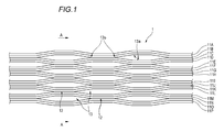
- FIG. 1 is a diagram showing an example of an intermittently connected optical fiber tape core wire according to the present embodiment.
- FIG. 2 is a cross-sectional view taken along the line AA of the intermittently connected optical fiber tape core wire shown in FIG.
- FIG. 3 is a cross-sectional view taken along the line AA of the intermittently connected optical fiber tape core wire shown in FIG. 1 in a state where the non-connected portion is not expanded.
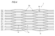
- FIG. 4 is a diagram showing another example of the intermittently connected optical fiber tape core wire according to the present embodiment.
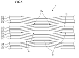
- FIG. 5 is a diagram showing still another example of the intermittently connected optical fiber tape core wire according to the present embodiment.
- FIG. 6 is a diagram for explaining the catenary amount of the intermittently connected optical fiber tape core wire.
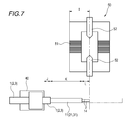
- FIG. 7 is a diagram showing an intermittently connected optical fiber tape core wire set in a fusion splicer holder and a fusion splicer.
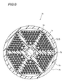
- FIG. 8 is a cross-sectional view showing an example of the optical fiber cable according to the present embodiment.
- FIG. 9 is a cross-sectional view showing another example of the optical fiber cable according to the present embodiment.
- FIG. 10 is a perspective view showing an example of an optical fiber cord with a connector according to the present embodiment.
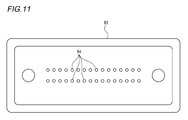
- FIG. 11 is a front view of a connector insertion / removal portion in the optical fiber cord with a connector shown in FIG.
- the conventional intermittently connected optical fiber tape core wire such as the optical fiber tape core wire described in Patent Documents 1 and 2 uses a thin optical fiber core wire as described above to form a divided portion or an intermittent pattern (connection).
- a portion (part, non-connected) portion is formed, the rigidity is lowered and the portion is easily bent. It is difficult to set such an intermittently connected optical fiber tape core wire at an accurate fusion position by using a fiber holder when collectively performing fusion splicing.
- the optical fiber core wire is bent and easily bent locally.
- the rigidity of the intermittently connected optical fiber tape core wire is too high, it becomes difficult to deform, so that the intermittently connected optical fiber tape core wire cannot absorb the bending pressure when bending pressure is applied. Therefore, when the optical fiber tape core wire is mounted at a high density on the optical fiber cable, macrobend loss, which is a bending loss due to an extremely small bending radius, is likely to occur.
- the present disclosure is an intermittent connection type in which even if a small-diameter optical fiber core wire is used, the optical fiber core wire is less likely to bend when collectively performing fusion splicing, and macrobend loss is less likely to occur even when the density is increased. It is an object of the present invention to provide an optical fiber tape core wire, an optical fiber cable, and an optical fiber cord with a connector.
- the intermittently connected optical fiber tape core wire is (1) In a state where a plurality of optical fiber core wires are arranged in parallel in a direction orthogonal to the longitudinal direction of the plurality of optical fiber core wires, in a part or all of the plurality of optical fiber core wires. Intermittent connection in which a connecting portion in which adjacent optical fiber cores are connected and a non-connecting portion in which adjacent optical fiber cores are not connected are intermittently provided in the longitudinal direction.
- Type optical fiber tape core wire The outer diameter of each of the plurality of optical fiber core wires is 160 ⁇ m or more and 220 ⁇ m or less.
- the amount of categorization at the tip of the intermittently connected optical fiber tape core wire is 0.1 mm or more and 2 mm or less.
- the intermittently connected optical fiber tape core wire of the present disclosure has a catenary amount of 0.1 mm or more and 2 mm or less at the gripped tip even if the optical fiber core wire has an outer diameter of 160 ⁇ m or more and 220 ⁇ m or less. ..
- the catenary amount is 2 mm or less, the rigidity is moderately large, and the optical fiber core wire set in the fiber holder is less likely to bend. Therefore, the position of the tip of the optical fiber core wire is unlikely to shift when the fusion splicing is performed collectively. Further, when the fused intermittently connected optical fiber tape core wire is conveyed to the protective sleeve heating portion, it is difficult to bend locally.
- the catenary amount is 0.1 mm or more, the intermittently connected optical fiber tape core wire is not too rigid, can be appropriately deformed with respect to the bending pressure, and can absorb the bending pressure. Therefore, when the intermittently connected optical fiber tape core wire is mounted on the optical fiber cable at a high density, macrobend loss, which is a bending loss due to an extremely small bending radius, is unlikely to occur.
- the intermittently connected optical fiber tape core wire is The number of the plurality of optical fiber cores may be 16, and the width in the arrangement direction may be 3.5 mm or less. According to this configuration, even if the number of optical fiber cores is 16, the width of the intermittently connected optical fiber tape cores in the arrangement direction is 3.5 mm or less, so that the existing 12-core batch fusion splicer Can be used for batch fusion splicing.
- the distance between the centers of the adjacent optical fiber core wires may be 200 ⁇ m ⁇ 30 ⁇ m. According to this configuration, since the distance between the centers of the adjacent optical fiber core wires is 200 ⁇ m ⁇ 30 ⁇ m, the width of the intermittently connected optical fiber tape core wires in the arrangement direction can be reduced.
- the number of the plurality of optical fiber core wires is It may be a multiple of 8 and may have 16 or more cores. According to this configuration, since the number of optical fiber cores is a multiple of 8, bidirectional transmission can be easily performed every four cores. Moreover, since the number of cores is 16 or more, it is easy to increase the rigidity of the intermittently connected optical fiber tape core wire.
- the plurality of optical fiber core wires include a glass fiber and a two-layer coating layer that covers the periphery of the glass fiber.
- the inner coating layer of the two coating layers is formed of the primary resin.
- the outer coating layer of the two coating layers is formed of a secondary resin.
- the secondary resin may have a Young's modulus of 900 MPa or more at 23 ° C. According to this configuration, since the Young's modulus of the secondary resin at 23 ° C. is 900 MPa or more, the coating layer on the outer side of the optical fiber core wire is appropriately hard. Therefore, microbend loss that occurs when a non-uniform lateral pressure is applied to the optical fiber core wire is unlikely to occur. Therefore, the lateral pressure characteristic of the intermittently connected optical fiber tape core wire is improved.
- the intermittently connected optical fiber tape core wire is The connecting portion and the non-connecting portion are formed for every four cores. Between the adjacent optical fiber core wires, the connecting portion where the tape resin covering the optical fiber core wires is continuous, and A non-connecting portion in which a slit is formed between the adjacent optical fiber core wires so as to penetrate the upper and lower surfaces of the intermittently connected optical fiber tape core wire with respect to the tape resin. Have, The end portion of the slit may be formed so as to cut at an acute angle with respect to the boundary with the connecting portion.
- the tape resin of the connecting portion between the optical fiber core wires in which the non-connecting portion is formed can be easily torn from the boundary formed so that the end portion of the slit is cut at an acute angle. .. Since the non-connecting portion is formed for each of the four cores, the intermittently connected optical fiber tape core wire can be easily divided into every four cores or every multiple core of 4.
- the optical fiber cable according to one aspect of the present disclosure is (8) An optical fiber cable to which the intermittently connected optical fiber tape core wire according to any one of (1) to (7) above is mounted.
- the core density is 4.5 cores / mm 2 or more.
- the optical fiber core wire can be mounted at a high density.
- the rigidity of the intermittently connected optical fiber tape core wire mounted on the optical fiber cable is considered to be moderately high. Therefore, the position of the tip of the optical fiber core wire is set when the intermittently connected optical fiber tape core wire taken out from the optical fiber cable in which the optical fiber core wire is mounted at high density is collectively fused and connected. Hard to slip.
- the intermittently connected optical fiber tape core wire taken out from the optical fiber cable and fused as described above is not easily bent locally when being conveyed to the protective sleeve heating portion. Further, the intermittently connected optical fiber tape core wire is not too rigid, can be appropriately deformed with respect to the bending pressure, and can absorb the bending pressure. Therefore, when the intermittently connected optical fiber tape core wire is mounted on the optical fiber cable at a high density, macrobend loss, which is a bending loss due to an extremely small bending radius, is unlikely to occur.
- the optical fiber cord with a connector is (9) The optical fiber cord including the intermittently connected optical fiber tape core wire according to any one of (1) to (7) above, and a connector connected to the optical fiber cord.
- the intermittently connected optical fiber tape core wire included in the optical fiber cord has moderately high rigidity, so that when the optical fiber cord with a connector is manufactured, it is separated into the optical fiber core wire and set in the connector.
- each optical fiber core wire is hard to bend. Therefore, since the optical fiber core wires in the connector can be easily set in a desired arrangement at a desired arrangement pitch, it is possible to provide an optical fiber cord with a connector that is easy to manufacture.
- the intermittently connected optical fiber tape core wire is not too rigid, can be appropriately deformed with respect to the bending pressure, and can absorb the bending pressure. Therefore, even if the density of the optical fiber cord is increased, macrobend loss, which is a bending loss due to the extremely small bending radius, is unlikely to occur.
- the optical fiber core wire is less likely to bend when collectively performing fusion splicing, and macrobend loss is less likely to occur even when the density is increased.
- Connected fiber optic tape cores, fiber optic cables and fiber optic cords with connectors can be provided.
- the optical fiber tape core wire 1 of this example is a plurality of optical fiber core wires 11 (11A to 11P in this example) (the number of optical fiber core wires is 16 in this example). Are arranged in parallel in a direction orthogonal to the longitudinal direction of the optical fiber core wire 11.
- the 16-core optical fiber core wires 11A to 11P are connected by resin with at least a part of the adjacent optical fiber core wires in contact with each other.
- the optical fiber tape core wire 1 is a connecting portion in a state in which the optical fiber core wires are connected to each other with a resin for each of the two optical fiber core wires in a part or all of the plurality of optical fiber core wires 11.
- This is an intermittently connected optical fiber tape core wire in which 12 and a non-connecting portion 13 in which the optical fiber core wires are not connected to each other by a resin are intermittently provided in the longitudinal direction.
- the optical fiber tape core wire 1 In the optical fiber tape core wire 1, the core wire between the optical fiber core wire 11B and 11C, the core wire between the optical fiber core wire 11D and 11E, the core wire between the optical fiber core wire 11F and 11G, and the optical fiber core wire Between the cores of the wires 11H and 11I, between the cores of the optical fiber cores 11J and 11K, between the cores of the optical fiber cores 11L and 11M, and between the cores of the optical fiber cores 11N and 11O. , A connecting portion 12 and a non-connecting portion 13 are provided.
- FIG. 1 shows an optical fiber tape core wire 1 in a state in which the non-connecting portion 13 is expanded in the arrangement direction of the optical fiber core wires 11A to 11P.
- FIG. 2 shows a cross-sectional view taken along the line AA of the optical fiber tape core wire 1 of FIG.
- FIG. 3 shows a cross-sectional view taken along the line AA of the optical fiber tape core wire 1 in a state where the non-connecting portion 13 is not expanded.
- an intermittently connected optical fiber tape core wire composed of 16 optical fiber core wires is shown, but the number of optical fiber core wires is not limited to 16.
- the number of optical fiber cores may be 16 or more and a multiple of 8.
- the number of optical fiber cores may be, for example, 24 cores, 32 cores, ..., 96 cores, or the like.
- the optical fiber core wire 11 has, for example, a glass fiber 14 composed of a core and a clad, and a two-layer coating layer that covers the periphery of the glass fiber 14.
- the inner coating layer of the two coating layers is formed of the primary resin 15.
- the outer coating layer of the two coating layers is formed of the secondary resin 16.
- the primary resin 15 in contact with the glass fiber 14 a soft resin having a relatively low Young's modulus is used as the buffer layer.
- a hard resin having a relatively high Young's modulus is used as the protective layer.
- the secondary resin 16 has, for example, a Young's modulus at 23 ° C. of 900 MPa or more, preferably 1000 MPa or more, and more preferably 1500 MPa or more.
- the primary resin 15 and the secondary resin 16 are formed of, for example, an ultraviolet curable resin, a thermosetting resin, or the like.
- a tape resin 17 for connecting the optical fiber core wires 11A to 11P is provided around the optical fiber core wire 11.
- the optical fiber core wires 11A to 11P are arranged in parallel in a contacted state, and are collectively covered with a tape resin 17 and connected.
- the tape resin 17 to be collectively coated is provided so as to have a recess 17a between the cores of the optical fiber cores according to the recess formed between the cores of the adjacent optical fiber cores.
- a connecting portion 12 and a non-connecting portion 13 are intermittently provided in the longitudinal direction for each of the two optical fiber core wires as described above. In this way, the cores of each of the two optical fiber cores in the optical fiber tape core 1 are intermittently connected by the tape resin 17 in the longitudinal direction of the optical fiber tape core 1.
- the non-connecting portion 13 of the optical fiber tape core wire 1 has a connecting portion at the end of the slit 13a penetrating the upper and lower surfaces of the optical fiber tape core wire 1 with respect to the tape resin 17. It is formed so as to cut sharply with respect to the boundary 13b with 12.
- Such a slit 13a is formed by cutting the tape resin 17 of the recess 17a provided between the core wires of the optical fiber core wire.
- the outer diameter B (see FIG. 3) of each of the optical fiber core wires 11A to 11P is 160 ⁇ m or more and 220 ⁇ m or less.
- the distance C between the centers of adjacent optical fiber core wires in the optical fiber core wires 11A to 11P is 170 ⁇ m or more and 230 ⁇ m or less.
- the thickness D of the optical fiber tape core wire 1 is 255 ⁇ m or less.
- the width E of the optical fiber tape core wire 1 (width in the direction in which the optical fiber core wires are arranged) E is 3.5 mm or less when the number of optical fiber core wires is 16.
- the optical fiber tape core wire 1 of this example has a configuration in which the optical fiber core wires 11A to 11P are arranged in parallel in contact with each other and the periphery thereof is covered with the tape resin 17, but the configuration is not limited to this.
- the optical fiber core wires 11A to 11P are arranged in parallel in a state where there is a slight gap between the adjacent optical fiber core wires, and the optical fiber core wire is in a state where the tape resin 17 is inserted in the gap between the core wires. It may be configured to cover 11A to 11P.
- FIG. 4 is a diagram showing another example of the optical fiber tape core wire according to the present embodiment.
- the optical fiber tape core wire 2 of this example every two optical fiber core wires are provided in that a connecting portion 22 and a non-connecting portion 23 are provided between the optical fiber core wires. It is different from the optical fiber tape core wire 1 of FIG. 1 in which the connecting portion 12 and the non-connecting portion 13 are provided.
- the non-connecting portion 23 is formed so that the end portion of the slit 23a is cut at an acute angle with respect to the boundary 23b with the connecting portion 22, similarly to the non-connecting portion 13 in the optical fiber tape core wire 1 of FIG.
- the optical fiber tape core wire 2 has 16 core optical fiber core wires 21 (21A to 21P in this example), and the number of optical fiber core wires is the same as that of the optical fiber tape core wire 1 of FIG. is there.
- Other configurations for example, the glass fiber and coating layer constituting the optical fiber core wire, the outer diameter B of the optical fiber core wire and the distance C between the centers, the bending loss of the optical fiber core wire, and the thickness D of the optical fiber tape core wire.
- the width E and the like are the same as those of the optical fiber tape core wire 1 of FIG.
- FIG. 5 is a diagram showing still another example of the optical fiber tape core wire according to the present embodiment.
- the optical fiber tape core wire 3 of this example has two optical fiber cores in that a connecting portion 32 and a non-connecting portion 33 are provided for each of the four optical fiber core wires. This is different from the optical fiber tape core wire 1 of FIG. 1, in which a connecting portion 12 and a non-connecting portion 13 are provided for each wire.
- the non-connecting portion 33 is formed so that the end portion of the slit 33a is cut at an acute angle with respect to the boundary 33b with the connecting portion 32, similarly to the non-connecting portion 13 in the optical fiber tape core wire 1 of FIG.
- the optical fiber tape core wire 3 has 16 core optical fiber core wires 31 (31A to 31P in this example), and the number of optical fiber core wires is the same as that of the optical fiber tape core wire 1 of FIG. is there.
- Other configurations are the same as those of the optical fiber tape core wire 2 shown in FIG. 4 and the same as the optical fiber tape core wire 1 of FIG.
- FIG. 6 is a diagram for explaining the catenary amount of the above-mentioned optical fiber tape core wires 1, 2, and 3.
- the misalignment error of the optical fiber core wire at the time of fusion and specify the appropriate rigidity of the optical fiber tape core wire.
- the tip F means a tip portion when the optical fiber tape core wire 1 (2, 3) is cut in a direction orthogonal to the longitudinal direction of the optical fiber tape core wire 1 (2, 3).
- the optical fiber is set so that the catalyst amount H of the tip F of the optical fiber tape core wire 1 (2, 3) is 2 mm or less. It defines the rigidity of the tape core wire 1 (2, 3).
- FIG. 7 shows the positional relationship between the fusion splicer 50 and the optical fiber tape core wire 1 (2, 3) set in the fiber holder 40 when the optical fiber tape core wire 1 (2, 3) is fused. It is a figure.
- the fusion splicer 50 has a V-groove 51 in which the optical fiber core wires 11 (21, 31) of the optical fiber tape core wires 1 (2, 3) are housed, and a pair for discharging.
- a discharge unit 52 having an electrode of the above is provided.
- Up to is the state of the optical fiber tape core wire 1 (2, 3) containing the tape resin 17.
- the portion having a length L 0.5 mm to 2 mm from the tip of the optical fiber core wire 11 (21, 31) is in the state of the glass fiber 14 from which the primary resin 15 and the secondary resin 16 have been peeled off.
- two optical fiber tape core wires set in the two fiber holders 40 are attached to the fusion splicer 50 so that the tips of the glass fibers 14 are abutted between the pair of electrodes of the discharge unit 52. Be placed.
- each V groove 51 of the fusion splicer 50 accommodates the optical fiber core wire 11 (21, 31) portion from which the tape resin 17 has been peeled off.
- an arc discharge is performed from the pair of electrodes of the discharge unit 52, and the two optical fiber tape core wires 1 (2, 3) are fused to each other.
- the catenary amount H at the tip F of the optical fiber tape core wire 1 (2, 3) is set to 0.1 mm or more. It defines the rigidity of the optical fiber tape core wire 1 (2, 3).
- each of the optical fiber core wires 11 (21, 31) of the optical fiber tape core wire 1 (2, 3) is 160 ⁇ m or more and 220 ⁇ m or less.
- the optical fiber tape core wire 1 (2, 3) has a catenary at the tip when the optical fiber tape core wire 1 (2, 3) is horizontally gripped from a position of 30 mm to a predetermined position with reference to the tip of the optical fiber tape core wire 1 (2, 3).
- the amount is configured to be 0.1 mm or more and 2 mm or less.
- the optical fiber tape core wire 1 (2, 3) Since the amount of the catenary of the optical fiber tape core wire 1 (2, 3) is 2 mm or less, the rigidity is moderately high, and the optical fiber tape core wire 1 (2, 3) is set in the fiber holder 40 at the time of fusion. However, the optical fiber core wire 11 (21, 31) is hard to bend. Therefore, the tips of the optical fiber tape core wires 1 (2, 3) do not spread in the width direction for each core wire when the fusion connection is performed collectively, and the axes of the optical fiber tape core wires to be fused are fused. It is possible to make it difficult for deviation to occur.
- the optical fiber tape core wire 1 (2, 3) is transported to, for example, the protective sleeve heating portion in the next manufacturing process, the optical fiber tape core wire 1 (2, 3) is locally bent. Can be made less likely to occur. Therefore, in this example, the connection work of the optical fiber tape core wire 1 (2, 3) can be efficiently performed.
- the catenary amount of the optical fiber tape core wire 1 (2, 3) is 0.1 mm or more, the rigidity is not too large. Therefore, the optical fiber tape core wire 1 (2, 3) can be appropriately deformed with respect to the bending pressure, and can absorb the bending pressure. Therefore, when the optical fiber tape core wires 1 (2, 3) are mounted at high density on the optical fiber cable, macrobend loss due to the extremely small bending radius is unlikely to occur.
- the secondary resin 16 forming the outer coating layer of the optical fiber core wire 11 (21, 31) has a Young's modulus of 900 MPa or more at 23 ° C., for example. Since the secondary resin 16 is moderately hard, microbend loss is unlikely to occur even when a non-uniform lateral pressure is applied to the optical fiber core wires 11 (21, 31). Therefore, in this example, the lateral pressure characteristic of the optical fiber tape core wire 1 (2, 3) can be improved.
- the optical fiber tape core wires 1 (2, 3) are configured such that the number of optical fiber core wires is 16 and the width in the arrangement direction thereof is 3.5 mm or less. This width is equivalent to the width of a conventional 12-core optical fiber tape core wire having an outer diameter of 250 ⁇ m. As a result, in this example, the optical fiber tape core wires 1 (2, 3) are collectively fused and connected using the existing 12-core batch fusion splicer even if the number of optical fiber cores is 16. Can be done.
- the optical fiber tape core wire 1 (2, 3) is configured such that the distance C between the centers of the adjacent optical fiber core wires 11 (21, 31) is 200 ⁇ m ⁇ 30 ⁇ m, this example is an optical fiber.
- the width of the optical fiber core wire 11 (21, 31) in the tape core wire 1 (2, 3) in the arrangement direction can be reduced.
- the conventional 12-core optical fiber tape core wire when performing bidirectional transmission for each of the 4 cores, 8 of the 12 cores may be used and the remaining 4 cores may not be used.
- the optical fiber tape core wires 1 (2, 3) are multiple cores of 8, all the optical fiber core wires 11 (21, 31) are used in both directions every four cores. Easy to transmit. Further, even if the multi-core optical fiber tape core wire 1 (2, 3) is composed of 16 cores or more, the rigidity is not too large, and the optical fiber tape core wire 1 (2, 3) is appropriate for bending pressure. Can be transformed into.
- the bending loss of the fiber tape core wire 1 (2, 3) can be sufficiently reduced.
- the non-connecting portion 13 (23, 33) connects the optical fiber tape core wire 1 (2, 3) with respect to the tape resin 17 between the adjacent optical fiber core wires.
- the ends of the slits 13a (23a, 33a) penetrating the upper and lower surfaces of the above) are formed so as to cut sharply with respect to the boundary 13b (23b, 33b) with the connecting portion 12 (22, 32).
- the non-connecting portion 13 (23, 33) is formed starting from the boundary 13b (23b, 33b) formed so that the end portion of the slit 13a (23a, 33a) is cut at an acute angle.
- the tape resin 17 of the connecting portion 12 (22, 32) between the optical fiber core wires can be easily torn. Since the optical fiber tape core wire 3 has non-connecting portions 13 (23, 33) formed for each of the four cores, the optical fiber tape core wire 3 can be easily divided into four cores or multiple cores of four. can do.
- FIG. 8 is a diagram showing an example of a slotless type optical fiber cable using the optical fiber tape core wire 1 (2, 3) of the present embodiment.
- FIG. 9 is a diagram showing an example of a slot-type optical fiber cable using the optical fiber tape core wire 1 (2, 3) according to the present embodiment.
- the slotless optical fiber cable 60 shown in FIG. 8 includes a cylindrical tube 61 and a plurality of optical fiber tape core wires 1 (2, 3) mounted in the tube 61.
- Each optical fiber tape core wire 1 (2, 3) is assembled so as to be rolled and twisted together.
- a plurality of interpositions tensile fibers, etc.
- a jacket 64 is covered around the tube 61 together with the tension member 63.
- a tear string 65 is provided inside the outer cover 64.
- the core density of the optical fiber core wires 11 (21, 31) per unit area in the cable cross section is 4.5 cores / mm 2 or more.
- the core density is calculated by the number of optical fiber core wires / the cross section of the optical fiber cable.
- the slotless optical fiber cable 60 shown in FIG. 8 has 432 cores, and when the optical fiber cable 60 is manufactured with an outer diameter of 11 mm, the optical fiber core wires 11 (21, 31) are contained in the optical fiber cable 60. Can be mounted with a core density of 4.55 cores / mm 2 .
- the slot-type optical fiber cable 70 shown in FIG. 9 includes a slot rod 72 having a plurality of slot grooves 71, and a plurality of optical fiber tape core wires 1 (2, 3) housed in the slot grooves 71. ing.
- the slot rod 72 has a tension member 73 in the center of the optical fiber cable 70, and has a structure in which a plurality of slot grooves 71 are provided radially.
- Each optical fiber tape core wire 1 (2, 3) is assembled so as to be rolled, twisted with each other, and housed in the slot groove 71.
- a presser foot tape 74 is wound around the slot rod 72, and an outer cover 75 is formed around the presser foot tape 74.
- the core density is 4.55 cores / mm 2 or more.
- the slot-type optical fiber cable 70 shown in FIG. 9 has 3120 cores, and when the optical fiber cable 70 is manufactured with an outer diameter of 28 mm, the optical fiber core wires 11 (21, 31) are provided in the optical fiber cable 70. It can be accommodated at a core density of 5.07 cores / mm 2 .
- the optical fiber cables 60 and 70 are configured so that the core density of the optical fiber cable is 4.5 cores / mm 2 or more. Therefore, in this example, the optical fiber core wires 11 (21, 31) can be mounted at high density on the optical fiber cables 60 and 70.
- the rigidity of the optical fiber tape core wires 1 (2, 3) mounted on the optical fiber cables 60 and 70 is configured to be appropriately increased. Therefore, when the optical fiber tape core wires 1 (2, 3) are taken out from the optical fiber cables 60, 70 on which the optical fiber core wires 11 (21, 31) are mounted at high density and fusion-bonded together.
- the optical fiber core wire 11 (21, 31) is hard to bend and the position of the tip is hard to shift.
- the optical fiber tape core wires 1 (2, 3) taken out from the optical fiber cables 60 and 70 and fused as described above are locally transferred to the protective sleeve heating unit in the next manufacturing process, for example. It is hard to bend. Further, since the rigidity of the optical fiber tape core wire 1 (2, 3) is not too large, the optical fiber tape core wire 1 (2, 3) can be appropriately deformed with respect to the bending pressure and absorbs the bending pressure. it can. Therefore, when the optical fiber tape core wires 1 (2, 3) are mounted at high density on the optical fiber cables 60 and 70, macro bend loss, which is a bending loss due to an extremely small bending radius, is unlikely to occur. ..
- FIG. 10 is a diagram showing an example of an optical fiber cord with a connector using the optical fiber tape core wire 1 (2, 3) of the present embodiment.
- FIG. 11 is a front view of a connector insertion / removal portion in the optical fiber cord with a connector shown in FIG.
- the optical fiber cord 80 with a connector includes an optical fiber cord 81 containing an optical fiber tape core wire 1 (2, 3) and a connector portion 82 connected to the optical fiber cord 81. , Is equipped.
- the connector unit 82 is composed of an MPO (Multi-fiber Push-on) connector capable of collectively connecting a plurality of optical fiber core wires. As shown in FIG.
- the connector portion 82 includes an insertion / extraction portion 83 for inserting / removing into another connector, an adapter, or the like, and the insertion / extraction portion 83 is formed with each optical fiber of the optical fiber tape core wire 1 (2, 3).
- 32 through holes 84 (16 ⁇ 2 rows) through which the tip ends of the core wires 11 (21, 31) are inserted are provided.
- the optical fiber tape core wire 1 (2, 3) included in the optical fiber cord 80 with a connector has moderately high rigidity. Therefore, when the optical fiber cord 80 with a connector is manufactured, the optical fiber core wires 11 (21, 31) are separated and set in the connector portion 82, and the respective optical fiber core wires are less likely to bend. Therefore, the optical fiber cord 80 with a connector connects the optical fiber core wires 11 (21, 31) of the multi-core optical fiber tape core wires 1 (2, 3) housed in the connector portion 82 with 16 or more cores. , It can be easily set (wired) in a desired arrangement at a desired arrangement pitch. Therefore, the optical fiber cord 80 with a connector is easy to manufacture.
- the rigidity of the optical fiber tape core wire 1 (2, 3) is not too large, the optical fiber tape core wire 1 (2, 3) can be appropriately deformed with respect to the bending pressure and can absorb the bending pressure. Therefore, when the optical fiber tape core wires 1 (2, 3) are mounted on the optical fiber cord 81 at a high density, macro bend loss, which is a bending loss due to an extremely small bending radius, is unlikely to occur.
- connection workability and high density were evaluated for a plurality of samples having different catenary amounts H.
- the evaluation results are shown in Table 1 together with the evaluation of the non-intermittent optical fiber tape core wire as a comparative example.
- sample No. All of 1 to 9 are 16-core optical fiber tape core wires, and a resin having a Young's modulus of 900 MPa at 23 ° C. was used as the secondary resin 16 of the optical fiber core wires in each optical fiber tape core wire.
- the outer diameter of each optical fiber core wire is 200 ⁇ m.
- Sample No. Reference numerals 1 to 8 are intermittently connected optical fiber tape core wires, and sample Nos. Reference numeral 9 denotes a non-intermittent optical fiber tape core wire as a comparative example.
- Sample No. In Nos. 1 to 4 the intermittent pattern is for each core, and the intermittent pattern is the same as that of the optical fiber tape core wire 2.
- Sample No. In 5 to 8 the intermittent pattern is every two cores, and the intermittent pattern is the same as that of the optical fiber tape core wire 1.
- the connecting portion ratio represents the ratio of the length of the connecting portion to the length of the non-connecting portion in the longitudinal direction of the intermittently connected optical fiber tape core wire.
- the ratio of the connecting portions is increased, the area occupied by the connecting portion in the intermittently connected optical fiber tape core wire becomes large, and the rigidity of the intermittently connected optical fiber tape core wire increases. Therefore, the intermittently connected optical fiber tape core wire is less likely to bend and the catenary amount H becomes smaller.
- the ratio of the connecting portions is reduced, the area occupied by the connecting portion in the intermittently connected optical fiber tape core wire becomes small, and the rigidity of the intermittently connected optical fiber tape core wire becomes low. Therefore, the intermittently connected optical fiber tape core wire tends to bend and the catenary amount H becomes large.
- the catenary amount H changes by changing the connecting portion ratio.
- connection workability when the optical fiber tape core wire was fused using the fiber holder 40 and the fusion splicer 50 shown in FIG. 7, the sample No. which was a non-intermittent optical fiber tape core wire. It is a relative value with the working time according to 9 as 1.0. Then, those having a connection workability exceeding 1.5 were judged to have poor workability and were evaluated as B. Further, the one having a connection workability of 1.5 or less is judged to have good workability and is evaluated as A, and the one having 1.0 (equivalent to non-intermittent) is judged to have better workability and is evaluated as S. did. That is, the sample of evaluation A or evaluation S is an intermittently connected optical fiber tape core wire having good connection workability.
- the high density is the maximum that can be mounted so that the wavelength of the signal light is 1.55 ⁇ m and the bending loss is 0.3 dB / km or less when the optical fiber tape core wire of the above sample is mounted on the optical fiber cable 60. It was evaluated by the heart density of.
- the evaluation standard is the sample No. which is a non-intermittent optical fiber tape core wire. If it is larger than the core density of 9 (4.0 cores / mm 2 ), it is judged that the high density is good, and the core density is 4.5 cores / mm 2 or more and 5.0 cores / mm 2 or less. Was evaluated as A, and those having a core density exceeding 5.0 cores / mm 2 were evaluated as S. Further, those having a core density of 4.0 cores / mm 2 or less were judged to be inferior in high density and evaluated as B. That is, the sample of evaluation A or evaluation S is an intermittently connected optical fiber tape core wire having good high density.
Landscapes
- Physics & Mathematics (AREA)
- General Physics & Mathematics (AREA)
- Optics & Photonics (AREA)
- Engineering & Computer Science (AREA)
- Manufacturing & Machinery (AREA)
- Mechanical Coupling Of Light Guides (AREA)
Abstract
Description
本出願は、2019年3月20日出願の日本出願第2019-052762号に基づく優先権を主張し、前記日本出願に記載された全ての記載内容を援用するものである。
特許文献2には、3心以上の光ファイバが並列して配置される光ファイバテープ心線が記載されている。互いに隣接する2心の光ファイバ間を連結部で連結し、該連結部を、テープ心線長手方向及びテープ心線幅方向にそれぞれ間欠的に設けた光ファイバテープ心線が記載されている。さらに、特許文献2には、光ファイバテープ心線を構成する光ファイバの外径寸法を220μm以下とし、且つ隣り合う光ファイバの中心間距離を250±30μmとしたことが記載されている。
複数の光ファイバ心線が、前記複数の光ファイバ心線の長手方向と直交する方向に並列に配置された状態で、前記複数の光ファイバ心線間の一部、または全てにおいて、隣接する光ファイバ心線間が連結された状態の連結部と、隣接する光ファイバ心線間が連結されていない状態の非連結部とが前記長手方向に間欠的に設けられている、間欠連結型光ファイバテープ心線であって、
前記複数の光ファイバ心線のそれぞれの外径が、160μm以上220μm以下であり、
当該間欠連結型光ファイバテープ心線が、前記間欠連結型光ファイバテープ心線の先端を基準に30mmの位置から所定の位置まで水平方向に把持された際に、把持された箇所から突出した前記間欠連結型光ファイバテープ心線の前記先端のカテナリー量が0.1mm以上2mm以下である。
上記間欠連結型光ファイバテープ心線が実装された光ファイバケーブルであって、
心密度が4.5心/mm2以上である。
上記間欠連結型光ファイバテープ心線を含む光ファイバコードと、前記光ファイバコードに接続されたコネクタと、を有する。
光ファイバケーブルにおいて光ファイバの高密度化を検討するに際し、従来の径250μmよりも細い光ファイバ心線を用いた間欠連結型の光ファイバテープ心線を実装することが考えられる。
ところが、特許文献1、2に記載された光ファイバテープ心線などの従来の間欠連結型の光ファイバテープ心線は、上記のような細い光ファイバ心線を用いて分断部や間欠パターン(連結部、非連結)部を形成すると、剛性が低くなり、撓み易い。そのような間欠連結型光ファイバテープ心線は、一括して融着接続を行う際にファイバホルダを用いて正確な融着位置にセットすることが難しい。また、融着した間欠連結型光ファイバテープ心線を保護スリーブ加熱部に搬送する際に、光ファイバ心線が撓んで局所的に曲がりやすい。一方、間欠連結型光ファイバテープ心線の剛性が高すぎる場合は、変形し難くなるので、曲げ圧力が加わった場合に間欠連結型光ファイバテープ心線は曲げ圧力を吸収できない。このため、光ファイバケーブルに光ファイバテープ心線を高密度に実装すると、曲げ半径が極端に小さいことに起因する曲げ損失であるマクロベンドロスが生じやすい。
最初に本開示の実施態様を列記して説明する。
本開示の一態様に係る間欠連結型光ファイバテープ心線は、
(1)複数の光ファイバ心線が、前記複数の光ファイバ心線の長手方向と直交する方向に並列に配置された状態で、前記複数の光ファイバ心線間の一部、または全部において、隣接する光ファイバ心線間が連結された状態の連結部と、隣接する光ファイバ心線間が連結されていない状態の非連結部とが前記長手方向に間欠的に設けられている、間欠連結型光ファイバテープ心線であって、
前記複数の光ファイバ心線のそれぞれの外径が、160μm以上220μm以下であり、
当該間欠連結型光ファイバテープ心線が、前記間欠連結型光ファイバテープ心線の先端を基準に30mmの位置から所定の位置まで水平方向に把持された際に、把持された箇所から突出した前記間欠連結型光ファイバテープ心線の前記先端のカテナリー量が0.1mm以上2mm以下である。
本開示の間欠連結型光ファイバテープ心線は、外径が160μm以上220μm以下である細径の光ファイバ心線であっても、把持された先端のカテナリー量が0.1mm以上2mm以下である。すなわち、上記カテナリー量が2mm以下であるので剛性が適度に大きく、ファイバホルダにセットした光ファイバ心線が撓みにくい。したがって、一括して融着接続を行う際に光ファイバ心線の先端の位置がずれにくい。また、融着した間欠連結型光ファイバテープ心線を保護スリーブ加熱部に搬送する際に、局所的に曲がりにくい。一方、上記カテナリー量が0.1mm以上であるので、間欠連結型光ファイバテープ心線は剛性が大き過ぎず、曲げ圧力に対して適度に変形することができ、曲げ圧力を吸収できる。したがって、光ファイバケーブルに間欠連結型光ファイバテープ心線を高密度に実装した際に、曲げ半径が極端に小さくなることに起因する曲げ損失であるマクロベンドロスが生じにくい。
前記複数の光ファイバ心線の数が16心であり、かつ、配列方向の幅が3.5mm以下であってもよい。
本構成によれば、光ファイバ心線数が16心であっても、間欠連結型光ファイバテープ心線の配列方向の幅が3.5mm以下であるので、既存の12心一括融着接続機を用いて一括融着接続することができる。
本構成によれば、隣接する光ファイバ心線の中心間の距離が200μm±30μmであるので、間欠連結型光ファイバテープ心線の配列方向の幅を小さくすることができる。
8の倍数であり、かつ、16心以上であってもよい。
本構成によれば、光ファイバ心線数が、8の倍数であるので、4心毎に双方向伝送を行いやすい。かつ、16心以上であるので、間欠連結型光ファイバテープ心線の剛性を大きくし易い。
曲げ半径R=15mmのとき、曲げ損失が0.25dB/10ターン以下であってもよい。
本構成によれば、光ファイバ心線の曲げ半径R=15mmのとき、曲げ損失が0.25dB/10ターン以下であるので、曲げ損失を小さくできる。
前記二層の被覆層のうちの内側の被覆層は、プライマリ樹脂で形成され、
前記二層の被覆層のうちの外側の被覆層は、セカンダリ樹脂で形成されており、
前記セカンダリ樹脂は、23℃におけるヤング率が900MPa以上であってもよい。
本構成によれば、セカンダリ樹脂の23℃におけるヤング率が900MPa以上であるので、光ファイバ心線の外側の被覆層が適度に硬い。このため、光ファイバ心線に不均一な側圧がかかった場合に生じるマイクロベンドロスが生じにくい。したがって、間欠連結型光ファイバテープ心線の側圧特性が良くなる。
4心毎に前記連結部と前記非連結部とが形成されており、
前記隣接する光ファイバ心線間で、前記光ファイバ心線を覆うテープ樹脂が連続する前記連結部と、
前記隣接する光ファイバ心線間で、前記テープ樹脂に対して当該間欠連結型光ファイバテープ心線の上下面を貫通するスリットが形成されている前記非連結部と、
を有し、
前記スリットの端部が、前記連結部との境界に対して鋭角に切れ込むように形成されていてもよい。
本構成によれば、スリットの端部が鋭角に切れ込むように形成された境界を起点として、非連結部が形成されている光ファイバ心線間の連結部のテープ樹脂を容易に引き裂くことができる。そして、4心毎に非連結部が形成されているので、間欠連結型光ファイバテープ心線を4心毎あるいは4の倍数心毎に容易に分割することができる。
(8)上記(1)から(7)のいずれか一つに記載の間欠連結型光ファイバテープ心線が実装された光ファイバケーブルであって、
心密度が4.5心/mm2以上である。
本構成によれば、光ファイバケーブルの心密度が4.5心/mm2以上であるので、光ファイバ心線を高密度に実装できる。そして、この光ファイバケーブルに実装された間欠連結型光ファイバテープ心線の剛性が適度に大きいものとされている。したがって、光ファイバ心線が高密度に実装された光ファイバケーブルから取り出した間欠連結型光ファイバテープ心線に対して、一括して融着接続を行う際に光ファイバ心線の先端の位置がずれにくい。また、上記のようにして光ファイバケーブルから取り出して融着された間欠連結型光ファイバテープ心線は、保護スリーブ加熱部に搬送する際に、局所的に曲がりにくい。
また、間欠連結型光ファイバテープ心線は剛性が大き過ぎず、曲げ圧力に対して適度に変形することができ、曲げ圧力を吸収できる。したがって、光ファイバケーブルに間欠連結型光ファイバテープ心線を高密度に実装した際に、曲げ半径が極端に小さくなることに起因する曲げ損失であるマクロベンドロスが生じにくい。
(9)上記(1)から(7)のいずれか一つに記載の間欠連結型光ファイバテープ心線を含む光ファイバコードと、前記光ファイバコードに接続されたコネクタと、を有する。
本構成によれば、光ファイバコードに含まれる間欠連結型光ファイバテープ心線は、剛性が適度に大きいので、コネクタ付き光ファイバコードの製造時に光ファイバ心線にばらしてコネクタ内にセットする際に、それぞれの光ファイバ心線が撓みにくい。このため、コネクタ内の光ファイバ心線を、所望の配列ピッチで所望の配列にセットすることが容易にできるので、製造が容易なコネクタ付き光ファイバコードを提供できる。
また、間欠連結型光ファイバテープ心線は剛性が大き過ぎず、曲げ圧力に対して適度に変形することが可能であり、曲げ圧力を吸収できる。したがって、光ファイバコードを高密度化しても曲げ半径が極端に小さくなることに起因する曲げ損失であるマクロベンドロスが生じにくい。
本開示によれば、細径の光ファイバ心線を用いても、一括して融着接続を行う際に光ファイバ心線が撓み難く、且つ高密度化してもマクロベンドロスが生じにくい、間欠連結型光ファイバテープ心線、光ファイバケーブルおよびコネクタ付き光ファイバコードを提供することができる。
本開示の実施形態に係る間欠連結型光ファイバテープ心線、光ファイバケーブルおよびコネクタ付き光ファイバコードの具体例を、以下に図面を参照しつつ説明する。
なお、本開示はこれらの例示に限定されるものではなく、請求の範囲によって示され、請求の範囲と均等の意味および範囲内でのすべての変更が含まれることが意図される。
プライマリ樹脂15およびセカンダリ樹脂16は、例えば紫外線硬化型樹脂、熱硬化型樹脂等で形成されている。光ファイバ心線11は、曲げ半径R=15mmのとき、曲げ損失が0.25dB/10ターン以下である。光ファイバ心線11は、側圧耐性を上げるため、ITU-T G.657.A/Bに規定されている曲げ強化型ファイバを用いてもよい。
これにより本例は、スリット13a(23a,33a)の端部が鋭角に切れ込むように形成された境界13b(23b,33b)を起点として、非連結部13(23,33)が形成されている光ファイバ心線間の連結部12(22,32)のテープ樹脂17を容易に引き裂くことができる。
そして、光ファイバテープ心線3は、4心毎に非連結部13(23,33)が形成されているので、光ファイバテープ心線3を4心毎あるいは4の倍数心毎に容易に分割することができる。
また、光ファイバテープ心線1(2,3)の剛性は大き過ぎないので、光ファイバテープ心線1(2,3)は曲げ圧力に対して適度に変形することができ、曲げ圧力を吸収できる。
したがって、光ファイバケーブル60,70に光ファイバテープ心線1(2,3)を高密度に実装した際に、曲げ半径が極端に小さくなることに起因する曲げ損失であるマクロベンドロスが生じにくい。
光ファイバテープ心線1(2,3)の剛性は大き過ぎないので、光ファイバテープ心線1(2,3)は曲げ圧力に対して適度に変形することができ、曲げ圧力を吸収できる。したがって、光ファイバコード81に光ファイバテープ心線1(2,3)を高密度に実装した際に、曲げ半径が極端に小さくなることに起因する曲げ損失であるマクロベンドロスが生じにくい。
本実施形態に係る間欠連結型の光ファイバテープ心線において、カテナリー量Hが異なる複数のサンプルに対して、接続作業性および高密度性の評価を行った。その評価結果を、比較例として非間欠の光ファイバテープ心線の評価と共に、表1に示す。

一方、連結部比率を小さくすると、間欠連結型光ファイバテープ心線において連結部が占める領域が小さくなり、間欠連結型光ファイバテープ心線は、剛性が低くなる。このため、間欠連結型光ファイバテープ心線は、撓み易くなりカテナリー量Hが大きくなる。
以上のように、間欠連結型光ファイバテープ心線は、連結部比率を変更することにより、カテナリー量Hが変化する。
また、サンプルNo.1~9と同じ16心の光ファイバテープ心線を用い、間欠パターンが4心毎の場合も、カテナリー量Hが、0.3mm以上2.0mm以下であれば、接続作業性および高密度性が共に良好であった。
11,21,31:光ファイバ心線
12,22,32:連結部
13,23,33:非連結部
13a,23a,33a:スリット
13b,23b,33b:境界
14:ガラスファイバ
15:プライマリ樹脂
16:セカンダリ樹脂
17:テープ樹脂
40:ファイバホルダ
50:融着接続機
51:V溝
52:放電部
60,70:光ファイバケーブル
61:チューブ
64:外被
71:スロット溝
72:スロットロッド
75:外被
80:コネクタ付き光ファイバコード
81:光ファイバコード
82:コネクタ部
83:挿抜部
84:貫通孔
Claims (9)
- 複数の光ファイバ心線が、前記複数の光ファイバ心線の長手方向と直交する方向に並列に配置された状態で、前記複数の光ファイバ心線間の一部、または全てにおいて、隣接する光ファイバ心線間が連結された状態の連結部と、隣接する光ファイバ心線間が連結されていない状態の非連結部とが前記長手方向に間欠的に設けられている、間欠連結型光ファイバテープ心線であって、
前記複数の光ファイバ心線のそれぞれの外径が、160μm以上220μm以下であり、
当該間欠連結型光ファイバテープ心線が、前記間欠連結型光ファイバテープ心線の先端を基準に30mmの位置から所定の位置まで水平方向に把持された際に、把持された箇所から突出した前記間欠連結型光ファイバテープ心線の前記先端のカテナリー量が0.1mm以上2mm以下である、
間欠連結型光ファイバテープ心線。 - 前記間欠連結型光ファイバテープ心線は、
前記複数の光ファイバ心線の数が16心であり、かつ、配列方向の幅が3.5mm以下である、
請求項1に記載の間欠連結型光ファイバテープ心線。 - 前記隣接する光ファイバ心線の中心間の距離が200μm±30μmである、
請求項1または請求項2に記載の間欠連結型光ファイバテープ心線。 - 前記複数の光ファイバ心線の数は、
8の倍数であり、かつ、16心以上である、
請求項1または請求項3に記載の間欠連結型光ファイバテープ心線。 - 前記複数の光ファイバ心線は、
曲げ半径R=15mmのとき、曲げ損失が0.25dB/10ターン以下である、
請求項1から請求項4のいずれか一項に記載の間欠連結型光ファイバテープ心線。 - 前記複数の光ファイバ心線は、ガラスファイバと、前記ガラスファイバの周囲を覆う二層の被覆層と、を有し、
前記二層の被覆層のうちの内側の被覆層は、プライマリ樹脂で形成され、
前記二層の被覆層のうちの外側の被覆層は、セカンダリ樹脂で形成されており、
前記セカンダリ樹脂は、23℃におけるヤング率が900MPa以上である、
請求項1から請求項5のいずれか一項に記載の間欠連結型光ファイバテープ心線。 - 前記間欠連結型光ファイバテープ心線は、
4心毎に前記連結部と前記非連結部とが形成されており、
前記隣接する光ファイバ心線間で、前記光ファイバ心線を覆うテープ樹脂が連続する前記連結部と、
前記隣接する光ファイバ心線間で、前記テープ樹脂に対して当該間欠連結型光ファイバテープ心線の上下面を貫通するスリットが形成されている前記非連結部と、
を有し、
前記スリットの端部が、前記連結部との境界に対して鋭角に切れ込むように形成されている、
請求項1から請求項6のいずれか一項に記載の間欠連結型光ファイバテープ心線。 - 請求項1から請求項7のいずれか一項に記載の間欠連結型光ファイバテープ心線が実装された光ファイバケーブルであって、
心密度が4.5心/mm2以上である、
光ファイバケーブル。 - 請求項1から請求項7のいずれか一項に記載の間欠連結型光ファイバテープ心線を含む光ファイバコードと、前記光ファイバコードに接続されたコネクタと、を有する、
コネクタ付き光ファイバコード。
Priority Applications (3)
| Application Number | Priority Date | Filing Date | Title |
|---|---|---|---|
| JP2021507426A JPWO2020189772A1 (ja) | 2019-03-20 | 2020-03-19 | |
| US17/440,594 US12117662B2 (en) | 2019-03-20 | 2020-03-19 | Intermittent connection-type optical fiber tape core, optical fiber cable and connector-equipped optical fiber cord |
| EP20773448.4A EP3943992B1 (en) | 2019-03-20 | 2020-03-19 | Intermittent connection-type optical fiber tape core, optical fiber cable and connector-equipped optical fiber cord |
Applications Claiming Priority (2)
| Application Number | Priority Date | Filing Date | Title |
|---|---|---|---|
| JP2019-052762 | 2019-03-20 | ||
| JP2019052762 | 2019-03-20 |
Publications (1)
| Publication Number | Publication Date |
|---|---|
| WO2020189772A1 true WO2020189772A1 (ja) | 2020-09-24 |
Family
ID=72520298
Family Applications (1)
| Application Number | Title | Priority Date | Filing Date |
|---|---|---|---|
| PCT/JP2020/012419 Ceased WO2020189772A1 (ja) | 2019-03-20 | 2020-03-19 | 間欠連結型光ファイバテープ心線、光ファイバケーブルおよびコネクタ付き光ファイバコード |
Country Status (4)
| Country | Link |
|---|---|
| US (1) | US12117662B2 (ja) |
| EP (1) | EP3943992B1 (ja) |
| JP (1) | JPWO2020189772A1 (ja) |
| WO (1) | WO2020189772A1 (ja) |
Cited By (1)
| Publication number | Priority date | Publication date | Assignee | Title |
|---|---|---|---|---|
| WO2023120727A1 (ja) * | 2021-12-24 | 2023-06-29 | 住友電気工業株式会社 | 光ケーブル及び光ケーブルの製造方法 |
Families Citing this family (2)
| Publication number | Priority date | Publication date | Assignee | Title |
|---|---|---|---|---|
| JP2022183873A (ja) * | 2021-05-31 | 2022-12-13 | 住友電気工業株式会社 | 光ファイバリボン |
| US20230221514A1 (en) * | 2022-01-12 | 2023-07-13 | Sterlite Technologies Limited | Optical fiber cable with different binder pitch |
Citations (6)
| Publication number | Priority date | Publication date | Assignee | Title |
|---|---|---|---|---|
| JP2005062427A (ja) | 2003-08-11 | 2005-03-10 | Sumitomo Electric Ind Ltd | 光ファイバケーブル、光ファイバケーブルの製造方法及び光ファイバケーブルの製造装置 |
| JP2013088617A (ja) | 2011-10-18 | 2013-05-13 | Fujikura Ltd | 光ファイバテープ心線及びその光ファイバテープ心線を収納した光ファイバケーブル |
| JP2015007714A (ja) * | 2013-06-25 | 2015-01-15 | 住友電気工業株式会社 | 光ファイバテープ心線、光ケーブル、製造装置、及び製造方法 |
| WO2017145955A1 (ja) * | 2016-02-23 | 2017-08-31 | 住友電気工業株式会社 | 間欠連結型光ファイバテープ心線、間欠連結型光ファイバテープ心線の製造方法、光ファイバケーブルおよび光ファイバコード |
| WO2018182670A1 (en) * | 2017-03-31 | 2018-10-04 | Afl Telecommunications Llc | Single jacket reduced diameter ruggedized fiber optic distribution cables |
| JP2019052762A (ja) | 2012-09-28 | 2019-04-04 | ユナイテッド テクノロジーズ コーポレイションUnited Technologies Corporation | 歯車減速機 |
Family Cites Families (13)
| Publication number | Priority date | Publication date | Assignee | Title |
|---|---|---|---|---|
| US6584257B1 (en) * | 2000-12-27 | 2003-06-24 | Corning Cable Systems, Llc | Fiber optic assembly and method of making same |
| KR100960185B1 (ko) * | 2002-05-28 | 2010-05-27 | 스미토모 덴키 고교 가부시키가이샤 | 광파이버 테이프 코어 |
| JP2005114750A (ja) * | 2003-10-02 | 2005-04-28 | Fujikura Ltd | 分割型テープ心線および前記分割型テープ心線を用いた光ファイバテープコード、光ファイバケーブル並びに前記分割型テープ心線の分割方法 |
| JP4249202B2 (ja) * | 2006-03-31 | 2009-04-02 | 昭和電線ケーブルシステム株式会社 | 光ファイバテープおよび光ケーブル |
| WO2010001663A1 (ja) * | 2008-06-30 | 2010-01-07 | 日本電信電話株式会社 | 光ファイバケーブル及び光ファイバテープ |
| JP5944762B2 (ja) * | 2012-07-03 | 2016-07-05 | 昭和電線ケーブルシステム株式会社 | 間欠型光ファイバテープ心線の製造方法および製造装置 |
| JP2014211512A (ja) * | 2013-04-18 | 2014-11-13 | 住友電気工業株式会社 | 光ファイバコード |
| JP5852045B2 (ja) * | 2013-05-07 | 2016-02-03 | 株式会社フジクラ | 光ファイバテープ心線及び光ファイバケーブル |
| JP6569429B2 (ja) * | 2015-09-25 | 2019-09-04 | 住友電気工業株式会社 | 光ファイバテープ心線 |
| CN107001129B (zh) | 2015-11-09 | 2021-05-25 | 住友电气工业株式会社 | 光纤芯线 |
| JP6490805B2 (ja) * | 2015-12-01 | 2019-03-27 | 古河電気工業株式会社 | 光ファイバテープ心線及び光ファイバケーブル |
| US10989888B2 (en) * | 2016-02-02 | 2021-04-27 | Ofs Fitel, Llc | Flexible ribbon structure and method for making |
| JP6586925B2 (ja) * | 2016-06-13 | 2019-10-09 | 住友電気工業株式会社 | 光ファイバケーブル |
-
2020
- 2020-03-19 WO PCT/JP2020/012419 patent/WO2020189772A1/ja not_active Ceased
- 2020-03-19 US US17/440,594 patent/US12117662B2/en active Active
- 2020-03-19 EP EP20773448.4A patent/EP3943992B1/en active Active
- 2020-03-19 JP JP2021507426A patent/JPWO2020189772A1/ja active Pending
Patent Citations (6)
| Publication number | Priority date | Publication date | Assignee | Title |
|---|---|---|---|---|
| JP2005062427A (ja) | 2003-08-11 | 2005-03-10 | Sumitomo Electric Ind Ltd | 光ファイバケーブル、光ファイバケーブルの製造方法及び光ファイバケーブルの製造装置 |
| JP2013088617A (ja) | 2011-10-18 | 2013-05-13 | Fujikura Ltd | 光ファイバテープ心線及びその光ファイバテープ心線を収納した光ファイバケーブル |
| JP2019052762A (ja) | 2012-09-28 | 2019-04-04 | ユナイテッド テクノロジーズ コーポレイションUnited Technologies Corporation | 歯車減速機 |
| JP2015007714A (ja) * | 2013-06-25 | 2015-01-15 | 住友電気工業株式会社 | 光ファイバテープ心線、光ケーブル、製造装置、及び製造方法 |
| WO2017145955A1 (ja) * | 2016-02-23 | 2017-08-31 | 住友電気工業株式会社 | 間欠連結型光ファイバテープ心線、間欠連結型光ファイバテープ心線の製造方法、光ファイバケーブルおよび光ファイバコード |
| WO2018182670A1 (en) * | 2017-03-31 | 2018-10-04 | Afl Telecommunications Llc | Single jacket reduced diameter ruggedized fiber optic distribution cables |
Non-Patent Citations (1)
| Title |
|---|
| See also references of EP3943992A4 |
Cited By (1)
| Publication number | Priority date | Publication date | Assignee | Title |
|---|---|---|---|---|
| WO2023120727A1 (ja) * | 2021-12-24 | 2023-06-29 | 住友電気工業株式会社 | 光ケーブル及び光ケーブルの製造方法 |
Also Published As
| Publication number | Publication date |
|---|---|
| US12117662B2 (en) | 2024-10-15 |
| EP3943992A1 (en) | 2022-01-26 |
| JPWO2020189772A1 (ja) | 2020-09-24 |
| EP3943992A4 (en) | 2022-05-04 |
| US20220196945A1 (en) | 2022-06-23 |
| EP3943992B1 (en) | 2025-07-23 |
Similar Documents
| Publication | Publication Date | Title |
|---|---|---|
| CN103890628B (zh) | 光纤带芯线及收纳该光纤带芯线的光纤线缆 | |
| CN102681119B (zh) | 光纤缆线以及光纤带 | |
| CN110036325A (zh) | 间断性连结型光纤带芯线及其制造方法、光缆及光纤软线 | |
| JP2009163045A (ja) | 光ファイバテープ心線およびその分割方法 | |
| WO2017131117A1 (ja) | 光ファイバケーブル | |
| WO2020189772A1 (ja) | 間欠連結型光ファイバテープ心線、光ファイバケーブルおよびコネクタ付き光ファイバコード | |
| EP3923052B1 (en) | An intermittently coupled-type optical fiber ribbon and a method for manufacturing thereof | |
| WO2017138572A1 (ja) | 光ファイバケーブル | |
| JP2020024257A (ja) | 光ファイバテープ心線、光ファイバケーブル、および光ファイバテープ心線の融着接続方法 | |
| JP4252991B2 (ja) | 光ファイバケーブル、光ファイバ取り出し方法及び光ファイバ取り出し工具 | |
| US11886026B2 (en) | Optical fiber ribbon, optical fiber cable, and connector-equipped optical fiber cord | |
| JP6365459B2 (ja) | 光ファイバテープ心線、光ファイバケーブルおよび光ファイバコード | |
| CN101395515A (zh) | 具有调谐凸耳的光纤电缆 | |
| JP7692491B2 (ja) | 光ファイバテープ心線 | |
| CN108431657A (zh) | 用于保持光纤电缆中的选定顺序的光纤束组件 | |
| JP2006162703A (ja) | 光ファイバケーブル | |
| WO2022065485A1 (ja) | 光ファイバケーブルおよびコネクタ付きケーブル | |
| CN116472479A (zh) | 带连接器的线缆 | |
| JP2010026196A (ja) | 光ファイバユニット | |
| JP7637795B2 (ja) | 光ケーブル構造及び光ケーブル構造の製造方法 | |
| JP2019066889A (ja) | 光ファイバケーブル | |
| JP6945688B2 (ja) | 光ファイバケーブル | |
| CN100592121C (zh) | 光缆、用于光缆的连接系统以及用于连接多个光波导的组件 | |
| JP6533254B2 (ja) | 光ファイバケーブル | |
| JP4094630B2 (ja) | 光ファイバテープの単心分離方法 |
Legal Events
| Date | Code | Title | Description |
|---|---|---|---|
| 121 | Ep: the epo has been informed by wipo that ep was designated in this application |
Ref document number: 20773448 Country of ref document: EP Kind code of ref document: A1 |
|
| ENP | Entry into the national phase |
Ref document number: 2021507426 Country of ref document: JP Kind code of ref document: A |
|
| NENP | Non-entry into the national phase |
Ref country code: DE |
|
| ENP | Entry into the national phase |
Ref document number: 2020773448 Country of ref document: EP Effective date: 20211020 |
|
| WWG | Wipo information: grant in national office |
Ref document number: 2020773448 Country of ref document: EP |