WO2020194019A1 - 燃料電池システム及び燃料電池システムの制御方法 - Google Patents
燃料電池システム及び燃料電池システムの制御方法 Download PDFInfo
- Publication number
- WO2020194019A1 WO2020194019A1 PCT/IB2019/000404 IB2019000404W WO2020194019A1 WO 2020194019 A1 WO2020194019 A1 WO 2020194019A1 IB 2019000404 W IB2019000404 W IB 2019000404W WO 2020194019 A1 WO2020194019 A1 WO 2020194019A1
- Authority
- WO
- WIPO (PCT)
- Prior art keywords
- fuel
- exhaust gas
- fuel cell
- flow rate
- temperature
- Prior art date
- Legal status (The legal status is an assumption and is not a legal conclusion. Google has not performed a legal analysis and makes no representation as to the accuracy of the status listed.)
- Ceased
Links
Images


Classifications
-
- H—ELECTRICITY
- H01—ELECTRIC ELEMENTS
- H01M—PROCESSES OR MEANS, e.g. BATTERIES, FOR THE DIRECT CONVERSION OF CHEMICAL ENERGY INTO ELECTRICAL ENERGY
- H01M8/00—Fuel cells; Manufacture thereof
- H01M8/04—Auxiliary arrangements, e.g. for control of pressure or for circulation of fluids
- H01M8/04298—Processes for controlling fuel cells or fuel cell systems
- H01M8/04694—Processes for controlling fuel cells or fuel cell systems characterised by variables to be controlled
- H01M8/04701—Temperature
- H01M8/04738—Temperature of auxiliary devices, e.g. reformer, compressor, burner
-
- H—ELECTRICITY
- H01—ELECTRIC ELEMENTS
- H01M—PROCESSES OR MEANS, e.g. BATTERIES, FOR THE DIRECT CONVERSION OF CHEMICAL ENERGY INTO ELECTRICAL ENERGY
- H01M8/00—Fuel cells; Manufacture thereof
- H01M8/04—Auxiliary arrangements, e.g. for control of pressure or for circulation of fluids
- H01M8/04298—Processes for controlling fuel cells or fuel cell systems
- H01M8/04313—Processes for controlling fuel cells or fuel cell systems characterised by the detection or assessment of variables; characterised by the detection or assessment of failure or abnormal function
- H01M8/0438—Pressure; Ambient pressure; Flow
-
- H—ELECTRICITY
- H01—ELECTRIC ELEMENTS
- H01M—PROCESSES OR MEANS, e.g. BATTERIES, FOR THE DIRECT CONVERSION OF CHEMICAL ENERGY INTO ELECTRICAL ENERGY
- H01M8/00—Fuel cells; Manufacture thereof
- H01M8/04—Auxiliary arrangements, e.g. for control of pressure or for circulation of fluids
- H01M8/04298—Processes for controlling fuel cells or fuel cell systems
- H01M8/04313—Processes for controlling fuel cells or fuel cell systems characterised by the detection or assessment of variables; characterised by the detection or assessment of failure or abnormal function
- H01M8/0438—Pressure; Ambient pressure; Flow
- H01M8/04425—Pressure; Ambient pressure; Flow at auxiliary devices, e.g. reformers, compressors, burners
-
- H—ELECTRICITY
- H01—ELECTRIC ELEMENTS
- H01M—PROCESSES OR MEANS, e.g. BATTERIES, FOR THE DIRECT CONVERSION OF CHEMICAL ENERGY INTO ELECTRICAL ENERGY
- H01M8/00—Fuel cells; Manufacture thereof
- H01M8/04—Auxiliary arrangements, e.g. for control of pressure or for circulation of fluids
- H01M8/04298—Processes for controlling fuel cells or fuel cell systems
- H01M8/04313—Processes for controlling fuel cells or fuel cell systems characterised by the detection or assessment of variables; characterised by the detection or assessment of failure or abnormal function
- H01M8/0444—Concentration; Density
- H01M8/04462—Concentration; Density of anode exhausts
-
- H—ELECTRICITY
- H01—ELECTRIC ELEMENTS
- H01M—PROCESSES OR MEANS, e.g. BATTERIES, FOR THE DIRECT CONVERSION OF CHEMICAL ENERGY INTO ELECTRICAL ENERGY
- H01M8/00—Fuel cells; Manufacture thereof
- H01M8/04—Auxiliary arrangements, e.g. for control of pressure or for circulation of fluids
- H01M8/04298—Processes for controlling fuel cells or fuel cell systems
- H01M8/04313—Processes for controlling fuel cells or fuel cell systems characterised by the detection or assessment of variables; characterised by the detection or assessment of failure or abnormal function
- H01M8/04537—Electric variables
- H01M8/04574—Current
- H01M8/04589—Current of fuel cell stacks
-
- H—ELECTRICITY
- H01—ELECTRIC ELEMENTS
- H01M—PROCESSES OR MEANS, e.g. BATTERIES, FOR THE DIRECT CONVERSION OF CHEMICAL ENERGY INTO ELECTRICAL ENERGY
- H01M8/00—Fuel cells; Manufacture thereof
- H01M8/04—Auxiliary arrangements, e.g. for control of pressure or for circulation of fluids
- H01M8/04298—Processes for controlling fuel cells or fuel cell systems
- H01M8/04694—Processes for controlling fuel cells or fuel cell systems characterised by variables to be controlled
- H01M8/04746—Pressure; Flow
- H01M8/04776—Pressure; Flow at auxiliary devices, e.g. reformer, compressor, burner
-
- H—ELECTRICITY
- H01—ELECTRIC ELEMENTS
- H01M—PROCESSES OR MEANS, e.g. BATTERIES, FOR THE DIRECT CONVERSION OF CHEMICAL ENERGY INTO ELECTRICAL ENERGY
- H01M8/00—Fuel cells; Manufacture thereof
- H01M8/06—Combination of fuel cells with means for production of reactants or for treatment of residues
- H01M8/0606—Combination of fuel cells with means for production of reactants or for treatment of residues with means for production of gaseous reactants
-
- H—ELECTRICITY
- H01—ELECTRIC ELEMENTS
- H01M—PROCESSES OR MEANS, e.g. BATTERIES, FOR THE DIRECT CONVERSION OF CHEMICAL ENERGY INTO ELECTRICAL ENERGY
- H01M2250/00—Fuel cells for particular applications; Specific features of fuel cell system
- H01M2250/20—Fuel cells in motive systems, e.g. vehicle, ship, plane
-
- H—ELECTRICITY
- H01—ELECTRIC ELEMENTS
- H01M—PROCESSES OR MEANS, e.g. BATTERIES, FOR THE DIRECT CONVERSION OF CHEMICAL ENERGY INTO ELECTRICAL ENERGY
- H01M8/00—Fuel cells; Manufacture thereof
- H01M8/04—Auxiliary arrangements, e.g. for control of pressure or for circulation of fluids
- H01M8/04007—Auxiliary arrangements, e.g. for control of pressure or for circulation of fluids related to heat exchange
- H01M8/04014—Heat exchange using gaseous fluids; Heat exchange by combustion of reactants
- H01M8/04022—Heating by combustion
-
- H—ELECTRICITY
- H01—ELECTRIC ELEMENTS
- H01M—PROCESSES OR MEANS, e.g. BATTERIES, FOR THE DIRECT CONVERSION OF CHEMICAL ENERGY INTO ELECTRICAL ENERGY
- H01M8/00—Fuel cells; Manufacture thereof
- H01M8/04—Auxiliary arrangements, e.g. for control of pressure or for circulation of fluids
- H01M8/04298—Processes for controlling fuel cells or fuel cell systems
- H01M8/04313—Processes for controlling fuel cells or fuel cell systems characterised by the detection or assessment of variables; characterised by the detection or assessment of failure or abnormal function
- H01M8/0432—Temperature; Ambient temperature
- H01M8/04343—Temperature; Ambient temperature of anode exhausts
-
- H—ELECTRICITY
- H01—ELECTRIC ELEMENTS
- H01M—PROCESSES OR MEANS, e.g. BATTERIES, FOR THE DIRECT CONVERSION OF CHEMICAL ENERGY INTO ELECTRICAL ENERGY
- H01M8/00—Fuel cells; Manufacture thereof
- H01M8/04—Auxiliary arrangements, e.g. for control of pressure or for circulation of fluids
- H01M8/04298—Processes for controlling fuel cells or fuel cell systems
- H01M8/04313—Processes for controlling fuel cells or fuel cell systems characterised by the detection or assessment of variables; characterised by the detection or assessment of failure or abnormal function
- H01M8/0432—Temperature; Ambient temperature
- H01M8/0435—Temperature; Ambient temperature of cathode exhausts
-
- H—ELECTRICITY
- H01—ELECTRIC ELEMENTS
- H01M—PROCESSES OR MEANS, e.g. BATTERIES, FOR THE DIRECT CONVERSION OF CHEMICAL ENERGY INTO ELECTRICAL ENERGY
- H01M8/00—Fuel cells; Manufacture thereof
- H01M8/06—Combination of fuel cells with means for production of reactants or for treatment of residues
- H01M8/0606—Combination of fuel cells with means for production of reactants or for treatment of residues with means for production of gaseous reactants
- H01M8/0612—Combination of fuel cells with means for production of reactants or for treatment of residues with means for production of gaseous reactants from carbon-containing material
- H01M8/0618—Reforming processes, e.g. autothermal, partial oxidation or steam reforming
-
- Y—GENERAL TAGGING OF NEW TECHNOLOGICAL DEVELOPMENTS; GENERAL TAGGING OF CROSS-SECTIONAL TECHNOLOGIES SPANNING OVER SEVERAL SECTIONS OF THE IPC; TECHNICAL SUBJECTS COVERED BY FORMER USPC CROSS-REFERENCE ART COLLECTIONS [XRACs] AND DIGESTS
- Y02—TECHNOLOGIES OR APPLICATIONS FOR MITIGATION OR ADAPTATION AGAINST CLIMATE CHANGE
- Y02E—REDUCTION OF GREENHOUSE GAS [GHG] EMISSIONS, RELATED TO ENERGY GENERATION, TRANSMISSION OR DISTRIBUTION
- Y02E60/00—Enabling technologies; Technologies with a potential or indirect contribution to GHG emissions mitigation
- Y02E60/30—Hydrogen technology
- Y02E60/50—Fuel cells
Definitions
- the present invention relates to a fuel cell system and a control method for the fuel cell system.
- JP2016-111004A discloses a fuel cell system including a combustor that burns the anode exhaust gas used in the fuel cell to generate combustion gas.
- a fuel cell system in order to control the gas temperature of the combustor to the target temperature, the temperature of the combustion gas is detected using a temperature sensor, and the flow rate of fuel is controlled so that the detected temperature becomes the target temperature. There is.
- an object of the present invention is to provide a fuel cell system capable of accurately controlling the gas temperature of a combustor without using a temperature sensor that detects the temperature of the combustion gas.
- a fuel cell stack a reformer that reforms raw fuel and supplies it to the fuel cell stack, and a fuel flow control unit that controls the flow rate of raw fuel supplied to the reformer.
- a method for controlling a fuel cell system including an air supply pipe for supplying oxygen to raw fuel and a combustor for mixing and burning cathode exhaust gas and anode exhaust gas discharged from the fuel cell stack.
- the anode exhaust gas is based on at least one of the current value and the oxygen supply amount.
- the temperature of the combustor is controlled by estimating the composition of the fuel cell and adjusting the flow rate of the raw fuel by the fuel flow control unit based on the estimated composition of the anode exhaust gas.
- FIG. 1 is a schematic configuration diagram showing a main configuration of a fuel cell system according to the first embodiment.
- FIG. 2 is a flowchart illustrating the combustion gas temperature control of the fuel cell system according to the first embodiment.
- FIG. 3 is a flowchart illustrating control of the combustion gas temperature of the fuel cell system according to the second embodiment.
- FIG. 4 is a flowchart illustrating the combustion gas temperature control of the fuel cell system according to the third embodiment.
- FIG. 5 is a flowchart illustrating control of the combustion gas temperature of the fuel cell system according to the fourth embodiment.
- FIG. 6 is a flowchart illustrating control of the combustion gas temperature of the fuel cell system according to the fifth embodiment.
- FIG. 7 is a flowchart illustrating the combustion gas temperature control of the fuel cell system according to the sixth embodiment.
- FIG. 1 is a schematic configuration diagram showing a main configuration of the fuel cell system 100 according to the first embodiment.
- the fuel cell system 100 supplies the fuel cell stack 1 with the fuel gas (anode gas) and the oxidizing agent gas (cathode gas) required for power generation, and supplies the fuel cell stack 1 with electricity such as an electric motor for traveling a vehicle. It is a system that generates electricity according to the load.
- the fuel cell system 100 includes a fuel cell stack 1, an anode supply mechanism 2, a cathode supply mechanism 3, an exhaust mechanism 4, and a drive mechanism (not shown).
- the anode supply mechanism 2 supplies the anode gas to the fuel cell stack 1
- the cathode supply mechanism 3 supplies the cathode gas to the fuel cell stack 1.
- the exhaust mechanism 4 exhausts the anode exhaust gas and the cathode exhaust gas discharged from the fuel cell stack 1.
- the drive mechanism extracts electric power from the fuel cell stack 1 to obtain electric power.
- the fuel cell system 100 includes a controller 5 (control unit) that controls the operation of the entire system.
- the fuel cell stack 1 receives power from the anode gas and the cathode gas to generate electricity.
- the fuel cell stack 1 is configured by stacking a plurality of fuel cells or fuel cell unit cells, and each fuel cell as a power source is, for example, a solid oxide fuel cell (SOFC).
- SOFC solid oxide fuel cell
- Anode gas is supplied to the fuel cell stack 1 from the anode supply mechanism 2 and cathode gas is supplied from the cathode supply mechanism 3. Then, the anode exhaust gas and the cathode exhaust gas generated after the electrochemical reaction are burned by the exhaust combustor 41 (combustor) described later to become combustion gas, and are discharged to the outside through the combustion gas passage 40.
- the fuel cell stack 1 is provided with the current sensor 101.
- the current sensor 101 detects the current value of the generated current taken out from the fuel cell stack 1.
- the current sensor 101 outputs the detected current value as a signal to the controller 5.
- the anode supply mechanism 2 includes a fuel supply passage 20, and the fuel supply passage 20 is modified with a fuel tank 21, a branch passage 22, an injector 23, an evaporator 24, a heat exchanger 25, and so on, in this order from the upstream.
- a vessel 26 is provided.
- An injector 27 is further provided in the branch passage 22.
- the fuel supply passage 20 is a passage for supplying the anode gas to the anode electrode of the fuel cell stack 1, and connects the fuel tank 21 and the anode flow path formed in the fuel cell stack 1.
- the fuel tank 21 stores, for example, a fuel containing methane and water as main components as a raw material before reforming.
- the raw fuel is supplied from the fuel tank 21 to the injector 23 (fuel flow rate control unit) by a pump (fuel flow rate control unit) (not shown), adjusted to a predetermined injection amount by the injector 23, and injected and supplied to the evaporator 24.
- the output control of the pump and the adjustment of the injection amount of the injector 23 can be executed by the controller 5.
- the branch passage 22 is a passage that supplies combustion fuel to the exhaust combustor 41, which will be described later, during warm-up control of the fuel cell system 100.
- An injector 27 is provided in the branch passage 22, and liquid fuel is also supplied from the fuel tank 21 to the injector 27, for example, during warm-up control of the fuel cell system 100.
- the liquid fuel supplied to the injector 27 is injected and supplied to the exhaust combustor 41 by the injector 27 as combustion fuel.
- the control of the injection amount of the injector 27 can be executed by the controller 5.
- a flow rate sensor 201 (fuel flow rate detecting means) is provided at a position between the fuel tank 21 and the branch passage 22 in the fuel supply passage 20.
- the flow rate sensor 201 detects the fuel flow rate, and the detected value is sent to the controller 5 as a signal.
- the evaporator 24 heats the liquid fuel that is atomized and injected and supplied from the injector 23 to generate a pre-reform fuel gas composed of ethanol gas and water vapor.
- the evaporator 24 vaporizes the fuel by utilizing the heat of the combustion gas discharged from the exhaust combustor 41 described later.
- the heat exchanger 25 further heats the pre-reform fuel gas vaporized by the evaporator 24 by exchanging heat between the combustion gas from the exhaust combustor 41 and the pre-reform fuel gas.
- the reformer 26 reforms the fuel gas before reforming so as to be in an appropriate state for supplying the fuel cell stack 1.
- the reformer 26 steam reforms the fuel gas before reforming with a reforming catalyst (not shown) to generate an anode gas containing hydrogen as a main component.
- the anode gas reformed in this way is supplied to the anode flow path of the fuel cell stack 1 in a high temperature state.
- a temperature sensor 202 (reforming gas temperature detecting means) is provided at a position between the reformer 26 and the fuel cell stack 1 in the fuel supply passage 20.
- the temperature sensor 202 detects the temperature of the anode gas (reformed raw fuel) supplied to the fuel cell stack 1, and the detected value is sent to the controller 5 as a signal.
- the cathode supply mechanism 3 is provided with an air supply passage 30, and the air supply passage 30 is provided with an air blower 31, a POX pipe 32 (air supply pipe), and a heat exchanger 33 in this order from the upstream.
- the air supply passage 30 is a passage for supplying air as a cathode gas to the cathode electrode of the fuel cell stack 1, and connects the air blower 31 and the cathode flow path formed in the fuel cell stack 1.
- the air blower 31 is provided at the inlet of the air supply passage 30, takes in outside air (air) through a filter (not shown), and pumps the taken in air into the air supply passage 30.
- the air flow rate (cathode gas flow rate) sent out by the air blower 31 can also be controlled by the controller 5.
- a flow rate sensor 301 (cathode gas flow rate detecting means) is provided at a position between the air blower 31 and the POX pipe 32 in the air supply passage 30.
- the flow rate sensor 301 detects the flow rate of the cathode gas, and the detected value is sent to the controller 5 as a signal.
- the POX pipe 32 is an air supply pipe that supplies air (oxygen) to the raw fuel of the fuel supply passage 20.
- the POX pipe 32 is connected so as to connect the downstream position of the air blower 31 in the air supply passage 30 and the upstream position of the heat exchanger 25 in the fuel supply passage 20.
- a throttle 321 is provided in the POX pipe 32.
- the throttle 321 is controlled by the controller 5 and adjusts the air flow rate supplied to the fuel cell stack 1 via the heat exchanger 33 and the air flow rate supplied to the fuel supply passage 20 according to the opening degree of the throttle 321.
- air is supplied from the air blower 31 to the fuel supply passage 20.
- the air supplied to the fuel supply passage 20 in this way is sent to the reformer 26 via the heat exchanger 25, the air and fuel are burned in the reformer 26, and the combustion gas promotes warming up. ..
- the POX pipe 32 is provided with the flow rate sensor 302.
- the flow rate sensor 302 detects the flow rate (POX flow rate) of oxygen supplied to the raw fuel of the fuel supply passage 20 through the POX pipe 32, and the detected value is sent to the controller 5 as a signal.
- the heat exchanger 33 is a device that heats the air supplied by the air blower 31 by exchanging heat with the combustion gas generated by the exhaust combustor 41 described later.
- the air heated by the heat exchanger 33 is supplied to the cathode flow path of the fuel cell stack 1.
- the exhaust mechanism 4 includes an anode exhaust gas passage 42, a cathode exhaust gas passage 43, an exhaust combustor 41 (combustor), and a combustion gas passage 40.
- the anode exhaust gas passage 42 and the cathode exhaust gas passage 43 connect the fuel cell stack 1 and the exhaust combustor 41. Further, the exhaust combustor 41 is connected to a combustion gas passage 40 that discharges the combustion gas generated by the exhaust combustor 41 to the outside.
- the anode exhaust gas passage 42 is a passage for sending the anode exhaust gas after the power generation reaction discharged from the fuel cell stack 1 to the exhaust combustor 41.
- a temperature sensor 401 (anode exhaust gas temperature detecting means) is provided in the vicinity of the anode flow path outlet (anode electrode side outlet) of the fuel cell stack 1 in the anode exhaust gas passage 42.
- the temperature sensor 401 detects the temperature of the anode exhaust gas discharged from the fuel cell stack 1, and the detected value is sent to the controller 5 as a signal.
- the cathode exhaust gas passage 43 is a passage that sends out the cathode exhaust gas after the power generation reaction discharged from the fuel cell stack 1 to the exhaust combustor 41.
- a temperature sensor 402 (cathode exhaust gas temperature detecting means) is provided in the vicinity of the cathode flow path outlet (cathode electrode side outlet) of the fuel cell stack 1 in the cathode exhaust gas passage 43.
- the temperature sensor 402 detects the temperature of the cathode exhaust gas discharged from the fuel cell stack 1, and the detected value is sent to the controller 5 as a signal.
- the exhaust combustor 41 mixes the anode exhaust gas and the cathode exhaust gas sent from the fuel cell stack 1 through the anode exhaust gas passage 42 and the cathode exhaust gas passage 43, and catalytically burns the mixed gas to mainly burn carbon dioxide and water. Generates combustion gas as a component.
- the combustion gas generated by the exhaust gas combustor 41 is discharged to the outside of the fuel cell system 100 from the combustion gas passage 40.
- the exhaust combustor 41 is arranged so as to be adjacent to the heat exchanger 25 and the reformer 26, and the heat generated by the catalyst combustion of the exhaust combustor 41 heats the heat exchanger 25 and the reformer 26.
- the combustion gas passage 40 is a passage for discharging the combustion gas generated by the exhaust combustor 41 to the outside, and one end thereof is connected to the exhaust combustor 41.
- the other end side of the combustion gas passage 40 communicates with the outside air through the evaporator 24 of the anode supply mechanism 2 and the heat exchanger 33 of the cathode supply mechanism 3.
- the evaporator 24 and the heat exchanger 33 are heated by heat exchange with the heat of the combustion gas passing through the combustion gas passage 40.
- raw fuel is injected and supplied to the exhaust combustor 41 via the injector 27.
- the exhaust combustor 41 is warmed up by catalytically burning the raw fuel injected and supplied to the exhaust combustor 41, and the evaporator 24 and the heat exchanger 33 are warmed up by the combustion gas generated by the exhaust gas combustor 41.
- the controller 5 is composed of a general-purpose electronic circuit including a microcomputer, a microprocessor, and a CPU, and peripheral devices, and executes a process for controlling the fuel cell system 100 by executing a specific program.
- the controller 5 estimates the concentration f_andegas of the anode exhaust gas flowing through the anode exhaust gas passage 42, and based on the estimated anode exhaust gas concentration f_andegas, the target fuel such that the combustion gas generated by the exhaust combustor 41 becomes the target combustion temperature. Calculate the flow rate (flow rate of raw material and fuel) F_fuel. Then, based on the calculation result, the combustion gas temperature of the exhaust gas combustor 41 is controlled by adjusting the injection amount of the injector 23 to adjust the flow rate of the raw material and fuel.
- the anode exhaust gas concentration referred to here is the concentration of each substance contained in the anode exhaust gas.
- the concentration f_andegas of the anode exhaust gas is estimated based on at least one of the current value of the fuel cell stack 1 and the oxygen supply amount (POX flow rate) supplied from the POX pipe 32 to the fuel supply passage 20.
- FIG. 2 is a flowchart illustrating the combustion gas temperature control of the fuel cell system 100 in the present embodiment. All of the following controls are repeatedly executed by the controller 5.
- the controller 5 acquires the anode exhaust gas temperature, the generated current value, and the POX flow rate in step S110.
- the anode exhaust gas temperature is the temperature of the anode exhaust gas after the power generation reaction discharged from the fuel cell stack 1, and can be estimated to be the same value as the cathode exhaust gas temperature.
- the cathode exhaust gas temperature is set to a predetermined value arbitrarily set according to the operating condition of the system, and the anode exhaust gas temperature is also set to this arbitrarily set predetermined value.
- the power generation current value is the current value of the power generation current taken out from the fuel cell stack 1, and is detected by the current sensor 101 provided in the fuel cell stack 1. The detected value is transmitted to the controller 5 as a signal, and the controller 5 receives this.
- the generated current value acquired by the controller 5 does not necessarily have to be a detected value, and may be a target value of the generated current set according to the operating status of the system.
- the POX flow rate is the amount of oxygen supplied from the air supply passage 30 to the raw fuel of the fuel supply passage 20 through the POX pipe 32.
- the POX flow rate is detected by the flow rate sensor 302 provided in the POX pipe 32. The detected value is transmitted to the controller 5 as a signal, and the controller 5 receives this.
- the POX flow rate does not necessarily have to be a detected value, and can be estimated from the flow rate of air (cathode gas flow rate) sent from the air blower 31, the opening degree of the throttle 321 and the pressure loss due to the POX pipe 32.
- the flow rate of air (cathode gas flow rate) sent out from the air blower 31 can be controlled by the controller 5, in the present embodiment, a predetermined value arbitrarily set according to the operating condition of the system is used.
- the target value and the estimated value can be given without detecting the POX flow rate and the generated current value, but in order to improve the estimation accuracy of the anode exhaust gas concentration described later, at least either of them is used in the present embodiment. For one of them, it is preferable to acquire the detected value.
- step S120 the controller 5 estimates the concentration of each substance constituting the anode exhaust gas (anode exhaust gas composition, anode exhaust gas concentration) based on the anode exhaust gas temperature, the generated current value, and the POX flow rate acquired in step S110. ..
- the anode exhaust gas concentration can be estimated from the known composition of the raw material fuel, the amount of oxygen supplied to the fuel, and the anode exhaust gas temperature, for example, using an equilibrium composition.
- composition of the raw material and fuel is known, for example, CH 4 and H 2 O.
- the amount of oxygen supplied to the fuel is the sum of the amount of oxygen supplied to the raw fuel from the POX pipe 32 and the amount of oxygen that reacts with the anode gas in the fuel cell stack 1.
- the POX flow rate is acquired in step S110, and the amount of oxygen that reacts with the anode gas can be estimated from the generated current value acquired in step S110.
- the value acquired in step S110 can be used as the anode exhaust gas temperature.
- the partial pressure P H2o and the partial pressure P of each composition (here, H 2 O, H 2 , O 2 ) satisfying the parallel constant Kp mainly determined from the temperature.
- H2 and partial pressure PO2 are determined, and the concentration of each composition of the anode exhaust gas (anode exhaust gas concentration) is determined based on the partial pressure.
- anode exhaust gas concentration (anode exhaust gas composition) can be estimated from the known raw material and fuel composition based on the POX flow rate, the generated current value, and the anode exhaust gas temperature.
- the concentration of the anode exhaust gas is not necessarily limited to using the equilibrium composition, and may be estimated by using, for example, a reaction rate equation using a rate constant.
- the concentration of the anode exhaust gas can be estimated by thermodynamic calculation formulas such as the equilibrium composition and the reaction rate equation as described above, but the estimation is not necessarily limited to this and may be estimated by an actual machine evaluation by an experiment. ..
- step S130 the controller 5 calculates a target fuel flow rate F_fuel [mol / s] so that the combustion temperature of the combustion gas of the exhaust combustor 41 becomes the target combustion temperature.
- the target fuel flow rate F_fuel can be calculated based on the target combustion temperature, the anode exhaust gas concentration, and the heat flow of the cathode exhaust gas.
- the fuel flow rate F_fuel can be obtained from the following equations (3) and (4) using enthalpy.
- H_anodegas [W] means the heat flow of the anode exhaust gas (enthalpy of the anode exhaust gas)
- H_catodegas [W] means the heat flow of the cathode exhaust gas (enthalpy of the cathode exhaust gas).
- F_exh [mol / s] is the exhaust gas flow rate
- ⁇ is the flow rate ratio between the fuel and the anode exhaust gas
- h_exh [W / mol / s] is the heat flow per unit flow rate of the combustion gas
- h_andegas [W / mol / s] is. It means the heat flow per unit flow rate of the anode exhaust gas.
- the heat flow H_catodegas [W] of the cathode exhaust gas is determined from the following equation (5) using the cathode gas flow rate F_air [mol / s], the specific heat Cp_air of air, and the temperature rise temperature ⁇ T.
- the cathode gas flow rate F_air is the flow rate of air sent out from the air blower 31.
- a predetermined value arbitrarily set according to the operating condition of the system is used.
- the specific heat Cp_air of air is a fixed value.
- the temperature rise temperature ⁇ T is a value obtained by subtracting the atmospheric temperature from the temperature of the cathode exhaust gas (cathode exhaust gas temperature) after the power generation reaction discharged from the fuel cell stack 1.
- the cathode exhaust gas temperature uses a predetermined value arbitrarily set according to the operating condition of the system.
- the cathode gas flow rate F_air and the temperature rising temperature ⁇ T both use arbitrary set values. Further, since the specific heat Cp_air of air is a fixed value, the cathode exhaust gas heat flow H_catodegas is given a predetermined value arbitrarily set according to the operating condition of the system.
- the exhaust gas flow rate F_exh [mol / s] is the gas flow rate after being burned by the exhaust gas combustor 41.
- the exhaust gas flow rate F_exh is determined from the cathode gas flow rate F_air and the fuel flow rate supplied from the fuel tank 21 to the fuel supply passage 20, and is calculated here on the premise of complete combustion, for example.
- the cathode gas flow rate F_air uses a predetermined value arbitrarily set according to the operating condition of the system.
- the target fuel flow rate F_fuel object calculated in this step is used in this embodiment.
- the heat flow h_exh [W / mol / s] per unit flow rate of the combustion gas is based on the anode exhaust gas concentration estimated in step S120 and the target temperature (target combustion temperature) of the combustion gas of the exhaust combustor 41, and complete combustion is performed. It can be estimated on the premise.
- the heat flow H_anodegas [W] of the anode exhaust gas is estimated by calculating the above equation (3).
- the formula is such that the target fuel flow rate F_fuel to be calculated is included in the exhaust gas flow rate F_exh.
- the flow rate ratio ⁇ of the fuel and the anode exhaust gas is the ratio of the fuel flow rate supplied from the fuel tank 21 to the fuel supply passage 20 to the flow rate of the anode exhaust gas at the stack outlet of the fuel cell stack 1.
- the target fuel flow rate F_fuel object calculated in this step
- the flow rate of the anode exhaust gas can be estimated from the anode exhaust gas concentration estimated in step S120.
- the heat flow h_andegas per unit flow rate of the anode exhaust gas can be estimated from the anode exhaust gas temperature and the anode exhaust gas concentration estimated in step S120.
- the anode exhaust gas temperature uses a predetermined value arbitrarily set as in step S110.
- the target fuel flow rate F_fuel can be estimated by using the formula (4) based on the heat flow H_anodegas of the anode exhaust gas estimated by the formula (3).
- the target fuel flow rate F_fuel [mol / s] does not necessarily have to be obtained from equations (3) and (4) using enthalpy. For example, it can be obtained from the following equation (6) using the anode exhaust gas concentration f_andegas, the exhaust gas flow rate F_exh [mol / s], the specific heat Cp_exh of the exhaust gas, and the difference ⁇ T between the target combustion temperature and the mixed gas temperature.
- the value estimated in step S120 is used as the anode exhaust gas concentration f_andegas.
- the exhaust gas flow rate F_exh is the gas flow rate after being burned by the exhaust combustor 41, as in the equation (3), and is calculated from the cathode gas flow rate F_air and the fuel flow rate on the premise of complete combustion.
- the cathode gas flow rate F_air uses a predetermined value arbitrarily set according to the operating condition of the system.
- the specific heat Cp_exh of the exhaust gas is a fixed value determined by the gas composition after being burned by the exhaust combustor 41.
- the gas composition can be estimated from the raw material and fuel.
- ⁇ T is the difference between the target value of the combustion gas temperature in the exhaust combustor 41 (target combustion temperature) and the temperature of the mixed gas of the anode and cathode exhaust gas at the outlet of the fuel cell stack 1 (mixed gas temperature).
- the target combustion temperature is set according to the operating condition of the system, and the system controls the exhaust combustor 41 so as to reach the target combustion temperature.
- the anode exhaust gas temperature and the cathode exhaust gas temperature are estimated to be the same value, and the mixed gas temperature uses a predetermined value arbitrarily set as the cathode exhaust gas temperature according to the operating conditions.
- the target fuel flow rate F_fuel can also be estimated using the equation (6) based on the anode exhaust gas concentration (composition of the anode exhaust gas) estimated in step S120.
- the controller 5 controls to supply the raw fuel from the fuel tank 21 to the fuel supply passage 20 based on the calculated target fuel flow rate F_fuel in step S140.
- the fuel cell system 100 starts the combustion gas temperature control again and returns to step S110.
- the anode exhaust gas concentration (composition of the anode exhaust gas) is estimated based on at least one of the current value and the POX flow rate of the fuel cell stack 1. Then, the temperature of the exhaust gas combustor 41 (combustor) is controlled by adjusting the flow rate of the raw fuel by the pump and the injector 23 (fuel flow control unit) based on the estimated anode exhaust gas concentration. As described above, in the fuel cell system 100, the temperature of the exhaust combustor 41 is controlled without using the temperature sensor that detects the temperature of the combustion gas of the exhaust combustor 41. Therefore, the temperature of the exhaust gas combustor 41 can be controlled even when the combustion gas temperature becomes high.
- the temperature of the exhaust combustor 41 (combustor) is controlled by adjusting the fuel flow rate (flow rate of the raw material fuel) based on the composition of the anode exhaust gas instead of the raw material.
- fuel flow rate flow rate of the raw material fuel
- the temperature of the combustor cannot be controlled accurately.
- the temperature of the exhaust combustor 41 (combustor) is adjusted by estimating the composition of the anode exhaust gas and adjusting the fuel flow rate based on the estimated composition of the anode exhaust gas. I'm in control. Therefore, the temperature of the exhaust combustor 41 can be controlled more accurately than when the fuel flow rate is adjusted based on the composition of the raw material and fuel. Therefore, deterioration of the combustion catalyst (for example, sintering) due to an excessive combustion gas temperature, startability of the fuel cell due to an excessive combustion gas temperature, deterioration of power generation performance, and the like can be prevented.
- the combustion catalyst for example, sintering
- the anode gas temperature (temperature of the reformed raw fuel) may be used for estimating the anode exhaust gas concentration (composition of the anode exhaust gas), and the detected value for the anode exhaust gas temperature used for estimating the anode exhaust gas concentration. Is different from the first embodiment in that.
- FIG. 3 is a flowchart illustrating the combustion gas temperature control of the fuel cell system 100 according to the second embodiment. All of the following controls are executed by the controller 5.
- step S210 the controller 5 acquires the anode exhaust gas temperature, the generated current value, the POX flow rate, and the anode gas temperature (the temperature of the reformed raw fuel).
- the anode exhaust gas temperature is detected by a temperature sensor 401 (anode exhaust gas temperature detecting means) provided in the anode exhaust gas passage 42.
- the signal of the detected value is transmitted to the controller 5, and the controller 5 receives this.
- the generated current value is a detected value detected by the current sensor 101 provided in the fuel cell stack 1 or a target value of the generated current set according to the operating condition of the system.
- the controller 5 receives the signal of the detected value or acquires the set target value as the generated current.
- the POX flow rate is a detected value detected by the flow rate sensor 302 provided in the POX pipe 32, or an estimated value estimated from the cathode gas flow rate, the opening degree of the throttle 321 and the pressure loss due to the POX pipe 32.
- the controller 5 receives the signal of the detected value or acquires the set target value as the POX flow rate.
- the anode gas temperature is the temperature of the reformed raw fuel (cathode gas) supplied from the reformer 26 to the fuel cell stack 1.
- the anode gas temperature is detected by a temperature sensor 202 (reformed gas temperature detecting means) provided at a position between the reformer 26 and the fuel cell stack 1. The detected value is transmitted to the controller 5 as a signal, and the controller 5 receives this.
- step S220 the controller 5 calculates the difference ⁇ T between the anode exhaust gas temperature and the anode gas temperature acquired in step S210.
- step S230 it is determined whether or not the difference ⁇ T between the anode exhaust gas temperature and the anode gas temperature is equal to or greater than a predetermined value T_pre.
- the predetermined value T_pre is the minimum value of the temperature difference between the reformer 26 and the fuel cell stack 1 when the composition of the anode exhaust gas depends on the temperature of the reformer 26.
- a device smaller than the fuel cell stack 1 such as the reformer 26 is warmed up earlier than the fuel cell stack 1. Therefore, during the warm-up operation, the fuel cell stack 1 is in a low temperature state and the reformer 26 is in a high temperature state until a certain period of time elapses. In this case, the difference ⁇ T between the temperature of the fuel cell stack 1 ( ⁇ anode exhaust gas temperature) and the temperature of the reformer 26 ( ⁇ anode gas temperature) is large. In this state, the catalyst in the fuel cell stack 1 does not function, and the composition of the anode exhaust gas depends on the temperature of the reformer 26.
- the difference ⁇ T between the temperature of the fuel cell stack 1 ( ⁇ anode exhaust gas temperature) and the temperature of the reformer 26 ( ⁇ anode gas temperature) becomes smaller, and the anode exhaust gas becomes smaller.
- the composition of is dependent on the temperature of the fuel cell stack 1.
- the composition of the anode exhaust gas depends on the temperature of the reformer 26 ( ⁇ anode gas temperature).
- ⁇ T is smaller than the predetermined value T_pre, the composition of the anode exhaust gas depends on the temperature of the fuel cell stack 1 ( ⁇ the anode exhaust gas temperature).
- step S230 when the controller 5 determines that ⁇ T is equal to or greater than a predetermined value T_pre, the controller 5 proceeds to step S240.
- step S240 the controller 5 estimates the anode exhaust gas concentration (anode exhaust gas composition) based on the power generation current value, the POX flow rate, and the anode gas temperature acquired in S210.
- the composition of the anode exhaust gas depends on the temperature of the reformer 26 ( ⁇ the anode gas temperature). Therefore, the anode gas exhaust gas concentration is based on the anode gas temperature. To estimate.
- the anodic exhaust gas concentration is estimated from the composition of the raw material, the amount of oxygen supplied to the fuel, and the anodic gas temperature by using the equilibrium composition and the reaction rate equation as in step S120 in the first embodiment. Can be done. It can also be estimated by experimental evaluation of the actual machine.
- the anode exhaust gas temperature used for estimating the anode exhaust gas concentration is the detection value detected by the temperature sensor 202 provided at the position between the reformer 26 and the fuel cell stack 1. ..
- step S240 When the anode exhaust gas concentration is estimated in step S240, the controller 5 proceeds to step S260.
- step S230 determines in step S230 that the difference ⁇ T between the anode exhaust gas temperature and the anode gas temperature is smaller than the predetermined value T_pre, the controller 5 proceeds to step S250.
- step S250 the controller 5 estimates the anode exhaust gas concentration (anode exhaust gas composition) based on the anode exhaust gas temperature, the generated current value, and the POX flow rate acquired in S210.
- the detection value detected by the sensor 401 provided in the anode exhaust gas passage 42 is used as the anode exhaust gas temperature used for estimating the anode exhaust gas concentration. Therefore, the anode exhaust gas concentration can be estimated more accurately than when the anode exhaust gas temperature is set to an arbitrary predetermined value.
- the anode exhaust gas concentration can be estimated by using the equilibrium composition and the reaction rate equation as in step S120 in the first embodiment. It can also be estimated by experimental evaluation of the actual machine.
- step S250 When the anode exhaust gas concentration is estimated in step S250, the controller 5 proceeds to step S260.
- step S260 the controller 5 calculates a target fuel flow rate F_fuel so that the combustion temperature of the combustion gas of the exhaust combustor 41 becomes the target combustion temperature.
- the target fuel flow rate F_fuel is calculated based on, for example, the target combustion temperature, the anode exhaust gas concentration, and the heat flow of the cathode exhaust gas, as in step S130 in the first embodiment.
- step S260 the controller 5 controls in step S270 to supply raw fuel from the fuel tank 21 to the fuel supply passage 20 based on the calculated target fuel flow rate F_feel.
- the fuel cell system 100 starts the combustion gas temperature control again and returns to step S210.
- the anode exhaust gas concentration (anode exhaust gas) is based on the anode exhaust gas temperature detected by the temperature sensor 401 (anode exhaust gas temperature detecting means), the generated current value (current value), and the POX flow rate. Composition) is estimated. Therefore, the estimation accuracy of the anode exhaust gas concentration can be improved as compared with the case where a predetermined value arbitrarily set for the anode exhaust gas temperature is used. As a result, the accuracy of combustor temperature control based on the anode exhaust gas concentration is further improved, combustion catalyst deterioration (for example, sintering) due to excessive combustion gas temperature, fuel cell startability due to excessive combustion gas temperature, and power generation performance. It is possible to prevent the deterioration of the fuel cell more reliably.
- combustion catalyst deterioration for example, sintering
- the anode gas temperature and the current The composition of the anode exhaust gas is estimated based on the value and the POX flow rate.
- T_pre the difference between the temperature of the fuel cell stack 1 ( ⁇ anode exhaust gas temperature) and the temperature of the reformer 26 ( ⁇ anode gas temperature)
- T_pre the catalyst in the fuel cell stack 1 does not function and the anode
- the composition of the exhaust gas depends on the temperature of the reformer 26.
- the composition of the anode exhaust gas is estimated based on the anode gas temperature.
- This embodiment differs from other embodiments in that the heat flow of the anode exhaust gas is estimated based on the detected value of the fuel flow rate and the composition of the anode exhaust gas.
- FIG. 4 is a flowchart illustrating the combustion gas temperature control of the fuel cell system 100 according to the third embodiment. All of the following controls are executed by the controller 5.
- step S310 The point that the anode exhaust gas temperature, the generated current value, and the POX flow rate are acquired in step S310 and the anode exhaust gas concentration is estimated in step S320 is the same as in steps S110 and S120 in the first embodiment.
- step 330 the controller 5 acquires the fuel flow rate.
- the fuel flow rate is the flow rate of fuel supplied from the fuel tank 21 to the fuel supply passage 20.
- the fuel flow rate is detected by a flow rate sensor 201 provided at a position between the fuel tank 21 and the branch passage 22 in the fuel supply passage 20.
- the detected value is transmitted to the controller 5 as a signal, and the controller 5 receives this.
- step 340 the controller 5 estimates the anode exhaust gas heat flow based on the anode exhaust gas concentration estimated in step S320 and the fuel flow rate acquired in step S330.
- the estimation of the anodic exhaust gas heat flow can be calculated using enthalpy, for example, as shown below.
- step S320 the anode exhaust gas concentration (a, b, c, d) is estimated. Further, since the fuel flow rate (total amount of CH 4 and H 2 O) has been acquired in step S330, the flow rate of each composition can be estimated from the mass balance. As a result, the enthalpy per unit flow rate of each composition can be estimated, and as shown in the following formula (8), the heat flow of the anode exhaust gas (enthalpy of the anode exhaust gas) H_anodegas [W] from the total enthalpy per unit flow rate of each composition. Can be estimated.
- h_CO, h_CO 2 , h_H 2 , and h_H 2 O in the formula (8) indicate the enthalpy [W / mol / s] of CO, CO 2 , H 2 , and H 2 O per unit flow rate, respectively.
- the heat flow H_anodegas [W] of the anode exhaust gas may be estimated using the specific heat of each composition.
- step S350 the controller 5 calculates a target fuel flow rate F_fuel [mol / s] so that the combustion temperature of the combustion gas of the exhaust combustor 41 becomes the target combustion temperature, as in the first embodiment.
- the target fuel flow rate F_fuel can be determined using only the equation (4).
- the detection value of the flow rate sensor 201 acquired in step S330 can be used.
- step S350 the controller 5 controls in step S360 to supply raw fuel from the fuel tank 21 to the fuel supply passage 20 based on the calculated target fuel flow rate F_fuel.
- the fuel cell system 100 starts the combustion gas temperature control again and returns to step S310.
- the target fuel flow rate F_fuel is determined based on the heat flow of the anode exhaust gas estimated based on the anode exhaust gas concentration and the fuel flow rate.
- the fuel flow rate (flow rate of raw fuel) is detected, and the anode exhaust gas concentration (composition of anode exhaust gas) estimated based on the anode exhaust gas temperature, the current value, and the POX flow rate.
- the anode exhaust gas heat flow is estimated based on the detected value of the fuel flow rate.
- the temperature of the combustor is controlled by adjusting the flow rate of the raw fuel by the fuel flow rate control unit based on the estimated anode exhaust gas heat flow.
- the accuracy of the temperature control of the combustor is further improved. Therefore, deterioration of the combustion catalyst (for example, sintering) due to an excessive combustion gas temperature, startability of the fuel cell due to an excessive combustion gas temperature, deterioration of power generation performance, and the like can be more reliably prevented.
- This embodiment is different from other embodiments in that the flow rate of the cathode gas and the temperature of the cathode exhaust gas are detected and the amount of heat of the cathode gas is estimated based on these detected values.
- FIG. 5 is a flowchart illustrating the combustion gas temperature control of the fuel cell system 100 according to the fourth embodiment. All of the following controls are executed by the controller 5.
- the controller 5 acquires the cathode gas flow rate and the cathode exhaust gas temperature in step S410.
- the cathode gas flow rate is detected by the flow rate sensor 301 provided in the air supply passage 30.
- the detected value is transmitted to the controller 5 as a signal, and the controller 5 receives this.
- the cathode exhaust gas temperature is detected by a temperature sensor 402 (cathode exhaust gas temperature detecting means) provided in the cathode exhaust gas passage 43.
- the detected value is transmitted to the controller 5 as a signal, and the controller 5 receives this.
- a predetermined value arbitrarily set according to the operating condition of the system may be used.
- step S420 the controller 5 estimates the cathode exhaust gas heat flow H_cathodegas [W] based on the cathode gas flow rate and the cathode exhaust gas temperature acquired in step S410.
- the estimation of the cathode exhaust gas heat flow H_catodegas [W] can be obtained from the above equation (5) using the cathode gas flow rate F_air [mol / s], the specific heat Cp_air of air, and the temperature rise temperature ⁇ T.
- the detection value of the flow rate sensor 301 acquired in step S410 is used as the cathode gas flow rate F_air.
- the temperature rise temperature ⁇ T is a value obtained by subtracting the atmospheric temperature from the cathode exhaust gas temperature, and the cathode exhaust gas temperature uses the detection value of the temperature sensor 402 acquired in step S410.
- the cathode exhaust gas temperature in the calculation of the temperature rise temperature ⁇ T preferably uses the value detected by the temperature sensor 402, but is not necessarily limited to this.
- a predetermined value arbitrarily set according to the operating condition of the system may be used, or the detection value of the temperature sensor 401 for detecting the anode exhaust gas temperature may be used.
- the estimation of the cathode exhaust gas heat flow H_cathodegas [W] can also be obtained from the enthalpy in the same manner as the anode exhaust gas heat flow H_anodegas [W]. Specifically, it can be obtained from the following equation (9) using the cathode gas flow rate F_air [mol / s] and the heat flow h_catodegas [W / mol / s] per unit flow rate of the cathode exhaust gas.
- the value detected by the flow rate sensor 301 acquired in step S410 is used.
- the heat flow h_cathodegas [W / mol / s] per unit flow rate of the cathode exhaust gas can be estimated from the temperature of the cathode exhaust gas and the flow rate of the cathode gas.
- the detection values of the temperature sensor 402 and the detection values of the flow rate sensor 301 acquired in step S410 can be used, respectively.
- the controller 5 acquires the anode exhaust gas temperature, the generated current value, and the POX flow rate in step S430 as in step S110 of the first embodiment.
- step S440 the controller 5 estimates the anode exhaust gas concentration in the same manner as in step S120 of the first embodiment.
- step S450 the controller 5 targets the combustion temperature of the combustion gas of the exhaust combustor 41 to be the target combustion temperature based on the target combustion temperature, the anode exhaust gas concentration, and the heat flow of the cathode exhaust gas, as in step S130.
- the fuel flow rate F_fuel [mol / s].
- the heat flow H_catodegas of the cathode exhaust gas does not give a predetermined value, but uses a value estimated from the detected value in step S420. Since the target fuel flow rate F_fuel is calculated based on the heat flow H_catodegas of the cathode exhaust gas estimated from the detected value in this way, the accuracy of the temperature control of the exhaust combustor 41 is further improved.
- the target fuel flow rate F_fuel is calculated by estimating the anode exhaust gas heat flow H_andegas [W] based on the anode exhaust gas concentration and the detected value of the fuel flow rate as in the third embodiment, and using the estimated anode exhaust gas heat flow H_andegas. You may. That is, the target fuel flow rate F_fuel may be calculated based on the heat flow H_catodegas of the cathode exhaust gas estimated in step S420 and the anode exhaust gas heat flow H_anodegas estimated based on the detected values of the anode exhaust gas concentration and the fuel flow rate.
- the controller 5 controls to supply the raw fuel from the fuel tank 21 to the fuel supply passage 20 based on the calculated target fuel flow rate F_fuel in step S460.
- the fuel cell system 100 starts the combustion gas temperature control again and returns to step S410.
- the cathode gas heat flow is estimated based on the detected value of the cathode gas flow rate, and the flow rate of the raw fuel is controlled based on the estimated cathode gas heat flow and the composition of the anode exhaust gas.
- the temperature of the exhaust combustor 41 is controlled. Since the flow rate of the raw material and fuel is controlled based on the heat flow of the cathode exhaust gas estimated based on the detected value of the cathode gas flow rate in this way, the accuracy of the temperature control of the combustor is further improved. Therefore, deterioration of the combustion catalyst (for example, sintering) due to an excessive combustion gas temperature, startability of the fuel cell due to an excessive combustion gas temperature, deterioration of power generation performance, and the like can be more reliably prevented.
- the combustion catalyst for example, sintering
- the cathode gas heat flow is estimated based on the detected value of the cathode exhaust gas temperature.
- the temperature of the exhaust combustor 41 (combustor) is controlled by controlling the flow rate of the raw material and fuel based on the estimated cathode gas heat flow and the composition of the anode exhaust gas. Since the flow rate of the raw fuel is controlled based on the heat flow of the cathode exhaust gas estimated based on the detected value of the cathode exhaust gas temperature in this way, the accuracy of the temperature control of the exhaust combustor 41 is further improved. Therefore, deterioration of the combustion catalyst (for example, sintering) due to an excessive combustion gas temperature, startability due to an excessive combustion gas temperature, deterioration of power generation performance, and the like can be more reliably prevented.
- the combustion catalyst for example, sintering
- This embodiment is different from other embodiments in that oxygen transfer during power generation is taken into consideration when estimating the heat flow of the cathode exhaust gas.
- FIG. 6 is a flowchart illustrating the combustion gas temperature control of the fuel cell system 100 according to the fifth embodiment. All of the following controls are executed by the controller 5.
- the controller 5 acquires the cathode gas flow rate, the cathode exhaust gas temperature, and the generated current value in step S510.
- the controller 5 acquires the cathode gas flow rate from the value detected by the flow rate sensor 301, and acquires the cathode exhaust gas temperature from the value detected by the temperature sensor 402.
- the generated current value is detected by the current sensor 101 provided in the fuel cell stack 1.
- the detected value is transmitted to the controller 5 as a signal, and the controller 5 receives this. It is preferable to use the detected value as the generated current value, but the target value of the generated current set according to the operating condition of the system may be used.
- step S520 the controller 5 estimates the cathode exhaust gas heat flow H_cathodegas [W] based on the cathode gas flow rate, the cathode exhaust gas temperature, and the generated current value acquired in step S510.
- the equation (5) was used for estimating the cathode exhaust gas heat flow H_catodegas, but in the present embodiment, the following equation (10) is used in consideration of oxygen transfer during power generation.
- I is the generated current value
- ⁇ is the conversion coefficient (conversion from current to oxygen)
- Cp_O 2 is the specific heat of oxygen.
- the value of the heat flow is reduced by the amount of oxygen transfer due to power generation from the left side of the formula (5).
- I is the power generation current value generated by the fuel cell stack 1, and the value detected by the current sensor 101 acquired in step S510 is used.
- the conversion coefficient ⁇ and the specific heat of oxygen Cp_O 2 are fixed values.
- the cathode exhaust gas heat flow H_catodegas is estimated based on the current value generated by the fuel cell stack 1 and the cathode gas flow rate, taking into account the change in the heat flow due to the oxygen transfer during power generation. By taking into account the change in heat flow due to oxygen transfer during power generation, the estimation accuracy of the cathode exhaust gas heat flow is further improved.
- the estimation of the cathode exhaust gas heat flow H_cathodegas [W] can also be obtained from the enthalpy in this embodiment. Specifically, the amount of heat due to oxygen transfer due to power generation may be reduced from the right side of the equation (9).
- the controller 5 acquires the anode exhaust gas temperature, the generated current value, and the POX flow rate in step S530 as in step S110 of the first embodiment.
- step S540 the controller 5 estimates the anode exhaust gas concentration in the same manner as in step S120, and in step S550, calculates the target fuel flow rate F_fuel in the same manner as in step S130.
- step S560 the controller 5 supplies raw fuel based on the target fuel flow rate F_fuel, and when the raw fuel is supplied, the fuel cell system 100 starts combustion gas temperature control again and returns to step S510. ..
- the cathode gas heat flow is estimated based on the detected value of the cathode gas flow rate and the current value generated by the fuel cell stack 1. Then, the temperature of the exhaust combustor 41 (combustor) is controlled by controlling the flow rate of the raw material and fuel based on the estimated cathode gas heat flow and the composition of the anode exhaust gas. Since the cathode gas heat flow is estimated based on the current value in this way, the change in the heat flow due to oxygen transfer during power generation is taken into consideration, and the estimation accuracy of the cathode exhaust gas heat flow is further improved.
- the temperature of the exhaust combustor 41 is controlled by controlling the flow rate of the raw fuel based on the estimated heat flow of the cathode exhaust gas, the accuracy of the temperature control of the exhaust combustor 41 is also improved. Therefore, deterioration of the combustion catalyst (for example, sintering) due to an excessive combustion gas temperature, startability of the fuel cell due to an excessive combustion gas temperature, deterioration of power generation performance, and the like can be more reliably prevented.
- the combustion catalyst for example, sintering
- This embodiment is different from other embodiments in that the amount of heat radiated from the exhaust combustor 41 is taken into consideration.
- FIG. 6 is a flowchart illustrating the combustion gas temperature control of the fuel cell system 100 according to the fifth embodiment. All of the following controls are executed by the controller 5.
- the controller 5 acquires the anode exhaust gas temperature, the generated current value, the POX flow rate, and the combustor heat dissipation amount in step S610.
- the anode exhaust gas temperature, power generation current value, and POX flow rate are acquired by the same method as in other embodiments.
- the amount of heat radiated from the combustor is the amount of heat radiated to the outside from the exhaust combustor 41, and can be determined by a general heat exchange formula or the result of an actual machine evaluation by an experiment.
- the combustor heat dissipation amount Q_heat [W] can be determined from the following equation (11).
- h represents the thermal resistance [K / W] of the exhaust combustor 41
- A represents the surface area of the exhaust combustor 41
- T_target represents the target combustion temperature
- T_outside represents the outside air temperature.
- the controller 5 estimates the anode exhaust gas concentration (anode exhaust gas composition) in step S620.
- the anode exhaust gas concentration can be estimated from the composition of the raw material, the amount of oxygen supplied to the fuel, and the anode exhaust gas temperature based on the anode exhaust gas temperature, the generated current value, and the POX flow rate.
- step S630 the controller 5 calculates a target fuel flow rate F_fuel [mol / s] so that the combustion temperature of the combustion gas of the exhaust combustor 41 becomes the target combustion temperature.
- the target fuel flow rate F_fuel can be obtained, for example, from the following equation (12) based on the anode exhaust gas concentration and the amount of heat dissipated from the combustor.
- Equation (12) is obtained by subtracting the combustor heat dissipation amount Q_heat [W] from the left side of the equation (6), and the target fuel flow rate F_fuel is determined in consideration of the combustor heat dissipation amount Q_heat.
- the temperature of the exhaust gas combustor 41 is controlled by controlling the flow rate of the raw fuel based on the anode exhaust gas concentration and the amount of heat radiated from the exhaust combustor 41 to the outside. .. That is, when calculating the target fuel flow rate for controlling the exhaust combustor 41 to the target temperature, the amount of heat dissipated from the exhaust combustor 41 to the outside is taken into consideration. Therefore, the temperature of the exhaust combustor 41 can be controlled more accurately than in the case where the temperature of the exhaust combustor 41 is controlled by the target fuel flow rate calculated without considering the amount of heat radiation. Therefore, deterioration of the combustion catalyst (for example, sintering) due to an excessive combustion gas temperature, startability of the fuel cell due to an excessive combustion gas temperature, deterioration of power generation performance, and the like can be more reliably prevented.
- the combustion catalyst for example, sintering
Landscapes
- Life Sciences & Earth Sciences (AREA)
- Engineering & Computer Science (AREA)
- Manufacturing & Machinery (AREA)
- Sustainable Development (AREA)
- Sustainable Energy (AREA)
- Chemical & Material Sciences (AREA)
- Chemical Kinetics & Catalysis (AREA)
- Electrochemistry (AREA)
- General Chemical & Material Sciences (AREA)
- Fuel Cell (AREA)
Abstract
燃料電池スタックと、原燃料を改質して燃料電池スタックに供給する改質器と、改質器に供給する原燃料の流量を制御する燃料流量制御部と、原燃料に酸素を供給する空気供給管と、燃料電池スタックから排出されるカソード排ガスとアノード排ガスとを混合して燃焼させる燃焼器と、を備える燃料電池システムの制御方法が提供される。この燃料電池システムの制御方法では、燃料電池スタックで発電される電流値及び前記空気供給管から供給される酸素供給量の少なくとも一方を検出し、電流値及び酸素供給量の少なくとも一方に基づきアノード排ガスの組成を推定し、推定されたアノード排ガスの組成に基づき燃料流量制御部により原燃料の流量を調整することで燃焼器の温度を制御する。
Description
本発明は、燃料電池システム及び燃料電池システムの制御方法に関する。
JP2016−111004Aには、燃料電池で使用されたアノード排ガスを燃焼させて燃焼ガスを生成する燃焼器を備える燃料電池システムが開示されている。この燃料電池システムでは、燃焼器のガス温度を目標温度に制御するため、温度センサを用いて燃焼ガスの温度を検出し、検出された温度が目標温度となるように燃料の流量を制御している。
しかしながら、温度センサを用いて燃焼器のガス温度の制御を行う場合、排ガスを高温燃焼させると、温度センサが高温に耐えられず故障してしまうという懸念がある。例えば、固体酸化物型燃料電池(SOFC)のように運転時に燃焼器のガス温度が常時高温となるような燃料電池においては、温度センサを使用して燃焼器のガス温度を制御することは難しい。燃焼器のガス温度を精度よく制御できないと、燃焼ガス温度の過大による燃焼触媒劣化(例えば、シンタリング)や、燃焼ガス温度の過小による燃料電池の起動性、発電性能の悪化などを引き起こす恐れがある。
本発明は、上記課題に鑑み、燃焼ガスの温度を検出する温度センサを用いずに、燃焼器のガス温度を精度よく制御することが可能な燃料電池システムを提供することを目的とする。
本発明の一態様によれば、燃料電池スタックと、原燃料を改質して燃料電池スタックに供給する改質器と、改質器に供給する原燃料の流量を制御する燃料流量制御部と、原燃料に酸素を供給する空気供給管と、燃料電池スタックから排出されるカソード排ガスとアノード排ガスとを混合して燃焼させる燃焼器とを備える燃料電池システムの制御方法が提供される。この燃料電池システムの制御方法では、燃料電池スタックで発電される電流値及び前記空気供給管から供給される酸素供給量の少なくとも一方を検出し、電流値及び酸素供給量の少なくとも一方に基づきアノード排ガスの組成を推定し、推定されたアノード排ガスの組成に基づき燃料流量制御部により原燃料の流量を調整することで燃焼器の温度を制御する。
以下、図面等を参照しながら、本発明の実施形態について説明する。
(第1実施形態)
図1は、第1実施形態による燃料電池システム100の主要構成を示す概略構成図である。
図1は、第1実施形態による燃料電池システム100の主要構成を示す概略構成図である。
燃料電池システム100は、燃料電池スタック1に対して発電に必要となる燃料ガス(アノードガス)及び酸化剤ガス(カソードガス)を供給し、燃料電池スタック1を車両走行用の電動モータ等の電気負荷に応じて発電させるシステムである。
燃料電池システム100は、燃料電池スタック1と、アノード供給機構2と、カソード供給機構3と、排気機構4と、駆動機構(図示しない)と、から構成される。アノード供給機構2は燃料電池スタック1にアノードガスを供給し、カソード供給機構3は燃料電池スタック1にカソードガスを供給する。排気機構4は燃料電池スタック1から排出されたアノード排ガス及びカソード排ガスを排気する。駆動機構は、燃料電池スタック1から電力を取り出して動力を得る。また燃料電池システム100は、システム全体の動作を制御するコントローラ5(制御部)を備えている。
燃料電池スタック1はアノードガスとカソードガスの供給を受けて発電する。燃料電池スタック1は複数の燃料電池または燃料電池単位セルを積層して構成され、発電源である個々の燃料電池は例えば固体酸化物型燃料電池(SOFC)である。
燃料電池スタック1には、アノード供給機構2からアノードガスが供給されるとともにカソード供給機構3からカソードガスが供給される。そして、電気化学反応後に生成されるアノード排ガスとカソード排ガスは、後述する排気燃焼器41(燃焼器)によって燃焼されて燃焼ガスとなり、燃焼ガス通路40を介して外部へ排出される。
なお、燃料電池スタック1には、電流センサ101が設けられていることが好ましい。電流センサ101は、燃料電池スタック1から取り出される発電電流の電流値を検出する。電流センサ101は、検出した電流値を信号としてコントローラ5に出力する。
アノード供給機構2は燃料供給通路20を備え、燃料供給通路20には、上流から順に、燃料タンク21と、分岐通路22と、インジェクタ23と、蒸発器24と、熱交換器25と、改質器26とが設けられている。分岐通路22にはさらにインジェクタ27が設けられている。燃料供給通路20は、燃料電池スタック1のアノード極にアノードガスを供給するための通路であり、燃料タンク21と燃料電池スタック1内に形成されたアノード流路とを接続する。
燃料タンク21は、改質前の原燃料として、例えば、メタンと水を主成分とする燃料を貯蔵する。原燃料は、燃料タンク21からポンプ(燃料流量制御部)(図示しない)によりインジェクタ23(燃料流量制御部)に供給され、インジェクタ23により所定噴射量に調節されて、蒸発器24に噴射供給される。なお、ポンプの出力制御及びインジェクタ23の噴射量の調節はコントローラ5により実行することができる。
分岐通路22は燃料電池システム100の暖機制御時等に、後述する排気燃焼器41に燃焼用燃料を供給する通路である。分岐通路22にはインジェクタ27が設けられ、例えば燃料電池システム100の暖機制御時には、燃料タンク21からインジェクタ27にも液体燃料が供給される。インジェクタ27に供給された液体燃料は、燃焼用燃料としてインジェクタ27により排気燃焼器41に噴射供給される。インジェクタ27の噴射量の制御は、コントローラ5により実行することができる。
なお、燃料供給通路20における燃料タンク21と分岐通路22との間の位置には流量センサ201(燃料流量検出手段)が設けられていることが好ましい。流量センサ201(燃料流量検出手段)は、燃料流量を検出し、検出値は信号としてコントローラ5に送られる。
蒸発器24は、インジェクタ23から微粒化して噴射供給される液体燃料を加熱して、エタノールガス及び水蒸気からなる改質前燃料ガスを生成する。蒸発器24は、後述する排気燃焼器41から排出される燃焼ガスの熱を利用して燃料を気化させる。
熱交換器25は、排気燃焼器41からの燃焼ガスと改質前燃料ガスを熱交換することで、蒸発器24で気化された改質前燃料ガスをさらに加熱する。
改質器26は、改質前燃料ガスを燃料電池スタック1に供給するために適切な状態とすべく改質する。例えば、改質器26は、図示しない改質用触媒によって改質前燃料ガスを水蒸気改質し、水素を主成分とするアノードガスを生成する。このように改質されたアノードガスは、高温状態のまま燃料電池スタック1のアノード流路に供給される。
なお、燃料供給通路20における改質器26と燃料電池スタック1との間の位置には温度センサ202(改質ガス温度検出手段)が設けられていることが好ましい。温度センサ202は、燃料電池スタック1に供給されるアノードガス(改質された原燃料)の温度を検出し、検出値は信号としてコントローラ5に送られる。
次に、カソード供給機構3について説明する。
カソード供給機構3は、空気供給通路30を備え、空気供給通路30には、上流から順に、空気ブロア31と、POX配管32(空気供給管)と、熱交換器33とが設けられている。空気供給通路30は、燃料電池スタック1のカソード極にカソードガスとしての空気を供給するための通路であり、空気ブロア31と燃料電池スタック1内に形成されたカソード流路とを接続する。
空気ブロア31は、空気供給通路30の入口に設けられ、フィルタ(図示しない)を通じて外気(空気)を取り入れ、取り入れた空気を該空気供給通路30内に圧送する。空気ブロア31が送り出す空気流量(カソードガス流量)はコントローラ5により制御することも可能である。
また、空気供給通路30における空気ブロア31とPOX配管32との間の位置には、流量センサ301(カソードガス流量検出手段)が設けられていることが好ましい。流量センサ301は、カソードガス流量を検出し、検出値は信号としてコントローラ5に送られる。
POX配管32は燃料供給通路20の原燃料に空気(酸素)を供給する空気供給管である。POX配管32は、空気供給通路30における空気ブロア31の下流位置と燃料供給通路20における熱交換器25の上流位置とを連結するように接続される。
POX配管32にはスロットル321が設けられる。スロットル321は、コントローラ5により制御され、スロットル321の開度に応じて熱交換器33を介して燃料電池スタック1に供給される空気流量と、燃料供給通路20に供給される空気流量とを調整する。例えば、システム暖機時には空気ブロア31から燃料供給通路20に空気が供給される。このように燃料供給通路20に供給された空気は、熱交換器25を介して改質器26に送られ、改質器26内で空気と燃料が燃焼され、燃焼ガスにより暖気が促進される。
なお、POX配管32には流量センサ302が設けられていることが好ましい。流量センサ302は、POX配管32を通じて燃料供給通路20の原燃料に供給される酸素の流量(POX流量)を検出し、検出値は信号としてコントローラ5に送られる。
熱交換器33は、空気ブロア31により供給される空気を、後述する排気燃焼器41で生成される燃焼ガスと熱交換させて加熱する装置である。熱交換器33により加熱された空気は燃料電池スタック1のカソード流路に供給される。
次に、排気機構4について説明する。
排気機構4は、アノード排ガス通路42、カソード排ガス通路43、排気燃焼器41(燃焼器)、燃焼ガス通路40を備える。アノード排ガス通路42及びカソード排ガス通路43は、燃料電池スタック1と排気燃焼器41とを接続する。また、排気燃焼器41は、当該排気燃焼器41で生成される燃焼ガスを外部に排出する燃焼ガス通路40に接続している。
アノード排ガス通路42は、一端が燃料電池スタック1のアノード流路出口に接続されるとともに、他端が排気燃焼器41に接続されている。アノード排ガス通路42は、燃料電池スタック1から排出される発電反応後のアノード排ガスを排気燃焼器41に送り出す通路である。
アノード排ガス通路42における燃料電池スタック1のアノード流路出口(アノード極側出口)付近には、温度センサ401(アノード排ガス温度検出手段)が設けられていることが好ましい。温度センサ401は、燃料電池スタック1から排出されるアノード排ガスの温度を検出し、検出値は信号としてコントローラ5に送られる。
カソード排ガス通路43は、一端が燃料電池スタック1のカソード流路出口に接続されるとともに、他端が排気燃焼器41に接続されている。カソード排ガス通路43は、燃料電池スタック1から排出される発電反応後のカソード排ガスを排気燃焼器41に送り出す通路である。
カソード排ガス通路43における燃料電池スタック1のカソード流路出口(カソード極側出口)付近には、温度センサ402(カソード排ガス温度検出手段)が設けられていることが好ましい。温度センサ402は、燃料電池スタック1から排出されるカソード排ガスの温度を検出し、検出値は信号としてコントローラ5に送られる。
排気燃焼器41は、燃料電池スタック1からアノード排ガス通路42及びカソード排ガス通路43を介して送られてきたアノード排ガス及びカソード排ガスを混合し、その混合ガスを触媒燃焼させ、二酸化炭素や水を主成分とする燃焼ガスを生成する。排気燃焼器41で生成された燃焼ガスは、燃焼ガス通路40から燃料電池システム100の外部に排出される。
また、排気燃焼器41は熱交換器25及び改質器26と隣接するように配置され、排気燃焼器41の触媒燃焼による熱は熱交換器25及び改質器26を加熱する。
燃焼ガス通路40は、排気燃焼器41で生成された燃焼ガスを外部に排出する通路であり、一端が排気燃焼器41に接続される。燃焼ガス通路40の他端側はアノード供給機構2の蒸発器24及びカソード供給機構3の熱交換器33を通って外気へ連通している。蒸発器24及び熱交換器33は、燃焼ガス通路40を通る燃焼ガスの熱との熱交換により加熱される。
なお、燃料電池システム100の暖機制御時には、インジェクタ27を介して排気燃焼器41に原燃料が噴射供給される。排気燃焼器41に噴射供給された原燃料を触媒燃焼させることで排気燃焼器41が暖機され、排気燃焼器41で生成された燃焼ガスにより、蒸発器24や熱交換器33が暖機される。
次に、コントローラ5を説明する。
コントローラ5は、マイクロコンピュータ、マイクロプロセッサ、CPUを含む汎用の電子回路と周辺機器から構成され、特定のプログラムを実行することにより燃料電池システム100の制御のための処理を実行する。
例えばコントローラ5は、アノード排ガス通路42を流れるアノード排ガスの濃度f_anodegasを推定し、推定されたアノード排ガス濃度f_anodegasに基づき、排気燃焼器41で生成される燃焼ガスが目標燃焼温度となるような目標燃料流量(原燃料の流量)F_fuelを演算する。そして該演算結果に基づき、インジェクタ23の噴射量を調節して原燃料の流量を調整することで排気燃焼器41の燃焼ガス温度を制御する。なお、ここでいうアノード排ガス濃度とは、アノード排ガスに含まれる各物質の濃度のことである。
後述するように、アノード排ガスの濃度f_anodegasは、燃料電池スタック1の電流値及びPOX配管32から燃料供給通路20に供給される酸素供給量(POX流量)の少なくとも一方に基づき推定される。
図2は本実施形態における燃料電池システム100の燃焼ガス温度制御を説明するフローチャートである。なお、以下の制御はいずれもコントローラ5により繰り返し実行される。
燃料電池システム100が燃焼ガス温度制御を開始すると、ステップS110においてコントローラ5は、アノード排ガス温度、発電電流値、POX流量を取得する。
アノード排ガス温度は燃料電池スタック1から排出される発電反応後のアノード排ガスの温度であるが、カソード排ガス温度と同値と推定できる。本実施形態においては、カソード排ガス温度はシステムの運転状況に応じて任意に設定される所定値とし、アノード排ガス温度もこの任意に設定された所定値とする。
発電電流値は、燃料電池スタック1から取り出される発電電流の電流値であり、燃料電池スタック1に設けられた電流センサ101により検出される。検出値は信号としてコントローラ5に送信され、コントローラ5はこれを受信する。
なお、コントローラ5が取得する発電電流値は、必ずしも検出値である必要はなく、システムの運転状況によって設定される発電電流の目標値であってもよい。
POX流量は、POX配管32を通じて空気供給通路30から燃料供給通路20の原燃料に供給される酸素供給量である。POX流量はPOX配管32に設けられた流量センサ302により検出される。検出値は信号としてコントローラ5に送信され、コントローラ5はこれを受信する。
なお、POX流量は必ずしも検出値である必要はなく、空気ブロア31から送り出される空気の流量(カソードガス流量)、スロットル321の開度及びPOX配管32による圧損から推定することもできる。ここで空気ブロア31から送り出される空気の流量(カソードガス流量)はコントローラ5により制御することができるため、本実施形態においては、システムの運転状況に応じて任意に設定した所定値を用いる。
上記のとおり、POX流量及び発電電流値は、いずれも検出せずに目標値や推定値を与えることができるが、後述するアノード排ガス濃度の推定精度を上げるために、本実施形態においては少なくともどちらか一方は検出値を取得することが好ましい。
次にステップS120において、コントローラ5は、ステップS110において取得されたアノード排ガス温度、発電電流値、POX流量に基づきアノード排ガスを構成する各物質の濃度(アノード排ガスの組成、アノード排ガス濃度)を推定する。具体的には、アノード排ガス濃度は、既知である原燃料の組成と、燃料に供給される酸素の量及びアノード排ガス温度とから、例えば平衡組成を用いて推定することができる。
原燃料の組成は既知であり、例えばCH4やH2Oである。
燃料に供給される酸素の量は、POX配管32から原燃料に供給される酸素供給量及び燃料電池スタック1においてアノードガスと反応する酸素の量の合計である。POX流量はステップS110で取得され、アノードガスと反応する酸素の量は、ステップS110で取得された発電電流値から推定することができる。
アノード排ガス温度は、ステップS110で取得された値を用いることができる。
例えば、原燃料の組成をH2Oとした場合を例に考える。原燃料の組成をH2Oとした場合、以下の化学反応式(式(1))が与えられる。

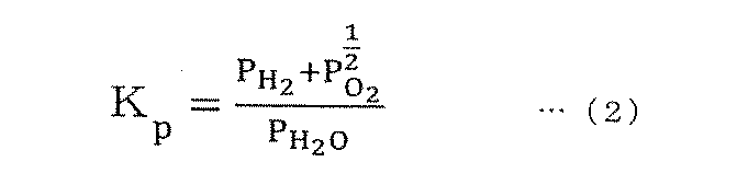
次に、以下の式(2)から、主に温度から決定される平行定数Kpを満たすような各組成(ここでは、H2O、H2、O2)の分圧PH2o、分圧PH2、分圧PO2が決まり、分圧に基づきアノード排ガスの各組成の濃度(アノード排ガス濃度)が決まる。
このようにして、アノード排ガス濃度(アノード排ガスの組成)は、既知である原燃料の組成から、POX流量、発電電流値及びアノード排ガス温度に基づき推定することができる。
なお、アノード排ガスの濃度の推定は、必ずしも平衡組成を用いることに限定されるものではなく、例えば速度定数を用いた反応速度式を用いて推定してもよい。
また、アノード排ガスの濃度の推定は、上記のように平衡組成や反応速度式といった熱力学的な計算式で求めることができるが、必ずしもこれに限られず、実験による実機評価によって推定してもよい。
次にステップS130において、コントローラ5は、排気燃焼器41の燃焼ガスの燃焼温度が目標燃焼温度になるような目標燃料流量F_fuel[mol/s]を演算する。目標燃料流量F_fuelは、目標燃焼温度、アノード排ガス濃度、カソード排ガスの熱流に基づき演算することができる。
具体的には、燃料流量F_fuelは、エンタルピーを用いた以下の式(3)、(4)から求めることができる。式(3)、(4)におけるH_anodegas[W]はアノード排ガスの熱流(アノード排ガスのエンタルピー)、H_cathodegas[W]はカソード排ガスの熱流(カソード排ガスのエンタルピー)を意味する。また、F_exh[mol/s]は排気ガス流量、αは燃料とアノード排ガスの流量比、h_exh[W/mol/s]は燃焼ガスの単位流量当たりの熱流、h_anodegas[W/mol/s]はアノード排ガスの単位流量当たりの熱流を意味する。



カソードガス流量F_airは空気ブロア31から送り出される空気の流量である。前述のとおり、空気ブロア31から送り出される空気の流量はコントローラ5により制御することができるため、本実施形態においては、システムの運転状況に応じて任意に設定した所定値を用いる。
空気の比熱Cp_airは固定値である。また、昇温温度ΔTは、燃料電池スタック1から排出される発電反応後のカソード排ガスの温度(カソード排ガス温度)から大気温度を引いた値である。前述のとおり、本実施形態においては、カソード排ガス温度はシステムの運転状況に応じて任意に設定した所定値を用いる。
このように、本実施形態では、カソードガス流量F_air及び昇温温度ΔTはいずれも任意の設定値を用いる。また、空気の比熱Cp_airは固定値であるため、カソード排ガス熱流H_cathodegasは、システムの運転状況に応じて任意に設定される所定値が与えられる。
式(3)、(4)に戻り、排気ガス流量F_exh[mol/s]は、排気燃焼器41で燃焼された後のガス流量である。排気ガス流量F_exhは、カソードガス流量F_airと燃料タンク21から燃料供給通路20に供給される燃料流量とから決定され、ここでは例えば完全燃焼を前提に計算される。前述のとおり、カソードガス流量F_airは、本実施形態においては、システムの運転状況に応じて任意に設定した所定値を用いる。ここでの燃料流量は、本実施形態においては目標燃料流量F_fuel(本ステップにおいて算出される対象)を用いる。
燃焼ガスの単位流量当たりの熱流h_exh[W/mol/s]は、ステップS120で推定したアノード排ガス濃度と、排気燃焼器41の燃焼ガスの目標温度(目標燃焼温度)とに基づき、完全燃焼を前提に推定することができる。
アノード排ガスの熱流H_anodegas[W]は、上記の式(3)を演算することにより推定される。但し本実施形態においては、排気ガス流量F_exhの中に算出する対象である目標燃料流量F_fuelが入った形の式になる。
燃料とアノード排ガスの流量比αは、燃料タンク21から燃料供給通路20に供給される燃料流量と燃料電池スタック1のスタック出口におけるアノード排ガスの流量との比である。燃料流量は、本実施形態においては目標燃料流量F_fuel(本ステップにおいて算出される対象)を用いる。アノード排ガスの流量は、ステップS120で推定したアノード排ガス濃度から推定することができる。
アノード排ガスの単位流量当たりの熱流h_anodegasは、アノード排ガス温度と、ステップS120で推定したアノード排ガス濃度とから推定することができる。本実施形態においては、アノード排ガス温度は、ステップS110と同様に任意に設定した所定値を用いる。
このように目標燃料流量F_fuelは、式(3)で推定されるアノード排ガスの熱流H_anodegasに基づき、式(4)を用いて推定することができる。
なお目標燃料流量F_fuel[mol/s]は、必ずしもエンタルピーを用いた式(3)、(4)から求める必要はない。例えばアノード排ガス濃度f_anodegas、排気ガス流量F_exh[mol/s]、排気ガスの比熱Cp_exh及び目標燃焼温度と混合ガス温度の差ΔTを用いた以下の式(6)から求めることもできる。

式(6)において、アノード排ガス濃度f_anodegasは、ステップS120において推定された値が用いられる。
排気ガス流量F_exhは式(3)と同様に、排気燃焼器41で燃焼された後のガス流量であり、完全燃焼を前提にカソードガス流量F_airと燃料流量とから計算される。前述のとおり、カソードガス流量F_airは、本実施形態においてはシステムの運転状況に応じて任意に設定した所定値を用いる。
排気ガスの比熱Cp_exhは排気燃焼器41で燃焼された後のガス組成から決まる固定値である。ガス組成は原燃料から推定することができる。
ΔTは、排気燃焼器41における燃焼ガス温度の目標値(目標燃焼温度)と、燃料電池スタック1の出口におけるアノード及びカソード排ガスの混合ガスの温度(混合ガス温度)との差である。目標燃焼温度はシステムの運転状況により設定され、本システムはこの排気燃焼器41がこの目標燃焼温度になるように制御を行う。本実施形態においては、前述のとおりアノード排ガス温度とカソード排ガス温度を同値と推定し、混合ガス温度は、カソード排ガス温度として運転状況に応じて任意に設定される所定値を用いる。
このように目標燃料流量F_fuelは、ステップS120で推定されるアノード排ガス濃度(アノード排ガスの組成)に基づき、式(6)を用いて推定することもできる。
コントローラ5は、ステップS130において目標燃料流量F_fuelを演算すると、ステップS140において、演算された目標燃料流量F_fuelに基づいて燃料タンク21から燃料供給通路20に原燃料を供給するように制御を行う。
ステップS140において目標燃料流量F_fuelに従って原燃料の供給が行われると、燃料電池システム100は再び燃焼ガス温度制御を開始し、ステップS110に戻る。
上記した第1実施形態の燃料電池システム100によれば、以下の効果を得ることができる。
燃料電池システム100においては、燃料電池スタック1の電流値及びPOX流量の少なくとも一方に基づきアノード排ガス濃度(アノード排ガスの組成)を推定する。そして推定されたアノード排ガス濃度に基づきポンプ及びインジェクタ23(燃料流量制御部)により原燃料の流量を調整することで排気燃焼器41(燃焼器)の温度を制御する。このように、燃料電池システム100においては、排気燃焼器41の燃焼ガス温度を検出する温度センサを用いずに、排気燃焼器41の温度を制御する。従って、燃焼ガス温度が高温になる場合でも排気燃焼器41の温度を制御することができる。
また、燃料電池システム100においては、原燃料ではなく、アノード排ガスの組成に基づき燃料流量(原燃料の流量)を調整することで排気燃焼器41(燃焼器)の温度を制御する。燃料電池システムにおいて、燃料は改質器において改質されたり、POX反応により酸素が供給されたりすることにより、組成や熱量が変化する。そのため、原燃料と排気燃焼器41に供給されるアノード排ガスとでは組成や熱量が異なる。従って、原燃料の組成に基づき燃料流量を調整することで燃焼器の温度を制御する場合、燃焼器の温度を精度よく制御することができない。これに対し、本実施形態の燃料電池システム100においては、アノード排ガスの組成を推定し、推定されたアノード排ガスの組成に基づき燃料流量を調整することで排気燃焼器41(燃焼器)の温度を制御している。このため、原燃料の組成に基づき燃料流量を調整する場合に比べて排気燃焼器41の温度を精度よく制御することができる。従って、燃焼ガス温度の過大による燃焼触媒劣化(例えば、シンタリング)や、燃焼ガス温度の過小による燃料電池の起動性、発電性能の悪化などを防止することができる。
(第2実施形態)
図3を参照して、第2実施形態の燃料電池システム100を説明する。なお、第1実施形態と同様の要素には同一の符号を付し、その説明を省略する。
図3を参照して、第2実施形態の燃料電池システム100を説明する。なお、第1実施形態と同様の要素には同一の符号を付し、その説明を省略する。
本実施形態では、アノード排ガス濃度(アノード排ガスの組成)の推定にアノードガス温度(改質された原燃料の温度)を用いる場合がある点、アノード排ガス濃度の推定に用いるアノード排ガス温度に検出値を用いる点が第1実施形態と異なる。
図3は第2実施形態による燃料電池システム100の燃焼ガス温度制御を説明するフローチャートである。なお、以下の制御はいずれもコントローラ5により実行される。
燃料電池システム100が燃焼ガス温度制御を開始すると、ステップS210においてコントローラ5は、アノード排ガス温度、発電電流値、POX流量及びアノードガス温度(改質された原燃料の温度)を取得する。
アノード排ガス温度はアノード排ガス通路42に設けられた温度センサ401(アノード排ガス温度検出手段)によって検出される。検出値の信号はコントローラ5に送信され、コントローラ5はこれを受信する。
発電電流値は、燃料電池スタック1に設けられた電流センサ101により検出された検出値、またはシステムの運転状況によって設定される発電電流の目標値である。コントローラ5は検出値の信号を受信する、または設定された目標値を発電電流として取得する。
POX流量はPOX配管32に設けられた流量センサ302により検出される検出値、またはカソードガス流量、スロットル321の開度及びPOX配管32による圧損から推定される推定値である。コントローラ5は検出値の信号を受信、または設定された目標値をPOX流量として取得する。
アノードガス温度は、改質器26から燃料電池スタック1に供給される改質された原燃料(カソードガス)の温度である。アノードガス温度は改質器26と燃料電池スタック1との間の位置に設けられた温度センサ202(改質ガス温度検出手段)により検出される。検出値は信号としてコントローラ5に送信され、コントローラ5はこれを受信する。
次にステップS220において、コントローラ5は、ステップS210で取得されたアノード排ガス温度とアノードガス温度との差ΔTを演算する。
続いてステップS230において、アノード排ガス温度とアノードガス温度との差ΔTが所定の値T_pre以上であるか否かを判定する。所定の値T_preは、アノード排ガスの組成が改質器26の温度に依存した組成になるような場合の改質器26と燃料電池スタック1との温度差の最小値である。
起動時などの暖機運転時において、改質器26のような燃料電池スタック1よりも小さい装置は燃料電池スタック1よりも早く暖機される。従って、暖機運転時は一定時間が経過するまでは燃料電池スタック1が低温、改質器26が高温という状態になる。この場合、燃料電池スタック1の温度(≒アノード排ガス温度)と改質器26の温度(≒アノードガス温度)との差ΔTは大きい。この状態においては、燃料電池スタック1における触媒が機能せず、アノード排ガスの組成は改質器26の温度に依存した組成となる。一方、燃料電池スタック1が一定温度に到達した後は、燃料電池スタック1の温度(≒アノード排ガス温度)と改質器26の温度(≒アノードガス温度)との差ΔTは小さくなり、アノード排ガスの組成は燃料電池スタック1の温度に依存した組成となる。
従って、アノード排ガス温度とアノードガス温度との差ΔTが所定の値T_pre以上である場合、アノード排ガスの組成は改質器26の温度(≒アノードガス温度)に依存した組成になる。一方、ΔTが所定の値T_preよりも小さい場合、アノード排ガスの組成は燃料電池スタック1の温度(≒アノード排ガス温度)に依存した組成になる。
ステップS230において、コントローラ5は、ΔTが所定の値T_pre以上であると判定すると、ステップS240に進む。
ステップS240において、コントローラ5は、S210において取得された発電電流値、POX流量及びアノードガス温度に基づき、アノード排ガス濃度(アノード排ガスの組成)を推定する。上記のとおり、ΔTが所定の値T_pre以上である場合は、アノード排ガスの組成は改質器26の温度(≒アノードガス温度)に依存した組成になるため、アノードガス温度に基づきアノードガス排ガス濃度を推定する。
具体的には、アノード排ガス濃度の推定は、原燃料の組成、燃料に供給される酸素の量及びアノードガス温度から、第1実施形態におけるステップS120と同様に、平衡組成や反応速度式を用いて行うことができる。また、実験による実機評価によって推定することもできる。なお、本実施形態では、アノード排ガス濃度の推定に用いられるアノード排ガス温度は、改質器26と燃料電池スタック1との間の位置に設けられた温度センサ202により検出された検出値が用いられる。
ステップS240においてアノード排ガス濃度を推定すると、コントローラ5は、ステップS260に進む。
一方、コントローラ5は、ステップS230においてアノード排ガス温度とアノードガス温度との差ΔTが所定の値T_preよりも小さいと判定すると、ステップS250に進む。
ステップS250において、コントローラ5は、S210において取得されたアノード排ガス温度、発電電流値、POX流量に基づき、アノード排ガス濃度(アノード排ガスの組成)を推定する。なお、本実施形態では、アノード排ガス濃度の推定に用いられるアノード排ガス温度は、アノード排ガス通路42に設けられたセンサ401により検出された検出値が用いられる。従って、アノード排ガス温度を任意の所定値とおく場合に比べ、アノード排ガス濃度をより精度よく推定することができる。
アノード排ガス濃度の推定は、第1実施形態におけるステップS120と同様に、平衡組成や反応速度式を用いて行うことができる。また、実験による実機評価によって推定することもできる。
ステップS250においてアノード排ガス濃度を推定すると、コントローラ5は、ステップS260に進む。
ステップS260において、コントローラ5は、排気燃焼器41の燃焼ガスの燃焼温度が目標燃焼温度になるような目標燃料流量F_fuelを演算する。目標燃料流量F_fuelは、第1実施形態におけるステップS130と同様に、例えば目標燃焼温度、アノード排ガス濃度、カソード排ガスの熱流に基づき演算される。
ステップS260において目標燃料流量F_fuelを演算すると、コントローラ5は、ステップS270において、演算された目標燃料流量F_fuelに基づいて燃料タンク21から燃料供給通路20に原燃料を供給するように制御を行う。
ステップS270において目標燃料流量F_fuelに従って原燃料の供給が行われると、燃料電池システム100は再び燃焼ガス温度制御を開始し、ステップS210に戻る。
上記した第2実施形態の燃料電池システム100によれば、さらに以下の効果を得ることができる。
本実施形態の燃料電池システム100においては、温度センサ401(アノード排ガス温度検出手段)により検出されたアノード排ガス温度と、発電電流値(電流値)と、POX流量とに基づきアノード排ガス濃度(アノード排ガスの組成)を推定する。従って、アノード排ガス温度に任意設定された所定値を用いる場合に比べ、アノード排ガス濃度の推定精度を高めることができる。これにより、アノード排ガス濃度に基づく燃焼器の温度制御の精度がより高まり、燃焼ガス温度の過大による燃焼触媒劣化(例えば、シンタリング)や、燃焼ガス温度の過小による燃料電池の起動性、発電性能の悪化などをより確実に防止することができる。
また、本実施形態の燃料電池システム100においては、アノード排ガス温度とアノードガス温度(改質された原燃料の温度)との差が所定の値T_pre以上の場合には、アノードガス温度と、電流値と、POX流量に基づきアノード排ガスの組成を推定する。燃料電池スタック1の温度(≒アノード排ガス温度)と改質器26の温度(≒アノードガス温度)との差ΔTが所定の値T_pre以上の場合、燃料電池スタック1における触媒が機能せず、アノード排ガスの組成は改質器26の温度に依存した組成となる。そのため、本実施形態では、アノード排ガス温度とアノードガス温度との差が所定の値T_pre以上の場合には、アノードガス温度に基づきアノード排ガスの組成を推定している。これにより、暖機運転時のように燃料電池スタック1が低温状態にある際にも、燃焼ガス温度を精度よく制御することができる。
(第3実施形態)
図4を参照して、第3実施形態の燃料電池システム100を説明する。なお、第1実施形態及び第2実施形態と同様の要素には同一の符号を付し、その説明を省略する。
図4を参照して、第3実施形態の燃料電池システム100を説明する。なお、第1実施形態及び第2実施形態と同様の要素には同一の符号を付し、その説明を省略する。
本実施形態では、燃料流量の検出値とアノード排ガスの組成とに基づきアノード排ガスの熱流を推定する点が他の実施形態と異なる。
図4は第3実施形態による燃料電池システム100の燃焼ガス温度制御を説明するフローチャートである。なお、以下の制御はいずれもコントローラ5により実行される。
ステップS310においてアノード排ガス温度、発電電流値、POX流量を取得し、ステップS320においてアノード排ガス濃度を推定する点は第1実施形態におけるステップS110及びステップS120と同様である。
ステップ330において、コントローラ5は、燃料流量を取得する。燃料流量は燃料タンク21から燃料供給通路20に供給される燃料の流量である。燃料流量は、燃料供給通路20における燃料タンク21と分岐通路22との間の位置に設けられた流量センサ201により検出される。検出値は信号としてコントローラ5に送信され、コントローラ5は、これを受信する。
ステップ340において、コントローラ5は、ステップS320において推定したアノード排ガス濃度と、ステップS330において取得した燃料流量とに基づき、アノード排ガス熱流を推定する。アノード排ガス熱流の推定は、例えば以下に示すように、エンタルピーを用いて計算できる。
例えば、メタンの水蒸気改質を考えると、以下の化学反応式(式(7))が与えられる。なお、式(7)において、a,b,c,dは各組成の濃度を示す。

ステップS320において、アノード排ガス濃度(a,b,c,d)は推定されている。またステップS330において、燃料流量(CH4とH2Oの総量)が取得されているため、物質収支から各組成の流量を推定できる。その結果、各組成の単位流量当たりのエンタルピーを推定でき、以下の式(8)に示すとおり、各組成の単位流量当たりのエンタルピーの合計からアノード排ガスの熱流(アノード排ガスのエンタルピー)H_anodegas[W]を推定できる。なお、式(8)におけるh_CO、h_CO2、h_H2、h_H2Oはそれぞれ単位流量当たりのCO、CO2、H2、H2Oのエンタルピー[W/mol/s]を示す。

なお、アノード排ガスの熱流H_anodegas[W]は、各組成の比熱を用いて推定してもよい。
次にステップS350において、コントローラ5は、第1実施形態と同様に排気燃焼器41の燃焼ガスの燃焼温度が目標燃焼温度になるような目標燃料流量F_fuel[mol/s]を演算する。ここで、アノード排ガスの熱流は、すでにステップS340にて推定されているため、目標燃料流量F_fuelは式(4)のみを用いて決定することができる。
なお、燃料とアノード排ガスの流量比αにおける燃料流量は、ステップS330において取得された流量センサ201の検出値を用いることができる。
コントローラ5は、ステップS350において目標燃料流量F_fuelを演算すると、ステップS360において、演算された目標燃料流量F_fuelに基づいて燃料タンク21から燃料供給通路20に原燃料を供給するように制御を行う。
ステップS360において目標燃料流量F_fuelに従って原燃料の供給が行われると、燃料電池システム100は再び燃焼ガス温度制御を開始し、ステップS310に戻る。
このように本実施形態では、目標燃料流量F_fuelは、アノード排ガス濃度と燃料流量とに基づき推定されるアノード排ガスの熱流に基づき決定される。
上記した第3実施形態の燃料電池システム100によれば、さらに以下の効果を得ることができる。
本実施形態の燃料電池システム100においては、燃料流量(原燃料の流量)を検出し、アノード排ガス温度と、電流値と、POX流量とに基づき推定されるアノード排ガス濃度(アノード排ガスの組成)と燃料流量の検出値とに基づきアノード排ガス熱流を推定する。そして推定したアノード排ガス熱流に基づき燃料流量制御部により原燃料の流量を調整することで燃焼器の温度を制御する。このように、燃料流量の検出値を用いて推定したアノード排ガス熱流に基づき原燃料の流量を調整するため、燃焼器の温度制御の精度がより高まる。従って、燃焼ガス温度の過大による燃焼触媒劣化(例えば、シンタリング)や、燃焼ガス温度の過小による燃料電池の起動性、発電性能の悪化などをより確実に防止することができる。
(第4実施形態)
図5を参照して、第4実施形態の燃料電池システム100を説明する。なお、他の実施形態と同様の要素には同一の符号を付し、その説明を省略する。
図5を参照して、第4実施形態の燃料電池システム100を説明する。なお、他の実施形態と同様の要素には同一の符号を付し、その説明を省略する。
本実施形態では、カソードガスの流量、カソード排ガス温度を検出し、これら検出値に基づきカソードガス熱量を推定する点が他の実施形態と異なる。
図5は第4実施形態による燃料電池システム100の燃焼ガス温度制御を説明するフローチャートである。なお、以下の制御はいずれもコントローラ5により実行される。
燃料電池システム100が燃焼ガス温度制御を開始すると、ステップS410においてコントローラ5は、カソードガス流量、カソード排ガス温度を取得する。
カソードガス流量は空気供給通路30に設けられた流量センサ301により検出される。検出値は信号としてコントローラ5に送信され、コントローラ5はこれを受信する。
カソード排ガス温度はカソード排ガス通路43に設けられた温度センサ402(カソード排ガス温度検出手段)により検出される。検出値は信号としてコントローラ5に送信され、コントローラ5はこれを受信する。なお、カソード排ガス温度は検出値を用いることが好ましいが、システムの運転状況に応じて任意に設定される所定値を用いてもよい。
次にステップS420において、コントローラ5は、ステップS410において取得したカソードガス流量、カソード排ガス温度に基づいてカソード排ガス熱流H_cathodegas[W]を推定する。
カソード排ガス熱流H_cathodegas[W]の推定は、カソードガス流量F_air[mol/s]、空気の比熱Cp_air及び昇温温度ΔTを用いた前述の式(5)から求めることができる。但しここでは、カソードガス流量F_airはステップS410で取得された流量センサ301の検出値が用いられる。また、昇温温度ΔTは、カソード排ガス温度から大気温度を引いた値であるが、カソード排ガス温度は、ステップS410で取得された温度センサ402の検出値が用いられる。
なお、昇温温度ΔTの計算におけるカソード排ガス温度は温度センサ402の検出値を用いることが好ましいが、必ずしもこれに限られない。例えばシステムの運転状況に応じて任意に設定される所定値を用いてもよく、また、アノード排ガス温度を検出する温度センサ401の検出値を用いてもよい。
また、カソード排ガス熱流H_cathodegas[W]の推定は、アノード排ガス熱流H_anodegas[W]と同様にエンタルピーから求めることもできる。具体的には、カソードガス流量F_air[mol/s]及びカソード排ガスの単位流量当たりの熱流h_cathodegas[W/mol/s]を用いた以下の式(9)から求めることができる。

カソードガス流量F_air[mol/s]はステップS410で取得された流量センサ301の検出値が用いられる。
カソード排ガスの単位流量当たりの熱流h_cathodegas[W/mol/s]は、カソード排ガスの温度及びカソードガス流量から推定できる。カソードガス排ガスの温度及びカソードガス流量は、それぞれステップS410で取得された温度センサ402の検出値及び流量センサ301の検出値を用いることができる。
ステップS420においてカソード排ガス熱流H_cathodegas[W]を推定すると、コントローラ5は、ステップS430において第1実施形態のステップS110と同様にアノード排ガス温度、発電電流値、POX流量を取得する。
次にステップS440において、コントローラ5は、第1実施形態のステップS120と同様にアノード排ガス濃度を推定する。
次にステップS450において、コントローラ5は、ステップS130と同様に、目標燃焼温度、アノード排ガス濃度、カソード排ガスの熱流に基づき、排気燃焼器41の燃焼ガスの燃焼温度が目標燃焼温度になるような目標燃料流量F_fuel[mol/s]を演算する。但し、本実施形態においては、カソード排ガスの熱流H_cathodegasは、所定値を与えるのではなく、ステップS420において検出値から推定した値を用いる。このように検出値から推定したカソード排ガスの熱流H_cathodegasに基づき目標燃料流量F_fuelを演算するため、排気燃焼器41の温度制御の精度がさらに高まる。
なお、目標燃料流量F_fuelは、第3実施形態のようにアノード排ガス濃度と燃料流量の検出値とに基づきアノード排ガス熱流H_anodegas[W]を推定し、この推定されたアノード排ガス熱流H_anodegasを用いて演算してもよい。即ちステップS420において推定されるカソード排ガスの熱流H_cathodegasと、アノード排ガス濃度と燃料流量の検出値とに基づき推定されるアノード排ガス熱流H_anodegasとに基づいて目標燃料流量F_fuelを演算してもよい。
コントローラ5は、ステップS450において目標燃料流量F_fuelを演算すると、ステップS460において、演算された目標燃料流量F_fuelに基づいて燃料タンク21から燃料供給通路20に原燃料を供給するように制御を行う。
ステップS460において目標燃料流量F_fuelに従って原燃料の供給が行われると、燃料電池システム100は再び燃焼ガス温度制御を開始し、ステップS410に戻る。
上記した第4実施形態の燃料電池システム100によれば、さらに以下の効果を得ることができる。
本実施形態の燃料電池システム100においては、カソードガス流量の検出値に基づきカソードガス熱流を推定し、推定されたカソードガス熱流と、アノード排ガスの組成とに基づき原燃料の流量を制御することで排気燃焼器41の温度を制御する。このようにカソードガス流量の検出値に基づき推定したカソード排ガスの熱流に基づき原燃料の流量を制御するため、燃焼器の温度制御の精度がさらに高まる。従って、燃焼ガス温度の過大による燃焼触媒劣化(例えば、シンタリング)や、燃焼ガス温度の過小による燃料電池の起動性、発電性能の悪化などをより確実に防止することができる。
また、本実施形態の燃料電池システム100においては、カソード排ガス温度の検出値に基づきカソードガス熱流を推定する。そして推定されたカソードガス熱流と、アノード排ガスの組成とに基づき原燃料の流量を制御することで排気燃焼器41(燃焼器)の温度を制御する。このようにカソード排ガス温度の検出値に基づき推定したカソード排ガスの熱流に基づき原燃料の流量を制御するため、排気燃焼器41の温度制御の精度がさらに高まる。従って、燃焼ガス温度の過大による燃焼触媒劣化(例えば、シンタリング)や、燃焼ガス温度の過小による起動性、発電性能の悪化などをより確実に防止することができる。
(第5実施形態)
図6を参照して、第5実施形態の燃料電池システム100を説明する。なお、他の実施形態と同様の要素には同一の符号を付し、その説明を省略する。
図6を参照して、第5実施形態の燃料電池システム100を説明する。なお、他の実施形態と同様の要素には同一の符号を付し、その説明を省略する。
本実施形態では、カソード排ガス熱流を推定する際に、発電時の酸素移動を加味する点が他の実施形態と異なる。
図6は第5実施形態による燃料電池システム100の燃焼ガス温度制御を説明するフローチャートである。なお、以下の制御はいずれもコントローラ5により実行される。
燃料電池システム100が燃焼ガス温度制御を開始すると、ステップS510においてコントローラ5は、カソードガス流量、カソード排ガス温度及び発電電流値を取得する。
第4実施形態と同様に、コントローラ5は、流量センサ301による検出値からカソードガス流量を取得し、温度センサ402による検出値からカソード排ガス温度を取得する。
発電電流値は燃料電池スタック1に設けられた電流センサ101により検出される。検出値は信号としてコントローラ5に送信され、コントローラ5はこれを受信する。なお、発電電流値は検出値を用いることが好ましいが、システムの運転状況に応じて設定される発電電流の目標値を用いてもよい。
次にステップS520において、コントローラ5は、ステップS510において取得したカソードガス流量、カソード排ガス温度、発電電流値に基づいてカソード排ガス熱流H_cathodegas[W]を推定する。
他の実施形態では、カソード排ガス熱流H_cathodegasの推定に式(5)を用いていたが、本実施形態においては、さらに発電時の酸素移動を加味した以下の式(10)を用いる。なお、式(10)のIは発電電流値、αは変換係数(電流から酸素への変換)、Cp_O2は酸素比熱である。式(10)においては、式(5)の左辺から発電による酸素移動分だけ熱流の値が減じられている。

Iは燃料電池スタック1で発電される発電電流値であり、ステップS510において取得された電流センサ101による検出値を用いる。変換係数α及び酸素比熱Cp_O2は固定値である。
このように、式(10)では、発電時の酸素移動による熱流の変化を加味して、燃料電池スタック1で発電される電流値とカソードガス流量とに基づきカソード排ガス熱流H_cathodegasを推定する。発電時の酸素移動による熱流の変化を加味することで、カソード排ガス熱流の推定精度がより高まる。
なお、カソード排ガス熱流H_cathodegas[W]の推定は、本実施形態においてもエンタルピーから求めることもできる。具体的には、式(9)の右辺から発電による酸素移動による熱量を減じればよい。
ステップS520においてカソード排ガス熱流H_cathodegas[W]を推定すると、コントローラ5は、ステップS530において第1実施形態のステップS110と同様にアノード排ガス温度、発電電流値、POX流量を取得する。
次にステップS540において、コントローラ5は、ステップS120と同様にアノード排ガス濃度を推定し、ステップS550において、ステップS130と同様に目標燃料流量F_fuelを演算する。
続いてステップS560において、コントローラ5は、目標燃料流量F_fuelに基づいて原燃料を供給し、原燃料の供給が行われると、燃料電池システム100は再び燃焼ガス温度制御を開始し、ステップS510に戻る。
上記した第5実施形態の燃料電池システム100によれば、さらに以下の効果を得ることができる。
本実施形態の燃料電池システム100においては、カソードガス流量の検出値と、燃料電池スタック1で発電される電流値に基づきカソードガス熱流を推定する。そして推定されたカソードガス熱流と、アノード排ガスの組成とに基づき原燃料の流量を制御することで排気燃焼器41(燃焼器)の温度を制御する。このように電流値に基づきカソードガス熱流を推定するため、発電時の酸素移動による熱流の変化が加味され、カソード排ガス熱流の推定精度がより高まる。排気燃焼器41の温度は、推定したカソード排ガスの熱流に基づき原燃料の流量を制御することで制御されるため、排気燃焼器41の温度制御の精度も高まる。従って、燃焼ガス温度の過大による燃焼触媒劣化(例えば、シンタリング)や、燃焼ガス温度の過小による燃料電池の起動性、発電性能の悪化などをさらに確実に防止することができる。
(第6実施形態)
図7を参照して、第6実施形態の燃料電池システム100を説明する。なお、他の実施形態と同様の要素には同一の符号を付し、その説明を省略する。
図7を参照して、第6実施形態の燃料電池システム100を説明する。なお、他の実施形態と同様の要素には同一の符号を付し、その説明を省略する。
本実施形態では、排気燃焼器41からの放熱量を加味する点が他の実施形態と異なる。
図6は第5実施形態による燃料電池システム100の燃焼ガス温度制御を説明するフローチャートである。なお、以下の制御はいずれもコントローラ5により実行される。
燃料電池システム100が燃焼ガス温度制御を開始すると、ステップS610においてコントローラ5は、アノード排ガス温度、発電電流値、POX流量、燃焼器放熱量を取得する。
アノード排ガス温度、発電電流値、POX流量は他の実施形態と同様の方法で取得する。
燃焼器放熱量は排気燃焼器41から外部に放熱される熱量であり、一般的な熱交換の式や、実験による実機評価の結果により決定することができる。
例えば燃焼器放熱量Q_heat[W]は、以下の式(11)から決定することができる。但し、式(11)において、hは排気燃焼器41の熱抵抗[K/W]、Aは排気燃焼器41の表面積、T_targetは目標燃焼温度、T_outsideは外気温を表す。

ステップS610においてアノード排ガス温度、発電電流値、POX流量、燃焼器放熱量を取得すると、コントローラ5は、ステップS620において、アノード排ガス濃度(アノード排ガス組成)を推定する。他の実施形態と同様にアノード排ガス濃度は、アノード排ガス温度、発電電流値、POX流量に基づき、原燃料の組成、燃料に供給される酸素の量及びアノード排ガス温度から推定することができる。
次にステップS630において、コントローラ5は、排気燃焼器41の燃焼ガスの燃焼温度が目標燃焼温度になるような目標燃料流量F_fuel[mol/s]を演算する。目標燃料流量F_fuelは、アノード排ガス濃度及び燃焼器放熱量に基づき、例えば以下の式(12)から求めることができる。

式(12)は、式(6)の左辺から燃焼器放熱量Q_heat[W]を引いたもので、燃焼器放熱量Q_heatを加味して目標燃料流量F_fuelが決定される。
上記した第6実施形態の燃料電池システム100によれば、さらに以下の効果を得ることができる。
本実施形態の燃料電池システム100においては、アノード排ガス濃度と、排気燃焼器41からの外部への放熱量とに基づき原燃料の流量を制御することで排気燃焼器41の温度を制御している。即ち、排気燃焼器41を目標温度に制御するための目標燃料流量を算出する際に、排気燃焼器41からの外部への放熱量を加味する。従って、放熱量を考慮せずに算出した目標燃料流量によって排気燃焼器41の温度を制御する場合に比べ、排気燃焼器41の温度をより精度よく制御することができる。従って、燃焼ガス温度の過大による燃焼触媒劣化(例えば、シンタリング)や、燃焼ガス温度の過小による燃料電池の起動性、発電性能の悪化などをより確実に防止することができる。
以上、本発明の実施形態について説明したが、上記実施形態は本発明の適用例の一部を示したに過ぎず、本発明の技術的範囲を上記実施形態の具体的構成に限定する趣旨ではない。
上記した各実施形態は、それぞれ単独の実施形態として説明したが、適宜組み合わせてもよい。
Claims (9)
- 燃料電池スタックと、原燃料を改質して前記燃料電池スタックに供給する改質器と、前記改質器に供給する前記原燃料の流量を制御する燃料流量制御部と、前記原燃料に酸素を供給する空気供給管と、前記燃料電池スタックから排出されるカソード排ガスとアノード排ガスとを混合して燃焼させる燃焼器と、を備える燃料電池システムの制御方法であって、
前記燃料電池スタックで発電される電流値及び前記空気供給管から供給される酸素供給量の少なくとも一方を検出し、
前記電流値及び前記酸素供給量の少なくとも一方に基づき前記アノード排ガスの組成を推定し、
前記推定されたアノード排ガスの組成に基づき前記燃料流量制御部により前記原燃料の流量を調整することで前記燃焼器の温度を制御する、
燃料電池システムの制御方法。 - 請求項1に記載の燃料電池システムの制御方法であって、
前記燃料電池スタックから排出される前記アノード排ガスの温度をさらに検出し、
前記アノード排ガス温度と、前記電流値と、前記酸素供給量とに基づき前記アノード排ガスの組成を推定する、
燃料電池システムの制御方法。 - 請求項1に記載の燃料電池システムの制御方法であって、
前記燃料電池スタックから排出される前記アノード排ガスの温度と、前記燃料電池スタックに供給される改質された原燃料の温度とをさらに検出し、
前記アノード排ガスの温度と前記改質された原燃料の温度との差が所定の値以上の場合には、前記改質された原燃料の温度と、前記電流値と、前記酸素供給量とに基づき前記アノード排ガスの組成を推定し、
前記アノード排ガスの温度と前記改質された原燃料の温度との差が所定の値よりも小さい場合には、前記アノード排ガス温度と、前記電流値と、前記酸素供給量とから前記アノード排ガスの組成を推定する、
燃料電池システムの制御方法。 - 請求項1から3のいずれか一つに記載の燃料電池システムの制御方法であって、
前記原燃料の流量をさらに検出し、
前記原燃料の流量と、前記アノード排ガスの組成とに基づき、アノード排ガス熱流を推定し、
前記アノード排ガス熱流に基づき前記燃料流量制御部により前記原燃料の流量を調整することで前記燃焼器の温度を制御する、
燃料電池システムの制御方法。 - 請求項1から4のいずれか一つに記載の燃料電池システムの制御方法であって、
前記燃料電池スタックに供給されるカソードガスの流量をさらに検出し、
前記カソードガス流量に基づきカソードガス熱流を推定し、
前記推定されたカソードガス熱流と、前記アノード排ガスの組成とに基づき原燃料の流量を制御することで前記燃焼器の温度を制御する、
燃料電池システムの制御方法。 - 請求項5に記載の燃料電池システムの制御方法であって、
前記燃料電池スタックから排出されるカソード排ガスの温度をさらに検出し、
前記カソードガス流量と、前記カソード排ガス温度とに基づき、前記カソードガス熱流を推定する、
燃料電池システムの制御方法。 - 請求項5に記載の燃料電池システムの制御方法であって、
前記カソードガス流量と、前記燃料電池スタックで発電される電流値とに基づきカソードガス熱流を推定する、
燃料電池システムの制御方法。 - 請求項1から7のいずれか一つに記載の燃料電池システムの制御方法であって、
前記アノード排ガスの組成と、前記燃焼器からの外部への放熱量とに基づき前記原燃料の流量を制御することで前記燃焼器の温度を制御する、
燃料電池システムの制御方法。 - 燃料電池スタックと、
原燃料を改質して前記燃料電池スタックに供給する改質器と、
前記改質器に供給する前記原燃料の流量を制御する燃料流量制御部と、
前記原燃料に酸素を供給する空気供給管と、
前記燃料電池スタックから排出されるカソード排ガスとアノード排ガスとを混合して燃焼させる燃焼器と、
制御部と、を備える燃料電池システムであって、
前記燃料電池スタックで発電される電流値及び前記空気供給管から供給される酸素供給量の少なくとも一方を検出する検出手段と、をさらに備え、
前記制御部は、
前記電流値及び前記酸素供給量の少なくとも一方に基づき前記アノード排ガスの組成を推定し、
前記推定されたアノード排ガスの組成に基づき前記燃料流量制御部により前記原燃料の流量を調整することで前記燃焼器の温度を制御する、
燃料電池システム。
Priority Applications (5)
| Application Number | Priority Date | Filing Date | Title |
|---|---|---|---|
| CN201980094804.3A CN113632269B (zh) | 2019-03-27 | 2019-03-27 | 燃料电池系统和燃料电池系统的控制方法 |
| PCT/IB2019/000404 WO2020194019A1 (ja) | 2019-03-27 | 2019-03-27 | 燃料電池システム及び燃料電池システムの制御方法 |
| JP2021508337A JP7120445B2 (ja) | 2019-03-27 | 2019-03-27 | 燃料電池システム及び燃料電池システムの制御方法 |
| EP19921140.0A EP3951966B1 (en) | 2019-03-27 | 2019-03-27 | Fuel cell system and method for controlling fuel cell system |
| US17/442,978 US11721821B2 (en) | 2019-03-27 | 2019-03-27 | Fuel cell system and method for controlling fuel cell system |
Applications Claiming Priority (1)
| Application Number | Priority Date | Filing Date | Title |
|---|---|---|---|
| PCT/IB2019/000404 WO2020194019A1 (ja) | 2019-03-27 | 2019-03-27 | 燃料電池システム及び燃料電池システムの制御方法 |
Publications (1)
| Publication Number | Publication Date |
|---|---|
| WO2020194019A1 true WO2020194019A1 (ja) | 2020-10-01 |
Family
ID=72611636
Family Applications (1)
| Application Number | Title | Priority Date | Filing Date |
|---|---|---|---|
| PCT/IB2019/000404 Ceased WO2020194019A1 (ja) | 2019-03-27 | 2019-03-27 | 燃料電池システム及び燃料電池システムの制御方法 |
Country Status (5)
| Country | Link |
|---|---|
| US (1) | US11721821B2 (ja) |
| EP (1) | EP3951966B1 (ja) |
| JP (1) | JP7120445B2 (ja) |
| CN (1) | CN113632269B (ja) |
| WO (1) | WO2020194019A1 (ja) |
Cited By (2)
| Publication number | Priority date | Publication date | Assignee | Title |
|---|---|---|---|---|
| CN112290056A (zh) * | 2020-10-30 | 2021-01-29 | 武汉格罗夫氢能汽车有限公司 | 一种氢燃料电池的阴极空气供给系统控制方法 |
| JP2023178814A (ja) * | 2022-06-06 | 2023-12-18 | 日産自動車株式会社 | 燃料電池システムの制御方法、及び燃料電池システム |
Families Citing this family (1)
| Publication number | Priority date | Publication date | Assignee | Title |
|---|---|---|---|---|
| JP7800653B2 (ja) * | 2022-03-22 | 2026-01-16 | 日産自動車株式会社 | 燃料電池システム制御方法及び燃料電池システム |
Citations (6)
| Publication number | Priority date | Publication date | Assignee | Title |
|---|---|---|---|---|
| JP2008059877A (ja) * | 2006-08-31 | 2008-03-13 | Toyota Motor Corp | 燃料電池システム |
| JP2011034715A (ja) * | 2009-07-30 | 2011-02-17 | Nissan Motor Co Ltd | 燃料電池システムとこの燃料電池システムに用いる燃料電池の昇温方法 |
| JP2014207133A (ja) * | 2013-04-12 | 2014-10-30 | パナソニック株式会社 | 水素生成システムおよび燃料電池システム |
| JP2016111004A (ja) | 2014-11-28 | 2016-06-20 | パナソニックIpマネジメント株式会社 | 燃料電池システムの運転方法および燃料電池システムにおける燃料組成推定方法 |
| JP2017050049A (ja) * | 2015-08-31 | 2017-03-09 | 株式会社豊田自動織機 | 燃料電池システム |
| JP2018186079A (ja) * | 2017-04-21 | 2018-11-22 | パナソニックIpマネジメント株式会社 | 高温動作型燃料電池システム |
Family Cites Families (15)
| Publication number | Priority date | Publication date | Assignee | Title |
|---|---|---|---|---|
| JPS62234871A (ja) * | 1986-04-04 | 1987-10-15 | Hitachi Ltd | 燃料電池発電プラント |
| US6630109B2 (en) * | 1998-07-16 | 2003-10-07 | Toyota Jidosha Kabushiki Kaisha | Control apparatus for reformer and method of controlling reformer using control apparatus |
| US6306531B1 (en) | 1999-07-06 | 2001-10-23 | General Motors Corporation | Combustor air flow control method for fuel cell apparatus |
| JP4854848B2 (ja) * | 2000-12-22 | 2012-01-18 | 本田技研工業株式会社 | 加熱処理システムの制御方法 |
| JP4791698B2 (ja) * | 2004-03-19 | 2011-10-12 | 株式会社コロナ | 改質型燃料電池システム及び改質型燃料電池システムの運転制御方法 |
| KR20110096025A (ko) | 2008-12-01 | 2011-08-26 | 유티씨 파워 코포레이션 | 연료 전지 발전 장치의 애노드 이용률 제어 시스템 |
| EP2406844A1 (en) * | 2009-03-09 | 2012-01-18 | Toyota Jidosha Kabushiki Kaisha | Fuel cell system, control method for the fuel cell system, and state detection method for fuel cell |
| WO2013169329A2 (en) * | 2012-05-11 | 2013-11-14 | Ballard Power Systems Inc. | Method of operating a fuel cell power system |
| JP6459063B2 (ja) * | 2015-04-20 | 2019-01-30 | パナソニックIpマネジメント株式会社 | 固体酸化物形燃料電池システムの運転方法 |
| CN106910912B (zh) * | 2015-12-18 | 2020-06-30 | 通用电气公司 | 燃料电池系统及其操作方法及燃料电池发电厂 |
| WO2017110303A1 (ja) * | 2015-12-25 | 2017-06-29 | 日産自動車株式会社 | 燃料電池システム及びその制御方法 |
| CN108604693B (zh) * | 2015-12-25 | 2020-06-23 | 日产自动车株式会社 | 固体氧化物型燃料电池系统、固体氧化物型燃料电池系统的控制方法 |
| JP6452741B2 (ja) * | 2017-03-06 | 2019-01-16 | 東京瓦斯株式会社 | 燃料電池システム |
| CN111788731B (zh) * | 2018-03-07 | 2024-03-12 | 大阪瓦斯株式会社 | 燃料电池系统和燃料电池系统的运转方法 |
| CN109860660B (zh) * | 2019-01-28 | 2021-11-09 | 华中科技大学鄂州工业技术研究院 | 一种高效固体氧化物燃料电池系统 |
-
2019
- 2019-03-27 JP JP2021508337A patent/JP7120445B2/ja active Active
- 2019-03-27 WO PCT/IB2019/000404 patent/WO2020194019A1/ja not_active Ceased
- 2019-03-27 CN CN201980094804.3A patent/CN113632269B/zh active Active
- 2019-03-27 EP EP19921140.0A patent/EP3951966B1/en active Active
- 2019-03-27 US US17/442,978 patent/US11721821B2/en active Active
Patent Citations (6)
| Publication number | Priority date | Publication date | Assignee | Title |
|---|---|---|---|---|
| JP2008059877A (ja) * | 2006-08-31 | 2008-03-13 | Toyota Motor Corp | 燃料電池システム |
| JP2011034715A (ja) * | 2009-07-30 | 2011-02-17 | Nissan Motor Co Ltd | 燃料電池システムとこの燃料電池システムに用いる燃料電池の昇温方法 |
| JP2014207133A (ja) * | 2013-04-12 | 2014-10-30 | パナソニック株式会社 | 水素生成システムおよび燃料電池システム |
| JP2016111004A (ja) | 2014-11-28 | 2016-06-20 | パナソニックIpマネジメント株式会社 | 燃料電池システムの運転方法および燃料電池システムにおける燃料組成推定方法 |
| JP2017050049A (ja) * | 2015-08-31 | 2017-03-09 | 株式会社豊田自動織機 | 燃料電池システム |
| JP2018186079A (ja) * | 2017-04-21 | 2018-11-22 | パナソニックIpマネジメント株式会社 | 高温動作型燃料電池システム |
Non-Patent Citations (1)
| Title |
|---|
| See also references of EP3951966A4 |
Cited By (2)
| Publication number | Priority date | Publication date | Assignee | Title |
|---|---|---|---|---|
| CN112290056A (zh) * | 2020-10-30 | 2021-01-29 | 武汉格罗夫氢能汽车有限公司 | 一种氢燃料电池的阴极空气供给系统控制方法 |
| JP2023178814A (ja) * | 2022-06-06 | 2023-12-18 | 日産自動車株式会社 | 燃料電池システムの制御方法、及び燃料電池システム |
Also Published As
| Publication number | Publication date |
|---|---|
| EP3951966A1 (en) | 2022-02-09 |
| EP3951966A4 (en) | 2022-03-23 |
| US20220190368A1 (en) | 2022-06-16 |
| EP3951966B1 (en) | 2024-04-24 |
| CN113632269B (zh) | 2024-02-27 |
| CN113632269A (zh) | 2021-11-09 |
| JP7120445B2 (ja) | 2022-08-17 |
| US11721821B2 (en) | 2023-08-08 |
| JPWO2020194019A1 (ja) | 2020-10-01 |
Similar Documents
| Publication | Publication Date | Title |
|---|---|---|
| JP6627888B2 (ja) | 固体酸化物型燃料電池システム、固体酸化物型燃料電池システムの制御方法 | |
| KR100587518B1 (ko) | 연료전지 동력장치의 예열장치 | |
| JP4854848B2 (ja) | 加熱処理システムの制御方法 | |
| WO2020194019A1 (ja) | 燃料電池システム及び燃料電池システムの制御方法 | |
| JP5292173B2 (ja) | 燃料電池システム | |
| JP2017050049A (ja) | 燃料電池システム | |
| CN110959214B (zh) | 燃料电池系统及其控制方法 | |
| US11205792B2 (en) | Fuel cell system and control method for same | |
| US11069907B2 (en) | Fuel cell system and method for controlling fuel cell system | |
| CN114365313A (zh) | 燃料电池系统和燃料电池系统的控制方法 | |
| US12388096B2 (en) | Fuel cell system and control method for fuel cell system | |
| JP2020080262A (ja) | 燃料電池システム | |
| JP7102960B2 (ja) | 燃料電池システムの制御方法及び燃料電池システム | |
| JP2004296235A (ja) | 燃料電池用の改質装置 | |
| US11769887B2 (en) | Combustion system and combustion control method | |
| JP7353158B2 (ja) | 燃料電池システム | |
| JP2020047482A (ja) | 燃料電池システム | |
| JP2019079689A (ja) | 燃料電池システムおよび燃料電池システムの制御方法 | |
| JP6387525B2 (ja) | 水素生成装置およびそれを備える燃料電池システム | |
| JP6777237B2 (ja) | 燃料電池システムの制御方法、及び、燃料電池システム | |
| JP2026046814A (ja) | 燃料電池システム | |
| JP2001180904A (ja) | 燃料蒸発装置 | |
| WO2021116725A1 (ja) | 燃料電池システムの制御方法、及び燃料電池システム | |
| JP2019220366A (ja) | 燃料電池システムおよびその制御方法 | |
| JP2019033023A (ja) | 燃料電池システム及び燃料電池システムの制御方法 |
Legal Events
| Date | Code | Title | Description |
|---|---|---|---|
| 121 | Ep: the epo has been informed by wipo that ep was designated in this application |
Ref document number: 19921140 Country of ref document: EP Kind code of ref document: A1 |
|
| ENP | Entry into the national phase |
Ref document number: 2021508337 Country of ref document: JP Kind code of ref document: A |
|
| NENP | Non-entry into the national phase |
Ref country code: DE |
|
| ENP | Entry into the national phase |
Ref document number: 2019921140 Country of ref document: EP Effective date: 20211027 |