WO2020194511A1 - 電極カテーテル - Google Patents
電極カテーテル Download PDFInfo
- Publication number
- WO2020194511A1 WO2020194511A1 PCT/JP2019/012885 JP2019012885W WO2020194511A1 WO 2020194511 A1 WO2020194511 A1 WO 2020194511A1 JP 2019012885 W JP2019012885 W JP 2019012885W WO 2020194511 A1 WO2020194511 A1 WO 2020194511A1
- Authority
- WO
- WIPO (PCT)
- Prior art keywords
- arm members
- electrode
- catheter
- electrode unit
- catheter body
- Prior art date
- Legal status (The legal status is an assumption and is not a legal conclusion. Google has not performed a legal analysis and makes no representation as to the accuracy of the status listed.)
- Ceased
Links
Images


Classifications
-
- A—HUMAN NECESSITIES
- A61—MEDICAL OR VETERINARY SCIENCE; HYGIENE
- A61B—DIAGNOSIS; SURGERY; IDENTIFICATION
- A61B5/00—Measuring for diagnostic purposes; Identification of persons
- A61B5/24—Detecting, measuring or recording bioelectric or biomagnetic signals of the body or parts thereof
- A61B5/25—Bioelectric electrodes therefor
- A61B5/279—Bioelectric electrodes therefor specially adapted for particular uses
- A61B5/28—Bioelectric electrodes therefor specially adapted for particular uses for electrocardiography [ECG]
- A61B5/283—Invasive
- A61B5/287—Holders for multiple electrodes, e.g. electrode catheters for electrophysiological study [EPS]
-
- A—HUMAN NECESSITIES
- A61—MEDICAL OR VETERINARY SCIENCE; HYGIENE
- A61B—DIAGNOSIS; SURGERY; IDENTIFICATION
- A61B5/00—Measuring for diagnostic purposes; Identification of persons
- A61B5/24—Detecting, measuring or recording bioelectric or biomagnetic signals of the body or parts thereof
- A61B5/25—Bioelectric electrodes therefor
- A61B5/279—Bioelectric electrodes therefor specially adapted for particular uses
- A61B5/28—Bioelectric electrodes therefor specially adapted for particular uses for electrocardiography [ECG]
- A61B5/283—Invasive
-
- A—HUMAN NECESSITIES
- A61—MEDICAL OR VETERINARY SCIENCE; HYGIENE
- A61B—DIAGNOSIS; SURGERY; IDENTIFICATION
- A61B5/00—Measuring for diagnostic purposes; Identification of persons
- A61B5/68—Arrangements of detecting, measuring or recording means, e.g. sensors, in relation to patient
- A61B5/6846—Arrangements of detecting, measuring or recording means, e.g. sensors, in relation to patient specially adapted to be brought in contact with an internal body part, i.e. invasive
- A61B5/6847—Arrangements of detecting, measuring or recording means, e.g. sensors, in relation to patient specially adapted to be brought in contact with an internal body part, i.e. invasive mounted on an invasive device
- A61B5/6852—Catheters
- A61B5/6859—Catheters with multiple distal splines
-
- A—HUMAN NECESSITIES
- A61—MEDICAL OR VETERINARY SCIENCE; HYGIENE
- A61B—DIAGNOSIS; SURGERY; IDENTIFICATION
- A61B2560/00—Constructional details of operational features of apparatus; Accessories for medical measuring apparatus
- A61B2560/04—Constructional details of apparatus
- A61B2560/0462—Apparatus with built-in sensors
- A61B2560/0468—Built-in electrodes
Definitions
- the present invention relates to an electrode catheter suitable for mapping an electrically active state in the heart and measuring the electrocardiographic potential after ablation (cauterization) of the inner wall of the heart.
- Patent Document 1 As an electrode catheter for mapping the electrical activity in the heart, a catheter provided with a plurality of arm members radially protruding from the tip of the catheter body is known (Patent Document 1).
- a terminal electrode and a ring-shaped electrode are attached to each of the arm members in this electrode catheter, and the potential in the circular region having the longitudinal length of the arm member as the radius is measured at one time and simultaneously with one electrode catheter. can do.
- Patent Document 1 has a problem that the arm members are densely packed when the tip of the catheter rotates about the axis of the catheter body in a state where the arm members are in contact with some obstacle. As a result, it is no longer guaranteed that the potential measurements will be made in the intended circular region.
- the present invention has been made in view of the above circumstances, and an object of the present invention is to provide an electrode catheter capable of preventing unintended concentration of radially protruding arm members.
- the present invention is an electrode catheter including a catheter main body and an electrode unit attached to the tip of the catheter main body, and the electrode unit is one end portion in the longitudinal direction. Is supported by the catheter body, and a plurality of arm members whose other ends in the longitudinal direction project radially from the tip of the catheter body, electrodes attached to the arm members, and adjacent arm members. It is characterized by comprising a restraining means for restraining the movement of each other.
- the restraining means restrains the movement of adjacent arm members, it is possible to prevent unintended concentration of the arm members protruding radially.
- FIG. 3 is a vertical cross-sectional view showing a state in which the tip portion of the electrode catheter shown in FIG. 1 is cut along the line EE shown in FIG.
- A) and (b) are schematic views showing a state in which the electrode unit portion of the electrode catheter shown in FIG. 1 is deformed.
- A) and (b) are schematic views showing the electrode unit portion of the electrode catheter according to the modified embodiment of the present invention.
- FIG. 1 is a plan view showing a schematic configuration of an electrode catheter according to an embodiment of the present invention.
- the electrode catheter 1 is an instrument that is inserted into the heart through a blood vessel and is used for mapping an electrically active state in the heart and measuring an electrocardiographic potential after ablation (cautery) of the inner wall of the heart.
- the electrode catheter 1 includes a catheter body 10 extending in the longitudinal direction, an operation unit 20 attached to a proximal end portion 10b (proximal end side) of the catheter body 10, and a tip portion 10a (distal end side) of the catheter body 10. It is provided with an electrode unit 100 (100A) attached to the.
- the catheter body 10 is composed of a tubular member having at least one lumen 11 (see FIG. 4) extending in the longitudinal direction.
- a conducting wire (not shown) conducting with each of the ring-shaped electrodes 120, 120 ...
- Constituting the electrode unit 100 and a portion on the distal end side of the catheter body 10 are indicated by arrows B1-B2 in FIG.
- a pulling wire (not shown) or the like that bends (or deflects) in the direction is inserted.
- the catheter body 10 is made of a flexible material. Specifically, synthetic resins such as polyolefin, polyamide, polyether polyamide, polyurethane, nylon and PEBAX (registered trademark. Substance name: polyether blockamide) can be used for the catheter body 10.
- the outer diameter of the catheter body 10 is preferably 1.0 to 3.5 mm, more preferably 1.6 to 2.8 mm.
- the longitudinal length of the catheter body 10 is preferably 600 to 1500 mm, more preferably 900 to 1200 mm.
- the catheter body 10 may be provided with a lumen for perfusion in which the perfusate is ejected from the perfusion port 13 (see FIG. 3) provided at the tip thereof.
- the operation unit 20 is arranged closer to the catheter body 10 than the handle 21 gripped by the operator of the electrode catheter 1 and the catheter body 10, and deflects (or or deflects) the distal end side portion of the catheter body 10 in the directions of arrows B1-B2 in the drawing. It includes a rotary plate 22 for bending and deforming) and a rotary knob 23 for rotating the rotary plate 22.
- the rotating plate 22 is rotated in the direction of the arrow A1 in the drawing, the distal end side portion of the catheter body 10 is deflected in the direction of the arrow B1 in the drawing at an angle corresponding to the rotation angle of the rotating plate 22.
- the rotating plate 22 is rotated in the direction of arrow A2 in the drawing, the distal end side portion of the catheter body 10 is deflected in the direction of arrow B2 in the drawing at an angle corresponding to the rotation angle of the rotating plate 22.
- FIG. 2 is a perspective view showing a tip portion of the electrode catheter shown in FIG.
- FIG. 3 is a diagram showing a state in which the electrode unit portion of the electrode catheter shown in FIG. 1 is observed from the direction of arrow C in FIG.
- the electrode unit 100 100A
- one end 110a in the longitudinal direction is supported by the tip 10a of the catheter body 10
- the other end 110b in the longitudinal direction radially protrudes from the tip 10a of the catheter body 10.
- the arm members 110 110A to 110F
- the ring-shaped electrodes 120, 120 Attached to each arm member 110, and the core wire (constraining means) 130 (130A to 130F) that restrains the operation of the adjacent arm members 110, 110.
- the core wire (constraining means) 130 130A to 130F
- the six arm members 110A to 110F are arranged side by side in the circumferential direction about the axis D (axis D of the electrode catheter 1) extending along the longitudinal direction of the catheter body 10.
- the electrode unit 100A includes six core wires 130A to 130F.
- One core wire 130 connects between two arm members 110 and 110 adjacent to each other in the circumferential direction, and more specifically, between the other ends (between tips) of the two arm members 110 and 110. That is, the electrode unit 100A has the same number of core wires 130 as the arm member 110.
- FIG. 4 is a vertical cross-sectional view showing a state in which the tip portion of the electrode catheter shown in FIG. 1 is cut along the line EE shown in FIG.
- the arm member 110 (110A, 110B ) Includes a covering tube 111 (111A, 111B ”) With hollow holes 112 (112A, 112B ”) Extending along the longitudinal direction.
- the covering tube 111 is made of a flexible material. Specifically, synthetic resins such as polyolefin, polyamide, polyether polyamide, polyurethane, nylon and PEBAX (registered trademark. Substance name: polyether blockamide) can be used for the coating tube 111.
- the covering tube 111 is fixed to the tip portion 10a of the catheter body 10 by a method such as fusion.
- the outer diameter of the arm member 110 is preferably 0.5 to 1.0 mm, more preferably 0.6 to 0.8 mm.
- the longitudinal length of the arm member 110 is preferably 5 to 30 mm, more preferably 10 to 20 mm.
- the angle of the arm member 110 with respect to the axis D is preferably 25 to 90 degrees, more preferably 30 to 80 degrees.
- Each arm member 110 includes a plurality of (here, four) ring-shaped electrodes 120, 120, etc. arranged apart from each other along the longitudinal direction of the arm member 110 on the outer peripheral portion thereof.
- the ring-shaped electrodes 120, 120 ... are means for acquiring the electric potential in the heart, and are made of a conductive material such as platinum.
- a conducting wire (not shown) that conducts with each of the ring-shaped electrodes 120, 120, ... Is inserted.
- the number of ring-shaped electrodes 120 provided in each arm member 110 is an example.
- the number of ring-shaped electrodes 120 included in each arm member 110 may be larger or smaller than this.
- At least one core wire 130 is inserted in each of the covering tubes 111 constituting each arm member 110 along the longitudinal direction of the covering tube 111. Two core wires 130 and 130 are inserted into each arm member 110 shown in this example over the entire length of the longitudinal direction.
- one core wire 130A is covered with a part 132A in the longitudinal direction by a covering tube 111A constituting the arm member 110A, and the other portion 134A in the longitudinal direction constitutes the arm member 110B. It is covered with a covering tube 111B. That is, part of the core wire 130A is held by the arm member 110A, and the other portion 134A is held by the arm member 110B.
- a portion 132A of the core wire 130A extends along the other portion 134F of the other core wire 130F, and the other portion 134A in the longitudinal direction extends along the portion 132F of the other core wire 130B.
- the intermediate portion 133A located between a part 132A in the longitudinal direction and the other portion 134A of the core wire 130A is independent of the other core wires 130B and 130F.
- the intermediate portion 133A projects at a position beyond the tips of the arm members 110A and 110B. Since the intermediate portion 133A is located outside the tip of the arm member 110, it is possible to prevent the tip of the arm member 110 from piercing the inner wall of the heart and giving unnecessary stimulation to the heart. Further, since the intermediate portion 133A is curved in a convex shape with a predetermined curvature, elastic deformation is possible. Therefore, even when the intermediate portion 133A comes into contact with the inner wall of the heart, it is possible to prevent unnecessary stimulation of the heart due to its cushioning action.
- Each end of the core wire 130A in the longitudinal direction (one end 131A and the other end 135A) is held in place at the tip 10a of the catheter body 10. Therefore, the portions (132A to 134A) of the core wires 130A forming the electrode unit 100 are formed in a loop shape.
- the tip openings of the arm members 110A and 110B are sealed with a resin material such as silicone rubber, epoxy, or polyurethane.
- the core wire 130A is fixed to a resin material that seals the tip openings of the arm members 110A and 110B.
- the configurations of the other core wires 130B to 130F are the same as the configurations of the core wires 130A.
- Each core wire 130 is composed of a material having shape memory properties and superelasticity, such as a nitinol wire.
- the core wire 130 stores the initial posture (or the spread posture, see FIG. 2) of the electrode unit 100.
- the electrode unit 100 takes an initial posture in which the arm members 110A to 110F are radially spread out in a state where no external force is applied.
- the initial posture is roughly a Flower Shape or a star shape.
- the outer diameter of the core wire 130 is preferably 0.07 to 0.5 mm, more preferably 0.1 to 0.3 mm.
- the length of the core wire 130 protruding from the tip of the arm member 110 is preferably 5 to 30 mm, more preferably 10 to 20 mm.
- the intermediate portion 133A of the core wire 130A shown in this example is exposed from the tips of the arm members 110A and 110B and is not covered by the covering tubes 111A and 111B. However, the intermediate portion 133A of the core wire 130A may be covered with the covering tube 111. When the intermediate portion 133A is covered with the covering tube 111, the ring-shaped electrode 120 may be attached to the portion. The same applies to the other core wires 130B to 130F.
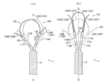
- 5 (a) and 5 (b) are schematic views showing a state in which the electrode unit portion of the electrode catheter shown in FIG. 1 is deformed.
- the solid line shows the posture after deformation
- the broken line shows the initial posture.
- FIG. 5 shows a state in which the electrode catheter 100 is observed from the same direction as in FIG. 4, and typically shows the operation of the two arm members 110A and 110B and the core wire 130A.
- the arm member 110A becomes an arm. Following the member 110B, it moves in the direction of arrow F2 (direction along the circumferential direction) in the figure.
- the core wire 130A functions as a restraining means for restraining the operation of the two arm members 110A and 110B connected by the core wire 130A.
- the core wire 130A functions as a means for prohibiting the arm members 110A and 110B adjacent in the circumferential direction from operating independently.
- the electrode catheter 1 according to the present embodiment is adjacent in the circumferential direction even when the electrode unit 100 is rotated around the axis D of the catheter body 10, for example. It is possible to prevent the arm members 110 from coming into close contact with each other. Therefore, it is possible to prevent unintended concentration of the arm members 110 protruding radially.
- the core wires 130A to 130F have an external force. It is deformed so that the curvature increases according to the magnitude of G. Then, in the electrode unit 100, the arm members 110A to 110F are gathered together on the axis D side, and the arm members 110A to 110F take a focusing posture (collecting posture) in close proximity to each other.
- the electrode unit 100 in a focused posture can move forward and backward in a tubular sheath that guides the electrode unit 100 portion to the heart.
- the electrode unit 100 when an external force (external force from the inside to the outside in the radial direction) is applied to the electrode unit 100 to separate the arm members 110A to 110F from the axis D, the arm members 110A to 110F are further increased from the initial posture. Take a distant posture. At this time, the core wires 130A to 130F are deformed so that the curvature becomes smaller according to the magnitude of the applied external force.
- the length of the intermediate portion 133A of the core wire 130 is set to be longer than the distance between the tips of the arm members 110 and 110 in the initial posture of the electrode unit 100, so that the distance between the tips of the arm members 110 is set. Deformation to separate is allowed.
- the initial posture or the posture in which the arm members 110A to 110F are further separated from the initial posture is the posture when the electrode unit 100 measures the electrocardiographic potential, and the posture in which the electrocardiographic potentials of a large number of locations can be acquired at the same time. That is, it is a posture that enables simultaneous mapping of multiple points.
- the core wire 130 not only functions as a restraining means for restraining the movement of the adjacent arm members 110, but also stores the initial posture of the electrode unit 100 and returns the electrode unit 100 to the initial posture after the electrode unit 100 is deformed. It also functions as a means. By providing the core wire 130 with a plurality of functions, it is possible to reduce the size of the electrode unit 100 as compared with the case where the same function is realized by a plurality of members.
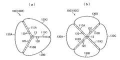
- Modification Embodiment 6 (a) and 6 (b) are schematic views showing an electrode unit portion of an electrode catheter according to a modified embodiment of the present invention. This figure corresponds to the arrow C view of FIG. 1.
- the same reference numerals will be given to the same configurations as those of the first embodiment, and the description thereof will be omitted as appropriate.
- FIG. 6A is a diagram showing an example of an electrode unit 100B including three arm members 110A to 110C and three core wires 130A to 130C.
- FIG. 6B is a diagram showing an example of an electrode unit 100C including four arm members 110A to 110D and four core wires 130A to 130D.
- the number of arm members 110 and the number of core wires 130 included in the electrode unit 100 are free to some extent within the range allowed by the inner diameter of the sheath placed in the blood vessel when the electrode catheter is inserted into the blood vessel. Can be set to.
- This aspect is an electrode catheter 1 including a catheter main body 10 and an electrode unit 100 attached to a tip portion 10a of the catheter main body, and the electrode unit has one end 110a in the longitudinal direction supported by the catheter main body.
- a plurality of arm members 110 having the other end 110b in the longitudinal direction protruding radially from the tip of the catheter body, electrodes attached to each arm member (ring-shaped electrode 120), and adjacent arm members It is characterized by comprising a restraining means (core wire 130) for restraining the operation.
- the restraining means restrains the movement of the adjacent arm members, it is possible to prevent unintended concentration of the vertically protruding arm members.
- each restraining means (core wire 130) connects between the tips of two adjacent arm members 110 and 110 and projects beyond the tips of the respective arm members. It is characterized by. According to this aspect, since the restraining means projects at a position beyond the tip of the arm member, it is possible to prevent the tip of the arm member from piercing the inner wall of the heart and giving unnecessary stimulation to the heart.
- ⁇ Third embodiment> In the electrode catheter 1 according to the present embodiment, at least one restraining means (core wire 130) is inserted into each arm member 110 along the longitudinal direction of each arm member, and the restraining means is the electrode unit 100. It is characterized by memorizing the initial posture.
- the restraining means not only functions as a means for restraining the movement of adjacent arm members, but also functions as a means for storing the initial posture of the electrode unit. By providing the restraining means with a plurality of functions, it is possible to reduce the size of the electrode unit as compared with the case where the same function is realized by a plurality of members.
- the electrode unit 100 is in a focusing posture in which the arm members 110 are close to each other when an external force G from the outer side to the inner side in the radial direction is applied (see the solid line in FIG. 5B).
- each arm member returns to the initial posture (see the broken line in FIG. 5B, FIG. 2, etc.) that spreads radially.
- the electrode unit can be deformed into a focused posture in order to move back and forth in the sheath. Further, when the electrode unit is separated from the sheath, the electrode unit returns to the initial posture, so that it is possible to simultaneously acquire the electrocardiographic potentials of a large number of locations at one time.
- Electrode catheter 10 ... Catheter body, 10a ... Tip, 11 ... Lumen, 13 ... Perfusion port 20 ... Operation unit, 21 ... Handle, 22 ... Rotating plate, 100, 100A-100C ... Electrode unit, 110, 110A- 110F ... arm member, 110a ... one end, 110b ... other end, 111, 111A, 111B ... coated tube, 112, 112A, 112B ... hollow hole, 120 ... ring-shaped electrode, 130, 130A to 130F ... core wire (restraint means) ), 131 ... one end, 132 ... part, 133 ... middle part, 134 ... other part, 135 ... other end.
Landscapes
- Health & Medical Sciences (AREA)
- Life Sciences & Earth Sciences (AREA)
- Medical Informatics (AREA)
- Molecular Biology (AREA)
- Pathology (AREA)
- Engineering & Computer Science (AREA)
- Biomedical Technology (AREA)
- Heart & Thoracic Surgery (AREA)
- Physics & Mathematics (AREA)
- Biophysics (AREA)
- Surgery (AREA)
- Animal Behavior & Ethology (AREA)
- General Health & Medical Sciences (AREA)
- Public Health (AREA)
- Veterinary Medicine (AREA)
- Cardiology (AREA)
- Physiology (AREA)
- Measurement And Recording Of Electrical Phenomena And Electrical Characteristics Of The Living Body (AREA)
Abstract
放射状に突出したアーム部材の意図しない密集を防止する。電極カテーテル(1)は、カテーテル本体(10)と、カテーテル本体の先端部(10a)に取り付けられた電極ユニット(100)とを備える。電極ユニットは、長手方向の一端部(110a)をカテーテル本体によって支持されると共に、長手方向の他端部(110b)がカテーテル本体の先端部から放射状に突出した複数のアーム部材(110)と、各アーム部材に取り付けられたリング状電極(120)と、隣接するアーム部材同士の動作を拘束する拘束手段としてのコアワイヤ(130)と、を備える。
Description
本発明は、心臓内の電気的活性状態のマッピング、及び心臓内壁のアブレーション(焼灼)後の心電位測定に好適な電極カテーテルに関する。
心臓内の電気的活性をマッピングするための電極カテーテルとして、カテーテル本体の先端から放射状に突出した複数のアーム部材を備えたものが知られている(特許文献1)。
この電極カテーテルにおけるアーム部材の夫々には、末端電極およびリング状電極が装着されており、電極カテーテル1本でアーム部材の長手方向長を半径とする円内領域の電位を一度に、且つ同時に測定することができる。
しかし、特許文献1に記載のカテーテルにおいては、アーム部材が何らかの障害物に接触した状態でカテーテル先端部がカテーテル本体の軸線を中心として回転したときに、各アーム部材が密集するという問題がある。その結果、電位の測定が、意図された通りの円内領域で行われることが保証されなくなる。
本発明は上述の事情に鑑みてなされたものであり、放射状に突出したアーム部材の意図しない密集を防止できる電極カテーテルを提供することを目的とする。
上記の課題を解決するために、本発明は、カテーテル本体と、該カテーテル本体の先端部に取り付けられた電極ユニットと、を備えた電極カテーテルであって、前記電極ユニットは、長手方向の一端部を前記カテーテル本体によって支持されると共に、長手方向の他端部が前記カテーテル本体の先端部から放射状に突出した複数のアーム部材と、該各アーム部材に取り付けられた電極と、隣接する前記アーム部材同士の動作を拘束する拘束手段と、を備えることを特徴とする。
本発明によれば、拘束手段が隣接するアーム部材同士の動作を拘束するので、放射状に突出したアーム部材の意図しない密集を防止できる。
以下、本発明を図に示した実施形態を用いて詳細に説明する。但し、この実施形態に記載される構成要素、種類、組み合わせ、形状、その相対配置などは特定的な記載がない限り、この発明の範囲をそれのみに限定する主旨ではなく単なる説明例に過ぎない。
〔第一の実施形態〕
図1は、本発明の一実施形態に係る電極カテーテルの概略構成を示す平面図である。
電極カテーテル1は、血管を通して心臓内に挿入され、心臓内の電気的活性状態のマッピングや心臓内壁のアブレーション(焼灼)後の心電位測定に使用される器具である。
電極カテーテル1は、長手方向に伸びるカテーテル本体10と、カテーテル本体10の基端部10b(近位端側)に取り付けられた操作部20と、カテーテル本体10の先端部10a(遠位端側)に取り付けられた電極ユニット100(100A)とを備える。
図1は、本発明の一実施形態に係る電極カテーテルの概略構成を示す平面図である。
電極カテーテル1は、血管を通して心臓内に挿入され、心臓内の電気的活性状態のマッピングや心臓内壁のアブレーション(焼灼)後の心電位測定に使用される器具である。
電極カテーテル1は、長手方向に伸びるカテーテル本体10と、カテーテル本体10の基端部10b(近位端側)に取り付けられた操作部20と、カテーテル本体10の先端部10a(遠位端側)に取り付けられた電極ユニット100(100A)とを備える。
<カテーテル本体>
カテーテル本体10は、長手方向に伸びる少なくとも1つのルーメン11(図4参照)を備えたチューブ状の部材から構成される。カテーテル本体10のルーメン11内には、電極ユニット100を構成する各リング状電極120,120…と導通する導線(図示省略)や、カテーテル本体10の先端側部位を図1中の矢印B1-B2方向に湾曲変形(又は偏向)させる引っ張りワイヤ(図示省略)等が挿通されている。
カテーテル本体10は、可撓性材料により構成されている。具体的には、カテーテル本体10にはポリオレフィン、ポリアミド、ポリエーテルポリアミド、ポリウレタン、ナイロンおよびPEBAX(登録商標。物質名:ポリエーテルブロックアミド)等の合成樹脂を用いることができる。
カテーテル本体10の外径は1.0~3.5mmであることが好ましく、更に好ましくは1.6~2.8mmとされる。カテーテル本体10の長手方向長は600~1500mmであることが好ましく、更に好ましくは900~1200mmとされる。
なお、カテーテル本体10は、その先端に設けた潅流口13(図3参照)から潅流液を噴射する潅流用のルーメンを備えていてもよい。
なお、カテーテル本体10は、その先端に設けた潅流口13(図3参照)から潅流液を噴射する潅流用のルーメンを備えていてもよい。
<操作部>
操作部20は、電極カテーテル1の操作者が把持するハンドル21と、ハンドル21よりもカテーテル本体10寄りに配置されて、カテーテル本体10の先端側部位を図中矢印B1-B2方向に偏向(或いは湾曲変形)させる回転板22、及び回転板22を回転操作する回転つまみ23と、を備える。
回転板22を図中矢印A1方向に回転させると、カテーテル本体10の先端側部位が回転板22の回転角度に応じた角度で図中矢印B1方向に偏向する。回転板22を図中矢印A2方向に回転させると、カテーテル本体10の先端側部位が回転板22の回転角度に応じた角度で図中矢印B2方向に偏向する。
操作部20は、電極カテーテル1の操作者が把持するハンドル21と、ハンドル21よりもカテーテル本体10寄りに配置されて、カテーテル本体10の先端側部位を図中矢印B1-B2方向に偏向(或いは湾曲変形)させる回転板22、及び回転板22を回転操作する回転つまみ23と、を備える。
回転板22を図中矢印A1方向に回転させると、カテーテル本体10の先端側部位が回転板22の回転角度に応じた角度で図中矢印B1方向に偏向する。回転板22を図中矢印A2方向に回転させると、カテーテル本体10の先端側部位が回転板22の回転角度に応じた角度で図中矢印B2方向に偏向する。
<電極ユニット>
図2は、図1に示した電極カテーテルの先端部分を示す斜視図である。図3は、図1に示した電極カテーテルの電極ユニット部分を図1中矢印C方向から観察した様子を示す図である。
電極ユニット100(100A)は、長手方向の一端部110aをカテーテル本体10の先端部10aによって支持されると共に、長手方向の他端部110bがカテーテル本体10の先端部10aから放射状に突出した複数のアーム部材110(110A~110F)と、各アーム部材110に取り付けられたリング状電極120、120…と、隣接するアーム部材110、110同士の動作を拘束するコアワイヤ(拘束手段)130(130A~130F)と、を備える。
電極ユニット100Aにおいては、6本のアーム部材110A~110Fがカテーテル本体10の長手方向に沿って伸びる軸線D(電極カテーテル1の軸線D)を中心として周方向に並べて配置されている。電極ユニット100Aは、6本のコアワイヤ130A~130Fを備える。1本のコアワイヤ130は、周方向に隣接する2本のアーム部材110,110間、より詳しくは、2本のアーム部材110、110の他端間(先端間)を接続する。即ち、電極ユニット100Aは、アーム部材110と同数のコアワイヤ130を有する。
<<アーム>>
図4は、図1に示した電極カテーテルの先端部分を図3に示したE-E線にて切断した様子を示す縦断面図である。
アーム部材110(110A、110B…)は、長手方向に沿って伸びる中空孔112(112A、112B…)を有した被覆チューブ111(111A、111B…)を備える。被覆チューブ111は、可撓性材料により構成されている。具体的には、被覆チューブ111にはポリオレフィン、ポリアミド、ポリエーテルポリアミド、ポリウレタン、ナイロンおよびPEBAX(登録商標。物質名:ポリエーテルブロックアミド)等の合成樹脂を用いることができる。被覆チューブ111は、カテーテル本体10の先端部10aに、融着等の方法により固定されている。
アーム部材110の外径は0.5~1.0mmであることが好ましく、更に好ましくは0.6~0.8mmとされる。アーム部材110の長手方向長は5~30mmであることが好ましく、更に好ましくは10~20mmとされる。アーム部材110の軸線Dに対する角度は25~90度であることが好ましく、更に好ましくは30~80度とされる。
夫々のアーム部材110は、その外周部に、アーム部材110の長手方向に沿って離間して配置された複数の(ここでは4つの)リング状電極120、120…を備える。リング状電極120、120…は、心臓内の電位を取得する手段であり、例えばプラチナ等の導電性の材料から構成される。被覆チューブ111の中空孔112内には、各リング状電極120、120…と夫々導通する導線(不図示)が挿通されている。なお、各アーム部材110に備えるリング状電極120の数は一例である。各アーム部材110が備えるリング状電極120の数はこれより多くても少なくてもよい。
<<コアワイヤ>>
各アーム部材110を構成する各被覆チューブ111内には、少なくとも1本のコアワイヤ130が、被覆チューブ111の長手方向に沿って挿通されている。本例に示す各アーム部材110には、長手方向の全体に亘って夫々2本のコアワイヤ130、130が挿入されている。
各アーム部材110を構成する各被覆チューブ111内には、少なくとも1本のコアワイヤ130が、被覆チューブ111の長手方向に沿って挿通されている。本例に示す各アーム部材110には、長手方向の全体に亘って夫々2本のコアワイヤ130、130が挿入されている。
例えば、図4に示すように、一本のコアワイヤ130Aは、長手方向の一部132Aを、アーム部材110Aを構成する被覆チューブ111Aによって被覆され、長手方向の他部134Aを、アーム部材110Bを構成する被覆チューブ111Bによって被覆されている。即ち、コアワイヤ130Aは、一部132Aがアーム部材110Aによって保持され、他部134Aがアーム部材110Bによって保持されている。コアワイヤ130Aの一部132Aは他のコアワイヤ130Fの他部134Fに沿って伸びており、長手方向の他部134Aは他のコアワイヤ130Bの一部132Fに沿って伸びている。
コアワイヤ130Aのうち長手方向の一部132Aと他部134Aとの間に位置する中間部133Aは、他のコアワイヤ130B、130Fから独立している。中間部133Aは、アーム部材110A、110Bの先端を越えた位置に突出している。中間部133Aがアーム部材110の先端よりも外側に位置するため、アーム部材110の先端が心臓内壁を突いて心臓に無用な刺激を与えることを防止できる。また、中間部133Aは所定の曲率で凸状に湾曲しているため弾性変形が可能である。従って、中間部133Aが心臓内壁に接触した場合でもそのクッション作用により心臓に無用な刺激を与えることを防止できる。
コアワイヤ130Aの長手方向の各端部(一端部131Aと他端部135A)は、カテーテル本体10の先端部10aの適所に保持されている。従って、電極ユニット100を形成するコアワイヤ130Aの部分(132A~134A)はループ状に構成されている。
各アーム部材110A、110Bの先端開口は、例えばシリコーンゴムやエポキシやポリウレタン等の樹脂材料により封止されている。コアワイヤ130Aは、各アーム部材110A、110Bの先端開口を封止する樹脂材料に固着されている。
他のコアワイヤ130B~130Fの構成は、コアワイヤ130Aの構成と同様である。
各コアワイヤ130は、形状記憶特性と超弾性を有する材料、例えばニチノールワイヤから構成される。コアワイヤ130は、電極ユニット100の初期姿勢(或いは拡開姿勢、図2参照)を記憶している。電極ユニット100は、外力が加えられていない状態において、各アーム部材110A~110Fが放射状に広がった初期姿勢を取る。初期姿勢は、概略花型(Flower Shape)或いは星形(star shape)である。
各コアワイヤ130は、形状記憶特性と超弾性を有する材料、例えばニチノールワイヤから構成される。コアワイヤ130は、電極ユニット100の初期姿勢(或いは拡開姿勢、図2参照)を記憶している。電極ユニット100は、外力が加えられていない状態において、各アーム部材110A~110Fが放射状に広がった初期姿勢を取る。初期姿勢は、概略花型(Flower Shape)或いは星形(star shape)である。
コアワイヤ130の外径は0.07~0.5mmであることが好ましく、更に好ましくは0.1~0.3mmとされる。
アーム部材110の先端から突出するコアワイヤ130の長さは5~30mmであることが好ましく、更に好ましくは10~20mmとされる。
アーム部材110の先端から突出するコアワイヤ130の長さは5~30mmであることが好ましく、更に好ましくは10~20mmとされる。
本例に示すコアワイヤ130Aの中間部133Aは、アーム部材110A、110Bの先端から露出しており、被覆チューブ111A、111Bによって被覆されていない。しかし、コアワイヤ130Aの中間部133Aを被覆チューブ111により被覆した構成としてもよい。中間部133Aを被覆チューブ111により被覆した場合には、当該部位にリング状電極120を取り付けてもよい。他のコアワイヤ130B~130Fについても同様である。
<<動作>>
図5(a)、(b)は、図1に示した電極カテーテルの電極ユニット部分を変形させた様子を示す模式図である。図中、実線は変形後の姿勢を示し、破線は初期姿勢を示す。なお、図5には電極カテーテル100を図4と同様の方向から観察した様子を示しており、代表的に2本のアーム部材110A、110Bとコアワイヤ130Aの動作を示している。
図5(a)、(b)は、図1に示した電極カテーテルの電極ユニット部分を変形させた様子を示す模式図である。図中、実線は変形後の姿勢を示し、破線は初期姿勢を示す。なお、図5には電極カテーテル100を図4と同様の方向から観察した様子を示しており、代表的に2本のアーム部材110A、110Bとコアワイヤ130Aの動作を示している。
図5(a)に示すように、アーム部材110Bに対して、アーム部材110Bをアーム部材110Aから離間させる外力F1(周方向に沿った外力F1)を加えた場合に、アーム部材110Aは、アーム部材110Bに追従して図中矢印F2方向(周方向に沿った方向)へ移動する。このようにコアワイヤ130Aは、コアワイヤ130Aによって接続された2つのアーム部材110A、110Bの動作を拘束する拘束手段として機能する。言い換えれば、コアワイヤ130Aは、周方向に隣接するアーム部材110A、110Bが独立して動作することを禁止する手段として機能する。
本実施形態に係る電極カテーテル1は、拘束手段としてのコアワイヤ130を備えることにより、例えば、カテーテル本体10の軸線Dを中心として電極ユニット100を回転させた場合であっても、周方向に隣接するアーム部材110同士が互いに密着することを阻止できる。従って、放射状に突出したアーム部材110同士の意図しない密集を防止できる。
図5(b)に示すように、電極ユニット100は、電極カテーテル1の軸線Dに向かう外力G(径方向の外側から内側へ向かう外力G)を加えられた場合に、コアワイヤ130A~130Fは外力Gの大きさに応じて曲率が大きくなるように変形する。そして、電極ユニット100は、各アーム部材110A~110Fが軸線D側に寄せ集められて、アーム部材110A~110F同士が近接した集束姿勢(集合姿勢)を取る。集束姿勢を取った電極ユニット100は、電極ユニット100部分を心臓まで案内する筒状のシース内を進退可能である。
逆に、電極ユニット100は、各アーム部材110A~110Fを軸線Dから離反させる外力(径方向の内側から外側へ向かう外力)を加えられた場合に、各アーム部材110A~110Fが初期姿勢から更に離反した姿勢を取る。このとき、コアワイヤ130A~130Fは加えられた外力の大きさに応じて曲率が小さくなるように変形する。電極ユニット100においては、コアワイヤ130の中間部133Aの長さが、電極ユニット100の初期姿勢におけるアーム部材110、110の先端間の距離よりも長く設定されているため、アーム部材110の先端間を離間させる変形が許容される。
電極ユニット100は、図5(a)、(b)に示した外力が取り除かれた場合に、コアワイヤ130が有する形状記憶特性と超弾性によって、破線にて示す初期姿勢に復帰する。初期姿勢又は各アーム部材110A~110Fが初期姿勢から更に離反した姿勢は、電極ユニット100が心電位の測定等をするときの姿勢であり、一度に多数箇所の心電位を同時に取得可能な姿勢、即ち多点同時マッピングが可能な姿勢である。
コアワイヤ130は、隣接するアーム部材110同士の動作を拘束する拘束手段として機能するだけではなく、電極ユニット100の初期姿勢を記憶すると共に、電極ユニット100の変形後に電極ユニット100を初期姿勢に復帰させる手段としても機能する。コアワイヤ130に複数の機能を持たせることにより、同様の機能を複数の部材によって実現する場合に比べて電極ユニット100を小型化することが可能となる。
〔変形実施形態〕
図6(a)、(b)は、本発明の変形実施形態に係る電極カテーテルの電極ユニット部分を示す模式図である。本図は、図1のC矢視図に相当する図である。第一の実施形態と同様の構成については同一の符号を付して適宜その説明を省略する。
図6(a)、(b)は、本発明の変形実施形態に係る電極カテーテルの電極ユニット部分を示す模式図である。本図は、図1のC矢視図に相当する図である。第一の実施形態と同様の構成については同一の符号を付して適宜その説明を省略する。
図6(a)は、3本のアーム部材110A~110C、及び3本のコアワイヤ130A~130Cを備える電極ユニット100Bの例を示す図である。図6(b)は、4本のアーム部材110A~110D、及び4本のコアワイヤ130A~130Dを備える電極ユニット100Cの例を示す図である。
このように、電極ユニット100が備えるアーム部材110の数量、及びコアワイヤ130の数量は、電極カテーテルを血管内に挿入する際に血管内に留置されるシースの内径が許容する範囲内で、ある程度自由に設定できる。
このように、電極ユニット100が備えるアーム部材110の数量、及びコアワイヤ130の数量は、電極カテーテルを血管内に挿入する際に血管内に留置されるシースの内径が許容する範囲内で、ある程度自由に設定できる。
〔本発明の実施態様例と作用、効果のまとめ〕
<第一の実施態様>
本態様は、カテーテル本体10と、カテーテル本体の先端部10aに取り付けられた電極ユニット100と、を備えた電極カテーテル1であって、電極ユニットは、長手方向の一端部110aをカテーテル本体によって支持されると共に、長手方向の他端部110bがカテーテル本体の先端部から放射状に突出した複数のアーム部材110と、各アーム部材に取り付けられた電極(リング状電極120)と、隣接するアーム部材同士の動作を拘束する拘束手段(コアワイヤ130)と、を備えることを特徴とする。
本態様によれば、拘束手段が隣接するアーム部材同士の動作を拘束するので、放射状に突出したアーム部材の意図しない密集を防止できる。
<第二の実施態様>
本実施態様に係る電極カテーテル1において、各拘束手段(コアワイヤ130)は、隣接する2つのアーム部材110、110の先端間を接続すると共に、各アーム部材の先端を越えた位置に突出していることを特徴とする。
本態様によれば、拘束手段がアーム部材の先端を越えた位置に突出しているため、アーム部材の先端が心臓内壁を突いて心臓に無用な刺激を与えることを防止できる。
本実施態様に係る電極カテーテル1において、各拘束手段(コアワイヤ130)は、隣接する2つのアーム部材110、110の先端間を接続すると共に、各アーム部材の先端を越えた位置に突出していることを特徴とする。
本態様によれば、拘束手段がアーム部材の先端を越えた位置に突出しているため、アーム部材の先端が心臓内壁を突いて心臓に無用な刺激を与えることを防止できる。
<第三の実施態様>
本実施態様に係る電極カテーテル1において、各アーム部材110内部には、少なくとも一の拘束手段(コアワイヤ130)が各アーム部材の長手方向に沿って挿通されており、拘束手段は、電極ユニット100の初期姿勢を記憶していることを特徴とする。
本態様において拘束手段は、隣接するアーム部材同士の動作を拘束する手段として機能するだけではなく、電極ユニットの初期姿勢を記憶する手段としても機能する。拘束手段に複数の機能を持たせることにより、同様の機能を複数の部材によって実現する場合に比べて電極ユニットを小型化することが可能となる。
本実施態様に係る電極カテーテル1において、各アーム部材110内部には、少なくとも一の拘束手段(コアワイヤ130)が各アーム部材の長手方向に沿って挿通されており、拘束手段は、電極ユニット100の初期姿勢を記憶していることを特徴とする。
本態様において拘束手段は、隣接するアーム部材同士の動作を拘束する手段として機能するだけではなく、電極ユニットの初期姿勢を記憶する手段としても機能する。拘束手段に複数の機能を持たせることにより、同様の機能を複数の部材によって実現する場合に比べて電極ユニットを小型化することが可能となる。
<第四の実施態様>
本実施態様に係る電極カテーテル1において、電極ユニット100は、径方向外側から内側へ向かう外力Gを加えられた場合に、アーム部材110同士が近接した集束姿勢(図5(b)の実線参照)を取り、外力が取り除かれた場合に各アーム部材が放射状に広がった初期姿勢(図5(b)の破線、図2等参照)に復帰することを特徴とする。
本態様によれば、シース内を進退させるために、電極ユニットを集束姿勢に変形させることができる。また、電極ユニットをシースから離脱させれば電極ユニットが初期姿勢に復帰するので、一度に多数箇所の心電位を同時に取得することが可能となる。
本実施態様に係る電極カテーテル1において、電極ユニット100は、径方向外側から内側へ向かう外力Gを加えられた場合に、アーム部材110同士が近接した集束姿勢(図5(b)の実線参照)を取り、外力が取り除かれた場合に各アーム部材が放射状に広がった初期姿勢(図5(b)の破線、図2等参照)に復帰することを特徴とする。
本態様によれば、シース内を進退させるために、電極ユニットを集束姿勢に変形させることができる。また、電極ユニットをシースから離脱させれば電極ユニットが初期姿勢に復帰するので、一度に多数箇所の心電位を同時に取得することが可能となる。
1…電極カテーテル、10…カテーテル本体、10a…先端部、11…ルーメン、13…潅流口20…操作部、21…ハンドル、22…回転板、100,100A~100C…電極ユニット、110,110A~110F…アーム部材、110a…一端部、110b…他端部、111,111A,111B…被覆チューブ、112,112A,112B…中空孔、120…リング状電極、130,130A~130F…コアワイヤ(拘束手段)、131…一端部、132…一部、133…中間部、134…他部、135…他端部。
Claims (4)
- カテーテル本体と、該カテーテル本体の先端部に取り付けられた電極ユニットと、を備えた電極カテーテルであって、
前記電極ユニットは、長手方向の一端部を前記カテーテル本体によって支持されると共に、長手方向の他端部が前記カテーテル本体の先端部から放射状に突出した複数のアーム部材と、該各アーム部材に取り付けられた電極と、隣接する前記アーム部材同士の動作を拘束する拘束手段と、を備えることを特徴とする電極カテーテル。 - 各前記拘束手段は、隣接する2つの前記アーム部材の先端間を接続すると共に、前記各アーム部材の先端を越えた位置に突出していることを特徴とする請求項1に記載の電極カテーテル。
- 前記各アーム部材内部には、少なくとも一の前記拘束手段が前記各アーム部材の長手方向に沿って挿通されており、該拘束手段は、前記電極ユニットの初期姿勢を記憶していることを特徴とする請求項2に記載の電極カテーテル。
- 前記電極ユニットは、径方向外側から内側へ向かう外力を加えられた場合に、前記アーム部材同士が近接した集束姿勢を取り、前記外力が取り除かれた場合に前記各アーム部材が放射状に広がった初期姿勢に復帰することを特徴とする請求項3に記載の電極カテーテル。
Priority Applications (4)
| Application Number | Priority Date | Filing Date | Title |
|---|---|---|---|
| PCT/JP2019/012885 WO2020194511A1 (ja) | 2019-03-26 | 2019-03-26 | 電極カテーテル |
| JP2021508474A JP7135202B2 (ja) | 2019-03-26 | 2019-03-26 | 電極カテーテル |
| US17/310,795 US12133735B2 (en) | 2019-03-26 | 2019-03-26 | Electrode catheter |
| EP19921803.3A EP3949848A4 (en) | 2019-03-26 | 2019-03-26 | ELECTRODE CATHETER |
Applications Claiming Priority (1)
| Application Number | Priority Date | Filing Date | Title |
|---|---|---|---|
| PCT/JP2019/012885 WO2020194511A1 (ja) | 2019-03-26 | 2019-03-26 | 電極カテーテル |
Publications (1)
| Publication Number | Publication Date |
|---|---|
| WO2020194511A1 true WO2020194511A1 (ja) | 2020-10-01 |
Family
ID=72611691
Family Applications (1)
| Application Number | Title | Priority Date | Filing Date |
|---|---|---|---|
| PCT/JP2019/012885 Ceased WO2020194511A1 (ja) | 2019-03-26 | 2019-03-26 | 電極カテーテル |
Country Status (4)
| Country | Link |
|---|---|
| US (1) | US12133735B2 (ja) |
| EP (1) | EP3949848A4 (ja) |
| JP (1) | JP7135202B2 (ja) |
| WO (1) | WO2020194511A1 (ja) |
Families Citing this family (2)
| Publication number | Priority date | Publication date | Assignee | Title |
|---|---|---|---|---|
| JP7515637B2 (ja) | 2020-08-18 | 2024-07-12 | セント・ジュード・メディカル,カーディオロジー・ディヴィジョン,インコーポレイテッド | 磁気位置の追跡を伴う高密度電極カテーテル |
| US12551658B2 (en) | 2022-03-25 | 2026-02-17 | St. Jude Medical, Cardiology Division, Inc. | Steerable introducer with slide block divider |
Citations (3)
| Publication number | Priority date | Publication date | Assignee | Title |
|---|---|---|---|---|
| JP2003235821A (ja) | 2001-12-31 | 2003-08-26 | Biosense Webster Inc | 電気的マッピング能力および位置感知能力をそれぞれ有している多数のとげ状突起を有するカテーテル |
| JP2017104552A (ja) * | 2015-12-10 | 2017-06-15 | バイオセンス・ウエブスター・(イスラエル)・リミテッドBiosense Webster (Israel), Ltd. | 安定化スパイン電気生理学カテーテル |
| JP2018108376A (ja) * | 2017-01-05 | 2018-07-12 | バイオセンス・ウエブスター・(イスラエル)・リミテッドBiosense Webster (Israel), Ltd. | ハイブリッドバルーンバスケットカテーテル |
Family Cites Families (8)
| Publication number | Priority date | Publication date | Assignee | Title |
|---|---|---|---|---|
| EP3113679B1 (en) * | 2014-05-06 | 2019-09-25 | St. Jude Medical, Cardiology Division, Inc. | Electrode support structure assembly |
| US10130420B2 (en) | 2015-10-08 | 2018-11-20 | Biosense Webster (Israel) Ltd. | Catheter with membraned spines for pulmonary vein isolation |
| EP4230133B1 (en) * | 2015-10-21 | 2025-09-17 | Autonomix Medical, Inc. | Controlled and precise treatment of cardiac tissues |
| US10362953B2 (en) * | 2015-12-11 | 2019-07-30 | Biosense Webster (Israel) Ltd. | Electrode array catheter with interconnected framework |
| US9907480B2 (en) | 2016-02-08 | 2018-03-06 | Biosense Webster (Israel) Ltd. | Catheter spine assembly with closely-spaced bipole microelectrodes |
| US10362991B2 (en) * | 2016-04-04 | 2019-07-30 | Biosense Webster (Israel) Ltd. | Convertible basket catheter |
| US11540876B2 (en) * | 2016-05-03 | 2023-01-03 | St. Jude Medical Cardiology Division, Inc. | Irrigated high density electrode catheter |
| US20190183372A1 (en) * | 2016-09-07 | 2019-06-20 | Ablacon Inc. | Multiple Configuration Electrophysiological Mapping Catheter, and Systems, Devices, Components and Methods Associated Therewith |
-
2019
- 2019-03-26 US US17/310,795 patent/US12133735B2/en active Active
- 2019-03-26 JP JP2021508474A patent/JP7135202B2/ja active Active
- 2019-03-26 EP EP19921803.3A patent/EP3949848A4/en not_active Withdrawn
- 2019-03-26 WO PCT/JP2019/012885 patent/WO2020194511A1/ja not_active Ceased
Patent Citations (3)
| Publication number | Priority date | Publication date | Assignee | Title |
|---|---|---|---|---|
| JP2003235821A (ja) | 2001-12-31 | 2003-08-26 | Biosense Webster Inc | 電気的マッピング能力および位置感知能力をそれぞれ有している多数のとげ状突起を有するカテーテル |
| JP2017104552A (ja) * | 2015-12-10 | 2017-06-15 | バイオセンス・ウエブスター・(イスラエル)・リミテッドBiosense Webster (Israel), Ltd. | 安定化スパイン電気生理学カテーテル |
| JP2018108376A (ja) * | 2017-01-05 | 2018-07-12 | バイオセンス・ウエブスター・(イスラエル)・リミテッドBiosense Webster (Israel), Ltd. | ハイブリッドバルーンバスケットカテーテル |
Non-Patent Citations (1)
| Title |
|---|
| See also references of EP3949848A4 |
Also Published As
| Publication number | Publication date |
|---|---|
| JP7135202B2 (ja) | 2022-09-12 |
| JPWO2020194511A1 (ja) | 2021-11-25 |
| EP3949848A4 (en) | 2022-09-21 |
| EP3949848A1 (en) | 2022-02-09 |
| US12133735B2 (en) | 2024-11-05 |
| US20220133203A1 (en) | 2022-05-05 |
Similar Documents
| Publication | Publication Date | Title |
|---|---|---|
| US20250318784A1 (en) | Basket for a Multi-Electrode Array Catheter | |
| US20230346471A1 (en) | Medical probe with wiring disposed between two expandable membranes | |
| JP6771878B2 (ja) | 微小電極アレイ遠位先端部を有するバスケットカテーテル | |
| CN106264716B (zh) | 具有堆叠脊电极组件的导管 | |
| US9149198B2 (en) | Multi-array monophasic potential medical device | |
| JP2021512772A (ja) | 電極が互い違いの配置を有するスパインアセンブリを有するカテーテル | |
| CN106308790A (zh) | 具有带一致长度脊的闭合电极组件的导管 | |
| JP2021512759A (ja) | 組織との接触を改善するために予め成形された形状部を有する電極スパインアセンブリを有するカテーテル | |
| JP2016083372A5 (ja) | ||
| JP2021512770A (ja) | 強化されたスパインカバーを有する、電極密度の高いスパインアセンブリを有するカテーテル | |
| JP2021512771A (ja) | 互い違い状の微小電極配置を有する医療プローブ | |
| WO2020194511A1 (ja) | 電極カテーテル | |
| JP5339630B2 (ja) | 電極カテーテル | |
| WO2013145891A1 (ja) | 電極カテーテル | |
| JP6529770B2 (ja) | 電極カテーテル、電極カテーテルの製造方法 | |
| JP4925206B2 (ja) | 電極カテーテル | |
| JP4925210B2 (ja) | 電極カテーテル | |
| WO2012046499A1 (ja) | 電極カテーテル | |
| CN112294433A (zh) | 标测导丝及应用其的三维标测系统 | |
| WO2018131201A1 (ja) | コネクタ及び医療機器 | |
| JP2023169523A (ja) | プラズマガイドワイヤ | |
| JP2024124205A (ja) | 電極カテーテル | |
| JP2011147682A (ja) | 電極カテーテル |
Legal Events
| Date | Code | Title | Description |
|---|---|---|---|
| 121 | Ep: the epo has been informed by wipo that ep was designated in this application |
Ref document number: 19921803 Country of ref document: EP Kind code of ref document: A1 |
|
| ENP | Entry into the national phase |
Ref document number: 2021508474 Country of ref document: JP Kind code of ref document: A |
|
| NENP | Non-entry into the national phase |
Ref country code: DE |
|
| ENP | Entry into the national phase |
Ref document number: 2019921803 Country of ref document: EP Effective date: 20211026 |