WO2020194783A1 - 電源装置と電源装置を備える電動車両及び蓄電装置 - Google Patents
電源装置と電源装置を備える電動車両及び蓄電装置 Download PDFInfo
- Publication number
- WO2020194783A1 WO2020194783A1 PCT/JP2019/033263 JP2019033263W WO2020194783A1 WO 2020194783 A1 WO2020194783 A1 WO 2020194783A1 JP 2019033263 W JP2019033263 W JP 2019033263W WO 2020194783 A1 WO2020194783 A1 WO 2020194783A1
- Authority
- WO
- WIPO (PCT)
- Prior art keywords
- power supply
- supply device
- arm portion
- rod
- rod portion
- Prior art date
- Legal status (The legal status is an assumption and is not a legal conclusion. Google has not performed a legal analysis and makes no representation as to the accuracy of the status listed.)
- Ceased
Links
Images


Classifications
-
- H—ELECTRICITY
- H01—ELECTRIC ELEMENTS
- H01M—PROCESSES OR MEANS, e.g. BATTERIES, FOR THE DIRECT CONVERSION OF CHEMICAL ENERGY INTO ELECTRICAL ENERGY
- H01M50/00—Constructional details or processes of manufacture of the non-active parts of electrochemical cells other than fuel cells, e.g. hybrid cells
- H01M50/50—Current conducting connections for cells or batteries
- H01M50/502—Interconnectors for connecting terminals of adjacent batteries; Interconnectors for connecting cells outside a battery casing
- H01M50/505—Interconnectors for connecting terminals of adjacent batteries; Interconnectors for connecting cells outside a battery casing comprising a single busbar
-
- B—PERFORMING OPERATIONS; TRANSPORTING
- B60—VEHICLES IN GENERAL
- B60L—PROPULSION OF ELECTRICALLY-PROPELLED VEHICLES; SUPPLYING ELECTRIC POWER FOR AUXILIARY EQUIPMENT OF ELECTRICALLY-PROPELLED VEHICLES; ELECTRODYNAMIC BRAKE SYSTEMS FOR VEHICLES IN GENERAL; MAGNETIC SUSPENSION OR LEVITATION FOR VEHICLES; MONITORING OPERATING VARIABLES OF ELECTRICALLY-PROPELLED VEHICLES; ELECTRIC SAFETY DEVICES FOR ELECTRICALLY-PROPELLED VEHICLES
- B60L50/00—Electric propulsion with power supplied within the vehicle
- B60L50/50—Electric propulsion with power supplied within the vehicle using propulsion power supplied by batteries or fuel cells
- B60L50/51—Electric propulsion with power supplied within the vehicle using propulsion power supplied by batteries or fuel cells characterised by AC-motors
-
- B—PERFORMING OPERATIONS; TRANSPORTING
- B60—VEHICLES IN GENERAL
- B60L—PROPULSION OF ELECTRICALLY-PROPELLED VEHICLES; SUPPLYING ELECTRIC POWER FOR AUXILIARY EQUIPMENT OF ELECTRICALLY-PROPELLED VEHICLES; ELECTRODYNAMIC BRAKE SYSTEMS FOR VEHICLES IN GENERAL; MAGNETIC SUSPENSION OR LEVITATION FOR VEHICLES; MONITORING OPERATING VARIABLES OF ELECTRICALLY-PROPELLED VEHICLES; ELECTRIC SAFETY DEVICES FOR ELECTRICALLY-PROPELLED VEHICLES
- B60L50/00—Electric propulsion with power supplied within the vehicle
- B60L50/50—Electric propulsion with power supplied within the vehicle using propulsion power supplied by batteries or fuel cells
- B60L50/60—Electric propulsion with power supplied within the vehicle using propulsion power supplied by batteries or fuel cells using power supplied by batteries
-
- H—ELECTRICITY
- H01—ELECTRIC ELEMENTS
- H01M—PROCESSES OR MEANS, e.g. BATTERIES, FOR THE DIRECT CONVERSION OF CHEMICAL ENERGY INTO ELECTRICAL ENERGY
- H01M10/00—Secondary cells; Manufacture thereof
- H01M10/05—Accumulators with non-aqueous electrolyte
- H01M10/052—Li-accumulators
- H01M10/0525—Rocking-chair batteries, i.e. batteries with lithium insertion or intercalation in both electrodes; Lithium-ion batteries
-
- H—ELECTRICITY
- H01—ELECTRIC ELEMENTS
- H01M—PROCESSES OR MEANS, e.g. BATTERIES, FOR THE DIRECT CONVERSION OF CHEMICAL ENERGY INTO ELECTRICAL ENERGY
- H01M10/00—Secondary cells; Manufacture thereof
- H01M10/42—Methods or arrangements for servicing or maintenance of secondary cells or secondary half-cells
- H01M10/4207—Methods or arrangements for servicing or maintenance of secondary cells or secondary half-cells for several batteries or cells simultaneously or sequentially
-
- H—ELECTRICITY
- H01—ELECTRIC ELEMENTS
- H01M—PROCESSES OR MEANS, e.g. BATTERIES, FOR THE DIRECT CONVERSION OF CHEMICAL ENERGY INTO ELECTRICAL ENERGY
- H01M10/00—Secondary cells; Manufacture thereof
- H01M10/42—Methods or arrangements for servicing or maintenance of secondary cells or secondary half-cells
- H01M10/425—Structural combination with electronic components, e.g. electronic circuits integrated to the outside of the casing
-
- H—ELECTRICITY
- H01—ELECTRIC ELEMENTS
- H01M—PROCESSES OR MEANS, e.g. BATTERIES, FOR THE DIRECT CONVERSION OF CHEMICAL ENERGY INTO ELECTRICAL ENERGY
- H01M10/00—Secondary cells; Manufacture thereof
- H01M10/42—Methods or arrangements for servicing or maintenance of secondary cells or secondary half-cells
- H01M10/44—Methods for charging or discharging
-
- H—ELECTRICITY
- H01—ELECTRIC ELEMENTS
- H01M—PROCESSES OR MEANS, e.g. BATTERIES, FOR THE DIRECT CONVERSION OF CHEMICAL ENERGY INTO ELECTRICAL ENERGY
- H01M50/00—Constructional details or processes of manufacture of the non-active parts of electrochemical cells other than fuel cells, e.g. hybrid cells
- H01M50/20—Mountings; Secondary casings or frames; Racks, modules or packs; Suspension devices; Shock absorbers; Transport or carrying devices; Holders
- H01M50/249—Mountings; Secondary casings or frames; Racks, modules or packs; Suspension devices; Shock absorbers; Transport or carrying devices; Holders specially adapted for aircraft or vehicles, e.g. cars or trains
-
- H—ELECTRICITY
- H01—ELECTRIC ELEMENTS
- H01M—PROCESSES OR MEANS, e.g. BATTERIES, FOR THE DIRECT CONVERSION OF CHEMICAL ENERGY INTO ELECTRICAL ENERGY
- H01M50/00—Constructional details or processes of manufacture of the non-active parts of electrochemical cells other than fuel cells, e.g. hybrid cells
- H01M50/20—Mountings; Secondary casings or frames; Racks, modules or packs; Suspension devices; Shock absorbers; Transport or carrying devices; Holders
- H01M50/262—Mountings; Secondary casings or frames; Racks, modules or packs; Suspension devices; Shock absorbers; Transport or carrying devices; Holders with fastening means, e.g. locks
- H01M50/264—Mountings; Secondary casings or frames; Racks, modules or packs; Suspension devices; Shock absorbers; Transport or carrying devices; Holders with fastening means, e.g. locks for cells or batteries, e.g. straps, tie rods or peripheral frames
-
- H—ELECTRICITY
- H01—ELECTRIC ELEMENTS
- H01M—PROCESSES OR MEANS, e.g. BATTERIES, FOR THE DIRECT CONVERSION OF CHEMICAL ENERGY INTO ELECTRICAL ENERGY
- H01M50/00—Constructional details or processes of manufacture of the non-active parts of electrochemical cells other than fuel cells, e.g. hybrid cells
- H01M50/50—Current conducting connections for cells or batteries
- H01M50/502—Interconnectors for connecting terminals of adjacent batteries; Interconnectors for connecting cells outside a battery casing
- H01M50/503—Interconnectors for connecting terminals of adjacent batteries; Interconnectors for connecting cells outside a battery casing characterised by the shape of the interconnectors
-
- H—ELECTRICITY
- H01—ELECTRIC ELEMENTS
- H01M—PROCESSES OR MEANS, e.g. BATTERIES, FOR THE DIRECT CONVERSION OF CHEMICAL ENERGY INTO ELECTRICAL ENERGY
- H01M50/00—Constructional details or processes of manufacture of the non-active parts of electrochemical cells other than fuel cells, e.g. hybrid cells
- H01M50/50—Current conducting connections for cells or batteries
- H01M50/502—Interconnectors for connecting terminals of adjacent batteries; Interconnectors for connecting cells outside a battery casing
- H01M50/514—Methods for interconnecting adjacent batteries or cells
- H01M50/516—Methods for interconnecting adjacent batteries or cells by welding, soldering or brazing
-
- H—ELECTRICITY
- H02—GENERATION; CONVERSION OR DISTRIBUTION OF ELECTRIC POWER
- H02J—ELECTRIC POWER NETWORKS; CIRCUIT ARRANGEMENTS OR SYSTEMS FOR SUPPLYING OR DISTRIBUTING ELECTRIC POWER; SYSTEMS FOR STORING ELECTRIC ENERGY
- H02J7/00—Circuit arrangements for charging or discharging batteries or for supplying loads from batteries
- H02J7/50—Circuit arrangements for charging or discharging batteries or for supplying loads from batteries acting upon multiple batteries simultaneously or sequentially
-
- H—ELECTRICITY
- H02—GENERATION; CONVERSION OR DISTRIBUTION OF ELECTRIC POWER
- H02J—ELECTRIC POWER NETWORKS; CIRCUIT ARRANGEMENTS OR SYSTEMS FOR SUPPLYING OR DISTRIBUTING ELECTRIC POWER; SYSTEMS FOR STORING ELECTRIC ENERGY
- H02J7/00—Circuit arrangements for charging or discharging batteries or for supplying loads from batteries
- H02J7/70—Circuit arrangements for charging or discharging batteries or for supplying loads from batteries characterised by the mechanical construction
-
- H—ELECTRICITY
- H02—GENERATION; CONVERSION OR DISTRIBUTION OF ELECTRIC POWER
- H02J—ELECTRIC POWER NETWORKS; CIRCUIT ARRANGEMENTS OR SYSTEMS FOR SUPPLYING OR DISTRIBUTING ELECTRIC POWER; SYSTEMS FOR STORING ELECTRIC ENERGY
- H02J7/00—Circuit arrangements for charging or discharging batteries or for supplying loads from batteries
- H02J7/855—Circuit arrangements for charging or discharging batteries or for supplying loads from batteries with circuits adapted for supplying loads from the battery
-
- B—PERFORMING OPERATIONS; TRANSPORTING
- B60—VEHICLES IN GENERAL
- B60L—PROPULSION OF ELECTRICALLY-PROPELLED VEHICLES; SUPPLYING ELECTRIC POWER FOR AUXILIARY EQUIPMENT OF ELECTRICALLY-PROPELLED VEHICLES; ELECTRODYNAMIC BRAKE SYSTEMS FOR VEHICLES IN GENERAL; MAGNETIC SUSPENSION OR LEVITATION FOR VEHICLES; MONITORING OPERATING VARIABLES OF ELECTRICALLY-PROPELLED VEHICLES; ELECTRIC SAFETY DEVICES FOR ELECTRICALLY-PROPELLED VEHICLES
- B60L2210/00—Converter types
- B60L2210/40—DC to AC converters
-
- H—ELECTRICITY
- H01—ELECTRIC ELEMENTS
- H01M—PROCESSES OR MEANS, e.g. BATTERIES, FOR THE DIRECT CONVERSION OF CHEMICAL ENERGY INTO ELECTRICAL ENERGY
- H01M2220/00—Batteries for particular applications
- H01M2220/20—Batteries in motive systems, e.g. vehicle, ship, plane
-
- H—ELECTRICITY
- H01—ELECTRIC ELEMENTS
- H01M—PROCESSES OR MEANS, e.g. BATTERIES, FOR THE DIRECT CONVERSION OF CHEMICAL ENERGY INTO ELECTRICAL ENERGY
- H01M50/00—Constructional details or processes of manufacture of the non-active parts of electrochemical cells other than fuel cells, e.g. hybrid cells
- H01M50/20—Mountings; Secondary casings or frames; Racks, modules or packs; Suspension devices; Shock absorbers; Transport or carrying devices; Holders
- H01M50/204—Racks, modules or packs for multiple batteries or multiple cells
- H01M50/207—Racks, modules or packs for multiple batteries or multiple cells characterised by their shape
- H01M50/209—Racks, modules or packs for multiple batteries or multiple cells characterised by their shape adapted for prismatic or rectangular cells
-
- H—ELECTRICITY
- H01—ELECTRIC ELEMENTS
- H01M—PROCESSES OR MEANS, e.g. BATTERIES, FOR THE DIRECT CONVERSION OF CHEMICAL ENERGY INTO ELECTRICAL ENERGY
- H01M50/00—Constructional details or processes of manufacture of the non-active parts of electrochemical cells other than fuel cells, e.g. hybrid cells
- H01M50/20—Mountings; Secondary casings or frames; Racks, modules or packs; Suspension devices; Shock absorbers; Transport or carrying devices; Holders
- H01M50/289—Mountings; Secondary casings or frames; Racks, modules or packs; Suspension devices; Shock absorbers; Transport or carrying devices; Holders characterised by spacing elements or positioning means within frames, racks or packs
- H01M50/293—Mountings; Secondary casings or frames; Racks, modules or packs; Suspension devices; Shock absorbers; Transport or carrying devices; Holders characterised by spacing elements or positioning means within frames, racks or packs characterised by the material
-
- Y—GENERAL TAGGING OF NEW TECHNOLOGICAL DEVELOPMENTS; GENERAL TAGGING OF CROSS-SECTIONAL TECHNOLOGIES SPANNING OVER SEVERAL SECTIONS OF THE IPC; TECHNICAL SUBJECTS COVERED BY FORMER USPC CROSS-REFERENCE ART COLLECTIONS [XRACs] AND DIGESTS
- Y02—TECHNOLOGIES OR APPLICATIONS FOR MITIGATION OR ADAPTATION AGAINST CLIMATE CHANGE
- Y02E—REDUCTION OF GREENHOUSE GAS [GHG] EMISSIONS, RELATED TO ENERGY GENERATION, TRANSMISSION OR DISTRIBUTION
- Y02E60/00—Enabling technologies; Technologies with a potential or indirect contribution to GHG emissions mitigation
- Y02E60/10—Energy storage using batteries
-
- Y—GENERAL TAGGING OF NEW TECHNOLOGICAL DEVELOPMENTS; GENERAL TAGGING OF CROSS-SECTIONAL TECHNOLOGIES SPANNING OVER SEVERAL SECTIONS OF THE IPC; TECHNICAL SUBJECTS COVERED BY FORMER USPC CROSS-REFERENCE ART COLLECTIONS [XRACs] AND DIGESTS
- Y02—TECHNOLOGIES OR APPLICATIONS FOR MITIGATION OR ADAPTATION AGAINST CLIMATE CHANGE
- Y02T—CLIMATE CHANGE MITIGATION TECHNOLOGIES RELATED TO TRANSPORTATION
- Y02T10/00—Road transport of goods or passengers
- Y02T10/60—Other road transportation technologies with climate change mitigation effect
- Y02T10/70—Energy storage systems for electromobility, e.g. batteries
Definitions
- the present invention relates to a power supply device in which a plurality of battery cells are electrically connected by a bus bar, and an electric vehicle and a power storage device provided with this power supply device.
- the power supply can increase the output and capacity by increasing the number of battery cells to be connected. For this reason, power supplies used for applications that require high output, such as power supplies for electric vehicles such as hybrid cars and electric vehicles, and uninterruptible power supplies for servers, connect a large number of battery cells in series or in parallel. The output and capacity are increased.
- a large number of battery cells are stacked to form a battery block, and adjacent battery cells are electrically connected by a metal plate bus bar.
- a power supply device including a plurality of battery cells is described in the following patent documents. (See Patent Document 1)
- a plurality of battery cells are electrically connected by a bus bar.
- the battery cell can be connected with a small electric resistance by laminating a metal plate bus bar on the electrode terminal of the battery cell and welding the laminated portion to the electrode terminal.
- the relative misalignment between the bus bar and the electrode terminals causes the reliable welding to be hindered.
- a power supply device in which a large number of battery cells are assembled into a battery block and a bus bar is welded to each battery cell constituting the battery block, it is difficult to arrange the electrode terminals of all the battery cells at accurate positions.
- the battery cell has a dimensional error in the assembly process, and this dimensional error causes a relative misalignment between the electrode terminal and the bus bar.
- this dimensional error causes a relative misalignment between the electrode terminal and the bus bar.
- a thick metal plate with low electrical resistance is used for the bus bar, it is necessary to suppress heat generation due to a large current requirement and increase the cross-sectional area so as not to melt, and it is necessary to increase the thickness of the bus bar. This makes it difficult to reliably weld the bus bar and the electrode terminals due to the relative misalignment.
- the present invention is to provide an electric vehicle and a power storage device provided with a power supply device and a power supply device capable of reliably welding the bus bar and the electrode terminals in close contact with each other while preventing the above adverse effects.
- the power supply device of an aspect of the present invention is a power supply device in which a plurality of battery cells 1 are electrically connected by a bus bar 3, and the bus bar 3 includes a conductive rod portion 4 extending in the arrangement direction of the battery cells 1 and a conductive rod portion 4.
- the arm portion 5 is provided with an elastically deformable arm portion 5 connected to the rod portion 4, and the tip portion 5x of the arm portion 5x is welded to the electrode terminal 2 of the battery cell 1 to connect the rear end portion 5y to the rod portion 4.
- a plurality of battery cells 1 are electrically connected via the rod portion 4, and the arm portion 5 is a conductive plate that can be elastically deformed, and is between the rod portion 4 and the rear end portion 5y.
- a deformation gap 6 is provided on the tip side, and the arm portion 5 is elastically deformed so that the tip portion 5x welded to the electrode terminal 2 can be displaced.
- an electric vehicle including a power supply device having the above-described components includes a power supply device 100, a traveling motor 93 to which power is supplied from the power supply device 100, a power supply device 100, and a motor 93. It includes a vehicle body 91 and wheels 97 that are driven by a motor 93 to drive the vehicle body 91.
- the power storage device including the power supply device having the above-described components includes a power supply device 100 and a power supply controller 88 that controls charging / discharging to the power supply device 100, and the power supply controller 88 is a battery powered by external power.
- the cell 1 can be charged, and the battery cell 1 is controlled to be charged.
- the bus bar and the electrode terminals are in close contact with each other without any gaps, and there is a feature that they can be reliably welded.
- FIG. It is a schematic perspective view of the power supply device which concerns on one Embodiment of this invention. It is an exploded perspective view of the power supply device shown in FIG. It is an enlarged perspective view of the power supply device shown in FIG. It is a vertical cross-sectional view which shows the connection structure of a bus bar and an electrode terminal. It is a perspective view of the bus bar shown in FIG. It is a rear perspective view of the bus bar shown in FIG. It is a perspective view which shows another example of a bus bar. It is a perspective view which shows another example of a bus bar. It is a perspective view which shows another example of a bus bar. It is a perspective view which shows another example of a bus bar. It is a perspective view which shows another example of a bus bar. It is a perspective view which shows another example of a bus bar. It is a perspective view which shows another example of a bus bar. It is a perspective view which shows another example of a bus bar. It is a perspective view which shows another example of a bus
- the bus bar whose arm is fixed to the rod has a feature that the electric resistance of the bus bar can be reduced by the rod, but the cross-sectional area can be increased by the rod where current flows from a plurality of arms and a large current flows.
- it has a feature, it is less likely to be elastically deformed as compared with a bus bar having a single metal plate as a whole, and there is a problem of poor connection due to misalignment between the bus bar and the electrode terminals. Further, in the state after welding, there is a problem that the welded portion is more likely to come off due to impact and vibration as compared with one metal plate.
- the present inventors have found that while using a low-resistance bus bar in which the arm portion is connected to the rod portion, the gap between the bus bar and the electrode terminal can be reduced to ensure welding. , The present invention has been reached.
- the power supply device is a power supply device in which a plurality of battery cells are electrically connected by a bus bar, and the bus bar has a conductive rod portion extending in the arrangement direction of the battery cells and a rod portion.
- the arm portion is provided with an elastically deformable arm portion connected to the above, and the tip portion of the arm portion is welded to the electrode terminal of the battery cell and the rear end portion is connected to the rod portion, and a plurality of arm portions are connected via the rod portion.
- the battery cell is electrically connected, and the arm portion is a conductive plate that can be elastically deformed.
- a deformation gap is provided between the rod portion and the rear end portion to the tip portion, and the arm portion is elastic. The structure is such that the tip portion that is deformed and welded to the electrode terminal can be displaced.
- the bus bar of the above power supply device has a structure in which a plurality of elastically deformable arm portions are connected to the rod portion, and the arm portion connects the rear end portion to the rod portion and welds the tip portion to the electrode terminal, and further, the arm A deformation gap is provided between the portion and the rod portion on the tip side of the rear end portion of the arm portion to lengthen the region where the arm portion elastically deforms, so that the arm portion can be easily elastically deformed.
- the tip can be moved to the ideal position of the electrode terminal.
- the arm part that elastically deforms smoothly and can move the tip part to the ideal position without difficulty moves to the ideal position with respect to the electrode terminal that is misaligned due to an error in the manufacturing process, etc.
- the elastic deformation region of the arm portion is lengthened while reducing the amount of protrusion of the arm portion from the rod portion, and the tip portion is formed.
- the part can be approached to the electrode terminal without difficulty.
- the long arm part can be elastically deformed so that the tip part can approach the electrode terminal, the change in posture when the tip part is close to the electrode terminal is small, and the ideal posture with respect to the electrode terminal is ideal. After moving to a specific position and attaching the tip to the electrode terminal, it is elastically deformed by applying a load to the upper surface of the bus bar, so that gaps can be easily eliminated and welding can be performed reliably.
- the tip end portion of the arm portion is laminated on the electrode terminal and welded.
- the power supply device is provided with a deformation gap between it and the rod portion so as to allow vertical displacement of the tip portion of the arm portion.
- the power supply device is provided with a deformation gap between it and the rod portion so as to allow horizontal displacement of the tip portion of the arm portion.
- the rear end portion of the arm portion is connected to the side surface of the rod portion on the side opposite to the electrode terminal, and a deformation gap is formed between the arm portion and the rod portion. It is provided.
- the rod portion has a polygonal columnar shape or a columnar shape.
- the rod portion is a columnar shape having a vertical surface
- the arm portion connects the rear end portion to the vertical surface of the rod portion and is deformed between the rod portion and the vertical surface of the rod portion. There is a gap.
- the power supply device has a prismatic shape in which the rod portion has a vertical plane and a horizontal plane, the arm portion has a shape along the horizontal plane to the vertical plane of the rod portion, and the arm portion is on the vertical plane of the rod portion.
- the rear end portion is connected to provide a deformation gap between the rod portion and the horizontal portion.
- the rod portion is a columnar metal rod, and the rear end portion of the arm portion is welded and fixed to the rod portion.
- the rod portion is wound around a metal plate and laminated in a spiral shape, and the arm portion is integrally connected to the metal plate.
- the power supply device includes a tubular portion in which a rod portion is formed by bending a metal plate into a tubular shape, and a columnar portion inserted inside the tubular portion.
- the arm portion is integrally connected to the metal plate.
- the power supply device includes a quadrangular region having a quadrangular outer shape and a plurality of protrusions from one side edge of the quadrangular region, which constitute a rod portion in a deployed state of the metal plate. It is cut into a shape having an arm portion.
- the power supply device is a square battery in which a battery cell closes an opening of an outer can with a sealing plate, and a plurality of battery cells are laminated to form a battery block. Is provided with positive and negative electrode terminals, and a pair of rod portions are arranged outside the positive and negative electrode terminals, and the pair of rod portions are the upper surface of the sealing plate and are arranged so as to extend in the arrangement direction of the battery cells. , The arm portion extends from the rod portion to the electrode terminal, and the tip portion is welded to the electrode terminal.
- the arm portion is arranged on the side surface side of the rod portion, and the rear end portion is connected to the rod portion, and the arm portion is connected to the upper end of the connecting arm portion.
- a horizontal arm portion that extends beyond the upper surface of the rod portion toward the tip side, a plate-shaped vertical arm portion that is connected to the side edge of the horizontal arm portion, and a horizontal arm portion that is connected to the vertical arm portion in a horizontal posture. It is provided with a welded portion, and the welded portion is welded to the electrode terminal in a laminated state.
- the arm portion is arranged on the side surface side of the rod portion, and the rear end portion is connected to the rod portion, and the arm portion is connected to the upper end of the connecting arm portion.
- a horizontal arm portion that extends beyond the upper surface of the rod portion toward the tip side, a plate-shaped vertical arm portion that is connected to the tip edge of the horizontal arm portion, and a horizontal arm portion that is connected to the vertical arm portion in a horizontal posture. It is provided with a welded portion, and the welded portion is welded to the electrode terminal in a laminated state.
- the electric vehicle provided with the power supply device includes the power supply device of any one of the above embodiments, a traveling motor to which power is supplied from the power supply device, the power supply device, and the motor. It includes a vehicle body and wheels that are driven by a motor to drive the vehicle body.
- the power storage device including the power supply device according to the seventeenth aspect of the present invention includes the power supply device of any of the above aspects and the power supply controller that controls charging / discharging to the power supply device, and is externally provided by the power supply controller.
- the battery cell can be charged by the electric power from the battery cell, and the battery cell is controlled to be charged.
- the power supply device is a power source mounted on an electric vehicle such as a hybrid vehicle or an electric vehicle to supply electric power to a traveling motor, a power source for storing natural energy generated power such as solar power generation or wind power generation, or a power source at midnight. It is used for various purposes such as a power source for storing electric power, and is particularly suitable as a power source suitable for high power and large current applications.
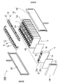
- FIG. 1 is a schematic perspective view of the power supply device
- FIG. 2 is an exploded perspective view thereof
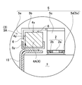
- FIGS. 3 and 4 are an enlarged perspective view and a vertical cross-sectional view showing a connecting structure of a bus bar and an electrode terminal, respectively.
- the power supply device 100 shown in FIGS. 1 and 2 is connected to a plurality of battery cells 1 having positive and negative electrode terminals 2 and electrode terminals 2 of the plurality of battery cells 1 to connect the plurality of battery cells 1 in parallel and in series.
- a bus bar 3 is provided, and a plurality of battery cells 1 are connected in parallel and in series via these bus bars 3.
- the battery cell 1 is a rechargeable secondary battery.
- a plurality of battery cells 1 are connected in parallel to form a parallel battery group, and a plurality of parallel battery groups are connected in series to connect a large number of battery cells 1 in parallel and in series.
- a plurality of battery cells 1 are laminated to form a battery block 10.
- the battery block 10 is fixed by a fixing component 13, and a plurality of battery cells 1 are laminated. It is fixed in the state.
- the fixing component 13 is a pair of end plates 14 arranged on both end faces of the stacked battery cells 1, and the end portions are connected to the end plates 14 to fix the stacked battery cells 1 in a pressurized state. It is provided with a fastening member 15.
- the battery cell 1 is a square battery having a quadrangular outer shape of a main surface having a wide surface, and is thinner than the width. Further, the battery cell 1 is a secondary battery that can be charged and discharged, and is a lithium ion secondary battery. However, the present invention does not specify the battery cell as a square battery, nor does it specify a lithium ion secondary battery. As the battery cell, all rechargeable batteries, for example, a non-aqueous electrolyte secondary battery other than the lithium ion secondary battery, a nickel aqueous battery cell, and the like can also be used.
- the battery cell 1 is one in which an electrode body in which positive and negative electrode plates are laminated is housed in an outer can 1a, filled with an electrolytic solution, and airtightly sealed.
- the outer can 1a is formed into a square cylinder that closes the bottom, and the upper opening is airtightly closed by a metal plate sealing plate 1b.
- the outer can 1a is manufactured by deep drawing a metal plate such as aluminum or an aluminum alloy.
- the sealing plate 1b is made of a metal plate such as aluminum or an aluminum alloy, like the outer can 1a.
- the sealing plate 1b is inserted into the opening of the outer can 1a, irradiates a laser beam at the boundary between the outer periphery of the sealing plate 1b and the inner circumference of the outer can 1a, and the sealing plate 1b is laser welded to the outer can 1a. It is fixed airtightly.
- Electrode terminal 2 In the battery cell 1, the sealing plate 1b, which is the top surface, is used as the terminal surface 1X, and the positive and negative electrode terminals 2 are fixed to both ends of the terminal surface 1X. As shown in FIGS. 3 and 4, the positive and negative electrode terminals 2 are fixed to the sealing plate 1b via the insulating material 18 and are connected to the built-in positive and negative electrode plates (not shown), respectively.
- the positive and negative electrode terminals 2 are provided with a welded surface 2b around the protruding portion 2a.
- the welded surface 2b has a flat shape parallel to the surface of the sealing plate 1b, and a protruding portion 2a is provided at the center of the welded surface 2b.
- the protruding portion does not necessarily have to be cylindrical, and although not shown, it may be polygonal or elliptical. It can also be applied to electrode terminals that do not have protrusions.
- the positions of the positive and negative electrode terminals 2 fixed to the sealing plate 1b of the battery cell 1 are such that the positive electrode and the negative electrode are symmetrical.
- the battery cells 1 are inverted left and right and stacked, and the electrode terminals 2 of the positive electrode and the negative electrode that are adjacent to each other are connected by the bus bar 3, so that the adjacent battery cells 1 can be connected in series. ..
- the vertical direction is specified in the figure. That is, as shown in the figure, the height direction of the battery cell in a state where the bottom surface of the outer can of the battery cell is the lower surface and the terminal surface provided with the electrode terminals is the upper surface is the vertical direction.
- Battery block 10 The plurality of battery cells 1 are laminated with each other to form a battery block 10.
- the battery blocks in the figure are stacked in the thickness direction of a plurality of battery cells 1 which are square batteries.
- a plurality of battery cells 1 are laminated so that the terminal surface 1X provided with the positive and negative electrode terminals 2 and the sealing plate 1b in the figure are flush with each other.
- the battery block 10 has an insulating spacer 16 sandwiched between the stacked battery cells 1.
- the insulating spacer 16 in the figure is made of an insulating material such as resin in the form of a thin plate or sheet.
- the insulating spacer 16 shown in the figure has a plate shape having a size substantially equal to that of the facing surface of the battery cell 1, and the insulating spacer 16 is laminated between the battery cells 1 adjacent to each other to connect the adjacent battery cells 1 to each other. Insulated.
- a spacer having a shape in which a flow path of a cooling gas is formed between the battery cell 1 and the spacer can also be used.
- the surface of the battery cell 1 can be covered with an insulating material.
- the surface of the outer can excluding the electrode portion of the battery cell may be heat-welded with a shrink tube such as PET resin.
- the insulating spacer 16 may be omitted.
- the power supply device 100 since a plurality of battery cells are connected in multiple parallel and multiple series, the insulating spacers 16 are sandwiched between the battery cells connected in series with each other. Since there is no voltage difference between adjacent outer cans between battery cells connected in parallel, it is possible to omit the insulating spacer between these battery cells.
- end plates 14 are arranged on both end faces of the battery block 10 with end face spacers 17 interposed therebetween.
- the end face spacer 17 is arranged between the battery block 10 and the end plate 14 to insulate the end plate 14 from the battery block 10.
- the end face spacer 17 is made of an insulating material such as resin in the form of a thin plate or sheet.
- the end face spacer 17 shown in the figure is laminated between the battery cell 1 arranged at both ends of the battery block 10 and the end plate 14 in a size and shape capable of covering the entire facing surface of the square battery cell 1.
- a metal bus bar 3 is connected to the positive and negative electrode terminals 2 of the adjacent battery cells 1, and a plurality of battery cells 1 are connected in parallel and in series via the bus bar 3.
- the battery blocks 10 are laminated so that the positive and negative electrode terminals 2 provided at both ends of the terminal surface 1X are oriented in the same direction on the left and right.
- a plurality of battery cells 1 are stacked so that the positive and negative electrode terminals 2 provided at both ends of the terminal surface 1X are oriented in opposite directions. There is.
- 12 battery cells 1 are stacked in the thickness direction to form a battery block 10, and two battery cells 1 are connected in parallel to form a parallel battery group.
- 6 sets of parallel battery groups are connected in series, and 12 battery cells 1 are connected in 2 parallel 6 series. Therefore, in the battery block 10 shown in FIG. 2, two battery cells 1 constituting the parallel battery group are laminated so that the positive and negative electrode terminals 2 are oriented in the same direction on the left and right, and two batteries are laminated in the same direction.
- Six sets of parallel battery groups consisting of the battery cells 1 of the above are stacked so that the positive and negative electrode terminals 2 are alternately oriented in opposite directions.
- the power supply device of the present invention does not specify the number of battery cells constituting the battery block and the connection state thereof.
- the power supply device can also variously change the number of battery cells constituting the battery block and the connection state thereof.
- the electrode terminals 2 of the plurality of battery cells 1 adjacent to each other are connected by the bus bar 3.
- a plurality of battery cells 1 are connected in parallel and in series.
- the bus bar 3 has an arm portion 5 connected to a rod portion 4.
- the rod portion 4 and the arm portion 5 are welded and connected, or, as will be described in detail later, one metal plate is processed and connected to an integral structure.
- a metal having low electrical resistance and light weight for example, aluminum, an aluminum alloy, a copper plate, a copper alloy, or an alloy thereof can be used.
- the bus bar does not necessarily have to be made of metal, and any other material having low electrical resistance and elastically deformable, for example, conductive plastic such as CFRP can also be used.
- the power supply device of this embodiment has a unique structure of a bus bar 3 for connecting electrode terminals 2 of a plurality of battery cells 1.
- the bus bar 3 is a plurality of stacked battery cells 1 and is connected to electrode terminals 2 of battery cells 1 arranged adjacent to each other to connect a large number of battery cells 1 in parallel or in series.
- the bus bar 3 shown in FIGS. 1 to 4 is the upper surface of the battery block 10 and is arranged so as to face the terminal surface 1X of the battery cell 1, and a plurality of battery cells 1 are stacked on both sides of the battery block 10.
- the electrode terminals 2 of the plurality of battery cells 1 arranged in the direction are connected substantially linearly.
- a plurality of arm portions 5 are connected to one rod portion 4, and adjacent battery cells 1 are electrically connected via the arm portion 5 and the rod portion 4.
- the tip portion 5x is welded to the electrode terminal 2 and the rear end portion 5y is connected to the rod portion 4.
- the plurality of arm portions 5 are connected at right angles to the rod portion 4 and arranged in parallel to each other, and the tip portion 5x is welded to the electrode terminal 2.
- the bus bar 3 is connected to the rod portion 4 so that the arm portion 5 can be elastically deformed.
- the elastically deformable arm portion 5 displaces the tip portion 5x.
- the displaced tip portion 5x absorbs the misalignment of the electrode terminal 2 and arranges the tip portion 5x and the electrode terminal 2 at ideal positions.
- the tip portion 5x and the electrode terminal 2 arranged at ideal positions are closely attached to each other without gaps and are reliably welded.
- the rod portion 4 for electrically connecting the arm portion 5 has a larger cross section than the arm portion 5, and the arm portion 5 is electrically connected with a small electric resistance to reduce power loss due to a large current.
- a pair of rod portions 4 are arranged in parallel on the battery block 10, that is, facing the sealing plate 1b of the battery cell 1.
- the rod portion 4 is arranged at a fixed position of the battery block 10 via the arm portion 5, or is arranged at a fixed position of the battery block 10 via an insulating holder (not shown).
- the pair of rod portions 4 are arranged outside the positive and negative electrode terminals 2 in an insulated state from the battery cell 1. Since the rod portion 4 electrically connects the stacked battery cells 1 via the arm portion 5, the rod portion 4 is arranged in a posture extending in the arrangement direction of the battery cells 1.
- the rod portion 4 is a rod material that is thicker than the arm portion 5 and does not elastically deform, and since currents from a plurality of arm portions 5 flow into the rod portion 4, the cross-sectional area is larger than that of the arm portion 5, the electrical resistance is smaller, and the rod portion 4 does not melt due to heat generation.
- a straight metal rod is suitable.
- the rod portion 4 does not necessarily have a square columnar shape, and as shown in the perspective view of FIG. 7, the rod portion 4B can have a columnar shape or an elliptical columnar shape.
- the rear end portion 5y of the arm portion 5 is welded and fixed to the surface of the curved outer peripheral surface on the side surface side of the columnar metal rod.
- the rod portion 4 can be formed into a linear rod shape by winding a metal plate 7 and laminating it in a spiral shape.
- the rod portion 4C has a small electrical resistance by laminating metal plates 7 in a spiral shape to increase the cross section.
- the rod portion 4C having the surface as the metal plate 7 can have the arm portion 5 as an integral structure.
- the bus bar 3C having the metal plate 7 spirally formed into the rod portion 4C can be manufactured by cutting the metal plate 7 and then winding the metal plate 7 in a spiral shape to form the rod portion 4C and the arm portion 5 as an integral structure.
- the wound metal plate 7 is cut into a shape in which a plurality of arm portions 5 project in parallel to one side edge of the quadrangular region 7A which is wound to form the rod portion 4C.
- the quadrangular region 7A can be manufactured by winding it in a spiral shape.
- the bus bar 3C which uses the arm portion 5 and the rod portion 4C as one metal plate 7, connects the arm portion 5 and the rod portion 4C in an ideal state to increase the strength of the connecting portion and the electricity of the connecting portion. It has the feature that resistance can be reduced.
- the bus bar 3H shown in FIG. 13 has a configuration in which one rod portion 4 and a plurality of arm portions 5 are integrally molded. Specifically, the rod portion 4 and the arm portion 5 are made of one metal plate, and the cross-sectional area of the rod portion 4 is increased by increasing the width or thickness of the rod portion 4 with respect to the arm portion 5. are doing.
- the arm portion may be made thinner than the rod portion by rolling or the like so that the bus bar and the electrode terminal can be adhered to each other without a gap and reliably welded. Further, the bus bar 3H is configured to allow both horizontal displacement and vertical displacement by providing a curved portion formed by bending both the rod portion 4 and the arm portion 5. ..
- the rod portion 4 of the bus bar 3 has a tubular shape and a linear tubular portion 4a, 4b, 4c formed by bending the metal plate 7. It can also be composed of metal columnar portions 4d and 4e inserted inside the portions 4a, 4b and 4c.
- the columnar portions 4d and 4e are press-fitted into the tubular portions 4a, 4b, and 4c formed by forming the metal plate 7 into a tubular shape, and the tubular portions 4a, 4b, and 4c are formed.
- the columnar portions 4d and 4e have an integrated structure.
- the tubular portions 4a, 4b and 4c and the columnar portions 4d and 4e can be made of the same metal or different metals.
- These rod portions 4D, 4E, and 4F have a large cross-sectional area by integrally connecting the tubular portions 4a, 4b, and 4c formed of the metal plate 7 and the metal columnar portions 4d, 4e. , The electrical resistance is reduced.
- the quadrangular region 7A is bent into a cylindrical shape to form tubular portions 4a and 4b, and the columnar portion 4d is press-fitted inside the tubular portions 4a and 4b.
- the rod portion 4E shown in FIG. 10 is provided with a slit 4s in a part of the cylindrical tubular portion 4b so that the rod portion 4E is easily elastically deformed and has a structure in which the columnar portion 4d can be smoothly press-fitted inside.
- the tubular portion 4b is provided with a slit 4s by providing a gap between facing measuring edges when the quadrangular region 7A of the metal plate 7 is bent into a cylindrical shape.
- the arm portion 5 connected to the measuring edge on one side of the quadrangular region 7A is folded 180 degrees with respect to the quadrangular region 7A so that the opening of the slit 4s is not blocked by the arm portion 5, and the columnar portion 4d is formed in the slit 4s. I am trying to guide you.
- the bus bars 3F and 3G shown in FIGS. 11 and 12 have an integral structure in which a square columnar columnar portion 4e is inserted into a tubular portion 4c formed by bending a metal plate 7 into a square tubular shape.
- the bus bars 3F and 3G obtained by bending the metal plate 7 into a prismatic shape to form a tubular portion 4c can be manufactured by bending the metal plate 7 to form a rod portion 4F and an arm portion 5 as an integral structure.
- the bus bar 3F is made of metal so that a plurality of arm portions 5 project in parallel on one side edge of a quadrangular region 7A which is bent to form a tubular portion 4c. After cutting the plate 7, the quadrangular region 7A is bent into a square tubular shape to form a tubular portion 4c, and the columnar portion 4e is press-fitted inside the tubular portion 4c to manufacture the plate 7.
- the bus bars 3D, 3E, 3F, and 3G having the tubular portions 4a, 4b, 4c of the rod portions 4D, 4E, and 4F and the arm portion 5 as one metal plate 7 are the rod portions 4D, 4E.
- the arm portion 5 is a conductive plate that can be elastically deformed, such as an elastic metal plate, and has a structure that can be elastically deformed to displace the tip portion 5x.
- the arm portion 5 capable of displacing the tip portion 5x can move the position of the tip portion 5x to an optimum position for welding of the electrode terminals 2 whose relative positions are displaced due to a dimensional error or the like.
- the arm portion 5 is provided with a deformation gap 6 between the arm portion 5 and the rod portion 4 in order to increase the amount of displacement of the tip portion 5x due to elastic deformation.
- the deformation gap 6 between the rod portion 4 and the rod portion 4 lengthens the region where the arm portion 5 elastically deforms, and increases the displacement due to the elastic deformation.
- the arm portion 5 of FIGS. 4 to 6, 11 and 12 is provided with a deformation gap 6 between the vertical plane 4y and the horizontal plane 4x of the prismatic rod portion 4 having the horizontal plane 4x, and the rear end is a rod. It is connected to the part 4.
- the arm portion 5 is provided with a deformation gap 6 between the rod portion 4 and the horizontal plane 4x on the upper side, and in the figure, the displacement amount at which the tip portion 5x can move up and down is increased.
- the tip portion 5x of the arm portion 5 is allowed to be displaced in the vertical direction.
- the arm portion 5 that can displace the tip portion 5x up and down has the tip portion 5x arranged at the optimum position of the electrode terminal 2 of the battery cell 1 that is displaced vertically, and the relative position between the tip portion 5x and the electrode terminal 2 is ideal. Can be placed in a suitable position and welded.
- the tip portion 5x is welded to the electrode terminal 2 by a method such as spot welding or laser welding, but in any of the welding methods, the tip portion 5x and the electrode terminal 2 can be welded in close contact with each other without any gap.
- the arm portion 5 capable of vertically displace the tip portion 5x can be arranged by moving the tip portion 5x to the position of the electrode terminal 2 even if the relative position of the electrode terminal 2 shifts up and down due to a dimensional error.
- the tip portion 5x that is in close contact with the electrode terminal 2 without a gap can energize both the tip portion 5x and the electrode terminal 2 in an ideal state in a spot-welded state, and can reliably heat-weld both of them on the contact surface. Even in laser welding, the tip portion 5x that is in close contact with the electrode terminal 2 without a gap is reliably heat-welded by melting the close portion with a laser beam. In spot welding and laser welding, the tip portion 5x is pressed against the electrode terminal 2 and heat-welded in a state of being in close contact with each other. Therefore, the arm portion 5 capable of elastically deforming and moving the tip portion 5x to the electrode terminal 2 is the tip portion 5x. Can be reliably heat-welded to the electrode terminal 2 without any gaps. It is strong against impact and vibration because there is a deformation gap even after welding.
- a deformation gap 6 is provided between the rod portion 4 and the vertical surface 4y, and the rear end (lower end in the drawing) is the rod portion. It is connected to 4.
- the arm portion 5 in these figures is bent from the horizontal plane 4x of the rod portion 4 to a shape along the vertical plane 4y to provide a deformation gap 6 between the horizontal plane 4x of the rod portion 4 and the vertical plane 4y. In this way, by providing the deformation gap 6 between the vertical surface 4y which is the side surface of the rod portion 4 and the arm portion 5, the tip portion 5x of the arm portion 5 is allowed to be displaced in the horizontal direction.
- the tip portion 5x of the arm portion 5 can be displaced even if the electrode terminal 2 is displaced in the horizontal plane, the tip portion 5x can be displaced even if the electrode terminal 2 is displaced in the horizontal plane due to an error in the manufacturing process. It can be moved to the correct position of the electrode terminal 2 and welded reliably, and is strong against impact and vibration.
- a deformation gap 6 is provided between the upper surface or the side surface which is the outer peripheral surface of the columnar rod portion 4. It is provided and the rear end is connected to the rod portion 4.
- These bus bars 3 also allow the tip portion 5x of the arm portion 5 to be displaced in the vertical direction by providing a deformation gap 6 between the upper surface of the rod portion 4 and the arm portion 5, and also with the side surface of the rod portion 4. By providing a deformation gap 6 between the arm portion 5 and the arm portion 5, the tip portion 5x of the arm portion 5 is allowed to be displaced in the horizontal direction.
- the arm portions 5A shown in FIGS. 4 to 11 are arranged on the side surface side of the rod portion 4, and the connecting arm portion 5a in which the rear end portion 5y is connected to the rod portion 4 and the upper end of the connecting arm portion 5a.
- the arm portion 5A can displace the welded portion 5d, which is the tip portion 5x, in the horizontal plane in the horizontal direction orthogonal to the stacking direction of the battery cells 1.
- the displacement of the electrode terminal 2 of the battery cell 1 in the X-axis direction (the stacking direction of the battery cell 1 in the figure) and the Y-axis direction (the direction orthogonal to the stacking direction in the figure) is corrected, and the tip portion 5x is an electrode. It has the feature that it can be welded to the terminal 2.
- the arm portion 5B shown in FIG. 12 is arranged on the side surface side of the rod portion 4, and is connected to the connecting arm portion 5a in which the rear end portion 5y is connected to the rod portion 4 and the upper end of the connecting arm portion 5a.
- the horizontal arm portion 5b extending beyond the upper surface of the rod portion 4 toward the tip side, the plate-shaped vertical arm portion 5c connected to the tip edge of the horizontal arm portion 5b, and the vertical arm portion 5c in a horizontal posture.
- a welded portion 5d connected to the above is provided.
- the horizontal arm portion 5b is not affected by the distance between the electrode terminals of the battery cells 1 stacked on each other.
- the width (d) of the welded portion 5d and the total length (t) of the welded portion 5d can be increased.
- the arm portion 5B having this structure can be suitably used for the arm portion 5 formed of the metal plate 7 and integrally connected to the rod portion 4.
- the total length (h) of the vertical arm portion 5c can be set large.
- the above power supply device is most suitable for a vehicle power supply that supplies electric power to a motor that runs an electric vehicle.
- an electric vehicle equipped with a power supply device an electric vehicle such as a hybrid vehicle or a plug-in hybrid vehicle that runs on both an engine and a motor, or an electric vehicle that runs only on a motor can be used, and is used as a power source for these electric vehicles. Will be done.
- FIG. 14 shows an example in which a power supply device is mounted on a hybrid vehicle that runs on both an engine and a motor.
- the vehicle HV equipped with the power supply device shown in this figure includes a vehicle body 91, an engine 96 for traveling the vehicle body 91, a motor 93 for traveling, and wheels driven by these engines 96 and a motor 93 for traveling. It includes 97, a power supply device 100 that supplies electric power to the motor 93, and a generator 94 that charges the battery of the power supply device 100.
- the power supply device 100 is connected to the motor 93 and the generator 94 via the DC / AC inverter 95.
- the vehicle HV runs on both the motor 93 and the engine 96 while charging and discharging the battery of the power supply device 100.
- the motor 93 is driven to drive the vehicle in a region where the engine efficiency is low, for example, when accelerating or traveling at a low speed.
- the motor 93 is driven by being supplied with electric power from the power supply device 100.
- the generator 94 is driven by the engine 96 or by regenerative braking when braking the vehicle to charge the battery of the power supply device 100.
- the vehicle HV may include a charging plug 98 for charging the power supply device 100. By connecting the charging plug 98 to an external power source, the power supply device 100 can be charged.
- FIG. 15 shows an example in which a power supply device is mounted on an electric vehicle traveling only by a motor.
- the vehicle EV equipped with the power supply device shown in this figure supplies electric power to the vehicle body 91, the running motor 93 for running the vehicle body 91, the wheels 97 driven by the motor 93, and the motor 93.
- a power supply device 100 for charging and a generator 94 for charging the battery of the power supply device 100 are provided.
- the power supply device 100 is connected to the motor 93 and the generator 94 via the DC / AC inverter 95.
- the motor 93 is driven by being supplied with electric power from the power supply device 100.
- the generator 94 is driven by the energy used for regenerative braking of the vehicle EV to charge the battery of the power supply device 100. Further, the vehicle EV is provided with a charging plug 98, and the charging plug 98 can be connected to an external power source to charge the power supply device 100.
- the power supply device for power storage device
- the present invention does not specify the use of the power supply device as the power source of the motor for traveling the vehicle.
- the power supply device according to the embodiment can also be used as a power source for a power storage device that charges and stores a battery with electric power generated by solar power generation, wind power generation, or the like.
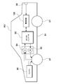
- FIG. 16 shows a power storage device in which the battery of the power supply device 100 is charged by the solar cell 82 to store electricity.
- the power storage device shown in FIG. 16 charges the battery of the power supply device 100 with the electric power generated by the solar cell 82 arranged on the roof or roof of a building 81 such as a house or factory.
- This power storage device uses the solar cell 82 as a power source for charging, charges the battery of the power supply device 100 with the charging circuit 83, and then supplies power to the load 86 via the DC / AC inverter 85. Therefore, this power storage device has a charge mode and a discharge mode.
- the DC / AC inverter 85 and the charging circuit 83 are connected to the power supply device 100 via the discharge switch 87 and the charging switch 84, respectively.
- the ON / OFF of the discharge switch 87 and the charge switch 84 is switched by the power controller 88 of the power storage device.
- the power controller 88 switches the charging switch 84 to ON and the discharge switch 87 to OFF to allow the charging circuit 83 to charge the power supply device 100.
- the power controller 88 turns off the charging switch 84 and turns on the discharge switch 87 to switch to the discharge mode, and the power supply device 100 Allows discharge from to load 86.
- the charge switch 84 can be turned on and the discharge switch 87 can be turned on to supply power to the load 86 and charge the power supply device 100 at the same time.
- the power supply device can also be used as a power source for a power storage device that charges and stores batteries by using midnight power at night.
- a power supply device charged with midnight power can be charged with midnight power, which is surplus power of a power plant, and output power in the daytime when the power load is large, so that the peak power in the daytime can be limited to a small value.
- the power supply can also be used as a power source for charging with both solar cell output and midnight power. This power supply device can effectively utilize both the power generated by the solar cell and the midnight power, and can efficiently store electricity while considering the weather and power consumption.
- the above-mentioned power storage devices include backup power supply devices that can be mounted in computer server racks, backup power supply devices for wireless base stations such as mobile phones, power storage power supplies for homes or factories, power supplies for street lights, etc. It can be suitably used for power storage devices combined with solar cells, backup power sources for traffic lights and road traffic indicators, and the like.
- the power supply device is suitably used as a power source for a large current used for a power source of a motor for driving an electric vehicle such as a hybrid car, a plug-in hybrid car, an electric vehicle, a fuel cell vehicle, or an electric motorcycle.
- a power supply device for a plug-in hybrid electric vehicle, a hybrid electric vehicle, an electric vehicle, or the like that can switch between an EV driving mode and a HEV driving mode can be mentioned.
- a backup power supply device that can be mounted on a computer server rack, a backup power supply device for wireless base stations such as mobile phones, a power storage device for home use and factories, a power supply for street lights, etc. , Can also be used as appropriate for backup power supplies such as traffic lights.
- 100 ... Power supply device 1 ... Battery cell, 1X ... Terminal surface, 1a ... Exterior can, 1b ... Seal plate, 2 ... Electrode terminal, 2a ... Protruding part, 2b ... Welded surface, 3, 3A, 3B, 3C, 3D, 3E, 3F, 3G, 3H ... Bus bar, 4, 4A, 4B, 4C, 4D, 4E, 4F ... Rod part, 4a, 4b, 4c ... Cylindrical part, 4d, 4e ... Column part, 4s ... Slit, 4x ... Horizontal plane, 4y ... Vertical surface, 5, 5A, 5B ... Arm part, 5a ... Connecting arm part, 5b ...
Landscapes
- Engineering & Computer Science (AREA)
- Chemical & Material Sciences (AREA)
- General Chemical & Material Sciences (AREA)
- Chemical Kinetics & Catalysis (AREA)
- Electrochemistry (AREA)
- Manufacturing & Machinery (AREA)
- Power Engineering (AREA)
- Life Sciences & Earth Sciences (AREA)
- Sustainable Development (AREA)
- Sustainable Energy (AREA)
- Transportation (AREA)
- Mechanical Engineering (AREA)
- Aviation & Aerospace Engineering (AREA)
- Microelectronics & Electronic Packaging (AREA)
- Materials Engineering (AREA)
- Connection Of Batteries Or Terminals (AREA)
- Battery Mounting, Suspending (AREA)
Abstract
Description
本発明の実施形態1に係る電源装置を図1ないし図4に示す。これらの図において、図1は電源装置の概略斜視図を、図2はその分解斜視図を、図3と図4はバスバーと電極端子の連結構造を示す拡大斜視図及び垂直横断面図をそれぞれ示している。図1と図2に示す電源装置100は、正負の電極端子2を備える複数の電池セル1と、これら複数の電池セル1の電極端子2に接続されて、複数の電池セル1を並列かつ直列に接続するバスバー3とを備え、これらのバスバー3を介して複数の電池セル1を並列かつ直列に接続している。電池セル1は、充放電可能な二次電池である。電源装置100は、複数の電池セル1が並列に接続されて並列電池グループを構成すると共に、複数の並列電池グループが直列に接続されて、多数の電池セル1が並列かつ直列に接続される。図1と図2に示す電源装置100は、複数の電池セル1を積層して電池ブロック10を形成しており、この電池ブロック10を固定部品13で固定して、複数の電池セル1を積層状態に固定している。固定部品13は、積層している電池セル1の両端面に配置される一対のエンドプレート14と、このエンドプレート14に、端部を連結して積層状態の電池セル1を加圧状態に固定している締結部材15とを備えている。
電池セル1は、幅広面である主面の外形を四角形とする角形電池であって、幅よりも厚さを薄くしている。さらに、電池セル1は、充放電できる二次電池であって、リチウムイオン二次電池としている。ただし、本発明は、電池セルを角形電池には特定せず、またリチウムイオン二次電池にも特定しない。電池セルには、充電できる全ての電池、たとえばリチウムイオン二次電池以外の非水系電解液二次電池やニッケル水電池セルなども使用できる。
電池セル1は、天面である封口板1bを端子面1Xとして、この端子面1Xの両端部に正負の電極端子2を固定している。正負の電極端子2は、図3と図4に示すように、絶縁材18を介して封口板1bに固定されており、内蔵する正負の電極板(図示せず)にそれぞれ接続されている。正負の電極端子2は、突出部2aの周囲に溶接面2bを設けている。溶接面2bは、封口板1bの表面と平行な平面状で、この溶接面2bの中央部に突出部2aを設けている。図3の電極端子2は、突出部2aを円柱状としている。ただ、突出部は、必ずしも円柱状とする必要はなく、図示しないが、多角柱状又は楕円柱状とすることもできる。また、突出部がない電極端子にも適用できる。
複数の電池セル1は、互いに積層されて電池ブロック10を構成している。図 の電池ブロックは、角形電池である複数の電池セル1の厚さ方向に積層している。電池ブロック10は、正負の電極端子2を設けている端子面1X、図にあっては封口板1bが同一平面となるように、複数の電池セル1を積層している。
バスバー3は、図5及び図6に示すように、ロッド部4にアーム部5を連結している。ロッド部4とアーム部5は溶着して連結され、あるいは、詳細には後述するが、1枚の金属板を加工して一体構造に連結している。ロッド部4とアーム部5は、電気抵抗が小さく、軽量である金属、例えばアルミニウム、アルミニウム合金、銅板、銅合金、あるいはこれらの合金が使用できる。ただし、バスバーは、必ずしも金属製とする必要はなく、電気抵抗が小さくて弾性変形できる他の全ての材料、たとえばCFRP等の導電性プラスチックも使用できる。
図14は、エンジンとモータの両方で走行するハイブリッド車に電源装置を搭載する例を示す。この図に示す電源装置を搭載した車両HVは、車両本体91と、この車両本体91を走行させるエンジン96及び走行用のモータ93と、これらのエンジン96及び走行用のモータ93で駆動される車輪97と、モータ93に電力を供給する電源装置100と、電源装置100の電池を充電する発電機94とを備えている。電源装置100は、DC/ACインバータ95を介してモータ93と発電機94に接続している。車両HVは、電源装置100の電池を充放電しながらモータ93とエンジン96の両方で走行する。モータ93は、エンジン効率の悪い領域、例えば加速時や低速走行時に駆動されて車両を走行させる。モータ93は、電源装置100から電力が供給されて駆動する。発電機94は、エンジン96で駆動され、あるいは車両にブレーキをかけるときの回生制動で駆動されて、電源装置100の電池を充電する。なお、車両HVは、図14に示すように、電源装置100を充電するための充電プラグ98を備えてもよい。この充電プラグ98を外部電源と接続することで、電源装置100を充電できる。
また、図15は、モータのみで走行する電気自動車に電源装置を搭載する例を示す。この図に示す電源装置を搭載した車両EVは、車両本体91と、この車両本体91を走行させる走行用のモータ93と、このモータ93で駆動される車輪97と、このモータ93に電力を供給する電源装置100と、この電源装置100の電池を充電する発電機94とを備えている。電源装置100は、DC/ACインバータ95を介してモータ93と発電機94に接続している。モータ93は、電源装置100から電力が供給されて駆動する。発電機94は、車両EVを回生制動する時のエネルギーで駆動されて、電源装置100の電池を充電する。また車両EVは充電プラグ98を備えており、この充電プラグ98を外部電源と接続して電源装置100を充電できる。
さらに、本発明は、電源装置の用途を、車両を走行させるモータの電源には特定しない。実施形態に係る電源装置は、太陽光発電や風力発電等で発電された電力で電池を充電して蓄電する蓄電装置の電源として使用することもできる。図16は、電源装置100の電池を太陽電池82で充電して蓄電する蓄電装置を示す。
Claims (17)
- 複数の電池セルをバスバーで電気接続してなる電源装置であって、
前記バスバーは、
前記電池セルの配列方向に伸びる導電性のロッド部と、
前記ロッド部に連結してなる弾性変形するアーム部とを備え、
前記アーム部は、
先端部が前記電池セルの電極端子に溶着されて、後端部を前記ロッド部に連結しており、
前記ロッド部を介して複数の前記電池セルを電気接続しており、さらに、
前記アーム部は、
弾性変形できる導電性プレートで、
前記ロッド部との間であって前記後端部から先端側に変形隙間を設けており、
前記アーム部が弾性変形して、
前記電極端子に溶着される前記先端部を変位できる構造としてなることを特徴とする電源装置。 - 請求項1に記載する電源装置であって、
前記アーム部の先端部が、前記電極端子に積層して溶着されてなる電源装置。 - 請求項1または2に記載する電源装置であって、
前記変形隙間が、
前記アーム部の先端部の上下方向の変位を許容するように前記ロッド部との間に設けられてなることを特徴とする電源装置。 - 請求項1ないし3のいずれかに記載する電源装置であって、
前記変形隙間が、
前記アーム部の先端部の水平方向の変位を許容するように前記ロッド部との間に設けられてなることを特徴とする電源装置。 - 請求項1ないし4のいずれかに記載する電源装置であって、
前記アーム部が、前記ロッド部の側面であって、前記電極端子と反対側の側面に前記後端部を連結して、前記ロッド部との間に前記変形隙間を設けてなることを特徴とする電源装置。 - 請求項1ないし5のいずれかに記載する電源装置であって、
前記ロッド部が、
多角柱状又は円柱状であることを特徴とする電源装置。 - 請求項1ないし6のいずれかに記載する電源装置であって、
前記ロッド部が、垂直面を有する柱状で、
前記アーム部が、前記ロッド部の垂直面に前記後端部を連結して、前記ロッド部の垂直面との間に前記変形隙間を設けてなることを特徴とする電源装置。 - 請求項1ないし7のいずれかに記載する電源装置であって、
前記ロッド部が、垂直面と水平面とを有する角柱状で、
前記アーム部が、前記ロッド部の水平面から垂直面に沿う形状で、
前記ロッド部の垂直面に前記アーム部の後端部を連結して、前記ロッド部の水平部との間に前記変形隙間を設けてなることを特徴とする電源装置。 - 請求項1ないし8のいずれかに記載する電源装置であって、
前記ロッド部が、柱状の金属ロッドで、
前記アーム部の後端部を、前記ロッド部に溶着して固定してなることを特徴とする電源装置。 - 請求項1ないし9のいずれかに記載する電源装置であって、
前記ロッド部は、金属板を巻回して渦巻き状に積層しており、
前記アーム部は、前記金属板に一体的に連結されてなることを特徴とする電源装置。 - 請求項1ないし9のいずれかに記載する電源装置であって、
前記ロッド部は、
金属板を曲げ加工して筒状に形成された筒状部と、
前記筒状部の内部に挿入された柱状部とで構成されており、
前記アーム部は、
前記金属板に一体的に連結されてなることを特徴とする電源装置。 - 請求項10または11に記載する電源装置であって、
前記金属板は、展開された状態において、
前記ロッド部を構成する、外形を四角形とする四角形領域と、
前記四角形領域のひとつの側縁から突出する複数のアーム部と、を有する形状に裁断されてなることを特徴とする電源装置。 - 請求項1ないし12のいずれかに記載する電源装置であって、
前記電池セルが外装缶の開口部を封口板で閉塞してなる角形電池であって、複数の前記電池セルを積層して電池ブロックとしており、
前記封口板は、正負の電極端子を設けており、
前記正負の電極端子の外側に、一対の前記ロッド部が配置され、
一対の前記ロッド部は、前記封口板の上面であって、前記電池セルの配列方向に伸びて配置され、
前記アーム部が、前記ロッド部から前記電極端子に伸びて、前記先端部を電極端子に溶着してなることを特徴とする電源装置。 - 請求項1ないし13のいずれかに記載する電源装置であって、
前記アーム部が、
前記ロッド部の側面側に配置されて、前記後端部が該ロッド部に連結されてなる連結アーム部と、
前記連結アーム部の上端に連結されて、ロッド部の上面を超えて先端側に向かって伸びる水平アーム部と、
前記水平アーム部の側縁に連結してなる板状の垂直アーム部と、
前記垂直アーム部に水平姿勢に連結してなる溶着部とを備え、
前記溶着部が、前記電極端子に積層状態で溶着されてなることを特徴とする電源装置。 - 請求項1ないし13のいずれかに記載する電源装置であって、
前記アーム部が、
前記ロッド部の側面側に配置されて、前記後端部が該ロッド部に連結されてなる連結アーム部と、
前記連結アーム部の上端に連結されて、前記ロッド部の上面を超えて先端側に向かって伸びる水平アーム部と、
前記水平アーム部の先端縁に連結してなる板状の垂直アーム部と、
前記垂直アーム部に水平姿勢に連結してなる溶着部とを備え、
前記溶着部が、前記電極端子に積層状態で溶着されてなることを特徴とする電源装置。 - 請求項1ないし15のいずれか一に記載の電源装置を備える電動車両であって、
前記電源装置と、該電源装置から電力供給される走行用のモータと、該電源装置及び前記モータを搭載してなる車両本体と、該モータで駆動されて前記車両本体を走行させる車輪とを備えることを特徴とする電源装置を備える電動車両。 - 請求項1ないし15のいずれか一に記載の電源装置を備える蓄電装置であって、
前記電源装置と、該電源装置への充放電を制御する電源コントローラを備えており、
前記電源コントローラでもって、外部からの電力により前記電池セルへの充電を可能とすると共に、前記電池セルに対し充電を行うよう制御することを特徴とする蓄電装置。
Priority Applications (4)
| Application Number | Priority Date | Filing Date | Title |
|---|---|---|---|
| US17/438,519 US11978924B2 (en) | 2019-03-27 | 2019-08-26 | Power supply device, electric vehicle comprising power supply device, and power storage device |
| JP2021508686A JP7348270B2 (ja) | 2019-03-27 | 2019-08-26 | 電源装置と電源装置を備える電動車両及び蓄電装置 |
| CN201980094647.6A CN113614996B (zh) | 2019-03-27 | 2019-08-26 | 电源装置、具备电源装置的电动车辆和蓄电装置 |
| EP19921386.9A EP3951914B1 (en) | 2019-03-27 | 2019-08-26 | Power supply device, electric vehicle comprising power supply device, and power storage device |
Applications Claiming Priority (2)
| Application Number | Priority Date | Filing Date | Title |
|---|---|---|---|
| JP2019060107 | 2019-03-27 | ||
| JP2019-060107 | 2019-03-27 |
Publications (1)
| Publication Number | Publication Date |
|---|---|
| WO2020194783A1 true WO2020194783A1 (ja) | 2020-10-01 |
Family
ID=72610678
Family Applications (1)
| Application Number | Title | Priority Date | Filing Date |
|---|---|---|---|
| PCT/JP2019/033263 Ceased WO2020194783A1 (ja) | 2019-03-27 | 2019-08-26 | 電源装置と電源装置を備える電動車両及び蓄電装置 |
Country Status (5)
| Country | Link |
|---|---|
| US (1) | US11978924B2 (ja) |
| EP (1) | EP3951914B1 (ja) |
| JP (1) | JP7348270B2 (ja) |
| CN (1) | CN113614996B (ja) |
| WO (1) | WO2020194783A1 (ja) |
Cited By (4)
| Publication number | Priority date | Publication date | Assignee | Title |
|---|---|---|---|---|
| CN115312939A (zh) * | 2021-05-07 | 2022-11-08 | 新盛力科技股份有限公司 | 电池导电架及电池模块 |
| JP2022169375A (ja) * | 2021-04-27 | 2022-11-09 | トヨタ自動車株式会社 | 組電池とその製造方法 |
| WO2025115575A1 (ja) * | 2023-11-28 | 2025-06-05 | パナソニック株式会社 | 電池パック及び電動工具 |
| WO2025234344A1 (ja) * | 2024-05-07 | 2025-11-13 | 株式会社Honda・GS Yuasa EV Battery R&D | 蓄電装置 |
Families Citing this family (6)
| Publication number | Priority date | Publication date | Assignee | Title |
|---|---|---|---|---|
| US11509010B2 (en) * | 2020-01-31 | 2022-11-22 | Toyota Motor Engineering & Manufacturing North America, Inc. | Rotatable terminal plate housing assemblies and methods thereof |
| WO2021199488A1 (ja) * | 2020-03-31 | 2021-10-07 | 三洋電機株式会社 | 電源装置及びこれを備える車両並びに蓄電装置 |
| CN114665205B (zh) * | 2022-05-20 | 2022-08-23 | 嘉兴模度新能源有限公司 | 一种均衡承压电池组及其制备方法及结构一体化电池箱 |
| US20250112336A1 (en) * | 2022-05-27 | 2025-04-03 | Electric Power Systems, Inc. | Interconnected battery connection devices and methods of operation |
| CN115084764B (zh) * | 2022-08-01 | 2024-05-24 | 深圳市泽塔电源系统有限公司 | 一种电池组 |
| CN116505202A (zh) * | 2023-05-29 | 2023-07-28 | 惠州亿纬锂能股份有限公司 | 汇流排、集成母排及电池模组 |
Citations (8)
| Publication number | Priority date | Publication date | Assignee | Title |
|---|---|---|---|---|
| JP2010257735A (ja) * | 2009-04-24 | 2010-11-11 | Toyota Motor Corp | 組電池 |
| JP2011228216A (ja) * | 2010-04-22 | 2011-11-10 | Yazaki Corp | 配線材 |
| WO2014064888A1 (ja) * | 2012-10-26 | 2014-05-01 | 三洋電機株式会社 | 電源装置及び電源装置を備える電動車両並びに蓄電装置、電源装置の製造方法 |
| JP2015023003A (ja) * | 2013-07-23 | 2015-02-02 | 三洋電機株式会社 | バッテリ装置とこのバッテリ装置を備える電動車両及び蓄電装置 |
| JP2015111537A (ja) * | 2013-10-28 | 2015-06-18 | 株式会社オートネットワーク技術研究所 | 配線モジュール |
| JP2016213026A (ja) | 2015-05-07 | 2016-12-15 | エネルギー コントロール リミテッドEnergy Control Limited | 二本の導電プレートにより複数の二次電池が並列接続されて構成される組み立て電池の構造 |
| WO2018116822A1 (ja) * | 2016-12-22 | 2018-06-28 | 株式会社オートネットワーク技術研究所 | バスバー、蓄電モジュール、および、配線モジュール |
| WO2019187312A1 (ja) * | 2018-03-30 | 2019-10-03 | 三洋電機株式会社 | 電池モジュール及びこれを備える車両並びにバスバー |
Family Cites Families (6)
| Publication number | Priority date | Publication date | Assignee | Title |
|---|---|---|---|---|
| JP2012243689A (ja) * | 2011-05-23 | 2012-12-10 | Sanyo Electric Co Ltd | 電源装置、電源装置を備える車両並びにバスバー |
| JP6040728B2 (ja) * | 2012-11-21 | 2016-12-07 | Tdk株式会社 | ブスバー基板及びブスバー基板を用いた電池モジュール |
| US10749161B2 (en) * | 2016-09-23 | 2020-08-18 | Artisan Vehicle Systems Inc. | Unified connection array for battery module |
| CN206116506U (zh) * | 2016-10-18 | 2017-04-19 | 许继电源有限公司 | 电池组及其极流片 |
| DE102017115589B3 (de) * | 2017-07-12 | 2019-01-03 | Lisa Dräxlmaier GmbH | Batterie für ein fahrzeug sowie verfahren |
| KR102273184B1 (ko) * | 2017-10-10 | 2021-07-05 | 주식회사 엘지에너지솔루션 | 전극 리드 접합용 버스바 조립체 및 이를 포함하는 배터리 모듈 |
-
2019
- 2019-08-26 CN CN201980094647.6A patent/CN113614996B/zh active Active
- 2019-08-26 WO PCT/JP2019/033263 patent/WO2020194783A1/ja not_active Ceased
- 2019-08-26 EP EP19921386.9A patent/EP3951914B1/en active Active
- 2019-08-26 JP JP2021508686A patent/JP7348270B2/ja active Active
- 2019-08-26 US US17/438,519 patent/US11978924B2/en active Active
Patent Citations (8)
| Publication number | Priority date | Publication date | Assignee | Title |
|---|---|---|---|---|
| JP2010257735A (ja) * | 2009-04-24 | 2010-11-11 | Toyota Motor Corp | 組電池 |
| JP2011228216A (ja) * | 2010-04-22 | 2011-11-10 | Yazaki Corp | 配線材 |
| WO2014064888A1 (ja) * | 2012-10-26 | 2014-05-01 | 三洋電機株式会社 | 電源装置及び電源装置を備える電動車両並びに蓄電装置、電源装置の製造方法 |
| JP2015023003A (ja) * | 2013-07-23 | 2015-02-02 | 三洋電機株式会社 | バッテリ装置とこのバッテリ装置を備える電動車両及び蓄電装置 |
| JP2015111537A (ja) * | 2013-10-28 | 2015-06-18 | 株式会社オートネットワーク技術研究所 | 配線モジュール |
| JP2016213026A (ja) | 2015-05-07 | 2016-12-15 | エネルギー コントロール リミテッドEnergy Control Limited | 二本の導電プレートにより複数の二次電池が並列接続されて構成される組み立て電池の構造 |
| WO2018116822A1 (ja) * | 2016-12-22 | 2018-06-28 | 株式会社オートネットワーク技術研究所 | バスバー、蓄電モジュール、および、配線モジュール |
| WO2019187312A1 (ja) * | 2018-03-30 | 2019-10-03 | 三洋電機株式会社 | 電池モジュール及びこれを備える車両並びにバスバー |
Cited By (5)
| Publication number | Priority date | Publication date | Assignee | Title |
|---|---|---|---|---|
| JP2022169375A (ja) * | 2021-04-27 | 2022-11-09 | トヨタ自動車株式会社 | 組電池とその製造方法 |
| JP7597635B2 (ja) | 2021-04-27 | 2024-12-10 | トヨタ自動車株式会社 | 組電池の製造方法 |
| CN115312939A (zh) * | 2021-05-07 | 2022-11-08 | 新盛力科技股份有限公司 | 电池导电架及电池模块 |
| WO2025115575A1 (ja) * | 2023-11-28 | 2025-06-05 | パナソニック株式会社 | 電池パック及び電動工具 |
| WO2025234344A1 (ja) * | 2024-05-07 | 2025-11-13 | 株式会社Honda・GS Yuasa EV Battery R&D | 蓄電装置 |
Also Published As
| Publication number | Publication date |
|---|---|
| EP3951914A4 (en) | 2022-07-06 |
| JPWO2020194783A1 (ja) | 2020-10-01 |
| EP3951914B1 (en) | 2026-04-08 |
| CN113614996A (zh) | 2021-11-05 |
| US11978924B2 (en) | 2024-05-07 |
| CN113614996B (zh) | 2024-03-15 |
| EP3951914A1 (en) | 2022-02-09 |
| US20220131236A1 (en) | 2022-04-28 |
| JP7348270B2 (ja) | 2023-09-20 |
Similar Documents
| Publication | Publication Date | Title |
|---|---|---|
| JP7348270B2 (ja) | 電源装置と電源装置を備える電動車両及び蓄電装置 | |
| US11777178B2 (en) | Battery module, vehicle provided with same, and bus bar | |
| CN110268552B (zh) | 电源装置 | |
| JP6907131B2 (ja) | 電源装置及びこれを用いる車両並びにバスバー | |
| US11289773B2 (en) | Power supply device, vehicle using same, bus bar, and electrical connection method for battery cell using same bus bar | |
| JP6239523B2 (ja) | 電源装置及び電源装置を備える電動車両並びに蓄電装置、電源装置の製造方法 | |
| KR20090095949A (ko) | 전지모듈의 전극단자 접속부재 | |
| WO2020194937A1 (ja) | 電源装置及びこれを用いた電動車両並びに蓄電装置 | |
| CN112272884B (zh) | 电池组件和具备该电池组件的车辆 | |
| JP7276894B2 (ja) | 電源装置及びこれを備える車両並びに緩衝体 | |
| CN113632300B (zh) | 电源装置和使用该电源装置的电动车辆以及蓄电装置 | |
| WO2021024772A1 (ja) | 電源装置及びこれを用いた電動車両並びに蓄電装置 | |
| JPWO2020059296A1 (ja) | 電源装置及び電源装置を備える車両並びに蓄電装置 | |
| WO2020026962A1 (ja) | 電源装置及びこれを備える車両 | |
| WO2020202671A1 (ja) | 電源装置及びこれを用いた電動車両並びに蓄電装置、電源装置用締結部材、電源装置の製造方法、電源装置用締結部材の製造方法 | |
| US12132219B2 (en) | Power supply device, electric vehicle and power storage device including power supply device, and method of manufacturing power supply device | |
| JP7532066B2 (ja) | 電源装置及びこれを備える車両並びに蓄電装置 | |
| WO2020194930A1 (ja) | 電源装置及びこれを用いた電動車両並びに蓄電装置 | |
| CN113632305A (zh) | 电源装置和使用该电源装置的电动车辆以及蓄电装置、电源装置用紧固构件、电源装置的制造方法、电源装置用紧固构件的制造方法 |
Legal Events
| Date | Code | Title | Description |
|---|---|---|---|
| 121 | Ep: the epo has been informed by wipo that ep was designated in this application |
Ref document number: 19921386 Country of ref document: EP Kind code of ref document: A1 |
|
| ENP | Entry into the national phase |
Ref document number: 2021508686 Country of ref document: JP Kind code of ref document: A |
|
| NENP | Non-entry into the national phase |
Ref country code: DE |
|
| ENP | Entry into the national phase |
Ref document number: 2019921386 Country of ref document: EP Effective date: 20211027 |
|
| WWG | Wipo information: grant in national office |
Ref document number: 2019921386 Country of ref document: EP |