WO2020195262A1 - 作業機械 - Google Patents
作業機械 Download PDFInfo
- Publication number
- WO2020195262A1 WO2020195262A1 PCT/JP2020/005257 JP2020005257W WO2020195262A1 WO 2020195262 A1 WO2020195262 A1 WO 2020195262A1 JP 2020005257 W JP2020005257 W JP 2020005257W WO 2020195262 A1 WO2020195262 A1 WO 2020195262A1
- Authority
- WO
- WIPO (PCT)
- Prior art keywords
- boundary line
- work tool
- target surface
- speed
- work
- Prior art date
- Legal status (The legal status is an assumption and is not a legal conclusion. Google has not performed a legal analysis and makes no representation as to the accuracy of the status listed.)
- Ceased
Links
Images






Classifications
-
- E—FIXED CONSTRUCTIONS
- E02—HYDRAULIC ENGINEERING; FOUNDATIONS; SOIL SHIFTING
- E02F—DREDGING; SOIL-SHIFTING
- E02F3/00—Dredgers; Soil-shifting machines
- E02F3/04—Dredgers; Soil-shifting machines mechanically-driven
- E02F3/28—Dredgers; Soil-shifting machines mechanically-driven with digging tools mounted on a dipper- or bucket-arm, i.e. there is either one arm or a pair of arms, e.g. dippers, buckets
- E02F3/36—Component parts
- E02F3/42—Drives for dippers, buckets, dipper-arms or bucket-arms
- E02F3/43—Control of dipper or bucket position; Control of sequence of drive operations
-
- E—FIXED CONSTRUCTIONS
- E02—HYDRAULIC ENGINEERING; FOUNDATIONS; SOIL SHIFTING
- E02F—DREDGING; SOIL-SHIFTING
- E02F9/00—Component parts of dredgers or soil-shifting machines, not restricted to one of the kinds covered by groups E02F3/00 - E02F7/00
- E02F9/26—Indicating devices
- E02F9/261—Surveying the work-site to be treated
- E02F9/262—Surveying the work-site to be treated with follow-up actions to control the work tool, e.g. controller
-
- E—FIXED CONSTRUCTIONS
- E02—HYDRAULIC ENGINEERING; FOUNDATIONS; SOIL SHIFTING
- E02F—DREDGING; SOIL-SHIFTING
- E02F3/00—Dredgers; Soil-shifting machines
- E02F3/04—Dredgers; Soil-shifting machines mechanically-driven
- E02F3/28—Dredgers; Soil-shifting machines mechanically-driven with digging tools mounted on a dipper- or bucket-arm, i.e. there is either one arm or a pair of arms, e.g. dippers, buckets
- E02F3/36—Component parts
- E02F3/3604—Devices to connect tools to arms, booms or the like
- E02F3/3677—Devices to connect tools to arms, booms or the like allowing movement, e.g. rotation or translation, of the tool around or along another axis as the movement implied by the boom or arms, e.g. for tilting buckets
- E02F3/3681—Rotators
-
- E—FIXED CONSTRUCTIONS
- E02—HYDRAULIC ENGINEERING; FOUNDATIONS; SOIL SHIFTING
- E02F—DREDGING; SOIL-SHIFTING
- E02F3/00—Dredgers; Soil-shifting machines
- E02F3/04—Dredgers; Soil-shifting machines mechanically-driven
- E02F3/28—Dredgers; Soil-shifting machines mechanically-driven with digging tools mounted on a dipper- or bucket-arm, i.e. there is either one arm or a pair of arms, e.g. dippers, buckets
- E02F3/36—Component parts
- E02F3/42—Drives for dippers, buckets, dipper-arms or bucket-arms
- E02F3/43—Control of dipper or bucket position; Control of sequence of drive operations
- E02F3/435—Control of dipper or bucket position; Control of sequence of drive operations for dipper-arms, backhoes or the like
-
- E—FIXED CONSTRUCTIONS
- E02—HYDRAULIC ENGINEERING; FOUNDATIONS; SOIL SHIFTING
- E02F—DREDGING; SOIL-SHIFTING
- E02F9/00—Component parts of dredgers or soil-shifting machines, not restricted to one of the kinds covered by groups E02F3/00 - E02F7/00
- E02F9/20—Drives; Control devices
- E02F9/22—Hydraulic or pneumatic drives
- E02F9/2203—Arrangements for controlling the attitude of actuators, e.g. speed, floating function
-
- E—FIXED CONSTRUCTIONS
- E02—HYDRAULIC ENGINEERING; FOUNDATIONS; SOIL SHIFTING
- E02F—DREDGING; SOIL-SHIFTING
- E02F9/00—Component parts of dredgers or soil-shifting machines, not restricted to one of the kinds covered by groups E02F3/00 - E02F7/00
- E02F9/20—Drives; Control devices
- E02F9/22—Hydraulic or pneumatic drives
- E02F9/2278—Hydraulic circuits
- E02F9/2285—Pilot-operated systems
-
- E—FIXED CONSTRUCTIONS
- E02—HYDRAULIC ENGINEERING; FOUNDATIONS; SOIL SHIFTING
- E02F—DREDGING; SOIL-SHIFTING
- E02F9/00—Component parts of dredgers or soil-shifting machines, not restricted to one of the kinds covered by groups E02F3/00 - E02F7/00
- E02F9/20—Drives; Control devices
- E02F9/22—Hydraulic or pneumatic drives
- E02F9/2278—Hydraulic circuits
- E02F9/2296—Systems with a variable displacement pump
Definitions
- the present invention relates to a work machine such as a hydraulic excavator.
- some work machines such as hydraulic excavators have a machine control function that controls the position and posture of work mechanisms such as booms, arms, and buckets so that they move along the design surface. ..
- work mechanisms such as booms, arms, and buckets
- Civil engineering construction management standards stipulate standard values for allowable accuracy in the height direction with respect to the design surface. If the error in the finished shape of the design surface exceeds the permissible value, the work efficiency will decrease due to the re-construction. Therefore, the machine control function is required to have the control accuracy required to satisfy the allowable accuracy of the finished product.
- Patent Document 1 discloses a method of controlling the tilt rotation axis of the rotary tilt bucket.
- the shovel control device shown in Patent Document 1 automatically controls the tilt angle of the bucket so that the bucket line defined on the bucket and the slope of the design surface are parallel to each other.
- the design surface is composed of a plurality of surfaces whose normal directions of the surfaces are significantly different, and there is a possibility that the bucket will pass through a plurality of continuous surfaces in one shaping operation.
- the bucket maintains line contact with the next surface in order to maintain the finished shape accuracy even after the surface is switched. There is a need.
- the present invention has been made in view of the above problems, and an object of the present invention is to maintain a line contact state between the work tool and each target surface when the work tool passes the boundary line between two adjacent target surfaces. By doing so, it is an object of the present invention to provide a work machine capable of improving the shaping accuracy near the boundary line.
- the present invention includes a work tool, at least one position control actuator for controlling the position of the work tool, and at least one attitude control actuator for controlling the posture of the work tool.
- the actuator an operation device for instructing the operation of the plurality of actuators, a controller for outputting a control signal for controlling at least one of the plurality of actuators based on the operation amount of the operation device, and a plurality of target surfaces.
- the controller includes a design surface storage device that stores information on the design surface, and the controller extracts a first target surface, which is the target surface closest to the work tool, from the plurality of target surfaces, and the first target surface.
- the controller uses the first target among the plurality of target surfaces.
- a second target surface which is a target surface adjacent to the surface, is extracted, a first boundary line, which is a boundary line between the first target surface and the second target surface, is calculated, and the actuator sets the first boundary line.
- the control signal of the attitude control actuator shall be corrected so that the angle difference between the reference line set on the work tool and the first boundary line becomes small.
- the angle difference between the reference line set on the work tool and the boundary line between the two adjacent target surfaces is calculated, and before the work tool passes through the boundary line.
- the posture of the work tool is controlled so that the angle difference between the reference line and the boundary line becomes small.
- the line contact state between the work tool and each target surface is maintained, so that the shape near the boundary line is shaped. It is possible to improve the accuracy.
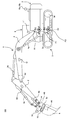
- FIG. 1 is a diagram schematically showing the appearance of the hydraulic excavator 100 according to the first embodiment of the present invention.
- the hydraulic excavator 100 is an articulated front device (front working machine) configured by connecting a plurality of rotating driven members (boom 4, arm 5, bucket (working tool) 6).
- the upper swivel body 2 and the lower traveling body 3 constituting the vehicle body are provided, and the upper swivel body 2 is provided so as to be rotatable with respect to the lower traveling body 3.
- the base end of the boom 4 of the front device 1 is rotatably supported by the front portion of the upper swing body 2, and one end of the arm 5 rotates to an end portion (tip) different from the base end of the boom 4.
- the bucket 6 is rotatably supported at the other end of the arm 5.
- an operation lever device (operation device) 9a for outputting an operation signal for operating the hydraulic actuators 2a, 4a to 6a, 6b, 6c (shown in FIG. 2) and a traveling motor
- An operation lever device (operation device) 9b for outputting an operation signal for driving 3a is provided.
- the operating lever device 9a is two operating levers that can be tilted back and forth and left and right, and operates the hydraulic actuators 2a, 4a to 6a according to the tilting direction and the tilting amount.
- the operating lever device 9a includes two physical switches capable of outputting continuous signals, and outputs electrical signals for operating the hydraulic actuators 6b and 6c.
- the operating lever device 9b is two operating levers that can be tilted in the front-rear direction, and operates the hydraulic actuator 3a according to the tilting direction and the tilting amount.
- the operation lever devices 9a and 9b include a detection device that electrically detects an operation signal corresponding to the tilt amount (lever operation amount) of the operation lever, and the detected lever operation amount is a control device controller 10 (FIG. 3). (Shown in)) is output via electrical wiring.
- the operation of the hydraulic actuators 2a to 6a, 6b, 6c is controlled by controlling the direction and flow rate of the hydraulic oil supplied from the hydraulic pump 7 driven by the prime mover 40 to the hydraulic actuators 2a to 6a, 6b, 6c. It is performed by controlling with.
- the control valve 8 is controlled by a drive signal (pilot pressure) output from the pilot pump 70 (shown in FIG. 3) via the electromagnetic proportional valve.
- the operation of each of the hydraulic actuators 2a to 6a, 6b, 6c is controlled by controlling the electromagnetic proportional valve with the controller 10 based on the electric signal of the operating lever operating amount detected by the operating lever devices 9a, 9b.
- the operating lever devices 9a and 9b may be of a hydraulic pilot system different from the above, and the pilot pressure according to the operating direction and operating amount of the operating lever is directly supplied to the control valve 8 as a drive signal to each hydraulic pressure. It may be configured to drive the actuators 2a to 6a.
- FIG. 2 is a diagram schematically showing the drive mechanism of the hydraulic excavator 100.
- the hydraulic excavator 100 is defined with a coordinate system F1 fixed to the upper swing body 2 and a coordinate system F2 fixed to the lower traveling body 3.
- the coordinate system F1 and the coordinate system F2 are coordinate systems in which the z-axis directions are the same and the origin position is offset in the z-axis direction.
- the boom 4 and arm 5 operate on a single plane (hereinafter, operating plane) by driving the boom cylinder 4a and arm cylinder 5a.
- the operation plane is a plane orthogonal to the rotation axis A1 of the boom 4 and the rotation axis A2 of the arm 5, and is defined as the xz plane of the upper swing body coordinate system F1.
- the operation plane rotates according to the rotation operation of the upper swing body 2 by rotating the swing motor 2a around the rotation shaft A3.
- the bucket 6 can control the posture of the bucket 6 in the roll, pitch, and yaw directions by driving the bucket cylinder 6a, the tilt cylinder 6b, and the rotary motor 6c.
- the roll direction is the rotation direction around the X axis of the upper swivel coordinate system F1
- the pitch direction is the rotation direction around the Y axis of the upper swivel coordinate system F1
- the yaw direction is around the Z axis of the upper swirl coordinate system F1. Is defined as the direction of rotation of.
- Inertial measurement units 11 to 14 measure angular velocity and acceleration.
- the vehicle body inertial measurement unit 11, the boom inertial measurement unit 12, the arm inertial measurement unit 13, and the bucket inertial measurement unit 14 estimate the rotation angles and angular velocities around the rotation axes A1 to A5 based on the measured angular velocities and accelerations.
- the rotary angle measuring device 15 measures the rotation angle around the rotation shaft A6.
- the angle detecting means is not limited to the inertial measuring devices 11 to 14.
- stroke sensors are arranged on the boom cylinder 4a, the arm cylinder 5a, the bucket cylinder 6a, and the tilt cylinder 6b, and the rotation axes A1, A2, and A4 are arranged.
- the rotation angle may be calculated by a conversion formula based on the relative relationship between the amount of rotation around A5 and the amount of cylinder stroke.
- GNSS antennas 16a and 16b are attached to the upper swing body 2 in order to acquire the vehicle body position Pg and the vehicle body orientation Cg.
- the GNSS antennas 16a and 16b transmit a distance signal received from an artificial satellite or the like to a positioning device 200 described later.
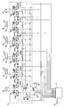
- FIG. 3 is a diagram schematically showing a hydraulic actuator control system mounted on the hydraulic excavator 100. For simplification of the description, only the elements necessary for the description of the invention are described.
- the hydraulic actuator control system includes a control valve 8 for driving each of the hydraulic actuators 2a to 6a, 6b, 6c, a hydraulic pump 7 for supplying pressure oil to the control valve 8, and a pilot for supplying pilot pressure as a drive signal for the control valve 8. It is composed of a pump 70 and a prime mover 40 for driving a hydraulic pump 7.
- the hydraulic pump 7 is of a variable displacement type, and the capacity of the hydraulic pump 7 is adjusted by operating the electromagnetic proportional pressure reducing valve 7a for the variable displacement pump based on the current command from the controller 10, and the hydraulic pump 7 It is assumed that the discharge flow rate of is controlled.
- the hydraulic pump 7 may be of a fixed capacitance type, and the rotation speed of the prime mover 40 may be adjusted by a control command from the controller 10 to control the discharge flow rate of the hydraulic pump 7.
- the pressure oil discharged by the hydraulic pump 7 is dealt with by the swivel direction control valve 8a1, the boom direction control valve 8a3, the arm direction control valve 8a5, the bucket direction control valve 8a7, the tilt direction control valve 8a9, and the rotary direction control valve 8a11, respectively. It is distributed to the hydraulic actuators 2a to 6a, 6b, 6c.
- the direction control valves 8a1, The pilot pressure for driving 8a3, 8a5, 8a7, 8a9, 8a11 is adjusted.
- one of the oil passages connected to the swivel motor 2a is an opening communicating with the hydraulic pump 7 (meter-in opening), and the other is an opening communicating with the oil passage connecting to the tank 41 (meter-out opening).
- the electromagnetic proportional pressure reducing valve 8a2a or the electromagnetic proportional pressure reducing valve 8a2b By selecting whether to drive the electromagnetic proportional pressure reducing valve 8a2a or the electromagnetic proportional pressure reducing valve 8a2b, the direction of the pressure oil flowing inside the swivel motor 2a is reversed, and the rotation direction of the swivel motor 2a can be controlled. Since the same applies to the rotary direction control valve 8a11, the description thereof will be omitted.
- one of the bottom side oil chamber 4a1 or the rod side oil chamber 4a2 of the boom cylinder 4a becomes an opening (meter-in opening) communicating with the oil passage connected to the hydraulic pump 7, and the other becomes a tank 41. It is an opening (meter-out opening) that communicates with the connecting oil passage.
- the electromagnetic proportional pressure reducing valve 8a4b when the electromagnetic proportional pressure reducing valve 8a4b is driven, the pressure oil flows from the hydraulic pump 7 to the rod side oil chamber 4a2, and the pressure oil in the bottom side oil chamber 4a1 is returned to the tank 41.
- the electromagnetic proportional pressure reducing valve 8a4a or the electromagnetic proportional pressure reducing valve 8a4b by selecting whether to drive the electromagnetic proportional pressure reducing valve 8a4a or the electromagnetic proportional pressure reducing valve 8a4b, the operating direction of the boom cylinder 4a is reversed, and the driving direction of the boom cylinder 4a can be controlled.
- a part of the pressure oil discharged from the hydraulic pump 7 is discharged to the tank 41 by the bleed-off valve 8b1 communicating the oil passage to the tank 41.
- the pilot pressure of the bleed-off valve 8b1 is adjusted by operating the electromagnetic proportional pressure reducing valve 8b2 for the bleed-off valve based on the current command commanded from the controller 10, and the flow rate discharged to the tank 41 is controlled.
- the directional control valves 8a1, 8a3, 8a5, 8a7, 8a9, 8a11 are used as open center type directional control valves capable of opening control in three directions, with meter-in opening and meter-out.
- the bleed-off opening may be adjusted in conjunction with the opening.
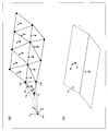
- FIG. 4 is a diagram showing details of the definitions of the design surface TS and the target surface S.
- the design surface TS is defined by Vt1, Vt2, and Vt3, which are three position coordinate points with reference to the global coordinate system F3 set outside the hydraulic excavator 100.
- Vt1, Vt2, and Vt3 are three position coordinate points with reference to the global coordinate system F3 set outside the hydraulic excavator 100.
- the center of gravity position Pt of the triangle and the normal vector Nt are calculated with respect to the design surface TS.
- the center of gravity position Pt and the normal vector Nt are calculated for each design surface TS, and as shown in FIG. 4B, the design surfaces TS having a small angle between the normal vectors Nt are combined into one. It is newly defined as the target surface S.
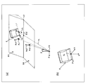
- FIG. 5 is a diagram showing details of definitions of calculated values related to the target surfaces S1 and S2 and the work tool 6.
- the state of the work tool 6 is composed of a position X b , a posture C b , and a translation speed (movement speed) V b .
- the attitude C b is defined as the rotation angles of the roll, pitch, and yaw directions with respect to the lower traveling body coordinate system F2, and the angle ⁇ r in the roll direction, the angle ⁇ p in the pitch direction, and the angle ⁇ y in the yaw direction.
- C b ( ⁇ r , ⁇ p , ⁇ y ) is constructed from the three elements of, and is expressed as shown in FIG. 5 (b).
- the translation velocity V b is the translation velocity of the reference point P1 of the work tool 6 with reference to the lower traveling body coordinate system F2, and is the velocity v x in the x direction, the velocity v y in the y direction, and the velocity v z in the z direction.
- V b (v x, v y, v z) and.
- the rotation speeds in the roll, pitch, and yaw directions are omitted because they are not used in this embodiment.
- the translational speed V b will be referred to as “moving speed V b " below.
- a reference line L1 is preset on the work tool 6.
- the cutting edge of the work tool 6 is defined as the reference line L1.
- the calculation related to the attitude control of the work tool 6 is performed based on the main target surface S1 and the predicted target surface S2.
- the main target surface S1 is defined as the target surface S having the shortest vertical line drawn from the reference point P1 of the work tool 6.
- the predicted target surface S2 is defined as the target surface S which is in the moving speed Vb direction of the work tool 6 and has the smallest vertical distance drawn from the reference point P1 to the boundary line with the main target surface S1.
- the Euclidean norm of the moving speed V b of the working tool 6 is smaller than the threshold values V b, th , the boundary line from the reference point P1 to the main target surface S1 regardless of the moving speed V b direction of the working tool 6.
- the target surface S having the shortest vertical line distance is defined as the predicted target surface S2.
- These two target planes S1 and S2 are calculated with reference to the lower traveling body coordinate system F2.
- the conversion from the global coordinate system F3 in which the calculation related to the target surface S is performed to the lower traveling body coordinate system F2 in which the calculation related to the target surfaces S1 and S2 is performed is the vehicle body position Pg acquired from the positioning device 200 described later and the vehicle body. It is performed based on the orientation Cg.
- the boundary line L2 between the target surfaces S1 and S2 is calculated from the main target surface S1 and the predicted target surface S2.
- Direction vector D L 2 as the outer product of the normal vector N S 2 of the normal vector N S 1 and the predicted target surface S2 of the main target surface S1, is calculated from the following formula (1).
- FIG. 6 is a functional block diagram showing details of the processing function of the controller 10 according to this embodiment. Note that, in FIG. 6, as in FIG. 3, functions not directly related to the present invention will be omitted.
- the controller 10 has a work tool state calculation unit 10a, a work tool reference line calculation unit 10b, a target surface calculation unit 10c, a boundary line calculation unit 10d, and a posture correction amount calculation unit 10e.
- the work tool state calculation unit 10a is based on the angles and angular velocities around the rotation axes A1 to A6 acquired from the measuring devices 11 to 15, and the position X b and the posture of the work tool 6 with reference to the lower traveling body coordinate system F2.
- C b and the moving velocity V b are calculated geometrically.
- the calculated position X b and posture C b are output to the work tool reference line calculation unit 10b and the target surface calculation unit 10c.
- the moving speed V b is output to the target surface calculation unit 10c.
- the work tool reference line calculation unit 10b calculates the direction vector D L 1 of the reference line L1 preset on the work tool 6 based on the position X b and the posture C b calculated by the work tool state calculation unit 10a. ..
- the calculated reference line L1 is output to the posture correction amount calculation unit 10e.
- the target surface calculation unit 10c is acquired from the design surface storage device 21 based on the vehicle body position Pg and vehicle body orientation Cg acquired from the positioning device 200, the position X b acquired from the work tool state calculation unit 10a, and the moving speed V b . from the design surface TS, extracts the primary target surface S1 and the prediction target surface S2, the reference position relative to the undercarriage coordinate system F2 P S 1, P S 2 , the normal vector N S 1, N S 2 Is calculated. The calculated calculated values related to the main target surface S1 and the predicted target surface S2 are output to the boundary line calculation unit 10d.
- the boundary line calculation unit 10d calculates the direction vector DL 2 from the equation (1) based on the calculation values related to the main target surface S1 and the predicted target surface S2 acquired from the target surface calculation unit 10c.
- the calculated calculated value related to the boundary line L2 is output to the posture correction amount calculation unit 10e.
- the posture correction amount calculation unit 10e is connected to the rotary motor 6c based on the reference line L1 acquired from the work tool reference line calculation unit 10b, the boundary line L2 acquired from the boundary line calculation unit 10d, and the operation signal acquired from the operation device 9a. Calculate the rotary command speeds ⁇ y and ref to be output.
- the shaping work performed by controlling the position X b of the work tool 6 is performed by the manual operation of the operation device 9a by the operator.
- the operator manually controls the drive ratios of the swivel motor 2a, the boom cylinder 4a, and the arm cylinder 5a to perform the shaping work.
- the controller 10 may be provided with an excavation control system that semi-automatically controls the swing motor 2a, the boom cylinder 4a, and the arm cylinder 5a according to the operation signal of the operation device 9a and the main target surface S1.
- the position X b of the work tool 6 is held in the region above and above the main target surface S1 in response to the operation signal of the operation device 9a, and does not invade below the main target surface S1.
- the control for forcibly operating at least one of the hydraulic actuators 2a, 4a, 5a for example, the boom cylinder 4a is extended to forcibly raise the boom
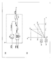
- FIG. 7 is a functional block diagram showing details of the processing function of the posture correction amount calculation unit 10e.
- FIG. 7A is a functional block diagram showing a processing flow of the posture correction amount calculation unit 10e.
- Posture correction amount calculation unit 10e has an angle difference calculation unit 10e1 for calculating the angular difference E L of the reference line direction vector L1 and the boundary direction vector L2.
- the sign of angle difference is calculated as the angular difference E L, for example, the following equation (2).
- the angle difference EL is the difference between the angle formed by the reference line direction vector DL 1 and the angle formed by the boundary line direction vector DL 2 with respect to the x-axis of the lower traveling body coordinate system F2. Defined.
- Angle difference angle difference calculation unit 10e1 is calculated based on E L, rotary compensation velocity omega y, mod is calculated as the following equation (3).
- k 1 is a gain representing the degree of correction rotary motor 6c for the angle difference E L.
- the calculated rotary correction speeds ⁇ y and mod and the rotary required speeds ⁇ y and req in which the rotary operation signals are converted by the table TBL1 are input to the selector SLT1.
- the selector SLT1 outputs the rotary request speeds ⁇ y and req as the rotary command speeds ⁇ y and ref when the rotary request speeds ⁇ y and req are given.
- the rotary correction speeds ⁇ y and mod are output as the rotary command speeds ⁇ y and ref .
- FIG. 8 is a diagram showing the operation of the work tool 6 by the posture correction of the posture correction amount calculation unit 10e.
- FIG. 8A0 is an example of the result of the operator adjusting the posture C b of the work tool 6 so that the main target surface S1 and the reference line L1 on the work tool 6 are in line contact state. From this state, the shaping work is started by the operator operating the operating device 9a, and the work tool 6 moves in the direction of the predicted target surface S2 at the moving speed V b .
- FIG. 8 (a1) and 8 (a2) show the main target surface S1 and the prediction in a state where the rotation angle of the rotary motor 6c is not corrected by the posture correction amount calculation unit 10e, starting from the state of FIG. 8 (a0).
- This is an example of the result when the target surface S2 is shaped.
- FIG. 8A1 in which the work tool 6 is in the upper region of the main target surface S1 and is close to the boundary line L2, the rotary correction speeds ⁇ y and mod of the posture correction amount calculation unit 10e to the rotary motor 6c are set. Since no command has been given, the shaping work of the main target surface S1 is performed in a state where the reference line L1 and the boundary line L2 on the work tool 6 are not parallel to each other.
- FIG. 8A1 in which the work tool 6 is in the upper region of the main target surface S1 and is close to the boundary line L2, the rotary correction speeds ⁇ y and mod of the posture correction amount calculation unit 10e to the rotary motor 6c are set
- FIG. 8 (b1) and 8 (b2) show the main target surface S1 and the main target surface S1 and FIG. 8 (b2) in a state where the rotation angle of the rotary motor 6c is corrected by the posture correction amount calculation unit 10e, starting from the state of FIG. 8 (a0). This is an example of the result when the shaping work of the prediction target surface S2 is performed.
- FIG. 8 (b1) in which the work tool 6 is in the upper region of the main target surface S1 and is close to the boundary line L2, the rotary correction speeds ⁇ y and mod of the posture correction amount calculation unit 10e to the rotary motor 6c are set.
- the shaping work of the main target surface S1 is performed in a state where the reference line L1 and the boundary line L2 on the work tool 6 are parallel to each other.
- the reference line L1 and the predicted target surface S2 are in line contact state after passing through the boundary line L2, and the predicted target surface S2 near the boundary line L2 is in line contact state. It is shaped by. Therefore, the shaping of the prediction target surface S2 near the boundary line L2 is realized in the line contact state, and the shaping accuracy near the boundary line L2 is improved.
- FIG. 9 is a diagram showing the effect of improving the shaping accuracy near the boundary line L2 by the present invention.
- the shaping error that occurs when the rotation angle of the rotary motor 6c is not corrected by the posture correction amount calculation unit 10e is a broken line
- the shaping error that occurs when the rotation angle of the rotary motor 6c is corrected by the posture correction amount calculation unit 10e is shown by a solid line.
- the shaping error is defined as the error between the target surfaces S1 and S2 and the height direction of the terrain after the shaping operation.
- the work tool 6 is in line contact with the main target surface S1. It is assumed that the operator manually corrects the posture C b of the work tool 6. In this case, there is no difference in the shaping error with respect to the main target surface S1 when there is no posture correction (broken line) and when there is (solid line).
- the controller 10 includes a controller 10 that outputs a control signal that controls at least one of 6, 6b, and 6c, and a design surface storage device 21 that stores information on a design surface composed of a plurality of target surfaces.
- the controller 10 includes the plurality of targets.
- the first target surface S1 which is the target surface closest to the work tool 6 is extracted from the surfaces, and at least one of the plurality of actuators is selected based on the position and orientation of the work tool 6 with respect to the first target surface S1.
- the controller 10 extracts the second target surface S2, which is the target surface adjacent to the first target surface S1, from the plurality of target surfaces, and the first target surface.
- the first boundary line L2, which is the boundary line between S1 and the second target surface S2, is calculated, and the reference line L1 and the first reference line L1 set on the work tool 6 before the work tool 6 passes through the first boundary line L2. as angular difference E L of the boundary line L2 is reduced, to correct the control signal of the attitude control actuator 6c.
- the reference line L2 which is set on the implement 6, the angular difference E L of the boundary line L2 between adjacent two target surfaces S1, S2
- the implement 6 before passing the boundary line L2 the angular difference E L of the reference line L1 and the boundary line L2 is the attitude of the implement 6 is controlled to be small.
- the line contact state between the work tool 6 and the target surfaces S1 and S2 is maintained, so that the shaping accuracy near the boundary line L2 can be improved. It becomes.
- FIG. 10 is a functional block diagram showing details of the processing function of the controller 10 according to the second embodiment.
- the controller 10 includes a position X b of the work tool 6 calculated by the work tool state calculation unit 10a, a reference line L1 calculated by the work tool reference line calculation unit 10b, a boundary line L2 calculated by the boundary line calculation unit 10d, and an operation device 9a. It has an operation speed correction unit 10f that corrects the movement speed V b of the work tool 6 based on the operation signal obtained from.
- the command speed calculated by the operation speed correction unit 10f is output to the swivel motor 2a, the boom cylinder 4a, and the arm cylinder 5a, which are actuators capable of controlling the position Xb of the work tool 6.
- FIG. 11 is a functional block diagram showing details of the processing function of the operating speed correction unit 10f according to the second embodiment.
- the functional block diagram of the operation speed correction unit 10f shown in FIG. 11A shows a required work tool speed calculation unit 10f1, a boundary line approach direction calculation unit 10f2, an angle difference calculation unit 10f3, a work tool speed limit unit 10f4, and a limit actuator speed. It is composed of a calculation unit 10f5.
- the required work tool speed calculation unit 10f1 calculates the required speeds V b and req of the reference point P1 set on the work tool 6 from the turning operation signal, the boom operation signal, and the arm operation signal acquired from the operation device 9a.
- the boundary line approach direction calculation unit 10f2 is based on the position X b of the work tool 6 calculated by the work tool state calculation unit 10a and the direction vector D L 2 of the boundary line L2 calculated by the boundary line calculation unit 10d.
- the direction vector (hereinafter, boundary line approaching direction vector) D b from the reference point P1 to the boundary line L2 is calculated.
- the boundary line approaching direction vector D b is a perpendicular direction drawn from the reference point P1 on the work tool 6 to the boundary line L2, and is given as a three-dimensional direction vector having an Euclidean norm of 1. Be done.
- Angular difference calculation section 10f3 based a direction vector D L 1 of the reference line L1 implement the reference line calculation unit 10b is calculated, the direction vector D L 2 boundary line L2 boundary calculating unit 10d is calculated, wherein The angle difference EL is calculated from (2).
- the implement speed limiting section 10f4 the reference line L1 and the angle difference E L Based on limited work implement speed V b of the boundary line L2, calculating the lim, border approach direction vector D b in the direction of required work implement speed V Limit b, req to the speed limit work tool speed V b, lim or less.
- the limiting work tool speeds V b, lim, and x in the x direction are calculated by the following equation (4).
- V b, max, x is a gain representing the deceleration degree of the moving speed V b of the work implement 6 for the implement 6 is translatable maximum speed in the x direction
- k 2 is the angular difference E L.
- the speed limit actuator speed calculation unit 10f5 decomposes the speed limit work tool speeds V b and lim output by the work tool speed limit unit 10f4 into speed commands for each of the swivel motor 2a, the boom cylinder 4a, and the arm cylinder 5a. Calculates boom speed command and arm speed command.
- the controller 10 when correcting the control signal of the attitude control actuators 6c, the reference line L1 of the first boundary line L2 angular difference E L increases, the side toward the first boundary line L2
- the control signals of the position control actuators 2a, 4a, and 5a are corrected so that the deceleration degree of the moving speed V b of the work tool 6 becomes large.
- the hydraulic excavator 100 according to the present embodiment configured as described above also has the same effect as that of the first embodiment.
- the greater angle difference E L is the reference line L1 and the first boundary line L2 since the deceleration degree of the moving speed V b of the working tool 6 on the side toward the first boundary line L2 is large, the posture correction amount calculation It is possible to prevent the work tool 6 from passing through the boundary line L2 before the correction of the posture C b of the work tool 6 by the portion 10e is completed. As a result, the line contact state of the work tool 6 with respect to the predicted target surface S2 after passing through the boundary line L2 can be reliably maintained, and the shaping accuracy in the vicinity of the boundary line L2 is guaranteed.
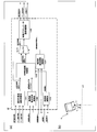
- FIG. 12 is a functional block diagram showing details of the processing function of the posture correction amount calculation unit 10e according to the third embodiment.
- the functional block diagram of the posture correction amount calculation unit 10e shown in FIG. 12A is composed of an angle difference calculation unit 10e1 and a boundary line distance calculation unit 10e2.
- Boundary distance calculator 10e2 calculates the distance E D 1 between the reference point P1 of the implement 6 with the boundary line L2.
- Distance E D 1 as shown in FIG. 12 (b), defined as the length of the perpendicular dropped from the reference point P1 of the working tool 6 to the boundary line L2.
- Distance E D 1 which boundary distance calculator 10e2 is calculated is output to the selector SLT2.
- the selector SLT2 selects one of the rotary request speed ⁇ y, req and the rotary correction speed ⁇ y, mod by the following method, and outputs the rotary command speed ⁇ y, ref .
- T D1 is a distance threshold value for determining whether or not to correct the rotation angle of the rotary motor 6c.
- the equation (5), the distance in the case E D 1 is not less than the threshold value T D1 is calculated by an operation signal requesting the implement speed omega y, req is output, yaw implement 6 according to the posture correction amount calculation unit 10e The orientation ⁇ y is not corrected.
- FIG. 13 is a functional block diagram showing details of the processing function of the operating speed correction unit 10f according to this embodiment.
- the functional block diagram of the operation speed correction unit 10f shown in FIG. 13A shows the required work tool speed calculation unit 10f1, the boundary line approach direction calculation unit 10f2, the angle difference calculation unit 10f3, the work tool speed limit unit 10f4, and the limit actuator speed. It is composed of a calculation unit 10f5 and a boundary line distance calculation unit 10f6.
- Boundary distance calculator 10f6 like the boundary distance calculator 10e2, calculates the distance E D 1 between the reference point P1 of the implement 6 with the boundary line L2.
- Distance E D 1 as shown in FIG. 13 (b), defined as the length of the perpendicular dropped from the reference point P1 of the working tool 6 to the boundary line L2.
- Distance E D 1 which boundary distance calculator 10f6 is calculated is output to the selector SLT3.
- the selector SLT3 selects one of the required work tool speed V b, req and the limited work tool speed V b, lim by the following method, and outputs the work tool command speed V b, ref .
- T D2 is a distance threshold value for determining whether or not to limit the moving speed V b .
- T D 2 is a distance threshold value for determining whether or not to limit the moving speed V b .
- the controller 10 calculates the first boundary line distance E D 1 is the distance from the reference point P1 set on the work tool 6 to the first boundary line L2, the first boundary line distance E D If 1 is less than the threshold value T D1, as angular difference E L of the reference line L1 and the first boundary line L2 is reduced, to correct the control signal of the attitude control actuator 6c.
- the controller 10 when the first boundary line distance E D 1 is less than the threshold value T D2, the moving speed V b is the speed limit V b of the implement 6, such that the following lim, position control actuator 2a, 4a, The control signal of 5a is corrected.
- the distance E D 1 is When the threshold value T D2 or more is set, the moving speed V b is not decelerated, so that it is possible to improve the work efficiency in a region far away from the boundary line L2.
- FIG. 14 is a functional block diagram showing details of the processing function of the operating speed correction unit 10f according to the fourth embodiment.
- the functional block diagram of the operation speed correction unit 10f shown in FIG. 14A shows the required work tool speed calculation unit 10f1, the boundary line approach direction calculation unit 10f2, the angle difference calculation unit 10f3, the work tool speed limit unit 10f4, and the limit actuator speed. It is composed of a calculation unit 10f5 and a boundary line approach speed calculation unit 10f7.
- the boundary line approach speed calculation unit 10f7 calculates speed components (hereinafter, boundary line approach speed) V b, L in the direction toward the boundary line L2 of the reference point P1 of the work tool 6. As shown in FIG. 14B, the boundary line approach speeds V b and L are defined as the components in the perpendicular direction drawn from the reference point P1 of the work tool 6 to the boundary line L2 with respect to the movement speed V b .
- the boundary line approach speeds V b and L calculated by the boundary line approach speed calculation unit 10f7 are output to the selector SLT4.
- the selector SLT4 selects one of the required work tool speed V b, req and the limited work tool speed V b, lim by the following method, and outputs the work tool command speed V b, ref .
- T V is the velocity of the threshold for determining whether to limit the movement speed V b.
- the controller 10 calculates the boundary line approach speeds V b, L , which are speed components in the direction toward the first boundary line L2 of the moving speed V b of the work tool 6, and the boundary line approach speed V b,
- L is equal to or greater than the threshold value T V
- the control signals of the position control actuators 2a, 4a, and 5a are corrected so that the moving speed V b of the work tool 6 is equal to or less than the limiting speed V b, lim .
- the work tool command speeds V b and ref are limited to the limited work tool speeds V b and lim . It is possible to prevent the work tool 6 from passing through the boundary line L2 before the correction of the posture Cb of the work tool 6 by the posture correction amount calculation unit 10e is completed. As a result, the line contact state of the work tool 6 with respect to the predicted target surface S2 after passing through the boundary line L2 can be reliably maintained, and the shaping accuracy in the vicinity of the boundary line L2 is guaranteed.
- FIG. 15 is a diagram showing details of the definitions of the target surfaces S1, S2, and S3 according to the fifth embodiment.
- the calculation related to the attitude control of the work tool 6 is performed based on the second predicted target surface S3 in addition to the main target surface S1 and the predicted target surface S2.
- the second predicted target surface S3 is defined as the target surface S in which the distance of the perpendicular line drawn from the reference point P1 to the boundary line with the main target surface S1 is the second smallest after the predicted target surface S2.
- boundary line between the main target surface S1 and the second predicted target surface S3 is defined as the boundary line L3.
- FIG. 16 is a functional block diagram showing details of the processing function of the controller 10 according to this embodiment.
- the target surface calculation unit 10c extracts the second predicted target surface S3 in addition to the main target surface S1 and the predicted target surface S2.
- the calculated calculation values related to the calculated target planes S1, S2, and S3 are output to the boundary line calculation unit 10d.
- the boundary line calculation unit 10d calculates the boundary line L3 between the main target surface S1 and the second predicted target surface S3 in addition to the boundary line L2 between the main target surface S1 and the predicted target surface S2.
- the posture correction amount calculation unit 10e includes the work tool position X b acquired from the work tool state calculation unit 10a, the reference line L1 acquired from the work tool reference line calculation unit 10b, and the boundary lines L2 and L3 acquired from the boundary line calculation unit 10d.
- the command speeds ⁇ y and ref to the rotary motor 6c are calculated based on the above.
- FIG. 17 is a functional block diagram showing details of the processing function of the posture correction amount calculation unit 10e according to this embodiment.
- the functional block diagram of the posture correction amount calculation unit 10e shown in FIG. 17A is composed of an angle difference calculation unit 10e1 and a boundary line distance calculation unit 10e2.
- Boundary distance calculator 10e2 the boundary line L2 and L3, on the basis of the implement position X b, calculates the boundary distance E D 1 and the boundary line length E D 2.
- Distance E D 1 as shown in FIG. 17 (b), defined as the length of the perpendicular dropped from the reference point P1 of the working tool 6 to the boundary line L2.
- the distance ED2 is defined as the length of the perpendicular line drawn from the reference point P1 of the work tool 6 to the boundary line L3.
- T D3 is a distance threshold value for determining whether or not to limit the operating speed.
- the equation (8), the distance E in the case of less than D 1 and the distance E D 2 are both the threshold value T D3 is calculated by the operation signal rotary request speed omega y, req is output, according to the posture correction amount calculation unit 10e The posture C b of the work tool 6 is not corrected.
- the controller 10 extracts a third target surface S3, which is a target surface adjacent to the first target surface S1 in addition to the second target surface S2, from the plurality of target surfaces, and the first target surface.
- calculating S1 and the second boundary line L3 is a boundary line of the third target surface S3
- the first boundary line distance E D is the distance from the reference point P1 set on the work tool 6 to the first boundary line L2 1 is calculated
- the second to calculate the boundary distance E D 2 is the distance from the reference point P1 to the second boundary line L3
- the first boundary line distance E D 1 and the second boundary line distance E D 2 are both If it is less than the threshold value T D3 , the correction of the control signal of the attitude control actuator 6c is stopped.
- the hydraulic excavator 100 according to the present embodiment configured as described above also has the same effect as that of the first embodiment.
- the posture C b of the work tool 6 is not corrected, so that the two target surfaces S2 adjacent to the main target surface S1 are not corrected.
- the main target surface S1 is shaped in the vicinity of S3, it is possible to prevent the boundary line L2 and the boundary line L3, which are the reference for the correction of the posture C b , from vibratingly switching. This makes it possible to prevent the efficiency of the shaping work for the main target surface S1 from being lowered.
- FIG. 18 is a functional block diagram showing details of the processing function of the controller 10 according to the sixth embodiment.
- the controller 10 calculates and commands the command speeds ⁇ y and ref to the rotary motor 6c based on the position X b , the posture C b , the reference line L1, the boundary lines L2 and L3, and the operation signal of the work tool 6. Calculates and commands the required work tool speeds V b and req based on the quantity calculation unit 10e, the position X b of the work tool 6, the attitude C b , the movement speed V b , the reference line L1, the boundary line L2, and the operation signal. It has an operating speed correction unit 10f.
- FIG. 19 is a diagram showing an example of a command conversion map of the posture correction amount calculation unit 10e and the operation speed correction unit 10f according to this embodiment.
- Posture correction amount calculation unit 10e calculates a rotary compensation velocity omega y, mod.
- the correction gain k 1 in the equation (3) is set so that the correction speed of the rotary motor 6c becomes the maximum speed ⁇ y, max at the maximum angle difference EL, max of the angle formed by the reference line L1 and the boundary line L2, for example. Then, it is determined by the following equation (9).
- FIG. 19 shows a conversion map for obtaining the restricted work tool speeds V b, lim, and x in the x direction.
- the limiting work tool speeds V b, lim, x are the work tools 6 only in the positive direction. Limit the movement speed V b .
- FIG. 19A when the x components D b, x of the boundary line approaching direction vector D b are positive, the limiting work tool speeds V b, lim, x are the work tools 6 only in the positive direction. Limit the movement speed V b .
- the correction gain k 2 in the equation (4) for example, the distance between the reference point P1 and the boundary line L2 of the work tool 6 is T D1 , and the angle formed by the reference line L1 and the boundary line L2 is the maximum angle difference EL. , Max , the correction gain k 2 is determined from the following equation (10) so that the correction of the posture C b is completed before passing through the boundary line L2.
- the distance threshold value T D1 is determined so as to satisfy the condition of the following equation (11).
- the work tool 6 is corrected so that the correction of the posture C b of the work tool 6 is completed before the boundary line L2 is passed. Since the moving speed V b is limited, it is possible to more reliably guarantee the maintenance of the line contact state with the predicted target surface S2.
- FIG. 20 is a flowchart showing the calculation processing of the posture correction amount calculation unit 10e and the operation speed correction unit 10f according to the present embodiment.
- conditional branch FC1 Based on the conditional branch FC1, the conditional branch FC2, and the conditional branch FC3, the attitude correction amount calculation unit 10e commands which of the rotary request speeds ⁇ y and eq and the rotary correction speeds ⁇ y and mod is the rotary command speeds ⁇ y and ref. Select whether to do it.
- Conditional branch FC1 based on the boundary-line distance E D 1 and the boundary line length E D 2, performs conditional branch according to equation (8).
- Conditional branch FC2 based on the boundary-line distance E D 1, performs conditional branching in accordance with equation (5).
- the conditional branch FC3 performs conditional branching according to the absolute values of the rotary required speeds ⁇ y and req .
- Operating speed correcting section 10f is conditional branch FC4, conditional branch FC5, based on the conditional branch FC6, request the implement speed V b, req and limitations implement velocity V b, which a command work implement velocity V b of the lim, ref Select whether to command as.
- the conditional branch FC4 performs conditional branching according to the equation (7) based on the boundary line approach speeds V b and L.
- Conditional branch FC5, based on the boundary-line distance E D 1, performs conditional branch according to equation (6).
- the present invention is not limited to the above-mentioned examples, and includes various modifications.
- the electric lever is used as the operation lever device, but a pilot type operation lever may be used.
- a proportional solenoid valve is interposed between the pilot valve operated by the operating lever and the controller valve that controls the flow of pressure oil flowing into a specific actuator (boom cylinder or arm cylinder).
- boost cylinder or arm cylinder a specific actuator
- the above-described embodiment has been described in detail in order to explain the present invention in an easy-to-understand manner, and is not necessarily limited to the one including all the described configurations. It is also possible to add a part of the configuration of another embodiment to the configuration of one embodiment, delete a part of the configuration of one embodiment, or replace it with a part of another embodiment. It is possible.
- Swing direction control valve 8a2a, 8a2b ... Electromagnetic proportional pressure reducing valve, 8a3 ... Boom direction control valve, 8a4a, 8a4b ... Electromagnetic proportional pressure reducing valve, 8a5 ... Arm direction control valve, 8a6a, 8a6b ... Electromagnetic proportional pressure reducing valve, 8a7 ... Electromagnetic proportional pressure reducing valve, 8a8a, 8a8b ... Electromagnetic proportional pressure reducing valve, 8a9 ... Tilt direction Control valve, 8a10a, 8a10b ... Electromagnetic proportional pressure reducing valve, 8a11 ... Rotary direction control valve, 8a12a, 8a12b ...
- Angle difference calculation Unit 10f4 ... Work tool speed limit unit, 10f5 ... Limit actuator speed calculation unit, 10f6 ... Boundary line distance calculation unit, 10f7 ... Borderline approach speed calculation unit, 11 ... Body inertia measuring device, 12 ... Boom inertia measurement device, 13 ... Arm inertia measuring device, 14 ... Bucket inertia measuring device, 15 ... Rotary angle measuring device, 16a, 16b ... GNSS antenna, 21 ... Design surface storage device, 40 ... Motor, 70 ... Pilot pump, 100 ... Hydraulic excavator (working machine) ), 200 ... Positioning device.
Landscapes
- Engineering & Computer Science (AREA)
- Mining & Mineral Resources (AREA)
- Civil Engineering (AREA)
- General Engineering & Computer Science (AREA)
- Structural Engineering (AREA)
- Mechanical Engineering (AREA)
- Operation Control Of Excavators (AREA)
Abstract
Description









Claims (6)
- 作業具と、
前記作業具の位置を制御する少なくとも1つの位置制御アクチュエータ、および前記作業具の姿勢を制御する少なくとも1つの姿勢制御アクチュエータを含む複数のアクチュエータと、
前記複数のアクチュエータの動作を指示する操作装置と、
前記操作装置の操作量に基づき前記複数のアクチュエータの少なくとも1つを制御する制御信号を出力するコントローラと、
複数の目標面からなる設計面の情報を記憶する設計面記憶装置とを備え、
前記コントローラは、前記複数の目標面の中から、前記作業具に最も近い目標面である第1目標面を抽出し、前記第1目標面に対する前記作業具の位置および姿勢に基づいて、前記複数のアクチュエータのうち少なくとも1つのアクチュエータの動作速度を制御する作業機械において、
前記コントローラは、
前記複数の目標面の中から、前記第1目標面に隣接する目標面である第2目標面を抽出し、
前記第1目標面と前記第2目標面の境界線である第1境界線を算出し、
前記作業具が前記第1境界線を通過する前に、前記作業具上に設定された基準線と前記第1境界線との角度差が小さくなるように、前記姿勢制御アクチュエータの制御信号を補正する
ことを特徴とする作業機械。 - 請求項1に記載の作業機械において、
前記コントローラは、前記姿勢制御アクチュエータの制御信号を補正する際に、前記基準線と前記第1境界線との角度差が大きくなるほど、前記第1境界線に向かう側の前記作業具の動作速度の減速度合いが大きくなるように、前記位置制御アクチュエータの制御信号を補正する
ことを特徴とする作業機械。 - 請求項1に記載の作業機械において、
前記コントローラは、
前記作業具上に設定された基準点から前記第1境界線までの距離である第1境界線距離を算出し、
前記第1境界線距離が閾値未満の場合、前記基準線と前記第1境界線との角度差が小さくなるように、前記姿勢制御アクチュエータの制御信号を補正する
ことを特徴とする作業機械。 - 請求項1に記載の作業機械において、
前記コントローラは、
前記作業具上に設定された基準点から前記第1境界線までの距離である第1境界線距離を算出し、
前記第1境界線距離が閾値未満の場合、前記作業具の移動速度が制限速度以下となるように、前記位置制御アクチュエータの制御信号を補正する
ことを特徴とする作業機械。 - 請求項1に記載の作業機械において、
前記コントローラは、
前記作業具の動作速度の前記第1境界線に向かう方向の速度成分である境界線接近速度を算出し、
前記境界線接近速度が閾値以上の場合、前記作業具の移動速度が制限速度以下となるように、前記位置制御アクチュエータの制御信号を補正する
ことを特徴とする作業機械。 - 請求項1に記載の作業機械において、
前記コントローラは、
前記複数の目標面の中から、前記第2目標面とは別に前記第1目標面に隣接する目標面である第3目標面を抽出し、
前記第1目標面と前記第3目標面の境界線である第2境界線を算出し、
前記作業具上に設定された基準点から前記第1境界線までの距離である第1境界線距離を算出し、
前記基準点から前記第2境界線までの距離である第2境界線距離を算出し、
前記第1境界線距離および前記第2境界線距離がともに閾値未満である場合、前記姿勢制御アクチュエータの制御信号の補正を停止する
ことを特徴とする作業機械。
Priority Applications (4)
| Application Number | Priority Date | Filing Date | Title |
|---|---|---|---|
| EP20776723.7A EP3943668B1 (en) | 2019-03-22 | 2020-02-12 | Work machine |
| US17/297,007 US12252869B2 (en) | 2019-03-22 | 2020-02-12 | Work machine |
| KR1020217022099A KR102626702B1 (ko) | 2019-03-22 | 2020-02-12 | 작업 기계 |
| CN202080011079.1A CN113348284B (zh) | 2019-03-22 | 2020-02-12 | 作业机械 |
Applications Claiming Priority (2)
| Application Number | Priority Date | Filing Date | Title |
|---|---|---|---|
| JP2019055445A JP7227046B2 (ja) | 2019-03-22 | 2019-03-22 | 作業機械 |
| JP2019-055445 | 2019-03-22 |
Publications (1)
| Publication Number | Publication Date |
|---|---|
| WO2020195262A1 true WO2020195262A1 (ja) | 2020-10-01 |
Family
ID=72558219
Family Applications (1)
| Application Number | Title | Priority Date | Filing Date |
|---|---|---|---|
| PCT/JP2020/005257 Ceased WO2020195262A1 (ja) | 2019-03-22 | 2020-02-12 | 作業機械 |
Country Status (6)
| Country | Link |
|---|---|
| US (1) | US12252869B2 (ja) |
| EP (1) | EP3943668B1 (ja) |
| JP (1) | JP7227046B2 (ja) |
| KR (1) | KR102626702B1 (ja) |
| CN (1) | CN113348284B (ja) |
| WO (1) | WO2020195262A1 (ja) |
Cited By (4)
| Publication number | Priority date | Publication date | Assignee | Title |
|---|---|---|---|---|
| WO2022107718A1 (ja) * | 2020-11-19 | 2022-05-27 | 日立建機株式会社 | 作業機械 |
| EP4144923A1 (en) * | 2021-08-30 | 2023-03-08 | Volvo Construction Equipment AB | Construction equipment |
| EP4144924A1 (en) * | 2021-08-31 | 2023-03-08 | Volvo Construction Equipment AB | Construction equipment |
| EP4148189A1 (en) * | 2021-09-01 | 2023-03-15 | Volvo Construction Equipment AB | Construction equipment |
Families Citing this family (4)
| Publication number | Priority date | Publication date | Assignee | Title |
|---|---|---|---|---|
| US11572671B2 (en) * | 2020-10-01 | 2023-02-07 | Caterpillar Sarl | Virtual boundary system for work machine |
| JP7498679B2 (ja) * | 2021-03-11 | 2024-06-12 | 日立建機株式会社 | 作業機械 |
| GB2625775B (en) * | 2022-12-23 | 2025-07-16 | Caterpillar Sarl | A method of operating a work vehicle according to a maximum allowable swing speed |
| JP2025153199A (ja) * | 2024-03-29 | 2025-10-10 | 日立建機株式会社 | 作業機械 |
Citations (4)
| Publication number | Priority date | Publication date | Assignee | Title |
|---|---|---|---|---|
| JPS5548306B2 (ja) * | 1977-03-15 | 1980-12-05 | ||
| JP4460123B2 (ja) * | 2000-07-27 | 2010-05-12 | 株式会社トプコン | 法面形成用の位置誘導装置 |
| JP4477209B2 (ja) * | 2000-09-14 | 2010-06-09 | 株式会社トプコン | 建設機械用の方向角測定装置 |
| WO2016158779A1 (ja) | 2015-03-27 | 2016-10-06 | 住友建機株式会社 | ショベル |
Family Cites Families (11)
| Publication number | Priority date | Publication date | Assignee | Title |
|---|---|---|---|---|
| JP3306301B2 (ja) * | 1996-06-26 | 2002-07-24 | 日立建機株式会社 | 建設機械のフロント制御装置 |
| US20110153170A1 (en) * | 2009-12-23 | 2011-06-23 | Caterpillar Inc. | System And Method For Controlling An Implement To Maximize Machine Productivity And Protect a Final Grade |
| KR101542470B1 (ko) | 2011-03-24 | 2015-08-06 | 가부시키가이샤 고마쓰 세이사쿠쇼 | 작업기 제어 시스템, 건설 기계 및 작업기 제어 방법 |
| JP2016079677A (ja) * | 2014-10-16 | 2016-05-16 | 日立建機株式会社 | 領域制限掘削制御装置及び建設機械 |
| JP5969712B1 (ja) * | 2015-02-02 | 2016-08-17 | 株式会社小松製作所 | 作業車両および作業車両の制御方法 |
| WO2016133225A1 (ja) * | 2016-03-17 | 2016-08-25 | 株式会社小松製作所 | 作業車両の制御システム、制御方法、及び作業車両 |
| JP6506205B2 (ja) * | 2016-03-31 | 2019-04-24 | 日立建機株式会社 | 建設機械 |
| JP7089852B2 (ja) * | 2017-05-15 | 2022-06-23 | Ntn株式会社 | リンク作動装置 |
| JP6564739B2 (ja) * | 2016-06-30 | 2019-08-21 | 日立建機株式会社 | 作業機械 |
| JP7141899B2 (ja) * | 2018-09-13 | 2022-09-26 | 日立建機株式会社 | 作業機械 |
| EP3882400B1 (en) * | 2018-11-14 | 2026-04-29 | Sumitomo Heavy Industries, Ltd. | Shovel and device for controlling shovel |
-
2019
- 2019-03-22 JP JP2019055445A patent/JP7227046B2/ja active Active
-
2020
- 2020-02-12 KR KR1020217022099A patent/KR102626702B1/ko active Active
- 2020-02-12 CN CN202080011079.1A patent/CN113348284B/zh active Active
- 2020-02-12 WO PCT/JP2020/005257 patent/WO2020195262A1/ja not_active Ceased
- 2020-02-12 US US17/297,007 patent/US12252869B2/en active Active
- 2020-02-12 EP EP20776723.7A patent/EP3943668B1/en active Active
Patent Citations (4)
| Publication number | Priority date | Publication date | Assignee | Title |
|---|---|---|---|---|
| JPS5548306B2 (ja) * | 1977-03-15 | 1980-12-05 | ||
| JP4460123B2 (ja) * | 2000-07-27 | 2010-05-12 | 株式会社トプコン | 法面形成用の位置誘導装置 |
| JP4477209B2 (ja) * | 2000-09-14 | 2010-06-09 | 株式会社トプコン | 建設機械用の方向角測定装置 |
| WO2016158779A1 (ja) | 2015-03-27 | 2016-10-06 | 住友建機株式会社 | ショベル |
Non-Patent Citations (1)
| Title |
|---|
| See also references of EP3943668A4 |
Cited By (12)
| Publication number | Priority date | Publication date | Assignee | Title |
|---|---|---|---|---|
| WO2022107718A1 (ja) * | 2020-11-19 | 2022-05-27 | 日立建機株式会社 | 作業機械 |
| JPWO2022107718A1 (ja) * | 2020-11-19 | 2022-05-27 | ||
| KR20230091983A (ko) * | 2020-11-19 | 2023-06-23 | 히다치 겡키 가부시키 가이샤 | 작업 기계 |
| CN116472382A (zh) * | 2020-11-19 | 2023-07-21 | 日立建机株式会社 | 作业机械 |
| JP7391243B2 (ja) | 2020-11-19 | 2023-12-04 | 日立建機株式会社 | 作業機械 |
| KR102867847B1 (ko) | 2020-11-19 | 2025-10-14 | 히다치 겡키 가부시키 가이샤 | 작업 기계 |
| EP4144923A1 (en) * | 2021-08-30 | 2023-03-08 | Volvo Construction Equipment AB | Construction equipment |
| US12152366B2 (en) | 2021-08-30 | 2024-11-26 | Volvo Construction Equipment Ab | Construction equipment |
| EP4144924A1 (en) * | 2021-08-31 | 2023-03-08 | Volvo Construction Equipment AB | Construction equipment |
| US12264455B2 (en) | 2021-08-31 | 2025-04-01 | Volvo Construction Equipment Ab | Construction equipment |
| EP4148189A1 (en) * | 2021-09-01 | 2023-03-15 | Volvo Construction Equipment AB | Construction equipment |
| US12352006B2 (en) | 2021-09-01 | 2025-07-08 | Volvo Construction Equipment Ab | Construction equipment |
Also Published As
| Publication number | Publication date |
|---|---|
| US20220049474A1 (en) | 2022-02-17 |
| CN113348284B (zh) | 2022-12-20 |
| EP3943668A4 (en) | 2023-01-11 |
| KR20210099139A (ko) | 2021-08-11 |
| CN113348284A (zh) | 2021-09-03 |
| EP3943668A1 (en) | 2022-01-26 |
| EP3943668B1 (en) | 2025-06-11 |
| KR102626702B1 (ko) | 2024-01-19 |
| JP7227046B2 (ja) | 2023-02-21 |
| US12252869B2 (en) | 2025-03-18 |
| JP2020153200A (ja) | 2020-09-24 |
Similar Documents
| Publication | Publication Date | Title |
|---|---|---|
| KR102626702B1 (ko) | 작업 기계 | |
| US10301794B2 (en) | Construction machine | |
| US11053661B2 (en) | Work machine | |
| KR101746324B1 (ko) | 건설 기계의 제어 시스템, 건설 기계, 및 건설 기계의 제어 방법 | |
| KR102024701B1 (ko) | 작업 기계 | |
| KR101777935B1 (ko) | 건설 기계의 제어 시스템, 건설 기계, 및 건설 기계의 제어 방법 | |
| US10156061B2 (en) | Work machine control device, work machine, and work machine control method | |
| KR102430343B1 (ko) | 건설 기계 | |
| JP6731557B2 (ja) | 作業機械 | |
| JP6894847B2 (ja) | 作業機械および作業機械の制御方法 | |
| JP6817457B2 (ja) | 作業機械 | |
| EP2684836A1 (en) | Direction and speed control device for telescopic and articulated hydraulic lifting equipments. | |
| JPWO2019043898A1 (ja) | 作業機械の制御システム及び作業機械の制御方法 | |
| WO2016186221A1 (ja) | 作業機械の制御システム、作業機械及び作業機械の制御方法 | |
| JP6781068B2 (ja) | 作業機械の制御システム、作業機械及び作業機械の制御方法 | |
| JP6876623B2 (ja) | 作業機械および作業機械の制御方法 | |
| KR20230136647A (ko) | 작업 기계 | |
| WO2026048165A1 (ja) | 作業機械制御装置、作業機械および作業機械制御方法 | |
| JP2025166452A (ja) | 作業支援装置および作業機械 |
Legal Events
| Date | Code | Title | Description |
|---|---|---|---|
| 121 | Ep: the epo has been informed by wipo that ep was designated in this application |
Ref document number: 20776723 Country of ref document: EP Kind code of ref document: A1 |
|
| ENP | Entry into the national phase |
Ref document number: 20217022099 Country of ref document: KR Kind code of ref document: A |
|
| NENP | Non-entry into the national phase |
Ref country code: DE |
|
| WWE | Wipo information: entry into national phase |
Ref document number: 2020776723 Country of ref document: EP |
|
| WWG | Wipo information: grant in national office |
Ref document number: 17297007 Country of ref document: US |
|
| WWG | Wipo information: grant in national office |
Ref document number: 2020776723 Country of ref document: EP |