WO2020195364A1 - 皮下投与用留置針 - Google Patents
皮下投与用留置針 Download PDFInfo
- Publication number
- WO2020195364A1 WO2020195364A1 PCT/JP2020/006456 JP2020006456W WO2020195364A1 WO 2020195364 A1 WO2020195364 A1 WO 2020195364A1 JP 2020006456 W JP2020006456 W JP 2020006456W WO 2020195364 A1 WO2020195364 A1 WO 2020195364A1
- Authority
- WO
- WIPO (PCT)
- Prior art keywords
- needle
- tip
- outer needle
- indwelling
- subcutaneous administration
- Prior art date
- Legal status (The legal status is an assumption and is not a legal conclusion. Google has not performed a legal analysis and makes no representation as to the accuracy of the status listed.)
- Ceased
Links
- 0 C1C2C1C*C2 Chemical compound C1C2C1C*C2 0.000 description 1
Images







Classifications
-
- A—HUMAN NECESSITIES
- A61—MEDICAL OR VETERINARY SCIENCE; HYGIENE
- A61M—DEVICES FOR INTRODUCING MEDIA INTO, OR ONTO, THE BODY; DEVICES FOR TRANSDUCING BODY MEDIA OR FOR TAKING MEDIA FROM THE BODY; DEVICES FOR PRODUCING OR ENDING SLEEP OR STUPOR
- A61M25/00—Catheters; Hollow probes
- A61M25/01—Introducing, guiding, advancing, emplacing or holding catheters
- A61M25/06—Body-piercing guide needles or the like
- A61M25/0606—"Over-the-needle" catheter assemblies, e.g. I.V. catheters
-
- A—HUMAN NECESSITIES
- A61—MEDICAL OR VETERINARY SCIENCE; HYGIENE
- A61M—DEVICES FOR INTRODUCING MEDIA INTO, OR ONTO, THE BODY; DEVICES FOR TRANSDUCING BODY MEDIA OR FOR TAKING MEDIA FROM THE BODY; DEVICES FOR PRODUCING OR ENDING SLEEP OR STUPOR
- A61M5/00—Devices for bringing media into the body in a subcutaneous, intra-vascular or intramuscular way; Accessories therefor, e.g. filling or cleaning devices, arm-rests
- A61M5/14—Infusion devices, e.g. infusing by gravity; Blood infusion; Accessories therefor
- A61M5/158—Needles for infusions; Accessories therefor, e.g. for inserting infusion needles, or for holding them on the body
-
- A—HUMAN NECESSITIES
- A61—MEDICAL OR VETERINARY SCIENCE; HYGIENE
- A61M—DEVICES FOR INTRODUCING MEDIA INTO, OR ONTO, THE BODY; DEVICES FOR TRANSDUCING BODY MEDIA OR FOR TAKING MEDIA FROM THE BODY; DEVICES FOR PRODUCING OR ENDING SLEEP OR STUPOR
- A61M5/00—Devices for bringing media into the body in a subcutaneous, intra-vascular or intramuscular way; Accessories therefor, e.g. filling or cleaning devices, arm-rests
- A61M5/178—Syringes
- A61M5/31—Details
- A61M5/32—Needles; Details of needles pertaining to their connection with syringe or hub; Accessories for bringing the needle into, or holding the needle on, the body; Devices for protection of needles
- A61M5/3286—Needle tip design, e.g. for improved penetration
-
- A—HUMAN NECESSITIES
- A61—MEDICAL OR VETERINARY SCIENCE; HYGIENE
- A61M—DEVICES FOR INTRODUCING MEDIA INTO, OR ONTO, THE BODY; DEVICES FOR TRANSDUCING BODY MEDIA OR FOR TAKING MEDIA FROM THE BODY; DEVICES FOR PRODUCING OR ENDING SLEEP OR STUPOR
- A61M5/00—Devices for bringing media into the body in a subcutaneous, intra-vascular or intramuscular way; Accessories therefor, e.g. filling or cleaning devices, arm-rests
- A61M5/178—Syringes
- A61M5/31—Details
- A61M5/32—Needles; Details of needles pertaining to their connection with syringe or hub; Accessories for bringing the needle into, or holding the needle on, the body; Devices for protection of needles
- A61M5/3295—Multiple needle devices, e.g. a plurality of needles arranged coaxially or in parallel
- A61M5/3297—Needles arranged coaxially
Definitions
- the present invention relates to an indwelling needle for subcutaneous administration for indwelling in vivo to administer a drug solution.
- a drug When a drug is administered into a living body, it has a double structure consisting of an inner needle having a sharp needle tip formed and a tubular outer needle (catheter) formed so as to cover the inner needle.
- An indwelling needle (catheter assembly) is used.
- the tip of the outer needle is bluntly formed, and the sharp inner needle is introduced into the living body in a state of protruding from the tip of the outer needle.
- the outer needle After being introduced into the living body, the outer needle is placed in the living body by pulling out the inner needle. Then, the drug solution is administered into the living body through the lumen of the outer needle.
- the indwelling needle is mainly used by being punctured into a blood vessel (vein or the like), but may be indwelled in a subcutaneous tissue.
- Japanese Patent Application Laid-Open No. 2016-127872 discloses an indwelling needle in which the puncture portion has a double structure of an inner needle and an outer needle with respect to an indwelling needle to be indwelled subcutaneously for subcutaneous administration of a drug solution.
- the outer needle when the outer needle is placed in the subcutaneous tissue, there is a problem that the outer needle is likely to be broken or blocked. That is, the outer needle may move forward to the tip side due to vibration when the outer needle is fixed to the skin, or the outer needle may move forward due to the movement of the living body. In such a case, the outer needle may hit the subcutaneous tissue and break (kink) may occur. In addition, the tip side of the outer needle may be blocked by the wall-shaped subcutaneous tissue, which may delay the administration of the drug solution through the lumen and increase the administration pressure.
- an indwelling needle for subcutaneous administration that can prevent kink and obstruction even when indwelled in the subcutaneous tissue is required.
- an indwelling needle for subcutaneous administration for subcutaneously administering a drug solution by indwelling in a subcutaneous tissue
- the inner needle body having a sharp needle tip formed at the tip, and the inner needle.
- An inner needle having an inner needle hub provided on the base end side of the main body, an outer needle main body having a cavity through which the inner needle is inserted, and an inner needle main body provided on the base end side of the outer needle main body, and the inner needle
- the needle tip of the inner needle is provided with an outer needle hub on which a hub insertion portion for mounting the needle hub is formed, and an outer needle having the inner needle hub, and the inner needle hub is mounted in the outer needle hub. Is in the indwelling needle for subcutaneous administration, which protrudes 2.5 to 9 mm in the axial direction from the tip of the outer needle.
- the indwelling needle for subcutaneous administration from the above viewpoint, kink and obstruction can be prevented even when the indwelling needle is placed in the subcutaneous tissue.
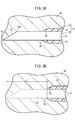
- FIG. 3A is an explanatory view showing a state in which the subcutaneous administration indwelling needle of FIG. 1 is punctured into the subcutaneous tissue
- FIG. 3B is an explanatory view showing a state in which the inner needle is pulled out from the subcutaneous administration indwelling needle of FIG. .
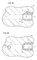
- FIG. 4A is an explanatory view showing a state in which the outer needle of the indwelling needle for subcutaneous administration of FIG. 1 is displaced toward the tip side
- FIG. 4A is an explanatory view showing a state in which the outer needle of the indwelling needle for subcutaneous administration of FIG. 1 is displaced toward the tip side
- FIG. 4B is an explanatory view showing a state in which the outer needle of the indwelling needle for subcutaneous administration of FIG. 1 is displaced. It is explanatory drawing which shows the state. It is explanatory drawing of the experimental example of 1st Embodiment, and shows the example of puncturing the subcutaneous tissue of a pig with the indwelling needle for subcutaneous administration of 24G, and ejecting a simulated thrombus.
- FIG. 6A is a graph showing the pressure required for discharging the simulated thrombus in the indwelling needle for subcutaneous administration of Reference Example 1 without puncturing the subcutaneous tissue
- FIG. 6B is the indwelling needle for subcutaneous administration according to Example 1.
- FIG. 8A is a graph showing the measurement results of the simulated thrombus length and the administration pressure in Comparative Example 2
- FIG. 8B is a graph showing the measurement results of the simulated thrombus length and the administration pressure in Comparative Example 3.
- FIG. 9A is a graph showing the measurement results of the simulated thrombus length and the administration pressure in Example 2, and FIG.
- FIG. 9B is a graph showing the measurement results of the simulated thrombus length and the administration pressure in Example 3.
- FIG. 10A is a graph showing the measurement results of the simulated thrombus length and the administration pressure in Example 4, and FIG. 10B shows the measurement results of the simulated thrombus length and the administration pressure in Reference Example 2 (in the atmosphere). It is a graph. It is a table which shows the maximum discharge power of Comparative Examples 2, 3 and Examples 2 to 4 and Reference Example 2 with respect to the simulated thrombus having a length of 10 mm or less.
- FIG. 10A is a graph showing the measurement results of the simulated thrombus length and the administration pressure in Example 4
- FIG. 10B shows the measurement results of the simulated thrombus length and the administration pressure in Reference Example 2 (in the atmosphere). It is a graph. It is a table which shows the maximum discharge power of Comparative Examples 2, 3 and Examples 2 to 4 and Reference Example 2 with respect to the simulated thrombus having a length of 10 mm
- FIG. 12A is a graph showing the transition of the discharge force of the indwelling needle for subcutaneous administration according to Comparative Example 4 in the subcutaneous tissue of the excised pig, with the stroke distance of the syringe on the horizontal axis and the discharge force on the vertical axis.
- FIG. 12B is a graph showing the transition of the discharge force of the indwelling needle for subcutaneous administration according to Comparative Example 4 in the subcutaneous tissue of a living pig.
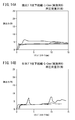
- FIG. 13A is a graph showing the transition of the discharge force of the indwelling needle for subcutaneous administration according to Example 5 in the subcutaneous tissue of the excised pig, with the stroke distance of the syringe on the horizontal axis and the discharge force on the vertical axis.
- FIG. 13B is a graph showing the transition of the discharge force of the indwelling needle for subcutaneous administration according to Example 5 in the subcutaneous tissue of a living pig.
- FIG. 14A is a graph showing the transition of the discharge force of the indwelling needle for subcutaneous administration according to Example 6 in the subcutaneous tissue of the excised pig, with the stroke distance of the syringe on the horizontal axis and the discharge force on the vertical axis.
- FIG. 14B is a graph showing the transition of the discharge force of the indwelling needle for subcutaneous administration according to Example 6 in the subcutaneous tissue of a living pig.
- FIG. 14A is a graph showing the transition of the discharge force of the indwelling needle for subcutaneous administration according to Example 6 in the subcutaneous tissue of the excised pig, with the stroke distance of the syringe on the horizontal axis and the discharge force on the vertical axis.
- FIG. 14B is a graph showing the transition of the discharge force of the indwelling needle
- FIG. 15A is a graph showing the transition of the discharge force of the indwelling needle for subcutaneous administration according to Example 7 in the subcutaneous tissue of the excised pig, with the stroke distance of the syringe on the horizontal axis and the discharge force on the vertical axis.
- FIG. 15B is a graph showing the transition of the discharge force of the indwelling needle for subcutaneous administration according to Example 7 in the subcutaneous tissue of a living pig.
- 16A and 16B are diagrams showing the maximum emission force distributions of Comparative Example 4 and Examples 5, 6 and 7.
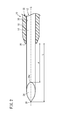
- the indwelling needle 10 for subcutaneous administration includes an inner needle 12 and an outer needle 22 (catheter). As shown in the figure, the indwelling needle 10 for subcutaneous administration is punctured into the subcutaneous tissue of a living body with the inner needle 12 attached to the outer needle 22. Then, the indwelling needle 10 for subcutaneous administration is used to puncture the subcutaneous tissue, pull out the inner needle 12, attach a drug solution administration device such as a syringe to the outer needle 22, and administer the drug solution subcutaneously to the living body. To.
- the outer needle 22 (catheter) includes a tubular outer needle body 18 and a hollow tubular outer needle hub 20 connected to the proximal end side of the outer needle body 18.
- the inner needle 12 has a wire-shaped inner needle main body 14 having a circular cross section, and a cylindrical inner needle hub 16 connected to a base end portion of the inner needle main body 14.
- the inner needle 12 is fitted into the hub insertion portion 32 inside the outer needle 22, and in this state, the blade surface 24 formed at the tip portion of the inner needle body 14 protrudes from the tip of the outer needle body 18. ing.
- the outer needle body 18 is made of, for example, a resin material, has flexibility and appropriate elasticity, and is formed so as to extend in the axial G direction.
- the outer needle body 18 reaches near the tip of the inner needle body 14 when the inner needle 12 is attached to the outer needle 22, and the tip of the inner needle body 14 is inserted into the subcutaneous tissue 90 by a predetermined length or more. Then, the tip 28 of the outer needle body 18 is also inserted into the subcutaneous tissue 90 in the vicinity of the inner needle body 14.
- the constituent material of the outer needle body 18 include various flexible resins such as ethylene-tetrafluoroethylene copolymer (ETFE), PTFE, polyurethane, and polyether nylon resin.
- the outer needle hub 20 is a resin member formed in a hollow tubular shape with both ends open in the axis G direction.
- the constituent material of the outer needle hub 20 include polyolefins such as polyethylene, polypropylene, and ethylene-vinyl acetate copolymer, polyvinyl chloride, polymethylmethacrylate, polycarbonate, polyamide, and polyester.
- the base end portion of the outer needle body 18 is connected and fixed to the tip end side of the outer needle hub 20.
- a hub insertion portion 32 having a cylindrical inner surface into which the inner needle hub 16 is inserted is provided on the proximal end side of the connection portion with the outer needle main body 18.
- the inner diameter of the hub insertion portion 32 increases continuously or stepwise from the tip end portion toward the base end portion side.
- the hub insertion portion 32 is formed with a fitting surface substantially parallel to the axis G direction.
- a blade surface 24 inclined with respect to the axis G direction is formed at the tip of the inner needle body 14.
- a material capable of forming the cutting edge sharply to the extent that a sufficient puncture force (penetration force) can be obtained and having a strength required for puncture is used. Specific examples thereof include stainless steel, aluminum alloys and copper alloys.
- the inner needle body 14 can be appropriately selected according to the size of the outer needle body 18. For example, when the outer needle body 18 is 14 G (outer diameter 2.11 mm, inner diameter 1.69 mm), the inner needle body 14 can be 16 G (outer diameter 1.65 mm).
- the outer needle body 18 can be about 27 G to 14 G (outer diameter 0.41 to 2.11 mm), and the inner needle body 14 can be about 30 G to 16 G (outer diameter 0.12 to 1.65 mm) accordingly. Can be.
- a sharp needle tip 26 is formed at the tip of the blade surface 24.
- the needle tip 26 of the inner needle body 14 projects by a predetermined protrusion distance L with respect to the tip 28 of the outer needle 22 in a state where the inner needle 12 is attached to the outer needle 22.
- the protrusion distance L is set to a length capable of forming a space having a sufficient length on the tip end side of the outer needle 22 in the subcutaneous tissue 90 after the inner needle 12 is pulled out.
- the protrusion distance L is preferably 2.5 mm or more.
- the protrusion distance L is preferably 9 mm or less.
- the living body has an epidermis, a dermis, a subcutaneous tissue, and a muscular layer in this order from the surface side, but the inner needle body 14 of the present embodiment is used by being punctured by the dermis and the subcutaneous tissue.
- Patients who are expected to use the indwelling needle 10 for subcutaneous administration of the present embodiment are, for example, children to adults around 12 years old, but the thickness of the dermis and the subcutaneous tissue varies depending on the age and gender. According to the document "Derraik, et al. PLOS ONE 2014, 9 (1)", it is reported that males have thinner dermis and subcutaneous tissue than females, and children are thinner. .. According to the same document, the average thickness of the dermis in the abdomen of a 12-year-old ( ⁇ 3.1-year-old) boy is 1.89 mm, and the average thickness of the subcutaneous tissue is 9.13 mm. There is.
- the protrusion distance L of the inner needle body 14 is set to 9 mm or less so as not to puncture the subcutaneous tissue even if the needle 10 is vertically punctured into the skin. ..
- the inner needle body 14 and the outer needle body 18 are punctured at 20 ° to 45 ° against the skin. For example, when puncturing the abdomen at 20 °, even a child needs a length of about 32 mm in order to puncture the muscular layer. Since the protrusion distance L of the inner needle body 14 of the present embodiment is sufficiently smaller than this value, it can be used with a margin.
- the indwelling needle 10 for subcutaneous administration can be used in a portion other than the abdomen.
- the indwelling needle 10 for subcutaneous administration of the present embodiment can also be used by puncturing it perpendicularly to the skin.
- the protrusion distance L between the needle tip 26 and the tip portion 28 of the outer needle 22 is the axial length of the blade surface 24 and the axial direction between the heel portion 24a of the blade surface 24 and the tip portion 28 of the outer needle body 18. Is the sum of the distance ⁇ .
- the axial length of the blade surface 24 is determined by the diameter of the inner needle body 14, and can be approximately 1 mm. In this case, in order to set the protrusion distance L to 3 mm or more, the distance ⁇ between the heel portion 24a of the blade surface 24 and the tip portion 28 of the outer needle body 18 may be set to 2 mm.
- the inner needle hub 16 is a resin member formed in a hollow tubular shape with both ends open in the axis G direction.
- Examples of the constituent material of the inner needle hub 16 include the same constituent materials as those of the outer needle hub 20 described above.
- the base end of the inner needle body 14 is connected and fixed to the tip of the inner needle hub 16.
- the tip 38 inserted into the hub insertion portion 32 of the outer needle hub 20 of the inner needle hub 16 extends substantially parallel to the axis G direction and has a fitting surface when the inner needle 12 is attached to the outer needle 22.
- a contact surface 36 that comes into contact with the surface 36 is formed.
- the inner needle 12 and the outer needle 22 are configured to be fixed to each other by the frictional force of the fitting portion.
- the indwelling needle 10 for subcutaneous administration of the present embodiment is basically configured as described above, and its action and effect will be described below.
- the inner needle 12 is attached to the outer needle 22.
- the inner needle 12 is attached by inserting the inner needle body 14 from the base end side of the outer needle hub 20.
- the inner needle body 14 is inserted through the outer needle hub 20 along the inner cavity 30 of the outer needle body 18, and finally, the inner needle hub 16 is inserted into the outer needle hub 20 and pushed in to hit both.
- the inner needle hub 16 stops and the inner needle 12 and the outer needle 22 are connected.
- the indwelling needle 10 for subcutaneous administration is assembled with the needle tip 26 of the inner needle body 14 protruding from the tip 28 of the outer needle body 18 by a protrusion distance L.
- the subcutaneous administration indwelling needle 10 In order to puncture the subcutaneous administration indwelling needle 10, first, a medical worker such as a doctor or the patient himself / herself grasps the subcutaneous administration indwelling needle 10 and punctures the patient's subcutaneous tissue 90, and then the subcutaneous administration indwelling needle 10 is punctured. 10 is gradually inserted toward the desired site. As a result, as shown in FIG. 3A, the subcutaneous administration indwelling needle 10 advances while the needle tip 26 of the subcutaneous administration indwelling needle 10 cuts open the subcutaneous tissue 90.
- the inner needle 12 is removed from the outer needle 22.
- the inner needle body 14 of the inner needle 12 protrudes from the outer needle 22 by a predetermined length L.
- a gap 92 (crevice) having a sufficient length remains in the subcutaneous tissue 90 on the distal end side of the distal end 28 of the outer needle 22 by removing the inner needle 12.
- the outer needle 22 of the portion exposed from the patient's skin is fixed to the patient's skin, and a syringe filled with the drug solution is connected to the outer needle hub 20 to perform subcutaneous administration of the drug solution.
- the displacement when fixing the outer needle 22 and the displacement when connecting the syringe are transmitted to the tip 28 of the outer needle body 18, and the tip 28 of the outer needle body 18 is pushed toward the tip side.
- the indwelling needle 10 for subcutaneous administration of the present embodiment since a gap 92 having a sufficient length is formed on the tip end side of the outer needle body 18, the displacement of the outer needle body 18 can be absorbed by the gap 92.
- Example 1 In Reference Example 1, an outer needle 22 (thickness 24 G) of the indwelling needle 10 for subcutaneous administration was prepared, and a simulated thrombus 98 having an axial length of about 11 mm was formed in the lumen 30 near the tip portion 28 thereof. Then, a syringe containing a physiological saline solution was connected to the outer needle hub 20 of the outer needle 22, and the pressure required for discharging the simulated thrombus 98 from the outer needle 22 was measured. The measurement of Reference Example 1 was performed 5 times.
- Example 1 a simulated thrombus 98 having a length of about 11 mm in the axial direction is provided in the lumen 30 of the outer needle 22 of the indwelling needle 10 for subcutaneous administration in FIG. 1, and as shown in FIG. 5, the subcutaneous tissue 100 of the pig is provided.
- the inner needle 12 was pulled out to form a gap 92.
- the protrusion distance L of the needle tip 26 of the inner needle 12 from the outer needle 22 was set to 4 mm. Further, the outer needle 22 used had a thickness of 24 G.
- Example 1 As described above was performed 5 times.
- Comparative Example 1 using the same outer needle 22 as in Example 1, the outer needle 22 was placed in the subcutaneous tissue 100 of the pig as shown in FIG. 5, and the pressure required for discharging the simulated thrombus 98 was measured.
- the protrusion distance L of the inner needle 12 when the outer needle 22 was punctured into the subcutaneous tissue 100 was set to 0 mm. That is, in Comparative Example 1, the pressure (input load to the syringe) required for discharging the simulated thrombus 98 was measured under the condition that the gap 92 was not formed on the tip side of the outer needle 22. In Comparative Example 1, the measurement was performed 5 times.
- the pressure of the liquid supplied from the syringe increases as the stroke of the syringe increases, and the simulated thrombus 98 is discharged from the outer needle 22 at a predetermined pressure to decrease the pressure. ..
- the pressure required for discharging the simulated thrombus 98 is obtained as the maximum pressure immediately before the pressure decreases with respect to the increase in the stroke.
- the simulated thrombus 98 is discharged from the outer needle 22 with an input load of about 10 N at the maximum.
- Example 1 of FIG. 6B As shown in the result of Example 1 of FIG. 6B, when the needle tip 26 of the inner needle 12 is projected by 4 mm, the simulated thrombus 98 may be discharged from the outer needle 22 with an input load of about 12 N at the maximum. It could be confirmed. This value is close to the result of Reference Example 1 outside the skin, and according to Example 1 of the present embodiment, it can be seen that the simulated thrombus 98 can be discharged with the same pressure as outside the skin.
- the thrombus can be discharged from the outer needle 22 without increasing the discharge pressure, and that the drug solution can be reliably subcutaneously administered.
- Example 2 In Experimental Example 2, the drainage power of the simulated thrombus 98 was evaluated. That is, a simulated thrombus 98 made of gelatin of various lengths is provided in the outer needle 22 of the indwelling needle 10 for subcutaneous administration, and is placed in the subcutaneous tissue 100 of the removed pig (the subcutaneous tissue of the removed pig), and its drainage force. was measured with an autograph (automatic load measuring device).
- the outer needle 22 used had a thickness of 24 G.
- the protrusion distance L of the inner needle 12 with respect to the outer needle 22 was set to 0 mm (Comparative Example 2), 2 mm (Comparative Example 3), 3 mm (Example 2), 5 mm (Example 3), and 8 mm (Example 4).
- the discharge force when the simulated thrombus 98 was discharged in the atmosphere without puncturing the subcutaneous tissue 100 with the outer needle 22 was measured as Reference Example 2.
- Examples 2, 3 and 4 are about the same as 15N, which is the maximum value of the discharge force of Reference Example 2 for discharging the simulated thrombus 98 in the atmosphere shown in FIG. 10B, and the simulated thrombus 98 is discharged. It can be seen that it is effective to set the protrusion distance L of the inner needle 12 to 3 mm or more.
- a physiological saline solution was placed in the subcutaneous tissue of the removed pig and the subcutaneous tissue of the living pig, respectively, and a pressing load of 20 N was applied to the outer needle 22 and the skin around it with a push-pull gauge.
- the excretion power (administration pressure) of the pig was measured by an autograph.
- the thickness of the outer needle 22 was 24 G, and the insertion angle of the outer needle 22 was 20 °.
- the pressing load of 20 N is assumed to be a load applied to the outer needle 22 placed in the abdomen when an adult with a weight of 60 kg lies down.
- Comparative Example 4 in which the protrusion distance L of the inner needle 12 when the indwelling needle 10 for subcutaneous administration was punctured into the subcutaneous tissue was 1.8 mm, and Example 5 in which the protrusion distance L was 2.5 mm.
- the measurement was performed on Example 6 in which the protrusion distance L was 3 mm and Example 7 in which the protrusion distance L was 5 mm.
- the subcutaneous tissue of the removed pig and the subcutaneous tissue of the living pig were measured 5 times each.
- the maximum excretion power shows a large value of 21N in the subcutaneous tissue of the excised pig and 24N in the subcutaneous tissue of the living pig.
- the maximum drainage power of Example 5 was 7N in the subcutaneous tissue of the removed pig and 6N in the subcutaneous tissue of the living pig
- the maximum draining power of Example 6 was 6N in the subcutaneous tissue of the removed pig and 8N in the subcutaneous tissue of the living pig. It turns out that it becomes a small value. Further, it was confirmed that the maximum excretion power of Example 7 was 5N in the subcutaneous tissue of the excised pig and 4N in the subcutaneous tissue of the living pig, which were even smaller than those of Examples 5 and 6.
- Examples 5, 6 and 7 are smaller than Comparative Example 4. From this result, it can be seen that setting the protrusion distance L of the inner needle 12 of the indwelling needle 10 for subcutaneous administration to 2.5 mm or more is effective in stabilizing the administration pressure in an environment where a load acts.
- the indwelling needle 10 for subcutaneous administration of the present embodiment has the following effects.
- the indwelling needle 10 for subcutaneous administration includes an inner needle 12 having an inner needle body 14 having a sharp needle tip 26 formed at the tip thereof and an inner needle hub 16 provided on the proximal end side of the inner needle body 14.
- An outer needle hub 18 having an inner cavity 30 through which the inner needle 12 is inserted, and an outer needle hub provided on the base end side of the outer needle body 18 and having a hub insertion portion 32 into which the inner needle hub 16 is mounted.
- a gap 92 having a sufficient length can be formed on the tip end side of the outer needle 22 in the subcutaneous tissue 90 after the inner needle 12 is pulled out.
- a gap 92 By forming such a gap 92, it is possible to prevent breakage (kink) or blockage of the outer needle 22 and reliably administer the drug solution.
- the protrusion distance L of the needle tip 26 of the inner needle 12 with respect to the tip 28 of the outer needle 22 can be set to 5 mm or less. With this configuration, it is possible to prevent the needle tip 26 from damaging an unnecessary portion.
- the inner needle 12 has a blade surface 24 inclined with respect to the axial direction, so that the heel portion 24a at the base end of the blade surface 24 projects toward the tip side of the outer needle 22. It may be configured. As a result, a desired protrusion distance L can be secured without changing the angle of the blade surface 24.
- the heel portion 24a may be configured to protrude 1 mm or more toward the tip end side of the tip portion 28 of the outer needle 22. Since the indwelling needle 10 for subcutaneous administration is intended for subcutaneous puncture, it is not necessary to consider damage to blood vessels, and the heel portion 24a protrudes 1 mm or more toward the tip side of the tip portion 28 of the outer needle 22. There is no problem.
- the axial length of the blade surface 24 may be set to 1 mm or more instead of the protruding distance L of the heel portion 24a or by adjusting the protruding distance L of the heel portion 24a.
- the protrusion distance L may be adjusted not only by the position of the heel portion 24a but also by the axial length of the blade surface 24.
- the indwelling needle for subcutaneous administration has been described with reference to suitable embodiments, but the indwelling needle for subcutaneous administration is not limited to the above-described embodiment, and various modifications are made without departing from the spirit of the present invention. Needless to say, is possible.
Landscapes
- Health & Medical Sciences (AREA)
- Life Sciences & Earth Sciences (AREA)
- Animal Behavior & Ethology (AREA)
- General Health & Medical Sciences (AREA)
- Biomedical Technology (AREA)
- Heart & Thoracic Surgery (AREA)
- Hematology (AREA)
- Engineering & Computer Science (AREA)
- Veterinary Medicine (AREA)
- Anesthesiology (AREA)
- Public Health (AREA)
- Vascular Medicine (AREA)
- Biophysics (AREA)
- Pulmonology (AREA)
- Infusion, Injection, And Reservoir Apparatuses (AREA)
- Media Introduction/Drainage Providing Device (AREA)
Abstract
皮下組織に留置して薬液を皮下に投与するための皮下投与用留置針(10)であって、先端部に鋭利な針先(26)が形成された内針本体(14)と、内針本体(14)の基端側に設けられた内針ハブ(16)と、を有する内針(12)と、内針(12)が挿通する内腔(30)を有する外針本体(18)と、外針本体(18)の基端側に設けられるとともに、内針ハブ(16)が装着されるハブ挿入部(32)が形成された外針ハブ(20)と、を有する外針(22)と、を備え、内針ハブ(16)を外針ハブ(20)内に装着した状態において、内針(12)の針先(26)が外針(22)の先端部(28)から軸方向に2.5~9mm突出している、皮下投与用留置針(10)が提供される。
Description
本発明は、生体内に留置して薬液を投与するための皮下投与用留置針に関する。
薬剤を生体内に投与する場合に、鋭利な針先が形成された内針と、その内針を覆うようにして形成された筒状の外針(カテーテル)とで構成された二重構造の留置針(カテーテル組立体)が用いられている。外針の先端は鈍に形成されており、鋭利な内針が外針の先端から突出した状態で生体内に導入される。生体内に導入した後は、内針を引き抜くことで外針が生体内に留置される。そして、外針の内腔を介して、生体内に薬液の投与が行われる。留置針は、主に血管(静脈等)へ穿刺されて使用されるが、皮下組織に留置する場合もある。
例えば、特開2016-127872号公報には、薬液を皮下に投与するために皮下に留置する留置針に関し、穿刺部を内針と外針との二重構造とした留置針を開示する。
ところが、外針を皮下組織に留置する場合には、外針の折損や閉塞が生じやすいという問題がある。すなわち、外針を皮膚に固定する際の振動で外針が先端側に前進してしまう場合や、生体が動くことによって外針が前進してしまう場合がある。このような場合には、外針が皮下組織に突き当たってしまって折損(キンク)が生じるおそれがある。また、外針の先端側が壁状の皮下組織によって閉塞されてしまい、内腔を通じた薬液の投与が滞り、投与圧が増大してしまうおそれがある。
また、留置針を生体内に留置したまま数時間程度の間隔で間欠的に薬液を投与する場合には、薬液が流れていない間に、外針の内腔にたんぱく質や細胞等が集まり、血栓状の塊が生じることがある。このような場合には、血栓を外針の内腔から排出することができず、留置針が閉塞されてしまうという問題がある。
したがって、皮下組織へ留置した場合でも、キンクや閉塞を防ぐことができる皮下投与用留置針が求められる。
以下の開示の一観点は、皮下組織に留置して薬液を皮下に投与するための皮下投与用留置針であって、先端部に鋭利な針先が形成された内針本体と、前記内針本体の基端側に設けられた内針ハブと、を有する内針と、前記内針が挿通する内腔を有する外針本体と、前記外針本体の基端側に設けられるとともに、前記内針ハブが装着されるハブ挿入部が形成された外針ハブと、を有する外針と、を備え、前記内針ハブを前記外針ハブ内に装着した状態において、前記内針の前記針先が前記外針の先端部から軸方向に2.5~9mm突出している、皮下投与用留置針にある。
上記観点の皮下投与用留置針によれば、皮下組織へ留置した場合でも、キンクや閉塞を防ぐことができる。
以下、皮下投与用留置針について好適な実施形態を挙げ、添付の図面を参照して詳細に説明する。
本実施形態に係る皮下投与用留置針10は、図1に示すように、内針12と外針22(カテーテル)とを備えている。皮下投与用留置針10は、図示のように、内針12を外針22に装着した状態で生体の皮下組織に穿刺される。そして、皮下投与用留置針10は、皮下組織に穿刺した後、内針12を引き抜き、外針22にシリンジ等の薬液投与デバイスを装着して、生体の皮下に薬液を投与するのに使用される。
外針22(カテーテル)は、チューブ状の外針本体18と、外針本体18の基端側部に接続された中空筒状の外針ハブ20とを備える。内針12は、断面が円形のワイヤ状の内針本体14と、内針本体14の基端部に接続された円筒状の内針ハブ16とを有する。内針12は、外針22の内部のハブ挿入部32に嵌挿されており、この状態において、内針本体14の先端部に形成された刃面24が、外針本体18の先端より突出している。
外針本体18は、例えば、樹脂材料等からなり、柔軟且つ適度な弾性を有し、軸G方向に長尺に延びて形成されている。外針本体18は、内針12を外針22に装着した状態のとき、内針本体14の先端近傍まで達しており、内針本体14の先端部が皮下組織90内に所定長さ以上挿入されると、外針本体18の先端部28も内針本体14の近傍の皮下組織90内に挿入されることとなる。外針本体18の構成材料としては、例えば、エチレン-テトラフルオロエチレン共重合体(ETFE)、PTFE、ポリウレタン、ポリエーテルナイロン樹脂等の各種柔軟性樹脂が挙げられる。
外針ハブ20は、軸G方向の両端が開口した中空筒状に形成された樹脂製の部材である。外針ハブ20の構成材料としては、例えば、ポリエチレン、ポリプロピレン、エチレン-酢酸ビニル共重合体等のポリオレフィン、ポリ塩化ビニル、ポリメチルメタクリレート、ポリカーボネート、ポリアミド、ポリエステル等が挙げられる。
外針ハブ20の先端側には、外針本体18の基端部が接続されて固定されている。外針ハブ20において、外針本体18との接続部よりも基端側には、内針ハブ16が挿入される円筒内面を有するハブ挿入部32が設けられている。ハブ挿入部32の内径は、先端部から基端部側に向かって連続的又は段階的に大きくなっている。ハブ挿入部32には、軸G方向と略平行な嵌合面が形成されている。
図2に示すように、内針本体14の先端部には、軸G方向に対して傾斜した刃面24が形成されている。内針本体14の構成材料としては、十分な穿刺力(貫通力)が得られる程度に刃先を鋭利に形成でき、且つ、穿刺に必要な強度を持つ材料が使用される。具体的には、例えば、ステンレス鋼、アルミニウム合金、銅合金等が挙げられる。内針本体14は、外針本体18のサイズに応じて適宜選択できる。例えば、外針本体18が14G(外径2.11mm、内径1.69mm)の場合には、内針本体14は16G(外径1.65mm)とすることができる。外針本体18は、27G~14G(外径0.41~2.11mm)程度とすることができ、それに応じて内針本体14は30G~16G(外径0.12~1.65mm)程度とすることができる。刃面24の先端には、鋭利な針先26が形成されている。
内針本体14の針先26は、内針12を外針22に装着した状態において、外針22の先端部28に対して、所定の突出距離Lだけ突出する。この突出距離Lは、内針12を引き抜いた後の皮下組織90に、外針22の先端側に十分な長さの空間を形成可能な長さに設定される。例えば、突出距離Lは2.5mm以上とすることが好ましい。また、突出距離Lが長すぎると、皮下組織90の奥の筋層を穿刺してしまう等して侵襲が増大するため、突出距離Lは9mm以下とすることが好ましい。
すなわち、生体は表面側から順に表皮、真皮、皮下組織、筋層を備えているが、本実施形態の内針本体14は、真皮及び皮下組織に穿刺されて使用される。本実施形態の皮下投与用留置針10の使用が想定される患者としては、例えば12歳前後の子供から成人であるが、真皮及び皮下組織の厚さは、年齢性別によって異なる。文献“Derraik, et al.PLOS ONE 2014, 9(1)”によれば、男性の方が女性よりも真皮及び皮下組織の厚さが薄く、さらに、子供の方が薄いという報告がなされている。同文献では、12歳(±3.1歳)の男子の腹部における真皮の厚さの平均値は1.89mmであり、同じく皮下組織の厚さの平均値は9.13mmであるとされている。
そこで、本実施形態の皮下投与用留置針10は、仮に皮膚に垂直に穿刺した場合であっても、皮下組織を刺し貫かないように、内針本体14の突出距離Lを、9mm以下としている。実際には、内針本体14及び外針本体18は、皮膚に対して20°~45°で穿刺される。例えば、腹部に20°で穿刺する場合には、筋層にまで穿刺するためには子供であっても32mm程度の長さが必要である。本実施形態の内針本体14の突出距離Lはこの値よりも十分に小さいため、余裕をもって使用することができる。また、斜めに穿刺する場合には、皮下投与用留置針10を腹部以外の部位にも使用することができる。また、本実施形態の皮下投与用留置針10は、皮膚に対して垂直に穿刺して使用することもできる。
なお、針先26と外針22の先端部28との突出距離Lは、刃面24の軸方向の長さと、刃面24のヒール部24aと外針本体18の先端部28との軸方向の距離αとの和である。刃面24の軸方向の長さは、内針本体14の直径によって決まり、概ね1mm程度とすることができる。この場合、突出距離Lを3mm以上とするには、刃面24のヒール部24aと外針本体18の先端部28との距離αを2mmとすればよい。
図1に示すように、内針本体14の基端部は、内針ハブ16の先端部に結合されて保持されている。内針ハブ16は、軸G方向の両端が開口した中空筒状に形成された樹脂製の部材である。内針ハブ16の構成材料としては、上記した外針ハブ20と同様の構成材料が挙げられる。
内針ハブ16の先端部には、内針本体14の基端部が接続されて固定されている。内針ハブ16の外針ハブ20のハブ挿入部32に挿入される先端部38には、軸G方向に略平行に延在し、内針12を外針22に装着したときに嵌合面と当接する当接面36が形成されている。内針12と外針22とは、嵌合部分の摩擦力により相互に固定されるように構成されている。
本実施形態の皮下投与用留置針10は、基本的には以上のように構成されるものであり、以下、その作用及び効果について説明する。
まず、内針12を外針22に装着する。内針12は、外針ハブ20の基端部側から内針本体14を挿入して装着する。内針本体14を、外針ハブ20を介して外針本体18の内腔30に沿って挿通させてゆき、最後に、外針ハブ20に内針ハブ16を挿入して押込み、両者を当接させることで内針ハブ16が停止して内針12と外針22とが接続される。これにより、内針本体14の針先26が外針本体18の先端部28から突出距離Lだけ突出した状態で皮下投与用留置針10が組み上がる。
皮下投与用留置針10を穿刺するには、まず、医師等の医療従事者又は患者本人が皮下投与用留置針10を把持して患者の皮下組織90に向かって穿刺し、皮下投与用留置針10を所望部位に向けて徐々に挿入してゆく。これにより、図3Aに示すように、皮下投与用留置針10の針先26が皮下組織90を切り開きながら、皮下投与用留置針10が進む。
その後、図3Bに示すように、外針22から内針12を抜去する。本実施形態の皮下投与用留置針10によれば、内針12の内針本体14が、外針22から所定の長さLだけ突出している。これにより、外針22の先端部28の先端側の皮下組織90内に、内針12の抜去によって十分な長さの隙間92(裂け目)が残る。
その後、患者の皮膚から露出している部分の外針22を患者の皮膚に固定するとともに、外針ハブ20に薬液が充填されたシリンジを接続して、薬液の皮下投与を行う。図4Aに示すように、外針22を固定する際の変位や、シリンジを接続する際の変位が外針本体18の先端部28に伝わり、外針本体18の先端部28が先端側に押し込まれる場合がある。これに対し、本実施形態の皮下投与用留置針10では、外針本体18の先端側に十分な長さの隙間92が形成されるため、外針本体18の変位を隙間92で吸収できる。これにより、外針本体18の折損(キンク)を防ぐことができる。また、外針本体18の先端に隙間92が形成されているため、皮下組織90によって外針22の内腔30が塞がれ難くなっているため、確実に薬液を注入できる。
また、外針22を皮下組織90に留置しておくと、生体反応により、図4Bに示すように、外針本体18の内腔30内に生体内の血液やたんぱく質等が入り込み、これらが血栓状の析出物94を生み出す場合がある。このような場合であっても、本実施形態の皮下投与用留置針10によれば、外針本体18の先端側に十分な長さの隙間92が形成されるため、その隙間92内に析出物94をスムーズに排出させることができる。これにより、薬液の注入圧力を高めることなく析出物94が排出でき、生体の皮下へ、薬液の投与を確実に行うことができる。
以下、本実施形態の皮下投与用留置針10の効果を確認するために実験を行った結果について説明する。
(実験例1)
参考例1では、皮下投与用留置針10の外針22(太さ24G)を用意し、その先端部28付近の内腔30に軸方向の長さが11mm程度の模擬血栓98を形成した。その後、外針22の外針ハブ20に生理食塩水を収容したシリンジを接続して、外針22から模擬血栓98の吐出に要する圧を測定した。参考例1の測定は5回行った。
参考例1では、皮下投与用留置針10の外針22(太さ24G)を用意し、その先端部28付近の内腔30に軸方向の長さが11mm程度の模擬血栓98を形成した。その後、外針22の外針ハブ20に生理食塩水を収容したシリンジを接続して、外針22から模擬血栓98の吐出に要する圧を測定した。参考例1の測定は5回行った。
実施例1では、図1の皮下投与用留置針10の外針22の内腔30に軸方向に長さ11mm程度の模擬血栓98を設け、図5に示すように、ブタの皮下組織100に対して留置した後、内針12を引き抜いて隙間92を形成した。なお、内針12の針先26の外針22からの突出距離Lは4mmとした。また、外針22は24Gの太さのものを用いた。
その後、外針ハブ20に接続したシリンジから生理食塩水を注入して、どの程度の圧力(シリンジへの入力荷重)で模擬血栓98が外針22から排出されるかを測定した。以上のような実施例1の測定は5回行った。
比較例1では、実施例1と同様の外針22を用い、図5に示すようにブタの皮下組織100に外針22を留置し、模擬血栓98の排出に要する圧力の測定を行った。ただし、比較例1においては、皮下組織100に外針22を穿刺する際の内針12の突出距離Lは0mmとした。すなわち、比較例1では、外針22の先端側に隙間92を形成しない条件で、模擬血栓98の排出に要する圧力(シリンジへの入力荷重)を測定した。比較例1においても、測定を5回行った。
図6Aの参考例1の結果に示すように、シリンジから供給される液体の圧力はシリンジのストロークの増大とともに上昇し、所定の圧力で模擬血栓98が外針22から排出されて圧力が低下する。ストロークの増加に対して圧力が低下する直前の最大圧力として、模擬血栓98の吐出に要する圧力が求まる。図示のように、参考例1では、最大でも10N程度の入力荷重で模擬血栓98が外針22から排出されることがわかる。
図6Bの実施例1の結果に示すように、内針12の針先26を4mm突出させた場合には、最大でも12N程度の入力荷重で模擬血栓98が外針22から排出されることが確認できた。この値は、皮膚外における参考例1の結果に近いものであり、本実施形態の実施例1によれば、皮膚外と同程度の圧力で、模擬血栓98を排出できることがわかる。
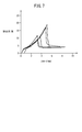
一方、図7の比較例1の結果では、模擬血栓98の排出に20N近い入力荷重が必要となる場合があり、皮下投与の際の薬液の吐出圧力が高くなってしまう結果となった。
上記のように、吐出圧力を高くすることなく、外針22から血栓を排出でき、確実に薬液の皮下投与を行えることが確認できた。
(実験例2)
実験例2では、模擬血栓98の排出力の評価を行った。すなわち、皮下投与用留置針10の外針22内に様々な長さのゼラチンよりなる模擬血栓98を設けて、摘出したブタの皮下組織100(摘出ブタ皮下組織)に留置して、その排出力をオートグラフ(自動荷重測定装置)で測定した。外針22は太さが24Gのものを用いた。外針22に対する内針12の突出距離Lは、0mm(比較例2)、2mm(比較例3)、3mm(実施例2)、5mm(実施例3)、8mm(実施例4)とした。また、外針22を皮下組織100に穿刺せずに、大気中で模擬血栓98を吐出させる際の排出力を参考例2として測定した。
実験例2では、模擬血栓98の排出力の評価を行った。すなわち、皮下投与用留置針10の外針22内に様々な長さのゼラチンよりなる模擬血栓98を設けて、摘出したブタの皮下組織100(摘出ブタ皮下組織)に留置して、その排出力をオートグラフ(自動荷重測定装置)で測定した。外針22は太さが24Gのものを用いた。外針22に対する内針12の突出距離Lは、0mm(比較例2)、2mm(比較例3)、3mm(実施例2)、5mm(実施例3)、8mm(実施例4)とした。また、外針22を皮下組織100に穿刺せずに、大気中で模擬血栓98を吐出させる際の排出力を参考例2として測定した。
図8A及び図8Bに示すように、比較例2(L=0mm)及び比較例3(L=2mm)の結果からは、模擬血栓98の排出力のばらつきが大きく、大きな排出力が必要となる場合があることがわかる。実用上重要な模擬血栓98の長さが10mm以下の範囲に着目すると、図11に示すように、比較例2では最大で40N以上の大きな排出力が必要であり、比較例3でも最大で25N程度の大きな排出力が必要となる場合がある。このように、比較例2、3では、模擬血栓98の排出の際に大きな投与圧が発生してしまう場合がある。
これに対し、図9A~図10Aに示すように、実施例2、3、4の結果では、排出力のばらつきが小さくなり、注入圧が安定化されることがわかる。模擬血栓98の長さが10mm以下の範囲に着目すると、図11に示すように、排出力の最大値は、実施例2(L=3mm)で11N程度、実施例3(L=5mm)で16N程度、実施例4(L=8mm)で12N程度と、排出力の最大値が比較例2、3に比べて抑制されることがわかる。これらの実施例2、3、4の結果は、図10Bに示す大気中で模擬血栓98を排出する参考例2の排出力の最大値である15Nと同程度であり、模擬血栓98の排出に当たっては、内針12の突出距離Lを3mm以上とすることが有効であることがわかる。
(実験例3)
ところで、皮下投与用留置針10を患者の皮下組織に留置して使用する場合には、患者が寝返りを打つ等して、皮下投与用留置針10の外針22に押圧荷重が作用することが想定される。このような押圧荷重が作用すると、外針22の先端の位置が変化して、投与圧が変化する可能性がある。そこで、本実験例では、皮下組織に留置した外針22に押付荷重を付与した場合の投与圧(排出力)の評価を行った。
ところで、皮下投与用留置針10を患者の皮下組織に留置して使用する場合には、患者が寝返りを打つ等して、皮下投与用留置針10の外針22に押圧荷重が作用することが想定される。このような押圧荷重が作用すると、外針22の先端の位置が変化して、投与圧が変化する可能性がある。そこで、本実験例では、皮下組織に留置した外針22に押付荷重を付与した場合の投与圧(排出力)の評価を行った。
本実験例においては、摘出ブタ皮下組織及び生体ブタ皮下組織内に、それぞれ外針22を留置してプッシュプルゲージで押圧荷重20Nを外針22及びその周辺の皮膚に付与しながら、生理食塩水の排出力(投与圧)をオートグラフで測定した。外針22の太さは24Gであり、外針22の刺入角度は20°とした。ここで、20Nの押圧荷重は、体重60kgの成人が横たわった際に腹部に留置した外針22に加わる荷重を想定している。
本実験例では、皮下投与用留置針10を皮下組織に穿刺する際の内針12の突出距離Lを1.8mmとした比較例4と、突出距離Lを2.5mmとした実施例5と、突出距離Lを3mmとした実施例6と、突出距離Lを5mmとした実施例7について測定を行った。また、本実験例では、摘出したブタの皮下組織と、生体のブタの皮下組織とについて、それぞれ5回測定を行った。
図12A及び図12Bに示すように、比較例4(L=1.8mm)では、摘出ブタ皮下組織及び生体ブタ皮下組織ともに、排出力のばらつきが大きく、最大排出力が20N以上の大きな値となる場合があることが判明した。
図13A及び図13Bに示すように、実施例5(L=2.5mm)では、摘出ブタ皮下組織及び生体ブタ皮下組織ともに、排出力のばらつきの範囲が比較例4よりも小さくなり、排出力も小さくなることがわかる。
また、図14A及び図14Bに示すように、実施例6(L=3mm)では、摘出ブタ皮下組織及び生体ブタ皮下組織ともに、排出力のばらつきの範囲が比較例4よりも小さくなり、排出力も小さくなることがわかる。
さらに、図15A及び図15Bに示すように、実施例7(L=5mm)では、摘出ブタ皮下組織及び生体ブタ皮下組織ともに、排出力のばらつきの範囲が比較例4よりも小さくなり、排出力も小さくなることがわかる。
図16A及び図16Bに示すように、最大排出力に着目すると、比較例4の場合には、最大排出力が摘出ブタ皮下組織で21N、生体ブタ皮下組織で24Nと大きな値を示す。これに対し、実施例5の最大排出力は、摘出ブタ皮下組織で7N、生体ブタ皮下組織で6N、実施例6の最大排出力は、摘出ブタ皮下組織で6N、生体ブタ皮下組織で8Nと小さな値になることがわかる。また、実施例7の最大排出力は、摘出ブタ皮下組織で5Nであり、生体ブタ皮下組織で4Nであり、実施例5、6よりもさらに小さな値となることが確認できた。
また、最大排出力のばらつきに関しては、実施例5、6、7は、比較例4よりも小さくなっている。この結果から、荷重が作用する環境下において、皮下投与用留置針10の内針12の突出距離Lを2.5mm以上とすることが、投与圧の安定化に効果的であることがわかる。
本実施形態の皮下投与用留置針10は以下の効果を奏する。
皮下投与用留置針10は、先端部に鋭利な針先26が形成された内針本体14と、内針本体14の基端側に設けられた内針ハブ16と、を有する内針12と、内針12が挿通する内腔30を有する外針本体18と、外針本体18の基端側に設けられるとともに、内針ハブ16が装着されるハブ挿入部32が形成された外針ハブ20と、を有する外針22と、を備え、内針ハブ16を外針ハブ20内に装着した状態において、内針12の針先26が外針22の先端部28から軸方向に2.5~9mm突出している。これにより、内針12を引き抜いた後の皮下組織90に、外針22の先端側に十分な長さの隙間92を形成することができる。このような隙間92が形成されることにより、外針22の折損(キンク)や閉塞を防いで確実に薬液の投与を行うことができる。
皮下投与用留置針10において、内針12の針先26の外針22の先端部28に対する突出距離Lを5mm以下とすることができる。この構成により、針先26により不要な部分に損傷を与えるのを防ぐことができる。
皮下投与用留置針10において、内針12は軸方向に対して傾斜した刃面24を有し、刃面24の基端のヒール部24aが外針22よりも先端側に突出しているように構成してもよい。これにより、刃面24の角度を変えることなく、所望の突出距離Lを確保することができる。この場合において、ヒール部24aが外針22の先端部28よりも1mm以上先端側に突出するように構成してもよい。皮下投与用留置針10は、皮下への穿刺を目的としているため、血管への損傷を考慮する必要がなく、ヒール部24aが外針22の先端部28よりも1mm以上先端側に突出していても問題はない。
皮下投与用留置針10において、ヒール部24aの突出距離Lに代えて、若しくはヒール部24aの突出距離Lの調整とともに、刃面24の軸方向の長さを1mm以上としてもよい。突出距離Lの調整は、ヒール部24aの位置だけではなく、刃面24の軸方向の長さで調整してもよい。
上記において、皮下投与用留置針について好適な実施形態を挙げて説明したが、皮下投与用留置針は前記実施形態に限定されるものではなく、本発明の趣旨を逸脱しない範囲において、種々の改変が可能なことは言うまでもない。
Claims (5)
- 皮下組織に留置して薬液を皮下に投与するための皮下投与用留置針であって、
先端部に鋭利な針先が形成された内針本体と、前記内針本体の基端側に設けられた内針ハブと、を有する内針と、
前記内針が挿通する内腔を有する外針本体と、前記外針本体の基端側に設けられるとともに、前記内針ハブが装着されるハブ挿入部が形成された外針ハブと、を有する外針と、を備え、
前記内針ハブを前記外針ハブ内に装着した状態において、前記内針の前記針先が前記外針の先端部から軸方向に2.5~9mm突出している、皮下投与用留置針。 - 請求項1記載の皮下投与用留置針であって、前記内針の前記針先の前記外針の先端部に対する突出距離が5mm以下である、皮下投与用留置針。
- 請求項1又は2記載の皮下投与用留置針であって、前記内針は軸方向に対して傾斜した刃面を有し、前記刃面の基端のヒール部が前記外針よりも先端側に突出している、皮下投与用留置針。
- 請求項3記載の皮下投与用留置針であって、前記ヒール部が前記外針の先端部よりも1mm以上先端側に突出している、皮下投与用留置針。
- 請求項3又は4記載の皮下投与用留置針であって、前記刃面の軸方向の長さが1mm以上である皮下投与用留置針。
Priority Applications (4)
| Application Number | Priority Date | Filing Date | Title |
|---|---|---|---|
| JP2021508268A JP7390360B2 (ja) | 2019-03-27 | 2020-02-19 | 皮下投与用留置針 |
| EP20776404.4A EP3919100A4 (en) | 2019-03-27 | 2020-02-19 | Indwelling subcutaneous administration needle |
| CN202080013095.4A CN113423446A (zh) | 2019-03-27 | 2020-02-19 | 皮下给药用留置针 |
| US17/484,438 US20220008653A1 (en) | 2019-03-27 | 2021-09-24 | Indwelling needle for subcutaneous administration |
Applications Claiming Priority (2)
| Application Number | Priority Date | Filing Date | Title |
|---|---|---|---|
| JP2019-060414 | 2019-03-27 | ||
| JP2019060414 | 2019-03-27 |
Related Child Applications (1)
| Application Number | Title | Priority Date | Filing Date |
|---|---|---|---|
| US17/484,438 Continuation US20220008653A1 (en) | 2019-03-27 | 2021-09-24 | Indwelling needle for subcutaneous administration |
Publications (1)
| Publication Number | Publication Date |
|---|---|
| WO2020195364A1 true WO2020195364A1 (ja) | 2020-10-01 |
Family
ID=72608475
Family Applications (1)
| Application Number | Title | Priority Date | Filing Date |
|---|---|---|---|
| PCT/JP2020/006456 Ceased WO2020195364A1 (ja) | 2019-03-27 | 2020-02-19 | 皮下投与用留置針 |
Country Status (5)
| Country | Link |
|---|---|
| US (1) | US20220008653A1 (ja) |
| EP (1) | EP3919100A4 (ja) |
| JP (1) | JP7390360B2 (ja) |
| CN (1) | CN113423446A (ja) |
| WO (1) | WO2020195364A1 (ja) |
Citations (2)
| Publication number | Priority date | Publication date | Assignee | Title |
|---|---|---|---|---|
| JP2013094227A (ja) * | 2011-10-28 | 2013-05-20 | Medikit Kk | 針組立体におけるリングの取付方法、針組立体 |
| JP2016127872A (ja) | 2015-01-09 | 2016-07-14 | 徹 椎井 | 皮下点滴用留置針 |
Family Cites Families (12)
| Publication number | Priority date | Publication date | Assignee | Title |
|---|---|---|---|---|
| JPS58185230U (ja) * | 1982-06-04 | 1983-12-09 | テルモ株式会社 | 留置針 |
| JPH0693917B2 (ja) * | 1992-04-27 | 1994-11-24 | 康男 外間 | 静脈留置針 |
| US6428528B2 (en) * | 1998-08-11 | 2002-08-06 | Antares Pharma, Inc. | Needle assisted jet injector |
| US7241275B2 (en) * | 1999-10-14 | 2007-07-10 | Becton, Dickinson And Company | Intradermal needle |
| US20040078028A1 (en) * | 2001-11-09 | 2004-04-22 | Flaherty J. Christopher | Plunger assembly for patient infusion device |
| JP2004041492A (ja) * | 2002-07-12 | 2004-02-12 | Scitec Kk | 医療用針 |
| JP2009045124A (ja) | 2007-08-15 | 2009-03-05 | Nextier:Kk | 血管固定用キット |
| US9248240B2 (en) * | 2008-10-14 | 2016-02-02 | Astrazeneca Pharmaceuticals Lp | Formulation delivery device |
| JP6344944B2 (ja) * | 2014-03-28 | 2018-06-20 | 日機装株式会社 | 体外循環用留置針 |
| US9839768B2 (en) * | 2014-04-28 | 2017-12-12 | Araz Ibragimov | Introducer catheter with a rotating needle to obtain vascular access |
| CN204581449U (zh) * | 2015-03-17 | 2015-08-26 | 无锡市中医医院 | 改良的动静脉穿刺针 |
| JP2016198412A (ja) * | 2015-04-14 | 2016-12-01 | セイコーエプソン株式会社 | 注入針ユニット、液体注入装置 |
-
2020
- 2020-02-19 EP EP20776404.4A patent/EP3919100A4/en not_active Withdrawn
- 2020-02-19 JP JP2021508268A patent/JP7390360B2/ja active Active
- 2020-02-19 CN CN202080013095.4A patent/CN113423446A/zh active Pending
- 2020-02-19 WO PCT/JP2020/006456 patent/WO2020195364A1/ja not_active Ceased
-
2021
- 2021-09-24 US US17/484,438 patent/US20220008653A1/en not_active Abandoned
Patent Citations (2)
| Publication number | Priority date | Publication date | Assignee | Title |
|---|---|---|---|---|
| JP2013094227A (ja) * | 2011-10-28 | 2013-05-20 | Medikit Kk | 針組立体におけるリングの取付方法、針組立体 |
| JP2016127872A (ja) | 2015-01-09 | 2016-07-14 | 徹 椎井 | 皮下点滴用留置針 |
Non-Patent Citations (2)
| Title |
|---|
| DERRAIK ET AL., PLOS ONE, vol. 9, no. 1, 2014 |
| See also references of EP3919100A4 |
Also Published As
| Publication number | Publication date |
|---|---|
| CN113423446A (zh) | 2021-09-21 |
| EP3919100A1 (en) | 2021-12-08 |
| JP7390360B2 (ja) | 2023-12-01 |
| EP3919100A4 (en) | 2022-04-06 |
| JPWO2020195364A1 (ja) | 2020-10-01 |
| US20220008653A1 (en) | 2022-01-13 |
Similar Documents
| Publication | Publication Date | Title |
|---|---|---|
| JP3189974B2 (ja) | カテーテル | |
| US11957849B2 (en) | Puncturing system | |
| KR100499737B1 (ko) | 피복된플라스틱카테터및캐뉼러의일체식합성체 | |
| JP4425546B2 (ja) | 低抵抗の隔壁を有するカテーテル | |
| EP2337605B1 (en) | Needle catheter with an angled distal tip lumen | |
| JP6655102B2 (ja) | エコー源性カテーテル部材 | |
| US20120157854A1 (en) | System and method for gaining percutaneous access to a body lumen | |
| JPH04505112A (ja) | 硬度の異なる二種の材料からなる硬膜カテーテル | |
| US7951115B2 (en) | Safety dialysis needle/catheter system and method of use | |
| US9033926B2 (en) | Intravascular needle and catheter assembly | |
| EP1235610A2 (en) | Catheter with stylet lumen | |
| US5312376A (en) | Catheter with clear needle shaft | |
| KR20200135386A (ko) | 유치 정맥 캐뉼라 | |
| US7335187B2 (en) | Safety dialysis needle/catheter system and method of use | |
| US20050038411A1 (en) | Catheter | |
| JP7390360B2 (ja) | 皮下投与用留置針 | |
| EP2968752B1 (en) | Cell injection needle | |
| GB2282760A (en) | Degradable surgical needle | |
| US20070073239A1 (en) | Catheter device | |
| CN215349323U (zh) | 一种加强型单腔中心静脉穿刺针 | |
| JP2000202031A (ja) | 抗凝血性イントロデュ―サ―シ―ス | |
| US8882715B2 (en) | Catheterization device and method | |
| JP3446353B2 (ja) | ドレナージ用具 | |
| SU1655514A1 (ru) | Устройство дл катетеризации воротной вены | |
| JPS6226787B2 (ja) |
Legal Events
| Date | Code | Title | Description |
|---|---|---|---|
| 121 | Ep: the epo has been informed by wipo that ep was designated in this application |
Ref document number: 20776404 Country of ref document: EP Kind code of ref document: A1 |
|
| ENP | Entry into the national phase |
Ref document number: 2021508268 Country of ref document: JP Kind code of ref document: A |
|
| ENP | Entry into the national phase |
Ref document number: 2020776404 Country of ref document: EP Effective date: 20210903 |
|
| NENP | Non-entry into the national phase |
Ref country code: DE |