WO2020195704A1 - 通信制御装置および方法、並びに、通信端末および方法 - Google Patents
通信制御装置および方法、並びに、通信端末および方法 Download PDFInfo
- Publication number
- WO2020195704A1 WO2020195704A1 PCT/JP2020/009656 JP2020009656W WO2020195704A1 WO 2020195704 A1 WO2020195704 A1 WO 2020195704A1 JP 2020009656 W JP2020009656 W JP 2020009656W WO 2020195704 A1 WO2020195704 A1 WO 2020195704A1
- Authority
- WO
- WIPO (PCT)
- Prior art keywords
- switching
- communication
- connection
- communication device
- frame
- Prior art date
- Legal status (The legal status is an assumption and is not a legal conclusion. Google has not performed a legal analysis and makes no representation as to the accuracy of the status listed.)
- Ceased
Links
Images




Classifications
-
- H—ELECTRICITY
- H04—ELECTRIC COMMUNICATION TECHNIQUE
- H04W—WIRELESS COMMUNICATION NETWORKS
- H04W36/00—Hand-off or reselection arrangements
- H04W36/0005—Control or signalling for completing the hand-off
- H04W36/0011—Control or signalling for completing the hand-off for data sessions of end-to-end connection
- H04W36/0033—Control or signalling for completing the hand-off for data sessions of end-to-end connection with transfer of context information
- H04W36/0038—Control or signalling for completing the hand-off for data sessions of end-to-end connection with transfer of context information of security context information
-
- H—ELECTRICITY
- H04—ELECTRIC COMMUNICATION TECHNIQUE
- H04W—WIRELESS COMMUNICATION NETWORKS
- H04W36/00—Hand-off or reselection arrangements
- H04W36/0005—Control or signalling for completing the hand-off
- H04W36/0011—Control or signalling for completing the hand-off for data sessions of end-to-end connection
- H04W36/0016—Hand-off preparation specially adapted for end-to-end data sessions
-
- H—ELECTRICITY
- H04—ELECTRIC COMMUNICATION TECHNIQUE
- H04W—WIRELESS COMMUNICATION NETWORKS
- H04W36/00—Hand-off or reselection arrangements
- H04W36/0005—Control or signalling for completing the hand-off
- H04W36/0055—Transmission or use of information for re-establishing the radio link
-
- H—ELECTRICITY
- H04—ELECTRIC COMMUNICATION TECHNIQUE
- H04W—WIRELESS COMMUNICATION NETWORKS
- H04W36/00—Hand-off or reselection arrangements
- H04W36/08—Reselecting an access point
-
- H—ELECTRICITY
- H04—ELECTRIC COMMUNICATION TECHNIQUE
- H04W—WIRELESS COMMUNICATION NETWORKS
- H04W84/00—Network topologies
- H04W84/02—Hierarchically pre-organised networks, e.g. paging networks, cellular networks, WLAN [Wireless Local Area Network] or WLL [Wireless Local Loop]
- H04W84/10—Small scale networks; Flat hierarchical networks
- H04W84/12—WLAN [Wireless Local Area Networks]
-
- H—ELECTRICITY
- H04—ELECTRIC COMMUNICATION TECHNIQUE
- H04W—WIRELESS COMMUNICATION NETWORKS
- H04W92/00—Interfaces specially adapted for wireless communication networks
- H04W92/04—Interfaces between hierarchically different network devices
- H04W92/12—Interfaces between hierarchically different network devices between access points and access point controllers
Definitions
- the present technology relates to communication control devices and methods, and communication terminals and methods, and particularly to communication control devices and methods that enable smooth switching of access points to be connected, and communication terminals and methods.
- a wireless communication terminal such as a smartphone has a possibility that the communication quality changes depending on the distance from the AP due to movement or the like. Therefore, in STA, it is desirable to be able to quickly switch the connection destination so that it can connect to the AP that is best for it.
- Patent Document 1 a technique of sharing information necessary for establishing a connection with a terminal between base stations and not performing new device authentication or establishment of a connection when the terminal switches the connection destination AP. Has been proposed.
- the terminal is not notified that the AP of the connection destination has been switched. Therefore, the terminal cannot recognize that the connection destination AP has been switched, and fails to send data to the original connection destination AP or receive data sent from the new connection destination AP. There is a risk of
- switching of the connection destination is limited to switching in an environment where, for example, the address of the switching source AP and the address of the switching destination AP are the same.
- This technology was made in consideration of such a situation, and enables smooth switching of access points to be connected.
- the communication control device of one aspect of the present technology provides a switching response frame indicating a connection switching response transmitted to a communication terminal that switches the connection destination from the first communication device to the second communication device. It includes a control unit that causes the second communication device to generate based on information about a connection between the communication device and the communication terminal.
- the communication terminal of another aspect of the present technology receives a switching response frame indicating a connection switching response generated and transmitted by the second communication device based on information regarding the connection with the first communication device. It is provided with a receiving unit for switching the connection destination and a control unit for switching the connection destination from the first communication device to the second communication device when the switching response frame is decoded.
- a switching response frame indicating a connection switching response transmitted to a communication terminal that switches the connection destination from the first communication device to the second communication device is the first communication device. It is generated in the second communication device based on the information regarding the connection with the communication terminal.
- a switching response frame is received, which indicates the connection switching response generated and transmitted by the second communication device based on the information regarding the connection with the first communication device. ..
- the switching response frame is decoded, the connection destination is switched from the first communication device to the second communication device.
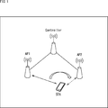
- FIG. 1 is a diagram showing a configuration example of a communication system according to an embodiment of the present technology.
- the communication system of FIG. 1 is configured by connecting access points (hereinafter referred to as APs) 1 and AP2 and a controller by wired communication or wireless communication. Further, the communication system is configured by connecting AP1 and AP2 and STA, which is a communication terminal, by wireless communication.
- APs access points
- STA STA
- AP1 and AP2 are communication devices that control the network within the reach of their respective radio waves.
- the Controller is a communication control device that controls the communication of a plurality of APs.
- the STA is a communication device that operates as a communication terminal belonging to a network managed by an AP and serves as a client.
- the STA is configured to be portable by the user, for example.
- BSS Basic Service Set
- BSS Base Service Set
- the Controller is configured as a single communication control device, but since it is defined as an Entity, it may be configured as one function of the communication device that functions as any AP. .. Further, the communication control device may also execute the operation of the Controller and the operation of the AP.
- AP1 is the switching source AP
- AP2 is the switching destination AP
- AP1 is communicating with STA as shown by the solid arrow.
- AP1 sends a switching inquiry frame for switching the connection destination of STA to the Controller in response to the BSS Transition Management Query frame sent from STA.
- the BSS migration inquiry frame is a frame in which information regarding inquiries for STA to migrate from AP1 BSS to AP2 BSS is described.
- the switch query frame contains information about the connection used to connect between AP1 and STA, in addition to the information contained in the BSS migration query frame. Details of the connection information will be described later.
- AP2 sends a switching response frame indicating that it is possible to respond to the switching of the connection destination to the STA in response to the switching request frame that requests the switching of the connection destination of the STA sent from the Controller.
- the Controller receives the switching inquiry frame sent from AP1.
- the Controller acquires information about the connection from the switching inquiry frame.
- the Controller sends a switching request frame containing information about the connection to AP2, and causes AP2 to generate a switching response frame based on the information about the connection included in the switching request frame.
- STA sends a BSS migration inquiry frame to AP1 when the communication quality with AP1 deteriorates.
- the STA receives the switching response frame transmitted from AP2.
- the STA as indicated by the dotted arrow, if the switch response frame sent by AP2 was addressed to itself and could be decrypted based on the information about the connection used to connect between AP1 and STA. Switch the connection destination to AP2.
- STA can smoothly switch the AP of the connection destination.
- FIG. 2 is a block diagram showing a configuration example of a communication device.
- the communication device 21 shown in FIG. 2 is a device that operates as an AP.
- the communication device 21 is composed of a control unit 31, a data processing unit 32, a wireless communication unit 33, and a wired communication unit 34.
- the control unit 31 is composed of a CPU (Central Processing Unit), a ROM (Read Only Memory), a RAM (Random Access Memory), and the like.
- the control unit 31 executes a program stored in a ROM or the like to control the overall operation of the communication device 21.
- the control unit 31 controls each unit so as to generate a switching inquiry frame, including information such as a common key used for connection with the STA, for example.
- control unit 31 controls the data processing unit 32 to generate, for example, a packet that can be decrypted by the STA based on the information about the connection used for the connection between the other AP and the STA.
- the control content to be notified to the Controller or STA is also determined by the control unit 31.
- the data processing unit 32 processes various data signals to be transmitted and received. Specifically, the data processing unit 32 performs a process of generating a data signal to be included in a packet and transmitted, and a process of extracting a data signal from the demodulated received signal.
- the data signal includes both communication data exchanged between the backhaul line and the STA, and control data including the control content determined by the control unit 31.
- the wireless communication unit 33 communicates with the STA under the network.
- the wireless communication unit 33 also communicates with other APs or controllers constituting the network.
- the wireless communication unit 33 is composed of a wireless reception unit 41 and a wireless transmission unit 42.
- the wireless receiving unit 41 performs RF processing and digital conversion on the received signal supplied from the antenna, and extracts a data signal composed of packets.
- the wireless transmission unit 42 performs analog conversion and RF processing on the data signal composed of the packets generated by the data processing unit 32, generates a transmission signal, and outputs the transmission signal to the antenna.
- the antenna emits the transmission signal generated by the wireless transmission unit 42 as an electromagnetic wave. Further, the electromagnetic wave received by the antenna is output to the wireless reception unit 41 as a reception signal.
- the wired communication unit 34 mainly performs communication with the backhaul line or communication with the AP or Controller constituting the network.
- the wired communication unit 34 is composed of a wired receiving unit 43 and a wired transmitting unit 44.
- the wired receiving unit 43 extracts a data signal from the received signal acquired via the wired cable.
- the wired transmission unit 44 generates a transmission signal output to the wired cable from the data signal generated by the data processing unit 32.
- the communication device 21 includes one wireless communication unit 33 and one wired communication unit 34, a plurality of each may be provided.
- the plurality of wired communication units 34 can be configured to properly use the connection with the backhaul line and the connection with the controller.
- the plurality of wireless communication units 33 can be configured to correspond to different frequencies (2.4 GHz band / 5 GHz band).
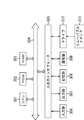
- FIG. 3 is a block diagram showing a configuration example of the communication control device.
- the communication control device 51 shown in FIG. 3 is a device that operates as a controller.
- the communication control device 51 is composed of a control unit 31, a data processing unit 32, a wireless communication unit 33, a wired communication unit 34, and a network control unit 61.
- the configuration of the communication control device 51 shown in FIG. 3 is different from the configuration of the communication device 21 shown in FIG. 2 in that the network control unit 61 is provided.
- the control unit 31 in FIG. 3 controls each unit so as to generate a switching request frame, including information such as a common key used for the connection between the AP and the STA, for example.
- the wireless communication unit 33 communicates with the AP or STA that constitutes the network.
- the wired communication unit 34 mainly performs communication with the backhaul line or communication with the AP or STA constituting the network.
- the network control unit 61 collects information from APs constituting the same network and performs various controls. For example, the network control unit 61 collects information such as Link information, and performs frequency control and the like.
- the network control unit 61 controls the data processing unit 32 so that when the information regarding the connection between the AP and the STA is received, the switching response frame to be transmitted to the STA is generated by the switching destination AP.
- the communication control device 51 may be any device having a network control unit 61, and may have either a wireless communication unit 33 or a wired communication unit 34. Further, when the communication control device 51 has the wireless communication unit 33, it can also operate as an AP.
- FIG. 4 is a block diagram showing a configuration example of a communication terminal.
- the communication terminal 81 shown in FIG. 4 is a device that operates as an STA.
- the communication terminal 81 is composed of a control unit 31, a data processing unit 32, and a wireless communication unit 33.
- a control unit 31 a data processing unit 32
- a wireless communication unit 33 a wireless communication unit 33.
- FIG. 4 the same configurations as those described with reference to FIG. 2 are designated by the same reference numerals. Duplicate explanations will be omitted.
- the configuration of the communication terminal 81 shown in FIG. 4 is different from the configuration of the communication device 21 shown in FIG. 2 in that the wired communication unit 34 is excluded.
- the control unit 31 in FIG. 4 controls each unit so as to generate a BSS transition inquiry frame when, for example, the communication quality with the AP1 deteriorates.
- control unit 31 controls the data processing unit 32 and decodes the switching response frame by using the same common key as the common key used for the connection between the AP and the STA.
- the wireless communication unit 33 communicates with the AP or Controller that constitutes the network.
- FIG. 5 is a diagram showing a sequence for explaining a series of conventional operation of switching the connection destination.
- step S1 the STA receives the downlink (DL) frame transmitted from AP1.
- DL downlink
- the STA in step S2 , Send a BSS migration query frame to AP1.
- RSSI Received Signal Strength Indicator
- FIG. 6 is a diagram showing a configuration example of the frame format of the BSS migration inquiry frame.
- the BSS migration inquiry frame includes Category, WNMAction, DialogToken, BSSTransitionQueryReason, and BSSTransitionCandidateListEntries.
- Dialog Token indicates the processing number.
- BSS Transition Query Reason indicates the reason for connection switching, such as a decrease in the reception rate.
- BSS Transition Candidate List Entries shows a list of candidates for connection switching destinations.
- step S11 of FIG. 5 AP1 receives the BSS transition inquiry frame transmitted from the STA.
- step S12 AP1 determines AP2 as the switching destination AP based on the BSS migration inquiry frame, and transmits a BSS transition request (BSS Transition Management Request) frame requesting migration to AP2 to the STA.
- BSS transition request BSS Transition Management Request
- FIG. 7 is a diagram showing a configuration example of the frame format of the BSS migration request frame.
- the BSS migration request frame includes Category, WNMAction, DialogToken, Requestmode, DisassociationTimer, ValidityInterval, BSSTerminationDuration, SessionInformationURL, and BSSTransitionCandidateListEntries.
- WNMAction DialogToken
- BSSTransitionCandidateListEntries are the same as Category, WNMAction, and DialogToken of the BSS migration inquiry frame.
- Request mode indicates whether or not to make a switching request.
- Disassociation Timer indicates when to send the request frame.
- Validity Interval indicates the validity period for switching the connection destination.
- BSSTerminationDuration indicates whether to send the frame immediately or after waiting.
- Session Information URL indicates information for connecting to an external network.
- step S3 of FIG. 5 the STA receives the BSS transition request frame transmitted from AP1.
- step S4 the STA returns a BSS transition response (BSS Transition Management Request) frame to AP1.
- BSS Transition Management Request BSS Transition Management Request
- FIG. 8 is a diagram showing a configuration example of the frame format of the BSS transition response frame.
- the BSS migration response frame includes Category, WNMAction, DialogToken, BTMStatusCode, BSSTerminationDelay, TargetBSSID, and BSSTransitionCandidateListEntries.
- WNMAction DialogToken
- BSSTransitionCandidateListEntries are the same as Category, WNMAction, and DialogToken of the BSS migration inquiry frame.
- BTM Status Code indicates the status of the BSS migration response frame.
- BSSTerminationDelay indicates the delay time for the end of connection switching.
- Target BSSID indicates the identification information of the BSS to be switched to.
- step S13 of FIG. 5 AP1 receives the BSS transition response frame transmitted from the STA.
- step S5 the STA transmits a reconnection request frame to AP2.
- the AP2 When the AP2 receives the reconnection request frame transmitted from the STA in step S21, the AP2 transmits the reconnection response frame to the STA in step S22.
- step S6 the STA receives the reconnection response frame transmitted from AP2.
- the conventional signal exchange as described above is the method specified in IEEE802.11k.
- the STA In such conventional signal exchange, the STA must receive the BSS migration request from AP1 before switching the connection destination, even though the communication quality of the connection with AP1 is deteriorated. There wasn't. Therefore, there is a risk that it takes time to switch the connection destination or the switching of the connection destination fails.
- AP2 is made to generate a frame indicating a connection switching response transmitted to the STA that switches the connection destination from AP1 to AP2 based on the information regarding the connection between AP1 and STA.
- the STA can receive the response frame generated by the AP2 of the switching destination, and can smoothly switch to the AP2 as the new connection destination.
- FIG. 9 is a sequence diagram illustrating a series of operations for switching the connection destination in the first embodiment of the present technology.
- step S41 the STA receives the DL frame transmitted from the AP1.
- the STA sends a BSS migration inquiry frame to AP1 in step S42.
- step S51 AP1 receives the BSS transition inquiry frame (FIG. 6) transmitted from the STA.
- step S52 AP1 transmits a switching inquiry frame to the Controller.
- AP1 sends information about the connection used for the connection between AP1 and STA in the switching inquiry frame.
- the connection information includes at least one such as a common key generated by device authentication, an AP1 MAC address, and a STA MAC address.
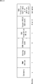
- FIG. 10 is a diagram showing a configuration example of the frame format of the switching inquiry frame.
- the configuration of the switching inquiry frame is different from the configuration of the BSS migration inquiry frame in FIG. 6 in that Connection Information is added.
- the switching inquiry frame includes Category, WNMAction, DialogToken, BSSTransitionQueryReason, BSSTransitionCandidateListEntries, and ConnectionInformation.
- Connection Information indicates the above-mentioned information related to the connection.
- step S61 of FIG. 9 the Controller receives the switching inquiry frame transmitted from AP1.
- step S62 the Controller transmits the switching request frame to the AP2 which is the connection destination.
- the switching request frame also contains information about the connection used for the connection between AP1 and STA, in addition to the BSS migration request frame shown in FIG.
- connection destination may be determined by the Controller or the STA.
- the Controller determines the connection destination, for example, the Controller causes the BSS Transition Candidate List Entries of the switching inquiry frame to describe each BSSID of the AP that can be switched by the STA and its RSSI in AP2.
- the Controller that receives the switching inquiry frame in which each BSSID of the AP that the STA can switch and its RSSI is described can determine the AP with the BSSID having the highest RSSI as a new connection destination.
- the Controller collects information such as BSS load or BSS Average Access Delay, which is information about the BSS including the AP, from the AP to which it is connected, and connects the STA based on the collected information. You may decide the destination.
- BSS load or BSS Average Access Delay which is information about the BSS including the AP, from the AP to which it is connected. You may decide the destination.
- FIG. 11 is a diagram showing a configuration example of the frame format of the switching request frame.
- the configuration of the switching request frame is different from the configuration of the BSS migration request frame of FIG. 7 in that the Connection Information shown in FIG. 10 is added.
- the switching request frame includes Category, WNMAction, DialogToken, Requestmode, DisassociationTimer, ValidityInterval, BSSTerminationDuration, SessionInformationURL, BSSTransitionCandidateListEntries, and ConnectionInformation.
- step S71 of FIG. 9 AP2 receives the switching request frame transmitted from the Controller.
- step S72 AP2 generates a switching response frame based on the connection information included in the switching request frame and transmits it to the STA.
- step S43 the STA receives the switching response frame transmitted from AP2. As a result, the STA switches the AP to connect to.
- step S72 the generation of the switching response frame in step S72 is controlled by the transmission of the switching request frame from the Controller to the AP2 in step S62.
- AP2 encrypts the switching response frame using the same common key used for the connection between AP1 and STA among the connection information, and sends it so that STA can decrypt it.
- AP2 sends a switching response frame to the MAC address of the STA so that the STA can receive it.
- at least one operation is performed by AP2.
- AP2 If AP2 cannot accept STA because the number of STAs under the network is already larger than the threshold number, AP2 describes information indicating that switching is not possible in the switching response frame. You may send it to STA.
- AP1 should not send to STA after receiving the BSS migration inquiry frame from STA.
- a switching response frame containing information indicating that AP2 cannot be switched is transmitted directly to AP1 or via a controller.
- AP1 receiving the switching response frame transmits the frame to STA.
- the STA can recognize that the connection cannot be switched by receiving the frame from the switching source AP1.
- AP1 or AP2 also serves as a controller.
- AP1 receives the BSS migration inquiry frame and sends the switching request frame to AP2 without transmitting the switching inquiry frame.
- AP2 receives a switching inquiry frame and sends a switching response frame to the STA according to the information included in the switching request frame generated by itself.
- FIG. 12 is a flowchart illustrating the processing of the Controller.
- the Controller may be configured as a single communication control device, but as described above, it may be configured as a communication device that functions as an AP, and the AP may also serve as the Controller.
- step S101 the controller control unit 31 (FIG. 2 or 3) determines whether or not it is the switching source AP (AP1).
- step S101 If it is determined in step S101 that it is configured as a single unit and is not the switching source AP (AP1), the process proceeds to step S102.
- step S102 the wireless receiving unit 41 receives the switching inquiry frame transmitted from AP1.
- the data processing unit 32 generates a switching request frame based on an instruction by the control unit 31, information collected by the network control unit 61, data extracted from the switching inquiry frame, and the like.
- step S101 If it is determined in step S101 that it is the switching source AP (AP1), step S102 is skipped and the process proceeds to step S103.
- the data processing unit 32 generates a switching request frame in response to an instruction from the control unit 31.
- step S103 the control unit 31 determines whether or not it is the switching destination AP (AP2).
- step S103 If it is determined in step S103 that it is composed of a single unit and is not the AP (AP2) to be switched to, the process proceeds to step S104.
- step S104 the wireless transmission unit 42 transmits the switching request frame generated by the data processing unit 32 to the AP2.
- step S103 If it is determined in step S103 that it is the AP (AP2) to be switched to, the process proceeds to step S105.
- the data processing unit 32 generates a switching response frame based on the instruction by the control unit 31 and the data extracted from the switching request frame generated by the data processing unit 32.
- step S105 the wireless transmission unit 42 transmits the switching response frame generated by the data processing unit 32 to the STA.
- step S104 When the switching request frame is transmitted to AP2 in step S104, or when the switching response frame is transmitted to STA in step S105, the controller processing ends.
- FIG. 13 is a flowchart illustrating the processing of the AP.
- step S121 the radio receiving unit 41 (FIG. 2) of the AP determines whether or not the BSS transition inquiry frame transmitted from the STA has been received.
- step S121 If it is determined in step S121 that the BSS transition inquiry frame has been received, the process proceeds to step S122.
- the AP is the connection switching source AP1.
- the data processing unit 32 generates a switching inquiry frame based on an instruction from the control unit 31 and data extracted from the BSS transition inquiry frame received by the wireless reception unit 41.
- step S122 the wireless transmission unit 42 transmits the switching inquiry frame generated by the data processing unit 32 to the controller.
- step S121 If it is determined in step S121 that the BSS transition inquiry has not been received, the process proceeds to step S123. In this case, the AP is the AP2 to switch to.
- step S123 the wireless reception unit 41 determines whether or not the switching request frame transmitted from the Controller has been received.
- step S123 If it is determined in step S123 that the switching request frame has been received, the process proceeds to step S124.
- the data processing unit 32 generates a switching response frame based on an instruction by the control unit 31 and data extracted from the switching request frame received by the wireless receiving unit 41.
- step S124 the wireless transmission unit 42 transmits the switching response frame generated by the data processing unit 32 to the STA.
- step S122 If the switching inquiry frame is transmitted to the Controller in step S122, or if the switching response frame is transmitted to the STA in step S124, the AP processing ends. Similarly, when it is determined in step S123 that the switching request frame has not been received, the AP process ends.
- FIG. 14 is a flowchart illustrating the processing of STA.
- the data processing unit 32 (FIG. 4) of the STA generates a BSS transition inquiry frame in response to an instruction from the control unit 31.
- step S141 the wireless transmission unit 42 transmits the BSS transition inquiry frame generated by the data processing unit 32 to the AP1.
- step S142 the radio receiving unit 41 determines whether or not the switching response frame indicated as switchable has been received.
- step S142 If it is determined in step S142 that the switching response frame indicated as switchable has been received, the process proceeds to step S143.
- the switching response frame encrypts the switching response frame with the same common key used for the connection between AP1 and STA in the information regarding the connection between AP1 and STA. It has been converted and sent so that the STA can decipher it. Further, the switching response frame is transmitted so that the STA can receive it with the MAC address of the STA as the destination.
- the data processing unit 32 extracts the data described in the switching response frame and extracts the data.
- the extracted data is output to the control unit 31.
- step S143 the control unit 31 controls the data processing unit 32 and the wireless communication unit 33 based on the data extracted from the switching response frame, and starts communication with the new connection destination AP2.
- step S143 If it is determined in step S143 that communication with AP2, which is the connection destination, has not been received, or if it is determined in step S142 that the switching response frame indicated as switchable has not been received, the STA process ends. ..
- Second embodiment (example of starting with AP)> Next, as a second embodiment, an example in which the AP starts switching the connection destination will be described.
- FIG. 15 is a sequence diagram illustrating a series of operations for switching the connection destination in the second embodiment of the present technology.
- AP1 and STA are connected and communicating.
- AP1 receives an uplink (UL) frame transmitted from the STA.
- UL uplink
- AP1 transmits a switching inquiry frame to the Controller in step S162.
- AP1 sends a switch query frame containing information about the connection used to connect between AP1 and STA.
- step S171 the Controller receives the switching inquiry frame transmitted from AP1.
- step S172 the Controller transmits a switching request frame to AP2, which is a new connection destination.
- the switching request frame also contains information about the connection used to connect AP1 and STA.
- step S181 AP2 receives the switching request frame transmitted from the Controller.
- step S182 AP2 generates a switching response frame based on the information regarding the connection and transmits it to the STA.
- step S191 the STA receives the switching response frame transmitted from the AP2. As a result, the STA switches the AP to connect to.
- the generation of the switching response frame in step S182 is controlled by the transmission of the switching request frame from the Controller to the AP2 in step S172.
- AP1 or AP2 also serves as a controller, as in the example of FIG. 15.
- FIG. 16 is a sequence diagram illustrating a series of operations for switching the connection destination in the third embodiment of the present technology.
- step S211 the Controller transmits a STA Steering Request frame indicating a request for controlling the STA to the AP1.
- step S221 AP1 receives the STA Steering Request frame transmitted from the Controller.
- step S222 AP1 transmits an ACK for the received STA Steering Request frame to the Controller.
- step S223 AP1 transmits a switching inquiry frame to the Controller.
- AP1 sends a switch query frame containing information about the connection used to connect between AP1 and STA.
- step S212 the Controller receives the ACK transmitted from AP1.
- step S213 the Controller receives the switching inquiry frame transmitted from AP1.
- step S214 the Controller transmits a switching request frame to AP2, which is a new connection destination.
- the switch request frame also contains information about the connection used to connect between AP1 and STA, in addition to the BSS migration request frame described above.
- step S231 AP2 receives the switching request frame transmitted from the Controller.
- step S232 AP2 generates a switching response frame based on the information regarding the connection and transmits it to the STA.
- step S241 the STA receives the switching response frame transmitted from the AP2. As a result, the STA switches the AP to connect to.
- step S232 the generation of the switching response frame in step S232 is controlled by the transmission of the switching request frame from the Controller to the AP2 in step S214.
- AP1 or AP2 also serves as a controller, as in the example of FIG. 16.
- connection destination can be switched to the switching destination AP without the STA receiving the frame from the switching source AP, so that the communication quality with the switching source AP can be changed. It is possible to reduce the risk that the switching of the connection destination will fail if the problem is bad.
- the switching destination AP since the switching destination AP sends a frame to the STA using the information about the connection between the switching source AP and the STA, the frame exchange procedure for establishing the connection between the STA and the switching destination AP. Can be reduced.
- FIG. 17 is a block diagram showing a configuration example of computer hardware that executes the above-mentioned series of processes programmatically.
- the CPU Central Processing Unit
- ROM Read Only Memory
- RAM Random Access Memory
- An input / output interface 305 is further connected to the bus 304.
- An input unit 306 including a keyboard and a mouse, and an output unit 307 including a display and a speaker are connected to the input / output interface 305.
- the input / output interface 305 is connected to a storage unit 308 made of a hard disk or a non-volatile memory, a communication unit 309 made of a network interface or the like, and a drive 310 for driving the removable media 311.
- the CPU 301 loads the program stored in the storage unit 308 into the RAM 303 via the input / output interface 305 and the bus 304 and executes the program, thereby executing the series of processes described above. Is done.
- the program executed by the CPU 301 is recorded on the removable media 311 or provided via a wired or wireless transmission medium such as a local area network, the Internet, or a digital broadcast, and is installed in the storage unit 308.
- the program executed by the computer may be a program that is processed in chronological order according to the order described in this specification, or may be a program that is processed in parallel or at a necessary timing such as when a call is made. It may be a program in which processing is performed.
- the system means a set of a plurality of components (devices, modules (parts), etc.), and it does not matter whether all the components are in the same housing. Therefore, a plurality of devices housed in separate housings and connected via a network, and a device in which a plurality of modules are housed in one housing are both systems. ..
- this technology can have a cloud computing configuration in which one function is shared and jointly processed by a plurality of devices via a network.
- each step described in the above flowchart can be executed by one device or can be shared and executed by a plurality of devices.
- one step includes a plurality of processes
- the plurality of processes included in the one step can be executed by one device or shared by a plurality of devices.
- the present technology can also have the following configurations.
- a switching response frame indicating a connection switching response transmitted to a communication terminal that switches the connection destination from the first communication device to the second communication device is connected between the first communication device and the communication terminal.
- a communication control device including a control unit that causes the second communication device to generate based on information about the above.
- the communication according to (1), wherein the information regarding the connection includes at least one of a common key generated by device authentication, a MAC address of the first communication device, and a MAC address of the communication terminal. Control device.
- (4) Further including a transmission unit that transmits a switching request frame indicating a connection switching request including information on the connection to the second communication device.
- the communication control device according to (1) or (2), wherein the control unit causes the second communication device to generate the switching response frame based on the switching request frame.
- (5) Further provided with a receiver for receiving a transition inquiry frame indicating a connection transition inquiry transmitted from the communication terminal.
- the communication control device according to (4) above, wherein the control unit generates a switching inquiry frame indicating a connection switching inquiry based on the transition inquiry frame.
- (6) Further comprising a receiving unit for receiving a switching inquiry frame indicating a connection switching inquiry including information on the connection transmitted from the first communication device.
- the communication control device according to (4), wherein the control unit generates the switching request frame based on the switching inquiry frame. (7) The communication control device according to (6) above, wherein the control unit determines the second communication device based on the switching inquiry frame.
- the communication control device A switching response frame indicating a connection switching response transmitted to a communication terminal that switches the connection destination from the first communication device to the second communication device is connected between the first communication device and the communication terminal. A communication control method for causing the second communication device to generate based on the information regarding the above. (9) A receiver that receives a switching response frame that indicates a connection switching response that is generated and transmitted by the second communication device based on information about the connection to and from the first communication device.
- a communication terminal including a control unit that switches a connection destination from the first communication device to the second communication device when the switching response frame is decoded.
- the communication unit further includes a transmission unit that transmits a transition inquiry frame indicating a connection transition inquiry to the first communication device.
- the receiving unit is a switching response frame generated and transmitted by the second communication device based on a switching request frame indicating a connection switching request in which information about the connection is added to the connection transition inquiry.
- the communication terminal according to (9) above.
- the information regarding the connection is described in (9) or (10) above, which includes at least one of a common key generated by device authentication, a MAC address of the first communication device, and its own MAC address. Communication terminal.
- the communication terminal Receives a switching response frame indicating the connection switching response generated and transmitted by the second communication device based on the information regarding the connection with the first communication device.
Landscapes
- Engineering & Computer Science (AREA)
- Computer Networks & Wireless Communication (AREA)
- Signal Processing (AREA)
- Computer Security & Cryptography (AREA)
- Mobile Radio Communication Systems (AREA)
Abstract
Description
0.システムおよび装置の構成例
1.第1の実施の形態(STAによる開始の例)
2.第2の実施の形態(APによる開始の例)
3.第3の実施の形態(Controllerによる開始の例)
4.第4の実施の形態(コンピュータ)
<通信システムの構成例>
図1は、本技術の実施の形態に係る通信システムの構成例を示す図である。
図2は、通信装置の構成例を示すブロック図である。
図3は、通信制御装置の構成例を示すブロック図である。
図4は、通信端末の構成例を示すブロック図である。
まず、第1の実施の形態として、STAによって接続先の切り替えが開始される例について説明する。
図5は、従来の接続先の切り替えの一連の動作について説明するシーケンスを示す図である。
図9は、本技術の第1の実施の形態における接続先の切り替えの一連の動作について説明するシーケンス図である。
図12は、Controllerの処理について説明するフローチャートである。
次に、第2の実施の形態として、APによって接続先の切り替えが開始される例について説明する。
図15は、本技術の第2の実施の形態における接続先の切り替えの一連の動作について説明するシーケンス図である。
次に、第3の実施の形態として、Controllerによって接続先の切り替えが開始される例について説明する。
図16は、本技術の第3の実施の形態における接続先の切り替えの一連の動作について説明するシーケンス図である。
<コンピュータの構成例>
上述した一連の処理は、ハードウェアにより実行することもできるし、ソフトウェアにより実行することもできる。一連の処理をソフトウェアにより実行する場合には、そのソフトウェアを構成するプログラムが、専用のハードウェアに組み込まれているコンピュータ、または汎用のパーソナルコンピュータなどに、プログラム記録媒体からインストールされる。
本技術は、以下のような構成をとることもできる。
(1)
第1の通信装置から第2の通信装置に接続先を切り替える通信端末に対して送信される接続切り替えの応答を示す切り替え応答フレームを、前記第1の通信装置と前記通信端末との間の接続に関する情報に基づいて前記第2の通信装置に生成させる制御部を備える
通信制御装置。
(2)
前記接続に関する情報は、機器認証によって生成される共通鍵、前記第1の通信装置のMACアドレス、および前記通信端末のMACアドレスのうち、少なくともいずれか1つを含む
前記(1)に記載の通信制御装置。
(3)
前記切り替え応答フレームを前記通信端末に送信する送信部をさらに備える
前記(1)または(2)に記載の通信制御装置。
(4)
前記接続に関する情報を含む接続切り替えの要求を示す切り替え要求フレームを前記第2の通信装置に送信する送信部をさらに備え、
前記制御部は、前記切り替え要求フレームに基づいて、前記第2の通信装置に前記切り替え応答フレームを生成させる
前記(1)または(2)に記載の通信制御装置。
(5)
前記通信端末から送信されてくる接続移行の問い合わせを示す移行問い合わせフレームを受信する受信部をさらに備え、
前記制御部は、前記移行問い合わせフレームに基づいて、接続切り替えの問い合わせを示す切り替え問い合わせフレームを生成する
前記(4)に記載の通信制御装置。
(6)
前記第1の通信装置から送信されてくる前記接続に関する情報を含む接続切り替えの問い合わせを示す切り替え問い合わせフレームを受信する受信部をさらに備え、
前記制御部は、前記切り替え問い合わせフレームに基づいて、前記切り替え要求フレームを生成する
前記(4)に記載の通信制御装置。
(7)
前記制御部は、前記切り替え問い合わせフレームに基づいて、前記第2の通信装置を決定する
前記(6)に記載の通信制御装置。
(8)
通信制御装置が、
第1の通信装置から第2の通信装置に接続先を切り替える通信端末に対して送信される接続切り替えの応答を示す切り替え応答フレームを、前記第1の通信装置と前記通信端末との間の接続に関する情報に基づいて前記第2の通信装置に生成させる
通信制御方法。
(9)
第1の通信装置との間の接続に関する情報に基づいて第2の通信装置により生成され、送信されてくる接続切り替えの応答を示す切り替え応答フレームを受信する受信部と、
前記切り替え応答フレームを復号した場合、前記第1の通信装置から前記第2の通信装置に接続先を切り替える制御部と
を備える通信端末。
(10)
前記通信部は、接続移行の問い合わせを示す移行問い合わせフレームを前記第1の通信装置に送信する送信部をさらに備え、
前記受信部は、前記接続移行の問い合わせに前記接続に関する情報が追加されてなる接続切り替えの要求を示す切り替え要求フレームに基づいて前記第2の通信装置により生成され、送信されてくる前記切り替え応答フレームを受信する
前記(9)に記載の通信端末。
(11)
前記接続に関する情報は、機器認証によって生成される共通鍵、前記第1の通信装置のMACアドレス、および自身のMACアドレスのうち、少なくともいずれか1つを含む
前記(9)または(10)に記載の通信端末。
(12)
通信端末が、
第1の通信装置との間の接続に関する情報に基づいて第2の通信装置により生成され、送信されてくる接続切り替えの応答を示す切り替え応答フレームを受信し、
前記切り替え応答フレームを復号した場合、前記第1の通信装置から前記第2の通信装置に接続先を切り替える
通信方法。
Claims (12)
- 第1の通信装置から第2の通信装置に接続先を切り替える通信端末に対して送信される接続切り替えの応答を示す切り替え応答フレームを、前記第1の通信装置と前記通信端末との間の接続に関する情報に基づいて前記第2の通信装置に生成させる制御部を備える
通信制御装置。 - 前記接続に関する情報は、機器認証によって生成される共通鍵、前記第1の通信装置のMACアドレス、および前記通信端末のMACアドレスのうち、少なくともいずれか1つを含む
請求項1に記載の通信制御装置。 - 前記切り替え応答フレームを前記通信端末に送信する送信部をさらに備える
請求項1に記載の通信制御装置。 - 前記接続に関する情報を含む接続切り替えの要求を示す切り替え要求フレームを前記第2の通信装置に送信する送信部をさらに備え、
前記制御部は、前記切り替え要求フレームに基づいて、前記第2の通信装置に前記切り替え応答フレームを生成させる
請求項1に記載の通信制御装置。 - 前記通信端末から送信されてくる接続移行の問い合わせを示す移行問い合わせフレームを受信する受信部をさらに備え、
前記制御部は、前記移行問い合わせフレームに基づいて、接続切り替えの問い合わせを示す切り替え問い合わせフレームを生成する
請求項4に記載の通信制御装置。 - 前記第1の通信装置から送信されてくる前記接続に関する情報を含む接続切り替えの問い合わせを示す切り替え問い合わせフレームを受信する受信部をさらに備え、
前記制御部は、前記切り替え問い合わせフレームに基づいて、前記切り替え要求フレームを生成する
請求項4に記載の通信制御装置。 - 前記制御部は、前記切り替え問い合わせフレームに基づいて、前記第2の通信装置を決定する
請求項6に記載の通信制御装置。 - 通信制御装置が、
第1の通信装置から第2の通信装置に接続先を切り替える通信端末に対して送信される接続切り替えの応答を示す切り替え応答フレームを、前記第1の通信装置と前記通信端末との間の接続に関する情報に基づいて前記第2の通信装置に生成させる
通信制御方法。 - 第1の通信装置との間の接続に関する情報に基づいて第2の通信装置により生成され、送信されてくる接続切り替えの応答を示す切り替え応答フレームを受信する受信部と、
前記切り替え応答フレームを復号した場合、前記第1の通信装置から前記第2の通信装置に接続先を切り替える制御部と
を備える通信端末。 - 接続移行の問い合わせを示す移行問い合わせフレームを前記第1の通信装置に送信する送信部をさらに備え、
前記受信部は、前記接続移行の問い合わせに前記接続に関する情報が追加されてなる接続切り替えの要求を示す切り替え要求フレームに基づいて前記第2の通信装置により生成され、送信されてくる前記切り替え応答フレームを受信する
請求項9に記載の通信端末。 - 前記接続に関する情報は、機器認証によって生成される共通鍵、前記第1の通信装置のMACアドレス、および自身のMACアドレスのうち、少なくともいずれか1つを含む
請求項9に記載の通信端末。 - 通信端末が、
第1の通信装置との間の接続に関する情報に基づいて第2の通信装置により生成され、送信されてくる接続切り替えの応答を示す切り替え応答フレームを受信し、
前記切り替え応答フレームを復号した場合、前記第1の通信装置から前記第2の通信装置に接続先を切り替える
通信方法。
Priority Applications (6)
| Application Number | Priority Date | Filing Date | Title |
|---|---|---|---|
| EP20778658.3A EP3944669A4 (en) | 2019-03-22 | 2020-03-06 | COMMUNICATION CONTROL DEVICE AND METHOD AND COMMUNICATION TERMINAL DEVICE AND METHOD |
| CN202080021336.XA CN113574932B (zh) | 2019-03-22 | 2020-03-06 | 通信控制设备、通信控制方法、通信终端和通信方法 |
| US17/430,324 US11968579B2 (en) | 2019-03-22 | 2020-03-06 | Communication control device, communication control method, communication terminal, and communication method for switching a terminal from a first connection to a second connection |
| JP2021508937A JP7456432B2 (ja) | 2019-03-22 | 2020-03-06 | 通信制御装置および方法、並びに、通信端末および方法 |
| US18/636,476 US12267733B2 (en) | 2019-03-22 | 2024-04-16 | Communication control device, communication control method, communication terminal, and communication method for switching a terminal from a first connection to a second connection |
| US19/086,435 US20250220513A1 (en) | 2019-03-22 | 2025-03-21 | Communication control device, communication control method, communication terminal, and communication method for switching a terminal from a first connection to a second connection |
Applications Claiming Priority (2)
| Application Number | Priority Date | Filing Date | Title |
|---|---|---|---|
| JP2019054045 | 2019-03-22 | ||
| JP2019-054045 | 2019-03-22 |
Related Child Applications (2)
| Application Number | Title | Priority Date | Filing Date |
|---|---|---|---|
| US17/430,324 A-371-Of-International US11968579B2 (en) | 2019-03-22 | 2020-03-06 | Communication control device, communication control method, communication terminal, and communication method for switching a terminal from a first connection to a second connection |
| US18/636,476 Continuation US12267733B2 (en) | 2019-03-22 | 2024-04-16 | Communication control device, communication control method, communication terminal, and communication method for switching a terminal from a first connection to a second connection |
Publications (1)
| Publication Number | Publication Date |
|---|---|
| WO2020195704A1 true WO2020195704A1 (ja) | 2020-10-01 |
Family
ID=72610069
Family Applications (1)
| Application Number | Title | Priority Date | Filing Date |
|---|---|---|---|
| PCT/JP2020/009656 Ceased WO2020195704A1 (ja) | 2019-03-22 | 2020-03-06 | 通信制御装置および方法、並びに、通信端末および方法 |
Country Status (5)
| Country | Link |
|---|---|
| US (3) | US11968579B2 (ja) |
| EP (1) | EP3944669A4 (ja) |
| JP (1) | JP7456432B2 (ja) |
| CN (1) | CN113574932B (ja) |
| WO (1) | WO2020195704A1 (ja) |
Cited By (3)
| Publication number | Priority date | Publication date | Assignee | Title |
|---|---|---|---|---|
| US20240259902A1 (en) * | 2019-03-22 | 2024-08-01 | Sony Group Corporation | Communication control device, communication control method, communication terminal, and communication method for switching a terminal from a first connection to a second connection |
| WO2025070162A1 (ja) * | 2023-09-29 | 2025-04-03 | キヤノン株式会社 | 電子機器及びその制御方法、プログラム、記憶媒体 |
| JP2025517565A (ja) * | 2022-05-30 | 2025-06-05 | 中興通訊股▲ふん▼有限公司 | non-AP MLDの通信方法及び装置、コンピュータプログラム並びに電子装置 |
Families Citing this family (1)
| Publication number | Priority date | Publication date | Assignee | Title |
|---|---|---|---|---|
| US12513511B2 (en) * | 2023-05-12 | 2025-12-30 | Cisco Technology, Inc. | Using 802.11v action report messages to enhance roaming |
Citations (5)
| Publication number | Priority date | Publication date | Assignee | Title |
|---|---|---|---|---|
| JP2006222549A (ja) * | 2005-02-08 | 2006-08-24 | Nec Corp | 無線lanシステムにおけるローミング方法および無線lanシステム |
| JP2008034906A (ja) * | 2006-07-26 | 2008-02-14 | Matsushita Electric Ind Co Ltd | 無線基地局ハンドオーバ方法、及びデータ通信システム、並びに無線基地局、中継装置 |
| JP2015046849A (ja) | 2013-07-30 | 2015-03-12 | サイレックス・テクノロジー株式会社 | 無線通信システム、無線通信システムの制御方法、プログラム、及び、無線基地局装置 |
| US20160007278A1 (en) * | 2013-03-15 | 2016-01-07 | Ruckus Wireless, Inc. | Distribution of Clients Across a Network |
| US20160302144A1 (en) * | 2015-04-08 | 2016-10-13 | Nokia Technologies Oy | Method, apparatus, and computer program product for efficient use of frequency bands and channels in wireless environment |
Family Cites Families (30)
| Publication number | Priority date | Publication date | Assignee | Title |
|---|---|---|---|---|
| US6587680B1 (en) * | 1999-11-23 | 2003-07-01 | Nokia Corporation | Transfer of security association during a mobile terminal handover |
| AU2003270054A1 (en) * | 2002-09-03 | 2004-03-29 | Thomson Licensing S.A. | Mechanism for providing quality of service in a network utilizing priority and reserved bandwidth protocols |
| KR20050104191A (ko) * | 2004-04-28 | 2005-11-02 | 삼성전자주식회사 | 액세스 포인트간의 핸드오버를 지원 또는 수행하는 방법및 장치 |
| JP4687211B2 (ja) * | 2005-04-14 | 2011-05-25 | 沖電気工業株式会社 | アクセスポイント装置、該装置のハンドオーバ処理方法及び通信システム |
| EP2034751B1 (en) * | 2006-06-06 | 2017-08-23 | Panasonic Intellectual Property Management Co., Ltd. | Radio communication system, radio terminal, base station, and base station search method |
| CN101111056B (zh) * | 2006-07-17 | 2010-05-12 | 西安电子科技大学 | 在无线局域网中的快速切换方法 |
| KR20080114469A (ko) * | 2007-06-25 | 2008-12-31 | 엘지전자 주식회사 | 네트워크 부하 균형을 위한 무선 네트워크의 관리 방법 |
| US8223721B2 (en) | 2007-11-29 | 2012-07-17 | Nokia Siemens Networks Oy | Mobile station handover using transferrable virtual access point address for wireless networks |
| JP2009218929A (ja) | 2008-03-11 | 2009-09-24 | Toshiba Corp | 基地局、移動端末および通信プログラム |
| US8798632B2 (en) | 2008-06-13 | 2014-08-05 | Nokia Corporation | Methods, apparatuses, and computer program products for providing fresh security context during intersystem mobility |
| JP5294746B2 (ja) * | 2008-07-31 | 2013-09-18 | キヤノン株式会社 | 通信システムおよび通信システムの制御方法 |
| EP2721775B1 (en) * | 2011-06-20 | 2016-03-02 | Plexxi Inc. | Optical architecture and channel plan employing multi-fiber configurations for data center network switching |
| US8832820B2 (en) * | 2012-06-25 | 2014-09-09 | International Business Machines Corporation | Isolation and security hardening among workloads in a multi-tenant networked environment |
| JP5992267B2 (ja) * | 2012-09-05 | 2016-09-14 | 富士通株式会社 | イーサネットスイッチおよび通信方法 |
| US9402226B2 (en) * | 2012-11-12 | 2016-07-26 | Qualcomm Incorporated | Station, method, and apparatus for network detection in a wireless communications system |
| US10028179B2 (en) | 2013-05-31 | 2018-07-17 | Qualcomm Incorporated | Reducing signaling during AP to AP handoff in dense networks |
| GB2527518A (en) | 2014-06-23 | 2015-12-30 | Nec Corp | Communication system |
| US10111164B2 (en) * | 2014-07-14 | 2018-10-23 | Mitsubishi Electric Corporation | Wireless communication system and wireless communication method |
| US20160073316A1 (en) * | 2014-09-08 | 2016-03-10 | Futurewei Technologies, Inc. | System and Method for Inter-Radio Access Technology Handoff |
| CN105744579B (zh) * | 2014-12-11 | 2019-06-18 | 华为技术有限公司 | 终端在ap间切换的方法、切换控制装置及接入装置 |
| CN104703235B (zh) * | 2015-03-19 | 2018-06-19 | 北京邮电大学 | 一种高速移动下的终端切换方法 |
| JP6477239B2 (ja) * | 2015-05-21 | 2019-03-06 | 富士ゼロックス株式会社 | 情報処理装置、接続制御方法およびプログラム |
| CN105072650A (zh) | 2015-07-15 | 2015-11-18 | 西安电子科技大学 | 一种实现移动终端在ap间快速切换的通信系统及通信方法 |
| JP6785453B2 (ja) * | 2015-11-05 | 2020-11-18 | パナソニックIpマネジメント株式会社 | 基地局装置、無線端末装置および無線通信方法 |
| JP6649132B2 (ja) * | 2016-03-09 | 2020-02-19 | パナソニック インテレクチュアル プロパティ コーポレーション オブ アメリカPanasonic Intellectual Property Corporation of America | 通信端末、通信装置および通信システム |
| CN108235384B (zh) * | 2016-12-12 | 2020-10-16 | 华为技术有限公司 | 一种无线网络切换方法和装置 |
| US10432463B2 (en) | 2016-12-23 | 2019-10-01 | Neutrino8, Inc. | Fast BSS transitions between access points for stations of cloud-controlled Wi-Fi networks |
| WO2018217901A1 (en) | 2017-05-24 | 2018-11-29 | Intel IP Corporation | Multi-connectivity coordination |
| JP2022051969A (ja) * | 2019-01-15 | 2022-04-04 | ソニーグループ株式会社 | 無線装置、および無線装置の無線通信方法、無線端末、および無線端末の無線通信方法、並びに無線基地局、および無線基地局の無線通信方法 |
| CN113574932B (zh) * | 2019-03-22 | 2025-05-02 | 索尼集团公司 | 通信控制设备、通信控制方法、通信终端和通信方法 |
-
2020
- 2020-03-06 CN CN202080021336.XA patent/CN113574932B/zh active Active
- 2020-03-06 JP JP2021508937A patent/JP7456432B2/ja active Active
- 2020-03-06 US US17/430,324 patent/US11968579B2/en active Active
- 2020-03-06 WO PCT/JP2020/009656 patent/WO2020195704A1/ja not_active Ceased
- 2020-03-06 EP EP20778658.3A patent/EP3944669A4/en active Pending
-
2024
- 2024-04-16 US US18/636,476 patent/US12267733B2/en active Active
-
2025
- 2025-03-21 US US19/086,435 patent/US20250220513A1/en active Pending
Patent Citations (5)
| Publication number | Priority date | Publication date | Assignee | Title |
|---|---|---|---|---|
| JP2006222549A (ja) * | 2005-02-08 | 2006-08-24 | Nec Corp | 無線lanシステムにおけるローミング方法および無線lanシステム |
| JP2008034906A (ja) * | 2006-07-26 | 2008-02-14 | Matsushita Electric Ind Co Ltd | 無線基地局ハンドオーバ方法、及びデータ通信システム、並びに無線基地局、中継装置 |
| US20160007278A1 (en) * | 2013-03-15 | 2016-01-07 | Ruckus Wireless, Inc. | Distribution of Clients Across a Network |
| JP2015046849A (ja) | 2013-07-30 | 2015-03-12 | サイレックス・テクノロジー株式会社 | 無線通信システム、無線通信システムの制御方法、プログラム、及び、無線基地局装置 |
| US20160302144A1 (en) * | 2015-04-08 | 2016-10-13 | Nokia Technologies Oy | Method, apparatus, and computer program product for efficient use of frequency bands and channels in wireless environment |
Non-Patent Citations (3)
| Title |
|---|
| "Eldad Perahia (HPE-Aruba), client management preso", IEEE 802.11-17/0620R0, 25 April 2017 (2017-04-25), pages 1 - 7, XP009530189, Retrieved from the Internet <URL:https://mentor.ieee.org/802.11/dcn/17/11-17-0620-00-00ax-client-management-preso.pptx> * |
| ALFRED ASTERJADHI: "LB230-MAC-CR-11.24", IEEE 802. 11-18/0041R1, 5 January 2018 (2018-01-05), pages 1 - 4, XP055844330, Retrieved from the Internet <URL:https://mentor.ieee.org/802.11/dcn/18/11-18-0041-01-00ax-1b230-mac-cr-11-24.docx> * |
| See also references of EP3944669A4 |
Cited By (5)
| Publication number | Priority date | Publication date | Assignee | Title |
|---|---|---|---|---|
| US20240259902A1 (en) * | 2019-03-22 | 2024-08-01 | Sony Group Corporation | Communication control device, communication control method, communication terminal, and communication method for switching a terminal from a first connection to a second connection |
| US12267733B2 (en) * | 2019-03-22 | 2025-04-01 | Sony Group Corporation | Communication control device, communication control method, communication terminal, and communication method for switching a terminal from a first connection to a second connection |
| JP2025517565A (ja) * | 2022-05-30 | 2025-06-05 | 中興通訊股▲ふん▼有限公司 | non-AP MLDの通信方法及び装置、コンピュータプログラム並びに電子装置 |
| JP7852089B2 (ja) | 2022-05-30 | 2026-04-27 | 中興通訊股▲ふん▼有限公司 | non-AP MLDの通信方法及び装置、コンピュータプログラム並びに電子装置 |
| WO2025070162A1 (ja) * | 2023-09-29 | 2025-04-03 | キヤノン株式会社 | 電子機器及びその制御方法、プログラム、記憶媒体 |
Also Published As
| Publication number | Publication date |
|---|---|
| JP7456432B2 (ja) | 2024-03-27 |
| US12267733B2 (en) | 2025-04-01 |
| US11968579B2 (en) | 2024-04-23 |
| CN113574932B (zh) | 2025-05-02 |
| US20220132382A1 (en) | 2022-04-28 |
| EP3944669A1 (en) | 2022-01-26 |
| CN113574932A (zh) | 2021-10-29 |
| US20240259902A1 (en) | 2024-08-01 |
| JPWO2020195704A1 (ja) | 2020-10-01 |
| US20250220513A1 (en) | 2025-07-03 |
| EP3944669A4 (en) | 2022-04-27 |
Similar Documents
| Publication | Publication Date | Title |
|---|---|---|
| US12267733B2 (en) | Communication control device, communication control method, communication terminal, and communication method for switching a terminal from a first connection to a second connection | |
| JP4317882B2 (ja) | 無線通信システムおよび監視装置 | |
| JP3636695B2 (ja) | 無線通信システムにおける中継端末装置及び中継端末プログラム | |
| EP2832172B1 (en) | Systems and methods for registration and maintenance of wireless clients via a proxy wireless network service. | |
| US9980253B2 (en) | Wireless communication device, wireless communication method, and computer-readable recording medium storing wireless communication program | |
| US11096065B2 (en) | Apparatus and method for providing enhanced wireless coverage, improved service performance, and reduced battery power consumption | |
| CN118202701A (zh) | 接入点及通信方法 | |
| CN113455026A (zh) | 接入方法及通信装置 | |
| JP5036751B2 (ja) | 最適無線通信方式の選択方法 | |
| US20250240655A1 (en) | Wireless communication device | |
| WO2022149316A1 (ja) | 基地局、通信装置及び通信方法 | |
| CN115395998A (zh) | 一种消息解码方法、发送端和接收端 | |
| US9743325B2 (en) | Communication apparatus, storage apparatus, and control method | |
| JP7259999B2 (ja) | 基地局、端末、及び無線通信方法 | |
| CN114071504B (zh) | 执行中心协调功能的方法和装置 | |
| JP2018148279A (ja) | 通信装置、通信装置の制御方法、およびプログラム | |
| WO2024174961A1 (zh) | 一种设备通信的方法、装置、设备及系统 | |
| JP2025156890A (ja) | 通信装置およびその制御方法 | |
| WO2025182872A1 (ja) | 通信制御装置及び通信制御方法 | |
| CN119278647A (zh) | 操作参数协商方法、电子设备及存储介质 | |
| CN119835732A (zh) | 网络接入方法、装置、设备、系统及存储介质 | |
| CN117044309A (zh) | 休眠周期协商方法、电子设备及存储介质 | |
| JP2005101872A (ja) | ネットワーク制御方法、ネットワークシステムおよび無線端末 | |
| KR20130067153A (ko) | 프로토콜 변환 게이트웨이 장치 및 그 방법 | |
| JP2005260813A (ja) | 無線通信システム、無線通信装置および方法、記録媒体、並びにプログラム |
Legal Events
| Date | Code | Title | Description |
|---|---|---|---|
| 121 | Ep: the epo has been informed by wipo that ep was designated in this application |
Ref document number: 20778658 Country of ref document: EP Kind code of ref document: A1 |
|
| ENP | Entry into the national phase |
Ref document number: 2021508937 Country of ref document: JP Kind code of ref document: A |
|
| NENP | Non-entry into the national phase |
Ref country code: DE |
|
| WWE | Wipo information: entry into national phase |
Ref document number: 2020778658 Country of ref document: EP |
|
| WWG | Wipo information: grant in national office |
Ref document number: 202080021336.X Country of ref document: CN |