WO2020196182A1 - ステータ - Google Patents
ステータ Download PDFInfo
- Publication number
- WO2020196182A1 WO2020196182A1 PCT/JP2020/012081 JP2020012081W WO2020196182A1 WO 2020196182 A1 WO2020196182 A1 WO 2020196182A1 JP 2020012081 W JP2020012081 W JP 2020012081W WO 2020196182 A1 WO2020196182 A1 WO 2020196182A1
- Authority
- WO
- WIPO (PCT)
- Prior art keywords
- stator
- insulator
- segment conductor
- winding
- stator core
- Prior art date
- Legal status (The legal status is an assumption and is not a legal conclusion. Google has not performed a legal analysis and makes no representation as to the accuracy of the status listed.)
- Ceased
Links
Images



Classifications
-
- H—ELECTRICITY
- H02—GENERATION; CONVERSION OR DISTRIBUTION OF ELECTRIC POWER
- H02K—DYNAMO-ELECTRIC MACHINES
- H02K3/00—Details of windings
- H02K3/04—Windings characterised by the conductor shape, form or construction, e.g. with bar conductors
- H02K3/12—Windings characterised by the conductor shape, form or construction, e.g. with bar conductors arranged in slots
- H02K3/14—Windings characterised by the conductor shape, form or construction, e.g. with bar conductors arranged in slots with transposed conductors, e.g. twisted conductors
-
- H—ELECTRICITY
- H02—GENERATION; CONVERSION OR DISTRIBUTION OF ELECTRIC POWER
- H02K—DYNAMO-ELECTRIC MACHINES
- H02K3/00—Details of windings
- H02K3/04—Windings characterised by the conductor shape, form or construction, e.g. with bar conductors
- H02K3/12—Windings characterised by the conductor shape, form or construction, e.g. with bar conductors arranged in slots
-
- H—ELECTRICITY
- H02—GENERATION; CONVERSION OR DISTRIBUTION OF ELECTRIC POWER
- H02K—DYNAMO-ELECTRIC MACHINES
- H02K1/00—Details of the magnetic circuit
- H02K1/06—Details of the magnetic circuit characterised by the shape, form or construction
- H02K1/12—Stationary parts of the magnetic circuit
- H02K1/16—Stator cores with slots for windings
-
- H—ELECTRICITY
- H02—GENERATION; CONVERSION OR DISTRIBUTION OF ELECTRIC POWER
- H02K—DYNAMO-ELECTRIC MACHINES
- H02K1/00—Details of the magnetic circuit
- H02K1/06—Details of the magnetic circuit characterised by the shape, form or construction
- H02K1/12—Stationary parts of the magnetic circuit
- H02K1/16—Stator cores with slots for windings
- H02K1/165—Shape, form or location of the slots
-
- H—ELECTRICITY
- H02—GENERATION; CONVERSION OR DISTRIBUTION OF ELECTRIC POWER
- H02K—DYNAMO-ELECTRIC MACHINES
- H02K3/00—Details of windings
- H02K3/04—Windings characterised by the conductor shape, form or construction, e.g. with bar conductors
- H02K3/24—Windings characterised by the conductor shape, form or construction, e.g. with bar conductors with channels or ducts for cooling medium between the conductors
-
- H—ELECTRICITY
- H02—GENERATION; CONVERSION OR DISTRIBUTION OF ELECTRIC POWER
- H02K—DYNAMO-ELECTRIC MACHINES
- H02K3/00—Details of windings
- H02K3/04—Windings characterised by the conductor shape, form or construction, e.g. with bar conductors
- H02K3/28—Layout of windings or of connections between windings
-
- H—ELECTRICITY
- H02—GENERATION; CONVERSION OR DISTRIBUTION OF ELECTRIC POWER
- H02K—DYNAMO-ELECTRIC MACHINES
- H02K3/00—Details of windings
- H02K3/30—Windings characterised by the insulating material
-
- H—ELECTRICITY
- H02—GENERATION; CONVERSION OR DISTRIBUTION OF ELECTRIC POWER
- H02K—DYNAMO-ELECTRIC MACHINES
- H02K3/00—Details of windings
- H02K3/32—Windings characterised by the shape, form or construction of the insulation
- H02K3/34—Windings characterised by the shape, form or construction of the insulation between conductors or between conductor and core, e.g. slot insulation
- H02K3/345—Windings characterised by the shape, form or construction of the insulation between conductors or between conductor and core, e.g. slot insulation between conductor and core, e.g. slot insulation
-
- H—ELECTRICITY
- H02—GENERATION; CONVERSION OR DISTRIBUTION OF ELECTRIC POWER
- H02K—DYNAMO-ELECTRIC MACHINES
- H02K3/00—Details of windings
- H02K3/32—Windings characterised by the shape, form or construction of the insulation
- H02K3/38—Windings characterised by the shape, form or construction of the insulation around winding heads, equalising connectors, or connections thereto
-
- H—ELECTRICITY
- H02—GENERATION; CONVERSION OR DISTRIBUTION OF ELECTRIC POWER
- H02K—DYNAMO-ELECTRIC MACHINES
- H02K3/00—Details of windings
- H02K3/46—Fastening of windings on the stator or rotor structure
- H02K3/48—Fastening of windings on the stator or rotor structure in slots
- H02K3/487—Slot-closing devices
- H02K3/493—Slot-closing devices magnetic
-
- H—ELECTRICITY
- H02—GENERATION; CONVERSION OR DISTRIBUTION OF ELECTRIC POWER
- H02K—DYNAMO-ELECTRIC MACHINES
- H02K1/00—Details of the magnetic circuit
- H02K1/06—Details of the magnetic circuit characterised by the shape, form or construction
- H02K1/22—Rotating parts of the magnetic circuit
- H02K1/27—Rotor cores with permanent magnets
- H02K1/2706—Inner rotors
- H02K1/272—Inner rotors the magnetisation axis of the magnets being perpendicular to the rotor axis
- H02K1/274—Inner rotors the magnetisation axis of the magnets being perpendicular to the rotor axis the rotor consisting of two or more circumferentially positioned magnets
- H02K1/2753—Inner rotors the magnetisation axis of the magnets being perpendicular to the rotor axis the rotor consisting of two or more circumferentially positioned magnets the rotor consisting of magnets or groups of magnets arranged with alternating polarity
- H02K1/276—Magnets embedded in the magnetic core, e.g. interior permanent magnets [IPM]
-
- H—ELECTRICITY
- H02—GENERATION; CONVERSION OR DISTRIBUTION OF ELECTRIC POWER
- H02K—DYNAMO-ELECTRIC MACHINES
- H02K2203/00—Specific aspects not provided for in the other groups of this subclass relating to the windings
- H02K2203/12—Machines characterised by the bobbins for supporting the windings
-
- H—ELECTRICITY
- H02—GENERATION; CONVERSION OR DISTRIBUTION OF ELECTRIC POWER
- H02K—DYNAMO-ELECTRIC MACHINES
- H02K3/00—Details of windings
- H02K3/46—Fastening of windings on the stator or rotor structure
- H02K3/48—Fastening of windings on the stator or rotor structure in slots
- H02K3/487—Slot-closing devices
Definitions
- This disclosure relates to a stator.
- a motor has a stator having a cylindrical stator core having a plurality of slots provided in the circumferential direction and an insulator arranged on an end face in the axial direction of the stator core.
- Patent Document 1 discloses a stator having a stator winding provided by a segment method, and the stator winding is fixed by using a coil fixing member which is an insulator.
- the segment type stator winding is composed of a plurality of segment conductors.
- the segment conductor is a substantially U-shaped flat wire having a pair of legs extending linearly and a crossover portion connecting the legs.
- the pair of legs in the segment conductor are inserted into different slots in the stator core.
- the ends of the legs of different segment conductors protruding from the opposite side of the slot from the insertion side are joined to each other.
- a brim portion protruding inward of the slot is provided at each tip portion of adjacent teeth forming the slot.
- the coil fixing member is installed so as to cover the gap formed between the innermost leg portion in the radial direction of the stator core and the brim portion among the legs of the plurality of segment conductors arranged in the slot. There is.
- This coil fixing member has a slot insertion portion to be inserted into the gap, and the slot insertion portion suppresses the movement of the segment conductor in the slot.
- the positional relationship between the stator core and the segment conductor cannot be fixed in the direction in which the segment conductor is inserted into the slot. Therefore, when the end portion of the segment conductor is pulled, the segment conductor may be damaged by interfering with the edge of the open end of the slot in the stator core, and the quality of the stator winding may be deteriorated. Further, since the protrusion of the segment conductor from the slot is not stable, there is a concern that the workability when joining the ends of the segment conductors is poor and the quality of joining the segment conductors is deteriorated.
- An object of the present disclosure is to suppress the movement of the segment conductor in the slot and improve the positioning accuracy of the segment conductor in the insertion direction with respect to the stator core.
- the first aspect of the present disclosure is intended for a stator having a tubular stator core provided with a plurality of slots and a segment conductor attached to the stator core.
- the segment conductor has a plurality of legs inserted into the slots and crossovers connecting the two legs inserted into different slots.
- the winding body portion of the insulator is arranged between the stator core and the crossover portion of the segment conductor. Further, the insertion portion of the insulator is arranged inside the leg portion of the segment conductor in the slot of the stator core. As a result, the movement of the segment conductor in the slot can be suppressed, and the accuracy of positioning of the segment conductor in the insertion direction with respect to the stator core can be improved. Further, such an insulator contributes to reducing the rattling of the stator winding.
- the slot is provided with an insulating paper between the inner peripheral surface of the slot and the leg of the segment conductor inserted into the slot. ..
- the insulating paper is sandwiched between the insertion portion of the insulator and the inner peripheral surface of the slot.
- the insulating paper is fixed by the insertion portion of the insulator and the inner peripheral surface of the slot.
- the segment conductor can be inserted with the insulating paper fixed to the slot, so that the workability when providing the stator winding on the stator core is good, and the stator is stably manufactured. be able to.
- the segment conductor is covered with an insulating film made of resin.
- a segment conductor with a resin insulating coating is used for the stator winding.
- insulation can be ensured around the segment conductors, and segment conductors forming different phase stator windings can be arranged in the same slot.
- the portion of the winding body portion of the insulator that is in contact with or close to the crossover portion of the segment conductor has a curved shape. It is formed.
- the curved portion of the winding body portion of the insulator comes into contact with or is close to the crossover portion of the segment conductor. As a result, it is possible to prevent the segment conductor from strongly interfering with the winding body portion of the insulator.
- the first insulator which is the insulator, is arranged on one end surface in the axial direction along the center line of the stator core. Has been done.
- a second insulator having the same configuration as the insulator is arranged on the other end surface of the stator core in the axial direction.
- the second insulator has the same configuration as the first insulator, and is arranged on the end face opposite to the insertion side of the segment conductor in the axial direction of the stator core.
- a sixth aspect of the present disclosure is that in the stator of the fifth aspect, the insertion portion of the first insulator and the insertion portion of the second insulator are butted against each other in the axial direction of the stator core.
- the leg portion of the segment conductor is covered by the insertion portion of the first insulator and the insertion portion of the second insulator on the inner peripheral side of the stator core over the entire length direction of the slot. ..
- the insulator is an annular integrally molded product.
- an annular integrally molded product is used as the insulator. According to this, the insulator can be easily attached to the stator core in the fabrication of the stator. Therefore, workability when assembling the stator can be improved.
- the insulator in any one of the first to sixth aspects, includes a plurality of arcuate split bodies having the winding body portion and the insertion portion, and the plurality of the insulators. It is formed in an annular shape by combining the divided bodies.
- the insulator a plurality of divided bodies that are combined with each other to form an annular shape are used. According to this, the cumulative tolerance (stacking tolerance) of each divided body can be suppressed as compared with the cumulative tolerance of an insulator made of an annular integrally molded product, so that the insulator can be easily attached to the stator core.
- FIG. 1 is a cross-sectional view showing the configuration of the motor according to the first embodiment.
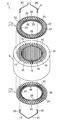
- FIG. 2 is an exploded perspective view showing the configuration of the stator according to the first embodiment.
- FIG. 3 is a cross-sectional view showing a main part of the stator according to the first embodiment.
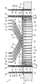
- FIG. 4 is a vertical cross-sectional view showing the configuration of one side of the stator in the axial direction at a portion corresponding to the line AA in FIG.
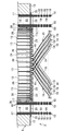
- FIG. 5 is a vertical cross-sectional view showing the configuration of the other side of the stator in the axial direction at the portion corresponding to the line AA in FIG.
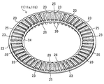
- FIG. 6 is a perspective view of the insulator according to the first embodiment as viewed from the front side.
- FIG. 7 is a perspective view seen from the back side of the insulator according to the first embodiment.
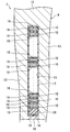
- FIG. 8 is a vertical cross-sectional view of the stator according to the second embodiment.
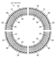
- FIG. 9 is a plan view of the insulator
- Embodiment 1 The first embodiment will be described.
- the motor (1) is used, for example, in a compressor of an air conditioner or an automobile.
- the motor (1) is an embedded magnet synchronous motor (IPMSM: Interior Permanent Magnet Synchronous Motor).
- IPMSM Interior Permanent Magnet Synchronous Motor
- the motor (1) includes a rotor (2) and a stator (3).
- the motor (1) is composed of an adduction type (inner rotor type) motor.
- the axial direction is a direction along the center line of the stator (stator core) and means the direction of the axial center of the drive shaft.
- the circumferential direction means the direction around the axis of the drive shaft.
- the radial direction means a direction orthogonal to the axis of the drive shaft.
- the outer peripheral side means a side farther from the axis of the drive shaft.
- the inner peripheral side means a side closer to the axis of the drive shaft.
- the vertical cross section means a cross section along the axial direction.
- the cross section means a cross section orthogonal to the axial direction.
- the rotor (2) includes one rotor core (4) and a plurality of permanent magnets (5).
- the rotor core (4) is configured to be substantially cylindrical.
- the rotor core (4) is a so-called laminated core.
- the rotor core (4) is formed by laminating a large number of annular electromagnetic steel sheets punched by a press working machine in the axial direction.
- the rotor core (4) may be made of, for example, a silicon steel plate or a dust core.
- a shaft hole (6) penetrating in the axial direction is formed in the center of the rotor core (4).
- a drive shaft (7) for transmitting a rotational force is inserted in the shaft hole (6).
- the drive shaft (7) is fixed to the rotor core (4) by a tight fit (eg, shrink fit).
- the axis of the rotor core (4) that is, the axis of the rotor (2)
- the axis of the drive shaft (7) are coaxial.
- a plurality of magnet slots (8) penetrating in the axial direction are formed on the outer peripheral side of the rotor core (4). These plurality of magnet slots (8) are arranged at predetermined intervals from each other in the circumferential direction of the rotor core (4).
- the magnet slot (8) is a hole for accommodating a permanent magnet (5).
- the shape of the magnet slot (8) is defined so that a gap is created as needed while the permanent magnet (5) is housed.
- a plate-shaped permanent magnet (5) is embedded in each magnet slot (8).
- six permanent magnets (5) are provided and the number of poles is six.
- the permanent magnet (5) for example, a sintered magnet such as a rare earth magnet containing a rare earth element, a ferrite magnet, a bond magnet obtained by crushing a magnet such as a ferrite magnet and kneading it into rubber or synthetic resin is used.
- the rotor (2) is rotatably attached to the stator (3).
- the rotor (2) is a magnet torque generated by the attractive force and the repulsive force generated by the magnetic pole of the permanent magnet (5) and the rotating magnetic field generated in the stator (3), and the rotor (2) generated by the rotating magnetic field of the stator (3). It rotates with the drive shaft (7) due to the relaxation torque generated by the suction force with the salient pole.
- the stator (3) includes one stator core (9), a plurality of stator windings (10), and a pair of insulators (11a, 11b).
- the stator core (9) is configured to have a substantially cylindrical shape.
- the stator core (9) is a so-called laminated core.
- the stator core (9) is formed by laminating a large number of annular electromagnetic steel sheets punched by a press working machine in the axial direction.
- the stator core (9) may be made of, for example, a silicon steel plate or a dust core.
- the stator core (9) is formed in a shape like an internal gear.
- the stator core (9) is provided with one back yoke (12) and a plurality of teeth (13).
- the back yoke (12) is an annular portion in a plan view on the outer peripheral side of the stator core (9).
- the tooth (13) is a portion protruding inward in the radial direction from the back yoke (12). These teeth (13) are arranged at a predetermined pitch in the circumferential direction of the stator core (9). In the example shown in FIG. 1, 48 teeth (13) are provided.
- brim portions (14) overhanging on both sides of the stator core (9) in the circumferential direction are provided at the inner peripheral end of each tooth (13).
- the brim portion (14) is formed over the entire axial direction of the teeth (13).
- the inner peripheral surfaces of the teeth (13) and the brim (14) form the inner peripheral surface of the stator core (9), and a predetermined distance (air) from the outer peripheral surface (cylindrical surface) of the rotor (2). They are facing each other with a gap).
- a winding slot (15) is provided between the teeth (13) adjacent to each other.
- the winding slot (15) is a space in which the stator winding (10) is accommodated.
- 48 winding slots (15) are provided.
- Each winding slot (15) has a so-called semi-closed structure, and is opened from between adjacent brim portions (14) to the inner peripheral side. As shown in FIGS. 4 and 5, a slit-shaped opening (16) is formed between the adjacent brim portions (14).
- Each winding slot (15) is provided with resin insulating paper (17).
- the insulating paper (17) is wound along the inner peripheral surface of the winding slot (15) and is arranged between the inner peripheral surface of the winding slot (15) and the stator winding (10). ing.
- the insulating paper (17) is formed of an insulating material such as polyethylene terephthalate (PET) or aramid fiber.
- both ends of the insulating paper (17) in the winding direction are overlapped on the inner peripheral side of the winding slot (15), and an opening (16) between adjacent brims (14) is provided. It is located in the place corresponding to.
- the insulating paper (17) serves to electrically insulate the inner peripheral surface of the winding slot (15) of the stator core (9) from the stator winding (10).
- the stator winding (10) is wound around the teeth (13) in a segmented distributed winding.
- the stator windings (10) of each phase are wound around the teeth (13) across a plurality of winding slots (15) and intersect and overlap the stator windings (10) of the other phase.
- an electromagnet is formed by the stator windings (10) of each of these phases.
- the stator windings (10) of each phase are configured by using a plurality of segment conductors (18) and joining the ends of different segment conductors (18).
- the segment conductor (18) is a flat wire that has been bent into a U shape. Copper wire is used for the flat wire.
- This segment conductor (18) is covered with a resin insulating coating (19).
- the insulating coating (19) is formed of, for example, polyetheretherketone (PEEK) or the like.
- the segment conductor (18) has a pair of legs (20) having a linearly formed portion and a crossover portion (21) connecting the pair of legs (20).
- the pair of legs (20) are plugged into different winding slots (15).
- a plurality of legs (20) of the segment conductors (18) are arranged so as to form a line in the radial direction.
- the same winding slot (15) may accommodate the legs (20) of the segment conductors (18) that make up the out-of-phase stator windings (10).
- Both ends of the segment conductor (18) are exposed from the insulating coating (19) (see FIG. 4).
- the ends of different segment conductors (18) protruding from the opposite side of the winding slot (15) from the insertion side are twisted together and joined by welding.
- the stator windings (10) of each phase are configured in a predetermined pattern by a combination of such a plurality of segment conductors (18).
- the stator windings (10) of each of these phases are wound around the teeth (13) via insulators (11a, 11b).
- the insulators (11a, 11b) include a first insulator (11a) and a second insulator (11b).
- the first insulator (11a) is arranged on one end face of the stator core (9) in the axial direction.
- the second insulator (11b) is arranged on the other end face of the stator core (9) in the axial direction.
- the stator core (9) is sandwiched from both sides in the axial direction by a first insulator (11a) and a second insulator (11b).
- An insulator (11) having the same configuration is used for both the first insulator (11a) and the second insulator (11b).
- the insulator (11) is a resin stator part, which is an annular integrally molded product.
- the insulator (11) is formed of, for example, a liquid crystal polymer (LCP), polybutylene terephthalate (PBT), or the like.
- the insulator (11) has one outer ring portion (22), a plurality of winding body portions (23), and one inner ring portion (24).
- the outer ring portion (22), the plurality of winding body portions (23), and the inner ring portion (24) are integrally molded.
- the outer ring portion (22) is an annular portion forming the outer peripheral portion of the insulator (11), which is formed to have a diameter larger than that of the inner ring portion (24).
- the inner ring portion (24) is an annular portion forming an inner peripheral portion of the insulator (11), which is formed to have a smaller diameter than the outer ring portion (22).
- the plurality of winding body portions (23) are arranged radially at intervals in the circumferential direction of the insulator (11), and connect the outer ring portion (22) and the inner ring portion (24) in the radial direction.
- the number of winding body parts (23) corresponding to the teeth (13) of the stator core (9) is provided.
- 48 winding cylinders (23) are provided.
- the winding body portion (23) has a shape that rises to the front side of the insulator (11) with respect to the outer ring portion (22) and the inner ring portion (24).
- the width of the winding body portion (23) in the circumferential direction is substantially the same as the width of the teeth (13) of the stator core (9) in the circumferential direction.
- the width of the winding body portion (23) in the circumferential direction becomes wider toward the outer peripheral side in accordance with the shape of the teeth (13).
- the ends of the insulator (11) located on the front side of the insulator (11) on both sides in the circumferential direction of the winding body (23) are formed in a curved shape with rounded edges so as not to make corners.
- the curved portion of the winding body portion (23) is a portion in contact with or close to the crossover portion (21) of the segment conductor (18).
- the curved portion of the winding body portion (23) is a portion in contact with or close to the leg portion (20) of the segment conductor (18).
- an insertion hole (25) through which the segment conductor (18) is inserted is opened between the adjacent winding cylinders (23).
- the number of insertion holes (25) corresponding to the winding slots (15) of the stator core (9) is provided.
- 48 insertion holes (25) are provided.
- the circumferential width of the insertion hole (25) is substantially the same as the circumferential width of the winding slot (15) of the stator core (9).
- a plurality of insertion portions (26) are integrally provided in the inner ring portion (24).
- Each of the plurality of insertion portions (26) is a portion protruding from the inner ring portion (24) to the back side of the insulator (11).
- the insertion portion (26) is located on the inner peripheral side of the insertion hole (25) between the adjacent winding cylinder portions (23) in the inner ring portion (24).
- the first insulator (11a) is arranged on the side where the segment conductor (18) is inserted with respect to the stator core (9), and is located on the same side as the crossover portion (21) of the segment conductor (18).
- the body portion (23) of the first insulator (11a) is arranged between the teeth (13) of the stator core (9) and the crossover portion (21) of the segment conductor (18).
- the insertion hole (25) of the first insulator (11a) is arranged at a location corresponding to the winding slot (15) of the stator core (9).
- the inner ring portion (24) of the first insulator (11a) is arranged along the brim portion (14) at the tip of the teeth (13) of the stator core (9).
- the insertion portion (26) of the first insulator (11a) is inserted from the open end in the axial direction with respect to the winding slot (15).
- the second insulator (11b) is arranged on the side where the legs (20) of different segment conductors (18) are joined to each other with respect to the stator core (9), and is located on the same side as the end of the segment conductor (18). are doing.
- the body portion (23) of the second insulator (11b) is arranged between the teeth (13) of the stator core (9) and the bent portion on the joint side of the segment conductor (18).
- the insertion hole (25) of the second insulator (11b) is arranged at a location corresponding to the winding slot (15) of the stator core (9).
- the inner ring portion (24) of the second insulator (11b) is arranged along the brim portion (14) at the tip of the teeth (13) of the stator core (9).
- the insertion portion (26) of the second insulator (11b) is inserted from the open end in the axial direction with respect to the winding slot (15).
- the insertion portion (26) of the first insulator (11a) and the insertion portion (26) of the second insulator (11b) are each a segment conductor housed in the winding slot (15). It is arranged on the inner peripheral side of the leg (20) located on the innermost peripheral side in the group of the legs (20) of (18). That is, these insertion portions (26) are interposed between the group of legs (20) of the segment conductor (18) and the brim portion (14) of the stator core (9) in the winding slot (15). There is.
- the insertion portion (26) of the first insulator (11a) and the insertion portion (26) of the second insulator (11b) partially block the opening (16) between the adjacent brim portions (14). (See FIGS. 4 and 5).
- the stator windings (10) are moved closer to the outer peripheral side of the winding slot (15) by the insertion portion (26) of the first insulator (11a) and the insertion portion (26) of the second insulator (11b). It is fixed in place.
- the insertion portion (26) of the first insulator (11a) and the insertion portion (26) of the second insulator (11b) are the legs (18) of the segment conductor (18) housed in the winding slot (15), respectively. It is caught inside the insulating paper (17) together with the group of 20). The insulating paper (17) is sandwiched between the insertion portion (26) of the insulator (11) and the inner peripheral surface of the winding slot (15).
- the insertion part (26) of the first insulator (11a) and the insertion part (26) of the second insulator (11b) eliminate the rattling of the segment conductor (18) in the winding slot (15).
- the segment conductor (18) plays a role of restraining the movement of the winding slot (15) by preventing it from moving toward the inner circumference side.
- these insertion portions (26) also have functions such as suppressing the magnetic imbalance of the teeth (13).
- the first insulator (11a) and the second insulator (11b) are provided on both end faces in the axial direction of the stator core (9) before the stator winding (15) is provided on the stator core (9). ) And set. After that, a plurality of segment conductors (18) are inserted into the winding slot (15) of the stator core (9) into which the insulating paper (17) is inserted in advance, and the first insulator (11a) and the second insulator (11b) are inserted. Plug in through. At this time, the crossover portion (21) of the segment conductor (18) is likely to bend.
- the segment conductor (18) is set on the stator core (9) by pulling the end of the segment conductor (18) that protrudes from the side opposite to the insertion side of the winding slot (15). Then, the ends protruding from the winding slot (15) of the predetermined segment conductor (18) are twisted and welded to each other. The segment conductor (18) is bent when its ends are twisted together with the other segment conductor (18).
- the first insulator (11a) When the segment conductor (18) is installed on the stator core (9), the first insulator (11a) receives the crossover portion (21) side of the segment conductor (18) by the winding body portion (23). It functions as a positioning member that determines the positional relationship of the segment conductor (18) with respect to the stator core (9) in the axial direction. This first insulator (11a) contributes to reducing the rattling of the stator winding (10).
- the second insulator (11b) receives the bent legs (20) of the segment conductor (18) at the winding body (23) when twisting the ends of the segment conductor (18) together. It functions as a spacer interposed between the joint between the segment conductors (18) and the stator core (9).
- the second insulator (11b) like the first insulator (11a), contributes to reducing the rattling of the stator winding (10).
- the stator (3) of the first embodiment includes a first insulator (11a) and a second insulator (11b) arranged on both end faces in the axial direction of the stator core (9).
- Each of the first insulator (11a) and the second insulator (11b) is a resin member, and a plurality of winding body portions (23) and a plurality of insertion portions (26) are integrally formed. ..
- the winding body portion (23) of the first insulator (11a) is arranged between the stator core (9) and the crossover portion (21) of the segment conductor (18), and the crossover portion (21) of the segment conductor (18) is arranged. 21) Received the side.
- the winding body portion (23) of the first insulator (11a) functions as a positioning member that determines the positional relationship of the segment conductor (18) with respect to the stator core (9) in the axial direction.
- the accuracy of positioning of the segment conductor (18) with respect to the stator core (9) in the insertion direction can be improved.
- the insulation distance between the end face of the stator core (9) and the stator winding (10) can be suitably secured on the side where the first insulator (11a) is arranged.
- the allowance of the segment conductor (18) from the winding slot (15) can be stabilized.
- the length of the segment conductor (18) can be designed to be short.
- copper loss in the individual segment conductors (18) can be reduced, and the efficiency of generating a rotating magnetic field by the stator windings (10) can be improved.
- the clearance between the motor (1) including the stator (3) and the casing accommodating the motor (1) can be reduced, which contributes to the reduction of product size.
- the winding body portion (23) of the second insulator (11b) is arranged between the joint portion between the segment conductors (18) and the stator core (9), and the bent leg portion (20) of the segment conductor (18) is arranged. ) Is received at the winding body (23).
- the segment conductor (18) is damaged by interfering with the end face of the stator core (9) in the bending process when the ends of the segment conductor (18) are joined to each other. Can be prevented. Thereby, the quality of the stator winding (10) can be improved.
- the winding body portion (23) of the second insulator (11b) functions as a spacer interposed between the joint portion between the segment conductors (18) and the stator core (9).
- the insulation distance between the end face of the stator core (9) and the stator winding (10) can be suitably secured on the side where the second insulator (11b) is arranged.
- both the insertion portion (26) of the first insulator (11a) and the insertion portion (26) of the second insulator (11b) are segment conductors (26) located on the innermost peripheral side in the winding slot (15). It is located on the inner circumference side of the leg (20) of 18). Thereby, the movement of the segment conductor (18) in the winding slot (15) can be suppressed by both the insertion portions (26) of the first insulator (11a) and the second insulator (11b).
- the stator winding (10) is fixed at a predetermined position in the winding slot (15), so that the opening (16) provided on the inner peripheral side of the winding slot (15) is provided. ) Can be prevented from popping out.
- the insertion portion (26) of the first insulator (11a) and the second insulator (11b) are inserted.
- the insulation distance between the stator winding (10) and the rotor (2) is secured by the portion (26) and the insulating paper (17). Further, it is possible to reduce the eddy current generated by interlinking the high-frequency magnetic flux generated between the teeth (13) with the stator winding (10). This makes it possible to prevent abnormal heat generation of the stator winding (10) due to eddy current.
- stator winding (10) When the leakage flux from the tip of the teeth (13) interlinks with the stator winding (10), a phenomenon occurs in which the current density of each stator winding (10) differs due to the induced electromotive voltage difference. The greater the amount of leakage flux interlinking with the stator winding (10), the greater the loss of the motor (1).
- stator (3) of the first embodiment the stator windings (10) are fixed closer to the outer peripheral side of the winding slot (15), so that the leakage flux from the tip of the teeth (13) Since the amount of interlinkage with the stator winding (10) is reduced, the loss of the motor (1) can be reduced.
- the plurality of insertion portions (26) in the first insulator (11a) have a positional relationship that surrounds the group of brim portions (14) on the outer peripheral side with respect to the stator core (9) as a whole. According to this, when the first insulator (11a) is attached to the stator core (9), the first insulator (11a) can be fixed to the stator core (9), so that the stator winding (10) can be fixed to the stator core (9). It is advantageous for improving workability when the coil is provided. In this regard, the same effect can be obtained with the second insulator (11b).
- a rod-shaped resin part called a wedge is attached to each of a plurality of winding slots (15) on the innermost side of the leg portion (20) of the segment conductor (18). It is known that the structure is inserted between the brim portion (14) and the insertion portion (26) of the first insulator (11a) and the second insulator (11b).
- the wedge can be omitted and the stator (3).
- the number of parts can be reduced.
- the first insulator (11a) and the second insulator (11b) are annular integrally molded products, they can be easily attached to the stator core (9) in the fabrication of the stator (3). Then, simply by attaching the first insulator (11a) and the second insulator (11b) to the stator core (9), the work of inserting the wedge into the winding slot (15) can be eliminated, so that the stator ( Workability in the production of 3) can be improved.
- the insulating paper (17) is wound with the insertion portion (26) of the first insulator (11a) and the insertion portion (26) of the second insulator (11b). It is sandwiched by the inner peripheral surface of the slot (15).
- the insulating paper (17) can be fixed in the winding slot (15) with respect to the stator core (9).
- the workability is good, and the stator (3) can be stably manufactured.
- segment conductor (18) is covered with a resin insulating film (19).
- insulation is ensured around the segment conductor (18), and the segment conductor (18) constituting the different-phase stator winding (10) can be arranged in the same winding slot (15).
- the portion of the winding body portion (23) of the first insulator (11a) that is in contact with or close to the crossover portion (21) of the segment conductor (18) is formed in a curved shape.
- the portion of the winding body portion (23) of the second insulator (11b) that is in contact with or close to the leg portion (20) of the segment conductor (18) is formed in a curved shape.
- the segment conductor (18) becomes the winding body portion (23) of the second insulator (11b) in the bending process when the ends of the segment conductors (18) are joined to each other. It can be prevented from being damaged even if it interferes.
- Embodiment 2 The second embodiment will be described.
- the motor (1) of the second embodiment is the motor (1) of the first embodiment in which the shapes of the first insulator (11a) and the second insulator (11b) of the stator (3) are changed.
- the stator (3) included in the motor (1) of the second embodiment will be described as being different from the stator (3) of the first embodiment.
- each insertion portion (26) of the first insulator (11a) is formed to have a length of about half the axial length of the winding slot (15) of the stator core (9).
- each insertion portion (26) of the second insulator (11b) is also formed to have a length of about half of the axial length of the winding slot (15) of the stator core (9).
- the insertion portion (26) of the first insulator (11a) and the insertion portion (26) of the second insulator (11b) are located at intermediate positions in the length direction of the winding slot (15) and are mutually axially positioned. It is butted.
- the shape of the abutting surface between the insertion portion (26) of the first insulator (11a) and the insertion portion (26) of the second insulator (11b) is a plane orthogonal to the axial direction as shown in FIG. , Various shapes such as an inclined surface that is inclined in both the axial direction and the radial direction can be adopted.
- the leg portion (20) of the segment conductor (18) located on the innermost peripheral side in the winding slot (15) is the first on the inner peripheral side of the stator core (9).
- the insertion part (26) of the insulator (11a) and the insertion part (26) of the second insulator (11b) cover the entire winding slot (15) in the length direction.
- the above-described first and second embodiments may have the following configurations.
- the insulator (11) used as the first insulator (11a) and the second insulator (11b) may include a plurality of arc-shaped divided bodies (50).
- the plurality of divided bodies (50) include an outer ring piece (51) constituting the outer ring (22), an inner ring piece (52) constituting the inner ring (24), a winding body portion (23), and an insert. It has a part (26).
- the plurality of divided bodies (50) are combined with each other to form an annular shape as a whole.
- Adjacent split pieces (50) may be connected to each other by a fitting structure.
- the type in which the annular insulator (11) is divided into four is illustrated, but the number of divisions of the insulator (11) may be two or any number of divisions is adopted. It is possible to do.
- the cumulative tolerance (stacking tolerance) of each split body (50) can be suppressed as compared with the cumulative tolerance of the insulator (11) made of an annular integrally molded product. Therefore, the insulator (11) can be easily attached to the stator core (9).
- the insertion portion (26) of the first insulator (11a) and the insertion portion (26) of the second insulator (11b) are fitted at the tip portions that abut each other. It may be like this. Further, there is a gap between the insertion portion (26) of the first insulator (11a) and the insertion portion (26) of the second insulator (11b) in the middle in the axial direction of the winding slot (15). It may be provided at a length facing each other. The length of the insertion portion (26) can be set to any length.
- the segment conductor (18) constituting the stator winding (10) does not have to be provided with the insulating coating (19).
- the above-mentioned effect that the insulation distance between the end face of the stator core (9) and the stator winding (10) can be secured by the first insulator (11a) and the second insulator (11b) is particularly effective.
- the insulator (11) provided on the stator core (9) may be only the first insulator (11a).
- the winding slot (15) of the stator core (9) may have an open structure in which the tooth (13) is not provided with the brim portion (14), and the inner peripheral side of the stator core (9) may be provided.
- a closed structure in which an opening (16) is not formed may be used.
- the present disclosure is useful for the stator.
Landscapes
- Engineering & Computer Science (AREA)
- Power Engineering (AREA)
- Insulation, Fastening Of Motor, Generator Windings (AREA)
- Windings For Motors And Generators (AREA)
Abstract
ステータ(3)において、セグメント導体(18)は、スロット(15)に差し込まれる一対の脚部(20)と、一対の脚部(20)を繋ぐ渡り線部(21)とを有する。ステータ(3)は、ステータコア(9)とセグメント導体(18)の渡り線部(21)との間に配置される巻胴部(23)と、ステータコア(9)のスロット(15)内においてセグメント導体(18)の脚部(20)よりも内側に配置される挿入部(26)とが一体成形されたインシュレータ(11a)を備える。
Description
本開示は、ステータに関するものである。
従来から、モータには、複数のスロットが周方向に設けられた円筒状のステータコアと、ステータコアの軸方向における端面に配置されたインシュレータとを備えるステータが用いられている。例えば、特許文献1には、セグメント方式で設けられたステータ巻線を有し、このステータ巻線を、インシュレータであるコイル固定部材を用いて固定したステータが開示されている。
セグメント方式のステータ巻線は、複数のセグメント導体を用いて構成されている。セグメント導体は、直線状に延びる一対の脚部と脚部同士を繋ぐ渡り線部とを有する略U字形状の平角線である。セグメント導体における一対の脚部は、ステータコアの異なるスロットに差し込まれている。異なるセグメント導体の脚部におけるスロットの差し込み側とは反対側から突出した端部同士は互いに接合されている。
特許文献1に開示のステータでは、スロットを形成する隣り合うティースの各先端部にスロットの内方へ突出したツバ部が設けられている。コイル固定部材は、スロットに配置される複数のセグメント導体の脚部のうちステータコアの径方向における最も内側に配置された脚部とツバ部との間に形成される隙間を覆うように設置されている。このコイル固定部材は、当該隙間に挿入されるスロット挿入部を有し、スロット挿入部によりスロット内でのセグメント導体の移動を抑止する。
特許文献1のようにセグメント方式でステータ巻線を設ける場合、セグメント導体の脚部をスロットに差し込んだ後、セグメント導体の端部同士を溶接などで接合する必要がある。このため、ステータコアに対するセグメント導体の位置決めの精度が重要となる。セグメント導体の脚部をスロットに差し込むときには、渡り線部が撓みやすいため、セグメント導体におけるスロットの差し込み側とは反対側から突出した端部を引っ張ることが行われている。
しかし、ステータコアとセグメント導体との位置関係を、セグメント導体のスロットへの差し込み方向において固定できない。そのため、セグメント導体の端部を引っ張った際、セグメント導体がステータコアにおけるスロットの開放端のエッジと干渉することによって傷付き、ステータ巻線の品質が悪化するおそれがある。また、セグメント導体のスロットからの出代が安定しないことから、セグメント導体の端部同士を接合するときの作業性が悪く、セグメント導体同士の接合の品質が悪化することが懸念される。
本開示の目的は、スロット内でのセグメント導体の移動を抑止し、且つステータコアに対するセグメント導体の差し込み方向における位置決めの精度を向上させることにある。
本開示の第1の態様は、複数のスロットが設けられた筒状のステータコアと、該ステータコアに取り付けられるセグメント導体とを備えたステータを対象とする。第1の態様に係るステータでは、前記セグメント導体は、前記スロットに差し込まれる複数の脚部と、異なる前記スロットに差し込まれる2つの前記脚部を繋ぐ渡り線部とを有する。前記ステータコアと前記セグメント導体の渡り線部との間に配置される巻胴部と、前記ステータコアの前記スロット内において前記セグメント導体よりも内側に配置される挿入部とが一体成形された樹脂製のインシュレータをさらに備える。
第1の態様では、インシュレータの巻胴部が、ステータコアとセグメント導体の渡り線部との間に配置される。また、インシュレータの挿入部が、ステータコアのスロット内においてセグメント導体の脚部よりも内側に配置される。これにより、スロット内でのセグメント導体の移動を抑止し、且つステータコアに対するセグメント導体の差し込み方向における位置決めの精度を向上させることができる。また、このようなインシュレータは、ステータ巻線のがたつきを低減するのに寄与する。
本開示の第2の態様は、第1の態様のステータにおいて、前記スロットに、当該スロットの内周面と当該スロットに差し込まれる前記セグメント導体の脚部との間に絶縁紙が設けられている。前記絶縁紙は、前記インシュレータの挿入部と当該スロットの内周面との間に挟み込まれている。
第2の態様では、絶縁紙がインシュレータの挿入部とスロットの内周面とにより固定される。これにより、ステータの作製において、スロットに対し絶縁紙を固定した状態でセグメント導体を差し込むことが可能になるので、ステータコアにステータ巻線を設ける際の作業性が良く、ステータを安定して作製することができる。
本開示の第3の態様は、第1または第2の態様のステータにおいて、前記セグメント導体が、樹脂製の絶縁被膜によって覆われている。
第3の態様では、樹脂製の絶縁被膜付きのセグメント導体が、ステータ巻線に用いられている。これにより、セグメント導体の周囲に絶縁性を確保し、同じスロットに異相のステータ巻線を構成するセグメント導体を配置することができる。
本開示の第4の態様は、第1~第3の態様のいずれか1つのステータにおいて、前記インシュレータの巻胴部のうち前記セグメント導体の渡り線部と接触または近接する部位が、湾曲形状に形成されている。
第4の態様では、インシュレータの巻胴部の湾曲形状に形成された部位が、セグメント導体の渡り線部と接触または近接する。これにより、セグメント導体がインシュレータの巻胴部に強く干渉するのを抑制できる。
本開示の第5の態様は、第1~第4の態様のいずれか1つのステータにおいて、前記ステータコアの中心線に沿う軸方向における一方側の端面に、前記インシュレータである第1のインシュレータが配置されている。前記ステータコアの前記軸方向における他方側の端面には、前記インシュレータと同じ構成を有する第2のインシュレータが配置されている。
第5の態様では、第2のインシュレータが、第1のインシュレータと同じ構成を有し、ステータコアの軸方向におけるセグメント導体の挿入側とは反対側の端面に配置されている。これにより、ステータの作製において、セグメント導体の端部同士を接合するときの折り曲げ加工で、セグメント導体がステータコアに接触することによる傷付きを防止することができる。また、第2のインシュレータがステータ巻線とステータコアとの間でスペーサとして機能し、セグメント導体の端部同士を接合するときの折り曲げ加工時に位置決めを行えるので、第1のインシュレータと同様に、ステータ巻線のがたつきを低減するのに寄与する。
本開示の第6の態様は、第5の態様のステータにおいて、前記第1のインシュレータの挿入部と、前記第2のインシュレータの挿入部とは、前記ステータコアの軸方向において互いに突き合わせられている。
第6の態様では、セグメント導体の脚部が、ステータコアの内周側で、第1のインシュレータの挿入部と第2のインシュレータの挿入部とにより、スロットの長さ方向における全体に亘って覆われる。これにより、セグメント導体の脚部がその中程で撓るように変形しようとしても、当該脚部の変形を規制して、スロット内でのセグメント導体の移動を好適に防止することができる。
本開示の第7の態様は、第1~第6の態様のいずれか1つのステータにおいて、前記インシュレータが、環状の一体成形物である。
第7の態様では、インシュレータとして環状の一体成形物を用いている。これによれば、ステータの作製において、ステータコアにインシュレータを簡単に取り付けることができる。よって、ステータを組み立てる際の作業性を向上させることができる。
本開示の第8の態様は、第1~第6の態様のいずれか1つのステータにおいて、前記インシュレータが、前記巻胴部および前記挿入部を有する円弧状の分割体を複数備え、該複数の分割体を組み合わせて環状に構成されている。
第8の態様では、インシュレータとして、互いに組み合わせられることで環状をなす複数の分割体を用いている。これによれば、個々の分割体の累積公差(積み上げ公差)を環状の一体成形物からなるインシュレータの累積公差に比べて抑えることができるので、インシュレータをステータコアに取り付けやすくすることができる。
《実施形態1》
実施形態1について説明する。
実施形態1について説明する。
モータ(1)は、例えば、空気調和装置の圧縮機や自動車などに用いられる。モータ(1)は、埋込磁石同期型のモータ(IPMSM:Interior Permanent Magnet Synchronous Motor)である。モータ(1)は、図1に示すように、ロータ(2)と、ステータ(3)とを備える。モータ(1)は、内転形(インナーロータ形)のモータに構成されている。
なお、以下の説明において、軸方向とは、ステータ(ステータコア)の中心線に沿う方向であって、駆動軸の軸心の方向を意味する。周方向とは、駆動軸の軸心周りの方向を意味する。径方向とは、駆動軸の軸心と直交する方向を意味する。外周側とは、駆動軸の軸心からより遠い側と意味する。内周側とは、駆動軸の軸心により近い側を意味する。また、縦断面とは、軸方向に沿った断面を意味する。横断面とは、軸方向に直交する断面を意味する。
-ロータ-
ロータ(2)は、1つのロータコア(4)と、複数の永久磁石(5)とを備える。
ロータ(2)は、1つのロータコア(4)と、複数の永久磁石(5)とを備える。
ロータコア(4)は、略円筒状に構成されている。ロータコア(4)は、いわゆる積層コアである。具体的には、ロータコア(4)は、プレス加工機により打ち抜き加工された円環状の電磁鋼板が、軸方向に多数枚積層されて構成されている。なお、ロータコア(4)は、例えば、シリコン鋼板や圧粉磁心によって構成されていてもよい。
ロータコア(4)の中心には、軸方向に貫通する軸孔(6)が形成されている。軸孔(6)には、回転力を伝達するための駆動軸(7)が挿入されている。駆動軸(7)は、締まり嵌め(例えば焼き嵌め)によってロータコア(4)に固定されている。ロータコア(4)の軸心(すなわちロータ(2)の軸心)と駆動軸(7)の軸心とは同軸上に存在する。
ロータコア(4)の外周側には、軸方向に貫通する磁石スロット(8)が複数形成されている。これら複数の磁石スロット(8)は、ロータコア(4)の周方向に互いに所定の間隔をあけて配置されている。磁石スロット(8)は、永久磁石(5)を収容する孔である。磁石スロット(8)の形状は、永久磁石(5)を収容した状態で、必要に応じて隙間ができるように定められている。
各磁石スロット(8)には、板状の永久磁石(5)が埋設されている。図1に示す例では、永久磁石(5)が6つ設けられ、極数が6である。永久磁石(5)には、例えば、希土類元素を含む希土類磁石といった焼結磁石やフェライト磁石、フェライト磁石などの磁石を砕いてゴムや合成樹脂に練り込んだボンド磁石などが用いられる。
ロータ(2)は、ステータ(3)に対して回転可能に装着されている。ロータ(2)は、永久磁石(5)の磁極とステータ(3)に生じる回転磁界とによる吸引力および反発力によって発生するマグネットトルクと、ステータ(3)の回転磁界による当該ロータ(2)の突極との吸引力によって生じるリラクタンストルクとにより、駆動軸(7)と共に回転する。
-ステータ-
ステータ(3)は、図1および図2に示すように、1つのステータコア(9)と、複数のステータ巻線(10)と、一対のインシュレータ(11a,11b)とを備える。
ステータ(3)は、図1および図2に示すように、1つのステータコア(9)と、複数のステータ巻線(10)と、一対のインシュレータ(11a,11b)とを備える。
ステータコア(9)は、略円筒状に構成されている。ステータコア(9)は、いわゆる積層コアである。具体的には、ステータコア(9)は、プレス加工機により打ち抜き加工された環状の電磁鋼板が、軸方向に多数枚積層されて構成されている。なお、ステータコア(9)は、例えば、シリコン鋼板や圧粉磁心によって構成されていてもよい。ステータコア(9)は、内歯歯車のような形状に形成されている。
ステータコア(9)は、1つのバックヨーク(12)と、複数のティース(13)とを備える。バックヨーク(12)は、ステータコア(9)の外周側の、平面視で環状の部分である。ティース(13)は、バックヨーク(12)から径方向における内側に向けて突き出た部分である。これらティース(13)は、ステータコア(9)の周方向に所定のピッチで配置されている。図1に示す例では、48個のティース(13)が設けられている。
各ティース(13)の内周側の端部には、図3に示すように、ステータコア(9)の周方向における両側に張り出したツバ部(14)が設けられている。ツバ部(14)は、ティース(13)の軸方向における全体に亘って形成されている。ティース(13)およびツバ部(14)の内周側の面は、ステータコア(9)の内周面を構成し、ロータ(2)の外周面(円筒面)との間に所定の距離(エアギャップ)をあけて対向している。
互いに隣り合うティース(13)の間には、巻線スロット(15)が設けられている。巻線スロット(15)は、ステータ巻線(10)が収容される空間である。図1に示す例では、48個の巻線スロット(15)が設けられている。各巻線スロット(15)は、いわゆるセミクローズド構造とされ、隣り合うツバ部(14)の間から内周側に開放されている。隣り合うツバ部(14)の間には、図4および図5にも示すように、スリット状の開口(16)が形成されている。
各巻線スロット(15)には、樹脂製の絶縁紙(17)が設けられている。絶縁紙(17)は、巻線スロット(15)の内周面に沿うように巻かれた状態で、巻線スロット(15)の内周面とステータ巻線(10)との間に配置されている。絶縁紙(17)は、ポリエチレンテレフタレート(PET)やアラミド繊維などの絶縁材料によって形成されている。
図3に示す例では、絶縁紙(17)の巻き方向における両端部は、巻線スロット(15)の内周側で重ね合わせられて、隣り合うツバ部(14)の間の開口(16)に対応する箇所に位置している。絶縁紙(17)は、ステータコア(9)の巻線スロット(15)の内周面とステータ巻線(10)とを電気的に絶縁する役割を果たす。
ステータ巻線(10)は、セグメント方式の分布巻きでティース(13)に巻き付けられている。ステータ巻線(10)として、U相のステータ巻線と、V相のステータ巻線と、W相のステータ巻線とが設けられている。各相のステータ巻線(10)は、複数の巻線スロット(15)を跨いでティース(13)に巻き付けられ、他相のステータ巻線(10)と交差して重なり合っている。各ティース(13)には、これら各相のステータ巻線(10)により電磁石が構成されている。
各相のステータ巻線(10)は、セグメント導体(18)を複数用い、異なるセグメント導体(18)の端部同士を接合することで構成されている。セグメント導体(18)は、U字形状に折り曲げ加工された平角線である。平角線には、銅線が用いられている。このセグメント導体(18)は、樹脂製の絶縁被膜(19)によって覆われている。絶縁被膜(19)は、例えばポリエーテルエーテルケトン(PEEK)などによって形成されている。
セグメント導体(18)は、直線状に形成された部分を有する一対の脚部(20)と、一対の脚部(20)を繋ぐ渡り線部(21)とを有する。一対の脚部(20)は、互いに異なる巻線スロット(15)に差し込まれている。各巻線スロット(15)には、セグメント導体(18)の脚部(20)が径方向に一列をなすように複数配置されている。同一の巻線スロット(15)に、異相のステータ巻線(10)を構成するセグメント導体(18)の脚部(20)が収容されることもあり得る。
セグメント導体(18)の両端部(各脚部(20)の先端部位)は、絶縁被膜(19)から露出している(図4参照)。異なるセグメント導体(18)における巻線スロット(15)の差し込み側とは反対側から突出した端部同士は、互いに捩り合わされて溶接により接合されている。各相のステータ巻線(10)は、そうした複数のセグメント導体(18)の組み合わせにより所定のパターンに構成されている。これら各相のステータ巻線(10)は、インシュレータ(11a,11b)を介してティース(13)に巻き付けられている。
インシュレータ(11a,11b)としては、第1のインシュレータ(11a)と、第2のインシュレータ(11b)とを備える。第1のインシュレータ(11a)は、ステータコア(9)の軸方向における一方側の端面に配置されている。第2のインシュレータ(11b)は、ステータコア(9)の軸方向における他方側の端面に配置されている。ステータコア(9)は、第1のインシュレータ(11a)と第2のインシュレータ(11b)とによって軸方向における両側から挟み込まれている。
第1のインシュレータ(11a)および第2のインシュレータ(11b)にはいずれも、同じ構成のインシュレータ(11)が用いられている。
図6および図7に示すように、インシュレータ(11)は、樹脂製のステータ部品であって、円環状の一体成型物である。インシュレータ(11)は、例えば、液晶ポリマー(LCP)やポリブチレンテレフタレート(PBT)などによって形成されている。インシュレータ(11)は、1つのアウタリング部(22)と、複数の巻胴部(23)と、1つのインナリング部(24)とを有する。アウタリング部(22)、複数の巻胴部(23)およびインナリング部(24)は一体に成形されている。
アウタリング部(22)は、インナリング部(24)よりも大径に形成された、インシュレータ(11)の外周部を構成する円環状の部分である。インナリング部(24)は、アウタリング部(22)よりも小径に形成された、インシュレータ(11)の内周部を構成する円環状の部分である。複数の巻胴部(23)は、インシュレータ(11)の周方向に互いに間隔をあけて放射状に配置され、アウタリング部(22)とインナリング部(24)とを径方向に繋いでいる。
巻胴部(23)は、ステータコア(9)のティース(13)に対応する数だけ設けられている。図6および図7に示す例では、48個の巻胴部(23)が設けられている。巻胴部(23)は、アウタリング部(22)およびインナリング部(24)に対してインシュレータ(11)の表側に隆起する形状とされている。巻胴部(23)の周方向における幅は、ステータコア(9)のティース(13)の周方向における幅と略同じである。
巻胴部(23)の周方向における幅は、ティース(13)の形状に合わせて外周側に向かって広くなっている。巻胴部(23)の周方向における両側でインシュレータ(11)の表側に位置する端部は、角が立たないように丸みを付けた湾曲形状に形成されている。第1のインシュレータ(11a)において、巻胴部(23)の当該湾曲形状とされた部位は、セグメン
ト導体(18)の渡り線部(21)と接触または近接する部位である。第2のインシュレータ(11b)において、巻胴部(23)の当該湾曲形状とされた部位は、セグメント導体(18)の脚部(20)と接触または近接する部位である。
ト導体(18)の渡り線部(21)と接触または近接する部位である。第2のインシュレータ(11b)において、巻胴部(23)の当該湾曲形状とされた部位は、セグメント導体(18)の脚部(20)と接触または近接する部位である。
インシュレータ(11)において、隣り合う巻胴部(23)の間には、セグメント導体(18)が挿通される挿通孔(25)が開口している。挿通孔(25)は、ステータコア(9)の巻線スロット(15)に対応する数だけ設けられている。図6および図7に示す例では、48個の挿通孔(25)が設けられている。挿通孔(25)の周方向における幅は、ステータコア(9)の巻線スロット(15)の周方向における幅と略同じである。
インナリング部(24)には、複数の挿入部(26)が一体に設けられている。複数の挿入部(26)はそれぞれ、インナリング部(24)からインシュレータ(11)の裏側に突き出した部分である。挿入部(26)は、インナリング部(24)において、隣り合う巻胴部(23)の間で挿通孔(25)の内周側に位置している。
第1のインシュレータ(11a)は、ステータコア(9)に対し、セグメント導体(18)を差し込む側に配置され、セグメント導体(18)の渡り線部(21)と同じ側に位置している。第1のインシュレータ(11a)の胴部(23)は、ステータコア(9)のティース(13)とセグメント導体(18)の渡り線部(21)との間に配置されている。
第1のインシュレータ(11a)の挿通孔(25)は、ステータコア(9)の巻線スロット(15)に対応する箇所に配置されている。第1のインシュレータ(11a)のインナリング部(24)は、ステータコア(9)のティース(13)先端部にあるツバ部(14)に沿って配置されている。そして、第1のインシュレータ(11a)の挿入部(26)は、巻線スロット(15)に対して軸方向における開放端から挿入されている。
第2のインシュレータ(11b)は、ステータコア(9)に対し、異なるセグメント導体(18)の脚部(20)同士を接合する側に配置され、セグメント導体(18)の端部と同じ側に位置している。第2のインシュレータ(11b)の胴部(23)は、ステータコア(9)のティース(13)とセグメント導体(18)の接合部側の折り曲げ部分との間に配置されている。
第2のインシュレータ(11b)の挿通孔(25)は、ステータコア(9)の巻線スロット(15)に対応する箇所に配置されている。第2のインシュレータ(11b)のインナリング部(24)は、ステータコア(9)のティース(13)先端部にあるツバ部(14)に沿って配置されている。そして、第2のインシュレータ(11b)の挿入部(26)は、巻線スロット(15)に対して軸方向における開放端から挿入されている。
図3に示すように、第1のインシュレータ(11a)の挿入部(26)と第2のインシュレータ(11b)の挿入部(26)とはそれぞれ、巻線スロット(15)に収容されたセグメント導体(18)の脚部(20)の群における最も内周側に位置する脚部(20)よりも内周側に配置されている。すなわち、それら挿入部(26)は、巻線スロット(15)内において、セグメント導体(18)の脚部(20)の群とステータコア(9)のツバ部(14)との間に介在している。
第1のインシュレータ(11a)の挿入部(26)と第2のインシュレータ(11b)の挿入部(26)とは、隣り合うツバ部(14)の間の開口(16)を部分的に塞いでいる(図4および図5参照)。ステータ巻線(10)は、それら第1のインシュレータ(11a)の挿入部(26)と第2のインシュレータ(11b)の挿入部(26)とにより、巻線スロット(15)の外周側に寄せて所定の位置に固定されている。
第1のインシュレータ(11a)の挿入部(26)と第2のインシュレータ(11b)の挿入部(26)とはそれぞれ、巻線スロット(15)に収容されたセグメント導体(18)の脚部(20)の群と共に絶縁紙(17)の内方に巻き込まれている。絶縁紙(17)は、インシュレータ(11)の挿入部(26)と巻線スロット(15)の内周面との間に挟み込まれている。
第1のインシュレータ(11a)の挿入部(26)と第2のインシュレータ(11b)の挿入部(26)とは、巻線スロット(15)内でのセグメント導体(18)のがたつきを無くし、セグメント導体(18)が巻線スロット(15)内で内周側に寄らないようにしてその移動を抑止する役割を担う。また、それら挿入部(26)は、ティース(13)の磁気的不平衡を抑制するなどの機能も有している。
ステータ(3)の作製においては、ステータコア(9)にステータ巻線(15)を設ける前に、ステータコア(9)の軸方向における両端面に第1のインシュレータ(11a)と第2のインシュレータ(11b)とをセットする。その後、複数のセグメント導体(18)を、予め絶縁紙(17)が挿入してあるステータコア(9)の巻線スロット(15)に第1のインシュレータ(11a)および第2のインシュレータ(11b)を介して差し込む。このとき、セグメント導体(18)の渡り線部(21)が撓みやすい。そのため、セグメント導体(18)における巻線スロット(15)の差し込み側とは反対側から突出した端部を引っ張って、セグメント導体(18)をステータコア(9)にセットする。そして、所定のセグメント導体(18)の巻線スロット(15)から突出した端部同士を互いに捩り合わせて溶接する。セグメント導体(18)は、他のセグメント導体(18)と端部を捩り合わせた際に折り曲げられる。
第1のインシュレータ(11a)は、ステータコア(9)にセグメント導体(18)を設置する際に、セグメント導体(18)の渡り線部(21)側を巻胴部(23)で受けることにより、ステータコア(9)に対するセグメント導体(18)の位置関係を軸方向において決める位置決め部材として機能する。この第1のインシュレータ(11a)は、ステータ巻線(10)のがたつきを低減するのに寄与する。
第2のインシュレータ(11b)は、セグメント導体(18)の端部同士を捩り合わせる際に、セグメント導体(18)の曲げられた脚部(20)を巻胴部(23)で受けることにより、セグメント導体(18)同士の接合部とステータコア(9)との間に介在されるスペーサとして機能する。この第2のインシュレータ(11b)は、第1のインシュレータ(11a)と同様に、ステータ巻線(10)のがたつきを低減するのに寄与する。
-実施形態1の効果-
この実施形態1のステータ(3)は、ステータコア(9)の軸方向における両端面に配置された第1のインシュレータ(11a)と第2のインシュレータ(11b)とを備えている。これら第1のインシュレータ(11a)および第2のインシュレータ(11b)はそれぞれ、樹脂製の部材であり、複数の巻胴部(23)と複数の挿入部(26)とが一体に成形されている。
この実施形態1のステータ(3)は、ステータコア(9)の軸方向における両端面に配置された第1のインシュレータ(11a)と第2のインシュレータ(11b)とを備えている。これら第1のインシュレータ(11a)および第2のインシュレータ(11b)はそれぞれ、樹脂製の部材であり、複数の巻胴部(23)と複数の挿入部(26)とが一体に成形されている。
第1のインシュレータ(11a)の巻胴部(23)は、ステータコア(9)とセグメント導体(18)の渡り線部(21)との間に配置され、セグメント導体(18)の渡り線部(21)側を受けている。そのことで、ステータ(3)の作製において、セグメント導体(18)をステータコア(9)に設置するために巻線スロット(15)から突出したセグメント導体(18)の端部を引っ張った際、セグメント導体(18)がステータコア(9)における巻線スロット(15)の開放端のエッジと干渉することによって傷付くのを防止することができる。これにより、ステータ巻線(10)の品質を高めることができる。
また、第1のインシュレータ(11a)の巻胴部(23)は、ステータコア(9)に対するセグメント導体(18)の位置関係を軸方向において決める位置決め部材として機能する。そのことで、ステータコア(9)に対するセグメント導体(18)の差し込み方向における位置決めの精度を向上させることができる。これにより、ステータコア(9)の端面とステータ巻線(10)との絶縁距離を第1のインシュレータ(11a)が配置される側で好適に確保することができる。また、セグメント導体(18)の巻線スロット(15)からの出代を安定させることができる。
セグメント導体(18)の巻線スロット(15)からの出代を安定させる手立てとしては、第1のインシュレータ(11a)を用いない場合、セグメント導体(18)の脚部(20)に調整代を設けて巻線スロット(15)からの突出した当該脚部(20)の余分を切除することで出代を合わせることが考えられる。しかし、個々のセグメント導体(18)が長くなるため、ステータ巻線(10)のコストアップを招く。この実施形態1のステータ(3)では、セグメント導体(18)の巻線スロット(15)からの出代を調整しなくて済むので、セグメント導体(18)同士を溶接する際の作業性を向上させることができる。また、セグメント導体(18)同士の接合の品質(溶接品質)を高めることができる。
さらに、ステータコア(9)に対するセグメント導体(18)の差し込み方向における位置決めの精度を向上することで、セグメント導体(18)の長さを短く設計することができる。これにより、個々のセグメント導体(18)での銅損を低減することができ、ステータ巻線(10)による回転磁界の生成効率を向上させることができる。また、ステータコア(9)から軸方向に突出するステータ巻線(10)の端部を短くできるので、ステータ(3)を備えるモータ(1)とモータ(1)を収容するケーシングとの間のクリアランスを小さくすることができ、製品サイズの縮小に寄与する。
第2のインシュレータ(11b)の巻胴部(23)は、セグメント導体(18)同士の接合部とステータコア(9)との間に配置され、セグメント導体(18)の曲げられた脚部(20)を巻胴部(23)で受けている。そのことで、ステータ(3)の作製において、セグメント導体(18)の端部同士を接合するときの折り曲げ加工で、セグメント導体(18)がステータコア(9)の端面と干渉することによって傷付くのを防止することができる。これにより、ステータ巻線(10)の品質を高めることができる。
また、第2のインシュレータ(11b)の巻胴部(23)は、セグメント導体(18)同士の接合部とステータコア(9)との間に介在されるスペーサとして機能する。そのことで、ステータコア(9)の端面とステータ巻線(10)との絶縁距離を第2のインシュレータ(11b)が配置される側で好適に確保することができる。
また、第1のインシュレータ(11a)の挿入部(26)と第2のインシュレータ(11b)の挿入部(26)は共に、巻線スロット(15)内で最も内周側に位置するセグメント導体(18)の脚部(20)よりも内周側に配置されている。そのことで、巻線スロット(15)内でのセグメント導体(18)の移動を第1のインシュレータ(11a)および第2のインシュレータ(11b)の両挿入部(26)によって抑止することができる。これにより、ステータ(3)において、ステータ巻線(10)が巻線スロット(15)内で所定の位置に固定されるので、巻線スロット(15)の内周側に設けられた開口(16)から飛び出るのを防止することができる。
また、ステータ巻線(10)が巻線スロット(15)の外周側に寄せて固定されることで、第1のインシュレータ(11a)の挿入部(26)および第2のインシュレータ(11b)の挿入部(26)と絶縁紙(17)とにより、ステータ巻線(10)とロータ(2)との絶縁距離が確保される。また、ティース(13)間に生じる高周波の磁束がステータ巻線(10)に鎖交することで発生する渦電流を低減することができる。これにより、渦電流に起因したステータ巻線(10)の異常発熱を防止することができる。
ティース(13)先端からの漏れ磁束がステータ巻線(10)に鎖交すると、ステータ巻線(10)毎の電流密度が誘導起電圧差により異なるという現象が発生する。当該漏れ磁束のステータ巻線(10)に鎖交する量が多いほど、モータ(1)の損失が大きくなる。これに対し、この実施形態1のステータ(3)では、ステータ巻線(10)が巻線スロット(15)の外周側に寄せて固定されることで、ティース(13)先端からの漏れ磁束のステータ巻線(10)に鎖交する量が減るから、モータ(1)の損失を軽減することができる。
また、第1のインシュレータ(11a)における複数の挿入部(26)は、全体として、ステータコア(9)に対してツバ部(14)の群を外周側で取り囲む位置関係にある。これによれば、ステータコア(9)に第1のインシュレータ(11a)を取り付けたときには、第1のインシュレータ(11a)をステータコア(9)に固定できるので、ステータ巻線(10)をステータコア(9)に設ける際の作業性を向上させるのに有利である。このことについては、第2のインシュレータ(11b)でも同じ効果が得られる。
ところで、ウェッジと呼ばれる棒状の樹脂製部品を、複数の巻線スロット(15)それぞれに対して、セグメント導体(18)の脚部(20)の群のうち最も内周側の脚部(20)とツバ部(14)との間に挿入することにより、第1のインシュレータ(11a)および第2のインシュレータ(11b)の各挿入部(26)の機能を担わせる構造が知られている。
しかし、そうした構造では、巻線スロット(15)毎にウェッジが必要になるため、ステータ(3)の部品点数が多くなる。また、ステータ(3)の作製において、ステータ巻線(15)(セグメント導体(18))を設けた後の個々の巻線スロット(15)の隙間にウェッジを挿入しなければならず、作業性が悪い。
これに対し、第1のインシュレータ(11a)および第2のインシュレータ(11b)によれば、各挿入部(26)が上記ウェッジの役割を担うため、ウェッジを省略することができ、ステータ(3)の部品点数を削減できる。また、第1のインシュレータ(11a)および第2のインシュレータ(11b)は、環状の一体成形物であるので、ステータ(3)の作製において、ステータコア(9)に簡単に取り付けることができる。そして、これら第1のインシュレータ(11a)および第2のインシュレータ(11b)をステータコア(9)に取り付けるだけで、上記ウェッジの巻線スロット(15)への挿入作業をなくすことができるので、ステータ(3)の作製における作業性を改善できる。
また、個々の巻線スロット(15)内において、絶縁紙(17)は、第1のインシュレータ(11a)の挿入部(26)および第2のインシュレータ(11b)の挿入部(26)と巻線スロット(15)の内周面とにより挟み込まれている。そのことで、ステータコア(9)に対して巻線スロット(15)内に絶縁紙(17)を固定することができる。これにより、巻線スロット(15)に対し絶縁紙(17)を固定した状態でセグメント導体(18)を差し込むことが可能になるので、ステータコア(9)にステータ巻線(10)を設ける際の作業性が良く、ステータ(3)を安定して作製することができる。
また、セグメント導体(18)が樹脂製の絶縁被膜(19)によって覆われている。これにより、セグメント導体(18)の周囲に絶縁性を確保し、同じ巻線スロット(15)に異相のステータ巻線(10)を構成するセグメント導体(18)を配置することができる。
また、第1のインシュレータ(11a)の巻胴部(23)のうちセグメント導体(18)の渡り線部(21)と接触または近接する部位が、湾曲形状に形成されている。これにより、セグメント導体(18)をステータコア(9)に設置するために巻線スロット(15)から突出したセグメント導体(18)の端部を引っ張った際に、セグメント導体(18)が第1のインシュレータ(11a)の巻胴部(23)と干渉しても傷付くのを防止できる。
また、第2のインシュレータ(11b)の巻胴部(23)のうちセグメント導体(18)の脚部(20)と接触または近接する部位が、湾曲形状に形成されている。これにより、ステータ(3)の作製において、セグメント導体(18)の端部同士を接合するときの折り曲げ加工で、セグメント導体(18)が第2のインシュレータ(11b)の巻胴部(23)に干渉しても傷付くのを防止できる。
《実施形態2》
実施形態2について説明する。
実施形態2について説明する。
実施形態2のモータ(1)は、実施形態1のモータ(1)において、ステータ(3)の第1のインシュレータ(11a)および第2のインシュレータ(11b)の形状を変更したものである。ここでは、この実施形態2のモータ(1)が備えるステータ(3)について、実施形態1のステータ(3)と異なる点を説明する。
図8に示すように、第1のインシュレータ(11a)の各挿入部(26)は、ステータコア(9)の巻線スロット(15)の軸方向における長さの半分程度の長さに形成されている。また、第2のインシュレータ(11b)の各挿入部(26)も、ステータコア(9)の巻線スロット(15)の軸方向における長さの半分程度の長さに形成されている。
そして、第1のインシュレータ(11a)の挿入部(26)と第2のインシュレータ(11b)の挿入部(26)とは、巻線スロット(15)の長さ方向における中間位置で軸方向において互いに突き合わせられている。第1のインシュレータ(11a)の挿入部(26)と第2のインシュレータ(11b)の挿入部(26)との突き当て面の形状は、図8に示すような軸方向と直交する平面の他、軸方向に対しても径方向に対しても傾斜する傾斜面など、種々の形状を採り得る。
-実施形態2の効果-
実施形態2のステータ(3)では、巻線スロット(15)内で最も内周側に位置するセグメント導体(18)の脚部(20)が、ステータコア(9)の内周側で、第1のインシュレータ(11a)の挿入部(26)と第2のインシュレータ(11b)の挿入部(26)とにより、巻線スロット(15)の長さ方向における全体に亘って覆われている。これにより、セグメント導体(18)の脚部(20)がその中程で撓るように変形しようとしても、当該脚部(20)の変形を規制して、巻線スロット(15)内でのセグメント導体(18)の移動を好適に防止することができる。
実施形態2のステータ(3)では、巻線スロット(15)内で最も内周側に位置するセグメント導体(18)の脚部(20)が、ステータコア(9)の内周側で、第1のインシュレータ(11a)の挿入部(26)と第2のインシュレータ(11b)の挿入部(26)とにより、巻線スロット(15)の長さ方向における全体に亘って覆われている。これにより、セグメント導体(18)の脚部(20)がその中程で撓るように変形しようとしても、当該脚部(20)の変形を規制して、巻線スロット(15)内でのセグメント導体(18)の移動を好適に防止することができる。
《その他の実施形態》
上述した実施形態1および実施形態2については、以下のような構成としてもよい。
上述した実施形態1および実施形態2については、以下のような構成としてもよい。
図9に示すように、第1のインシュレータ(11a)および第2のインシュレータ(11b)として用いられるインシュレータ(11)は、円弧状の分割体(50)を複数備えていてもよい。それら複数の分割体(50)は、アウタリング(22)を構成するアウタリング片(51)と、インナリング(24)を構成するインナリング片(52)と、巻胴部(23)および挿入部(26)とを有している。
複数の分割体(50)は、互いに組み合わせられることで、全体として円環状を構成するようになっている。隣り合う分割片(50)同士は、嵌合構造により連結されるようになっていてもよい。図9に示す例では、円環状のインシュレータ(11)を4分割したタイプのものを例示したが、インシュレータ(11)の分割数は、2分割であってもよいし、任意の分割数を採用することが可能である。
このような分割タイプのインシュレータ(11)によれば、個々の分割体(50)の累積公差(積み上げ公差)を環状の一体成形物からなるインシュレータ(11)の累積公差に比べて抑えることができるので、インシュレータ(11)をステータコア(9)に取り付けやすくすることができる。
実施形態2のステータ(3)において、第1のインシュレータ(11a)の挿入部(26)と第2のインシュレータ(11b)の挿入部(26)とは、互いの突き合わせる先端部位で嵌合するようになっていてもよい。また、これら第1のインシュレータ(11a)の挿入部(26)と第2のインシュレータ(11b)の挿入部(26)とは、巻線スロット(15)の軸方向における中程で隙間をあけて互いに対峙する長さに設けられていてもよい。当該挿入部(26)の長さは、任意の長さに設定し得る。
ステータ巻線(10)を構成するセグメント導体(18)には、絶縁被膜(19)が設けられていなくてもよい。この場合、第1のインシュレータ(11a)および第2のインシュレータ(11b)によりステータコア(9)の端面とステータ巻線(10)との絶縁距離を確保できるといった上述の効果が特に有効である。
ステータ(3)において、ステータコア(9)に設けられるインシュレータ(11)は、第1のインシュレータ(11a)のみであってもよい。
ステータ(3)において、ステータコア(9)の巻線スロット(15)は、ティース(13)にツバ部(14)が設けられてないオープン構造であってもよく、ステータコア(9)の内周側に開口(16)が形成されていないクローズド構造であっても構わない。
以上、実施形態および変形例を説明したが、特許請求の範囲の趣旨および範囲から逸脱することなく、形態や詳細の多様な変更が可能なことが理解されるであろう。また、以上の実施形態および変形例は、本開示の対象の機能を損なわない限り、適宜組み合わせたり、置換したりしてもよい。
以上説明したように、本開示は、ステータについて有用である。
1 モータ
2 ロータ
3 ステータ
4 ロータコア
5 永久磁石
6 軸孔
7 駆動軸
8 磁石スロット
9 ステータコア
10 ステータ巻線
11 インシュレータ
11a 第1のインシュレータ
11b 第2のインシュレータ
12 バックヨーク
13 ティース
14 ツバ部
15 巻線スロット
16 開口
17 絶縁紙
18 セグメント導体
19 絶縁被膜
20 脚部
21 渡り線部
22 アウタリング部
23 巻胴部
24 インナリング部
25 挿通孔
26 挿入部
50 分割体
51 アウタリング片
52 インナリング片
2 ロータ
3 ステータ
4 ロータコア
5 永久磁石
6 軸孔
7 駆動軸
8 磁石スロット
9 ステータコア
10 ステータ巻線
11 インシュレータ
11a 第1のインシュレータ
11b 第2のインシュレータ
12 バックヨーク
13 ティース
14 ツバ部
15 巻線スロット
16 開口
17 絶縁紙
18 セグメント導体
19 絶縁被膜
20 脚部
21 渡り線部
22 アウタリング部
23 巻胴部
24 インナリング部
25 挿通孔
26 挿入部
50 分割体
51 アウタリング片
52 インナリング片
Claims (8)
- 複数のスロット(15)が設けられた筒状のステータコア(9)と、該ステータコア(9)に取り付けられるセグメント導体(18)とを備えたステータであって、
前記セグメント導体(18)は、前記スロット(15)に差し込まれる複数の脚部(20)と、異なる前記スロット(15)に差し込まれる2つの前記脚部(20)を繋ぐ渡り線部(21)とを有し、
前記ステータコア(9)と前記セグメント導体(18)の渡り線部(21)との間に配置される巻胴部(23)と、前記ステータコア(9)の前記スロット(15)内において前記セグメント導体(18)よりも内側に配置される挿入部(26)とが一体成形された樹脂製のインシュレータ(11a)をさらに備える
ことを特徴とするステータ。 - 請求項1に記載されたステータにおいて、
前記スロット(15)には、当該スロット(15)の内周面と当該スロット(15)に差し込まれる前記セグメント導体(18)の脚部(20)との間に絶縁紙(17)が設けられ、
前記絶縁紙(17)は、前記インシュレータ(11a)の挿入部(26)と当該スロット(15)の内周面との間に挟み込まれている
ことを特徴とするステータ。 - 請求項1または2に記載されたステータにおいて、
前記セグメント導体(18)は、樹脂製の絶縁被膜(19)によって覆われている
ことを特徴とするステータ。 - 請求項1~3のいずれか1項に記載されたステータにおいて、
前記インシュレータ(11a)の巻胴部(23)のうち前記セグメント導体(18)の渡り線部(21)と接触または近接する部位は、湾曲形状に形成されている
ことを特徴とするステータ。 - 請求項1~4のいずれか1項に記載されたステータにおいて、
前記ステータコア(9)の中心線に沿う軸方向における一方側の端面には、前記インシュレータ(11a)である第1のインシュレータ(11a)が配置され、
前記ステータコア(9)の前記軸方向における他方側の端面には、前記インシュレータ(11a)と同じ構成を有する第2のインシュレータ(11b)が配置されている
ことを特徴とするステータ。 - 請求項5に記載されたステータにおいて、
前記第1のインシュレータ(11a)の挿入部(26)と、前記第2のインシュレータ(11b)の挿入部(26)とは、前記ステータコア(9)の軸方向において互いに突き合わせられている
ことを特徴とするステータ。 - 請求項1~6のいずれか1項に記載されたステータにおいて、
前記インシュレータ(11a)は、環状の一体成形物である。
ことを特徴とするステータ。 - 請求項1~6のいずれか1項に記載されたステータにおいて、
前記インシュレータ(11a)は、前記巻胴部(23)および前記挿入部(26)を有する円弧状の分割体(50)を複数備え、該複数の分割体(50)を組み合わせて環状に構成されている
ことを特徴とするステータ。
Priority Applications (3)
| Application Number | Priority Date | Filing Date | Title |
|---|---|---|---|
| CN202080019244.8A CN113544945B (zh) | 2019-03-27 | 2020-03-18 | 定子 |
| EP20777451.4A EP3920382A4 (en) | 2019-03-27 | 2020-03-18 | Stator |
| US17/481,071 US12095322B2 (en) | 2019-03-27 | 2021-09-21 | Stator |
Applications Claiming Priority (2)
| Application Number | Priority Date | Filing Date | Title |
|---|---|---|---|
| JP2019-061375 | 2019-03-27 | ||
| JP2019061375A JP7436775B2 (ja) | 2019-03-27 | 2019-03-27 | ステータ |
Related Child Applications (1)
| Application Number | Title | Priority Date | Filing Date |
|---|---|---|---|
| US17/481,071 Continuation US12095322B2 (en) | 2019-03-27 | 2021-09-21 | Stator |
Publications (1)
| Publication Number | Publication Date |
|---|---|
| WO2020196182A1 true WO2020196182A1 (ja) | 2020-10-01 |
Family
ID=72611860
Family Applications (1)
| Application Number | Title | Priority Date | Filing Date |
|---|---|---|---|
| PCT/JP2020/012081 Ceased WO2020196182A1 (ja) | 2019-03-27 | 2020-03-18 | ステータ |
Country Status (5)
| Country | Link |
|---|---|
| US (1) | US12095322B2 (ja) |
| EP (1) | EP3920382A4 (ja) |
| JP (1) | JP7436775B2 (ja) |
| CN (1) | CN113544945B (ja) |
| WO (1) | WO2020196182A1 (ja) |
Cited By (1)
| Publication number | Priority date | Publication date | Assignee | Title |
|---|---|---|---|---|
| GB2642036A (en) * | 2024-06-19 | 2025-12-31 | Jaguar Land Rover Ltd | Annular support member |
Families Citing this family (4)
| Publication number | Priority date | Publication date | Assignee | Title |
|---|---|---|---|---|
| JP7344807B2 (ja) * | 2020-02-10 | 2023-09-14 | 株式会社日立ハイテク | コイルボビン、分布巻ラジアルギャップ型回転電機の固定子コア及び分布巻ラジアルギャップ型回転電機 |
| US11482902B2 (en) * | 2021-01-15 | 2022-10-25 | Ford Global Technologies, Llc | Epoxy-iron mix stator liner system |
| US12549042B2 (en) * | 2022-01-27 | 2026-02-10 | Ford Global Technologies, Llc | Magnetically insulating stator liner system with insulator having ferrimagnetic material and a wedge |
| WO2024186406A1 (en) * | 2023-03-07 | 2024-09-12 | American Axle & Manufacturing, Inc. | Electric motor with field winding arrangement that is shrunk-fit to a stator body |
Citations (5)
| Publication number | Priority date | Publication date | Assignee | Title |
|---|---|---|---|---|
| JP2006223058A (ja) * | 2005-02-10 | 2006-08-24 | Toyota Motor Corp | ステータ構造 |
| JP2012100389A (ja) | 2010-10-29 | 2012-05-24 | Denso Corp | 回転電機及びその固定子並びに製造方法 |
| JP2016039712A (ja) * | 2014-08-08 | 2016-03-22 | トヨタ自動車株式会社 | 回転電機ステータ |
| JP2016093055A (ja) * | 2014-11-10 | 2016-05-23 | トヨタ自動車株式会社 | ステータコアアセンブリ |
| JP2017099211A (ja) * | 2015-11-27 | 2017-06-01 | トヨタ自動車株式会社 | 回転電機のステータの製造方法 |
Family Cites Families (10)
| Publication number | Priority date | Publication date | Assignee | Title |
|---|---|---|---|---|
| JP5590045B2 (ja) * | 2009-12-23 | 2014-09-17 | トヨタ自動車株式会社 | 回転電機のステータ構造 |
| JP2014207785A (ja) * | 2013-04-12 | 2014-10-30 | アスモ株式会社 | モータ |
| JP6122148B2 (ja) * | 2013-12-05 | 2017-04-26 | 日立オートモティブシステムズ株式会社 | 回転電機 |
| JP6432532B2 (ja) * | 2016-01-13 | 2018-12-05 | トヨタ自動車株式会社 | ステータ |
| CN108475947B (zh) * | 2016-01-13 | 2020-06-09 | 日本电产高科电机株式会社 | 定子、马达以及定子的制造方法 |
| WO2017175508A1 (ja) * | 2016-04-07 | 2017-10-12 | 三菱電機株式会社 | 磁極、磁極の製造方法および固定子 |
| KR102604381B1 (ko) * | 2016-07-07 | 2023-11-21 | 엘지이노텍 주식회사 | 스테이터 유닛, 스테이터 및 이를 포함하는 모터 |
| JP2018050389A (ja) * | 2016-09-21 | 2018-03-29 | 本田技研工業株式会社 | ステータ及びその製造方法 |
| US11271447B2 (en) * | 2017-10-11 | 2022-03-08 | Hitachi Astemo, Ltd. | Stator for rotating electric machine having coil support members for stator core |
| JP2019221113A (ja) * | 2018-06-22 | 2019-12-26 | 本田技研工業株式会社 | ステータおよび回転電機 |
-
2019
- 2019-03-27 JP JP2019061375A patent/JP7436775B2/ja active Active
-
2020
- 2020-03-18 EP EP20777451.4A patent/EP3920382A4/en active Pending
- 2020-03-18 WO PCT/JP2020/012081 patent/WO2020196182A1/ja not_active Ceased
- 2020-03-18 CN CN202080019244.8A patent/CN113544945B/zh active Active
-
2021
- 2021-09-21 US US17/481,071 patent/US12095322B2/en active Active
Patent Citations (5)
| Publication number | Priority date | Publication date | Assignee | Title |
|---|---|---|---|---|
| JP2006223058A (ja) * | 2005-02-10 | 2006-08-24 | Toyota Motor Corp | ステータ構造 |
| JP2012100389A (ja) | 2010-10-29 | 2012-05-24 | Denso Corp | 回転電機及びその固定子並びに製造方法 |
| JP2016039712A (ja) * | 2014-08-08 | 2016-03-22 | トヨタ自動車株式会社 | 回転電機ステータ |
| JP2016093055A (ja) * | 2014-11-10 | 2016-05-23 | トヨタ自動車株式会社 | ステータコアアセンブリ |
| JP2017099211A (ja) * | 2015-11-27 | 2017-06-01 | トヨタ自動車株式会社 | 回転電機のステータの製造方法 |
Non-Patent Citations (1)
| Title |
|---|
| See also references of EP3920382A4 |
Cited By (1)
| Publication number | Priority date | Publication date | Assignee | Title |
|---|---|---|---|---|
| GB2642036A (en) * | 2024-06-19 | 2025-12-31 | Jaguar Land Rover Ltd | Annular support member |
Also Published As
| Publication number | Publication date |
|---|---|
| JP2020162363A (ja) | 2020-10-01 |
| US20220006344A1 (en) | 2022-01-06 |
| CN113544945A (zh) | 2021-10-22 |
| EP3920382A1 (en) | 2021-12-08 |
| EP3920382A4 (en) | 2022-11-16 |
| US12095322B2 (en) | 2024-09-17 |
| JP7436775B2 (ja) | 2024-02-22 |
| CN113544945B (zh) | 2024-10-29 |
Similar Documents
| Publication | Publication Date | Title |
|---|---|---|
| WO2020196182A1 (ja) | ステータ | |
| US12142982B2 (en) | Stator and rotary electric machine | |
| US12088164B2 (en) | Motor stator having electrical insulators with overlapping parts | |
| JP6848132B1 (ja) | 回転電機の固定子 | |
| US20220263356A1 (en) | Motor | |
| JPWO2020100311A1 (ja) | 固定子の製造方法 | |
| JP2019088139A (ja) | ステータおよび回転電機 | |
| US12176776B2 (en) | Stator including coil segments with hook-shaped portions | |
| JP6350612B2 (ja) | 回転電機 | |
| CN103855819B (zh) | 电动致动器 | |
| US8823240B2 (en) | Stator and rotating electrical machine | |
| JP7166207B2 (ja) | 回転電機およびその製造方法 | |
| JP2014207785A (ja) | モータ | |
| JP2018160956A (ja) | ブラシレスモータ | |
| JP2017225208A (ja) | 電機子、回転電機および電機子の製造方法 | |
| WO2019225665A1 (ja) | 電動機、固定子、電動機の製造方法 | |
| JP6429400B2 (ja) | ステータコア、ステータ及び回転電機 | |
| WO2023063403A1 (ja) | 回転電機用固定子 | |
| KR20230073840A (ko) | 모터 | |
| JP2010239680A (ja) | 回転電機用電機子及びその製造方法 | |
| JP5256835B2 (ja) | 回転電機の固定子及び回転電機 | |
| JP2021035304A (ja) | ステータ、及び、モータ | |
| JP2013055776A (ja) | 回転電機のステータ | |
| TW202404228A (zh) | 定子鐵芯、定子之製造方法及旋轉電機 | |
| JP2018160958A (ja) | 端部絶縁部材および回転機 |
Legal Events
| Date | Code | Title | Description |
|---|---|---|---|
| 121 | Ep: the epo has been informed by wipo that ep was designated in this application |
Ref document number: 20777451 Country of ref document: EP Kind code of ref document: A1 |
|
| ENP | Entry into the national phase |
Ref document number: 2020777451 Country of ref document: EP Effective date: 20210903 |
|
| NENP | Non-entry into the national phase |
Ref country code: DE |