WO2020196320A1 - 機器制御支援装置、プログラム及び制御支援方法 - Google Patents
機器制御支援装置、プログラム及び制御支援方法 Download PDFInfo
- Publication number
- WO2020196320A1 WO2020196320A1 PCT/JP2020/012455 JP2020012455W WO2020196320A1 WO 2020196320 A1 WO2020196320 A1 WO 2020196320A1 JP 2020012455 W JP2020012455 W JP 2020012455W WO 2020196320 A1 WO2020196320 A1 WO 2020196320A1
- Authority
- WO
- WIPO (PCT)
- Prior art keywords
- information
- analysis
- target device
- control
- target
- Prior art date
- Legal status (The legal status is an assumption and is not a legal conclusion. Google has not performed a legal analysis and makes no representation as to the accuracy of the status listed.)
- Ceased
Links
Images










Classifications
-
- G—PHYSICS
- G05—CONTROLLING; REGULATING
- G05B—CONTROL OR REGULATING SYSTEMS IN GENERAL; FUNCTIONAL ELEMENTS OF SUCH SYSTEMS; MONITORING OR TESTING ARRANGEMENTS FOR SUCH SYSTEMS OR ELEMENTS
- G05B23/00—Testing or monitoring of control systems or parts thereof
- G05B23/02—Electric testing or monitoring
-
- G—PHYSICS
- G05—CONTROLLING; REGULATING
- G05B—CONTROL OR REGULATING SYSTEMS IN GENERAL; FUNCTIONAL ELEMENTS OF SUCH SYSTEMS; MONITORING OR TESTING ARRANGEMENTS FOR SUCH SYSTEMS OR ELEMENTS
- G05B23/00—Testing or monitoring of control systems or parts thereof
- G05B23/02—Electric testing or monitoring
- G05B23/0205—Electric testing or monitoring by means of a monitoring system capable of detecting and responding to faults
- G05B23/0218—Electric testing or monitoring by means of a monitoring system capable of detecting and responding to faults characterised by the fault detection method dealing with either existing or incipient faults
- G05B23/0224—Process history based detection method, e.g. whereby history implies the availability of large amounts of data
- G05B23/024—Quantitative history assessment, e.g. mathematical relationships between available data; Functions therefor; Principal component analysis [PCA]; Partial least square [PLS]; Statistical classifiers, e.g. Bayesian networks, linear regression or correlation analysis; Neural networks
-
- G—PHYSICS
- G05—CONTROLLING; REGULATING
- G05B—CONTROL OR REGULATING SYSTEMS IN GENERAL; FUNCTIONAL ELEMENTS OF SUCH SYSTEMS; MONITORING OR TESTING ARRANGEMENTS FOR SUCH SYSTEMS OR ELEMENTS
- G05B19/00—Program-control systems
- G05B19/02—Program-control systems electric
- G05B19/04—Program control other than numerical control, i.e. in sequence controllers or logic controllers
- G05B19/042—Program control other than numerical control, i.e. in sequence controllers or logic controllers using digital processors
-
- G—PHYSICS
- G05—CONTROLLING; REGULATING
- G05B—CONTROL OR REGULATING SYSTEMS IN GENERAL; FUNCTIONAL ELEMENTS OF SUCH SYSTEMS; MONITORING OR TESTING ARRANGEMENTS FOR SUCH SYSTEMS OR ELEMENTS
- G05B23/00—Testing or monitoring of control systems or parts thereof
- G05B23/02—Electric testing or monitoring
- G05B23/0205—Electric testing or monitoring by means of a monitoring system capable of detecting and responding to faults
- G05B23/0259—Electric testing or monitoring by means of a monitoring system capable of detecting and responding to faults characterized by the response to fault detection
- G05B23/0267—Fault communication, e.g. human machine interface [HMI]
- G05B23/0272—Presentation of monitored results, e.g. selection of status reports to be displayed; Filtering information to the user
-
- G—PHYSICS
- G06—COMPUTING OR CALCULATING; COUNTING
- G06Q—INFORMATION AND COMMUNICATION TECHNOLOGY [ICT] SPECIALLY ADAPTED FOR ADMINISTRATIVE, COMMERCIAL, FINANCIAL, MANAGERIAL OR SUPERVISORY PURPOSES; SYSTEMS OR METHODS SPECIALLY ADAPTED FOR ADMINISTRATIVE, COMMERCIAL, FINANCIAL, MANAGERIAL OR SUPERVISORY PURPOSES, NOT OTHERWISE PROVIDED FOR
- G06Q10/00—Administration; Management
- G06Q10/06—Resources, workflows, human or project management; Enterprise or organisation planning; Enterprise or organisation modelling
- G06Q10/063—Operations research, analysis or management
-
- G—PHYSICS
- G05—CONTROLLING; REGULATING
- G05B—CONTROL OR REGULATING SYSTEMS IN GENERAL; FUNCTIONAL ELEMENTS OF SUCH SYSTEMS; MONITORING OR TESTING ARRANGEMENTS FOR SUCH SYSTEMS OR ELEMENTS
- G05B23/00—Testing or monitoring of control systems or parts thereof
- G05B23/02—Electric testing or monitoring
- G05B23/0205—Electric testing or monitoring by means of a monitoring system capable of detecting and responding to faults
- G05B23/0259—Electric testing or monitoring by means of a monitoring system capable of detecting and responding to faults characterized by the response to fault detection
- G05B23/0286—Modifications to the monitored process, e.g. stopping operation or adapting control
Definitions
- An embodiment of the present invention relates to a technique for supporting control of a device.
- CPS Chip-
- Physical System Physical System
- Equipment on the market is generally designed by a design engineer, manufactured or ordered externally for the part, and multiple assembly steps and tests, comprehensive tests, etc. are performed. Manufactured by. By applying CPS to these manufacturing processes, it is possible to accumulate various information generated in each manufacturing process, monitor the occurrence of abnormalities in each manufacturing process, and solve problems before proceeding to the next process. Become.
- control devices that control social infrastructure in the community based on software, databases that store multiple modules, sensors that detect events related to social infrastructure and output event information, and sensors
- a collection unit that collects event information, a calculation unit that analyzes the collected event information and calculates the characteristics of the area related to social infrastructure or communities, and a selection unit that selects modules according to the calculated characteristics from the database.
- a social infrastructure control system which includes a creation unit that creates software based on a selected module, is known (Patent Document 1).
- the present invention has been made to solve the above-mentioned problems, and an object of the present invention is to provide a technique capable of more accurately controlling a device distributed and operated.
- the embodiment of the present invention is a control support device communicably connected to at least one or more predetermined devices, and corresponds to the predetermined device and the internal information of the device.
- a management unit that attaches and manages the predetermined device and manages the predetermined device in association with external information disclosed about the device, and internal information related to the target device for the target device in the predetermined device. It is provided with an analysis unit that analyzes the operation status and generates analysis information based on the external information corresponding to the target device.
- the control support system is a system that provides control support for the device 3, and includes a control support device 1, an operation management terminal 2, and an operation monitoring terminal 4.
- the control support system is used from the operation site A to the operation site C, and at each operation site, a plurality of devices 3 and an administrator who manages the operation of these devices 3
- the operation management terminal 2 used by is installed.
- the operation monitoring terminal 4 used by the monitor who monitors the operation status of the device 3 at any of the operation sites A to C is installed at a place different from the operation sites A to C.
- the manufacturing facility for manufacturing the device 3 is equipped with the manufacturing control terminal 5 used by the manager who manages each process related to the manufacturing of the device 3.
- the manager includes a person who manages the equipment installed in the building, and the observer is the owner of the building or an insurance company that handles insurance for the building, etc., which does not manage the equipment but does not manage the equipment. Those who need the situation of.
- the control support device 1, the operation management terminal 2, the device 3, the operation monitoring terminal 4, and the manufacturing management terminal 5 are all connected to the network, and the control support device 1 is the operation management terminal 2, the device 3, and the operation monitoring terminal. 4. It is assumed that the manufacturing control terminal 5 is connected to the manufacturing control terminal 5 via a network.
- Each of the devices 3 shall be equipped with a sensor for detecting the state of the device 3, and each of the operation sites A to C shall be equipped with a sensor for detecting the state of the operation site related to the operation of the device 3. It is assumed that it has been done. It is assumed that these sensors are also connected to the control support device 1 via the operation management terminal 2 or directly via the network.
- the operation management terminal 2, the operation monitoring terminal 4, and the manufacturing management terminal 5 can log in to the control support system by the ID and the authentication information indicating each user, and the operation management terminal 2 and the operation management terminal 2 It is assumed that the device 3 operated at the operation site where is installed is associated with the device 3 in advance.
- control support device (Configuration of control support device) The hardware configuration and functional configuration of the control support device will be described.
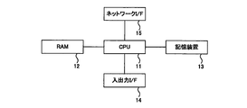
- 2 and 3 are block diagrams showing a hardware configuration and a functional configuration of the control support device according to the embodiment, respectively.
- the control support device 1 has a CPU (Central Processing Unit) 11, a RAM (Random Access Memory) 12, a storage device 13, an input / output I / F (Interface) 14, and a network I / as hardware. It is equipped with F15.
- the CPU 11 and the RAM 12 cooperate with each other to execute various functions, and the storage device 13 stores various data used for processing (control support program) executed by the various functions.
- the input / output I / F 14 inputs / outputs data to / from an input device such as a keyboard connected to the control support device 1 and an output device such as a display.
- the network I / F15 performs wired communication or wireless communication of other devices such as the operation management terminal 2, the device 3, and the operation monitoring terminal 4.
- the operation management terminal 2, the operation monitoring terminal 4, and the manufacturing management terminal 5 are assumed to have substantially the same hardware configuration as the control support device 1, and the description thereof will be omitted.
- the control support device 1 includes an acquisition unit 101, a management unit 102, an analysis unit 103, a generation unit 104, a transmission unit 105, a presentation unit 106, and an evaluation unit 107 as functions.
- the acquisition unit 101 acquires internal information, external information, and detection information, which will be described later, via the network.
- the management unit 102 manages an internal information DB (DataBase), an external information DB, a detection information DB, and a log information DB, which will be described later.
- the analysis unit 103 analyzes the operation status of the target device 3 using, for example, AI (Artificial Intelligence) based on various information managed by the management unit 102.
- AI Artificial Intelligence
- the generation unit 104 generates control information for controlling the device 3 based on the analysis result by the analysis unit 103.
- the transmission unit 105 transmits the control information generated by the generation unit 104 to the target device 3.
- the presentation unit 106 presents the analysis result by the analysis unit 103 and the information about the control information generated by the generation unit 104 to the administrator who uses the operation management terminal 2 and the monitor who uses the operation monitoring terminal 4. ..
- the evaluation unit 107 assigns an evaluation point to the analysis result by the analysis unit 103 and the control information generated by the generation unit 104 based on the input from the operation management terminal 2.
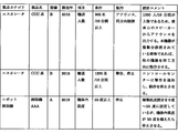
- FIG. 4 is a diagram showing design specification information.
- the internal information is information provided by the manufacturer of the device 3 as a target for analysis and control support, and examples thereof include design specification information, manufacturing process information, and post-distribution information.
- the design specification information is information determined by a design engineer, and usage conditions, detailed thresholds, and the like are associated with the model of the device 3.
- As the manufacturing process information traceability information such as information in each manufacturing process, test information, and various sensor data in the manufacturing apparatus is associated with the model of the device 3.
- Post-distribution information is information that can be grasped by the manufacturer of the device 3 after the device 3 is distributed on the market, and is information on defective products and failure information for the model of the device 3 and the production line of the device 3. , Repair information, complaint information, etc. are associated.
- model of the device 3 examples include a "model number” that classifies each device 3 having the same configuration, and a “system (product name)” that classifies each device 3 that uses the same design method.
- Each information included in the internal information is stored in the storage device of the manufacturing management terminal 5, and is acquired by the acquisition unit 101 of the control support device 1 via the network.
- Items indicating the classification of the above, the operation when the condition is satisfied, and the design comment indicating the comment by the designer about the desired operation under the corresponding condition are associated.
- the CCC system B which is an escalator, when the number of people transported is 900 people / 10 minutes or more, an announcement is output from the speaker at the entrance / exit, and the building where multiple units of this device are installed.
- CCC system B when the number of people to be transported is 1200 people / 10 minutes or more, information indicating that a warning is notified to the control center and the operation is stopped is included. In addition, information indicating that the operation of A of the vacuum cleaner AAA, which is a robot vacuum cleaner, is stopped when the temperature inside the machine becomes 55 degrees or higher is included.
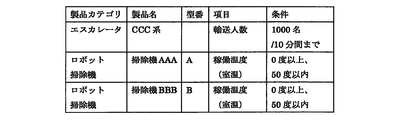
- FIG. 5 is a diagram showing product specification information.
- FIG. 6 is a diagram showing planned event information.
- FIG. 7 is a diagram showing sudden event information.
- the external information is information that can be grasped by the manager of the operation site of the device 3, and examples thereof include product specification information, planned event information, sudden event information, and SNS (Social Networking Service) information.
- Product specification information is a product specification published on the Internet.
- the planned event information is information about an event that is planned to be performed at an operation site such as an exhibition, a sports competition, a concert, a festival, or a SALE, and is input to, for example, the operation management terminal 2.
- Sudden event information is information about events that cannot be controlled by the manager of the operation site such as climate, and information published on the Internet is used.
- Product specification information, sudden event information, and SNS information shall be acquired by the acquisition unit 101 of the control support device 1 by a known method such as web scraping, and planned event information shall be input to the operation management terminal 2. After that, it is assumed that the acquisition unit 101 acquires the data via the network.
- the product specification information there are a product category indicating the type of the device 3, a product name indicating the system of the device 3, a model number of the device 3, a condition indicating a predetermined threshold value, and an item indicating the classification of the condition.
- the product specification information includes information indicating that the number of people transported is up to 1000 people / 10 minutes for the CCC system B, which is an escalator, A for the vacuum cleaner AAA, which is a robot vacuum cleaner, and D for the vacuum cleaner BBB.
- Information indicating that the operating temperature is 0 degrees or more and 50 degrees or less is included for each of the above.
- the venue, place / floor, scheduled category, start date / time, end date / time, opening date / time, closing date / time, cleaning start date / time, number of people, and area are associated.
- planned event information for example, from 10:00 to 12:00 on March 1, 2019 (Friday), a lecture will be held at the XX Hall on the 3rd floor of the XX Building in Minato-ku, Tokyo, where 3000 people will gather.
- the venue time is 9:30
- the closing time is 12:30
- the cleaning start time is 14:00.
- Sudden event information includes, for example, in Minato-ku, Tokyo, the weather in each time zone of 6: 00-12: 00, 12: 00-18: 00, 18: 00-24: 00 is sunny and rainy. , Information indicating that it is snow is included.
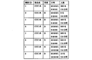
- FIG. 8 is a diagram showing device detection information related to the escalator.
- FIG. 9 is a diagram showing situation detection information regarding the escalator.
- FIG. 10 is a diagram showing device detection information related to the robot vacuum cleaner.
- FIG. 11 is a diagram showing situation detection information regarding the robot vacuum cleaner.
- the detection information includes device detection information including the measured value by the sensor provided in the device 3 and situation detection information including the measured value by the sensor installed at the operation site of the device.
- Examples of the measured values included in the device detection information include temperature, vibration, angular velocity, image, and voice.
- the measured values included in the situation detection information include the number of visitors to the facility where the device 3 as the operation site is arranged, the temperature at the facility, the amount of electric power used at the facility, and the like.
- a device ID uniquely indicating each device 3 a product name, a model number, a date and time indicating a measurement time point, and a measured value are associated with each other.
- the device detection information related to the escalator stores the number of visitors to the facility per 10 minutes as time series data
- the device detection information related to the robot vacuum cleaner is shown in FIG.
- the temperature outside the machine and the temperature inside the machine are accumulated as time-series data.
- the date and time indicating the measurement time point, the measured value, the place or the area are associated with each other.
- the situation detection information regarding the escalator accumulates the number of people entering the building as an operation site as time-series data
- the situation detection information regarding the robot vacuum cleaner is as shown in FIG.
- the temperature of the area where the operation site is located is accumulated as time series data.
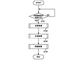
- FIG. 12 is a flowchart showing the overall operation of the control support device. In the control support device, it is assumed that the above-mentioned various information is acquired in a predetermined time cycle.
- the analysis unit 103 determines whether or not the analysis start condition is satisfied based on various information acquired by the acquisition unit 101 (S101).
- the analysis start condition is a condition for starting the analysis process described later, and is set by, for example, the analysis result previously performed.
- the analysis process may be executed unconditionally when the control support device 1 is in operation.
- the analysis start condition includes, for example, whether or not the current date and time has reached the date and time included in the planned event information, and whether or not a measured value that stands out from the past measured value is detected.
- the analysis unit 103 sets the device 3 related to the analysis start condition as the target device, analyzes the operation status of the target device, and generates analysis information. (S102), the generation unit 104 executes a generation process for generating control information for controlling the target device based on the analysis information about the target device (S103), and the evaluation unit 104 executes the analysis information and the generation process. An evaluation process for evaluating control information is executed (S104).
- the analysis unit 103 again determines whether or not the analysis start condition is satisfied (S101).
- the analysis information and the control information based on the analysis information are associated with the target device and stored in the log information DB as log information.
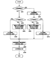
- FIG. 13 is a flowchart showing the operation of the analysis process.
- the devices have some external information and detection information, and the internal information and the log information include a mixture of devices having these and devices not having them. It is assumed that there is.
- the analysis unit 103 determines whether or not internal information about the target device exists (S201).
- the analysis unit 103 determines, for example, whether the design specification information includes information about the device 3 having the same model number as the target device.
- the analysis unit 103 determines whether or not the log information about the target device exists (S202).
- the analysis unit 103 adds the log information about another device 3 similar to the target device to the analysis target (S203).
- the similar other device 3 is a device 3 in which the target device and its external information are similar.
- the analysis unit 103 adds external information and detection information about the target device to the analysis target (S204), and based on all the information included in the analysis target, an analysis showing the analysis result of the operation status of the target device. Information is generated (S205).
- step S202 when the log information about the target device exists (S202, YES), the analysis unit 103 adds the log information about the target device to the analysis target (S206), and external information about the target device and external information about the target device and The detection information is added to the analysis target (S204).
- step S201 when the internal information about the target device exists (S201, YES), the analysis unit 103 adds the internal information about the target device to the analysis target (S207), and the log information about the target device is added. It is determined whether or not it exists (S208).
- the analysis unit 103 When there is no log information about the target device (S208, NO), the analysis unit 103 adds log information about another device 3 whose internal information is similar to that of the target device to the analysis target (S209), and the target device. External information and detection information about the above are added to the analysis target (S204).
- the analysis unit 103 adds the log information for the target device to the analysis target (S210), and analyzes the external information and the detection information for the target device. Add to (S204).
- the information necessary for the analysis of the operation status can be supplemented by adding the information about the other device 3 having similar external information to the analysis target.
- FIG. 14 is a flowchart showing the operation of the generation process.
- the generation unit 104 determines whether or not there is internal information about the target device (S301).
- the generation unit 104 controls a plurality of control information candidates or the target device based on the analysis information about the target device generated by the analysis unit 103.
- An input item for inputting necessary information is generated, and the presentation unit 106 sets a plurality of control information candidates or input items together with the analysis result shown in the analysis information via the operation management terminal 2 that manages the target device.
- the control information candidate is generated based on the internal information of the device 3 whose external information is similar to that of the target device.
- the generation unit 104 determines whether or not user input has been made for the presentation of a plurality of control information candidates or input items (S303).
- the generation unit 104 determines that the user input has been made when any of the plurality of control information candidates is selected from the plurality of control information candidates or the input items are input to the operation management terminal 2. ..
- the generation unit 104 When user input is made (S303, YES), the generation unit 104 generates control information based on the parameters and analysis information input to the selected control information candidate or input item (S304), and the transmission unit 105 generates control information.
- the control information is transmitted to the target device (S305), the management unit 102 associates the analysis information and the control information with respect to the target device, and stores the analysis information and the control information as log information in the log information DB (S306).
- the generation unit 104 determines again whether or not the user input is made (S303).
- step S301 when the internal information about the target device exists (S301, YES), the generation unit 104 generates the control information based on the internal information and the analysis information about the target device (S307), and the transmission unit 105 transmits the control information to the target device (S305).
- FIG. 15 is a flowchart showing the operation of the evaluation process.
- the evaluation unit 107 analyzes the operation information of the target device indicated by the analysis information and controls the target device based on the control information via the operation management terminal 2 that manages the target device.
- the administrator is invited to input the evaluation points (S401), and it is determined whether or not the evaluation points have been input (S402).
- the evaluation unit 107 adds the evaluation score to the log information about the target device in the log information DB (S403).
- the evaluation unit 107 determines again whether or not the evaluation points have been input (S402).
- CCC-type model numbers B which are escalators installed in a building (XX building) in Minato-ku, Tokyo, are the target devices. It is assumed that the measured value of the sensor provided in this escalator is acquired as device detection information, and the measured value of the sensor that counts the number of visitors installed at the entrance of the building is acquired as situation detection information.
- planned event information about the event held in the hall of the building shall be included in the external information DB.
- this planned event information for example, there is a lecture where 3000 people gather during the time zone from 10:00 to 12:00 on March 1, 2019 (Friday), and the opening time is 9:30 and the closing time is 9:30. Is shown to be 12:30 (Fig. 6).
- the analysis unit 103 executes an analysis process using the CCC model number B installed in the XX building as the target device, using the "opening time 9:30" as a trigger in the planned event information.
- This target device has design specification information as internal information, and as shown in FIG. 4, when the number of people transported exceeds 900 people / 10 minutes, the target device is at the entrance / exit of the escalator. Output announcements from speakers, control other escalators to move in the same direction in a building with multiple escalators, and warn the control center if more than 1200 people / 10 minutes. It is indicated to notify and stop the operation.
- the two escalators installed in this building have device IDs 1 and 2, respectively. Normally, the escalator (device ID1) operates in the upward direction and the escalator (device ID2) operates in the downward direction. Shall be.
- the analysis unit 103 analyzes the operation status of the escalator (equipment IDs 1 and 2) based on the transition of the number of people transported in the device detection information shown in FIG. 8 and the transition of the number of visitors in the situation detection information shown in FIG. To do.
- the number of escalators (device ID1) is 400 people / 10 minutes at 9:40, and according to the situation detection information, the number of visitors at the same time exceeds 1200 people / 10 minutes. You can see that. From these detection information, the analysis unit 103 predicts that people will concentrate on the escalator (device ID1) after a few minutes, and predicts the possibility that the escalator (device ID1) will be stopped from the design specification information. .. Further, the analysis unit 103 grasps that the number of people transported by the escalator (equipment ID 2) is relatively small. The analysis unit 103 generates such an analysis result as analysis information.
- the generation unit 104 controls the escalator (device ID 2) as a target device in the same direction (ascending direction) as the escalator (device ID 1) at 9:45. Generate control information. Since the number of visitors decreases sharply after the lecture start time of 10:00, the generation unit 104 generates control information for returning the escalator (device ID2) to the normal operation (downward direction). Further, at the end time of the lecture at 12:00, the generation unit 104 generates control information that operates in the same direction (downward direction) as the escalator (device ID2) with the escalator (device ID1) as the target device.
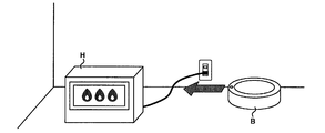
- FIG. 16 is a schematic view showing the operation of the robot vacuum cleaner to which the control support system is not applied.
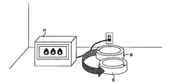
- FIG. 17 is a schematic view showing the operation of the robot vacuum cleaner to which the control support system is applied.
- the model number B of the vacuum cleaner BBB which is a robot vacuum cleaner operated in the XX building where the above-mentioned escalator is installed, is the target device.
- the measured values of the internal temperature sensor and the external temperature sensor of this robot vacuum cleaner (hereinafter referred to as robot vacuum cleaner B) are acquired as device detection information, and the measured values of the temperature sensor installed in the area where the XX building is located. Is acquired as situation detection information.
- the robot vacuum cleaner B shall be operated on the floor where the lecture shown in the planned event information is held.
- this robot vacuum cleaner B starts cleaning the floor at 14:00 after the lecture is closed.
- the outside air temperature and the inside air temperature of the robot vacuum cleaner B are acquired as device detection information every minute, and as shown in FIG. 11, the situation detection information is XX building.
- the temperature of the area where is located (Minato-ku, Tokyo) is acquired every minute.
- the analysis unit 103 starts the analysis process triggered by the fact that the outside temperature of the machine measured at 14:32 included in the device detection information is higher than other times.
- the analysis unit 103 does not change the temperature of the XX building at the time when the protruding outside temperature is measured, and in the corresponding time zone. Since the weather is rainy and the temperature outside the aircraft has risen significantly compared to the temperature inside the aircraft, an abnormality has occurred in the robot vacuum cleaner B. Specifically, FIG. As shown, it is estimated that the robot vacuum cleaner B is approaching the heat source H.
- the analysis unit 103 since the analysis unit 103 does not have the design specification information as internal information for the robot vacuum cleaner B, the analysis unit 103 refers to the product specification information (FIG. 5) as external information, and further, the robot vacuum cleaner B and the product specification information.
- the design specification information of A (hereinafter, robot vacuum cleaner A) of the vacuum cleaner AAA which is a similar robot vacuum cleaner (FIG. 4).
- the design specification information of the robot vacuum cleaner A indicates that it automatically stops when the internal temperature exceeds 55 degrees. From this information, the analysis unit 103 generates analysis information indicating that the robot vacuum cleaner B automatically stops when the robot vacuum cleaner B continues to move straight.
- the generation unit 104 generates analysis information and a plurality of control information candidates (stop, 180-degree direction change, reverse movement, etc.) or input items of parameters required for control, and the presentation unit 106 generates a plurality of control information candidates or The input items are presented to the operation management terminal 2 corresponding to the robot vacuum cleaner B.
- the generation unit 104 When the operation management terminal 2 selects a control information candidate or inputs a parameter to an input item, the generation unit 104 generates the selected control information candidate or the input control information based on the parameter, and transmits the control information. 105 transmits this control information to the robot vacuum cleaner B.
- 180-degree direction change is selected as a control information candidate, as shown in FIG. 17, the robot vacuum cleaner B changes direction in the direction opposite to the heat source H, approaches the heat source H, and eventually the robot. It is possible to avoid the automatic stop of the vacuum cleaner B and the accident that may occur when the robot vacuum cleaner B comes into contact with the heat source H.
- FIG. 18 is a schematic view showing an operation example of the device by the control support system.
- FIG. 18 shows a control support device 1 connected to an operation site where a plurality of operation management terminals 2 are installed among a plurality of operation sites (Edge).
- Each of the plurality of operation management terminals 2 is connected to a plurality of device groups, and the 1 grp device group includes a plurality of in-house devices 3a which are devices 3 manufactured by a company operating a control support system, and 2 grp, 3 grp
- the device group of is assumed to include a plurality of devices 3b manufactured by other companies, which are devices 3 manufactured by other companies.
- the analysis unit 103 analyzes the operation status of the in-house device 3a based on the information group including the internal information about the in-house device 3a, and analyzes the operation status of the in-house device 3b by the other company. Since the internal information about the manufacturing equipment 3b is not held by the management unit 102, the operation status is analyzed based on the information group (external information such as event information) that does not include the internal information.
- the generation unit 104 generates control information for controlling the in-house device 3a and the device 3b manufactured by another company based on the analysis information generated by the analysis by the analysis unit 103, and the control information is generated by the transmission unit 105. , Sent to the operation management terminal that manages the corresponding device. In addition, analysis information and control information are accumulated as log information and used for subsequent analysis.
- FIG. 19 is a schematic view showing a device to which the control support system can be applied.
- the device 3 that provides control support by the control support system is a car navigation device for a manned vehicle as shown in FIG. 31, unmanned automobile 32, building equipment 33 such as air conditioner, street light 34, drone (unmanned aerial vehicle) 35, elevator 36, factory production equipment 37, and the like.
- the car navigation device 31 is the target device, it is considered that it is realized as one function of the navigation device 31 as the operation management terminal 2, and the unmanned vehicle (taxi, bus, truck, etc.) 32 is the target device.
- the operation management terminal 2 it is conceivable to use a terminal installed in the management center of each vehicle management company as the operation management terminal 2.
- the operation management terminal 2 that manages the building equipment 33 is installed in the building management center, the operation management terminal 2 that manages the street light 34 is installed in the management center of the local government, and the operation management terminal 2 that manages the drone 35 manages the drone. It may be installed in the center.
- the elevator 36 is the target device, it is conceivable that the operation management terminal 2 is installed in the building management center and the operation monitoring terminal 4 is installed in the management center of the insurance company or the escalator maintenance company, and the escalator is the target device. The same applies when
- control support program is described as being pre-installed inside the above-mentioned control support device, but the control support program in the present invention also includes a program stored in a storage medium.
- the storage medium is a medium that can be attached to and detached from a control support device, such as a magnetic tape, a magnetic disk (hard disk drive, etc.), an optical disk (CD-ROM, DVD disk, etc.), a magneto-optical disk (MO, etc.), and a flash memory. It also refers to all media that can be read and executed by a computer as the control support device described above, such as media that can be transmitted via a network.
- Control support device 102 Management unit 103 Analysis unit 104 Generation unit
Landscapes
- Engineering & Computer Science (AREA)
- Physics & Mathematics (AREA)
- General Physics & Mathematics (AREA)
- Business, Economics & Management (AREA)
- Automation & Control Theory (AREA)
- Human Resources & Organizations (AREA)
- Strategic Management (AREA)
- Entrepreneurship & Innovation (AREA)
- Economics (AREA)
- Quality & Reliability (AREA)
- Tourism & Hospitality (AREA)
- Theoretical Computer Science (AREA)
- Educational Administration (AREA)
- General Business, Economics & Management (AREA)
- Game Theory and Decision Science (AREA)
- Development Economics (AREA)
- Marketing (AREA)
- Operations Research (AREA)
- Artificial Intelligence (AREA)
- Evolutionary Computation (AREA)
- Mathematical Physics (AREA)
- Human Computer Interaction (AREA)
- Testing And Monitoring For Control Systems (AREA)
- Management, Administration, Business Operations System, And Electronic Commerce (AREA)
Abstract
Description
本実施形態に係る制御支援システムの全体構成について説明する。
制御支援装置のハードウェア構成、機能構成について説明する。図2、図3は、それぞれ、実施形態に係る制御支援装置のハードウェア構成、機能構成を示すブロック図である。
内部情報DBに蓄積される内部情報について説明する。図4は、設計仕様情報を示す図である。
外部情報DBに蓄積される外部情報について説明する。図5は、製品仕様情報を示す図である。図6は、計画的イベント情報を示す図である。図7は、突発的イベント情報を示す図である。
検知情報DBに蓄積される検知情報について説明する。図8は、エスカレータに関する機器検知情報を示す図である。図9は、エスカレータに関する状況検知情報を示す図である。図10は、ロボット掃除機に関する機器検知情報を示す図である。図11は、ロボット掃除機に関する状況検知情報を示す図である。
制御支援装置の全体動作について説明する。図12は、制御支援装置の全体動作を示すフローチャートである。なお、制御支援装置においては、上述した各種情報が所定の時間周期で取得されているものとする。
分析処理の動作について説明する。図13は、分析処理の動作を示すフローチャートである。なお、本実施形態において、全ての機器が何らかの外部情報、検知情報を有しているものとし、内部情報、ログ情報については、これらを有している機器と有していない機器が混在しているものとする。
生成処理の動作について説明する。図14は、生成処理の動作を示すフローチャートである。
評価処理について説明する。図15は、評価処理の動作を示すフローチャートである。
制御支援システムによる対象機器がエスカレータである場合の具体例について説明する。
制御支援システムによる対象機器がロボット掃除機である場合の具体例について説明する。図16は、制御支援システムが適用されないロボット掃除機の動作を示す概略図である。図17は、制御支援システムが適用されるロボット掃除機の動作を示す概略図である。
制御支援システムの運用例について説明する。図18は、制御支援システムによる機器の運用例を示す概略図である。
制御支援システムの適用例について説明する。図19は、制御支援システムを適用可能な機器を示す概略図である。
102 管理部
103 分析部
104 生成部
Claims (11)
- 少なくとも1つ以上の所定の機器と通信可能に接続される制御支援装置であって、
前記所定の機器と該機器の内部情報とを対応付けて管理するとともに、前記所定の機器と該機器について公開される外部情報とを対応付けて管理する管理部と、
前記所定の機器における対象機器に対して、該対象機器に関連する内部情報と前記対象機器に対応する外部情報とに基づいて、運用状況を分析して分析情報を生成する分析部と
を備える制御支援装置。 - 前記対象機器に対して生成された分析情報に基づいて該対象機器を制御する制御情報を生成する生成部を更に備えることを特徴とする請求項1に記載の制御支援装置。
- 前記管理部は、前記所定の機器に対して、該機器に対して生成された前記分析情報と、該機器に対して生成された制御情報とを含むログ情報を対応付けて管理することを特徴とする請求項2に記載の制御支援装置。
- 前記分析部は、前記対象機器に対応する内部情報が存在しない場合、前記対象機器に対応する外部情報と類似する外部情報に対応する他の機器に対応するログ情報に基づいて、前記対象機器に対して運用状況を分析して分析情報を生成することを特徴とする請求項3に記載の制御支援装置。
- 前記制御支援装置は、前記所定の機器を管理する管理端末と通信可能に接続され、
前記管理端末において入力された、前記対象機器に対して生成された分析情報及び生成情報についての評価値を取得し、前記対象機器に対応するログ情報に付加する評価部を更に備えることを特徴とする請求項3または請求項4に記載の制御支援装置。 - 前記対象機器に対して生成された分析情報に基づいて、該対象機器を制御するパラメータの入力項目を前記管理端末において提示する提示部を更に備え、
前記生成部は、前記入力項目に入力されたパラメータに基づいて、前記対象機器に対する制御情報を生成することを特徴とする請求項2に記載の制御支援装置。 - 前記内部情報は、前記所定の機器の設計仕様を含むことを特徴とする請求項1~請求項6のいずれか一項に記載の制御支援装置。
- 前記外部情報は、突発的に起こる突発的イベントに関する情報、計画的に予定される計画的イベントに関する情報、前記所定の機器の製品仕様のうち、少なくとも1つを含むことを特徴とする請求項1~請求項7のいずれか一項に記載の制御支援装置。
- 少なくとも1つ以上の所定の機器と通信可能に接続されるコンピュータにおいて実行される制御支援プログラムであって、
前記コンピュータを、
前記所定の機器と該機器の製造者により提供される内部情報とを対応付けて管理するとともに、前記所定の機器と該機器について公開される外部情報とを対応付けて管理する管理部と、
前記所定の機器における対象機器に対して、該対象機器に関連する内部情報と前記対象機器に対応する外部情報とに基づいて、運用状況を分析して分析情報を生成する分析部として機能させる制御支援プログラム。 - 少なくとも1つ以上の所定の機器と通信可能に接続されるコンピュータにおいて実行される制御支援方法であって、
前記コンピュータが、
前記所定の機器と該機器の製造者により提供される内部情報とを対応付けて管理するとともに、前記所定の機器と該機器について公開される外部情報とを対応付けて管理し、
前記所定の機器における対象機器に対して、該対象機器に関連する内部情報と前記対象機器に対応する外部情報とに基づいて、運用状況を分析して分析情報を生成する制御支援方法。 - 少なくとも1つ以上の所定の機器と通信可能に接続される制御支援装置であって、
前記所定の機器と該機器について公開される外部情報とを対応付けて管理する管理部と、
前記所定の機器における対象機器に対して、該対象機器に対応する外部情報に基づいて、運用状況を分析して分析情報を生成する分析部と、
前記対象機器に対して生成された分析対象に基づいて該対象機器を制御する制御情報を生成する生成部と
を備える制御支援装置。
Priority Applications (4)
| Application Number | Priority Date | Filing Date | Title |
|---|---|---|---|
| CN202080013709.9A CN113454659B (zh) | 2019-03-28 | 2020-03-19 | 设备控制辅助装置、程序以及控制辅助方法 |
| KR1020217026706A KR102643979B1 (ko) | 2019-03-28 | 2020-03-19 | 기기 제어 지원 장치, 프로그램 및 제어 지원 방법 |
| EP20778465.3A EP3951668A4 (en) | 2019-03-28 | 2020-03-19 | Apparatus control assisting device, program, and control assisting method |
| US16/981,123 US20220121187A1 (en) | 2019-03-28 | 2020-03-19 | Device control support apparatus, program, and control support method |
Applications Claiming Priority (2)
| Application Number | Priority Date | Filing Date | Title |
|---|---|---|---|
| JP2019063172A JP6903089B2 (ja) | 2019-03-28 | 2019-03-28 | 機器制御支援装置、プログラム及び制御支援方法 |
| JP2019-063172 | 2019-03-28 |
Publications (1)
| Publication Number | Publication Date |
|---|---|
| WO2020196320A1 true WO2020196320A1 (ja) | 2020-10-01 |
Family
ID=72609401
Family Applications (1)
| Application Number | Title | Priority Date | Filing Date |
|---|---|---|---|
| PCT/JP2020/012455 Ceased WO2020196320A1 (ja) | 2019-03-28 | 2020-03-19 | 機器制御支援装置、プログラム及び制御支援方法 |
Country Status (6)
| Country | Link |
|---|---|
| US (1) | US20220121187A1 (ja) |
| EP (1) | EP3951668A4 (ja) |
| JP (3) | JP6903089B2 (ja) |
| KR (1) | KR102643979B1 (ja) |
| CN (1) | CN113454659B (ja) |
| WO (1) | WO2020196320A1 (ja) |
Families Citing this family (2)
| Publication number | Priority date | Publication date | Assignee | Title |
|---|---|---|---|---|
| CN115213910A (zh) * | 2022-09-19 | 2022-10-21 | 北京云迹科技股份有限公司 | 判断机器人是否需要暂停等待的方法及装置 |
| CN116500936B (zh) * | 2023-04-24 | 2026-03-17 | 同济大学 | 一种面向无人系统的一体化控制方法、设备、介质 |
Citations (2)
| Publication number | Priority date | Publication date | Assignee | Title |
|---|---|---|---|---|
| JP2002128400A (ja) * | 2000-10-31 | 2002-05-09 | Toshiba Corp | 昇降設備の制御装置 |
| JP2013124179A (ja) * | 2011-12-16 | 2013-06-24 | Hitachi Ltd | エレベータシステム及びエレベータの制御方法 |
Family Cites Families (16)
| Publication number | Priority date | Publication date | Assignee | Title |
|---|---|---|---|---|
| JPS5981418U (ja) | 1982-11-22 | 1984-06-01 | 安藤 誠 | 遮蔽用端部つき容器 |
| US6694234B2 (en) * | 2000-10-06 | 2004-02-17 | Gmac Insurance Company | Customer service automation systems and methods |
| JP4770869B2 (ja) * | 2001-01-30 | 2011-09-14 | 日本電気株式会社 | ロボット装置、照合環境判定方法、及び照合環境判定プログラム |
| WO2005001595A2 (en) * | 2003-06-18 | 2005-01-06 | Cnet Networks, Inc. | Content aggregation method and apparatus for on-line purchasing system |
| JP5051238B2 (ja) * | 2007-11-13 | 2012-10-17 | 富士通株式会社 | 制御代理装置 |
| US8428790B2 (en) * | 2009-12-22 | 2013-04-23 | Caterpillar Inc. | Systems and methods for machine control in designated areas |
| WO2011137935A1 (en) * | 2010-05-07 | 2011-11-10 | Ulysses Systems (Uk) Limited | System and method for identifying relevant information for an enterprise |
| JP2012226680A (ja) * | 2011-04-22 | 2012-11-15 | Internatl Business Mach Corp <Ibm> | 産業制御システムを管理する管理システム、管理方法および管理プログラム |
| JP2015176370A (ja) * | 2014-03-14 | 2015-10-05 | オムロン株式会社 | 制御システム、方法、プログラムおよび情報処理装置 |
| EP3065076A1 (en) * | 2015-03-04 | 2016-09-07 | Secure-Nok AS | System and method for responding to a cyber-attack-related incident against an industrial control system |
| CN104881019B (zh) * | 2015-03-31 | 2017-11-03 | 南昌大学 | 家电故障网络维修系统及其方法 |
| JP6539125B2 (ja) * | 2015-06-22 | 2019-07-03 | 株式会社日立製作所 | 移動ロボットシステム及び移動ロボットの制御方法 |
| JP2017048046A (ja) * | 2015-09-04 | 2017-03-09 | 村田機械株式会社 | 繊維機械管理システム |
| JP6591937B2 (ja) * | 2016-06-29 | 2019-10-16 | 株式会社日立製作所 | 運用保守知識情報の策定支援システムおよび策定支援方法 |
| US10247566B2 (en) * | 2016-12-22 | 2019-04-02 | Sap Se | Electronic navigation system |
| US10318350B2 (en) * | 2017-03-20 | 2019-06-11 | International Business Machines Corporation | Self-adjusting environmentally aware resource provisioning |
-
2019
- 2019-03-28 JP JP2019063172A patent/JP6903089B2/ja active Active
-
2020
- 2020-03-19 EP EP20778465.3A patent/EP3951668A4/en not_active Withdrawn
- 2020-03-19 CN CN202080013709.9A patent/CN113454659B/zh active Active
- 2020-03-19 KR KR1020217026706A patent/KR102643979B1/ko active Active
- 2020-03-19 WO PCT/JP2020/012455 patent/WO2020196320A1/ja not_active Ceased
- 2020-03-19 US US16/981,123 patent/US20220121187A1/en not_active Abandoned
-
2021
- 2021-06-18 JP JP2021101652A patent/JP2021152949A/ja active Pending
- 2021-06-18 JP JP2021101653A patent/JP7204824B2/ja active Active
Patent Citations (2)
| Publication number | Priority date | Publication date | Assignee | Title |
|---|---|---|---|---|
| JP2002128400A (ja) * | 2000-10-31 | 2002-05-09 | Toshiba Corp | 昇降設備の制御装置 |
| JP2013124179A (ja) * | 2011-12-16 | 2013-06-24 | Hitachi Ltd | エレベータシステム及びエレベータの制御方法 |
Non-Patent Citations (1)
| Title |
|---|
| See also references of EP3951668A4 * |
Also Published As
| Publication number | Publication date |
|---|---|
| JP2020166307A (ja) | 2020-10-08 |
| US20220121187A1 (en) | 2022-04-21 |
| JP2021152949A (ja) | 2021-09-30 |
| EP3951668A4 (en) | 2022-12-21 |
| JP6903089B2 (ja) | 2021-07-14 |
| CN113454659B (zh) | 2024-08-23 |
| CN113454659A (zh) | 2021-09-28 |
| KR20210118892A (ko) | 2021-10-01 |
| EP3951668A1 (en) | 2022-02-09 |
| KR102643979B1 (ko) | 2024-03-07 |
| JP7204824B2 (ja) | 2023-01-16 |
| JP2021152950A (ja) | 2021-09-30 |
Similar Documents
| Publication | Publication Date | Title |
|---|---|---|
| KR101768810B1 (ko) | 풍력단지 통합 제어 모니터링 시스템 | |
| EP3268819B1 (en) | Diagnostics in building automation | |
| KR101789923B1 (ko) | 풍력단지 통합제어 모니터링 방법 | |
| CN108475445A (zh) | 多源飞行器数据的自动化融合和分析的方法和系统 | |
| EP3617117B1 (en) | Model development framework for remote monitoring condition-based maintenance | |
| KR102710722B1 (ko) | 인공지능 기반 스마트 안내서비스 자율주행 무인로봇 | |
| CN120370787A (zh) | 基于智慧园区运行状态的分析监视方法及系统 | |
| JP2021152950A (ja) | 制御支援システム、プログラム及び制御支援方法 | |
| KR20160052029A (ko) | 건물 에너지 관리 지수 측정 시스템 기반 경향 분석 서비스 제공 방법 및 시스템 | |
| EP3457372A2 (en) | Method and apparatus for cloud based predictive service scheduling and evaluation | |
| KR101655247B1 (ko) | Bems 데이터를 이용한 에너지 분석 시스템 | |
| KR20220080983A (ko) | 실시간 생산현황 모니터링을 위한 IoT 엣지 컴퓨팅 시스템 | |
| Embia et al. | Edge computing‐based conditional monitoring | |
| EP3467797A2 (en) | Method and system for service verification using access control system | |
| KR20240133532A (ko) | 승객 이송 장치의 유지 관리 시스템 | |
| CN117614816A (zh) | 一种地铁站跨多设备多协议条件下的集中感知方法 | |
| KR20160126609A (ko) | 건물 에너지 분석 시스템 및 방법 | |
| KR102798634B1 (ko) | 엘리베이터의 유지 관리 시스템 | |
| D'Souza | IoT and the future of elevator maintenance business | |
| WO2017149597A1 (ja) | 機器分類装置 | |
| KR102962446B1 (ko) | 승객 이송 장치의 유지 관리 시스템 | |
| EP4501833A1 (en) | Maintenance system for passenger transport equipment | |
| EP4495039A1 (en) | Maintenance terminal and passenger transport device maintenance system using same | |
| JP4523432B2 (ja) | 統合昇降機保守情報提供システム | |
| US20140156662A1 (en) | Predicting variable identifying device, method, and program |
Legal Events
| Date | Code | Title | Description |
|---|---|---|---|
| 121 | Ep: the epo has been informed by wipo that ep was designated in this application |
Ref document number: 20778465 Country of ref document: EP Kind code of ref document: A1 |
|
| ENP | Entry into the national phase |
Ref document number: 20217026706 Country of ref document: KR Kind code of ref document: A |
|
| NENP | Non-entry into the national phase |
Ref country code: DE |
|
| ENP | Entry into the national phase |
Ref document number: 2020778465 Country of ref document: EP Effective date: 20211028 |
|
| WWW | Wipo information: withdrawn in national office |
Ref document number: 2020778465 Country of ref document: EP |