WO2020196611A1 - 硬質焼結体用の基材、硬質焼結体および切削工具 - Google Patents
硬質焼結体用の基材、硬質焼結体および切削工具 Download PDFInfo
- Publication number
- WO2020196611A1 WO2020196611A1 PCT/JP2020/013297 JP2020013297W WO2020196611A1 WO 2020196611 A1 WO2020196611 A1 WO 2020196611A1 JP 2020013297 W JP2020013297 W JP 2020013297W WO 2020196611 A1 WO2020196611 A1 WO 2020196611A1
- Authority
- WO
- WIPO (PCT)
- Prior art keywords
- base material
- sintered body
- hard sintered
- inclined portion
- axial direction
- Prior art date
- Legal status (The legal status is an assumption and is not a legal conclusion. Google has not performed a legal analysis and makes no representation as to the accuracy of the status listed.)
- Ceased
Links
Images






Classifications
-
- B—PERFORMING OPERATIONS; TRANSPORTING
- B23—MACHINE TOOLS; METAL-WORKING NOT OTHERWISE PROVIDED FOR
- B23C—MILLING
- B23C5/00—Milling-cutters
- B23C5/02—Milling-cutters characterised by the shape of the cutter
- B23C5/10—Shank-type cutters, i.e. with an integral shaft
-
- B—PERFORMING OPERATIONS; TRANSPORTING
- B23—MACHINE TOOLS; METAL-WORKING NOT OTHERWISE PROVIDED FOR
- B23P—METAL-WORKING NOT OTHERWISE PROVIDED FOR; COMBINED OPERATIONS; UNIVERSAL MACHINE TOOLS
- B23P15/00—Making specific metal objects by operations not covered by a single other subclass or a group in this subclass
- B23P15/28—Making specific metal objects by operations not covered by a single other subclass or a group in this subclass cutting tools
- B23P15/34—Making specific metal objects by operations not covered by a single other subclass or a group in this subclass cutting tools milling cutters
-
- C—CHEMISTRY; METALLURGY
- C22—METALLURGY; FERROUS OR NON-FERROUS ALLOYS; TREATMENT OF ALLOYS OR NON-FERROUS METALS
- C22C—ALLOYS
- C22C26/00—Alloys containing diamond or cubic or wurtzitic boron nitride, fullerenes or carbon nanotubes
-
- B—PERFORMING OPERATIONS; TRANSPORTING
- B22—CASTING; POWDER METALLURGY
- B22F—WORKING METALLIC POWDER; MANUFACTURE OF ARTICLES FROM METALLIC POWDER; MAKING METALLIC POWDER; APPARATUS OR DEVICES SPECIALLY ADAPTED FOR METALLIC POWDER
- B22F5/00—Manufacture of workpieces or articles from metallic powder characterised by the special shape of the product
- B22F2005/001—Cutting tools, earth boring or grinding tool other than table ware
-
- B—PERFORMING OPERATIONS; TRANSPORTING
- B23—MACHINE TOOLS; METAL-WORKING NOT OTHERWISE PROVIDED FOR
- B23C—MILLING
- B23C2210/00—Details of milling cutters
- B23C2210/03—Cutting heads comprised of different material than the shank irrespective of whether the head is detachable from the shank
-
- B—PERFORMING OPERATIONS; TRANSPORTING
- B23—MACHINE TOOLS; METAL-WORKING NOT OTHERWISE PROVIDED FOR
- B23C—MILLING
- B23C2226/00—Materials of tools or workpieces not comprising a metal
- B23C2226/12—Boron nitride
- B23C2226/125—Boron nitride cubic [CBN]
-
- B—PERFORMING OPERATIONS; TRANSPORTING
- B23—MACHINE TOOLS; METAL-WORKING NOT OTHERWISE PROVIDED FOR
- B23C—MILLING
- B23C2226/00—Materials of tools or workpieces not comprising a metal
- B23C2226/31—Diamond
- B23C2226/315—Diamond polycrystalline [PCD]
-
- B—PERFORMING OPERATIONS; TRANSPORTING
- B23—MACHINE TOOLS; METAL-WORKING NOT OTHERWISE PROVIDED FOR
- B23C—MILLING
- B23C2228/00—Properties of materials of tools or workpieces, materials of tools or workpieces applied in a specific manner
- B23C2228/49—Sintered
-
- B—PERFORMING OPERATIONS; TRANSPORTING
- B23—MACHINE TOOLS; METAL-WORKING NOT OTHERWISE PROVIDED FOR
- B23C—MILLING
- B23C2240/00—Details of connections of tools or workpieces
- B23C2240/08—Brazed connections
Definitions
- the present invention relates to a base material for a hard sintered body, a hard sintered body and a cutting tool.
- the present application claims priority based on Japanese Patent Application No. 2019-058625 filed in Japan on March 26, 2019, the contents of which are incorporated herein by reference.
- a cutting tool such as end mills, reamers and drills are known.
- a cutting tool is manufactured by grinding a columnar tool material to form a chip discharge groove, a cutting edge, or the like.
- the tool material is manufactured by brazing a hard sintered body that constitutes a blade portion and a cemented carbide shank.
- the hard sintered body includes a multi-stage cylindrical base material and a cylindrical tubular portion that covers the small diameter portion of the base material.
- the base material is made of cemented carbide
- the tubular portion is made of polycrystalline diamond (PCD) or polycrystalline cubic boron nitride (PcBN).
- PCD polycrystalline diamond
- PcBN polycrystalline cubic boron nitride
- the base material and the tubular portion are integrally sintered to form a hard sintered body.
- Patent Documents 1 and 2 are known as conventional hard sintered bodies.
- the coefficient of linear expansion (coefficient of thermal expansion) of the base material and the coefficient of linear expansion of the cylinder are significantly different.
- the coefficient of linear expansion of the cylinder portion is about half of the coefficient of linear expansion of the base material. Therefore, when the hard sintered body and the shank are brazed, cracks may occur in the vicinity of the interface between the tubular portion and the base material due to thermal stress.
- one of the objects of the present invention is to provide a base material for a hard sintered body, a hard sintered body, and a cutting tool capable of suppressing the occurrence of cracks in the hard sintered body.
- One aspect of the present invention is a base material for a multi-stage columnar hard sintered body having a central axis and extending in the axial direction of the central axis, and has a small diameter portion and an outer diameter larger than that of the small diameter portion.
- a base material end face located between the large-diameter portion, one end of the outer peripheral surface of the large-diameter portion in the axial direction and the other end of the small-diameter portion in the axial direction, and facing one side in the axial direction.
- a first inclined portion arranged in at least a part in the circumferential direction is provided, and the first inclined portion is a shaft.
- one aspect of the hard sintered body of the present invention is the above-mentioned base material for the hard sintered body and the tubular shape covering the small diameter portion, which is linearly expanded compared to the base material for the hard sintered body.
- a tubular portion having a small coefficient and a high hardness and sintered integrally with the base material for the hard sintered body is provided, and the inner peripheral surface of the tubular portion is joined to the outer peripheral surface of the small diameter portion.
- the end surface of the cylinder portion facing the other side in the axial direction of the cylinder portion is joined to the end surface of the base material, and the cylinder portion is among the annular corner portions connecting the outer peripheral surface of the cylinder portion and the end surface of the cylinder portion.
- the second inclined portion has a second inclined portion arranged at least a part in the circumferential direction, and the second inclined portion is located radially inward toward one side in the axial direction and is joined to the first inclined portion.
- one aspect of the cutting tool of the present invention is to connect a blade portion provided with a chip discharge groove and a cutting blade extending in the axial direction to the outer peripheral portion of the above-mentioned hard sintered body in the axial direction.
- the cutting edge is arranged in the tubular portion.
- the first inclined portion is located at the corner portion where the outer peripheral surface of the large diameter portion of the base material and the end face of the base material are connected. are doing.
- the tubular portion that is integrally sintered with the base material is provided with a second inclined portion that is joined to the first inclined portion.
- the volume of the base material is reduced by providing the first inclined portion and the second inclined portion. The volume of the cylinder increases. That is, the volume of the base material is kept small, and the volume of the tubular portion is secured large.
- the thermal stress that the tubular portion receives from the base material can be reduced.
- the effect of increasing the joint strength between the base material and the cylinder portion can be obtained by increasing the contact area between the base material and the cylinder portion.
- the thermal stress generated when brazing the hard sintered body and the shank acts in the direction perpendicular to the central axis of the base material. That is, at the time of brazing, a shearing force is likely to be generated along the surface direction of the base material end face and the cylinder end face.
- a first inclined portion that is recessed in the axial direction from the end face of the base material is provided, and a second inclined portion that protrudes in the axial direction from the end face of the tubular portion is provided. Therefore, at the time of brazing, the thermal stress in the shear direction perpendicular to the central axis is reduced by the amount that the force is released in the direction perpendicular to the first inclined portion and the second inclined portion.
- the present invention it is possible to obtain a hard sintered body that can withstand thermal stress during brazing, and it is possible to suppress the occurrence of cracks in the hard sintered body. Then, a cutting tool using this hard sintered body for the blade portion can be efficiently and stably manufactured.
- the base material for the hard sintered body has an angle between the virtual plane perpendicular to the central axis and the first inclined portion of 10 ° or more and 75 ° or less in a vertical cross-sectional view along the central axis. It is preferable to have.
- the first inclined portion is too close to the end face of the large diameter portion facing the other side in the axial direction. Can be suppressed. That is, it is possible to prevent the first inclined portion from getting too close to the brazed portion (joint portion) between the hard sintered body and the shank.
- the second inclined portion that is joined to the first inclined portion is arranged away from the heat source for induction heating during brazing, and the second inclined portion Changes in material properties are suppressed. Specifically, for example, when the tubular portion is made of PCD, it is possible to suppress a problem that the diamond particles constituting the second inclined portion are graphitized by the heat source and the strength is lowered.
- the maximum depth at which the first inclined portion is recessed inward in the radial direction from the outer peripheral surface of the large diameter portion is 5% or more of the diameter of the large diameter portion. It is preferably equal to or less than the value of the difference between the radius of the large diameter portion and the radius of the small diameter portion.
- the maximum depth at which the first inclined portion is recessed inward in the radial direction from the outer peripheral surface of the large-diameter portion is 5% or more of the diameter of the large-diameter portion, a large radial length of the first inclined portion is secured. Therefore, the volume of the base material is stably kept small. As a result, the thermal stress that the tubular portion that is sintered integrally with the base material receives from the base material during brazing can be stably reduced. Further, at the time of brazing, stress can be easily released in the direction perpendicular to the first inclined portion, and cracks can be more stably suppressed in the hard sintered body.
- the first inclined portion is the small diameter portion.
- This base material can be stably produced by suppressing interference with the material.
- the first inclined portion has a concave shape in which the depth in the radial direction becomes deeper toward one side in the axial direction, and the first inclined portions are spaced apart from each other in the circumferential direction. It is preferable to open a plurality of them at the corners.
- the first inclined portion has a concave shape such as a groove shape (slit shape), and equal or unequal intervals are provided in the circumferential direction at the corner portion where the outer peripheral surface of the large diameter portion and the end surface of the base material are connected. Multiple are provided. Therefore, the degree of freedom in arranging the first inclined portion is increased, and it is possible to easily cope with various hard sintered bodies used in various cutting tools. In the above configuration, when the hard sintered body is given the shape of a chip discharge groove or a cutting edge to form a cutting tool blade, some of the plurality of first inclined portions are removed by grinding. May be good.
- the base material for the hard sintered body preferably has a circumferential length of the first inclined portion of 10% or more and 80% or less of the diameter of the large diameter portion.
- the first inclined portion When the circumferential length of the first inclined portion is 10% or more of the diameter of the large diameter portion, the first inclined portion is recessed at the corner portion where the outer peripheral surface of the large diameter portion of the base material and the end surface of the base material are connected. A large capacity of the part is secured, and the volume of the base material is stably kept small. As a result, the thermal stress that the tubular portion that is sintered integrally with the base material receives from the base material during brazing can be stably reduced. Further, at the time of brazing, stress can be easily released by the first inclined portion having a large capacity, and cracks can be more stably suppressed in the hard sintered body.
- the number of concave first inclined portions recessed at the corners can be arranged in the circumferential direction, and a plurality of concave portions can be arranged in the circumferential direction.
- a large total area of the wall surface portion facing the circumferential direction of the first inclined portion is secured.
- a large total area where the plurality of first inclined portions and the plurality of second inclined portions are in contact with each other in the circumferential direction is secured, and it becomes easier to withstand the thermal stress generated during brazing.
- the first inclined portion is connected to an inclined surface located radially inward toward one side in the axial direction and both ends in the circumferential direction of the inclined surface in the circumferential direction. It is preferable to have a pair of side wall surfaces arranged so as to face each other at intervals.
- the first inclined portion is formed by two wall surfaces in a V-shaped cross section or the like
- a large capacity of the first inclined portion can be secured, and the volume of the base material can be suppressed by that amount.
- the thermal stress that the tubular portion that is sintered integrally with the base material receives from the base material during brazing can be stably reduced.
- stress can be easily released by the first inclined portion having a large capacity, and cracks can be more stably suppressed in the hard sintered body.
- the pair of side wall surfaces are separated from each other in the circumferential direction toward the outer side in the radial direction.
- the capacity of the first inclined portion can be secured larger, and the volume of the base material can be suppressed to be smaller.
- the first inclined portion is arranged over the entire circumference of the corner portion.
- the first inclined portion is annular, and is provided at the corner portion where the outer peripheral surface of the large diameter portion and the end surface of the base material are connected over the entire circumferential direction. Therefore, the capacity of the first inclined portion can be stably secured to be large, and the volume of the base material can be suppressed accordingly. As a result, the thermal stress that the tubular portion that is sintered integrally with the base material receives from the base material during brazing can be stably reduced. Further, at the time of brazing, stress can be easily released by the first inclined portion having a large capacity, and cracks can be more stably suppressed in the hard sintered body.
- the first inclined portion has a concave curved surface portion having a concave curved surface shape.
- first inclined portion a large surface area of the wall surface constituting the first inclined portion can be secured, and the joint strength between the first inclined portion and the second inclined portion of the tubular portion that is sintered integrally with the base material is enhanced. Further, it is possible to make it difficult to generate a portion where thermal stress is concentrated near the wall surface of the first inclined portion, and it is possible to further suppress the occurrence of cracks in the hard sintered body. In addition, it is easy to secure a larger capacity of the first inclined portion.
- the first inclined portion has a convex curved surface portion having a convex curved surface shape.
- a large surface area of the wall surface constituting the first inclined portion can be secured, and the joint strength between the first inclined portion and the second inclined portion of the tubular portion that is sintered integrally with the base material is enhanced. Further, it is possible to make it difficult to generate a portion where thermal stress is concentrated near the wall surface of the first inclined portion, and it is possible to further suppress the occurrence of cracks in the hard sintered body.
- the base material for the hard sintered body has a Young's modulus of 300 GPa or more, and the tubular portion has a Young's modulus of 600 GPa or more.
- the Young's modulus of the base material for a hard sintered body is 300 GPa or more, stable rigidity can be ensured when this base material is used for a cutting tool such as an end mill. Further, when the Young's modulus of the tubular portion is 600 GPa or more, stable wear resistance can be ensured when the tubular portion is used for a cutting tool such as an end mill.
- the base material for the hard sintered body is made of cemented carbide, cermet, or ceramics, and the tubular portion is made of polycrystalline diamond or polycrystalline cubic boron nitride. It is preferably made of either.
- the base material, the hard sintered body, and the cutting tool for the hard sintered body according to one aspect of the present invention, it is possible to suppress the occurrence of cracks in the hard sintered body.
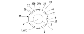
- FIG. 1 is a top view showing the hard sintered body of the first embodiment.
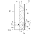
- FIG. 2 is a side view and a side sectional view (longitudinal sectional view) showing the hard sintered body of the first embodiment.
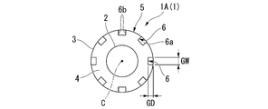
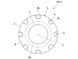
- FIG. 3 is a top view showing a base material for the hard sintered body of the first embodiment.
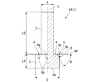
- FIG. 4 is a side view and a side sectional view (longitudinal sectional view) showing a base material for the hard sintered body of the first embodiment.
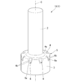
- FIG. 5 is a perspective view showing a base material for the hard sintered body of the first embodiment.
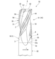
- FIG. 6 is a side view showing the cutting tool of the first embodiment.
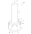
- FIG. 7 is a perspective view showing a first modification of the base material for the hard sintered body of the first embodiment.
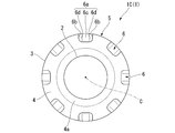
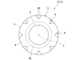
- FIG. 8 is a top view showing a first modification of the base material for the hard sintered body of the first embodiment.
- FIG. 9 is a perspective view showing a second modification of the base material for the hard sintered body of the first embodiment.
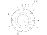
- FIG. 10 is a top view showing a second modification of the base material for the hard sintered body of the first embodiment.
- FIG. 11 is a perspective view showing a third modification of the base material for the hard sintered body of the first embodiment.
- FIG. 12 is a top view showing a third modification of the base material for the hard sintered body of the first embodiment.
- FIG. 13 is a perspective view showing a fourth modification of the base material for the hard sintered body of the first embodiment.
- FIG. 14 is a top view showing a fourth modification of the base material for the hard sintered body of the first embodiment.
- FIG. 15 is a perspective view showing a fifth modification of the base material for the hard sintered body of the first embodiment.
- FIG. 16 is a top view showing a fifth modification of the base material for the hard sintered body of the first embodiment.
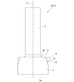
- FIG. 17 is a side view showing a base material for the hard sintered body of the second embodiment.
- FIG. 18 is a side view showing a modified example of the base material for the hard sintered body of the second embodiment.
- the base material 1A (1) for the hard sintered body, the hard sintered body 10 and the cutting tool 50 according to the first embodiment of the present invention will be described with reference to FIGS. 1 to 6.
- 1 and 2 show the hard sintered body 10 of the present embodiment.
- 3 to 5 show the base material 1A for the hard sintered body of the present embodiment.
- FIG. 6 shows the cutting tool 50 of this embodiment.
- the base material 1A for the hard sintered body may be simply referred to as the base material 1A.
- the hard sintered body 10 may be paraphrased as an ultra-hard sintered body 10 or an ultra-hardness sintered body 10.
- the hard sintered body 10 includes a base material 1A for the hard sintered body and a tubular portion 20 integrally sintered with the base material 1A for the hard sintered body. Be prepared.
- the substrate 1A has a Young's modulus of 300 GPa or more.
- the base material 1A is made of cemented carbide, cermet, or ceramics.
- the tubular portion 20 has a Young's modulus of 600 GPa or more.
- the tubular portion 20 is made of either polycrystalline diamond (PCD) or polycrystalline cubic boron nitride (PcBN).
- PCD polycrystalline diamond
- PcBN polycrystalline cubic boron nitride
- the Young's modulus of the base material 1A for the hard sintered body is preferably 550 GPa or more and 650 GPa or less, and the Young's modulus of the tubular portion 20 is preferably 800 GPa or more and 950 GPa or less.
- the hard sintered body 10 is formed by filling a cylindrical capsule (not shown) with a base material 1A raw material as a powder compact and a powdery tubular portion 20 raw material, and sintering the hard sintered body 10 under ultra-high temperature and ultra-high pressure conditions.
- the base material 1A has a central axis C and is a multi-stage columnar shape extending in the axial direction of the central axis C. Specifically, the base material 1A is a multi-stage columnar centered on the central axis C.
- the base material 1A includes a small diameter portion 2, a large diameter portion 3, a base material end face 4, a corner portion 5, and a first inclined portion 6.
- the direction in which the central axis C of the base material 1A extends is referred to as an axial direction.
- the small diameter portion 2 and the large diameter portion 3 are arranged at different positions from each other.
- the direction from the large diameter portion 3 to the small diameter portion 2 is referred to as one side in the axial direction, and the direction from the small diameter portion 2 to the large diameter portion 3 is referred to as the other side in the axial direction.
- the direction orthogonal to the central axis C is called the radial direction.
- the direction closer to the central axis C is called the radial inner side, and the direction away from the central axis C is called the radial outer side.
- the direction that orbits around the central axis C is called the circumferential direction.
- the predetermined rotation direction is called the circumferential direction one side, and the rotation direction opposite to this is called the circumferential direction other side.
- the central axis C of the base material 1A, the central axis C of the hard sintered body 10, and the central axis C of the cutting tool 50 are common axes and are arranged coaxially with each other.
- One side in the axial direction corresponds to the tip side (upper side in FIG. 6) of the cutting tool 50 shown in FIG.
- the other side in the axial direction corresponds to the rear end side (lower side in FIG. 6) of the cutting tool 50.
- the direction in which the cutting tool 50 is rotated by the spindle of the machine tool during cutting is called the tool rotation direction T, and the direction opposite to this is the direction opposite to the tool rotation direction T (anti-tool). (Rotation direction) may be called.
- one side in the circumferential direction corresponds to the tool rotation direction T
- the other side in the circumferential direction corresponds to the direction opposite to the tool rotation direction T.
- the small diameter portion 2 is a columnar shape extending in the axial direction.
- the large diameter portion 3 is a columnar shape extending in the axial direction.
- the large diameter portion 3 has a larger outer diameter than the small diameter portion 2.
- the outer diameter (diameter) D of the large diameter portion 3 is approximately twice the outer diameter d of the small diameter portion 2.
- the large diameter portion 3 has a smaller axial length than the small diameter portion 2.
- the axial length L1 of the large diameter portion 3 is approximately 1/3 times the axial length L2 of the small diameter portion 2.
- the end surface 3a of the large diameter portion 3 facing the other side in the axial direction has a planar shape extending in a direction perpendicular to the central axis C.
- the end face 3a has a circular shape.
- the base material end surface 4 is located between one end of the outer peripheral surface of the large diameter portion 3 in the axial direction and the other end of the small diameter portion 2 in the axial direction, and faces one side in the axial direction.
- the base material end surface 4 is arranged between the end portion of the outer peripheral surface of the large diameter portion 3 on one side in the axial direction and the end portion of the outer peripheral surface of the small diameter portion 2 on the other side in the axial direction.
- the base material end face 4 is a circular ring centered on the central axis C.
- the base material end face 4 has a planar shape extending in a direction perpendicular to the central axis C. As shown in FIG.
- the base material end face 4 may have a corner concave curved surface portion 4a on the inner peripheral portion of the base material end face 4 connected to the small diameter portion 2.
- the corner concave curved surface portion 4a is a circular annular concave curved surface centered on the central axis C.
- the corner concave curved surface portion 4a is located on one side in the axial direction as it goes inward in the radial direction.
- the corner concave curved surface portion 4a In a vertical cross-sectional view along the central axis C, the corner concave curved surface portion 4a has a concave curved shape, and is recessed inward in the radial direction and toward the other side in the axial direction.
- the corner portion 5 is a convex portion where the outer peripheral surface of the large diameter portion 3 and the base material end surface 4 are connected.
- the corner portion 5 is an annular shape centered on the central axis C and extends in the circumferential direction.
- the corner portion 5 has a circular ring shape.
- the corner portion 5 may be rephrased as the base material corner portion 5.
- the first inclined portion 6 is arranged at least a part of the corner portion 5 in the circumferential direction.
- the first inclined portion 6 is located inward in the radial direction toward one side in the axial direction. That is, the first inclined portion 6 extends inward in the radial direction toward one side in the axial direction.
- the inner portion of the first inclined portion 6 located inward in the radial direction that is, the surface portion or valley portion which is the bottom portion of the first inclined portion 6 is located inward in the radial direction toward one side in the axial direction.
- the angle ⁇ between the virtual plane VP perpendicular to the central axis C and the first inclined portion 6 is 10 ° or more and 75 ° or less in the vertical cross-sectional view along the central axis C.
- the angle ⁇ is the acute angle among the acute and obtuse angles formed between the virtual plane VP and the inner portion of the first inclined portion 6 located on the inner side in the radial direction. is there.
- the angle ⁇ between the virtual plane VP perpendicular to the central axis C and the first inclined portion 6 is preferably 45 ° or more and 60 ° or less.
- the first inclined portion 6 has a concave shape that is recessed at the corner portion 5, and has a groove shape (slit shape) in the illustrated example.
- the first inclined portion 6 extends in the axial direction and the radial direction.
- the first inclined portion 6 is recessed from the end surface 4 of the base material to the other side in the axial direction, and is recessed inward in the radial direction from the outer peripheral surface of the large diameter portion 3.
- a plurality of first inclined portions 6 are provided at the corner portions 5 at intervals in the circumferential direction.
- a plurality (8) first inclined portions 6 are arranged at equal intervals (equal pitch) in the circumferential direction.
- the present invention is not limited to this, and the plurality of first inclined portions 6 may be arranged at unequal intervals (at unequal pitches) in the circumferential direction.
- the depth of the first inclined portion 6 in the axial direction becomes deeper toward the outer side in the radial direction.
- the depth of the first inclined portion 6 becomes deeper in the radial direction toward one side in the axial direction.
- the maximum depth (groove depth) GD at which the first inclined portion 6 is recessed inward in the radial direction from the outer peripheral surface of the large diameter portion 3 is 5% or more of the diameter D of the large diameter portion 3. Yes, it is less than or equal to the value (D / 2-d / 2) of the difference between the radius D / 2 of the large diameter portion 3 and the radius d / 2 of the small diameter portion 2.
- the maximum depth GD may be rephrased as the radial length at one end of the first inclined portion 6 in the axial direction.
- the maximum depth GD at which the first inclined portion 6 is recessed inward in the radial direction from the outer peripheral surface of the large diameter portion 3 is 10% or more of the diameter D of the large diameter portion 3, and 20% of the diameter D of the large diameter portion 3. The following is preferable.
- the circumferential length (groove width) GW of the first inclined portion 6 is 10% or more and 80% or less of the diameter D of the large diameter portion 3.
- the circumferential length GW of the first inclined portion 6 is the opening dimension at the radial outer end of the first inclined portion 6 when the base material 1A is viewed from the axial direction as shown in FIG. Corresponds to.
- the circumferential length GW of the first inclined portion 6 is preferably 10% or more and 20% or less of the diameter D of the large diameter portion 3.
- the first inclined portion 6 has a first inclined surface (inclined surface) 6a and a pair of first side wall surfaces (side wall surfaces) 6b.
- the first inclined surface 6a is located inward in the radial direction toward one side in the axial direction.
- the first inclined surface 6a is flat.
- the first inclined surface 6a faces the outer side in the radial direction and one side in the axial direction.
- the first inclined surface 6a has a quadrangular shape.
- the pair of first side wall surfaces 6b are connected to both ends of the first inclined surface 6a in the circumferential direction, and are arranged so as to face each other at intervals in the circumferential direction.
- the first side wall surface 6b has a planar shape extending in the directions perpendicular to the circumferential direction (axial direction and radial direction).
- the first side wall surface 6b has a triangular shape.
- the tubular portion 20 has a tubular shape that covers the small diameter portion 2.
- the tubular portion 20 has a cylindrical shape centered on the central axis C and extends in the axial direction.
- the tubular portion 20 has a ridged tubular shape.
- the tubular portion 20 has a peripheral wall portion 21, a top wall portion 22, a tubular portion end surface 23, a corner portion 24, and a second inclined portion 25.
- the peripheral wall portion 21 has a cylindrical shape extending in the axial direction.
- the peripheral wall portion 21 surrounds the small diameter portion 2 from the outside in the radial direction.
- the inner peripheral surface of the peripheral wall portion 21 is fixed to the outer peripheral surface of the small diameter portion 2.
- the inner peripheral surface of the peripheral wall portion 21 (that is, the inner peripheral surface of the tubular portion 20) is joined to the outer peripheral surface of the small diameter portion 2.
- the top wall portion 22 is connected to one end of the peripheral wall portion 21 in the axial direction.
- the top wall portion 22 has a disk shape centered on the central axis C.
- the pair of plate surfaces of the top wall portion 22 face in the axial direction.
- the plate surface of the top wall portion 22 facing the other side in the axial direction is fixed to the end surface of the small diameter portion 2 facing the other side in the axial direction.
- the plate surface of the top wall portion 22 facing the other side in the axial direction is joined to the end surface of the small diameter portion 2 facing the other side in the axial direction.
- the tubular portion end surface 23 is located at the end of the peripheral wall portion 21 on the other side in the axial direction and faces the other side in the axial direction.
- the tubular portion end surface 23 is a circular ring centered on the central axis C.
- the end surface 23 of the tubular portion has a planar shape extending in a direction perpendicular to the central axis C.
- the tubular portion end face 23 is fixed to the base material end face 4.
- the tubular portion end surface 23 is joined to the base material end surface 4.
- the corner portion 24 is a convex portion connecting the outer peripheral surface of the peripheral wall portion 21 (that is, the outer peripheral surface of the tubular portion 20) and the end surface 23 of the tubular portion.
- the corner portion 24 has an annular shape centered on the central axis C and extends in the circumferential direction.
- the corner portion 24 has a circular ring shape.
- the corner portion 24 may be rephrased as a cylinder portion corner portion 24.
- the second inclined portion 25 is arranged at least a part of the corner portion 24 in the circumferential direction.
- the second inclined portion 25 is located inward in the radial direction toward one side in the axial direction.
- the inner portion of the second inclined portion 25 located inward in the radial direction that is, the surface portion or ridge portion facing inward in the radial direction in the second inclined portion 25 becomes inward in the radial direction toward one side in the axial direction. It is located and extends at an angle with respect to the central axis C.
- the second inclined portion 25 is fixed to the first inclined portion 6.
- the second inclined portion 25 is joined to the first inclined portion 6.
- the second inclined portion 25 has a convex shape protruding from the corner portion 24, specifically, a protruding shape or a rib shape.
- the second inclined portion 25 extends in the axial direction and the radial direction.
- the second inclined portion 25 projects from the end surface 23 of the tubular portion to the other side in the axial direction.
- the outer side portion (outer peripheral surface) located on the radial outer side of the second inclined portion 25 overlaps with the outer peripheral surface of the peripheral wall portion 21 when viewed from the axial direction.
- the outer portion located on the radial outer side of the second inclined portion 25 is arranged flush with the outer peripheral surface of the peripheral wall portion 21.
- a plurality of second inclined portions 25 are provided at the corner portions 24 at intervals in the circumferential direction.
- a plurality of (eight) second inclined portions 25 are arranged at equal intervals (equal pitch) in the circumferential direction.
- the present invention is not limited to this, and the plurality of second inclined portions 25 may be arranged at unequal intervals (at unequal pitches) in the circumferential direction.
- the angle between the virtual plane VP perpendicular to the central axis C and the second inclined portion 25 in the vertical cross-sectional view along the central axis C is the same value as the above-mentioned angle ⁇ (10 ° or more and 75 ° or less). .. Specifically, in this vertical cross-sectional view, the angle is an acute angle among the acute angles and obtuse angles formed between the virtual plane VP and the inner portion of the second inclined portion 25 located on the inner side in the radial direction. is there.
- the length (height) of the second inclined portion 25 in the axial direction increases toward the outside in the radial direction.
- the length of the second inclined portion 25 increases in the radial direction toward one side in the axial direction.
- the maximum radial length of the second inclined portion 25 is the same value as the maximum depth GD of the first inclined portion 6 described above.
- the maximum radial length of the second inclined portion 25 is equal to the radial length from the outer peripheral surface of the peripheral wall portion 21 to the radial inner end portion of the second inclined portion 25.
- the maximum radial length of the second inclined portion 25 may be rephrased as the radial length at one end of the second inclined portion 25 in the axial direction.
- the circumferential length (projection width, rib width) of the second inclined portion 25 is the same value as the circumferential length GW of the first inclined portion 6 described above.
- the second inclined portion 25 has a second inclined surface 25a and a pair of second side wall surfaces 25b.
- the second inclined surface 25a is located inward in the radial direction toward one side in the axial direction.
- the second inclined surface 25a is flat.
- the second inclined surface 25a faces the inside in the radial direction and the other side in the axial direction.
- the second inclined surface 25a has a quadrangular shape.
- the second inclined surface 25a has the same shape as the first inclined surface 6a.
- the second inclined surface 25a is joined to the first inclined surface 6a.
- the pair of second side wall surfaces 25b are connected to both ends of the second inclined surface 25a in the circumferential direction, and are arranged back to back at intervals in the circumferential direction.
- the second side wall surface 25b has a planar shape extending in the directions perpendicular to the circumferential direction (axial direction and radial direction).
- the second side wall surface 25b has a triangular shape.
- the second side wall surface 25b has the same shape as the first side wall surface 6b.
- the second side wall surface 25b is joined to the first side wall surface 6b.
- the cutting tool 50 is a rotary cutting tool (rolling tool), specifically, an end mill, a reamer, a drill, or the like. As shown in FIG. 6, the cutting tool 50 of this embodiment is an end mill.
- the cutting tool 50 is axially connected to a blade portion 51 provided with a chip discharge groove 55 extending in the axial direction and a cutting edge (outer peripheral blade) 56 on the outer peripheral portion of the above-mentioned hard sintered body 10.
- the shank 52 is provided. That is, the blade portion 51 is manufactured by grinding a chip discharge groove 55 and a cutting blade 56 on the outer peripheral portion of the hard sintered body 10 with a grinding wheel or the like. That is, the hard sintered body 10 is a material for manufacturing the blade portion 51, and is an intermediate body of the blade portion 51 manufactured in the manufacturing process of the cutting tool 50.
- the outer peripheral surface of the blade portion 51 is arranged on the peripheral wall portion 21 of the tubular portion 20.
- the hard sintered body 10 When the hard sintered body 10 is provided with the shapes of the chip discharge groove 55 and the cutting edge 56 to form the blade portion 51 of the cutting tool 50, some of the plurality of first inclined portions 6 and a plurality of first inclined portions 6 are formed. 2 Some of the inclined portions 25 may be selectively removed by grinding.
- the shank 52 is made of cemented carbide.
- the shank 52 is a columnar shape extending in the axial direction.
- the blade portion 51 and the shank 52 are joined to each other by, for example, brazing by induction heating under vacuum using Ag brazing. That is, the end face (end face of the large diameter portion 3) 3a facing the other side in the axial direction of the blade portion 51 and the end face 52a facing one side in the axial direction of the shank 52 are joined to each other by brazing.
- the cutting tool 50 is detachably attached to a machine tool spindle or the like whose shank 52 is not shown, and is rotated around the central axis C by the machine tool spindle or the like to cut (roll) the work material. ..
- the work material is, for example, made of metal.
- the chip discharge groove 55 is recessed inward in the radial direction from the outer peripheral surface of the cutting tool 50 and extends in the axial direction.
- the chip discharge groove 55 is directed in the direction opposite to the tool rotation direction T from the end (tip) on one side of the cutting tool 50 in the axial direction to the other side (rear end) in the axial direction. It extends in a spiral.
- the present invention is not limited to this, and the chip discharge groove 55 may extend in the axial direction in parallel with the central axis C.
- At least one chip discharge groove 55 is provided in the cutting tool 50.
- a plurality of chip discharge grooves 55 are provided.
- the plurality of chip discharge grooves 55 are arranged so as to be spaced apart from each other in the circumferential direction.
- the plurality of chip discharge grooves 55 are arranged on the outer periphery of the cutting tool 50 at equal intervals (at equal pitches) in the circumferential direction so as to be rotationally symmetrical with respect to the central axis C.
- the plurality of chip discharge grooves 55 may be arranged at unequal intervals (at unequal pitches) in the circumferential direction.
- the cutting blade 56 is arranged on the blade portion 51 and extends in the axial direction.
- the cutting blade 56 is formed at the intersecting ridge line of the wall surface of the chip discharge groove 55 facing the tool rotation direction T and the outer peripheral surface of the blade portion 51.
- the cutting blade 56 spirally extends from the end portion (tip portion) on one side in the axial direction of the blade portion 51 toward the other side in the axial direction in the direction opposite to the tool rotation direction T.
- the present invention is not limited to this, and the cutting edge 56 may extend in the axial direction in parallel with the central axis C.
- the number of cutting blades 56 is the same as the number of chip discharge grooves 55.
- a plurality of cutting blades 56 are provided. Each cutting edge 56 extends along each chip discharge groove 55.
- the plurality of cutting blades 56 are arranged on the outer periphery of the blade portion 51 at equal intervals (at equal pitches) in the circumferential direction so as to be rotationally symmetrical positions with respect to the central axis C.
- the plurality of cutting blades 56 may be arranged at unequal intervals (at unequal pitches) in the circumferential direction.
- the cutting blade 56 is arranged on the peripheral wall portion 21 of the tubular portion 20 of the hard sintered body 10 and constitutes a part of the outer peripheral portion of the blade portion 51.
- the chip discharge groove 55 is arranged over the peripheral wall portion 21 and the small diameter portion 2 of the tubular portion 20.
- the outer peripheral portion adjacent to the cutting blade 56 that is, the rake face of the cutting blade 56 is arranged on the peripheral wall portion 21 of the tubular portion 20.
- a portion adjacent to the cutting blade 56 that is, a flank surface of the cutting blade 56 is arranged on the peripheral wall portion 21 of the tubular portion 20.
- the blade portion 51 of the present embodiment has a gash 57 and a bottom blade 58 in addition to the chip discharge groove 55 and the cutting blade 56.
- the gash 57 is located at one end of the chip discharge groove 55 in the axial direction.
- the gash 57 has a groove shape extending in the radial direction.
- the gashes 57 are provided in the plurality of chip discharge grooves 55, respectively.
- the bottom blade 58 is arranged at one end of the blade portion 51 in the axial direction and extends in the radial direction.
- a plurality of bottom blades 58 are provided at intervals in the circumferential direction.
- the bottom blade 58 may be arranged on the top wall portion 22 of the tubular portion 20.
- the first inclined portion 6 is located at the corner portion 5.
- the tubular portion 20 that is integrally sintered with the base material 1A is provided with a second inclined portion 25 that is joined to the first inclined portion 6.
- the first inclined portion 6 and the second inclined portion 25 are provided, so that the base material is provided.
- the volume of 1A decreases, and the volume of the tubular portion 20 increases.
- the volume of the base material 1A is kept small, and the volume of the tubular portion 20 is secured large.
- the thermal stress that the tubular portion 20 receives from the base material 1A can be reduced.
- the contact area between the base material 1A and the cylinder portion 20 is increased, so that the effect of increasing the joint strength between the base material 1A and the cylinder portion 20 can be obtained.
- the thermal stress generated when brazing the hard sintered body 10 and the shank 52 acts in the direction perpendicular to the central axis C of the base material 1A. That is, at the time of brazing, a shearing force is likely to be generated along the surface direction of the base material end face 4 and the cylinder end face 23.
- a first inclined portion 6 recessed from the base material end surface 4 in the axial direction is provided, and a second inclined portion 25 protruding axially from the tubular end surface 23 is provided. Therefore, at the time of brazing, the thermal stress in the shearing direction perpendicular to the central axis C is reduced by the amount that the force is released in the direction perpendicular to the first inclined portion 6 and the second inclined portion 25.
- the hard sintered body 10 can withstand thermal stress at the time of brazing, and it is possible to suppress the occurrence of cracks in the hard sintered body 10. Then, a cutting tool 50 using the hard sintered body 10 for the blade portion 51 can be efficiently and stably manufactured.
- the angle ⁇ between the virtual plane VP perpendicular to the central axis C and the first inclined portion 6 is 10 ° or more and 75 ° or less in the vertical cross-sectional view along the central axis C.
- the angle ⁇ between the virtual plane VP and the first inclined portion 6 is 10 ° or more in the vertical cross-sectional view
- the depth of the first inclined portion 6 recessed from the base material end surface 4 in the axial direction is largely secured.
- the volume of the base material 1A is stably suppressed to a small size.
- the thermal stress that the tubular portion 20 that is integrally sintered with the base material 1A receives from the base material 1A during brazing can be stably reduced.
- stress can be easily released in the direction perpendicular to the first inclined portion 6, and cracks can be more stably suppressed in the hard sintered body 10.
- the first inclined portion 6 approaches the end surface 3a facing the other side in the axial direction of the large diameter portion 3. It is suppressed from passing. That is, it is possible to prevent the first inclined portion 6 from getting too close to the brazed portion (joint portion) between the hard sintered body 10 and the shank 52.
- the second inclined portion 25 that is joined to the first inclined portion 6 is arranged away from the heat source for induction heating at the time of brazing. 2 Changes in the material properties of the inclined portion 25 are suppressed. Specifically, for example, when the tubular portion 20 is made of PCD, it is possible to suppress a problem that the diamond particles constituting the second inclined portion 25 are graphitized by the heat source and the strength is lowered.
- the maximum depth GD at which the first inclined portion 6 is recessed inward in the radial direction from the outer peripheral surface of the large diameter portion 3 is 5% or more of the diameter D of the large diameter portion 3, and the large diameter portion 3 It is equal to or less than the value of the difference between the radius D / 2 and the radius d / 2 of the small diameter portion 2 (D / 2-d / 2).
- the maximum depth GD at which the first inclined portion 6 is recessed inward in the radial direction from the outer peripheral surface of the large diameter portion 3 is 5% or more of the diameter D of the large diameter portion 3, the radial portion of the first inclined portion 6 A large length is secured, and the volume of the base material 1A is stably kept small.
- the thermal stress that the tubular portion 20 that is integrally sintered with the base material 1A receives from the base material 1A during brazing can be stably reduced. Further, at the time of brazing, stress can be easily released in the direction perpendicular to the first inclined portion 6, and cracks can be more stably suppressed in the hard sintered body 10.
- the maximum depth GD at which the first inclined portion 6 is recessed inward in the radial direction from the outer peripheral surface of the large diameter portion 3 is the value of the difference between the radius D / 2 of the large diameter portion 3 and the radius d / 2 of the small diameter portion 2 ( When it is D / 2-d / 2) or less, the first inclined portion 6 is suppressed from interfering with the small diameter portion 2, and the base material 1A can be stably manufactured.
- the first inclined portion 6 has a concave shape such as a groove shape, and is equidistant or unequally spaced in the circumferential direction at the corner portion 5 connecting the outer peripheral surface of the large diameter portion 3 and the base material end surface 4. Multiple are provided with a gap. Therefore, the degree of freedom in arranging the first inclined portion 6 is increased, and it is possible to easily cope with various hard sintered bodies 10 used in various cutting tools 50.
- the hard sintered body 10 may have a chip discharge groove 55 or the like.
- the predetermined set in which cracks have occurred may be selectively removed by grinding.
- the length GW of the first inclined portion 6 in the circumferential direction is 10% or more and 80% or less of the diameter D of the large diameter portion 3.
- the circumferential length GW of the first inclined portion 6 is 10% or more of the diameter D of the large diameter portion 3, the angle at which the outer peripheral surface of the large diameter portion 3 of the base material 1A and the end surface surface 4 of the base material are connected.
- a large capacity of the first inclined portion 6 recessed in the portion 5 is secured, and the volume of the base material 1A is stably suppressed to a small size.
- the thermal stress that the tubular portion 20 that is integrally sintered with the base material 1A receives from the base material 1A during brazing can be stably reduced.
- the first inclined portion 6 having a large capacity makes it easier to release stress, and cracks in the hard sintered body 10 can be suppressed more stably.
- the circumferential length GW of the first inclined portion 6 is 80% or less of the diameter D of the large diameter portion 3, the number of concave first inclined portions 6 recessed in the corner portion 5 can be arranged in the circumferential direction.
- the total area of the wall surface portions (first side wall surfaces 6b) facing the circumferential direction of the plurality of first inclined portions 6 is largely secured.
- a large total area where the plurality of first inclined portions 6 and the plurality of second inclined portions 25 are in contact with each other in the circumferential direction is secured, and it becomes easier to withstand the thermal stress generated during brazing.
- the first inclined portion 6 has a first inclined surface (inclined surface) 6a and a pair of first side wall surfaces (side wall surfaces) 6b.
- a large capacity of the first inclined portion 6 can be secured, and the volume of the base material 1A is reduced by that amount. It can be suppressed.
- the thermal stress that the tubular portion 20 that is integrally sintered with the base material 1A receives from the base material 1A during brazing can be stably reduced.
- the first inclined portion 6 having a large capacity makes it easier to release stress, and cracks in the hard sintered body 10 can be suppressed more stably.
- the Young's modulus of the base material 1A for the hard sintered body is 300 GPa or more, and the Young's modulus of the tubular portion 20 after sintering is 600 GPa or more.
- the Young's modulus of the base material 1A for a hard sintered body is 300 GPa or more, the rigidity can be stably ensured when this base material 1A is used for a cutting tool 50 such as an end mill as in the present embodiment.
- the Young's modulus of the tubular portion 20 is 600 GPa or more, stable wear resistance can be ensured when the tubular portion 20 is used for a cutting tool 50 such as an end mill as in the present embodiment.
- FIG. 7 and 8 show the base material 1B (1) for the hard sintered body of the first modification of the present embodiment.
- the pair of first side wall surfaces (side wall surfaces) 6b of the first inclined portion 6 are separated from each other in the circumferential direction toward the outer side in the radial direction. According to this first modification, the capacity of the first inclined portion 6 can be secured larger, and the volume of the base material 1B can be suppressed to be smaller.
- the first inclined surface (inclined surface) 6a of the first inclined portion 6 has a flat surface portion 6c and a pair of concave surface portions 6d.
- the flat surface portion 6c is flat and is located inward in the radial direction toward one side in the axial direction.
- the pair of concave surface portions 6d are arranged on both sides of the flat surface portion 6c in the circumferential direction.
- the pair of concave surface portions 6d are connected to the pair of first side wall surfaces 6b.
- the concave surface portion 6d has a concave curved surface shape, and is located inward in the radial direction toward one side in the axial direction.
- the first inclined surface 6a has a pair of concave surface portions 6d, it is possible to make it difficult to generate a portion where thermal stress is concentrated near the inner surface (wall surface) of the first inclined portion 6. Therefore, it is possible to further suppress the occurrence of cracks in the hard sintered body 10.
- the first inclined portion 6 has a concave curved surface portion 6e having a concave curved surface shape.
- the concave curved surface portion 6e has a concave curved shape that is recessed inward in the radial direction in a cross-sectional view perpendicular to the central axis C. According to this third modification, it is possible to make it difficult for a portion where thermal stress is concentrated near the inner surface (wall surface) of the first inclined portion 6, and it is possible to further suppress the occurrence of cracks in the hard sintered body 10. it can.
- the first inclined portion 6 has a pair of wall surface portions 6f.
- the pair of wall surface portions 6f are connected to each other in the circumferential direction.
- the pair of wall surface portions 6f are separated from each other in the circumferential direction toward the outer side in the radial direction.
- the wall surface portion 6f is flat.
- the wall surface portion 6f has a triangular shape.
- the inner inner portion of the first inclined portion 6 in the radial direction is a valley portion in which the pair of wall surface portions 6f are connected to each other.
- the valley portion of the first inclined portion 6 is located inward in the radial direction toward one side in the axial direction.
- the first inclined portion 6 has a first wall surface portion 6g and a second wall surface portion 6h.
- the first wall surface portion 6g and the second wall surface portion 6h are connected to each other in the circumferential direction.
- the first wall surface portion 6g has a planar shape extending in directions perpendicular to the circumferential direction (axial direction and radial direction).
- the first wall surface portion 6g has a triangular shape.
- the second wall surface portion 6h is separated from the first wall surface portion 6g in the circumferential direction as it goes outward in the radial direction.
- the second wall surface portion 6h is flat.
- the second wall surface portion 6h has a triangular shape.
- the inner inner portion of the first inclined portion 6 in the radial direction is a valley portion connecting the first wall surface portion 6g and the second wall surface portion 6h.
- the valley portion of the first inclined portion 6 is located inward in the radial direction toward one side in the axial direction. According to this fifth modification, the step of forming the first inclined portion 6 can be simplified and the production is easy.
- the first inclined portion 6 is arranged over the entire circumference of the corner portion 5.
- the first inclined portion 6 has a tapered surface 6i.
- the tapered surface 6i has a tapered shape located inward in the radial direction toward one side in the axial direction.
- the first inclined portion 6 is an annular shape centered on the central axis C, and is provided on the corner portion 5 connecting the outer peripheral surface of the large diameter portion 3 and the base material end surface 4 over the entire circumferential direction. .. Therefore, the capacity of the first inclined portion 6, that is, the capacity in which the first inclined portion 6 is recessed from the outer shape of the virtual corner portion 5 shown by the alternate long and short dash line in FIG. 17 can be stably secured to a large extent.
- the volume of the material 1G can be kept small. Further, it is possible to secure a large capacity of the second inclined portion 25 to be filled in the first inclined portion 6 at the time of sintering, and a large volume of the tubular portion 20 is secured.
- the thermal stress that the tubular portion 20 that is integrally sintered with the base material 1G receives from the base material 1G during brazing can be stably reduced.
- the first inclined portion 6 having a large capacity makes it easier to release stress, and cracks in the hard sintered body 10 can be suppressed more stably.
- FIG. 18 shows a base material 1H (1) for a hard sintered body of a modified example of this embodiment.
- the first inclined portion 6 has a concave curved surface portion 6j having a concave curved surface shape and a convex curved surface portion 6k having a convex curved surface shape.
- the concave curved surface portion 6j is a circular ring centered on the central axis C.
- the concave curved surface portion 6j has a concave curved shape that is recessed inward in the radial direction and toward the other side in the axial direction in a vertical cross-sectional view along the central axis C.
- the concave curved surface portion 6j is located inward in the radial direction toward one side in the axial direction.
- a plurality of concave curved surface portions 6j are provided at intervals in the axial direction.
- the convex curved surface portion 6k is a circular ring centered on the central axis C.
- the convex curved surface portion 6k has a convex curved shape that protrudes outward in the radial direction and one side in the axial direction in a vertical cross-sectional view along the central axis C.
- the convex curved surface portion 6k is located inward in the radial direction toward one side in the axial direction.
- a plurality of convex curved surface portions 6k are provided at intervals in the axial direction.
- the concave curved surface portion 6j and the convex curved surface portion 6k are arranged alternately in the axial direction.
- the cutting tool 50 is an end mill, but the present invention is not limited to this.
- the cutting tool 50 may be a reamer other than the end mill, a drill, a rotary cutting tool other than the end mill, or the like.
- the blade portion 51 includes a tip blade, thinning, a margin, a second take surface, and the like in addition to the chip discharge groove 55 and the cutting blade 56.
- a base material was prepared.
- the configurations common to the examples and comparative examples are as follows.
- -Material of the base material Made of cemented carbide-Young's modulus of the base material: 570 GPa ⁇ Diameter D of large diameter part 3 ... 12 mm -Diameter d of the small diameter portion 2 ... 6 mm ⁇ Axial length L1 of the large diameter portion 3 ... 7 mm ⁇ Axial length L2 of the small diameter portion 2 ...
- Examples 1 to 9 have the configurations of the first embodiment or the second embodiment described above, and as shown in Table 1 below, the shape (groove (number) or all circumference) and angle ⁇ of the first inclined portion 6 , Maximum depth GD and groove width GW were set respectively. Each dimension of the base material was measured with a three-dimensional shape measuring device.
- the powder compacts having the shapes of the base materials of Examples 1 to 9 and Comparative Examples were sintered together with the powdered tubular raw material by the method disclosed in US Pat. No. 5,031,484. Hard sintered bodies were manufactured respectively.
- the Young's modulus of the tubular portion after sintering is 920 GPa.
- the outer circumference of the hard sintered body is finished into a cylindrical shape by a processing machine such as a wire electric discharge machine or a cylindrical grinder, and then the end face (bottom surface) 3a of the large diameter portion 3 facing the other side in the axial direction is set to 0 by a surface grinder. It was ground by about 2 mm to form a plane perpendicular to the central axis C.
- An Ag brazing material is applied to the end face (joint surface) 52a of the cemented carbide shank 52 facing one side in the axial direction, and the end face 3a of the hard sintered body is adhered to this end face 52a, and a high-frequency brazing device is used. And joined at a temperature of 760 ° C. under vacuum.
- the base material, the hard sintered body, and the cutting tool for the hard sintered body of the present invention it is possible to suppress the occurrence of cracks in the hard sintered body. Therefore, it has industrial applicability.
- Base material 2 Small diameter part 3 Large diameter part 4
- First inclined portion 6a First inclined surface (inclined surface) 6b 1st side wall surface (side wall surface) 6e, 6j Concave curved surface part 6k Convex curved surface part 10
- Hard sintered body 20 Cylinder part 23 Cylinder end face 25
- Second inclined part 50 Cutting tool 51
- Blade part 52 Shank 55 Chip discharge groove 56
- Cutting blade C Central axis D
- Maximum radial depth of GD 1st inclined part GW Circumferential length of 1st inclined part VP Virtual plane ⁇ Angle
Landscapes
- Engineering & Computer Science (AREA)
- Mechanical Engineering (AREA)
- Chemical & Material Sciences (AREA)
- Materials Engineering (AREA)
- Metallurgy (AREA)
- Organic Chemistry (AREA)
- Milling Processes (AREA)
- Drilling Tools (AREA)
- Cutting Tools, Boring Holders, And Turrets (AREA)
Abstract
この硬質焼結体用の基材(1)は、中心軸(C)を有し、中心軸(C)の軸方向に延びる多段柱状の硬質焼結体用の基材(1)であって、小径部(2)と、小径部(2)よりも外径が大きい大径部(3)と、大径部(3)の外周面の軸方向一方側の端部と小径部(2)の軸方向他方側の端部との間に位置し、軸方向一方側を向く基材端面(4)と、大径部(3)の外周面と基材端面(4)とが接続する環状の角部(5)のうち、周方向の少なくとも一部に配置される第1傾斜部(6)と、を備え、第1傾斜部(6)は、軸方向一方側へ向かうに従い径方向内側に位置する。
Description
本発明は、硬質焼結体用の基材、硬質焼結体および切削工具に関する。
本願は、2019年3月26日に、日本に出願された特願2019-058625号に基づき優先権を主張し、その内容をここに援用する。
本願は、2019年3月26日に、日本に出願された特願2019-058625号に基づき優先権を主張し、その内容をここに援用する。
従来、例えばエンドミル、リーマおよびドリル等の切削工具が知られている。切削工具は、円柱状の工具素材に研削加工を施して、切屑排出溝や切刃等を形成し製造される。工具素材は、刃部を構成する硬質焼結体と、超硬合金製のシャンクとをロウ付けにより接合し製作される。
硬質焼結体は、多段円柱状の基材と、基材の小径部を覆う円筒状の筒部と、を備える。基材は超硬合金製であり、筒部は多結晶ダイヤモンド(PCD)製や多結晶立方晶窒化ホウ素(PcBN)製である。基材と筒部とは一体に焼結されて、硬質焼結体とされる。従来の硬質焼結体として、例えば特許文献1、2が知られている。
硬質焼結体は、基材の線膨張係数(熱膨張係数)と筒部の線膨張係数とが大きく異なる。例えば、基材が超硬合金製で筒部がPCD製の場合、筒部の線膨張係数は、基材の線膨張係数の半分程度である。このため、硬質焼結体とシャンクとをロウ付けする際に、熱応力によって筒部と基材との界面近傍などにクラックが生じる場合がある。
本発明は、上記事情に鑑み、硬質焼結体にクラックが生じることを抑制できる硬質焼結体用の基材、硬質焼結体および切削工具を提供することを目的の一つとする。
本発明の一つの態様は、中心軸を有し、前記中心軸の軸方向に延びる多段柱状の硬質焼結体用の基材であって、小径部と、前記小径部よりも外径が大きい大径部と、前記大径部の外周面の軸方向一方側の端部と前記小径部の軸方向他方側の端部との間に位置し、軸方向一方側を向く基材端面と、前記大径部の外周面と前記基材端面とが接続する環状の角部のうち、周方向の少なくとも一部に配置される第1傾斜部と、を備え、前記第1傾斜部は、軸方向一方側へ向かうに従い径方向内側に位置する。
また、本発明の硬質焼結体の一つの態様は、上述の硬質焼結体用の基材と、前記小径部を覆う筒状であり、前記硬質焼結体用の基材よりも線膨張係数が小さく、かつ硬度が高く、前記硬質焼結体用の基材と一体に焼結された筒部と、を備え、前記筒部の内周面は、前記小径部の外周面と接合され、前記筒部の軸方向他方側を向く筒部端面は、前記基材端面と接合され、前記筒部は、前記筒部の外周面と前記筒部端面とが接続する環状の角部のうち、周方向の少なくとも一部に配置される第2傾斜部を有し、前記第2傾斜部は、軸方向一方側へ向かうに従い径方向内側に位置し、前記第1傾斜部と接合される。
また、本発明の切削工具の一つの態様は、上述の硬質焼結体の外周部に、軸方向に延びる切屑排出溝および切刃が設けられた刃部と、前記刃部と軸方向に接続されるシャンクと、を備え、前記切刃は、前記筒部に配置される。
本発明の硬質焼結体用の基材、硬質焼結体および切削工具によれば、基材の大径部の外周面と基材端面とが接続する角部に、第1傾斜部が位置している。また、基材と一体に焼結される筒部には、第1傾斜部と接合される第2傾斜部が設けられる。本発明と異なり第1傾斜部および第2傾斜部が設けられない従来の構成と比べて、本発明では第1傾斜部および第2傾斜部が設けられることにより、基材の体積が減少し、筒部の体積が増加する。つまり、基材の体積が小さく抑えられ、筒部の体積が大きく確保される。これにより、硬質焼結体とシャンクとをロウ付けする際に、筒部が基材から受ける熱応力を低減させることができる。また、この熱応力低減の効果にあわせ、基材と筒部との接触面積が増えることで、基材と筒部との接合強度が増す効果も得られる。
硬質焼結体とシャンクとをロウ付けする際に生じる熱応力は、基材の中心軸と垂直な方向に作用する。つまりロウ付け時には、基材端面および筒部端面の面方向に沿うせん断力が生じやすい。本発明では、基材端面から軸方向に窪む第1傾斜部が設けられ、筒部端面から軸方向に突出する第2傾斜部が設けられる。このためロウ付け時には、第1傾斜部および第2傾斜部に対して垂直な方向に力が逃げる分、中心軸に垂直なせん断方向の熱応力が減少する。
したがって本発明によれば、ロウ付け時において熱応力に耐え得る硬質焼結体とすることができ、硬質焼結体にクラックが生じることを抑制できる。そして、この硬質焼結体を刃部に用いた切削工具を、効率よく安定して製造できる。
上記硬質焼結体用の基材は、前記中心軸に沿う縦断面視で、前記中心軸に垂直な仮想平面と、前記第1傾斜部との間の角度が、10°以上75°以下であることが好ましい。
縦断面視において、中心軸に垂直な仮想平面と第1傾斜部との間の角度が、10°以上であると、第1傾斜部が基材端面から軸方向に窪む深さが大きく確保され、かつ基材の体積が安定して小さく抑えられる。これにより、基材と一体に焼結される筒部がロウ付け時に基材から受ける熱応力を、安定して低減させることができる。またロウ付け時に、第1傾斜部に垂直な方向に応力を逃がしやすくなり、硬質焼結体にクラックが生じることをより安定して抑制できる。
縦断面視において、中心軸に垂直な仮想平面と第1傾斜部との間の角度が、75°以下であると、第1傾斜部が大径部の軸方向他方側を向く端面に近づき過ぎることが抑えられる。つまり、第1傾斜部が、硬質焼結体とシャンクとのロウ付け箇所(接合部)に近づき過ぎることを抑制できる。これにより、基材と一体に焼結される筒部のうち、第1傾斜部と接合される第2傾斜部が、ロウ付け時に誘導加熱用の熱源から離れて配置され、第2傾斜部の材料の特性が変化することが抑制される。具体的には、例えば筒部がPCD製である場合に、第2傾斜部を構成するダイヤモンド粒子が熱源によりグラファイト化し強度が低下するような不具合を抑制できる。
上記硬質焼結体用の基材は、前記大径部の外周面から前記第1傾斜部が径方向内側に窪む最大深さが、前記大径部の直径の5%以上であり、前記大径部の半径と前記小径部の半径との差の値以下であることが好ましい。
大径部の外周面から第1傾斜部が径方向内側に窪む最大深さが、大径部の直径の5%以上であると、第1傾斜部の径方向の長さが大きく確保されて、基材の体積が安定して小さく抑えられる。これにより、基材と一体に焼結される筒部がロウ付け時に基材から受ける熱応力を、安定して低減させることができる。またロウ付け時に、第1傾斜部に垂直な方向に応力を逃がしやすくなり、硬質焼結体にクラックが生じることをより安定して抑制できる。
大径部の外周面から第1傾斜部が径方向内側に窪む最大深さが、大径部の半径と小径部の半径との差の値以下であると、第1傾斜部が小径部に干渉することが抑えられて、この基材を安定して製造できる。
上記硬質焼結体用の基材において、前記第1傾斜部は、軸方向一方側へ向かうに従い径方向の深さが深くなる凹状であり、前記第1傾斜部は、周方向に互いに間隔をあけて、前記角部に複数設けられることが好ましい。
この場合、第1傾斜部が例えば溝状(スリット状)等の凹状であり、大径部の外周面と基材端面とが接続する角部に、周方向に等間隔または不等間隔をあけて複数設けられる。このため、第1傾斜部を配置する自由度が増し、各種の切削工具に用いられる各種の硬質焼結体に容易に対応可能である。
なお上記構成では、硬質焼結体に切屑排出溝や切刃の形状を付与して切削工具の刃部とする際に、複数の第1傾斜部のうちいくつかを、研削加工によって除去してもよい。
なお上記構成では、硬質焼結体に切屑排出溝や切刃の形状を付与して切削工具の刃部とする際に、複数の第1傾斜部のうちいくつかを、研削加工によって除去してもよい。
上記硬質焼結体用の基材は、前記第1傾斜部の周方向の長さが、前記大径部の直径の10%以上80%以下であることが好ましい。
第1傾斜部の周方向の長さが、大径部の直径の10%以上であると、基材の大径部の外周面と基材端面とが接続する角部において窪む第1傾斜部の容量が大きく確保され、基材の体積が安定して小さく抑えられる。これにより、基材と一体に焼結される筒部がロウ付け時に基材から受ける熱応力を、安定して低減させることができる。またロウ付け時に、容量の大きい第1傾斜部によって応力を逃がしやすくなり、硬質焼結体にクラックが生じることをより安定して抑制できる。
第1傾斜部の周方向の長さが、大径部の直径の80%以下であると、角部において窪む凹状の第1傾斜部を周方向に配置できる数が確保されて、複数の第1傾斜部の周方向を向く壁面部分の総面積が大きく確保される。これにより、複数の第1傾斜部と複数の第2傾斜部とが周方向において接触する総面積が大きく確保され、ロウ付け時に生じる熱応力に、より耐えやすくなる。
上記硬質焼結体用の基材において、前記第1傾斜部は、軸方向一方側へ向かうに従い径方向内側に位置する傾斜面と、前記傾斜面の周方向の両端部に接続し、周方向に互いに間隔をあけて対向配置される一対の側壁面と、を有することが好ましい。
この場合、例えば第1傾斜部が2つの壁面により断面V字状等に形成される場合と比べて、第1傾斜部の容量を大きく確保でき、その分、基材の体積が小さく抑えられる。これにより、基材と一体に焼結される筒部がロウ付け時に基材から受ける熱応力を、安定して低減させることができる。またロウ付け時に、容量の大きい第1傾斜部によって応力を逃がしやすくなり、硬質焼結体にクラックが生じることをより安定して抑制できる。
上記硬質焼結体用の基材において、前記一対の側壁面は、径方向外側へ向かうに従い周方向に互いに離れることが好ましい。
この場合、第1傾斜部の容量をより大きく確保でき、基材の体積がより小さく抑えられる。
上記硬質焼結体用の基材において、前記第1傾斜部は、前記角部の全周にわたって配置されることが好ましい。
この場合、第1傾斜部が環状であり、大径部の外周面と基材端面とが接続する角部に、周方向の全域にわたって設けられる。このため、第1傾斜部の容量を安定して大きく確保でき、その分、基材の体積が小さく抑えられる。これにより、基材と一体に焼結される筒部がロウ付け時に基材から受ける熱応力を、安定して低減させることができる。またロウ付け時に、容量の大きい第1傾斜部によって応力を逃がしやすくなり、硬質焼結体にクラックが生じることをより安定して抑制できる。
上記硬質焼結体用の基材において、前記第1傾斜部は、凹曲面状の凹曲面部を有することが好ましい。
この場合、第1傾斜部を構成する壁面の表面積を大きく確保でき、第1傾斜部と、基材と一体に焼結される筒部の第2傾斜部と、の接合強度が高められる。また、第1傾斜部の壁面近傍に熱応力が集中する箇所を生じにくくすることが可能であり、硬質焼結体にクラックが生じることをより抑制できる。また、第1傾斜部の容量をより大きく確保しやすい。
上記硬質焼結体用の基材において、前記第1傾斜部は、凸曲面状の凸曲面部を有することが好ましい。
この場合、第1傾斜部を構成する壁面の表面積を大きく確保でき、第1傾斜部と、基材と一体に焼結される筒部の第2傾斜部と、の接合強度が高められる。また、第1傾斜部の壁面近傍に熱応力が集中する箇所を生じにくくすることが可能であり、硬質焼結体にクラックが生じることをより抑制できる。
上記硬質焼結体において、前記硬質焼結体用の基材は、ヤング率が300GPa以上であり、前記筒部は、ヤング率が600GPa以上であることが好ましい。
硬質焼結体用の基材のヤング率が300GPa以上であると、この基材を例えばエンドミル等の切削工具に用いた場合に、安定して剛性を確保できる。
また、筒部のヤング率が600GPa以上であると、この筒部を例えばエンドミル等の切削工具に用いた場合に、安定して耐摩耗性を確保できる。
また、筒部のヤング率が600GPa以上であると、この筒部を例えばエンドミル等の切削工具に用いた場合に、安定して耐摩耗性を確保できる。
上記硬質焼結体において、前記硬質焼結体用の基材は、超硬合金製、サーメット製およびセラミクス製のいずれかであり、前記筒部は、多結晶ダイヤモンド製および多結晶立方晶窒化ホウ素製のいずれかであることが好ましい。
本発明の一つの態様の硬質焼結体用の基材、硬質焼結体および切削工具によれば、硬質焼結体にクラックが生じることを抑制できる。
<第1実施形態>
以下、本発明の第1実施形態の硬質焼結体用の基材1A(1)、硬質焼結体10および切削工具50について、図1~図6を参照して説明する。図1および図2は、本実施形態の硬質焼結体10を示す。図3~図5は、本実施形態の硬質焼結体用の基材1Aを示す。図6は、本実施形態の切削工具50を示す。
なお以下の説明では、硬質焼結体用の基材1Aを、単に基材1Aと呼ぶ場合がある。また硬質焼結体10は、超硬質焼結体10や超高硬度焼結体10と言い換えてもよい。
以下、本発明の第1実施形態の硬質焼結体用の基材1A(1)、硬質焼結体10および切削工具50について、図1~図6を参照して説明する。図1および図2は、本実施形態の硬質焼結体10を示す。図3~図5は、本実施形態の硬質焼結体用の基材1Aを示す。図6は、本実施形態の切削工具50を示す。
なお以下の説明では、硬質焼結体用の基材1Aを、単に基材1Aと呼ぶ場合がある。また硬質焼結体10は、超硬質焼結体10や超高硬度焼結体10と言い換えてもよい。
図1および図2に示すように、硬質焼結体10は、硬質焼結体用の基材1Aと、硬質焼結体用の基材1Aと一体に焼結された筒部20と、を備える。基材1Aは、ヤング率が300GPa以上である。基材1Aは、超硬合金製、サーメット製およびセラミクス製のいずれかである。筒部20は、ヤング率が600GPa以上である。筒部20は、多結晶ダイヤモンド(PCD)製および多結晶立方晶窒化ホウ素(PcBN)製のいずれかである。筒部20は、基材1Aよりも線膨張係数が小さく、かつ硬度が高い。硬質焼結体用の基材1Aのヤング率は、550GPa以上650GPa以下であり、筒部20のヤング率は、800GPa以上950GPa以下であることが好ましい。
硬質焼結体10は、図示しない円筒状のカプセルに、圧粉成形体とされた基材1A原料と、粉末状の筒部20原料とを充填し、超高温超高圧条件下で焼結することにより製造される。
硬質焼結体10は、図示しない円筒状のカプセルに、圧粉成形体とされた基材1A原料と、粉末状の筒部20原料とを充填し、超高温超高圧条件下で焼結することにより製造される。
図1~図5に示すように、基材1Aは、中心軸Cを有し、中心軸Cの軸方向に延びる多段柱状である。具体的に基材1Aは、中心軸Cを中心とする多段円柱状である。基材1Aは、小径部2と、大径部3と、基材端面4と、角部5と、第1傾斜部6と、を備える。
本実施形態では、基材1Aの中心軸Cが延びる方向(中心軸Cに沿う方向)を、軸方向と呼ぶ。軸方向において、小径部2と大径部3とは互いに異なる位置に配置されている。軸方向のうち、大径部3から小径部2へ向かう方向を軸方向一方側と呼び、小径部2から大径部3へ向かう方向を軸方向他方側と呼ぶ。
中心軸Cに直交する方向を径方向と呼ぶ。径方向のうち、中心軸Cに近づく方向を径方向内側と呼び、中心軸Cから離れる方向を径方向外側と呼ぶ。
中心軸C回りに周回する方向を周方向と呼ぶ。周方向のうち、所定の回転方向を周方向一方側と呼び、これとは反対の回転方向を周方向他方側と呼ぶ。
中心軸Cに直交する方向を径方向と呼ぶ。径方向のうち、中心軸Cに近づく方向を径方向内側と呼び、中心軸Cから離れる方向を径方向外側と呼ぶ。
中心軸C回りに周回する方向を周方向と呼ぶ。周方向のうち、所定の回転方向を周方向一方側と呼び、これとは反対の回転方向を周方向他方側と呼ぶ。
基材1Aの中心軸C、硬質焼結体10の中心軸Cおよび切削工具50の中心軸Cは、共通軸であり、互いに同軸に配置される。
軸方向一方側は、図6に示す切削工具50において先端側(図6の上側)に相当する。軸方向他方側は、切削工具50において後端側(図6の下側)に相当する。
周方向のうち、切削加工時に工作機械の主軸等により切削工具50が回転させられる向きを工具回転方向Tと呼び、これとは反対の回転方向を、工具回転方向Tとは反対方向(反工具回転方向)と呼ぶ場合がある。本実施形態において周方向一方側は、工具回転方向Tに相当し、周方向他方側は、工具回転方向Tとは反対方向に相当する。
軸方向一方側は、図6に示す切削工具50において先端側(図6の上側)に相当する。軸方向他方側は、切削工具50において後端側(図6の下側)に相当する。
周方向のうち、切削加工時に工作機械の主軸等により切削工具50が回転させられる向きを工具回転方向Tと呼び、これとは反対の回転方向を、工具回転方向Tとは反対方向(反工具回転方向)と呼ぶ場合がある。本実施形態において周方向一方側は、工具回転方向Tに相当し、周方向他方側は、工具回転方向Tとは反対方向に相当する。
図1~図5において、小径部2は、軸方向に延びる円柱状である。
大径部3は、軸方向に延びる円柱状である。大径部3は、小径部2よりも外径が大きい。本実施形態では大径部3の外径(直径)Dが、小径部2の外径dの略2倍である。大径部3は、小径部2よりも軸方向の長さが小さい。本実施形態では大径部3の軸方向の長さL1が、小径部2の軸方向の長さL2の略1/3倍である。大径部3の軸方向他方側を向く端面3aは、中心軸Cに垂直な方向に拡がる平面状である。端面3aは、円形状である。
大径部3は、軸方向に延びる円柱状である。大径部3は、小径部2よりも外径が大きい。本実施形態では大径部3の外径(直径)Dが、小径部2の外径dの略2倍である。大径部3は、小径部2よりも軸方向の長さが小さい。本実施形態では大径部3の軸方向の長さL1が、小径部2の軸方向の長さL2の略1/3倍である。大径部3の軸方向他方側を向く端面3aは、中心軸Cに垂直な方向に拡がる平面状である。端面3aは、円形状である。
基材端面4は、大径部3の外周面の軸方向一方側の端部と小径部2の軸方向他方側の端部との間に位置し、軸方向一方側を向く。基材端面4は、大径部3の外周面の軸方向一方側の端部と、小径部2の外周面の軸方向他方側の端部との間に配置される。基材端面4は、中心軸Cを中心とする円形環状である。本実施形態では基材端面4が、中心軸Cに垂直な方向に拡がる平面状である。
図5に示すように、基材端面4は、基材端面4のうち小径部2と接続する内周部に隅部凹曲面部4aを有していてもよい。隅部凹曲面部4aは、中心軸Cを中心とする円形環状の凹曲面である。隅部凹曲面部4aは、径方向内側へ向かうに従い軸方向一方側に位置する。中心軸Cに沿う縦断面視で、隅部凹曲面部4aは凹曲線状であり、径方向内側かつ軸方向他方側に向けて窪む。
図5に示すように、基材端面4は、基材端面4のうち小径部2と接続する内周部に隅部凹曲面部4aを有していてもよい。隅部凹曲面部4aは、中心軸Cを中心とする円形環状の凹曲面である。隅部凹曲面部4aは、径方向内側へ向かうに従い軸方向一方側に位置する。中心軸Cに沿う縦断面視で、隅部凹曲面部4aは凹曲線状であり、径方向内側かつ軸方向他方側に向けて窪む。
角部5は、大径部3の外周面と基材端面4とが接続する凸状の部分である。角部5は、中心軸Cを中心とする環状であり、周方向に延びる。角部5は、円形環状である。角部5は、基材角部5と言い換えてもよい。
第1傾斜部6は、角部5のうち、周方向の少なくとも一部に配置される。第1傾斜部6は、軸方向一方側へ向かうに従い径方向内側に位置する。つまり第1傾斜部6は、軸方向一方側へ向かうに従い径方向内側へ向けて延びる。具体的には、第1傾斜部6のうち径方向内側に位置する内側部、つまり第1傾斜部6の底部である面部または谷部が、軸方向一方側へ向かうに従い径方向内側に位置し、中心軸Cに対して傾斜して延びる。
図4に示すように、中心軸Cに沿う縦断面視で、中心軸Cに垂直な仮想平面VPと、第1傾斜部6との間の角度θは、10°以上75°以下である。詳しくは、この縦断面視において角度θは、仮想平面VPと、第1傾斜部6のうち径方向内側に位置する内側部と、の間に形成される鋭角および鈍角のうち、鋭角の角度である。
中心軸Cに沿う縦断面視で、中心軸Cに垂直な仮想平面VPと、第1傾斜部6との間の角度θは、45°以上60°以下であることが好ましい。
中心軸Cに沿う縦断面視で、中心軸Cに垂直な仮想平面VPと、第1傾斜部6との間の角度θは、45°以上60°以下であることが好ましい。
本実施形態では第1傾斜部6が、角部5において窪む凹状であり、図示の例では溝状(スリット状)である。第1傾斜部6は、軸方向および径方向に延びる。第1傾斜部6は、基材端面4から軸方向他方側に窪み、大径部3の外周面から径方向内側に窪む。第1傾斜部6は、周方向に互いに間隔をあけて、角部5に複数設けられる。図示の例では、複数(8つ)の第1傾斜部6が、周方向に互いに等間隔をあけて(等ピッチで)配置される。ただしこれに限らず、複数の第1傾斜部6は、周方向に互いに不等間隔をあけて(不等ピッチで)配置されてもよい。
第1傾斜部6は、径方向外側へ向かうに従い軸方向の深さが深くなる。第1傾斜部6は、軸方向一方側へ向かうに従い径方向の深さが深くなる。図3に示すように、大径部3の外周面から第1傾斜部6が径方向内側に窪む最大深さ(溝深さ)GDは、大径部3の直径Dの5%以上であり、大径部3の半径D/2と小径部2の半径d/2との差の値(D/2-d/2)以下である。最大深さGDは、第1傾斜部6の軸方向一方側の端部における径方向の長さ、と言い換えてもよい。
大径部3の外周面から第1傾斜部6が径方向内側に窪む最大深さGDは、大径部3の直径Dの10%以上であり、大径部3の直径Dの20%以下であることが好ましい。
大径部3の外周面から第1傾斜部6が径方向内側に窪む最大深さGDは、大径部3の直径Dの10%以上であり、大径部3の直径Dの20%以下であることが好ましい。
第1傾斜部6の周方向の長さ(溝幅)GWは、大径部3の直径Dの10%以上80%以下である。なお、本実施形態において第1傾斜部6の周方向の長さGWは、図3に示すように基材1Aを軸方向から見て、第1傾斜部6の径方向外端部における開口寸法に相当する。
第1傾斜部6の周方向の長さGWは、大径部3の直径Dの10%以上20%以下であることが好ましい。
第1傾斜部6の周方向の長さGWは、大径部3の直径Dの10%以上20%以下であることが好ましい。
図3~図5に示すように、第1傾斜部6は、第1傾斜面(傾斜面)6aと、一対の第1側壁面(側壁面)6bと、を有する。
第1傾斜面6aは、軸方向一方側へ向かうに従い径方向内側に位置する。本実施形態では第1傾斜面6aが、平面状である。第1傾斜面6aは、径方向外側および軸方向一方側を向く。第1傾斜面6aは、四角形状である。
第1傾斜面6aは、軸方向一方側へ向かうに従い径方向内側に位置する。本実施形態では第1傾斜面6aが、平面状である。第1傾斜面6aは、径方向外側および軸方向一方側を向く。第1傾斜面6aは、四角形状である。
一対の第1側壁面6bは、第1傾斜面6aの周方向の両端部に接続し、周方向に互いに間隔をあけて対向配置される。本実施形態では第1側壁面6bが、周方向に垂直な方向(軸方向および径方向)に拡がる平面状である。第1側壁面6bは、三角形状である。
図1および図2に示すように、筒部20は、小径部2を覆う筒状である。筒部20は、中心軸Cを中心とする円筒状であり、軸方向に延びる。本実施形態では筒部20が、有頂筒状である。筒部20は、周壁部21と、頂壁部22と、筒部端面23と、角部24と、第2傾斜部25と、を有する。
周壁部21は、軸方向に延びる円筒状である。周壁部21は、径方向において小径部2を外側から囲う。周壁部21の内周面は、小径部2の外周面と固定される。周壁部21の内周面(つまり筒部20の内周面)は、小径部2の外周面と接合されている。
頂壁部22は、周壁部21の軸方向一方側の端部に接続する。頂壁部22は、中心軸Cを中心とする円板状である。頂壁部22の一対の板面は、軸方向を向く。頂壁部22の軸方向他方側を向く板面は、小径部2の軸方向一方側を向く端面と固定される。頂壁部22の軸方向他方側を向く板面は、小径部2の軸方向一方側を向く端面と接合されている。
筒部端面23は、周壁部21の軸方向他方側の端部に位置し、軸方向他方側を向く。筒部端面23は、中心軸Cを中心とする円形環状である。本実施形態では筒部端面23が、中心軸Cに垂直な方向に拡がる平面状である。筒部端面23は、基材端面4と固定される。筒部端面23は、基材端面4と接合されている。
角部24は、周壁部21の外周面(つまり筒部20の外周面)と筒部端面23とが接続する凸状の部分である。角部24は、中心軸Cを中心とする環状であり、周方向に延びる。角部24は、円形環状である。角部24は、筒部角部24と言い換えてもよい。
第2傾斜部25は、角部24のうち、周方向の少なくとも一部に配置される。第2傾斜部25は、軸方向一方側へ向かうに従い径方向内側に位置する。具体的には、第2傾斜部25のうち径方向内側に位置する内側部、つまり第2傾斜部25において径方向内側を向く面部または稜部が、軸方向一方側へ向かうに従い径方向内側に位置し、中心軸Cに対して傾斜して延びる。第2傾斜部25は、第1傾斜部6と固定される。第2傾斜部25は、第1傾斜部6と接合されている。
本実施形態では第2傾斜部25が、角部24において突出する凸状であり、具体的には突起状またはリブ状である。第2傾斜部25は、軸方向および径方向に延びる。第2傾斜部25は、筒部端面23から軸方向他方側に突出する。第2傾斜部25の径方向外側に位置する外側部(外周面)は、軸方向から見て周壁部21の外周面と重なる。第2傾斜部25の径方向外側に位置する外側部は、周壁部21の外周面と面一に配置される。
第2傾斜部25は、周方向に互いに間隔をあけて、角部24に複数設けられる。図示の例では、複数(8つ)の第2傾斜部25が、周方向に互いに等間隔をあけて(等ピッチで)配置される。ただしこれに限らず、複数の第2傾斜部25は、周方向に互いに不等間隔をあけて(不等ピッチで)配置されてもよい。
中心軸Cに沿う縦断面視で、中心軸Cに垂直な仮想平面VPと、第2傾斜部25との間の角度は、上述した角度θと同じ値(10°以上75°以下)である。詳しくは、この縦断面視において前記角度は、仮想平面VPと、第2傾斜部25のうち径方向内側に位置する内側部と、の間に形成される鋭角および鈍角のうち、鋭角の角度である。
第2傾斜部25は、径方向外側へ向かうに従い軸方向の長さ(高さ)が大きくなる。第2傾斜部25は、軸方向一方側へ向かうに従い径方向の長さが大きくなる。第2傾斜部25の径方向の最大長さは、上述した第1傾斜部6の最大深さGDと同じ値である。第2傾斜部25の径方向の最大長さは、周壁部21の外周面から第2傾斜部25の径方向内端部までの径方向の長さと等しい。第2傾斜部25の径方向の最大長さは、第2傾斜部25の軸方向一方側の端部における径方向の長さ、と言い換えてもよい。
第2傾斜部25の周方向の長さ(突起幅、リブ幅)は、上述した第1傾斜部6の周方向の長さGWと同じ値である。
第2傾斜部25の周方向の長さ(突起幅、リブ幅)は、上述した第1傾斜部6の周方向の長さGWと同じ値である。
第2傾斜部25は、第2傾斜面25aと、一対の第2側壁面25bと、を有する。
第2傾斜面25aは、軸方向一方側へ向かうに従い径方向内側に位置する。本実施形態では第2傾斜面25aが、平面状である。第2傾斜面25aは、径方向内側および軸方向他方側を向く。第2傾斜面25aは、四角形状である。第2傾斜面25aは、第1傾斜面6aと同じ形状を有する。第2傾斜面25aは、第1傾斜面6aと接合される。
第2傾斜面25aは、軸方向一方側へ向かうに従い径方向内側に位置する。本実施形態では第2傾斜面25aが、平面状である。第2傾斜面25aは、径方向内側および軸方向他方側を向く。第2傾斜面25aは、四角形状である。第2傾斜面25aは、第1傾斜面6aと同じ形状を有する。第2傾斜面25aは、第1傾斜面6aと接合される。
一対の第2側壁面25bは、第2傾斜面25aの周方向の両端部に接続し、周方向に互いに間隔をあけて背中合わせに配置される。本実施形態では第2側壁面25bが、周方向に垂直な方向(軸方向および径方向)に拡がる平面状である。第2側壁面25bは、三角形状である。第2側壁面25bは、第1側壁面6bと同じ形状を有する。第2側壁面25bは、第1側壁面6bと接合される。
切削工具50は、回転切削工具(転削工具)であり、具体的にはエンドミル、リーマおよびドリル等である。図6に示すように、本実施形態の切削工具50は、エンドミルである。
切削工具50は、上述した硬質焼結体10の外周部に、軸方向に延びる切屑排出溝55および切刃(外周刃)56が設けられた刃部51と、刃部51と軸方向に接続されるシャンク52と、を備える。すなわち、刃部51は、硬質焼結体10の外周部に、研削砥石等により切屑排出溝55および切刃56が研削加工されることで製作される。つまり硬質焼結体10は、刃部51を製作するための素材であり、切削工具50の製造過程で製作される刃部51の中間体である。刃部51の外周面は、筒部20の周壁部21に配置される。
なお、硬質焼結体10に切屑排出溝55や切刃56の形状を付与して切削工具50の刃部51とする際に、複数の第1傾斜部6のうちいくつか、および複数の第2傾斜部25のうちいくつかを、研削加工により選択的に除去してもよい。
なお、硬質焼結体10に切屑排出溝55や切刃56の形状を付与して切削工具50の刃部51とする際に、複数の第1傾斜部6のうちいくつか、および複数の第2傾斜部25のうちいくつかを、研削加工により選択的に除去してもよい。
シャンク52は、超硬合金製である。シャンク52は、軸方向に延びる円柱状である。刃部51とシャンク52とは、例えばAgロウを用いた真空下における誘導加熱でのロウ付けにより、互いに接合される。すなわち、刃部51の軸方向他方側を向く端面(大径部3の端面)3aと、シャンク52の軸方向一方側を向く端面52aとが、ロウ付けにより互いに接合されている。
切削工具50は、シャンク52が図示しない工作機械の主軸等に着脱可能に取り付けられ、工作機械の主軸等により中心軸C回りに回転させられて、被削材を切削加工(転削加工)する。被削材は、例えば金属製である。
切削工具50は、シャンク52が図示しない工作機械の主軸等に着脱可能に取り付けられ、工作機械の主軸等により中心軸C回りに回転させられて、被削材を切削加工(転削加工)する。被削材は、例えば金属製である。
切屑排出溝55は、切削工具50の外周面から径方向内側に窪み、軸方向に延びる。本実施形態では切屑排出溝55が、切削工具50の軸方向一方側の端部(先端部)から軸方向他方側(後端側)へ向かうに従い工具回転方向Tとは反対方向へ向けて、螺旋状に延びる。ただしこれに限らず、切屑排出溝55は、中心軸Cと平行に軸方向に延びていてもよい。
切屑排出溝55は、切削工具50に少なくとも1つ設けられる。本実施形態では切屑排出溝55が、複数設けられる。複数の切屑排出溝55は、周方向に互いに間隔をあけて配置される。本実施形態では複数の切屑排出溝55が、中心軸Cに関して回転対称位置となるように、切削工具50の外周に周方向に互いに等間隔をあけて(等ピッチで)配置される。なお、複数の切屑排出溝55は、周方向に互いに不等間隔をあけて(不等ピッチで)配置されてもよい。
切刃56は、刃部51に配置されて軸方向に延びる。切刃56は、切屑排出溝55の工具回転方向Tを向く壁面と、刃部51の外周面と、の交差稜線に形成される。切刃56は、刃部51の軸方向一方側の端部(先端部)から軸方向他方側へ向かうに従い工具回転方向Tとは反対方向へ向けて、螺旋状に延びる。ただしこれに限らず、切刃56は、中心軸Cと平行に軸方向に延びていてもよい。
切刃56の数は、切屑排出溝55の数と同じである。本実施形態では切刃56が、複数設けられる。各切刃56は、各切屑排出溝55に沿って延びる。本実施形態では複数の切刃56が、中心軸Cに関して回転対称位置となるように、刃部51の外周に周方向に互いに等間隔をあけて(等ピッチで)配置される。なお、複数の切刃56は、周方向に互いに不等間隔をあけて(不等ピッチで)配置されてもよい。
切刃56は、硬質焼結体10の筒部20の周壁部21に配置されて、刃部51の外周部の一部を構成する。
切屑排出溝55は、筒部20の周壁部21および小径部2にわたって配置される。切屑排出溝55の工具回転方向Tを向く壁面のうち、切刃56に隣接する外周部、つまり切刃56のすくい面は、筒部20の周壁部21に配置される。
刃部51の外周面のうち、切刃56に隣接する部分、つまり切刃56の逃げ面は、筒部20の周壁部21に配置される。
切屑排出溝55は、筒部20の周壁部21および小径部2にわたって配置される。切屑排出溝55の工具回転方向Tを向く壁面のうち、切刃56に隣接する外周部、つまり切刃56のすくい面は、筒部20の周壁部21に配置される。
刃部51の外周面のうち、切刃56に隣接する部分、つまり切刃56の逃げ面は、筒部20の周壁部21に配置される。
本実施形態の刃部51は、切屑排出溝55および切刃56以外に、ギャッシュ57と、底刃58と、を有する。ギャッシュ57は、切屑排出溝55の軸方向一方側の端部に位置する。ギャッシュ57は、径方向に延びる溝状である。ギャッシュ57は、複数の切屑排出溝55にそれぞれ設けられる。
底刃58は、刃部51の軸方向一方側の端部に配置されて、径方向に延びる。底刃58は、周方向に互いに間隔をあけて複数設けられる。底刃58は、筒部20の頂壁部22に配置されてもよい。
底刃58は、刃部51の軸方向一方側の端部に配置されて、径方向に延びる。底刃58は、周方向に互いに間隔をあけて複数設けられる。底刃58は、筒部20の頂壁部22に配置されてもよい。
以上説明した本実施形態の硬質焼結体用の基材1A、硬質焼結体10および切削工具50によれば、基材1Aの大径部3の外周面と基材端面4とが接続する角部5に、第1傾斜部6が位置している。また、基材1Aと一体に焼結される筒部20には、第1傾斜部6と接合される第2傾斜部25が設けられる。本実施形態と異なり第1傾斜部6および第2傾斜部25が設けられない従来の構成と比べて、本実施形態では第1傾斜部6および第2傾斜部25が設けられることにより、基材1Aの体積が減少し、筒部20の体積が増加する。つまり、基材1Aの体積が小さく抑えられ、筒部20の体積が大きく確保される。これにより、硬質焼結体10とシャンク52とをロウ付けする際に、筒部20が基材1Aから受ける熱応力を低減させることができる。また、この熱応力低減の効果にあわせ、基材1Aと筒部20との接触面積が増えることで、基材1Aと筒部20との接合強度が増す効果も得られる。
硬質焼結体10とシャンク52とをロウ付けする際に生じる熱応力は、基材1Aの中心軸Cと垂直な方向に作用する。つまりロウ付け時には、基材端面4および筒部端面23の面方向に沿うせん断力が生じやすい。本実施形態では、基材端面4から軸方向に窪む第1傾斜部6が設けられ、筒部端面23から軸方向に突出する第2傾斜部25が設けられる。このためロウ付け時には、第1傾斜部6および第2傾斜部25に対して垂直な方向に力が逃げる分、中心軸Cに垂直なせん断方向の熱応力が減少する。
したがって本実施形態によれば、ロウ付け時において熱応力に耐え得る硬質焼結体10とすることができ、硬質焼結体10にクラックが生じることを抑制できる。そして、この硬質焼結体10を刃部51に用いた切削工具50を、効率よく安定して製造できる。
本実施形態では、中心軸Cに沿う縦断面視で、中心軸Cに垂直な仮想平面VPと、第1傾斜部6との間の角度θが、10°以上75°以下である。
縦断面視において、仮想平面VPと第1傾斜部6との間の角度θが、10°以上であると、第1傾斜部6が基材端面4から軸方向に窪む深さが大きく確保され、かつ基材1Aの体積が安定して小さく抑えられる。これにより、基材1Aと一体に焼結される筒部20がロウ付け時に基材1Aから受ける熱応力を、安定して低減させることができる。またロウ付け時に、第1傾斜部6に垂直な方向に応力を逃がしやすくなり、硬質焼結体10にクラックが生じることをより安定して抑制できる。
縦断面視において、仮想平面VPと第1傾斜部6との間の角度θが、10°以上であると、第1傾斜部6が基材端面4から軸方向に窪む深さが大きく確保され、かつ基材1Aの体積が安定して小さく抑えられる。これにより、基材1Aと一体に焼結される筒部20がロウ付け時に基材1Aから受ける熱応力を、安定して低減させることができる。またロウ付け時に、第1傾斜部6に垂直な方向に応力を逃がしやすくなり、硬質焼結体10にクラックが生じることをより安定して抑制できる。
縦断面視において、仮想平面VPと第1傾斜部6との間の角度θが、75°以下であると、第1傾斜部6が大径部3の軸方向他方側を向く端面3aに近づき過ぎることが抑えられる。つまり、第1傾斜部6が、硬質焼結体10とシャンク52とのロウ付け箇所(接合部)に近づき過ぎることを抑制できる。これにより、基材1Aと一体に焼結される筒部20のうち、第1傾斜部6と接合される第2傾斜部25が、ロウ付け時に誘導加熱用の熱源から離れて配置され、第2傾斜部25の材料の特性が変化することが抑制される。具体的には、例えば筒部20がPCD製である場合に、第2傾斜部25を構成するダイヤモンド粒子が熱源によりグラファイト化し強度が低下するような不具合を抑制できる。
本実施形態では、大径部3の外周面から第1傾斜部6が径方向内側に窪む最大深さGDが、大径部3の直径Dの5%以上であり、大径部3の半径D/2と小径部2の半径d/2との差の値(D/2-d/2)以下である。
大径部3の外周面から第1傾斜部6が径方向内側に窪む最大深さGDが、大径部3の直径Dの5%以上であると、第1傾斜部6の径方向の長さが大きく確保されて、基材1Aの体積が安定して小さく抑えられる。これにより、基材1Aと一体に焼結される筒部20がロウ付け時に基材1Aから受ける熱応力を、安定して低減させることができる。またロウ付け時に、第1傾斜部6に垂直な方向に応力を逃がしやすくなり、硬質焼結体10にクラックが生じることをより安定して抑制できる。
大径部3の外周面から第1傾斜部6が径方向内側に窪む最大深さGDが、大径部3の直径Dの5%以上であると、第1傾斜部6の径方向の長さが大きく確保されて、基材1Aの体積が安定して小さく抑えられる。これにより、基材1Aと一体に焼結される筒部20がロウ付け時に基材1Aから受ける熱応力を、安定して低減させることができる。またロウ付け時に、第1傾斜部6に垂直な方向に応力を逃がしやすくなり、硬質焼結体10にクラックが生じることをより安定して抑制できる。
大径部3の外周面から第1傾斜部6が径方向内側に窪む最大深さGDが、大径部3の半径D/2と小径部2の半径d/2との差の値(D/2-d/2)以下であると、第1傾斜部6が小径部2に干渉することが抑えられて、この基材1Aを安定して製造できる。
本実施形態では、第1傾斜部6が例えば溝状等の凹状であり、大径部3の外周面と基材端面4とが接続する角部5に、周方向に等間隔または不等間隔をあけて複数設けられる。このため、第1傾斜部6を配置する自由度が増し、各種の切削工具50に用いられる各種の硬質焼結体10に容易に対応可能である。
なお上記構成において、複数設けられる第1傾斜部6および第2傾斜部25の組のうち、所定の組にロウ付け時にクラックが生じた場合には、硬質焼結体10に切屑排出溝55や切刃56の形状を付与して切削工具50の刃部51とする際に、クラックが生じた前記所定の組を研削加工によって選択的に除去してもよい。
なお上記構成において、複数設けられる第1傾斜部6および第2傾斜部25の組のうち、所定の組にロウ付け時にクラックが生じた場合には、硬質焼結体10に切屑排出溝55や切刃56の形状を付与して切削工具50の刃部51とする際に、クラックが生じた前記所定の組を研削加工によって選択的に除去してもよい。
本実施形態では、第1傾斜部6の周方向の長さGWが、大径部3の直径Dの10%以上80%以下である。
第1傾斜部6の周方向の長さGWが、大径部3の直径Dの10%以上であると、基材1Aの大径部3の外周面と基材端面4とが接続する角部5において窪む第1傾斜部6の容量が大きく確保され、基材1Aの体積が安定して小さく抑えられる。これにより、基材1Aと一体に焼結される筒部20がロウ付け時に基材1Aから受ける熱応力を、安定して低減させることができる。またロウ付け時に、容量の大きい第1傾斜部6によって応力を逃がしやすくなり、硬質焼結体10にクラックが生じることをより安定して抑制できる。
第1傾斜部6の周方向の長さGWが、大径部3の直径Dの10%以上であると、基材1Aの大径部3の外周面と基材端面4とが接続する角部5において窪む第1傾斜部6の容量が大きく確保され、基材1Aの体積が安定して小さく抑えられる。これにより、基材1Aと一体に焼結される筒部20がロウ付け時に基材1Aから受ける熱応力を、安定して低減させることができる。またロウ付け時に、容量の大きい第1傾斜部6によって応力を逃がしやすくなり、硬質焼結体10にクラックが生じることをより安定して抑制できる。
第1傾斜部6の周方向の長さGWが、大径部3の直径Dの80%以下であると、角部5において窪む凹状の第1傾斜部6を周方向に配置できる数が確保されて、複数の第1傾斜部6の周方向を向く壁面部分(第1側壁面6b)の総面積が大きく確保される。これにより、複数の第1傾斜部6と複数の第2傾斜部25とが周方向において接触する総面積が大きく確保され、ロウ付け時に生じる熱応力に、より耐えやすくなる。
本実施形態では、第1傾斜部6が、第1傾斜面(傾斜面)6aと、一対の第1側壁面(側壁面)6bと、を有する。
この場合、例えば第1傾斜部6が2つの壁面により断面V字状等に形成される場合と比べて、第1傾斜部6の容量を大きく確保でき、その分、基材1Aの体積が小さく抑えられる。これにより、基材1Aと一体に焼結される筒部20がロウ付け時に基材1Aから受ける熱応力を、安定して低減させることができる。またロウ付け時に、容量の大きい第1傾斜部6によって応力を逃がしやすくなり、硬質焼結体10にクラックが生じることをより安定して抑制できる。
この場合、例えば第1傾斜部6が2つの壁面により断面V字状等に形成される場合と比べて、第1傾斜部6の容量を大きく確保でき、その分、基材1Aの体積が小さく抑えられる。これにより、基材1Aと一体に焼結される筒部20がロウ付け時に基材1Aから受ける熱応力を、安定して低減させることができる。またロウ付け時に、容量の大きい第1傾斜部6によって応力を逃がしやすくなり、硬質焼結体10にクラックが生じることをより安定して抑制できる。
本実施形態では、硬質焼結体用の基材1Aのヤング率が300GPa以上であり、焼結後の筒部20のヤング率が600GPa以上である。
硬質焼結体用の基材1Aのヤング率が300GPa以上であると、この基材1Aを本実施形態のようにエンドミル等の切削工具50に用いた場合に、安定して剛性を確保できる。
また、筒部20のヤング率が600GPa以上であると、この筒部20を本実施形態のようにエンドミル等の切削工具50に用いた場合に、安定して耐摩耗性を確保できる。
硬質焼結体用の基材1Aのヤング率が300GPa以上であると、この基材1Aを本実施形態のようにエンドミル等の切削工具50に用いた場合に、安定して剛性を確保できる。
また、筒部20のヤング率が600GPa以上であると、この筒部20を本実施形態のようにエンドミル等の切削工具50に用いた場合に、安定して耐摩耗性を確保できる。
図7および図8は、本実施形態の第1変形例の硬質焼結体用の基材1B(1)を示す。この第1変形例では、第1傾斜部6の一対の第1側壁面(側壁面)6bが、径方向外側へ向かうに従い周方向に互いに離れる。
この第1変形例によれば、第1傾斜部6の容量をより大きく確保でき、基材1Bの体積がより小さく抑えられる。
この第1変形例によれば、第1傾斜部6の容量をより大きく確保でき、基材1Bの体積がより小さく抑えられる。
図9および図10は、本実施形態の第2変形例の硬質焼結体用の基材1C(1)を示す。この第2変形例では、第1傾斜部6の第1傾斜面(傾斜面)6aが、平面部6cと、一対の凹面部6dと、を有する。
平面部6cは、平面状であり、軸方向一方側へ向かうに従い径方向内側に位置する。
一対の凹面部6dは、平面部6cの周方向の両側に配置される。一対の凹面部6dは、一対の第1側壁面6bと接続する。凹面部6dは、凹曲面状であり、軸方向一方側へ向かうに従い径方向内側に位置する。
この第2変形例によれば、第1傾斜面6aが一対の凹面部6dを有するので、第1傾斜部6の内面(壁面)近傍に熱応力が集中する箇所を生じにくくすることが可能であり、硬質焼結体10にクラックが生じることをより抑制できる。
平面部6cは、平面状であり、軸方向一方側へ向かうに従い径方向内側に位置する。
一対の凹面部6dは、平面部6cの周方向の両側に配置される。一対の凹面部6dは、一対の第1側壁面6bと接続する。凹面部6dは、凹曲面状であり、軸方向一方側へ向かうに従い径方向内側に位置する。
この第2変形例によれば、第1傾斜面6aが一対の凹面部6dを有するので、第1傾斜部6の内面(壁面)近傍に熱応力が集中する箇所を生じにくくすることが可能であり、硬質焼結体10にクラックが生じることをより抑制できる。
図11および図12は、本実施形態の第3変形例の硬質焼結体用の基材1D(1)を示す。この第3変形例では、第1傾斜部6が、凹曲面状の凹曲面部6eを有する。凹曲面部6eは、中心軸Cに垂直な横断面視で、径方向内側に窪む凹曲線状である。
この第3変形例によれば、第1傾斜部6の内面(壁面)近傍に熱応力が集中する箇所を生じにくくすることが可能であり、硬質焼結体10にクラックが生じることをより抑制できる。
この第3変形例によれば、第1傾斜部6の内面(壁面)近傍に熱応力が集中する箇所を生じにくくすることが可能であり、硬質焼結体10にクラックが生じることをより抑制できる。
図13および図14は、本実施形態の第4変形例の硬質焼結体用の基材1E(1)を示す。この第4変形例では、第1傾斜部6が、一対の壁面部6fを有する。一対の壁面部6fは、周方向において互いに接続する。一対の壁面部6fは、径方向外側へ向かうに従い周方向に互いに離れる。壁面部6fは、平面状である。壁面部6fは、三角形状である。
第1傾斜部6の径方向内側の内側部は、一対の壁面部6f同士が接続する谷部である。第1傾斜部6の谷部は、軸方向一方側へ向かうに従い径方向内側に位置する。
この第4変形例によれば、第1傾斜部6を成形する工程を簡素化でき、製造が容易である。
第1傾斜部6の径方向内側の内側部は、一対の壁面部6f同士が接続する谷部である。第1傾斜部6の谷部は、軸方向一方側へ向かうに従い径方向内側に位置する。
この第4変形例によれば、第1傾斜部6を成形する工程を簡素化でき、製造が容易である。
図15および図16は、本実施形態の第5変形例の硬質焼結体用の基材1F(1)を示す。この第5変形例では、第1傾斜部6が、第1壁面部6gと、第2壁面部6hと、を有する。第1壁面部6gと第2壁面部6hとは、周方向において互いに接続する。
第1壁面部6gは、周方向に垂直な方向(軸方向および径方向)に拡がる平面状である。第1壁面部6gは、三角形状である。
第2壁面部6hは、径方向外側へ向かうに従い第1壁面部6gから周方向に離れる。第2壁面部6hは、平面状である。第2壁面部6hは、三角形状である。
第1傾斜部6の径方向内側の内側部は、第1壁面部6gと第2壁面部6hとが接続する谷部である。第1傾斜部6の谷部は、軸方向一方側へ向かうに従い径方向内側に位置する。
この第5変形例によれば、第1傾斜部6を成形する工程を簡素化でき、製造が容易である。
第1壁面部6gは、周方向に垂直な方向(軸方向および径方向)に拡がる平面状である。第1壁面部6gは、三角形状である。
第2壁面部6hは、径方向外側へ向かうに従い第1壁面部6gから周方向に離れる。第2壁面部6hは、平面状である。第2壁面部6hは、三角形状である。
第1傾斜部6の径方向内側の内側部は、第1壁面部6gと第2壁面部6hとが接続する谷部である。第1傾斜部6の谷部は、軸方向一方側へ向かうに従い径方向内側に位置する。
この第5変形例によれば、第1傾斜部6を成形する工程を簡素化でき、製造が容易である。
<第2実施形態>
次に、本発明の第2実施形態の硬質焼結体用の基材1G(1)について、図17を参照して説明する。なお第2実施形態では、第1実施形態と同じ構成要素については同じ符号を付して、その説明を省略する。
次に、本発明の第2実施形態の硬質焼結体用の基材1G(1)について、図17を参照して説明する。なお第2実施形態では、第1実施形態と同じ構成要素については同じ符号を付して、その説明を省略する。
本実施形態の基材1Gは、第1傾斜部6が、角部5の全周にわたって配置されている。第1傾斜部6は、テーパ面6iを有する。テーパ面6iは、軸方向一方側へ向かうに従い径方向内側に位置するテーパ状である。
本実施形態では第1傾斜部6が、中心軸Cを中心とする環状であり、大径部3の外周面と基材端面4とが接続する角部5に、周方向の全域にわたって設けられる。このため、第1傾斜部6の容量、すなわち図17に2点鎖線で示す仮想の角部5外形から第1傾斜部6が窪まされる容量を、安定して大きく確保でき、その分、基材1Gの体積が小さく抑えられる。また、焼結時に第1傾斜部6に充填される第2傾斜部25の容量を大きく確保でき、筒部20の体積が大きく確保される。これにより、基材1Gと一体に焼結される筒部20がロウ付け時に基材1Gから受ける熱応力を、安定して低減させることができる。またロウ付け時に、容量の大きい第1傾斜部6によって応力を逃がしやすくなり、硬質焼結体10にクラックが生じることをより安定して抑制できる。
図18は、本実施形態の変形例の硬質焼結体用の基材1H(1)を示す。この変形例では、第1傾斜部6が、凹曲面状の凹曲面部6jと、凸曲面状の凸曲面部6kと、を有する。
凹曲面部6jは、中心軸Cを中心とする円形環状である。凹曲面部6jは、中心軸Cに沿う縦断面視で、径方向内側かつ軸方向他方側に向けて窪む凹曲線状である。凹曲面部6jは、軸方向一方側へ向かうに従い径方向内側に位置する。凹曲面部6jは、軸方向に互いに間隔をあけて複数設けられる。
凸曲面部6kは、中心軸Cを中心とする円形環状である。凸曲面部6kは、中心軸Cに沿う縦断面視で、径方向外側かつ軸方向一方側に向けて突出する凸曲線状である。凸曲面部6kは、軸方向一方側へ向かうに従い径方向内側に位置する。凸曲面部6kは、軸方向に互いに間隔をあけて複数設けられる。
凹曲面部6jと凸曲面部6kとは、軸方向において交互に配列する。
この変形例では、第1傾斜部6を構成する壁面(凹曲面部6jおよび凸曲面部6k)の表面積を大きく確保でき、第1傾斜部6と、基材1Hと一体に焼結される筒部20の第2傾斜部25と、の接合強度が高められる。また、第1傾斜部6の壁面および第2傾斜部25の壁面近傍に熱応力が集中する箇所を生じにくくすることが可能であり、硬質焼結体10にクラックが生じることをより抑制できる。なお凹曲面部6jが設けられることで、第1傾斜部6の容量をより大きく確保しやすい。
なお、本発明は前述の実施形態に限定されず、例えば下記に説明するように、本発明の趣旨を逸脱しない範囲において構成の変更等が可能である。
前述の実施形態では、切削工具50がエンドミルである例を挙げたが、これに限らない。切削工具50は、エンドミル以外のリーマ、ドリルおよびそれ以外の回転切削工具等であってもよい。例えば、切削工具50がドリルの場合、刃部51は、切屑排出溝55および切刃56以外に、先端刃、シンニング、マージンおよび二番取り面等を備える。
その他、本発明の趣旨から逸脱しない範囲において、前述の実施形態、変形例およびなお書き等で説明した各構成(構成要素)を組み合わせてもよく、また、構成の付加、省略、置換、その他の変更が可能である。また本発明は、前述した実施形態によって限定されず、特許請求の範囲によってのみ限定される。
以下、本発明を実施例により具体的に説明する。ただし本発明はこの実施例に限定されない。
本発明の実施例、および、比較例(第1傾斜部6を有さないもの)として、基材をそれぞれ用意した。実施例および比較例に共通する構成については、下記の通りとした。
・基材の材質…超硬合金製
・基材のヤング率…570GPa
・大径部3の直径D…12mm
・小径部2の直径d…6mm
・大径部3の軸方向の長さL1…7mm
・小径部2の軸方向の長さL2…21mm
・隅部凹曲面部4aの曲率半径…1mm
実施例1~9については、前述の第1実施形態または第2実施形態の構成とし、下記表1に示すように、第1傾斜部6の形状(溝(数)または全周)、角度θ、最大深さGD、溝幅GWをそれぞれ設定した。なお基材の各寸法については、三次元形状測定器により測定した。
・基材の材質…超硬合金製
・基材のヤング率…570GPa
・大径部3の直径D…12mm
・小径部2の直径d…6mm
・大径部3の軸方向の長さL1…7mm
・小径部2の軸方向の長さL2…21mm
・隅部凹曲面部4aの曲率半径…1mm
実施例1~9については、前述の第1実施形態または第2実施形態の構成とし、下記表1に示すように、第1傾斜部6の形状(溝(数)または全周)、角度θ、最大深さGD、溝幅GWをそれぞれ設定した。なお基材の各寸法については、三次元形状測定器により測定した。
実施例1~9および比較例の各基材の形状を有する圧粉成形体を、米国特許第5031484号明細書に開示された方法を用いて粉末状の筒部原料と一緒に焼結し、硬質焼結体をそれぞれ製作した。焼結後の筒部のヤング率は、920GPaである。硬質焼結体は、外周をワイヤ放電加工機や円筒研削機などの加工機で円筒形状に仕上げた後、大径部3の軸方向他方側を向く端面(底面)3aを平面研削盤で0.2mmほど研削し、中心軸Cに垂直な平面に形成した。
超硬合金製のシャンク52の軸方向一方側を向く端面(接合面)52aにAgロウ材を塗布し、この端面52aに硬質焼結体の端面3aを接着して、高周波ロウ付け装置を用いて真空下にて760℃の温度で接合した。
超硬合金製のシャンク52の軸方向一方側を向く端面(接合面)52aにAgロウ材を塗布し、この端面52aに硬質焼結体の端面3aを接着して、高周波ロウ付け装置を用いて真空下にて760℃の温度で接合した。
実施例1~9および比較例の各基材を用いた各硬質焼結体の評価については、蛍光探傷検査を行い硬質焼結体にクラックが発生しているか否かを確認した。クラックが発生している場合には、製品として使用できる(製品可)、できない(製品不可)についても評価した。結果を表1に示す。

表1に示されるように、本発明の実施例1~9の基材1を用いた硬質焼結体10は、すべてが製品として使用可能であった。詳しくは、第1傾斜部6の溝の一部や周方向一部にクラックや組織劣化が見受けられるものについては、硬質焼結体10を研削加工し刃部51とする際に、不具合がある部分を切屑排出溝55として除去することで対応可能であった。また、実施例1~9のうち、実施例5、6、8については、クラックの発生が見受けられず、良好な結果が得られた。
一方、比較例は、周方向の全周にクラックが発生し、製品として使用不可であった。
一方、比較例は、周方向の全周にクラックが発生し、製品として使用不可であった。
本発明の硬質焼結体用の基材、硬質焼結体および切削工具によれば、硬質焼結体にクラックが生じることを抑制できる。したがって、産業上の利用可能性を有する。
1(1A,1B,1C,1D,1E,1F,1G,1H) 基材
2 小径部
3 大径部
4 基材端面
5 角部(基材角部)
24 角部(筒部角部)
6 第1傾斜部
6a 第1傾斜面(傾斜面)
6b 第1側壁面(側壁面)
6e,6j 凹曲面部
6k 凸曲面部
10 硬質焼結体
20 筒部
23 筒部端面
25 第2傾斜部
50 切削工具
51 刃部
52 シャンク
55 切屑排出溝
56 切刃
C 中心軸
D 大径部の外径(直径)
GD 第1傾斜部の径方向の最大深さ
GW 第1傾斜部の周方向の長さ
VP 仮想平面
θ 角度
2 小径部
3 大径部
4 基材端面
5 角部(基材角部)
24 角部(筒部角部)
6 第1傾斜部
6a 第1傾斜面(傾斜面)
6b 第1側壁面(側壁面)
6e,6j 凹曲面部
6k 凸曲面部
10 硬質焼結体
20 筒部
23 筒部端面
25 第2傾斜部
50 切削工具
51 刃部
52 シャンク
55 切屑排出溝
56 切刃
C 中心軸
D 大径部の外径(直径)
GD 第1傾斜部の径方向の最大深さ
GW 第1傾斜部の周方向の長さ
VP 仮想平面
θ 角度
Claims (14)
- 中心軸を有し、前記中心軸の軸方向に延びる多段柱状の硬質焼結体用の基材であって、
小径部と、
前記小径部よりも外径が大きい大径部と、
前記大径部の外周面の軸方向一方側の端部と前記小径部の軸方向他方側の端部との間に位置し、軸方向一方側を向く基材端面と、
前記大径部の外周面と前記基材端面とが接続する環状の角部のうち、周方向の少なくとも一部に配置される第1傾斜部と、を備え、
前記第1傾斜部は、軸方向一方側へ向かうに従い径方向内側に位置する、
硬質焼結体用の基材。 - 前記中心軸に沿う縦断面視で、前記中心軸に垂直な仮想平面と、前記第1傾斜部との間の角度が、10°以上75°以下である、
請求項1に記載の硬質焼結体用の基材。 - 前記大径部の外周面から前記第1傾斜部が径方向内側に窪む最大深さが、前記大径部の直径の5%以上であり、前記大径部の半径と前記小径部の半径との差の値以下である、
請求項1または2に記載の硬質焼結体用の基材。 - 前記第1傾斜部は、軸方向一方側へ向かうに従い径方向の深さが深くなる凹状であり、
前記第1傾斜部は、周方向に互いに間隔をあけて、前記角部に複数設けられる、
請求項1から3のいずれか1項に記載の硬質焼結体用の基材。 - 前記第1傾斜部の周方向の長さが、前記大径部の直径の10%以上80%以下である、
請求項4に記載の硬質焼結体用の基材。 - 前記第1傾斜部は、
軸方向一方側へ向かうに従い径方向内側に位置する傾斜面と、
前記傾斜面の周方向の両端部に接続し、周方向に互いに間隔をあけて対向配置される一対の側壁面と、を有する、
請求項4または5に記載の硬質焼結体用の基材。 - 前記一対の側壁面は、径方向外側へ向かうに従い周方向に互いに離れる、
請求項6に記載の硬質焼結体用の基材。 - 前記第1傾斜部は、前記角部の全周にわたって配置される、
請求項1から3のいずれか1項に記載の硬質焼結体用の基材。 - 前記第1傾斜部は、凹曲面状の凹曲面部を有する、
請求項1から8のいずれか1項に記載の硬質焼結体用の基材。 - 前記第1傾斜部は、凸曲面状の凸曲面部を有する、
請求項1から9のいずれか1項に記載の硬質焼結体用の基材。 - 請求項1から10のいずれか1項に記載の硬質焼結体用の基材と、
前記小径部を覆う筒状であり、前記硬質焼結体用の基材よりも線膨張係数が小さく、かつ硬度が高く、前記硬質焼結体用の基材と一体に焼結された筒部と、を備え、
前記筒部の内周面は、前記小径部の外周面と接合され、
前記筒部の軸方向他方側を向く筒部端面は、前記基材端面と接合され、
前記筒部は、前記筒部の外周面と前記筒部端面とが接続する環状の角部のうち、周方向の少なくとも一部に配置される第2傾斜部を有し、
前記第2傾斜部は、軸方向一方側へ向かうに従い径方向内側に位置し、前記第1傾斜部と接合される、
硬質焼結体。 - 前記硬質焼結体用の基材は、ヤング率が300GPa以上であり、
前記筒部は、ヤング率が600GPa以上である、
請求項11に記載の硬質焼結体。 - 前記硬質焼結体用の基材は、超硬合金製、サーメット製およびセラミクス製のいずれかであり、
前記筒部は、多結晶ダイヤモンド製および多結晶立方晶窒化ホウ素製のいずれかである、
請求項11または12に記載の硬質焼結体。 - 請求項11から13のいずれか1項に記載の硬質焼結体の外周部に、軸方向に延びる切屑排出溝および切刃が設けられた刃部と、
前記刃部と軸方向に接続されるシャンクと、を備え、
前記切刃は、前記筒部に配置される、
切削工具。
Priority Applications (4)
| Application Number | Priority Date | Filing Date | Title |
|---|---|---|---|
| CN202080023162.0A CN113631307B (zh) | 2019-03-26 | 2020-03-25 | 硬质烧结体用基材、硬质烧结体及切削工具 |
| US17/441,096 US20220168824A1 (en) | 2019-03-26 | 2020-03-25 | Base material for hard sintered material, hard sintered material, and cutting tool |
| JP2020528190A JP7512892B2 (ja) | 2019-03-26 | 2020-03-25 | 硬質焼結体用の基材、硬質焼結体および切削工具 |
| EP20778357.2A EP3950194A4 (en) | 2019-03-26 | 2020-03-25 | BASE MATERIAL FOR HARD SINTERPRESS, HARD SINTERPRESS AND CUTTING TOOL |
Applications Claiming Priority (2)
| Application Number | Priority Date | Filing Date | Title |
|---|---|---|---|
| JP2019058625 | 2019-03-26 | ||
| JP2019-058625 | 2019-03-26 |
Publications (1)
| Publication Number | Publication Date |
|---|---|
| WO2020196611A1 true WO2020196611A1 (ja) | 2020-10-01 |
Family
ID=72609962
Family Applications (1)
| Application Number | Title | Priority Date | Filing Date |
|---|---|---|---|
| PCT/JP2020/013297 Ceased WO2020196611A1 (ja) | 2019-03-26 | 2020-03-25 | 硬質焼結体用の基材、硬質焼結体および切削工具 |
Country Status (5)
| Country | Link |
|---|---|
| US (1) | US20220168824A1 (ja) |
| EP (1) | EP3950194A4 (ja) |
| JP (1) | JP7512892B2 (ja) |
| CN (1) | CN113631307B (ja) |
| WO (1) | WO2020196611A1 (ja) |
Citations (9)
| Publication number | Priority date | Publication date | Assignee | Title |
|---|---|---|---|---|
| JPS596355B2 (ja) | 1978-10-20 | 1984-02-10 | 関西保温工業株式会社 | 不定形耐火物自動計量吹付装置 |
| US5031484A (en) | 1990-05-24 | 1991-07-16 | Smith International, Inc. | Diamond fluted end mill |
| JPH11165263A (ja) * | 1997-11-19 | 1999-06-22 | General Electric Co <Ge> | 多結晶質ダイヤモンド切削素子 |
| JP3055803B2 (ja) | 1991-08-08 | 2000-06-26 | ハビット ダイアモンド リミテッド | ツイストドリル及びその製造方法 |
| JP2007153666A (ja) * | 2005-12-05 | 2007-06-21 | Sumitomo Electric Hardmetal Corp | ダイヤモンド焼結体 |
| JP2013517384A (ja) * | 2010-01-20 | 2013-05-16 | エレメント シックス アブレイシヴズ ソシエテ アノニム | 超硬体、ツール、およびそれらを作製する方法 |
| JP2015520661A (ja) * | 2012-04-20 | 2015-07-23 | エレメント、シックス、アブレイシブズ、ソシエテ、アノニムElement Six Abrasives S.A. | 超硬質構造物の製造方法 |
| US20160144483A1 (en) * | 2013-05-31 | 2016-05-26 | Element Six Abrasives S.A. | Superhard constructions & methods of making same |
| JP2019058625A (ja) | 2017-09-26 | 2019-04-18 | 株式会社エモスタ | 感情読み取り装置及び感情解析方法 |
Family Cites Families (18)
| Publication number | Priority date | Publication date | Assignee | Title |
|---|---|---|---|---|
| DE3620115A1 (de) * | 1986-06-14 | 1987-12-17 | Hawera Praezisionswerkzeuge | Konturenfraeser |
| ES2088721B1 (es) * | 1993-05-13 | 1998-01-01 | Losse Pedro Farrarons | Procedimientos para la obtencion de herramientas de corte y herramientas de corte obtenidas por estos procedimientos. |
| US5494477A (en) * | 1993-08-11 | 1996-02-27 | General Electric Company | Abrasive tool insert |
| US5888619A (en) * | 1995-09-23 | 1999-03-30 | Camco Drilling Group Ltd. | Elements faced with superhard material |
| US5871060A (en) * | 1997-02-20 | 1999-02-16 | Jensen; Kenneth M. | Attachment geometry for non-planar drill inserts |
| US5887580A (en) | 1998-03-25 | 1999-03-30 | Smith International, Inc. | Cutting element with interlocking feature |
| SE9903685L (sv) * | 1999-10-14 | 2001-04-15 | Seco Tools Ab | Verktyg för roterande skärande bearbetning, verktygsspets samt metod för tillverkning av verktygsspetsen |
| US8066087B2 (en) * | 2006-05-09 | 2011-11-29 | Smith International, Inc. | Thermally stable ultra-hard material compact constructions |
| GB0612176D0 (en) * | 2006-06-20 | 2006-08-02 | Reedhycalog Uk Ltd | PDC cutters with enhanced working surfaces |
| CN101502926B (zh) * | 2009-02-19 | 2011-04-20 | 安泰科技股份有限公司 | 一种超硬材料切削工具及其制备方法 |
| CN201394893Y (zh) * | 2009-03-31 | 2010-02-03 | 河北富世华冀凯金刚石工具有限公司 | 一种金刚石工具刀头 |
| CN102606083B (zh) * | 2012-03-29 | 2014-04-16 | 山东昌润钻石股份有限公司 | 一种金刚石切削刀具及其制作方法 |
| US9103208B2 (en) * | 2012-06-12 | 2015-08-11 | Kennametal Inc. | Cutting bit with hard cutting tip centering and braze joint control feature |
| CN102744526A (zh) * | 2012-06-15 | 2012-10-24 | 成都格润特高新材料有限公司 | 用于减少合金焊接应力的结构 |
| CN102814532B (zh) * | 2012-08-02 | 2014-04-16 | 泰兴市信达克刀具有限公司 | V型焊接整体硬质合金钻头的方法及其整体硬质合金钻头 |
| CN202726131U (zh) * | 2012-08-13 | 2013-02-13 | 铠钜科技股份有限公司 | 复合式切削刀具棒料 |
| CN204209187U (zh) * | 2014-10-23 | 2015-03-18 | 汉中凯锐机电有限责任公司 | 双金属整体焊接刀具 |
| CN105569575B (zh) * | 2015-12-29 | 2019-04-16 | 株洲翔宇硬质合金有限公司 | 一种金刚石复合片及其制作方法 |
-
2020
- 2020-03-25 EP EP20778357.2A patent/EP3950194A4/en active Pending
- 2020-03-25 US US17/441,096 patent/US20220168824A1/en active Pending
- 2020-03-25 WO PCT/JP2020/013297 patent/WO2020196611A1/ja not_active Ceased
- 2020-03-25 JP JP2020528190A patent/JP7512892B2/ja active Active
- 2020-03-25 CN CN202080023162.0A patent/CN113631307B/zh active Active
Patent Citations (9)
| Publication number | Priority date | Publication date | Assignee | Title |
|---|---|---|---|---|
| JPS596355B2 (ja) | 1978-10-20 | 1984-02-10 | 関西保温工業株式会社 | 不定形耐火物自動計量吹付装置 |
| US5031484A (en) | 1990-05-24 | 1991-07-16 | Smith International, Inc. | Diamond fluted end mill |
| JP3055803B2 (ja) | 1991-08-08 | 2000-06-26 | ハビット ダイアモンド リミテッド | ツイストドリル及びその製造方法 |
| JPH11165263A (ja) * | 1997-11-19 | 1999-06-22 | General Electric Co <Ge> | 多結晶質ダイヤモンド切削素子 |
| JP2007153666A (ja) * | 2005-12-05 | 2007-06-21 | Sumitomo Electric Hardmetal Corp | ダイヤモンド焼結体 |
| JP2013517384A (ja) * | 2010-01-20 | 2013-05-16 | エレメント シックス アブレイシヴズ ソシエテ アノニム | 超硬体、ツール、およびそれらを作製する方法 |
| JP2015520661A (ja) * | 2012-04-20 | 2015-07-23 | エレメント、シックス、アブレイシブズ、ソシエテ、アノニムElement Six Abrasives S.A. | 超硬質構造物の製造方法 |
| US20160144483A1 (en) * | 2013-05-31 | 2016-05-26 | Element Six Abrasives S.A. | Superhard constructions & methods of making same |
| JP2019058625A (ja) | 2017-09-26 | 2019-04-18 | 株式会社エモスタ | 感情読み取り装置及び感情解析方法 |
Non-Patent Citations (1)
| Title |
|---|
| See also references of EP3950194A4 |
Also Published As
| Publication number | Publication date |
|---|---|
| JPWO2020196611A1 (ja) | 2020-10-01 |
| US20220168824A1 (en) | 2022-06-02 |
| JP7512892B2 (ja) | 2024-07-09 |
| EP3950194A1 (en) | 2022-02-09 |
| CN113631307B (zh) | 2024-04-26 |
| CN113631307A (zh) | 2021-11-09 |
| EP3950194A4 (en) | 2023-03-15 |
Similar Documents
| Publication | Publication Date | Title |
|---|---|---|
| CN110418690B (zh) | 具有圆弧轮廓的用于加工铬镍铁合金的陶瓷面铣刀 | |
| US6158304A (en) | Process for forming a center cutting end mill | |
| US5115697A (en) | Diamond rotary cutter flute geometry | |
| CN101160189B (zh) | 组合刀具 | |
| EP0458434A2 (en) | Rotary cutter with Diamond-like cutting edges | |
| JP5848063B2 (ja) | 転削インサート、転削用の工具及び装置 | |
| CN102581366B (zh) | 整体式陶瓷端铣刀 | |
| CN108472747B (zh) | 切削工具 | |
| JP3226162U (ja) | 切削エンドミル | |
| CN109963677A (zh) | 具有刀尖片的圆锯刀 | |
| JPWO2016067985A1 (ja) | セラミックスエンドミル及びそれを用いた難削材の切削方法 | |
| JP5814611B2 (ja) | エンドミル | |
| CN101801574B (zh) | 由烧结材料组成的即可使用的刀具及其用途、制造方法 | |
| WO2019087844A1 (ja) | 切削インサート、切削工具及び切削加工物の製造方法 | |
| JP2018199198A (ja) | ボールエンドミル | |
| JP7706561B2 (ja) | 回転工具、及び切削加工物の製造方法 | |
| JP7512892B2 (ja) | 硬質焼結体用の基材、硬質焼結体および切削工具 | |
| JP5617428B2 (ja) | 高硬度鋼加工用小径ドリル | |
| JP7313599B2 (ja) | 硬質焼結体用の基材、硬質焼結体および切削工具 | |
| JP7842731B2 (ja) | 回転切削工具 | |
| JP6705890B2 (ja) | チップ、ドリル | |
| KR102019084B1 (ko) | 강성을 보강한 플랫 릴리프를 구비한 엔드밀 | |
| US20260115845A1 (en) | Method for making a rotary cutter | |
| JP2012254486A (ja) | 超高圧焼結体回転切削工具 | |
| JP3161422U (ja) | 研削工具 |
Legal Events
| Date | Code | Title | Description |
|---|---|---|---|
| ENP | Entry into the national phase |
Ref document number: 2020528190 Country of ref document: JP Kind code of ref document: A |
|
| 121 | Ep: the epo has been informed by wipo that ep was designated in this application |
Ref document number: 20778357 Country of ref document: EP Kind code of ref document: A1 |
|
| NENP | Non-entry into the national phase |
Ref country code: DE |
|
| ENP | Entry into the national phase |
Ref document number: 2020778357 Country of ref document: EP Effective date: 20211026 |