WO2020196744A1 - モータ制御装置、モータ制御方法及びモータユニット - Google Patents
モータ制御装置、モータ制御方法及びモータユニット Download PDFInfo
- Publication number
- WO2020196744A1 WO2020196744A1 PCT/JP2020/013643 JP2020013643W WO2020196744A1 WO 2020196744 A1 WO2020196744 A1 WO 2020196744A1 JP 2020013643 W JP2020013643 W JP 2020013643W WO 2020196744 A1 WO2020196744 A1 WO 2020196744A1
- Authority
- WO
- WIPO (PCT)
- Prior art keywords
- energization
- phase
- motor
- duty
- signal
- Prior art date
- Legal status (The legal status is an assumption and is not a legal conclusion. Google has not performed a legal analysis and makes no representation as to the accuracy of the status listed.)
- Ceased
Links
Images


Classifications
-
- H—ELECTRICITY
- H02—GENERATION; CONVERSION OR DISTRIBUTION OF ELECTRIC POWER
- H02P—CONTROL OR REGULATION OF ELECTRIC MOTORS, ELECTRIC GENERATORS OR DYNAMO-ELECTRIC CONVERTERS; CONTROLLING TRANSFORMERS, REACTORS OR CHOKE COILS
- H02P6/00—Arrangements for controlling synchronous motors or other dynamo-electric motors using electronic commutation dependent on the rotor position; Electronic commutators therefor
- H02P6/14—Electronic commutators
- H02P6/16—Circuit arrangements for detecting position
-
- B—PERFORMING OPERATIONS; TRANSPORTING
- B60—VEHICLES IN GENERAL
- B60J—WINDOWS, WINDSCREENS, NON-FIXED ROOFS, DOORS, OR SIMILAR DEVICES FOR VEHICLES; REMOVABLE EXTERNAL PROTECTIVE COVERINGS SPECIALLY ADAPTED FOR VEHICLES
- B60J7/00—Non-fixed roofs; Roofs with movable panels, e.g. rotary sunroofs
- B60J7/02—Non-fixed roofs; Roofs with movable panels, e.g. rotary sunroofs of sliding type, e.g. comprising guide shoes
- B60J7/04—Non-fixed roofs; Roofs with movable panels, e.g. rotary sunroofs of sliding type, e.g. comprising guide shoes with rigid plate-like element or elements, e.g. open roofs with harmonica-type folding rigid panels
- B60J7/057—Driving or actuating arrangements e.g. manually operated levers or knobs
- B60J7/0573—Driving or actuating arrangements e.g. manually operated levers or knobs power driven arrangements, e.g. electrical
-
- B—PERFORMING OPERATIONS; TRANSPORTING
- B60—VEHICLES IN GENERAL
- B60S—SERVICING, CLEANING, REPAIRING, SUPPORTING, LIFTING, OR MANOEUVRING OF VEHICLES, NOT OTHERWISE PROVIDED FOR
- B60S1/00—Cleaning of vehicles
- B60S1/02—Cleaning windscreens, windows or optical devices
- B60S1/04—Wipers or the like, e.g. scrapers
- B60S1/06—Wipers or the like, e.g. scrapers characterised by the drive
- B60S1/08—Wipers or the like, e.g. scrapers characterised by the drive electrically driven
-
- H—ELECTRICITY
- H02—GENERATION; CONVERSION OR DISTRIBUTION OF ELECTRIC POWER
- H02P—CONTROL OR REGULATION OF ELECTRIC MOTORS, ELECTRIC GENERATORS OR DYNAMO-ELECTRIC CONVERTERS; CONTROLLING TRANSFORMERS, REACTORS OR CHOKE COILS
- H02P6/00—Arrangements for controlling synchronous motors or other dynamo-electric motors using electronic commutation dependent on the rotor position; Electronic commutators therefor
- H02P6/14—Electronic commutators
- H02P6/15—Controlling commutation time
- H02P6/153—Controlling commutation time wherein the commutation is advanced from position signals phase in function of the speed
-
- B—PERFORMING OPERATIONS; TRANSPORTING
- B60—VEHICLES IN GENERAL
- B60S—SERVICING, CLEANING, REPAIRING, SUPPORTING, LIFTING, OR MANOEUVRING OF VEHICLES, NOT OTHERWISE PROVIDED FOR
- B60S1/00—Cleaning of vehicles
- B60S1/02—Cleaning windscreens, windows or optical devices
- B60S1/04—Wipers or the like, e.g. scrapers
- B60S1/06—Wipers or the like, e.g. scrapers characterised by the drive
- B60S1/16—Means for transmitting drive
- B60S1/166—Means for transmitting drive characterised by the combination of a motor-reduction unit and a mechanism for converting rotary into oscillatory movement
-
- H—ELECTRICITY
- H02—GENERATION; CONVERSION OR DISTRIBUTION OF ELECTRIC POWER
- H02P—CONTROL OR REGULATION OF ELECTRIC MOTORS, ELECTRIC GENERATORS OR DYNAMO-ELECTRIC CONVERTERS; CONTROLLING TRANSFORMERS, REACTORS OR CHOKE COILS
- H02P2209/00—Indexing scheme relating to controlling arrangements characterised by the waveform of the supplied voltage or current
- H02P2209/07—Trapezoidal waveform
-
- H—ELECTRICITY
- H02—GENERATION; CONVERSION OR DISTRIBUTION OF ELECTRIC POWER
- H02P—CONTROL OR REGULATION OF ELECTRIC MOTORS, ELECTRIC GENERATORS OR DYNAMO-ELECTRIC CONVERTERS; CONTROLLING TRANSFORMERS, REACTORS OR CHOKE COILS
- H02P2209/00—Indexing scheme relating to controlling arrangements characterised by the waveform of the supplied voltage or current
- H02P2209/11—Sinusoidal waveform
-
- H—ELECTRICITY
- H02—GENERATION; CONVERSION OR DISTRIBUTION OF ELECTRIC POWER
- H02P—CONTROL OR REGULATION OF ELECTRIC MOTORS, ELECTRIC GENERATORS OR DYNAMO-ELECTRIC CONVERTERS; CONTROLLING TRANSFORMERS, REACTORS OR CHOKE COILS
- H02P2209/00—Indexing scheme relating to controlling arrangements characterised by the waveform of the supplied voltage or current
- H02P2209/13—Different type of waveforms depending on the mode of operation
Definitions
- the present invention relates to a motor control device, a motor control method, and a motor unit.
- a wiper motor (brushless motor) has been used as a drive source for swinging the wiper arm in a wiper device mounted on a vehicle.
- the wiper device swings the wiper arm within a predetermined range on the windshield to wipe off dust and raindrops adhering to the windshield.
- the wiper device has a low speed (Lo) operation mode in which the wiper blade is operated at a low speed by driving the wiper motor at a low speed and a high speed (Hi) operation mode in which the wiper blade is operated at a high speed by driving the wiper motor at a high speed.
- Lo low speed
- Hi high speed
- the drive control for energizing the brushless motor is a rectangular wave drive in the low-speed operation mode and an advance / wide-angle energization drive in the high-speed operation mode.
- the advance angle / wide-angle energization drive refers to a drive in which the energization angle is made larger than that of the rectangular wave drive in the low-speed operation mode and the brushless motor is energized at the timing of the advance angle.
- the drive control for energizing the brushless motor is a sine wave drive control in the low-speed operation mode and an advance / wide-angle energization drive in the high-speed operation mode.
- the operating noise of the brushless motor in the low speed operation mode can be reduced (silenced) as compared with the control of the wiper device described in Patent Document 1. (See paragraphs [0037], [0048] and [0056] of Patent Document 2).
- the present invention has been made in consideration of the above circumstances, and flexible motor control can be performed while considering at least one of reduction of current consumption and improvement of motor output.
- the main purpose is to provide a motor control device, a motor control method and a motor unit.
- one aspect of the present invention is a motor control device for controlling a brushless motor including a rotor and three-phase armature coils of U-phase, V-phase, and W-phase, and the rotor.
- the position detection unit that detects the rotation position, the first control mode, and the second control mode can be selected.
- the first control mode the first is performed at the energization timing according to the rotation position of the rotor.
- the second control mode a control unit that outputs a drive signal to the inverter and outputs a second drive signal to the inverter at an energization timing corresponding to the rotation position of the rotor, and in the first control mode.
- the inverter that outputs the first energization signal as the applied voltage to the three-phase armature coil and outputs the second energization signal as the applied voltage to the three-phase armature coil in the second control mode.
- the duty value when the duty of the applied voltage is the same for any two of the three phases is larger in the second control mode than in the first control mode. It is a control device.
- flexible motor control can be performed while considering at least one of reduction of current consumption and improvement of motor output.
- the brushless motor in the high-speed operation mode (second control mode), the brushless motor is driven in a sine wave by inputting the second energization signal. It is possible to suppress the operating noise of the brushless motor.
- the motor control device of this embodiment controls a brushless motor that swings the wiper arm. Then, in the low output mode (first control mode) in which the output of the brushless motor is low, the motor control device energizes the brushless motor by a sine wave (first energization signal) in which harmonics are superimposed on the sine wave. In the high output mode (second control mode), which has a higher output than the low output mode, the brushless motor is energized by a sine wave (second energization signal) in which the first energization signal is a wide-angle trapezoidal wave.
- first control mode in which the output of the brushless motor is low
- the motor control device energizes the brushless motor by a sine wave (first energization signal) in which harmonics are superimposed on the sine wave.
- second control mode which has a higher output than the low output mode
- the brushless motor is energized by a sine wave (second energization signal) in which the first energization signal is
- FIG. 1 is a diagram showing an example of a schematic configuration showing a windshield 11 of a vehicle 10 equipped with a wiper device 12 provided with a motor control device according to the present embodiment.
- the vehicle 10 includes a windshield 11 and a wiper device 12.
- the wiper device 12 wipes the windshield 11.
- the wiper device 12 includes wiper arms 14, 16, wiper blades 17, 18, a motor unit 19, and a power transmission mechanism 20.
- the wiper arm 14 swings around the pivot shaft 13.
- the wiper arm 16 swings around the pivot shaft 15.
- the wiper blade 17 is attached to the free end of the wiper arm 14.
- the wiper blade 18 is attached to the free end of the wiper arm 16.
- the motor unit 19 drives the wiper arms 14 and 16.
- the power of the motor unit 19 is individually transmitted to the wiper arms 14 and 16 via the power transmission mechanism 20 composed of levers, links and the like.
- FIG. 2 is a diagram showing an example of the appearance of the motor unit 19 in the present embodiment.
- FIG. 3 is a bottom view of the motor unit 19 shown in FIG. 2 with the undercover 28 removed.
- the appearance of the motor unit 19 is mainly composed of the case 23 and the frame 24.
- the case 23 has a bottomed cylindrical shape.
- the frame 24 has a hollow shape.
- the frame 24 and the case 23 are fixed by a fastening member (not shown).
- the motor unit 19 includes a brushless motor 30, a rotor shaft 22a, an opening 24a, a worm wheel 25, an output shaft 26, a reduction mechanism 27, an undercover 28, a control board 29, a sensor magnet 38, and a motor control.
- the device 33 is provided.
- the brushless motor 30 swings the wiper arms 14 and 16 based on the control instruction of the motor control device 33.
- the brushless motor 30 is a three-phase four-pole brushless motor.
- the brushless motor 30 includes a stator 21 and a rotor (rotor) 22.
- the stator 21 is fixed to the inner circumference of the case 23.
- the stator 21 includes three-phase armature coils 21u, 21v, 21w.
- the stator 21 is wound with armature coils 21u, 21v, 21w.
- the three-phase armature coils 21u, 21v, 21w are connected by a delta connection connected at the neutral point at one end.
- the connection is not limited to the delta connection and may be a Y connection.
- the brushless motor 30 is a motor in which each armature coil 21u, 21v, 21w functions as both a positive electrode and a negative electrode.
- the rotor 22 is provided inside the stator 21.
- the rotor 22 includes a rotor shaft 22a and a four-pole permanent magnet 22b attached to the rotor shaft 22a.
- a plurality of bearings (not shown) are provided in the case 23, and the rotor shaft 22a is rotatably supported by the plurality of bearings.
- the rotor 22 has an inner rotor type structure arranged inside the stator 21, but may have an outer rotor type structure in which the rotor 22 is arranged outside the stator 21.
- a reduction mechanism 27 is formed on the outer periphery of a portion of the rotor shaft 22a arranged in the frame 24.
- the speed reduction mechanism 27 includes a worm 22c and a gear 25a.
- the worm 22c is provided on the outer circumference of the rotor shaft 22a arranged in the frame 24.
- the gear 25a is formed on the outer periphery of the worm wheel 25 provided in the frame 24.
- the gear 25a is meshed with the worm 22c.
- the worm wheel 25 is configured to rotate integrally with the output shaft 26.
- the speed reduction mechanism 27 lowers the rotation speed (output rotation speed) of the output shaft 26 to the rotation speed (input rotation speed) of the rotor 22.
- a shaft hole (not shown) is provided in the upper portion of the frame 24. The end of the output shaft 26 opposite to the fixed end of the worm wheel 25 is exposed to the outside through the shaft hole of the frame 24.
- a power transmission mechanism 20 is connected to a portion of the output shaft 26 exposed to the outside of the frame 24.
- the opening 24a is provided in a portion of the frame 24 opposite to the shaft hole.
- the opening 24a is formed to attach the worm wheel 25 or the like inside the frame 24.
- the undercover 28 is provided so as to close the opening 24a.
- the undercover 28 has a tray shape.
- the control board 29 is provided in a space surrounded by the undercover 28 and the frame 24. As shown in FIG. 2, for example, the control board 29 is attached to the undercover 28.
- the control board 29 is provided with a motor control device 33 that controls the brushless motor 30.
- the sensor magnet 38 is provided at a position of the rotor shaft 22a arranged in the frame 24.
- the sensor magnet 38 rotates integrally with the rotor shaft 22a.
- the sensor magnet 38 is magnetized so that the north and south poles are alternately arranged along the circumferential direction of the rotor shaft 22a.
- FIG. 4 is a diagram showing an example of a schematic configuration of the control system of the wiper device 12 in the present embodiment.
- the wiper device 12 includes a wiper switch 37, a rotation angle detection unit 39, a vehicle speed sensor 40, and a motor control device 33.
- the wiper switch 37 is provided in the vehicle interior of the vehicle 10.
- the wiper switch 37 is a switch that swings the wiper arms 14 and 16.
- the wiper switch 37 has a low-speed operation mode in which the wiper arms 14 and 16 are operated at a low speed (for example, a preset speed), a high-speed operation mode in which the wiper arms 14 and 16 are operated at a higher speed than the low-speed operation mode, and the wiper arms 14 and 16. It is possible to switch to each mode of the stop mode for stopping the swing operation.
- the wiper switch 37 is operated by the driver to output an operation signal indicating the operation to the motor control device 33.
- the driver can switch the wiping speed of the wiper arms 14 and 16 by operating the wiper switch 37 based on conditions such as the amount of rainfall and the amount of snowfall.
- the driver can select a low-speed operation mode in which the wiper arms 14 and 16 are operated at a predetermined low speed by operating the wiper switch 37.
- the wiper switch 37 outputs a low-speed operation mode signal indicating the low-speed operation mode to the motor control device 33 as an operation signal based on the operation of selecting the low-speed operation mode by the driver.
- the driver can select a high-speed operation mode in which the wiper switches 37 are operated to operate the wiper arms 14 and 16 at a speed higher than the above-mentioned low speed when the amount of rainfall or snowfall is large.
- the wiper switch 37 outputs the high-speed operation mode signal indicating the high-speed operation mode to the motor control device 33 as an operation signal based on the operation of selecting the high-speed operation mode by the driver.
- the wiper switch 37 uses the stop mode signal indicating the stop mode as an operation signal to the motor control device 33. Output to.
- the vehicle speed sensor 40 is provided in the vehicle 10.
- the vehicle speed sensor 40 measures the traveling speed (hereinafter, referred to as “vehicle speed”) V of the vehicle 10.
- vehicle speed the traveling speed of the vehicle 10.
- the vehicle speed sensor 40 outputs the measured vehicle speed V of the vehicle 10 to the motor control device 33.
- the rotation angle detection unit 39 detects a signal corresponding to the rotation of the rotor 22.
- the rotation angle detection unit 39 is provided with three Hall ICs and is provided at positions magnetically 120 degrees from each other with respect to the rotor shaft 22a. When the rotor 22 rotates, these three Hall ICs output pulse signals that are 120 degrees out of phase with each other to the motor control device 33. That is, the rotation angle detection unit 39 generates a pulse signal based on the change in the magnetic poles of the sensor magnet 38 as the rotor 22 rotates, and outputs the pulse signal to the motor control device 33.
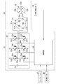
- the motor control device 33 includes an inverter 52 and a control unit 54.
- the inverter 52 includes six switching elements 52a to 52f connected by a three-phase bridge, and diodes 53a to 53f connected in antiparallel between the collectors and emitters of the switching elements 52a to 52f.
- Each of the switching elements 52a to 52f is, for example, a FET (Field Effect Transistor) or an IGBT (Insulated Gate Bipolar Transistor).
- Each gate of the six bridge-connected switching elements 52a to 52f is connected to the control unit 54.
- the drain or source (collector or emitter) of the switching elements 52a to 52f is connected to the delta-connected armature coils 21u, 21v, 21w. More specifically, the neutral point 55a, which is the connection point between the source of the switching element 52a and the drain of the switching element 52d, is connected to the connection point 21a of the armature coil 21w and the armature coil 21u. The neutral point 55b, which is the connection point between the source of the switching element 52b and the drain of the switching element 52e, is connected to the connection point 21b of the armature coil 21w and the armature coil 21v.
- the neutral point 55c which is the connection point between the source of the switching element 52c and the drain of the switching element 52f, is connected to the connection point 21c of the armature coil 21v and the armature coil 21u.
- the six switching elements 52a to 52f perform a switching operation based on the drive signal (gate signal) output from the control unit 54, and the power supply voltage of the DC power supply 51 applied to the inverter 52 is set to three phases.
- an AC voltage of (U phase, V phase, W phase) it is supplied as an energization signal to the armature coils 21u, 21v, 21w.
- the control unit 54 determines the rotation position of the rotor 22 based on the pulse signal supplied from the rotation angle detection unit 39. Further, the control unit 54 detects the rotation speed of the rotor 22 based on the pulse signal. Then, the control unit 54 drives the brushless motor 30 in a sine wave in a low output mode in which the output of the brushless motor 30 is low. That is, by outputting the first drive signal to the inverter 52, the control unit 54 energizes the armature coils 21u, 21v, 21w by the sine wave (first energization signal) in which harmonics are superimposed on the sine wave. , The rotor 22 is rotationally driven.
- the first drive signal corresponds to the first energization signal.
- control unit 54 outputs the first drive signal as an instruction signal for controlling the inverter 52. Then, the inverter 52 drives each of the three phases in a sine wave by the first energization signal based on the instruction signal (details will be described later with reference to FIG. 6).
- the control unit 54 outputs the second drive signal to the inverter 52 in the high output mode in which the output is higher than the low output mode, so that the armature coils 21u, 21v, 21w and the first energization signal are wide-angle trapezoidal.
- the rotor 22 is rotationally driven by energizing with a waved sine wave (second energization signal).
- the second drive signal corresponds to the second energization signal. That is, the control unit 54 outputs the second drive signal as an instruction signal for controlling the inverter 52. Then, the inverter 52 drives each of the three phases in a sine wave by the second energization signal based on the instruction signal (details will be described later with reference to FIG. 7).
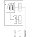
- FIG. 5 is a diagram showing an example of a schematic configuration of the control unit 54 in the present embodiment.
- the control unit 54 includes a position detection unit 61, a load determination unit 62, a mode determination unit 63, and a drive control unit 64.
- the position detection unit 61 detects the rotation position of the rotor 22 based on the pulse signal supplied from the rotation angle detection unit 39.
- the position detection unit 61 outputs the detected rotation position of the rotor 22 to the drive control unit 64.
- the load determination unit 62 determines whether or not the vehicle speed V measured by the vehicle speed sensor 40 exceeds a preset predetermined value Vth.
- the load determination unit 62 determines that the load of the brushless motor 30 is a high load when the vehicle speed V measured by the vehicle speed sensor 40 exceeds a predetermined value Vth.
- the load determination unit 62 outputs a high load signal indicating the determination result to the mode determination unit 63. This is because when the vehicle speed V of the vehicle 10 increases, the air volume of the vehicle 10 to the windshield 11 increases, and the movement of the wiper blades 17 and 18 that wipe the windshield 11 is hindered.
- the brushless motor 30 needs to swing the wiper arms 14 and 16 at high output. Therefore, when the vehicle speed V exceeds the predetermined value Vth, the control unit 54 shifts from the low output mode to the high output mode to generate a large torque for the brushless motor 30, and the position detection unit 61 detects it.
- the rotation speed of the brushless motor 30 is increased by controlling the advance angle at a predetermined electric angle with reference to the rotation position of the rotor 22.
- the load determination unit 62 is a predetermined value calculated from a predetermined value of the rotation speed of the rotor 22 and the current value of the brushless motor 30 detected based on the pulse signal supplied from the rotation angle detection unit 39, or both. Determines whether or not exceeds a preset predetermined value.
- the load determination unit 62 has a predetermined value calculated from the rotation speed of the rotor 22 and / or the current value of the brushless motor 30 detected based on the pulse signal supplied from the rotation angle detection unit 39. When the preset value exceeds a preset value, it is determined that the load of the brushless motor 30 is high.
- the load determination unit 62 determines that the load of the brushless motor 30 is a high load
- the load determination unit 62 outputs a high load signal indicating the determination result to the mode determination unit 63. This is because changes in conditions such as changes in rainfall occur, resistance to movement of the wiper blades 17 and 18 on the windshield 11 (wiping surface) of the vehicle 10 increases, and movement of the wiper blades 17 and 18 is hindered. Is. In this case, the brushless motor 30 needs to swing the wiper arms 14 and 16 at high output.
- the control unit 54 increases from the low output mode to the high value.
- the brushless motor is controlled at a predetermined electric angle based on the rotation position of the rotor 22 detected by the position detection unit 61. Increase the number of revolutions of 30.
- the mode determination unit 63 determines whether the brushless motor 30 is driven in the low output mode, the high output mode, or the brushless motor 30 is stopped. When the mode determination unit 63 acquires the low-speed operation mode signal from the wiper switch 37, it determines that the brushless motor 30 is driven in the low output mode, and outputs a low output mode signal indicating the low output mode to the drive control unit 64. .. When the high-speed operation mode signal is acquired from the wiper switch 37, the mode determination unit 63 determines that the brushless motor 30 is driven in the high output mode, and outputs a high output mode signal indicating the high output mode to the drive control unit 64. .. Further, the mode determination unit 63 determines that the brushless motor 30 is driven in the high output mode when the high load signal is acquired from the load determination unit 62, and transmits the high output mode signal indicating the high output mode to the drive control unit 64. Output.
- the mode determination unit 63 determines to stop the drive of the brushless motor 30, and outputs a stop signal indicating the stop of the drive of the brushless motor 30 to the drive control unit 64. ..
- the drive control unit 64 includes a first drive control unit 641 and a second drive control unit 642.
- the drive control unit 64 executes the third harmonic energization drive of the brushless motor 30 by the first drive control unit 641.
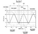
- FIG. 6 is a timing chart showing the energization timings of the U, V, and W phases by the first drive control unit 641 in the present embodiment.
- the angle from 0 ° to 360 ° shown on the horizontal axis of FIG. 6 is an electric angle representing an energization period within one cycle of the first energization signal.
- FET_DUTY [%] shown on the vertical axis represents the duty of the applied voltage applied to each phase.
- the first energization signal represents the applied voltage of each of the three phases in which the third harmonic is superimposed on the sine wave. That is, in the first control mode, the inverter 52 is the first energization timing indicating the energization timing of each of the three phases in which the third harmonic is superimposed on the sine wave at the energization timing according to the rotation position of the rotor. It outputs a signal and drives each of the three phases of the brushless motor in a sine wave.
- the drive control for energizing the brushless motor 30 by the first energization signal may be referred to as a third harmonic energization drive.
- the first drive control unit 641 outputs the first drive signal to the inverter 52 at the energization timing corresponding to the rotation position of the rotor 22 detected by the position detection unit 61, so that the first drive control unit 641 can contact the inverter 52.
- a first energization signal for driving the brushless motor 30 by energizing the third harmonic is generated.
- the first energization signal has a waveform in which a third harmonic is superimposed on a sine wave (hereinafter, referred to as a third harmonic superimposed wave).
- the duty (peak voltage) of the applied voltage at the peak of the waveform is about 100% (97 to 99%) in a certain section, and the duty of the applied voltage at the valley is about 0% (1 to 1 to). 3%).
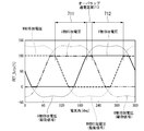
- 7A to 7D are timing charts showing the energization timings of the U, V, and W phases by the second drive control unit 642 in the present embodiment.
- the angles from 0 ° to 360 ° shown on the horizontal axis of FIGS. 7A to 7D are electric angles representing the energization period within one cycle of the second energization signal.
- FET_DUTY [%] shown on the vertical axis represents the duty of the applied voltage applied to each phase.
- the second energization signal is the energization timing according to the rotation position of the rotor 22 (rotor), and only the duty of the applied voltage of the first phase out of the three phases is the duty. Between the normal energization section where the duty is 100% and the normal energization section where only the duty of the applied voltage of the second phase is 100%, the duty of the applied voltage of the first phase and the second phase is 100%. It is a signal including an overlap energization section which becomes a duty (described later with reference to FIGS. 7A to 7D). For example, in the first energization signal shown in FIG.
- the section is set as an overlap energization section (voltage value overlapping section) in which the applied voltages of both the W phase and the U phase are also 100% duty.
- the overlap energization section is also set between the other phases (between the U phase and the V phase and between the V phase and the W phase).
- the second energization signal includes only the energization section (normal energization section 731) in which only the duty of the applied voltage of the V phase of the three phases is 100% and the duty of the applied voltage of the W phase.
- the second energization signal includes only the energization section (normal energization section 751) in which only the duty of the applied voltage of the W phase of the three phases is 100% and the duty of the applied voltage of the U phase.
- the second energization signal is 100% only in the normal energization section in which only the duty of the applied voltage of the first phase of the three phases is 100% and the duty of the applied voltage of the second phase. It has been described that the signal includes an overlapping energization section in which the duty of the applied voltage of the first phase and the second phase is 100% of the duty of the normal energization section.
- the second energization signal is the energization section (normal energization section 701) in which only the duty of the applied voltage of the U phase is 0% of the three phases and the applied voltage of the V phase.
- energization section 703 overlap energization section 703 in which the duty of the applied voltage of the U phase and the V phase is both 0% between the energization section (normal energization section 702) in which only the duty is 0%.
- the second energization signal only the energization section (normal energization section) in which only the duty of the applied voltage of the V phase is 0% and the duty of the applied voltage of the W phase are 0%.
- energized section overlap energized section between the energized section (normal energized section) and the duty of the applied voltage of the V phase and the W phase is 0%.
- the second energization signal includes an energization section in which only the duty of the applied voltage of the W phase is 0% (normal energization section) and an energization section in which only the duty of the applied voltage of the U phase is 0% (normally). There is an energized section (overlapping energized section) between the energized section) and the duty of the applied voltage of the W phase and the U phase is 0%.
- the drive control for energizing the brushless motor 30 by the second energization signal may be referred to as a wide-angle trapezoidal wave energization drive.
- the second drive control unit 642 outputs the second drive signal to the inverter 52 at the energization timing corresponding to the rotation position of the rotor 22 detected by the position detection unit 61, so that the second drive control unit 642 can transmit the second drive signal to the inverter 52.
- a second energization signal for driving the brushless motor 30 with a wide-angle trapezoidal wave energization is generated.
- driving the brushless motor 30 with a wide-angle trapezoidal wave energization significantly improves the output characteristics of the motor as compared with driving the brushless motor 30 with a third harmonic energization in the low output mode. This is because (hereinafter referred to as purpose 1). Further, in the high output mode, driving the brushless motor 30 with a wide-angle trapezoidal wave energization is different from driving the brushless motor 30 with a rectangular wave (wide-angle energization drive in Patent Documents 1 and 2) in the high output mode. This is because it is possible to suppress the operating noise (hereinafter referred to as the purpose 2).
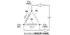
- FIG. 8 is a diagram for explaining the principle of improving the output characteristics of the motor by providing the overlap energization section in the second energization signal.
- the resistor RW, resistor RU, and resistor RV shown in FIG. 8 are circuits composed of switching elements 52a to 52f of the inverter 52 and three-phase armature coils 21u, 21v, and 21w, respectively (referred to as a resistor circuit). It shall indicate the reference resistance in. Further, the size of the arrow shown in FIG. 8 is proportional to the size of the value of the current applied to each phase.
- FIG. 8A is a circuit diagram in an energized state near an electric angle of 180 ° in FIG. 7D (reference numeral 800a in FIG. 7D).
- the duty of the W phase applied voltage is 100% at the connection point 21a
- the duty of the V phase applied voltage is 0% at the connection point 21b
- the duty of the U phase applied voltage is at the connection point 21c. It is energized at 50%.
- FIG. 8A when driving in the normal energization section (three-phase energization) in the high output mode, all three phases are energized, so that the resistance Ra between terminals in the resistance circuit is the resistance RW (resistance).
- Ra 2R / 3 according to the following equation.
- R The resistance Ra between terminals in the resistance circuit means a resistance value between the positive electrode terminal and the negative electrode terminal of the DC power supply 51 shown in FIG.
- the current flowing through the resistor RW is the series resistance of the resistor RU and the resistor RV. It is larger than the flowing current.
- FIG. 8B is a circuit diagram in an energized state in the vicinity of an electric angle of 210 ° in FIG. 7A (reference numeral 800b in FIG. 7A).
- the inter-terminal resistance Rb in the resistance circuit means a resistance value between the positive electrode terminal and the negative electrode terminal of the DC power supply 51 shown in FIG.
- a current flows through the resistor RW and the resistor RV, but almost no current flows through the resistor RU.
- an applied voltage of 100% duty is applied to the connection point 21a and the connection point 21c, and an applied voltage of 0% duty is applied to the connection point 21b. Therefore, the connection point 21a and the connection point 21c have the same potential, and no current flows between the connection point 21a and the connection point 21c.
- connection point 21a and the connection point 21b and the potential difference between the connection point 21c and the connection point 21b become equal, and the current flowing between the connection point 21a and the connection point 21b and the connection point The current flowing between the 21c and the connection point 21b becomes equal.
- the magnitude of the current flowing through the resistor RW and the magnitude of the current flowing through the resistor RV are almost the same, but the current hardly flows through the resistor RU, and the brushless motor 30 affects the resistance value of the resistor RU. I will not receive it.
- the circuit to be energized changes from 3 phase to 2 phase, and the resistance calculation result changes from 2R / 3 to R / 2, so that the motor internal resistance is changed to (2R / 3).
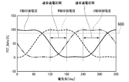
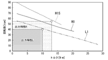
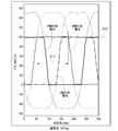
- FIG. 9 is a diagram showing the motor characteristics of the brushless motor 30 in the third harmonic energization drive and the wide-angle trapezoidal wave energization drive in the present embodiment.
- L1 shows the motor characteristics of the third harmonic energization drive.
- H1 shows the motor characteristics of the wide-angle trapezoidal wave energization drive.
- H1S shows the motor characteristics of a wide-angle trapezoidal wave + "advance angle> 0 °" energized drive.
- the wide-angle trapezoidal wave + "advance angle> 0 °" energization drive outputs a second energization signal at an energization timing in which a predetermined electric angle is advanced with reference to the rotation position of the rotor 22, and the brushless motor Wide-angle trapezoidal wave energization drive that drives each of the three phases with a sine wave.
- the region indicated by the output characteristic L indicates the motor characteristics in the one-wiping cycle required in the low-speed operation mode at a low vehicle speed.
- the region indicated by the output characteristic H indicates the motor characteristics in the one-wiping cycle required for the high-speed operation mode during high-speed running. As shown in FIG.
- the drive control unit 64 can satisfy the motor characteristics in the one-wiping cycle required in the low-speed operation mode by performing the third-order harmonic energization drive in the low output mode. Further, the drive control unit 64 executes wide-angle trapezoidal wave energization drive when the mode shifts from the low output mode to the high output mode. That is, the drive control unit 64 reduces the rotation speed of the brushless motor 30 by the wide-angle trapezoidal wave energization drive and the wide-angle trapezoidal wave + "advance angle> 0 °" energization drive as compared with the third harmonic energization drive in the low output mode.
- the drive control unit 64 satisfies the motor characteristics in the one-wiping cycle required in the high-speed operation mode by performing wide-angle trapezoidal wave energization drive or wide-angle trapezoidal wave + "advance angle> 0 °" energization drive. be able to.
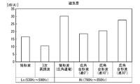
- FIG. 10 and 11 are diagrams showing the characteristics of the operating noise of the brushless motor 30 in the drive control used in the low output mode or the high output mode.
- FIG. 10 shows that the drive control of the brushless motor 30 is performed by the following six drive controls (1st to 6th drive controls) in the low (Lo) output mode or the high (Hi) output mode to obtain the rotation frequency of the rotor 22.
- the corresponding operating sound is FFT (Fast) in the frequency band (0 to 15 KHz). Fourier Transform) It shows the A (Over All) value.
- O The A value is a value used when simply evaluating whether the sound is noisy or quiet without paying attention to the frequency characteristics.
- FIG. 10 shows that the drive control of the brushless motor 30 is performed by the following six drive controls (1st to 6th drive controls) in the low (Lo) output mode or the high (Hi) output mode to obtain the rotation frequency of the rotor 22.
- the corresponding operating sound is FFT (Fast) in the frequency band (0 to
- the drive control of the brushless motor 30 is performed by the following six drive controls (first to sixth drive controls) in the low output mode or the high output mode, and the operating sound corresponding to the rotation frequency of the rotor 22.
- the magnetic sound is measured when the rotation frequency of the rotor 22 is 530 Hz to 590 Hz (Lo output mode) or when the rotation frequency is 790 Hz to 850 Hz (Hi output mode).
- the first drive control is a drive control performed by a rectangular wave drive in the low output mode, and corresponds to the rectangular wave drive of Patent Document 1.
- the second drive control is a drive control performed by a third harmonic drive (sine wave drive) in the low output mode, and is supported by Patent Document 2 and the sine wave drive of the present embodiment.
- the third drive control is a drive control performed by rectangular wave energization (wide-angle energization) in the high output mode, and corresponds to the rectangular wave drive of Patent Document 2.
- the fourth drive control is a drive control performed by a wide-angle trapezoidal wave energization drive (sine wave drive) in the high output mode, and corresponds to the sine wave drive of the present embodiment.
- the fifth drive control is a drive control performed by a wide-angle trapezoidal wave + energization drive (sine wave drive) of "advance angle 10 °" in the high output mode, and corresponds to the sine wave drive of the present embodiment.
- the sixth drive control is a drive control performed by a wide-angle trapezoidal wave + energization drive (sine wave drive) of "advance angle 30 °" in the high output mode, and corresponds to the sine wave drive of the present embodiment.
- the drive control is performed by the wide-angle trapezoidal wave energization drive in the high output mode, and the drive control is performed by the square wave energization (wide-angle energization) in the high output mode (square wave energization of Patent Document 2). (Wide-angle energization)), the operating noise can be suppressed. That is, it can be said that the above object 2 has been achieved.
- the drive control unit 64 When the drive control unit 64 acquires a stop signal from the mode determination unit 63, the drive control unit 64 stops the drive of the brushless motor 30 by the first drive control unit 641 or the second drive control unit 642. That is, when the drive control unit 64 acquires the stop signal from the mode determination unit 63, the drive control unit 64 stops the drive of the brushless motor 30 and stops the swinging operation of the wiper arms 14 and 16.
- the inverter 52 generates a second energization signal in the high output mode.
- the duty of the applied voltage applied from the inverter 52 to each phase of the armature coils 21u, 21v, 21w is set to FET_Duty [%], and the control unit 54 (second drive control unit 642) applies to the inverter 52.
- the duty indicated by the command value of the applied voltage applied to each phase by the inverter 52 included in the output instruction signal is expressed as Software_Duty [%].
- the motor control device 33 has a FET_Duty of about 100% at the peak of the third harmonic superimposed wave and a FET_Duty of about 0% at the valley, as shown in FIG. It is set.
- the second energization signal is a wide-angle trapezoidal wave. That is, in the second energization signal, in the waveform in which the amplitude of the first energization signal is changed to a value larger than 50% in FET_Duty, the energization section in which FET_Duty is 100% or more has FET_Duty of 100% and FET_Duty.
- the energized section of 0% or less is a waveform with FET_Duty set to 0%.
- the motor control device 33 has a FET_Duty value larger than 100% in the peak of the third harmonic superimposed wave (for example, a duty exceeding 100% and a range of up to about 130%).
- the duty is set to be less than 0% in the valley (for example, the duty is less than 0% and any duty in the range up to about -30%). .
- FIG. 12 is a timing chart showing the energization timings of the U, V, and W phases by the second drive control unit 642 in the present embodiment.
- FIG. 13 is a timing chart showing variations of the software (software) in the present embodiment.
- the angles from 0 ° to 360 ° shown on the horizontal axes of FIGS. 12 and 13 are electric angles representing the energization period within one cycle of the second energization signal as in FIGS. 7A to 7D.
- the first vertical axis (the vertical axis on the left side in the figure) represents FET_Duty [%].
- the second vertical axis (vertical axis on the right side in the figure) represents software_Duty [%].
- FIG. 12 is recognized by the software (software) used when the inverter 52 performs the control operation by the command of the control unit 54 and the FET that applies the applied voltage to each of the U, V, and W phases.
- An example is shown when the scales are different.
- FET_Duty [%] 80 to 100%
- FET_Duty [%] 100 to 130%
- the apparent FET_Duty [%] (duty of the applied voltage actually applied to each phase) is It is 100% as shown by the thick line in FIG.
- FIG. 13 shows an example in which the software (software) used when the inverter 52 performs the control operation by the command of the control unit 54 is capable of outputting 100% or more of the duty.
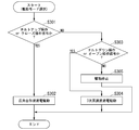
- FIG. 14 is a diagram illustrating a processing flow of the control unit 54 in the present embodiment.
- FIG. 15 is a diagram illustrating a modified example of FIG. 14 in the present embodiment.
- the control unit 54 determines whether or not the wiper switch 37 has been operated by the driver on the low-speed operation side (step S101). For example, when the control unit 54 acquires the low-speed operation mode signal from the wiper switch 37, the control unit 54 determines that the wiper switch 37 has been operated to the low-speed operation side. When the wiper switch 37 is operated to the low-speed operation side by the driver, the control unit 54 drives the brushless motor 30 to energize the third harmonic (step S102).
- the control unit 54 determines whether or not the wiper switch 37 is operated on the high speed operation side (step S103). For example, when the control unit 54 acquires the high-speed operation mode signal from the wiper switch 37, the control unit 54 determines that the wiper switch 37 has been operated to the high-speed operation side.
- the control unit 54 drives the brushless motor 30 with a wide-angle trapezoidal wave energization when the wiper switch 37 is operated to the high-speed operation side by the driver (step S104).
- the processing flow of the control unit 54 in the present embodiment shown in FIG. 14 may be the processing flow of the control unit 54 shown in FIG.
- the control unit 54 determines whether or not the wiper switch 37 has been operated by the driver on the low-speed operation side (step S201). For example, when the control unit 54 acquires the low-speed operation mode signal from the wiper switch 37, the control unit 54 determines that the wiper switch 37 has been operated to the low-speed operation side. The control unit 54 determines whether or not the high output mode is necessary when the wiper switch 37 is operated to the low speed operation side by the driver (step S202). When the control unit 54 determines that the high output mode is not necessary, the control unit 54 drives the brushless motor 30 to energize the third harmonic (step S203).
- the control unit 54 determines whether or not the wiper switch 37 is operated on the high speed operation side (step S204). For example, when the control unit 54 acquires the high-speed operation mode signal from the wiper switch 37, the control unit 54 determines that the wiper switch 37 has been operated to the high-speed operation side. The control unit 54 determines whether or not the high output mode is necessary when the wiper switch 37 is operated by the driver to the high-speed operation side (step S205). When the control unit 54 determines that the high output mode is necessary, the control unit 54 drives the brushless motor 30 by energizing a wide-angle trapezoidal wave (step S206).
- control unit 54 determines that the wiper switch 37 has been operated to the low speed operation side in the process of step S201 and determines that the high output mode is necessary in the process of step S202
- the control unit 54 causes the brushless motor 30 to have a wide-angle trapezoidal wave. Energized drive.
- the brushless motor 30 is tertiary. Harmonic energization drive.
- control unit 54 can appropriately switch between the low output mode and the high output mode regardless of whether the wiper switch 37 is on the low speed operation side or the high speed operation side. This makes it possible to respond to changes in the external environment such as changes in rainfall and changes in the conditions on the windshield 11 (wiping surface) due to changes in vehicle speed.
- the motor control device 33 drives the brushless motor 30 to energize the third harmonic in the low output mode in which the output of the brushless motor 30 is low, and the output is higher than the low output mode in the high output mode.
- the brushless motor 30 is energized by a wide-angle trapezoidal wave energization drive.
- the motor control device 33 is driven by the third harmonic energization drive in the frequently used low-speed operation mode, so that the operation noise is more efficient than the rectangular wave energization control described in Patent Document 1. It can be reduced (see FIG. 11).
- the motor control device 33 is driven by wide-angle trapezoidal wave energization to further improve the motor characteristics as compared with the sine wave drive in the low-speed operation mode, and is required in the high-speed operation mode.
- the motor characteristics to be achieved can be satisfied (see FIG. 9).
- the rectangular wave energization control (wide-angle energization drive) described in Patent Document 2 it is possible to efficiently reduce the operating noise (see FIG. 11).
- the motor unit 19 including the brushless motor 30 which is a brushless wiper motor for swinging the wiper arm and the motor control device 33 has been described. It may be a motor unit composed of the following brushless motor and motor control device.
- a brushless motor which is a brushless sunroof motor that opens and closes the roof panel provided on the roof of the vehicle, and a motor control to which the switching control in the present embodiment is applied according to when the vehicle is stopped (low load) and when the vehicle is running (high load).
- a sunroof motor unit consisting of a device.
- the brushless motor which is a brushless power seat motor that drives the vehicle seat, and the fine adjustment of the seat position (seat position, angle adjustment) perform energization drive by the first energization signal (applied voltage), and the seat position is significantly changed (seat position, angle adjustment).
- a power seat consisting of a motor control device that performs energization drive by a second energization signal (applied voltage) and controls switching between both energizations. Motor unit.
- a brushless motor which is a brushless fan motor used as a drive source for a radiator cooling device of a vehicle, and a brushless motor, which corresponds to variable speed, are driven by a first energization signal and a second energization signal to control switching between both energizations.
- a fan motor unit consisting of a motor control device to perform.
- Power slide door motor unit A brushless power slide door motor used as an electric motor for opening and closing the sliding door of a vehicle, and a motor control device that performs energization drive by a first energization signal and a second energization signal and controls switching between both energizations. Power slide door motor unit composed of.
- the sunroof unit includes a sunroof and a sunroof operator that opens and closes the sunroof.
- the control unit 54 acquires an operation signal corresponding to the operation of the sunroof operator from the sunroof operator, and opens and closes the sunroof according to the acquired operation signal.
- the sunroof operator may be, for example, a switch that specifies which operation of opening / closing is performed, or an operation panel such as a touch panel.
- FIG. 16 is a diagram illustrating a modified example of the processing flow of the control unit 54 when the motor unit 19 is applied to the sunroof unit.
- the control unit 54 acquires an operation signal from the sunroof operator, and the acquired operation signal is an operation signal for performing a tilt-up operation or an operation signal for performing a close operation. Whether or not it is determined (step S301).
- the control unit 54 drives the brushless motor 30 with a wide-angle trapezoidal wave energization for the tilt-up operation or the close operation. (Step S302).
- the operation signal indicates a tilt-up operation
- the motor unit 19 is driven by a wide-angle trapezoidal wave energization to perform the tilt-up operation.
- the operation signal indicates a close operation
- the motor unit 19 is driven by a wide-angle trapezoidal wave energization to perform the close operation.
- the tilt-up operation is, for example, an operation in which the sunroof is tilted upward to open
- the closing operation is an operation in which the sunroof is closed.
- step S301 when the operation signal is not an operation signal for performing a tilt-up operation or an operation signal for performing a close operation (step S301-NO), the control unit 54 determines that the operation signal is an operation signal for performing a tilt-down operation or open. It is determined whether the operation signal is to be operated (step S303). When the operation signal is an operation signal for performing a tilt-down operation or an operation signal for performing an open operation (step S303-YES), the control unit 54 performs a tilt-down operation or an open operation to drive the motor unit 19 to a third harmonic energization. (Step S304).
- the control unit 54 performs the tilt-down operation by driving the motor unit 19 to energize the third harmonic.
- the control unit 54 performs an open operation by driving the motor unit 19 with a third harmonic energization.
- the tilt-down operation is an operation of closing the sunroof by returning the tilt of the tilted-up sunroof to its original position
- an open operation is an operation of opening the sunroof by moving it to a fully open position.
- step S303 when the operation signal is not the operation signal for tilting down operation or the operation signal for opening operation (step S303-NO), the control unit 54 has made an unexpected operation input, such as failure or emergency. It is determined that the drive is stopped or the like, and the drive is stopped (step S305). As described above, the control unit 54 performs the wide-angle trapezoidal wave energization drive in the tilt-up operation or the close operation, and performs the third harmonic energization drive in the tilt-down operation or the open operation.
- the motor unit 19 can be smoothly operated even in such a situation.
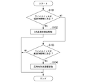
- FIG. 17 is a diagram illustrating a modified example of the processing flow of the control unit 54 when the motor unit 19 is applied to the sunroof unit.
- the control unit 54 acquires an operation signal from the sunroof operator, and whether the acquired operation signal is an operation signal for tilting up operation or an operation signal for closing operation. It is determined whether or not (step S311).
- the control unit 54 drives the brushless motor 30 with a wide-angle trapezoidal wave energization for the tilt-up operation or the close operation. (Step S312).
- the control unit 54 performs the tilt-up operation by driving the motor unit 19 with a wide-angle trapezoidal wave energization.
- the motor unit 19 is driven by a wide-angle trapezoidal wave energization to perform the close operation.
- step S311 when the operation signal is not an operation signal for performing a tilt-up operation or an operation signal for performing a close operation (step S311-NO), the control unit 54 performs an operation according to the operation content to the motor unit 19. This is executed by driving the third harmonic energization (step S314).
- step S3114 there are only four types of operation contents, “tilt up”, “close”, “chilled down”, and “open”, and when accepting any operation input among them, it is determined as NO in step S311. If this is the case, either "tilt down” or "open” operation may be executed. Therefore, the control unit 54 can perform a tilt-down operation or an open operation by performing a third-order harmonic energization drive when the operation is determined to be NO in step S311.
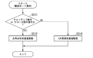
- FIG. 18 is a diagram illustrating a modified example of the processing flow of the control unit 54 when the motor unit 19 is applied to the sunroof unit.
- the control unit 54 acquires an operation signal from the sunroof operator, and whether the acquired operation signal is an operation signal for tilting up operation or an operation signal for closing operation. It is determined whether or not (step S321).
- the control unit 54 detects the vehicle speed or the load of the brushless motor 30 of the motor unit 19, and uses the detection result as a result. Based on this, it is determined whether or not the high output mode is required (step S322). In this determination, for example, it is determined whether or not the vehicle speed exceeds the vehicle speed reference value, or whether or not the load of the brushless motor 30 exceeds the load reference value. This determination may be made based on only one of them.
- the vehicle speed reference value and the load reference value may be stored in advance in a storage device inside or outside the control unit 54, and may be referred to.
- the control unit 54 determines that the high output mode is necessary when the vehicle speed exceeds the vehicle speed reference value, or when the load of the brushless motor 30 exceeds the load reference value (step S322-YES), and tilts.
- the up operation or the close operation is executed by driving the brushless motor 30 with a wide-angle trapezoidal wave energization (step S322).
- the control unit 54 performs the tilt-up operation by driving the motor unit 19 with a wide-angle trapezoidal wave energization.
- the operation signal indicates a close operation
- the motor unit 19 is driven by a wide-angle trapezoidal wave energization to perform the close operation.
- the control unit 54 determines that the high output mode is not necessary when the vehicle speed does not exceed the vehicle speed reference value or when the load of the brushless motor 30 does not exceed the load reference value (step S322-NO).
- the tilt-up operation or the close operation is executed by driving the brushless motor 30 to energize the third harmonic (step S326).
- the control unit 54 performs the tilt-up operation by driving the motor unit 19 to energize the third harmonic.
- the motor unit 19 is driven to energize the third harmonic to perform the close operation.
- step S321 when the operation signal is not an operation signal for performing a tilt-up operation or an operation signal for performing a close operation (step S321-NO), the control unit 54 determines that the operation signal is an operation signal for performing a tilt-down operation or open. It is determined whether the operation signal is to be operated (step S324). When the operation signal is an operation signal for tilting down operation or an operation signal for performing open operation (step S324-YES), the vehicle speed or the load of the brushless motor 30 of the motor unit 19 is detected, and a high output is obtained based on the detection result. It is determined whether or not the mode is in a required state (step S325).
- the control unit 54 determines that the high output mode is necessary when the vehicle speed exceeds the vehicle speed reference value, or when the load of the brushless motor 30 exceeds the load reference value (step S325-YES), and tilts.
- the down operation or the open operation is executed by driving the brushless motor 30 with a wide-angle trapezoidal wave energization (step S323).
- the control unit 54 performs the tilt-down operation by driving the motor unit 19 with a wide-angle trapezoidal wave energization.
- the operation signal indicates an open operation
- the motor unit 19 is driven by a wide-angle trapezoidal wave energization to perform the open operation.
- the control unit 54 determines that the high output mode is not necessary when the vehicle speed does not exceed the vehicle speed reference value or when the load of the brushless motor 30 does not exceed the load reference value (step S325-NO). , The control unit 54 executes the tilt-down operation or the open operation by driving the motor unit 19 to energize the third harmonic (step S326). As a result, when the operation signal indicates a tilt-down operation, the control unit 54 performs the tilt-down operation by driving the motor unit 19 to energize the third harmonic. When the operation signal indicates an open operation, the control unit 54 performs an open operation by driving the motor unit 19 with a third harmonic energization.
- step S324 when the operation signal is not an operation signal for performing a tilt-down operation or an operation signal for performing an open operation (step S324-NO), the control unit 54 has made an unexpected operation input, such as a failure or an emergency. It is determined that the drive is stopped or the like, and the drive is stopped (step S325). As described above, the control unit 54 can drive the motor unit 19 by the third harmonic energization drive if the high output mode is not required even when the tilt-up operation or the close operation is performed. Further, the control unit 54 can perform wide-angle trapezoidal wave energization drive if a high output mode is required even in the tilt-down operation or the open operation.
- FIG. 19 is a diagram illustrating a modified example of the processing flow of the control unit 54 when the motor unit 19 is applied to the sunroof unit.
- the control unit 54 acquires an operation signal from the sunroof operator, and whether the acquired operation signal is an operation signal for tilting up operation or an operation signal for closing operation. It is determined whether or not (step S331).
- the control unit 54 detects the vehicle speed or the load of the brushless motor 30 of the motor unit 19, and uses the detection result as a result. Based on this, it is determined whether or not the high output mode is required (step S332). In this determination, for example, it is determined whether or not the vehicle speed exceeds the vehicle speed reference value, or whether or not the load of the brushless motor 30 exceeds the load reference value. This determination may be made based on only one of them.
- the vehicle speed reference value and the load reference value may be stored in advance in a storage device inside or outside the control unit 54, and may be referred to.
- the control unit 54 determines that the high output mode is necessary when the vehicle speed exceeds the vehicle speed reference value, or when the load of the brushless motor 30 exceeds the load reference value (step S332-YES), and tilts.
- the up operation or the close operation is executed by driving the brushless motor 30 with a wide-angle trapezoidal wave energization (step S333).
- the control unit 54 performs the tilt-up operation by driving the motor unit 19 with a wide-angle trapezoidal wave energization.
- the operation signal indicates a close operation
- the motor unit 19 is driven by a wide-angle trapezoidal wave energization to perform the close operation.
- the control unit 54 determines that the high output mode is not necessary when the vehicle speed does not exceed the vehicle speed reference value or when the load of the brushless motor 30 does not exceed the load reference value (step S332-NO).
- the tilt-up operation or the close operation is executed by driving the brushless motor 30 to energize the third harmonic (step S335).
- the control unit 54 performs the tilt-up operation by driving the motor unit 19 to energize the third harmonic.
- the motor unit 19 is driven to energize the third harmonic to perform the close operation.
- the third harmonic energization drive even in the tilt-up operation and the close operation, if it is not necessary to be in the high output mode, it can be driven by the third harmonic energization drive.
- step S331 when the operation signal is not an operation signal for tilting up operation or an operation signal for closing operation (step S331-NO), the control unit 54 applies the vehicle speed or the load of the brushless motor 30 of the motor unit 19. It is detected, and based on the detection result, it is determined whether or not the high output mode is required (step S334).
- the control unit 54 determines that the high output mode is necessary when the vehicle speed exceeds the vehicle speed reference value, or when the load of the brushless motor 30 exceeds the load reference value (step S334-YES), and tilts.
- the down operation or the open operation is executed by driving the brushless motor 30 with a wide-angle trapezoidal wave energization (step S333).
- the control unit 54 performs the tilt-down operation by driving the motor unit 19 with a wide-angle trapezoidal wave energization.
- the control unit 54 performs an open operation by driving the motor unit 19 with a wide-angle trapezoidal wave energization.
- the control unit 54 determines that the high output mode is not necessary when the vehicle speed does not exceed the vehicle speed reference value or when the load of the brushless motor 30 does not exceed the load reference value (step S334-NO). , The control unit 54 executes the tilt-down operation or the open operation by driving the motor unit 19 to energize the third harmonic (step S326). As a result, when the operation signal indicates a tilt-down operation, the control unit 54 performs the tilt-down operation by driving the motor unit 19 to energize the third harmonic. When the operation signal indicates an open operation, the control unit 54 performs an open operation by driving the motor unit 19 with a third harmonic energization. According to this modification, when the control unit 54 determines NO in step S331, it is not necessary to perform the determination step as to whether it is the tilt-down operation or the open operation shown in step S324 of FIG.
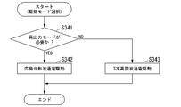
- FIG. 20 is a diagram illustrating a modified example of the processing flow of the control unit 54 when the motor unit 19 is applied to the sunroof unit.
- the control unit 54 acquires an operation signal from the sunroof operator, detects the vehicle speed or the load of the brushless motor 30 of the motor unit 19, and outputs a high output based on the detection result. It is determined whether or not the mode is in a required state (step S341). In this determination, for example, it is determined whether or not the vehicle speed exceeds the vehicle speed reference value, or whether or not the load of the brushless motor 30 exceeds the load reference value. This determination may be made based on only one of them.
- the vehicle speed reference value and the load reference value may be stored in advance in a storage device inside or outside the control unit 54, and may be referred to.
- the control unit 54 determines that the high output mode is necessary when the vehicle speed exceeds the vehicle speed reference value, or when the load of the brushless motor 30 exceeds the load reference value (step S341-YES), and operates.
- the operation corresponding to the signal is executed by driving the brushless motor 30 with a wide-angle trapezoidal wave energization (step S342).
- the control unit 54 performs a tilt-up operation by driving the motor unit 19 with a wide-angle trapezoidal wave energization, and when the operation signal indicates a close operation, the motor unit 19 Is driven by a wide-angle trapezoidal wave energization to perform a closing operation.
- the control unit 54 performs a tilt-down operation by driving the motor unit 19 with a wide-angle trapezoidal wave energization, and when the operation signal indicates an open operation, the motor unit 19 Is driven by a wide-angle trapezoidal wave energization to perform open operation.
- the control unit 54 determines that the high output mode is not necessary when the vehicle speed does not exceed the vehicle speed reference value or when the load of the brushless motor 30 does not exceed the load reference value (step S341-NO). , The operation according to the operation signal is executed by driving the brushless motor 30 to energize the third harmonic (step S343).
- the control unit 54 performs a tilt-up operation by driving the motor unit 19 by energizing the third harmonic, and when the operation signal indicates a close operation, the motor unit The closing operation is performed by driving 19 with a third harmonic energization.
- the control unit 54 when the operation signal indicates a tilt-down operation, the control unit 54 performs a tilt-down operation by driving the motor unit 19 to energize the third harmonic, and when the operation signal indicates an open operation, the motor unit 54 performs a tilt-down operation.
- the open operation is performed by driving 19 with a third harmonic energization.
- the control unit 54 energizes the wide-angle trapezoidal wave based on the determination result of whether or not the high output mode is required, not the type of the operation content in which the sunroof operator is operated by the driver. It is possible to decide whether to perform the drive or the third harmonic energization drive. On top of that, the sunroof can be controlled according to the operation content.
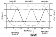
- FIGS. 21A to 21C are diagrams showing the results of experiments on the operation of the motor unit 19.
- the angles from 0 ° to 360 ° shown on the horizontal axis of FIGS. 21A to 21C are electric angles representing the energization period within one cycle of the second energization signal.
- FET_Duty [%] shown on the vertical axis represents the applied voltage applied to each phase.
- FIG. 21A is a timing chart showing the energization timings of the U, V, and W phases by the second drive control unit 642 in the present embodiment.
- 21A shows the waveform of the second energization signal, which is the applied voltage of each of the three phases in which the third harmonic is superimposed on the sine wave, and the energization section in which FET_Duty [%] is 100% or more.
- the waveform when the wide-angle trapezoidal wave is energized so that (hereinafter referred to as 100% energization angle) (reference numeral 215) is 110 ° is shown.
- the applied voltage is applied to any two of the three phases of U phase, V phase, and W phase (at least one of V phase and W phase, W phase and U phase, and U phase and V phase).
- the duty value when the duty is the same is about 90% (reference numeral 210).
- any two phases (V phase and W phase, W phase and U phase, U phase) of the three phases of U phase, V phase, and W phase are used. And at least one of the V phases), the duty value when the duty of the applied voltage becomes the same is about 80% (reference numeral 600). Therefore, the duty value when the duty of the applied voltage becomes the same is larger in the second energization signal (second control mode) than in the first energization signal (first control mode).
- FIG. 21B is a timing chart showing the energization timings of the U, V, and W phases by the second drive control unit 642 in the present embodiment.
- FIG. 21B shows the waveform of the second energization signal, and shows the waveform when the wide-angle trapezoidal wave energization drive is performed so that the 100% energization angle (reference numeral 216) is 130 °.
- the application is applied to any two of the three phases of the U phase, the V phase, and the W phase (at least one of the V phase and the W phase, the W phase and the U phase, and the U phase and the V phase).
- the duty value when the voltage duty is the same is about 100% (reference numeral 211).
- the duty value when the duty of the applied voltage is the same for any two of the three phases is about 80%.
- the duty value when the duty of the applied voltage is the same for any two of the three phases is about 100%. Therefore, the duty value when the duty of the applied voltage becomes the same is larger in the second energization signal (second control mode) than in the first energization signal (first control mode).
- FIG. 21C is a timing chart showing the energization timings of the U, V, and W phases by the second drive control unit 642 in the present embodiment.
- FIG. 21C shows the waveform of the second energization signal, and shows the waveform when the wide-angle trapezoidal wave energization drive is performed so that the 100% energization angle (reference numeral 217) is 155 °.
- the second energization signal has an overlap energization section.
- the application is applied to any two of the three phases of the U phase, the V phase, and the W phase (at least one of the V phase and the W phase, the W phase and the U phase, and the U phase and the V phase).
- the duty value when the voltage duty becomes the same is about 120% (reference numeral 212), and the apparent FET_Duty [%] of the two phases are both 100% in the overlap energization section.
- the duty value when the applied voltage duty is the same for any two of the three phases is about 80.
- the duty value when the duty of the applied voltage is the same for any two of the three phases is about 120%. Is. Therefore, the duty value when the duty of the applied voltage becomes the same is the second energization signal (first energization signal) rather than the first energization signal (first control mode) even when the energization angle is expanded to 155 °. 2 control mode) is larger.
- control unit 54 drives the second energization signal so that the current consumption and the motor output have a target balance when the 100% energization angle is controlled in the range of 110 ° to 155 °. It becomes possible. For example, when the current consumption is preferentially controlled among the current consumption and the motor output, the 100% energization angle may be set to a value closer to 110 ° in the range of 110 ° to 155 °, and 110 °. When set to, the current consumption can be further reduced. On the other hand, when controlling the current consumption and the motor output with priority given to improving the motor output, the 100% energization angle may be set to a value closer to 155 ° in the range of 110 ° to 155 °. Well, when it is set to 155 °, the motor output can be further improved.
- FIG. 22 is a diagram showing the relationship between the current consumption and the 100% energization angle in the second energization signal.
- the vertical axis represents the current consumption and the horizontal axis represents the 100% energization angle.
- the current consumption was the smallest when the 100% energization angle was set to 110 °.
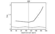
- FIG. 23 is a diagram showing the relationship between the rotation speed of the motor and the 100% energization angle when the 100% energization angle is set to 155 ° in the second energization signal.
- the vertical axis represents the rotation speed of the motor
- the horizontal axis represents the 100% energization angle.
- the rotation speed of the motor became the largest, that is, the motor output became the largest when the 100% energization angle was set to 155 °.
- the rotation speed of the motor increases as it approaches 155 °, the rotation speed becomes the largest at 155 °, and the rotation speed decreases when it exceeds 155 °.
- the retarding wave causes a drag torque (a force that tries to rotate the rotor in the opposite direction), so that the rotation speed is lower than the peak value.
- the motor control device 33 determines the rotation position of the rotor 22 based on the pulse signal supplied from the rotation angle detection unit 39, but the present invention is not limited to this.
- the motor control device 33 may determine the rotation position of the rotor 22 based on the induced voltage generated in each armature coil 21u, 21v, 21w according to the rotation of the rotor 22. This eliminates the need for the rotation angle detection unit 39 that detects the rotation position of the rotor 22, so that the number of parts and the manufacturing cost of the brushless motor 30 can be reduced.
- the wiper device 12 may include an output shaft sensor that detects at least one of the rotation speed and the absolute position of the output shaft 26.
- the absolute position is the rotation angle of the output shaft 26 with respect to the reference position.
- the reference position may be set at any position within the range of 360 degrees.
- the motor control device 33 may determine the rotation position of the rotor 22 based on the detection signal from the output shaft sensor.
- the wiper device 12 is not limited to the windshield 11 of the vehicle 10, and may wipe the rear glass. Further, the wiper device 12 may have a structure in which the wiper arms 14 and 16 swing around the output shaft 26 as a fulcrum.
- the wiper device 12 may be configured to drive the two wiper arms 14 and 16 by different brushless motors.
- the brushless motor 30 of the present embodiment may be a motor having an IPM (Interior Permanent Magnet) structure or a motor having an SPM (Surface Permanent Magnet) structure.
- the mode selected by the wiper switch 37 is not limited to two types of the low-speed operation mode and the high-speed operation mode, and may be three or more types.
- the mode selected by the wiper switch 37 may be three types, a low speed operation mode, a medium speed operation mode, and a high speed operation mode.
- the rotation speed of the rotor 22 in the medium speed operation mode is higher than the rotation speed of the rotor 22 in the low speed wiping mode, and is lower than the rotation speed of the rotor 22 in the high speed operation mode.
- the motor control device 33 may perform a third harmonic energization drive on the brushless motor 30 or a wide-angle trapezoidal wave energization drive.
- a third harmonic energization drive on the brushless motor 30 or a wide-angle trapezoidal wave energization drive.
- the wide-angle trapezoidal wave energization drive or the wide-angle trapezoidal wave + "advance angle>0" ° ” The energization drive may be performed.
- the operation mode may be changed based on the detection result from the raindrop sensor instead of the wiper switch 37.
- a raindrop sensor has a function of detecting a rainfall situation around a vehicle and is attached to the vehicle. Based on the detection result from the raindrop sensor, the low-speed operation mode may be set when the rainfall is less than the reference value, and the high-speed operation mode may be switched when the rainfall exceeds the reference value. Further, by providing three reference values for rainfall, it may be possible to switch to one of three types: low-speed operation mode, medium-speed operation mode, and high-speed operation mode.
- the control unit 54 in the above-described embodiment may be realized by a computer.
- a program for realizing this function may be recorded on a computer-readable recording medium, and the program recorded on the recording medium may be read by a computer system and executed.
- the term "computer system” as used herein includes hardware such as an OS and peripheral devices.
- the "computer-readable recording medium” refers to a portable medium such as a flexible disk, a magneto-optical disk, a ROM, or a CD-ROM, or a storage device such as a hard disk built in a computer system.
- a "computer-readable recording medium” is a communication line for transmitting a program via a network such as the Internet or a communication line such as a telephone line, and dynamically holds the program for a short period of time. It may also include a program that holds a program for a certain period of time, such as a volatile memory inside a computer system that serves as a server or a client in that case. Further, the above program may be for realizing a part of the above-mentioned functions, and may be further realized for realizing the above-mentioned functions in combination with a program already recorded in the computer system. It may be realized by using a programmable logic device such as FPGA (Field Programmable Gate Array).
- FPGA Field Programmable Gate Array
- the load determination unit 62 detects when the vehicle speed V measured by the vehicle speed sensor 40 exceeds a predetermined value Vth or is based on a pulse signal supplied from the rotation angle detection unit 39.
- the rotation speed or the predetermined value of the rotor 22 exceeds the preset predetermined value, it is determined that the load of the brushless motor 30 is high, but the load is not limited to this.
- the rotation speed (rotation speed) of the rotor 22 is set from the preset target rotation speed (target rotation speed). It will decrease (shift).
- the control unit 54 increases the Duty value within the range of the low output mode in order to match the rotation speed (rotation speed) of the rotor 22 with the preset target rotation speed (target rotation speed). Then, when the control unit 54 recognizes that the duty value exceeds a predetermined threshold value, the mode may shift from the low output mode to the high output mode.
Landscapes
- Engineering & Computer Science (AREA)
- Power Engineering (AREA)
- Mechanical Engineering (AREA)
- Control Of Motors That Do Not Use Commutators (AREA)
Abstract
Description
なお、進角・広角通電駆動とは、低速作動モードにおける矩形波駆動よりも通電角を大きくし、進角させたタイミングでブラシレスモータに通電する駆動を言う。
これにより、特許文献2に記載のワイパ装置の制御では、特許文献1に記載のワイパ装置の制御に比べて、低速作動モードにおけるブラシレスモータの作動音を低減(静音化)することが可能となっている(特許文献2の段落[0037]、[0048]および[0056]参照)。
また、本発明の他の一実施態様によれば、高速作動モード(第2の制御モード)において、第2通電信号が入力されることにより、ブラシレスモータを正弦波駆動するので、高速作動モードにおけるブラシレスモータの作動音を抑制することが可能になる。
図1に示すように、車両10は、フロントガラス11及びワイパ装置12を備える。
ワイパ装置12は、フロントガラス11を払拭する。
ワイパ装置12は、ワイパアーム14,16、ワイパブレード17,18、モータユニット19及び動力伝達機構20を備える。
ワイパアーム14は、ピボット軸13を中心として揺動する。ワイパアーム16は、ピボット軸15を中心として揺動する。
ワイパブレード17は、ワイパアーム14の自由端に取り付けられている。ワイパブレード18は、ワイパアーム16の自由端に取り付けられている。
モータユニット19は、ワイパアーム14,16を駆動する。本実施形態では、モータユニット19の動力は、レバー、リンク等により構成された動力伝達機構20を経由して、ワイパアーム14,16に個別に伝達される。
図2に示すように、モータユニット19の外観は、主としてケース23及びフレーム24によって構成される。
ケース23は、有底円筒形状を備えている。フレーム24は、中空の形状を備えている。フレーム24とケース23とは、図示しない締結部材により固定されている。
例えば、ブラシレスモータ30は、3相4極形であるブラシレスモータである。
ブラシレスモータ30は、ステータ21及びロータ(回転子)22を備える。
ステータ21は、ケース23の内周に固定されている。ステータ21は、3相の電機子コイル21u,21v,21wを備える。ステータ21は、その電機子コイル21u,21v,21wが巻装されている。例えば、3相の電機子コイル21u,21v,21wは、一端の中性点で接続されるデルタ結線により接続される。ただし、デルタ結線に限らず、Y結線であってもよい。また、ブラシレスモータ30は、各電機子コイル21u,21v,21wが、正極及び負極の両方として機能するモータである。
なお、図3に示すようにロータ22は、ステータ21の内側に配置されたインナロータ形の構造であるが、ロータ22がステータ21の外側に配置されたアウターロータ形の構造であってもよい。
ロータ軸22aのうちフレーム24内に配置された部分の外周には、減速機構27が形成されている。減速機構27は、ウォーム22c及びギヤ25aを備える。
ウォーム22cは、フレーム24内に配置されたロータ軸22aの外周に設けられている。ギヤ25aは、フレーム24内に設けられたウォームホイール25の外周に形成されている。ギヤ25aは、ウォーム22cと噛合されている。
制御基板29は、アンダーカバー28とフレーム24とにより取り囲まれた空間に設けられている。図2に示すように、例えば、制御基板29はアンダーカバー28に取り付けられる。この制御基板29には、ブラシレスモータ30を制御するモータ制御装置33が設けられている。
図4は、本実施形態におけるワイパ装置12の制御系の概略構成の一例を示す図である。ワイパ装置12は、ワイパスイッチ37、回転角検出部39、車速センサ40及びモータ制御装置33を備える。
ワイパスイッチ37は、ワイパアーム14,16を揺動動作させるスイッチである。
ワイパスイッチ37は、ワイパアーム14,16を低速(例えば、予め設定された速度)で動作させる低速作動モード、ワイパアーム14,16を低速作動モードより高速で動作させる高速作動モード、及びワイパアーム14,16の揺動動作を停止させる停止モードの各モードに切り換え可能である。
インバータ52は、3相ブリッジ接続された6個のスイッチング素子52a~52fと、各スイッチング素子52a~52fのそれぞれのコレクタ-エミッタ間に逆並列に接続されたダイオード53a~53fとを備える。各スイッチング素子52a~52fは、例えば、FET(Field Effect Transistor;電界効果トランジスタ)、又はIGBT(Insulated Gate Bipolar Transistor;絶縁ゲートバイポーラトランジスタ)である。ブリッジ接続された6個のスイッチング素子52a~52fの各ゲートは制御部54に接続される。
より具体的に、スイッチング素子52aのソースとスイッチング素子52dのドレインとの接続点である中性点55aは、電機子コイル21wと電機子コイル21uの接続点21aに接続される。スイッチング素子52bのソースとスイッチング素子52eのドレインとの接続点である中性点55bは、電機子コイル21wと電機子コイル21vの接続点21bに接続される。スイッチング素子52cのソースとスイッチング素子52fのドレインとの接続点である中性点55cは、電機子コイル21vと電機子コイル21uの接続点21cに接続される。
これにより、6個のスイッチング素子52a~52fは、制御部54から出力される駆動信号(ゲート信号)に基づいてスイッチング動作を行い、インバータ52に印加される直流電源51の電源電圧を、3相(U相、V相、W相)の交流電圧として、電機子コイル21u,21v,21wに通電信号として供給する。
すなわち、制御部54は、第1駆動信号をインバータ52に出力することで、電機子コイル21u,21v,21wを、正弦波に高調波を重畳させた正弦波(第1通電信号)により通電し、ロータ22を回転駆動する。ここで、本実施形態においては、第1駆動信号は、第1通電信号に対応する。すなわち、制御部54は、第1駆動信号を、インバータ52を制御する指示信号として出力する。そして、インバータ52は、当該指示信号に基づいて、第1通電信号により3相各相を正弦波駆動する(詳細については、図6を用いて後述する)。
図5は、本実施形態における制御部54の概略構成の一例を示す図である。
制御部54は、位置検出部61、負荷判定部62、モード判定部63及び駆動制御部64を備える。
モード判定部63は、ワイパスイッチ37から低速作動モード信号を取得した場合に、ブラシレスモータ30を低出力モードで駆動すると判定し、低出力モードを示す低出力モード信号を駆動制御部64に出力する。
モード判定部63は、ワイパスイッチ37から高速作動モード信号を取得した場合に、ブラシレスモータ30を高出力モードで駆動すると判定し、高出力モードを示す高出力モード信号を駆動制御部64に出力する。また、モード判定部63は、負荷判定部62から高負荷信号を取得した場合に、ブラシレスモータ30を高出力モードで駆動すると判定し、高出力モードを示す高出力モード信号を駆動制御部64に出力する。
駆動制御部64は、モード判定部63から低出力モード信号を取得した場合には、第1駆動制御部641によるブラシレスモータ30の3次高調波通電駆動を実行する。
図6は、本実施形態における第1駆動制御部641によるU、V、W各相の通電タイミングを示すタイミングチャートである。
図6の横軸に示す0°~360°の角度は、第1通電信号の1周期内における通電期間を表す電気角である。また、縦軸に示すFET_DUTY[%]は、各相へ印加する印加電圧のデューティを表す。
ここで、図6に示すように、第1通電信号は、正弦波に3次高調波が重畳された3相の各相の印加電圧を表している。
すなわち、インバータ52は、第1の制御モードにおいて、前記回転子の回転位置に応じた通電タイミングで、正弦波に3次高調波が重畳された3相の各相の通電タイミングを表す第1通電信号を出力し、ブラシレスモータの3相の各相を正弦波駆動する。
以下の説明において、第1通電信号により、ブラシレスモータ30に通電する駆動制御を3次高調波通電駆動と称する場合がある。
このように、第1駆動制御部641は、位置検出部61により検出されたロータ22の回転位置に応じた通電タイミングで第1駆動信号をインバータ52に出力することで、インバータ52に対して、ブラシレスモータ30を3次高調波通電駆動するための第1通電信号を発生させる。
図6に示すように、第1通電信号は正弦波に3次高調波が重畳された波形(以下、3次高調波重畳波と言う)を有する。3次高調波重畳波は、その波形の山における印加電圧のデューティ(ピーク電圧)が一定区間約100%(97~99%)となり、谷における印加電圧のデューティが一定区間約0%(1~3%)となる。さらに、第1通電信号において、W相の印加電圧のデューティのみが約100%(97~99%)である通常通電区間と、U相の印加電圧のデューティのみが約100%である通常通電区間との間の区間は、U相、V相およびW相の印加電圧がピーク電圧(97~99%)未満である。なお、図示を省略したが、第1通電信号の1周期内における通電期間において、V相の印加電圧のデューティのみが約100%(97~99%)である通常通電区間も存在する。
図7Aから図7Dは、本実施形態における第2駆動制御部642によるU、V、W各相の通電タイミングを示すタイミングチャートである。
図7Aから図7Dの横軸に示す0°~360°の角度は、第2通電信号の1周期内における通電期間を表す電気角である。また、縦軸に示すFET_DUTY[%]は、各相へ印加する印加電圧のデューティを表す。
ここで、図7Aから図7Dに示すように、第2通電信号は、ロータ22(回転子)の回転位置に応じた通電タイミングで、3相のうち第1の相の印加電圧のデューティのみが100%となる通常通電区間と第2の相の印加電圧のデューティのみが100%となる通常通電区間との間に、第1の相及び第2の相の印加電圧のデューティが共に100%のデューティとなるオーバラップ通電区間を備えた信号である(図7Aから図7Dを用いて後述する)。
例えば、図6に示す第1通電信号において、W相の印加電圧のデューティが約100%である通常通電区間と、図6に示すU相の印加電圧のデューティが約100%である通常通電区間との間の区間は、図6においては、3相のうちいずれの相も印加電圧が約100%未満である。当該区間を、第2通電信号においては、W相とU相の両方の相の印加電圧も100%のデューティとなるオーバラップ通電区間(電圧値重複区間)と設定する。また、図7に示すように、他の相の間(U相とV相との間、V相とW相との間)もオーバラップ通電区間と設定する。これにより、第1通電信号から第2通電信号を生成することが可能である。また、第1通電信号に対応する第1駆動信号から、第2通電信号に対応する第2駆動信号を生成することも可能となる。
ここで、図7Aから図7Dを参照し、第2通電信号について説明する。この図7Aから図7Dについては、第2通電信号における時系列で連続する波形のうち、ある一区間を注目した場合の波形を示す。
また、図7Bに示すように、第2通電信号は、3相のうちのV相の印加電圧のデューティのみが100%となる通電区間(通常通電区間731)とW相の印加電圧のデューティのみが100%となる通電区間(通常通電区間732)との間に、V相およびW相の印加電圧のデューティが共に100%となる通電区間(オーバラップ通電区間733)を有する。
また、図7Cに示すように、第2通電信号は、3相のうちのW相の印加電圧のデューティのみが100%となる通電区間(通常通電区間751)とU相の印加電圧のデューティのみが100%となる通電区間(通常通電区間752)との間に、W相およびV相の印加電圧のデューティが共に100%となる通電区間(オーバラップ通電区間753)を有する。
図7Aから図7Cでは、第2通電信号は、3相のうち第1の相の印加電圧のデューティのみが100%となる通常通電区間と第2の相の印加電圧のデューティのみが100%となる通常通電区間との間に、第1の相及び第2の相の印加電圧のデューティが共に100%のデューティとなるオーバラップ通電区間を備えた信号である点、説明した。これを言い換えると、第2通電信号は、3相のうち第1の相の印加電圧のデューティのみが0%となる通常通電区間と第2の相の印加電圧のデューティのみが0%となる通常通電区間との間に、第1の相及び第2の相の印加電圧のデューティが共に0%のデューティとなるオーバラップ通電区間を備えた信号であるともいえる。
具体的には、図7Dに示すように、第2通電信号は、3相のうちU相の印加電圧のデューティのみが0%となる通電区間(通常通電区間701)とV相の印加電圧のデューティのみが0%となる通電区間(通常通電区間702)との間に、U相およびV相の印加電圧のデューティが共に0%のデューティとなる通電区間(オーバラップ通電区間703)を有する。図示を省略するが、第2通電信号は、3相のうちV相の印加電圧のデューティのみが0%となる通電区間(通常通電区間)とW相の印加電圧のデューティのみが0%となる通電区間(通常通電区間)との間に、V相およびW相の印加電圧のデューティが共に0%のデューティとなる通電区間(オーバラップ通電区間)を有する。また、第2通電信号は、3相のうちW相の印加電圧のデューティのみが0%となる通電区間(通常通電区間)とU相の印加電圧のデューティのみが0%となる通電区間(通常通電区間)との間に、W相およびU相の印加電圧のデューティが共に0%のデューティとなる通電区間(オーバラップ通電区間)を有する。
以下の説明において、第2通電信号により、ブラシレスモータ30に通電する駆動制御を広角台形波通電駆動と称する場合がある。
このように、第2駆動制御部642は、位置検出部61により検出されたロータ22の回転位置に応じた通電タイミングで第2駆動信号をインバータ52に出力することで、インバータ52に対して、ブラシレスモータ30を広角台形波通電駆動するための第2通電信号を発生させる。
図8は、第2通電信号にオーバラップ通電区間を設けることにより、モータの出力特性が向上する原理について説明するための図である。なお、図8に記す抵抗RW、抵抗RU、抵抗RVは、それぞれ、インバータ52の各スイッチング素子52a~52fおよび3相の電機子コイル21u、21v,21wから構成される回路(抵抗回路とよぶ)における基準抵抗を示すものとする。また、図8に記す矢印の大きさは、各相への印加電流の値の大きさに比例している。
図8Aに示すように、高出力モードのおける通常通電区間(3相通電)に駆動している際は、3相全てに通電されるため、抵抗回路における端子間抵抗Raは、抵抗RW(抵抗値R)と、抵抗RUと抵抗RVとの直列抵抗(抵抗値2R)とが、並列に配置された構成となるため、以下の式によりRa=2R/3となる。
Ra=R×2R/(R+2R)=(2/3)R
なお、抵抗回路における端子間抵抗Raとは、図4に示す直流電源51の正極端子と負極端子との間の抵抗値をいう。
ここでは、抵抗RWに流れる電流と、抵抗RUと抵抗RVとの直列抵抗とに流れる電流の大きさを比較すると、抵抗RWに流れる電流の方が、抵抗RUと抵抗RVとの直列抵抗とに流れる電流よりも大きい。
一方、図8(b)に示すように、高出力モードのおけるオーバラップ通電区間(2相通電)に駆動している際は、2相に通電されるため、抵抗回路における端子間抵抗Rbは、抵抗RW(抵抗値R)と、抵抗RU(抵抗値R)とが、並列に配置された構成となるため、以下の式によりRb=R/2となる。
Rb=R×R/(R+R)=(1/2)R
なお、抵抗回路における端子間抵抗Rbとは、図4に示す直流電源51の正極端子と負極端子との間の抵抗値をいう。
ここでは、抵抗RWと抵抗RVとには電流が流れるが、抵抗RUには電流がほぼ流れない。言い換えると、接続点21aと接続点21cとにデューティ100%の印加電圧が印加され、かつ、接続点21bにデューティ0%の印加電圧が印加される。そのため、接続点21aと接続点21cは同電位となり、接続点21aと接続点21cとの間には電流が流れなくなる。また、接続点21aと接続点21bとの間の電位差と、接続点21cと接続点21bとの間の電位差とが等しくなり、接続点21aと接続点21bとの間に流れる電流と、接続点21cと接続点21bとの間に流れる電流とが等しくなる。その結果、抵抗RWに流れる電流の大きさと抵抗RVに流れる電流の大きさは、ほぼ同じであるが、抵抗RUには電流がほぼ流れなくなり、ブラシレスモータ30は抵抗RUの抵抗値としての影響を受けなくなる。
つまり、モータ内部抵抗が下がることで、銅損低減の効果によりモータの出力特性が向上する。
図9において、L1は、3次高調波通電駆動のモータ特性を示す。また、H1は広角台形波通電駆動のモータ特性を示す。また、H1Sは、広角台形波+「進角>0°」通電駆動のモータ特性を示す。ここで、広角台形波+「進角>0°」通電駆動とは、ロータ22の回転位置を基準として所定の電気角だけ進角させた通電タイミングで第2通電信号を出力し、ブラシレスモータの3相の各相を正弦波駆動する広角台形波通電駆動をいう。
また、出力特性Lで示した領域は低い車速の低速作動モードにおいて要求される一払拭周期でのモータ特性を示す。また、出力特性Hで示した領域は高速走行時の高速作動モードに要求される一払拭周期でのモータ特性を示す。
図9に示すように、駆動制御部64は、低出力モードにおいて、3次高調波通電駆動を行うことで、低速作動モードで要求される一払拭周期でのモータ特性を満足することができる。
また、駆動制御部64は、低出力モードから高出力モードに移行した場合には、広角台形波通電駆動を実行する。すなわち、駆動制御部64は、低出力モードにおける3次高調波通電駆動に比べて、広角台形波通電駆動および広角台形波+「進角>0°」通電駆動により、ブラシレスモータ30の回転数を上昇させるとともに、回転数の上昇によるトルクの低下を防止し、高トルクを発生させることができる。すなわち、上記目的1が達成されたと言える。また、駆動制御部64は、広角台形波通電駆動またはおよび広角台形波+「進角>0°」通電駆動を行うことで、高速作動モードで要求される一払拭周期でのモータ特性を満足することができる。
図10は、ブラシレスモータ30の駆動制御を、低(Lo)出力モードまたは高(Hi)出力モードにおいて、下記6つの駆動制御(第1~第6駆動制御)で行い、ロータ22の回転周波数に対応する作動音を、周波数帯域(0~15KHz)においてFFT(Fast
Fourier Transform:高速フーリエ変換)したO.A(Over All:オーバーオール)値を示している。ここで、O.A値とは、周波数特性に注目せずに、単に音がうるさいとか静かであるとかを評価する際に用いられる値である。
また、図11は、ブラシレスモータ30の駆動制御を、低出力モードまたは高出力モードにおいて、下記6つの駆動制御(第1~第6駆動制御)で行い、ロータ22の回転周波数に対応する作動音である磁気音を、ロータ22の回転周波数が530Hz~590Hzのとき(Lo出力モード)、または790Hz~850Hzのとき(Hi出力モード)に測定した値を示している。
第1駆動制御は、低出力モードにおいて、矩形波駆動で行う駆動制御であって、特許文献1の矩形波駆動が対応する。
(第2駆動制御)
第2駆動制御は、低出力モードにおいて、3次高調波駆動(正弦波駆動)で行う駆動制御であって、特許文献2および本実施形態の正弦波駆動が対応する。
(第3駆動制御)
第3駆動制御は、高出力モードにおいて、矩形波通電(広角通電)で行う駆動制御であって、特許文献2の矩形波駆動が対応する。
(第4駆動制御)
第4駆動制御は、高出力モードにおいて、広角台形波通電駆動(正弦波駆動)で行う駆動制御であって、本実施形態の正弦波駆動が対応する。
(第5駆動制御)
第5駆動制御は、高出力モードにおいて、広角台形波+「進角10°」の通電駆動(正弦波駆動)で行う駆動制御であって、本実施形態の正弦波駆動が対応する。
(第6駆動制御)
第6駆動制御は、高出力モードにおいて、広角台形波+「進角30°」の通電駆動(正弦波駆動)で行う駆動制御であって、本実施形態の正弦波駆動が対応する。
また、高出力モードにおいては、第3駆動制御より第4~6駆動制御の方が、作動音は抑制されていることがわかる。
すなわち、特許文献2であった「低速作動モードにおけるブラシレスモータの作動音と、高速作動モードにおけるブラシレスモータの作動音との間で、音圧差が大きく、高速作動モードにおけるブラシレスモータの音圧が、低速作動モードにおけるブラシレスモータの音圧に比べ、極端に大きいといった」問題を解決できている。つまり、本実施形態においては、高出力モードにおいて、広角台形波通電駆動で駆動制御を行うことにより、高出力モードにおいて、矩形波通電(広角通電)で行う駆動制御(特許文献2の矩形波通電(広角通電))に対して作動音を抑制することができている。すなわち、上記目的2が達成されたと言える。
先述の通り、モータ制御装置33は、低出力モードの場合、図6に示すように、3次高調波重畳波の山においてFET_Dutyが約100%となり、谷においてFET_Dutyが約0%となるように設定されている。
図7Aから図7Dに示すように、高出力モードにおいて、第2通電信号は広角台形波である。つまり、第2通電信号は、第1通電信号の振幅をFET_Dutyにおける50%よりも大きな値に変化させた波形において、FET_Dutyが100%以上となる通電区間はFET_Dutyを100%とし、かつ、FET_Dutyが0%以下となる通電区間はFET_Dutyを0%とした波形である。
言い換えると、モータ制御装置33は、高出力モードの場合、3次高調波重畳波の山においてFET_Dutyが100%よりも大きな値(例えば、100%を超えるデューティであって、130%程度までの範囲のいずれかのデューティ)となり、谷においてFET_Dutyが0%未満の値(例えば、0%を下回るデューティであって、-30%程度までの範囲のいずれかのデューティ)となるように設定されている。実際には、インバータ52が物理的に出力可能な印加電圧の最大値はFET_Duty=100%に対応する印加電圧であり、最小値はFET_Duty=0%に対応する印加電圧である。よって、インバータ52は、FET_Dutyが100%よりも大きな値に設定されている通電区間において、FET_Duty=100%に対応する印加電圧を出力する。また、インバータ52は、FET_Dutyが0%未満の値に設定されている通電区間において、FET_Duty=0%に対応する印加電圧を出力する。これにより、3次高調波重畳波の山および谷の付近で、印加電圧が一定値となる区間が生じ、広角台形波を生成することができる。
これを、図12および図13を用いて説明する。
図12、図13の横軸に示す0°~360°の角度は、図7Aから図7Dと同様に第2通電信号の1周期内における通電期間を表す電気角である。また、第1縦軸(図中の左側の縦軸)はFET_Duty[%]を表す。また、第2縦軸(図中の右側の縦軸)はsoftware_Duty[%]を表す。
また、図13は、制御部54の指令によりインバータ52が制御動作を行う際に用いるソフトウエア(software)をDuty100%以上の出力が可能なものとした場合の実施例を示している。software_Duty[%]=100~130%のとき、FET_Duty[%]=100~130%となっているが、見かけ上のFET_Duty[%](実際に各相に印加される印加電圧のデューティ)は、図13中の太線で記載されるように100%となっている。
制御部54は、運転者によりワイパスイッチ37が低速作動側に操作されたか否かを判定する(ステップS101)。例えば、制御部54は、ワイパスイッチ37から低速作動モード信号を取得した場合に、ワイパスイッチ37が低速作動側に操作されたと判定する。制御部54は、運転者によりワイパスイッチ37が低速作動側に操作された場合、ブラシレスモータ30を3次高調波通電駆動する(ステップS102)。
制御部54は、運転者によりワイパスイッチ37が低速作動側に操作されたか否かを判定する(ステップS201)。例えば、制御部54は、ワイパスイッチ37から低速作動モード信号を取得した場合に、ワイパスイッチ37が低速作動側に操作されたと判定する。制御部54は、運転者によりワイパスイッチ37が低速作動側に操作された場合、高出力モードが必要か否かを判定する(ステップS202)。制御部54は、高出力モードが必要ないと判定した場合に、ブラシレスモータ30を3次高調波通電駆動する(ステップS203)。
また、高い特性が必要な高速作動モードにおいては、モータ制御装置33は、広角台形波通電駆動することで、低速作動モードにおける正弦波駆動と比較してよりモータ特性を上げ、高速作動モードで要求されるモータ特性を満足することができる(図9参照)。さらに、特許文献2記載の矩形波通電制御(広角通電駆動)と比較して、効率良く、且つ作動音を低減することが可能となる(図11参照)。
(サンルーフモータユニット)
車両のルーフに設けられるルーフパネルを開閉駆動するブラシレスサンルーフモータであるブラシレスモータと、車両停止時(低負荷)と走行時(高負荷)に合わせて、本実施形態における切り替え制御を適用したモータ制御装置とから構成されるサンルーフモータユニット。
(パワーシートモータユニット)
車両シートを駆動するブラシレスパワーシートモータであるブラシレスモータと、シート位置の微調整(座席の位置、角度調整)では第1の通電信号(印加電圧)による通電駆動を行い、シート位置の大幅変更(後部座席への搭乗時、車両衝突時のサブマリン効果防止)等では、第2の通電信号(印加電圧)による通電駆動を行い、両通電の切り替え制御を行うモータ制御装置とから構成されるパワーシートモータユニット。
(ファンモータユニット)
車両のラジエター冷却装置の駆動源として用いられるブラシレスファンモータであるブラシレスモータと、速度可変に対応して、第1の通電信号および第2の通電信号による通電駆動を行い、両通電の切り替え制御を行うモータ制御装置とから構成されるファンモータユニット。
(パワースライドドアモータユニット)
車両のスライドドアを開閉する電動モータとして用いられるブラシレスパワースライドドアモータであるブラシレスモータと、第1の通電信号および第2の通電信号による通電駆動を行い、両通電の切り替え制御を行うモータ制御装置とから構成されるパワースライドドアモータユニット。
制御部54は、例えば運転者によってサンルーフ操作子が操作されると、サンルーフ操作子から操作信号を取得し、取得した操作信号が、チルトアップ操作をする操作信号またはクローズ操作をする操作信号であるか否かを判定する(ステップS301)。
操作信号がチルトダウン操作をする操作信号またはオープン操作をする操作信号である場合(ステップS303-YES)、制御部54は、チルトダウン動作またはオープン動作を、モータユニット19を3次高調波通電駆動することで実行する(ステップS304)。これにより、操作信号がチルトダウン操作を示す場合には、制御部54は、モータユニット19を3次高調波通電駆動することでチルトダウン動作を行う。また、操作信号がオープン操作を示す場合には、制御部54は、モータユニット19を3次高調波通電駆動することでオープン動作を行う。チルトダウン操作は、チルトアップされたサンルーフの傾きを元に戻すことでサンルーフを閉じる動作であり、オープン操作は、サンルーフを全開位置まで移動させることで開く動作である。
このように、制御部54は、チルトアップ動作またはクローズ動作においては、広角台形波通電駆動を行い、チルトダウン動作またはオープン動作である場合には、3次高調波通電駆動を行うようにした。これにより、車両の走行時において、チルトダウン動作やオープン動作を行う場合に比べて、チルトアップ動作やクローズ動作を行う場合には、風圧のため、チルトダウンやサンルーフを閉じる動作がしにくいが、広角台形波通電駆動を行うことで、このような状況であっても、円滑にモータユニット19を動作させることができる。
制御部54は、運転者によってサンルーフ操作子が操作されると、サンルーフ操作子から操作信号を取得し、取得した操作信号が、チルトアップ操作をする操作信号またはクローズ操作をする操作信号であるか否かを判定する(ステップS311)。
一方、ステップS311において、操作信号がチルトアップ操作をする操作信号またはクローズ操作をする操作信号ではない場合(ステップS311-NO)、制御部54は、操作内容に応じた動作を、モータユニット19を3次高調波通電駆動することで実行する(ステップS314)。ここでは操作内容は、「チルトアップ」、「クローズ」、「チルドダウン」、「オープン」の4種類のみであり、その中のいずれかの操作入力を受け付ける場合には、ステップS311においてNOと判定された場合には、「チルトダウン」、「オープン」のいずれかの動作を実行すればよいことになる。そのため、制御部54は、ステップS311においてNOと判定された場合に行う動作は、3次高調波通電駆動をすることで、チルトダウン動作またはオープン動作を行うことができる。
制御部54は、運転者によってサンルーフ操作子が操作されると、サンルーフ操作子から操作信号を取得し、取得した操作信号が、チルトアップ操作をする操作信号またはクローズ操作をする操作信号であるか否かを判定する(ステップS321)。
操作信号がチルトダウン操作をする操作信号またはオープン操作をする操作信号である場合(ステップS324-YES)、車速またはモータユニット19のブラシレスモータ30の負荷を検出し、検出結果に基づいて、高出力モードが必要な状態であるか否かを判定する(ステップS325)。
このように、制御部54は、チルトアップ動作またはクローズ動作を行う場合であっても、高出力モードが必要でなければ、3次高調波通電駆動にてモータユニット19を駆動することができる。また、制御部54は、チルトダウン動作またはオープン動作であっても、高出力モードが必要であれば、広角台形波通電駆動を行うことができる。
制御部54は、運転者によってサンルーフ操作子が操作されると、サンルーフ操作子から操作信号を取得し、取得した操作信号が、チルトアップ操作をする操作信号またはクローズ操作をする操作信号であるか否かを判定する(ステップS331)。
この変形例によれば、制御部54は、ステップS331においてNOと判定された場合には、図18のステップS324に示すチルトダウン操作またはオープン操作のいずれであるか判定ステップを行う必要がない。
制御部54は、運転者によってサンルーフ操作子が操作されると、サンルーフ操作子から操作信号を取得し、車速またはモータユニット19のブラシレスモータ30の負荷を検出し、検出結果に基づいて、高出力モードが必要な状態であるか否かを判定する(ステップS341)。この判定は、例えば、車速が車速基準値を超えているか否か、あるいは、ブラシレスモータ30の負荷が負荷基準値を超えているか否かを判定する。この判定は、どちらか一方のみに基づいて判定してもよい。車速基準値や負荷基準値は、例えば、制御部54の内部または外部の記憶装置に予め記憶しておくようにし、これを参照するようにしてもよい。
図21Aから図21Cの横軸に示す0°~360°の角度は、第2通電信号の1周期内における通電期間を表す電気角である。また、縦軸に示すFET_Duty[%]は、各相へ印加する印加電圧を表す。
図21Aは、本実施形態における第2駆動制御部642によるU、V、W各相の通電タイミングを示すタイミングチャートである。
図21Aでは、第2通電信号の波形を表しており、正弦波に3次高調波が重畳された3相の各相の印加電圧であって、FET_Duty[%]が100%以上となる通電区間(以下、100%通電角という)(符号215)が110°となるように広角台形波通電駆動した場合の波形が示されている。ここでは、U相、V相、W相の3相のうち、いずれか2つの相(V相とW相、W相とU相、U相とV相の少なくともいずれか)について、印加電圧のデューティが同じになるときのデューティ値は、約90%(符号210)である。
ここで、図6に示すように、第1通電信号において、U相、V相、W相の3相のうち、いずれか2つの相(V相とW相、W相とU相、U相とV相の少なくともいずれか)について、印加電圧のデューティが同じになるときのデューティ値は、約80%(符号600)である。よって、印加電圧のデューティが同じになるときのデューティの値は、第1通電信号(第1の制御モード)よりも第2通電信号(第2の制御モード)の方が大きい。
ここで、図21Bでは、第2通電信号の波形を表しており、100%通電角(符号216)が130°となるように広角台形波通電駆動した場合の波形が示されている。また、ここでは、U相、V相、W相の3相のうち、いずれか2つの相(V相とW相、W相とU相、U相とV相の少なくともいずれか)について、印加電圧のデューティが同じになるときのデューティ値は、約100%(符号211)である。
そのため、図6に示す第1通電信号(第1の制御モード)では、3相のうちいずれか2つの相について、印加電圧のデューティが同じになるときのデューティの値が、約80%であるのに対して、第2通電信号(第2の制御モード)では、3相のうちいずれか2つの相について、印加電圧のデューティが同じになるときのデューティの値が、約100%である。よって、印加電圧のデューティが同じになるときのデューティの値は、第1通電信号(第1の制御モード)よりも第2通電信号(第2の制御モード)の方が大きい。
ここで、図21Cでは、第2通電信号の波形を表しており、100%通電角(符号217)が155°となるように広角台形波通電駆動した場合の波形が示されている。第2通電信号は、オーバラップ通電区間を有する。また、ここでは、U相、V相、W相の3相のうち、いずれか2つの相(V相とW相、W相とU相、U相とV相の少なくともいずれか)について、印加電圧のデューティが同じになるときのデューティ値は、約120%(符号212)であり、オーバラップ通電区間において、2つの相の見かけ上のFET_Duty[%]が共に100%になっている。
図23は、第2通電信号において100%通電角を155°にした場合における、モータの回転数と100%通電角の関係を示す図である。この図において、縦軸がモータの回転数を表し、横軸が100%通電角を示す。ここでは、符号230に示すように、100%通電角を155°にした場合に、モータの回転数が最も大きくなる、すなわちモータ出力が最も大きくなることが確認できた。
100%通電角を110°から大きくしていくと、155°に近づくにつれてモータの回転数が上がっていき、155°の時に回転数が最も大きくなり、155°を超えると回転数が下がる。これは、100%通電角を大きくしていくことで、第1通電信号に対して進角する波が増えるが、155°を超えると、進角する波の影響よりも、遅角する波の影響が大きくなるためである。よって、遅角する波がひきずりトルク(ロータを逆方向に回そうとする力)を引き起こすため、回転数がピーク値よりも低下する。
また、高速作動モード、中速作動モードおよび低速作動モードに限らず、ブラシレスモータ30にかかる負荷が高いと判断されたときに、広角台形波通電駆動、あるいは、広角台形波+「進角>0°」通電駆動を行うようにしてもよい。つまり、ワイパスイッチ37により選択されるモードによらず、モード判定部63への高負荷信号の取得が行われた際に広角台形波通電駆動、あるいは、広角台形波+「進角>0°」通電駆動を行うことが可能である。
12 ワイパ装置
19 モータユニット
21u,21v,21w 3相の電機子コイル
22 ロータ(回転子)
52 インバータ
54 制御部
61 位置検出部
62 負荷判定部
63 モード判定部
64 駆動制御部
641 第1駆動制御部
642 第2駆動制御部
Claims (8)
- 回転子およびU相、V相、W相の3相の電機子コイルを備えるブラシレスモータを制御するモータ制御装置であって、
前記回転子の回転位置を検出する位置検出部と、
第1の制御モードと第2の制御モードとを選択可能であり、
前記第1の制御モードにおいて、前記回転子の回転位置に応じた通電タイミングで第1駆動信号をインバータに出力し、
前記第2の制御モードにおいて、前記回転子の回転位置に応じた通電タイミングで第2駆動信号を前記インバータに出力する制御部と、
前記第1の制御モードにおいて、前記3相の電機子コイルへの印加電圧として第1通電信号を出力し、
前記第2の制御モードにおいて、前記3相の電機子コイルへの印加電圧として第2通電信号を出力する前記インバータと、
を備え、
前記3相のうちいずれか2つの相について、印加電圧のデューティが同じになるときのデューティの値が、前記第1の制御モードよりも前記第2の制御モードの方が大きい
モータ制御装置。 - 前記第1通電信号は、
正弦波に3次高調波が重畳された波形を有し、
前記第2通電信号は、
正弦波に3次高調波が重畳された波形において、
前記3相のうちの前記U相の印加電圧のデューティのみが100%となる通電区間と前記V相の印加電圧のデューティのみが100%となる通電区間との間に、前記U相および前記V相の印加電圧のデューティが共に100%のデューティとなる通電区間と、
前記3相のうちの前記V相の印加電圧のデューティのみが100%となる通電区間と前記W相の印加電圧のデューティのみが100%となる通電区間との間に、前記V相および前記W相の印加電圧のデューティが共に100%となる通電区間と、
前記3相のうちの前記W相の印加電圧のデューティのみが100%となる通電区間と前記U相の印加電圧のデューティのみが100%となる通電区間との間に、前記W相および前記V相の印加電圧のデューティが共に100%となる通電区間と、
を備えた波形を有する、
を備える請求項1に記載のモータ制御装置。 - 前記第2の制御モードにおいて、
前記制御部は、前記回転子の回転位置を基準として、前記第1の制御モードにおける進角よりも大きな電気角だけ進角させた通電タイミングで、前記第2駆動信号を前記インバータに出力する、
請求項1または請求項2に記載のモータ制御装置。 - 前記第2通電信号は、前記第1通電信号の振幅を前記電機子コイルへの印加電圧のデューティにおける50%よりも大きな値に変化させた波形において、印加電圧のデューティが100%以上となる通電区間は印加電圧のデューティを100%とし、かつ、印加電圧のデューティが0%以下となる通電区間は印加電圧のデューティを0%とした波形である
請求項1から請求項3のいずれか1項に記載のモータ制御装置。 - 前記制御部は、前記3相のうち少なくとも1相の印加電圧のデューティが100%以上となる通電区間が110°から155°の範囲となるように通電する
請求項1から請求項4のいずれか1項に記載のモータ制御装置。 - 回転子およびU相、V相、W相の3相の電機子コイルを備えるブラシレスモータを制御するモータ制御装置におけるモータ制御方法であって、
前記モータ制御装置は、
前記回転子の回転位置を検出する位置検出部と、
第1の制御モードと第2の制御モードとを選択可能であり、
前記第1の制御モードにおいて、前記回転子の回転位置に応じた通電タイミングで第1駆動信号をインバータに出力し、
前記第2の制御モードにおいて、前記回転子の回転位置に応じた通電タイミングで第2駆動信号を前記インバータに出力する制御部と、
前記第1の制御モードにおいて、前記3相の電機子コイルへの印加電圧として第1通電信号を出力し、
前記第2の制御モードにおいて、前記3相の電機子コイルへの印加電圧として第2通電信号を出力する前記インバータと、
を備え、
前記制御部は、前記3相のうちいずれか2つの相について、印加電圧のデューティが同じになるときのデューティの値が、前記第1の制御モードよりも前記第2の制御モードの方が大きくなるように制御する
モータ制御方法。 - ワイパアームを揺動動作させるブラシレスワイパーモータであるブラシレスモータと、
請求項1から請求項5のいずれか1項に記載のモータ制御装置と、
を備えるモータユニット。 - ルーフパネルを開閉動作させるブラシレスサンルーフモータと、
請求項1から請求項5のいずれか1項に記載のモータ制御装置と、
を備えるモータユニット。
Priority Applications (4)
| Application Number | Priority Date | Filing Date | Title |
|---|---|---|---|
| CN202080022237.3A CN113615068B (zh) | 2019-03-26 | 2020-03-26 | 马达控制装置、马达控制方法及马达单元 |
| JP2021509581A JP7462613B2 (ja) | 2019-03-26 | 2020-03-26 | モータ制御装置、モータ制御方法及びモータユニット |
| EP20778234.3A EP3952101B1 (en) | 2019-03-26 | 2020-03-26 | Motor control device, motor control method, and motor unit |
| US17/442,576 US12009767B2 (en) | 2019-03-26 | 2020-03-26 | Motor control device, motor control method, and motor unit |
Applications Claiming Priority (2)
| Application Number | Priority Date | Filing Date | Title |
|---|---|---|---|
| JP2019-059243 | 2019-03-26 | ||
| JP2019059243 | 2019-03-26 |
Publications (1)
| Publication Number | Publication Date |
|---|---|
| WO2020196744A1 true WO2020196744A1 (ja) | 2020-10-01 |
Family
ID=72611041
Family Applications (1)
| Application Number | Title | Priority Date | Filing Date |
|---|---|---|---|
| PCT/JP2020/013643 Ceased WO2020196744A1 (ja) | 2019-03-26 | 2020-03-26 | モータ制御装置、モータ制御方法及びモータユニット |
Country Status (5)
| Country | Link |
|---|---|
| US (1) | US12009767B2 (ja) |
| EP (1) | EP3952101B1 (ja) |
| JP (1) | JP7462613B2 (ja) |
| CN (1) | CN113615068B (ja) |
| WO (1) | WO2020196744A1 (ja) |
Citations (6)
| Publication number | Priority date | Publication date | Assignee | Title |
|---|---|---|---|---|
| JP2003274623A (ja) * | 2002-03-14 | 2003-09-26 | Mitsuba Corp | ブラシレスモータ及びブラシレスモータ制御方法 |
| JP2006223097A (ja) * | 2006-04-21 | 2006-08-24 | Mitsubishi Electric Corp | 永久磁石形モータ、永久磁石形モータの制御方法、永久磁石形モータの制御装置、圧縮機、冷凍・空調装置。 |
| JP2014195389A (ja) | 2013-02-26 | 2014-10-09 | Mitsuba Corp | ブラシレスモータ及びワイパ装置 |
| JP2015033278A (ja) * | 2013-08-06 | 2015-02-16 | ローム株式会社 | モータ駆動装置 |
| WO2017159214A1 (ja) | 2016-03-16 | 2017-09-21 | 株式会社ミツバ | モータ制御装置及びモータユニット |
| JP2019004075A (ja) * | 2017-06-16 | 2019-01-10 | 東京エレクトロン株式会社 | 磁気抵抗素子の製造方法 |
Family Cites Families (5)
| Publication number | Priority date | Publication date | Assignee | Title |
|---|---|---|---|---|
| JP2012157135A (ja) * | 2011-01-25 | 2012-08-16 | Nidec Techno Motor Corp | モータの制御装置 |
| MX357242B (es) * | 2012-04-16 | 2018-07-02 | Mitsuba Corp | Motor sin escobillas y aparato limpiaparabrisas. |
| US9698722B2 (en) * | 2015-06-19 | 2017-07-04 | Deere & Company | Method and inverter with thermal management for controlling an electric machine |
| JP6852587B2 (ja) * | 2017-06-20 | 2021-03-31 | 株式会社デンソー | 車両用ワイパ装置 |
| JP6921687B2 (ja) * | 2017-08-31 | 2021-08-18 | 株式会社ミツバ | ワイパ装置 |
-
2020
- 2020-03-26 JP JP2021509581A patent/JP7462613B2/ja active Active
- 2020-03-26 US US17/442,576 patent/US12009767B2/en active Active
- 2020-03-26 EP EP20778234.3A patent/EP3952101B1/en active Active
- 2020-03-26 WO PCT/JP2020/013643 patent/WO2020196744A1/ja not_active Ceased
- 2020-03-26 CN CN202080022237.3A patent/CN113615068B/zh active Active
Patent Citations (6)
| Publication number | Priority date | Publication date | Assignee | Title |
|---|---|---|---|---|
| JP2003274623A (ja) * | 2002-03-14 | 2003-09-26 | Mitsuba Corp | ブラシレスモータ及びブラシレスモータ制御方法 |
| JP2006223097A (ja) * | 2006-04-21 | 2006-08-24 | Mitsubishi Electric Corp | 永久磁石形モータ、永久磁石形モータの制御方法、永久磁石形モータの制御装置、圧縮機、冷凍・空調装置。 |
| JP2014195389A (ja) | 2013-02-26 | 2014-10-09 | Mitsuba Corp | ブラシレスモータ及びワイパ装置 |
| JP2015033278A (ja) * | 2013-08-06 | 2015-02-16 | ローム株式会社 | モータ駆動装置 |
| WO2017159214A1 (ja) | 2016-03-16 | 2017-09-21 | 株式会社ミツバ | モータ制御装置及びモータユニット |
| JP2019004075A (ja) * | 2017-06-16 | 2019-01-10 | 東京エレクトロン株式会社 | 磁気抵抗素子の製造方法 |
Non-Patent Citations (1)
| Title |
|---|
| See also references of EP3952101A4 |
Also Published As
| Publication number | Publication date |
|---|---|
| EP3952101A4 (en) | 2022-04-20 |
| EP3952101B1 (en) | 2025-10-29 |
| US12009767B2 (en) | 2024-06-11 |
| EP3952101A1 (en) | 2022-02-09 |
| CN113615068A (zh) | 2021-11-05 |
| US20220190756A1 (en) | 2022-06-16 |
| JP7462613B2 (ja) | 2024-04-05 |
| CN113615068B (zh) | 2026-03-31 |
| JPWO2020196744A1 (ja) | 2020-10-01 |
Similar Documents
| Publication | Publication Date | Title |
|---|---|---|
| JPWO2017159214A1 (ja) | モータ制御装置及びモータユニット | |
| JP6907171B2 (ja) | 回転電機の駆動装置 | |
| EP2738052B1 (en) | Motor control device | |
| JP6852587B2 (ja) | 車両用ワイパ装置 | |
| JP7462613B2 (ja) | モータ制御装置、モータ制御方法及びモータユニット | |
| CN110234546B (zh) | 雨刮器装置 | |
| JP2015196464A (ja) | ワイパ制御装置 | |
| JP2019043158A (ja) | ワイパ装置 | |
| US11716038B2 (en) | Motor control device, motor unit, and motor control method | |
| JP7435912B2 (ja) | 車両用ワイパ装置及び車両用ワイパ装置の制御方法 | |
| JP6838842B2 (ja) | ワイパ装置 | |
| JP2018134959A (ja) | ワイパ装置 | |
| JP2017144828A (ja) | ワイパ制御装置 | |
| JP2018090129A (ja) | ワイパ装置 | |
| JP6294430B2 (ja) | ワイパ装置 | |
| JP7763144B2 (ja) | ワイパ制御装置 | |
| JP4455275B2 (ja) | 多重インバータのモータ制御装置 | |
| JP2019043159A (ja) | ワイパ装置 | |
| JP2023103512A (ja) | モータユニットおよびモータ制御方法 | |
| WO2008075532A1 (ja) | インバータ装置とその制御方法 |
Legal Events
| Date | Code | Title | Description |
|---|---|---|---|
| 121 | Ep: the epo has been informed by wipo that ep was designated in this application |
Ref document number: 20778234 Country of ref document: EP Kind code of ref document: A1 |
|
| ENP | Entry into the national phase |
Ref document number: 2021509581 Country of ref document: JP Kind code of ref document: A |
|
| NENP | Non-entry into the national phase |
Ref country code: DE |
|
| ENP | Entry into the national phase |
Ref document number: 2020778234 Country of ref document: EP Effective date: 20211026 |
|
| WWG | Wipo information: grant in national office |
Ref document number: 2020778234 Country of ref document: EP |