WO2020202481A1 - ユーザ装置及び通信方法 - Google Patents
ユーザ装置及び通信方法 Download PDFInfo
- Publication number
- WO2020202481A1 WO2020202481A1 PCT/JP2019/014709 JP2019014709W WO2020202481A1 WO 2020202481 A1 WO2020202481 A1 WO 2020202481A1 JP 2019014709 W JP2019014709 W JP 2019014709W WO 2020202481 A1 WO2020202481 A1 WO 2020202481A1
- Authority
- WO
- WIPO (PCT)
- Prior art keywords
- mcs
- mcs table
- user device
- unit
- base station
- Prior art date
- Legal status (The legal status is an assumption and is not a legal conclusion. Google has not performed a legal analysis and makes no representation as to the accuracy of the status listed.)
- Ceased
Links
Images


Classifications
-
- H—ELECTRICITY
- H04—ELECTRIC COMMUNICATION TECHNIQUE
- H04L—TRANSMISSION OF DIGITAL INFORMATION, e.g. TELEGRAPHIC COMMUNICATION
- H04L1/00—Arrangements for detecting or preventing errors in the information received
- H04L1/0001—Systems modifying transmission characteristics according to link quality, e.g. power backoff
- H04L1/0002—Systems modifying transmission characteristics according to link quality, e.g. power backoff by adapting the transmission rate
- H04L1/0003—Systems modifying transmission characteristics according to link quality, e.g. power backoff by adapting the transmission rate by switching between different modulation schemes
-
- H—ELECTRICITY
- H04—ELECTRIC COMMUNICATION TECHNIQUE
- H04L—TRANSMISSION OF DIGITAL INFORMATION, e.g. TELEGRAPHIC COMMUNICATION
- H04L1/00—Arrangements for detecting or preventing errors in the information received
- H04L1/0001—Systems modifying transmission characteristics according to link quality, e.g. power backoff
- H04L1/0009—Systems modifying transmission characteristics according to link quality, e.g. power backoff by adapting the channel coding
-
- H—ELECTRICITY
- H04—ELECTRIC COMMUNICATION TECHNIQUE
- H04L—TRANSMISSION OF DIGITAL INFORMATION, e.g. TELEGRAPHIC COMMUNICATION
- H04L1/00—Arrangements for detecting or preventing errors in the information received
- H04L1/0001—Systems modifying transmission characteristics according to link quality, e.g. power backoff
- H04L1/0015—Systems modifying transmission characteristics according to link quality, e.g. power backoff characterised by the adaptation strategy
- H04L1/0016—Systems modifying transmission characteristics according to link quality, e.g. power backoff characterised by the adaptation strategy involving special memory structures, e.g. look-up tables
-
- H—ELECTRICITY
- H04—ELECTRIC COMMUNICATION TECHNIQUE
- H04W—WIRELESS COMMUNICATION NETWORKS
- H04W72/00—Local resource management
- H04W72/02—Selection of wireless resources by user or terminal
-
- H—ELECTRICITY
- H04—ELECTRIC COMMUNICATION TECHNIQUE
- H04W—WIRELESS COMMUNICATION NETWORKS
- H04W72/00—Local resource management
- H04W72/20—Control channels or signalling for resource management
-
- H—ELECTRICITY
- H04—ELECTRIC COMMUNICATION TECHNIQUE
- H04W—WIRELESS COMMUNICATION NETWORKS
- H04W4/00—Services specially adapted for wireless communication networks; Facilities therefor
- H04W4/30—Services specially adapted for particular environments, situations or purposes
- H04W4/40—Services specially adapted for particular environments, situations or purposes for vehicles, e.g. vehicle-to-pedestrians [V2P]
- H04W4/46—Services specially adapted for particular environments, situations or purposes for vehicles, e.g. vehicle-to-pedestrians [V2P] for vehicle-to-vehicle communication [V2V]
-
- H—ELECTRICITY
- H04—ELECTRIC COMMUNICATION TECHNIQUE
- H04W—WIRELESS COMMUNICATION NETWORKS
- H04W92/00—Interfaces specially adapted for wireless communication networks
- H04W92/16—Interfaces between hierarchically similar devices
- H04W92/18—Interfaces between hierarchically similar devices between terminal devices
Definitions
- the present invention relates to a user device and a communication method in a wireless communication system.
- Non-Patent Document 1 In LTE (Long Term Evolution) and LTE successor systems (for example, LTE-A (LTE Advanced), NR (New Radio) (also called 5G)), communication devices such as UEs directly communicate with each other without going through the base station gNB.
- LTE-A Long Term Evolution Advanced
- NR New Radio
- a side link also called D2D (Device to Device)
- D2D Device to Device
- V2X Vehicle to Everything
- V2X is a part of ITS (Intelligent Transport Systems), V2V (Vehicle to Vehicle) which means a communication form performed between automobiles, and a roadside machine (RSU: Road) installed between an automobile and a roadside.
- ITS Intelligent Transport Systems
- V2V Vehicle to Vehicle
- RSU Road
- -V2I Vehicle to Infrastructure
- V2N Vehicle to Nomadic device
- V2P Vehicle to Pedestrian
- V2P Vehicle to Pedestrian
- Non-Patent Document 2 MCS (Modulation and coding scheme (modulation and coding method)) table (MCS table) in data transmission is supported.
- the present invention has been made in view of the above points, and an object of the present invention is to provide a technique for defining how to use the MCS table in direct communication between terminals.
- the present invention is not limited to terminal-to-terminal communication in V2X, and may be applied to any terminal.
- a user device having a control unit for determining an MCS table and a transmission unit for performing side link transmission according to the MCS table is provided.
- a technology for defining how to use the MCS table in direct communication between terminals is provided.
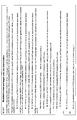
- FIG. 1 is a diagram for explaining four types of side link transmission modes in NR-V2X.
- the user device 20A has a PSCCH (Physical Sidelink Control Channel) / PSCH (Physical Sidelink Sharp Chain) with respect to the user device 20B based on the SL (Sidelink) scheduling by the base station device 10. ) Is sent.
- PSCCH Physical Sidelink Control Channel
- PSCH Physical Sidelink Sharp Chain
- PSCCH / PSCH transmission is performed based on the resource selection of the user device itself.
- the side link transmission mode 2 of the NR-V2X is further subdivided.
- the user device 20A is transferred to the user device 20B based on the resource selection of the user device 20A itself.
- the PSCCH / PSCH is transmitted to the user device A, and the user device 20B transmits the PSCCH / PSCH to the user device A based on the resource selection of the user device 20B itself.
- the user device 20A is sent to the user device 20B according to the RRC-config of the resource pattern (resource pattern) notified from the base station device 10 or determined by the specification.
- PSSCH is transmitted to the PSCH.
- the user apparatus 20A performs scheduling for transmission of the user apparatus 20B by transmitting SL scheduling to the user apparatus 20B, and the user apparatus 20B performs scheduling for transmission thereof. Based on the scheduling, PSCCH / PSSCH is transmitted to the user device 20A.
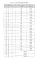
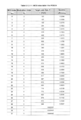
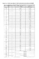
- MCS table 2A, 2B, 2C, 2D, 2E, 2F, 2G, and 2H are diagrams for explaining an MCS table used for transmitting PDSCH and PUSCH.
- the MCS table used for PDSCH and PUSCH transmission has a modulation method from QPSK (Quadrature phase shift keying) to 64QAM (Quadrature amplitude).
- a table including QPSK to 256QAM as a modulation method, and a table suitable for high-reliability and low-delay communication are included.
- the MCS table, MCS index (I MCS), modulation order (Q m), the target code rate (R), include spectral efficiency (Spectral efficiency).
- FIGS. 2A, 2B, 2C, 2D, 2E, 2F, 2G, and 2H it is defined in what case and which MCS table is used in PDSCH / PUSCH transmission. ing.
- One MCS table may be set (in advance) and used from all the MCS tables available for NR-Uu (ie, for PDSCH / PUSCH).
- the parameters of the upper layer may be assumed.
- the parameter may be defined as PSCH-Config.
- the PSCH-Config may include the parameter mcs-Table.
- the one MCS table may be set (in advance) for each of the following elements and used.
- SCI format b) DCI (Downlink Control Information) format
- c RNTI (Radio Network Temporary Identifier) scrambling the CRC of SCI and / or DCI.
- D Resource allocation mode
- mode 1 mode in which the base station gNB schedules SL resources.
- Mode 2 mode in which the user equipment UE autonomously selects SL resources
- the user apparatus 20 when the parameter mcs-Table of the upper layer included in the PSCH-Config is set to "aaa” and the PSCH is scheduled by the PSCCH having the SCI (Sidelink Control Information) format "X", the user apparatus 20 , using a MCS index (I MCS) and MCS table "Y", to determine the modulation order (Q m) and the target code rate (R) used for transmission of PSSCH.
- SCI Segment Control Information
- a plurality of MCS tables may be set (in advance) from all the MCS tables available for NR-Uu, and one of the set plurality of MCS tables may be selected or notified.
- the one MCS table may be selected or notified by the SCI format and / or the DCI (Downlink Control Information) format, and the CRC of the SCI and / or the DCI is scrambled by the RNTI (Radio Network Temporary Identifier). May be selected or notified by, or may be selected or notified by a dedicated SCI field and / or DCI field, resource allocation mode (mode 1: mode in which base station gNB schedules SL resources; mode 2: user equipment.
- mode 1 mode in which base station gNB schedules SL resources
- mode 2 user equipment.
- one MCS table is set (in advance) from all the MCS tables available for NR-Uu, and it is determined whether the one MCS table is used or another MCS table is used. May be done.
- whether the one MCS table is used or another MCS table is used may be determined by the SCI format and / or the DCI (Downlink Control Information) format, and the CRC of the SCI and / or the DCI. It may be determined by the RNTI (Radio Network Temperature Identifier) scrambled, or it may be determined by a dedicated SCI field and / or DCI field, and the resource allocation mode (mode 1: base station gNB schedules SL resources.
- Mode 2: Mode 2: Mode 2: Mode in which the user equipment UE autonomously selects the SL resource) may be determined by the option of the PSCCH / PSCH multiplexing method, and may be determined by the resource pool setting. May be good.
- the MCS table set for NR-Uu may be applied to the side link (SL) as it is.
- One MCS table may be set (in advance) and used from among all the MCS tables available for NR-Uu (that is, for PDSCH / PUSCH) except for a part.
- the parameters of the upper layer may be assumed.
- the parameter may be defined as PSCH-Config.
- the PSCH-Config may include the parameter mcs-Table.
- the one MCS table may be set (in advance) for each of the following elements and used.
- DCI Downlink Control Information
- c Radio Network Temporary Identifier
- D Resource allocation mode
- Mode 1 mode in which the base station gNB schedules SL resources.
- Mode 2 mode in which the user equipment UE autonomously selects SL resources.
- E PSCCH / PSSCH multiplexing method options
- f Resource pool settings
- the user apparatus 20 when the parameter mcs-Table of the upper layer included in the PSCH-Config is set to "aaa” and the PSCH is scheduled by the PSCCH having the SCI (Sidelink Control Information) format "X", the user apparatus 20 , using a MCS index (I MCS) and MCS table "Y", to determine the modulation order (Q m) and the target code rate (R) used for transmission of PSSCH.
- SCI Segment Control Information
- a plurality of MCS tables are set (in advance) from among all the MCS tables available for NR-Uu (that is, for PDSCH / PUSCH) except for a part, and a plurality of set MCS tables are set.
- One of the MCS tables may be selected or notified.
- the one MCS table may be selected or notified by the SCI format and / or the DCI (Downlink Control Information) format, and the CRC of the SCI and / or the DCI is scrambled by the RNTI (Radio Network Temporary Identifier).
- RNTI Radio Network Temporary Identifier
- resource allocation mode mode 1: mode in which base station gNB schedules SL resources; mode 2: user equipment. It may be selected or notified by the mode in which the UE autonomously selects the SL resource), it may be selected or notified by the option of the PSCCH / PSSCH multiplexing method, or it may be selected or notified by the setting of the resource pool. ..
- one MCS table is set (in advance) from all the MCS tables available for NR-Uu (that is, for PDSCH / PUSCH) except for a part, and the one MCS table is set. May be used, or it may be determined whether another MCS table is used.
- whether the one MCS table is used or another MCS table is used may be determined by the SCI format and / or the DCI (Downlink Control Information) format, and the CRC of the SCI and / or the DCI. It may be determined by the RNTI (Radio Network Temperature Identifier) scrambled, or it may be determined by a dedicated SCI field and / or DCI field, and the resource allocation mode (mode 1: base station gNB schedules SL resources.
- RNTI Radio Network Temperature Identifier
- Mode 2 The mode in which the user equipment UE autonomously selects the SL resource) may be determined, or may be determined by the option of the PSCCH / PSCH multiplexing method, and the selection or notification may be determined by the resource pool setting. May be done.
- the predetermined MCS table is included in the MCS table excluding a part from all the MCS tables available for NR-Uu (that is, for PDSCH / PUSCH)
- the predetermined MCS table is used as it is. It may be applied to the side link (SL).
- the given MCS table is not included in the MCS table except for some of all the MCS tables available for NR-Uu (ie PDSCH / PUSCH), then for NR-Uu (ie PDSCH).
- One specific MCS table included in the MCS table excluding a part from all the MCS tables available for / PUSCH may be applied to the side link (SL).
- MCS index I MCS
- MCS table Y
- the user device 20 was CRC scrambled by Z (eg SL-V-RNTI).
- Z eg SL-V-RNTI
- I MCS MCS index
- MCS table indicated by the PSCCH including SCI format "X”
- PSSCH by PSCCH having CRC scrambled SCI format "X” by Z (eg SL-VRNTI) scheduled by PDCCH having DCI format P CRC scrambled by Q (eg SL-V-RNTI) indicated with MCS index (I MCS) and MCS table "Y"
- I MCS MCS index
- R target code rate
- MCS table is applicable to PSCCH and / or PSCH and / or PSFCH (Physical Sidelink Feedback Channel) and / or other side link channels.
- the user device 20 can determine which MCS table is used.
- the MCS table can be switched based on the state of the channel and / or the judgment of the user apparatus.
- the amount of the mounting test of the user apparatus 20 can be reduced.
- the user device 20 since only one MCS table can be used, the user device 20 does not need to consider setting and switching, and the specifications of the user device 20 can be simplified.
- the base station apparatus 10 and the user apparatus 20 include a function of carrying out the above-described embodiment.
- the base station device 10 and the user device 20 may each have only a part of the functions in the embodiment.
- FIG. 3 is a diagram showing an example of the functional configuration of the base station device 10.
- the base station apparatus 10 includes a transmission unit 110, a reception unit 120, a setting unit 130, and a control unit 140.
- the functional configuration shown in FIG. 3 is only an example. Any function classification and name of the functional unit may be used as long as the operation according to the embodiment of the present invention can be performed.
- the transmission unit 110 includes a function of generating a signal to be transmitted to the user device 20 side and transmitting the signal wirelessly. In addition, the transmission unit 110 transmits information such as SL scheduling to the user device 20.
- the receiving unit 120 includes a function of receiving various signals transmitted from the user apparatus 20 and acquiring information of, for example, a higher layer from the received signals.
- the setting unit 130 stores preset setting information and various setting information to be transmitted to the user device 20 in the storage device, and reads them out from the storage device as needed.
- the content of the setting information is, for example, information related to the setting of V2X.
- control unit 140 performs processing related to the setting for the user device 20 to perform V2X. Further, the function unit related to signal transmission in the control unit 140 may be included in the transmission unit 110, and the function unit related to signal reception in the control unit 140 may be included in the reception unit 120.
- FIG. 4 is a diagram showing an example of the functional configuration of the user device 20.
- the user device 20 includes a transmission unit 210, a reception unit 220, a setting unit 230, and a control unit 240.
- the functional configuration shown in FIG. 4 is only an example. Any function classification and name of the functional unit may be used as long as the operation according to the embodiment of the present invention can be performed.
- the transmission unit 210 creates a transmission signal from the transmission data and wirelessly transmits the transmission signal.
- the receiving unit 220 wirelessly receives various signals and acquires a signal of a higher layer from the received signal of the physical layer. Further, the receiving unit 220 has a function of receiving the SL scheduling transmitted from the base station apparatus 10.
- the receiving unit 220 has a function of receiving a scheduling grant transmitted from another user device. For example, the transmission unit 210 transmits a scheduling request or the like to another user device 20 as V2X, and the reception unit 120 receives a scheduling grant or the like from the other user device 20.
- the setting unit 230 stores various setting information received from the base station device 10 or the user device 20 by the receiving unit 220 in the storage device, and reads it out from the storage device as needed.
- the setting unit 230 also stores preset setting information.
- the content of the setting information is, for example, information related to V2X and HARQ processing.
- the control unit 240 controls the D2D communication executed with the other user device 20 as described in the embodiment. Further, the control unit 240 executes V2X and HARQ processing.
- the function unit related to signal transmission in the control unit 240 may be included in the transmission unit 210, and the function unit related to signal reception in the control unit 240 may be included in the reception unit 220.
- each functional block may be realized by one device in which a plurality of elements are physically and / or logically combined, or two or more devices physically and / or logically separated from each other directly and. / Or indirectly (eg, wired and / or wireless) may be connected and realized by these plurality of devices.
- the word “device” can be read as a circuit, device, unit, etc.
- the hardware configuration of the base station device 10 and the user device 20 may be configured to include one or more of the devices shown by 1001 to 1006 shown in the figure, or may not include some of the devices. May be done.
- the processor 1001 For each function of the base station device 10 and the user device 20, by loading predetermined software (program) on the hardware such as the processor 1001 and the storage device 1002, the processor 1001 performs an calculation and the communication device 1004 communicates. It is realized by controlling the reading and / or writing of data in the storage device 1002 and the auxiliary storage device 1003.
- the processor 1001 reads a program (program code), a software module or data from the auxiliary storage device 1003 and / or the communication device 1004 into the storage device 1002, and executes various processes according to these.
- a program program code
- the program a program that causes a computer to execute at least a part of the operations described in the above-described embodiment is used.
- the transmission unit 110, the reception unit 120, the setting unit 130, and the control unit 140 of the base station device 10 shown in FIG. 3 may be stored in the storage device 1002 and realized by a control program that operates in the processor 1001.
- the storage device 1002 is a computer-readable recording medium, and is, for example, at least one of ROM (Read Only Memory), EPROM (Erasable Programmable ROM), EPROM (Electrically Erasable Programmable ROM), RAM (Random Access Memory), and the like. It may be configured.
- the storage device 1002 may be referred to as a register, a cache, a main memory (main storage device), or the like.
- the storage device 1002 can store a program (program code), a software module, or the like that can be executed to carry out the process according to the embodiment of the present invention.
- the auxiliary storage device 1003 is a computer-readable recording medium, and is, for example, an optical disk such as a CD-ROM (Compact Disc ROM), a hard disk drive, a flexible disk, an optical magnetic disk (for example, a compact disk, a digital versatile disk, Blu).
- -It may be composed of at least one of a ray (registered trademark) disk), a smart card, a flash memory (for example, a card, a stick, a key drive), a floppy (registered trademark) disk, a magnetic strip, and the like.
- the auxiliary storage device 1003 may be referred to as an auxiliary storage device.
- the storage medium described above may be, for example, a database, server or other suitable medium containing the storage device 1002 and / or the auxiliary storage device 1003.
- the communication device 1004 is hardware (transmission / reception device) for communicating between computers via a wired and / or wireless network, and is also referred to as, for example, a network device, a network controller, a network card, a communication module, or the like.
- the transmission unit 110 and the reception unit 120 of the base station device 10 may be realized by the communication device 1004.
- the transmission unit 210 and the reception unit 220 of the user device 20 may be realized by the communication device 1004.
- the input device 1005 is an input device (for example, a keyboard, a mouse, a microphone, a switch, a button, a sensor, etc.) that receives an input from the outside.
- the output device 1006 is an output device (for example, a display, a speaker, an LED lamp, etc.) that outputs to the outside.
- the input device 1005 and the output device 1006 may have an integrated configuration (for example, a touch panel).
- the base station device 10 and the user device 20 are a microprocessor, a digital signal processor (DSP: Digital Signal Processor), an ASIC (Application Specific Integrated Circuit), a PLD (Programmable Logic Device), an FPGA (Field Programmable Gate Array), etc., respectively. It may be configured to include the hardware of, and a part or all of each functional block may be realized by the hardware. For example, processor 1001 may be implemented on at least one of these hardware.
- the above configuration provides a technique for defining how to use the MCS table in direct communication between terminals.
- the boundary of the functional unit or the processing unit in the functional block diagram does not always correspond to the boundary of the physical component.
- the operation of the plurality of functional units may be physically performed by one component, or the operation of one functional unit may be physically performed by a plurality of components. With respect to the processing procedure described in the embodiment, the order of processing may be changed as long as there is no contradiction.
- the base station apparatus 10 and the user apparatus 20 have been described with reference to functional block diagrams, but such devices may be implemented in hardware, software, or a combination thereof.
- the software operated by the processor of the base station apparatus 10 according to the embodiment of the present invention and the software operated by the processor of the user apparatus 20 according to the embodiment of the present invention are random access memory (RAM), flash memory, and read, respectively. It may be stored in a dedicated memory (ROM), EPROM, EEPROM, registers, hard disk (HDD), removable disk, CD-ROM, database, server or any other suitable storage medium.
- information notification includes physical layer signaling (for example, DCI (Downlink Control Information), UCI (Uplink Control Information)), higher layer signaling (for example, RRC (Radio Resource Control) signaling, MAC (Medium Access Control) signaling, etc. Broadcast information (MIB (Master Information Block), SIB (System Information Block)), other signals or a combination thereof may be used.
- RRC signaling may be referred to as an RRC message, for example, RRC. It may be a connection setup (RRCConnectionSetup) message, an RRC connection reconfiguration (RRCConnectionReconfiguration) message, or the like.
- Each aspect / embodiment described in the present specification includes LTE (LongTermEvolution), LTE-A (LTE-Advanced), SUPER 3G, IMT-Advanced, 4G, 5G, FRA (FutureRadioAccess), W-CDMA. (Registered Trademarks), GSM (Registered Trademarks), CDMA2000, UMB (Ultra-Mobile Broadband), IEEE 802.11 (Wi-Fi), IEEE 802.16 (WiMAX), IEEE 802.20, UWB (Ultra-WideBand), It may be applied to systems utilizing Bluetooth®, other suitable systems and / or next-generation systems extended based on them.
- the specific operation performed by the base station apparatus 10 in the present specification may be performed by its upper node (upper node).
- various operations performed for communication with the user device 20 are other than the base station device 10 and / or the base station device 10. It is clear that it can be done by other network nodes, such as, but not limited to, MME or S-GW.
- MME Mobility Management Entity
- S-GW Serving Mobility Management Entity
- the user device 20 may be a subscriber station, a mobile unit, a subscriber unit, a wireless unit, a remote unit, a mobile device, a wireless device, a wireless communication device, a remote device, a mobile subscriber station, an access terminal, a mobile terminal, etc. It may also be referred to as a wireless terminal, remote terminal, handset, user agent, mobile client, client, or some other suitable term.
- the base station apparatus 10 may be referred to by those skilled in the art by NB (NodeB), eNB (evolvedNodeB), gNB, BaseStation, or some other suitable term.
- NB NodeB
- eNB evolvedNodeB
- gNB BaseStation
- judgment and “decision” mean that “resolving”, “selecting”, “choosing”, “establishing”, “comparing”, etc. are regarded as “judgment” and “decision”. Can include. That is, “judgment” and “decision” may include that some action is regarded as “judgment” and “decision”.
- the resource request is an example of a scheduling request
- the resource grant is an example of a scheduling grant
- the scheduling user device is an example of a header user device.
- Base station device 110 Transmission unit 120 Reception unit 130 Setting unit 140 Control unit 20 User device 210 Transmission unit 220 Reception unit 230 Setting unit 240 Control unit 1001 Processor 1002 Storage device 1003 Auxiliary storage device 1004 Communication device 1005 Input device 1006 Output device
Landscapes
- Engineering & Computer Science (AREA)
- Computer Networks & Wireless Communication (AREA)
- Signal Processing (AREA)
- Quality & Reliability (AREA)
- Mobile Radio Communication Systems (AREA)
Abstract
Description
NR-V2Xにおけるサイドリンク送信モードについて説明する。
図2A、図2B、図2C、図2D、図2E、図2F、図2G、図2Hは、PDSCHやPUSCHの送信に用いられるMCSテーブルを説明するための図である。
実施形態1として、NRのサイドリンク(SL)において、2以上のMCSテーブルを利用可能とすることが考えられる。
(a)SCIフォーマット
(b)DCI(Downlink Control Information)フォーマット
(c)SCIおよび/またはDCIのCRCをスクランブルしているRNTI(Radio Network Temporary Identifier)
(d)リソース割当てモード(モード1:基地局gNBがSLリソースをスケジュールするモード。モード2:ユーザ装置UEが自律的にSLリソースを選択するモード)
(e)PSCCH/PSSCHの多重方法のオプション
(f)リソースプールの設定
実施形態1の変形例として、NRのサイドリンク(SL)において、NR-Uu用のMCSテーブルの一部を除いたMCSテーブルのうち(例えば、256QAMを含むMCSテーブルを除いたMCSテーブルのうち)、2以上のMCSテーブルを利用可能とすることが考えられる。すなわち、ユーザ装置20は、その除かれたMCSテーブルがNR-SL用に使用されることを期待しない、または、その除かれたMCSテーブルがNR-SL用に(予め)設定される/規定されることを期待しない。
(a)SCIフォーマット
(b)DCI(Downlink Control Information)フォーマット
(c)SCIおよび/またはDCIのCRCをスクランブルしているRNTI(Radio Network Temporary Identifier)
(d)リソース割当てモード(モード1:基地局gNBがSLリソースをスケジュールするモード。モード2:ユーザ装置UEが自律的にSLリソースを選択するモード)
(e)PSCCH/PSSCHの多重方法のオプション
(f)リソースプールの設定
実施形態2として、NRのサイドリンク(SL)において、一つだけのMCSテーブルを利用可能とすることが考えられる。
以上述べた実施形態により、ユーザ装置20は、どのMCSテーブルが使用されるかを判断することができる。
次に、これまでに説明した処理及び動作を実行する基地局装置10及びユーザ装置20の機能構成例を説明する。基地局装置10及びユーザ装置20は上述した実施例を実施する機能を含む。ただし、基地局装置10及びユーザ装置20はそれぞれ、実施例の中の一部の機能のみを備えることとしてもよい。
図3は、基地局装置10の機能構成の一例を示す図である。図3に示されるように、基地局装置10は、送信部110と、受信部120と、設定部130と、制御部140とを有する。図3に示される機能構成は一例に過ぎない。本発明の実施の形態に係る動作を実行できるのであれば、機能区分及び機能部の名称はどのようなものでもよい。
図4は、ユーザ装置20の機能構成の一例を示す図である。図4に示されるように、ユーザ装置20は、送信部210と、受信部220と、設定部230と、制御部240とを有する。図4に示される機能構成は一例に過ぎない。本発明の実施の形態に係る動作を実行できるのであれば、機能区分及び機能部の名称はどのようなものでもよい。
上述の本発明の実施の形態の説明に用いた機能構成図(図3及び図4)は、機能単位のブロックを示している。これらの機能ブロック(構成部)は、ハードウェア及び/又はソフトウェアの任意の組み合わせによって実現される。また、各機能ブロックの実現手段は特に限定されない。すなわち、各機能ブロックは、物理的及び/又は論理的に複数要素が結合した1つの装置により実現されてもよいし、物理的及び/又は論理的に分離した2つ以上の装置を直接的及び/又は間接的に(例えば、有線及び/又は無線)で接続し、これら複数の装置により実現されてもよい。
以上、説明したように、本発明の実施の形態によれば、MCSテーブルを決定する制御部と、前記MCSテーブルに従ってサイドリンク送信を行う送信部と、を有するユーザ装置が提供される。
以上、本発明の実施の形態を説明してきたが、開示される発明はそのような実施形態に限定されず、当業者は様々な変形例、修正例、代替例、置換例等を理解するであろう。発明の理解を促すため具体的な数値例を用いて説明がなされたが、特に断りのない限り、それらの数値は単なる一例に過ぎず適切な如何なる値が使用されてもよい。上記の説明における項目の区分けは本発明に本質的ではなく、2以上の項目に記載された事項が必要に応じて組み合わせて使用されてよいし、ある項目に記載された事項が、別の項目に記載された事項に(矛盾しない限り)適用されてよい。機能ブロック図における機能部又は処理部の境界は必ずしも物理的な部品の境界に対応するとは限らない。複数の機能部の動作が物理的には1つの部品で行われてもよいし、あるいは1つの機能部の動作が物理的には複数の部品により行われてもよい。実施の形態で述べた処理手順については、矛盾の無い限り処理の順序を入れ替えてもよい。処理説明の便宜上、基地局装置10及びユーザ装置20は機能的なブロック図を用いて説明されたが、そのような装置はハードウェアで、ソフトウェアで又はそれらの組み合わせで実現されてもよい。本発明の実施の形態に従って基地局装置10が有するプロセッサにより動作するソフトウェア及び本発明の実施の形態に従ってユーザ装置20が有するプロセッサにより動作するソフトウェアはそれぞれ、ランダムアクセスメモリ(RAM)、フラッシュメモリ、読み取り専用メモリ(ROM)、EPROM、EEPROM、レジスタ、ハードディスク(HDD)、リムーバブルディスク、CD-ROM、データベース、サーバその他の適切な如何なる記憶媒体に保存されてもよい。
110 送信部
120 受信部
130 設定部
140 制御部
20 ユーザ装置
210 送信部
220 受信部
230 設定部
240 制御部
1001 プロセッサ
1002 記憶装置
1003 補助記憶装置
1004 通信装置
1005 入力装置
1006 出力装置
Claims (5)
- MCS(Modulation and coding scheme)テーブルを決定する制御部と、
前記MCSテーブルに従ってサイドリンク送信を行う送信部と、を有する
ユーザ装置。 - 前記MCSテーブルは、サイドリンク送信用に利用可能な2以上のMCSテーブルの中から決定される、請求項1に記載のユーザ装置。
- 前記MCSテーブルは、所定のMCSテーブルを除くサイドリンク送信用に利用可能な2以上のMCSテーブルの中から決定される、請求項1に記載のユーザ装置。
- 前記MCSテーブルは、サイドリンク送信用に利用可能な一つだけのMCSテーブルである、請求項1に記載のユーザ装置。
- MCSテーブルを決定するステップと、
前記MCSテーブルに従ってサイドリンク送信を行うステップと、を有する
ユーザ装置の通信方法。
Priority Applications (5)
| Application Number | Priority Date | Filing Date | Title |
|---|---|---|---|
| US17/598,721 US20220173828A1 (en) | 2019-04-02 | 2019-04-02 | User apparatus and communication method |
| CN201980094798.1A CN113632535A (zh) | 2019-04-02 | 2019-04-02 | 用户装置及通信方法 |
| PCT/JP2019/014709 WO2020202481A1 (ja) | 2019-04-02 | 2019-04-02 | ユーザ装置及び通信方法 |
| EP19922478.3A EP3952436A4 (en) | 2019-04-02 | 2019-04-02 | USER DEVICE AND COMMUNICATION METHOD |
| JP2021511841A JP7313432B2 (ja) | 2019-04-02 | 2019-04-02 | 端末、通信システム及び通信方法 |
Applications Claiming Priority (1)
| Application Number | Priority Date | Filing Date | Title |
|---|---|---|---|
| PCT/JP2019/014709 WO2020202481A1 (ja) | 2019-04-02 | 2019-04-02 | ユーザ装置及び通信方法 |
Publications (1)
| Publication Number | Publication Date |
|---|---|
| WO2020202481A1 true WO2020202481A1 (ja) | 2020-10-08 |
Family
ID=72667273
Family Applications (1)
| Application Number | Title | Priority Date | Filing Date |
|---|---|---|---|
| PCT/JP2019/014709 Ceased WO2020202481A1 (ja) | 2019-04-02 | 2019-04-02 | ユーザ装置及び通信方法 |
Country Status (5)
| Country | Link |
|---|---|
| US (1) | US20220173828A1 (ja) |
| EP (1) | EP3952436A4 (ja) |
| JP (1) | JP7313432B2 (ja) |
| CN (1) | CN113632535A (ja) |
| WO (1) | WO2020202481A1 (ja) |
Cited By (1)
| Publication number | Priority date | Publication date | Assignee | Title |
|---|---|---|---|---|
| US20230345305A1 (en) * | 2020-04-22 | 2023-10-26 | Ntt Docomo, Inc. | Terminal and communication method |
Families Citing this family (4)
| Publication number | Priority date | Publication date | Assignee | Title |
|---|---|---|---|---|
| AU2019468770B2 (en) * | 2019-09-30 | 2025-11-06 | Guangdong Oppo Mobile Telecommunications Corp., Ltd. | Method and apparatus for determining sidelink transmission resource |
| US11962405B2 (en) * | 2019-10-02 | 2024-04-16 | Qualcomm Incorporated | Modulation and coding scheme table selection for sidelink communications |
| EP4021131A4 (en) * | 2019-11-14 | 2023-09-06 | Hyundai Motor Company | Method and device for transmitting and receiving sidelink data in communication system |
| US11665689B2 (en) * | 2020-06-22 | 2023-05-30 | Qualcomm Incorporated | Signaling apparatus and methods for superposition transmission of sidelink and uplink messages in V2X communications |
Citations (1)
| Publication number | Priority date | Publication date | Assignee | Title |
|---|---|---|---|---|
| US20180324010A1 (en) * | 2017-05-04 | 2018-11-08 | Qualcomm Incorporated | Limits for modulation and coding scheme values |
Family Cites Families (10)
| Publication number | Priority date | Publication date | Assignee | Title |
|---|---|---|---|---|
| EP3962013B1 (en) * | 2017-03-24 | 2023-10-25 | Telefonaktiebolaget Lm Ericsson (Publ) | Terminal device and method for facilitating communication between terminal devices |
| JP2019004319A (ja) * | 2017-06-15 | 2019-01-10 | シャープ株式会社 | 基地局装置、端末装置およびその通信方法 |
| EP3711209A1 (en) * | 2017-11-15 | 2020-09-23 | IDAC Holdings, Inc. | Polar coding system |
| US11115098B2 (en) * | 2018-04-06 | 2021-09-07 | Apple Inc. | Configuration and design of CQI and MCS tables for 5G communications |
| KR102574099B1 (ko) * | 2018-07-24 | 2023-09-04 | 주식회사 아이티엘 | 차량 통신을 지원하는 무선통신 시스템에서 무선 통신을 수행하는 방법 및 그 장치 |
| US20200053835A1 (en) * | 2018-08-08 | 2020-02-13 | Idac Holdings, Inc. | Uu interface enhancement for nr v2x |
| EP3857768A1 (en) * | 2018-09-25 | 2021-08-04 | IDAC Holdings, Inc. | Methods, devices, and systems for supporting harq on v2x |
| WO2020148264A1 (en) * | 2019-01-18 | 2020-07-23 | Fraunhofer-Gesellschaft zur Förderung der angewandten Forschung e.V. | Nr v2x resource pool definitions within a band width part |
| WO2020159297A1 (ko) * | 2019-02-01 | 2020-08-06 | 엘지전자 주식회사 | 무선통신시스템에서 사이드 링크 단말이 신호를 전송하는 방법 및 장치 |
| EP3949641A4 (en) * | 2019-03-27 | 2022-11-16 | Telefonaktiebolaget LM Ericsson (publ) | METHOD, TERMINAL AND BASE STATION FOR RANDOM ACCESS METHOD |
-
2019
- 2019-04-02 JP JP2021511841A patent/JP7313432B2/ja active Active
- 2019-04-02 US US17/598,721 patent/US20220173828A1/en active Pending
- 2019-04-02 EP EP19922478.3A patent/EP3952436A4/en not_active Withdrawn
- 2019-04-02 WO PCT/JP2019/014709 patent/WO2020202481A1/ja not_active Ceased
- 2019-04-02 CN CN201980094798.1A patent/CN113632535A/zh not_active Withdrawn
Patent Citations (1)
| Publication number | Priority date | Publication date | Assignee | Title |
|---|---|---|---|---|
| US20180324010A1 (en) * | 2017-05-04 | 2018-11-08 | Qualcomm Incorporated | Limits for modulation and coding scheme values |
Non-Patent Citations (3)
| Title |
|---|
| 3GPP TS 36.213, June 2017 (2017-06-01) |
| 3GPP TS 38.214, December 2018 (2018-12-01) |
| See also references of EP3952436A4 |
Cited By (2)
| Publication number | Priority date | Publication date | Assignee | Title |
|---|---|---|---|---|
| US20230345305A1 (en) * | 2020-04-22 | 2023-10-26 | Ntt Docomo, Inc. | Terminal and communication method |
| US12167279B2 (en) * | 2020-04-22 | 2024-12-10 | Ntt Docomo, Inc. | Terminal and communication method |
Also Published As
| Publication number | Publication date |
|---|---|
| CN113632535A (zh) | 2021-11-09 |
| JP7313432B2 (ja) | 2023-07-24 |
| JPWO2020202481A1 (ja) | 2020-10-08 |
| EP3952436A4 (en) | 2022-11-16 |
| US20220173828A1 (en) | 2022-06-02 |
| EP3952436A1 (en) | 2022-02-09 |
Similar Documents
| Publication | Publication Date | Title |
|---|---|---|
| CN113196856B (zh) | 通信装置及通信方法 | |
| CN112314029B (zh) | 通信装置及基站 | |
| JP2022071153A (ja) | 端末、通信システム、及び送信方法 | |
| WO2020136853A1 (ja) | 通信装置及びチャネル状態情報測定方法 | |
| JP7066751B2 (ja) | 端末及び基地局 | |
| JP7313432B2 (ja) | 端末、通信システム及び通信方法 | |
| US11924831B2 (en) | User equipment (UE) for performing flexible scheduling for inter-terminal direct communication | |
| JPWO2020012540A1 (ja) | ユーザ装置及び基地局装置 | |
| CN112292893B (zh) | 通信装置 | |
| WO2020136851A1 (ja) | ユーザ装置 | |
| WO2021005696A1 (ja) | 端末及び通信方法 | |
| WO2020188667A1 (ja) | 通信装置及び通信方法 | |
| JPWO2020031332A1 (ja) | ユーザ装置、基地局装置、及び測定方法 | |
| WO2018030121A1 (ja) | ユーザ装置及び信号送信方法 | |
| WO2020166088A1 (ja) | ユーザ装置及び通信方法 | |
| JPWO2020031348A1 (ja) | ユーザ装置 | |
| WO2020230213A1 (ja) | ユーザ装置 | |
| JP7568368B2 (ja) | 端末、基地局、通信システム及び通信方法 | |
| CN119255375A (zh) | 通信装置及通信方法 | |
| WO2022097290A1 (ja) | 端末及び通信システム | |
| EP4057758B1 (en) | Terminal and communication method | |
| US20220124848A1 (en) | User equipment | |
| JP2024150573A (ja) | 端末及び通信方法 | |
| EP3923659A1 (en) | User device and communication method | |
| US20220159675A1 (en) | User equipment |
Legal Events
| Date | Code | Title | Description |
|---|---|---|---|
| 121 | Ep: the epo has been informed by wipo that ep was designated in this application |
Ref document number: 19922478 Country of ref document: EP Kind code of ref document: A1 |
|
| ENP | Entry into the national phase |
Ref document number: 2021511841 Country of ref document: JP Kind code of ref document: A |
|
| NENP | Non-entry into the national phase |
Ref country code: DE |
|
| ENP | Entry into the national phase |
Ref document number: 2019922478 Country of ref document: EP Effective date: 20211102 |
|
| WWG | Wipo information: grant in national office |
Ref document number: 202117046011 Country of ref document: IN |