WO2020202483A1 - ユーザ装置 - Google Patents
ユーザ装置 Download PDFInfo
- Publication number
- WO2020202483A1 WO2020202483A1 PCT/JP2019/014711 JP2019014711W WO2020202483A1 WO 2020202483 A1 WO2020202483 A1 WO 2020202483A1 JP 2019014711 W JP2019014711 W JP 2019014711W WO 2020202483 A1 WO2020202483 A1 WO 2020202483A1
- Authority
- WO
- WIPO (PCT)
- Prior art keywords
- resource pool
- user device
- unit
- communication
- control
- Prior art date
- Legal status (The legal status is an assumption and is not a legal conclusion. Google has not performed a legal analysis and makes no representation as to the accuracy of the status listed.)
- Ceased
Links
Images




Classifications
-
- H—ELECTRICITY
- H04—ELECTRIC COMMUNICATION TECHNIQUE
- H04W—WIRELESS COMMUNICATION NETWORKS
- H04W4/00—Services specially adapted for wireless communication networks; Facilities therefor
- H04W4/30—Services specially adapted for particular environments, situations or purposes
- H04W4/40—Services specially adapted for particular environments, situations or purposes for vehicles, e.g. vehicle-to-pedestrians [V2P]
-
- H—ELECTRICITY
- H04—ELECTRIC COMMUNICATION TECHNIQUE
- H04W—WIRELESS COMMUNICATION NETWORKS
- H04W72/00—Local resource management
- H04W72/02—Selection of wireless resources by user or terminal
-
- H—ELECTRICITY
- H04—ELECTRIC COMMUNICATION TECHNIQUE
- H04L—TRANSMISSION OF DIGITAL INFORMATION, e.g. TELEGRAPHIC COMMUNICATION
- H04L1/00—Arrangements for detecting or preventing errors in the information received
- H04L1/08—Arrangements for detecting or preventing errors in the information received by repeating transmission, e.g. Verdan system
-
- H—ELECTRICITY
- H04—ELECTRIC COMMUNICATION TECHNIQUE
- H04L—TRANSMISSION OF DIGITAL INFORMATION, e.g. TELEGRAPHIC COMMUNICATION
- H04L1/00—Arrangements for detecting or preventing errors in the information received
- H04L1/12—Arrangements for detecting or preventing errors in the information received by using return channel
- H04L1/16—Arrangements for detecting or preventing errors in the information received by using return channel in which the return channel carries supervisory signals, e.g. repetition request signals
- H04L1/18—Automatic repetition systems, e.g. Van Duuren systems
- H04L1/1829—Arrangements specially adapted for the receiver end
- H04L1/1854—Scheduling and prioritising arrangements
-
- H—ELECTRICITY
- H04—ELECTRIC COMMUNICATION TECHNIQUE
- H04L—TRANSMISSION OF DIGITAL INFORMATION, e.g. TELEGRAPHIC COMMUNICATION
- H04L1/00—Arrangements for detecting or preventing errors in the information received
- H04L1/12—Arrangements for detecting or preventing errors in the information received by using return channel
- H04L1/16—Arrangements for detecting or preventing errors in the information received by using return channel in which the return channel carries supervisory signals, e.g. repetition request signals
- H04L1/18—Automatic repetition systems, e.g. Van Duuren systems
- H04L1/1867—Arrangements specially adapted for the transmitter end
- H04L1/1893—Physical mapping arrangements
-
- H—ELECTRICITY
- H04—ELECTRIC COMMUNICATION TECHNIQUE
- H04L—TRANSMISSION OF DIGITAL INFORMATION, e.g. TELEGRAPHIC COMMUNICATION
- H04L1/00—Arrangements for detecting or preventing errors in the information received
- H04L1/12—Arrangements for detecting or preventing errors in the information received by using return channel
- H04L1/16—Arrangements for detecting or preventing errors in the information received by using return channel in which the return channel carries supervisory signals, e.g. repetition request signals
- H04L1/18—Automatic repetition systems, e.g. Van Duuren systems
- H04L1/1867—Arrangements specially adapted for the transmitter end
- H04L1/1896—ARQ related signaling
-
- H—ELECTRICITY
- H04—ELECTRIC COMMUNICATION TECHNIQUE
- H04W—WIRELESS COMMUNICATION NETWORKS
- H04W72/00—Local resource management
- H04W72/50—Allocation or scheduling criteria for wireless resources
- H04W72/52—Allocation or scheduling criteria for wireless resources based on load
-
- H—ELECTRICITY
- H04—ELECTRIC COMMUNICATION TECHNIQUE
- H04W—WIRELESS COMMUNICATION NETWORKS
- H04W72/00—Local resource management
- H04W72/50—Allocation or scheduling criteria for wireless resources
- H04W72/56—Allocation or scheduling criteria for wireless resources based on priority criteria
-
- H—ELECTRICITY
- H04—ELECTRIC COMMUNICATION TECHNIQUE
- H04L—TRANSMISSION OF DIGITAL INFORMATION, e.g. TELEGRAPHIC COMMUNICATION
- H04L1/00—Arrangements for detecting or preventing errors in the information received
- H04L2001/0092—Error control systems characterised by the topology of the transmission link
-
- H—ELECTRICITY
- H04—ELECTRIC COMMUNICATION TECHNIQUE
- H04W—WIRELESS COMMUNICATION NETWORKS
- H04W92/00—Interfaces specially adapted for wireless communication networks
- H04W92/16—Interfaces between hierarchically similar devices
- H04W92/18—Interfaces between hierarchically similar devices between terminal devices
Definitions
- the present invention relates to a user device in a wireless communication system.
- LTE Long Term Evolution
- LTE-A Long Term Evolution Advanced
- NR New Radio
- 5G New Radio
- user devices communicate directly with each other without going through a base station device.
- D2D (Device to Device) technology to be performed is being studied (for example, Non-Patent Document 1).
- D2D reduces the traffic between the user device and the base station device, and enables communication between the user devices even when the base station device becomes incommunicable due to a disaster or the like.
- D2D is referred to as "sidelink", but in the present specification, D2D, which is a more general term, is used. However, in the description of the embodiment described later, a side link is also used if necessary.
- D2D communication includes D2D discovery (also referred to as D2D discovery) for discovering other user devices that can communicate, and D2D communication (D2D direct communication, D2D communication, terminal) for direct communication between user devices. It is also roughly divided into (also called direct communication, etc.).
- D2D communication, D2D discovery, etc. are not particularly distinguished, they are simply referred to as D2D.
- a signal transmitted / received in D2D is called a D2D signal.
- Various use cases of services related to V2X (Vehicle to Everything) in NR are being studied (for example, Non-Patent Document 2).
- HARQ Hybrid automatic repeat request
- control related to HARQ or repeated transmission was not executed based on the degree of congestion or QoS (Quality of Service) parameters, performance may deteriorate depending on the communication status.
- the present invention has been made in view of the above points, and an object of the present invention is to appropriately control retransmission in direct communication between terminals.
- a receiving unit that receives the resource pool settings, a communication unit that receives the physical control channel and the physical shared channel in the resource pool, and the resource pool are associated with the resource pool based on the resource pool settings.
- the control unit that determines whether the response related to the determined retransmission control is valid or invalid, and the retransmission control for the received physical shared channel when the response related to the determined retransmission control is valid.
- a user device having a transmitter for transmitting such a response is provided.
- retransmission can be appropriately controlled in direct communication between terminals.
- V2X It is a figure for demonstrating V2X. It is a figure for demonstrating the example (1) of the transmission mode of V2X. It is a figure for demonstrating the example (2) of the transmission mode of V2X. It is a figure for demonstrating the example (3) of the transmission mode of V2X. It is a figure for demonstrating the example (4) of the transmission mode of V2X. It is a figure for demonstrating the example (1) of the communication type of V2X. It is a figure for demonstrating the example (2) of the communication type of V2X. It is a figure for demonstrating the example (3) of the communication type of V2X. It is a sequence diagram for demonstrating the example of HARQ response in V2X in embodiment of this invention.
- LTE Long Term Evolution
- NR NR
- LAN Local Area Network
- the duplex system may be a TDD (Time Division Duplex) system, an FDD (Frequency Division Duplex) system, or other system (for example, Flexible Duplex, etc.). Method may be used.
- TDD Time Division Duplex
- FDD Frequency Division Duplex
- Method may be used.
- “configuring" the radio parameter or the like may mean that a predetermined value is set in advance (Pre-configure), or the base station apparatus 10 Alternatively, the radio parameter notified from the user device 20 may be set.
- FIG. 1 is a diagram for explaining V2X.
- V2X Vehicle to Everything
- eV2X enhanced V2X
- FIG. 1 V2X is a part of ITS (Intelligent Transport Systems), V2V (Vehicle to Vehicle) which means a communication mode between vehicles, and a roadside installed between a vehicle and a roadside.
- ITS Intelligent Transport Systems
- V2V Vehicle to Vehicle
- V2I Vehicle to Infrastructure
- V2N Vehicle to Network
- V2P Vehicle to Pedestrian
- V2X using LTE or NR cellular communication and terminal-to-terminal communication is being studied.
- V2X using cellular communication is also referred to as cellular V2X.
- studies are underway to realize large capacity, low delay, high reliability, and QoS (Quality of Service) control.
- LTE or NR V2X it is expected that studies not limited to 3GPP specifications will be promoted in the future. For example, ensuring interoperability, reducing costs by implementing higher layers, using or switching between multiple RATs (Radio Access Technology), compliance with regulations in each country, data acquisition, distribution, database management, and LTE or NR V2X platform. It is expected that the usage method will be examined.
- RATs Radio Access Technology
- the communication device is mounted on the vehicle, but the embodiment of the present invention is not limited to the embodiment.
- the communication device may be a terminal held by a person, the communication device may be a device mounted on a drone or an aircraft, and the communication device may be a base station, an RSU, a relay station (relay node), or the like. It may be a user device or the like having a scheduling ability.
- SL may be distinguished based on any or combination of UL (Uplink) or DL (Downlink) and the following 1) -4). Further, SL may have another name. 1) Time domain resource allocation 2) Frequency domain resource allocation 3) Reference synchronization signal (including SLSS (Sidelink Synchronization Signal)) 4) Reference signal used for path loss measurement for transmission power control
- SL or UL OFDM Orthogonal Frequency Division Multiplexing
- CP-OFDM Cyclic-Prefix OFDM
- DFT-S-OFDM Discrete Fourier Transform-Spread-OFDM
- Transform Precoded OFDM Transferformed Any of the above OFDM may be applied.
- Mode 3 and Mode 4 are defined regarding the allocation of SL resources to the user device 20.
- transmission resources are dynamically allocated by DCI (Downlink Control Information) transmitted from the base station device 10 to the user device 20.
- DCI Downlink Control Information
- SPS SemiPersistent Scheduling
- Mode 4 the user device 20 autonomously selects a transmission resource from the resource pool.
- the slot in the embodiment of the present invention may be read as a symbol, a mini slot, a subframe, a wireless frame, and a TTI (Transmission Time Interval).
- the cell in the embodiment of the present invention may be read as a cell group, a carrier component, a BWP, a resource pool, a resource, a RAT (Radio Access Technology), a system (including a wireless LAN), or the like.
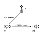
- FIG. 2 is a diagram for explaining an example (1) of the transmission mode of V2X.
- the base station apparatus 10 transmits the side link scheduling to the user apparatus 20A.
- the user device 20A transmits the PSCCH (Physical Sidelink Control Channel) and the PSCH (Physical Sidelink Shared Channel) to the user device 20B based on the received scheduling (step 2).
- the transmission mode of the side link communication shown in FIG. 2 may be referred to as the side link transmission mode 3 in LTE.
- side link transmission mode 3 in LTE Uu-based side link scheduling is performed.
- Uu is a wireless interface between UTRAN (Universal Terrestrial Radio Access Network) and UE (User Equipment).
- the side link communication transmission mode shown in FIG. 2 may be referred to as side link transmission mode 1 in NR.
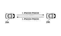
- FIG. 3 is a diagram for explaining an example (3) of the transmission mode of V2X.
- the user apparatus 20A transmits PSCCH and PSCH to the user apparatus 20B using autonomously selected resources.
- the user apparatus 20B transmits the PSCCH and the PSCH to the user apparatus 20A using the autonomously selected resource (step 1).
- the transmission mode of the side link communication shown in FIG. 3 may be referred to as the side link transmission mode 2a in NR.
- the UE In the side link transmission mode 2 in NR, the UE itself executes resource selection.
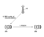
- FIG. 4 is a diagram for explaining an example (4) of the transmission mode of V2X.
- the base station apparatus 10 transmits the side link resource pattern to the user apparatus 20A via the RRC (Radio Resource Control) setting.
- the user apparatus 20A transmits the PSSCH to the user apparatus 20B based on the received resource pattern (step 1).
- the transmission mode of the side link communication shown in FIG. 4 may be referred to as the side link transmission mode 2c in NR.
- FIG. 5 is a diagram for explaining an example (5) of the transmission mode of V2X.
- the user apparatus 20C transmits the side link scheduling to the user apparatus 20A via the PSCCH.
- the user apparatus 20A transmits the PSCH to the user apparatus 20B based on the received scheduling (step 2).
- the transmission mode of the side link communication shown in FIG. 5 may be referred to as the side link transmission mode 2d in NR.
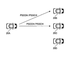
- FIG. 6 is a diagram for explaining an example (1) of the communication type of V2X.
- the sidelink communication type shown in FIG. 6 is unicast.
- the user device 20A transmits PSCCH and PSCH to the user device 20.
- the user device 20A unicasts the user device 20B and also unicasts the user device 20C.
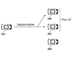
- FIG. 7 is a diagram for explaining an example (2) of the communication type of V2X.
- the sidelink communication type shown in FIG. 7 is group cast.
- the user device 20A transmits PSCCH and PSCH to the group to which one or more user devices 20 belong.
- the group includes the user device 20B and the user device 20C, and the user device 20A performs a group cast to the group.
- FIG. 8 is a diagram for explaining an example (3) of the communication type of V2X.
- the sidelink communication type shown in FIG. 8 is broadcast.
- the user device 20A transmits PSCCH and PSCH to one or more user devices 20.
- the user device 20A broadcasts to the user device 20B, the user device 20C, and the user device 20D.
- sidelink HARQ responses are supported in unicast and groupcast. Whether to enable or disable the HARQ response in the sidelink unicast and groupcast needs to be set.
- the HARQ response may be enabled at all times, or the HARQ response may actually be executed based on additional conditions.
- the HARQ response on the side link may be invalidated if necessary.
- Retransmission by HARQ can reduce system performance under conditions of high channel congestion.
- QoS Quality of Service
- PSFCH Physical Sidelink Feedback Channel
- enabling or disabling retransmission by the transmitting UE is more important than enabling or disabling the HARQ response.
- PSFCH may not be set. That is, from the viewpoint of efficient use of resources, more resources may be allocated to data transmission without setting PSFCH.
- HARQ responses may be invalidated in resource pools where PSFCH is not configured.
- the HARQ response may be enabled or disabled for each resource pool. Also, retransmission in the transmitting UE may be enabled or disabled based on QoS or congestion control.
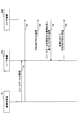
- FIG. 9 is a sequence diagram for explaining an example of the HARQ response in V2X according to the embodiment of the present invention. A method of enabling or disabling the HARQ response unique to the resource pool will be described with reference to FIG.
- the base station apparatus 10 transmits the resource pool settings to the user apparatus 20A and the user apparatus 20B.
- the resource pool settings may include settings related to HARQ responses.
- the setting related to the HARQ response may be, for example, 1-bit signaling indicating whether the HARQ response is valid or invalid in the resource pool.
- the setting related to the HARQ response may be implicitly notified by the setting of the resource pool.
- the HARQ response may be valid if there is a PSFCH resource setting associated with the resource pool, and the HRQ response may be invalid if there is no PSFCH resource setting associated with the resource pool.
- the HARQ response may be valid, and if the priority is equal to or less than the predetermined value in the resource pool, the HARQ response is invalid. There may be.
- the resource pool settings in steps S1 and S2 may be transmitted from the user device 20 instead of the base station device 10.
- step S3 the user device 20A transmits PSCCH and PSCH to the user device 20B in the resource pool based on the resource pool setting received in step S1, and the user device 20B receives the PSCCH and PSCH. Subsequently, in step S4, the user apparatus 20B executes PSFCH transmission based on the resource pool setting or the communication status.
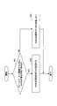
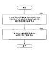
- FIG. 10 is a flowchart for explaining an example (1) of the HARQ response in V2X according to the embodiment of the present invention. Step S4 shown in FIG. 9 will be described in detail with reference to FIG.
- step S41 the user apparatus 20B determines whether or not the HARQ response associated with the resource pool including the received PSCH is valid. If the HARQ response is valid (YES in S41), the process proceeds to step S42, and if the HARQ response is invalid (NO in S41), the process proceeds to step S43.
- the determination in step S41 is executed based on the resource pool setting received in step S2 shown in FIG.
- step S42 the user apparatus 20B transmits a HARQ response to the user apparatus 20A by PSFCH.
- step S43 the user apparatus 20B does not transmit the HARQ response to the user apparatus 20A by PSFCH.
- the validity or invalidity of the HARQ response may be set or predetermined, notified, activated, or deactivated.
- the HARQ response is enabled by default, and the network may disable the HARQ response by RRC signaling, MAC-CE (Medium Access Control-Control Element) signaling, or DCI (Downlink Control Information) signaling.
- RRC Radio Resource Control
- MAC-CE Medium Access Control-Control Element
- DCI Downlink Control Information
- the user device 20 may be set to enable or disable the HARQ response, or may be notified, via RRC signaling via the side link, signaling by MAC-CE, or signaling by SCI (Sidelink Control Information). It may be activated or deactivated.
- the validity or invalidity of the HARQ response may be defined in the individual fields of signaling by DCI or SCI.
- the validity or invalidity of the HARQ response may be defined by a special combination of existing fields that is not directly related to the HARQ response of the signaling.
- the new DCI or SCI format may define the validity or invalidity of the HARQ response.
- the validity or invalidity of the HARQ response may be defined by RNTI (Radio Network Temporary Identifier), CORESET (Control resource set) or the search space.
- RNTI Radio Network Temporary Identifier
- CORESET Control resource set
- the HARQ response activation indicator included in the SCI may notify the validity or invalidity of the HARQ response.
- the indicator may be joint-encoded to the PSFCH resource settings or the PSCCH and HARQ response timing settings.
- the indicator may also be included in a DCI or SCI that schedules sidelink transmissions.
- step S5 the user apparatus 20A retransmits the PSCCH and the PSCH to the user apparatus 20B as needed.
- FIG. 11 is a flowchart for explaining an example (2) of the HARQ response in V2X according to the embodiment of the present invention. Step S5 shown in FIG. 9 will be described in detail with reference to FIG.
- step S51 the user apparatus 20A determines the maximum number of retransmissions per transport block based on the congestion degree of the resource pool or the QoS parameter.
- Table 1 is a table showing an example of mapping between the congestion degree or QoS parameter of the resource pool and the maximum number of retransmissions.
- the degree of congestion may be, for example, CBR (Channel Busy Ratio).
- the priority is associated with the 5G QoS characteristics, with lower values defining higher priorities.
- the reliability may be, for example, PER (Packet Error Rate).
- the PER indicates an upper limit of the ratio of the PDU such as the transmitted IP packet to the PDU that has not been successfully received.
- the maximum per transport block when the priority is "Priority # 0" or the reliability is "10 minus 6".
- the number of retransmissions is set to 5.
- the maximum number of retransmissions per transport block is set to 4.
- the maximum number of retransmissions per transport block is set to 3. ..
- the maximum number of retransmissions per transport block is set to 3. .
- the maximum number of retransmissions per transport block is set to 2. Will be done. As described above, the lower the priority or the lower the reliability, the smaller the maximum number of retransmissions may be set.
- step S52 the user device 20A retransmits as necessary up to the maximum number of retransmissions determined in step S51.
- the transmitting UE may notify the receiving UE of the maximum number of retransmissions via, for example, SCI.
- the maximum number of retransmissions may be the total number of transmissions including the number of repeated transmissions not based on the HARQ response and the number of retransmissions based on the HARQ response, and the maximum number of retransmissions is the number of repeated transmissions not based on the HARQ response.
- the number of retransmissions due to the HARQ response may be any number of times.
- the repetitive transmission that does not depend on the HARQ response may be called a blind retransmission or a repetition (s).
- the number of repeated transmissions not based on the HARQ response and the number of retransmissions based on the HARQ response may have different mappings with the degree of congestion, priority, or reliability.
- the number of repeated transmissions that does not depend on the HARQ response may be the number of repetition transmissions, or the number of transmissions on the PSCH in a plurality of slots scheduled via one DCI or SCI. May be good.
- the retransmission of the transport block may be executed when the actual number of transmissions including the retransmission is less than the maximum number of transmissions shown in Table 1. That is, when the actual number of transmissions is the same as the maximum number of transmissions shown in Table 1, the user apparatus 20A does not have to perform further retransmission. Further, when the retransmission based on the HARQ response is applied, the retransmission of the tramport block may be executed only when NACK or DTX of the HARQ response is detected.
- the maximum number of transmissions shown in Table 1 may be updated at any time based on the resource pool congestion or QoS parameters.
- the updated maximum number of transmissions may be notified to the receiving UE or another UE via SCI.
- the user apparatus 20 can determine whether or not to transmit the HARQ response based on the information indicating the validity or invalidity of the HARQ response associated with the resource pool.
- the user device 20 can determine the maximum number of transmissions of the transport block based on the congestion degree of the side link and the mapped priority or reliability.
- the base station apparatus 10 and the user apparatus 20 include a function of carrying out the above-described embodiment.
- the base station device 10 and the user device 20 may each have only a part of the functions in the embodiment.
- FIG. 12 is a diagram showing an example of the functional configuration of the base station device 10.
- the base station apparatus 10 includes a transmission unit 110, a reception unit 120, a setting unit 130, and a control unit 140.
- the functional configuration shown in FIG. 12 is only an example. Any function classification and name of the functional unit may be used as long as the operation according to the embodiment of the present invention can be performed.
- the transmission unit 110 includes a function of generating a signal to be transmitted to the user device 20 side and transmitting the signal wirelessly.
- the receiving unit 120 includes a function of receiving various signals transmitted from the user apparatus 20 and acquiring information of, for example, a higher layer from the received signals. Further, the transmission unit 110 has a function of transmitting NR-PSS, NR-SSS, NR-PBCH, DL / UL control signal, DL reference signal, etc. to the user device 20.
- the setting unit 130 stores preset setting information and various setting information to be transmitted to the user device 20 in the storage device, and reads them out from the storage device as needed.
- the content of the setting information is, for example, information related to the setting of D2D communication and retransmission control.
- control unit 140 performs processing related to the setting for the user device 20 to perform D2D communication. Further, the control unit 140 transmits the scheduling of the D2D communication to the user device 20 via the transmission unit 110. Further, the control unit 140 determines a parameter related to the retransmission control of the D2D communication and transmits the parameter to the user device 20 via the transmission unit 110.
- the function unit related to signal transmission in the control unit 140 may be included in the transmission unit 110, and the function unit related to signal reception in the control unit 140 may be included in the reception unit 120.
- FIG. 13 is a diagram showing an example of the functional configuration of the user device 20.
- the user device 20 includes a transmission unit 210, a reception unit 220, a setting unit 230, and a control unit 240.
- the functional configuration shown in FIG. 13 is only an example. Any function classification and name of the functional unit may be used as long as the operation according to the embodiment of the present invention can be performed.
- the transmission unit 210 creates a transmission signal from the transmission data and wirelessly transmits the transmission signal.
- the receiving unit 220 wirelessly receives various signals and acquires a signal of a higher layer from the received signal of the physical layer. Further, the receiving unit 220 has a function of receiving NR-PSS, NR-SSS, NR-PBCH, DL / UL / SL control signal, reference signal, etc. transmitted from the base station apparatus 10. Further, for example, the transmission unit 210 connects the other user device 20 to the PSCCH (Physical Sidelink Control Channel), PSCH (Physical Sidelink Shared Channel), PSDCH (Physical Sidelink Discovery Channel), PSBCH (Physical Sidelink Broadcast Channel) as D2D communication. ) Etc., and the receiving unit 220 receives the PSCCH, PSCH, PSDCH, PSBCH, etc. from the other user device 20.
- PSCCH Physical Sidelink Control Channel
- PSCH Physical Sidelink Shared Channel
- PSDCH Physical Sidelink Discovery Channel
- the setting unit 230 stores various setting information received from the base station device 10 or the user device 20 by the receiving unit 220 in the storage device, and reads it out from the storage device as needed.
- the setting unit 230 also stores preset setting information.
- the content of the setting information is, for example, information related to the setting of D2D communication and the setting of retransmission control.
- the control unit 240 controls D2D communication with another user device 20 as described in the embodiment. In addition, the control unit 240 performs processing related to HARQ of D2D communication. Further, the control unit 240 may transmit parameters related to scheduling and retransmission control of D2D communication to another user device 20.
- the function unit related to signal transmission in the control unit 240 may be included in the transmission unit 210, and the function unit related to signal reception in the control unit 240 may be included in the reception unit 220.
- each functional block may be realized by using one device that is physically or logically connected, or directly or indirectly (for example, by using two or more physically or logically separated devices). , Wired, wireless, etc.) and may be realized using these plurality of devices.
- the functional block may be realized by combining the software with the one device or the plurality of devices.
- Functions include judgment, decision, judgment, calculation, calculation, processing, derivation, investigation, search, confirmation, reception, transmission, output, access, solution, selection, selection, establishment, comparison, assumption, expectation, and assumption. Broadcasting, notifying, communicating, forwarding, configuring, reconfiguring, allocating, mapping, assigning, etc., but limited to these I can't.
- a functional block (constituent unit) that functions transmission is called a transmitting unit (transmitting unit) or a transmitter (transmitter).
- transmitting unit transmitting unit
- transmitter transmitter
- the base station device 10, the user device 20, and the like in one embodiment of the present disclosure may function as a computer that processes the wireless communication method of the present disclosure.
- FIG. 14 is a diagram showing an example of the hardware configuration of the base station device 10 and the user device 20 according to the embodiment of the present disclosure.
- the above-mentioned base station device 10 and user device 20 are physically configured as a computer device including a processor 1001, a storage device 1002, an auxiliary storage device 1003, a communication device 1004, an input device 1005, an output device 1006, a bus 1007, and the like. May be done.
- the word “device” can be read as a circuit, device, unit, etc.
- the hardware configuration of the base station device 10 and the user device 20 may be configured to include one or more of the devices shown in the figure, or may be configured not to include some of the devices.
- the processor 1001 For each function in the base station device 10 and the user device 20, by loading predetermined software (program) on the hardware such as the processor 1001 and the storage device 1002, the processor 1001 performs an calculation and the communication device 1004 performs communication. It is realized by controlling or controlling at least one of reading and writing of data in the storage device 1002 and the auxiliary storage device 1003.
- Processor 1001 operates, for example, an operating system to control the entire computer.
- the processor 1001 may be composed of a central processing unit (CPU: Central Processing Unit) including an interface with a peripheral device, a control device, an arithmetic unit, a register, and the like.
- CPU Central Processing Unit
- control unit 140, control unit 240, and the like may be realized by the processor 1001.
- the processor 1001 reads a program (program code), a software module, data, or the like from at least one of the auxiliary storage device 1003 and the communication device 1004 into the storage device 1002, and executes various processes according to these.
- a program that causes a computer to execute at least a part of the operations described in the above-described embodiment is used.
- the control unit 140 of the base station device 10 shown in FIG. 12 may be realized by a control program stored in the storage device 1002 and operated by the processor 1001.
- the control unit 240 of the user device 20 shown in FIG. 13 may be realized by a control program stored in the storage device 1002 and operated by the processor 1001.
- Processor 1001 may be implemented by one or more chips.
- the program may be transmitted from the network via a telecommunication line.
- the storage device 1002 is a computer-readable recording medium, for example, by at least one of ROM (Read Only Memory), EPROM (Erasable Programmable ROM), EPROM (Electrically Erasable Programmable ROM), RAM (Random Access Memory), and the like. It may be configured.
- the storage device 1002 may be referred to as a register, a cache, a main memory (main storage device), or the like.
- the storage device 1002 can store a program (program code), a software module, or the like that can be executed to implement the communication method according to the embodiment of the present disclosure.
- the auxiliary storage device 1003 is a computer-readable recording medium, and is, for example, an optical disk such as a CD-ROM (Compact Disc ROM), a hard disk drive, a flexible disk, an optical magnetic disk (for example, a compact disk, a digital versatile disk, Blu).
- -It may be composed of at least one of a ray (registered trademark) disk), a smart card, a flash memory (for example, a card, a stick, a key drive), a floppy (registered trademark) disk, a magnetic strip and the like.
- the storage medium described above may be, for example, a database, server or other suitable medium containing at least one of the storage device 1002 and the auxiliary storage device 1003.
- the communication device 1004 is hardware (transmission / reception device) for communicating between computers via at least one of a wired network and a wireless network, and is also referred to as, for example, a network device, a network controller, a network card, a communication module, or the like.
- the communication device 1004 includes, for example, a high frequency switch, a duplexer, a filter, a frequency synthesizer, and the like in order to realize at least one of frequency division duplex (FDD: Frequency Division Duplex) and time division duplex (TDD: Time Division Duplex). It may be composed of.
- FDD Frequency Division Duplex
- TDD Time Division Duplex
- the transmission / reception unit may be physically or logically separated from each other in the transmission unit and the reception unit.
- the input device 1005 is an input device (for example, a keyboard, a mouse, a microphone, a switch, a button, a sensor, etc.) that receives an input from the outside.
- the output device 1006 is an output device (for example, a display, a speaker, an LED lamp, etc.) that outputs to the outside.
- the input device 1005 and the output device 1006 may have an integrated configuration (for example, a touch panel).
- each device such as the processor 1001 and the storage device 1002 is connected by a bus 1007 for communicating information.
- the bus 1007 may be configured by using a single bus, or may be configured by using a different bus for each device.
- the base station device 10 and the user device 20 include a microprocessor, a digital signal processor (DSP: Digital Signal Processor), an ASIC (Application Specific Integrated Circuit), a PLD (Programmable Logic Device), an FPGA (Field Programmable Gate Array), and the like. It may be configured to include hardware, and the hardware may realize a part or all of each functional block. For example, processor 1001 may be implemented using at least one of these hardware.
- DSP Digital Signal Processor
- ASIC Application Specific Integrated Circuit
- PLD Programmable Logic Device
- FPGA Field Programmable Gate Array
- the receiving unit that receives the setting of the resource pool, the communication unit that receives the physical control channel and the physical shared channel in the resource pool, and the resource pool. Based on the settings, the control unit that determines whether the response related to the retransmission control associated with the resource pool is valid or invalid, and when the response related to the determined retransmission control is valid, the above.
- a user apparatus having a transmitter for transmitting a response related to retransmission control for a received physical shared channel is provided.
- the user apparatus 20 can determine whether or not to transmit the HARQ response based on the information indicating the validity or invalidity of the HARQ response associated with the resource pool. That is, in the direct communication between terminals, the response related to the retransmission control can be appropriately transmitted.
- the control unit determines whether the response related to the retransmission control associated with the resource pool is valid or invalid based on the 1-bit signaling including the valid or invalid signal included in the resource pool setting. You may. With this configuration, the user apparatus 20 can decide whether or not to transmit the HARQ response based on the information indicating the validity or invalidity of the HARQ response associated with the resource pool.
- the control unit responds to the retransmission control associated with the resource pool based on whether or not the resource pool is associated with a channel used to send and receive the response related to the retransmission control. May be determined whether is valid or invalid.
- the user apparatus 20 can decide whether or not to transmit the HARQ response based on the information indicating the validity or invalidity of the HARQ response associated with the resource pool.
- the control unit is effective in responding to the retransmission control associated with the resource pool based on whether or not the priority set in the resource pool exceeds a predetermined priority. You may decide whether it is present or invalid. With this configuration, the user apparatus 20 can decide whether or not to transmit the HARQ response based on the information indicating the validity or invalidity of the HARQ response associated with the resource pool.
- the receiving unit that receives the setting of the resource pool, the communication unit that transmits the physical control channel and the physical shared channel in the resource pool, and the setting of the resource pool.
- a user device having a control unit that determines the maximum number of retransmissions in the retransmission control associated with the resource pool and a transmission unit that executes retransmission control of the transmitted physical shared channel based on the determined maximum number of retransmissions. Provided.
- the user device 20 can determine the maximum number of transmissions of the transport block based on the congestion degree of the side link and the mapped priority or reliability. That is, in the direct communication between terminals, the response related to the retransmission control can be appropriately transmitted.
- the control unit may determine the maximum number of retransmissions based on the priority or reliability set in the resource pool and the congestion degree of the resource pool.
- the user apparatus 20 can determine the maximum number of transmissions of the transport block based on the congestion degree of the side link and the mapped priority or reliability.
- the boundary of the functional unit or the processing unit in the functional block diagram does not always correspond to the boundary of the physical component.
- the operation of the plurality of functional units may be physically performed by one component, or the operation of one functional unit may be physically performed by a plurality of components. With respect to the processing procedure described in the embodiment, the order of processing may be changed as long as there is no contradiction.
- the base station apparatus 10 and the user apparatus 20 have been described with reference to functional block diagrams, but such devices may be implemented in hardware, software, or a combination thereof.
- the software operated by the processor of the base station apparatus 10 according to the embodiment of the present invention and the software operated by the processor of the user apparatus 20 according to the embodiment of the present invention are random access memory (RAM), flash memory, and read, respectively. It may be stored in a dedicated memory (ROM), EPROM, EEPROM, registers, hard disk (HDD), removable disk, CD-ROM, database, server or any other suitable storage medium.
- information notification includes physical layer signaling (for example, DCI (Downlink Control Information), UCI (Uplink Control Information)), higher layer signaling (for example, RRC (Radio Resource Control) signaling, MAC (Medium Access Control) signaling, etc. Broadcast information (MIB (Master Information Block), SIB (System Information Block)), other signals, or a combination thereof may be used.
- RRC signaling may be referred to as an RRC message, for example, RRC. It may be a connection setup (RRCConnectionSetup) message, an RRC connection reconfiguration (RRCConnectionReconfiguration) message, or the like.
- Each aspect / embodiment described in the present disclosure includes LTE (Long Term Evolution), LTE-A (LTE-Advanced), SUPER 3G, IMT-Advanced, 4G (4th generation mobile communication system), and 5G (5th generation mobile communication).
- system FRA (Future Radio Access), NR (new Radio), W-CDMA (registered trademark), GSM (registered trademark), CDMA2000, UMB (Ultra Mobile Broadband), IEEE 802.11 (Wi-Fi (registered trademark)) )), IEEE 802.16 (WiMAX®), IEEE 802.20, UWB (Ultra-WideBand), Bluetooth®, and other systems that utilize suitable systems and have been extended based on these. It may be applied to at least one of the next generation systems. Further, a plurality of systems may be applied in combination (for example, a combination of at least one of LTE and LTE-A and 5G).
- the specific operation performed by the base station apparatus 10 in the present specification may be performed by its upper node (upper node).
- various operations performed for communication with the user device 20 are other than the base station device 10 and the base station device 10. It is clear that this can be done by at least one of the network nodes (eg, MME or S-GW, etc., but not limited to these).
- the network nodes eg, MME or S-GW, etc., but not limited to these.
- the other network nodes may be a combination of a plurality of other network nodes (for example, MME and S-GW). Good.
- the information, signals, etc. described in the present disclosure can be output from the upper layer (or lower layer) to the lower layer (or upper layer). Input / output may be performed via a plurality of network nodes.
- the input / output information and the like may be saved in a specific location (for example, memory), or may be managed using a management table. Input / output information and the like can be overwritten, updated, or added. The output information and the like may be deleted. The input information or the like may be transmitted to another device.
- the determination in the present disclosure may be made by a value represented by 1 bit (0 or 1), by a boolean value (Boolean: true or false), or by comparing numerical values (for example). , Comparison with a predetermined value).
- Software is an instruction, instruction set, code, code segment, program code, program, subprogram, software module, whether called software, firmware, middleware, microcode, hardware description language, or another name.
- Applications, software applications, software packages, routines, subroutines, objects, executable files, execution threads, procedures, functions, etc. should be broadly interpreted to mean.
- software, instructions, information, etc. may be transmitted and received via a transmission medium.
- a transmission medium For example, a website that uses at least one of wired technology (coaxial cable, fiber optic cable, twisted pair, digital subscriber line (DSL: Digital Subscriber Line), etc.) and wireless technology (infrared, microwave, etc.) When transmitted from a server, or other remote source, at least one of these wired and wireless technologies is included within the definition of transmission medium.
- data, instructions, commands, information, signals, bits, symbols, chips, etc. may be voltage, current, electromagnetic waves, magnetic fields or magnetic particles, light fields or photons, or any of these. It may be represented by a combination of.
- a channel and a symbol may be a signal (signaling).
- the signal may be a message.
- the component carrier CC: Component Carrier
- CC Component Carrier
- system and “network” used in this disclosure are used interchangeably.
- the information, parameters, etc. described in the present disclosure may be expressed using absolute values, relative values from predetermined values, or using other corresponding information. It may be represented.
- the radio resource may be one indicated by an index.
- base station Base Station
- wireless base station base station
- base station device fixed station
- NodeB nodeB
- eNodeB eNodeB
- GNB nodeB
- access point “ transmission point ”,“ reception point ”,“ transmission / reception point (transmission / reception point) ”,“ cell ”,“ sector ”
- Terms such as “cell group,” “carrier,” and “component carrier” can be used interchangeably.
- Base stations are sometimes referred to by terms such as macrocells, small cells, femtocells, and picocells.
- the base station can accommodate one or more (for example, three) cells.
- a base station accommodates multiple cells, the entire coverage area of the base station can be divided into multiple smaller areas, each smaller area being a base station subsystem (eg, a small indoor base station (RRH:)).
- Communication services can also be provided by Remote Radio Head).
- the term "cell” or “sector” refers to part or all of the coverage area of at least one of the base stations and base station subsystems that provide communication services in this coverage. Point to.
- MS Mobile Station
- UE User Equipment
- Mobile stations can be subscriber stations, mobile units, subscriber units, wireless units, remote units, mobile devices, wireless devices, wireless communication devices, remote devices, mobile subscriber stations, access terminals, mobile terminals, wireless, depending on the trader. It may also be referred to as a terminal, remote terminal, handset, user agent, mobile client, client, or some other suitable term.
- At least one of the base station and the mobile station may be called a transmitting device, a receiving device, a communication device, or the like.
- At least one of the base station and the mobile station may be a device mounted on the mobile body, the mobile body itself, or the like.
- the moving body may be a vehicle (eg, car, airplane, etc.), an unmanned moving body (eg, drone, self-driving car, etc.), or a robot (manned or unmanned). ) May be.
- at least one of the base station and the mobile station includes a device that does not necessarily move during communication operation.
- at least one of the base station and the mobile station may be an IoT (Internet of Things) device such as a sensor.
- IoT Internet of Things
- the base station in the present disclosure may be read by the user terminal.
- the communication between the base station and the user terminal is replaced with the communication between a plurality of user devices 20 (for example, it may be called D2D (Device-to-Device), V2X (Vehicle-to-Everything), etc.).
- D2D Device-to-Device
- V2X Vehicle-to-Everything
- Each aspect / embodiment of the present disclosure may be applied to the configuration.
- the user device 20 may have the functions of the base station device 10 described above.
- words such as "up” and “down” may be read as words corresponding to communication between terminals (for example, "side”).
- the uplink, downlink, and the like may be read as side channels.
- the user terminal in the present disclosure may be read as a base station.
- the base station may have the functions of the above-mentioned user terminal.
- determining and “determining” used in this disclosure may include a wide variety of actions.
- “Judgment” and “decision” are, for example, judgment (judging), calculation (calculating), calculation (computing), processing (processing), derivation (deriving), investigation (investigating), search (looking up, search, inquiry). It may include (eg, searching in a table, database or another data structure), ascertaining as “judgment” or “decision”.
- judgment and “decision” are receiving (for example, receiving information), transmitting (for example, transmitting information), input (input), output (output), and access. (Accessing) (for example, accessing data in memory) may be regarded as “judgment” or “decision”.
- judgment and “decision” mean that “resolving”, “selecting”, “choosing”, “establishing”, “comparing”, etc. are regarded as “judgment” and “decision”. Can include. That is, “judgment” and “decision” may include that some action is regarded as “judgment” and “decision”. Further, “judgment (decision)” may be read as “assuming”, “expecting”, “considering” and the like.
- connection means any direct or indirect connection or connection between two or more elements, and each other. It can include the presence of one or more intermediate elements between two “connected” or “combined” elements.
- the connection or connection between the elements may be physical, logical, or a combination thereof.
- connection may be read as "access”.
- the two elements use at least one of one or more wires, cables and printed electrical connections, and, as some non-limiting and non-comprehensive examples, the radio frequency domain. Can be considered to be “connected” or “coupled” to each other using electromagnetic energies having wavelengths in the microwave and light (both visible and invisible) regions.
- the reference signal can also be abbreviated as RS (Reference Signal), and may be called a pilot (Pilot) depending on the applicable standard.
- RS Reference Signal
- Pilot Pilot
- references to elements using designations such as “first”, “second”, etc. as used in this disclosure does not generally limit the quantity or order of those elements. These designations can be used in the present disclosure as a convenient way to distinguish between two or more elements. Thus, references to the first and second elements do not mean that only two elements can be adopted, or that the first element must somehow precede the second element.
- the wireless frame may be composed of one or more frames in the time domain. Each one or more frames in the time domain may be referred to as a subframe. Subframes may further consist of one or more slots in the time domain.
- the subframe may have a fixed time length (eg, 1 ms) that is independent of numerology.
- the numerology may be a communication parameter that applies to at least one of the transmission and reception of a signal or channel.
- Numerology includes, for example, subcarrier spacing (SCS: SubCarrier Spacing), bandwidth, symbol length, cyclic prefix length, transmission time interval (TTI: Transmission Time Interval), number of symbols per TTI, wireless frame configuration, transmitter / receiver.
- SCS subcarrier spacing
- TTI Transmission Time Interval
- At least one of a specific filtering process performed in the frequency domain, a specific windowing process performed by the transmitter / receiver in the time domain, and the like may be indicated.
- the slot may be composed of one or more symbols (OFDM (Orthogonal Frequency Division Multiplexing) symbol, SC-FDMA (Single Carrier Frequency Division Multiple Access) symbol, etc.) in the time domain. Slots may be time units based on new melody.
- OFDM Orthogonal Frequency Division Multiplexing
- SC-FDMA Single Carrier Frequency Division Multiple Access
- the slot may include a plurality of mini slots. Each minislot may consist of one or more symbols in the time domain. Further, the mini slot may be called a sub slot. A minislot may consist of a smaller number of symbols than the slot.
- a PDSCH (or PUSCH) transmitted in a time unit larger than the minislot may be referred to as a PDSCH (or PUSCH) mapping type A.
- the PDSCH (or PUSCH) transmitted using the minislot may be referred to as PDSCH (or PUSCH) mapping type B.
- the wireless frame, subframe, slot, minislot and symbol all represent the time unit when transmitting a signal.
- the radio frame, subframe, slot, minislot and symbol may have different names corresponding to each.
- one subframe may be called a transmission time interval (TTI), a plurality of consecutive subframes may be called TTI, and one slot or one minislot may be called TTI.
- TTI transmission time interval
- the unit representing TTI may be called a slot, a mini slot, or the like instead of a subframe.
- TTI refers to, for example, the minimum time unit of scheduling in wireless communication.
- the base station schedules each user device 20 to allocate radio resources (frequency bandwidth that can be used in each user device 20, transmission power, etc.) in TTI units.
- the definition of TTI is not limited to this.
- the TTI may be a transmission time unit such as a channel-encoded data packet (transport block), a code block, or a code word, or may be a processing unit such as scheduling or link adaptation.
- the time interval for example, the number of symbols
- the transport block, code block, code word, etc. may be shorter than the TTI.
- one or more TTIs may be the minimum time unit for scheduling. Further, the number of slots (number of mini-slots) constituting the minimum time unit of the scheduling may be controlled.
- a TTI having a time length of 1 ms may be referred to as a normal TTI (TTI in LTE Rel. 8-12), a normal TTI, a long TTI, a normal subframe, a normal subframe, a long subframe, a slot, or the like.
- TTIs shorter than normal TTIs may be referred to as shortened TTIs, short TTIs, partial TTIs (partial or fractional TTIs), shortened subframes, short subframes, minislots, subslots, slots, and the like.
- the long TTI (for example, normal TTI, subframe, etc.) may be read as a TTI having a time length of more than 1 ms, and the short TTI (for example, shortened TTI, etc.) is less than the TTI length of the long TTI and 1 ms. It may be read as a TTI having the above TTI length.
- the resource block (RB) is a resource allocation unit in the time domain and the frequency domain, and may include one or a plurality of continuous subcarriers in the frequency domain.
- the number of subcarriers contained in the RB may be the same regardless of the numerology, and may be, for example, 12.
- the number of subcarriers contained in the RB may be determined based on numerology.
- the time domain of RB may include one or more symbols, and may have a length of 1 slot, 1 mini slot, 1 subframe, or 1 TTI.
- Each 1TTI, 1 subframe, etc. may be composed of one or a plurality of resource blocks.
- one or more RBs include a physical resource block (PRB: Physical RB), a sub-carrier group (SCG: Sub-Carrier Group), a resource element group (REG: Resource Element Group), a PRB pair, an RB pair, and the like. May be called.
- PRB Physical resource block
- SCG Sub-Carrier Group
- REG Resource Element Group
- PRB pair an RB pair, and the like. May be called.
- the resource block may be composed of one or a plurality of resource elements (RE: Resource Element).
- RE Resource Element
- 1RE may be a radio resource area of 1 subcarrier and 1 symbol.
- Bandwidth part (which may also be called partial bandwidth) may represent a subset of consecutive common resource blocks (RBs) for a certain neurology in a carrier.
- the common RB may be specified by an index of the RB with respect to the common reference point of the carrier.
- PRBs may be defined in a BWP and numbered within that BWP.
- the BWP may include a BWP for UL (UL BWP) and a BWP for DL (DL BWP).
- UL BWP UL BWP
- DL BWP DL BWP
- One or more BWPs may be set in one carrier for the UE.
- At least one of the configured BWPs may be active, and the UE may not expect to send or receive a given signal / channel outside the active BWP.
- “cell”, “carrier” and the like in this disclosure may be read as “BWP”.
- the above-mentioned structures such as wireless frames, subframes, slots, mini slots and symbols are merely examples.
- the number of subframes contained in a wireless frame the number of slots per subframe or wireless frame, the number of minislots contained within a slot, the number of symbols and RBs contained in a slot or minislot, included in the RB.
- the number of subcarriers, the number of symbols in the TTI, the symbol length, the cyclic prefix (CP: Cyclic Prefix) length, and other configurations can be changed in various ways.
- the term "A and B are different” may mean “A and B are different from each other”.
- the term may mean that "A and B are different from C”.
- Terms such as “separate” and “combined” may be interpreted in the same way as “different”.
- the notification of predetermined information (for example, the notification of "being X") is not limited to the explicit notification, but is performed implicitly (for example, the notification of the predetermined information is not performed). May be good.
- the HARQ response is an example of a response related to retransmission control.
- PSSCH is an example of a physically shared channel.
- PSFCH is an example of a channel used for transmitting and receiving a response related to retransmission control.
- PSCCH is an example of a physical control channel.
- the transmitting unit 210 or the receiving unit 220 is an example of a communication unit.
- Base station device 110 Transmission unit 120 Reception unit 130 Setting unit 140 Control unit 20 User device 210 Transmission unit 220 Reception unit 230 Setting unit 240 Control unit 1001 Processor 1002 Storage device 1003 Auxiliary storage device 1004 Communication device 1005 Input device 1006 Output device
Landscapes
- Engineering & Computer Science (AREA)
- Computer Networks & Wireless Communication (AREA)
- Signal Processing (AREA)
- Mobile Radio Communication Systems (AREA)
- Communication Control (AREA)
Abstract
Description
1)時間領域のリソース配置
2)周波数領域のリソース配置
3)参照する同期信号(SLSS(Sidelink Synchronization Signal)を含む)
4)送信電力制御のためのパスロス測定に用いる参照信号

次に、これまでに説明した処理及び動作を実行する基地局装置10及びユーザ装置20の機能構成例を説明する。基地局装置10及びユーザ装置20は上述した実施例を実施する機能を含む。ただし、基地局装置10及びユーザ装置20はそれぞれ、実施例の中の一部の機能のみを備えることとしてもよい。
図12は、基地局装置10の機能構成の一例を示す図である。図12に示されるように、基地局装置10は、送信部110と、受信部120と、設定部130と、制御部140とを有する。図12に示される機能構成は一例に過ぎない。本発明の実施の形態に係る動作を実行できるのであれば、機能区分及び機能部の名称はどのようなものでもよい。
図13は、ユーザ装置20の機能構成の一例を示す図である。図13に示されるように、ユーザ装置20は、送信部210と、受信部220と、設定部230と、制御部240とを有する。図13に示される機能構成は一例に過ぎない。本発明の実施の形態に係る動作を実行できるのであれば、機能区分及び機能部の名称はどのようなものでもよい。
上記実施形態の説明に用いたブロック図(図12及び図13)は、機能単位のブロックを示している。これらの機能ブロック(構成部)は、ハードウェア及びソフトウェアの少なくとも一方の任意の組み合わせによって実現される。また、各機能ブロックの実現方法は特に限定されない。すなわち、各機能ブロックは、物理的又は論理的に結合した1つの装置を用いて実現されてもよいし、物理的又は論理的に分離した2つ以上の装置を直接的又は間接的に(例えば、有線、無線などを用いて)接続し、これら複数の装置を用いて実現されてもよい。機能ブロックは、上記1つの装置又は上記複数の装置にソフトウェアを組み合わせて実現されてもよい。
以上、説明したように、本発明の実施の形態によれば、リソースプールの設定を受信する受信部と、前記リソースプールにおいて物理制御チャネル及び物理共有チャネルを受信する通信部と、前記リソースプールの設定に基づいて、前記リソースプールに関連付けられた再送制御に係る応答が有効であるか又は無効であるかを決定する制御部と、前記決定された再送制御に係る応答が有効である場合、前記受信された物理共有チャネルに対する再送制御に係る応答を送信する送信部を有するユーザ装置が提供される。
以上、本発明の実施の形態を説明してきたが、開示される発明はそのような実施形態に限定されず、当業者は様々な変形例、修正例、代替例、置換例等を理解するであろう。発明の理解を促すため具体的な数値例を用いて説明がなされたが、特に断りのない限り、それらの数値は単なる一例に過ぎず適切な如何なる値が使用されてもよい。上記の説明における項目の区分けは本発明に本質的ではなく、2以上の項目に記載された事項が必要に応じて組み合わせて使用されてよいし、ある項目に記載された事項が、別の項目に記載された事項に(矛盾しない限り)適用されてよい。機能ブロック図における機能部又は処理部の境界は必ずしも物理的な部品の境界に対応するとは限らない。複数の機能部の動作が物理的には1つの部品で行われてもよいし、あるいは1つの機能部の動作が物理的には複数の部品により行われてもよい。実施の形態で述べた処理手順については、矛盾の無い限り処理の順序を入れ替えてもよい。処理説明の便宜上、基地局装置10及びユーザ装置20は機能的なブロック図を用いて説明されたが、そのような装置はハードウェアで、ソフトウェアで又はそれらの組み合わせで実現されてもよい。本発明の実施の形態に従って基地局装置10が有するプロセッサにより動作するソフトウェア及び本発明の実施の形態に従ってユーザ装置20が有するプロセッサにより動作するソフトウェアはそれぞれ、ランダムアクセスメモリ(RAM)、フラッシュメモリ、読み取り専用メモリ(ROM)、EPROM、EEPROM、レジスタ、ハードディスク(HDD)、リムーバブルディスク、CD-ROM、データベース、サーバその他の適切な如何なる記憶媒体に保存されてもよい。
110 送信部
120 受信部
130 設定部
140 制御部
20 ユーザ装置
210 送信部
220 受信部
230 設定部
240 制御部
1001 プロセッサ
1002 記憶装置
1003 補助記憶装置
1004 通信装置
1005 入力装置
1006 出力装置
Claims (6)
- リソースプールの設定を受信する受信部と、
前記リソースプールにおいて物理制御チャネル及び物理共有チャネルを受信する通信部と、
前記リソースプールの設定に基づいて、前記リソースプールに関連付けられた再送制御に係る応答が有効であるか又は無効であるかを決定する制御部と、
前記決定された再送制御に係る応答が有効である場合、前記受信された物理共有チャネルに対する再送制御に係る応答を送信する送信部を有するユーザ装置。 - 前記制御部は、前記リソースプールの設定に含まれる有効又は無効を示す1ビットのシグナリングに基づいて、前記リソースプールに関連付けられた再送制御に係る応答が有効であるか又は無効であるかを決定する請求項1記載のユーザ装置。
- 前記制御部は、前記リソースプールの設定において、前記リソースプールに再送制御に係る応答の送受信に使用するチャネルが関連付けられているか否かに基づいて、前記リソースプールに関連付けられた再送制御に係る応答が有効であるか又は無効であるかを決定する請求項1記載のユーザ装置。
- 前記制御部は、前記リソースプールの設定において、前記リソースプールに設定される優先度が所定の優先度を超えるか否かに基づいて、前記リソースプールに関連付けられた再送制御に係る応答が有効であるか又は無効であるかを決定する請求項1記載のユーザ装置。
- リソースプールの設定を受信する受信部と、
前記リソースプールにおいて物理制御チャネル及び物理共有チャネルを送信する通信部と、
前記リソースプールの設定に基づいて、前記リソースプールに関連付けられた再送制御における最大再送回数を決定する制御部と、
前記決定された最大再送回数に基づいて、前記送信した物理共有チャネルの再送制御を実行する送信部を有するユーザ装置。 - 前記制御部は、前記リソースプールに設定される優先度又は信頼性と、前記リソースプールの混雑度とに基づいて、前記最大再送回数を決定する請求項5記載のユーザ装置。
Priority Applications (7)
| Application Number | Priority Date | Filing Date | Title |
|---|---|---|---|
| EP19923155.6A EP3952428A4 (en) | 2019-04-02 | 2019-04-02 | User device |
| EP25180674.1A EP4589872A3 (en) | 2019-04-02 | 2019-04-02 | User device |
| JP2021511843A JP7300499B2 (ja) | 2019-04-02 | 2019-04-02 | 端末及び通信方法 |
| MX2021011776A MX2021011776A (es) | 2019-04-02 | 2019-04-02 | Equipo de usuario. |
| PCT/JP2019/014711 WO2020202483A1 (ja) | 2019-04-02 | 2019-04-02 | ユーザ装置 |
| CN201980094611.8A CN113632528A (zh) | 2019-04-02 | 2019-04-02 | 用户装置 |
| US17/598,456 US12075386B2 (en) | 2019-04-02 | 2019-04-02 | User equipment |
Applications Claiming Priority (1)
| Application Number | Priority Date | Filing Date | Title |
|---|---|---|---|
| PCT/JP2019/014711 WO2020202483A1 (ja) | 2019-04-02 | 2019-04-02 | ユーザ装置 |
Publications (1)
| Publication Number | Publication Date |
|---|---|
| WO2020202483A1 true WO2020202483A1 (ja) | 2020-10-08 |
Family
ID=72667375
Family Applications (1)
| Application Number | Title | Priority Date | Filing Date |
|---|---|---|---|
| PCT/JP2019/014711 Ceased WO2020202483A1 (ja) | 2019-04-02 | 2019-04-02 | ユーザ装置 |
Country Status (6)
| Country | Link |
|---|---|
| US (1) | US12075386B2 (ja) |
| EP (2) | EP4589872A3 (ja) |
| JP (1) | JP7300499B2 (ja) |
| CN (1) | CN113632528A (ja) |
| MX (1) | MX2021011776A (ja) |
| WO (1) | WO2020202483A1 (ja) |
Cited By (2)
| Publication number | Priority date | Publication date | Assignee | Title |
|---|---|---|---|---|
| WO2022207823A1 (en) * | 2021-04-01 | 2022-10-06 | Fraunhofer-Gesellschaft zur Förderung der angewandten Forschung e.V. | Feedback procedures for sl power saving ues |
| JPWO2023248614A1 (ja) * | 2022-06-24 | 2023-12-28 |
Families Citing this family (7)
| Publication number | Priority date | Publication date | Assignee | Title |
|---|---|---|---|---|
| CN112152760B (zh) * | 2019-06-27 | 2022-03-29 | 华为技术有限公司 | 一种psfch的发送方法及装置 |
| WO2021071329A1 (ko) * | 2019-10-11 | 2021-04-15 | 엘지전자 주식회사 | Nr v2x에서 harq 피드백을 디스에이블하는 방법 및 장치 |
| WO2021229305A1 (en) * | 2020-05-13 | 2021-11-18 | Lenovo (Singpore) Pte. Ltd. | Selecting a retransmission more based on a minimum time duration |
| WO2022041183A1 (en) * | 2020-08-31 | 2022-03-03 | Qualcomm Incorporated | Indication scheme for rateless codes transmissions without feedback information |
| CN116391338B (zh) * | 2020-10-29 | 2025-11-25 | 苹果公司 | 增强的侧链路信道蜂窝覆盖 |
| US20240298335A1 (en) * | 2021-01-26 | 2024-09-05 | Lenovo (Singapore) Pte. Ltd. | Selective duplication for time sensitive networking flows |
| WO2022198479A1 (zh) * | 2021-03-24 | 2022-09-29 | 北京小米移动软件有限公司 | Harq反馈的方法、装置、通信设备及存储介质 |
Citations (1)
| Publication number | Priority date | Publication date | Assignee | Title |
|---|---|---|---|---|
| WO2018056108A1 (ja) * | 2016-09-21 | 2018-03-29 | 京セラ株式会社 | 無線端末及び基地局 |
Family Cites Families (25)
| Publication number | Priority date | Publication date | Assignee | Title |
|---|---|---|---|---|
| US8391219B2 (en) * | 2007-03-01 | 2013-03-05 | Ntt Docomo, Inc. | Base station apparatus and communication control method |
| JP4719247B2 (ja) * | 2008-05-28 | 2011-07-06 | 京セラ株式会社 | 送信装置および無線通信方法 |
| CN104811283A (zh) * | 2014-01-23 | 2015-07-29 | 夏普株式会社 | 物理上行链路信道配置方法以及基站和用户设备 |
| WO2017078477A1 (ko) * | 2015-11-04 | 2017-05-11 | 엘지전자 주식회사 | 무선 통신 시스템에서 v2x 단말의 데이터 송신 방법 및 장치 |
| CN109565791B (zh) * | 2016-09-30 | 2023-05-16 | Lg 电子株式会社 | 无线通信系统中基于优先级的终端自主重选资源的方法和装置 |
| WO2018084608A2 (en) * | 2016-11-03 | 2018-05-11 | Lg Electronics Inc. | Method for determining retransmission numbers of sidelink data in wireless communication system and a device therefor |
| WO2018131933A1 (ko) * | 2017-01-12 | 2018-07-19 | 엘지전자 주식회사 | 무선 통신 시스템에서 혼잡 제어와 관련된 sa와 데이터 전송 방법 및 장치 |
| US10931426B2 (en) * | 2017-08-10 | 2021-02-23 | Futurewei Technologies, Inc. | System and method for sidelink feedback |
| CN110754122A (zh) * | 2017-11-03 | 2020-02-04 | Oppo广东移动通信有限公司 | 确定传输参数的方法、终端设备和网络设备 |
| JP2018057050A (ja) * | 2018-01-11 | 2018-04-05 | 株式会社Nttドコモ | ユーザ装置及び信号受信方法 |
| US11382083B2 (en) * | 2018-07-23 | 2022-07-05 | Samsung Electronics Co., Ltd. | Method and apparatus for high reliability transmission in vehicle to everything (V2X) communication |
| CN112640541A (zh) * | 2018-07-27 | 2021-04-09 | 瑞典爱立信有限公司 | 无线通信网络中与参考信号序列相关联的功率谱密度的调整 |
| US11457431B2 (en) * | 2018-08-03 | 2022-09-27 | FG Innovation Company Limited | Sidelink radio resource allocation |
| KR20250044474A (ko) * | 2018-08-07 | 2025-03-31 | 인터디지탈 패튼 홀딩스, 인크 | Nr v2x-무선 시스템에서 데이터 전송을 위한 방법 |
| CN109075908B (zh) * | 2018-08-10 | 2021-08-31 | 北京小米移动软件有限公司 | 车联网设备之间的反馈信息传输方法、装置及系统 |
| WO2020068973A1 (en) * | 2018-09-25 | 2020-04-02 | Idac Holdings, Inc. | Methods, devices, and systems for supporting harq on v2x |
| JP7195416B2 (ja) * | 2018-10-04 | 2022-12-23 | エルジー エレクトロニクス インコーポレイティド | Nr v2xにおけるサイドリンクharqフィードバックを送信する方法及び装置 |
| KR102224410B1 (ko) * | 2018-10-25 | 2021-03-08 | 엘지전자 주식회사 | 무선 통신 시스템에서 사이드링크 harq 피드백과 관련된 정보에 기반하여 자원선택 윈도우를 결정하는 방법 및 장치 |
| US11178565B2 (en) * | 2018-11-02 | 2021-11-16 | FG Innovation Company Limited | Sidelink measurement reporting in next generation wireless networks |
| US11496246B2 (en) * | 2019-01-10 | 2022-11-08 | Samsung Electronics Co., Ltd. | HARQ operation and power control in sidelink |
| US11706662B2 (en) * | 2019-01-11 | 2023-07-18 | Qualcomm Incorporated | Techniques for determining a number of (re)transmissions in wireless communications |
| KR20210126691A (ko) * | 2019-02-13 | 2021-10-20 | 콘비다 와이어리스, 엘엘씨 | 5g에서의 접속 지향 차량-대-x(vtx) 통신을 위한 장치, 시스템, 방법 및 컴퓨터 판독가능 매체 |
| EP3890223B1 (en) * | 2019-02-22 | 2023-10-25 | LG Electronics Inc. | Method and apparatus for data link-based sidelink communication in nr v2x |
| WO2020171679A1 (ko) * | 2019-02-23 | 2020-08-27 | 엘지전자 주식회사 | 무선 통신 시스템에서 사이드링크 재전송을 수행하는 방법 및 장치 |
| US12156177B2 (en) * | 2019-03-26 | 2024-11-26 | Interdigital Patent Holdings, Inc. | Systems and methods for sidelink communication |
-
2019
- 2019-04-02 MX MX2021011776A patent/MX2021011776A/es unknown
- 2019-04-02 JP JP2021511843A patent/JP7300499B2/ja active Active
- 2019-04-02 CN CN201980094611.8A patent/CN113632528A/zh active Pending
- 2019-04-02 WO PCT/JP2019/014711 patent/WO2020202483A1/ja not_active Ceased
- 2019-04-02 EP EP25180674.1A patent/EP4589872A3/en active Pending
- 2019-04-02 US US17/598,456 patent/US12075386B2/en active Active
- 2019-04-02 EP EP19923155.6A patent/EP3952428A4/en not_active Withdrawn
Patent Citations (1)
| Publication number | Priority date | Publication date | Assignee | Title |
|---|---|---|---|---|
| WO2018056108A1 (ja) * | 2016-09-21 | 2018-03-29 | 京セラ株式会社 | 無線端末及び基地局 |
Non-Patent Citations (5)
| Title |
|---|
| 3GPP TR 22.886, March 2017 (2017-03-01) |
| 3GPP TS 36.211, December 2018 (2018-12-01) |
| HUAWEI ET AL.: "Design and contents of PSCCH and PSFCH", 3GPP TSG RAN WG1 #95 R1- 1813554, 3 November 2018 (2018-11-03), XP051479892, Retrieved from the Internet <URL:http://www.3gpp.org/ftp/tsg_ran/WG1_RL1/TSGR1_95/Docs/R1-1813554.zip> * |
| See also references of EP3952428A4 |
| SONY: "Discussion on HARQ feedback for NR V2X communication", 3GPP TSG RAN WG1 ADHOC_NR_AH_1901 RL-1900368, 11 January 2019 (2019-01-11), XP051575977, Retrieved from the Internet <URL:http://www.3gpp.org/ftp/tsg_ran/WG1_RL1/TSGR1_AH/NR_AH_1901/Docs/R1-1900368.zip> * |
Cited By (3)
| Publication number | Priority date | Publication date | Assignee | Title |
|---|---|---|---|---|
| WO2022207823A1 (en) * | 2021-04-01 | 2022-10-06 | Fraunhofer-Gesellschaft zur Förderung der angewandten Forschung e.V. | Feedback procedures for sl power saving ues |
| JPWO2023248614A1 (ja) * | 2022-06-24 | 2023-12-28 | ||
| WO2023248614A1 (ja) * | 2022-06-24 | 2023-12-28 | 株式会社日立製作所 | 無線通信システム、無線通信方法および通信制御システム |
Also Published As
| Publication number | Publication date |
|---|---|
| US20220182982A1 (en) | 2022-06-09 |
| US12075386B2 (en) | 2024-08-27 |
| MX2021011776A (es) | 2021-10-19 |
| EP4589872A3 (en) | 2025-09-10 |
| EP3952428A1 (en) | 2022-02-09 |
| JPWO2020202483A1 (ja) | 2020-10-08 |
| EP3952428A4 (en) | 2022-11-16 |
| JP7300499B2 (ja) | 2023-06-29 |
| CN113632528A (zh) | 2021-11-09 |
| EP4589872A2 (en) | 2025-07-23 |
Similar Documents
| Publication | Publication Date | Title |
|---|---|---|
| JPWO2020136855A1 (ja) | ユーザ装置 | |
| JPWO2020136852A1 (ja) | ユーザ装置、及び通信装置 | |
| JP7300499B2 (ja) | 端末及び通信方法 | |
| JPWO2020136854A1 (ja) | ユーザ装置 | |
| JP7394861B2 (ja) | 端末、通信システム及び通信方法 | |
| WO2020202485A1 (ja) | ユーザ装置 | |
| WO2021039671A1 (ja) | 端末及び通信方法 | |
| WO2021059462A1 (ja) | 端末及び通信方法 | |
| JPWO2020144825A1 (ja) | ユーザ装置及び基地局装置 | |
| JPWO2020136851A1 (ja) | ユーザ装置 | |
| WO2021084758A1 (ja) | 端末及び通信方法 | |
| WO2021124462A1 (ja) | 端末及び通信方法 | |
| WO2020245895A1 (ja) | 端末 | |
| JP7408668B2 (ja) | 端末及び通信方法 | |
| JP7648270B2 (ja) | 端末及び通信方法 | |
| WO2021124418A1 (ja) | 端末及び通信方法 | |
| JP2024063240A (ja) | 端末及び通信方法 | |
| WO2020188831A1 (ja) | ユーザ装置 | |
| WO2022085204A1 (ja) | 端末及び通信方法 | |
| WO2021205664A1 (ja) | 端末及び通信方法 | |
| WO2020230369A1 (ja) | ユーザ装置 | |
| WO2021157042A1 (ja) | 端末及び通信方法 | |
| WO2021166268A1 (ja) | 端末及び測定方法 | |
| WO2021156986A1 (ja) | 端末及び測定方法 | |
| WO2021090459A1 (ja) | 端末及び通信方法 |
Legal Events
| Date | Code | Title | Description |
|---|---|---|---|
| 121 | Ep: the epo has been informed by wipo that ep was designated in this application |
Ref document number: 19923155 Country of ref document: EP Kind code of ref document: A1 |
|
| ENP | Entry into the national phase |
Ref document number: 2021511843 Country of ref document: JP Kind code of ref document: A |
|
| NENP | Non-entry into the national phase |
Ref country code: DE |
|
| ENP | Entry into the national phase |
Ref document number: 2019923155 Country of ref document: EP Effective date: 20211102 |
|
| WWG | Wipo information: grant in national office |
Ref document number: MX/A/2021/011776 Country of ref document: MX |
|
| WWW | Wipo information: withdrawn in national office |
Ref document number: 2019923155 Country of ref document: EP |