WO2020202578A1 - 二重殻タンクおよび液化ガス運搬船 - Google Patents
二重殻タンクおよび液化ガス運搬船 Download PDFInfo
- Publication number
- WO2020202578A1 WO2020202578A1 PCT/JP2019/015227 JP2019015227W WO2020202578A1 WO 2020202578 A1 WO2020202578 A1 WO 2020202578A1 JP 2019015227 W JP2019015227 W JP 2019015227W WO 2020202578 A1 WO2020202578 A1 WO 2020202578A1
- Authority
- WO
- WIPO (PCT)
- Prior art keywords
- tank
- inner tank
- double
- pipe
- shell
- Prior art date
- Legal status (The legal status is an assumption and is not a legal conclusion. Google has not performed a legal analysis and makes no representation as to the accuracy of the status listed.)
- Ceased
Links
Images





Classifications
-
- F—MECHANICAL ENGINEERING; LIGHTING; HEATING; WEAPONS; BLASTING
- F17—STORING OR DISTRIBUTING GASES OR LIQUIDS
- F17C—VESSELS FOR CONTAINING OR STORING COMPRESSED, LIQUEFIED OR SOLIDIFIED GASES; FIXED-CAPACITY GAS-HOLDERS; FILLING VESSELS WITH, OR DISCHARGING FROM VESSELS, COMPRESSED, LIQUEFIED, OR SOLIDIFIED GASES
- F17C13/00—Details of vessels or of the filling or discharging of vessels
- F17C13/004—Details of vessels or of the filling or discharging of vessels for large storage vessels not under pressure
-
- F—MECHANICAL ENGINEERING; LIGHTING; HEATING; WEAPONS; BLASTING
- F17—STORING OR DISTRIBUTING GASES OR LIQUIDS
- F17C—VESSELS FOR CONTAINING OR STORING COMPRESSED, LIQUEFIED OR SOLIDIFIED GASES; FIXED-CAPACITY GAS-HOLDERS; FILLING VESSELS WITH, OR DISCHARGING FROM VESSELS, COMPRESSED, LIQUEFIED, OR SOLIDIFIED GASES
- F17C13/00—Details of vessels or of the filling or discharging of vessels
-
- B—PERFORMING OPERATIONS; TRANSPORTING
- B63—SHIPS OR OTHER WATERBORNE VESSELS; RELATED EQUIPMENT
- B63B—SHIPS OR OTHER WATERBORNE VESSELS; EQUIPMENT FOR SHIPPING
- B63B25/00—Load-accommodating arrangements, e.g. stowing, trimming; Vessels characterised thereby
- B63B25/02—Load-accommodating arrangements, e.g. stowing, trimming; Vessels characterised thereby for bulk goods
- B63B25/08—Load-accommodating arrangements, e.g. stowing, trimming; Vessels characterised thereby for bulk goods fluid
- B63B25/12—Load-accommodating arrangements, e.g. stowing, trimming; Vessels characterised thereby for bulk goods fluid closed
- B63B25/16—Load-accommodating arrangements, e.g. stowing, trimming; Vessels characterised thereby for bulk goods fluid closed heat-insulated
-
- F—MECHANICAL ENGINEERING; LIGHTING; HEATING; WEAPONS; BLASTING
- F17—STORING OR DISTRIBUTING GASES OR LIQUIDS
- F17C—VESSELS FOR CONTAINING OR STORING COMPRESSED, LIQUEFIED OR SOLIDIFIED GASES; FIXED-CAPACITY GAS-HOLDERS; FILLING VESSELS WITH, OR DISCHARGING FROM VESSELS, COMPRESSED, LIQUEFIED, OR SOLIDIFIED GASES
- F17C3/00—Vessels not under pressure
- F17C3/02—Vessels not under pressure with provision for thermal insulation
- F17C3/025—Bulk storage in barges or on ships
-
- F—MECHANICAL ENGINEERING; LIGHTING; HEATING; WEAPONS; BLASTING
- F17—STORING OR DISTRIBUTING GASES OR LIQUIDS
- F17C—VESSELS FOR CONTAINING OR STORING COMPRESSED, LIQUEFIED OR SOLIDIFIED GASES; FIXED-CAPACITY GAS-HOLDERS; FILLING VESSELS WITH, OR DISCHARGING FROM VESSELS, COMPRESSED, LIQUEFIED, OR SOLIDIFIED GASES
- F17C2201/00—Vessel construction, in particular geometry, arrangement or size
- F17C2201/01—Shape
- F17C2201/0104—Shape cylindrical
-
- F—MECHANICAL ENGINEERING; LIGHTING; HEATING; WEAPONS; BLASTING
- F17—STORING OR DISTRIBUTING GASES OR LIQUIDS
- F17C—VESSELS FOR CONTAINING OR STORING COMPRESSED, LIQUEFIED OR SOLIDIFIED GASES; FIXED-CAPACITY GAS-HOLDERS; FILLING VESSELS WITH, OR DISCHARGING FROM VESSELS, COMPRESSED, LIQUEFIED, OR SOLIDIFIED GASES
- F17C2201/00—Vessel construction, in particular geometry, arrangement or size
- F17C2201/01—Shape
- F17C2201/0128—Shape spherical or elliptical
-
- F—MECHANICAL ENGINEERING; LIGHTING; HEATING; WEAPONS; BLASTING
- F17—STORING OR DISTRIBUTING GASES OR LIQUIDS
- F17C—VESSELS FOR CONTAINING OR STORING COMPRESSED, LIQUEFIED OR SOLIDIFIED GASES; FIXED-CAPACITY GAS-HOLDERS; FILLING VESSELS WITH, OR DISCHARGING FROM VESSELS, COMPRESSED, LIQUEFIED, OR SOLIDIFIED GASES
- F17C2201/00—Vessel construction, in particular geometry, arrangement or size
- F17C2201/05—Size
- F17C2201/052—Size large (>1000 m3)
-
- F—MECHANICAL ENGINEERING; LIGHTING; HEATING; WEAPONS; BLASTING
- F17—STORING OR DISTRIBUTING GASES OR LIQUIDS
- F17C—VESSELS FOR CONTAINING OR STORING COMPRESSED, LIQUEFIED OR SOLIDIFIED GASES; FIXED-CAPACITY GAS-HOLDERS; FILLING VESSELS WITH, OR DISCHARGING FROM VESSELS, COMPRESSED, LIQUEFIED, OR SOLIDIFIED GASES
- F17C2203/00—Vessel construction, in particular walls or details thereof
- F17C2203/03—Thermal insulations
- F17C2203/0304—Thermal insulations by solid means
- F17C2203/0329—Foam
-
- F—MECHANICAL ENGINEERING; LIGHTING; HEATING; WEAPONS; BLASTING
- F17—STORING OR DISTRIBUTING GASES OR LIQUIDS
- F17C—VESSELS FOR CONTAINING OR STORING COMPRESSED, LIQUEFIED OR SOLIDIFIED GASES; FIXED-CAPACITY GAS-HOLDERS; FILLING VESSELS WITH, OR DISCHARGING FROM VESSELS, COMPRESSED, LIQUEFIED, OR SOLIDIFIED GASES
- F17C2203/00—Vessel construction, in particular walls or details thereof
- F17C2203/03—Thermal insulations
- F17C2203/0375—Thermal insulations by gas
- F17C2203/0387—Cryogen
-
- F—MECHANICAL ENGINEERING; LIGHTING; HEATING; WEAPONS; BLASTING
- F17—STORING OR DISTRIBUTING GASES OR LIQUIDS
- F17C—VESSELS FOR CONTAINING OR STORING COMPRESSED, LIQUEFIED OR SOLIDIFIED GASES; FIXED-CAPACITY GAS-HOLDERS; FILLING VESSELS WITH, OR DISCHARGING FROM VESSELS, COMPRESSED, LIQUEFIED, OR SOLIDIFIED GASES
- F17C2203/00—Vessel construction, in particular walls or details thereof
- F17C2203/06—Materials for walls or layers thereof; Properties or structures of walls or their materials
- F17C2203/0602—Wall structures; Special features thereof
- F17C2203/0612—Wall structures
- F17C2203/0626—Multiple walls
- F17C2203/0629—Two walls
-
- F—MECHANICAL ENGINEERING; LIGHTING; HEATING; WEAPONS; BLASTING
- F17—STORING OR DISTRIBUTING GASES OR LIQUIDS
- F17C—VESSELS FOR CONTAINING OR STORING COMPRESSED, LIQUEFIED OR SOLIDIFIED GASES; FIXED-CAPACITY GAS-HOLDERS; FILLING VESSELS WITH, OR DISCHARGING FROM VESSELS, COMPRESSED, LIQUEFIED, OR SOLIDIFIED GASES
- F17C2203/00—Vessel construction, in particular walls or details thereof
- F17C2203/06—Materials for walls or layers thereof; Properties or structures of walls or their materials
- F17C2203/068—Special properties of materials for vessel walls
- F17C2203/0682—Special properties of materials for vessel walls with liquid or gas layer
-
- F—MECHANICAL ENGINEERING; LIGHTING; HEATING; WEAPONS; BLASTING
- F17—STORING OR DISTRIBUTING GASES OR LIQUIDS
- F17C—VESSELS FOR CONTAINING OR STORING COMPRESSED, LIQUEFIED OR SOLIDIFIED GASES; FIXED-CAPACITY GAS-HOLDERS; FILLING VESSELS WITH, OR DISCHARGING FROM VESSELS, COMPRESSED, LIQUEFIED, OR SOLIDIFIED GASES
- F17C2205/00—Vessel construction, in particular mounting arrangements, attachments or identifications means
- F17C2205/01—Mounting arrangements
- F17C2205/0103—Exterior arrangements
- F17C2205/0111—Boxes
-
- F—MECHANICAL ENGINEERING; LIGHTING; HEATING; WEAPONS; BLASTING
- F17—STORING OR DISTRIBUTING GASES OR LIQUIDS
- F17C—VESSELS FOR CONTAINING OR STORING COMPRESSED, LIQUEFIED OR SOLIDIFIED GASES; FIXED-CAPACITY GAS-HOLDERS; FILLING VESSELS WITH, OR DISCHARGING FROM VESSELS, COMPRESSED, LIQUEFIED, OR SOLIDIFIED GASES
- F17C2221/00—Handled fluid, in particular type of fluid
- F17C2221/01—Pure fluids
- F17C2221/012—Hydrogen
-
- F—MECHANICAL ENGINEERING; LIGHTING; HEATING; WEAPONS; BLASTING
- F17—STORING OR DISTRIBUTING GASES OR LIQUIDS
- F17C—VESSELS FOR CONTAINING OR STORING COMPRESSED, LIQUEFIED OR SOLIDIFIED GASES; FIXED-CAPACITY GAS-HOLDERS; FILLING VESSELS WITH, OR DISCHARGING FROM VESSELS, COMPRESSED, LIQUEFIED, OR SOLIDIFIED GASES
- F17C2221/00—Handled fluid, in particular type of fluid
- F17C2221/01—Pure fluids
- F17C2221/014—Nitrogen
-
- F—MECHANICAL ENGINEERING; LIGHTING; HEATING; WEAPONS; BLASTING
- F17—STORING OR DISTRIBUTING GASES OR LIQUIDS
- F17C—VESSELS FOR CONTAINING OR STORING COMPRESSED, LIQUEFIED OR SOLIDIFIED GASES; FIXED-CAPACITY GAS-HOLDERS; FILLING VESSELS WITH, OR DISCHARGING FROM VESSELS, COMPRESSED, LIQUEFIED, OR SOLIDIFIED GASES
- F17C2221/00—Handled fluid, in particular type of fluid
- F17C2221/01—Pure fluids
- F17C2221/016—Noble gases (Ar, Kr, Xe)
- F17C2221/017—Helium
-
- F—MECHANICAL ENGINEERING; LIGHTING; HEATING; WEAPONS; BLASTING
- F17—STORING OR DISTRIBUTING GASES OR LIQUIDS
- F17C—VESSELS FOR CONTAINING OR STORING COMPRESSED, LIQUEFIED OR SOLIDIFIED GASES; FIXED-CAPACITY GAS-HOLDERS; FILLING VESSELS WITH, OR DISCHARGING FROM VESSELS, COMPRESSED, LIQUEFIED, OR SOLIDIFIED GASES
- F17C2221/00—Handled fluid, in particular type of fluid
- F17C2221/03—Mixtures
- F17C2221/032—Hydrocarbons
- F17C2221/033—Methane, e.g. natural gas, CNG, LNG, GNL, GNC, PLNG
-
- F—MECHANICAL ENGINEERING; LIGHTING; HEATING; WEAPONS; BLASTING
- F17—STORING OR DISTRIBUTING GASES OR LIQUIDS
- F17C—VESSELS FOR CONTAINING OR STORING COMPRESSED, LIQUEFIED OR SOLIDIFIED GASES; FIXED-CAPACITY GAS-HOLDERS; FILLING VESSELS WITH, OR DISCHARGING FROM VESSELS, COMPRESSED, LIQUEFIED, OR SOLIDIFIED GASES
- F17C2221/00—Handled fluid, in particular type of fluid
- F17C2221/03—Mixtures
- F17C2221/032—Hydrocarbons
- F17C2221/035—Propane butane, e.g. LPG, GPL
-
- F—MECHANICAL ENGINEERING; LIGHTING; HEATING; WEAPONS; BLASTING
- F17—STORING OR DISTRIBUTING GASES OR LIQUIDS
- F17C—VESSELS FOR CONTAINING OR STORING COMPRESSED, LIQUEFIED OR SOLIDIFIED GASES; FIXED-CAPACITY GAS-HOLDERS; FILLING VESSELS WITH, OR DISCHARGING FROM VESSELS, COMPRESSED, LIQUEFIED, OR SOLIDIFIED GASES
- F17C2223/00—Handled fluid before transfer, i.e. state of fluid when stored in the vessel or before transfer from the vessel
- F17C2223/01—Handled fluid before transfer, i.e. state of fluid when stored in the vessel or before transfer from the vessel characterised by the phase
- F17C2223/0146—Two-phase
- F17C2223/0153—Liquefied gas, e.g. LPG, GPL
- F17C2223/0161—Liquefied gas, e.g. LPG, GPL cryogenic, e.g. LNG, GNL, PLNG
-
- F—MECHANICAL ENGINEERING; LIGHTING; HEATING; WEAPONS; BLASTING
- F17—STORING OR DISTRIBUTING GASES OR LIQUIDS
- F17C—VESSELS FOR CONTAINING OR STORING COMPRESSED, LIQUEFIED OR SOLIDIFIED GASES; FIXED-CAPACITY GAS-HOLDERS; FILLING VESSELS WITH, OR DISCHARGING FROM VESSELS, COMPRESSED, LIQUEFIED, OR SOLIDIFIED GASES
- F17C2223/00—Handled fluid before transfer, i.e. state of fluid when stored in the vessel or before transfer from the vessel
- F17C2223/03—Handled fluid before transfer, i.e. state of fluid when stored in the vessel or before transfer from the vessel characterised by the pressure level
- F17C2223/033—Small pressure, e.g. for liquefied gas
-
- F—MECHANICAL ENGINEERING; LIGHTING; HEATING; WEAPONS; BLASTING
- F17—STORING OR DISTRIBUTING GASES OR LIQUIDS
- F17C—VESSELS FOR CONTAINING OR STORING COMPRESSED, LIQUEFIED OR SOLIDIFIED GASES; FIXED-CAPACITY GAS-HOLDERS; FILLING VESSELS WITH, OR DISCHARGING FROM VESSELS, COMPRESSED, LIQUEFIED, OR SOLIDIFIED GASES
- F17C2260/00—Purposes of gas storage and gas handling
- F17C2260/03—Dealing with losses
- F17C2260/035—Dealing with losses of fluid
-
- F—MECHANICAL ENGINEERING; LIGHTING; HEATING; WEAPONS; BLASTING
- F17—STORING OR DISTRIBUTING GASES OR LIQUIDS
- F17C—VESSELS FOR CONTAINING OR STORING COMPRESSED, LIQUEFIED OR SOLIDIFIED GASES; FIXED-CAPACITY GAS-HOLDERS; FILLING VESSELS WITH, OR DISCHARGING FROM VESSELS, COMPRESSED, LIQUEFIED, OR SOLIDIFIED GASES
- F17C2260/00—Purposes of gas storage and gas handling
- F17C2260/03—Dealing with losses
- F17C2260/035—Dealing with losses of fluid
- F17C2260/036—Avoiding leaks
-
- F—MECHANICAL ENGINEERING; LIGHTING; HEATING; WEAPONS; BLASTING
- F17—STORING OR DISTRIBUTING GASES OR LIQUIDS
- F17C—VESSELS FOR CONTAINING OR STORING COMPRESSED, LIQUEFIED OR SOLIDIFIED GASES; FIXED-CAPACITY GAS-HOLDERS; FILLING VESSELS WITH, OR DISCHARGING FROM VESSELS, COMPRESSED, LIQUEFIED, OR SOLIDIFIED GASES
- F17C2265/00—Effects achieved by gas storage or gas handling
- F17C2265/03—Treating the boil-off
-
- F—MECHANICAL ENGINEERING; LIGHTING; HEATING; WEAPONS; BLASTING
- F17—STORING OR DISTRIBUTING GASES OR LIQUIDS
- F17C—VESSELS FOR CONTAINING OR STORING COMPRESSED, LIQUEFIED OR SOLIDIFIED GASES; FIXED-CAPACITY GAS-HOLDERS; FILLING VESSELS WITH, OR DISCHARGING FROM VESSELS, COMPRESSED, LIQUEFIED, OR SOLIDIFIED GASES
- F17C2265/00—Effects achieved by gas storage or gas handling
- F17C2265/03—Treating the boil-off
- F17C2265/032—Treating the boil-off by recovery
-
- F—MECHANICAL ENGINEERING; LIGHTING; HEATING; WEAPONS; BLASTING
- F17—STORING OR DISTRIBUTING GASES OR LIQUIDS
- F17C—VESSELS FOR CONTAINING OR STORING COMPRESSED, LIQUEFIED OR SOLIDIFIED GASES; FIXED-CAPACITY GAS-HOLDERS; FILLING VESSELS WITH, OR DISCHARGING FROM VESSELS, COMPRESSED, LIQUEFIED, OR SOLIDIFIED GASES
- F17C2270/00—Applications
- F17C2270/01—Applications for fluid transport or storage
- F17C2270/0102—Applications for fluid transport or storage on or in the water
- F17C2270/0105—Ships
-
- Y—GENERAL TAGGING OF NEW TECHNOLOGICAL DEVELOPMENTS; GENERAL TAGGING OF CROSS-SECTIONAL TECHNOLOGIES SPANNING OVER SEVERAL SECTIONS OF THE IPC; TECHNICAL SUBJECTS COVERED BY FORMER USPC CROSS-REFERENCE ART COLLECTIONS [XRACs] AND DIGESTS
- Y02—TECHNOLOGIES OR APPLICATIONS FOR MITIGATION OR ADAPTATION AGAINST CLIMATE CHANGE
- Y02E—REDUCTION OF GREENHOUSE GAS [GHG] EMISSIONS, RELATED TO ENERGY GENERATION, TRANSMISSION OR DISTRIBUTION
- Y02E60/00—Enabling technologies; Technologies with a potential or indirect contribution to GHG emissions mitigation
- Y02E60/30—Hydrogen technology
- Y02E60/32—Hydrogen storage
Definitions
- the present invention relates to a double-shell tank and a liquefied gas carrier including the double-shell tank.
- Patent Document 1 discloses a spherical double-shell tank including an inner tank for storing liquefied gas and an outer tank for accommodating the inner tank.
- the space between the inner tank and the outer tank is a vacuum
- the space between the inner tank and the outer tank is filled with a heat insulating material.
- an object of the present invention is to provide a double-shell tank capable of reducing the strength required for the outer tank, and a liquefied gas carrier including the double-shell tank.
- the double shell tank of the present invention includes a spherical inner tank for storing liquefied gas and an outer tank for accommodating the inner tank, and is between the inner tank and the outer tank.
- the space is filled with boil-off gas generated by vaporization of the liquefied gas.
- the liquefied gas carrier of the present invention includes a spherical inner tank for storing the liquefied gas and an outer tank for accommodating the inner tank, and the space between the inner tank and the outer tank contains the liquefied gas. It is characterized by having a double-shell tank filled with boil-off gas generated by vaporization.
- the double-shell tank is an air supply pipe that guides the boil-off gas from the inner tank to another device and a branch pipe that branches from the air supply pipe, and is an opening between the inner tank and the outer tank.
- a branch pipe having a tip to be provided may be further provided.
- the inner tank may be provided with a communication hole for communicating the space between the inner tank and the outer tank and the inside of the inner tank.
- the double-shell tank further includes a pipe tower extending from the top of the outer tank to the bottom of the inner tank, and the communication hole is composed of a communication pipe joined to the inner tank around the pipe tower. May be done. Further, in the following configurations 1 to 6, when the double-shell tank is mounted on the hull, the liquefied gas leaks between the inner tank and the outer tank when the liquefied gas is sloshed due to the swing of the hull. Can be prevented.
- the communication pipe is a straight pipe, and at least one protrusion for preventing liquefied gas in the inner tank from leaking between the inner tank and the outer tank is provided in the communication pipe. ..
- the communication pipe is a straight pipe, and an umbrella is provided in the inner tank to prevent the liquefied gas in the inner tank from flowing into the communication hole.
- the communication pipe is a straight pipe, and the communication pipe is provided with a plurality of through holes arranged in a matrix or staggered pattern, and one end of the communication pipe located in the inner tank is closed. It is blocked by a board.
- Configuration 4 The communication pipe is bent in an S shape so that one end located in the inner tank opens upward and the other end located between the inner tank and the outer tank opens downward. It is a character tube.
- Configuration 5 The communication pipe is bent in a V shape so that one end located in the inner tank opens diagonally downward and the other end located between the inner tank and the outer tank opens diagonally upward. It is a V-shaped tube.
- the communication pipe is a straight pipe, and a film is attached to one end of the communication pipe located in the inner tank so that the boil-off gas can permeate but the liquefied gas cannot permeate.
- the double-shell tank further includes a pipe tower extending from the top of the outer tank to the bottom of the inner tank, and a gap is secured between the top of the inner tank and the pipe tower at the top of the inner tank.
- An opening for the purpose is formed, and the communication hole may be formed by the gap.
- the double-shell tank may be further provided with a heat insulating material that is packed in the space between the inner tank and the outer tank to cover the outer surface of the inner tank and the inner surface of the outer tank.
- the double-shell tank may further include a heat insulating material that covers the outer surface of the outer tank. According to this configuration, the distance from the inner tank to the outer tank, in other words, the diameter of the outer tank can be reduced as compared with the case where the outer surface of the outer tank is not covered with the heat insulating material.
- the strength required for the outer tank can be reduced.
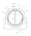
- FIG. 1 shows a liquefied gas carrier 1 including a double-shell tank 2A according to the first embodiment of the present invention.
- the liquefied gas carrier 1 includes a hull 11 on which the double-shell tank 2A is mounted, and a tank cover 12 that forms a holding space 13 around the double-shell tank 2A together with the hull 11. Including.
- the holding space 13 is filled with nitrogen gas.
- the holding space 13 may be filled with dry air or may be filled with the exhaust gas of the propulsion engine.
- the double shell tank 2A includes an inner tank 3 for storing liquefied gas and an outer tank 4 for accommodating the inner tank 3.
- the liquefied gas is LNG, liquefied nitrogen, liquefied hydrogen, liquefied helium, or the like.
- the double shell tank 2A includes a pipe tower (also referred to as a pump tower) 20 extending from the top of the outer tank 4 to the bottom of the inner tank 3.
- the inner tank 3 is spherical.
- the inner tank 3 does not necessarily have to be spherically symmetric, and may have a shape that approximates spherical symmetry.
- the inner tank 3 may have a shape that bulges 45 degrees above and / or 45 degrees below the center of the inner tank 3 as compared with spherical symmetry.
- the inner tank 3 may have a shape in which a short tubular body is sandwiched between the upper hemisphere and the lower hemisphere.
- the outer tank 4 is also spherical.
- the center of the outer tank 4 coincides with the center of the inner tank 3.
- the outer tank 4 does not necessarily have to be spherically symmetric, and may have a shape that approximates spherical symmetry.
- the outer tank 4 may have a shape that bulges 45 degrees above and / or 45 degrees below the center of the outer tank 4 as compared with spherical symmetry. ..
- the outer tank 4 does not necessarily have to be spherical, and may have any shape.
- the pipe tower 20 includes a box portion having a closed structure joined to the top portion of the outer tank 4, and a pillar portion extending downward from this box portion through the top portion of the inner tank 3.
- the pillar portion is a hollow columnar shape, and a through hole for communicating the inside and the outside is provided at an appropriate position in a portion of the pillar portion located in the inner tank 3.
- the pillar portion may be a square pillar.
- a pump for pumping liquefied gas is installed in the lower part of the pillar of the pipe tower 20.
- a liquid feed pipe and an electric pipe are connected to the pump, and these liquid feed pipes and electric pipes pass through the pillar portion of the pipe tower 20 and extend to the outside through the box portion of the pipe tower 20.
- the box portion of the pipe tower 20 is also penetrated by the air supply pipe 91.
- the air supply pipe 91 guides the boil-off gas generated by the vaporization of the liquefied gas in the inner tank 3 from the inner tank 3 to another device.
- Other devices include, for example, propulsion engines, power generation engines, reliquefaction devices, atmospheric release devices, and the like.
- the first heat insulating material 7 is packed in the space between the inner tank 3 and the outer tank 4.
- the first heat insulating material 7 completely covers the outer surface of the inner tank 3 and the inner surface of the outer tank 4. Further, the outer surface of the outer tank 4 is completely covered with the second heat insulating material 8.
- the first heat insulating material 7 may be, for example, a foam made of a resin such as polyurethane (PU) or phenol resin (PF), a granular material such as pearlite or a hollow glass body, or glass wool. It may be an inorganic fiber such as.
- PU polyurethane
- PF phenol resin
- a granular material such as pearlite or a hollow glass body, or glass wool. It may be an inorganic fiber such as.
- the second heat insulating material 8 is a foam made of a resin such as polyurethane or phenol resin, for example. Since the holding space 13 is filled with nitrogen gas as described above, when the second heat insulating material 8 is a foam, the nitrogen gas enters the second heat insulating material 8 from the holding space 13 and the second heat insulating material 8 is used. The voids in the material 8 are filled with nitrogen gas. Further, nitrogen gas may be supplied to the second heat insulating material 8 from a gas generator (not shown). When the holding space 13 is filled with dry air, the voids in the second heat insulating material 8 may also be filled with dry air.
- the space between the inner tank 3 and the outer tank 4 is filled with boil-off gas.
- Various methods can be adopted as a method of filling the space between the inner tank 3 and the outer tank 4 with the boil-off gas.
- the branch pipe 92 branches from the above-mentioned air supply pipe 91.
- the tip of the branch pipe 92 is open between the inner tank 3 and the outer tank 4.
- the air supply pipe 91 may be provided with various devices such as a compressor on the upstream side of the branch point of the branch pipe 92.
- the branch pipe 92 may be provided with a pressure adjusting valve, a check valve, or the like.
- the outer tank 4 is supported by the skirt 6 on the floor surface 11a of the hull 11, and the inner tank 3 is supported by the skirt 5 on the inner peripheral surface of the outer tank 4.
- the skirts 5 and 6 have a tubular shape with the vertical direction as the axial direction, the upper end of the skirt 6 is joined to the equator portion of the outer tank 4, and the upper end of the skirt 5 is joined to the equator portion of the inner tank 3. ..
- the structure that supports the outer tank 4 and the inner tank 3 can be changed as appropriate.
- the inner tank 3 may be suspended from the outer tank 4.
- the pressure in the space between the inner tank 3 and the outer tank 4 can be set to the same level as the atmospheric pressure. Therefore, the strength required for the outer tank 4 can be reduced.
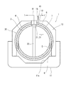
- the outer surface of the outer tank 4 does not necessarily have to be covered with the second heat insulating material 8, and may be exposed as shown in FIG. However, in this case, it is necessary to increase the distance from the inner tank 3 to the outer tank 4 to ensure the heat insulating performance.
- the outer surface of the outer tank 4 is covered with the second heat insulating material 8 as in the above embodiment, the outer surface of the outer tank 4 is not covered with the second heat insulating material 8 as compared with the case where the outer surface is not covered with the second heat insulating material 8.
- the distance from the inner tank 3 to the outer tank 4, in other words, the diameter of the outer tank 4 can be reduced. It should be noted that this modification can also be applied to the second embodiment and the third embodiment described later.
- FIG. 3 shows a liquefied gas carrier 1 including a double-shell tank 2B according to a second embodiment of the present invention.
- the same components as those in the first embodiment are designated by the same reference numerals, and duplicate description will be omitted.
- the space between the inner tank 3 and the outer tank 4 and the inside of the inner tank 3 are used.
- a plurality of communication holes 31 for communicating with the inner tank 3 are provided in the upper part of the inner tank 3.
- the number of communication holes 31 may be one.
- the first heat insulating material 7 is a foam.
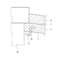
- each communication hole 31 is composed of a communication pipe 32 joined to the inner tank 3 around the pipe tower 20.
- the communication pipe 32 is a straight pipe, and at least one (two in the example) that prevents the liquefied gas in the inner tank 3 from leaking between the inner tank 3 and the outer tank 4 in the communication pipe 32.
- the protrusion 33 is provided.
- the outer tank 4 is provided with an on-off valve 16 so that the boil-off gas in the space can be discharged when the pressure in the space between the inner tank 3 and the outer tank 4 becomes too high. It is desirable that the discharge pipe 15 is connected.
- an umbrella 34 is provided in the inner tank 3 to prevent the liquefied gas in the inner tank 3 from flowing into the communication hole 31.
- the communication pipe 32 is provided with a plurality of through holes arranged in a matrix or staggered pattern, and one end (lower end) of the communication pipe 32 located in the inner tank 3 is closed by the closing plate 35. Has been done.
- the communication pipe 32 is an S-shaped pipe bent in an S-shape.
- One end of the communication pipe 32 located in the inner tank 3 opens upward, and the other end located between the inner tank 3 and the outer tank 4 opens downward.
- the communication pipe 32 is a V-shaped pipe bent in a V shape.
- One end of the communication pipe 32 located in the inner tank 3 opens diagonally downward, and the other end located between the inner tank 3 and the outer tank 4 opens diagonally upward.
- a film 36 that allows boil-off gas to permeate but does not allow liquefied gas to permeate is attached to the lower end of the communication pipe 32 that is a straight pipe.
- the membrane 36 is a porous ceramic membrane, a palladium membrane, or the like.
- the configuration shown in FIG. 10 is suitable when the first heat insulating material 7 is a granular material.
- the communication pipe 32 penetrates the outer tank 4 and is connected to the outer tank 4 by bending 180 degrees outside the outer tank 4.
- FIG. 11 shows a liquefied gas carrier 1 including a double-shell tank 2C according to a third embodiment of the present invention.
- the same components as those in the first embodiment and the second embodiment are designated by the same reference numerals, and duplicate description will be omitted.
- an opening 21 for securing a gap between the inner tank 3 and the pipe tower 20 is formed at the top of the inner tank 3, and the communication hole 31 is formed by the gap.
- a reinforcing ring 22 is joined to the inner tank 3 so as to border the opening 21.
- the inner diameter of the reinforcing ring 22 is larger than the diameter of the pillar portion of the pipe tower 20.
- a tubular partition plate 23 rises from the reinforcing ring 22, and an annular baffle plate 23a protruding inward in the radial direction is provided at the upper end of the partition plate 23. Further, a tubular breathable member (wire mesh or perforated plate) is arranged between the upper end of the partition plate 23 and the box portion (or the outer tank 4) of the pipe tower 20.
- the double-shell tanks 2A to 2C do not necessarily have to be included in the liquefied gas carrier 1, and may be included in the land equipment. Further, the space between the inner tank 3 and the outer tank 4 does not necessarily have to be filled with the first heat insulating material 7, and there may be no other than boil-off gas in the space.
Landscapes
- Engineering & Computer Science (AREA)
- Mechanical Engineering (AREA)
- General Engineering & Computer Science (AREA)
- Physics & Mathematics (AREA)
- Thermal Sciences (AREA)
- Chemical & Material Sciences (AREA)
- Combustion & Propulsion (AREA)
- Ocean & Marine Engineering (AREA)
- Filling Or Discharging Of Gas Storage Vessels (AREA)
Abstract
Description
図1に、本発明の第1実施形態に係る二重殻タンク2Aを含む液化ガス運搬船1を示す。この液化ガス運搬船1は、二重殻タンク2Aの他に、二重殻タンク2Aが搭載される船体11と、船体11と共に二重殻タンク2Aの周囲に保持空間13を形成するタンクカバー12を含む。
外槽4の外側面は必ずしも第2断熱材8で覆われている必要はなく、図2に示すように露出していてもよい。しかし、この場合には、内槽3から外槽4までの距離を大きくして断熱性能を確保する必要がある。これに対し、前記実施形態のように外槽4の外側面が第2断熱材8で覆われていれば、外槽4の外側面が第2断熱材8で覆われていない場合に比べて、内槽3から外槽4までの距離、換言すれば外槽4の直径を小さくすることができる。なお、本変形例は、後述する第2実施形態および第3実施形態にも適用可能である。
図3に、本発明の第2実施形態に係る二重殻タンク2Bを含む液化ガス運搬船1を示す。なお、本実施形態において、第1実施形態と同一構成要素には同一符号を付し、重複した説明は省略する。
前記実施形態と同様の効果は、図5乃至図10に示す構成でも得ることができる。
図11に、本発明の第3実施形態に係る二重殻タンク2Cを含む液化ガス運搬船1を示す。なお、本実施形態において、第1実施形態および第2実施形態と同一構成要素には同一符号を付し、重複した説明は省略する。
本発明は上述した実施形態に限定されるものではなく、本発明の要旨を逸脱しない範囲で種々の変形が可能である。
2 二重殻タンク
20 パイプタワー
21 開口
3 内槽
31 連通穴
32 連通管
33 突起
34 傘
35 閉塞板
36 膜
4 外槽
7,8 断熱材
91 気送管
92 分岐管
Claims (14)
- 液化ガスを貯留する球形の内槽と、
前記内槽を収容する外槽と、を備え、
前記内槽と前記外槽の間の空間には前記液化ガスの気化により発生したボイルオフガスが充填されている、二重殻タンク。 - 前記内槽から前記ボイルオフガスを他の機器へ導く気送管と、
前記気送管から分岐する分岐管であって、前記内槽と前記外槽の間で開口する先端を有する分岐管と、をさらに備える、請求項1に記載の二重殻タンク。 - 前記内槽には、前記内槽と前記外槽の間の空間と前記内槽の内部とを連通する連通穴が設けられている、請求項1に記載の二重殻タンク。
- 前記外槽の頂き部から前記内槽の底まで延びるパイプタワーをさらに備え、
前記連通穴は、前記パイプタワーの周囲で前記内槽に接合された連通管で構成されている、請求項3に記載の二重殻タンク。 - 前記連通管は、ストレート管であり、
前記連通管内には、前記内槽内の液化ガスが前記内槽と前記外槽の間へ漏れ出すことを防止する少なくとも1つの突起が設けられている、請求項4に記載の二重殻タンク。 - 前記連通管は、ストレート管であり、
前記内槽内には、前記内槽内の液化ガスが前記連通穴へ流入することを防止するための傘が設けられている、請求項4に記載の二重殻タンク。 - 前記連通管は、ストレート管であり、
前記連通管には、マトリクス状または千鳥状に並ぶ複数の貫通穴が設けられており、前記内槽内に位置する前記連通管の一端は閉塞板によって閉塞されている、請求項4に記載の二重殻タンク。 - 前記連通管は、前記内槽内に位置する一端が上向きに開口し、前記内槽と前記外槽の間に位置する他端が下向きに開口するようにS字状に屈曲したS字管である、請求項4に記載の二重殻タンク。
- 前記連通管は、前記内槽内に位置する一端が斜め下向きに開口し、前記内槽と前記外槽の間に位置する他端が斜め上向きに開口するようにV字状に屈曲したV字管である、請求項4に記載の二重殻タンク。
- 前記連通管は、ストレート管であり、
前記内槽内に位置する前記連通管の一端には、前記ボイルオフガスは透過可能であるが前記液化ガスは透過不能な膜が取り付けられている、請求項4に記載の二重殻タンク。 - 前記外槽の頂き部から前記内槽の底まで延びるパイプタワーをさらに備え、
前記内槽の頂き部には、前記パイプタワーとの間に隙間を確保するための開口が形成されており、
前記連通穴は、前記隙間で構成されている、請求項3に記載の二重殻タンク。 - 前記内槽と前記外槽の間の空間に詰め込まれて、前記内槽の外側面および前記外槽の内側面を覆う断熱材をさらに備える、請求項1~11の何れか一項に記載の二重殻タンク。
- 前記外槽の外側面を覆う断熱材をさらに備える、請求項1~12の何れか一項に記載の二重殻タンク。
- 液化ガスを貯留する球形の内槽、および前記内槽を収容する外槽、を含み、前記内槽と前記外槽の間の空間には前記液化ガスの気化により発生したボイルオフガスが充填されている、二重殻タンクを備える、液化ガス運搬船。
Priority Applications (5)
| Application Number | Priority Date | Filing Date | Title |
|---|---|---|---|
| CN201980095113.5A CN113661355B (zh) | 2019-04-05 | 2019-04-05 | 双层壳罐和液化气搬运船 |
| PCT/JP2019/015227 WO2020202578A1 (ja) | 2019-04-05 | 2019-04-05 | 二重殻タンクおよび液化ガス運搬船 |
| EP19922738.0A EP3951243A4 (en) | 2019-04-05 | 2019-04-05 | DOUBLE-WALLED TANK AND LIQUID CARRIER |
| JP2021511074A JP7365400B2 (ja) | 2019-04-05 | 2019-04-05 | 二重殻タンクおよび液化ガス運搬船 |
| KR1020217033824A KR102626816B1 (ko) | 2019-04-05 | 2019-04-05 | 이중각 탱크 및 액화 가스 운반선 |
Applications Claiming Priority (1)
| Application Number | Priority Date | Filing Date | Title |
|---|---|---|---|
| PCT/JP2019/015227 WO2020202578A1 (ja) | 2019-04-05 | 2019-04-05 | 二重殻タンクおよび液化ガス運搬船 |
Publications (1)
| Publication Number | Publication Date |
|---|---|
| WO2020202578A1 true WO2020202578A1 (ja) | 2020-10-08 |
Family
ID=72667298
Family Applications (1)
| Application Number | Title | Priority Date | Filing Date |
|---|---|---|---|
| PCT/JP2019/015227 Ceased WO2020202578A1 (ja) | 2019-04-05 | 2019-04-05 | 二重殻タンクおよび液化ガス運搬船 |
Country Status (5)
| Country | Link |
|---|---|
| EP (1) | EP3951243A4 (ja) |
| JP (1) | JP7365400B2 (ja) |
| KR (1) | KR102626816B1 (ja) |
| CN (1) | CN113661355B (ja) |
| WO (1) | WO2020202578A1 (ja) |
Cited By (10)
| Publication number | Priority date | Publication date | Assignee | Title |
|---|---|---|---|---|
| WO2022211089A1 (ja) | 2021-03-31 | 2022-10-06 | 川崎重工業株式会社 | ガス処理システムおよび船舶 |
| WO2023182363A1 (ja) * | 2022-03-23 | 2023-09-28 | 川崎重工業株式会社 | 液化ガス貯蔵タンクのクールダウン方法 |
| WO2023182366A1 (ja) * | 2022-03-23 | 2023-09-28 | 川崎重工業株式会社 | 液化ガス貯蔵タンクのクールダウン方法 |
| WO2023182365A1 (ja) * | 2022-03-23 | 2023-09-28 | 川崎重工業株式会社 | 液化ガス貯蔵タンクのクールダウン方法 |
| WO2023199428A1 (ja) * | 2022-04-13 | 2023-10-19 | 川崎重工業株式会社 | 液化ガス貯蔵タンク |
| KR20230160381A (ko) | 2021-03-31 | 2023-11-23 | 카와사키 주코교 카부시키 카이샤 | 다중각 탱크, 선박 및 가스압 조정 방법 |
| JPWO2024069966A1 (ja) * | 2022-09-30 | 2024-04-04 | ||
| WO2024166241A1 (ja) * | 2023-02-08 | 2024-08-15 | 川崎重工業株式会社 | 液体水素貯蔵設備、浮体構造物、及び多重殻タンクの槽間ガス供給方法 |
| KR20250065662A (ko) | 2022-09-30 | 2025-05-13 | 카와사키 주코교 카부시키 카이샤 | 액체 수소 탱크 및 그 운전 방법 |
| WO2025158516A1 (ja) * | 2024-01-23 | 2025-07-31 | 川崎重工業株式会社 | 閉区画付き構造物およびガス置換方法 |
Families Citing this family (1)
| Publication number | Priority date | Publication date | Assignee | Title |
|---|---|---|---|---|
| NO348617B1 (en) * | 2022-12-22 | 2025-03-31 | Moss Maritime As | A liquefied gas storage tank and a method for manufacturing said tank |
Citations (6)
| Publication number | Priority date | Publication date | Assignee | Title |
|---|---|---|---|---|
| JPS58156800A (ja) * | 1982-03-09 | 1983-09-17 | Jgc Corp | 二重殻低温タンク |
| JPH1182889A (ja) * | 1997-09-10 | 1999-03-26 | I H I Plantec:Kk | 竪型断熱低温タンク |
| JPH11278584A (ja) * | 1998-03-31 | 1999-10-12 | Ishii Iron Works Co Ltd | 二重殻貯槽の内槽支持構造 |
| US20090308083A1 (en) * | 2007-03-09 | 2009-12-17 | Bayerische Motoren Werke Aktiengesellschaft | Method for Filling a Pressure Vessel, Provided for a Cryogenic Storage Medium, in particular Hydrogen |
| JP2016124385A (ja) * | 2014-12-26 | 2016-07-11 | 川崎重工業株式会社 | 液化ガス運搬船 |
| JP2017194166A (ja) * | 2013-06-21 | 2017-10-26 | 川崎重工業株式会社 | 液化ガス保持タンクおよび液化ガス運搬船 |
Family Cites Families (8)
| Publication number | Priority date | Publication date | Assignee | Title |
|---|---|---|---|---|
| JP2676754B2 (ja) * | 1988-01-14 | 1997-11-17 | ヤマハ株式会社 | 自動演奏記録装置 |
| JPH02195099A (ja) | 1989-01-24 | 1990-08-01 | Mitsubishi Heavy Ind Ltd | 2重球形タンクの断熱支持装置 |
| JP2004028238A (ja) | 2002-06-26 | 2004-01-29 | Mitsubishi Heavy Ind Ltd | タンク |
| JP5568139B2 (ja) * | 2010-10-22 | 2014-08-06 | デウー シップビルディング アンド マリン エンジニアリング カンパニー リミテッド | 液化天然ガスの貯蔵容器 |
| CN105102316B (zh) * | 2013-04-23 | 2017-03-08 | 川崎重工业株式会社 | 船舶用储罐的支持结构以及液化气体运输船 |
| CN205191196U (zh) * | 2015-11-04 | 2016-04-27 | 河南开利空分设备集团有限公司 | 保温、安全的低温液体储槽装置 |
| WO2017108756A1 (en) * | 2015-12-22 | 2017-06-29 | Shell Internationale Research Maatschappij B.V. | Ship containment system for liquified gases |
| JP6909634B2 (ja) | 2017-05-19 | 2021-07-28 | 川崎重工業株式会社 | 低温液化ガス貯蔵タンク |
-
2019
- 2019-04-05 JP JP2021511074A patent/JP7365400B2/ja active Active
- 2019-04-05 EP EP19922738.0A patent/EP3951243A4/en active Pending
- 2019-04-05 WO PCT/JP2019/015227 patent/WO2020202578A1/ja not_active Ceased
- 2019-04-05 CN CN201980095113.5A patent/CN113661355B/zh active Active
- 2019-04-05 KR KR1020217033824A patent/KR102626816B1/ko active Active
Patent Citations (6)
| Publication number | Priority date | Publication date | Assignee | Title |
|---|---|---|---|---|
| JPS58156800A (ja) * | 1982-03-09 | 1983-09-17 | Jgc Corp | 二重殻低温タンク |
| JPH1182889A (ja) * | 1997-09-10 | 1999-03-26 | I H I Plantec:Kk | 竪型断熱低温タンク |
| JPH11278584A (ja) * | 1998-03-31 | 1999-10-12 | Ishii Iron Works Co Ltd | 二重殻貯槽の内槽支持構造 |
| US20090308083A1 (en) * | 2007-03-09 | 2009-12-17 | Bayerische Motoren Werke Aktiengesellschaft | Method for Filling a Pressure Vessel, Provided for a Cryogenic Storage Medium, in particular Hydrogen |
| JP2017194166A (ja) * | 2013-06-21 | 2017-10-26 | 川崎重工業株式会社 | 液化ガス保持タンクおよび液化ガス運搬船 |
| JP2016124385A (ja) * | 2014-12-26 | 2016-07-11 | 川崎重工業株式会社 | 液化ガス運搬船 |
Cited By (19)
| Publication number | Priority date | Publication date | Assignee | Title |
|---|---|---|---|---|
| KR20230160381A (ko) | 2021-03-31 | 2023-11-23 | 카와사키 주코교 카부시키 카이샤 | 다중각 탱크, 선박 및 가스압 조정 방법 |
| JP2022157755A (ja) * | 2021-03-31 | 2022-10-14 | 川崎重工業株式会社 | ガス処理システムおよび船舶 |
| JP7749336B2 (ja) | 2021-03-31 | 2025-10-06 | 川崎重工業株式会社 | ガス処理システムおよび船舶 |
| CN117120765A (zh) * | 2021-03-31 | 2023-11-24 | 川崎重工业株式会社 | 气体处理系统和船舶 |
| WO2022211089A1 (ja) | 2021-03-31 | 2022-10-06 | 川崎重工業株式会社 | ガス処理システムおよび船舶 |
| WO2023182365A1 (ja) * | 2022-03-23 | 2023-09-28 | 川崎重工業株式会社 | 液化ガス貯蔵タンクのクールダウン方法 |
| JP2023140782A (ja) * | 2022-03-23 | 2023-10-05 | 川崎重工業株式会社 | 液化ガス貯蔵タンクのクールダウン方法 |
| WO2023182366A1 (ja) * | 2022-03-23 | 2023-09-28 | 川崎重工業株式会社 | 液化ガス貯蔵タンクのクールダウン方法 |
| JP7837189B2 (ja) | 2022-03-23 | 2026-03-30 | 川崎重工業株式会社 | 液化ガス貯蔵タンクのクールダウン方法 |
| WO2023182363A1 (ja) * | 2022-03-23 | 2023-09-28 | 川崎重工業株式会社 | 液化ガス貯蔵タンクのクールダウン方法 |
| WO2023199428A1 (ja) * | 2022-04-13 | 2023-10-19 | 川崎重工業株式会社 | 液化ガス貯蔵タンク |
| KR20240154603A (ko) | 2022-04-13 | 2024-10-25 | 카와사키 주코교 카부시키 카이샤 | 액화가스 저장탱크 |
| KR20250065662A (ko) | 2022-09-30 | 2025-05-13 | 카와사키 주코교 카부시키 카이샤 | 액체 수소 탱크 및 그 운전 방법 |
| KR20250065663A (ko) | 2022-09-30 | 2025-05-13 | 카와사키 주코교 카부시키 카이샤 | 다중각 탱크 |
| JPWO2024069966A1 (ja) * | 2022-09-30 | 2024-04-04 | ||
| JP7842233B2 (ja) | 2022-09-30 | 2026-04-07 | 川崎重工業株式会社 | 多重殻タンク |
| KR20250136368A (ko) | 2023-02-08 | 2025-09-16 | 카와사키 주코교 카부시키 카이샤 | 액체 수소 저장 설비, 부체 구조물 및 다중각 탱크의 조간 가스 공급 방법 |
| WO2024166241A1 (ja) * | 2023-02-08 | 2024-08-15 | 川崎重工業株式会社 | 液体水素貯蔵設備、浮体構造物、及び多重殻タンクの槽間ガス供給方法 |
| WO2025158516A1 (ja) * | 2024-01-23 | 2025-07-31 | 川崎重工業株式会社 | 閉区画付き構造物およびガス置換方法 |
Also Published As
| Publication number | Publication date |
|---|---|
| KR102626816B1 (ko) | 2024-01-18 |
| KR20210141627A (ko) | 2021-11-23 |
| CN113661355B (zh) | 2023-03-28 |
| JP7365400B2 (ja) | 2023-10-19 |
| JPWO2020202578A1 (ja) | 2020-10-08 |
| CN113661355A (zh) | 2021-11-16 |
| EP3951243A1 (en) | 2022-02-09 |
| EP3951243A4 (en) | 2022-11-16 |
Similar Documents
| Publication | Publication Date | Title |
|---|---|---|
| JP7365400B2 (ja) | 二重殻タンクおよび液化ガス運搬船 | |
| KR102707025B1 (ko) | 액화가스 저장탱크의 펌프타워 | |
| JP7312815B2 (ja) | 液化ガスタンクおよび液化ガス運搬船 | |
| CN111174082B (zh) | 立式船用燃料罐 | |
| JP7190275B2 (ja) | タンクのガス置換方法および装置 | |
| JP2025123561A (ja) | 多重殻タンク | |
| KR102782178B1 (ko) | 액화가스 저장탱크의 펌프타워 지지 구조물 | |
| KR102754072B1 (ko) | 스프레잉 파이프를 포함하는 액화가스 저장탱크의 펌프타워 | |
| EP3951244B1 (en) | Liquefied gas storage structure and liquefied gas carrier ship | |
| WO2022210835A1 (ja) | 多重殻タンク及び船舶 | |
| KR102837575B1 (ko) | 벤트 마스트 | |
| CN118946498A (zh) | 液化气贮存罐单元 | |
| KR102729241B1 (ko) | 액화가스 저장탱크의 펌프타워 | |
| KR102729240B1 (ko) | 액화가스 저장탱크의 펌프타워 | |
| KR102707024B1 (ko) | 이중배관 구조의 충전용 파이프를 포함하는 액화가스 저장탱크의 펌프타워 | |
| KR20190078923A (ko) | Lng 연료 선박 | |
| KR102754070B1 (ko) | 액화가스 저장탱크의 펌프타워 | |
| KR102728680B1 (ko) | 액화가스 저장탱크의 펌프타워 | |
| KR102728682B1 (ko) | 액화가스 저장탱크의 펌프타워 지지 구조 | |
| KR102694833B1 (ko) | 이중배관 구조의 충전용 파이프를 포함하는 액화가스 저장탱크의 쿨다운 방법 | |
| JP2025032895A (ja) | 三重殻タンク | |
| JP2025032896A (ja) | 三重殻タンク | |
| CN121778089A (zh) | 一种组合式lng透气桅 | |
| JP2020034138A (ja) | 管の開口部の保護構造 | |
| KR200289889Y1 (ko) | 새로운 엘엔지선의 탱크 시스템 |
Legal Events
| Date | Code | Title | Description |
|---|---|---|---|
| 121 | Ep: the epo has been informed by wipo that ep was designated in this application |
Ref document number: 19922738 Country of ref document: EP Kind code of ref document: A1 |
|
| ENP | Entry into the national phase |
Ref document number: 2021511074 Country of ref document: JP Kind code of ref document: A |
|
| NENP | Non-entry into the national phase |
Ref country code: DE |
|
| ENP | Entry into the national phase |
Ref document number: 20217033824 Country of ref document: KR Kind code of ref document: A |
|
| ENP | Entry into the national phase |
Ref document number: 2019922738 Country of ref document: EP Effective date: 20211105 |