WO2020202612A1 - 画像処理装置、方法およびプログラム - Google Patents
画像処理装置、方法およびプログラム Download PDFInfo
- Publication number
- WO2020202612A1 WO2020202612A1 PCT/JP2019/041480 JP2019041480W WO2020202612A1 WO 2020202612 A1 WO2020202612 A1 WO 2020202612A1 JP 2019041480 W JP2019041480 W JP 2019041480W WO 2020202612 A1 WO2020202612 A1 WO 2020202612A1
- Authority
- WO
- WIPO (PCT)
- Prior art keywords
- specific structure
- composite
- image
- pixels
- tomographic images
- Prior art date
- Legal status (The legal status is an assumption and is not a legal conclusion. Google has not performed a legal analysis and makes no representation as to the accuracy of the status listed.)
- Ceased
Links
Images






Classifications
-
- A—HUMAN NECESSITIES
- A61—MEDICAL OR VETERINARY SCIENCE; HYGIENE
- A61B—DIAGNOSIS; SURGERY; IDENTIFICATION
- A61B6/00—Apparatus or devices for radiation diagnosis; Apparatus or devices for radiation diagnosis combined with radiation therapy equipment
- A61B6/50—Apparatus or devices for radiation diagnosis; Apparatus or devices for radiation diagnosis combined with radiation therapy equipment specially adapted for specific body parts; specially adapted for specific clinical applications
- A61B6/502—Apparatus or devices for radiation diagnosis; Apparatus or devices for radiation diagnosis combined with radiation therapy equipment specially adapted for specific body parts; specially adapted for specific clinical applications for diagnosis of breast, i.e. mammography
-
- G—PHYSICS
- G06—COMPUTING OR CALCULATING; COUNTING
- G06T—IMAGE DATA PROCESSING OR GENERATION, IN GENERAL
- G06T7/00—Image analysis
- G06T7/0002—Inspection of images, e.g. flaw detection
- G06T7/0012—Biomedical image inspection
-
- A—HUMAN NECESSITIES
- A61—MEDICAL OR VETERINARY SCIENCE; HYGIENE
- A61B—DIAGNOSIS; SURGERY; IDENTIFICATION
- A61B6/00—Apparatus or devices for radiation diagnosis; Apparatus or devices for radiation diagnosis combined with radiation therapy equipment
- A61B6/02—Arrangements for diagnosis sequentially in different planes; Stereoscopic radiation diagnosis
- A61B6/025—Tomosynthesis
-
- G—PHYSICS
- G06—COMPUTING OR CALCULATING; COUNTING
- G06T—IMAGE DATA PROCESSING OR GENERATION, IN GENERAL
- G06T2207/00—Indexing scheme for image analysis or image enhancement
- G06T2207/10—Image acquisition modality
- G06T2207/10072—Tomographic images
-
- G—PHYSICS
- G06—COMPUTING OR CALCULATING; COUNTING
- G06T—IMAGE DATA PROCESSING OR GENERATION, IN GENERAL
- G06T2207/00—Indexing scheme for image analysis or image enhancement
- G06T2207/10—Image acquisition modality
- G06T2207/10072—Tomographic images
- G06T2207/10081—Computed x-ray tomography [CT]
-
- G—PHYSICS
- G06—COMPUTING OR CALCULATING; COUNTING
- G06T—IMAGE DATA PROCESSING OR GENERATION, IN GENERAL
- G06T2207/00—Indexing scheme for image analysis or image enhancement
- G06T2207/30—Subject of image; Context of image processing
- G06T2207/30004—Biomedical image processing
- G06T2207/30068—Mammography; Breast
-
- G—PHYSICS
- G06—COMPUTING OR CALCULATING; COUNTING
- G06T—IMAGE DATA PROCESSING OR GENERATION, IN GENERAL
- G06T2207/00—Indexing scheme for image analysis or image enhancement
- G06T2207/30—Subject of image; Context of image processing
- G06T2207/30004—Biomedical image processing
- G06T2207/30096—Tumor; Lesion
Definitions
- This disclosure relates to image processing devices, methods and programs.
- tomosynthesis photography As a method of photographing a radiation image, so-called tomosynthesis photography is known in which radiation is sequentially irradiated from each of a plurality of irradiation positions having different irradiation angles and a plurality of projected images are taken by a radiation detector for each irradiation position. Further, there is known a technique of generating a tomographic image by a reconstruction process from a plurality of projected images acquired by tomosynthesis imaging.
- CAD Computer Aided Diagnosis
- CAD Computer Aided Diagnosis
- diagnostically important structures such as spicula and tumors are extracted from breast images using CAD.
- a method of extracting a region of interest including a lesion by CAD and synthesizing the extracted region of interest on a composite 2D image has been proposed (see US Pat. No. 8,983,156).
- a method has also been proposed in which the characteristics of common regions in a plurality of images including tomographic images are compared, the image having the best characteristics is identified, and the common regions of specially made images are combined to generate a composite two-dimensional image.
- a method has been proposed in which an edge is detected from a tomographic image, the detected edge is expanded to generate a weighted region, and a composite two-dimensional image is generated in consideration of the weight of the weighted region (US Pat. No. 1). See specification 10140715).
- a linear structure such as spicula is a structure that is important for diagnosis (hereinafter referred to as a specific structure), so it is necessary to include it in the composite two-dimensional image so as to be clear.
- a specific structure a structure that is important for diagnosis
- the extracted regions of interest or structures are linear when composited onto a composite two-dimensional image.
- the signal values of the structure are averaged. Therefore, the linear structure may be buried in other regions on the composite two-dimensional image, making it difficult to see. Further, in the method described in US Pat. No.
- edges such as normal mammary glands included in upper and lower tomographic images of a linear structure such as spicula are detected. Therefore, in a synthetic two-dimensional image, The edges of the mammary glands and the spicula overlap, making it difficult to see the spicula. Further, in the method described in US Pat. No. 10,140,715, the detected edges of the mammary glands and the like may overlap, and a structure that looks like a spicula may appear in the synthetic two-dimensional image.
- the present disclosure has been made in view of the above circumstances, and an object of the present disclosure is to make it easier to see a specific structure included in a tomographic image in a composite two-dimensional image.
- the image processing apparatus includes a structure extraction unit that extracts a specific structure from each of a plurality of tomographic images representing a plurality of tomographic surfaces of a subject. It is provided with a compositing unit that generates a composite two-dimensional image from a plurality of tomographic images by making the weight of pixels of a specific structure in each of the plurality of tomographic images larger than the weights of pixels other than the specific structure.
- the compositing unit sets the weight of the corresponding pixel corresponding to the specific structure included in the other tomographic image in the pixels other than the specific structure in each of the plurality of tomographic images. It may be smaller than the weight of the pixel of.
- the compositing unit may set the weight of the corresponding pixel to 0.
- the compositing unit may set the weight of the specific structure in each of the plurality of tomographic images to 1.
- the compositing unit may normalize the pixel value of the specific structure on the composite two-dimensional image based on the maximum value of the pixel value that the composite two-dimensional image can take.
- the compositing unit may generate a composite two-dimensional image by weighting and adding the pixel values of the corresponding pixels of a plurality of tomographic images by weights. ..
- tomosynthesis imaging is performed in which the radiation source is moved relative to the detection surface of the detection unit and the subject is irradiated with radiation at a plurality of radiation source positions due to the movement of the radiation source.
- An image acquisition unit that acquires a plurality of projected images corresponding to each of a plurality of source positions, which is generated by the operation of It further includes a reconstruction unit that generates a plurality of tomographic images by reconstructing a plurality of projected images.
- the image processing apparatus is further provided with a misalignment correction unit for correcting misalignment between a plurality of projected images.
- the reconstructing unit may generate a plurality of tomographic images by reconstructing a plurality of projected images corrected for misalignment.
- the compositing unit may perform smoothing processing on the boundary of a specific structure in the composite two-dimensional image.
- the “smoothing process” means a process of smoothly changing the pixel value near the boundary of a specific structure to match the pixel value of the background in contact with the boundary.
- the compositing unit in each of the plurality of tomographic images, has a specific structure for pixels other than the corresponding pixels corresponding to the pixels of the specific structure and the specific structure included in the other tomographic images.
- the weighting of the noise pixels, which are more affected by noise than the above, may be lowered, or the noise pixels may be excluded to generate a composite two-dimensional image.
- the subject may be a breast and the specific structure may be a spicula or a mass.
- the image processing method extracts a specific structure from each of a plurality of tomographic images representing a plurality of tomographic surfaces of a subject.
- the weight of the pixel of the specific structure in each of the plurality of tomographic images is made larger than the weight of the pixel of the non-specific structure to generate a composite two-dimensional image from the plurality of tomographic images.
- image processing devices include a memory for storing an instruction to be executed by a computer and a memory.
- the processor comprises a processor configured to execute a stored instruction.
- a specific structure is extracted from each of multiple tomographic images representing multiple tomographic surfaces of the subject.
- the weight of the pixel of the specific structure in each of the plurality of tomographic images is made larger than the weight of the pixel of the non-specific structure, and the process of generating the composite two-dimensional image from the plurality of tomographic images is executed.
- the view of the radiation imaging apparatus from the direction of arrow A in FIG. The figure which shows the schematic structure of the image processing apparatus realized by installing the image processing program in the computer in this embodiment.
- Diagram to illustrate the acquisition of projected images Diagram to explain the generation of tomographic images
- Diagram to explain the extraction of specific structures from tomographic images Diagram for explaining the generation of a composite 2D image
- Diagram to illustrate weight setting Diagram to illustrate weight setting
- the figure for demonstrating the generation of the composite 2D image by the set weight Flowchart showing processing performed in this embodiment Flowchart showing processing performed in this embodiment Flowchart showing processing performed in this embodiment
- the figure which shows the probability near a specific structure at the time of a specific structure detection The figure which shows the weight of a specific structure at the time of performing a smoothing process
- FIG. 1 is a schematic configuration diagram of a radiation imaging device to which the image processing device according to the embodiment of the present disclosure is applied
- FIG. 2 is a view of the radiation imaging device viewed from the direction of arrow A in FIG.
- the radiographic image capturing apparatus 1 captures a breast M, which is a subject, from a plurality of radiation source positions in order to perform tomosynthesis imaging of the breast and generate a tomographic image, and acquires a plurality of radiographic images, that is, a plurality of projected images. It is a mammography imaging device.
- the radiographic image capturing apparatus 1 includes a photographing unit 10, a computer 2 connected to the photographing unit 10, a display unit 3 connected to the computer 2, and an input unit 4.
- the photographing unit 10 includes an arm unit 12 connected to a base (not shown) by a rotating shaft 11.
- An imaging table 13 is attached to one end of the arm portion 12, and an irradiation unit 14 is attached to the other end so as to face the photographing table 13.
- the arm portion 12 is configured so that only the end portion to which the radiation irradiation unit 14 is attached can be rotated, whereby the imaging table 13 can be fixed and only the radiation irradiation unit 14 can be rotated. It has become.
- the rotation of the arm portion 12 is controlled by the computer 2.
- a radiation detector 15 such as a flat panel detector is provided inside the photographing table 13.
- the radiation detector 15 has a radiation detection surface 15A. Further, inside the photographing table 13, a charge amplifier that converts the charge signal read from the radiation detector 15 into a voltage signal, a correlated double sampling circuit that samples the voltage signal output from the charge amplifier, and a voltage signal. A circuit board or the like provided with an AD (Analog Digital) conversion unit or the like for converting the voltage into a digital signal is also installed.
- the radiation detector 15 corresponds to the detection unit. Further, in the present embodiment, the radiation detector 15 is used as the detection unit, but the radiation detector 15 is not limited as long as it can detect the radiation and convert it into an image.
- the radiation detector 15 can repeatedly record and read a radiation image, and may use a so-called direct type radiation detector that directly converts radiation such as X-rays into a charge, or radiation. You may use a so-called indirect radiation detector that once converts the visible light into visible light and then converts the visible light into a charge signal. Further, as a radiation image signal reading method, a so-called TFT reading method in which a radiation image signal is read by turning on and off a TFT (Thin Film Transistor) switch, or a radiation image signal by irradiating the read light. It is desirable to use a so-called optical reading method in which
- the radiation source 16 is housed inside the radiation irradiation unit 14.
- the radiation source 16 emits X-rays as radiation, and the timing of irradiating the radiation from the radiation source 16 and the radiation generation conditions in the radiation source 16, that is, the selection of the material of the target and the filter, the tube voltage, the irradiation time, and the like are determined. It is controlled by the computer 2.
- a compression plate 17 which is arranged above the imaging table 13 and presses and presses the breast M, a support portion 18 which supports the compression plate 17, and a support portion 18 are vertically attached to FIGS. 1 and 2.
- a moving mechanism 19 for moving in a direction is provided. The distance between the compression plate 17 and the photographing table 13, that is, the compression thickness is input to the computer 2.
- the display unit 3 is a display device such as a CRT (Cathode Ray Tube) or a liquid crystal monitor, and displays a projected image, a tomographic image, a composite two-dimensional image, etc. acquired as described later, as well as a message necessary for operation. ..
- the display unit 3 may have a built-in speaker that outputs sound.
- the input unit 4 includes an input device such as a keyboard, a mouse, or a touch panel method, and receives an operation of the radiographic image capturing device 1 by an operator. It also accepts instructions for inputting various information such as shooting conditions and correcting information necessary for performing tomosynthesis shooting. In the present embodiment, each part of the radiographic imaging apparatus 1 operates according to the information input from the input unit 4 by the operator.
- the image processing program according to this embodiment is installed on the computer 2.
- the computer 2 may be a workstation or a personal computer directly operated by the operator, or may be a server computer connected to them via a network.
- the image processing program is recorded and distributed on a recording medium such as a DVD (Digital Versatile Disc) or a CD-ROM (Compact Disc Read Only Memory), and is installed in a computer from the recording medium.
- a recording medium such as a DVD (Digital Versatile Disc) or a CD-ROM (Compact Disc Read Only Memory)
- it is stored in the storage device of the server computer connected to the network or in the network storage in a state where it can be accessed from the outside, and is downloaded and installed in the computer upon request.
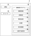
- FIG. 3 is a diagram showing a schematic configuration of an image processing apparatus realized by installing an image processing program according to the present embodiment on the computer 2.
- the image processing apparatus includes a CPU (Central Processing Unit) 21, a memory 22, and a storage 23 as a standard computer configuration.
- CPU Central Processing Unit
- the storage 23 is composed of a storage device such as a hard disk drive or an SSD (Solid State Drive), and stores various information including a program for driving each part of the radiation imaging apparatus 1 and an image processing program.
- a storage device such as a hard disk drive or an SSD (Solid State Drive)
- various information including a program for driving each part of the radiation imaging apparatus 1 and an image processing program.
- the projected image acquired by tomosynthesis imaging, the tomographic image generated as described later, and the composite two-dimensional image are also stored.
- the memory 22 temporarily stores a program or the like stored in the storage 23 in order to cause the CPU 21 to execute various processes.
- the image processing program causes the radiation image capturing apparatus 1 to perform tomosynthesis imaging, and acquires a plurality of projected images of the breast M corresponding to each of the plurality of source positions.
- Reconstruction processing that generates tomographic images at each of the multiple tomographic planes of the breast M that is the subject by reconstructing the projected image of, structure extraction processing that extracts a specific structure from each of the plurality of tomographic images, and a plurality of The weight of the pixel of the specific structure in each of the tomographic images is made larger than the weight of the pixel other than the specific structure, and the composite process of generating a composite two-dimensional image from a plurality of tomographic images, and the composite two-dimensional image display unit
- the display control process to be displayed in 3 is specified.
- the computer 2 functions as an image acquisition unit 31, a reconstruction unit 32, a structure extraction unit 33, a composition unit 34, and a display control unit 35.
- the image acquisition unit 31 moves the radiation source 16 by rotating the arm unit 12 around the rotation axis 11 when performing the image acquisition process, and is used for tomosynthesis imaging at a plurality of radiation source positions due to the movement of the radiation source 16.
- FIG. 4 is a diagram for explaining the acquisition of the projected image Gi.
- the radiation source 16 is moved to each source position of S1, S2, ..., Sn, and the radiation source 16 is driven at each source position to irradiate the breast M with radiation, and the breast M is irradiated.
- projected images G1, G2, ..., Gn are acquired corresponding to the source positions S1 to Sn.
- the same dose of radiation is applied to the breast M.
- the acquired plurality of projected images Gi are stored in the storage 23.
- a plurality of projected images Gi may be acquired by a program separate from the image processing program and stored in the storage 23 or an external storage device. In this case, the image acquisition unit 31 reads out a plurality of projected image Gis stored in the storage 23 or the external storage device from the storage 23 or the external storage device for reconstruction processing or the like.
- the radiation source position Sc is the radiation source position where the optical axis X0 of the radiation emitted from the radiation source 16 is orthogonal to the detection surface 15A of the radiation detector 15.
- the radiation source position Sc shall be referred to as a reference radiation source position Sc.
- the structure extraction unit 33 extracts a specific structure from a plurality of tomographic images Dj.
- the spicula and the mass contained in the breast M are extracted as specific structures.
- FIG. 6 is a diagram for explaining the extraction of a specific structure.
- the detection of a specific structure from the tomographic image Dk of one of the plurality of tomographic images Dj will be described.
- the tomographic image Dk includes the spicula and the mass on the tomographic surface of the breast M from which the tomographic image Dk was acquired as specific structures K1 to K3.
- the specific structure includes spicula, which is a linear structure around the tumor.
- the structure extraction unit 33 extracts a specific structure from the tomographic image Dk by using a known computer-aided diagnosis (CAD: Computer Aided Diagnosis, hereinafter referred to as CAD) algorithm.
- CAD Computer Aided Diagnosis
- a probability indicating that a pixel in the tomographic image Dj has a specific structure is derived, and when the probability is equal to or higher than a predetermined threshold value, the pixel is detected as a specific structure. Extraction of a specific structure is not limited to those using CAD.
- the specific structure may be extracted from the tomographic image Dk by filtering processing with a filter for extracting the specific structure or the like.
- the composite unit 34 is a composite two-dimensional image CG0 which is a pseudo two-dimensional image corresponding to a simple two-dimensional image taken by irradiating the breast M with radiation from the reference radiation source position Sc using a plurality of tomographic images Dj. To generate.
- the synthesis unit 34 shows the viewpoint direction from the reference radiation source position Sc toward the radiation detector 15, that is, FIG. 4 in a state where a plurality of tomographic images Dj are stacked.
- a composite two-dimensional image CG0 is generated by an addition method in which the pixel values of the corresponding pixels in each tomographic image Dj are weighted and added along the optical axis X0.
- the generation of the composite two-dimensional image CG0 is not limited to the addition method, and a known technique can be applied.
- the weight for each pixel at the time of weighting addition is basically set to 1 / m when the number of tomographic images Dj is m, and a composite two-dimensional image CG0 is generated.
- the weights of the pixels of the specific structure in each of the plurality of tomographic images Dj are made larger than the weights of the pixels other than the specific structure, and the composite two-dimensional image CG0 is generated.
- FIG. 8 is a diagram for explaining the setting of weights in the present embodiment.
- 10 tomographic images D1 to D10 are generated for explanation, the specific structure K1 is included in the tomographic images D2 to D4, and the specific structure K2 is included in the tomographic images D3 to D6.
- the specific structure K3 is included in the tomographic image D8.
- the specific structures K1 to K3 have a thickness in FIG. 8 for the sake of explanation, they are not actually thick.
- the specific structure K1 included in each of the tomographic images D2 to D4 is designated as the specific structure K1-2, K1-3, K1-4, respectively.
- the specific structure K2 included in each of the tomographic images D3 to D6 is designated as the specific structure K2-3, K2-4, K2-5, K2-6.
- the specific structure K1 shown in FIG. 8 is included over three tomographic images D2 to D4.
- the size of the specific structure K1-3 included in the tomographic image D3 is the largest.
- the synthesizing unit 34 makes the weight of the corresponding pixel corresponding to the specific structure K1 smaller than the weight of the pixels other than the corresponding pixel.
- the weight of the corresponding pixel which is a pixel in the corresponding region A1 on the tomographic images D1, D5 to D10 corresponding to the specific structure K1 shown in FIG. 8, is larger than the weight of the pixel in the region other than the corresponding region A1. Make it smaller.
- the weight of the corresponding pixel in the corresponding region A1 on the tomographic images D1, D5 to D10 is set to 0.
- the region of the specific structure K1-2 is smaller than the corresponding region A1. Therefore, the compositing unit 34 sets the weight of the pixels in the region other than the specific structure K1-2 in the corresponding region A1 of the tomographic image D2 to 0.
- the region of the specific structure K1-4 is smaller than the corresponding region A1. Therefore, the synthesis unit 34 also sets the weight of the pixels in the region other than the specific structure K1-4 in the corresponding region A1 of the tomographic image D4 to 0. The process of setting the weight will be described later.
- the specific structure K2 shown in FIG. 8 is included over four tomographic images D3 to D6. Further, the size of the specific structure K2-5 included in the tomographic image D5 is the largest.
- the synthesis unit 34 makes the weight of the corresponding pixel corresponding to the specific structure K2 smaller than the weight of the pixels other than the corresponding pixel. Specifically, the weight of the corresponding pixel, which is the pixel in the corresponding region A2 on the tomographic images D1, D2, D7 to D10 corresponding to the specific structure K2 shown in FIG. 8, is set to 0.
- the region of the specific structure K2-3 is smaller than the corresponding region A2. Therefore, the compositing unit 34 sets the weight of the pixels in the region other than the specific structure K2-3 in the corresponding region A2 of the tomographic image D3 to 0. Further, in the tomographic image D4, the region of the specific structure K2-4 is smaller than the corresponding region A2. Therefore, the compositing unit 34 sets the weight of the pixels in the region other than the specific structure K2-4 in the corresponding region A2 of the tomographic image D4 to 0. Further, in the tomographic image D6, the region of the specific structure K2-6 is smaller than the corresponding region A2. Therefore, the compositing unit 34 sets the weight of the pixels in the region other than the specific structure K2-6 in the corresponding region A2 of the tomographic image D6 to 0.
- the specific structure K3 shown in FIG. 8 is included in only one tomographic image D8.
- the synthesis unit 34 makes the weight of the corresponding pixel corresponding to the specific structure K3 smaller than the weight of the non-corresponding pixel in the tomographic images D1 to 7, D9, and D10 that do not include the specific structure K3. That is, the weight of the corresponding pixel in the corresponding region A3 on the tomographic images D1 to 7, D9, and D10 corresponding to the specific structure K3 shown in FIG. 8 is set to 0.
- the compositing unit 34 sets the weight to 1 for the pixels of the specific structures K1 to K3 in each of the plurality of tomographic images Dj.
- the total value of the weights of the pixels of the specific structure in the composite two-dimensional image CG0 becomes the number of pixels of the specific structure included in the corresponding pixels. That is, the pixel value of the specific structure in the composite two-dimensional image CG0 is the sum of the pixel values of the specific structure in each of the tomographic images Dj.
- FIG. 9 is a diagram for explaining the setting of weights for a specific structure.
- the weight may be set for the specific structures K2 and K3 in the same manner.
- the compositing unit 34 sets the weight to 1 for the pixels in the region of the specific structure K1 in the tomographic images D2 to D4.
- the weight of the pixel in the corresponding region A1 is 0. Therefore, on the composite two-dimensional image CG0, three specific structures K1-2 and K1-3 among the pixels in the corresponding region A1 corresponding to the specific structure K1.
- the total value of the weights is 3.
- the pixels in the region A12 in which only the two specific structures K1-2 and K1-3 in the tomographic images D2 and D3 overlap are the sum of the weights.
- the value is 2.
- the total weight value is 1.
- the number of tomographic images is 10 for the pixels in the region that does not overlap with any specific structure included in the other tomographic images D1 and D5 to D10. Therefore, if the noise pixels described later are not taken into consideration, the compositing unit 34 sets the weight of the pixels in this region to 1/10. Therefore, on the composite two-dimensional image CG0, the total value of the weights is 1 for the pixels in the region that does not overlap with any specific structure.
- the weight of the pixel of the specific structure included in each tomographic image Dj becomes larger than the weight of the pixel other than the specific structure.
- the pixel value of the specific structure is larger than the pixel value of the structure other than the specific structure. Therefore, in the composite two-dimensional image CG0 generated by the weights set as described above, the pixel values of the pixels in the corresponding region A10 have a value larger than that of the other regions, as shown in FIG. Become.
- the synthesis unit 34 has a noise component ratio in a region having a specific structure and a region other than the corresponding region corresponding to the specific structure (hereinafter referred to as another region).
- noise pixels For pixels that are highly affected by noise (hereinafter referred to as noise pixels), the weighting of the noise pixels is lowered or the noise pixels are excluded when the composite two-dimensional image CG0 is generated.
- the exclusion of noise pixels is equivalent to setting the weight of noise pixels to 0. In this embodiment, the weight for the noise pixel is set to 0.
- the synthesis unit 34 derives the average value of the pixel values of all the pixels to be added when the composite two-dimensional image CG0 is generated for the other regions of the plurality of tomographic images Dj, and each pixel. Pixels whose absolute value obtained by dividing the average value from the value is equal to or less than a predetermined threshold Th are regarded as noise pixels, and the weight for the noise pixels is set to 0.
- the threshold value Th may be determined in advance by an experiment, a simulation, or the like according to the magnitude of the superimposed noise.
- FIG. 11 is a diagram for explaining the generation of a composite two-dimensional image.
- the tomographic images D2 to D4 of the tomographic images D1 to D5 include specific structures K4-2, K4-3, and K4-4 representing the same specific structure, respectively.
- the specific structures K4-2, K4-3, and K4-4 spicula, which is a linear structure, exists around the tumor.
- the tomographic images D1, D2, and D5 contain noises N1, N2, and N5, respectively.
- the weight of the pixels of the specific structure K4-2, K4-3, K4-4 is larger than the weight of the pixels in the region other than the specific structure K4-2, K4-3, K4-4. ..
- the weights are set to 1, respectively.
- the weights of the pixels in the corresponding region corresponding to the specific structures K4-2, K4-3, and K4-4 in the tomographic images D1 and D5 are set to 0. Therefore, the signal value of the pixel of the specific structure K4 in the composite two-dimensional image CG0 is an addition value of only the signal values of the specific structures K4-2, K4-3, and K4-4 included in the tomographic images D2 to D4. Therefore, in the composite two-dimensional image CG0, the specific structure is not buried in other regions.
- the weight is 1/5. Further, for noise pixels, the weight is set to 0 at the time of synthesis. Therefore, the regions other than the specific structure K4 in the composite two-dimensional image CG0 have substantially the same signal values as the pixels in the regions other than the specific structure in the tomographic images D1 to D5, and noise is generated. It will be removed.
- the weight at the time of addition is set based on the value obtained by subtracting the number of noise pixels from the number of tomographic images. That is, when the composite two-dimensional image CG0 is generated by adding m tomographic images, if there are d noise pixels in the tomographic image Dj corresponding to a certain pixel on the composite two-dimensional image CG0, the pixel is The weight of is 1 / (md) instead of 1 / m.
- the pixel value of the specific structure on the composite two-dimensional image CG0 is the maximum value of the pixel values that the composite two-dimensional image CG0 can take. May exceed.
- the total value of the weights is 3 for the pixels in the region A11 in which all of the specific structures K1-2, K1-3, and K1-4 overlap.
- the maximum value of the pixel values that the composite two-dimensional image CG0 can take is 1024, and the specific structures K1-2 and K1-3.
- each pixel value of K1-4 is 512
- the pixel value in the composite two-dimensional image CG0 is 1536
- the maximum value of the pixel value that the composite two-dimensional image CG0 can take is larger than 1024.
- the pixel is in a state where the pixel value is saturated. Therefore, when the pixel value of the specific structure on the composite two-dimensional image CG0 is larger than the maximum value of the pixel value that the composite two-dimensional image CG0 can take, the compositing unit 34 determines the specific structure on the composite two-dimensional image CG0.
- the pixel values of the pixels in the region are normalized by the maximum value of the pixel values that the composite two-dimensional image CG0 can take.
- the pixel value in the composite two-dimensional image CG0 is 1536 and the value becomes the maximum value of the pixel value in the specific structure
- the pixel value in the specific structure is normalized so that the pixel value 1536 becomes 1024.
- the pixel values of all the pixels in the specific structure are normalized so as to be 1024/1536 times. This makes it possible to prevent saturation of the pixel values in the specific structure included in the composite two-dimensional image CG0.
- FIG. 12 is a flowchart showing the processing performed in the present embodiment.
- the input unit 4 receives an instruction from the operator to start processing, tomosynthesis imaging is performed, and the image acquisition unit 31 acquires a plurality of projected images Gi (step ST1).
- the reconstruction unit 32 generates a plurality of tomographic images Dj on the plurality of tomographic planes of the breast M by reconstructing the plurality of projected images Gi (step ST2).
- the number of tomographic images is m.
- the structure extraction unit 33 extracts a specific structure from each of the plurality of tomographic images Dj (step ST3).
- the compositing unit 34 sets the weights for generating the composite two-dimensional image CG0 for each pixel of the plurality of tomographic images Dj (weight setting process; step ST4).
- step ST13 the compositing unit 34 determines whether or not the corresponding pixel corresponding to the pixel of interest has a pixel having a specific structure in the tomographic image other than the kth tomographic image. Step ST15). When step ST15 is affirmed, the compositing unit 34 sets the weight of the pixel of interest to 0 (step ST16) and proceeds to step ST21. If step ST15 is denied, the compositing unit 34 determines whether or not the pixel of interest is a noise pixel (step ST17). When step ST17 is affirmed, the compositing unit 34 sets the weight of the pixel of interest to 0 (step ST18), and proceeds to step ST21.
- step ST17 When step ST17 is denied, the compositing unit 34 counts the number d of tomographic images in which the corresponding pixel corresponding to the pixel of interest is a noise pixel in the tomographic image other than the kth tomographic image (step ST19). ), Set the weight of the pixel of interest to 1 / (md) (step ST20), and proceed to step ST21.
- step ST21 the compositing unit 34 determines whether or not the weights of all the pixels are set for the kth tomographic image.
- step ST21 the pixel of interest is changed to the next pixel (step ST22), the process returns to step ST13, and the processes after step ST13 are repeated.
- step ST23 the weight setting process ends.
- the compositing unit 34 generates a composite two-dimensional image CG0 from a plurality of tomographic images Dk using the set weights (step ST5). At this time, if necessary, as described above, the pixel values of the pixels of the specific structure on the composite two-dimensional image CG0 are normalized by the maximum value of the pixel values of the composite two-dimensional image CG0. Then, the display control unit 35 displays the composite two-dimensional image CG0 on the display unit 3 (step ST6), and ends the process.
- the specific structure is extracted from each of the plurality of tomographic images Dj representing the tomographic plane of the breast M, and the weights of the pixels of the specific structure in each of the plurality of tomographic images Dj are set to other than the specific structure.
- the composite two-dimensional image CG0 is generated from a plurality of tomographic images Dj by making it larger than the weight of the pixels of. Therefore, in the composite two-dimensional image CG0, the specific structure is not buried in the region other than the specific structure. Therefore, according to the present embodiment, the specific structure can be easily seen in the composite two-dimensional image CG0.
- the structures such as spicula and tumor are high-intensity (white), and the other fats are low-intensity (black).
- the signal value of the corresponding pixel position in the tomographic image when the composite two-dimensional image CG0 is generated. Is equalized, so that the fat region contained in the composite two-dimensional image CG0 becomes whitish as compared with the simple two-dimensional image. Therefore, the texture of the composite two-dimensional image CG0 is different from the texture of the simple two-dimensional image. Further, in the method described in US Pat. No.
- edges such as normal mammary glands included in upper and lower tomographic images of a linear structure such as spicula are detected, and therefore, in the synthetic two-dimensional image CG0, ,
- the edges of the mammary glands and the spicula overlap, making it difficult to see the spicula.
- the detected edges of the mammary glands and the like may overlap, and a structure that looks like a spicula may appear in the synthetic two-dimensional image CG0.
- the weight of the corresponding pixel corresponding to the specific structure included in the other tomographic image is made smaller than the weight of the pixel other than the corresponding pixel, preferably 0. ..
- the composite two-dimensional image CG0 can have the same texture as the simple two-dimensional image.
- the composite two-dimensional image CG0 it is possible to prevent the specific structure from overlapping with the structure other than the specific structure, making the specific structure difficult to see. Further, it is possible to prevent a structure different from the specific structure, which looks like the specific structure, from appearing in the composite two-dimensional image CG0.
- a plurality of tomographic images are acquired by tomosynthesis imaging.
- Tomosynthesis imaging also has a problem that the reconstructed tomographic image is blurred due to the influence of the mechanical error of the imaging device and the body movement of the subject due to the time difference of imaging at each of the multiple source positions. .. If the tomographic image is blurred in this way, it becomes difficult to detect lesions such as minute calcifications, which are useful for early detection of breast cancer.
- a misalignment correction unit for correcting misalignment due to body movement or the like between a plurality of projected images acquired by tomosynthesis imaging. 36 may be provided.
- any method such as the method described in Japanese Patent Application Laid-Open No. 2016-064119 can be used.
- the method described in Japanese Patent Application Laid-Open No. 2016-064119 is a method for correcting a positional deviation between a plurality of projected images Gi so that the positions of the plurality of projected images Gis match.
- SIFT Scale-Invariant Feature Transform
- SURF Speeded Up Robust Features
- the minute calcification contained in the breast M does not disappear in the tomographic image. Therefore, in the composite two-dimensional image CG0, the abnormal portion can be completely expressed.
- the compositing unit may perform a smoothing process on the boundary of the specific structure when generating the composite two-dimensional image CG0.
- the smoothing process means a process of smoothly changing the pixel value near the boundary of a specific structure to match the pixel value of the background in contact with the boundary.
- the smoothing process is performed by changing the weight near the boundary of the specific structure. The weight at this time may be set based on the probability when the structure extraction unit 33 detects the specific structure.
- the distribution of the probabilities output by the structure extraction unit 33 is shown in FIG.
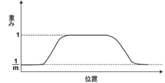
- the probability output by the structure extraction unit 33 becomes smaller toward the periphery of the specific structure, and the region of the probability of becoming the threshold value Th1 or more is detected as the specific structure. Therefore, as shown in FIG. 17, the compositing unit 34 sets the weight for the specific structure so as to gradually decrease from 1 to 1 / m as the pixels around the specific structure correspond to the probability of the specific structure.
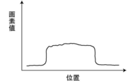
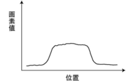
- the specific structure having an unnaturally clear pixel value at the boundary with the surroundings has a pixel value at which the boundary with the surroundings changes smoothly as shown in FIG. Become.
- the boundary of the specific structure gradually approaches the pixel value of the background in which the pixel value of the specific structure is adjacent. Therefore, it is possible to generate a composite two-dimensional image CG0 in which a specific structure and its background intersect more naturally.
- the smoothing process is not limited to the method using the weight derived as described above.
- the smoothing process may be performed by filtering the boundary of the specific structure included in the composite two-dimensional image CG0 with a low-pass filter.
- the pixels in the corresponding region corresponding to the specific structure and the specific structure of the other tomographic image are noise pixels. It is not limited to.
- a value 1 / m obtained by dividing 1 by the number m of tomographic images may be set as a weight without determining whether or not the pixel is a noise pixel.
- the weight of the specific structure is set to 1 in each of the tomographic images Dj, but the weight is not limited to this.
- the weight of the pixels of the specific structure may be set to 1 / c.
- the compositing unit 34 sets the weights of the pixels having the specific structure so that the total weights are 1 when the composite two-dimensional image CG0 is generated.
- the addition method is applied as a method in which the synthesis unit 34 generates a composite two-dimensional image, but as described above, other known techniques can be applied. For example, a so-called shortest path method may be applied, which uses the minimum value in the corresponding pixel of each tomographic image.
- the radiation in the above embodiment is not particularly limited, and ⁇ rays, ⁇ rays, etc. can be applied in addition to X-rays.
- a processing unit that executes various processes such as an image acquisition unit 31, a reconstruction unit 32, a structure extraction unit 33, a composition unit 34, a display control unit 35, and a misalignment correction unit 36.
- various processors Processors
- the various processors include a CPU, which is a general-purpose processor that executes software (program) and functions as various processing units, and a circuit after manufacturing an FPGA (Field Programmable Gate Array) or the like.
- Dedicated electricity which is a processor with a circuit configuration specially designed to execute specific processing such as programmable logic device (PLD), ASIC (Application Specific Integrated Circuit), which is a processor whose configuration can be changed. Circuits and the like are included.
- One processing unit may be composed of one of these various processors, or a combination of two or more processors of the same type or different types (for example, a combination of a plurality of FPGAs or a combination of a CPU and an FPGA). ) May be configured. Further, a plurality of processing units may be configured by one processor.
- one processor is configured by combining one or more CPUs and software. There is a form in which this processor functions as a plurality of processing units.
- SoC System On Chip
- the various processing units are configured by using one or more of the various processors as a hardware structure.
- circuitry in which circuit elements such as semiconductor elements are combined can be used.
Landscapes
- Engineering & Computer Science (AREA)
- Health & Medical Sciences (AREA)
- Life Sciences & Earth Sciences (AREA)
- Medical Informatics (AREA)
- Physics & Mathematics (AREA)
- Radiology & Medical Imaging (AREA)
- Nuclear Medicine, Radiotherapy & Molecular Imaging (AREA)
- General Health & Medical Sciences (AREA)
- Surgery (AREA)
- Public Health (AREA)
- Animal Behavior & Ethology (AREA)
- Heart & Thoracic Surgery (AREA)
- Molecular Biology (AREA)
- Veterinary Medicine (AREA)
- Biophysics (AREA)
- High Energy & Nuclear Physics (AREA)
- Optics & Photonics (AREA)
- Pathology (AREA)
- Biomedical Technology (AREA)
- Quality & Reliability (AREA)
- Theoretical Computer Science (AREA)
- General Physics & Mathematics (AREA)
- Computer Vision & Pattern Recognition (AREA)
- Oral & Maxillofacial Surgery (AREA)
- Dentistry (AREA)
- Apparatus For Radiation Diagnosis (AREA)
Abstract
構造抽出部が、被写体の複数の断層面を表す複数の断層画像のそれぞれから、特定構造を抽出する。合成部が、複数の断層画像のそれぞれにおける特定構造の画素の重みを、特定構造以外の画素の重みよりも大きくして、複数の断層画像から合成2次元画像を生成する。
Description
本開示は、画像処理装置、方法およびプログラムに関する。
放射線画像の撮影方法として、照射角度が異なる複数の照射位置の各々から放射線を順次照射して照射位置毎に放射線検出器によって複数の投影画像を撮影する、いわゆるトモシンセシス撮影が知られている。また、トモシンセシス撮影により取得された複数の投影画像から再構成処理により断層画像を生成する技術が知られている。
また、放射線検出器の検出面から放射線源側に向けた距離(高さ方向の位置)が異なる複数の断層画像を用いて、放射線源の照射位置を固定したままで放射線を照射して撮影した2次元画像(以下、単純2次元画像とする)に相当する擬似的な2次元画像(以下、合成2次元画像とする)を生成する技術が知られている(特許第5952251号公報参照)。
ところで、医療分野においては、画像中の病変等の異常陰影を自動的に検出し、検出された異常陰影の強調表示等を行うコンピュータ支援画像診断システム(CAD: Computer Aided Diagnosis、以下CADと称する)が知られている。例えば、乳房の画像から、スピキュラおよび腫瘤等の診断上重要な構造を、CADを用いて抽出することが行われている。また、乳房をトモシンセシス撮影することにより取得した複数の断層画像から合成2次元画像を生成するに際し、CADにより病変を含む関心領域を抽出し、抽出した関心領域を合成2次元画像上に合成する手法が提案されている(米国特許第8983156号明細書参照)。また、断層画像を含む複数の画像における共通する領域の特性を比較し、最もよい特性を有する画像を特定し、特製した画像の共通領域を合成して合成2次元画像を生成する手法も提案されている(米国特許出願公開第2014/0327702号明細書参照)。また、断層画像からエッジを検出し、検出したエッジを膨張させて重みづけ領域を生成し、重み付け領域にの重みを考慮して合成2次元画像を生成する手法も提案されている(米国特許第10140715号明細書参照)。
一方、乳房に含まれる構造のうち、スピキュラのような線状構造は診断上重要な構造(以下、特定構造とする)であるため、明瞭となるように合成2次元画像に含める必要がある。しかしながら、米国特許第8983156号明細書および米国特許出願公開第2014/0327702号明細書に記載された手法においては、抽出された関心領域または構造を合成2次元画像上に合成する際に、線状構造の信号値が平均化されてしまう。このため、合成2次元画像上において線状構造が他の領域に埋もれてしまい、見えにくくなる可能性がある。また、米国特許第10140715号明細書に記載された手法では、スピキュラのような線状構造の上下の断層画像に含まれる正常な乳腺等のエッジが検出されるため、合成2次元画像においては、乳腺等のエッジとスピキュラとが重なって、スピキュラが見えにくくなる。また、米国特許第10140715号明細書に記載された手法では、検出された乳腺等のエッジが重なって、スピキュラのように見える構造が合成2次元画像に現れてしまう場合もある。
本開示は上記事情に鑑みなされたものであり、合成2次元画像において、断層画像に含まれる特定構造を見やすくすることを目的とする。
本開示による画像処理装置は、被写体の複数の断層面を表す複数の断層画像のそれぞれから、特定構造を抽出する構造抽出部と、
複数の断層画像のそれぞれにおける特定構造の画素の重みを、特定構造以外の画素の重みよりも大きくして、複数の断層画像から合成2次元画像を生成する合成部とを備える。
複数の断層画像のそれぞれにおける特定構造の画素の重みを、特定構造以外の画素の重みよりも大きくして、複数の断層画像から合成2次元画像を生成する合成部とを備える。
なお、本開示による画像処理装置においては、合成部は、複数の断層画像のそれぞれにおける特定構造以外の画素において、他の断層画像に含まれる特定構造に対応する対応画素の重みを、対応画素以外の画素の重みよりも小さくするものであってもよい。
この場合、合成部は、対応画素の重みを0に設定するものであってもよい。
また、本開示による画像処理装置においては、合成部は、複数の断層画像のそれぞれにおける特定構造の重みを1に設定するものであってもよい。
この場合、合成部は、合成2次元画像上における特定構造の画素値を、合成2次元画像が取り得る画素値の最大値に基づいて正規化するものであってもよい。
また、本開示による画像処理装置においては、合成部は、複数の断層画像の対応する画素の画素値を、重みにより重みづけ加算することにより、合成2次元画像を生成するものであってもよい。
また、本開示による画像処理装置においては、放射線源を検出部の検出面に対して相対的に移動させ、放射線源の移動による複数の線源位置において被写体に放射線を照射するトモシンセシス撮影を撮影装置に行わせることにより生成された、複数の線源位置のそれぞれに対応する複数の投影画像を取得する画像取得部と、
複数の投影画像を再構成することにより、複数の断層画像を生成する再構成部とをさらに備える。
複数の投影画像を再構成することにより、複数の断層画像を生成する再構成部とをさらに備える。
また、本開示による画像処理装置においては、複数の投影画像間の位置ずれを補正する位置ずれ補正部をさらに備え、
再構成部は、位置ずれが補正された複数の投影画像を再構成することにより、複数の断層画像を生成するものであってもよい。
再構成部は、位置ずれが補正された複数の投影画像を再構成することにより、複数の断層画像を生成するものであってもよい。
また、本開示による画像処理装置においては、合成部は、合成2次元画像における特定構造の境界にスムージング処理を行うものであってもよい。
「スムージング処理」とは、特定構造の境界付近の画素値を滑らかに変化させて、境界に接する背景の画素値と一致させる処理を意味する。
また、本開示による画像処理装置においては、合成部は、複数の断層画像のそれぞれにおいて、特定構造および他の断層画像に含まれる特定構造の画素に対応する対応画素以外の画素については、特定構造よりもノイズの影響が大きいノイズ画素の重み付けを低くするか、またはノイズ画素を除外して、合成2次元画像を生成するものであってもよい。
また、本開示による画像処理装置においては、被写体は乳房であり、特定構造がスピキュラおよび腫瘤であってもよい。
本開示による画像処理方法は、被写体の複数の断層面を表す複数の断層画像のそれぞれから、特定構造を抽出し、
複数の断層画像のそれぞれにおける特定構造の画素の重みを、特定構造以外の画素の重みよりも大きくして、複数の断層画像から合成2次元画像を生成する。
複数の断層画像のそれぞれにおける特定構造の画素の重みを、特定構造以外の画素の重みよりも大きくして、複数の断層画像から合成2次元画像を生成する。
なお、本開示による画像処理方法をコンピュータに実行させるためのプログラムとして提供してもよい。
本開示による他の画像処理装置は、コンピュータに実行させるための命令を記憶するメモリと、
記憶された命令を実行するよう構成されたプロセッサとを備え、プロセッサは、
被写体の複数の断層面を表す複数の断層画像のそれぞれから、特定構造を抽出し、
複数の断層画像のそれぞれにおける特定構造の画素の重みを、特定構造以外の画素の重みよりも大きくして、複数の断層画像から合成2次元画像を生成する処理を実行する。
記憶された命令を実行するよう構成されたプロセッサとを備え、プロセッサは、
被写体の複数の断層面を表す複数の断層画像のそれぞれから、特定構造を抽出し、
複数の断層画像のそれぞれにおける特定構造の画素の重みを、特定構造以外の画素の重みよりも大きくして、複数の断層画像から合成2次元画像を生成する処理を実行する。
本開示によれば、合成2次元画像において、特定構造を見やすくすることができる。
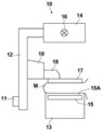
以下、図面を参照して本開示の実施形態について説明する。図1は本開示の実施形態による画像処理装置を適用した放射線画像撮影装置の概略構成図、図2は放射線画像撮影装置を図1の矢印A方向から見た図である。放射線画像撮影装置1は、乳房のトモシンセシス撮影を行って断層画像を生成するために、複数の線源位置から被写体である乳房Mを撮影して、複数の放射線画像、すなわち複数の投影画像を取得するマンモグラフィ撮影装置である。図1に示すように放射線画像撮影装置1は、撮影部10、撮影部10に接続されたコンピュータ2、並びにコンピュータ2に接続された表示部3および入力部4を備えている。
撮影部10は、不図示の基台に対して回転軸11により連結されたアーム部12を備えている。アーム部12の一方の端部には撮影台13が、その他方の端部には撮影台13と対向するように放射線照射部14が取り付けられている。アーム部12は、放射線照射部14が取り付けられた端部のみを回転することが可能に構成されており、これにより、撮影台13を固定して放射線照射部14のみを回転することが可能となっている。なお、アーム部12の回転は、コンピュータ2により制御される。
撮影台13の内部には、フラットパネルディテクタ等の放射線検出器15が備えられている。放射線検出器15は放射線の検出面15Aを有する。また、撮影台13の内部には、放射線検出器15から読み出された電荷信号を電圧信号に変換するチャージアンプ、チャージアンプから出力された電圧信号をサンプリングする相関2重サンプリング回路、および電圧信号をデジタル信号に変換するAD(Analog Digital)変換部等が設けられた回路基板等も設置されている。なお、放射線検出器15が検出部に対応する。また、本実施形態においては、検出部として放射線検出器15を用いているが、放射線を検出して画像に変換することができれば、放射線検出器15に限定されるものではない。
放射線検出器15は、放射線画像の記録および読み出しを繰り返して行うことができるものであり、X線等の放射線を直接電荷に変換する、いわゆる直接型の放射線検出器を用いてもよいし、放射線を一旦可視光に変換し、その可視光を電荷信号に変換する、いわゆる間接型の放射線検出器を用いるようにしてもよい。また、放射線画像信号の読出方式としては、TFT(Thin Film Transistor)スイッチをオンおよびオフすることによって放射線画像信号が読み出される、いわゆるTFT読出方式のもの、または読取光を照射することによって放射線画像信号が読み出される、いわゆる光読出方式のものを用いることが望ましいが、これに限らずその他のものを用いるようにしてもよい。
放射線照射部14の内部には、放射線源16が収納されている。放射線源16は放射線としてX線を出射するものであり、放射線源16から放射線を照射するタイミングおよび放射線源16における放射線発生条件、すなわちターゲットおよびフィルタの材質の選択、管電圧並びに照射時間等は、コンピュータ2により制御される。
また、アーム部12には、撮影台13の上方に配置されて乳房Mを押さえつけて圧迫する圧迫板17、圧迫板17を支持する支持部18、および支持部18を図1および図2の上下方向に移動させる移動機構19が設けられている。なお、圧迫板17と撮影台13との間隔、すなわち圧迫厚はコンピュータ2に入力される。
表示部3は、CRT(Cathode Ray Tube)または液晶モニタ等の表示装置であり、後述するように取得された投影画像、断層画像および合成2次元画像の他、操作に必要なメッセージ等を表示する。なお、表示部3は音声を出力するスピーカを内蔵するものであってもよい。
入力部4はキーボード、マウスまたはタッチパネル方式等の入力装置からなり、操作者による放射線画像撮影装置1の操作を受け付ける。また、トモシンセシス撮影を行うために必要な、撮影条件等の各種情報の入力および情報の修正の指示も受け付ける。本実施形態においては、操作者が入力部4から入力した情報に従って、放射線画像撮影装置1の各部が動作する。
コンピュータ2には、本実施形態による画像処理プログラムがインストールされている。本実施形態においては、コンピュータ2は、操作者が直接操作するワークステーションあるいはパーソナルコンピュータでもよいし、それらとネットワークを介して接続されたサーバコンピュータでもよい。画像処理プログラムは、DVD(Digital Versatile Disc)、CD-ROM(Compact Disc Read Only Memory)等の記録媒体に記録されて配布され、その記録媒体からコンピュータにインストールされる。もしくは、ネットワークに接続されたサーバコンピュータの記憶装置、あるいはネットワークストレージに、外部からアクセス可能な状態で記憶され、要求に応じてコンピュータにダウンロードされ、インストールされる。
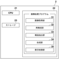
図3はコンピュータ2に本実施形態による画像処理プログラムをインストールすることにより実現される画像処理装置の概略構成を示す図である。図3に示すように、画像処理装置は、標準的なコンピュータの構成として、CPU(Central Processing Unit)21、メモリ22およびストレージ23を備えている。
ストレージ23は、ハードディスクドライブまたはSSD(Solid State Drive)等のストレージデバイスからなり、放射線画像撮影装置1の各部を駆動するためのプログラムおよび画像処理プログラムを含む各種情報が記憶されている。また、トモシンセシス撮影により取得された投影画像、後述するように生成された断層画像および合成2次元画像も記憶される。
メモリ22には、各種処理をCPU21に実行させるために、ストレージ23に記憶されたプログラム等が一時的に記憶される。画像処理プログラムは、CPU21に実行させる処理として、放射線画像撮影装置1にトモシンセシス撮影を行わせて、複数の線源位置のそれぞれに対応する乳房Mの複数の投影画像を取得する画像取得処理、複数の投影画像を再構成することにより、被写体である乳房Mの複数の断層面のそれぞれにおける断層画像を生成する再構成処理、複数の断層画像のそれぞれから特定構造を抽出する構造抽出処理、複数の断層画像のそれぞれにおける特定構造の画素の重みを、特定構造以外の画素の重みよりも大きくして、複数の断層画像から合成2次元画像を生成する合成処理、並びに合成2次元画像等を表示部3に表示する表示制御処理を規定する。
そして、CPU21が画像処理プログラムに従いこれらの処理を実行することで、コンピュータ2は、画像取得部31、再構成部32、構造抽出部33、合成部34、および表示制御部35として機能する。
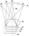
画像取得部31は、画像取得処理を行うに際し、アーム部12を回転軸11の周りに回転させることにより放射線源16を移動させ、放射線源16の移動による複数の線源位置において、トモシンセシス撮影用の予め定められた撮影条件により被写体である乳房Mに放射線を照射し、乳房Mを透過した放射線を放射線検出器15により検出して、複数の線源位置における複数の投影画像Gi(i=1~n、nは線源位置の数であり、例えばn=15)を取得する。
図4は投影画像Giの取得を説明するための図である。図4に示すように、放射線源16をS1、S2、・・・、Snの各線源位置に移動し、各線源位置において放射線源16を駆動して乳房Mに放射線を照射し、乳房Mを透過したX線を放射線検出器15により検出することにより、各線源位置S1~Snに対応して、投影画像G1、G2、・・・、Gnが取得される。なお、各線源位置S1~Snにおいては、同一の線量の放射線が乳房Mに照射される。取得された複数の投影画像Giはストレージ23に保存される。また、画像処理プログラムとは別個のプログラムにより複数の投影画像Giを取得してストレージ23または外部保存装置に保存するようにしてもよい。この場合、画像取得部31は、ストレージ23または外部保存装置に保存された複数の投影画像Giを、再構成処理等のためにストレージ23または外部保存装置から読み出すものとなる。
なお、図4において、線源位置Scは、放射線源16から出射された放射線の光軸X0が放射線検出器15の検出面15Aと直交する線源位置である。線源位置Scを基準線源位置Scと称するものとする。
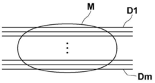
再構成部32は、複数の投影画像Giを再構成することにより、乳房Mの所望とする断層面を強調した断層画像を生成する。具体的には、再構成部32は、単純逆投影法あるいはフィルタ逆投影法等の周知の逆投影法等を用いて複数の投影画像Giを再構成して、図5に示すように、乳房Mの複数の断層面のそれぞれにおける複数の断層画像Dj(j=1~m)を生成する。この際、乳房Mを含む3次元空間における3次元の座標位置が設定され、設定された3次元の座標位置に対して、複数の投影画像Giの対応する画素位置の画素値が再構成されて、その座標位置の画素値が算出される。
構造抽出部33は、複数の断層画像Djから特定構造を抽出する。本実施形態においては、乳房Mに含まれるスピキュラおよび腫瘤を特定構造として抽出する。図6は特定構造の抽出を説明するための図である。ここでは、複数の断層画像Djのうちの1つの断層画像Dkからの特定構造の検出について説明する。図6に示すように、断層画像Dkには、断層画像Dkを取得した乳房Mの断層面におけるスピキュラおよび腫瘤が特定構造K1~K3として含まれる。なお、特定構造は、腫瘤の周囲に線状構造であるスピキュラを含むものとなっている。
構造抽出部33は、公知のコンピュータ支援画像診断(CAD: Computer Aided Diagnosis、以下CADと称する)のアルゴリズムを用いて、断層画像Dkから特定構造を抽出する。CADによるアルゴリズムにおいては、断層画像Djにおける画素が特定構造であることを表す確率が導出され、その確率が予め定められたしきい値以上の場合に、その画素が特定構造として検出される。特定構造の抽出はCADを用いるものに限定されない。特定構造を抽出するためのフィルタによるフィルタリング処理等によって、断層画像Dkから特定構造を抽出するものであってもよい。
合成部34は、複数の断層画像Djを用いて、基準線源位置Scから乳房Mに放射線を照射して撮影した単純2次元画像に相当する擬似的な2次元画像である合成2次元画像CG0を生成する。本実施形態においては、合成部34は、図7に示すように、複数の断層画像Djを積層した状態で、基準線源位置Scからの放射線検出器15へ向かう視点方向、すなわち図4に示す光軸X0に沿って、各断層画像Djにおいて対応する画素の画素値を重み付け加算する加算法により、合成2次元画像CG0を生成する。なお、合成2次元画像CG0の生成は、加算法に限定されるものではなく、公知の技術を適用することができる。加算法においては、重み付け加算する際の各画素に対する重みは、基本的には断層画像Djの数をmとした場合、1/mに設定されて合成2次元画像CG0が生成される。一方、本実施形態においては、複数の断層画像Djのそれぞれにおける特定構造の画素の重みが、特定構造以外の画素の重みよりも大きくされて、合成2次元画像CG0が生成される。
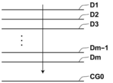
図8は本実施形態における重みの設定を説明するための図である。なお、図8においては説明のために10枚の断層画像D1~D10が生成され、特定構造K1が断層画像D2~D4に亘って含まれ、特定構造K2が断層画像D3~D6に亘って含まれ、特定構造K3が断層画像D8に含まれているものとする。なお、特定構造K1~K3は、図8においては説明のために厚さを持たせているが、実際には厚さはないものである。また、断層画像D2~D4のそれぞれに含まれる特定構造K1を、それぞれ特定構造K1-2,K1-3,K1-4とする。また、断層画像D3~D6のそれぞれに含まれる特定構造K2を、特定構造K2-3,K2-4,K2-5,K2-6とする。
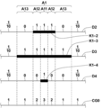
図8に示す特定構造K1は、3つの断層画像D2~D4に亘って含まれている。また、断層画像D3に含まれる特定構造K1-3のサイズが最も大きい。合成部34は、特定構造K1を含まない、断層画像D1,D5~D10において、特定構造K1に対応する対応画素の重みを、対応画素以外の画素の重みよりも小さくする。具体的には、図8に示す特定構造K1に対応する断層画像D1,D5~D10上の対応領域A1内の画素である対応画素の重みを、対応領域A1以外の領域の画素の重みよりも小さくする。本実施形態においては、断層画像D1,D5~D10上の対応領域A1内の対応画素の重みを0に設定する。また、断層画像D2において、特定構造K1-2の領域は対応領域A1よりも小さい。このため、合成部34は、断層画像D2の対応領域A1内における特定構造K1-2以外の領域の画素の重みを0に設定する。また、断層画像D4において、特定構造K1-4の領域は対応領域A1よりも小さい。このため、合成部34は、断層画像D4の対応領域A1内における特定構造K1-4以外の領域の画素の重みについても0に設定する。なお、重みの設定の処理については後述する。
また、図8に示す特定構造K2は、4つの断層画像D3~D6に亘って含まれている。また、断層画像D5に含まれる特定構造K2-5のサイズが最も大きい。合成部34は、特定構造K2を含まない、断層画像D1,D2,D7~D10において、特定構造K2に対応する対応画素の重みを、対応画素以外の画素の重みよりも小さくする。具体的には、図8に示す特定構造K2に対応する断層画像D1,D2,D7~D10上の対応領域A2内の画素である対応画素の重みを0に設定する。また、断層画像D3において、特定構造K2-3の領域は対応領域A2よりも小さい。このため、合成部34は、断層画像D3の対応領域A2内における特定構造K2-3以外の領域の画素の重みを0に設定する。また、断層画像D4において、特定構造K2-4の領域は対応領域A2よりも小さい。このため、合成部34は、断層画像D4の対応領域A2内における特定構造K2-4以外の領域の画素の重みを0に設定する。また、断層画像D6において、特定構造K2-6の領域は対応領域A2よりも小さい。このため、合成部34は、断層画像D6の対応領域A2内における特定構造K2-6以外の領域の画素の重みを0に設定する。
また、図8に示す特定構造K3は、1つの断層画像D8にのみ含まれている。合成部34は、特定構造K3を含まない、断層画像D1~7,D9,D10において、特定構造K3に対応する対応画素の重みを、対応画素以外の重みよりも小さくする。すなわち、図8に示す特定構造K3に対応する断層画像D1~7,D9,D10上の対応領域A3内の対応画素の重みを0に設定する。
一方、合成部34は、複数の断層画像Djのそれぞれにおける特定構造K1~K3の画素については、重みを1に設定する。これにより、合成2次元画像CG0における特定構造の画素の重みの合計値は、対応する画素に含まれる特定構造の画素の数となる。すなわち、合成2次元画像CG0における特定構造の画素値は、断層画像Djのそれぞれにおける特定構造の画素値の加算値となる。
図9は特定構造に対する重みの設定を説明するための図である。なお、ここでは、特定構造K1に対する重みの設定について説明するが、特定構造K2,K3についても同様に重みを設定すればよい。図9に示すように、合成部34は、断層画像D2~D4において特定構造K1の領域内の画素については、重みを1に設定する。ここで、断層画像D1,D5~D10においては、対応領域A1の画素の重みは0である。このため、合成2次元画像CG0上においては、特定構造K1に対応する対応領域A1内の画素のうち、3つの特定構造K1-2,K1-3.K1-4のすべてが重なる領域A11の画素については。重みの合計値は3となる。
また、合成2次元画像CG0上においては、対応領域A1内の画素のうち、断層画像D2,D3における2つの特定構造K1-2、K1-3のみが重なる領域A12の画素については、重みの合計値は2となる。
また、合成2次元画像CG0上においては、対応領域A1内の画素のうち、断層画像D3における特定構造K1-3が、他の断層画像D2,D4の特定構造K1-2,K1-4とは重ならない領域A13の画素については、重みの合計値は1となる。
なお、断層画像D2~D4の対応領域A1以外の領域において、他の断層画像D1,D5~D10に含まれるいずれの特定構造とも重ならない領域の画素については、断層画像の数が10である。このため、後述するノイズ画素を考慮しなければ、合成部34はこの領域の画素の重みを1/10に設定する。このため、合成2次元画像CG0上においては、いずれの特定構造とも重ならない領域の画素については、重みの合計値は1となる。
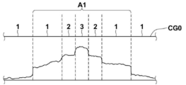
本実施形態においては、合成部34が上記のように重みを設定することにより、それぞれの断層画像Djに含まれる特定構造の画素の重みが、特定構造以外の画素の重みよりも大きくなる。ここで、特定構造の画素値は、特定構造以外の構造の画素値よりも大きい。このため、上記のように設定した重みにより生成される合成2次元画像CG0において、対応領域A10内の画素の画素値は、図10に示すように、他の領域よりも大きい値を有するものとなる。
さらに、本実施形態においては、合成部34は、各断層画像Djにおいて、特定構造の領域および特定構造に対応する対応領域以外の領域(以下、他の領域とする)において、ノイズ成分の割合が高い等、ノイズの影響が大きい画素(以下、ノイズ画素とする)については、合成2次元画像CG0の生成に際して、ノイズ画素の重み付けを低くするか、またはノイズ画素を除外する。なお、ノイズ画素の除外はノイズ画素の重みを0とすることと等価である。本実施形態においては、ノイズ画素に対する重みを0に設定するものとする。
ここで、断層画像Djにおいて、特定構造の画素は特定構造に応じて信号が大きくなるが、特定構造以外の画素は、定常的に発生しているノイズの影響が信号に表れるものの、比較的信号が小さい傾向がある。そこで、本実施形態では、合成部34は、複数の断層画像Djの他の領域について、合成2次元画像CG0を生成する際に加算する全画素の画素値の平均値を導出し、各々の画素値から平均値を除算した値の絶対値が予め定められた閾値Th以下となる画素について、ノイズ画素であるとみなし、ノイズ画素に対する重みを0に設定する。なお、閾値Thは、重畳するノイズの大きさ等に応じて、予め実験やシミュレーション等により定めておけばよい。
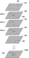
上記のように合成部34が重みを設定することにより、断層画像Djにおける特定構造を含む領域については、以下のように合成2次元画像CG0が生成される。図11は合成2次元画像の生成を説明するための図である。なお、図11においては、説明のために5枚の断層画像D1~D5からの合成2次元画像CG0の生成について説明する。図11に示すように断層画像D1~D5のうちの断層画像D2~D4に、それぞれ同一の特定構造を表す特定構造K4-2,K4-3,K4-4が含まれているものとする。特定構造K4-2,K4-3,K4-4は、腫瘤の周囲に線状構造であるスピキュラが存在している。また、断層画像D1,D2,D5にはそれぞれノイズN1,N2,N5が含まれている。
上記のように、特定構造K4-2,K4-3,K4-4の画素の重みは、特定構造K4-2,K4-3,K4-4以外の領域の画素の重みよりも大きくされている。とくに、特定構造K4-2,K4-3,K4-4については、重みがそれぞれ1に設定されている。また、断層画像D1,D5における特定構造K4-2,K4-3,K4-4に対応する対応領域内の画素の重みは0とされている。このため、合成2次元画像CG0における特定構造K4の画素の信号値は、断層画像D2~D4に含まれる特定構造K4-2,K4-3,K4-4の信号値のみの加算値となる。このため、合成2次元画像CG0においては、特定構造がそれ以外の領域に埋もれてしまうことがなくなる。
一方、断層画像D1~D5における特定構造K4-2,K4-3,K4-4および特定構造K4-2,K4-3,K4-4に対応する対応領域以外の他の領域の画素については、重みは1/5とされている。さらに、ノイズ画素については、合成に際して、重みが0とされている。このため、合成2次元画像CG0における特定構造K4以外の他の領域については、各断層画像D1~D5における特定構造以外の領域の画素と、実質的に同一の信号値を有し、かつノイズが除去されたものとなる。
なお、各断層画像Djの他の領域において、ノイズ画素が含まれる画素については、加算に際しての重みは断層画像の数からノイズ画素の数を減算した値に基づいて設定される。すなわち、m枚の断層画像を加算して合成2次元画像CG0を生成するに際し、合成2次元画像CG0上のある画素に対応する断層画像Djにd個のノイズ画素が存在する場合、その画素についての重みは1/mではなく、1/(m-d)となる。
なお、上述したように各断層画像Djにおける特定構造の領域の重みを1に設定すると、合成2次元画像CG0上における特定構造の画素値が、合成2次元画像CG0が取り得る画素値の最大値を超える場合がある。例えば、図9において、特定構造K1-2,K1-3,K1-4のすべてが重なる領域A11の画素については、重みの合計値は3となる。この場合において、合成2次元画像CG0が取り得る画素値の最大値が1024、特定構造K1-2,K1-3.K1-4のそれぞれの画素値が512であるとすると、合成2次元画像CG0における画素値は1536となり、合成2次元画像CG0が取り得る画素値の最大値が1024よりも大きくなる。その結果、その画素は、画素値が飽和した状態となる。このため、合成部34は、合成2次元画像CG0上における特定構造の画素値が、合成2次元画像CG0が取り得る画素値の最大値よりも大きくなる場合、合成2次元画像CG0における特定構造の領域内の画素の画素値を、合成2次元画像CG0が取り得る画素値の最大値により正規化する。
例えば、合成2次元画像CG0における画素値は1536となり、その値が特定構造内の画素値の最大値となる場合、画素値である1536が1024となるように、特定構造内の画素値を正規化する。この場合、特定構造内のすべての画素の画素値を、1024/1536倍となるように正規化する。これにより、合成2次元画像CG0に含まれる特定構造における画素値の飽和を防止することができる。
次いで、本実施形態において行われる処理について説明する。図12は、本実施形態において行われる処理を示すフローチャートである。操作者による処理開始の指示を入力部4が受け付けるとトモシンセシス撮影が行われて、画像取得部31が複数の投影画像Giを取得する(ステップST1)。次いで、再構成部32が、複数の投影画像Giを再構成することにより、乳房Mの複数の断層面における複数の断層画像Djを生成する(ステップST2)。なお、断層画像の枚数はmとする。さらに、構造抽出部33が、複数の断層画像Djのそれぞれから特定構造を抽出する(ステップST3)。次いで、合成部34が、複数の断層画像Djの各画素に対する合成2次元画像CG0の生成に際しての重みを設定する(重み設定処理;ステップST4)。
図13および図14は重み設定処理のフローチャートである。重み設定処理において、合成部34は、重みを設定した断層画像の数を管理するための変数kを0とし(k=0;ステップST11)、変数kに1を加算する(ステップST12)。そして、合成部34は、k枚目の断層画像における注目画素が、特定構造の画素であるか否かを判定する(ステップST13)。ステップST13が肯定されると、合成部34は、注目画素の重みを1に設定し(ステップST14)、ステップST21に進む。
一方、ステップST13が否定されると、合成部34は、k枚目の断層画像以外の他の断層画像において、注目画素に対応する対応画素に特定構造の画素があるか否かを判定する(ステップST15)。ステップST15が肯定されると、合成部34は、注目画素の重みを0に設定し(ステップST16)、ステップST21に進む。ステップST15が否定されると、合成部34は、注目画素がノイズ画素であるか否を判定する(ステップST17)。ステップST17が肯定されると、合成部34は注目画素の重みを0に設定し(ステップST18)、ステップST21に進む。ステップST17が否定されると、合成部34は、k枚目の断層画像以外の他の断層画像において、注目画素に対応する対応画素がノイズ画素である断層画像の数dをカウントし(ステップST19)、注目画素の重みを1/(m-d)に設定し(ステップST20)、ステップST21に進む。
ステップST21においては、合成部34は、k枚目の断層画像についてすべての画素の重みを設定したか否かを判定する。ステップST21が否定されると、注目画素を次の画素に変更し(ステップST22)、ステップST13に戻り、ステップST13以降の処理を繰り返す。ステップST21が肯定されると、合成部34は、変数kが、断層画像の枚数mと等しいか(k=m)否かを判定する(ステップST23)。変数kと枚数mとが等しくない場合、すなわち、注目画素に対応する重みの設定を行っていない断層画像が残っている場合、ステップST23が否定され、ステップST12に戻り、ステップST12以降の処理が繰り返される。ステップST23が肯定されると、重み設定処理を終了する。
図12に戻り、合成部34は、設定した重みを用いて複数の断層画像Dkから合成2次元画像CG0を生成する(ステップST5)。この際、必要があれば、上述したように、合成2次元画像CG0上において特定構造の画素の画素値が、合成2次元画像CG0の画素値の最大値により正規化される。そして、表示制御部35が、合成2次元画像CG0を表示部3に表示し(ステップST6)、処理を終了する。
このように、本実施形態においては、乳房Mの断層面を表す複数の断層画像Djのそれぞれから特定構造を抽出し、複数の断層画像Djのそれぞれにおける特定構造の画素の重みを、特定構造以外の画素の重みよりも大きくして、複数の断層画像Djから合成2次元画像CG0を生成するようにした。このため、合成2次元画像CG0においては、特定構造が特定構造以外の領域に埋もれてしまうことがなくなる。したがって、本実施形態によれば、合成2次元画像CG0において、特定構造を見やすくすることができる。
ところで、単純撮影により取得した乳房の単純2次元画像においては、スピキュラおよび腫瘤等の構造は高輝度(白く)となり、それ以外の脂肪は低輝度(黒く)なる。しかしながら、米国特許第8983156号明細書および米国特許出願公開第2014/0327702号明細書に記載された手法においては、合成2次元画像CG0を生成する際に、断層画像における対応する画素位置の信号値が平均等されるため、合成2次元画像CG0に含まれる脂肪の領域が、単純2次元画像と比較して白っぽくなってしまう。このため、合成2次元画像CG0の質感が単純2次元画像の質感と異なるものとなってしまう。また、米国特許第10140715号明細書に記載された手法では、スピキュラのような線状構造の上下の断層画像に含まれる正常な乳腺等のエッジが検出されるため、合成2次元画像CG0においては、乳腺等のエッジとスピキュラとが重なって、スピキュラが見えにくくなる。また、米国特許第10140715号明細書に記載された手法では、検出された乳腺等のエッジが重なって、スピキュラのように見える構造が合成2次元画像CG0に現れてしまう場合もある。
本実施形態においては、複数の断層画像Djのそれぞれにおいて、他の断層画像に含まれる特定構造に対応する対応画素の重みを、対応画素以外の画素の重みよりも小さくする、好ましくは0としている。これにより、合成2次元画像CG0に含まれる特定構造について、その特定構造が含まれる断層画像以外の断層画像における、特定構造以外の画素、例えば乳腺等のエッジ等の影響を少なくすることができる。したがって、合成2次元画像CG0を単純2次元画像と同様の質感を有するものとすることができる。また、合成2次元画像CG0において、特定構造が特定構造以外の構造と重なってしまい、特定構造が見えにくくなることを防止することができる。また、特定構造のように見える特定構造とは異なる構造が、合成2次元画像CG0に現れてしまうことを防止することができる。
なお、上記実施形態においては、複数の断層画像をトモシンセシス撮影により取得している。トモシンセシス撮影は、撮影装置の機械的な誤差、および複数の線源位置のそれぞれにおける撮影の時間差に起因する被写体の体動等の影響により、再構成された断層画像がぼけてしまうという問題もある。このように断層画像がぼけてしまうと、乳癌の早期発見に有用な、微小な石灰化等の病変を発見することが困難となる。
このため、図15に示す他の実施形態による画像処理装置に示すように、トモシンセシス撮影により取得された複数の投影画像間における、体動等に起因する位置ずれを補正するための位置ずれ補正部36を設けるようにしてもよい。位置ずれ補正部36による位置ずれ補正は、例えば特開2016-064119号公報に記載された手法等の任意の手法を用いることができる。特開2016-064119号公報に記載された手法は、複数の投影画像Giの位置が一致するように、複数の投影画像Gi間の位置ずれを補正する手法である。具体的には、SIFT(Scale-Invariant Feature Transform)あるいはSURF(Speeded Up Robust Features)等のアルゴリズムを用いて、各投影画像Giに含まれる、エッジ、エッジの交点およびエッジの角部等の特徴点を検出し、検出した特徴点を一致させるように、各投影画像Giを変換することにより、体動等に起因する位置ずれを補正する手法である。
このように、位置ずれ補正を行ってから再構成を行って断層画像を生成することにより、断層画像において、乳房Mに含まれる微小な石灰化が消えてしまうことがなくなる。したがって、合成2次元画像CG0において、異常部位を余すことなく表現することができる。
また、上記実施形態においては、合成部は、合成2次元画像CG0を生成するに際して、特定構造の境界にスムージング処理を行ってもよい。スムージング処理とは、特定構造の境界付近の画素値を滑らかに変化させて、境界に接する背景の画素値と一致させる処理を意味する。具体的には、合成2次元画像CG0を生成する際に、特定構造の境界付近の重みを変化させることにより、スムージング処理を行う。この際の重みは、構造抽出部33が特定構造を検出した際の確率に基づいて設定すればよい。
ここで、構造抽出部33が出力した確率の分布を図16に示す。図16に示すように、構造抽出部33が出力した確率は、特定構造の周囲ほど小さい値となり、しきい値Th1以上となる確率の領域が特定構造として検出される。このため、合成部34は、特定構造の確率に対応させて、図17に示すように特定構造に対する重みをその周囲の画素ほど1から徐々に小さくなって1/mとなるように設定する。これにより、図18に示すように、周囲との境界が不自然に明確な画素値を有する特定構造が、図19に示すように、周囲との境界が滑らかに変化する画素値を有するものとなる。これにより、合成2次元画像CG0においては、特定構造の境界が特定構造の画素値が隣接する背景の画素値に徐々に近づくようになる。したがって、特定構造とその背景とがより自然に交わる合成2次元画像CG0を生成することができる。
なお、スムージング処理は、上記のように導出される重みを用いる手法に限定されるものではない。合成2次元画像CG0に含まれる特定構造の境界を、ローパスフィルタによってフィルタリングすることにより、スムージング処理を行うようにしてもよい。
また、上記実施形態においては、複数の断層画像Djにおいて、特定構造および他の断層画像の特定構造に対応する対応領域の画素については、ノイズ画素であるか否かを判定しているが、これに限定されるものではない。ノイズ画素であるか否かを判定することなく、断層画像の枚数mにより1を除算した値1/mを重みとして設定してもよい。
また、上記実施形態においては、断層画像Djのそれぞれにおいて、特定構造の重みを1としているがこれに限定されるものではない。複数の断層画像Dj間において、対応する画素に含まれる特定構造の画素の数をcとしたとき、特定構造の画素の重みを1/cに設定してもよい。この場合、合成部34は、特定構造の画素については、合成2次元画像CG0の生成に際して、重みの合計値が1となるように重みを設定することとなる。
また、上記実施形態においては、合成部34が合成2次元画像を生成する方法とし加算法を適用したが、上述したように、公知の他の技術を適用することができる。例えば、各断層画像の対応する画素における最小値を用いる、いわゆる最小経路法を適用してもよい。
また、上記実施形態における放射線は、とくに限定されるものではなく、X線の他、α線またはγ線等を適用することができる。
また、上記実施形態において、例えば、画像取得部31、再構成部32、構造抽出部33、合成部34、表示制御部35および位置ずれ補正部36といった各種の処理を実行する処理部(Processing Unit)のハードウェア的な構造としては、次に示す各種のプロセッサ(Processor)を用いることができる。上記各種のプロセッサには、上述したように、ソフトウェア(プログラム)を実行して各種の処理部として機能する汎用的なプロセッサであるCPUに加えて、FPGA(Field Programmable Gate Array)等の製造後に回路構成を変更可能なプロセッサであるプログラマブルロジックデバイス(Programmable Logic Device :PLD)、ASIC(Application Specific Integrated Circuit)等の特定の処理を実行させるために専用に設計された回路構成を有するプロセッサである専用電気回路等が含まれる。
1つの処理部は、これらの各種のプロセッサのうちの1つで構成されてもよいし、同種または異種の2つ以上のプロセッサの組み合わせ(例えば、複数のFPGAの組み合わせまたはCPUとFPGAとの組み合わせ)で構成されてもよい。また、複数の処理部を1つのプロセッサで構成してもよい。
複数の処理部を1つのプロセッサで構成する例としては、第1に、クライアントおよびサーバ等のコンピュータに代表されるように、1つ以上のCPUとソフトウェアとの組み合わせで1つのプロセッサを構成し、このプロセッサが複数の処理部として機能する形態がある。第2に、システムオンチップ(System On Chip:SoC)等に代表されるように、複数の処理部を含むシステム全体の機能を1つのIC(Integrated Circuit)チップで実現するプロセッサを使用する形態がある。このように、各種の処理部は、ハードウェア的な構造として、上記各種のプロセッサの1つ以上を用いて構成される。
さらに、これらの各種のプロセッサのハードウェア的な構造としては、より具体的には、半導体素子等の回路素子を組み合わせた電気回路(Circuitry)を用いることができる。
1 放射線画像撮影装置
2 コンピュータ
3 表示部
4 入力部
10 撮影部
15 放射線検出器
16 放射線源
17 圧迫板
21 CPU
22 メモリ
23 ストレージ
31 画像取得部
32 再構成部
33 構造抽出部
34 合成部
35 表示制御部
36 位置ずれ補正部
A1~A3 対応領域
CG0 合成2次元画像
Dj(j=1~m)、Dk 断層画像
Gi(i=1~n) 投影画像
K1~K4 特定構造
M 乳房
Si(i=1~n) 線源位置
Sc 基準線源位置
X0 光軸
2 コンピュータ
3 表示部
4 入力部
10 撮影部
15 放射線検出器
16 放射線源
17 圧迫板
21 CPU
22 メモリ
23 ストレージ
31 画像取得部
32 再構成部
33 構造抽出部
34 合成部
35 表示制御部
36 位置ずれ補正部
A1~A3 対応領域
CG0 合成2次元画像
Dj(j=1~m)、Dk 断層画像
Gi(i=1~n) 投影画像
K1~K4 特定構造
M 乳房
Si(i=1~n) 線源位置
Sc 基準線源位置
X0 光軸
Claims (13)
- 被写体の複数の断層面を表す複数の断層画像のそれぞれから、特定構造を抽出する構造抽出部と、
前記複数の断層画像のそれぞれにおける前記特定構造の画素の重みを、該特定構造以外の画素の重みよりも大きくして、前記複数の断層画像から合成2次元画像を生成する合成部とを備えた画像処理装置。 - 前記合成部は、前記複数の断層画像のそれぞれにおける前記特定構造以外の画素において、他の断層画像に含まれる前記特定構造に対応する対応画素の重みを、該対応画素以外の画素の重みよりも小さくする請求項1に記載の画像処理装置。
- 前記合成部は、前記対応画素の重みを0に設定する請求項2に記載の画像処理装置。
- 前記合成部は、前記複数の断層画像のそれぞれにおける前記特定構造の重みを1に設定する請求項1から3のいずれか1項に記載の画像処理装置。
- 前記合成部は、前記合成2次元画像上における前記特定構造の画素値を、前記合成2次元画像が取り得る画素値の最大値に基づいて正規化する請求項4に記載の画像処理装置。
- 前記合成部は、前記複数の断層画像の対応する画素の画素値を、前記重みにより重みづけ加算することにより、前記合成2次元画像を生成する請求項1から5のいずれか1項に記載の画像処理装置。
- 放射線源を検出部の検出面に対して相対的に移動させ、前記放射線源の移動による複数の線源位置において前記被写体に放射線を照射するトモシンセシス撮影を撮影装置に行わせることにより生成された、前記複数の線源位置のそれぞれに対応する複数の投影画像を取得する画像取得部と、
前記複数の投影画像を再構成することにより、前記複数の断層画像を生成する再構成部とをさらに備えた請求項1から6のいずれか1項に記載の画像処理装置。 - 前記複数の投影画像間の位置ずれを補正する位置ずれ補正部をさらに備え、
前記再構成部は、前記位置ずれが補正された前記複数の投影画像を再構成することにより、前記複数の断層画像を生成する請求項7に記載の画像処理装置。 - 前記合成部は、前記合成2次元画像における前記特定構造の境界にスムージング処理を行う請求項1から8のいずれか1項に記載の画像処理装置。
- 前記合成部は、前記複数の断層画像のそれぞれにおいて、前記特定構造および他の断層画像に含まれる前記特定構造の画素に対応する対応画素以外の画素については、前記特定構造よりもノイズの影響が大きいノイズ画素の重み付けを低くするか、または前記ノイズ画素を除外して、前記合成2次元画像を生成する請求項1から9のいずれか1項に記載の画像処理装置。
- 前記被写体は乳房であり、前記特定構造がスピキュラおよび腫瘤である請求項1から10のいずれか1項に記載の画像処理装置。
- 被写体の複数の断層面を表す複数の断層画像のそれぞれから、特定構造を抽出し、
前記複数の断層画像のそれぞれにおける前記特定構造の画素の重みを、該特定構造以外の画素の重みよりも大きくして、前記複数の断層画像から合成2次元画像を生成する画像処理方法。 - 被写体の複数の断層面を表す複数の断層画像のそれぞれから、特定構造を抽出する手順と、
前記複数の断層画像のそれぞれにおける前記特定構造の画素の重みを、該特定構造以外の画素の重みよりも大きくして、前記複数の断層画像から合成2次元画像を生成する手順とをコンピュータに実行させる画像処理プログラム。
Priority Applications (3)
| Application Number | Priority Date | Filing Date | Title |
|---|---|---|---|
| JP2021511086A JP7187678B2 (ja) | 2019-03-29 | 2019-10-23 | 画像処理装置、方法およびプログラム |
| EP19922862.8A EP3949862A4 (en) | 2019-03-29 | 2019-10-23 | IMAGE PROCESSING DEVICE, METHOD AND PROGRAM |
| US17/464,723 US20210393226A1 (en) | 2019-03-29 | 2021-09-02 | Image processing apparatus, image processing method, and image processing program |
Applications Claiming Priority (2)
| Application Number | Priority Date | Filing Date | Title |
|---|---|---|---|
| JP2019067746 | 2019-03-29 | ||
| JP2019-067746 | 2019-03-29 |
Related Child Applications (1)
| Application Number | Title | Priority Date | Filing Date |
|---|---|---|---|
| US17/464,723 Continuation US20210393226A1 (en) | 2019-03-29 | 2021-09-02 | Image processing apparatus, image processing method, and image processing program |
Publications (1)
| Publication Number | Publication Date |
|---|---|
| WO2020202612A1 true WO2020202612A1 (ja) | 2020-10-08 |
Family
ID=72667877
Family Applications (1)
| Application Number | Title | Priority Date | Filing Date |
|---|---|---|---|
| PCT/JP2019/041480 Ceased WO2020202612A1 (ja) | 2019-03-29 | 2019-10-23 | 画像処理装置、方法およびプログラム |
Country Status (4)
| Country | Link |
|---|---|
| US (1) | US20210393226A1 (ja) |
| EP (1) | EP3949862A4 (ja) |
| JP (1) | JP7187678B2 (ja) |
| WO (1) | WO2020202612A1 (ja) |
Cited By (2)
| Publication number | Priority date | Publication date | Assignee | Title |
|---|---|---|---|---|
| EP4066745A1 (en) * | 2021-03-29 | 2022-10-05 | FUJI-FILM Corporation | Image processing device, image processing method, and image processing program |
| EP4066744A1 (en) * | 2021-03-29 | 2022-10-05 | FUJI-FILM Corporation | Image processing device, image processing method, and image processing program |
Citations (8)
| Publication number | Priority date | Publication date | Assignee | Title |
|---|---|---|---|---|
| JPS5952251B2 (ja) | 1978-02-21 | 1984-12-19 | 川崎重工業株式会社 | 大型構造物沈下構築方法 |
| US20140327702A1 (en) | 2005-11-10 | 2014-11-06 | Hologic, Inc | System and method for generating a 2d image using mammography and/or tomosynthesis image data |
| US8983156B2 (en) | 2012-11-23 | 2015-03-17 | Icad, Inc. | System and method for improving workflow efficiences in reading tomosynthesis medical image data |
| JP2015205019A (ja) * | 2014-04-21 | 2015-11-19 | ジーイー・メディカル・システムズ・グローバル・テクノロジー・カンパニー・エルエルシー | 画像処理装置、放射線断層撮影装置及びプログラム |
| US20160078645A1 (en) * | 2014-09-12 | 2016-03-17 | Siemens Aktiengesellschaft | Method and apparatus for projection image generation from tomographic images |
| JP2016064119A (ja) | 2014-09-19 | 2016-04-28 | 富士フイルム株式会社 | 断層画像生成装置、方法およびプログラム |
| JP2017143943A (ja) * | 2016-02-16 | 2017-08-24 | 富士フイルム株式会社 | 放射線画像処理装置、方法およびプログラム |
| US10140715B2 (en) | 2014-07-31 | 2018-11-27 | Siemens Aktiengesellschaft | Method and system for computing digital tomosynthesis images |
Family Cites Families (6)
| Publication number | Priority date | Publication date | Assignee | Title |
|---|---|---|---|---|
| JP4575909B2 (ja) * | 2006-11-22 | 2010-11-04 | ジーイー・メディカル・システムズ・グローバル・テクノロジー・カンパニー・エルエルシー | X線断層撮影装置 |
| US8634622B2 (en) * | 2008-10-16 | 2014-01-21 | Icad, Inc. | Computer-aided detection of regions of interest in tomographic breast imagery |
| US8885926B2 (en) * | 2009-04-15 | 2014-11-11 | Massachusetts Institute Of Technology | Image and data segmentation |
| US9836872B2 (en) * | 2013-06-28 | 2017-12-05 | Koninklijke Philips N.V. | Methods for generation of edge=preserving synthetic mammograms from tomosynthesis data |
| US10692273B2 (en) * | 2017-06-01 | 2020-06-23 | Siemens Healthcare Gmbh | In-context photorealistic 3D visualization for surgical decision support |
| JP6945462B2 (ja) * | 2018-01-17 | 2021-10-06 | 富士フイルム株式会社 | 画像処理装置、画像処理方法、及び画像処理プログラム |
-
2019
- 2019-10-23 WO PCT/JP2019/041480 patent/WO2020202612A1/ja not_active Ceased
- 2019-10-23 JP JP2021511086A patent/JP7187678B2/ja active Active
- 2019-10-23 EP EP19922862.8A patent/EP3949862A4/en active Pending
-
2021
- 2021-09-02 US US17/464,723 patent/US20210393226A1/en not_active Abandoned
Patent Citations (8)
| Publication number | Priority date | Publication date | Assignee | Title |
|---|---|---|---|---|
| JPS5952251B2 (ja) | 1978-02-21 | 1984-12-19 | 川崎重工業株式会社 | 大型構造物沈下構築方法 |
| US20140327702A1 (en) | 2005-11-10 | 2014-11-06 | Hologic, Inc | System and method for generating a 2d image using mammography and/or tomosynthesis image data |
| US8983156B2 (en) | 2012-11-23 | 2015-03-17 | Icad, Inc. | System and method for improving workflow efficiences in reading tomosynthesis medical image data |
| JP2015205019A (ja) * | 2014-04-21 | 2015-11-19 | ジーイー・メディカル・システムズ・グローバル・テクノロジー・カンパニー・エルエルシー | 画像処理装置、放射線断層撮影装置及びプログラム |
| US10140715B2 (en) | 2014-07-31 | 2018-11-27 | Siemens Aktiengesellschaft | Method and system for computing digital tomosynthesis images |
| US20160078645A1 (en) * | 2014-09-12 | 2016-03-17 | Siemens Aktiengesellschaft | Method and apparatus for projection image generation from tomographic images |
| JP2016064119A (ja) | 2014-09-19 | 2016-04-28 | 富士フイルム株式会社 | 断層画像生成装置、方法およびプログラム |
| JP2017143943A (ja) * | 2016-02-16 | 2017-08-24 | 富士フイルム株式会社 | 放射線画像処理装置、方法およびプログラム |
Non-Patent Citations (1)
| Title |
|---|
| See also references of EP3949862A4 |
Cited By (8)
| Publication number | Priority date | Publication date | Assignee | Title |
|---|---|---|---|---|
| EP4066745A1 (en) * | 2021-03-29 | 2022-10-05 | FUJI-FILM Corporation | Image processing device, image processing method, and image processing program |
| EP4066744A1 (en) * | 2021-03-29 | 2022-10-05 | FUJI-FILM Corporation | Image processing device, image processing method, and image processing program |
| JP2022153115A (ja) * | 2021-03-29 | 2022-10-12 | 富士フイルム株式会社 | 画像処理装置、画像処理方法、及び画像処理プログラム |
| JP2022153114A (ja) * | 2021-03-29 | 2022-10-12 | 富士フイルム株式会社 | 画像処理装置、画像処理方法、及び画像処理プログラム |
| JP7542477B2 (ja) | 2021-03-29 | 2024-08-30 | 富士フイルム株式会社 | 画像処理装置、画像処理方法、及び画像処理プログラム |
| US12112479B2 (en) | 2021-03-29 | 2024-10-08 | Fujifilm Corporation | Image processing device, image processing method, and image processing program |
| JP7607489B2 (ja) | 2021-03-29 | 2024-12-27 | 富士フイルム株式会社 | 画像処理装置、画像処理方法、及び画像処理プログラム |
| US12536649B2 (en) | 2021-03-29 | 2026-01-27 | Fujifilm Corporation | Image processing device, image processing method, and image processing program for facilitating image diagnosis using mammography apparatus to generate composite two-dimensional tomographic image using selected tomographic image slices corresponding to detected spicula regions |
Also Published As
| Publication number | Publication date |
|---|---|
| EP3949862A4 (en) | 2022-05-25 |
| JPWO2020202612A1 (ja) | 2020-10-08 |
| EP3949862A1 (en) | 2022-02-09 |
| US20210393226A1 (en) | 2021-12-23 |
| JP7187678B2 (ja) | 2022-12-12 |
Similar Documents
| Publication | Publication Date | Title |
|---|---|---|
| US8913713B2 (en) | Radiographic image generation device and method | |
| JP7275363B2 (ja) | 位置ずれ量導出装置、方法およびプログラム | |
| JP7017492B2 (ja) | 断層画像生成装置、方法およびプログラム | |
| JP7084291B2 (ja) | トモシンセシス撮影支援装置、方法およびプログラム | |
| JP7203705B2 (ja) | 画像処理装置、方法およびプログラム、並びに画像表示装置、方法およびプログラム | |
| JP7513697B2 (ja) | 画像生成装置およびプログラム、学習装置およびプログラム、並びに画像処理装置およびプログラム | |
| EP3590431B1 (en) | Image display device, image display method, and image display program | |
| JP7187678B2 (ja) | 画像処理装置、方法およびプログラム | |
| JP7451748B2 (ja) | 画像処理装置、画像処理装置の作動方法、画像処理装置の作動プログラム | |
| US11517280B2 (en) | Image processing apparatus, method, and program | |
| JP7113790B2 (ja) | 画像処理装置、方法およびプログラム | |
| JP7446410B2 (ja) | 画像処理装置、方法およびプログラム | |
| JP7607489B2 (ja) | 画像処理装置、画像処理方法、及び画像処理プログラム | |
| JP7542477B2 (ja) | 画像処理装置、画像処理方法、及び画像処理プログラム | |
| JP7430814B2 (ja) | 画像処理装置、画像処理方法、及び画像処理プログラム | |
| JP7208874B2 (ja) | 撮影制御装置、方法およびプログラム | |
| JP2025040874A (ja) | 画像処理装置、放射線画像撮影システム及びプログラム | |
| JP2025138515A (ja) | 画像処理装置、放射線画像撮影システム及びプログラム | |
| JP2025051943A (ja) | 画像処理装置、放射線画像撮影システム及びプログラム | |
| WO2022018943A1 (ja) | 画像処理装置、方法およびプログラム | |
| WO2023171073A1 (ja) | 画像処理装置、方法およびプログラム | |
| WO2021186956A1 (ja) | 画像処理装置、方法およびプログラム |
Legal Events
| Date | Code | Title | Description |
|---|---|---|---|
| 121 | Ep: the epo has been informed by wipo that ep was designated in this application |
Ref document number: 19922862 Country of ref document: EP Kind code of ref document: A1 |
|
| ENP | Entry into the national phase |
Ref document number: 2021511086 Country of ref document: JP Kind code of ref document: A |
|
| NENP | Non-entry into the national phase |
Ref country code: DE |
|
| ENP | Entry into the national phase |
Ref document number: 2019922862 Country of ref document: EP Effective date: 20211029 |