WO2020202828A1 - 通信制御装置、通信装置、及び通信制御方法 - Google Patents
通信制御装置、通信装置、及び通信制御方法 Download PDFInfo
- Publication number
- WO2020202828A1 WO2020202828A1 PCT/JP2020/005653 JP2020005653W WO2020202828A1 WO 2020202828 A1 WO2020202828 A1 WO 2020202828A1 JP 2020005653 W JP2020005653 W JP 2020005653W WO 2020202828 A1 WO2020202828 A1 WO 2020202828A1
- Authority
- WO
- WIPO (PCT)
- Prior art keywords
- communication
- communication device
- interference
- base station
- wireless system
- Prior art date
- Legal status (The legal status is an assumption and is not a legal conclusion. Google has not performed a legal analysis and makes no representation as to the accuracy of the status listed.)
- Ceased
Links
Images















Classifications
-
- H—ELECTRICITY
- H04—ELECTRIC COMMUNICATION TECHNIQUE
- H04W—WIRELESS COMMUNICATION NETWORKS
- H04W72/00—Local resource management
- H04W72/50—Allocation or scheduling criteria for wireless resources
- H04W72/54—Allocation or scheduling criteria for wireless resources based on quality criteria
- H04W72/541—Allocation or scheduling criteria for wireless resources based on quality criteria using the level of interference
-
- H—ELECTRICITY
- H04—ELECTRIC COMMUNICATION TECHNIQUE
- H04W—WIRELESS COMMUNICATION NETWORKS
- H04W16/00—Network planning, e.g. coverage or traffic planning tools; Network deployment, e.g. resource partitioning or cells structures
- H04W16/14—Spectrum sharing arrangements between different networks
-
- H—ELECTRICITY
- H04—ELECTRIC COMMUNICATION TECHNIQUE
- H04W—WIRELESS COMMUNICATION NETWORKS
- H04W72/00—Local resource management
- H04W72/04—Wireless resource allocation
- H04W72/044—Wireless resource allocation based on the type of the allocated resource
-
- H—ELECTRICITY
- H04—ELECTRIC COMMUNICATION TECHNIQUE
- H04W—WIRELESS COMMUNICATION NETWORKS
- H04W16/00—Network planning, e.g. coverage or traffic planning tools; Network deployment, e.g. resource partitioning or cells structures
- H04W16/18—Network planning tools
-
- H—ELECTRICITY
- H04—ELECTRIC COMMUNICATION TECHNIQUE
- H04W—WIRELESS COMMUNICATION NETWORKS
- H04W16/00—Network planning, e.g. coverage or traffic planning tools; Network deployment, e.g. resource partitioning or cells structures
- H04W16/24—Cell structures
- H04W16/28—Cell structures using beam steering
-
- H—ELECTRICITY
- H04—ELECTRIC COMMUNICATION TECHNIQUE
- H04W—WIRELESS COMMUNICATION NETWORKS
- H04W24/00—Supervisory, monitoring or testing arrangements
- H04W24/02—Arrangements for optimising operational condition
Definitions
- the present invention relates to a communication control device, a communication device, and a communication control method.
- radio resources wireless resources
- wireless devices wireless devices
- cognitive radio technology radio resources are generated by using the temporal and spatial free radio waves (White Space) of existing wireless systems.
- this disclosure proposes a communication control device, a communication device, and a communication control method that can realize efficient use of radio wave resources.
- the communication control device of one form according to the present disclosure is based on the position of the communication device of the second wireless system that secondarily uses the frequency resource primarily used by the first wireless system.
- a communication device of the first wireless system to be calculated for interference caused by the communication device of the second wireless system based on a protection target range set above the communication device of the second wireless system.
- a selection unit for selection is provided.
- a plurality of components having substantially the same functional configuration may be distinguished by adding different numbers after the same reference numerals.
- a plurality of configurations having substantially the same functional configuration are distinguished as necessary, such as the aerial communication device 10A 1 and 10A 2 .
- a plurality of configurations having substantially the same functional configuration are distinguished as necessary, such as terrestrial communication terminals 10B 1 and 10B 2 .
- the communication control device as necessary 40 1, and as 40 2 having substantially the same function and structure.
- the terminal device 20 When it is not necessary to distinguish between the terminal apparatus 20 1, and 20 2 are simply referred to as the terminal device 20.
- the base station devices 30 1 and 30 2 When it is not necessary to distinguish between the base station devices 30 1 and 30 2 , it is simply referred to as the base station device 30.
- the communication control apparatus 40 1, and in particular the 40 2 does not need to be distinguished, simply referred to as a communication control unit 40.
- radio resources are generated by utilizing the temporal and spatial free radio waves (White Space) of existing wireless systems (for example, dynamic frequency sharing (DSA: Dynamic Spectrum Access)).
- DSA Dynamic Spectrum Access
- CBRS CBRS
- CBRS CBRS
- Cognitive radio technology contributes not only to dynamic frequency sharing but also to improvement of frequency utilization efficiency by wireless systems.
- ETSI EN 303 387 and IEEE 802.119.1-2014 stipulate coexistence technology between wireless systems that use free radio waves.
- control of wireless system to realize frequency sharing >
- the NRA sets an allowable interference reference value for the primary system, and the interference generated by sharing is lower than the allowable interference reference value for the wireless system (secondary system) of the secondary user (secondary user). You are asked to do that.
- a communication control device controls communication of a secondary system so as not to cause fatal interference to the primary system.
- the communication control device is a device that manages the communication of the communication device.
- the communication control device is a device (system) for managing radio wave resources (for example, frequency) such as GLDB (Geo-location Database) and SAS (Spectrum Access System).
- the communication control device corresponds to the communication control device 40 described later.
- the communication control device 40 will be described in detail later.
- the primary system is, for example, a system (for example, an existing system) that preferentially uses radio waves in a predetermined frequency band over other systems such as a secondary system.
- the secondary system is, for example, a system that secondarily uses (for example, dynamic frequency sharing) radio waves in the frequency band used by the primary system.
- Each of the primary system and the secondary system may be composed of a plurality of communication devices, or may be composed of one communication device.
- the communication control device has 1 so that the cumulative interference of one or more communication devices constituting the secondary system with the primary system does not exceed the interference allowance (also referred to as interference margin) of the primary system.
- the interference allowance is distributed to a plurality of communication devices.
- the allowable interference amount may be a predetermined amount of interference by the operator of the primary system, a public organization that manages radio waves, or the like.
- the term "interference margin" refers to the amount of interference allowed.
- the accumulation of interference may be referred to as cumulative interference power.
- FIG. 1 is an explanatory diagram showing an example of allocating an interference margin to each communication device constituting the secondary system.
- the communication system 1 is the primary system and the communication system 2 is the secondary system.
- Communication system 1 comprises a communication device 10 1 and the like.
- the communication system 2 comprises a base station apparatus 30 1, 30 2, 30 3, and the like.
- the communication system 1 includes only one communication device 10, but the communication system 1 may have a plurality of communication devices 10.
- the communication system 2 includes three base station devices 30, but the number of base station devices 30 included in the communication system 2 may be less than or more than three.
- the wireless communication device included in the communication system 2 does not necessarily have to be a base station device.
- only one primary system communication system 1 in the example of FIG. 1 and one secondary system (communication system 2 in the example of FIG. 1) are shown, but the primary system and the secondary system are shown. There may be more than one of each.
- the communication device 10 1 and the base station devices 30 1 , 30 2 , and 30 3 can transmit and receive radio waves, respectively.
- the amount of interference the communication device 101 permits are I the accept.
- the amount of interference given to the predetermined protection point of the base station apparatus 30 1, 30 2, 30 3 the communication system 1 (primary system) are the interfering amount I 1, I 2, I 3.
- the protection point is an interference calculation reference point for protection of the communication system 1.
- the communication control device includes a plurality of base station devices 30 so that the accumulation of interference to a predetermined protection point of the communication system 1 (received interference amount I 1 + I 2 + I 3 shown in FIG. 1) does not exceed the interference margin I accident.
- the interference margin I assist is allocated to.
- the communication control device allocates the interference margin I- accept to each base station device 30 so that the interference amounts I 1 , I 2 , and I 3 are I- accept / 3, respectively.
- the communication control device allocates the interference margin I- accept to each base station device 30 so that the interference amounts I 1 , I 2 , and I 3 are each I- accept / 3 or less.
- the method of allocating the interference margin is not limited to this example.
- the communication control device calculates the maximum transmission power (hereinafter referred to as the maximum allowable transmission power) allowed for each base station device 30 based on the distributed interference amount (hereinafter referred to as the distributed interference amount). For example, the communication control device calculates the maximum allowable transmission power of each base station device 30 by back-calculating from the distributed interference amount based on the propagation loss, the antenna gain, and the like. Then, the communication control device notifies each base station device 30 of the calculated maximum allowable transmission power information.
- the distributed interference amount the distributed interference amount
- a method of centrally managing communication parameters such as frequency band, transmission power, transmission filter, and wireless access method that should be used by the communication system may be adopted by the database device.
- Such databases are adopted in the form of GLDB and SAS in TV White Spaces in the United Kingdom and the United States, and CBRS in the United States.
- secondary system, Secondary System, etc. a low priority
- high priority primary system, Primary System, Incumbent System, etc.
- Patent Document 1 in order to avoid or reduce fatal interference of the primary system with the communication device by the database device, the position information (latitude, longitude, altitude, etc.) of the communication device of the primary system and the secondary system A mechanism for determining whether or not the secondary system may use the frequency preferentially assigned to the primary system for secondary use in terms of location and space by using the position information of the communication device and the expected radio wave propagation characteristics. It is disclosed.
- Patent Document 1 only the propriety of secondary frequency use (OK / NG) of the secondary system is determined, and the finer particle size is not determined. This means that by actually adjusting the communication parameters of the secondary system, the operation of the secondary system may not be permitted even in a place / space where the frequency sharing between the secondary system and the primary system can be realized. .. In other words, it may hinder the improvement of utilization efficiency of finite frequency resources.
- the communication control device selects from the communication device of the secondary system which aerial communication device of the primary system should be considered as the protection target of interference.
- the "interference" referred to here includes, for example, interference from a single communication device or cumulative interference from a plurality of communication devices (Aggregated Interference).
- Interference with the aerial communication device includes, for example, interference with a communication link from the terrestrial communication device (terrestrial terminal device, terrestrial fixed communication device) of the primary system to the aerial communication device, or communication between the aerial communication devices of the secondary system. Interference with links, etc.
- the selection of the aerial communication device of the primary system is performed as one of the purposes of controlling the interference from the communication device of the secondary system to the aerial communication device of the primary system to a predetermined level or less.
- FIG. 2 is an explanatory diagram showing a hierarchical structure in CBRS.
- each of the users in the frequency band falls into one of three groups. This group is called "tier".
- Each of the three groups has a defined hierarchical structure consisting of an existing layer (Incumbent Tier), a priority access layer (Priority Access Tier), and a general authorized access layer (General Authorized Access Tier).
- the priority access layer (Priority Access Tier) is located above the general authorized access layer (General Authorized Access Tier)
- the existing layer Incumbent Tier
- the existing layer is located above the priority access layer.
- the system located in the existing layer becomes the primary system
- the system located in the general authorization access layer and the priority access layer becomes the secondary system.
- the existing layer is a group consisting of existing users in the shared frequency band.
- CBRS the Department of Defense (DOD), fixed satellite operators, and wireless broadband licensees exempt from new conditions (GWBL: Grandfathered Wireless Broadband Licensee) are defined as existing users.
- DOD Department of Defense
- GWBL Grandfathered Wireless Broadband Licensee
- the “Incumbent Tier” is not required to avoid or suppress interference with the "Priority Access Tier” and "GAA (General Authorized Access) Tier", which have lower priorities.
- “Incumbent Tier” is protected from interference by "Priority Access Tier” and "GAA Tier”. That is, the user of "Incumbent Tier" can use the frequency band without considering the existence of other groups.
- the Priority Access Tier is a group of licensed users called PAL (Priority Access License). Interference avoidance or suppression to "Incumbent Tier” having a higher priority than “Priority Access Tier” is required, but interference avoidance or suppression to "GAA Tier” having a lower priority is not required. Further, the "Priority Access Tier” is not protected from the interference by the "Incumbent Tier” having a higher priority, but is protected from the interference by the "GAA Tier” having a lower priority.
- the general authorization access layer (GAA Tier) is a group consisting of all other users who do not belong to the above “Incumbent Tier” and “Priority Access Tier”. It is required to avoid or suppress interference with "Incumbent Tier” and “Priority Access Tier” which have higher priority. Also, the "GAA Tier” is not protected from interference by the "Incumbent Tier”, which has a higher priority, and the "Priority Access Tier”. That is, "GAA Tier” is a “tier” that is legally required to use opportunistic frequencies.
- CBRS is generally called a 3 Tier structure, but may have a 2 Tier structure.
- 2-tier structure such as LSA (Licensed Shared Access) and TVWS (TV band White Space).
- LSA the same structure as the combination of the above "Incumbent Tier” and “Priority Access Tier” is adopted.
- TVWS a structure equivalent to the combination of the above “Incumbent Tier” and “GAA Tier” is adopted.
- 4 or more tiers may exist. Specifically, for example, the intermediate layer corresponding to "Priority Access Tier” may be further prioritized. Further, for example, "GAA Tier” may be prioritized in the same manner.
- FIG. 3 is an explanatory diagram showing a CBRS band.
- the primary system is a military radar system (Military Radar System), an existing wireless system (Grand fathered Wireless System), or a fixed satellite service (space to earth) (Fixed Satellite Service (space-to-earth)).
- the military radar system is typically a carrier-based radar.
- the secondary system will be a wireless network system consisting of base stations and terminals called CBSD (Citizens Broadband Radio Service Device) and EUD (End User Device).
- CBSD Cas Broadband Radio Service Device
- EUD End User Device
- the secondary system has a higher priority, and a priority access license (PAL: Priority Access License) that allows the shared bandwidth to be licensed and a general authorized access (GAA: General Authorized Access) that is equivalent to no license required are defined.
- PAL Priority Access License
- GAA General Authorized Access
- Layer 1 (Tier 1) shown in FIG. 3 corresponds to the existing layer shown in FIG.
- layer 2 (Tier 2) shown in FIG. 3 corresponds to the priority access layer shown in FIG.
- the layer 3 (Tier 3) shown in FIG. 3 corresponds to the general authorization access layer shown in FIG.
- the primary system (communication system 1) of the present embodiment is not limited to the example shown in FIG.
- Another type of wireless system may be the primary system (communication system 1).
- another wireless system may be used as the primary system depending on the country / region / frequency band to which it is applied.
- the primary system may be a television broadcasting system such as a DVB-T (Digital Video Broadcasting-Terrestrial) system.
- the primary system may be a wireless system called FS (Fixed System).
- the frequency may be shared in other frequency bands.
- LSA and TVWS TV band White Space
- the primary system may be a cellular communication system such as LTE (Long Term Evolution) or NR (New Radio).
- the primary system may be an aeronautical radio system such as ARNS (Aeronautical Radio Navigation Service).
- the primary system is not limited to the above wireless system, and may be another type of wireless system.
- the free radio wave (White Space) used by the communication system 2 is not limited to the radio wave of Federal use band (3.55-3.70 GHz).
- the communication system 2 may use radio waves in a frequency band different from the Federal use band (3.55-3.70 GHz) as free radio waves.
- the primary system (communication system 1) is a television broadcasting system
- the communication system 2 may be a system that uses the TV white space as an empty radio wave.
- the TV white space refers to a frequency band that is not used by the television broadcasting system among the frequency channels assigned to the television broadcasting system (primary system). At this time, the TV white space may be a channel that is not used depending on the region.
- the relationship between the communication system 1 and the communication system 2 is not limited to the frequency sharing relationship in which the communication system 1 is the primary system and the communication system 2 is the secondary system.
- the relationship between the communication system 1 and the communication system 2 may be a network coexistence relationship between the same or different wireless systems using the same frequency.
- the existing system that uses the target band is called the primary system
- the system of the secondary user is called the secondary system.
- these (primary system, secondary) System) may be replaced with a system of another term.
- the macro cell in HetNet may be the primary system
- the small cell or relay station may be the secondary system.
- the base station may be the primary system
- the Relay UE or Vehicle UE that realizes D2D or V2X existing in the coverage may be the secondary system.
- the base station is not limited to the fixed type, and may be a portable type / mobile type.
- the communication control device provided by the present invention may be provided in a base station, a relay station, a Relay UE, or the like.
- frequency may be replaced by another term.
- frequency has the terms “resource”, “resource block”, “resource element”, “channel”, “component carrier”, “carrier”, “subcarrier”, and similar meanings. It may be replaced by the term it has.
- the frequency is a kind of radio wave resource.
- Radio resource can also be paraphrased as "frequency resource”.
- the communication system 100 includes a communication system 1 and a communication system 2.
- Communication system 1 (first wireless system) is a wireless communication system that wirelessly communicates by using (primary use) a predetermined frequency band.
- the communication system 2 (second wireless system) is a wireless communication system that secondarily uses the frequency band used by the communication system 1 for wireless communication.
- the communication system 2 is a wireless communication system that dynamically shares the free radio waves of the communication system 1.
- the communication system 2 uses a predetermined radio access technology to provide a wireless service to a user or a device owned by the user.
- primary use means that a certain wireless system (for example, communication system 1) uses a frequency resource dedicated to the wireless system or a frequency resource preferentially allocated.
- secondary use means that a certain wireless system (for example, communication system 2) selects a frequency resource exclusively allocated to another wireless system (communication system 1) or a frequency resource preferentially allocated. It is to be used with a lower priority than the wireless system (communication system 1) of.
- the communication systems 1 and 2 may be cellular communication systems such as W-CDMA (Wideband Code Division Multiple Access), cdma2000 (Code Division Multiple Access 2000), LTE, and NR.
- LTE shall include LTE-A (LTE-Advanced), LTE-A Pro (LTE-Advanced Pro), and EUTRA (Evolved Universal Terrestrial Radio Access).
- NR shall include NRAT (New Radio Access Technology) and FEUTRA (Further EUTRA).
- NR is the next generation (fifth generation) wireless access technology (RAT) of LTE.
- RAT wireless access technology
- LTE Long Term Evolution
- NR is a wireless access technology that can support various use cases including eMBB (Enhanced Mobile Broadband), mMTC (Massive Machine Type Communications) and URLLC (Ultra-Reliable and Low Latency Communications).
- eMBB Enhanced Mobile Broadband
- mMTC Massive Machine Type Communications
- URLLC Ultra-Reliable and Low Latency Communications
- communication systems 1 and 2 are not limited to cellular communication systems.
- the communication system 2 may be another wireless communication system such as a wireless LAN (Local Area Network) system, a television broadcasting system, an aeronautical wireless system, or a space wireless communication system.
- the communication system 1 is the primary system and the communication system 2 is the secondary system. As described above, there may be a plurality of each of the communication system 1 and the communication system 2.
- the communication system 1 is composed of one communication device 10 (communication device 101 shown in FIG. 1 ), but as described above, it may be composed of a plurality of communication devices 10. Good.
- the configuration of the communication device 10 may be the same as or different from the configuration of the terminal device 20 or the base station device 30 described later.
- Communication system 100 typically comprises the following entities: Communication equipment (for example, base station equipment and proxy equipment) Terminal device Communication control device
- the entity that becomes the communication device is assumed to be the communication device 10, the base station device 30 and / or the proxy device 50, but the entity that becomes the communication device is not limited to these devices, and other entities. It may be a communication device (for example, a terminal device 20, a communication control device 40).
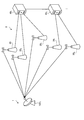
- FIG. 4 is a diagram showing a configuration example of the communication system 100 according to the embodiment of the present disclosure.
- the communication system 100 includes a communication system 1 and a communication system 2.
- the device in the figure can also be considered as a device in a logical sense. That is, a part of the device shown in the figure may be realized by a virtual machine (VM: Virtual Machine), a container (Container), a docker (Docker), etc., and they may be implemented on physically the same hardware.
- VM Virtual Machine
- Container Container
- Docker docker
- the communication system 1 includes aerial communication devices 10A 1 , 10A 2 , terrestrial terminal devices 10B 1 , 10B 2 , 10B 3 , and terrestrial fixed communication device 10C 1 .
- the aerial communication device 10A include a fixed satellite communication device, a mobile satellite communication device, and a drone communication device.
- the communication system 1 includes two aerial communication devices 10A, but the aerial communication device 10A included in the communication system 1 may be less than or more than two.
- the communication system 1 includes three terrestrial communication terminals 10B, but the number of terrestrial communication terminals 10B included in the communication system 1 may be less than or more than three. Further, in the example of FIG.
- the communication system 1 includes one terrestrial fixed communication device 10C, but the communication system 1 may include more than one terrestrial fixed communication device 10C.
- the communication system 1 may include more than one terrestrial fixed communication device 10C.
- each of the aerial communication device 10A 1 , 10A 2 , the terrestrial terminal device 10B 1 , 10B 2 , 10B 3 , and the terrestrial fixed communication device 10C 1 as one communication system 1.
- Examples of the communication system 2 include a terrestrial communication system (4G (LTE) or 5G (NR) cellular system, wireless LAN system, etc.). However, the communication system 2 may include an aerial communication device.
- the communication device (terminal device, base station device, access point device, etc.) of the communication system 2 is a direct or other communication device (for example, a communication device in the core network (Serving Gateway (S-GW), Packet Gateway (P-)). GW), Mobility Management Entity (MME), etc.), Communication control device (Management Entity, Geolocation Database (GLDB), Spectrum Access) via communication devices (server, cloud, edge, router, switch, etc.) in the Internet System (SAS), etc.) 40 is connected.
- S-GW Serving Gateway
- P- Packet Gateway
- MME Mobility Management Entity
- GLDB Geolocation Database
- SAS Internet System
- the terminal device 20 of the communication system 2 may be a device called CPE (Customer Premise Equipment) used for the wireless backhaul.
- CPE Customer Premise Equipment
- such a terminal device 20 may be treated as a base station device 30 (for example, at the time of interference calculation). That is, the CPE has the properties of both the terminal device 20 and the base station device 30.
- the communication system 2 includes a terminal device 20, a base station device 30, a communication control device 40, and a proxy device 50.
- the communication system 2 provides a wireless service to a user or a device owned by the user by operating in cooperation with each device (for example, a communication device such as a wireless communication device) constituting the communication system 2.
- the wireless communication device is a device having a wireless communication function, and in the example of FIG. 4, the terminal device 20 and the base station device 30 correspond to each other.
- the communication systems 1 and 2 provide a wireless service to a user or a device owned by the user by operating in cooperation with each device (for example, a communication device such as a wireless communication device) constituting the communication systems 1 and 2.
- a wireless communication device is a device having a wireless communication function.
- the aerial communication device 10A 1 , 10A 2 , the terrestrial terminal device 10B 1 , 10B 2 , 10B 3 , the terrestrial fixed communication device 10C 1 , the terminal device 20, and the base station device 30 correspond to the wireless communication device. ..
- the communication control device 40 and the proxy device 50 may have a wireless communication function.
- the communication control device 40 and the proxy device 50 can also be regarded as wireless communication devices.
- the wireless communication device may be simply referred to as a communication device.
- the communication device is not limited to the wireless communication device.
- a device that does not have a wireless communication function and can only perform wired communication can be regarded as a communication device.
- the concept of "communication device” includes not only a portable mobile device such as a mobile terminal (for example, a terminal device) but also a device installed on a structure or a mobile body.
- the structure or the moving body itself may be regarded as a communication device.
- the concept of a communication device includes not only a terminal device but also a base station device and a relay device.
- a communication device is a type of processing device and information processing device.
- the description of "communication device” appearing in the following description can be appropriately rephrased as “transmitting device” or “receiving device”.
- the concept of "communication” includes “broadcasting".
- the description of "communication device” can be appropriately rephrased as “broadcasting device”.
- the description of "communication device” may be appropriately rephrased as “transmitting device” or “receiving device”.
- the communication system 2 may include a plurality of terminal devices 20, a base station device 30, a communication control device 40, and a proxy device 50, respectively.
- the communication system 2 includes a terminal device 20 1, 20 2, 20 3, 20 4, etc. as a terminal device 20.
- the communication system 2 includes a base station apparatus 30 1, 30 2, 30 3, 30 4, 30 5 or the like as the base station apparatus 30.
- the communication system 2 includes only one communication control device 40, but the communication system 2 may have more than one communication control device 40.
- the wireless communication device may be referred to as a wireless system.
- the aerial communication device 10A 1 , 10A 2 , the terrestrial terminal device 10B 1 , 10B 2 , 10B 3 , and the terrestrial fixed communication device 10C 1 are each one wireless system.
- the base station apparatus 30 1 to 30 5, respectively, is one of a wireless system.
- the terminal devices 20 1 to 20 4, respectively, is one radio system.
- the one or more communication devices 10 included in the communication system 1 are referred to as the first radio system, but the communication system 1 itself is the first radio for each of the one or more communication devices 10 included in the communication system 1. It may be regarded as a system.
- one or a plurality of base station devices 30 included in the communication system 2 are referred to as the second wireless system, but the communication system 2 itself may be regarded as the second wireless system, and the communication system 2 may be regarded as the second wireless system.
- Each of the one or more terminal devices 20 provided may be regarded as a second wireless system. If the communication control device 40 and the proxy device 50 have a wireless communication function, each of the communication control device 40 or the proxy device 50 may be regarded as a second wireless system.
- the wireless system may be one system composed of a plurality of communication devices including at least one wireless communication device.
- a system composed of one or more aerial communication devices 10A and one or more terrestrial communication terminals 10B under the aerial communication device 10A, or one or more terrestrial fixed communication devices 10C is regarded as one wireless system.
- You may.
- a system composed of one or a plurality of base station devices 30 and one or a plurality of terminal devices 20 under the base station device 30 may be regarded as one wireless system.
- each of the communication system 1 and the communication system 2 may be referred to as a wireless communication system or simply a communication system.
- one system composed of a plurality of communication devices including one wireless communication device may be regarded as a first wireless system or a second wireless system.
- the system means a set of a plurality of components (devices, modules (parts), etc.). At this time, all the components constituting the system may or may not be in the same housing. For example, a plurality of devices housed in separate housings and connected via wired and / or wireless are one system. Further, one device in which a plurality of modules are housed in one housing is also one system.
- the terminal device 20 is a communication device having a communication function.
- the terminal device 20 is typically a communication device such as a smartphone.
- the terminal device 20 may be a user terminal such as a mobile phone, a smart device (smartphone or tablet), a wearable terminal, an IoT (Internet of Things) device, a PDA (Personal Digital Assistant), or a personal computer.
- the terminal device may be referred to as User Equipment, User Terminal, User Station, Mobile Terminal, Mobile Station, or the like.
- the terminal device 20 may be capable of side link communication with another terminal device 20.
- the terminal device 20 may be able to use an automatic retransmission technique such as HARQ (Hybrid ARQ (Automatic Repeat reQuest)) when performing side link communication.
- HARQ Hybrid ARQ (Automatic Repeat reQuest)
- the wireless communication (including side link communication) used by the terminal device 20 may be wireless communication using radio waves or wireless communication using infrared rays or visible light (optical radio). Good.
- the terminal device 20 may be a mobile device.
- the mobile device is a mobile wireless communication device.
- the terminal device 20 may be a wireless communication device installed on the mobile body or may be the mobile body itself.
- the terminal device 20 may be a vehicle (Vehicle) moving on the road such as an automobile, a bus, a truck, or a motorcycle, or a wireless communication device mounted on the vehicle.
- the moving body may be a mobile terminal, or may be a moving body that moves on land (ground in a narrow sense), in the ground, on the water, or in the water.
- the moving body may be a moving body that moves in the atmosphere such as a drone or a helicopter, or may be a moving body that moves outside the atmosphere such as an artificial satellite.
- the terminal device 20 may be connected to a plurality of base station devices or a plurality of cells at the same time to perform communication.
- a plurality of cells for example, pCell, sCell
- CA Carrier Aggregation
- DC Dual Connectivity
- MC multi-connectivity
- the terminal device 20 and the plurality of base station devices 30 can communicate with each other via the cells of different base station devices 30 by the coordinated multi-point transmission and reception (CoMP) technology.
- CoMP coordinated multi-point transmission and reception
- the terminal device 20 does not have to be used by a person.
- the terminal device 20 may be a sensor installed in a factory machine or a building, such as a so-called MTC (Machine Type Communication). Further, the terminal device 20 may be an M2M (Machine to Machine) device or an IoT (Internet of Things) device. Further, the terminal device 20 may be a device having a relay communication function, as typified by D2D (Device to Device) and V2X (Vehicle to everything). Further, the terminal device 20 may be a device called CPE (Client Premises Equipment) used in a wireless backhaul or the like. Further, the terminal device 20 may be a wireless communication device installed on the mobile body, or may be the mobile body itself.
- MTC Machine Type Communication
- M2M Machine to Machine
- IoT Internet of Things
- the terminal device 20 may be a device having a relay communication function, as typified by D2D (Device to Device) and V2X (
- the base station device 30 (second wireless system) is a wireless communication device that wirelessly communicates with the terminal device 20 or another communication device (another base station device 30, another proxy device 50).
- the base station device 30 is a type of communication device.
- the base station device 30 is, for example, a device corresponding to a radio base station (Base Station, Node B, eNB, gNB, etc.) or a radio access point (Access Point).
- the base station device 30 may be a wireless relay station.
- the base station device 30 may be a road base station device such as an RSU (Road Side Unit). Further, the base station device 30 may be an optical overhanging device called an RRH (Remote Radio Head).
- the base station of the wireless communication system may be referred to as a base station device.
- the wireless access technology used by the base station device 30 may be a cellular communication technology or a wireless LAN technology.
- the wireless access technology used by the base station apparatus 30 is not limited to these, and may be another wireless access technology.
- the base station device 30 does not necessarily have to be fixed, and may be installed in a moving object such as an automobile. Further, the base station device 30 does not necessarily have to exist on the ground, but exists in the air or in the air such as an aircraft, a drone, a helicopter, a satellite, or in the sea or in the sea such as a ship or a submarine.
- the object to be used may be provided with a communication device function. In such a case, the base station device 30 can perform wireless communication with another communication device fixedly installed.
- a base station device also referred to as a base station
- a base station includes not only a donor base station but also a relay base station (also referred to as a relay station or a relay station device).
- the concept of a base station also includes access points.
- the concept of a base station includes not only a structure having a function of a base station but also a device installed in the structure.
- the structure is, for example, a building such as an office building, a house, a steel tower, a station facility, an airport facility, a port facility, or a stadium.
- the concept of a structure includes not only buildings but also non-building structures such as tunnels, bridges, dams, fences, and iron pillars, and equipment such as cranes, gates, and wind turbines.
- the concept of structures includes not only structures on land (above ground in a narrow sense) or underground, but also structures on water such as piers and mega floats, and structures underwater such as ocean observation facilities.
- the base station device 30 may be a donor station or a relay station (relay station). Further, the base station device 30 may be a fixed station or a mobile station.
- a mobile station is a wireless communication device (for example, a base station device) configured to be mobile.
- the base station device 30 may be a device installed on the mobile body or may be the mobile body itself.
- a relay station device having mobility can be regarded as a base station device 30 as a mobile station.
- devices such as vehicles, drones, and smartphones that are originally mobile and equipped with the functions of the base station device (at least a part of the functions of the base station device) are also included in the base station device 30 as a mobile station. Applicable.
- the mobile body may be a mobile terminal such as a smartphone or a mobile phone.
- the moving body may be a moving body (for example, a vehicle such as a car, a bicycle, a bus, a truck, a motorcycle, a train, a linear motor car, etc.) that moves on land (ground in a narrow sense), or in the ground (for example, a vehicle).
- a moving body for example, a subway moving in a tunnel.
- the moving body may be a moving body moving on water (for example, a ship such as a passenger ship, a cargo ship, or a hovercraft), or a moving body moving underwater (for example, a submersible, a submarine, an unmanned submarine, etc.). Submersible).
- the moving body may be a moving body moving in the atmosphere (for example, an aircraft such as an airplane, an airship, or a drone), or a moving body moving outside the atmosphere (for example, an artificial satellite, a spaceship, or a space station).
- An artificial celestial body such as a spacecraft).
- a moving body that moves outside the atmosphere can be rephrased as a space moving body.
- the base station device 30 may be a ground base station device (ground station device) installed on the ground.
- the base station device 30 may be a base station device arranged on a structure on the ground, or may be a base station device installed on a mobile body moving on the ground.
- the base station device 30 may be an antenna installed in a structure such as a building and a signal processing device connected to the antenna.
- the base station device 30 may be a structure or a moving body itself. "Ground" is not only land (ground in a narrow sense) but also ground in a broad sense including underground, water, and water.
- the base station device 30 is not limited to the ground base station device.
- the base station device 30 may be a non-ground base station device (non-ground station device) capable of floating in the air or in space.
- the base station device 30 may be an aircraft station device or a satellite station device.
- the aircraft station device is a wireless communication device that can float in the atmosphere such as an aircraft.
- the aircraft station device may be a device mounted on an aircraft or the like, or may be an aircraft itself.
- the concept of an aircraft includes not only heavy aircraft such as airplanes and gliders, but also light aircraft such as balloons and airships.
- the concept of an aircraft includes not only heavy aircraft and light aircraft, but also rotary-wing aircraft such as helicopters and autogyros.
- the aircraft station device (or the aircraft on which the aircraft station device is mounted) may be an unmanned aerial vehicle such as a drone.
- unmanned aerial vehicle also includes unmanned aerial vehicles (UAS: Unmanned Aircraft Systems) and tethered unmanned aerial vehicles (tethered UAS).
- UAS Unmanned Aircraft Systems
- tethered UAS tethered unmanned aerial vehicles
- unmanned aerial vehicle includes a light unmanned aerial vehicle system (LTA: Lighter than Air UAS) and a heavy unmanned aerial vehicle system (HTA: Heavier than Air UAS).
- HAPs High Altitude UAS Platforms.
- the satellite station device is a wireless communication device that can float outside the atmosphere.
- the satellite station device may be a device mounted on a space mobile body such as an artificial satellite, or may be a space mobile body itself.
- the satellites that serve as satellite station equipment are low orbit (LEO: Low Earth Orbiting) satellites, medium orbit (MEO: Medium Earth Orbiting) satellites, geostationary (GEO: Geostationary Earth Orbiting) satellites, and high elliptical orbit (HEO: Highly Elliptical Orbiting). It may be any satellite.
- the satellite station device may be a device mounted on a low earth orbit satellite, a medium earth orbit satellite, a geostationary satellite, or a high elliptical orbit satellite.
- the base station device 30 may be a relay station device.
- the relay station device is, for example, an aviation station or an earth station.
- the relay station device can be regarded as a kind of the above-mentioned relay device.
- An aviation station is a radio station installed on the ground or on a mobile body moving on the ground to communicate with an aircraft station device.
- the earth station is a radio station located on the earth (including the air) in order to communicate with the satellite station device.
- the earth station may be a large earth station or a small earth station such as VSAT (Very Small Aperture Terminal).
- VSAT Very Small Aperture Terminal
- the earth station may be a VSAT controlled earth station (also referred to as a master station or a HUB station) or a VSAT earth station (also referred to as a slave station). Further, the earth station may be a radio station installed in a mobile body moving on the ground. For example, as an earth station mounted on a ship, an onboard earth station (ESV: Earth Stations on board Vessels) can be mentioned. In addition, the earth station may include an aircraft earth station installed on an aircraft (including a helicopter) and communicating with a satellite station. In addition, the earth station may include an aviation earth station which is installed in a mobile body moving on the ground and communicates with an aircraft earth station via a satellite station.
- the relay station device may be a portable mobile radio station that communicates with a satellite station or an aircraft station.
- the size of the coverage of the base station device 30 may also be from a large one such as a macro cell to a small one such as a pico cell. Of course, the size of the coverage of the base station device 30 may be extremely small, such as a femtocell. Further, when the base station apparatus 30 has a beamforming capability, a cell or a service area may be formed for each beam.
- the base station device 30 can be used, operated, and / or managed by various entities.
- the base station device 30 includes a mobile communication operator (MNO: Mobile Network Operator), a virtual mobile communication operator (MVNO: Mobile Virtual Network Operator), a virtual mobile communication enabler (MVNE: Mobile Virtual Network Enabler), Neutral Host Network (NHN: Neutral Host Network) operators, enterprises, educational institutions (school corporations, local government education committees, etc.), real estate (buildings, condominiums, etc.) managers, individuals, etc. can be assumed.
- MNO Mobile Network Operator
- MVNO Mobile Virtual Network Operator
- MVNE Virtual Network Enabler
- NHS Neutral Host Network
- N Neutral Host Network
- the subject of use, operation, and / or management of the base station device 30 is not limited to these.
- the base station device 30 may be installed and / or operated by one business operator, or may be installed and / or operated by an individual.
- the installation / operation entity of the base station device 30 is not limited to these.
- the base station device 30 may be jointly installed and operated by a plurality of businesses or a plurality of individuals.
- the base station device 30 may be a shared facility used by a plurality of businesses or a plurality of individuals. In this case, the installation and / or operation of the equipment may be carried out by a third party different from the user.
- the base station device 30 operated by the operator is typically connected to the Internet via a core network. Further, the base station apparatus 30 is operated and maintained by a function called OA & M (Operation, Administration & Maintenance).
- the communication system 2 may have, for example, a network manager that integrally controls the base station apparatus 30 in the network.
- the communication control device 40 is a device that manages the base station device 30.
- the communication control device 40 is a device that controls wireless communication of the base station device 30.
- the communication control device 40 is a device that determines communication parameters (also referred to as operation parameters) used by the base station device 30 and gives permission or instruction to the base station device 30.
- the communication control device 40 may be a network manager that integrally controls wireless devices in the network. Taking ETSI EN 303 387 and IEEE 802.19.1-2014 as an example, the communication control device 40 may be a control device such as a Spectram Manager / Spectrum Manager that controls radio wave interference between wireless devices. Further, for example, the RLSS (Registered Location Secure Server) defined in IEEE 802.11-2016 can also be the communication control device 40. Further, in a frequency sharing environment, a database (database server, device, system) such as GLDB (Geolocation database) or SAS (Spectrum Access System) can also be the communication control device 40.
- a database database server, device, system
- GLDB Global Database
- SAS Specific Access System
- the communication control device 40 may be a device that constitutes a core network.
- the core network CN is, for example, EPC (Evolved Packet Core) or 5GC (5G Core network).
- EPC Evolved Packet Core
- 5GC 5G Core network
- the communication control device 40 may be, for example, a device having a function as an MME (Mobility Management Entity).
- MME Mobility Management Entity
- the communication control device 40 may be, for example, a device having a function as an AMF (Access and Mobility Management Function).
- the communication control device 40 does not necessarily have to be a device that constitutes a core network.
- the communication control device 40 may be a device having a function as an RNC (Radio Network Controller).
- RNC Radio Network Controller
- the communication control device 40 may have a gateway function.
- the communication control device 40 may be a device having a function as an S-GW (Serving Gateway) or a P-GW (Packet Data Network Gateway).
- the communication control device 40 may be a device having a function as an UPF (User Plane Function).
- the communication control device 40 does not necessarily have to be a device that constitutes the core network. For example, assume that the core network is a W-CDMA or cdma2000 core network. At this time, the communication control device 40 may be a device that functions as an RNC (Radio Network Controller).
- RNC Radio Network Controller
- the control target of the communication control device 40 is the base station device 30, but the communication control device 40 may control the terminal device 20 under the control device 40. Further, the communication control device 40 may control a plurality of secondary systems. In this case, the communication system 2 can be regarded as a system including a plurality of secondary systems.
- FIG. 5 is a diagram showing a model in which the communication control device 40 is arranged in a distributed manner.
- the communication control device 40 1 and the communication control unit 40 2 a plurality of communication control device 40 to exchange information of the base station device 30 that manages one another, the required frequency allocation and interference Perform control calculations.
- the communication control device 40 may be a master-slave type device.
- FIG. 6 is a diagram showing a model (so-called master-slave type model) in which one communication control device centrally controls a plurality of communication control devices.
- the communication control device 40 3 are master communication control device
- communication control unit 40 4, 60 5 is the slave communications controller.
- the master communication control device can control a plurality of slave communication control devices and make a centralized decision.
- the master communication control device can transfer or destroy the decision-making authority to each slave communication control device for the purpose of load balancing (load balancing) or the like.
- the communication control device 40 can acquire necessary information from entities other than the terminal device 20, the base station device 30, and the proxy device 50 for its role.
- the communication control device 40 can acquire information necessary for protection, such as location information of the primary system, from a database (regular database) managed and operated by a national / regional radio wave administrative agency, for example.
- a database regular database
- An example of a regulatory database is the ULS (Universal Licensing System) operated by the Federal Communications Commission (US Federal Communications Commission).
- Other examples of information required for protection include, for example, Out-of-Band Emission (OOBE) Limit, Adjacent Channel Leakage Ratio (ACLR), Adjacent Channel Selectivity (Adjacent). Channel Selectivity), fading margin, and / or protection ratio (PR), etc. may be included. For these examples, it is legally desirable to use them when the numerical values are fixed.
- the communication control device 40 acquires radio wave sensing information from a radio wave sensing system installed and operated for the purpose of detecting radio waves in the primary system.
- the communication control device 40 can acquire radio wave detection information of the primary system from a radio wave sensing system such as an environmental sensing function (ESC: Environmental Sensing Capability) in the US CBRS.
- ESC Environmental Sensing Capability
- the communication control device 40 may acquire the radio wave detection information of the primary system from these.
- the proxy device 50 (proxy system) is a device that communicates with the communication control device 40 on behalf of (representatively) one or a plurality of communication devices (for example, the base station device 30).
- the proxy device 50 is also a type of communication device.
- the proxy device 50 may be a DP (Domain Proxy) defined in Non-Patent Document 2 or the like.
- the DP refers to an entity that communicates with SAS on behalf of each of a plurality of CBSDs or a network composed of a plurality of CBSDs.
- the proxy device 50 is not limited to the DP defined in Non-Patent Document 2 as long as it has a function of communicating with the communication control device 40 on behalf of (representative) one or a plurality of communication devices. ..
- the network manager that integrally controls the base station device 30 in the network may be regarded as the proxy device 50.
- the proxy system may be composed of one device or a plurality of devices.
- the communication between the proxy device 50 and the base station device 30 may be wired communication or wireless communication.
- the communication between the proxy device 50 and the communication control device 40 may be wired communication or wireless communication.
- the communication device represented (represented) by the proxy device 50 is not limited to the base station device 30, and may be, for example, the terminal device 20.
- one or more communication devices for example, one or more base station devices 30
- subordinate communication devices for example, subordinate base station devices 30.
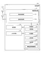
- FIG. 7 is a diagram showing a configuration example of the terminal device 20 according to the embodiment of the present disclosure.
- the terminal device 20 is a communication device that wirelessly communicates with the base station device 30 and / or the communication control device 40.
- the concept of a communication device includes not only a base station device and a proxy device but also a terminal device.
- a communication device (or wireless communication device) can be rephrased as a wireless system.
- the terminal device 20 includes a wireless communication unit 21, a storage unit 22, an input / output unit 23, and a control unit 24.
- the configuration shown in FIG. 7 is a functional configuration, and the hardware configuration may be different from this. Further, the functions of the terminal device 20 may be distributed and implemented in a plurality of physically separated configurations.
- the wireless communication unit 21 is a wireless communication interface that wirelessly communicates with other communication devices (for example, a base station device 30 and another terminal device 20).
- the wireless communication unit 21 operates according to the control of the control unit 24.
- the wireless communication unit 21 corresponds to one or a plurality of wireless access methods.
- the wireless communication unit 21 corresponds to both NR and LTE.
- the wireless communication unit 21 may support other wireless access methods such as W-CDMA and cdma2000.
- the wireless communication unit 21 includes a reception processing unit 211, a transmission processing unit 212, and an antenna 213.
- the wireless communication unit 21 may include a plurality of reception processing units 211, transmission processing units 212, and antennas 213, respectively.
- each unit of the wireless communication unit 21 may be individually configured for each wireless access method.
- the reception processing unit 211 and the transmission processing unit 212 may be individually configured by LTE and NR.
- the configurations of the reception processing unit 211 and the transmission processing unit 212 are the same as those of the reception processing unit 311 and the transmission processing unit 312 of the base station apparatus 30 described later.
- the storage unit 22 is a data readable / writable storage device such as a DRAM (Dynamic Random Access Memory), a SRAM (Static RAM), a flash memory, and a hard disk.
- the storage unit 22 functions as a storage means for the terminal device 20.
- the input / output unit 23 is a user interface for exchanging information with the user.
- the input / output unit 23 is an operation device for the user to perform various operations such as a keyboard, a mouse, operation keys, and a touch panel.
- the input / output unit 23 is a display device such as a liquid crystal display (Liquid Crystal Display) or an organic EL display (Organic Electroluminescence Display).
- the input / output unit 23 may be an audio device such as a speaker or a buzzer.
- the input / output unit 23 may be a lighting device such as an LED (Light Emitting Diode) lamp.
- the input / output unit 23 functions as an input / output means (input means, output means, operation means, or notification means) of the terminal device 20.
- the control unit 24 is a controller that controls each unit of the terminal device 20.
- the control unit 24 is realized by, for example, a processor such as a CPU (Central Processing Unit) or an MPU (Micro Processing Unit).
- the control unit 24 is realized by the processor executing various programs stored in the storage device inside the terminal device 20 with the RAM or the like as a work area.
- the control unit 24 may be realized by an integrated circuit such as an ASIC (Application Specific Integrated Circuit) or an FPGA (Field Programmable Gate Array).
- the CPU, MPU, ASIC, and FPGA can all be regarded as controllers.
- the control unit 34 may have each functional block of the control unit of the base station device 30.
- the control unit 24 includes a selection unit 241, a calculation unit 242, a determination unit 243, a setting unit 244, and a wireless communication control unit 246.
- Each block (selection unit 241 to setting unit 244, wireless communication control unit 246) constituting the control unit 24 is a functional block indicating the function of the control unit 24, respectively.
- These functional blocks may be software blocks or hardware blocks.
- each of the above-mentioned functional blocks may be one software module realized by software (including a microprocessor), or may be one circuit block on a semiconductor chip (die).
- each functional block may be one processor or one integrated circuit.
- the method of configuring the functional block is arbitrary.
- the control unit 24 may be configured in a functional unit different from the above-mentioned functional block.
- the operations of the selection unit 241, the calculation unit 242, and the determination unit 243 that form the control unit 24 are the operations of the selection units 441, the calculation unit 442, and the determination unit 443 that form the control unit 44 of the communication control device 40. May be the same as. In this case, the description of the "terminal device 20" appearing in the following description can be appropriately replaced with the "communication control device 40". Similarly, the descriptions of "control unit 24", “selection unit 241", “calculation unit 242”, and “decision unit 243" appearing in the following description are appropriately described in “control unit 44", “selection unit 441", It can be replaced with “calculation unit 442” and “determination unit 443".
- control unit 24 does not necessarily have to include all of the selection unit 241, the calculation unit 242, and the determination unit 243.
- the control unit 24 transfers a part or all of the blocks of the selection unit 241 and the calculation unit 242 and the determination unit 243 between the control unit 34 of the base station device 30 and the control unit 44 of the communication control device 40. It can be distributed and prepared.
- the operations of the setting unit 244 and the wireless communication control unit 246 constituting the control unit 24 are the same as the operations of the blocks of the setting unit 344 and the wireless communication control unit 346 constituting the control unit 34 of the base station device 30. It may be.
- the description of the "terminal device 20" appearing in the following description can be appropriately replaced with the "base station device 30".
- the descriptions of "control unit 24", “setting unit 244", and “wireless communication control unit 246" appearing in the following description are appropriately described as “control unit 34", “setting unit 344", and “wireless”. It can be replaced with "communication control unit 346".
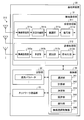
- FIG. 8 is a diagram showing a configuration example of the base station device 30 according to the embodiment of the present disclosure.
- the base station device 30 is a communication device (wireless system) that wirelessly communicates with the terminal device 20 under the control of the communication control device 40.
- the base station device 30 is a type of information processing device.
- the base station device 30 includes a wireless communication unit 31, a storage unit 32, a network communication unit 33, and a control unit 34.
- the configuration shown in FIG. 8 is a functional configuration, and the hardware configuration may be different from this. Further, the functions of the base station device 30 may be distributed and implemented in a plurality of physically separated devices.
- the wireless communication unit 31 is a wireless communication interface that wirelessly communicates with other communication devices (for example, a terminal device 20, a communication control device 40, a proxy device 50, and another base station device 30).
- the wireless communication unit 31 operates according to the control of the control unit 34.
- the wireless communication unit 31 may support a plurality of wireless access methods.
- the wireless communication unit 31 may support both NR and LTE.
- the wireless communication unit 31 may support other cellular communication methods such as W-CDMA and cdma2000.
- the wireless communication unit 31 may support a wireless LAN communication method in addition to the cellular communication method. Of course, the wireless communication unit 31 may only support one wireless access method.
- the wireless communication unit 31 includes a reception processing unit 311, a transmission processing unit 312, and an antenna 313.
- the wireless communication unit 31 may include a plurality of reception processing units 311 and transmission processing units 312, and a plurality of antennas 313, respectively.
- each unit of the wireless communication unit 31 may be individually configured for each wireless access method. For example, if the base station apparatus 30 corresponds to NR and LTE, the reception processing unit 311 and the transmission processing unit 312 may be individually configured by NR and LTE.
- the reception processing unit 311 processes the uplink signal received via the antenna 313.
- the reception processing unit 311 includes a wireless reception unit 311a, a multiple separation unit 311b, a demodulation unit 311c, and a decoding unit 311d.
- the radio receiver 311a performs down-conversion, removal of unnecessary frequency components, control of amplification level, orthogonal demodulation, conversion to digital signal, removal of guard interval, and fast Fourier transform of the frequency domain signal for the uplink signal. Extract, etc.
- the wireless access system of the base station device 30 is a cellular communication system such as LTE.
- the multiplex separation unit 311b separates the uplink channel such as PUSCH (Physical Uplink Shared Channel) and PUCCH (Physical Uplink Control Channel) and the uplink reference signal from the signal output from the wireless reception unit 311a.
- PUSCH Physical Uplink Shared Channel
- PUCCH Physical Uplink Control Channel
- the demodulation unit 311c demodulates the received signal with respect to the modulation symbol of the uplink channel by using a modulation method such as BPSK (Binary Phase Shift Keying) or QPSK (Quadrature Phase shift Keying).
- the modulation method used by the demodulation unit 311c may be 16QAM (Quadrature Amplitude Modulation), 64QAM, or 256QAM.
- the decoding unit 311d performs decoding processing on the coded bits of the demodulated uplink channel.
- the decoded uplink data and uplink control information are output to the control unit 34.
- the transmission processing unit 312 performs downlink control information and downlink data transmission processing.
- the transmission processing unit 312 includes a coding unit 312a, a modulation unit 312b, a multiplexing unit 312c, and a wireless transmission unit 312d.
- the coding unit 312a encodes the downlink control information and the downlink data input from the control unit 34 by using a coding method such as block coding, convolutional coding, or turbo coding.
- the modulation unit 312b modulates the coding bits output from the coding unit 312a by a predetermined modulation method such as BPSK, QPSK, 16QAM, 64QAM, 256QAM.
- the multiplexing unit 312c multiplexes the modulation symbol of each channel and the downlink reference signal and arranges them in a predetermined resource element.
- the wireless transmission unit 312d performs various signal processing on the signal from the multiplexing unit 312c.
- the radio transmitter 312d converts to the time domain by fast Fourier transform, adds a guard interval, generates a baseband digital signal, converts to an analog signal, quadrature modulation, up-conversion, and removes extra frequency components. Performs processing such as power amplification.
- the signal generated by the transmission processing unit 312 is transmitted from the antenna 313.
- the storage unit 32 is a storage device that can read and write data such as DRAM, SRAM, flash memory, and hard disk.
- the storage unit 32 functions as a storage means for the base station device 30.
- the storage unit 32 stores desired transmission power information, operating parameters, possessed resource information, and the like.
- the desired transmission power information is information on the transmission power required by the base station device 30 from the communication control device 40 as information on the transmission power required for transmitting radio waves.
- the operation parameter is information (for example, setting information) related to the radio wave transmission operation of the base station device 30.
- the operation parameter is information on the maximum value (maximum allowable transmission power) of the transmission power allowed in the base station apparatus 30.
- the operating parameters are not limited to the information on the maximum allowable transmission power.
- the possessed resource information is information regarding possession of the radio resource of the base station device 30.
- the possessed resource information is information on wireless resources currently available to the base station apparatus 30.
- the resource-rich information is information on the amount of interference margin held by the base station device 30 from the communication control device 40.
- the information on the holding amount may be information on a resource block unit described later. That is, the possessed resource information may be information about the resource block possessed by the base station apparatus 30 (for example, the resource block possession amount).
- the network communication unit 33 is a communication interface for communicating with other devices (for example, a communication control device 40, a proxy device 50, and another base station device 30).
- the network communication unit 43 is a LAN (Local Area Network) interface such as a NIC (Network Interface Card).
- the network communication unit 33 may be a USB interface composed of a USB (Universal Serial Bus) host controller, a USB port, and the like. Further, the network communication unit 33 may be a wired interface or a wireless interface.
- the network communication unit 33 functions as a network communication means of the base station device 30.
- the network communication unit 33 communicates with other devices according to the control of the control unit 34.
- the control unit 34 is a controller that controls each unit of the base station device 30.
- the control unit 34 is realized by, for example, a processor such as a CPU or MPU.
- the control unit 34 is realized by the processor executing various programs stored in the storage device inside the base station device 30 with the RAM or the like as a work area.
- the control unit 34 may be realized by an integrated circuit such as an ASIC or FPGA.
- the CPU, MPU, ASIC, and FPGA can all be regarded as controllers.
- the control unit 34 includes a selection unit 341, a calculation unit 342, a determination unit 343, a setting unit 344, a notification unit 345, and a wireless communication control unit 346.
- Each block (selection unit 341 to wireless communication control unit 346) constituting the control unit 34 is a functional block indicating the function of the control unit 34, respectively.
- These functional blocks may be software blocks or hardware blocks.
- each of the above-mentioned functional blocks may be one software module realized by software (including a microprocessor), or may be one circuit block on a semiconductor chip (die).
- each functional block may be one processor or one integrated circuit.
- the method of configuring the functional block is arbitrary.
- the control unit 34 may be configured in a functional unit different from the above-mentioned functional block.
- control unit 341, the calculation unit 342, the determination unit 343, and the notification unit 345 that form the control unit 34 are the selection unit 441, the calculation unit 442, the determination unit 443, and the notification unit 345 that form the control unit 44 of the communication control device 40. It may be the same as the operation of each block of the notification unit 445.
- the description of the "base station device 30" appearing in the following description can be appropriately replaced with the "communication control device 40".
- control unit 34 "selection unit 341", “calculation unit 342”, “decision unit 343”, and “notification unit 345" appearing in the following description are appropriately referred to as "control unit 44".
- control unit 34 does not necessarily have to include all of the selection unit 341, the calculation unit 342, and the determination unit 343.
- the control unit 34 distributes some or all blocks of the selection unit 341, the calculation unit 342, and the determination unit 343 among the control unit 24 of the terminal device 20 and the control unit 44 of the communication control device 40. Can be prepared.
- the communication control device 40 is a device that controls wireless communication of the base station device 30.
- the communication control device 40 may control the wireless communication of the terminal device 20 via the base station device 30 or directly.
- the communication control device 40 is a type of information processing device.
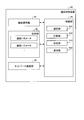
- FIG. 9 is a diagram showing a configuration example of the communication control device 40 according to the embodiment of the present disclosure.
- the communication control device 40 includes a wireless communication unit 41, a storage unit 42, a network communication unit 43, and a control unit 44.
- the configuration shown in FIG. 9 is a functional configuration, and the hardware configuration may be different from this. Further, the functions of the communication control device 40 may be distributed and implemented in a plurality of physically separated configurations.
- the communication control device 40 may be composed of a plurality of server devices.
- the wireless communication unit 41 is a wireless communication interface that wirelessly communicates with other communication devices (for example, a terminal device 20, a base station device 30, a proxy device 50, and another communication control device 40).
- the wireless communication unit 41 operates according to the control of the control unit 44.
- the wireless communication unit 41 corresponds to one or a plurality of wireless access methods.
- the wireless communication unit 41 corresponds to both NR and LTE.
- the wireless communication unit 41 may be compatible with other wireless access methods such as W-CDMA and cdma2000.
- the configuration of the wireless communication unit 41 is the same as that of the wireless communication unit 31 of the base station device 30.
- the storage unit 42 is a storage device that can read and write data such as DRAM, SRAM, flash memory, and hard disk.
- the storage unit 42 functions as a storage means for the communication control device 40.
- the storage unit 32 stores the operation parameters of each of the plurality of base station devices 30 constituting the communication system 2.
- the storage unit 42 may store the possessed resource information of each of the plurality of base station devices 30 constituting the communication system 2. As described above, the possessed resource information is information regarding the possession of the radio resource of the base station apparatus 30.
- the network communication unit 43 is a communication interface for communicating with other devices (for example, a base station device 30, a proxy device 50, and another communication control device 40).
- the network communication unit 43 may be a network interface or a device connection interface.
- the network communication unit 33 may be a LAN interface such as a NIC.
- the network communication unit 63 may be a USB interface composed of a USB host controller, a USB port, and the like.
- the network communication unit 43 may be a wired interface or a wireless interface.
- the network communication unit 43 functions as a communication means of the communication control device 40.
- the network communication unit 43 communicates with the terminal device 20, the base station device 30, and the proxy device 50 under the control of the control unit 44.
- the control unit 44 is a controller that controls each unit of the communication control device 40.
- the control unit 44 is realized by, for example, a processor such as a CPU or MPU.
- the control unit 44 is realized by the processor executing various programs stored in the storage device inside the communication control device 40 using the RAM or the like as a work area.
- the control unit 44 may be realized by an integrated circuit such as an ASIC or FPGA.
- the CPU, MPU, ASIC, and FPGA can all be regarded as controllers.
- the control unit 44 includes a selection unit 441, a calculation unit 442, a determination unit 443, and a notification unit 445.
- Each block of the selection unit 441, the calculation unit 442, the determination unit 443, and the notification unit 445 constituting the control unit 44 is a functional block indicating the function of the control unit 44, respectively.
- These functional blocks may be software blocks or hardware blocks.
- each of the above-mentioned functional blocks may be one software module realized by software (including a microprocessor), or may be one circuit block on a semiconductor chip (die).
- each functional block may be one processor or one integrated circuit.
- the method of configuring the functional block is arbitrary.
- the control unit 44 may be configured in a functional unit different from the above-mentioned functional block.
- FIG. 10 is a diagram showing a configuration example of the proxy device 50 according to the embodiment of the present disclosure.
- the proxy device 50 is a communication device that communicates with the base station device 30 and the communication control device 40.
- the proxy device 50 is a type of information processing device.
- the proxy device 50 includes a wireless communication unit 51, a storage unit 52, a network communication unit 53, and a control unit 54.
- the configuration shown in FIG. 10 is a functional configuration, and the hardware configuration may be different from this. Further, the functions of the proxy device 50 may be distributed and implemented in a plurality of physically separated configurations.
- the wireless communication unit 51 is a wireless communication interface that wirelessly communicates with other communication devices (for example, a terminal device 20, a base station device 30, a communication control device 40, and another proxy device 50).
- the wireless communication unit 51 operates according to the control of the control unit 54.
- the wireless communication unit 51 corresponds to one or a plurality of wireless access methods.
- the wireless communication unit 51 corresponds to both NR and LTE.
- the wireless communication unit 51 may be compatible with other wireless access methods such as W-CDMA and cdma2000.
- the configuration of the wireless communication unit 51 is the same as that of the wireless communication unit 31 of the base station device 30.
- the storage unit 52 is a storage device that can read and write data such as DRAM, SRAM, flash memory, and hard disk.
- the storage unit 52 functions as a storage means for the proxy device 50.
- the storage unit 52 may store desired transmission power information, operating parameters, possessed resource information, and the like of each of the subordinate base station devices 30.
- the network communication unit 53 is a communication interface for communicating with other devices (for example, a base station device 30, a communication control device 40, and another proxy device 50).
- the network communication unit 53 is a LAN interface such as a NIC.
- the network communication unit 53 may be a USB interface composed of a USB host controller, a USB port, and the like. Further, the network communication unit 53 may be a wired interface or a wireless interface.
- the network communication unit 53 functions as a network communication means of the proxy device 50.
- the network communication unit 53 communicates with other devices according to the control of the control unit 54.
- the control unit 54 is a controller that controls each unit of the proxy device 50.
- the control unit 54 is realized by, for example, a processor such as a CPU or MPU.
- the control unit 54 is realized by the processor executing various programs stored in the storage device inside the proxy device 50 with the RAM or the like as a work area.
- the control unit 54 may be realized by an integrated circuit such as an ASIC or FPGA.
- the CPU, MPU, ASIC, and FPGA can all be regarded as controllers.
- the control unit 54 includes a selection unit 541, a calculation unit 542, a determination unit 543, and a notification unit 545.
- Each block (selection unit 541 to notification unit 545) constituting the control unit 54 is a functional block indicating the function of the control unit 54, respectively.
- These functional blocks may be software blocks or hardware blocks.
- each of the above-mentioned functional blocks may be one software module realized by software (including a microprocessor), or may be one circuit block on a semiconductor chip (die).
- each functional block may be one processor or one integrated circuit.
- the method of configuring the functional block is arbitrary.
- the control unit 54 may be configured in a functional unit different from the above-mentioned functional block.
- each block of the selection unit 541, the calculation unit 542, the determination unit 543, and the notification unit 545 constituting the control unit 54 is the selection unit 441, the calculation unit 442, and the determination unit constituting the control unit 44 of the communication control device 40. It may be the same as each block operation of 443 and the notification unit 445. In this case, the description of the "proxy device 50" appearing in the following description can be appropriately replaced with the "communication control device 40".
- control unit 54 controls the operations of "control unit 54", "selection unit 541”, “calculation unit 542”, “decision unit 543”, and “notification unit 545" appearing in the following description are appropriately described in “control unit 44”, It can be replaced with “selection unit 441”, “calculation unit 442”, “decision unit 443”, and “notification unit 445".
- FIG. 11 is an explanatory diagram showing an example of an interference model assumed in the embodiment of the present disclosure.
- the description of the base station device 30 that appears in the following description can be replaced with a word indicating another communication device having a wireless communication function.
- the interference model shown in FIG. 11 is applied, for example, when the primary system has a service area.
- the communication system 1 primary system
- the communication system 1 is a wireless communication system having a service area.
- This service area becomes, for example, a protected area of the communication system 1.
- a plurality of interference calculation reference points (hereinafter referred to as protection points) are set in the protection area.
- the protection point is set, for example, by the operator of the communication system 1 or a public institution that manages radio waves (hereinafter referred to as an administrator).
- the administrator may divide the protected area in a grid pattern and use the center of a predetermined grid as a protection point.
- the method of determining the protection point is arbitrary.
- the interference margin of each protection point is set by the administrator or the like.
- FIG. 11 shows the interference that the plurality of base station devices 30 constituting the communication system 2 (secondary system) give to the protection points.
- the communication control device 40 of the communication system 2 controls the transmission power of the plurality of base station devices 30 so that the cumulative interference at each protection point does not exceed the set interference margin.
- FIG. 12 is an explanatory diagram showing another example of the interference model assumed in the embodiment of the present disclosure.
- the interference model shown in FIG. 12 is applied, for example, when the primary system performs only reception.
- the communication system 1 primary system
- the ground fixed communication terminal 10C 1 is, for example, a receiving antenna of a satellite ground station.
- the communication control device 40 of the communication system 2 uses the position of the receiving antenna as a protection point, and controls the transmission power of the plurality of base station devices 30 so that the cumulative interference at that point does not exceed the interference margin.
- the primary system protection method can be classified into the following two types, for example.
- the interference margin simultaneous distribution type primer system protection method for example, the method disclosed in Non-Patent Document 3 (for example, the calculation method of the maximum allowable EIRP) can be mentioned.
- the interference margin sequential allocation type primer system protection method for example, the sequential allocation process (IAP: Iterative Allocation Process) disclosed in Non-Patent Document 6 can be mentioned.
- FIG. 13 is an explanatory diagram for explaining a method of protecting the primer system of the interference margin simultaneous distribution type.
- the communication control device 40 calculates the maximum allowable transmission power of the secondary system using "a value uniquely obtained by the positional relationship between the protection reference point of the primary system and the secondary system" as a reference value.
- the allowable interference threshold of the primary system is Iaccept .
- This threshold value may be an actual threshold value, or may be a value set in consideration of a calculation error and interference fluctuations and a certain margin (for example, Protection Ratio) from the actual threshold value.
- interference control means determining the transmission power (EIRP, Conducted Power + Antenna gain, etc.) of the wireless device so as not to exceed the allowable interference threshold. At this time, if there are many base station devices 30 and each of them does not exceed the allowable interference threshold value, the interference power received in the communication system 1 (primary system) may exceed the allowable interference threshold value. .. Therefore, the interference margin (allowable interference amount) is "allocated" based on the number of base station devices 30 registered in the communication control device 40.
- the total number of base station devices 30 is 5. Therefore, the permissible interference amount of I accident / 5 is allocated to each individual. Since the base station device 30 cannot recognize this distribution amount by itself, it recognizes it through the communication control device or acquires the transmission power determined based on this distribution amount. Since the communication control device cannot recognize the number of wireless devices managed by other communication control devices, the total number can be recognized and the allowable interference amount can be distributed by exchanging information with each other. Become. For example, the allowable interference quantity of 3I the accept / 5 is assigned by the communication control unit 40 within 1.
- the interference margin not used by the base station apparatus 30 can be a residual interference margin.
- FIG. 14 is a diagram showing how a residual interference margin is generated.
- FIG. 14 shows the total amount of interference set for each of the two communication control devices 40 (communication control devices 40 1 , 402).
- a plurality of base station apparatuses 30 under management of the two communication control device 40 the amount of interference given to the predetermined protection point (base station apparatus 30 1 to 30 5) in the communication system 1 (Interference Amount) is shown.
- the interference amount obtained by subtracting the interference amount by the base station device 30 from the total interference amount of each of the two communication control devices 40 is the residual interference margin.
- the surplus interference amount is referred to as a surplus interference margin.
- the residual interference margin can be rephrased as the amount of residual interference.
- each of the plurality of base station devices 30 stores desired transmission power information in the storage unit 22.
- the desired transmission power information is information on the transmission power required by the base station device 30 from the communication control device 40 as information on the transmission power required for transmitting radio waves.
- the base station devices 30 1 to 30 4 each hold desired transmission power information A to D.
- the communication control device 40 and assigns the respective interference amount A ⁇ D in the base station apparatus 30 1 to 30 4 based on the desired transmission power information A ⁇ D.
- the registration procedure is a procedure for registering device parameters related to the base station device 30 in the communication control device 40.
- the base station device 30 or one or more communication systems including the plurality of base station devices 30 start the registration procedure by notifying the communication control device 40 of a registration request including the device parameters.
- the registration request may be transmitted by a communication system (for example, a proxy system such as a proxy device 50) representing (representing) one or a plurality of base station devices 30.
- the communication system representing (representing) a plurality of base station devices 30 is the proxy device 50, but the word of the proxy device 50 appearing in the following description is another communication such as a proxy system. It can be replaced with a word indicating a communication system that represents (represents) the device.
- the device parameter refers to, for example, the information shown below.
- Communication device-specific information Location information Antenna information Wireless interface information Legal information Installer information Information other than these may be treated as device parameters when implementing.
- the information unique to the communication device is information that can identify the base station device 30, information about the hardware of the base station device 30, and the like. For example, a serial number, a product model number, etc. may be included.
- Information that can identify the base station device 30 refers to communication device user information, communication device serial number, and the like.
- a user ID, a call sign, or the like can be assumed as the communication device user information.
- the user ID may be independently generated by the communication device user, or may be issued in advance by the communication control device 40.
- Information on the hardware of the base station device 30 may include, for example, transmission power class information, manufacturer information, and the like.
- transmission power class information for example, in FCC C.F.R Part 96, two types of classes, Category A and Category B, are defined, and any information may be included.
- some classes of eNodeB and gNodeB are specified in 3GPP TS 36.104 and TS 38.104, and these can also be used.
- the information about the software of the base station device 30 may include, for example, version information and a build number related to an execution program in which the processing necessary for interaction with the communication control device 40 is described.
- software version information and a build number for operating as the base station device 30 may also be included.
- the information related to the position is typically information that can specify the geographical position of the base station device 30.
- it is coordinate information acquired by a positioning function represented by GPS (Global Positioning System), Beidou, QZSS (Quasi-Zenith Satellite System), Galileo and A-GPS (Assisted Global Positioning System).
- GPS Global Positioning System
- Beidou Beidou
- QZSS Quadasi-Zenith Satellite System
- Galileo Galileo
- A-GPS Assisted Global Positioning System
- it may include information about latitude, longitude, altitude, and positioning error.
- it may be location information registered in an information management device managed by NRA (National Regulatory Authority) or its consignment organization.
- the coordinates may be the X-axis, Y-axis, and Z-axis having a specific geographic position as the origin. Further, an identifier indicating outdoor / indoor can be given together with such coordinate information.
- the information related to the position may be information indicating the area where the base station device 30 is located.
- information determined by the government such as a zip code and an address, may be used.
- a region may be indicated by a set of three or more geographic coordinates. Information indicating these regions may be provided together with the above coordinate information.
- information indicating the floor of the building may be added to the information related to the position. For example, an identifier indicating the number of floors, above ground / underground, or the like may be assigned. Further, for example, information indicating a further closed space indoors may be added, such as a room number and a room name in the building.
- the positioning function is typically provided by the base station device 30. However, depending on the performance of the positioning function and the installation position, it is not always possible to acquire position information that satisfies the required accuracy. Therefore, the positioning function may be used by the installer. In such a case, it is desirable that the position information measured by the installer is written in the base station device 30.
- the antenna information is typically information indicating the performance, configuration, and the like of the antenna included in the base station apparatus 30. Typically, it may include information such as antenna installation height, tilt angle (Downtilt), horizontal orientation (Azimuth), aiming (Boresight), antenna peak gain, and antenna model.
- the antenna information may include information about the beam that can be formed. For example, information such as beam width, beam pattern, and analog / digital beamforming capabilities can be included.
- the antenna information may include information on the performance and configuration of MIMO (Mutiple Input Multiple Output) communication. For example, information such as the number of antenna elements and the maximum number of spatial streams may be included.
- codebook information to be used unitary matrix obtained by weight matrix information (SVD (Singular Value Decomposition), EVD (Eigen Value Decomposition), BD (Block Diagonalization), etc., ZF (Zero-Forcing) matrix, MMSE (Minimum Mean Square Error) matrix) etc. can also be included.
- MLD Maximum Likelihood Detection
- MLD Maximum Likelihood Detection
- the above antenna information may include ZoD (Zenith of Direction, Departure).
- the ZoD is a kind of radio wave arrival angle.
- the ZoD may be estimated by another base station device 30 from radio waves radiated from the antenna of the base station device 30.
- the base station device 30 may be a terminal device that operates as a base station or an access point, a device that performs D2D communication, a moving relay base station, or the like.
- ZooD can be estimated by radio wave arrival direction estimation technology such as MUSIC (Multiple Signal Classification) or ESPRIT (Estimation of Signal Propagation via Rotation Invariance Techniques). It can be used by the communication control device 40 as measurement information.
- MUSIC Multiple Signal Classification
- ESPRIT Estimatiation of Signal Propagation via Rotation Invariance Techniques
- the wireless interface information is typically information indicating the wireless interface technology included in the base station apparatus 30.
- technologies used in GSM registered trademark
- LTE-compliant derivatives such as MultFire and LTE-U (LTE-Unlicensed).
- the version number or release number of the technical specification that defines these may also be assigned. It does not necessarily have to be a standard technology and may include information indicating proprietary wireless technology.
- the wireless interface information may also include frequency band information supported by the base station apparatus 30.
- frequency band information supported by the base station apparatus 30.
- it can be expressed by one or more combinations of upper limit frequency and lower limit frequency, one or more combinations of center frequency and bandwidth, or one or more 3GPP Operating Band numbers.
- the frequency band information supported by the base station apparatus 30 may also include capability information of carrier aggregation (CA: Carrier Aggregation) and channel bonding (Channel Bonding). For example, it may include band information that can be combined.
- carrier aggregation may include information on the band to be used as a primary component carrier (PCC: Primary Component Carrier) or a secondary component carrier (SCC: Secondary Component Carrier). It may also include the number of CCs that can be aggregated at the same time.
- PCC Primary Component Carrier
- SCC Secondary Component Carrier
- information indicating the radio wave usage priority such as PAL and GAA may be included.
- the wireless interface information may also include modulation method information supported by the base station apparatus 30.
- modulation method information supported by the base station apparatus 30.
- FSK Frequency Shift Keying
- n-value PSK Phase Shift Keying
- n-value QAM Quadrature Amplitude Modulation
- n 4, 16, 64.
- OFDM Orthogonal Frequency Division Multiplexing
- DFT-s-OFDM DFT spread OFDM
- FBMC Fan Bank Multi Carrier
- the wireless interface information may include information on an error correction code.
- it may include capabilities such as a Turbo code, an LDPC (Low Density Parity Check) code, and a Polar code, and code rate information to be applied.
- LDPC Low Density Parity Check
- MCS Modulation and Coding Scheme
- the wireless interface information may include information indicating a function peculiar to each wireless technology supported by the base station apparatus 30.
- TM Transmission Mode
- LTE Long Term Evolution
- those having two or more modes for a specific function can be included in the wireless interface information as in the above TM.
- information indicating this may be included.
- the wireless interface information may also include wireless access system (RAT: Radio Access Technology) information supported by the base station device 30.
- RAT Radio Access Technology
- TDMA Time Division Multiple Access
- FDMA Frequency Division Multiple Access
- OFDMA Orthogonal Frequency Division Multiple Access
- OMA Orthogonal Multiple Access
- PDMA Power Division Multiple Access, Superposition Coding (SPC)
- SIC Successive Interference Canceller
- CDMA Code Division Multiple Access
- SCMA Separatse Code Multiple Access
- IDMA Interleaver Division Multiple Access
- SDMA Spatial Division Multiple
- NOMA Non Orthogonal Multiple Access
- CSMA / CA Carrier Sense Multiple Access / Collision Avoidance
- CSMA / CD Carrier Sense Multiple Access / Collision Detection
- the wireless interface information may also include information related to the duplex mode supported by the base station apparatus 30.
- information related to the duplex mode supported by the base station apparatus 30 can be included.
- FDD Frequency Division Duplex
- TDD Time Division Duplex
- FD Frequel Duplex
- TDD Frame Configuration information used / supported by the base station device 30 can be added.
- information related to the duplex mode may be included for each frequency band indicated by the above frequency band information.
- the wireless interface information may also include information about the transmission diversity method supported by the base station apparatus 30.
- spatiotemporal coding STC: Space Time Coding
- STC Space Time Coding
- the wireless interface information may also include guard band information.
- it may contain information about the standard guard band size.
- information about the guard band size desired by the base station apparatus 30 may be included.
- Legal information is typically information on regulations that the base station device 30 must comply with, which is set by the radio wave administration agency of each country / region or an agency equivalent thereto, and the information acquired by the base station device 30. It is authentication information and so on.
- the information regarding the above regulation may typically include, for example, information on the upper limit of out-of-band radiation, information on the blocking characteristics of the receiver, and the like.
- Typical of the above certification information is, for example, type approval (Type Approval) information (FCC ID, technical standard conformity certification, etc.), legal and regulatory information (for example, FCC rule number, ETSI Harmonized Standard number, etc.) that is the basis for obtaining certification. ) Etc. may be included.
- the information specified in the wireless interface technology standard may be substituted.
- the upper limit value information of out-of-band radiation may be derived and used by using the adjacent channel leakage ratio (ACLR: Adjacent Channel Leakage Ratio).
- ACLR Adjacent Channel Leakage Ratio
- adjacent channel selectivity ACS: Adjacent Channel Selectivity
- ACIR Adjacent Channel Interference Ratio
- the installer information may include information that can identify the person (installer) who installed the base station device 30, information unique to the installer, and the like.
- CPIR-ID Cosmetic Professional Installer Registration ID
- CPI name is disclosed as information that can identify the installer.
- unique information associated with the installer for example, a contact address (Mailing / Contact address), an e-mail address, a telephone number, a PKI (Public Key Identifier), and the like are disclosed. Not limited to these, other information about the installer may be included as needed.
- FIG. 16 is a sequence diagram for explaining the registration procedure.
- the base station device 30 or one or more communication systems including the plurality of base station devices 30 generate a registration request message using the device parameters (step S11) and notify the communication control device 40 (step S12).
- the proxy device 50 may generate and / or notify the message.
- the registration request may be processed to prevent tampering by using this information.
- a part or all of the information included in the registration request may be encrypted.
- a process in which a public key peculiar to the installer is shared in advance between the installer and the communication control device 40, and the installer encrypts the information using the private key. can be implemented.
- the target of encryption includes, for example, security-sensitive information such as location information.
- the installer may directly write in the communication control device 40.
- the communication control device 40 After receiving the registration request, the communication control device 40 executes the registration process of the base station device 30 (step S13), and returns a registration response according to the process result (step S14). If the information required for registration is insufficient or abnormal, the communication control device 40 records the information in the storage unit 42 and notifies the completion of normal operation. Otherwise, the communication control device 40 notifies the registration failure. When the registration is normally completed, the communication control device 40 may assign an ID to each communication device and notify the ID information by enclosing it at the time of response. In the event of a registration failure, typically one or more communication systems, including base station equipment 30 or multiple base station equipment 30, or operators (eg, mobile operators or individuals) or installers thereof. , Correct the registration request, etc., and try the registration procedure until it is completed normally.
- a registration failure typically one or more communication systems, including base station equipment 30 or multiple base station equipment 30, or operators (eg, mobile operators or individuals) or installers thereof. , Correct the registration request, etc., and try the registration procedure until it
- the registration procedure may be executed multiple times. Specifically, the registration procedure can be re-executed when the position information is changed beyond a predetermined standard due to, for example, movement / accuracy improvement.
- Predetermined standards are typically set by the legal system. For example, in 47 C.F.R Part 15, Mode II personal / portable white space device is obliged to access the database again when the location information changes by 100 meters or more.
- the available frequency information inquiry procedure is a procedure in which the base station device 30 or the proxy device 50 inquires the communication control device 40 for information on available frequencies. Typically, the base station device 30 or the proxy device 50 notifies the communication control device 40 of an inquiry request including information that can identify the base station device 30 (or the base station device 30 under the proxy device 50). This will start the procedure.
- Example 1 the available frequency information is typically safe without causing fatal interference to the primary system at the position of the base station device 30 (or the base station device 30 under the proxy device 50). It is information indicating the frequencies that can be secondarily used. For example, when the base station device 30 is installed in a secondary use prohibited area such as an exclusion zone in order to protect the primary system using the frequency channel F1, the base station device 30 is subjected to. The frequency channel F1 is not notified as an available channel.
- Example 2 Further, for example, even outside the secondary use prohibited area, if it is determined to cause fatal interference to the primary system, the frequency channel may not be notified as an available channel.
- Example 3 there may be a frequency channel in which the available frequency information is not notified as available due to conditions other than the primary system protection requirement of Example 2. Specifically, for example, in order to avoid interference that may occur between the base station devices 30 in advance, other devices existing in the vicinity of the base station device 30 (or the base station device 30 under the proxy device 50). In some cases, the base station apparatus 30 does not notify the frequency channel in use as an available channel.
- Example 4 Even in these cases (Examples 2 and 3), it is possible to notify the same frequency as the primary system or the nearby base station apparatus 30 as an available channel.
- the maximum permissible transmit power information is typically included in the available frequency information.
- the maximum permissible transmit power is typically expressed in terms of equivalent isotropic radiated power (EIRP). It is not necessarily limited to this, and may be provided, for example, in a combination of antenna power and antenna gain. Feeder Loss may also be included. Further, as the antenna gain, an allowable peak gain may be set for each spatial direction.
- EIRP equivalent isotropic radiated power
- Inquiry request information may also include inquiry requirement information.
- the inquiry requirement information may include, for example, information indicating a frequency band for which it is desired to know whether or not it is available.
- transmission power information may be included.
- the base station device 30 or the proxy device 50 may include the transmission power information, for example, when it is desired to know only the frequency information in which the desired transmission power can be used. Inquiry requirement information does not necessarily have to be included.
- the inquiry request may also include a measurement report.
- the measurement report includes the results of the measurement performed by the base station device 30 and / or the terminal device 20. For example, it can include processed information as well as raw data. For example, standardized metrics represented by RSRP (Reference Signal Received Power), RSSI (Reference Signal Strength Indicator), and RSRQ (Reference Signal Received Quality) can be used.
- RSRP Reference Signal Received Power
- RSSI Reference Signal Strength Indicator
- RSRQ Reference Signal Received Quality
- FIG. 17 is a sequence diagram for explaining an available frequency information inquiry procedure.
- the base station device 30 or the proxy device 50 generates an inquiry request including information that can identify the base station device 30 (or the base station device 30 under the proxy device 50) (step S21), and sends the communication control device 40 to the communication control device 40. Notify (step S22).
- the communication control device 40 After receiving the inquiry request, the communication control device 40 evaluates the available frequency based on the inquiry requirement information (step S23). For example, as described in Examples 1 to 3 described above, it is possible to evaluate the available frequency in consideration of the existence of the primary system, its secondary use prohibited area, and the nearby base station device 30.
- the communication control device 40 may derive the maximum allowable transmission power information.
- the distance between P MaxTx (dBm) is the maximum permitted transmission power
- I Th (dBm) is acceptable interference power
- d is the reference position and (Reference Point) and the base station apparatus 30,
- PL (d) (dB ) Is the propagation loss at the distance d.
- the antenna gain in the transmitter / receiver is not explicitly shown in this formula, it can be used as a reference point for the maximum allowable transmission power (EIRP, Conducted power, etc.) and reception power (antenna input point, antenna output point, etc.). May be included accordingly.
- a safety margin or the like for compensating for fluctuations due to fading may be included.
- feeder loss and the like may be considered as necessary.
- the above mathematical formula is described based on the assumption that the single base station device 30 is the interference source. For example, when it is necessary to consider the cumulative interference from a plurality of base station devices 30 at the same time, a correction value may be added. Specifically, for example, the correction value can be determined based on the interference margin method of three types (Fixed / Predetermined, Flexible, Flexible Minimized) disclosed in Non-Patent Document 3.
- Method 1 when the transmission power information is included in the inquiry requirement information, the available frequency may be evaluated by a method different from the above method. It is possible. Specifically, for example, when it is assumed that the desired transmission power indicated by the transmission power information is used, the estimated interference amount is less than the allowable interference power in the primary system or its protection zone. Is determined that the frequency channel is available and notified to the base station device 30 (or proxy device 50).
- Evaluation of available frequencies does not necessarily have to be performed after receiving an inquiry request.
- the communication control device 40 may independently execute the registration procedure without requesting an inquiry.
- the communication control device 40 may create the REM or the look-up table exemplified in the method 2 or an information table similar to them.
- the radio wave usage priority such as PAL or GAA may be evaluated.
- the registered device parameter or the inquiry requirement includes information on the radio wave usage priority, it may be determined and notified whether the frequency can be used based on the priority.
- information on a base station apparatus 30 that is used by a user with high priority (for example, PAL) in advance in Non-Patent Document 2, it is called Cluser List).
- the evaluation may be performed based on the information.
- the communication control device 40 After the evaluation of the available frequency is completed, the communication control device 40 notifies the base station device 30 (or the proxy device 50) of the evaluation result (step S24).
- the base station apparatus 30 may select desired communication parameters by using the evaluation result received from the communication control apparatus 40.
- the frequency use permission procedure is a procedure for the base station device 30 to receive a secondary frequency use permission from the communication control device 40.
- one or more communication systems including the base station apparatus 30 or a plurality of base station apparatus 30 communicate a frequency usage permission request containing information that can identify the base station apparatus 30.
- the procedure is started by notifying the control device 40. This notification may be made by the proxy device 50. Note that "after the normal completion of the registration procedure" also means that it is not always necessary to carry out the available frequency information inquiry procedure.
- the designation method is a request method in which the base station device 30 specifies at least the frequency band to be used and the maximum transmission power as desired communication parameters, and requests the communication control device 40 for permission to operate based on the desired communication parameters. It is not always necessary to be limited to these parameters, and parameters specific to the wireless interface technology (modulation method, duplex mode, etc.) may be specified. In addition, information indicating radio wave usage priority such as PAL and GAA may be included.
- the flexible method is a request method in which the base station device 30 specifies only the requirements related to the communication parameters, and requests the communication control device 40 to specify the communication parameters that can be permitted to be used secondarily while satisfying the requirements.
- Requirements for communication parameters may include bandwidth or desired maximum transmit power or desired minimum transmit power. It is not always necessary to be limited to these parameters, and parameters specific to the wireless interface technology (modulation method, duplex mode, etc.) may be specified. Specifically, for example, one or more of TDD Frame Configuration may be selected in advance and notified.
- a measurement report may be included.
- the measurement report includes the results of the measurement performed by the terminal device 20 and / or the base station device 30.
- it can include processed information as well as raw data.
- standardized metrics represented by RSRP (Reference Signal Received Power), RSSI (Reference Signal Strength Indicator), and RSRQ (Reference Signal Received Quality) can be used.
- FIG. 18 is a sequence diagram for explaining the frequency use permission procedure.
- the base station device 30 or one or more communication systems including the plurality of base station devices 30 generate a frequency use permission request including information that can identify the base station device 30 (step S31), and notify the communication control device 40. (Step S32).
- the proxy device 50 may generate and / or notify the request.
- the frequency use permission request is acquired, for example, by the acquisition unit of the communication control device 40.
- the communication control device 40 After acquiring the frequency use permission request, the communication control device 40 performs the frequency use permission process based on the frequency use permission request method (step S33). For example, the communication control device 40 has ⁇ 5-2. Using the method described in Examples 1 to 3 of the Usable Frequency Information Inquiry Procedure>, frequency usage permission processing is performed in consideration of the existence of the primary system, its secondary usage prohibited area, and the nearby base station device 30. It is possible.
- the communication control device 40 When the flexible method is used, the communication control device 40 is set to ⁇ 5-2.
- the maximum allowable transmission power information may be derived by using the method described in Example 4 of the available frequency information inquiry procedure>.
- the communication control device 40 provides permissible interference power information in the primary system or its protection zone, reference point information on the interference power level suffered by the primary system, and the base station device 30. Calculate the maximum allowable transmission power using the registration information and the propagation loss estimation model. For example, the communication control device 40 calculates the maximum allowable transmission power by the following equation (2).
- P MaxTx (dBm) I Th (dBm) + PL (d) (dB) ... (2)
- the distance between P MaxTx (dBm) is the maximum permitted transmission power
- I Th (dBm) is acceptable interference power
- d is the reference position and (Reference Point) and the base station apparatus 30,
- PL (d) (dB ) Is the propagation loss at the distance d.
- the antenna gain in the transmitter / receiver is not explicitly shown in this formula, it can be used as a reference point for the maximum allowable transmission power (EIRP, Conducted power, etc.) and reception power (antenna input point, antenna output point, etc.).
- the mathematical formula may be modified accordingly.
- a safety margin or the like for compensating for fluctuations due to fading may be included.
- feeder loss and the like may be considered as necessary.
- the above mathematical formula is described based on the assumption that the single base station device 30 is the interference source. For example, when it is necessary to consider the cumulative interference from a plurality of base station devices 30 at the same time, a correction value may be added. Specifically, for example, the correction value can be determined based on the three types (Fixed / Predetermined, Flexible, Flexible Minimized) disclosed in Non-Patent Document 3.
- Non-Patent Document 6 a propagation loss model such as eHATA (Extended Hata) or ITM (Irregular Terrain Model) is adopted for each application.
- eHATA Extended Hata
- ITM International Terrain Model
- the propagation loss model need not be limited to these.
- the model is not specified for the specified purpose, it may be used properly as needed.
- an aggressive model such as a free space loss model when estimating the interference power to another base station device 30.
- Method 1 of Usable Frequency Information Inquiry Procedure> it is possible to perform frequency usage permission processing using the method described in Method 1 of Usable Frequency Information Inquiry Procedure>. Specifically, for example, when it is assumed that the desired transmission power indicated by the transmission power information is used, the estimated interference amount is less than the allowable interference power in the primary system or its protection zone (Protection Zone). Is determined that the use of the frequency channel can be permitted, and the base station device 30 (or the proxy device 50) is notified.
- the radio wave usage priority such as PAL or GAA may be evaluated.
- the registered device parameter or the inquiry requirement includes information on the radio wave usage priority, it may be determined and notified whether the frequency can be used based on the priority.
- information on a base station apparatus 30 that is used by a user with high priority (for example, PAL) in advance in Non-Patent Document 2, it is called Cluser List).
- the evaluation may be performed based on the information.
- the frequency usage permission process does not necessarily have to be performed when the request is received.
- the communication control device 40 may take the initiative in executing the frequency usage permission request.
- the frequency use permission determination process may be performed at regular intervals. In such a case, ⁇ 5-2. REM and look-up table illustrated in Method 2 of Available frequency information inquiry procedure> An information table similar to them may be created.
- the communication control device 40 After the frequency usage permission process is completed, the communication control device 40 notifies the base station device 30 of the determination result (step S34).
- the frequency usage notification is a procedure in which the base station device 30 or the proxy device 50 notifies the communication control device 40 of the frequency usage based on the communication parameters permitted to be used in the frequency usage permission procedure. .. Typically, the base station device 30 or the proxy device 50 starts the procedure by notifying the communication control device 40 of a notification message including information that can identify the base station device 30.
- this procedure be carried out periodically until the use of the frequency is rejected by the communication control device 40. If this procedure is successfully completed, the base station apparatus 30 may start or continue radio wave transmission. For example, if the Grant status was Granted, the success of this procedure will shift the Grant status to Enhanced. Also, if the grant status is Enhanced, the grant status shifts to Granted or Idol due to the failure of this procedure.
- the grant is an authorization for radio wave transmission given to the base station device 30 (for example, CBSD) by the communication control device 40 (for example, SAS).
- Grant can be rephrased as a license to use radio wave resources (frequency resources).
- This grant is described, for example, in Non-Patent Document 2.
- Non-Patent Document 2 standardizes a signaling protocol between a database (SAS) and a base station (CBSD) for frequency sharing of 3550-3700 MHz in the United States.
- SAS database
- CBSD base station
- the operating parameters recognized by Grant are defined by the maximum allowable EIRP (Equivalent Isotropic Radiated Power) and the frequency channel. That is, in order to transmit radio waves using a plurality of frequency channels, the CBSD needs to acquire a plurality of grants from the SAS.
- EIRP Equivalent Isotropic Radiated Power
- the grant has a defined state that indicates the permitted state of radio wave transmission.
- FIG. 19 is a state transition diagram showing a permitted state of radio wave transmission.
- the Granted state indicates a state in which a grant is possessed but radio waves must not be transmitted
- the Enhanced state indicates a state in which radio wave transmission is permitted based on an operation parameter value defined by the grant.
- the frequency usage notification may be referred to as a heartbeat request (Heartbeat Request) or simply a heartbeat (Heartbeat).
- Heartbeat Request the transmission interval of the heartbeat request
- Heartbeat Interval the heartbeat interval
- the description of Heartbeat Request or Heartbeat appearing in the following description can be appropriately replaced with another description indicating "request for starting or continuing radio wave transmission”.
- the heartbeat interval can be replaced with another description (for example, transmission interval) indicating the transmission interval of the frequency utilization notification.
- FIG. 20 is a sequence diagram for explaining the frequency usage notification procedure.
- the base station device 30 or one or more communication systems including the plurality of base station devices 30 generate a notification message including information that can identify the base station device 30 (step S41), and notify the communication control device 40 (step S41). Step S42).
- the proxy device 50 may generate and / or notify the message.
- the communication control device 40 may determine whether the start / continuation of radio wave transmission is permitted (step S43).
- a determination method for example, confirmation of frequency usage information of the primary system can be mentioned. Specifically, it is decided to start / continue permission or refusal of radio wave transmission based on changes in the frequency used by the primary system, changes in the frequency usage status of the primary system (for example, carrier-based radar) whose radio wave usage is not steady, etc. It is possible to do.
- the communication control device 40 notifies the base station device 30 (or the proxy device 50) of the determination result (step S44).
- the communication control device 40 may issue a communication parameter reconfiguration command to the base station device 30 (or proxy device 50). Typically, it can be implemented in the response of the frequency utilization notification. For example, recommended communication parameter information may be provided.
- the procedures do not necessarily have to be implemented individually, as described below.
- the above two different procedures may be realized by substituting a third procedure having the roles of two different procedures.
- the registration request and the available frequency information inquiry request may be notified integrally.
- the frequency use permission procedure and the frequency use notification may be carried out integrally.
- the combination is not limited to these, and may be three or more.
- the above procedure may be carried out separately.
- the expression "acquire information” or an expression equivalent thereto in the present embodiment does not necessarily mean to acquire according to the above procedure.
- the position information of the base station device 30 is used in the available frequency evaluation process, it is not always necessary to use the information acquired in the registration procedure, and the available frequency inquiry procedure request includes the position information. If so, it means that the position information may be used. In other words, it means that the described parameters may be included in other procedures within the scope described in this embodiment and within the technical feasibility.
- the information that can be included in the response from the communication control device 40 to the base station device 30 (or the proxy device 50) shown in the above procedure may be push-notified.
- available frequency information, recommended communication parameter information, radio wave transmission continuation refusal notification, and the like may be push notifications.
- Operational Parameters are defined in the non-patent document as "operation parameters specific to a specific slave WSD (White Space Device)".
- operation parameters specific to a specific slave WSD White Space Device
- it is a communication parameter calculated by using the device parameter of the slave WSD corresponding to the terminal device 20.
- WSDB White Space Database
- Operational Parameters are defined in the non-patent document as "operation parameters that can be used by any slave WSD located within the coverage area of a predetermined master WSD (corresponding to the base station device 30)". There is. As a feature, it is calculated by WSDB without using the position information of the slave WSD.
- a broadcast signal represented by CVS (Contact Verification Signal) defined by the FCC rule Part 15 Subpart H can be used.
- CVS Contact Verification Signal
- it may be provided by a broadcast signal specific to the wireless interface.
- PBCH Physical Broadcast Channel
- NR-PBCH Physical Broadcast Channel
- FIG. 21 is a sequence diagram for explaining a procedure for exchanging management information.
- the communication control device 40 2 are exchanging information with the communication control device 40 1.
- the communication control unit for exchanging information is not limited to two communication control device 40 1 and the communication control unit 40 2.
- the communication device registration information is typically a device parameter of the base station device 30 registered in the communication control device 40 in the above registration procedure. Not all registered information need to be exchanged. For example, information that may correspond to personal information does not need to be exchanged. Further, when exchanging the communication device registration information, the encrypted / ambiguous information may be exchanged. For example, information converted into a binary value or information signed using an electronic signature mechanism may be exchanged.
- the communication device communication parameter information is typically information related to the communication parameters currently used by the base station device 30. At a minimum, it is desirable to include information indicating the frequency used and the transmission power. Other communication parameters may be included.
- Area information is typically information that indicates a predetermined geographical area. This information may include domain information of various attributes in various aspects.
- the protected area information of the base station device 30 which is a high priority secondary system such as PPA (PAL Protection Area) disclosed in Non-Patent Document 5 may be included.
- the area information in this case can be represented by, for example, a set of three or more geographic position coordinates.
- a plurality of communication control devices 40 can refer to a common external database, it can be represented by an ID indicating the information.
- information indicating the coverage of the base station apparatus 30 may be included.
- the area information in this case can also be represented by, for example, a set of three or more geographic position coordinates. Further, for example, assuming a circle whose origin is the geographical position of the base station device 30, it can also be expressed by information indicating the radius size. Further, for example, when a plurality of communication control devices 40 can refer to a common external database, it can be represented by an ID indicating the information.
- information on area divisions predetermined by the government or the like may be included. Specifically, for example, it is possible to indicate a certain area by indicating an address. Further, for example, a license area and the like can be expressed in the same manner.
- the area information does not necessarily have to represent a flat area, and may represent a three-dimensional space.
- it may be expressed using a spatial coordinate system.
- information indicating a predetermined closed space such as the number of floors of the building, the floor or the room number may be used.
- the ID designation method is a method of acquiring information corresponding to the above ID by using an ID assigned in advance for specifying the information managed by the communication control device 40.
- ID Assume the communication control device 40 1 to the base station apparatus 30 that AAA is managing. In this case the communication controller 40 2 to, ID to the communication control device 401: acquires information request with AAA. After receiving the request, the communication control device 40 1 with an ID: performs AAA information retrieval, and notifies the registration information of the base station apparatus 30 applicable, the communication parameter information in response.
- a specific period can be specified, and information satisfying a predetermined condition can be exchanged during the period.
- the predetermined condition is, for example, whether or not the information is updated. For example, when acquisition of communication device information in a specific period is specified in the request, communication with the registration information of the base station device 30 newly registered in the period and the registration information of the base station device 30 whose communication parameters have been changed. Parameter information can be notified in the response.
- the predetermined condition is, for example, whether or not the communication control device 40 is recording. For example, when the acquisition of communication device information in a specific period is specified in the request, the registration information of the base station device 30 and the communication parameter information recorded by the communication control device 40 in the period can be notified in the response. Furthermore, the latest information during the period may be notified. Alternatively, the update history may be notified for each information.
- a specific area is specified and information belonging to the area is exchanged. For example, when acquisition of communication device information in a specific area is specified in a request, registration information and communication parameter information of the base station device 30 installed in the area can be notified in a response.
- the dump method is a method of providing all the information recorded by the communication control device 40. At least, it is desirable that the information and area information related to the base station apparatus 30 are provided by the dump method.
- the explanations about the information exchange between the communication control devices 40 up to this point are all based on the pull method. That is, it is a form in which the information corresponding to the parameter specified in the request is responded, and can be realized by the HTTP GET method as an example. However, it is not necessary to be limited to the pull method, and information may be actively provided to the other communication control device 40 by the push method.
- the push method can be realized by the HTTP POST method as an example.
- the communication control device 40 may execute commands and / or requests from each other. Specifically, as an example, reconfiguration of the communication parameter of the base station apparatus 30 can be mentioned. For example, when it is determined that the base station device 30 1 managed by the communication control device 40 1 receives a large amount of interference from the base station device 30 4 managed by the communication control device 40 2 , the communication control device 40 1 There the communication control device 40 2, may be a communication parameter change request of a base station apparatus 30 4.
- Another example is the reconfiguration of area information. For example, if the deficiencies found in the calculation of the coverage information and protected area information on the base station apparatus 30 4 managed by the communication control unit 40 2, the communication control device 40 1 to the communication control unit 40 2, of the area information You may request a reconstruction. In addition to this, a request for reconstruction of area information may be made for various reasons.
- FIG. 22 is a diagram showing an example of a device that performs protection target selection and interference control.
- the protection target selection and interference control are performed by the communication control device 40. That is, the communication control device 40 controls the communication parameters of the communication devices of the secondary system such as the terminal device 20 and the base station device 30. Alternatively, this protection target selection and interference control selection is performed by the communication device of the secondary system. Alternatively, the device that performs the protection target selection and the device that performs the interference control may be separate.
- FIG. 23 is a diagram showing an example of a communication parameter setting flow of the communication device of the secondary system.
- an example of the case where the same device performs the protection target selection and the interference control (the case corresponding to Examples 1 and 2 of FIG. 22) is shown.
- each step of the flow shown in FIG. 23 is executed by the communication control device 40 or the communication device (terminal device 20 and base station device 30) of the secondary system.
- Example 1 shown in FIG. 22 will be taken as an example, and the flow operation main body will be unified to the communication control device 40 for explanation.
- step S101Yes when it is time to perform the interference calculation (step S101Yes), the selection unit 441 of the communication control device 40 selects the protection target of the communication device 10 of the primary system (step S102). Subsequently, the calculation unit 442 of the communication control device 40 performs an interference calculation with respect to the communication device to be protected selected in step S102 (step S103). If it is not the timing to perform the interference calculation (step S101No), the process proceeds to step S106.
- the determination unit 443 of the communication control device 40 determines the communication parameters of the communication devices of the secondary system such as the terminal device 20 and the base station device 30 (step S104). Subsequently, the notification unit 445 of the communication control device 40 notifies the communication device of the secondary system such as the terminal device 20 and the base station device 30 of the communication parameter, and sets the communication parameter in the communication device of the secondary system (step S105). ). After that, the selection unit 441 of the communication control device 40 waits for the timing of the next interference calculation (step S106).
- FIG. 24 is a diagram showing an example of a protection target selection flow of the communication device 10 of the primary system.
- an example is shown in which different devices perform protection target selection and interference control (when the case corresponds to Examples 3 and 4 of FIG. 22).
- Example 3 shown in FIG. 22 will be taken as an example, and the operation main body of the flow will be described as the communication control device 40.
- the selection unit 441 of the communication control device 40 selects the protection target of the communication device 10 of the primary system (step S202). Then, the notification unit 445 of the communication control device 40 notifies the communication device of the secondary system such as the other device, in this example, the terminal device 20 and the base station device 30, of the information regarding the result of the protection target selection in step S202 (step). S203), the process is terminated.
- FIG. 25 is a diagram showing another example of the communication parameter setting flow of the communication device of the secondary system.
- an example is shown in which different devices perform protection target selection and interference control (when the case corresponds to Examples 3 and 4 of FIG. 22).
- Example 4 shown in FIG. 22 will be taken as an example, and the operation main body of the flow will be described as the base station apparatus 30.
- the base station device 30 receives information regarding the result of selection of the protection target from other devices (terminal device 20, communication control device 40) (step S301). At this time, if it is time to perform the interference calculation (step S302Yes), the calculation unit 342 of the base station device 30 performs the interference calculation for the communication device to be protected received in step S301 (step S303). If it is not the timing to perform the interference calculation (step S302No), the process proceeds to step S306.
- the determination unit 343 of the base station device 30 determines the communication parameters of the communication devices of the secondary system such as the terminal device 20 and the base station device 30 (step S304). Subsequently, the setting unit 344 of the base station device 30 sets the communication parameters in the storage unit 32, and the notification unit 345 of the base station device 30 sets the communication parameters to the other base station device 30, the terminal device 20 under the control, and the like. Is notified (step S305). After that, the base station apparatus 30 waits for the timing of the next interference calculation (step S306).
- the selection of the protection target, the interference control, and the setting of the communication parameters may be performed when the predetermined timing conditions are satisfied. Further, the condition of this predetermined timing may be changed depending on whether or not the aerial communication device is included in the primary system.
- the protection target selection and the interference control are performed by different devices, the device that has performed the protection target selection notifies the other device of the result of the selection or the information regarding the selection result.
- Other devices include, for example, devices that perform interference control or set communication parameters of the communication device of the secondary system.
- the selection unit 441 or the like of the communication control device 40 determines whether or not the target primary system includes the aerial communication device 10A. Use to switch the selection criteria.
- FIG. 26 is a diagram showing an example of a protection target selection flow for explaining the selection criteria.
- the operation main body of the flow will be described as the communication control device 40.
- the selection unit 441 of the communication control device 40 refers to the aerial communication device 10A with respect to the aerial communication device 10A. Apply the protection target selection criteria for (step S402).
- step S401No when the primary system does not include the aerial communication device 10A (step S401No), or the communication device including the aerial communication device 10A that is not the aerial communication device 10A is subjected to the following processing. That is, the selection unit 441 of the communication control device 40 applies a protection target selection criterion that is not for the aerial communication device 10A (step S403).
- the protection target range used for selecting the aerial communication device 10A is above the terminal device 20 or the base station device 30 based on the position of the communication device of the secondary system system such as the terminal device 20 or the base station device 30.
- the “sky” here is not limited to the air directly above the communication device of the secondary system system, for example, in the normal direction of the horizontal plane where the communication device of the secondary system system is located.
- it may include a predetermined range of horizontal planes including a position on the horizontal plane in which the communication device of the secondary system system is located, and a sky above the horizontal plane in the predetermined range in the normal direction.
- the sky is not limited to the normal direction from the horizontal plane, and the space whose boundary is separated by a line having an acute angle with the horizontal plane is also included in the sky.
- the protection target selection criteria for the aerial communication device 10A the position (elevation angle (elevation angle from the ground surface or the secondary communication device)) and the altitude (from the ground surface or the secondary system communication device) of the aerial communication device 10A. Distance) etc.) is used.
- the target frequency channel and surrounding terrain will be included in the protection target selection criteria.
- Such protection target selection criteria are set by the selection unit 441 of the communication control device 40 and the communication devices of the secondary system such as the terminal device 20 and the base station device 30 to execute the protection target selection.
- the link between communication devices is LOS (Line-of-Sight, within line-of-sight) or NLOS (Non Line-of-Sight, out of sight), and the terrain is Indoor, Urban, Sub-urban, Rural, Open. Include any of Sky, etc. in the protection target selection criteria. As a result of including these, the angle of elevation is set.
- the apex direction for example, the normal direction of the horizontal plane installed by the base station device 30 is set to zero degree, the horizontal direction is set to 90 degrees, and the ground direction is set to 180 degrees.
- the larger the elevation angle the wider the range of protection.
- the definition of the elevation angle (0 degree, 90 degree, 180 degree, etc.) can be defined in other ways, and the magnitude of the elevation angle and the magnitude of the protected space may change according to the definition.
- the elevation angle may be set by adding or multiplying a predetermined real number with respect to a predetermined (reference) elevation angle in the same manner as the setting of the LOS and NLOS values described above.
- the frequency to be shared between the primary system and the secondary system may be included in the protection target selection criteria to set the elevation angle range. For example, when there is a relationship of frequencies f 1 ⁇ f 2 , it is desirable to set ⁇ f1 ⁇ ⁇ f2 .
- an upper limit value or a lower limit value of the elevation angle value may be set. As a result, it is possible to roughly exclude the aerial communication device 10A outside the protection target range (protection target space).
- the aerial communication device 10A outside this elevation angle can be roughly screened so that it is not included in the protection target. It is desirable to consider the height of the communication device of the secondary system such as the terminal device 20 and the base station device 30 when setting the upper limit value by tangent to the ground surface.
- the setting method or setting value may change depending on the surrounding environment. For example, as with the previous LOS / NLOS and terrain, it is possible to set an appropriate range by setting a magnitude relationship for the upper and lower limits.
- the upper limit should be equal to or smaller than the elevation angle of the tangent to the ground surface.
- FIG. 27 is a diagram showing an example of setting a protection target range based on an elevation angle.
- the elevation angle ⁇ LOS is indicated by a broken line
- the elevation angle ⁇ NLOS is indicated by a dashed line.
- These elevation angles ⁇ LOS and elevation angles ⁇ NLOS can be set according to the flow shown in FIG. 28, for example.
- FIG. 28 is a diagram showing an example of a setting flow of a protection target range based on an elevation angle.
- the operation main body of the flow will be described as the communication control device 40.
- the selection unit 441 of the communication control device 40 determines a parameter related to the setting of the protection target range from the information regarding the surrounding environment and the information regarding the target frequency (step S501).
- the selection unit 441 of the communication control device 40 sets the upper limit value or the lower limit value of the elevation angle according to the parameter determined in step S501 (step S502). Then, the selection unit 441 of the communication control device 40 sets the value of the elevation angle to be protected within the range not contrary to the upper limit value or the lower limit value set in step S502 (step S503).
- the following protection target selection result is obtained. For example, when the protection target is selected based on the position of the aerial communication device 10A and the elevation angle ⁇ LOS , four aerial communication devices 10A 3 to 10A 6 among the aerial communication devices 10A 1 to 10A 8 are selected. 10A is selected for protection. On the other hand, for example, when the protection target is selected based on the position of the aerial communication device 10A and the elevation angle ⁇ NLOS , the aerial communication devices 10A 3 , 10A 6 are not selected, and the aerial communication devices 10A 4 , 10A 5 Two aerial communication devices 10A are selected for protection.
- FIG. 29 is a diagram showing an example of setting a protection target range based on an elevation angle.
- the upper limit value ⁇ Upper Limit is set at the elevation angle of the tangent line with the ground surface is shown.
- aerial communication among the aerial communication devices 10A 1 to 10A 6 before the protection target is selected using the elevation angle ⁇ LOS or the elevation angle ⁇ NLOS by setting the upper limit value ⁇ Upper Limit.
- the two aerial communication devices 10A of the devices 10A 1 and 10A 6 can be excluded from the protection target. Therefore, the efficiency of selecting the protection target is improved.
- the same elevation angle range may be set as a protected space over a horizontal 360 degrees. That is, in the example of FIG. 29, it is a three-dimensional conical range.
- the elevation angle may be further adjusted according to the horizontal direction.
- the elevation angle may be adjusted according to the direction in which a tall building exists or does not exist (decrease the elevation angle in the direction in which the building exists, increase the elevation angle in the direction in which the building does not exist, etc.).
- the adjustment in the horizontal direction may be performed according to a predetermined horizontal angle, for example, every 1 degree or every 10 degrees.
- the selection unit 441 of the communication control device 40 selects the aerial communication device 10A to be protected from the aerial communication devices of the primary system such as the base station device 30 based on the range.
- the aerial communication device 10A selected in this way may be a single unit or a plurality.
- the selection unit 441 of the communication control device 40 may change the determination of whether or not the selection is possible depending on whether or not the position (or flight path) of the target aerial communication device 10A can be acquired, for example. ..
- FIG. 30 is a diagram showing an example of a protection target selection flow to which a comparison of the position of the protection target space and the position of the aerial communication device is added.
- the operation main body of the flow will be described as the communication control device 40.
- the selection unit 441 of the communication control device 40 includes the aerial communication device 10A as a protection target (step S604). This is because the information is insufficient to judge whether or not to protect by comparing with the protected space.
- the selection unit 441 of the communication control device 40 compares the acquired position with the protected space set above (step S603).
- step S603 when the position is included in the set protected space (conical shape or range conforming to the conical shape) (step S603Yes), the selection unit 441 of the communication control device 40 is the aerial communication device. 10A is included in the protection target (step S604). On the other hand, when the position is not included in the protection target space (step S603No), the selection unit 441 of the communication control device 40 does not include the aerial communication device 10A in the protection target (step S605).
- step S601 of the flow "position" is replaced with "flight path”, the flight path of the aerial communication device 10A is known, and the degree of reliability of the flight path information is a predetermined threshold value. Whether or not it is the above can also be determined in step S601. When such a determination is made, if it is known and the degree of reliability of the flight path information is equal to or higher than a predetermined threshold value, the process proceeds to the branch of step S601Yes. Further, when the flight path of the aerial communication device 10A is unknown or the degree of reliability of the flight path information is less than a predetermined threshold value, the process proceeds to the branch of step S601No. As an example in which the position and route cannot be obtained, there is a drone that cannot predict where it will fly. In addition, there are some communication devices for military use whose location and route are not disclosed.
- the selection unit 441 of the communication control device 40 protects the altitude of the aerial communication device 10A (or the distance between the secondary communication device and the aerial communication device 10A) as a variation of the flow shown in FIG. It may be included in the selection criteria.
- the selection unit 441 of the communication control device 40 includes an aerial communication device lower (closer) than the altitude (distance) of a predetermined value as a protection target candidate, and further in the protection target space based on the elevation angle among the candidates. The contained aerial communication device is to be protected. This makes it possible to reduce the amount of calculation for interference control in the subsequent stage.
- FIG. 31 is a diagram showing an example of setting the protection target range based on the elevation angle and altitude.
- the boundary of the protected range based on the altitude is indicated by a chain double-dashed line.
- four of the aerial communication devices 10A 1 to 10A 8 are the aerial communication devices 10A 3 to 10A 6 .
- the aerial communication device 10A is selected as the protection target.
- the aerial communication device 10A 3 existing outside the altitude-based protection target range boundary. It may exclude 10A 4 from protection.
- FIG. 32 is a diagram showing an example of a protection target selection flow using a high degree of protection target range.
- the operation main body of the flow will be described as the communication control device 40.
- the selection unit 441 of the communication control device 40 includes the aerial communication device 10A as a protection target (step S705). This is because the information is insufficient to judge whether or not to protect by comparing with the protected space.
- the selection unit 441 of the communication control device 40 determines whether the altitude of the aerial communication device 10A is lower than a predetermined value, in other words, whether it is close or not. Determine (step S702).
- the selection unit 441 of the communication control device 40 compares the acquired position with the protected space set above (step S703). ).
- step S703 when the position is included in the set protected space (conical shape or range conforming to the conical shape) (step S704Yes), the selection unit 441 of the communication control device 40 is the aerial communication device. 10A is included in the protection target (step S705). Further, when the altitude of the aerial communication device 10A is equal to or higher than a predetermined value, or when the position is not included in the protected space (step S702No or 704No), the selection unit 441 of the communication control device 40 performs the aerial communication. The device 10A is not included in the protection target (step S706).
- a cone or a space similar to a cone is set as a protected space, but the protected space is not limited to this.
- it is a space that extends from the ground to the apex, and when comparing the cross-sectional area cut at one altitude with the cross-sectional area cut at another altitude, the cross-sectional area cut at a high altitude.
- the space characterized by being larger may be the protected space.
- the setting of the protected space based on the elevation angle may not always be established.
- the protection based on the rate of increase of the cross-sectional area with respect to the altitude is used instead of the elevation angle.
- the target space can be set.
- the rate of increase per unit altitude is ⁇ ( ⁇ ⁇ 1), and the value of ⁇ is adjusted by changing to the elevation angle.
- the magnitude of the elevation angle ⁇ can be replaced with the magnitude of the increase rate ⁇ .
- FIG. 33 is a diagram showing an example of the protected space of the aerial communication device set by the rate of increase of the cross-sectional area ( ⁇ ⁇ 1) with respect to the altitude.
- three cross-sectional areas S 1 , S 2 , S 3 are shown for three different heights at altitudes h 1 , h 2 , h 3 (h 1 ⁇ h 2 ⁇ h 3 ). ..
- S 1 ⁇ S 2 ⁇ S 3 there is a relationship of S 1 ⁇ S 2 ⁇ S 3
- * ⁇ * S 1 there is desirable that there is a relationship such as * ⁇ * S 1 .
- a protected space may be adopted in which the cross-sectional area becomes smaller as the altitude increases ( ⁇ ⁇ 1). This corresponds to reducing the number of primary system communication devices to be protected as the altitude increases (the distance from the secondary system communication devices on the ground increases).
- the elevation angle corresponds to a function of the altitude of the communication device 10 of the primary system, and the higher the altitude, the smaller the elevation angle to be considered.
- FIG. 34 is a diagram showing another example of the protected space of the aerial communication device set by the rate of increase of the cross-sectional area ( ⁇ ⁇ 1) with respect to the altitude.
- three cross-sectional areas S 1 , S 2 , S 3 are shown for three different heights at altitudes h 1 , h 2 , h 3 (h 1 > h 2 > h 3 ). ..
- the relationship between these three cross-sectional areas is S 1 ⁇ S 2 ⁇ S 3 , but the cross sections do not have to be similar.
- the elevation angle corresponds to a function of the altitude of the communication device 10 of the primary system, and the higher the altitude, the smaller the elevation angle to be considered.
- the example of the protected space shown in FIG. 34 has a smaller elevation angle with respect to altitude.
- the selection unit 441 of the communication control device 40 can further include the flight path of the aerial communication device 10A in the protection target selection criterion when determining whether or not it is included in the protection target space.
- examples of flight path information of the aerial communication device include the speed, direction (direction), orbit, and the like of the aerial communication device 10A.
- FIG. 36 is a diagram showing an example of the flight path of the aerial communication device 10A.
- the selection unit 441 of the communication control device 40 may include the aerial communication device 10A, which is in the protected space at a certain time, as the protection target.
- This is an aerial communication device 10A that protects an aerial communication device 10A (for example, a geostationary satellite communication device, GEO (Geostationary earth orbit), GSO (Geosynchronous orbit), etc.) that appears to be stationary when viewed from the ground. It can be said that this is a measure to implement the above more reliably.
- aerial communication device 10A which seems to be moving when there is an aerial communication device which seems to be moving when viewed from the ground.
- Examples of such an aerial communication device 10A are a low earth orbit satellite communication device, LEO (Low earth orbit), a medium earth orbit satellite communication device, an MEO (Middle earth orbit), an aircraft (Air plane, Air craft, Air vehicle), and a drone. (Drone), etc. correspond.
- the aerial communication device to be protected is selected at a certain timing, and the timing of the next selection is selected. Corresponds to each time interval when selecting with.
- FIG. 37 is a diagram showing an example of the correspondence between the time interval of the timing of selecting the protection target and the start point and the end point of the time series data of the flight path.
- FIG. 37 an example is shown in which the time interval of the timing of selecting the protection target and the time interval of the start point and the end point of the time series data of the flight path to be compared with the protection target space match. For example, at the timing of selecting the protection target at time t0, the time series data of the flight path from time t0 to time t1 is compared with the protection target space.
- the selection unit 441 of the communication control device 40 can set the interval between the start point and the end point of the time series data of the flight path to be longer than the time interval of the timing of selecting the protection target.
- 38 and 39 are diagrams showing an example of the correspondence between the time interval of the timing of selecting the protection target and the start point and the end point of the time series data of the flight path.
- FIG. 38 an example is shown in which the end point of the time series data of the flight path to be compared with the protected space is set after the latter selection timing of the two protection target selection timings. Further, in the example of FIG.
- the start point of the time series data of the flight path to be compared with the protected space is set before the former selection timing of the two protection target selection timings, and the flight path time series.
- An example is shown in which the end point of the data is set after the latter selection timing of the two protection target selection timings. This is also a measure for ensuring the protection of the moving aerial communication device 10A.
- At least one of the start point or the end point of the above time is set as the interval of the timing of selection of the protection target. It is also possible to take it narrower. In this case, although it is not always desirable from the viewpoint of proper protection of the primary system, there are cases where reducing the complexity of the interference calculation is prioritized.
- the calculation unit 442 of the communication control device 40 changes the communication device of the secondary system such as the terminal device 20 and the base station device 30 to the primary system based on the result of the protection target selection selected by the selection unit 441. The amount of interference given to the communication device 10 is calculated.
- FIG. 40 is a diagram showing a model example of calculation of the amount of interference from the secondary system to the primary system.
- the solid line shown in FIG. 40 indicates the interference with the protected communication device selected as a result of the protection target selection.
- the base station apparatus 30 1 and protected selection result of the terminal device 20 1, aerial communication device 10A 1, 10A 2, 10A 3, become.
- the protection target selection result of the base station apparatus 30 2 and the terminal device 20 2 aerial communication device 10A 2, 10A 3, 10A 4, and becomes.
- aerial communication device 10A 3, 10A 4, 10A 5 As shown in FIG.
- the selection result of the communication device to be protected may differ depending on the communication device of the secondary system such as the terminal device 20 and the base station device 30. That is, when there is a relationship between the terminal device 20 and the base station device 30, the terminal device 20 connected to the same base station device 30 is a communication device included in the protection target of the base station device 30. The same communication device may be considered as a protection target.
- FIG. 41 is a diagram showing an example of the calculation flow of the cumulative interference amount.
- the operation main body of the flow will be described as the communication control device 40.
- the calculation unit 442 of the communication control device 40 selects one of the communication devices 10 of the primary system (step S801).
- the calculation unit 442 of the communication control device 40 selects one of the communication devices of the secondary system such as the terminal device 20 and the base station device 30 (step S802). Then, the calculation unit 442 of the communication control device 40 calculates the amount of interference from the secondary system communication device selected in step S802 to the communication device 10 of the primary system selected in step S801 (step S803).
- the calculation unit 442 of the communication control device 40 calculates the cumulative interference amount of the primary system selected in step S801 with the communication device 10 by adding up the interference amounts from all the predetermined secondary system communication devices. (Step S804).
- FIG. 42 is a diagram showing an example of a calculation flow of the amount of interference given based on the protection target selection result.
- the operation main body of the flow will be described as the communication control device 40.
- the calculation unit 442 of the communication control device 40 performs the following processing. To execute.
- the calculation unit 442 of the communication control device 40 performs the interference amount calculation in consideration of the fine radio wave propagation characteristics (step S902). In other words, the calculation amount, for example, the interference amount calculation having more calculation parameters than in step S904 described later is performed.
- the calculation unit 442 determines whether or not to calculate the interference of the target primary system with the communication device 10. (Step S903).
- the altitude of the communication device 10 of the primary system can be mentioned. For example, if the altitude is lower than a given altitude, the interference is calculated. In this case, it is desirable that the predetermined altitude is larger (higher) than the altitude that determines the protected area (space). Further, as another example of the condition of step S903, there is a distance between the communication device 10 of the primary system and the communication device of the secondary system such as the terminal device 20 and the base station device 30. For example, if the distance is less than a predetermined value, the interference is calculated.
- step S903 there is an angular relationship between the communication device 10 of the primary system and the communication device of the secondary system such as the terminal device 20 and the base station device 30. For example, if the angle is within the range of a predetermined angle from the half-value angle of the antenna directivity of the communication device of the secondary system or the communication device 10 of the primary system, the interference is calculated. Also, if the angle is within a predetermined angle range, the interference is calculated. In this case, it is desirable that the predetermined angle is larger (wider) than the elevation angle that defines the protected space. Further, as another example of the condition of step S903, the position of the communication device 10 of the primary system or the communication device of the secondary system can be mentioned. For example, if the location is within a given country / region, interference is calculated.
- step S903Yes when calculating the interference of the target primary system with the communication device 10 (step S903Yes), the calculation unit 442 of the communication control device 40 executes the following processing.
- the calculation unit 442 of the communication control device 40 performs the interference amount calculation in consideration of the radio wave propagation characteristic with coarse accuracy, or the interference amount calculation in consideration of the radio wave propagation characteristic (step S904).
- the calculation amount for example, the interference amount calculation with less calculation parameters than in step S902 described later is performed.
- the calculation unit 442 of the communication control device 40 sets the amount of interference to zero (step S905).
- FIG. 43 is a diagram showing an example of a calculation flow of the amount of interference given based on the protection target selection result.
- the operation main body of the flow will be described as the communication control device 40.
- the calculation unit 442 of the communication control device 40 performs the following processing. To execute.
- the calculation unit 442 of the communication control device 40 performs the interference amount calculation in consideration of the fine radio wave propagation characteristics (step S1002). In other words, the calculation amount, for example, the interference amount calculation having more calculation parameters than in step S1004 described later is performed.
- the calculation unit 442 determines whether or not to calculate the interference of the target primary system with the communication device 10. (Step S1003).
- the calculation unit 442 of the communication control device 40 performs the interference amount calculation in consideration of the fine radio wave propagation characteristics (step S1002). ).
- the calculation unit 442 of the communication control device 40 executes the following processing. That is, the calculation unit 442 of the communication control device 40 performs the interference amount calculation in consideration of the radio wave propagation characteristic with coarse accuracy, or the interference amount calculation in consideration of the radio wave propagation characteristic (step S1004). In other words, the calculation amount, for example, the interference amount calculation with less calculation parameters than in step S1002 described later is performed.
- the calculation unit 442 of the communication control device 40 sets the amount of interference to zero (step S905).
- FIG. 44 is a diagram showing an example of a calculation flow of the amount of interference given based on the protection target selection result.
- the operation main body of the flow will be described as the communication control device 40.
- the calculation unit 442 of the communication control device 40 performs the following processing. To execute.
- the calculation unit 442 of the communication control device 40 performs the interference amount calculation in consideration of the fine radio wave propagation characteristics (step S1102). In other words, the calculation amount, for example, the interference amount calculation having more calculation parameters than in step S1103 described later is performed.
- the calculation unit 442 executes the following processing. That is, the calculation unit 442 of the communication control device 40 performs the interference amount calculation in consideration of the radio wave propagation characteristic with coarse accuracy, or the interference amount calculation in consideration of the radio wave propagation characteristic (step S1103). In other words, the calculation amount, for example, the interference amount calculation with less calculation parameters than in step S1102 described later is performed.
- the fine calculation or the coarse calculation is selected between the branching in step S901.
- the cumulative amount of interference of a certain primary system with the communication device p is calculated by the following formula (3) (expressed as a true value or a linear value).
- I p and s refer to the amount of interference given from the communication device s of the secondary system such as the terminal device 20 and the base station device 30 to the communication device p of the primary system.
- S p refers to a collection of secondary system communication device to consider when interference calculation to the communication device p of the primary system.
- the cumulative interference amount is calculated by the following formula (4) (the meaning of variables is the same as above except for the unit).
- the calculation of Ip and s differs depending on the relationship between the communication device of the primary system and the communication device of the secondary system. For example, when the communication device 10 of the primary system is included in the protection target of the communication device of the secondary system, the interference amount calculation is performed in consideration of the radio wave propagation characteristics and the characteristics of the communication device in detail. This interference amount calculation corresponds to the interference amount calculation performed in steps S902, S1002, and step S1102 shown in FIGS. 42 to 44. This is calculated by, for example, the following equation (5) (expressed as a true value or a linear value).
- L p, s () refers to a radio wave propagation characteristic model (for example, Path Loss, Path Gain, etc.) between the communication device of the secondary system and the communication device of the primary system.
- f refers to a target frequency.
- x, y, and z refer to the position information of the communication device (for example, longitude, latitude, altitude, etc.).
- env refers to a variable / index indicating the surrounding environment, topography, air / ground, and the like.
- a () refers to the antenna characteristics (for example, directivity, gain, etc.) of the communication device.
- PT and s refer to the transmission power of the communication device of the secondary system.
- the interference amount calculation is performed in consideration of the radio wave propagation characteristics and the characteristics of the communication device in detail. This interference amount calculation corresponds to the interference amount calculation performed in steps S904, S1004, and S1103 shown in FIGS. 42 to 44. As an example, the amount of interference may be set to zero as shown below. Alternatively, the communication device s of the target secondary system may be excluded from the set S.
- the amount of interference may be calculated as a fixed amount as described below.
- the amount of interference may be calculated by excluding the antenna characteristics from consideration.
- FIG. 45 is a diagram showing an example of the result of selection of the protection target.
- FIG. 45 shows the results of selection of protection targets of the aerial communication devices 10A 1 to 10A 13 selected in the decision branch of the flow shown in FIG. 42 in steps S901 and S903. Further, in FIG. 45, the boundary line L 1 and a high degree of borders H 1 elevation forming a protected space used is determined in step S901 in the flow are shown. Further, in FIG. 45 is the boundary line L 2 and the distance boundary line of H 2 elevation used for coarse interference amount determination of whether or not to perform the calculation at step S903 in the flow are shown.
- air communication device 10A 1 ⁇ 10A 13 air communication device 10A located inside the boundary line L 1 and high boundary H 1 elevation 6 , 10A 9 are selected for protection. These aerial communication devices 10A 6 and 10A 9 are subjected to finely accurate interference calculation. Further, in the flow shown in FIG. 42, among the aerial communication devices 10A 1 to 10A 13 , it is located inside the elevation angle boundary line L 2 or the distance boundary line D 1 , and is located inside the elevation angle boundary line L 1 and the altitude boundary. aerial communication device 10A 1 located outside the line H 1, 10A 4, 10A 7 , 10A 10, 10A 11, 10A 12 is selected for protection.
- aerial communication devices 10A 1 , 10A 4 , 10A 7 , 10A 10 , 10A 11 , and 10A 12 are subjected to finely accurate interference calculation.
- Zero is set for the interference amount of the aerial communication devices 10A 2 , 10A 3 , 10A 8 , and 10A 13 other than these.
- FIG. 46 is a diagram showing an example of the result of selection of the protection target.
- FIG. 46 shows the results of selection of protection targets of the aerial communication devices 10A 1 to 10A 13 selected in the decision branch of the flow shown in FIG. 43 in steps S1001 and S1003. Further, in FIG. 46, the boundary line L 1 and a high degree of borders H 1 elevation forming a protected space used is determined in step S1001 of the flow are shown. Further, in FIG. 46 is a boundary line of H 2 boundary line L 2 and the length of the elevation angle for use in rough interference amount embodiment whether calculation determination in step S1003 of the flow is shown.
- the air communication device 10A 1 ⁇ 10A 13 As it indicated in the legend of Figure 46, in the flow shown in FIG. 43, of the air communication device 10A 1 ⁇ 10A 13, or positioned inside of the boundary line L 1 and high boundary H 1 of elevation or elevation
- a finely accurate interference amount calculation is performed for these aerial communication devices 10A 6 , 10A 9 , 10A 1 , 10A 4 , 10A 7 , 10A 10 , 10A 11 , and 10A 12 .
- Zero is set for the interference amount of the other aerial communication device 10A.
- FIG. 47 is a diagram showing an example of the result of selection of the protection target.
- FIG. 47 shows the result of selecting the protection target of the aerial communication devices 10A 1 to 10A 13 selected in the determination branch of the flow step S1101 shown in FIG. 44. Further, in FIG. 47, the boundary line L 1 and a high degree of borders H 1 elevation forming a protected space used is determined in step S1101 of the flow are shown.
- the boundary line L 1 and a high degree of borders H 1 elevation forming a protected space used is determined in step S1101 of the flow are shown.
- the air communication device 10A 1 ⁇ 10A 13 air communication device 10A located inside the boundary line L 1 and high boundary H 1 elevation 6 , 10A 9 are selected for protection.
- These aerial communication devices 10A 6 and 10A 9 are subjected to finely accurate interference calculation. Zero is set for the interference amount of the other aerial communication device 10A.
- FIG. 48 is a diagram showing an example of a calculation flow of the amount of interference given.
- the operation main body of the flow will be described as the communication control device 40.
- the calculation unit 442 of the communication control device 40 applies the interference calculation for the aerial communication device to the aerial communication device 10A.
- the calculation unit 442 of the communication control device 40 applies the interference calculation not for the aerial communication device to the communication device other than the aerial communication device 10A, that is, the terrestrial communication terminal 10B and the terrestrial fixed communication device 10C (step S1203).
- the calculation unit 442 of the communication control device 40 skips the process of step S1202 and executes the process of step S1203.
- the calculation unit 442 of the communication control device 40 is not the position of the actual communication device but the reference points (Reference Points) arranged discretely in order to suppress the increase in the calculation amount.
- the amount of interference given is calculated using the positions of points, protection points, protection points, interference protection points, and hereafter referred to as reference points). Further, by setting the arrangement of the reference point uniquely for each communication device of the secondary system such as the terminal device 20 and the base station device 30, the interference calculation can be further simplified.
- FIG. 49 is a diagram showing an example of arranging reference points.
- FIG. 49 schematically shows a top view when the reference points are arranged in a grid pattern.
- a communication device candidate for an interference source to the primary system
- three aerial communication devices (communication devices that may be interfered with by the communication device of the secondary system) 10A 1 to 10A 3 are shown.
- the interference amount calculation is performed using the position (latitude, longitude, altitude, etc.) where the aerial communication device 10A actually exists.
- the position of the aerial communication device 10A is mapped to any one of the reference points (black squares in FIG.
- the amount of interference with the position of the aerial communication device 10A is calculated using the position (latitude, longitude, altitude, etc.) of.
- the reference point for mapping the position of the aerial communication device 10A the reference point at the closest distance (shortest distance) to the position of the actual aerial communication device 10A can be used. Possible (relationship indicated by the red arrow in the figure).
- there may be a plurality of reference points for mapping the aerial communication device 10A For example, it may be mapped to a reference point whose distance is not the shortest but is similar to the shortest (quasi-shortest distance).
- the arrangement of reference points may be composed of a finite number of reference points. In this case, as shown in the upper right of FIG. 49, the communication device of the primary system may exist further outside the arrangement of the reference points. In this case, the number of reference points to be mapped may be smaller than a predetermined value.
- the aerial communication device 10A 1 is mapped to the reference point G 14 which is the shortest distance of the aerial communication device 10A 1 among the reference points G 11 to G 14 .
- aerial communication device 10A 3 are mapped to the reference point G 3 in the shortest distance aerial communication device 10A 3.
- FIG. 50 is a diagram showing another example of arrangement of reference points.
- FIG. 50 schematically shows a top view when the reference points are arranged radially from the base station device 30.
- the communication device of the secondary system candidate for interference source to the primary system
- the three aerial communication devices communication devices that may be interfered by the communication device of the secondary system
- 10A There are 1 to 10A 3 .
- reference points are evenly spaced on all radial straight lines.
- mapping of the aerial communication device 10A is possible as in the example of FIG. 40.
- the aerial communication device 10A 1 is mapped to the reference point G 12 which is the shortest distance of the aerial communication device 10A 1 among the reference points G 11 to G 12 .
- aerial communication device 10A 3 are mapped to the reference point G 34 at the shortest distance aerial communication device 10A 3 of the reference points G 31 ⁇ G 34.
- the reference points are arranged at equal intervals in all the radial straight lines, but the arrangement of the reference points can be made uneven for each radial straight line.
- FIG. 51 is a diagram showing a further arrangement example of reference points.
- the reference point at the shortest distance from the base station device 30 may be different for each radial straight line. This is because when the reference points are arranged radially, the density of the reference points decreases as the distance from the center (base station device 30 in this example) increases. Therefore, as the distance from the center increases, the difference between the interference amount calculated at the reference point and the interference amount in the actual aerial communication device 10A may increase.
- reference points for each radial straight line is made non-uniform, and the distance of the shortest reference point from the communication device of the secondary system such as the base station device 30 is different for each radial straight line.
- the distance of the shortest reference point from the communication device of the secondary system such as the base station device 30 is different for each radial straight line.
- reference points may be arranged at all intersections of a certain concentric circle and a radial straight line.
- the reference point may be placed only at a part of the intersection of a concentric circle and a radial straight line.
- FIG. 52 is a diagram showing an example of a reference point selection flow.
- the operation main body of the flow will be described as the communication control device 40.
- the calculation unit 442 of the communication control device 40 sets the number of reference points NRP to be mapped (step S1301). Subsequently, the calculation unit 442 of the communication control device 40 increments the loop counter n (step S1302).
- step S1303Yes the calculation unit 442 of the communication control device 40 selects the nth shortest distance reference point.
- step S1305 the calculation unit 442 of the communication control device 40 increments the loop counter n and returns to the process of step S1303. After that, when the loop counter n is incremented to the number of reference points NRP (step S1303No), the process ends.
- the reference point is arranged in the three-dimensional space.
- the communication device of the secondary system of the base station apparatus 30 is centered, and the outer boundary line of the protected area formed by the elevation angle is the outer edge on which the reference point is arranged.
- a reference point can be placed on the Ray that passes from the center inside the. Further, the reference point does not necessarily have to be arranged in the air, and can be arranged on a horizontal plane.
- the reference points are surrounded by a plurality of (for example, three or four or more). Although it is described as a surface, it is assumed that this is a space surrounded by multiple reference points (for example, four or five or more), and the reference points surrounding the space are the shortest distance and quasi-shortest distance references. By setting it as a point, it is possible to apply this embodiment. Also, considering the shape of the earth and the latitude, longitude, and altitude, the dashed auxiliary line shown in FIG. 49 may not be a straight line. Even in such a case, the present embodiment can be applied.
- FIG. 53 is a diagram showing an example of definitions of a radial straight line (thick broken line) and a reference point (black square) in a three-dimensional space.
- the origin shown in FIG. 53 corresponds to, for example, the position of the base station device 30 or the transmission point (antenna point) of the base station device 30.
- radial straight lines and reference points may be defined by x, y, z coordinates.
- the radial straight line and the reference point may be defined by the distance (R in the figure), the angle on the horizontal plane ( ⁇ in the figure), and the angle on the vertical plane ( ⁇ in the figure).
- the definition assumes the Euclidean space (plane), but the position information may have various expressions such as latitude, longitude, and altitude other than the Euclidean space.
- the conversion of the representation of these position information for example, between two points represented by latitude and longitude by the Vincenty's Formulae (for example, the position of the aerial communication device 10A and the position of the reference point, the positions of two different communication devices). After obtaining the distance (position, etc.), it may be converted into a desired representation form of position information.
- FIG. 54 and 55 are diagrams showing an example of arranging reference points.
- FIG. 54 shows an example in which reference points are arranged in a grid pattern for each of the terminal device 20 and the base station device 30.
- FIG. 55 shows an example in which reference points are arranged radially for each of the terminal device 20 and the base station device 30.
- the black square corresponds to the reference point for the base station device 30, and the white square corresponds to the reference point for the terminal device 20.
- the placement interval of the reference points may be different for each communication device of the secondary system such as the terminal device 20 and the base station device 30.
- the arrangement interval may be changed according to the Capability of the transmission power or the maximum transmission power of the secondary system communication device such as the terminal device 20 and the base station device 30.
- the transmission power and the maximum transmission power are large as in a base station, the influence of the amount of interference can be expected to be large, so it is desirable to arrange the reference points closely.
- the required accuracy of the position information of the communication device of the secondary system and the travel distance required for the re-registration procedure to the communication control device 40 are specified in advance by the legal system or the like, those values are used as reference points. You may decide the arrangement interval of.
- the reference point arrangement interval may be coarse.
- the following settings can be mentioned as a method of making the arrangement intervals of the reference points dense (coarse).
- FIG. 56 is a diagram showing an example of arranging reference points.
- reference point arranged in the same radial, for example, for the three reference points G p may be made common part of the communication parameters of the secondary system and the primary system to be used in the interfering calculation It will be possible. This is because the same radial straight line is a geographical constraint, so the benefits of standardized communication parameters can be obtained.
- FIG. 57 is a diagram showing an example of standardization of communication parameters.
- the antenna directivity gain of the communication device of the secondary system such as the base station device 30 is shared. Since the antenna directivity gain is determined by the direction (horizontal plane angle, vertical plane angle, etc.), it is possible to assume the same value gain for the reference points G p1 , G p2 , and G p3 on the same radial straight line. It becomes.
- the standardization of communication parameters when calculating the amount of interference it is desirable to standardize the communication parameters on the communication device side of the secondary system such as the base station device 30 including the above-mentioned antenna directivity gain.
- the antenna directional gain of the communication device of the secondary system the position (latitude, longitude, altitude, etc.) of the communication device of the secondary system, the transmission power of the communication device of the secondary system, and the like can be mentioned.
- the calculation of the amount of interference can be simplified by sharing at least a part of them in the same radial pattern.
- the communication parameters may be shared for the reference points to which the target secondary system communication device is mapped. Further, when a parameter (fading margin or the like) for compensating for those fluctuations is provided, it may be treated as a common communication parameter.
- FIG. 58 is a diagram showing an example of partial standardization of parameters at the time of path loss calculation.
- L true value or linear value, L ⁇ 1
- L F refers to a predetermined value which is determined by a peripheral environment and frequency.
- ⁇ refers to an attenuation coefficient determined by the surrounding environment and frequency.
- Lcommon is a common path loss component on the same radial straight line, and can be calculated in advance for the surrounding environment, frequency, and reference distance. Furthermore, since ⁇ can also be determined in advance by the placement rule of reference points on the radial straight line, ⁇ - ⁇ can also be calculated in advance.
- the calculation of the amount of interference is simplified by arranging a reference point for each communication device of the secondary system.
- the communication device of the secondary system is mapped to the reference point.
- the reference points are arranged radially, the center thereof is the communication device 10 of the primary system.
- FIG. 59 is a diagram showing an example in which reference point arrangements are shared among communication devices of a plurality of secondary systems.
- FIG. 59 shows an example in which the reference point arrangement is shared between the secondary system communication devices of the base station device 30 1 and the base station device 30 2 .
- the reference points of the base station device 30 1 and the base station device 30 2 are not the actual positions. Map to the position of.
- the mapping method it is desirable to map to one or more reference points including the shortest distance or the quasi-shortest distance as in the communication device 10 of the primary system.
- the interference is calculated based on the position of the communication device of the secondary system and the position of the reference point to which the communication device of the primary system is mapped.
- the position of the communication device of the primary system and the position of the reference point to which the secondary system communication device is mapped may be used, but the former will be described below.
- the position of the communication device of the target primary system is not the actual position (x p , y p , z p ) but the position of the reference point (x p, z p ) .
- RP, n , y p, RP, n , z p, RP, n is the reference point number when mapped to a plurality of reference points.
- the reference points are arranged radially, it is possible to standardize the values of the communication parameters as described with reference to FIGS. 56 and 57.
- the antenna directivity gain of the communication device of the secondary system is shared, As (x p, RP, n , yp , RP, n , z p, RP, n , x S , y) in the above equation (5).
- the values of S , z S ) are the same for the same radial reference point. This is because the antenna characteristics of the communication device of the secondary system are known in advance (for example, it can be known in advance by acquiring it as the Capability information of the communication device of the secondary system), and the arrangement of radial straight lines (horizontal angle and vertical).
- the surface angle When the surface angle) is determined by a predetermined rule, it means that it can be calculated in advance (offline) regardless of the execution timing of the calculation of the interference amount. For example, assuming that the number of radial straight lines is N rad, it is sufficient to calculate N rad antenna directivity gains of the communication device of the secondary system.
- the (partial) standardization of communication parameters in this embodiment can also be applied to the calculation of path loss, as explained with reference to FIG. 58.
- This (partial) standardization makes it possible to pre-calculate path losses, especially those that depend on distance, offline.
- the reference distance may be determined as the distance of the reference point located at the shortest distance from the center on the target radial straight line.
- FIG. 60 shows an example of the calculation flow of the amount of interference given in consideration of the above offline calculation and pre-calculation.
- FIG. 60 is a diagram showing an example of a calculation flow of the amount of interference caused in consideration of offline calculation / pre-calculation.
- the operation main body of the flow will be described as the communication control device 40.
- the calculation unit 442 of the communication control device 40 sets the arrangement of reference points (grid, radial, etc.) (step S1401).
- the calculation unit 442 of the communication control device 40 determines whether or not the information and parameter values required for the offline calculation / pre-calculation are sufficient (step S1402).
- Such information can be obtained from, for example, Capability information from the secondary system communication device, Capability information of the primary system communication device, and the like.
- step S1402No when the information and parameter values required for offline calculation / pre-calculation are insufficient (step S1402No), the calculation unit 442 of the communication control device 40 is required for the communication device of the secondary system and the communication device of the primary system. A request is sent to be notified of the information (step S1403). Then, when the information and parameter values required for the offline calculation / pre-calculation are available and it is time to perform the offline calculation / pre-calculation (step S1404), the calculation unit 442 of the communication control device 40 describes the above.
- the offline calculation / pre-calculation of the antenna directional gain and the distance-dependent element of the path loss as described above is executed (step S1405).
- These calculation results may be stored in, for example, a look-up table (LUT) format or a database format such as SQL.
- the calculation unit 442 of the communication control device 40 may perform the calculation. Performs interference calculation.
- the calculation unit 442 of the communication control device 40 executes the interference amount calculation using the calculation result (step S1409).
- the calculation unit 442 of the communication control device 40 executes the calculation of the interference amount individually for each primary system communication device or reference point (step). S410).
- the calculation unit 442 of the communication control device 40 calculates the cumulative interference amount from the secondary system communication device (step S1412).
- Conditions for the necessity of calculating the cumulative amount of interference include, for example, the existence, operation, and communication request of a plurality of secondary systems or communication devices of a plurality of secondary systems.
- the determination unit 443 of the communication control device 40 determines the communication parameters (for example, transmission power, allowable transmission power, maximum) of the communication device of the secondary system based on the calculation result.
- the transmission power, the frequency channel used, the directional pattern, etc.) are calculated (step S1413).
- the notification unit 445 of the communication control device 40 notifies the calculation result to the communication device of the target secondary system, for example, the base station device 30 (step S1414).
- the determination unit 443 of the communication control device 40 calculates the communication parameters of the communication device of the secondary system such as the terminal device 20 and the base station device 30 so that the interference amount satisfies a predetermined standard. To do. For example, as an example of the standard, as shown in the following equation (14), for all the communication devices 10 of the target primary system, the communication parameters are set so that the cumulative interference amount is equal to or less than the predetermined interference amount thresholds It , p. To calculate.
- Examples of the communication parameters include transmission power PTx, s of the secondary system communication device, maximum transmission power PTx, Max, s , or transmission power-related parameters equivalent thereto.
- Communication parameter notification / setting> In the present embodiment, as described above, after obtaining the communication parameters to be used by the communication device of the secondary system, the notification unit 445 of the communication control device 40 actually notifies the communication device of the secondary system. On the other hand, the setting unit 244 of the terminal device 20 and the setting unit 344 of the base station device 30 set the notified communication parameters in the storage unit 22 or the storage unit 32.
- FIG. 61 is a diagram showing an example of a signaling procedure.
- FIG. 61 shows an example in which the communication control device 40 executes the protection target selection and the interference calculation of the aerial communication device 10A. Further, in the example of FIG. 61, it is assumed that the terminal device 20 is connected to the base station device 30 by random access or handover.
- the terminal device 20 notifies the connection-destination base station device of information regarding the Capability of the terminal device 20 itself (step S1501).
- the base station apparatus 30 acquires the information regarding the Capability notified in step S1501 from the terminal apparatus 20 (step S1502).
- examples of information on Capability include frequency bands that can be used by terminals, frequency channel numbers, carrier aggregation capabilities, Dual Connectivity (Multi-Connectivity) capabilities, the number of MIMO antennas (including the number of antenna panels), and the like. .. Further, examples of information on Capability include terminal category, buffer size, maximum transmission power, minimum transmission power, QoS class (service quality class), position information of terminal device 20 (latitude, longitude, altitude, etc.), terminal device. Mobility, mobility, etc.
- Notification from the terminal device 20 to the base station device 30 may be performed using, for example, a part of RRC (Radio Resource Control) signaling or uplink control information (UCI, Uplink Control Information). Further, it may be carried out using an uplink physical channel (PUCCH, Physical Uplink Control Channel, PUSCH, Physical Uplink Shared Channel, PRACH, Physical Random Access Channel).
- RRC Radio Resource Control
- UCI Uplink Control Information
- PUCCH Physical Uplink Control Channel
- PUSCH Physical Uplink Shared Channel
- PRACH Physical Random Access Channel
- the base station device 30 notifies the communication control device 40 of information regarding the Capability of the subordinate terminal device and the base station device itself (step S1503).
- the communication control device 40 acquires information on Capability from the base station device 30 (step S1504).
- the Capability of a base station device in addition to the same information as the Capability of the terminal, the number of connectable terminals, the number of currently connected terminals, the maximum number of frequency channels that can be provided to the terminal, or The number of cells and the like can be mentioned. Further, as an example of information regarding the Capability of the base station device, the QoS class that can be provided to the terminal device 20, the position information of the base station device (latitude, longitude, altitude, etc.), the mobility / mobility of the base station device 30 (Fixed, portable, speed, etc.), etc.
- the base station device 30 notifies the communication control device 40 of the request regarding frequency sharing (step S1505).
- the communication control device 40 acquires a request from the base station device 30 (step S1506).
- examples of this request include the required number of frequency channels including the frequency channel to be frequency shared with the primary system, the frequency channel number, the total frequency bandwidth, the required transmission power, and the like.
- the communication control device 40 acquires information about the communication device 10 of the primary system (step S1507).
- this acquisition source include databases prepared by countries / regions, organizations, government agencies, and similar organizations. Further, for example, when the information regarding the communication device 10 of the primary system is specified in advance by a legal system or the like, the information recorded in advance may be extracted. Examples of information regarding the communication device 10 of the primary system include position information (latitude, longitude, altitude, ground / air, etc.) of the communication device, mobility, mobility, flight (movement) route of the communication device, and services of the primary system. Area (latitude, longitude, altitude, etc.
- Allowable interference amount of communication device allowable SIR (Signal-to-Interference Ratio), allowable SINR (Signal-to-Interference-plus-Noise Ratio), allowable CIR (allowable CIR) Carrier-to-Noise Ratio), Allowable CINR (Carrier-to-Interference-plus-Noise Ratio), Allowable INR (Interference-to-Noise Ratio), etc.
- the selection unit 441 of the communication control device 40 sets the interference protection target space of the primary system according to the above-mentioned criteria and the like (step S1508).
- the surrounding environment and terrain are judged by using information such as the position information and mobility of the communication device 10 of the primary system and the communication device of the secondary system, and the frequency channel for which the request is made, and the space to be protected by interference is determined. Set.
- the selection unit 441 of the communication control device 40 uses the interference protection target space set in step S1508 and the acquired information such as the position, mobility, and route of the communication device 10 of the primary system to protect the primary system. (Step S1509).
- the selection unit 441 of the communication control device 40 calculates (estimates) the amount of interference from the communication device of the secondary system with respect to the protected communication device of the primary system selected in step S1509 (step S1510).
- the determination unit 443 of the communication control device 40 determines the communication parameters to be used by the communication device of the secondary system of the present invention described above based on the calculation (estimation) result of the interference amount (step S1511). Then, the notification unit 445 of the communication control device 40 notifies the base station device 30 of the communication parameter (step S1512). If the desired communication parameter is included in the request for frequency sharing, the result of comparison with the determined "communication parameter to be used by the communication device" may be notified to the communication device of the secondary system.
- the base station device 30 acquires the communication parameters to be used by the base station device 30 from the communication control device 40 (step S1513).
- the secondary system is a cellular system
- at least one of the base station device and the terminal device acquires communication parameters from the communication management device.
- the terminal device 20 may acquire communication parameters.
- the secondary system is a wireless LAN
- at least one of the AP (Access Point) device and the STA (Station) device acquires the communication parameter from the communication control device 40. It is desirable for the AP device to acquire it as in the case of the cellular system.
- the setting unit 344 of the base station device 30 sets the communication parameters of the device itself based on the communication parameters acquired by the notification (step S1514).
- the notification unit 345 of the base station device 30 notifies the communication parameters to the subordinate terminal device (STA device) 20 (step S1515).
- the terminal device 20 acquires the communication parameters notified from the base station device 30 (step S1516).
- the base station device 30 may specify the communication parameter acquired from the communication control device 40 as it is, or may change and notify the terminal device 20. For example, when the value of the maximum transmission power is acquired from the communication control device 40, the base station device 30 sets a value smaller than the notified maximum transmission power within a range not exceeding the notified maximum transmission power value. It may be notified as the maximum transmission power of the device 20. Alternatively, the transmission power of the terminal device 20 may be controlled so as not to exceed the notified maximum transmission power.
- the notification from the base station device 30 to the terminal device 20 is performed using at least a part of RRC signaling, system information (SI, System Information), and downlink control information (DCI, Downlink Control Information). Good. Further, at least a part of the downlink physical channels (PDCCH, Physical Downlink Control Channel, PDSCH, Physical Downlink Shared Channel, PBCH, Physical Broadcast Channel) may be used. Further, it may be notified as signaling of a higher layer. Further, for this notification, at least one of the frequency channels that are the target of frequency sharing or the frequency channels that are not the target of frequency sharing is used.
- SI System Information
- DCI Downlink Control Information
- the setting unit 244 of the terminal device 20 sets the communication parameters of the device itself based on the communication parameters acquired by the notification (step S1517). Then, communication is performed with another communication device of the secondary system (the base station device 30 is the communication partner in the case of uplink communication, and the terminal device 20 is the communication partner in the case of downlink communication).
- the wireless communication control unit 346 of the base station device 30 controls the wireless communication unit 31 to communicate with the terminal device 20, and the wireless communication control unit 246 of the terminal device 20 controls the wireless communication unit 21 to base.
- Communicate with the station apparatus 30 step S1518 and step S1519). This communication is carried out using a frequency channel that is the target of frequency sharing.
- FIG. 62 is a diagram showing an example of a signaling procedure.
- FIG. 62 shows an example in which the protection target selection and the interference calculation are performed by the communication device of the secondary system.
- the communication device is a base station device or an access point device from the viewpoint of computing power and notification / setting of communication parameters after calculation.
- the base station device 30 also serves as the communication control device 40 will be given.
- the information regarding the Capability of the terminal device 20 will be used by the base station device 30 itself.
- Information on the communication device of the primary system is acquired from a database prepared by a country / region, a ministry, a government agency, or an organization equivalent thereto, or a communication control device 40 or the like.
- the terminal device 20 notifies the connection-destination base station device of information regarding the Capability of the terminal device 20 itself (step S1601).
- the base station apparatus 30 acquires the information regarding the Capability notified in step S1601 from the terminal apparatus 20 (step S1602).
- the base station device 30 acquires information about the communication device 10 of the primary system (step S1603).
- this acquisition source include databases prepared by countries / regions, ceremonies, government agencies, and similar organizations. Further, for example, when the information regarding the communication device 10 of the primary system is specified in advance by a legal system or the like, the information recorded in advance may be extracted.
- the selection unit 341 of the base station apparatus 30 sets the interference protection target space of the primary system according to the above-mentioned criteria and the like (step S1604).
- the selection unit 341 of the base station device 30 uses the interference protection target space set in step S1604 and the acquired information such as the position, mobility, and route of the communication device 10 of the primary system to protect the primary system.
- the communication device 10 of the above is selected (step S1605).
- the calculation unit 342 of the base station apparatus 30 calculates (estimates) the amount of interference from the communication device of the secondary system with respect to the protected communication device of the primary system selected in step S1605 (step S1606).
- the determination unit 343 of the base station apparatus 30 determines the communication parameters to be used by the communication apparatus of the secondary system as described above based on the calculation (estimation) result of the interference amount (step S1607). Then, the setting unit 344 of the base station device 30 sets the communication parameters of the device itself based on the communication parameters acquired by the notification (step S1608).
- the notification unit 345 of the base station device 30 notifies the communication parameters to the subordinate terminal device (STA device) 20 (step S1609).
- the terminal device 20 acquires the communication parameters notified from the base station device 30 (step S1610).
- the setting unit 244 of the terminal device 20 sets the communication parameters of the device itself based on the communication parameters acquired by the notification (step S1611). Then, communication is performed with another communication device of the secondary system (the base station device 30 is the communication partner in the case of uplink communication, and the terminal device 20 is the communication partner in the case of downlink communication).
- the wireless communication control unit 346 of the base station device 30 controls the wireless communication unit 31 to communicate with the terminal device 20, and the wireless communication control unit 246 of the terminal device 20 controls the wireless communication unit 21 to base.
- Communicate with the station device 30 (step S1612 and step S1613). This communication is carried out using a frequency channel that is the target of frequency sharing.
- FIG. 63 is a diagram showing an example of a signaling procedure.
- FIG. 63 shows an example in which the protection target selection and the interference calculation of the present invention are performed by different devices.
- the communication control device 40 performs the protection target selection
- the base station device 30 performs the interference calculation (and the calculation of the communication parameters of the communication device of the secondary system).
- the devices to be implemented may have the opposite relationship.
- the notification unit 445 of the communication control device 40 notifies the base station device of the secondary system of the information regarding the result of executing the protection target selection (step S1701).
- the process up to step S1701 is the same as the sequence shown in FIG.
- the base station device 30 acquires information regarding the result of selection of the protection target from the communication control device 40 (step S1702).
- Examples of information regarding the result of protection selection include location information of the communication device (latitude, longitude, altitude, ground / air, etc.), mobility / mobility / flight (movement) route of the communication device, service area of the primary system (primary system service area). Service area latitude, longitude, altitude, etc.), allowable interference amount of communication device, allowable SIR (Signal-to-Interference Ratio), allowable SINR (Signal-to-Interference-plus-Noise Ratio), allowable INR (Interference-) to-Noise Ratio), etc. Subsequent processing is the same as the sequence shown in FIG.
- FIG. 64 is a diagram showing an example of a signaling procedure.
- FIG. 64 shows an example of the signaling procedure when terminal-to-terminal communication, D2D (Device-to-Device), and V2X (Vehicle-to-Everything) are assumed as the communication of the secondary system. Further, FIG. 64 is illustrated from the aspect where the communication parameters of the communication device of the secondary system are calculated by the communication control device 40 from the aspect of avoiding duplication with the above description.
- the determination unit 443 of the communication control device 40 determines the communication parameters of the communication device of the secondary system (step S1801). After that, the notification unit 445 of the communication control device 40 notifies the base station device 30 of the communication parameters (step S1802).
- the base station device 30 acquires the communication parameters to be used by the base station device 30 from the communication control device 40 (step S1803).
- the setting unit 344 of the base station device 30 sets the communication parameters of the device itself based on the communication parameters acquired by the notification (step S1804).
- Notification portion 345 of the base station apparatus 30 notifies the communication parameters to the terminal device 20 1 and 20 2 under (steps S1805A and step S1805B).
- PSCCH Physical Sidelink Control Channel
- PSSCH Physical Sidelink Shared Channel
- PSBCH Physical Sidelink Broadcast Channel
- the communication parameter may be notified / acquired / set in the form of being linked with the side link resource pool (Resource Pool) in the target frequency channel.
- a resource pool is a specific frequency resource (for example, a resource block, a component carrier, etc.) and a time resource (for example, a radio frame, a subframe, a slot, a mini).
- a radio resource for sidelinks set by a slot (Mini-slot, etc.).
- the resource pool is set in the frequency channel to be frequency-shared, it is set by at least one of RRC signaling, system information, or downlink control information from the base station device to the terminal device.
- the communication parameters to be applied in the resource pool and the side link are also set by at least one of RRC signaling, system information, or downlink control information from the base station device to the terminal device.
- the notification of the resource pool setting and the notification of the communication parameter to be used in the side link may be simultaneous or individual.
- the terminal device 20 1 and 20 2 obtains the communication parameters that are notified from the base station device 30 (step S1806A and step S1806B).
- Step S1807A and step S1807B the radio communication control unit 246 of the terminal apparatus 20 1 and 20 2 controls the wireless communication unit 21 performs communication with the other terminal device 20 (step S1808A and step S1808B). This communication is carried out using a frequency channel that is the target of frequency sharing.
- At least some of the communication parameters used in each frequency channel may differ from each other.
- the values of the maximum transmission power and the transmission power may be different values and settings for the frequency channel that is the target of frequency sharing and the frequency channel that is not the target.
- FIG. 65 is a diagram showing an example of an application flow of communication parameters.
- FIG. 65 shows an example of a frequency channel that is a target of frequency sharing or a frequency channel that is not a target of frequency sharing.
- the maximum transmission power and the transmission power it is desirable that the values used in the frequency channels targeted for frequency sharing are smaller than the values used in the frequency channels not targeted for frequency sharing.
- the maximum transmission power and transmission power used in the frequency channel targeted for frequency sharing are notified, acquired, and set in the form of a difference from the maximum transmission power and transmission power used in the frequency channel not targeted for frequency sharing. May be good.
- the operating body of the flow will be described as the terminal device 20.
- the setting unit 244 of the terminal device 20 acquires the notification of the communication parameter from the base station device 30 (step S1901).
- step S1902Yes when the frequency channel targeted for frequency sharing is used (step S1902Yes), whether or not the setting unit 244 of the terminal device 20 uses the frequency channel targeted for frequency sharing as a side link. Is determined (step S1903). If the frequency channel that is the target of frequency sharing is not used (step S1902No), the process skips to step S1906.
- step S1903 Yes when the frequency channel targeted for frequency sharing is used as the side link (step S1903 Yes), the setting unit 244 of the terminal device 20 calculates in consideration of the information about the primary system in the communication using the frequency channel. -Apply the notification / set side link communication parameters (step S1904).
- step S1903 No. the process skips to step S1905.
- the setting unit 244 of the terminal device 20 applies the uplink and downlink communication parameters calculated / notified / set in consideration of the information about the primary system in the communication using the frequency channel (step S1905).
- step S1906 Yes when a frequency channel that is not the target of frequency sharing is used (step S1906 Yes), the setting unit 244 of the terminal device 20 calculates and calculates in the communication using the frequency channel without considering the information about the primary system.
- the notification / set communication parameter is applied (step S1907). If a frequency channel that is not subject to frequency sharing is not used (step S1906 No.), the process of step S1907 is skipped.
- the communication control device 40 of the present embodiment is not limited to the device described in the above-described embodiment.
- the communication control device 40 may be a device having a function other than controlling the base station device 30 that secondarily uses the frequency band in which the frequency is shared.
- the network manager may have the function of the communication control device 40 of the present embodiment.
- the network manager may be, for example, a C-BBU (Centralized Base Band Unit) having a network configuration called a C-RAN (Centralized Radio Access Network) or a device including the same.
- the base station including the access point
- These devices can also be regarded as communication control devices.
- the communication system 1 is a first wireless system and the base station device 30 is a second wireless system.
- the first radio system and the second radio system are not limited to this example.
- the first wireless system may be a communication device (for example, wireless communication device 10)
- the second wireless system may be a communication system (communication system 2).
- the wireless system appearing in the present embodiment is not limited to a system composed of a plurality of devices, and can be appropriately replaced with a "device", a "terminal", or the like.
- the communication control device 40 is a device belonging to the communication system 2, but it does not necessarily have to be a device belonging to the communication system 2.
- the communication control device 40 may be an external device of the communication system 2.
- the communication control device 40 may not directly control the base station device 30, but may indirectly control the base station device 30 via a device constituting the communication system 2.
- the communication control device 40 may manage a plurality of secondary systems. In this case, each secondary system can be regarded as a second wireless system.
- the existing system that uses the target band is called the primary system
- the secondary user is called the secondary system
- the macro cell in HetNET Heterogeneous Network
- the small cell or relay station may be the secondary system
- the base station may be the primary system
- the relay UE or the vehicle UE that realizes D2D or V2X (Vehicle-to-Everything) existing in the coverage may be the secondary system.
- the base station is not limited to the fixed type, and may be a portable type / mobile type.
- the interface between each entity may be wired or wireless.
- the interface between each entity (communication device, communication control device, or terminal device) that appears in the present embodiment may be a wireless interface that does not depend on frequency sharing.
- Examples of the wireless interface that does not depend on frequency sharing include a wireless interface provided by a mobile communication operator via a licensed band, a wireless LAN communication that uses an existing unlicensed band, and the like.
- the control device for controlling the wireless communication device 10, the terminal device 20, the base station device 30, the communication control device 40, or the proxy device 50 of the present embodiment may be realized by a dedicated computer system or a general-purpose computer system. It may be realized by.
- a program for executing the above operation is stored and distributed in a computer-readable recording medium such as an optical disk, a semiconductor memory, a magnetic tape, or a flexible disk.
- the control device is configured by installing the program on a computer and executing the above-mentioned processing.
- the control device may be a wireless communication device 10, a terminal device 20, a base station device 30, a communication control device 40, or an external device (for example, a personal computer) of the proxy device 50.
- the control device is an internal device (for example, control unit 24, control unit 34, control unit 44, or control unit) of the wireless communication device 10, the terminal device 20, the base station device 30, the communication control device 40, or the proxy device 50. 54) may be used.
- the above communication program may be stored in a disk device provided in a server device on a network such as the Internet so that it can be downloaded to a computer or the like.
- the above-mentioned functions may be realized by collaboration between the OS (Operating System) and the application software.
- the part other than the OS may be stored in a medium and distributed, or the part other than the OS may be stored in the server device so that it can be downloaded to a computer or the like.
- each component of each device shown in the figure is a functional concept, and does not necessarily have to be physically configured as shown in the figure. That is, the specific form of distribution / integration of each device is not limited to the one shown in the figure, and all or part of the device is functionally or physically dispersed / physically distributed in arbitrary units according to various loads and usage conditions. It can be integrated and configured.
- the communication control device 40 selects from the communication devices of the secondary system which aerial communication device of the primary system should be considered as the protection target of interference.
- the interference from the communication device of the secondary system to the aerial communication device of the primary system is controlled to a predetermined level or less.
- the present technology can also have the following configurations.
- the first wireless system is based on a protected range set above the communication device of the second wireless system based on the position of the second wireless system that secondarily utilizes the frequency resource primarily used by the first wireless system.
- a communication control device including a selection unit for selecting a communication device of the first wireless system to be calculated for interference caused by the communication device of the second wireless system.
- the selection unit sets the boundary of the protection target range based on the elevation angle based on the position of the communication device of the second wireless system.
- (3) The selection unit sets the protection target range based on the surrounding environment of the communication device of the second wireless system.
- the selection unit sets the protection target range based on the frequency resource secondarily used by the second radio system.
- the communication control device according to (2) above.
- the selection unit sets the elevation angle within a predetermined upper limit value or within a range not deviating from a predetermined lower limit value.
- the communication control device according to (2) above.
- the selection unit sets the protection target range based on the position, moving speed or flight path of the communication device of the first wireless system.
- the flight path includes time series data of coordinates relating to the communication device of the first radio system.
- the selection unit sets the start point and the end point of the time series data of the coordinates to be compared with the protection target range based on the time interval in which the interference calculation is performed.
- the communication control device according to (6) above.
- (8) Further having a calculation unit for calculating the amount of interference or the cumulative amount of interference given to the communication device of the first wireless system by the communication device of the second wireless system.
- the communication control device according to (1) above.
- the calculation unit calculates the interference amount by a different calculation method depending on whether or not the communication device of the first wireless system is included in the protection target range.
- the communication control device according to (8) above.
- the parameter used for calculating the amount of interference of the first wireless system included in the protected range with the communication device is the calculation of the amount of interference of the first wireless system not included in the protected range with the communication device. More parameters than used for The communication control device according to (9) above.
- the calculation unit calculates the amount of interference of the first wireless system with the communication device included in the protection target range between the communication device of the first wireless system and the communication device of the second wireless system. Using the radio wave propagation characteristic or the antenna characteristic, the communication device of the first wireless system and the communication device of the second wireless system are used to calculate the amount of interference with the communication device of the first wireless system that is not included in the protection target range. Do not use radio propagation characteristics or antenna characteristics between communication devices, The communication control device according to (10) above. (12) It further has a determination unit that determines communication parameters of the communication device of the second wireless system based on the interference amount or the cumulative interference amount calculated by the calculation unit. The communication control device according to (8) above.
- the calculation unit sets a reference point for calculating interference with the communication device of the first wireless system for each communication device of the second wireless system, and applies the interference calculation to the communication device of the first wireless system. Calculate the amount of interference,
- the reference point is arranged in a straight line from the communication device of the second wireless system.
- the reference points are arranged at equal intervals in a straight line from the communication device of the second wireless system.
- (16) The reference points are arranged at different intervals in a straight line from the communication device of the second wireless system.
- the reference point at the shortest distance from the communication device of the second wireless system differs depending on the straight line.
- the communication control device according to (13) above. It further has a notification unit that notifies other communication devices of the second wireless system of the communication parameters determined by the determination unit.
- the communication control device according to (12) above. (19) The first wireless system is based on a protected range set above the communication device of the second wireless system with reference to the position of the second wireless system that secondarily utilizes the frequency resource primarily used by the first wireless system.
- a communication device including a selection unit for selecting a communication device of the first wireless system to be calculated for interference caused by the communication device of the second wireless system.
- the selection unit sets the boundary of the protection target range based on the elevation angle based on the position of the communication device of the second wireless system.
- the communication device according to (19) above. (21) Further having a calculation unit for calculating the amount of interference or the cumulative amount of interference given to the communication device of the first wireless communication system by the communication device of the second wireless system.
- the communication device according to (19) above. (22)
- the first wireless system is based on a protected range set above the communication device of the second wireless system based on the position of the second wireless system that secondarily utilizes the frequency resource primarily used by the first wireless system.
- the selection unit sets the boundary of the protection target range based on the elevation angle based on the position of the communication device of the second wireless system.
- (24) Further having a calculation unit for calculating the amount of interference or the cumulative amount of interference given to the communication device of the first wireless communication system by the communication device of the second wireless system.
- Communication system 10 Communication device 20 Terminal device 30
- Base station device 40 Communication control device 50 Proxy device 21, 31, 41, 51 Wireless communication unit 22, 32, 42, 52 Storage unit 23 Input / output unit 33, 43, 53 Network communication unit 24, 34, 44, 54
Landscapes
- Engineering & Computer Science (AREA)
- Computer Networks & Wireless Communication (AREA)
- Signal Processing (AREA)
- Quality & Reliability (AREA)
- Mobile Radio Communication Systems (AREA)
Abstract
Description
1.はじめに
1-1.周波数共用実現のための無線システムの制御
1-2.本実施形態の概要
1-3.周波数と共用に関する用語について
2.通信システムの構成
2-1.通信システムの全体構成
2-2.端末装置の構成
2-3.基地局装置の構成
2-4.通信制御装置の構成
2-5.プロキシ装置の構成
3.干渉モデル
4.プライマリシステム保護方法
4-1.干渉マージン一斉配分型
4-2.干渉マージン逐次配分型
5.諸手続きの説明
5-1.登録手続き
5-2.利用可能周波数情報問い合わせ手続き
5-3.周波数利用許可手続き
5-4.周波数利用通知
5-5.諸手続きの補足
5-6.端末装置に関する諸手続き
5-7.通信制御装置間で発生する手続き
6.保護対象選択
6-1.保護対象選択と干渉制御の動作主体
6-2.空中通信装置の干渉保護対象の選択
6-3.干渉の計算
6-4.干渉計算に用いる参照点
6-5.通信パラメータの通知・設定
7.変形例
7-1.システム構成に関する変形例
7-2.その他の変形例
8.むすび
近年、無線システムに割り当て可能な電波資源(例えば、周波数)が枯渇するという問題が表面化している。しかしながら、どの電波帯域もすでに既存の無線システムが利用しているため、新規の電波資源割り当てが困難である。そこで、近年では、コグニティブ無線技術の活用による電波資源の更なる有効利用が注目されはじめている。
一般に周波数共用においては、各国・地域の規制当局(NRA:National Regulatory Authority)によって、周波数帯域の利用に係る免許または認可を受けた1次利用者(プライマリユーザ)の無線システム(プライマリシステム)の保護が義務付けられる。典型的には、当該NRAによってプライマリシステムの許容干渉基準値が設けられ、二次利用者(セカンダリユーザ)の無線システム(セカンダリシステム)には、共用によって発生する与干渉が許容干渉基準値を下回ることを求められる。
コグニティブ無線(Cognitive Radio)技術の進化によって、周波数利用について異なる優先度をもつ複数の通信システムの間で重複する周波数を共用する周波数共用(Spectrum Sharing、Dynamic Spectrum Access)が注目されている。
なお、本実施形態では、プライマリシステム(通信システム1)及びセカンダリシステム(通信システム2)は、動的周波数共用環境下にあるものとする。以下、米国のFCC(Federal Communications Commission)が法整備したCBRSを例にとり本実施形態を説明する。なお、本実施形態の通信システム1及び通信システム2は、CBRSに限定されない。
以下、本開示の実施形態に係る通信システム100を説明する。通信システム100は、通信システム1と、通信システム2と、を備える。通信システム1(第1無線システム)は、所定の周波数帯を利用(一次利用)して無線通信する無線通信システムである。また、通信システム2(第2無線システム)は、通信システム1が使用する周波数帯を二次利用して無線通信する無線通信システムである。例えば、通信システム2は、通信システム1の空き電波を動的周波数共用する無線通信システムである。通信システム2は、所定の無線アクセス技術(Radio Access Technology)を使って、ユーザ或いはユーザが有する装置に対し、無線サービスを提供する。
通信システム100は、典型的には、以下のエンティティで構成される。
通信装置(例えば、基地局装置やプロキシ装置)
端末装置
通信制御装置
端末装置20は、通信機能を備えた通信機器である。端末装置20は、典型的にはスマートフォン等の通信機器である。端末装置20は、携帯電話、スマートデバイス(スマートフォン、又はタブレット)、ウェアラブル端末、IoT(Internet of Things)デバイス、PDA(Personal Digital Assistant)、パーソナルコンピュータ等のユーザ端末であってもよい。端末装置は、User Equipment、User Terminal、User Station、Mobile Terminal、Mobile Station、等と呼ばれることがある。
基地局装置30(第2無線システム)は、端末装置20或いは他の通信装置(他の基地局装置30、他のプロキシ装置50)と無線通信する無線通信装置である。基地局装置30は通信装置の一種である。基地局装置30は、例えば、無線基地局(Base Station、Node B、eNB、gNB、など)や無線アクセスポイント(Access Point)に相当する装置である。基地局装置30は、無線リレー局であってもよい。基地局装置30は、RSU(Road Side Unit)等の路上基地局装置であってもよい。また、基地局装置30は、RRH(Remote Radio Head)と呼ばれる光張り出し装置であってもよい。本実施形態では、無線通信システムの基地局のことを基地局装置ということがある。なお、基地局装置30が使用する無線アクセス技術は、セルラー通信技術であってもよいし、無線LAN技術であってもよい。勿論、基地局装置30が使用する無線アクセス技術は、これらに限定されず、他の無線アクセス技術であってもよい。
通信制御装置40は、基地局装置30を管理する装置である。例えば、通信制御装置40は、基地局装置30の無線通信を制御する装置である。例えば、通信制御装置40は、基地局装置30が使用する通信パラメータ(動作パラメータともいう。)を決定し、基地局装置30に対して許可又は指示を行う装置である。
プロキシ装置50(プロキシシステム)は、1又は複数の通信装置(例えば、基地局装置30)を代理(代表)して通信制御装置40と通信する装置である。プロキシ装置50も通信装置の一種である。
次に、端末装置20の構成を説明する。図7は、本開示の実施形態に係る端末装置20の構成例を示す図である。端末装置20は、基地局装置30及び/又は通信制御装置40と無線通信する通信装置である。なお、本実施形態において、通信装置(或いは無線通信装置)という概念には、基地局装置やプロキシ装置のみならず、端末装置も含まれる。通信装置(或いは無線通信装置)は、無線システムと言い換えることができる。
次に、基地局装置30の構成を説明する。図8は、本開示の実施形態に係る基地局装置30の構成例を示す図である。基地局装置30は、通信制御装置40の制御に従って端末装置20と無線通信する通信装置(無線システム)である。基地局装置30は、情報処理装置の一種である。
通信制御装置40は、基地局装置30の無線通信を制御する装置である。通信制御装置40は、基地局装置30を介して、或いは直接、端末装置20の無線通信を制御してもよい。通信制御装置40は、情報処理装置の一種である。
次に、プロキシ装置50の構成を説明する。図10は、本開示の実施形態に係るプロキシ装置50の構成例を示す図である。プロキシ装置50は、基地局装置30及び通信制御装置40と通信する通信装置である。プロキシ装置50は、情報処理装置の一種である。
次に、本実施形態で想定する干渉モデルを説明する。図11は、本開示の実施形態で想定する干渉モデルの一例を示す説明図である。なお、以下の説明で登場する、基地局装置30の記載は、無線通信機能を有する他の通信装置を示すワードに置き換え可能である。
次に、プライマシステム保護方法について説明する。上述したように、プライマリシステム保護方法は、例えば、以下の2種類に分類可能である。
(1)干渉マージン一斉配分型
(2)干渉マージン逐次配分型
最初に、干渉マージン一斉配分型のプライマシステム保護方法について説明する。図13は、干渉マージン一斉配分型のプライマシステム保護方法を説明するための説明図である。上述したように、干渉マージン一斉配分型では、通信制御装置40は、「プライマリシステムの保護基準点とセカンダリシステムの位置関係によって一意に求まる値」を基準値としてセカンダリシステムの最大許容送信電力を算出する。図13の例では、プライマリシステムの許容可能干渉閾値がIacceptとなっている。この閾値は、実際の閾値でもよいし、計算誤差や干渉変動を考慮して実際の閾値からある程度のマージン(例えば保護比率(Protection Ratio))を見込んで設定された値であってもよい。
次に、干渉マージン逐次配分型のプライマシステム保護方法について説明する。上述したように、干渉マージン逐次配分型では、通信制御装置40は、「セカンダリシステムの所望送信電力」を基準値としてセカンダリシステムの最大許容送信電力を算出する。図15は、干渉マージン逐次配分型のプライマシステム保護方法を説明するための説明図である。干渉マージン逐次配分型では、例えば、複数の基地局装置30それぞれが、所望送信電力情報を記憶部22に記憶している。所望送信電力情報は、基地局装置30が、電波の送信に必要な送信電力の情報として、通信制御装置40に要求する送信電力の情報である。図15の例では、基地局装置301~304が、それぞれ、所望送信電力情報A~Dを保持している。通信制御装置40は、所望送信電力情報A~Dに基づいて、基地局装置301~304にそれぞれ干渉量A~Dを割り当てる。
次に、通信システム2のエンティティ間で発生しうる諸手続きについて説明する。なお、以下の説明で登場する、基地局装置30の記載は、無線通信機能を有する他の通信装置を示すワードに置き換え可能である。
デバイスパラメータとは、例えば、以下に示す情報のことを指す。
通信装置固有の情報
位置情報
アンテナ情報
無線インタフェース情報
法的情報
設置者情報
実施の際には、これら以外の情報がデバイスパラメータとして扱われてもよい。
登録手続きにおいて、実施形態によっては、基地局装置30のみならず端末装置20に関するデバイスパラメータを通信制御装置40に登録することも要求されることが想定される。そのような場合、上記(所要パラメータの詳細)で述べた説明中の「通信装置」という用語を「端末装置」またはそれに準ずる用語で置き換えて適用してもよい。また、上記(所要パラメータの詳細)では述べられていない「端末装置」特有のパラメータも登録手続きにおける所要パラメータとして扱われてよい。例えば、3GPPで規定されるUE(User Equipment)Categoryなどが挙げられる。
図16は、登録手続きを説明するためのシーケンス図である。基地局装置30または複数の基地局装置30を含む1以上の通信システムは、上記デバイスパラメータを用いて登録リクエストメッセージを生成し(ステップS11)、通信制御装置40へ通知する(ステップS12)。メッセージの生成及び/又は通知は、プロキシ装置50が行ってもよい。
利用可能周波数情報問い合わせ手続きとは、基地局装置30またはプロキシ装置50が、通信制御装置40に対して、利用可能な周波数に関する情報を問い合わせる手続きのことである。典型的には、基地局装置30またはプロキシ装置50が、当該基地局装置30(或いは当該プロキシ装置50配下の基地局装置30)を特定可能な情報を含む問い合わせリクエストを通信制御装置40へ通知することで手続きが開始される。
ここで、利用可能周波数情報とは、典型的には、当該基地局装置30(或いは当該プロキシ装置50配下の基地局装置30)の位置においてプライマリシステムに対して致命的な干渉を与えず、安全に二次利用が可能な周波数を示す情報のことである。例えば、F1という周波数チャネルを利用するプライマリシステム保護のために、排除ゾーン(Exclusion Zone)などの二次利用禁止エリアに基地局装置30が設置されている場合、その基地局装置30に対しては、F1という周波数チャネルは利用可能チャネルとして通知されない。
また、例えば、二次利用禁止エリア外であっても、プライマリシステムに対して致命的な干渉を与えると判断される場合には、当該周波数チャネルは利用可能チャネルとして通知されない場合がある。
また、利用可能周波数情報は、例2のプライマリシステム保護要件以外の条件によっても利用可能として通知されない周波数チャネルが存在しうる。具体的には、例えば、基地局装置30間で発生しうる干渉を事前に回避するために、当該基地局装置30(或いは当該プロキシ装置50配下の基地局装置30)の近傍に存在する他の基地局装置30が利用中の周波数チャネルを、利用可能チャネルとして通知しない場合もある。
これらの場合(例2、例3)に該当する場合であっても、プライマリシステムや近傍の基地局装置30と同じ周波数を利用可能チャネルとして通知することは可能である。そのような場合には、典型的には、最大許容送信電力情報が利用可能周波数情報に含まれる。最大許容送信電力は、典型的には、等価等方輻射電力(EIRP:Equivalent Isotropic Radiated Power)で表現される。必ずしもこれに限られる必要はなく、例えば、空中線電力(Conducted Power)とアンテナゲインの組み合わせで提供されてもよい。給電線損失(Feeder Loss)も含まれてもよい。さらに、アンテナゲインは、空間的な方向ごとに許容ピークゲインが設定されてもよい。
基地局装置30を特定可能な情報とは、例えば、上記登録手続き時に登録した通信装置固有の情報や上述の(登録処理の詳細)で説明したID情報などが想定されうる。
図17は、利用可能周波数情報問い合わせ手続きを説明するためのシーケンス図である。基地局装置30またはプロキシ装置50が、当該基地局装置30(或いは当該プロキシ装置50配下の基地局装置30)を特定可能な情報を含む問い合わせリクエストを生成し(ステップS21)、通信制御装置40へ通知する(ステップS22)。
PMaxTx(dBm)=ITh(dBm)+PL(d)(dB) …(1)
また、上述の(所要パラメータの詳細)の項で説明したように、送信電力情報が問い合わせ要件情報に含まれる場合には、上述の方法とは別の方法で利用可能周波数の評価を行うことが可能である。具体的には、例えば、送信電力情報で示される所望の送信電力を用いたと仮定した場合に、推定される与干渉量がプライマリシステムまたはその保護領域(Protection Zone)における許容可能干渉電力を下回る場合には、当該周波数チャネルが利用可能であると判断され、基地局装置30(又はプロキシ装置50)へ通知される。
上記他システム関連情報に基づいて、上記帯域使用条件が算出される例を説明したが、本開示は係る例に限定されない。例えば、REM(Radio Environment Map)のエリアと同様に、基地局装置30が共用帯域を使用可能なエリア/空間が予め定められている場合には、上記位置関連情報及び上記高さ関連情報のみに基づいて、利用可能周波数情報が導出されてもよい。また、例えば、位置及び高さと利用可能周波数情報とを関連付けるルックアップテーブルが用意されている場合にも、上記位置関連情報及び上記高さ関連情報のみに基づいて、上記利用可能周波数情報が導出されてもよい。
周波数利用許可手続きとは、基地局装置30が通信制御装置40から周波数の二次利用許可を受けるための手続きである。典型的には、登録手続きの正常完了後、基地局装置30または複数の基地局装置30を含む1以上の通信システムが、当該基地局装置30を特定可能な情報を含む周波数利用許可リクエストを通信制御装置40へ通知することで手続きが開始される。この通知は、プロキシ装置50が行ってもよい。なお、「登録手続きの正常完了後」というのは、必ずしも、利用可能周波数情報問い合わせ手続きを実施する必要がないことも意味する。
指定方式
フレキシブル方式
図18は、周波数利用許可手続きを説明するためのシーケンス図である。基地局装置30または複数の基地局装置30を含む1以上の通信システムが、当該基地局装置30を特定可能な情報を含む周波数利用許可リクエストを生成し(ステップS31)、通信制御装置40へ通知する(ステップS32)。リクエストの生成及び/又は通知は、プロキシ装置50が行ってもよい。周波数利用許可リクエストは、例えば、通信制御装置40の取得部が取得する。
PMaxTx(dBm)=ITh(dBm)+PL(d)(dB) …(2)
周波数利用通知とは、基地局装置30またはプロキシ装置50が、通信制御装置40に対して、上記周波数利用許可手続きで利用が認められた通信パラメータに基づく周波数利用の通知を行う手続きのことである。典型的には、基地局装置30またはプロキシ装置50が、当該基地局装置30を特定可能な情報を含む通知メッセージを通信制御装置40へ通知することで手続きが開始される。
ここで、諸手続きは以降で説明する通りに、個別に実装される必要は必ずしもない。例えば、2つの異なる手続きの役割を備えた第3の手続きを代用することによって上記2つの異なる手続きを実現してもよい。具体的には、例えば、登録リクエストと利用可能周波数情報問い合わせリクエストが一体的に通知されてもよい。また、例えば、周波数利用許可手続きと周波数利用通知が一体的に実施されてもよい。当然のことながら、これらの組み合わせに限定されず、3つ以上であってもよい。また、上記手続きが分離されて実施されてもよい。
端末装置20についても、基本的には、<5-1>から<5-4>で説明した各手続きを用いることが可能である。ただし、基地局装置30と異なり、端末装置20はモビリティを有する。すなわち、動的に位置情報が更新される。法制によっては、一定以上位置情報が変わる場合、通信制御装置40への再登録が義務付けられる場合もある。そこで、英国情報通信庁(Ofcom:Office of Communication)が定める運用形態(非特許文献4参照)においては、以下に示す2種類の通信パラメータが規定されている。
個別パラメータ(Specific Operational Parameters)
一般パラメータ(Generic Operational Parameters)
[情報交換]
通信制御装置40は、他の通信制御装置40と管理情報の交換を行うことができる。図21は、管理情報の交換手続きを説明するためのシーケンス図である。図21の例では、通信制御装置401と通信制御装置402が情報を交換している。勿論、情報交換を行う通信制御装置は、通信制御装置401と通信制御装置402の2つに限られない。
通信装置登録情報
通信装置通信パラメータ情報
エリア情報
ID指定方式
期間指定方式
領域指定方式
ダンプ方式
通信制御装置40は、互いに命令及び/又は依頼を実施してもよい。具体的には、一例として、基地局装置30の通信パラメータの再構成(Reconfiguration)が挙げられる。例えば、通信制御装置401が管理する基地局装置301が、通信制御装置402の管理する基地局装置304から多大な干渉を受けていると判断される場合に、通信制御装置401が通信制御装置402に対して、基地局装置304の通信パラメータ変更依頼をしてもよい。
次に、保護対象選択について説明する。
図22は、保護対象選択および干渉制御を実施する装置の例を示す図である。この保護対象選択および干渉制御は、通信制御装置40によって実施される。つまり、通信制御装置40が端末装置20及び基地局装置30などのセカンダリシステムの通信装置の通信パラメータを制御することとなる。あるいは、この保護対象選択および干渉制御択は、セカンダリシステムの通信装置によって実施される。あるいは、保護対象選択を実施する装置と干渉制御を実施する装置が別々であってもよい。
本実施形態では、セカンダリシステムが保護すべきプライマリシステムの通信装置10を選択する際に、通信制御装置40の選択部441等は、対象のプライマリシステムに空中通信装置10Aが含まれているか否かで、選択の基準を切り替える。
本実施形態では、通信制御装置40の計算部442は、選択部441により選択された保護対象選択の結果に基づいて、端末装置20及び基地局装置30などのセカンダリシステムの通信装置からプライマリシステムの通信装置10への与干渉量を計算する。




IdBm,p,s=-∞
IdBm,p,s=IdBm,C

上記のとおりに与干渉を計算する場合、プライマリシステムの通信装置10の位置ごとに与干渉量を計算する必要がある。プライマリシステムの通信装置10の位置は、基本的に連続値であるため、通信装置数に応じて計算量が膨大に増加する恐れがある。
2)放射状の直線あたりのリファレンスポイント数を増やす(減らす)
3)放射状の直線ごとのリファレンスポイントの間隔を密にする(粗くする)


本実施形態では、上述の通り、セカンダリシステムの通信装置が用いるべき通信パラメータを求めた後、通信制御装置40の通知部445は、それを実際にセカンダリシステムの通信装置に通知する。一方、端末装置20の設定部244および基地局装置30の設定部344は、通知された通信パラメータを記憶部22または記憶部32に設定する。
上述の実施形態は一例を示したものであり、種々の変更及び応用が可能である。
本実施形態の通信制御装置40は、上述の実施形態で説明した装置に限定されない。例えば、通信制御装置40は、周波数共用が行われる周波数帯域を二次利用する基地局装置30を制御する以外の機能を有する装置であってもよい。例えば、本実施形態の通信制御装置40の機能をネットワークマネージャが具備してもよい。このとき、ネットワークマネージャは、例えば、C-RAN(Centralized Radio Access Network)と呼ばれるネットワーク構成のC-BBU(Centralized Base Band Unit)またはこれを備える装置であってもよい。また、ネットワークマネージャの機能を基地局(アクセスポイントを含む。)が具備してもよい。これらの装置(ネットワークマネージャ等)も通信制御装置とみなすことが可能である。
本実施形態の無線通信装置10、端末装置20、基地局装置30、通信制御装置40、又はプロキシ装置50を制御する制御装置は、専用のコンピュータシステムで実現してもよいし、汎用のコンピュータシステムで実現してもよい。
以上説明したように、本開示の一実施形態によれば、通信制御装置40は、セカンダリシステムの通信装置からプライマリシステムのどの空中通信装置を干渉の保護対象として考慮すべきかを選択する。
(1)
第1の無線システムが一次利用する周波数リソースを二次利用する第2の無線システムの位置を基準に前記第2の無線システムの通信装置の上空に設定される保護対象範囲に基づいて、前記第2の無線システムの通信装置が与える干渉を計算する対象とする前記第1の無線システムの通信装置を選択する選択部、を備える通信制御装置。
(2)
前記選択部は、前記第2の無線システムの通信装置の位置を基準とする仰角に基づいて前記保護対象範囲の境界を設定する、
前記(1)に記載の通信制御装置。
(3)
前記選択部は、前記第2の無線システムの通信装置の周辺環境に基づいて前記保護対象範囲を設定する、
前記(2)に記載の通信制御装置。
(4)
前記選択部は、前記第2の無線システムにより二次利用される周波数リソースに基づいて前記保護対象範囲を設定する、
前記(2)に記載の通信制御装置。
(5)
前記選択部は、所定の上限値以内または所定の下限値から逸脱しない範囲内で前記仰角設定する、
前記(2)に記載の通信制御装置。
(6)
前記選択部は、前記第1の無線システムの通信装置の位置、移動速度または飛行経路に基づいて前記保護対象範囲を設定する、
前記(2)に記載の通信制御装置。
(7)
前記飛行経路は、前記第1の無線システムの通信装置に関する座標の時系列データを含み、
前記選択部は、前記干渉の計算が行われる時間間隔に基づいて前記保護対象範囲と比較する前記座標の時系列データの始点及び終点を設定する、
前記(6)に記載の通信制御装置。
(8)
前記第2の無線システムの通信装置が前記第1の無線システムの通信装置に与える干渉量または累積干渉量を計算する計算部をさらに有する、
前記(1)に記載の通信制御装置。
(9)
前記計算部は、前記第1の無線システムの通信装置が前記保護対象範囲に含まれるか否かにより前記干渉量を異なる計算方法で計算する、
前記(8)に記載の通信制御装置。
(10)
前記保護対象範囲に含まれる前記第1の無線システムの通信装置への干渉量の計算に用いるパラメータは、前記保護対象範囲に含まれない前記第1の無線システムの通信装置への干渉量の計算に用いるパラメータよりも多い、
前記(9)に記載の通信制御装置。
(11)
前記計算部は、前記保護対象範囲に含まれる前記第1の無線システムの通信装置への干渉量の計算に前記第1の無線システムの通信装置および前記第2の無線システムの通信装置の間の電波伝搬特性またはアンテナ特性を用い、前記保護対象範囲に含まれない前記第1の無線システムの通信装置への干渉量の計算に前記第1の無線システムの通信装置および前記第2の無線システムの通信装置の間の電波伝搬特性またはアンテナ特性を使用しない、
前記(10)に記載の通信制御装置。
(12)
前記計算部により計算された干渉量または累積干渉量をもとに、前記第2の無線システムの通信装置の通信パラメータを決定する決定部をさらに有する、
前記(8)に記載の通信制御装置。
(13)
前記計算部は、前記第1の無線システムの通信装置への与干渉計算のリファレンスポイントを前記第2の無線システムの通信装置ごとに設定して、前記第1の無線システムの通信装置への与干渉量を計算する、
前記(8)に記載の通信制御装置。
(14)
前記リファレンスポイントは、前記第2の無線システムの通信装置から直線上に配置される、
前記(13)に記載の通信制御装置。
(15)
前記リファレンスポイントは、前記第2の無線システムの通信装置から直線上に等間隔に配置される、
前記(13)に記載の通信制御装置。
(16)
前記リファレンスポイントは、前記第2の無線システムの通信装置から直線上に異なる間隔で配置される、
前記(13)に記載の通信制御装置。
(17)
前記第2の無線システムの通信装置から最短距離のリファレンスポイントが直線によって異なる、
前記(13)に記載の通信制御装置。
(18)
前記決定部により決定された通信パラメータを前記第2の無線システムの他の通信装置に通知する通知部をさらに有する、
前記(12)に記載の通信制御装置。
(19)
第1の無線システムが一次利用する周波数リソースを二次利用する第2の無線システムの位置を基準に前記第2の無線システムの通信装置の上空に設定される保護対象範囲に基づいて、前記第2の無線システムの通信装置が与える干渉を計算する対象とする前記第1の無線システムの通信装置を選択する選択部、を備える通信装置。
(20)
前記選択部は、前記第2の無線システムの通信装置の位置を基準とする仰角に基づいて前記保護対象範囲の境界を設定する、
前記(19)に記載の通信装置。
(21)
前記第2の無線システムの通信装置が前記第1の無線通信システムの通信装置に与える干渉量または累積干渉量を計算する計算部をさらに有する、
前記(19)に記載の通信装置。
(22)
第1の無線システムが一次利用する周波数リソースを二次利用する第2の無線システムの位置を基準に前記第2の無線システムの通信装置の上空に設定される保護対象範囲に基づいて、前記第2の無線システムの通信装置が与える干渉を計算する対象とする前記第1の無線システムの通信装置を選択する、処理をコンピュータが実行する通信制御方法。
(23)
前記選択部は、前記第2の無線システムの通信装置の位置を基準とする仰角に基づいて前記保護対象範囲の境界を設定する、
前記(22)に記載の通信制御方法。
(24)
前記第2の無線システムの通信装置が前記第1の無線通信システムの通信装置に与える干渉量または累積干渉量を計算する計算部をさらに有する、
前記(22)に記載の通信制御方法。
10 通信装置
20 端末装置
30 基地局装置
40 通信制御装置
50 プロキシ装置
21、31、41、51 無線通信部
22、32、42、52 記憶部
23 入出力部
33、43、53 ネットワーク通信部
24、34、44、54 制御部
211、311 受信処理部
212、312 送信処理部
241、341、441、541 選択部
242、342、442、542 計算部
243、343、443、543 決定部
244、344 設定部
345、445、545 通知部
246,346 無線通信制御部
Claims (20)
- 第1の無線システムが一次利用する周波数リソースを二次利用する第2の無線システムの通信装置の位置を基準に前記第2の無線システムの通信装置の上空に設定される保護対象範囲に基づいて、前記第2の無線システムの通信装置が与える干渉を計算する対象とする前記第1の無線システムの通信装置を選択する選択部、を備える通信制御装置。
- 前記選択部は、前記第2の無線システムの通信装置の位置を基準とする仰角に基づいて前記保護対象範囲の境界を設定する、
請求項1に記載の通信制御装置。 - 前記選択部は、前記第2の無線システムの通信装置の周辺環境に基づいて前記保護対象範囲を設定する、
請求項2に記載の通信制御装置。 - 前記選択部は、前記第2の無線システムにより二次利用される周波数リソースに基づいて前記保護対象範囲を設定する、
請求項2に記載の通信制御装置。 - 前記選択部は、所定の上限値以内または所定の下限値から逸脱しない範囲内で前記仰角設定する、
請求項2に記載の通信制御装置。 - 前記選択部は、前記第1の無線システムの通信装置の位置、移動速度または飛行経路に基づいて前記保護対象範囲を設定する、
請求項2に記載の通信制御装置。 - 前記飛行経路は、前記第1の無線システムの通信装置に関する座標の時系列データを含み、
前記選択部は、前記干渉の計算が行われる時間間隔に基づいて前記保護対象範囲と比較する前記座標の時系列データの始点及び終点を設定する、
請求項6に記載の通信制御装置。 - 前記第2の無線システムの通信装置が前記第1の無線システムの通信装置に与える干渉量または累積干渉量を計算する計算部をさらに有する、
請求項1に記載の通信制御装置。 - 前記計算部は、前記第1の無線システムの通信装置が前記保護対象範囲に含まれるか否かにより前記干渉量を異なる計算方法で計算する、
請求項8に記載の通信制御装置。 - 前記保護対象範囲に含まれる前記第1の無線システムの通信装置への干渉量の計算に用いるパラメータは、前記保護対象範囲に含まれない前記第1の無線システムの通信装置への干渉量の計算に用いるパラメータよりも多い、
請求項9に記載の通信制御装置。 - 前記計算部は、前記保護対象範囲に含まれる前記第1の無線システムの通信装置への干渉量の計算に前記第1の無線システムの通信装置および前記第2の無線システムの通信装置の間の電波伝搬特性またはアンテナ特性を用い、前記保護対象範囲に含まれない前記第1の無線システムの通信装置への干渉量の計算に前記第1の無線システムの通信装置および前記第2の無線システムの通信装置の間の電波伝搬特性またはアンテナ特性を使用しない、
請求項10に記載の通信制御装置。 - 前記計算部により計算された干渉量または累積干渉量をもとに、前記第2の無線システムの通信装置の通信パラメータを決定する決定部をさらに有する、
請求項8に記載の通信制御装置。 - 前記計算部は、前記第1の無線システムの通信装置への与干渉計算のリファレンスポイントを前記第2の無線システムの通信装置ごとに設定して、前記第1の無線システムの通信装置への与干渉量を計算する、
請求項8に記載の通信制御装置。 - 前記リファレンスポイントは、前記第2の無線システムの通信装置から直線上に配置される、
請求項13に記載の通信制御装置。 - 前記リファレンスポイントは、前記第2の無線システムの通信装置から直線上に等間隔に配置される、
請求項13に記載の通信制御装置。 - 前記リファレンスポイントは、前記第2の無線システムの通信装置から直線上に異なる間隔で配置される、
請求項13に記載の通信制御装置。 - 前記第2の無線システムの通信装置から最短距離のリファレンスポイントが直線によって異なる、
請求項13に記載の通信制御装置。 - 前記決定部により決定された通信パラメータを前記第2の無線システムの他の通信装置に通知する通知部をさらに有する、
請求項12に記載の通信制御装置。 - 第1の無線システムが一次利用する周波数リソースを二次利用する第2の無線システムの位置を基準に前記第2の無線システムの通信装置の上空に設定される保護対象範囲に基づいて、前記第2の無線システムの通信装置が与える干渉を計算する対象とする前記第1の無線システムの通信装置を選択する選択部、を備える通信装置。
- 第1の無線システムが一次利用する周波数リソースを二次利用する第2の無線システムの位置を基準に前記第2の無線システムの通信装置の上空に設定される保護対象範囲に基づいて、前記第2の無線システムの通信装置が与える干渉を計算する対象とする前記第1の無線システムの通信装置を選択する、処理をコンピュータが実行する通信制御方法。
Priority Applications (5)
| Application Number | Priority Date | Filing Date | Title |
|---|---|---|---|
| US17/441,501 US11832288B2 (en) | 2019-03-29 | 2020-02-13 | Communication control device, communication device, and communication control method |
| EP20783124.9A EP3952385A4 (en) | 2019-03-29 | 2020-02-13 | COMMUNICATION CONTROL DEVICE, COMMUNICATION DEVICE AND COMMUNICATION CONTROL METHOD |
| CN202080022887.8A CN113597782B (zh) | 2019-03-29 | 2020-02-13 | 通信控制设备、通信设备和通信控制方法 |
| JP2021511183A JP7452531B2 (ja) | 2019-03-29 | 2020-02-13 | 通信制御装置、通信装置、及び通信制御方法 |
| JP2024034548A JP7677485B2 (ja) | 2019-03-29 | 2024-03-07 | 通信制御装置、通信装置、通信制御方法、及び通信方法 |
Applications Claiming Priority (2)
| Application Number | Priority Date | Filing Date | Title |
|---|---|---|---|
| JP2019069155 | 2019-03-29 | ||
| JP2019-069155 | 2019-03-29 |
Publications (1)
| Publication Number | Publication Date |
|---|---|
| WO2020202828A1 true WO2020202828A1 (ja) | 2020-10-08 |
Family
ID=72668958
Family Applications (1)
| Application Number | Title | Priority Date | Filing Date |
|---|---|---|---|
| PCT/JP2020/005653 Ceased WO2020202828A1 (ja) | 2019-03-29 | 2020-02-13 | 通信制御装置、通信装置、及び通信制御方法 |
Country Status (5)
| Country | Link |
|---|---|
| US (1) | US11832288B2 (ja) |
| EP (1) | EP3952385A4 (ja) |
| JP (2) | JP7452531B2 (ja) |
| CN (1) | CN113597782B (ja) |
| WO (1) | WO2020202828A1 (ja) |
Cited By (4)
| Publication number | Priority date | Publication date | Assignee | Title |
|---|---|---|---|---|
| CN114025325A (zh) * | 2021-11-08 | 2022-02-08 | 东莞理工学院 | 基于集合覆盖问题的网关优化部署方法及系统 |
| JP2023058263A (ja) * | 2021-10-13 | 2023-04-25 | 日本電信電話株式会社 | 無線管理方法、及び無線システム |
| US20230354038A1 (en) * | 2021-03-10 | 2023-11-02 | Mitsubishi Electric Corporation | Wireless communication device, wireless communication method, and non-transitory computer readable medium |
| WO2025052887A1 (ja) * | 2023-09-05 | 2025-03-13 | ソニーグループ株式会社 | 情報処理装置、情報装置、情報処理方法及び通信方法 |
Families Citing this family (3)
| Publication number | Priority date | Publication date | Assignee | Title |
|---|---|---|---|---|
| EP4187956A4 (en) * | 2020-07-21 | 2023-12-20 | Sony Group Corporation | COMMUNICATIONS CONTROL DEVICE AND COMMUNICATIONS CONTROL METHOD |
| CN114244487B (zh) * | 2021-12-20 | 2024-03-01 | 杭州电子科技大学 | 一种基于极化码的协作noma-vlc通信方法 |
| CN117279000B (zh) * | 2023-08-25 | 2024-10-29 | 内蒙古霆理科技有限公司 | 一种通信设备安装定位方法及系统 |
Citations (3)
| Publication number | Priority date | Publication date | Assignee | Title |
|---|---|---|---|---|
| JP2016019134A (ja) | 2014-07-08 | 2016-02-01 | ソニー株式会社 | 装置及び方法 |
| US20190007889A1 (en) * | 2017-06-30 | 2019-01-03 | Intel Corporation | Access Node Controller, an Apparatus for an Access Node, an Access Node for a Mobile Communication System, a Mobile Communication System, a Method and a Computer Program for an Access Node |
| WO2019026375A1 (ja) * | 2017-08-04 | 2019-02-07 | ソニー株式会社 | 制御装置、無線装置、方法及び記録媒体 |
Family Cites Families (24)
| Publication number | Priority date | Publication date | Assignee | Title |
|---|---|---|---|---|
| JPH08331033A (ja) * | 1995-05-29 | 1996-12-13 | Mitsubishi Electric Corp | 衛星及び地上通信回線の設定方法、移動局の位置決定と登録方法 |
| US7308229B2 (en) * | 2001-02-23 | 2007-12-11 | Xanadoo Company | System, apparatus and method for single-channel or multi-channel terrestrial communication |
| US8121605B2 (en) * | 2002-06-27 | 2012-02-21 | Globalstar, Inc. | Resource allocation to terrestrial and satellite services |
| US6879829B2 (en) * | 2003-05-16 | 2005-04-12 | Mobile Satellite Ventures, Lp | Systems and methods for handover between space based and terrestrial radioterminal communications, and for monitoring terrestrially reused satellite frequencies at a radioterminal to reduce potential interference |
| US7962134B2 (en) * | 2006-01-18 | 2011-06-14 | M.N.C. Microsat Networks (Cyprus) Limited | Systems and methods for communicating with satellites via non-compliant antennas |
| US8326217B2 (en) * | 2006-01-18 | 2012-12-04 | Overhorizon (Cyprus) Plc | Systems and methods for satellite communications with mobile terrestrial terminals |
| US8713324B2 (en) * | 2006-01-18 | 2014-04-29 | Overhorizon (Cyprus) Plc | Systems and methods for tracking mobile terrestrial terminals for satellite communications |
| JP5206036B2 (ja) * | 2008-03-11 | 2013-06-12 | 日本電気株式会社 | 計測システムおよびブイ |
| CN101711034B (zh) * | 2009-12-03 | 2011-12-07 | 江苏省邮电规划设计院有限责任公司 | 一种低干扰的无线通讯网络 |
| US8463459B2 (en) * | 2010-08-24 | 2013-06-11 | The Boeing Company | Methods and apparatus for indicating a location |
| KR102010943B1 (ko) * | 2011-09-09 | 2019-08-14 | 위트리시티 코포레이션 | 무선 에너지 전송 시스템에서의 이물질 검출 |
| CN108495319B (zh) | 2012-09-07 | 2022-07-01 | 索尼公司 | 无线传输资源管理设备和方法 |
| EP2926584A4 (en) * | 2012-10-29 | 2016-09-28 | Ericsson Telefon Ab L M | RADIO RESOURCE MANAGEMENT IN AN INTEROPERATIVE TIME RANGE OF THE FREQUENCY SPECTRUM |
| RU2641718C2 (ru) * | 2013-02-22 | 2018-01-22 | Сони Корпорейшн | Устройство управления связью, способ управления связью и устройство радиосвязи |
| CN105657718B (zh) | 2014-11-14 | 2021-02-02 | 索尼公司 | 无线电资源管理系统和无线电资源管理方法 |
| US9967792B2 (en) * | 2015-03-16 | 2018-05-08 | Space Systems/Loral, Llc | Communication system with multi band gateway |
| US10187141B2 (en) * | 2015-04-10 | 2019-01-22 | Viasat, Inc. | Cross-band system for end-to-end beamforming |
| JP6514131B2 (ja) * | 2016-02-23 | 2019-05-15 | Kddi株式会社 | 基地局制御装置、基地局制御方法及び基地局制御システム |
| EP3449584A4 (en) * | 2016-04-28 | 2019-12-04 | Cloud Constellation Corporation | INTERMEDIATE SATELLITE NETWORK FOR CROSS-STRAPPING AND REMOVAL OF A LOCAL NETWORK |
| EP3531754B1 (en) * | 2016-10-20 | 2021-09-08 | Sony Group Corporation | Communication control device, communication control method, and computer program |
| EP3533157B1 (en) * | 2016-10-28 | 2021-05-05 | Telefonaktiebolaget LM Ericsson (publ) | Wireless communication links between airborne and ground-based communications equipment |
| US10917164B2 (en) * | 2016-11-10 | 2021-02-09 | Cable Television Laboratories, Inc. | Systems and methods for ultra reliable low latency communications |
| US10367577B2 (en) * | 2016-11-10 | 2019-07-30 | Cable Television Laboratories, Inc. | Systems and methods for beacon detection infrastructures |
| JP6856372B2 (ja) * | 2016-12-16 | 2021-04-07 | 株式会社Nttドコモ | 放射電力測定システム |
-
2020
- 2020-02-13 CN CN202080022887.8A patent/CN113597782B/zh active Active
- 2020-02-13 JP JP2021511183A patent/JP7452531B2/ja active Active
- 2020-02-13 EP EP20783124.9A patent/EP3952385A4/en active Pending
- 2020-02-13 WO PCT/JP2020/005653 patent/WO2020202828A1/ja not_active Ceased
- 2020-02-13 US US17/441,501 patent/US11832288B2/en active Active
-
2024
- 2024-03-07 JP JP2024034548A patent/JP7677485B2/ja active Active
Patent Citations (3)
| Publication number | Priority date | Publication date | Assignee | Title |
|---|---|---|---|---|
| JP2016019134A (ja) | 2014-07-08 | 2016-02-01 | ソニー株式会社 | 装置及び方法 |
| US20190007889A1 (en) * | 2017-06-30 | 2019-01-03 | Intel Corporation | Access Node Controller, an Apparatus for an Access Node, an Access Node for a Mobile Communication System, a Mobile Communication System, a Method and a Computer Program for an Access Node |
| WO2019026375A1 (ja) * | 2017-08-04 | 2019-02-07 | ソニー株式会社 | 制御装置、無線装置、方法及び記録媒体 |
Non-Patent Citations (3)
| Title |
|---|
| "Coexistence Methods for Geo-location Capable Devices Operating under General Authorization", IEEE STD 802.19.1ATM-2017 |
| 3GPP TS 36.104 |
| See also references of EP3952385A4 |
Cited By (7)
| Publication number | Priority date | Publication date | Assignee | Title |
|---|---|---|---|---|
| US20230354038A1 (en) * | 2021-03-10 | 2023-11-02 | Mitsubishi Electric Corporation | Wireless communication device, wireless communication method, and non-transitory computer readable medium |
| US12520159B2 (en) * | 2021-03-10 | 2026-01-06 | Mitsubishi Electric Corporation | Wireless communication device, wireless communication method, and non-transitory computer readable medium |
| JP2023058263A (ja) * | 2021-10-13 | 2023-04-25 | 日本電信電話株式会社 | 無線管理方法、及び無線システム |
| JP7686193B2 (ja) | 2021-10-13 | 2025-06-02 | 日本電信電話株式会社 | 無線管理方法、及び無線システム |
| CN114025325A (zh) * | 2021-11-08 | 2022-02-08 | 东莞理工学院 | 基于集合覆盖问题的网关优化部署方法及系统 |
| CN114025325B (zh) * | 2021-11-08 | 2023-12-08 | 东莞理工学院 | 基于集合覆盖问题的网关优化部署方法及系统 |
| WO2025052887A1 (ja) * | 2023-09-05 | 2025-03-13 | ソニーグループ株式会社 | 情報処理装置、情報装置、情報処理方法及び通信方法 |
Also Published As
| Publication number | Publication date |
|---|---|
| US20220167357A1 (en) | 2022-05-26 |
| US11832288B2 (en) | 2023-11-28 |
| JP7677485B2 (ja) | 2025-05-15 |
| JP7452531B2 (ja) | 2024-03-19 |
| EP3952385A4 (en) | 2022-04-27 |
| CN113597782B (zh) | 2025-06-27 |
| EP3952385A1 (en) | 2022-02-09 |
| JP2024063210A (ja) | 2024-05-10 |
| CN113597782A (zh) | 2021-11-02 |
| JPWO2020202828A1 (ja) | 2020-10-08 |
Similar Documents
| Publication | Publication Date | Title |
|---|---|---|
| JP7415941B2 (ja) | 通信制御装置、通信装置、通信制御方法、及び通信方法 | |
| US12356205B2 (en) | Communication control device, method of controlling communication, and communication system | |
| JP7677485B2 (ja) | 通信制御装置、通信装置、通信制御方法、及び通信方法 | |
| US12167434B2 (en) | Information processor, information processing method, and communication apparatus | |
| JP7435597B2 (ja) | 通信制御装置、および通信制御方法 | |
| WO2020230659A1 (ja) | 情報処理装置、情報処理方法、及び通信装置 | |
| JP7400736B2 (ja) | 情報処理装置、情報処理方法、及び情報処理端末装置 | |
| US12143827B2 (en) | Communication control apparatus, communication apparatus, and proxy apparatus | |
| US12167249B2 (en) | Communication control device, a communication device, and a communication control method capable of realizing effective use of the radio wave resources | |
| US20220386248A1 (en) | Information processing device, information processing method, and communication device | |
| WO2020189022A1 (ja) | 情報処理装置、情報処理方法、及び通信装置 | |
| WO2021131999A1 (ja) | 通信制御装置及び通信制御方法 | |
| WO2023063181A1 (ja) | 通信制御装置、通信装置、及び通信制御方法、及び通信方法 | |
| JP2021108459A (ja) | 通信制御装置及び通信制御方法 | |
| WO2026083923A1 (en) | Overlapping of communication areas |
Legal Events
| Date | Code | Title | Description |
|---|---|---|---|
| 121 | Ep: the epo has been informed by wipo that ep was designated in this application |
Ref document number: 20783124 Country of ref document: EP Kind code of ref document: A1 |
|
| ENP | Entry into the national phase |
Ref document number: 2021511183 Country of ref document: JP Kind code of ref document: A |
|
| NENP | Non-entry into the national phase |
Ref country code: DE |
|
| ENP | Entry into the national phase |
Ref document number: 2020783124 Country of ref document: EP Effective date: 20211029 |
|
| WWG | Wipo information: grant in national office |
Ref document number: 202080022887.8 Country of ref document: CN |