WO2020203241A1 - 情報処理方法、プログラム、及び、情報処理装置 - Google Patents
情報処理方法、プログラム、及び、情報処理装置 Download PDFInfo
- Publication number
- WO2020203241A1 WO2020203241A1 PCT/JP2020/011601 JP2020011601W WO2020203241A1 WO 2020203241 A1 WO2020203241 A1 WO 2020203241A1 JP 2020011601 W JP2020011601 W JP 2020011601W WO 2020203241 A1 WO2020203241 A1 WO 2020203241A1
- Authority
- WO
- WIPO (PCT)
- Prior art keywords
- data
- feature
- unit
- analysis
- information processing
- Prior art date
- Legal status (The legal status is an assumption and is not a legal conclusion. Google has not performed a legal analysis and makes no representation as to the accuracy of the status listed.)
- Ceased
Links
Images












Classifications
-
- G—PHYSICS
- G06—COMPUTING OR CALCULATING; COUNTING
- G06V—IMAGE OR VIDEO RECOGNITION OR UNDERSTANDING
- G06V20/00—Scenes; Scene-specific elements
- G06V20/50—Context or environment of the image
- G06V20/56—Context or environment of the image exterior to a vehicle by using sensors mounted on the vehicle
-
- G—PHYSICS
- G06—COMPUTING OR CALCULATING; COUNTING
- G06N—COMPUTING ARRANGEMENTS BASED ON SPECIFIC COMPUTATIONAL MODELS
- G06N3/00—Computing arrangements based on biological models
- G06N3/02—Neural networks
- G06N3/04—Architecture, e.g. interconnection topology
-
- G—PHYSICS
- G01—MEASURING; TESTING
- G01S—RADIO DIRECTION-FINDING; RADIO NAVIGATION; DETERMINING DISTANCE OR VELOCITY BY USE OF RADIO WAVES; LOCATING OR PRESENCE-DETECTING BY USE OF THE REFLECTION OR RERADIATION OF RADIO WAVES; ANALOGOUS ARRANGEMENTS USING OTHER WAVES
- G01S13/00—Systems using the reflection or reradiation of radio waves, e.g. radar systems; Analogous systems using reflection or reradiation of waves whose nature or wavelength is irrelevant or unspecified
- G01S13/88—Radar or analogous systems specially adapted for specific applications
- G01S13/89—Radar or analogous systems specially adapted for specific applications for mapping or imaging
-
- G—PHYSICS
- G06—COMPUTING OR CALCULATING; COUNTING
- G06F—ELECTRIC DIGITAL DATA PROCESSING
- G06F18/00—Pattern recognition
- G06F18/20—Analysing
- G06F18/24—Classification techniques
- G06F18/241—Classification techniques relating to the classification model, e.g. parametric or non-parametric approaches
- G06F18/2413—Classification techniques relating to the classification model, e.g. parametric or non-parametric approaches based on distances to training or reference patterns
-
- G—PHYSICS
- G06—COMPUTING OR CALCULATING; COUNTING
- G06N—COMPUTING ARRANGEMENTS BASED ON SPECIFIC COMPUTATIONAL MODELS
- G06N3/00—Computing arrangements based on biological models
- G06N3/02—Neural networks
-
- G—PHYSICS
- G06—COMPUTING OR CALCULATING; COUNTING
- G06N—COMPUTING ARRANGEMENTS BASED ON SPECIFIC COMPUTATIONAL MODELS
- G06N3/00—Computing arrangements based on biological models
- G06N3/02—Neural networks
- G06N3/04—Architecture, e.g. interconnection topology
- G06N3/045—Combinations of networks
-
- G—PHYSICS
- G06—COMPUTING OR CALCULATING; COUNTING
- G06N—COMPUTING ARRANGEMENTS BASED ON SPECIFIC COMPUTATIONAL MODELS
- G06N3/00—Computing arrangements based on biological models
- G06N3/02—Neural networks
- G06N3/04—Architecture, e.g. interconnection topology
- G06N3/0464—Convolutional networks [CNN, ConvNet]
-
- G—PHYSICS
- G06—COMPUTING OR CALCULATING; COUNTING
- G06N—COMPUTING ARRANGEMENTS BASED ON SPECIFIC COMPUTATIONAL MODELS
- G06N3/00—Computing arrangements based on biological models
- G06N3/02—Neural networks
- G06N3/08—Learning methods
-
- G—PHYSICS
- G06—COMPUTING OR CALCULATING; COUNTING
- G06N—COMPUTING ARRANGEMENTS BASED ON SPECIFIC COMPUTATIONAL MODELS
- G06N3/00—Computing arrangements based on biological models
- G06N3/02—Neural networks
- G06N3/08—Learning methods
- G06N3/09—Supervised learning
-
- G—PHYSICS
- G06—COMPUTING OR CALCULATING; COUNTING
- G06T—IMAGE DATA PROCESSING OR GENERATION, IN GENERAL
- G06T7/00—Image analysis
-
- G—PHYSICS
- G06—COMPUTING OR CALCULATING; COUNTING
- G06T—IMAGE DATA PROCESSING OR GENERATION, IN GENERAL
- G06T7/00—Image analysis
- G06T7/20—Analysis of motion
-
- G—PHYSICS
- G06—COMPUTING OR CALCULATING; COUNTING
- G06V—IMAGE OR VIDEO RECOGNITION OR UNDERSTANDING
- G06V10/00—Arrangements for image or video recognition or understanding
- G06V10/40—Extraction of image or video features
-
- G—PHYSICS
- G06—COMPUTING OR CALCULATING; COUNTING
- G06V—IMAGE OR VIDEO RECOGNITION OR UNDERSTANDING
- G06V10/00—Arrangements for image or video recognition or understanding
- G06V10/70—Arrangements for image or video recognition or understanding using pattern recognition or machine learning
- G06V10/764—Arrangements for image or video recognition or understanding using pattern recognition or machine learning using classification, e.g. of video objects
-
- G—PHYSICS
- G06—COMPUTING OR CALCULATING; COUNTING
- G06V—IMAGE OR VIDEO RECOGNITION OR UNDERSTANDING
- G06V10/00—Arrangements for image or video recognition or understanding
- G06V10/70—Arrangements for image or video recognition or understanding using pattern recognition or machine learning
- G06V10/82—Arrangements for image or video recognition or understanding using pattern recognition or machine learning using neural networks
-
- G—PHYSICS
- G06—COMPUTING OR CALCULATING; COUNTING
- G06V—IMAGE OR VIDEO RECOGNITION OR UNDERSTANDING
- G06V20/00—Scenes; Scene-specific elements
- G06V20/50—Context or environment of the image
- G06V20/56—Context or environment of the image exterior to a vehicle by using sensors mounted on the vehicle
- G06V20/58—Recognition of moving objects or obstacles, e.g. vehicles or pedestrians; Recognition of traffic objects, e.g. traffic signs, traffic lights or roads
-
- G—PHYSICS
- G06—COMPUTING OR CALCULATING; COUNTING
- G06N—COMPUTING ARRANGEMENTS BASED ON SPECIFIC COMPUTATIONAL MODELS
- G06N20/00—Machine learning
-
- G—PHYSICS
- G06—COMPUTING OR CALCULATING; COUNTING
- G06T—IMAGE DATA PROCESSING OR GENERATION, IN GENERAL
- G06T2207/00—Indexing scheme for image analysis or image enhancement
- G06T2207/20—Special algorithmic details
- G06T2207/20081—Training; Learning
-
- G—PHYSICS
- G06—COMPUTING OR CALCULATING; COUNTING
- G06T—IMAGE DATA PROCESSING OR GENERATION, IN GENERAL
- G06T2207/00—Indexing scheme for image analysis or image enhancement
- G06T2207/20—Special algorithmic details
- G06T2207/20084—Artificial neural networks [ANN]
-
- G—PHYSICS
- G06—COMPUTING OR CALCULATING; COUNTING
- G06T—IMAGE DATA PROCESSING OR GENERATION, IN GENERAL
- G06T2207/00—Indexing scheme for image analysis or image enhancement
- G06T2207/30—Subject of image; Context of image processing
- G06T2207/30248—Vehicle exterior or interior
-
- G—PHYSICS
- G06—COMPUTING OR CALCULATING; COUNTING
- G06T—IMAGE DATA PROCESSING OR GENERATION, IN GENERAL
- G06T2207/00—Indexing scheme for image analysis or image enhancement
- G06T2207/30—Subject of image; Context of image processing
- G06T2207/30248—Vehicle exterior or interior
- G06T2207/30252—Vehicle exterior; Vicinity of vehicle
-
- G—PHYSICS
- G06—COMPUTING OR CALCULATING; COUNTING
- G06V—IMAGE OR VIDEO RECOGNITION OR UNDERSTANDING
- G06V10/00—Arrangements for image or video recognition or understanding
- G06V10/40—Extraction of image or video features
- G06V10/44—Local feature extraction by analysis of parts of the pattern, e.g. by detecting edges, contours, loops, corners, strokes or intersections; Connectivity analysis, e.g. of connected components
-
- G—PHYSICS
- G06—COMPUTING OR CALCULATING; COUNTING
- G06V—IMAGE OR VIDEO RECOGNITION OR UNDERSTANDING
- G06V20/00—Scenes; Scene-specific elements
- G06V20/60—Type of objects
- G06V20/64—Three-dimensional [3D] objects
Definitions
- the present technology relates to an information processing method, a program, and an information processing apparatus, and more particularly to an information processing method, a program, and an information processing apparatus suitable for use when analyzing a model using a neural network.
- This technology was made in view of such a situation, and makes it possible to analyze the learning situation of a model using a neural network.
- the information processing method of one aspect of the present technology includes a feature data generation step of generating feature data that numerically represents the features of the feature map generated from the input data in a model using a neural network, and the above-mentioned multiple feature maps.
- a feature data generation step of generating feature data that numerically represents the features of the feature map generated from the input data in a model using a neural network, and the above-mentioned multiple feature maps.
- the program of one aspect of the present technology includes a feature data generation step of generating feature data that numerically represents the features of the feature map generated from the input data in a model using a neural network, and the feature data of a plurality of the feature maps.
- the computer is made to execute the process including the analysis data generation step for generating the analysis data based on the above.
- the information processing device of one aspect of the present technology includes a feature data generation unit that generates feature data that numerically represents the features of the feature map generated from the input data in a model using a neural network, and the above-mentioned multiple feature maps. It is provided with an analysis data generation unit that generates analysis data based on feature data.
- feature data that numerically represents the features of the feature map generated from the input data in the model using the neural network is generated, and the analysis data based on the feature data of the plurality of the feature maps is generated. Will be generated.
- FIG. 1 is a block diagram showing a schematic functional configuration example of a vehicle control system 100, which is an example of a mobile control system to which the present technology can be applied.
- the vehicle 10 provided with the vehicle control system 100 is distinguished from other vehicles, it is referred to as a own vehicle or a own vehicle.
- the vehicle control system 100 includes an input unit 101, a data acquisition unit 102, a communication unit 103, an in-vehicle device 104, an output control unit 105, an output unit 106, a drive system control unit 107, a drive system system 108, a body system control unit 109, and a body. It includes a system system 110, a storage unit 111, and an automatic operation control unit 112.
- the input unit 101, the data acquisition unit 102, the communication unit 103, the output control unit 105, the drive system control unit 107, the body system control unit 109, the storage unit 111, and the automatic operation control unit 112 are connected via the communication network 121. They are interconnected.
- the communication network 121 is, for example, from an in-vehicle communication network or bus that conforms to any standard such as CAN (Controller Area Network), LIN (Local Interconnect Network), LAN (Local Area Network), or FlexRay (registered trademark). Become. In addition, each part of the vehicle control system 100 may be directly connected without going through the communication network 121.
- CAN Controller Area Network
- LIN Local Interconnect Network
- LAN Local Area Network
- FlexRay registered trademark
- the description of the communication network 121 shall be omitted.
- the input unit 101 and the automatic operation control unit 112 communicate with each other via the communication network 121, it is described that the input unit 101 and the automatic operation control unit 112 simply communicate with each other.
- the input unit 101 includes a device used by the passenger to input various data, instructions, and the like.
- the input unit 101 includes an operation device such as a touch panel, a button, a microphone, a switch, and a lever, and an operation device capable of inputting by a method other than manual operation by voice or gesture.
- the input unit 101 may be a remote control device using infrared rays or other radio waves, or an externally connected device such as a mobile device or a wearable device corresponding to the operation of the vehicle control system 100.
- the input unit 101 generates an input signal based on data, instructions, and the like input by the passenger, and supplies the input signal to each unit of the vehicle control system 100.
- the data acquisition unit 102 includes various sensors and the like that acquire data used for processing of the vehicle control system 100, and supplies the acquired data to each unit of the vehicle control system 100.
- the data acquisition unit 102 includes various sensors for detecting the state of the own vehicle and the like.
- the data acquisition unit 102 includes a gyro sensor, an acceleration sensor, an inertial measurement unit (IMU), an accelerator pedal operation amount, a brake pedal operation amount, a steering wheel steering angle, and an engine speed. It is equipped with a sensor or the like for detecting the rotation speed of the motor or the rotation speed of the wheels.
- IMU inertial measurement unit
- the data acquisition unit 102 includes various sensors for detecting information outside the own vehicle.
- the data acquisition unit 102 includes an imaging device such as a ToF (TimeOfFlight) camera, a stereo camera, a monocular camera, an infrared camera, and other cameras.
- the data acquisition unit 102 includes an environment sensor for detecting the weather, the weather, and the like, and a surrounding information detection sensor for detecting an object around the own vehicle.
- the environmental sensor includes, for example, a raindrop sensor, a fog sensor, a sunshine sensor, a snow sensor, and the like.
- the ambient information detection sensor includes, for example, an ultrasonic sensor, a radar, LiDAR (Light Detection and Ringing, Laser Imaging Detection and Ringing), a sonar, and the like.
- the data acquisition unit 102 includes various sensors for detecting the current position of the own vehicle.
- the data acquisition unit 102 includes a GNSS receiver or the like that receives a GNSS signal from a GNSS (Global Navigation Satellite System) satellite.
- GNSS Global Navigation Satellite System
- the data acquisition unit 102 includes various sensors for detecting information in the vehicle.
- the data acquisition unit 102 includes an imaging device that images the driver, a biosensor that detects the driver's biological information, a microphone that collects sound in the vehicle interior, and the like.
- the biosensor is provided on, for example, the seat surface or the steering wheel, and detects the biometric information of the passenger sitting on the seat or the driver holding the steering wheel.
- the communication unit 103 communicates with the in-vehicle device 104 and various devices, servers, base stations, etc. outside the vehicle, transmits data supplied from each unit of the vehicle control system 100, and transmits the received data to the vehicle control system. It is supplied to each part of 100.
- the communication protocol supported by the communication unit 103 is not particularly limited, and the communication unit 103 can also support a plurality of types of communication protocols.
- the communication unit 103 wirelessly communicates with the in-vehicle device 104 by wireless LAN, Bluetooth (registered trademark), NFC (Near Field Communication), WUSB (Wireless USB), or the like. Further, for example, the communication unit 103 uses a USB (Universal Serial Bus), HDMI (registered trademark) (High-Definition Multimedia Interface), or MHL () via a connection terminal (and a cable if necessary) (not shown). Wired communication is performed with the in-vehicle device 104 by Mobile High-definition Link) or the like.
- USB Universal Serial Bus
- HDMI registered trademark
- MHL Mobility Management Entity
- the communication unit 103 is connected to a device (for example, an application server or a control server) existing on an external network (for example, the Internet, a cloud network or a network peculiar to a business operator) via a base station or an access point. Communicate. Further, for example, the communication unit 103 uses P2P (Peer To Peer) technology to connect with a terminal (for example, a pedestrian or store terminal, or an MTC (Machine Type Communication) terminal) existing in the vicinity of the own vehicle. Communicate.
- a device for example, an application server or a control server
- an external network for example, the Internet, a cloud network or a network peculiar to a business operator
- the communication unit 103 uses P2P (Peer To Peer) technology to connect with a terminal (for example, a pedestrian or store terminal, or an MTC (Machine Type Communication) terminal) existing in the vicinity of the own vehicle. Communicate.
- P2P Peer To Peer
- a terminal for example, a pedestrian or
- the communication unit 103 includes vehicle-to-vehicle (Vehicle to Vehicle) communication, road-to-vehicle (Vehicle to Infrastructure) communication, vehicle-to-house (Vehicle to Home) communication, and pedestrian-to-vehicle (Vehicle to Pedestrian) communication. ) Perform V2X communication such as communication. Further, for example, the communication unit 103 is provided with a beacon receiving unit, receives radio waves or electromagnetic waves transmitted from a radio station or the like installed on the road, and acquires information such as the current position, traffic congestion, traffic regulation, or required time. To do.
- the in-vehicle device 104 includes, for example, a mobile device or a wearable device owned by a passenger, an information device carried in or attached to the own vehicle, a navigation device for searching a route to an arbitrary destination, and the like.
- the output control unit 105 controls the output of various information to the passengers of the own vehicle or the outside of the vehicle.
- the output control unit 105 generates an output signal including at least one of visual information (for example, image data) and auditory information (for example, audio data) and supplies it to the output unit 106 to supply the output unit 105.
- the output control unit 105 synthesizes image data captured by different imaging devices of the data acquisition unit 102 to generate a bird's-eye view image, a panoramic image, or the like, and outputs an output signal including the generated image. It is supplied to the output unit 106.
- the output control unit 105 generates voice data including a warning sound or a warning message for dangers such as collision, contact, and entry into a danger zone, and outputs an output signal including the generated voice data to the output unit 106.
- Supply for example, the output control unit 105 generates voice data including a warning sound or a warning message for dangers such as collision,
- the output unit 106 is provided with a device capable of outputting visual information or auditory information to the passengers of the own vehicle or the outside of the vehicle.
- the output unit 106 includes a display device, an instrument panel, an audio speaker, headphones, a wearable device such as a spectacle-type display worn by a passenger, a projector, a lamp, and the like.
- the display device included in the output unit 106 displays visual information in the driver's field of view, such as a head-up display, a transmissive display, and a device having an AR (Augmented Reality) display function, in addition to the device having a normal display. It may be a display device.
- the drive system control unit 107 controls the drive system system 108 by generating various control signals and supplying them to the drive system system 108. Further, the drive system control unit 107 supplies a control signal to each unit other than the drive system system 108 as necessary, and notifies the control state of the drive system system 108.
- the drive system system 108 includes various devices related to the drive system of the own vehicle.
- the drive system system 108 includes a drive force generator for generating a drive force of an internal combustion engine or a drive motor, a drive force transmission mechanism for transmitting the drive force to the wheels, a steering mechanism for adjusting the steering angle, and the like. It is equipped with a braking device that generates braking force, ABS (Antilock Brake System), ESC (Electronic Stability Control), an electric power steering device, and the like.
- the body system control unit 109 controls the body system 110 by generating various control signals and supplying them to the body system 110. Further, the body system control unit 109 supplies control signals to each unit other than the body system 110 as necessary, and notifies the control state of the body system 110.
- the body system 110 includes various body devices equipped on the vehicle body.
- the body system 110 includes a keyless entry system, a smart key system, a power window device, a power seat, a steering wheel, an air conditioner, and various lamps (for example, headlamps, back lamps, brake lamps, winkers, fog lamps, etc.).
- various lamps for example, headlamps, back lamps, brake lamps, winkers, fog lamps, etc.
- the storage unit 111 includes, for example, a magnetic storage device such as a ROM (Read Only Memory), a RAM (Random Access Memory), an HDD (Hard Disc Drive), a semiconductor storage device, an optical storage device, an optical magnetic storage device, and the like. ..
- the storage unit 111 stores various programs, data, and the like used by each unit of the vehicle control system 100.
- the storage unit 111 has map data such as a three-dimensional high-precision map such as a dynamic map, a global map which is less accurate than the high-precision map and covers a wide area, and a local map including information around the own vehicle.
- map data such as a three-dimensional high-precision map such as a dynamic map, a global map which is less accurate than the high-precision map and covers a wide area, and a local map including information around the own vehicle.
- the automatic driving control unit 112 controls automatic driving such as autonomous driving or driving support. Specifically, for example, the automatic driving control unit 112 issues collision avoidance or impact mitigation of the own vehicle, follow-up running based on the inter-vehicle distance, vehicle speed maintenance running, collision warning of the own vehicle, lane deviation warning of the own vehicle, and the like. Collision control is performed for the purpose of realizing the functions of ADAS (Advanced Driver Assistance System) including. Further, for example, the automatic driving control unit 112 performs cooperative control for the purpose of automatic driving that autonomously travels without depending on the operation of the driver.
- the automatic operation control unit 112 includes a detection unit 131, a self-position estimation unit 132, a situation analysis unit 133, a planning unit 134, and an operation control unit 135.
- the detection unit 131 detects various types of information necessary for controlling automatic operation.
- the detection unit 131 includes an outside information detection unit 141, an inside information detection unit 142, and a vehicle state detection unit 143.
- the vehicle outside information detection unit 141 performs detection processing of information outside the own vehicle based on data or signals from each unit of the vehicle control system 100. For example, the vehicle outside information detection unit 141 performs detection processing, recognition processing, tracking processing, and distance detection processing for an object around the own vehicle. Objects to be detected include, for example, vehicles, people, obstacles, structures, roads, traffic lights, traffic signs, road markings, and the like. Further, for example, the vehicle outside information detection unit 141 performs detection processing of the environment around the own vehicle. The surrounding environment to be detected includes, for example, weather, temperature, humidity, brightness, road surface condition, and the like.
- the vehicle outside information detection unit 141 outputs data indicating the result of the detection process to the self-position estimation unit 132, the map analysis unit 151 of the situation analysis unit 133, the traffic rule recognition unit 152, the situation recognition unit 153, and the operation control unit 135. It is supplied to the emergency situation avoidance unit 171 and the like.
- the in-vehicle information detection unit 142 performs in-vehicle information detection processing based on data or signals from each unit of the vehicle control system 100.
- the vehicle interior information detection unit 142 performs driver authentication processing and recognition processing, driver status detection processing, passenger detection processing, vehicle interior environment detection processing, and the like.
- the state of the driver to be detected includes, for example, physical condition, alertness, concentration, fatigue, gaze direction, and the like.
- the environment inside the vehicle to be detected includes, for example, temperature, humidity, brightness, odor, and the like.
- the vehicle interior information detection unit 142 supplies data indicating the result of the detection process to the situational awareness unit 153 of the situational analysis unit 133, the emergency situation avoidance unit 171 of the motion control unit 135, and the like.
- the vehicle state detection unit 143 performs the state detection process of the own vehicle based on the data or signals from each part of the vehicle control system 100.
- the states of the vehicle to be detected include, for example, speed, acceleration, steering angle, presence / absence and content of abnormality, driving operation state, power seat position / tilt, door lock state, and other in-vehicle devices. The state etc. are included.
- the vehicle state detection unit 143 supplies data indicating the result of the detection process to the situation recognition unit 153 of the situation analysis unit 133, the emergency situation avoidance unit 171 of the operation control unit 135, and the like.
- the self-position estimation unit 132 estimates the position and attitude of the own vehicle based on data or signals from each unit of the vehicle control system 100 such as the vehicle exterior information detection unit 141 and the situation recognition unit 153 of the situation analysis unit 133. Perform processing. In addition, the self-position estimation unit 132 generates a local map (hereinafter, referred to as a self-position estimation map) used for self-position estimation, if necessary.
- the map for self-position estimation is, for example, a highly accurate map using a technique such as SLAM (Simultaneous Localization and Mapping).
- the self-position estimation unit 132 supplies data indicating the result of the estimation process to the map analysis unit 151, the traffic rule recognition unit 152, the situation recognition unit 153, and the like of the situation analysis unit 133. Further, the self-position estimation unit 132 stores the self-position estimation map in the storage unit 111.
- the situation analysis unit 133 analyzes the situation of the own vehicle and the surroundings.
- the situation analysis unit 133 includes a map analysis unit 151, a traffic rule recognition unit 152, a situation recognition unit 153, and a situation prediction unit 154.
- the map analysis unit 151 uses data or signals from each unit of the vehicle control system 100 such as the self-position estimation unit 132 and the vehicle exterior information detection unit 141 as necessary, and the map analysis unit 151 of various maps stored in the storage unit 111. Perform analysis processing and build a map containing information necessary for automatic operation processing.
- the map analysis unit 151 applies the constructed map to the traffic rule recognition unit 152, the situation recognition unit 153, the situation prediction unit 154, the route planning unit 161 of the planning unit 134, the action planning unit 162, the operation planning unit 163, and the like. Supply to.
- the traffic rule recognition unit 152 determines the traffic rules around the own vehicle based on data or signals from each unit of the vehicle control system 100 such as the self-position estimation unit 132, the vehicle outside information detection unit 141, and the map analysis unit 151. Perform recognition processing. By this recognition process, for example, the position and state of the signal around the own vehicle, the content of the traffic regulation around the own vehicle, the lane in which the vehicle can travel, and the like are recognized.
- the traffic rule recognition unit 152 supplies data indicating the result of the recognition process to the situation prediction unit 154 and the like.
- the situation recognition unit 153 can be used for data or signals from each unit of the vehicle control system 100 such as the self-position estimation unit 132, the vehicle exterior information detection unit 141, the vehicle interior information detection unit 142, the vehicle condition detection unit 143, and the map analysis unit 151. Based on this, the situation recognition process related to the own vehicle is performed. For example, the situational awareness unit 153 performs recognition processing such as the situation of the own vehicle, the situation around the own vehicle, and the situation of the driver of the own vehicle. In addition, the situational awareness unit 153 generates a local map (hereinafter, referred to as a situational awareness map) used for recognizing the situation around the own vehicle, if necessary.
- the situational awareness map is, for example, an occupied grid map (OccupancyGridMap).
- the status of the own vehicle to be recognized includes, for example, the position, posture, movement (for example, speed, acceleration, moving direction, etc.) of the own vehicle, and the presence / absence and contents of an abnormality.
- the surrounding conditions of the vehicle to be recognized include, for example, the type and position of the surrounding stationary object, the type, position and movement of the surrounding animal body (for example, speed, acceleration, moving direction, etc.), and the surrounding road.
- the composition and road surface condition, as well as the surrounding weather, temperature, humidity, brightness, etc. are included.
- the state of the driver to be recognized includes, for example, physical condition, arousal level, concentration level, fatigue level, eye movement, driving operation, and the like.
- the situational awareness unit 153 supplies data indicating the result of the recognition process (including a situational awareness map, if necessary) to the self-position estimation unit 132, the situation prediction unit 154, and the like. Further, the situational awareness unit 153 stores the situational awareness map in the storage unit 111.
- the situation prediction unit 154 performs a situation prediction process related to the own vehicle based on data or signals from each part of the vehicle control system 100 such as the map analysis unit 151, the traffic rule recognition unit 152, and the situation recognition unit 153. For example, the situation prediction unit 154 performs prediction processing such as the situation of the own vehicle, the situation around the own vehicle, and the situation of the driver.
- the situation of the own vehicle to be predicted includes, for example, the behavior of the own vehicle, the occurrence of an abnormality, the mileage, and the like.
- the situation around the vehicle to be predicted includes, for example, the behavior of animals around the vehicle, changes in signal conditions, changes in the environment such as weather, and the like.
- the driver's situation to be predicted includes, for example, the driver's behavior and physical condition.
- the situation prediction unit 154 together with the data from the traffic rule recognition unit 152 and the situation recognition unit 153, provides the data indicating the result of the prediction processing to the route planning unit 161, the action planning unit 162, and the operation planning unit 163 of the planning unit 134. And so on.
- the route planning unit 161 plans a route to the destination based on data or signals from each unit of the vehicle control system 100 such as the map analysis unit 151 and the situation prediction unit 154. For example, the route planning unit 161 sets a route from the current position to the specified destination based on the global map. Further, for example, the route planning unit 161 appropriately changes the route based on the conditions of traffic congestion, accidents, traffic restrictions, construction, etc., and the physical condition of the driver. The route planning unit 161 supplies data indicating the planned route to the action planning unit 162 and the like.
- the action planning unit 162 safely sets the route planned by the route planning unit 161 within the planned time based on the data or signals from each unit of the vehicle control system 100 such as the map analysis unit 151 and the situation prediction unit 154. Plan your vehicle's actions to drive. For example, the action planning unit 162 plans starting, stopping, traveling direction (for example, forward, backward, left turn, right turn, change of direction, etc.), traveling lane, traveling speed, and overtaking. The action planning unit 162 supplies data indicating the planned behavior of the own vehicle to the motion planning unit 163 and the like.
- the motion planning unit 163 is the operation of the own vehicle for realizing the action planned by the action planning unit 162 based on the data or signals from each unit of the vehicle control system 100 such as the map analysis unit 151 and the situation prediction unit 154. Plan. For example, the motion planning unit 163 plans acceleration, deceleration, traveling track, and the like. The motion planning unit 163 supplies data indicating the planned operation of the own vehicle to the acceleration / deceleration control unit 172 and the direction control unit 173 of the motion control unit 135.
- the motion control unit 135 controls the motion of the own vehicle.
- the motion control unit 135 includes an emergency situation avoidance unit 171, an acceleration / deceleration control unit 172, and a direction control unit 173.
- the emergency situation avoidance unit 171 may collide, contact, enter a danger zone, have a driver abnormality, or cause a vehicle. Performs emergency detection processing such as abnormalities.
- the emergency situation avoidance unit 171 detects the occurrence of an emergency situation, it plans the operation of the own vehicle to avoid an emergency situation such as a sudden stop or a sharp turn.
- the emergency situation avoidance unit 171 supplies data indicating the planned operation of the own vehicle to the acceleration / deceleration control unit 172, the direction control unit 173, and the like.
- the acceleration / deceleration control unit 172 performs acceleration / deceleration control for realizing the operation of the own vehicle planned by the motion planning unit 163 or the emergency situation avoidance unit 171.
- the acceleration / deceleration control unit 172 calculates a control target value of a driving force generator or a braking device for realizing a planned acceleration, deceleration, or sudden stop, and drives a control command indicating the calculated control target value. It is supplied to the system control unit 107.
- the direction control unit 173 performs direction control for realizing the operation of the own vehicle planned by the motion planning unit 163 or the emergency situation avoidance unit 171. For example, the direction control unit 173 calculates the control target value of the steering mechanism for realizing the traveling track or the sharp turn planned by the motion planning unit 163 or the emergency situation avoidance unit 171 and controls to indicate the calculated control target value. The command is supplied to the drive system control unit 107.
- FIG. 2 shows a configuration example of the object recognition model 201.
- the object recognition model 201 is used, for example, in the vehicle exterior information detection unit 141 of the vehicle control system 100 of FIG.
- a photographed image (for example, a photographed image 202) which is image data of the front of the vehicle 10 is input to the object recognition model 201 as input data. Then, the object recognition model 201 performs recognition processing of the vehicle in front of the vehicle 10 based on the captured image, and outputs an output image (for example, output image 203) which is image data showing the recognition result as output data.
- an output image for example, output image 203
- the object recognition model 201 is a model using a convolutional neural network (CNN), and includes a feature extraction layer 211 and a prediction layer 212.
- CNN convolutional neural network
- the feature extraction layer 211 has a plurality of layers, and each layer is composed of a convolution layer, a pooling layer, and the like. Each layer of the feature extraction layer 211 generates one or more feature maps showing the features of the captured image by a predetermined calculation, and supplies them to the next layer. In addition, some layers of the feature extraction layer 211 supply the feature map to the prediction layer 212.
- the size (number of pixels) of the feature map generated in each layer of the feature extraction layer 211 is different, and gradually decreases as the layer progresses.
- FIG. 3 shows an example of the feature map 231-1 to the feature map 231-n generated and output in the layer 221 which is the intermediate layer surrounded by the dotted square of the feature extraction layer 211 of FIG. ..
- n feature maps 231-1 to feature maps 231-n are generated for one captured image.
- the feature map 231-1 to the feature map 231-n are, for example, image data in which 38 vertical pixels and 38 horizontal pixels are arranged in two dimensions. Further, the feature map 231-1 to the feature map 231-n are the feature maps having the largest size among the feature maps used for the recognition process in the prediction layer 212.
- serial numbers 1 to n are assigned to feature maps 231-1 to feature maps 231-n generated from one captured image in layer 221.
- serial numbers 1 to N are assigned to feature maps generated from one captured image in other layers. Note that N indicates the number of feature maps generated from one captured image in the hierarchy.
- the prediction layer 212 performs recognition processing of the vehicle in front of the vehicle 10 based on the feature map supplied from the feature extraction layer 211.
- the prediction layer 212 outputs an output image showing the recognition result of the vehicle.
- FIG. 4 shows a configuration example of an information processing device 301 used for learning a model (hereinafter, referred to as a learning model) using a neural network such as the object recognition model 201 of FIG.
- the information processing device 301 includes an input unit 311, a learning unit 312, a learning situation analysis unit 313, an output control unit 314, and an output unit 315.
- the input unit 311 is provided with an input device used for inputting various data and instructions, generates an input signal based on the input data and instructions, and supplies the input signal to the learning unit 312.
- the input unit 311 is used for inputting teacher data for learning a learning model.
- the learning unit 312 performs learning processing of the learning model.
- the learning method of the learning unit 312 is not limited to a specific method. Further, the learning unit 312 supplies the feature map generated in the learning model to the learning situation analysis unit 313.
- the learning situation analysis unit 313 analyzes the learning situation of the learning model by the learning unit 312 based on the feature map supplied from the learning unit 312.
- the learning situation analysis unit 313 includes a feature data generation unit 321, an analysis data generation unit 322, an analysis unit 323, and a parameter setting unit 324.
- the feature data generation unit 321 generates feature data that numerically represents the features of the feature map and supplies it to the analysis data generation unit 322.
- the analysis data generation unit 322 generates analysis data in which feature data of a plurality of feature maps are arranged (arranged), and supplies the analysis data to the analysis unit 323 and the output control unit 314.
- the analysis unit 323 performs analysis processing of the learning status of the learning model based on the analysis data, and supplies data indicating the analysis result to the parameter setting unit 324.
- the parameter setting unit 324 sets various parameters for learning the learning model based on the analysis result of the learning situation of the learning model.
- the parameter setting unit 324 supplies the learning unit 312 with data indicating the set parameters.
- the output control unit 314 controls the output of various information by the output unit 315.
- the output control unit 314 controls the display of analysis data by the output unit 315.
- the output unit 315 is provided with an output device capable of outputting various information such as visual information and auditory information.
- the output unit 315 includes a display, a speaker, and the like.
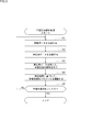
- This process is started, for example, when the learning process of the learning model is started by the learning unit 312.
- step S1 the feature data generation unit 321 generates feature data.
- the feature data generation unit 321 calculates the variance indicating the degree of dispersion of the pixel values of the feature map by the following equation (1).
- the var of the equation (1) shows the dispersion of the pixel values of the feature map.
- I indicates the value obtained by subtracting 1 from the number of pixels in the column direction (vertical direction) of the feature map
- J indicates the value obtained by subtracting 1 from the number of pixels in the row direction (horizontal direction) of the feature map.
- a i, j indicates the pixel value of the coordinates (i, j) of the feature map.
- mean represents the average of the pixel values of the feature map and is calculated by the equation (2).
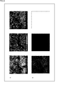
- a in FIG. 6 shows an example of a feature map having a large dispersion of pixel values
- B in FIG. 6 shows an example of a feature map having a small dispersion of pixel values.
- a feature map with a larger dispersion of pixel values is more likely to capture the features of a captured image
- a feature map with a smaller dispersion of pixel values is less likely to capture the features of a captured image.
- the learning unit 312 performs the learning process of the object recognition model 201 each time the teacher data is input, and also performs a plurality of feature maps generated from the captured images included in the teacher data in the layer 221 of the object recognition model 201. Is supplied to the feature data generation unit 321.
- the feature data generation unit 321 calculates the variance of the pixel values of each feature map, and supplies the feature data indicating the calculated variance to the analysis data generation unit 322.
- step S2 the analysis data generation unit 322 generates analysis data.
- FIG. 7 shows an example in which the feature maps generated in the layer 221 of the object recognition model 201 are arranged in a row.
- the analysis data generation unit 322 compresses the amount of information by arranging the feature data of the plurality of feature maps generated from the plurality of captured images in the layer 221 in a predetermined order, and performs one analysis. Generate data.
- FIG. 8 shows an example in which the feature maps generated from 200 captured images are arranged two-dimensionally in the layer 221 of the object recognition model 201.
- the vertical columns in the figure indicate the number of the captured image, and the horizontal row indicates the number of the feature map.
- 512 feature maps generated from each captured image are arranged in numerical order from left to right.
- 512 feature maps generated from the first captured image are arranged in numerical order from left to right.
- the analysis data generation unit 322 generates 512 feature data (dispersion of each feature map) based on 512 feature maps generated from each captured image for each captured image in the order of the corresponding feature map numbers. By arranging them, a 512-dimensional vector (hereinafter referred to as a dispersion vector) is generated. For example, for the captured image 1 of FIG. 8, one dispersion vector having 512 feature data as elements based on the feature map 1 to the feature map 512 generated from the captured image 1 is generated. Then, the dispersion vector 1 to the dispersion vector 200 for the captured image 1 to the captured image 200 are generated.
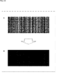
- FIG. 9 shows a dispersion vector and an example of imaging the dispersion vector.
- the image of the dispersion vector is an image in which pixels showing colors corresponding to the values of each element (feature data) of the dispersion vector are arranged in order in the horizontal direction. For example, the pixel color is set to become red as the pixel value of the feature data (dispersion of the feature map) decreases, and to become blue as the value of the feature data (dispersion of the feature map) of the pixel value increases. ing.
- the image of the dispersion vector is actually a color image, but here it is shown by a grayscale image.
- the analysis data generation unit 322 generates analysis data composed of image data in which the element (feature data) of the dispersion vector of each captured image is a pixel.
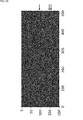
- FIG. 10 shows an example of imaging the analysis data generated based on the feature map of FIG.
- the pixel color of the analysis data becomes red as the value of the feature data which is the pixel value becomes smaller, and becomes blue as the value of the feature data which is the pixel value becomes larger, as in the image of the dispersion vector of FIG. It is set to be.
- the image of the analysis data is actually a color image, it is shown here by a grayscale image.
- the x-axis direction (horizontal direction) of the analysis data indicates the number of the feature map
- the y-axis direction vertical direction
- the feature data of each feature map is arranged in the same order as the feature map of FIG. That is, in the x-axis direction (horizontal direction) of the analysis data, 512 feature data based on 512 feature maps generated from the same captured image are arranged in numerical order of the feature maps. Further, in the y-axis direction of the analysis data, feature data based on feature maps (with the same number) corresponding to each other of different captured images are arranged in the order of the photographed images.
- the white circles in the figure indicate the positions of the pixels corresponding to the 200th feature map 200 of the 100th captured image 100.
- the analysis data generation unit 322 supplies the generated analysis data to the analysis unit 323 and the output control unit 314.
- the output unit 315 displays the analysis data under the control of the output control unit 314, for example.
- step S3 the analysis unit 323 analyzes the learning situation using the analysis data.
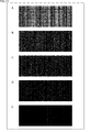
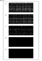
- FIG. 11 shows an example of how the analysis data changes as the learning progresses.
- the analysis data of A to E in FIG. 11 are arranged in the order of learning progress, the analysis data of A in FIG. 11 is the oldest, and the analysis data of E in FIG. 11 is the newest.
- the horizontal line is, for example, a row in the x-axis direction in which pixels having a pixel value (value of feature data) equal to or greater than a predetermined threshold value are present.
- the vertical line is, for example, a column in the y-axis direction in which pixels having a pixel value (value of feature data) of a predetermined threshold value or more are present.
- the number of horizontal lines and vertical lines is counted for each row in the x-axis direction and a column in the y-axis direction of the analysis data. That is, even if a plurality of horizontal lines or a plurality of vertical lines are adjacent to each other and look like one line, they are counted as different lines.
- the ideal state is that there are no horizontal lines in the analysis data and the vertical lines converge within a predetermined range, and the learning model is properly trained. is there.
- the highly dispersed feature map is a feature map that is likely to contribute to the recognition of an object in the learning model by extracting the features of the captured image regardless of the content of the captured image.
- the low-dispersion feature map is a feature map that does not extract the features of the captured image regardless of the content of the captured image and is unlikely to contribute to the recognition of the object of the learning model.
- the highly dispersed feature map does not always contribute to the recognition of the object (for example, the vehicle) to be recognized by the learning model, and may contribute to the recognition of an object other than the recognition target if the learning is not sufficient. .. However, if the learning model is properly trained, the highly distributed feature map becomes a feature map that contributes to the recognition of the object to be recognized by the learning model.
- regularization processing is performed in order to suppress overfitting and reduce the weight of the neural network.
- the types of features extracted from the captured image are narrowed down to some extent. That is, the number of feature maps that can extract features of captured images, that is, highly dispersed feature maps, is narrowed down to some extent.
- the number of vertical lines of the analysis data converges within a predetermined range, which is an ideal state in which regularization is normally performed.
- the number of vertical lines of the analysis data decreases too much or becomes 0 because the regularization is too strong and the characteristics of the captured image are sufficient. It is in a state where it cannot be extracted. Further, as shown in FIG. 15, the reason why the number of vertical lines of the analysis data does not decrease even if the learning progresses is that the regularization is too weak and the types of features to be extracted from the captured image are not completely narrowed down. Is.
- the analysis unit 323 determines that the regularization of the learning process is normally performed. On the other hand, the analysis unit 323 determines that the regularization is too weak when the number of vertical lines of the analysis data converges to a value exceeding a predetermined range or when the number of vertical lines does not converge. Further, the analysis unit 323 determines that the regularization is too strong when the number of vertical lines of the analysis data converges to a value less than a predetermined range.
- the number of vertical lines of the analysis data decreases and converges as the learning progresses.
- the number of vertical lines of the analysis data converges with a large value as compared with the case where the regularization process is not performed, but the learning process is based on the number of vertical lines as in the case where the regularization process is performed. It is possible to determine whether or not is performed normally.
- a horizontal line appears in the line corresponding to the highly dispersed captured image of the analysis data.
- a captured image hereinafter referred to as a low-dispersion captured image
- a horizontal line does not appear in the line corresponding to the low-dispersion captured image of the analysis data.
- the analysis unit 323 determines that the learning process is normally performed. On the other hand, the analysis unit 323 determines that the learning process is not normally performed when the number of horizontal lines of the analysis data converges to a value equal to or more than a predetermined threshold value or when the number of horizontal lines does not converge.
- the analysis unit 323 supplies data indicating the analysis result of the learning situation to the parameter setting unit 324.
- step S4 the parameter setting unit 324 adjusts the parameters of the learning process based on the analysis result. For example, when the analysis unit 323 determines that the regularization is too strong, the parameter setting unit 324 makes the value of the regularization parameter used in the regularization process smaller than the current value. On the other hand, the parameter setting unit 324 increases the value of the regularization parameter to a larger value than the current value when the analysis unit 323 determines that the regularization is too weak. The larger the value of the regularization parameter, the stronger the regularization, and the smaller the value of the regularization parameter, the weaker the regularization. The parameter setting unit 324 supplies the learning unit 312 with data indicating the adjusted regularization parameter.
- the learning unit 312 sets the value of the regularization parameter to the value set by the parameter setting unit 324. As a result, regularization can be performed more normally in the learning process of the learning model.
- the user may adjust the learning parameters such as the regularization parameter by referring to the analysis data displayed in the output unit 315.
- step S5 the learning situation analysis unit 313 determines whether or not the learning process by the learning unit 312 is completed. If it is determined that the learning process has not been completed, the process returns to step S1. After that, in step S5, the processes of steps S1 to S5 are repeatedly executed until it is determined that the learning process is completed.
- step S5 if it is determined in step S5 that the learning process has been completed, the learning situation analysis process ends.
- the learning status of the learning model by the learning unit 312 can be analyzed. Further, based on the analysis result, the parameters of the learning process can be appropriately set to improve the learning accuracy and shorten the learning time.
- the user can easily recognize the learning status of the learning model by visually recognizing the analysis data.
- the image data used by the learning model to be analyzed by the information processing device 301 The type and the type of the object to be recognized are not particularly limited.
- FIG. 16 shows a configuration example of the object recognition model 401, which is a learning model for which the learning situation is analyzed.
- the object recognition model 401 is used, for example, in the vehicle exterior information detection unit 141 of the vehicle control system 100 of FIG.
- the object recognition model 401 includes, for example, a captured image (for example, captured image 402) that is image data captured in front of the vehicle 10 and a millimeter wave image output from a millimeter wave radar that monitors the front of the vehicle 10 (for example, a captured image 402).
- a millimeter wave image 403 is input as input data.
- the millimeter wave image is, for example, image data showing the distribution of the intensity of the received signal of the millimeter wave radar reflected by the object in front of the vehicle 10 from a bird's-eye view.
- the object recognition model 401 performs recognition processing of the vehicle in front of the vehicle 10 based on the captured image and the millimeter wave image, and outputs an output image (for example, output image 404) which is image data showing the recognition result.
- Output as.
- the object recognition model 401 is a learning model using DSSD (Deconvolutional Single Shot Detector).
- the object recognition model 401 includes a feature extraction layer 411, a feature extraction layer 412, a coupling portion 413, and a prediction layer 414.
- the feature extraction layer 411 has the same configuration as the feature extraction layer 211 of the object recognition model 201 of FIG. Each layer of the feature extraction layer 411 generates a feature map showing the features of the captured image by a predetermined calculation, and supplies the feature map to the next layer. Further, a part of the feature extraction layer 411 supplies the feature map to the connecting portion 413.
- the feature extraction layer 412 has a hierarchical structure, and each layer is composed of a convolution layer, a pooling layer, and the like. Each layer of the feature extraction layer 412 generates a feature map showing the features of the millimeter-wave image by a predetermined calculation, and supplies the feature map to the next layer. Further, a part of the feature extraction layer 412 supplies the feature map to the connecting portion 413. Further, the feature extraction layer 412 converts the millimeter wave image into an image having the same camera coordinate system as the captured image.
- the connecting unit 413 combines the feature maps output from the corresponding layers of the feature extraction layer 411 and the feature extraction layer 412, and supplies the feature maps to the prediction layer 414.
- the prediction layer 414 performs recognition processing of the vehicle in front of the vehicle 10 based on the feature map supplied from the joint portion 413.
- the prediction layer 414 outputs an output image showing the recognition result of the vehicle.
- the object recognition model 401 is divided into a camera network 421, a millimeter wave radar network 422, and a coupling network 423.
- the camera network 421 includes the first half of the feature extraction layer 411 that generates a feature map that is not to be combined from the captured image.
- the millimeter-wave radar network 422 includes the first half of the feature extraction layer 412, which generates a feature map that is not to be combined from a millimeter-wave image.
- connection network 423 includes the latter half of the feature extraction layer 411 that generates the feature map to be combined, the latter half of the feature extraction layer 412 that generates the feature map to be combined, the connection portion 413, and the prediction layer 414. Including.
- the learning situation of the object recognition model 401 was analyzed by the learning situation analysis process described above with reference to FIG. Specifically, the feature map generated and output in the layer 431 which is the intermediate layer of the feature extraction layer 411 surrounded by the thick frame in FIG. 16 and the layer 432 which is the intermediate layer of the feature extraction layer 412.
- the feature map generated and output in was analyzed.
- the feature map generated in the layer 431 is the largest feature map among the feature maps of the feature extraction layer 411 used for the recognition process of the prediction layer 414.
- the feature map generated in the layer 432 is the largest feature map among the feature maps of the feature extraction layer 412 used for the recognition process of the prediction layer 414.
- the analysis data based on the feature map generated in the feature map layer 432 of the feature extraction layer 412 remained without disappearing even if the learning process proceeded, as shown in A to E of FIG. That is, it was found that in the feature extraction layer 412, learning was not properly performed and the features of the millimeter wave image were not properly extracted.
- the analysis data of A to E in FIG. 17 are arranged in the order of progress of learning, as in A to E of FIG.
- FIG. 18 is an enlarged view of the analysis data of E in FIG.
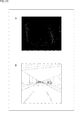
- FIGS. 19 to 21 schematically show millimeter-wave images and captured images corresponding to the rows in which the horizontal lines of the analysis data appear, which are indicated by the arrows in FIG. 19 to 21A are converted millimeter-wave images into grayscale images, and FIGS. 19 to 21B are diagrams of captured images.
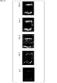
- FIG. 22 shows an example of a feature map of the row in which the horizontal line of the analysis data appears.
- the millimeter-wave image 501 is obtained by converting the millimeter-wave image of the line in which the horizontal line of the analysis data appears into a grayscale image, and the feature map 502-1 to the feature map 502-4 are from the millimeter-wave image 501. It is part of the generated feature map.
- the pixel values change significantly near the left and right edges in front of the vehicle 10.
- the feature map generated from the millimeter wave image features corresponding to the left and right walls in front of the vehicle, not the vehicle in front of the vehicle 10, can be easily extracted.
- the feature extraction layer 412 may be more suitable for recognizing the left and right walls than the vehicle in front of the vehicle 10.
- the feature data used for the analysis data is not limited to the dispersion of the pixel values of the feature map described above, and other numerical values representing the features of the feature map can be used.
- the norm of the feature map calculated by the following equation (3) may be used for the feature data.
- Equation (3) indicates the norm of the feature map.
- n and m indicate arbitrary numbers. Other symbols are the same as those in the above equation (1).
- the norm of the feature map increases as the degree of dispersion of the pixel values of each pixel with respect to the average value of the pixel values of the feature map increases, and decreases as the degree of dispersion of the pixel values of each pixel with respect to the average value of the pixel values of the feature map decreases. Become. Therefore, the norm of the feature map indicates how the pixel values of the feature map are scattered.
- the frequency distribution of the pixel values of the feature map may be used for the feature data.
- FIG. 23 shows an example of a histogram (frequency distribution) of pixel values of the feature map.
- the horizontal axis shows the class based on the pixel value of the feature map. That is, the pixel values of the feature map are classified into a plurality of classes.
- the vertical axis shows the frequency. That is, the pixel value indicates the number of pixels of the feature map belonging to each class.
- the analysis data shown in FIG. 24 is generated based on the plurality of feature maps generated from the plurality of input images (for example, the above-mentioned captured image or millimeter wave image).
- the analysis data 521 of FIG. 24 is three-dimensional data in which the two-dimensional frequency map 522-1 to the frequency map 522-m generated for each class of the histogram are arranged in the z-axis direction (depth direction).
- the x-axis direction (horizontal direction) of the frequency map 522-1 indicates the number of the feature map
- the y-axis direction indicates the number of the input image
- the frequencies of the first class of the histogram of the feature map of each input image are arranged in the x-axis direction (horizontal direction) in the order of the corresponding feature map numbers. Further, the frequencies corresponding to the feature maps having the same numbers of different input images are arranged in the y-axis direction (vertical direction) in the order of the numbers of the corresponding input images.
- the frequency map 522-1 to the frequency map 522-m can be used for analyzing the learning situation based on the vertical and horizontal lines, respectively, as in the above-mentioned two-dimensional analysis data. Further, for example, the analysis data 521 can be used for analyzing the learning situation based on the line in the z-axis direction.
- the analysis data including the extracted feature data is generated.
- the feature data is the dispersion of the pixel values of the feature map
- the feature data whose value is equal to or larger than a predetermined threshold is extracted from the feature data based on a plurality of feature maps generated from one image data.
- Analysis data including feature data may be generated.
- analysis data may be generated for one or more image data based on a plurality of feature maps generated in different layers of the neural network.
- three-dimensional analysis data is generated by stacking the feature data of the feature map generated in each layer in two dimensions in the x-axis direction and the y-axis direction for each layer in the z-axis direction. You may try to do it. That is, in this analysis data, the feature data of the feature maps generated in the same layer are arranged in the x-axis direction and the y-axis direction, and the feature data of the feature maps generated in different layers are arranged in the z-axis direction. Lined up.
- the learning situation analysis process can be performed after the learning process is completed.
- the feature map generated during the learning process may be accumulated, and analysis data may be generated based on the feature map accumulated after the learning process to analyze the learning situation.
- the learning model to be analyzed in the learning process is not limited to the above-mentioned example, and the entire learning model using the neural network can be targeted.
- a recognition model that recognizes an object other than a vehicle and a recognition model that recognizes a plurality of objects including a vehicle are also targeted.
- learning models whose input data is other than image data are also targeted.
- a voice recognition model that uses voice data as input data, a sentence analysis model that uses sentence data as input data, and the like are also targeted.
- FIG. 25 is a block diagram showing a configuration example of computer hardware that executes the above-mentioned series of processes programmatically.
- the CPU Central Processing Unit
- ROM Read Only Memory
- RAM Random Access Memory
- An input / output interface 1005 is further connected to the bus 1004.
- An input unit 1006, an output unit 1007, a recording unit 1008, a communication unit 1009, and a drive 1010 are connected to the input / output interface 1005.
- the input unit 1006 includes an input switch, a button, a microphone, an image sensor, and the like.
- the output unit 1007 includes a display, a speaker, and the like.
- the recording unit 1008 includes a hard disk, a non-volatile memory, and the like.
- the communication unit 1009 includes a network interface and the like.
- the drive 1010 drives a removable medium 1011 such as a magnetic disk, an optical disk, a magneto-optical disk, or a semiconductor memory.
- the CPU 1001 loads and executes the program recorded in the recording unit 1008 into the RAM 1003 via the input / output interface 1005 and the bus 1004, as described above. A series of processing is performed.
- the program executed by the computer 1000 can be recorded and provided on the removable media 1011 as a package media or the like, for example. Programs can also be provided via wired or wireless transmission media such as local area networks, the Internet, and digital satellite broadcasting.
- the program can be installed in the recording unit 1008 via the input / output interface 1005 by mounting the removable media 1011 in the drive 1010.
- the program can be received by the communication unit 1009 and installed in the recording unit 1008 via a wired or wireless transmission medium.
- the program can be installed in advance in the ROM 1002 or the recording unit 1008.
- the program executed by the computer may be a program in which processing is performed in chronological order in the order described in this specification, or in parallel or at a necessary timing such as when a call is made. It may be a program in which processing is performed.
- the system means a set of a plurality of components (devices, modules (parts), etc.), and it does not matter whether all the components are in the same housing. Therefore, a plurality of devices housed in separate housings and connected via a network, and a device in which a plurality of modules are housed in one housing are both systems. ..
- the embodiment of the present technology is not limited to the above-described embodiment, and various changes can be made without departing from the gist of the present technology.
- this technology can have a cloud computing configuration in which one function is shared by a plurality of devices via a network and processed jointly.
- each step described in the above flowchart can be executed by one device or shared by a plurality of devices.
- one step includes a plurality of processes
- the plurality of processes included in the one step can be executed by one device or shared by a plurality of devices.
- the present technology can also have the following configurations.
- a feature data generation step that generates feature data that numerically represents the features of the feature map generated from the input data in a model using a neural network, and a feature data generation step.
- An information processing method including an analysis data generation step for generating analysis data based on the feature data of a plurality of the feature maps.
- (3) In the analysis data the feature data of a plurality of the feature maps generated from the plurality of input data are arranged in a predetermined layer of the model that generates a plurality of the feature maps from one input data.
- the feature data of a plurality of the feature maps generated from the same input data are arranged in the first direction of the analysis data, and different in the second direction orthogonal to the first direction.
- the information processing method according to (3) above wherein the feature data of the feature map corresponding to each other of the input data are arranged.
- the information processing method according to (6) above further including a parameter setting step of setting parameters for learning the model based on the analysis result of the learning situation of the model.
- the information processing method according to (7) above wherein in the parameter setting step, regularization parameters for learning the model are set based on the number of lines in the second direction of the analysis data.
- the feature data shows the frequency distribution of the pixel values of the feature map.
- the information processing method according to (3) wherein in the analysis data, the feature data of a plurality of the feature maps generated from the plurality of input data in the hierarchy of the model are arranged three-dimensionally.
- the input data is image data and The information processing method according to any one of (1) to (9) above, wherein the model performs object recognition processing.
- the input data is image data representing the distribution of the intensity of the received signal of the millimeter wave radar by a bird's-eye view.
- the model converts the image data into an image of a camera coordinate system.
- the analysis data includes the feature data satisfying a predetermined condition among the feature data of the plurality of feature maps.
- a feature data generation step that generates feature data that numerically represents the features of the feature map generated from the input data in a model using a neural network, and a feature data generation step.
- a program for causing a computer to execute a process including an analysis data generation step for generating analysis data in which the feature data of a plurality of the feature maps are arranged.
- a feature data generator that generates feature data that numerically represents the features of the feature map generated from the input data in a model using a neural network.
- An information processing device including an analysis data generation unit that generates analysis data in which the feature data of a plurality of the feature maps are arranged.
- 10 vehicles 100 vehicle control system, 141 external information detection unit, 201 object recognition model, 211 feature extraction layer, 221 hierarchy, 301 information processing device, 312 learning unit, 313 learning situation analysis unit, 321 feature data generation unit, 322 analysis Data generation unit, 323 analysis unit, 324 parameter setting unit, 401 object recognition model 411,412 feature extraction layer, 421 camera network, 422 millimeter-wave radar network, 423 coupling network, 431,432 hierarchy
Landscapes
- Engineering & Computer Science (AREA)
- Theoretical Computer Science (AREA)
- Physics & Mathematics (AREA)
- General Physics & Mathematics (AREA)
- Evolutionary Computation (AREA)
- Artificial Intelligence (AREA)
- Health & Medical Sciences (AREA)
- General Health & Medical Sciences (AREA)
- Software Systems (AREA)
- Computing Systems (AREA)
- Data Mining & Analysis (AREA)
- Multimedia (AREA)
- Life Sciences & Earth Sciences (AREA)
- General Engineering & Computer Science (AREA)
- Computational Linguistics (AREA)
- Molecular Biology (AREA)
- Biophysics (AREA)
- Mathematical Physics (AREA)
- Biomedical Technology (AREA)
- Computer Vision & Pattern Recognition (AREA)
- Medical Informatics (AREA)
- Databases & Information Systems (AREA)
- Remote Sensing (AREA)
- Radar, Positioning & Navigation (AREA)
- Evolutionary Biology (AREA)
- Bioinformatics & Computational Biology (AREA)
- Bioinformatics & Cheminformatics (AREA)
- Electromagnetism (AREA)
- Computer Networks & Wireless Communication (AREA)
- Traffic Control Systems (AREA)
- Image Analysis (AREA)
Abstract
Description
1.実施の形態
2.学習状況の解析事例
3.変形例
4.その他
まず、図1乃至図15を参照して、本技術の実施の形態について説明する。
図2は、物体認識モデル201の構成例を示している。物体認識モデル201は、例えば、図1の車両制御システム100の車外情報検出部141に用いられる。
図4は、図2の物体認識モデル201等のニューラルネットワークを用いたモデル(以下、学習モデルと称する)の学習に用いられる情報処理装置301の構成例を示している。
次に、図5のフローチャートを参照して、情報処理装置301により実行される学習状況解析処理について説明する。

次に、図16乃至図22を参照して、図4の情報処理装置301を用いて学習モデルの学習状況を解析した事例について説明する。
図16は、学習状況の解析を行う対象となった学習モデルである物体認識モデル401の構成例を示している。物体認識モデル401は、例えば、図1の車両制御システム100の車外情報検出部141に用いられる。
以下、上述した本技術の実施の形態の変形例について説明する。

<コンピュータの構成例>
上述した一連の処理は、ハードウェアにより実行することもできるし、ソフトウェアにより実行することもできる。一連の処理をソフトウェアにより実行する場合には、そのソフトウェアを構成するプログラムが、コンピュータにインストールされる。ここで、コンピュータには、専用のハードウェアに組み込まれているコンピュータや、各種のプログラムをインストールすることで、各種の機能を実行することが可能な、例えば汎用のパーソナルコンピュータなどが含まれる。
本技術は、以下のような構成をとることもできる。
ニューラルネットワークを用いたモデルにおいて入力データから生成される特徴マップの特徴を数値で表す特徴データを生成する特徴データ生成ステップと、
複数の前記特徴マップの前記特徴データに基づく解析用データを生成する解析用データ生成ステップと
を含む情報処理方法。
(2)
前記解析用データには、複数の前記特徴マップの前記特徴データが並べられている
前記(1)に記載の情報処理方法。
(3)
前記解析用データには、1つの前記入力データから複数の前記特徴マップを生成する前記モデルの所定の階層において複数の前記入力データから生成された複数の前記特徴マップの前記特徴データが並べられている
前記(2)に記載の情報処理方法。
(4)
前記解析用データの第1の方向には、同じ前記入力データから生成された複数の前記特徴マップの前記特徴データが並べられ、前記第1の方向と直交する第2の方向には、異なる前記入力データの互いに対応する前記特徴マップの前記特徴データが並べられている
前記(3)に記載の情報処理方法。
(5)
前記特徴データは、前記特徴マップの画素値の散らばり具合を示す
前記(4)に記載の情報処理方法。
(6)
前記解析用データの前記第1の方向の線及び前記第2の方向の線に基づいて、前記モデルの学習状況の解析を行う解析ステップを
さらに含む前記(5)に記載の情報処理方法。
(7)
前記モデルの学習状況の解析結果に基づいて、前記モデルの学習用のパラメータを設定するパラメータ設定ステップを
さらに含む前記(6)に記載の情報処理方法。
(8)
前記パラメータ設定ステップにおいて、前記解析用データの前記第2の方向の線の数に基づいて、前記モデルの学習用の正則化パラメータが設定される
前記(7)に記載の情報処理方法。
(9)
前記特徴データは、前記特徴マップの画素値の度数分布を示し、
前記解析用データには、前記モデルの前記階層において複数の前記入力データから生成された複数の前記特徴マップの前記特徴データが3次元に並べられている
前記(3)に記載の情報処理方法。
(10)
前記入力データは、画像データであり、
前記モデルは、物体の認識処理を行う
前記(1)乃至(9)のいずれかに記載の情報処理方法。
(11)
前記モデルは、車両の認識処理を行う
前記(10)に記載の情報処理方法。
(12)
前記入力データは、ミリ波レーダの受信信号の強度の分布を鳥瞰図により表す画像データである
前記(11)に記載の情報処理方法。
(13)
前記モデルは、前記画像データをカメラ座標系の画像に変換する
前記(12)に記載の情報処理方法。
(14)
前記解析用データは、複数の前記特徴マップの前記特徴データのうち所定の条件を満たす前記特徴データを含む
前記(1)に記載の情報処理方法。
(15)
ニューラルネットワークを用いたモデルにおいて入力データから生成される特徴マップの特徴を数値で表す特徴データを生成する特徴データ生成ステップと、
複数の前記特徴マップの前記特徴データを並べた解析用データを生成する解析用データ生成ステップと
を含む処理をコンピュータに実行させるためのプログラム。
(16)
ニューラルネットワークを用いたモデルにおいて入力データから生成される特徴マップの特徴を数値で表す特徴データを生成する特徴データ生成部と、
複数の前記特徴マップの前記特徴データを並べた解析用データを生成する解析用データ生成部と
を備える情報処理装置。
Claims (16)
- ニューラルネットワークを用いたモデルにおいて入力データから生成される特徴マップの特徴を数値で表す特徴データを生成する特徴データ生成ステップと、
複数の前記特徴マップの前記特徴データに基づく解析用データを生成する解析用データ生成ステップと
を含む情報処理方法。 - 前記解析用データには、複数の前記特徴マップの前記特徴データが並べられている
請求項1に記載の情報処理方法。 - 前記解析用データには、1つの前記入力データから複数の前記特徴マップを生成する前記モデルの所定の階層において複数の前記入力データから生成された複数の前記特徴マップの前記特徴データが並べられている
請求項2に記載の情報処理方法。 - 前記解析用データの第1の方向には、同じ前記入力データから生成された複数の前記特徴マップの前記特徴データが並べられ、前記第1の方向と直交する第2の方向には、異なる前記入力データの互いに対応する前記特徴マップの前記特徴データが並べられている
請求項3に記載の情報処理方法。 - 前記特徴データは、前記特徴マップの画素値の散らばり具合を示す
請求項4に記載の情報処理方法。 - 前記解析用データの前記第1の方向の線及び前記第2の方向の線に基づいて、前記モデルの学習状況の解析を行う解析ステップを
さらに含む請求項5に記載の情報処理方法。 - 前記モデルの学習状況の解析結果に基づいて、前記モデルの学習用のパラメータを設定するパラメータ設定ステップを
さらに含む請求項6に記載の情報処理方法。 - 前記パラメータ設定ステップにおいて、前記解析用データの前記第2の方向の線の数に基づいて、前記モデルの学習用の正則化パラメータが設定される
請求項7に記載の情報処理方法。 - 前記特徴データは、前記特徴マップの画素値の度数分布を示し、
前記解析用データには、前記モデルの前記階層において複数の前記入力データから生成された複数の前記特徴マップの前記特徴データが3次元に並べられている
請求項3に記載の情報処理方法。 - 前記入力データは、画像データであり、
前記モデルは、物体の認識処理を行う
請求項1に記載の情報処理方法。 - 前記モデルは、車両の認識処理を行う
請求項10に記載の情報処理方法。 - 前記入力データは、ミリ波レーダの受信信号の強度の分布を鳥瞰図により表す画像データである
請求項11に記載の情報処理方法。 - 前記モデルは、前記画像データをカメラ座標系の画像に変換する
請求項12に記載の情報処理方法。 - 前記解析用データは、複数の前記特徴マップの前記特徴データのうち所定の条件を満たす前記特徴データを含む
請求項1に記載の情報処理方法。 - ニューラルネットワークを用いたモデルにおいて入力データから生成される特徴マップの特徴を数値で表す特徴データを生成する特徴データ生成ステップと、
複数の前記特徴マップの前記特徴データに基づく解析用データを生成する解析用データ生成ステップと
を含む処理をコンピュータに実行させるためのプログラム。 - ニューラルネットワークを用いたモデルにおいて入力データから生成される特徴マップの特徴を数値で表す特徴データを生成する特徴データ生成部と、
複数の前記特徴マップの前記特徴データに基づく解析用データを生成する解析用データ生成部と
を備える情報処理装置。
Priority Applications (7)
| Application Number | Priority Date | Filing Date | Title |
|---|---|---|---|
| MX2021011219A MX2021011219A (es) | 2019-03-29 | 2020-03-17 | Metodo de procesamiento de informacion, programa y dispositivo de procesamiento de informacion. |
| KR1020217026682A KR20210142604A (ko) | 2019-03-29 | 2020-03-17 | 정보 처리 방법, 프로그램 및 정보 처리 장치 |
| EP20784531.4A EP3951663B1 (en) | 2019-03-29 | 2020-03-17 | Information processing method, program, and information processing device |
| US17/442,075 US12243320B2 (en) | 2019-03-29 | 2020-03-17 | Information processing method, program, and information processing apparatus |
| ES20784531T ES3010476T3 (en) | 2019-03-29 | 2020-03-17 | Information processing method, program, and information processing device |
| JP2021511392A JP7487178B2 (ja) | 2019-03-29 | 2020-03-17 | 情報処理方法、プログラム、及び、情報処理装置 |
| CA3134088A CA3134088A1 (en) | 2019-03-29 | 2020-03-17 | Information processing method, program, and information processing apparatus |
Applications Claiming Priority (2)
| Application Number | Priority Date | Filing Date | Title |
|---|---|---|---|
| JP2019065378 | 2019-03-29 | ||
| JP2019-065378 | 2019-03-29 |
Publications (1)
| Publication Number | Publication Date |
|---|---|
| WO2020203241A1 true WO2020203241A1 (ja) | 2020-10-08 |
Family
ID=72668318
Family Applications (1)
| Application Number | Title | Priority Date | Filing Date |
|---|---|---|---|
| PCT/JP2020/011601 Ceased WO2020203241A1 (ja) | 2019-03-29 | 2020-03-17 | 情報処理方法、プログラム、及び、情報処理装置 |
Country Status (8)
| Country | Link |
|---|---|
| US (1) | US12243320B2 (ja) |
| EP (1) | EP3951663B1 (ja) |
| JP (1) | JP7487178B2 (ja) |
| KR (1) | KR20210142604A (ja) |
| CA (1) | CA3134088A1 (ja) |
| ES (1) | ES3010476T3 (ja) |
| MX (1) | MX2021011219A (ja) |
| WO (1) | WO2020203241A1 (ja) |
Cited By (1)
| Publication number | Priority date | Publication date | Assignee | Title |
|---|---|---|---|---|
| CN114863472A (zh) * | 2022-03-28 | 2022-08-05 | 深圳海翼智新科技有限公司 | 多级行人检测方法、装置和存储介质 |
Families Citing this family (4)
| Publication number | Priority date | Publication date | Assignee | Title |
|---|---|---|---|---|
| US12392628B2 (en) * | 2020-06-30 | 2025-08-19 | Lyft, Inc. | Localization based on multi-collect fusion |
| US12087004B2 (en) | 2020-06-30 | 2024-09-10 | Lyft, Inc. | Multi-collect fusion |
| US12523478B2 (en) | 2022-10-13 | 2026-01-13 | Woven By Toyota, Inc. | Map data compression methods implementing machine learning |
| CN116739437A (zh) * | 2023-07-14 | 2023-09-12 | 鱼快创领智能科技(南京)有限公司 | 一种基于车联网数据的综合运力分级方法 |
Citations (2)
| Publication number | Priority date | Publication date | Assignee | Title |
|---|---|---|---|---|
| JP2018520404A (ja) * | 2015-04-28 | 2018-07-26 | クゥアルコム・インコーポレイテッドQualcomm Incorporated | ニューラルネットワークのためのトレーニング基準としてのフィルタ特異性 |
| WO2018165753A1 (en) * | 2017-03-14 | 2018-09-20 | University Of Manitoba | Structure defect detection using machine learning algorithms |
Family Cites Families (8)
| Publication number | Priority date | Publication date | Assignee | Title |
|---|---|---|---|---|
| JP3058951B2 (ja) | 1991-09-03 | 2000-07-04 | 浜松ホトニクス株式会社 | 画像パターン認識装置 |
| KR102592076B1 (ko) * | 2015-12-14 | 2023-10-19 | 삼성전자주식회사 | 딥러닝 기반 영상 처리 장치 및 방법, 학습 장치 |
| WO2017192889A1 (en) | 2016-05-04 | 2017-11-09 | Intel Corporation | Antenna panel switching and beam indication |
| WO2018212606A1 (ko) | 2017-05-17 | 2018-11-22 | 엘지전자(주) | 무선 통신 시스템에서 하향링크 채널을 수신하는 방법 및 이를 위한 장치 |
| KR102419136B1 (ko) * | 2017-06-15 | 2022-07-08 | 삼성전자주식회사 | 다채널 특징맵을 이용하는 영상 처리 장치 및 방법 |
| US20190026588A1 (en) * | 2017-07-19 | 2019-01-24 | GM Global Technology Operations LLC | Classification methods and systems |
| JP7160040B2 (ja) * | 2017-08-22 | 2022-10-25 | ソニーグループ株式会社 | 信号処理装置、および信号処理方法、プログラム、移動体、並びに、信号処理システム |
| EP3617947B1 (en) * | 2018-08-30 | 2026-04-22 | Nokia Technologies Oy | Apparatus and method for processing image data |
-
2020
- 2020-03-17 KR KR1020217026682A patent/KR20210142604A/ko not_active Withdrawn
- 2020-03-17 MX MX2021011219A patent/MX2021011219A/es unknown
- 2020-03-17 WO PCT/JP2020/011601 patent/WO2020203241A1/ja not_active Ceased
- 2020-03-17 US US17/442,075 patent/US12243320B2/en active Active
- 2020-03-17 ES ES20784531T patent/ES3010476T3/es active Active
- 2020-03-17 CA CA3134088A patent/CA3134088A1/en active Pending
- 2020-03-17 EP EP20784531.4A patent/EP3951663B1/en active Active
- 2020-03-17 JP JP2021511392A patent/JP7487178B2/ja active Active
Patent Citations (2)
| Publication number | Priority date | Publication date | Assignee | Title |
|---|---|---|---|---|
| JP2018520404A (ja) * | 2015-04-28 | 2018-07-26 | クゥアルコム・インコーポレイテッドQualcomm Incorporated | ニューラルネットワークのためのトレーニング基準としてのフィルタ特異性 |
| WO2018165753A1 (en) * | 2017-03-14 | 2018-09-20 | University Of Manitoba | Structure defect detection using machine learning algorithms |
Non-Patent Citations (2)
| Title |
|---|
| MATTHEW D ZEILER; ROB FERGUS: "Visualizing and Understanding Convolutional Networks", EUROPEAN CONFERENCE ON COMPUTER VISION (ECCV), 2014, ECCV, 2014, pages 818 - 833, XP055566692, Retrieved from the Internet <URL:https://cs.nyu.edu/~fergus/papers/zeilerECCV2014.pdf> * |
| See also references of EP3951663A4 * |
Cited By (1)
| Publication number | Priority date | Publication date | Assignee | Title |
|---|---|---|---|---|
| CN114863472A (zh) * | 2022-03-28 | 2022-08-05 | 深圳海翼智新科技有限公司 | 多级行人检测方法、装置和存储介质 |
Also Published As
| Publication number | Publication date |
|---|---|
| MX2021011219A (es) | 2021-10-22 |
| CA3134088A1 (en) | 2020-10-08 |
| EP3951663A1 (en) | 2022-02-09 |
| ES3010476T3 (en) | 2025-04-03 |
| US12243320B2 (en) | 2025-03-04 |
| US20220172484A1 (en) | 2022-06-02 |
| EP3951663B1 (en) | 2024-12-25 |
| KR20210142604A (ko) | 2021-11-25 |
| JP7487178B2 (ja) | 2024-05-20 |
| JPWO2020203241A1 (ja) | 2020-10-08 |
| EP3951663A4 (en) | 2022-05-04 |
Similar Documents
| Publication | Publication Date | Title |
|---|---|---|
| JP7757353B2 (ja) | 情報処理装置、情報処理方法、及び、情報処理システム | |
| US11531354B2 (en) | Image processing apparatus and image processing method | |
| US11450026B2 (en) | Information processing apparatus, information processing method, and mobile object | |
| US12511762B2 (en) | Learning model generation method, information processing device, and information processing system | |
| US20210116930A1 (en) | Information processing apparatus, information processing method, program, and mobile object | |
| JPWO2019077999A1 (ja) | 撮像装置、画像処理装置、及び、画像処理方法 | |
| JP7487178B2 (ja) | 情報処理方法、プログラム、及び、情報処理装置 | |
| JPWO2020116194A1 (ja) | 情報処理装置、情報処理方法、プログラム、移動体制御装置、及び、移動体 | |
| WO2021241189A1 (ja) | 情報処理装置、情報処理方法、およびプログラム | |
| JPWO2019082670A1 (ja) | 情報処理装置、情報処理方法、プログラム、及び、移動体 | |
| JPWO2019188391A1 (ja) | 制御装置、制御方法、並びにプログラム | |
| US20240290108A1 (en) | Information processing apparatus, information processing method, learning apparatus, learning method, and computer program | |
| WO2021193099A1 (ja) | 情報処理装置、情報処理方法、及びプログラム | |
| JPWO2020116204A1 (ja) | 情報処理装置、情報処理方法、プログラム、移動体制御装置、及び、移動体 | |
| US20240257508A1 (en) | Information processing device, information processing method, and program | |
| US20230206596A1 (en) | Information processing device, information processing method, and program | |
| US20230121905A1 (en) | Information processing apparatus, information processing method, and program | |
| WO2021033574A1 (ja) | 情報処理装置、および情報処理方法、並びにプログラム | |
| JP7676407B2 (ja) | 情報処理装置、情報処理方法、及び、プログラム | |
| WO2021145227A1 (ja) | 情報処理装置、情報処理方法、及び、プログラム | |
| US20250172950A1 (en) | Information processing apparatus, information processing method, information processing program, and mobile apparatus | |
| WO2024009829A1 (ja) | 情報処理装置、情報処理方法および車両制御システム | |
| US12633133B2 (en) | Recognition processing device, recognition processing method, and recognition processing system | |
| US20240386724A1 (en) | Recognition processing device, recognition processing method, and recognition processing system | |
| US20250128732A1 (en) | Information processing apparatus, information processing method, and moving apparatus |
Legal Events
| Date | Code | Title | Description |
|---|---|---|---|
| 121 | Ep: the epo has been informed by wipo that ep was designated in this application |
Ref document number: 20784531 Country of ref document: EP Kind code of ref document: A1 |
|
| ENP | Entry into the national phase |
Ref document number: 2021511392 Country of ref document: JP Kind code of ref document: A |
|
| ENP | Entry into the national phase |
Ref document number: 3134088 Country of ref document: CA |
|
| NENP | Non-entry into the national phase |
Ref country code: DE |
|
| ENP | Entry into the national phase |
Ref document number: 2020784531 Country of ref document: EP Effective date: 20211029 |
|
| WWG | Wipo information: grant in national office |
Ref document number: MX/A/2021/011219 Country of ref document: MX |
|
| WWG | Wipo information: grant in national office |
Ref document number: 17442075 Country of ref document: US |
|
| WWW | Wipo information: withdrawn in national office |
Ref document number: 1020217026682 Country of ref document: KR |