WO2020203408A1 - 繰出し容器 - Google Patents
繰出し容器 Download PDFInfo
- Publication number
- WO2020203408A1 WO2020203408A1 PCT/JP2020/012695 JP2020012695W WO2020203408A1 WO 2020203408 A1 WO2020203408 A1 WO 2020203408A1 JP 2020012695 W JP2020012695 W JP 2020012695W WO 2020203408 A1 WO2020203408 A1 WO 2020203408A1
- Authority
- WO
- WIPO (PCT)
- Prior art keywords
- outer cylinder
- lid
- main body
- cylinder
- ring
- Prior art date
- Legal status (The legal status is an assumption and is not a legal conclusion. Google has not performed a legal analysis and makes no representation as to the accuracy of the status listed.)
- Ceased
Links
Images


Classifications
-
- A—HUMAN NECESSITIES
- A45—HAND OR TRAVELLING ARTICLES
- A45D—HAIRDRESSING OR SHAVING EQUIPMENT; EQUIPMENT FOR COSMETICS OR COSMETIC TREATMENTS, e.g. FOR MANICURING OR PEDICURING
- A45D40/00—Casings or accessories specially adapted for storing or handling solid or pasty toiletry or cosmetic substances, e.g. shaving soaps or lipsticks
- A45D40/06—Casings wherein movement of the lipstick or like solid is a screwing movement
-
- B—PERFORMING OPERATIONS; TRANSPORTING
- B65—CONVEYING; PACKING; STORING; HANDLING THIN OR FILAMENTARY MATERIAL
- B65D—CONTAINERS FOR STORAGE OR TRANSPORT OF ARTICLES OR MATERIALS, e.g. BAGS, BARRELS, BOTTLES, BOXES, CANS, CARTONS, CRATES, DRUMS, JARS, TANKS, HOPPERS, FORWARDING CONTAINERS; ACCESSORIES, CLOSURES, OR FITTINGS THEREFOR; PACKAGING ELEMENTS; PACKAGES
- B65D53/00—Sealing or packing elements; Sealings formed by liquid or plastics material
- B65D53/02—Collars or rings
-
- A—HUMAN NECESSITIES
- A45—HAND OR TRAVELLING ARTICLES
- A45D—HAIRDRESSING OR SHAVING EQUIPMENT; EQUIPMENT FOR COSMETICS OR COSMETIC TREATMENTS, e.g. FOR MANICURING OR PEDICURING
- A45D40/00—Casings or accessories specially adapted for storing or handling solid or pasty toiletry or cosmetic substances, e.g. shaving soaps or lipsticks
- A45D2040/0025—Details of lipstick or like casings
-
- B—PERFORMING OPERATIONS; TRANSPORTING
- B65—CONVEYING; PACKING; STORING; HANDLING THIN OR FILAMENTARY MATERIAL
- B65D—CONTAINERS FOR STORAGE OR TRANSPORT OF ARTICLES OR MATERIALS, e.g. BAGS, BARRELS, BOTTLES, BOXES, CANS, CARTONS, CRATES, DRUMS, JARS, TANKS, HOPPERS, FORWARDING CONTAINERS; ACCESSORIES, CLOSURES, OR FITTINGS THEREFOR; PACKAGING ELEMENTS; PACKAGES
- B65D83/00—Containers or packages with special means for dispensing contents
- B65D83/76—Containers or packages with special means for dispensing contents for dispensing fluent contents by means of a piston
Definitions
- the present invention relates to a feeding container, in particular, a feeding container having a main body for accommodating the contents and a lid to be combined with the main body, and configured to feed the contents from the main body. ..
- Patent Document 1 for example, as one of the containers for containing a solid composition such as cosmetics for lips, a bottomed cylindrical main body outer cylinder and the main body outer cylinder are used.
- a middle tool that partially extends from the inside, a middle plate that holds the solid contents and is movably arranged inside the outer cylinder of the main body in the direction of the cylinder axis, and a cylindrical shape with a bottom that is roughly formed outside the main body
- a lid outer cylinder that defines a closed space inside together with the cylinder, a lid inner cylinder arranged inside the lid outer cylinder, and a feeding mechanism that moves the inner plate in the direction of the cylinder axis to feed out the contents from the inner tool.
- a feeding container is known to be equipped with.
- the outer cylinder of the main body, the inner tool and the outer cylinder of the lid are often formed of a metal such as aluminum in order to prevent volatilization of the contents.
- the inner tool has a first portion arranged inside the outer cylinder of the main body and a second portion extending from the open end, that is, the end surface on the open side of the outer cylinder of the main body. The portion of the above is in close contact with the outer cylinder of the main body over the entire circumference at least in part, and the second portion constitutes an annular convex portion adjacent to the open end of the outer cylinder of the main body.
- the lid outer cylinder is configured to define the above-mentioned closed space by setting the open end in contact with the convex portion of the inner tool (closed state).
- the inner cylinder of the lid is often configured to be in close contact with the outer cylinder of the lid over the entire circumference and to prevent the inner tool from coming off.
- lip cosmetics such as lip gloss and solid lipstick
- hydrocarbons such as isododecane and water
- Patent Document 2 It is considered that this kind of solid lip cosmetics, like other lip cosmetics, is put into a delivery container for sale or the like.
- the present invention has been made in view of the above circumstances, and provides a feeding container capable of suppressing a decrease in the contents when containing a content containing a hydrocarbon such as isododecane and water.
- a feeding container capable of suppressing a decrease in the contents when containing a content containing a hydrocarbon such as isododecane and water. The purpose.
- the feeding container according to the present invention
- a metal body outer cylinder formed in a roughly bottomed cylindrical shape, It has a first part arranged inside the outer cylinder of the main body and a second part extending from the open end of the outer cylinder of the main body, and the first part covers at least a part of the outer cylinder of the main body and the entire circumference.
- a cylindrical metal inner tool that is in close contact with each other and whose second portion constitutes an annular convex portion adjacent to the open end of the outer cylinder of the main body.
- An inner plate that holds the solid contents and is movably arranged inside the outer cylinder of the main body in the axial direction.
- a metal lid outer cylinder which is formed in a substantially bottomed cylindrical shape and whose open end surface abuts on the convex portion of the inner tool to define a closed space inside together with the main body outer cylinder.
- a lid inner cylinder arranged inside the lid outer cylinder and at least partly in close contact with the lid outer cylinder over the entire circumference.
- a feeding mechanism that moves the middle plate in the direction of the cylinder axis to feed the contents out of the middle tool, In the feeding container with When the lid outer cylinder is placed at a closed position that defines the closed space by being fitted around the portion on the tip side of the convex portion of the inner tool, the space between the lid outer cylinder and the inner tool is The first O-ring that keeps airtight and the second O-ring that is fitted around the part on the rear end side of the convex part of the inner tool to keep the space between the inner tool and the outer cylinder of the main body airtight. At least one is provided, The cylinder inside the lid is made of polyester elastomer, It is characterized by that.
- the present invention is also preferably applied to a feeding container containing a solid composition containing water and a hydrocarbon as contents.
- a solid composition containing water and a hydrocarbon as contents.
- cosmetics particularly lip cosmetics such as solid lipsticks and lip glosses.
- the present inventor has a problem that the content of cosmetics for lips and the like is remarkably reduced with the passage of time in a conventional feeding container, which is composed of LLDPE (linear low-density polyethylene) and the like. It was found that the inventor of the lid was caused by swelling due to hydrocarbons such as isododecane, which is a constituent component of contents such as cosmetics for lips. That is, when the lid inner cylinder swells, the lid inner cylinder may be distorted toward the inside (cylinder axis side) or the outside in the radial direction.
- LLDPE linear low-density polyethylene
- a gap is formed between the lid inner cylinder and the lid outer cylinder through which water and hydrocarbons, which are volatile components in the contents, can pass. It ends up. Further, when the inner cylinder of the lid swells, the inner cylinder of the lid itself easily permeates the above-mentioned volatile components, particularly hydrocarbons such as isododecane.
- the inner cylinder of the lid is made of a polyester-based elastomer based on the above new findings.
- This polyester-based elastomer has almost no or very little swelling due to hydrocarbons such as isododecane. Therefore, in the feeding container of the present invention, it is possible to prevent the volatile components in the contents from being easily volatilized due to the swelling of the cylinder inside the lid, and it is possible to effectively suppress the reduction of the contents.
- the volatile component permeates the inner cylinder of the lid as described above, or the gap between the inner cylinder of the lid and the outer cylinder of the lid. Even if it passes through the lid and then proceeds toward the open end of the lid outer cylinder, the volatile component is blocked by the first O-ring and prevented from coming out of the lid outer cylinder. Therefore, from this point as well, it is possible to suppress the reduction of the contents.
- the volatile component from the contents held in the inner plate may travel through the gap between the outer cylinder of the main body and the inner tool toward the open end side of the outer cylinder of the main body. ..
- the volatile component advancing in this way can be blocked by the second O-ring. Therefore, it is possible to prevent the volatile component from escaping from the open end of the outer cylinder of the main body to the outside through the above gap, and to suppress the reduction of the contents.
- FIG. 1 A perspective view showing a feeding container according to an embodiment of the present invention.
- FIG. 1 is a perspective view showing the appearance of the feeding container 1 according to the embodiment of the present invention
- FIG. 2 is a side sectional view showing the feeding container 1 cut along a plane including its long axis.
- the feeding container 1 is composed of a main body portion 10 for accommodating the content M and a lid portion 20 combined with the main body portion 10 so as to cover the content M.
- FIG. 1 shows a state in which the lid body portion 20 is not combined with the main body portion 10, that is, a lid open state.
- FIG. 2 shows a state in which the lid body portion 20 is combined with the main body portion 10, that is, a closed lid state.
- the content M is a cosmetic for lips, which is a solid composition containing isododecane, which is a kind of hydrocarbon-based oil, and water.
- the main body 10 is basically a metal main body outer cylinder (skein cylinder) 11 formed in a bottomed cylindrical shape and a bottomless cylindrical spiral fitted to the inner peripheral surface of the main body outer cylinder 11.
- the lid portion 20 is basically a metal lid outer cylinder 21 formed in a bottomed cylindrical shape and a bottomed cylindrical lid inner cylinder 22 fitted to the inner peripheral surface of the lid outer cylinder 21. It is composed of and.
- the main body outer cylinder 11 made of metal is formed by preferably using aluminum as an example.
- the cylinder shaft C of the main body outer cylinder 11 is shown by a alternate long and short dash line.
- the metal main body outer cylinder 11 does not allow hydrocarbon-based oil or water to permeate, unlike isododecane, which will be described later. This point is the same for the metal inner tool 15 and the lid outer cylinder 21 described below.
- the bottomless cylindrical spiral cylinder 12 has a spiral groove engraved on the inner peripheral surface, and is integrated with the outer cylinder 11 of the main body by fitting, for example.
- the middle plate 14 has an accommodating portion 14a for accommodating the contents M on the tip end side, that is, on the side opposite to the bottom portion of the main body outer cylinder 11.
- the spiral cylinder 12 and the rotating cylinder 13 are formed of, for example, polyacetal.
- each of these convex portions 14b passes through the straight groove 13a of the rotary cylinder body 13 and is loosely engaged in the spiral groove of the spiral cylinder body 12. Therefore, when the rotary cylinder 13 is rotated relative to the main body outer cylinder 11, that is, with respect to the spiral cylinder 12, the inner plate 14 linearly moves in the main body outer cylinder 11 in the direction along the cylinder axis C. .. The direction of this linear movement changes according to the direction of the relative rotation.
- the spiral cylinder 12 by rotating the rotating cylinder 13 relative to the spiral cylinder 12, the contents M housed in the accommodating portion 14a of the inner plate 14 can be moved from the rotating cylinder 13 (that is, from the inner tool 15). It can be extended or conversely housed in the rotating cylinder 13.
- the spiral cylinder 12, the rotating cylinder 13 having the straight groove 13a, and the convex portion 14b of the inner plate 14 constitute a feeding mechanism for feeding the contents M from the inner tool 15. ..
- the inner tool 15 is formed by preferably using metal, for example, aluminum.
- the inner tool 15 has a first portion 15a arranged inside the main body outer cylinder 11 and a second portion 15b extending from an open end (open end surface) 11a of the main body outer cylinder 11. ing.
- the first portion 15a is fixed to the inner peripheral surface of the main body outer cylinder 11 by fitting or the like so as to be in close contact with the main body outer cylinder 11 over the entire circumference at least in part.
- the second portion 15b constitutes an annular convex portion 15c adjacent to the open end 11a of the main body outer cylinder 11.
- a holding member 16 is attached to the inside of the first portion 15a to rotatably hold the rotary cylinder 13 while preventing the rotary cylinder 13 from moving in the axial direction.
- the first O-ring 31 is fitted to the portion of the inner tool 15 on the tip side of the convex portion 15c over the entire circumference thereof. Further, a second O-ring 32 is fitted to a portion of the inner tool 15 on the rear end side of the convex portion 15c.
- the above-mentioned “rear end side” means the bottom side of the main body outer cylinder 11, and the “tip side” means the side opposite to the bottom of the main body outer cylinder 11.
- the first O-ring 31 and the second O-ring 32 are made of, for example, nitrile rubber (NBR).
- NBR nitrile rubber
- the metal lid outer cylinder 21 is formed by preferably using aluminum as an example.
- the lid inner cylinder 22 is composed of Hytrel (registered trademark), which is a kind of thermoplastic polyester-based elastomer.
- the lid inner cylinder 22 is in close contact with the inner peripheral surface of the lid outer cylinder 21 in a part in the length direction thereof.
- the lid portion 20 When the lid portion 20 is combined with the main body portion 10 and brought into the closed state, that is, the state shown in FIG. 2, the open end 21a of the lid outer cylinder 21 comes into contact with the convex portion 15c of the inner tool 15, and the lid outer cylinder 21 Defines a closed space S inside together with the main body outer cylinder 11.
- the lid body portion 20 fulfills its original function. That is, the content M that is in the closed space S is isolated from the space outside the lid portion 20, and the volatilization of the components in the content M is prevented.
- the inner tool 15 has a shape having two annular convex portions protruding outward in diameter so as to form a concave portion 15d near the tip thereof.
- the closed state is maintained by engaging the recess 15d while elastically deforming a part of the lid inner cylinder 22. That is, the lid inner cylinder 22 fulfills the function of preventing the lid from coming off from the main body 10. Then, by pulling the lid body portion 20 away from the main body portion 10 with a certain amount of force, the engagement can be disengaged and the lid can be opened.
- the content M is a cosmetic for lips containing isododecane, which is a kind of hydrocarbon-based oil, and water, and these isododecane and water (hereinafter, these are referred to as “volatile components”) can be volatilized. ..
- the above-mentioned hytrel constituting the lid inner cylinder 22 has a high function of blocking the passage of these volatile components. Therefore, it is suppressed that the volatile component passes through the inner cylinder 22 of the lid under the closed state and escapes to the open end 21a side of the outer cylinder 21 of the lid.
- the lid inner cylinder 22 is in close contact with the entire inner peripheral surface of the lid outer cylinder 21 in a part in the length direction thereof, a volatile component is formed between the lid outer cylinder 21 and the lid inner cylinder 22. Is also prevented from coming out to the open end 21a side of the lid outer cylinder 21.
- a first O-ring 31 fitted on the outer periphery of the inner tool 15 is interposed between the inner tool 15 and the lid outer cylinder 21 and between them. Keep it airtight. Therefore, even if the volatile component can escape to the open end 21a side of the lid outer cylinder 21 as described above, the volatile component is blocked by the first O-ring 31 and goes out of the lid portion 20. It does not leak.
- the middle plate 14 shown in FIG. 2 is formed with a hole 14c that acts as an air vent passage when accommodating the contents M in the portion corresponding to the bottom of the accommodating portion 14a.
- the volatile component may pass through the hole 14c and escape to the open end of the inner plate 14, wrap around to the inner tool 15 side, and escape from between the inner tool 15 and the main body outer cylinder 11.
- the second O-ring 32 is fitted to the portion of the inner tool 15 on the rear end side of the convex portion 15c. Since the second O-ring 32 keeps the inner tool 15 and the main body outer cylinder 11 airtight, it is also possible to prevent the formation of a passage of the volatile component between the inner tool 15 and the main body outer cylinder 11.
- each of the 9 samples is numbered 1 to 9 to distinguish them. Each of these sample numbers is indicated by a circled number in FIG.
- AL for the lid material is aluminum
- LLDPE linear low-density polyethylene, which is often used as the lid material in this type of cosmetic delivery container. Shown.
- the horizontal axis shows the elapsed time from the initial state in units of weeks (W), and the horizontal axis shows the weight loss rate of the content M from the initial state.
- the weight loss rate indicates what percentage of the weight was lost from the initial state, for example, -5.00% indicates that the weight was reduced by 5.00% from the initial state. It can be said that the smaller the weight loss rate, the more reliably the volatilization of volatile components is prevented.
- sample 9 which is the feeding container 1 of the above embodiment
- the progress of content weight loss with the passage of time is the slowest, and the content weight loss occurs when 32 weeks have passed from the initial state (hereinafter, this time point is referred to as the final time point).
- the rate is also minimal.
- Sample 8 which differs from this sample only in that there is no second O-ring 32, also showed almost the same content weight loss characteristics as sample 9.
- sample 7 which differs from sample 9 only in that there is no first O-ring 31, the progress of content weight loss is clearly faster than that of sample 9, and the content weight loss rate at the final point is the sample. It is about twice that of 9. From the above, it can be said that if only one of the first O-ring 31 and the second O-ring 32 is provided, it is desirable to provide the first O-ring 31.
- the samples 7 to 9 described above are the feeding containers according to the present invention.
- the content weight loss in the samples 1 to 6 which are the feeding containers outside the present invention will be considered.
- Sample 6 differs from Sample 9 only in that it lacks the first O-ring 31 and the second O-ring 32.
- This sample 6 shows the same content weight loss characteristics as the sample 7, but the content weight loss at each time point is slightly larger than that of the sample 7.
- the sample 5 is different from the sample 9 in that the first O-ring 31 and the second O-ring 32 are absent, and the lid outer cylinder 21 is made of hydrell instead of metal. In this sample 5, the weight loss of the contents at each time point is further larger than that in the above sample 6.
- Samples 2, 3 and 4 differ from the above-mentioned samples 7, 8 and 9 which are the feeding containers according to the present invention, respectively, except that the capillary cylinder 22 is formed of LLDPE instead of Hytrel.
- the content loss was small for a while from the initial state, but in Sample 4, the content loss rapidly accelerated from around 3 weeks, and in Sample 3 from around 10 weeks, and at the final point. Both weight loss rates were greater than in sample 7.
- the lid inner cylinder 22 is formed of LLDPE as in the above 2, 3 and 4, and further, like sample 6, neither the first O-ring 31 nor the second O-ring 32 is provided. ..
- the sample 1 and the above-mentioned sample 2 showed almost the same content weight loss characteristics as each other, and the weight loss rate at the final time point was larger than the weight loss rate of the sample 6.
- the contents weight loss of the samples 8 and 9 which are the feeding containers according to the present invention is very gradual throughout the whole period, and the weight loss rate at the final point is clearly smaller than that of the other samples. Further, the content weight loss of the sample 7 which is the feeding container according to the present invention is more remarkable than that of the samples 8 and 9, but the weight loss rate at the final time point is smaller than that of the samples 1 to 6.
- the feeding container 1 of the embodiment described above contains a cosmetic for lips containing isododecane, which is a kind of hydrocarbon oil, and water as the content M, but the feeding container of the present invention is for lips. It may contain contents other than cosmetics. Examples of contents other than lip cosmetics include concealer and solid glue. The present invention is particularly effective when the content is a solid composition containing water and hydrocarbons.
- the present inventors have described the effect of suppressing the weight loss of the contents of the O-ring made of nitrile rubber (NBR) and the fluororubber (specifically, 3M Company's polyol vulcanization binary) used in the above embodiment. If so, the content blocking effect was compared experimentally.
- the feeding container used in this experiment has basically the same shape as the feeding container 1 of the above embodiment shown in FIG. 2, but as shown in Table 2 below, the filling container 15 is not aluminum but POM (polyacetal). ) Is different.
- the lid outer cylinder 21 and the lid inner cylinder 22 are made of aluminum and hytrel, respectively, as in the above-mentioned samples 6 to 9.
- a feeding container in which both the first O-ring 31 and the second O-ring 32 are made of nitrile rubber (hereinafter, this is referred to as sample N) and the first O-ring 31 are made of fluorine rubber.
- sample F a feeding container in which the second O-ring 32 is made of nitrile rubber was prepared.
Landscapes
- Engineering & Computer Science (AREA)
- Mechanical Engineering (AREA)
- Closures For Containers (AREA)
Abstract
【課題】内容物の減りを抑制できる繰出し容器を得る。 【解決手段】有底円筒状の本体外筒(11)と、本体外筒(11)の内側に配された第1の部分(15a)と本体外筒(11)の開放端(11a)から延出した第2の部分(15b)とを有し、第2の部分(15b)が環状凸部(15c)を構成している円筒状の中具(15)と、内容物(M)を保持する中皿(14)と、有底の円筒状に形成されて、開放端(21a)が凸部(15c)に当接して本体外筒(11)と共に閉空間(S)を画成する蓋体外筒(21)と、蓋体外筒(21)の内側に密接している蓋体内筒(22)と、中皿(14)を筒軸方向に移動させて内容物(M)を中具(15)から繰り出させる繰出し機構とを有する繰出し容器(1)において、蓋体外筒(21)と中具(15)との間を気密に保つ第1のOリング(31)と、中具(15)の凸部(15c)よりも後端側の部分に嵌着されて中具(15)と本体外筒(11)との間を気密に保つ第2のOリング(32)とを設け、蓋体内筒(22)をポリエステル系エラストマーから構成する。
Description
本発明は繰出し容器、特に詳しくは、内容物を収容する本体部とこの本体部に組み合わされる蓋体部とを有し、内容物を本体部から繰り出すように構成された繰出し容器に関するものである。
従来、例えば特許文献1に示されているように、口唇用化粧料等の固形組成物を収容する容器の一つとして、有底の円筒状に形成された本体外筒と、この本体外筒から一部が延出した中具と、固形の内容物を保持して本体外筒の内側に筒軸方向に移動自在に配された中皿と、概略有底の円筒状に形成され本体外筒と共に内部に閉空間を画成する蓋体外筒と、この蓋体外筒の内側に配された蓋体内筒と、中皿を筒軸方向に移動させて内容物を中具から繰り出させる繰出し機構とを備えてなる繰出し容器が知られている。
上述の繰出し容器においては、内容物の揮発を防止する等のために、本体外筒、中具および蓋体外筒はアルミニウム等の金属から形成されることが多い。また中具は多くの場合、本体外筒の内側に配された第1の部分と、該本体外筒の開放端つまり開放側の端面から延出した第2の部分とを有し、第1の部分が少なくとも一部において本体外筒と全周に亘って密接し、第2の部分が本体外筒の開放端に隣接した環状の凸部を構成するものとされる。蓋体外筒は、開放端が上記中具の凸部に当接する状態(閉蓋状態)とすることにより、上述の閉空間を画成するように構成される。また蓋体内筒は多くの場合、少なくとも一部が蓋体外筒と全周に亘って密接し、そして中具に対する抜け止めを果たすように構成される。
他方、リップグロスや固形口紅等の口唇用化粧料として、例えば特許文献2に示されているように、イソドデカン等の炭化水素および水を含むものが知られている。この種の固形の口唇用化粧料も、その他の口唇用化粧料と同様に、繰出し容器に収容した形で販売等に供することが考えられている。
しかし本発明者等の研究によると、イソドデカン等の炭化水素および水を含む固形の口唇用化粧料を、上述したような従来の繰出し容器に収容した場合、本体外筒に蓋体外筒を組み合わせて閉蓋状態としておいても、時間経過に伴って化粧料が著しく減量しやすいことが分かった。
本発明は上記の事情に鑑みてなされたものであり、イソドデカン等の炭化水素および水を含む内容物を収容した際に、その内容物の減りを抑制することができる繰出し容器を提供することを目的とする。
本発明による繰出し容器は、
概略有底の円筒状に形成された金属製の本体外筒と、
本体外筒の内側に配された第1の部分と該本体外筒の開放端から延出した第2の部分とを有し、第1の部分が少なくとも一部において本体外筒と全周に亘って密接し、第2の部分が本体外筒の開放端に隣接した環状の凸部を構成している円筒状の金属製の中具と、
固形の内容物を保持し、本体外筒の内側に筒軸方向に移動自在に配された中皿と、
概略有底の円筒状に形成されて、開放側の端面が上記中具の凸部に当接することにより、本体外筒と共に内部に閉空間を画成する金属製の蓋体外筒と、
蓋体外筒の内側に配されて、少なくとも一部が該蓋体外筒と全周に亘って密接している蓋体内筒と、
中皿を筒軸方向に移動させて内容物を中具から繰り出させる繰出し機構と、
を有する繰出し容器において、
上記中具の凸部よりも先端側の部分の周囲に嵌着されて、蓋体外筒が上記閉空間を画成する閉蓋位置に配されたとき該蓋体外筒と中具との間を気密に保つ第1のOリングと、中具の凸部よりも後端側の部分の周囲に嵌着されて、該中具と本体外筒との間を気密に保つ第2のOリングの少なくとも一方が設けられ、
蓋体内筒がポリエステル系エラストマーから構成されている、
ことを特徴とするものである。
なお上記第1のOリングと第2のOリングは、双方とも設けられるのが望ましい。また本発明は好ましくは、水および炭化水素を含む固形組成物を内容物として収容する繰出し容器に適用される。そのような固形組成物として具体的には化粧料、特に固形口紅やリップグロス等の口唇用化粧料が挙げられる。
本発明者は、従来の繰出し容器において口唇用化粧料等の内容物が時間経過に伴って著しく減量するという問題は、LLDPE(直鎖状低密度ポリエチレン:linear low-density polyethylene)等から構成された蓋体内筒が、口唇用化粧料等の内容物の組成成分であるイソドデカン等の炭化水素によって膨潤することに起因していることを見出した。すなわち、この蓋体内筒が膨潤すると、蓋体内筒は径方向の内側(筒軸側)や外側に向かって歪むことがある。そして、径方向の内側に向かって歪んだ蓋体内筒の部分では、該蓋体内筒と蓋体外筒との間に、内容物中の揮発成分である水や炭化水素を通過させ得る隙間が生じてしまう。また蓋体内筒が膨潤すると、この蓋体内筒自身が上記の揮発成分、特にイソドデカン等の炭化水素を透過させ易くなる。
本発明の繰出し容器においては、上記の新しい知見に基づいて、蓋体内筒がポリエステル系エラストマーから構成されている。このポリエステル系エラストマーは、イソドデカン等の炭化水素によって膨潤することが殆ど無い、あるいは極めて少ないものである。したがって本発明の繰出し容器においては、蓋体内筒の膨潤に起因して内容物中の揮発成分が揮発し易くなることが防止され、内容物の減りを効果的に抑制可能となる。
また本発明の繰出し容器において前述した第1のOリングが設けられている場合は、例え揮発成分が上述のように蓋体内筒を透過したり、蓋体内筒と蓋体外筒との間の隙間を通過したりして、その後に蓋体外筒の開放端に向かって進んだとしても、揮発成分はこの第1のOリングで遮断されて蓋体外筒から抜け出ることが防止される。よってこの点からも、内容物の減りを抑制可能となる。
一方、本体外筒の内部では、中皿に保持されている内容物からの揮発成分が、本体外筒と中具との間の隙間を本体外筒の開放端側に向かって進むことが有り得る。本発明の繰出し容器において前述した第2のOリングが設けられている場合は、このように進む揮発成分を第2のOリングで遮断することができる。そこで、揮発成分が上記の隙間を通って本体外筒の開放端から外部に抜け出ることを防止して、内容物の減りを抑制可能となる。
以上、内容物が揮発成分として水や炭化水素を含む場合について説明したが、内容物が水や炭化水素以外の揮発成分を含む場合でも、本発明の繰出し容器によれば、上記説明と同様にして揮発成分が容器外に抜け出ることを防止して、内容物の減りを抑制することができる。
以下、図面を参照して本発明の実施形態について説明する。図1は本発明の一実施形態による繰出し容器1の外観を示す斜視図であり、図2はこの繰出し容器1をその長軸を含む面で切断して示す側断面図である。図示の通り繰出し容器1は、内容物Mを収容する本体部10と、内容物Mを覆うように該本体部10と組み合わされる蓋体部20とから構成されている。
図1は、蓋体部20が本体部10と組み合わされていない状態、つまり開蓋状態を示している。一方図2は、蓋体部20が本体部10と組み合わされた状態、つまり閉蓋状態を示している。なお本実施形態において内容物Mは一例として、炭化水素系油分の一種のイソドデカンおよび水を含む固形組成物である口唇用化粧料である。
本体部10は基本的に、有底円筒状に形成された金属製の本体外筒(袴筒体)11と、この本体外筒11の内周面に嵌着された無底円筒状の螺旋筒体12と、この螺旋筒体12の内側において該螺旋筒体12に対して相対回転自在に配された無底円筒状の回転筒体13と、この回転筒体13の内側において該回転筒体13に対して筒軸方向に相対移動自在に配された中皿14と、本体外筒11の開放端近くにおいて該本体外筒11の内周面に嵌着された無底円筒状の中具15とから構成されている。一方蓋体部20は基本的に、有底円筒状に形成された金属製の蓋体外筒21と、この蓋体外筒21の内周面に嵌着された有底円筒状の蓋体内筒22とから構成されている。
以下、上記本体部10について詳しく説明する。金属製の本体外筒11は、一例としてアルミニウムを好適に用いて形成されている。図2ではこの本体外筒11の筒軸Cを1点鎖線で示している。この金属製の本体外筒11は、後述するイソドデカンのような炭化水素系油分や水を透過させることはない。この点は、以下で述べる金属製の中具15および蓋体外筒21も同様である。
無底円筒状の螺旋筒体12は、内周面に螺旋溝が刻設されたものであり、例えば嵌着によって本体外筒11と一体化されている。回転筒体13の周壁には、その筒軸に沿って延びる例えば2本の直線溝13aが、互いに180°の角度間隔で形成されている。中皿14は先端側つまり本体外筒11の底部と反対側に、内容物Mを収容する収容部14aを有している。螺旋筒体12および回転筒体13は、例えばポリアセタールから形成されている。
また中皿14の外周面には、上記筒軸Cと直交する方向に突出した例えば2個の凸部14bが形成されている。これらの凸部14bはそれぞれ、回転筒体13の上記直線溝13aを通過して、螺旋筒体12の螺旋溝内に緩く係合している。そこで、回転筒体13が本体外筒11に対して、つまり螺旋筒体12に対して相対回転されると、中皿14は本体外筒11内で筒軸Cに沿った方向に直線移動する。この直線移動の方向は、上記相対回転の方向に応じて変化する。
したがって、回転筒体13を螺旋筒体12に対して相対回転させることにより、中皿14の収容部14aに収容されている内容物Mを、該回転筒体13から(つまり中具15から)繰り出させたり、反対に回転筒体13の中に収めることができる。以上の通り本実施形態では、螺旋筒体12、直線溝13aを有する回転筒体13、および中皿14の凸部14bにより、内容物Mを中具15から繰り出させる繰出し機構が構成されている。
中具15は金属、一例としてアルミニウムを好適に用いて形成されている。この中具15は、本体外筒11の内側に配された第1の部分15aと、本体外筒11の開放端(開放側の端面)11aから延出した第2の部分15bとを有している。上記第1の部分15aは、少なくとも一部において本体外筒11と全周に亘って密接するように、嵌着等によって該本体外筒11の内周面に固定されている。一方上記第2の部分15bは、本体外筒11の開放端11aに隣接した環状の凸部15cを構成している。なお、上記第1の部分15aの内側には、回転筒体13を、筒軸方向への移動は阻止しながら回転自在に保持する保持部材16が取り付けられている。
中具15の凸部15cよりも先端側の部分には、その全周に亘って第1のOリング31が嵌着されている。また、中具15の凸部15cよりも後端側の部分には、第2のOリング32が嵌着されている。なお上記の「後端側」とは本体外筒11の底の側を意味し、「先端側」とは本体外筒11の底とは反対側を意味する。これらの第1のOリング31および第2のOリング32は、例えばニトリルゴム(NBR)からなるものである。第2のOリング32は、中具15と本体外筒11との間を気密に保つ。
次に、蓋体部20について詳しく説明する。金属製の蓋体外筒21は、一例としてアルミニウムを好適に用いて形成されている。蓋体内筒22は、熱可塑性ポリエステル系エラストマーの一種であるハイトレル(Hytrel:登録商標)から構成されている。蓋体内筒22はその長さ方向の一部において、蓋体外筒21の内周面全周に亘って密接している。
以下、上記構成による作用について説明する。上記蓋体部20が本体部10に組み合わされて閉蓋状態つまり図2の状態にされると、蓋体外筒21の開放端21aが中具15の凸部15cに当接し、蓋体外筒21は本体外筒11と共に内部に閉空間Sを画成する。この閉蓋状態においては、蓋体部20が本来の機能を果たす。すなわち、閉空間S内に有る状態とされた内容物Mが蓋体部20の外の空間と隔絶されて、内容物M中の成分の揮発が防止される。
なお中具15は、その先端近くにおいて凹部15dを構成するように、径外方に張り出した2つの環状凸部を有する形状とされている。閉蓋状態は、蓋体内筒22の一部が弾性変形しながら上記凹部15dと係合することによって維持される。つまり蓋体内筒22は、本体部10からの抜け止めの機能を果たす。そして、蓋体部20をある程度大きい力で本体部10から引き離すことにより、上記係合を解いて開蓋状態とすることができる。
内容物M中の成分の揮発が防止される点について、さらに詳しく説明する。前述した通り内容物Mは、炭化水素系油分の一種のイソドデカンおよび水を含む口唇用化粧料であり、これらのイソドデカンおよび水(以下、これらを「揮発成分」という)は揮発し得るものである。蓋体内筒22を構成している前述のハイトレルは、これらの揮発成分の通過を遮断する機能が高いものである。そこで、閉蓋状態下で揮発成分がこの蓋体内筒22内を通過して、蓋体外筒21の開放端21a側に抜け出ることが抑制される。また、蓋体内筒22はその長さ方向の一部において、蓋体外筒21の内周面全周に亘って密接しているので、蓋体外筒21と蓋体内筒22との間から揮発成分が蓋体外筒21の開放端21a側に抜け出ることも防止される。
さらに図2に示す閉蓋状態においては、中具15の外周に嵌着されている第1のOリング31が、中具15と蓋体外筒21との間に介在して、それらの間を気密状態に保つ。そこで、例え揮発成分が上述のように蓋体外筒21の開放端21a側に抜け得る状態になっていても、揮発成分は第1のOリング31で遮断されて、蓋体部20の外に漏れ出ることがない。
なお図2に示す中皿14には、収容部14aの底に当たる部分において、内容物Mを収容する際の空気抜き通路として作用する孔14cが形成されている。上記揮発成分は、この孔14cを通過して中皿14の開放端に抜け出し、そこから中具15側に回り込んで、この中具15と本体外筒11との間から外に抜け出ることも考えられる。このことを考慮して本実施形態では、前述した通り、中具15の凸部15cよりも後端側の部分に、第2のOリング32が嵌着されている。この第2のOリング32は中具15と本体外筒11との間を気密に保つので、該中具15と本体外筒11との間に揮発成分の通路ができることも防止される。
次に、上記揮発成分の揮発が防止されていることを、実験によって確認した結果について説明する。この実験では、以上述べた実施形態の繰出し容器1を含む合計9サンプルの繰出し容器を用いた。それら9サンプルの繰出し容器は全て同じ形状であって、本体外筒11および蓋体外筒21の内径は12.1mm、閉蓋状態における本体外筒11の底内面から蓋体内筒22の底内面までの距離は77.0mmである。また、初期状態における内容物Mの外径は9.5mm、全長は40.7mmである。この内容物Mは、上記実施形態におけるのと同じもの、すなわち、イソドデカンおよび水を含む口唇用化粧料である。9サンプルの繰出し容器の主要部の構成は、それぞれ下の表1に示す通りである。

表1において、9サンプルにはそれぞれ1~9の番号を付して区別している。この各サンプル番号について、図3では丸囲み番号で示している。また蓋体部材料の「AL」はアルミニウムを、「LLDPE」はこの種の化粧料用繰出し容器において蓋体内筒材料として多く用いられている直鎖状低密度ポリエチレン(linear low-density polyethylene)を示している。
実験では、以上述べた9サンプルの繰出し容器に関して、50°Cの環境下で閉蓋状態を保って静置した際に、内容物Mの重量が時間経過に伴ってどのように変化するかを測定した。本実験では1つのサンプルについて、内容物Mを充填したものと未充填のものとを用意し、経過時間毎に前者の重量から後者の重量を差し引き、その値を内容物Mの重量とした。
この実験の結果を図3に示す。同図において横軸は、初期状態からの経過時間を週(W)単位で示しており、横軸は内容物Mの初期状態からの減量率を示している。減量率は、初期状態の重量から何%減量したかを示しており、例えば-5.00%は初期状態から5.00%減量したことを示している。この減量率が小さいほど、揮発成分の揮発がより確実に防止されていると言える。
図3の測定結果について考察する。上記実施形態の繰出し容器1であるサンプル9は、時間経過に伴う内容物減量の進行が最も緩やかで、初期状態から32週間経過した時点(以下、この時点を最終時点という)での内容物減量率も最小となっている。このサンプル9とは、第2のOリング32が無い点だけが異なるサンプル8も、サンプル9とほぼ同じ内容物減量特性を示した。それに対して、サンプル9とは、第1のOリング31が無い点だけが異なるサンプル7は、サンプル9と比べると内容物減量の進行が明らかに急で、最終時点における内容物減量率はサンプル9の2倍程度となっている。以上より、第1のOリング31と第2のOリング32のどちらか一方だけを設けるなら、第1のOリング31を設けるのが望ましいと言える。
以上説明したサンプル7~9が本発明による繰出し容器であるが、次に、本発明外の繰出し容器であるサンプル1~6における内容物減量について考察する。サンプル6はサンプル9と対比すると、第1のOリング31および第2のOリング32が無い点だけが異なるものである。このサンプル6は、上記サンプル7と同じような内容物減量特性を示すが、各時点での内容物減量はサンプル7よりもやや大となっている。サンプル5はサンプル9と対比すると、第1のOリング31および第2のOリング32が無い点、並びに蓋体外筒21が金属ではなくハイトレルからなる点が異なるものである。このサンプル5は、各時点での内容物減量が、上記サンプル6よりもさらに大となっている。
サンプル2、3および4は、前述した本発明による繰出し容器であるサンプル7、8および9とそれぞれ対比すると、蓋体内筒22がハイトレルではなくLLDPEから形成されている点だけが異なるものである。サンプル3および4は初期状態から少しの間は内容物減量が少なかったが、サンプル4では3週間経過辺りから、サンプル3では10週間経過辺りから内容物減量が急激に加速し、最終時点での減量率は双方ともサンプル7より大となった。
上述のように内容物減量が急激に加速したのは、蓋体内筒22の材料のLLDPEがイソドデカンによって膨潤したことに起因すると推測される。すなわち、この膨潤によって蓋体内筒22の気密性が悪化し、揮発成分、特にイソドデカンがこの蓋体内筒22を透過したものと推察される。
サンプル1は、上記2、3および4と同様に蓋体内筒22がLLDPEから形成され、さらにサンプル6と同様に第1のOリング31および第2のOリング32のいずれも備えないものである。このサンプル1と上述のサンプル2は、互いにほぼ同じ内容物減量特性を示し、最終時点での減量率は双方ともサンプル6の減量率よりも大となった。
以上説明した通り、本発明による繰出し容器であるサンプル8および9は全期間を通じて内容物減量が非常に緩やかであり、最終時点での減量率も明らかに他のサンプルより小である。また、本発明による繰出し容器であるサンプル7は、サンプル8および9よりも内容物減量が顕著であるが、最終時点での減量率はサンプル1~6のいずれよりも小である。
なお、先に説明した実施形態の繰出し容器1は、炭化水素系油分の一種のイソドデカンおよび水を含む口唇用化粧料を内容物Mとして収容するものであるが、本発明の繰出し容器は口唇用化粧料以外の内容物を収容するものであってもよい。口唇用化粧料以外の内容物としては、例えばコンシーラーや固形糊等が挙げられる。その内容物が水および炭化水素を含む固形組成物である場合、本発明は特に有効である。
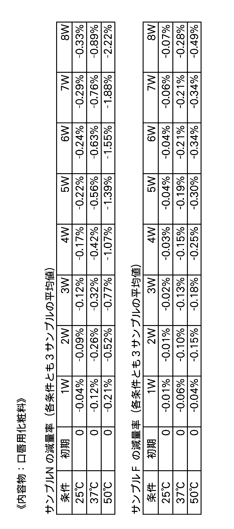
次に、本発明の繰出し容器に用いられるOリングの好ましい材料について説明する。本発明者等は、上記実施形態でも用いられたニトリルゴム(NBR)からなるOリングと、フッ素ゴム(詳しくは3M Companyのポリオール加硫2元)からなるOリングの内容物減量抑制効果、換言すれば内容物遮断効果を実験によって比較した。この実験に使用した繰出し容器は、形状は基本的に図2に示した上記実施形態の繰出し容器1と同じであるが、下の表2に示す通り、中具15がアルミニウムではなくPOM(ポリアセタール)から構成されている点で異なる。また、蓋体外筒21および蓋体内筒22は前述のサンプル6~9と同様に、それぞれアルミニウムおよびハイトレルから構成されている。そして比較のために、第1のOリング31および第2のOリング32の双方がニトリルゴムからなる繰出し容器(以下、これをサンプルNという)と、第1のOリング31がフッ素ゴムからなり第2のOリング32がニトリルゴムからなる繰出し容器(以下、これをサンプルFという)とを作成した。

比較のための実験では、サンプルNに内容物Mを充填したものを9個、そしてサンプルFに内容物Mを充填したものを同じく9個用意し、各サンプル毎に3個ずつ25°C、37°C、50°Cの環境下で閉蓋状態を保って静置した際の、内容物Mの減量率を測定した。ここで内容物Mは、前述した実施形態におけるのと同じもの、すなわち、イソドデカンおよび水を含む口唇用化粧料である。また減量率の測定および表示の仕方も前述した通りのものであり、本実験では初期状態からの経過時間が8週(W)に至るまで、各週毎に減量率を測定した。
この測定の結果を表3において、サンプルNについては上段に、サンプルFについては下段に示す。なお表3において各条件(環境温度)に関する測定結果は、上述した通りの3個のサンプルに関する測定結果の平均値を示している。ここに示される通り、サンプルFはサンプルNと比べて、3つの条件のいずれにおいても減量率が低い、つまり内容物遮断効果が高いことが分かる。
1 繰出し容器
10 本体部
11 本体外筒
11a 本体外筒の開放端
12 螺旋筒体
13 回転筒体
14 中皿
15 中具
15a 中具の第1の部分
15b 中具の第2の部分
15c 中具の凸部
16 保持部材
20 蓋体部
21 蓋体外筒
21a 蓋体外筒の開放端
22 蓋体内筒
31 第1のOリング
32 第2のOリング
10 本体部
11 本体外筒
11a 本体外筒の開放端
12 螺旋筒体
13 回転筒体
14 中皿
15 中具
15a 中具の第1の部分
15b 中具の第2の部分
15c 中具の凸部
16 保持部材
20 蓋体部
21 蓋体外筒
21a 蓋体外筒の開放端
22 蓋体内筒
31 第1のOリング
32 第2のOリング
Claims (6)
- 概略有底の円筒状に形成された金属製の本体外筒と、
前記本体外筒の内側に配された第1の部分と該本体外筒の開放端から延出した第2の部分とを有し、前記第1の部分が少なくとも一部において本体外筒と全周に亘って密接し、前記第2の部分が前記本体外筒の開放端に隣接した環状の凸部を構成している円筒状の金属製の中具と、
固形の内容物を保持し、前記本体外筒の内側に筒軸方向に移動自在に配された中皿と、
概略有底の円筒状に形成されて、開放側の端面が前記凸部に当接することにより、前記本体外筒と共に内部に閉空間を画成する金属製の蓋体外筒と、
前記蓋体外筒の内側に配されて、少なくとも一部が該蓋体外筒と全周に亘って密接している蓋体内筒と、
前記中皿を筒軸方向に移動させて前記内容物を前記中具から繰り出させる繰出し機構と、
を有する繰出し容器において、
前記中具の前記凸部よりも先端側の部分の周囲に嵌着されて、前記蓋体外筒が前記閉空間を画成する閉蓋位置に配されたとき該蓋体外筒と前記中具との間を気密に保つ第1のOリングと、前記中具の前記凸部よりも後端側の部分の周囲に嵌着されて、該中具と前記本体外筒との間を気密に保つ第2のOリングの少なくとも一方が設けられ、
前記蓋体内筒がポリエステル系エラストマーから構成されている、
繰出し容器。 - 前記第1のOリングと前記第2のOリングの双方が設けられている、請求項1に記載の繰出し容器。
- 前記中具に嵌着されたOリングがフッ素ゴムからなるものである、請求項1または2に記載の繰出し容器。
- 前記内容物が、水および炭化水素を含む固形組成物である、請求項1から3いずれか1項に記載の繰出し容器。
- 前記固形組成物が化粧料である、請求項4に記載の繰出し容器。
- 前記化粧料が口唇用化粧料である、請求項5に記載の繰出し容器。
Priority Applications (4)
| Application Number | Priority Date | Filing Date | Title |
|---|---|---|---|
| CN202080025120.0A CN113631061B (zh) | 2019-03-29 | 2020-03-23 | 送出容器 |
| EP20785086.8A EP3949800B1 (en) | 2019-03-29 | 2020-03-23 | Twist-up container |
| US17/599,408 US11896110B2 (en) | 2019-03-29 | 2020-03-23 | Feed out container |
| JP2021511474A JP7567123B2 (ja) | 2019-03-29 | 2020-03-23 | 繰出し容器 |
Applications Claiming Priority (2)
| Application Number | Priority Date | Filing Date | Title |
|---|---|---|---|
| JP2019-065405 | 2019-03-29 | ||
| JP2019065405 | 2019-03-29 |
Publications (1)
| Publication Number | Publication Date |
|---|---|
| WO2020203408A1 true WO2020203408A1 (ja) | 2020-10-08 |
Family
ID=72667704
Family Applications (1)
| Application Number | Title | Priority Date | Filing Date |
|---|---|---|---|
| PCT/JP2020/012695 Ceased WO2020203408A1 (ja) | 2019-03-29 | 2020-03-23 | 繰出し容器 |
Country Status (5)
| Country | Link |
|---|---|
| US (1) | US11896110B2 (ja) |
| EP (1) | EP3949800B1 (ja) |
| JP (1) | JP7567123B2 (ja) |
| CN (1) | CN113631061B (ja) |
| WO (1) | WO2020203408A1 (ja) |
Families Citing this family (2)
| Publication number | Priority date | Publication date | Assignee | Title |
|---|---|---|---|---|
| USD1010229S1 (en) * | 2021-08-02 | 2024-01-02 | Shiseido Company, Limited | Lipstick case |
| US12329265B2 (en) | 2022-08-19 | 2025-06-17 | Elc Management Llc | Cosmetic product container and retention mechanism |
Citations (8)
| Publication number | Priority date | Publication date | Assignee | Title |
|---|---|---|---|---|
| JPS6147897B2 (ja) | 1977-07-21 | 1986-10-21 | Tanaka Precious Metal Ind | |
| JPH09121938A (ja) * | 1995-10-31 | 1997-05-13 | Hidan:Kk | 化粧料容器 |
| US5888004A (en) * | 1996-06-26 | 1999-03-30 | L'oreal | Cup with a grooved interior side wall for holding a cosmetic stick |
| JP2002370934A (ja) * | 2001-06-13 | 2002-12-24 | Shiseido Co Ltd | 容器入り化粧料 |
| JP2005343567A (ja) * | 2000-03-16 | 2005-12-15 | L'oreal Sa | 化粧品又はケア製品を包装し及び適用するための装置 |
| JP2009136474A (ja) | 2007-12-06 | 2009-06-25 | Shiseido Co Ltd | 棒状化粧料容器 |
| JP2017518983A (ja) * | 2014-05-23 | 2017-07-13 | エルブイエムエイチ レシェルシェ | 多組成物化粧製品及び多組成物化粧製品を製造するための方法 |
| JP2017196279A (ja) * | 2016-04-28 | 2017-11-02 | 鈴野化成株式会社 | 化粧料カートリッジおよびカートリッジ式化粧料容器 |
Family Cites Families (10)
| Publication number | Priority date | Publication date | Assignee | Title |
|---|---|---|---|---|
| JPH0627912Y2 (ja) * | 1989-11-16 | 1994-07-27 | 横浜エイロクイップ株式会社 | 屈折管継手 |
| US5197814A (en) * | 1991-06-24 | 1993-03-30 | Elizabeth Arden Co., Division Of Conopco, Inc. | Lipstick article |
| KR100238850B1 (ko) * | 1994-07-08 | 2000-01-15 | 마츠누마 히데오 | 화장품 용기 |
| US5860755A (en) * | 1997-03-24 | 1999-01-19 | Bunk; Carole | Lipstick holder with mirror |
| JP3921366B2 (ja) * | 2001-09-18 | 2007-05-30 | 株式会社ヒダン | 棒状物品の繰り出し容器 |
| US7086796B2 (en) * | 2003-08-01 | 2006-08-08 | Bonne Bell, Inc. | Dispensing device |
| JP3796258B2 (ja) * | 2004-11-10 | 2006-07-12 | 株式会社トキワ | 液状充填物押出容器 |
| KR101149384B1 (ko) * | 2007-03-15 | 2012-06-01 | 가부시키가이샤 요시노 고교쇼 | 조출 용기 |
| JP6147897B1 (ja) * | 2016-06-29 | 2017-06-14 | 株式会社 資生堂 | 水中油型乳化唇用化粧料 |
| CN107826448B (zh) * | 2017-11-29 | 2024-05-14 | 珠海先河生物技术有限公司 | 罐盖和真空罐 |
-
2020
- 2020-03-23 JP JP2021511474A patent/JP7567123B2/ja active Active
- 2020-03-23 WO PCT/JP2020/012695 patent/WO2020203408A1/ja not_active Ceased
- 2020-03-23 CN CN202080025120.0A patent/CN113631061B/zh active Active
- 2020-03-23 EP EP20785086.8A patent/EP3949800B1/en active Active
- 2020-03-23 US US17/599,408 patent/US11896110B2/en active Active
Patent Citations (8)
| Publication number | Priority date | Publication date | Assignee | Title |
|---|---|---|---|---|
| JPS6147897B2 (ja) | 1977-07-21 | 1986-10-21 | Tanaka Precious Metal Ind | |
| JPH09121938A (ja) * | 1995-10-31 | 1997-05-13 | Hidan:Kk | 化粧料容器 |
| US5888004A (en) * | 1996-06-26 | 1999-03-30 | L'oreal | Cup with a grooved interior side wall for holding a cosmetic stick |
| JP2005343567A (ja) * | 2000-03-16 | 2005-12-15 | L'oreal Sa | 化粧品又はケア製品を包装し及び適用するための装置 |
| JP2002370934A (ja) * | 2001-06-13 | 2002-12-24 | Shiseido Co Ltd | 容器入り化粧料 |
| JP2009136474A (ja) | 2007-12-06 | 2009-06-25 | Shiseido Co Ltd | 棒状化粧料容器 |
| JP2017518983A (ja) * | 2014-05-23 | 2017-07-13 | エルブイエムエイチ レシェルシェ | 多組成物化粧製品及び多組成物化粧製品を製造するための方法 |
| JP2017196279A (ja) * | 2016-04-28 | 2017-11-02 | 鈴野化成株式会社 | 化粧料カートリッジおよびカートリッジ式化粧料容器 |
Non-Patent Citations (1)
| Title |
|---|
| See also references of EP3949800A4 |
Also Published As
| Publication number | Publication date |
|---|---|
| US11896110B2 (en) | 2024-02-13 |
| CN113631061B (zh) | 2024-11-05 |
| EP3949800A4 (en) | 2022-12-28 |
| EP3949800A1 (en) | 2022-02-09 |
| JPWO2020203408A1 (ja) | 2020-10-08 |
| EP3949800B1 (en) | 2025-03-05 |
| CN113631061A (zh) | 2021-11-09 |
| US20220183445A1 (en) | 2022-06-16 |
| JP7567123B2 (ja) | 2024-10-16 |
Similar Documents
| Publication | Publication Date | Title |
|---|---|---|
| EP2103542B1 (fr) | Dispositif de protection pour système de conditionnement d'un produit, notamment d'un produit cosmétique | |
| WO2020203408A1 (ja) | 繰出し容器 | |
| EP2298117B1 (fr) | Dispositif de conditionnement et de distribution d'un stick de produit, notamment d'un produit cosmétique | |
| JP2010082155A (ja) | 粘性化粧料用容器 | |
| US20180310613A1 (en) | Portable storage container | |
| KR200494153Y1 (ko) | 화장품 용기 | |
| EP3434143A1 (en) | Dispenser for storing and advancing a product | |
| US10874193B2 (en) | Wheel actuated cosmetic stick | |
| JP6600489B2 (ja) | 回転繰出容器 | |
| CA2551736A1 (en) | Bar-like cosmetic delivering container | |
| EP0182655A2 (en) | Holder for cosmetics stick | |
| JP2016220917A (ja) | 回転繰出容器 | |
| EP2881334B1 (fr) | Système de distribution d'un produit fluide contenu dans un récipient | |
| US9095200B2 (en) | Applicator device with a stripping means which is adjustable by way of a crumple zone | |
| DE502004002331D1 (de) | Spenderstift | |
| US11690430B2 (en) | Writing instrument container assemblies | |
| JP3113855U (ja) | 粘性化粧料用容器 | |
| JP7210116B2 (ja) | 繰出し容器 | |
| JP6953451B2 (ja) | 流体製品を供給するためのデバイス | |
| EP2074903A1 (fr) | Etui d'application d'au moins un produit par l'intermédiaire de deux applicateurs concentriques | |
| JP7507109B2 (ja) | 塗布容器 | |
| JP2001252131A (ja) | 鉛筆型物品用気密キャップ | |
| KR20200045374A (ko) | 화장품 용기 | |
| US993512A (en) | Receptacle for containing and discharging semisolid and pasty substances. | |
| JP2021160790A (ja) | 繰出し容器 |
Legal Events
| Date | Code | Title | Description |
|---|---|---|---|
| 121 | Ep: the epo has been informed by wipo that ep was designated in this application |
Ref document number: 20785086 Country of ref document: EP Kind code of ref document: A1 |
|
| ENP | Entry into the national phase |
Ref document number: 2021511474 Country of ref document: JP Kind code of ref document: A |
|
| NENP | Non-entry into the national phase |
Ref country code: DE |
|
| ENP | Entry into the national phase |
Ref document number: 2020785086 Country of ref document: EP Effective date: 20211029 |