WO2020203435A1 - 浮体構造物、浮体式風力発電装置及び浮体構造物の製造方法 - Google Patents
浮体構造物、浮体式風力発電装置及び浮体構造物の製造方法 Download PDFInfo
- Publication number
- WO2020203435A1 WO2020203435A1 PCT/JP2020/012849 JP2020012849W WO2020203435A1 WO 2020203435 A1 WO2020203435 A1 WO 2020203435A1 JP 2020012849 W JP2020012849 W JP 2020012849W WO 2020203435 A1 WO2020203435 A1 WO 2020203435A1
- Authority
- WO
- WIPO (PCT)
- Prior art keywords
- wind turbine
- floating structure
- floating
- wind
- output
- Prior art date
- Legal status (The legal status is an assumption and is not a legal conclusion. Google has not performed a legal analysis and makes no representation as to the accuracy of the status listed.)
- Ceased
Links
Images



Classifications
-
- F—MECHANICAL ENGINEERING; LIGHTING; HEATING; WEAPONS; BLASTING
- F03—MACHINES OR ENGINES FOR LIQUIDS; WIND, SPRING, OR WEIGHT MOTORS; PRODUCING MECHANICAL POWER OR A REACTIVE PROPULSIVE THRUST, NOT OTHERWISE PROVIDED FOR
- F03D—WIND MOTORS
- F03D13/00—Assembly, mounting or commissioning of wind motors; Arrangements specially adapted for transporting wind motor components
- F03D13/20—Arrangements for mounting or supporting wind motors; Masts or towers for wind motors
- F03D13/25—Arrangements for mounting or supporting wind motors; Masts or towers for wind motors specially adapted for offshore installation
-
- B—PERFORMING OPERATIONS; TRANSPORTING
- B63—SHIPS OR OTHER WATERBORNE VESSELS; RELATED EQUIPMENT
- B63B—SHIPS OR OTHER WATERBORNE VESSELS; EQUIPMENT FOR SHIPPING
- B63B35/00—Vessels or similar floating structures specially adapted for specific purposes and not otherwise provided for
- B63B35/44—Floating buildings, stores, drilling platforms, or workshops, e.g. carrying water-oil separating devices
-
- B—PERFORMING OPERATIONS; TRANSPORTING
- B63—SHIPS OR OTHER WATERBORNE VESSELS; RELATED EQUIPMENT
- B63B—SHIPS OR OTHER WATERBORNE VESSELS; EQUIPMENT FOR SHIPPING
- B63B75/00—Building or assembling floating offshore structures, e.g. semi-submersible platforms, SPAR platforms or wind turbine platforms
-
- B—PERFORMING OPERATIONS; TRANSPORTING
- B63—SHIPS OR OTHER WATERBORNE VESSELS; RELATED EQUIPMENT
- B63B—SHIPS OR OTHER WATERBORNE VESSELS; EQUIPMENT FOR SHIPPING
- B63B83/00—Rebuilding or retrofitting vessels, e.g. retrofitting ballast water treatment systems
-
- F—MECHANICAL ENGINEERING; LIGHTING; HEATING; WEAPONS; BLASTING
- F03—MACHINES OR ENGINES FOR LIQUIDS; WIND, SPRING, OR WEIGHT MOTORS; PRODUCING MECHANICAL POWER OR A REACTIVE PROPULSIVE THRUST, NOT OTHERWISE PROVIDED FOR
- F03D—WIND MOTORS
- F03D13/00—Assembly, mounting or commissioning of wind motors; Arrangements specially adapted for transporting wind motor components
- F03D13/20—Arrangements for mounting or supporting wind motors; Masts or towers for wind motors
- F03D13/25—Arrangements for mounting or supporting wind motors; Masts or towers for wind motors specially adapted for offshore installation
- F03D13/256—Arrangements for mounting or supporting wind motors; Masts or towers for wind motors specially adapted for offshore installation on a floating support, i.e. floating wind motors
-
- B—PERFORMING OPERATIONS; TRANSPORTING
- B63—SHIPS OR OTHER WATERBORNE VESSELS; RELATED EQUIPMENT
- B63B—SHIPS OR OTHER WATERBORNE VESSELS; EQUIPMENT FOR SHIPPING
- B63B35/00—Vessels or similar floating structures specially adapted for specific purposes and not otherwise provided for
- B63B35/44—Floating buildings, stores, drilling platforms, or workshops, e.g. carrying water-oil separating devices
- B63B2035/4433—Floating structures carrying electric power plants
- B63B2035/446—Floating structures carrying electric power plants for converting wind energy into electric energy
-
- F—MECHANICAL ENGINEERING; LIGHTING; HEATING; WEAPONS; BLASTING
- F05—INDEXING SCHEMES RELATING TO ENGINES OR PUMPS IN VARIOUS SUBCLASSES OF CLASSES F01-F04
- F05B—INDEXING SCHEME RELATING TO WIND, SPRING, WEIGHT, INERTIA OR LIKE MOTORS, TO MACHINES OR ENGINES FOR LIQUIDS COVERED BY SUBCLASSES F03B, F03D AND F03G
- F05B2230/00—Manufacture
- F05B2230/80—Repairing, retrofitting or upgrading methods
-
- F—MECHANICAL ENGINEERING; LIGHTING; HEATING; WEAPONS; BLASTING
- F05—INDEXING SCHEMES RELATING TO ENGINES OR PUMPS IN VARIOUS SUBCLASSES OF CLASSES F01-F04
- F05B—INDEXING SCHEME RELATING TO WIND, SPRING, WEIGHT, INERTIA OR LIKE MOTORS, TO MACHINES OR ENGINES FOR LIQUIDS COVERED BY SUBCLASSES F03B, F03D AND F03G
- F05B2240/00—Components
- F05B2240/90—Mounting on supporting structures or systems
- F05B2240/93—Mounting on supporting structures or systems on a structure floating on a liquid surface
-
- F—MECHANICAL ENGINEERING; LIGHTING; HEATING; WEAPONS; BLASTING
- F05—INDEXING SCHEMES RELATING TO ENGINES OR PUMPS IN VARIOUS SUBCLASSES OF CLASSES F01-F04
- F05B—INDEXING SCHEME RELATING TO WIND, SPRING, WEIGHT, INERTIA OR LIKE MOTORS, TO MACHINES OR ENGINES FOR LIQUIDS COVERED BY SUBCLASSES F03B, F03D AND F03G
- F05B2240/00—Components
- F05B2240/90—Mounting on supporting structures or systems
- F05B2240/93—Mounting on supporting structures or systems on a structure floating on a liquid surface
- F05B2240/932—Mounting on supporting structures or systems on a structure floating on a liquid surface which is a catamaran-like structure
-
- F—MECHANICAL ENGINEERING; LIGHTING; HEATING; WEAPONS; BLASTING
- F05—INDEXING SCHEMES RELATING TO ENGINES OR PUMPS IN VARIOUS SUBCLASSES OF CLASSES F01-F04
- F05B—INDEXING SCHEME RELATING TO WIND, SPRING, WEIGHT, INERTIA OR LIKE MOTORS, TO MACHINES OR ENGINES FOR LIQUIDS COVERED BY SUBCLASSES F03B, F03D AND F03G
- F05B2240/00—Components
- F05B2240/90—Mounting on supporting structures or systems
- F05B2240/95—Mounting on supporting structures or systems offshore
-
- F—MECHANICAL ENGINEERING; LIGHTING; HEATING; WEAPONS; BLASTING
- F05—INDEXING SCHEMES RELATING TO ENGINES OR PUMPS IN VARIOUS SUBCLASSES OF CLASSES F01-F04
- F05B—INDEXING SCHEME RELATING TO WIND, SPRING, WEIGHT, INERTIA OR LIKE MOTORS, TO MACHINES OR ENGINES FOR LIQUIDS COVERED BY SUBCLASSES F03B, F03D AND F03G
- F05B2240/00—Components
- F05B2240/90—Mounting on supporting structures or systems
- F05B2240/97—Mounting on supporting structures or systems on a submerged structure
-
- Y—GENERAL TAGGING OF NEW TECHNOLOGICAL DEVELOPMENTS; GENERAL TAGGING OF CROSS-SECTIONAL TECHNOLOGIES SPANNING OVER SEVERAL SECTIONS OF THE IPC; TECHNICAL SUBJECTS COVERED BY FORMER USPC CROSS-REFERENCE ART COLLECTIONS [XRACs] AND DIGESTS
- Y02—TECHNOLOGIES OR APPLICATIONS FOR MITIGATION OR ADAPTATION AGAINST CLIMATE CHANGE
- Y02E—REDUCTION OF GREENHOUSE GAS [GHG] EMISSIONS, RELATED TO ENERGY GENERATION, TRANSMISSION OR DISTRIBUTION
- Y02E10/00—Energy generation through renewable energy sources
- Y02E10/70—Wind energy
- Y02E10/72—Wind turbines with rotation axis in wind direction
-
- Y—GENERAL TAGGING OF NEW TECHNOLOGICAL DEVELOPMENTS; GENERAL TAGGING OF CROSS-SECTIONAL TECHNOLOGIES SPANNING OVER SEVERAL SECTIONS OF THE IPC; TECHNICAL SUBJECTS COVERED BY FORMER USPC CROSS-REFERENCE ART COLLECTIONS [XRACs] AND DIGESTS
- Y02—TECHNOLOGIES OR APPLICATIONS FOR MITIGATION OR ADAPTATION AGAINST CLIMATE CHANGE
- Y02E—REDUCTION OF GREENHOUSE GAS [GHG] EMISSIONS, RELATED TO ENERGY GENERATION, TRANSMISSION OR DISTRIBUTION
- Y02E10/00—Energy generation through renewable energy sources
- Y02E10/70—Wind energy
- Y02E10/727—Offshore wind turbines
-
- Y—GENERAL TAGGING OF NEW TECHNOLOGICAL DEVELOPMENTS; GENERAL TAGGING OF CROSS-SECTIONAL TECHNOLOGIES SPANNING OVER SEVERAL SECTIONS OF THE IPC; TECHNICAL SUBJECTS COVERED BY FORMER USPC CROSS-REFERENCE ART COLLECTIONS [XRACs] AND DIGESTS
- Y02—TECHNOLOGIES OR APPLICATIONS FOR MITIGATION OR ADAPTATION AGAINST CLIMATE CHANGE
- Y02P—CLIMATE CHANGE MITIGATION TECHNOLOGIES IN THE PRODUCTION OR PROCESSING OF GOODS
- Y02P70/00—Climate change mitigation technologies in the production process for final industrial or consumer products
- Y02P70/50—Manufacturing or production processes characterised by the final manufactured product
Definitions
- the present invention relates to a method for manufacturing a floating structure, a floating wind power generator, and a floating structure, and in particular, a method for manufacturing a floating structure, a floating wind power generator, and a floating structure that can be adapted to future enlargement of a wind turbine. Regarding.
- the detailed design of the wind turbine is made, and the total weight of the superstructure (wind turbine and its ancillary equipment) placed on the floating structure is determined. It is common to design a floating structure based on the calculated weight.
- Patent Document 1 aims to provide a method for designing a floating wind turbine that can accurately estimate the influence of repeated loads due to wind and waves and reflect it in a fatigue strength design.
- the floating body 1 is designed to generate a buoyancy larger than the total weight of the floating wind power generator 10a, and the entire floating wind turbine 10a is set on the water surface W. It can float.
- the floating structure used in the floating wind power generator is designed based on the total weight of the superstructure, and from the viewpoint of cost reduction, it generates the minimum necessary buoyancy including the safety factor. Designed to be.
- the present invention has been devised in view of the above problems, and is a floating structure, a floating wind power generator, and a floating structure that can be installed by exchanging the wind turbine even when the wind turbine becomes large. It is an object of the present invention to provide a manufacturing method.
- a floating structure characterized by having a buoyancy capable of installing a second wind turbine having an output larger than that of the first wind turbine to be mounted.
- a floating wind power generation device including a floating structure having a buoyancy capable of installing a second wind turbine having an output larger than the output of the first wind turbine to be mounted. Will be done.
- the floating structure may have a pedestal that replaceably supports the first wind turbine and the second wind turbine. Further, the floating structure may have an attachment arranged between the first wind turbine or the second wind turbine and the pedestal. Further, the floating structure may have a useful life at least longer than the useful life of the first wind turbine.
- a method for manufacturing a floating structure is provided, which comprises.
- the floating structure, the floating wind power generator, and the method for manufacturing the floating structure according to the present invention described above it is possible to install a second wind turbine in which the floating structure has an output larger than the output of the first wind turbine to be mounted. Due to its large buoyancy, even if the wind turbine becomes larger in the future, it will be made larger by using the floating structure that has been used until then, without manufacturing a new floating structure. The wind turbine can be replaced and installed.
- the number of years of using the floating structure can be extended, and by making the useful life of the floating structure correspond to the number of years of use in advance, the cost (depreciation cost) required for each year during operation. Can be substantially reduced, and power generation profit can be easily improved.
- FIG. 1 It is an overall block diagram which shows the floating wind power generation apparatus which concerns on one Embodiment of this invention. It is an enlarged view which shows the connection part of a floating structure and a first wind turbine, (A) is a component development view, (B) is a cross-sectional top view. It is a flow chart which shows the manufacturing method of the floating structure which concerns on one Embodiment of this invention. It is a cross-sectional top view which shows the connection part of a floating structure and a 2nd wind turbine, (A) shows 1st example, (B) shows 2nd example. It is a figure which shows the modification of the connection part of a floating body structure and a wind turbine, (A) shows the connection part of the 1st wind turbine, and (B) shows the connection part of the 2nd wind turbine.
- FIG. 1 is an overall configuration diagram showing a floating wind power generator according to an embodiment of the present invention.
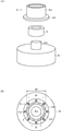
- 2A and 2B are enlarged views showing a connecting portion between the floating structure and the first wind turbine, where FIG. 2A is a component development view and FIG. 2B is a cross-sectional top view.
- FIG. 3 is a flow chart showing a method for manufacturing a floating structure according to an embodiment of the present invention.
- the floating wind turbine 1 is based on the outputs of the first wind turbine 2 that generates electricity by receiving wind and rotationally driving it, and the first wind turbine 2 to be mounted. Also has a floating structure 4 having a large output and a buoyancy capable of installing a second wind turbine 3 that may be mounted in the future.
- the first wind turbine 2 which is the superstructure of the floating structure 4, has, for example, a tower 21, a nacelle 22, and a blade 23.
- the tower 21 is a support column that supports the nacelle 22 and the blade 23, and is connected to the pedestal 47 of the floating structure 4.
- the nacelle 22 has a generator inside, and generates electric power by the rotation of the blade 23.
- the blade 23 is rotatably supported by the nacelle 22 and is configured to be rotationally driven by wind power.
- the floating structure 4 is, for example, a semi-sub (semi-submersible) type floating body.
- the floating structure 4 is not limited to the semi-sub type floating body, and may be another type of floating body such as a barge type, a spar type, or a tension mooring platform type.
- the semi-sub type floating structure 4 includes, for example, a center column 41 arranged at the center of the floating structure 4, a plurality of (for example, three) side columns 42 arranged on the outer periphery of the center column 41, and a center column.
- the structure of the semi-sub type floating body is merely an example, and is not limited to the illustrated structure.
- the center column 41 and the side column 42 form a so-called ballast tank, and seawater can be injected and drained into the internal cavity as needed.
- a pedestal 47 on which the first wind turbine 2 is installed is arranged in the center of the platform 43.
- the lower brace 44 and the diagonal brace 45 are members that maintain the strength of the floating structure 4.
- the pedestal 47 is, for example, a cylindrical or disk-shaped convex portion formed on the platform 43, as shown in FIG. 2 (A). At the center of the pedestal 47, a support shaft 47a that can be inserted into the tower 21 is erected. Further, although not shown, a plurality of bolt holes may be formed on the upper surface of the pedestal 47 substantially radially around the support shaft 47a. The bolt holes may be formed in the flange portion formed on the outer periphery of the upper surface of the pedestal 47. Although not shown, the pedestal 47 may have a shape other than a cylindrical shape or a disk shape (for example, a prismatic shape).
- the tower 21 includes a cylindrical annular portion 21a formed at the lower end portion over a certain range (height) and a flange portion 21b formed at the edge portion of the lower end portion.
- the flange portion 21b is formed with a plurality of openings into which bolts 21c (see FIG. 2B) can be screwed into bolt holes formed in the pedestal 47.
- the outer shape and opening of the flange portion 21b are formed so as to match the positions of the bolt holes arranged on the pedestal 47.
- the diameter of the support shaft 47a is defined as D1
- the inner diameter of the annular portion 21a is defined as D2
- the outer diameter of the annular portion 21a is defined as D3, the relationship D1 ⁇ D2 ⁇ D3.
- the diameter D1 of the support shaft 47a is sufficiently smaller than the inner diameter D2 of the annular portion 21a while maintaining a certain strength so that the support shaft 47a can be inserted without contacting the annular portion 21a. It is set to.
- the floating wind power generation device 1 includes an attachment 5 that is fitted on the outer circumference of the support shaft 47a and is fitted on the inner circumference of the annular portion 21a.
- the attachment 5 has an inner diameter of D1 (correctly, a diameter slightly larger than D1) and an outer diameter of D2 (more accurately, a diameter slightly smaller than D2). ) Is a cylindrical part. Since the attachment 5 is arranged between the annular portion 21a of the tower 21 and the support shaft 47a of the pedestal 47, it can be said that the attachment 5 is arranged between the first wind turbine 2 and the pedestal 47.
- the buoyancy of the floating structure 4 described above has been conventionally designed based on the total weight of the first wind turbine 2 to be mounted. Therefore, since the useful life of the floating structure 4 is generally longer than the useful life of the first wind turbine 2, the useful life of the first wind turbine 2 determines the life (useful life) of the floating wind power generator 1. Clearly, even if only the first wind turbine 2 is replaced with a new wind turbine, the buoyancy of the floating structure 4 is determined based on the total weight of the first wind turbine 2, so that the wind turbine larger than the first wind turbine 2 has a floating structure. It cannot be mounted on the object 4.
- the floating wind turbine 1 has a larger output than the first wind turbine 2 to be mounted so that it is not necessary to manufacture a new floating structure even when the wind turbine is enlarged.
- the required buoyancy is calculated based on the total weight of the second wind turbine 3 to be held, and the floating structure 4 is designed and manufactured.
- the method for manufacturing the floating structure 4 according to the present embodiment is larger than the output of the first step Step 1 for determining the output of the first wind turbine 2 to be mounted and the output of the first wind turbine 2.
- the output (power generation capacity) of the first wind turbine 2 to be mounted is 7.5 MW class
- the output (power generation capacity) of 10 MW class is required in a few years, and the output of 15 MW class or more in 5 to 10 years. (Power generation capacity) is expected to be required.
- the floating structure 4 has a useful life of 30 to 40 years, it is assumed that the second wind turbine 3 has an output (power generation capacity) of 15 MW class or more, and the total weight thereof is calculated.
- the buoyancy required to mount the wind turbine 3 will be calculated.
- the initial cost for mounting the first wind turbine 2 is high, but when the first wind turbine 2 is replaced with a larger second wind turbine 3. Costs such as removal work costs and manufacturing costs required for the above can be significantly reduced.
- the useful life of the floating structure 4 is the sum of the useful lives of the first wind turbine 2 and the second wind turbine 3 (20). It may have a longer useful life than (years). Further, since it is difficult to accurately predict the useful life of the second wind turbine 3 to be mounted in the future at the time of mounting the first wind turbine 2, the useful life of the floating structure 4 is the first wind turbine. The useful life may be, for example, about 5 to 10 years longer than the useful life of 2. That is, the floating structure 4 is designed and manufactured according to specifications having a useful life at least longer than the useful life of the first wind turbine 2.
- FIG. 4 is a cross-sectional top view showing a connecting portion between the floating structure and the second wind turbine, where (A) shows the first example and (B) shows the second example.
- the second wind turbine 3 has an annular portion 31a and a flange portion 31b at the lower end of the tower 31. If the inner diameter of the annular portion 31a is defined as D2'and the outer diameter of the annular portion 31a is defined as D3', there is a relationship of D1 ⁇ D2' ⁇ D3'.
- the attachment 5' has an inner diameter of D1'(a diameter slightly larger than D1') and an outer diameter of D2'(a diameter slightly smaller than D2'). It is a cylindrical part having. Since the attachment 5'is arranged between the annular portion 31a of the tower 31 and the support shaft 47a of the pedestal 47, it can be said that the attachment 5'is arranged between the second wind turbine 3 and the pedestal 47. ..
- the attachment 5 is removed, and a new attachment 5'is installed on the pedestal 47.
- the second wind turbine 3 may be installed.
- the tower 31 is connected to the pedestal 47 by the bolt 31c. Further, the replacement of the wind turbine is not limited to one time, and the wind turbine may be continuously replaced two or three times so that the floating structure 4 can be used for a long period of time.
- the tower 31 tends to become thicker as the wind turbine becomes larger, but the thickness of the tower 31 is thinner than the thickness of the tower 21 of the first wind turbine 2 depending on the technical ability when installing the second wind turbine 3. There is also the possibility of becoming.
- the attachment 5' can be formed into a thin cylindrical shape.
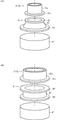
- FIG. 5 is a diagram showing a modified example of the connecting portion between the floating structure and the wind turbine, where (A) shows the connecting portion of the first wind turbine and (B) shows the connecting portion of the second wind turbine. There is.
- the support shaft 47a is not formed on the pedestal 47, the first wind turbine 2 is connected to the pedestal 47 via the attachment 6, and the attachment 6 The second wind turbine 3 is connected to the pedestal 47 via ′.
- the attachment 6 shown in FIG. 5A has a truncated cone-shaped outer shape, a first flange portion 62 arranged at the upper end of the trunk portion 61 and bolted to the flange portion 21b, and a body portion 61.
- a second flange portion 63 which is arranged at the lower end of the above and is bolted to the pedestal 47, is provided.
- the openings formed in the flange portion 21b, the bolt holes formed in the pedestal 47, and the bolts connecting the respective portions are omitted for convenience of explanation.
- the attachment 6'shown in FIG. 5B includes a body portion 61'having a cylindrical outer shape, a first flange portion 62'arranged at the upper end of the body portion 61'and bolted to the flange portion 21b. It includes a second flange portion 63'arranged at the lower end of the body portion 61 and bolted to the pedestal 47.
- the openings formed in the flange portion 31b, the bolt holes formed in the pedestal 47, and the bolts connecting the respective portions are not shown for convenience of explanation.
- the attachment 6 having a shape suitable for the lower end structure (annular portion 21a, flange portion 21b) of the tower 21 of the first wind turbine 2 and the lower end structure (annular portion 31a, flange portion) of the tower 31 of the second wind turbine 3
- the attachment 6' With a shape conforming to 31b), the first wind turbine 2 and the second wind turbine 3 can be installed on the pedestal 47 of the floating structure 4.
- the floating structure 4 has an output larger than the output of the first wind turbine 2 to be mounted. Since the second wind turbine 3 has a buoyancy that allows it to be installed, even if the wind turbine becomes larger in the future, the floating structure that has been used until then without newly manufacturing the floating structure 4 It is possible to replace and install the second wind turbine 3 which has been enlarged by using the object 4.
- the number of years of use of the floating structure 4 can be extended, and by making the useful life of the floating structure 4 correspond to the number of years of use in advance, each year required for operation
- the cost (depreciation cost) can be substantially reduced, and the power generation profit can be easily improved.
Landscapes
- Engineering & Computer Science (AREA)
- Chemical & Material Sciences (AREA)
- Mechanical Engineering (AREA)
- Combustion & Propulsion (AREA)
- Ocean & Marine Engineering (AREA)
- Architecture (AREA)
- Structural Engineering (AREA)
- Sustainable Energy (AREA)
- Sustainable Development (AREA)
- General Engineering & Computer Science (AREA)
- Life Sciences & Earth Sciences (AREA)
- Water Supply & Treatment (AREA)
- Civil Engineering (AREA)
- Wind Motors (AREA)
Abstract
風車が大型化した場合であっても風車を交換して設置することができる、浮体構造物、浮体式風力発電装置及び浮体構造物の製造方法を提供する。本実施形態に係る浮体式風力発電装置1は、風を受けて回転駆動することによって発電する第一風車2と、実装する第一風車2の出力よりも大きな出力を有し、将来的に実装する可能性のある第二風車3を設置可能な浮力を有する浮体構造物4と、を備えている。この浮体式風力発電装置1では、風車が大型化した場合であっても新たな浮体構造物を製造する必要がないように、実装する第一風車2よりも大きな出力を有する第二風車3の総重量に基づいて必要な浮力を算出し、浮体構造物4を設計・製造している。
Description
本発明は、浮体構造物、浮体式風力発電装置及び浮体構造物の製造方法に関し、特に、将来の風車の大型化に適応可能な浮体構造物、浮体式風力発電装置及び浮体構造物の製造方法に関する。
浮体式風力発電装置の分野では、風車の出力(発電容量)が決定した後、風車の詳細設計がなされ、浮体構造物上に配置される上部構造物(風車及びその附帯設備)の総重量が算出され、その総重量に基づいて浮体構造物の設計を行うことが一般的である。
例えば、特許文献1に記載された発明は、風と波浪とによる繰り返し荷重の影響を精度よく見積もって、疲労強度設計に反映させることできる浮体式風力発電装置の設計方法を提供することを目的とするものであるが、段落0020には、「浮体1は、浮体式風力発電装置10aの総重量よりも大きい浮力を発生するように設計されており、浮体式風力発電装置10a全体を水面Wに浮かべることができる。」ことが記載されている。
上述したように、浮体式風力発電装置に用いられる浮体構造物は、上部構造物の総重量を基準に設計されるところ、費用削減の観点から、安全率を含む必要最小限の浮力を発生するように設計される。
ところで、近年、風車の出力(発電容量)は大きくなる傾向にあり、風車の大型化に伴って浮体構造物を設計し直して大型の風車に耐え得る浮体構造物を製造する必要がある。したがって、風車の大型化に伴って浮体式風力発電設備の製造コストも増大するという問題点がある。また、特に浮体式風力発電装置の分野は、発電事業の収益性の観点から更なるコストダウンが必要とされている。
本発明はかかる問題点に鑑み創案されたものであり、風車が大型化した場合であっても風車を交換して設置することができる、浮体構造物、浮体式風力発電装置及び浮体構造物の製造方法を提供することを目的とする。
本発明によれば、実装する第一風車の出力よりも大きな出力を有する第二風車を設置可能な浮力を有する、ことを特徴とする浮体構造物が提供される。
また、本発明によれば、実装する第一風車の出力よりも大きな出力を有する第二風車を設置可能な浮力を有する浮体構造物を備えた、ことを特徴とする浮体式風力発電装置が提供される。
前記浮体構造物は、前記第一風車及び前記第二風車を交換可能に支持する台座を有していてもよい。また、前記浮体構造物は、前記第一風車又は前記第二風車と前記台座との間に配置されるアタッチメントを有していてもよい。また、前記浮体構造物は、少なくとも前記第一風車の耐用年数よりも長い耐用年数を有していてもよい。
また、本発明によれば、実装する第一風車の出力を決定する第一工程と、前記第一風車の出力よりも大きな出力を有し、かつ、将来的に実装する可能性のある第二風車の最大出力を決定する第二工程と、前記第二風車を設置可能な前記浮体構造物の浮力を算出する第三工程と、前記浮力に基づいて前記浮体構造物を設計する第四工程と、を含むことを特徴とする浮体構造物の製造方法が提供される。
上述した本発明に係る浮体構造物、浮体式風力発電装置及び浮体構造物の製造方法によれば、浮体構造物が、実装する第一風車の出力よりも大きな出力を有する第二風車を設置可能な浮力を有していることから、将来的に風車が大型化した場合であっても浮体構造物を新たに製造することなく、それまで使用していた浮体構造物を利用して大型化した風車を交換して設置することができる。
また、かかる発明により、浮体構造物を使用する年数を長くすることができ、浮体構造物の耐用年数を予めその使用年数に対応させておくことにより、稼働時に要する各年のコスト(償却費)を実質的に低減することができ、簡便に発電収益を改善することもできる。
以下、本発明の実施形態について図1~図5(B)を用いて説明する。ここで、図1は、本発明の一実施形態に係る浮体式風力発電装置を示す全体構成図である。図2は、浮体構造物と第一風車との連結部を示す拡大図であり、(A)は部品展開図、(B)は断面上面図、を示している。図3は、本発明の一実施形態に係る浮体構造物の製造方法を示すフロー図である。
本発明の一実施形態に係る浮体式風力発電装置1は、図1に示したように、風を受けて回転駆動することによって発電する第一風車2と、実装する第一風車2の出力よりも大きな出力を有し、将来的に実装する可能性のある第二風車3を設置可能な浮力を有する浮体構造物4と、を備えている。
浮体構造物4の上部構造物である第一風車2は、例えば、タワー21、ナセル22及びブレード23を有している。タワー21は、ナセル22及びブレード23を支持する支柱であり、浮体構造物4の台座47に連結される。ナセル22は、内部に発電機を有し、ブレード23の回転によって電力を発生させる。ブレード23は、ナセル22に回転可能に支持されており、風力によって回転駆動するように構成されている。
浮体構造物4は、例えば、セミサブ(セミサブマーシブル:半潜水)型の浮体である。なお、浮体構造物4は、セミサブ型の浮体に限定されるものではなく、バージ型、スパー型、緊張係留式プラットフォーム型等の他の型式の浮体であってもよい。
セミサブ型の浮体構造物4は、例えば、浮体構造物4の中心に配置されるセンターコラム41と、センターコラム41の外周に配置される複数(例えば、三本)のサイドコラム42と、センターコラム41及びサイドコラム42の上部に配置されるプラットフォーム43と、センターコラム41及びサイドコラム42を連結する下部ブレース44と、プラットフォーム43及びサイドコラム42を連結する斜めブレース45と、浮体構造物4を海底に係留する係留索46と、を備えている。なお、かかるセミサブ型浮体の構造は単なる一例であり、図示した構造に限定されるものではない。
センターコラム41及びサイドコラム42は、いわゆるバラストタンクを構成しており、内部の空洞に必要に応じて海水を注排水可能に構成されている。プラットフォーム43の中心部には第一風車2を設置する台座47が配置されている。下部ブレース44及び斜めブレース45は浮体構造物4の強度を保持する部材である。
台座47は、例えば、図2(A)に示したように、プラットフォーム43上に形成された円柱形状又は円板形状の凸部である。台座47の中心部には、タワー21に挿通可能な支持軸47aが立設されている。また、図示しないが、台座47の上面には支持軸47aを中心にして略放射状に複数のボルト穴が形成されていてもよい。ボルト穴は、台座47の上面の外周に形成されたフランジ部に形成されていてもよい。なお、図示しないが、台座47は円柱形状や円板形状以外の形状(例えば、角柱形状等)であってもよい。
タワー21は、下端部に一定の範囲(高さ)に渡って形成された円筒形状の環状部21aと、下端部の縁部に形成されたフランジ部21bと、を備えている。図示しないが、フランジ部21bには、台座47に形成されたボルト穴にボルト21c(図2(B)参照)を螺合可能な複数の開口部が形成されている。フランジ部21bの外形及び開口部は、台座47上に配置されたボルト穴の位置に適合するように形成される。
ここで、図2(B)に記載したように、支持軸47aの直径をD1、環状部21aの内径をD2、環状部21aの外径をD3と定義すれば、D1<D2<D3の関係を有している。また、支持軸47aは、環状部21aに接触せずに挿入することができるように、支持軸47aの直径D1は、一定の強度を保持しつつ、環状部21aの内径D2より十分に小さい大きさに設定されている。
したがって、台座47上にタワー21を配置した場合、支持軸47aと環状部21aとの間には隙間が生じることとなる。そこで、本実施形態に係る浮体式風力発電装置1では、支持軸47aの外周に嵌挿されるとともに環状部21aの内周に嵌挿されるアタッチメント5を備えている。
図2(A)及び図2(B)に示したように、アタッチメント5は、D1の内径(正確にはD1より僅かに大きい径)及びD2の外径(正確にはD2より僅かに小さい径)を有する円筒形状の部品である。かかるアタッチメント5は、タワー21の環状部21aと台座47の支持軸47aとの間に配置されていることから、第一風車2と台座47との間に配置されていると言い換えることもできる。
ところで、上述した浮体構造物4の浮力は、従来、実装される第一風車2の総重量に基づいて設計されていた。したがって、浮体構造物4の耐用年数は一般に第一風車2の耐用年数よりも長いことから、第一風車2の耐用年数によって浮体式風力発電装置1の寿命(耐用年数)が決まってしまうこととなる。また、第一風車2のみを新しい風車に交換するとしても、浮体構造物4の浮力は第一風車2の総重量に基づいて決まっていることから、第一風車2よりも大きな風車を浮体構造物4に搭載することはできない。
一方で、近年、浮体式風力発電装置に求められる出力(発電容量)は年々増加する傾向にある。したがって、浮体式風力発電装置を設置して5~10年後には、より大型の風車の設置を求められることとなる。風車が大型化すれば、その総重量も増加することとなる。結局、風車の大型化に対応するために、それに見合った浮体構造物を新たに製造しなければならない。
そこで、本実施形態に係る浮体式風力発電装置1では、風車が大型化した場合であっても新たな浮体構造物を製造する必要がないように、実装する第一風車2よりも大きな出力を有する第二風車3の総重量に基づいて必要な浮力を算出し、浮体構造物4を設計・製造している。
すなわち、本実施形態に係る浮体構造物4の製造方法は、図3に示したように、実装する第一風車2の出力を決定する第一工程Step1と、第一風車2の出力よりも大きな出力を有し、かつ、将来的に実装する可能性のある第二風車3の出力を決定する第二工程Step2と、第二風車3を設置可能な浮体構造物4の浮力を算出する第三工程Step3と、算出した浮力に基づいて浮体構造物4を設計する第四工程Step4と、を含んでいる。
例えば、実装する第一風車2の出力(発電容量)が7.5MW級である場合、数年後には10MW級の出力(発電容量)が求められ、5~10年後には15MW級以上の出力(発電容量)が求められるものと予測される。
浮体構造物4の耐用年数が30~40年であるとすれば、少なくとも第二風車3として15MW級以上の出力(発電容量)を有する風車を想定し、その総重量を算出し、かかる第二風車3を搭載するために必要な浮力を算出することとなる。かかる算出した浮力に基づいて浮体構造物4を設計・製造した場合、第一風車2を実装する際のイニシャルコストは高くなるものの、第一風車2を大型化した第二風車3に交換する際に必要な撤去工事費や製造費等のコストを大幅に削減することができる。
また、例えば、第一風車2及び第二風車3の耐用年数がそれぞれ10年であるとすれば、浮体構造物4の耐用年数は第一風車2及び第二風車3の耐用年数の総和(20年)よりも長い耐用年数を有していてもよい。また、将来的に実装される第二風車3の耐用年数は、第一風車2を実装する時点において正確に予測することは困難であることから、浮体構造物4の耐用年数は、第一風車2の耐用年数よりも、例えば、5~10年程度長い耐用年数であってもよい。すなわち、浮体構造物4は、少なくとも第一風車2の耐用年数よりも長い耐用年数を有する仕様によって設計・製造されている。
ここで、図4は、浮体構造物と第二風車との連結部を示す断面上面図であり、(A)は第一例、(B)は第二例、を示している。第二風車3は、タワー31の下端部に環状部31a及びフランジ部31bを有している。環状部31aの内径をD2′、環状部31aの外径をD3′と定義すれば、D1≪D2′<D3′の関係を有している。
図4(A)に示したように、アタッチメント5′は、D1′の内径(正確にはD1′より僅かに大きい径)及びD2′の外径(正確にはD2′より僅かに小さい径)を有する円筒形状の部品である。かかるアタッチメント5′は、タワー31の環状部31aと台座47の支持軸47aとの間に配置されていることから、第二風車3と台座47との間に配置されていると言い換えることもできる。
また、第一風車2から第二風車3に交換する際には、浮体構造物4から第一風車2を撤去した後、アタッチメント5を撤去し、新しいアタッチメント5′を台座47に設置した後、第二風車3を設置するようにすればよい。なお、タワー31はボルト31cによって台座47に連結される。また、風車の交換は一回に限られず、二回、三回と継続して風車を交換して、浮体構造物4を長期間に渡って使用するようにしてもよい。
一般に、風車の大型化に伴ってタワー31も太くなる傾向にあるが、第二風車3を設置する際の技術力によってはタワー31の太さが第一風車2のタワー21の太さよりも細くなる可能性もある。この場合には、例えば、図4(B)に示したように、アタッチメント5′を肉厚の薄い円筒形状に形成することにより対応することができる。
上述した実施形態では、アタッチメント5,5′を介して支持軸47aに環状部21a,31aを嵌挿する連結構造であったが、連結構造はかかる構成に限定されるものではない。ここで、図5は、浮体構造物と風車との連結部の変形例を示す図であり、(A)は第一風車の連結部、(B)は第二風車の連結部、を示している。
図5(A)及び図5(B)に示した変形例では、台座47には支持軸47aが形成されておらず、アタッチメント6を介して第一風車2が台座47に連結され、アタッチメント6′を介して第二風車3が台座47に連結される。
図5(A)に示したアタッチメント6は、円錐台形状の外形を有する胴部61と、胴部61の上端に配置されフランジ部21bにボルト締結される第一フランジ部62と、胴部61の下端に配置され台座47にボルト締結される第二フランジ部63と、を備えている。なお、フランジ部21bに形成された開口部、台座47に形成されたボルト穴及び各部を連結するボルトについては、説明の便宜上、図を省略してある。
図5(B)に示したアタッチメント6′は、円筒形状の外形を有する胴部61′と、胴部61′の上端に配置されフランジ部21bにボルト締結される第一フランジ部62′と、胴部61の下端に配置され台座47にボルト締結される第二フランジ部63′と、を備えている。なお、フランジ部31bに形成された開口部、台座47に形成されたボルト穴及び各部を連結するボルトにつては、説明の便宜上、図を省略してある。
このように、第一風車2のタワー21の下端部構造(環状部21a,フランジ部21b)に適合した形状のアタッチメント6及び第二風車3のタワー31の下端部構造(環状部31a,フランジ部31b)に適合した形状のアタッチメント6′を用いることにより、第一風車2及び第二風車3を浮体構造物4の台座47に設置することができる。
上述した本実施形態に係る浮体構造物4、浮体式風力発電装置1及び浮体構造物4の製造方法によれば、浮体構造物4が、実装する第一風車2の出力よりも大きな出力を有する第二風車3を設置可能な浮力を有していることから、将来的に風車が大型化した場合であっても浮体構造物4を新たに製造することなく、それまで使用していた浮体構造物4を利用して大型化した第二風車3を交換して設置することができる。
また、上述した本実施形態により、浮体構造物4を使用する年数を長くすることができ、浮体構造物4の耐用年数を予めその使用年数に対応させておくことにより、稼働時に要する各年のコスト(償却費)を実質的に低減することができ、簡便に発電収益を改善することもできる。
本発明は上述した実施形態に限定されず、本発明の趣旨を逸脱しない範囲で種々変更が可能であることは勿論である。
1 浮体式風力発電装置
2 第一風車
3 第二風車
4 浮体構造物
5,5′,6,6′ アタッチメント
21,31 タワー
21a,31a 環状部
21b,31b フランジ部
21c,31c ボルト
22 ナセル
23 ブレード
41 センターコラム
42 サイドコラム
43 プラットフォーム
44 下部ブレース
45 斜めブレース
46 係留索
47 台座
47a 支持軸
61,61′ 胴部
62,62′ 第一フランジ部
63,63′ 第二フランジ部
2 第一風車
3 第二風車
4 浮体構造物
5,5′,6,6′ アタッチメント
21,31 タワー
21a,31a 環状部
21b,31b フランジ部
21c,31c ボルト
22 ナセル
23 ブレード
41 センターコラム
42 サイドコラム
43 プラットフォーム
44 下部ブレース
45 斜めブレース
46 係留索
47 台座
47a 支持軸
61,61′ 胴部
62,62′ 第一フランジ部
63,63′ 第二フランジ部
Claims (9)
- 実装する第一風車の出力よりも大きな出力を有する第二風車を設置可能な浮力を有する、ことを特徴とする浮体構造物。
- 前記第一風車及び前記第二風車を交換可能に支持する台座を有する、請求項1に記載の浮体構造物。
- 前記第一風車又は前記第二風車と前記台座との間に配置されるアタッチメントを有する、請求項2に記載の浮体構造物。
- 少なくとも前記第一風車の耐用年数よりも長い耐用年数を有する、請求項1に記載の浮体構造物。
- 実装する第一風車の出力よりも大きな出力を有する第二風車を設置可能な浮力を有する浮体構造物を備えた、ことを特徴とする浮体式風力発電装置。
- 前記浮体構造物は、前記第一風車及び前記第二風車を交換可能に支持する台座を有する、請求項5に記載の浮体式風力発電装置。
- 前記浮体構造物は、前記第一風車又は前記第二風車と前記台座との間に配置されるアタッチメントを有する、請求項6に記載の浮体式風力発電装置。
- 前記浮体構造物は、少なくとも前記第一風車の耐用年数よりも長い耐用年数を有する、請求項5に記載の浮体式風力発電装置。
- 実装する第一風車の出力を決定する第一工程と、
前記第一風車の出力よりも大きな出力を有し、かつ、将来的に実装する可能性のある第二風車の最大出力を決定する第二工程と、
前記第二風車を設置可能な前記浮体構造物の浮力を算出する第三工程と、
前記浮力に基づいて前記浮体構造物を設計する第四工程と、
を含むことを特徴とする浮体構造物の製造方法。
Priority Applications (3)
| Application Number | Priority Date | Filing Date | Title |
|---|---|---|---|
| KR1020217031106A KR102605582B1 (ko) | 2019-03-29 | 2020-03-24 | 부체 구조물, 부체식 풍력 발전 장치 및 부체 구조물의 제조 방법 |
| EP20783983.8A EP3951166A4 (en) | 2019-03-29 | 2020-03-24 | FLOATING STRUCTURE, FLOATING WIND-POWERED ELECTRICITY GENERATION DEVICE AND METHOD OF MAKING A FLOATING STRUCTURE |
| CN202080023910.5A CN113646526A (zh) | 2019-03-29 | 2020-03-24 | 浮体结构物、浮体式风力发电装置及浮体结构物的制造方法 |
Applications Claiming Priority (2)
| Application Number | Priority Date | Filing Date | Title |
|---|---|---|---|
| JP2019-065666 | 2019-03-29 | ||
| JP2019065666A JP7234005B2 (ja) | 2019-03-29 | 2019-03-29 | 浮体構造物、浮体式風力発電装置及び浮体構造物の製造方法 |
Publications (1)
| Publication Number | Publication Date |
|---|---|
| WO2020203435A1 true WO2020203435A1 (ja) | 2020-10-08 |
Family
ID=72669005
Family Applications (1)
| Application Number | Title | Priority Date | Filing Date |
|---|---|---|---|
| PCT/JP2020/012849 Ceased WO2020203435A1 (ja) | 2019-03-29 | 2020-03-24 | 浮体構造物、浮体式風力発電装置及び浮体構造物の製造方法 |
Country Status (6)
| Country | Link |
|---|---|
| EP (1) | EP3951166A4 (ja) |
| JP (1) | JP7234005B2 (ja) |
| KR (1) | KR102605582B1 (ja) |
| CN (1) | CN113646526A (ja) |
| TW (1) | TWI846839B (ja) |
| WO (1) | WO2020203435A1 (ja) |
Cited By (1)
| Publication number | Priority date | Publication date | Assignee | Title |
|---|---|---|---|---|
| CN114537607A (zh) * | 2022-04-06 | 2022-05-27 | 中国船舶集团风电发展有限公司 | 一种浮式风机制氢一体化装置 |
Families Citing this family (1)
| Publication number | Priority date | Publication date | Assignee | Title |
|---|---|---|---|---|
| WO2025120993A1 (ja) * | 2023-12-08 | 2025-06-12 | 三井海洋開発株式会社 | 継手、タワー支持構造、浮体構造物、洋上風力発電設備 |
Citations (5)
| Publication number | Priority date | Publication date | Assignee | Title |
|---|---|---|---|---|
| JP2005240785A (ja) | 2004-02-27 | 2005-09-08 | Mitsubishi Heavy Ind Ltd | 浮体式風力発電装置の設計方法及び浮体式風力発電装置の設計用プログラム |
| JP2012201218A (ja) * | 2011-03-25 | 2012-10-22 | Toda Constr Co Ltd | 洋上風力発電設備の施工方法 |
| JP2018040172A (ja) * | 2016-09-08 | 2018-03-15 | 三井海洋開発株式会社 | 部材間の位置決めシステム、部材間の位置決め方法、部材の接合システム、部材の接合方法、及び、洋上構造物の接合方法 |
| WO2018096650A1 (ja) * | 2016-11-25 | 2018-05-31 | ジャパンマリンユナイテッド株式会社 | 浮体構造物 |
| JP2018138745A (ja) * | 2017-02-24 | 2018-09-06 | 鹿島建設株式会社 | 風力発電機の構築方法、及び風力発電機の構築構造 |
Family Cites Families (14)
| Publication number | Priority date | Publication date | Assignee | Title |
|---|---|---|---|---|
| US7612462B2 (en) * | 2007-10-08 | 2009-11-03 | Viterna Larry A | Floating wind turbine system |
| WO2010021655A2 (en) * | 2008-08-18 | 2010-02-25 | Samuel Roznitsky | Deep offshore floating wind turbine and method of deep offshore floating wind turbine assembly, transportation, installation and operation |
| CN102152841B (zh) * | 2010-03-04 | 2014-09-03 | 王晋 | 垂直立柱浮式风电平台及其构筑方法 |
| CN102275071B (zh) * | 2010-06-09 | 2013-02-20 | 华锐风电科技(集团)股份有限公司 | 风电机组多功能平台及叶片拆卸方法 |
| FR2967470B1 (fr) * | 2010-11-17 | 2016-09-09 | Ideol | Installation et procede d'exploitation d'energie eolienne |
| US20110074155A1 (en) * | 2010-12-03 | 2011-03-31 | Scholte-Wassink Harmut | Floating offshore wind farm, a floating offshore wind turbine and a method for positioning a floating offshore wind turbine |
| DK2933181T3 (da) * | 2013-01-21 | 2018-01-29 | Mhi Vestas Offshore Wind As | Fremgangsmåde til vedligeholdelse af flydende indretning til generering af vindkraft |
| WO2014112114A1 (ja) * | 2013-01-21 | 2014-07-24 | 三菱重工業株式会社 | 浮体式風力発電装置の組み立て方法および浮体式風力発電装置 |
| KR102316661B1 (ko) * | 2013-09-24 | 2021-10-22 | 유니버시티 오브 메인 시스템 보드 오브 트러스티스 | 부유식 풍력 터빈 지지 시스템 |
| US10336404B2 (en) * | 2014-02-06 | 2019-07-02 | University Of Maine System Board Of Trustees | Method of assembling a floating wind turbine platform |
| CN103867409B (zh) * | 2014-03-24 | 2016-08-17 | 天津大学 | 利用海洋深度落差的重力储能系统 |
| CA2976943C (en) * | 2015-02-24 | 2023-10-10 | University Of Maine System Board Of Trustees | Method of construction, assembly, and launch of a floating wind turbine platform |
| CN105857532B (zh) * | 2015-07-06 | 2018-04-06 | 周剑辉 | 通用海上平台及其浮力调节方法和稳定发电方法 |
| CN206647210U (zh) * | 2016-11-28 | 2017-11-17 | 天津大学 | 一种海上浮式垂直轴风力发电机 |
-
2019
- 2019-03-29 JP JP2019065666A patent/JP7234005B2/ja active Active
-
2020
- 2020-03-10 TW TW109107885A patent/TWI846839B/zh active
- 2020-03-24 KR KR1020217031106A patent/KR102605582B1/ko active Active
- 2020-03-24 WO PCT/JP2020/012849 patent/WO2020203435A1/ja not_active Ceased
- 2020-03-24 EP EP20783983.8A patent/EP3951166A4/en active Pending
- 2020-03-24 CN CN202080023910.5A patent/CN113646526A/zh active Pending
Patent Citations (5)
| Publication number | Priority date | Publication date | Assignee | Title |
|---|---|---|---|---|
| JP2005240785A (ja) | 2004-02-27 | 2005-09-08 | Mitsubishi Heavy Ind Ltd | 浮体式風力発電装置の設計方法及び浮体式風力発電装置の設計用プログラム |
| JP2012201218A (ja) * | 2011-03-25 | 2012-10-22 | Toda Constr Co Ltd | 洋上風力発電設備の施工方法 |
| JP2018040172A (ja) * | 2016-09-08 | 2018-03-15 | 三井海洋開発株式会社 | 部材間の位置決めシステム、部材間の位置決め方法、部材の接合システム、部材の接合方法、及び、洋上構造物の接合方法 |
| WO2018096650A1 (ja) * | 2016-11-25 | 2018-05-31 | ジャパンマリンユナイテッド株式会社 | 浮体構造物 |
| JP2018138745A (ja) * | 2017-02-24 | 2018-09-06 | 鹿島建設株式会社 | 風力発電機の構築方法、及び風力発電機の構築構造 |
Non-Patent Citations (1)
| Title |
|---|
| See also references of EP3951166A4 |
Cited By (1)
| Publication number | Priority date | Publication date | Assignee | Title |
|---|---|---|---|---|
| CN114537607A (zh) * | 2022-04-06 | 2022-05-27 | 中国船舶集团风电发展有限公司 | 一种浮式风机制氢一体化装置 |
Also Published As
| Publication number | Publication date |
|---|---|
| JP2020163979A (ja) | 2020-10-08 |
| CN113646526A (zh) | 2021-11-12 |
| KR20210133273A (ko) | 2021-11-05 |
| TW202039308A (zh) | 2020-11-01 |
| KR102605582B1 (ko) | 2023-11-22 |
| TWI846839B (zh) | 2024-07-01 |
| JP7234005B2 (ja) | 2023-03-07 |
| EP3951166A1 (en) | 2022-02-09 |
| EP3951166A4 (en) | 2022-12-07 |
Similar Documents
| Publication | Publication Date | Title |
|---|---|---|
| US8230802B2 (en) | Method for transporting, erecting and replacing a nacelle including the rotor of an offshore wind turbine and watercraft for carrying out the method | |
| DK1930584T3 (en) | Nav til et vindenergianlæg med horisontal akse | |
| US9057360B2 (en) | Wind power generator and yaw bearing replacement method for a wind power generator | |
| US9890763B2 (en) | Counterweighting a wind turbine hub | |
| JP2014167273A (ja) | 風力発電装置 | |
| US20140301846A1 (en) | System for reducing vibration in a wind turbine | |
| WO2020203435A1 (ja) | 浮体構造物、浮体式風力発電装置及び浮体構造物の製造方法 | |
| US20180038350A1 (en) | Adapters for wind turbine refurbishment | |
| GB2558242A (en) | Installing or uninstalling components of a wind turbine | |
| US20150037166A1 (en) | Wind turbine tower having floating platform | |
| CN108443079A (zh) | 一种海上风力发电机组叶片的运输及安装方法 | |
| CN111720269A (zh) | 锚固装置及塔架 | |
| JP2012122481A (ja) | 風車ロータを輸送するための装置および方法 | |
| CN102400862A (zh) | 风力发电机组的叶轮装配方法 | |
| WO2021121505A1 (en) | Method of retrofitting a wind turbine with an energy generating unit | |
| CN210066648U (zh) | 一种新型海上可更换式圆环板靠船件 | |
| US10472792B2 (en) | Tower flange for a wind turbine | |
| WO2021180285A1 (en) | Tower for an offshore wind turbine comprising a crane and method of manufacturing such a tower | |
| US12173696B2 (en) | Wind turbine having eigenfrequency modifier | |
| JP7792234B2 (ja) | 風力タービンブレード用の根元部分 | |
| Lua et al. | Maintenance grouping optimization for offshore wind turbine considering opportunities based on rolling horizon approach | |
| CN108240291A (zh) | 一种锥形浮式海上风机平台及其构筑方法 | |
| CN223824218U (zh) | 一种动态平衡海上风电单桩及其内平台 | |
| ES3038197T3 (en) | A method for planning installation of a wind turbine component | |
| CN216241088U (zh) | 一种通用型海上风机轮毂船上固定装置 |
Legal Events
| Date | Code | Title | Description |
|---|---|---|---|
| 121 | Ep: the epo has been informed by wipo that ep was designated in this application |
Ref document number: 20783983 Country of ref document: EP Kind code of ref document: A1 |
|
| ENP | Entry into the national phase |
Ref document number: 20217031106 Country of ref document: KR Kind code of ref document: A |
|
| NENP | Non-entry into the national phase |
Ref country code: DE |
|
| ENP | Entry into the national phase |
Ref document number: 2020783983 Country of ref document: EP Effective date: 20211029 |