WO2020204009A1 - 腕部補助装置 - Google Patents
腕部補助装置 Download PDFInfo
- Publication number
- WO2020204009A1 WO2020204009A1 PCT/JP2020/014701 JP2020014701W WO2020204009A1 WO 2020204009 A1 WO2020204009 A1 WO 2020204009A1 JP 2020014701 W JP2020014701 W JP 2020014701W WO 2020204009 A1 WO2020204009 A1 WO 2020204009A1
- Authority
- WO
- WIPO (PCT)
- Prior art keywords
- arm
- human body
- wearer
- support portion
- assist device
- Prior art date
- Legal status (The legal status is an assumption and is not a legal conclusion. Google has not performed a legal analysis and makes no representation as to the accuracy of the status listed.)
- Ceased
Links
Images








Classifications
-
- B—PERFORMING OPERATIONS; TRANSPORTING
- B25—HAND TOOLS; PORTABLE POWER-DRIVEN TOOLS; MANIPULATORS
- B25J—MANIPULATORS; CHAMBERS PROVIDED WITH MANIPULATION DEVICES
- B25J9/00—Program-controlled manipulators
- B25J9/0006—Exoskeletons, i.e. resembling a human figure
-
- B—PERFORMING OPERATIONS; TRANSPORTING
- B25—HAND TOOLS; PORTABLE POWER-DRIVEN TOOLS; MANIPULATORS
- B25J—MANIPULATORS; CHAMBERS PROVIDED WITH MANIPULATION DEVICES
- B25J11/00—Manipulators not otherwise provided for
-
- B—PERFORMING OPERATIONS; TRANSPORTING
- B25—HAND TOOLS; PORTABLE POWER-DRIVEN TOOLS; MANIPULATORS
- B25J—MANIPULATORS; CHAMBERS PROVIDED WITH MANIPULATION DEVICES
- B25J9/00—Program-controlled manipulators
- B25J9/10—Program-controlled manipulators characterised by positioning means for manipulator elements
- B25J9/106—Program-controlled manipulators characterised by positioning means for manipulator elements with articulated links
-
- B—PERFORMING OPERATIONS; TRANSPORTING
- B25—HAND TOOLS; PORTABLE POWER-DRIVEN TOOLS; MANIPULATORS
- B25J—MANIPULATORS; CHAMBERS PROVIDED WITH MANIPULATION DEVICES
- B25J9/00—Program-controlled manipulators
- B25J9/10—Program-controlled manipulators characterised by positioning means for manipulator elements
- B25J9/14—Program-controlled manipulators characterised by positioning means for manipulator elements fluid
- B25J9/144—Linear actuators
Definitions
- the present invention relates to an arm assist device.
- Patent Document 1 describes an arm support system including a harness configured to be worn on the user's body and an arm support device configured to support the user's arm and connected to the harness. It is disclosed.
- the arm support is attached with one or more urging means.
- the urging means generates an offset force to offset at least a portion of the gravity acting on the arm.
- the work of lifting the arm is wide-ranging, for example, assembling the product, painting, collecting fruits cultivated on tall trees, and pasting paintings on the wall.
- the arm strength required by the worker changes depending on the situation in one work. Therefore, the magnitude of the force to be assisted by the auxiliary device also changes depending on the work situation. Therefore, it is desired to improve the workability of the wearer of the auxiliary device.
- An object of the present invention is to obtain an arm assist device with improved workability of the wearer in consideration of the above facts.
- the arm assisting device is provided with a member support portion arranged on the side side of the wearer's upper arm and a member support portion on the lower side of the human body, and the wearer's upper body is viewed from the back side.
- It is rotatably attached in the vertical direction of the human body around the axis along the axis, and the other end is provided in the vertical direction of the human body with the second shaft portion provided on the member support portion in the lateral direction of the human body as the rotation axis. It is configured to include a urging means that is rotatably connected and urges the wearer's arm.
- the urging means is arranged along the upper arm.
- One end of the urging means is rotatably attached to the first member in the vertical direction of the human body around an axis along the horizontal direction of the human body.
- the other end portion is indirectly or directly attached to the member support portion so as to be rotatable in the vertical direction of the human body with the second shaft portion provided with the axial direction as the left-right direction of the human body as a rotation axis. ..
- One end of the urging means moves to the front side of the human body. Therefore, the distance from one end of the urging means to the other end, that is, the length of the urging means changes, and the urging force is generated accordingly. Due to this urging force, a moment around the first shaft portion acts on the first member.
- the moment lever is determined by the distance from the first shaft portion to the urging means.
- the length of the perpendicular line drawn from the first shaft portion to the urging means in the lateral view of the human body corresponds to the moment lever.
- the arm assisting device according to claim 2 is the arm assisting device according to claim 1, wherein the variable portion provided on the member support portion and capable of changing the distance from the first shaft portion, and the member.
- the urging means includes an adjusting portion that is provided on the support portion and can change the position of the variable portion in the member support portion, and the other end portion of the urging means is provided via the variable portion. It is indirectly attached to the member support portion and urges the wearer's arm in a direction of rotation toward the front side of the human body.
- the member support portion has a variable portion capable of changing the distance from the first shaft portion and the position of the variable portion in the member support portion is changed by the operation of the wearer.
- An adjustment unit for this is provided. Therefore, by changing the position of the variable portion in the member support portion, the other end portion of the urging means rotatably attached to the variable portion can be moved.
- the distance from the first shaft portion to the urging means that is, the length of the perpendicular line drawn from the first shaft portion to the urging means in the lateral view of the human body changes.
- the moment lever of the moment generated by the urging means changes. Thereby, the range of the assisting force for assisting the rotation of the arm can be changed without changing the urging means.
- the arm assisting device according to claim 3 is the arm assisting device according to claim 2, wherein the adjusting portion can steplessly change the position of the variable portion in the member support portion in the vertical direction of the human body. Has been done.
- the position of the variable portion in the member support portion in the vertical direction of the human body can be changed steplessly by operating the adjusting portion.
- the range of the assisting force can be appropriately set according to the work purpose.
- the arm assisting device according to claim 4 is the arm assisting device according to claim 2 or 3, wherein when the urging means exceeds the neutral point, the urging direction is reversed to the rear side of the human body.
- the member support portion includes a stopper for stopping the first member with respect to the rotation of the wearer's arm toward the rear side of the human body.
- the arm assisting device when the urging means reverses the urging direction to the rear side of the human body when the neutral point is exceeded, the arm is rotated to the rear side of the human body.
- an auxiliary force is generated to rotate the arm toward the rear side of the human body.
- the member support portion includes a stopper for stopping the first member against the rotation of the wearer's arm toward the rear side of the human body. Therefore, for example, even when the variable portion is adjusted so that the assisting force becomes stronger, it is possible to prevent or suppress the arm from rotating toward the rear side of the human body with the strong assisting force.
- the arm assist device can be set. The person who wears it can easily wear it with his / her arm lowered.
- the arm assisting device according to claim 5 is the arm assisting device according to any one of claims 2 to 4, wherein the other end of the urging means is replaced with the variable portion.
- the third shaft portion provided with the axial direction as the left-right direction of the human body is rotatably attached to the extension portion extending from the variable portion toward the elbow side of the wearer in the vertical direction of the human body. ..
- the other end of the urging means is provided on the extension portion extending from the variable portion toward the elbow side of the wearer with the axial direction as the left-right direction of the human body. It is attached so as to be rotatable in the vertical direction of the human body with the third shaft portion as a rotation axis. Therefore, the position of the other end of the urging means moves to the front side of the human body from the variable portion, and the distance between the first shaft portion and the urging means changes. Thereby, the range of the assisting force for assisting the rotation of the arm can be adjusted in a wider range without changing the urging means.
- the arm assisting device is the arm assisting device according to any one of claims 2 to 5, wherein the upper arm supporting portions are arranged so as to face both side portions of the upper arm.
- a pair of side members rotatably attached to the first member on the outside in the left-right direction of the human body in the vertical direction of the human body around an axis along the left-right direction of the human body, and a rear end portion of the pair of side members on the rear side of the human body.
- the back side member which is formed over the above and abuts on the back side of the upper arm, is provided, and the front side of the upper arm is open.
- the first member is attached to the pair of side members of the upper arm support portion in which the front side of the upper arm is open, on the outer side in the left-right direction of the human body. Therefore, even when the front side of the upper arm is open, the upper arm can be stably held by the pair of side members and the back side member.
- the arm assist device since the front side of the upper arm is open, the arm assist device can be easily attached and detached, and since the upper arm is not restrained, the adjustment unit can be easily operated with the arm assist device attached. it can.
- the arm assisting device according to claim 7 is formed in the arm assisting device according to any one of claims 2 to 6 on the upper side of the upper body support portion in the left-right direction of the human body. It also includes an arm portion that is connected to the member support portion from the side of the wearer's shoulder and can adjust the length in the left-right direction of the human body.
- an arm portion whose length in the left-right direction of the human body can be adjusted is provided on the upper side of the upper body support portion. Therefore, by adjusting the length of the arm portion according to the body shape of the person who wears the arm assist device, the member support portion and the first member attached to the member support portion can be moved to the side of the upper arm at an appropriate position. Can be placed. As a result, an auxiliary force can be appropriately applied to the upper arm of the person wearing the arm assist device.
- the arm assisting device according to claim 8 is the arm assisting device according to any one of claims 2 to 7, wherein the upper body support portion has a band shape along the waist circumference direction of the wearer. It is also provided with a band that can be fixed to the wearer's waist.
- the upper body support portion is formed in a band shape along the direction around the waist of the wearer and includes a band portion that can be fixed to the waist of the wearer. .. Therefore, the arm assisting device provided with the member support portion can be stably attached to the wearer. As a result, the upper arm can be appropriately assisted while the upper body is stably held.
- the arm assisting device according to claim 9 is the arm assisting device according to any one of claims 2 to 8, wherein the upper body support portion is movable so as to be slidable in the vertical direction of the human body.
- a slide portion capable of adjusting the height of the upper body support portion in the vertical direction of the human body is provided.
- the upper body support portion includes a slide portion whose height in the vertical direction of the human body can be adjusted by a movable portion. Therefore, by adjusting the height of the upper body support portion according to the body shape of the person who wears the arm assist device, the arm assist device provided with the member support portion can be attached to the wearer at an appropriate position. Can be done. As a result, an auxiliary force can be appropriately applied to the upper arm of the person wearing the arm assist device.
- the arm assisting device according to claim 10 is the arm assisting device according to claim 1, wherein the other end of the urging means is directly attached to the member support portion.
- the other end portion of the urging means is directly attached to the member support portion and has a simple structure, so that it is lightweight and inexpensive. Can be manufactured.
- the arm assisting device according to claim 11 is the arm assisting device according to claim 10, wherein the rotation angle of the wearer's arm is 0 degrees when the wearer's arm is extended horizontally.
- the torque for urging the wearer's arm by the urging means is a negative value when it is -90 degrees and exceeds 0 degrees.
- the torque for urging the wearer's arm by the urging means is a negative value when it is ⁇ 90 degrees, and is a predetermined angle exceeding 0 degrees and less than 90 degrees. It is a positive value that is the maximum value in the case of, and it is a positive value in the case of 90 degrees, and the value fluctuates smoothly as it fluctuates in the range of -90 degrees to 90 degrees, so it is a burden on people.
- the assisting force is strong, and it is possible to prevent the arm from lowering even when the force is weakened. Further, since the assisting force is not generated at the neutral point where the assisting force is reversed, the person who wears the arm assisting device can easily wear the arm assisting device in the neutral point state.
- the arm assisting device according to claim 12 is the arm assisting device according to claim 10 or 11, in order to stop the first member with respect to the rotation of the wearer's arm toward the rear side of the human body. It is equipped with a locking mechanism.
- the arm assisting device since the lock mechanism for stopping the first member with respect to the rotation of the wearer's arm toward the rear side of the human body is provided, the arm moves toward the rear side of the human body. It is possible to prevent or suppress rotation with a strong auxiliary force.
- the arm assisting device according to claim 13 is the arm assisting device according to any one of claims 10 to 12, and is formed in a band shape along the waist circumference direction of the wearer and is worn.
- a band portion that can be fixed to a person's waist is provided, and the upper body support portion is arranged in pairs on the left and right along the vertical direction of the human body, and each lower end has three degrees of freedom for rotation. It is attached to the band portion.
- the upper body support portions are arranged in pairs on the left and right along the vertical direction of the human body, and each lower end has three degrees of freedom for rotation. Since it is attached to the band, the upper body support can be flexibly moved with respect to the band fixed to the waist.
- the arm assist device according to claim 14 is the arm assist device according to claim 13, and the length of each of the pair of upper body support portions can be adjusted.
- the length of each pair of upper body support portions can be adjusted, so that the length of the pair of upper body support portions is adjusted according to the height of the wearer. And by adjusting the length of the upper body support, the position of the band fixed to the waist can be adjusted.
- the arm assisting device according to claim 15 is the arm assisting device according to claim 13 or 14, in which the paired upper body supporting portions are placed above each other on each of the paired upper body supporting portions. It is provided with a back connecting member that connects and supports the wearer's upper body in a stretchable manner from the back side.
- the pair of upper body support portions are connected to each other above each of the pair of upper body support portions, and the wearer's upper body can be expanded and contracted from the back side. Since the back connecting member for supporting is provided, the back connecting member can be expanded and contracted by turning the arm forward or spreading sideways, and the pair of upper body support portions can be flexibly moved.
- the arm assisting device according to claim 16 is the arm assisting device according to any one of claims 13 to 15, and is arranged in pairs on the left and right along the vertical direction of the upper body. Is attached to the front side of the human body in the band portion, and each upper end is provided with a shoulder belt attached to the back connecting member.
- the wearer since the shoulder belts are provided in pairs arranged on the left and right along the vertical direction of the upper body, the wearer carries the arm assisting device on his back like a backpack. Can be worn alone.
- the arm assisting device according to claim 17 is the arm assisting device according to claim 16, wherein the upper arm supporting portion is detachably attached to the shoulder belt and is detachably wrapped around the upper arm. It is provided with a fixture for fixing the upper arm support portion to the upper arm.
- the wearer since the upper arm support portion and the shoulder belt are connected by a fixture for fixing the upper arm support portion to the upper arm, the wearer wears the arm assist device after wearing the arm assist device.
- the fixture can be easily wrapped around the upper arm.
- the arm assisting device includes a distance maintaining member for maintaining a constant distance between the lower ends of the upper body support portion attached to the band portion.
- the distance between the lower ends of the upper body support portion attached to the band portion can be maintained constant.
- the arm assisting device is the arm assisting device according to any one of claims 10 to 17, wherein the upper arm supporting portions are arranged so as to face both side portions of the upper arm.
- a pair of side members rotatably attached to the first member on the outside in the left-right direction of the human body in the vertical direction of the human body around an axis along the left-right direction of the human body, and a rear end portion of the pair of side members on the rear side of the human body.
- the back side member which is formed over the above and abuts on the back side of the upper arm, is provided, the front side of the upper arm is opened, and the arm assisting device moves from a predetermined position toward the human body of the upper arm support portion. It is provided with a rotation limiting member that limits the rotation of the body.
- the upper arm supporting portion is disengaged from the arm. It is possible to prevent the arm from rotating independently of the arm, and the upper arm support portion can always be in contact with the upper arm.
- the arm assisting device according to claim 20 is formed in the arm assisting device according to any one of claims 10 to 18 on the upper side of the upper body support portion in the left-right direction of the human body.
- an arm portion connected to the member support portion from the side of the wearer's shoulder is provided.
- the arm portion is formed on the upper side of the upper body support portion along the left-right direction of the human body and is connected to the member support portion from the lateral side of the wearer's shoulder. Therefore, the first member arranged along the upper arm can be directed to the front side of the human body by default.
- the arm assist device according to the present invention has an excellent effect that the workability of the wearer can be improved. Further, the arm assisting device according to the present invention has an excellent effect that the range of assisting force for assisting the rotation of the arm can be changed without changing the urging means.
- FIG. 1 It is a rear view which shows the state which the arm assist device which concerns on 3rd Embodiment is attached to the wearer, (A) shows the state which extended the back connecting member with the arm facing forward, (B) shows the arm. It shows a state in which the back connecting member is contracted by expanding it sideways. It is a perspective view explaining attachment / detachment to a wearer of the arm assisting device which concerns on 3rd Embodiment, (A) shows the state which the upper arm support part is connected to the shoulder belt by a hook-and-loop fastener, (B) is the upper arm. Indicates a state in which the support portion is wrapped around the upper arm with a hook-and-loop fastener.
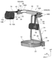
- the arm assist device 10 which is an example of the embodiment of the present invention will be described with reference to FIGS. 1 to 8.
- the arrow FR indicates the front side of the human body
- the arrow UP indicates the upper side of the human body
- the arrow W indicates the left-right direction of the human body.
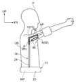
- FIG. 1 shows a side view of the wearer P wearing the arm assist device 10.
- the arm assist device 10 is attached to the upper body of the wearer P. Specifically, it supports the lumbar support portion 12 that supports the lumbar portion WP of the wearer P, the upper body support portion 14 that supports the upper body portion UB of the wearer P from the back side, and the upper arm portion AP of the wearer P. It is configured to include the upper arm support portion 16.
- a waist belt 22 as a band formed in a band shape along the outer circumference of the waist WP of the human body is arranged on the lower side of the upper body support portion 14 of the arm assisting device 10. ing.
- the waist belt 22 is configured so that the back side of the human body is fixed to the lower end of the upper body support portion 14 and the front side of the human body is provided with a detachable portion and a fixing portion (not shown) so that the waist belt 22 can be attached to the waist WP of the wearer P. There is.
- the waist belt 22 When the attachment / detachment portion is attached / detached, the waist belt 22 is wound around the waist WP of the wearer P, and the wound waist belt 22 is used as a work clothes or the like worn by the wearer P or the wearer P via the fixed portion. It is fixed to the clothes. Further, the length of the waist belt 22 can be adjusted. Therefore, the waist belt 22 is securely attached to the waist WP of the wearer P by adjusting its length. As a result, the arm assist device can be stably attached to the wearer P.
- the upper body support portion 14 On the upper side of the human body of the lumbar support portion 12, a metal upper body support portion 14 that supports the upper body portion UB of the wearer P from the back surface side is arranged.
- the upper body support portion 14 is a frame portion 24 formed in a substantially inverted V shape when viewed from the front of the human body by a substantially cylindrical pipe material, and both ends (lower end portions) of the frame portion 24 on the lower side of the human body in the left-right direction of the human body. It is configured to include a slide portion 26 formed so as to be slidable along the vertical direction of the human body, and a frame mounting portion 28 fixed to the back side of the human body of the waist belt 22 and into which the slide portion 26 is inserted. ing.
- the frame mounting portion 28 is formed in a substantially square tubular shape that is open in the vertical direction of the human body, and both ends of the human body in the left-right direction on the front side of the human body are fixed to the back side of the human body of the waist belt 22. Further, on the inner peripheral side of both ends of the frame mounting portion 28 on the front side of the human body in the left-right direction of the human body, a substantially cylindrical frame insertion portion 30 formed so that the lower end portion of the frame portion 24 can be inserted is provided as a frame mounting portion. It is integrally formed with 28. On the inner peripheral side of the frame mounting portion 28, a hole extending outward in the radial direction is formed.
- a substantially rod-shaped pin (not shown) that can be projected inward in the radial direction from the hole by attaching a spring or the like and can be buried inside the hole by an external force.
- a provided pin locking portion 32 is provided.
- the slide portion 26 has an insertion portion 34 having a hole formed inward in the radial direction in a portion facing the pin locking portion 32 on the outer peripheral portion when the slide portion 26 is inserted into the frame insertion portion 30. It has multiple along the direction. Therefore, when the insertion portion 34 of the slide portion 26 inserted into the frame insertion portion 30 and the pin locking portion 32 face each other, the pin of the pin locking portion 32 urged by a spring or the like moves to the insertion portion 34. It is projected toward and inserted into the insertion portion 34. As a result, the frame portion 24 is locked with respect to the frame mounting portion 28. Further, the frame mounting portion 28 includes a pull-in portion (not shown) for pulling the pin into the hole of the frame insertion portion 30 by operation.
- the engagement between the frame portion 24 and the frame mounting portion 28 can be disengaged, and the height of the frame portion 24 from the lumbar support portion 12 in the vertical direction of the human body can be changed. This makes it possible to adjust the height of the upper body support portion according to the body shape of the person who wears the arm assist device.
- the pin locking portion 32 has been described as having a pin urged by a spring or the like to be inserted into the insertion portion 34, but the present invention is not limited to this, and the frame portion is referred to the frame mounting portion by another embodiment. May be locked.
- the pin locking portion may be locked by a rod-shaped member such as a pin manually inserted from the outside of the frame mounting portion into a hole formed through the frame mounting portion to the frame insertion portion. ..
- the arm portions 36 are a substantially box-shaped arm central portion 36A arranged at the upper end of the frame portion 24 substantially in the center of the human body in the left-right direction, and a pair of left and right arm portions 36A that are expandable and contractible along the human body left-right direction. It is equipped with an arm 36B.
- the pair of left and right arms 36B include a plurality of (two) arms 36B on the right side of the human body and the left side of the human body.
- Each pair of left and right arms 36B is formed in a substantially L-shape in a plan view curved from the lateral side of the shoulder of the human body to the front side of the human body on the outside in the left-right direction of the human body.
- the tip of the side curved toward the front side of the human body is connected to a member support portion 18 described later. Therefore, by adjusting the length of the arm 36B according to the body shape (shoulder width) of the wearer P, the member support portion 18 can be arranged at an appropriate position on the side side of the upper arm portion AP of the wearer P. it can.
- the member support portion 18 A pair of left and right metal member support portions 18 arranged on the lateral side of the upper arm of the wearer P are connected to the front end of the pair of left and right arms 36B. As shown in FIG. 2, the member support portion 18 has a substantially box-shaped outer peripheral shape. At the upper end of the member support portion 18, an upper surface portion 42 extending in the front-rear direction of the human body and formed in a substantially plate shape is formed, and at the lower end portion, an upper surface portion 42 extending in the front-rear direction of the human body and having a substantially plate shape is formed. The lower surface portion 44 formed in the above is formed. Further, a pair of metal plates 46 are attached to both side portions of the member support portion 18 in the left-right direction of the human body so as to cover both side portions of the member support portion 18.
- FIG. 3 shows a member support portion 18 from which the pair of metal plates 46 has been removed.
- An elliptical plate 48 on the upper surface which is formed in a substantially elliptical shape in a plan view, is attached to the upper end of the upper surface 42 on the upper side of the human body and on the back side of the human body.
- a lower surface side elliptical plate 50 formed in a substantially elliptical shape in a plan view is attached to an end portion of the lower surface portion 44 on the lower side of the human body and on the back surface side of the human body.
- a shaft-shaped back side shaft portion 52 is arranged along the vertical direction of the human body from the upper surface portion 42 to the lower surface portion 44.
- the upper surface side elliptical plate 48 is rotatably attached to the upper end portion of the back surface side shaft portion 52 penetrating the upper surface portion 42 in the left-right direction of the human body.
- the lower surface side elliptical plate 50 is rotatably attached to the lower end portion of the back surface side shaft portion 52 penetrating the lower surface portion 44 in the left-right direction of the human body.
- a shaft-shaped fixed shaft portion 54 formed along the vertical direction of the human body is fixed between the human body back side and the lower surface side of the upper surface side elliptical plate 48 and the human body back side and the upper surface side of the lower surface side elliptical plate 50.
- the front end of the human body of the plurality of (two) arms 36B is joined to the rear end of the upper surface side elliptical plate 48 and the lower surface side elliptical plate 50, respectively. Therefore, the member support portion 18 can be rotated in the left-right direction of the human body with respect to the arm 36B. As a result, the member support portion 18 can be arranged according to the body shape of the wearer P.
- a metal variable portion 60 having a substantially rectangular parallelepiped outer peripheral shape is arranged inside the member support portion 18.
- a front hole 60A is formed through the end of the variable portion 60 on the front surface side of the human body along the vertical direction of the human body.
- a rear hole portion 60B is formed through the end portion of the variable portion 60 on the back surface side of the human body along the vertical direction of the human body.
- a shaft-shaped front side shaft portion 56 arranged along the vertical direction of the human body from the upper surface portion 42 to the lower surface portion 44 is inserted into the front side hole portion 60A of the variable portion 60 on the front side of the human body of the member support portion 18. ing.
- a rear shaft portion 52 is inserted through the rear hole portion 60B of the variable portion 60.
- the inner diameter of the front hole portion 60A is formed to be larger than the outer diameter of the front side shaft portion 56
- the inner diameter of the rear side hole portion 60B is formed to be larger than the outer diameter of the back side shaft portion 52.
- a pair of extension portions 64 formed in a substantially triangular plate shape with the left and right directions of the human body as the out-of-plane direction are formed at the front end of the variable portion 60.
- the pair of extension portions 64 are formed at intervals in the left-right direction of the human body.
- each extension portion 64 is formed with a pair of mounting holes 66 penetrating along the left and right directions of the human body.
- the pair of mounting holes 66 are formed along the same axis along the left-right direction of the human body, and the inner peripheral shape is formed in the same circular shape when viewed from the side of the human body.
- a pair of front-side mounting members 70 formed in a substantially triangular plate shape with the left-right direction of the human body as the out-of-plane direction are arranged.
- the two apex portions on the back side of the human body are bolted to the upper surface portion 42 and the lower surface portion 44, respectively.
- a substantially columnar first shaft portion 72 arranged along the left-right direction of the human body is vertically arranged between the pair of front mounting members 70. ing.
- a pair of auxiliary members 74 formed in a substantially elliptical plate shape when viewed from the side of the human body is provided at both ends of the first shaft portion 72 penetrating between the front mounting members 70 in the left-right direction of the human body.
- the first shaft portion 72 is rotatably attached in the vertical direction of the human body as a rotation axis.
- a pair of first members 76 extending toward the front side of the human body are attached to the first shaft portion 72.
- the pair of first members 76 are configured to be rotatable in the vertical direction of the human body with the first shaft portion 72 as a rotation axis.
- a substantially columnar first auxiliary shaft 78 formed along the left-right direction of the human body is penetratingly arranged.
- the other end of the pair of auxiliary members 74 is fixed to both ends of the first auxiliary shaft 78 in the left-right direction of the human body.
- gas springs 80 as urging means are arranged along the pair of first members 76.
- the front end (elbow side) as one end is rotatably attached to the first member 76 in the vertical direction of the human body, and the rear end (shoulder side) as the other end.
- the elbow-side end of the gas spring 80 rotates in the vertical direction of the human body with a shaft-shaped second auxiliary shaft 82 penetrating the pair of first members 76 along the left-right direction of the human body. It is installed as possible.
- the shoulder-side end of the gas spring 80 can be rotated in the vertical direction of the human body by a substantially cylindrical second shaft portion 84 arranged between the mounting holes 66 of the pair of extension portions 64 of the variable portion 60. It is attached.
- the end of the gas spring 80 is rotatably attached to the first member 76 in the vertical direction of the human body, and the end of the shoulder side is rotatably attached to the variable portion 60 in the vertical direction of the human body. There is. Therefore, as will be described later, a moment around the first shaft portion 72 is generated by the urging force generated by the expansion and contraction of the gas spring 80.
- the moment lever here corresponds to the length of the perpendicular line drawn from the first shaft portion 72 to the gas spring 80 when viewed from the side of the human body.
- the position where the first shaft portion 72 and the gas spring 80 are in the same linear shape when viewed from the side of the human body is the neutral point.
- the neutral point here means a point at which a moment around the first shaft portion 72 does not occur because the urging force of the gas spring 80 and the direction of the moment lever match.
- the direction of the urging force of the gas spring 80 is reversed between the front side of the human body and the rear side of the human body with the neutral point as a boundary, the rotation direction of the moment is also reversed.
- a stopper 86 is formed on the front side of the lower surface portion 44 of the member support portion 18 formed in a substantially plate shape on the front side of the human body. Therefore, the first shaft portion 72 that rotates to the rear side of the human body by crossing the neutral point is stopped by the stopper 86. As a result, it is possible to prevent or suppress the upper arm AP from rotating to the rear side of the human body beyond the neutral point.
- a knurled screw 90 as an adjusting portion is inserted inward from a hole formed through the upper surface portion 42 on the upper surface portion 42 side of the member support portion 18.
- the shaft portion 90B of the knurled screw 90 is screwed into the female screw portion 60C formed in the variable portion 60, and the tip thereof is arranged inside a hole (not shown) formed in the lower surface portion 44. Therefore, by rotating the head 90A of the knurled screw 90, the variable portion 60 can be moved to the upper side of the human body or the lower side of the human body inside the member support portion 18. Further, by using the knurled screw 90, the position of the variable portion 60 in the member support portion 18 in the vertical direction of the human body can be changed steplessly.
- the upper arm support portion 16 is rotatably attached to the first member 76 in the vertical direction of the human body at an end on the elbow side as one end of the first member 76.
- the upper arm support portion 16 includes a pair of side members 16A arranged so as to face both side portions of the upper arm portion AP, and a back surface side member 16B that abuts on the back surface side of the upper arm portion AP.
- the pair of side members 16A are arranged so as to face both side portions of the upper arm portion AP and are rotatably attached to the first member 76 on the outer side in the left-right direction of the human body in the vertical direction of the human body around the axis along the left-right direction of the human body.
- the front side of the upper arm portion AP of the upper arm support portion 16 is open so that the upper arm of the wearer P can be directly fitted.
- the gas spring 80 is arranged along the upper arm AP.
- One end (the end on the elbow side) of the gas spring 80 is rotatably attached to the first member 76 around the axis along the left-right direction of the human body in the vertical direction of the human body.
- the other end portion (end portion on the shoulder side) can rotate in the vertical direction of the human body with the second shaft portion 84 provided on the extension portion 64 of the variable portion 60 with the axial direction in the left-right direction of the human body as a rotation axis. It is attached.
- the wearer P rotates the arm toward the front side of the human body, that is, when the arm is lifted, the first member 76 rotates forward around the first shaft portion 72 and the gas spring 80.
- the elbow-side end of the body moves to the front side of the human body. Therefore, the distance from the elbow-side end to the shoulder-side end of the gas spring 80, that is, the length of the gas spring 80 changes, and the first member receives the first auxiliary force. A moment around the shaft portion 72 is generated (acts). As a result, the workability of the wearer can be improved.
- the moment lever M of the moment can be calculated based on the mechanical model schematically shown in FIGS. 4 and 5.
- FIG. 4 the state in which the arm is extended along the horizontal direction of the human body is set to 0 degree, and the wearer P who lifts the upper arm portion AP by an angle ⁇ (see FIG. 5), the first member 76, the variable portion 60, and the variable portion 60.
- the positional relationship of the gas spring 80 as viewed from the side surface of the human body is schematically shown.
- the position (point) where the gas spring 80 is attached to the second shaft portion 84 is designated as a point A
- the position (point) where the gas spring 80 is attached to the second auxiliary shaft 82 is designated as a point B.
- the position (point) where the first shaft portion 72 is provided is defined as the point C.
- FIG. 5 shows an enlarged view of the schematic positional relationship shown in FIG.
- D represents the length of the gas spring 80
- E represents the length of the auxiliary line L2 drawn from the point B to the straight line L1 along the extending direction of the first member 76
- F represents the straight line. It represents the distance from the intersection of L2 and the straight line L1 to the point A.
- x represents the distance between the point B and the point C in the extending direction of the first member 76
- y represents the distance between the point B and the point C in the direction orthogonal to the extending direction of the first member 76.
- FIG. 6 shows a graph showing the relationship between the rotation angle of the upper arm AP and the assisting force obtained by the arm assisting device.
- the horizontal axis shows the rotation angle of the upper arm AP.
- the rotation angle of the upper arm AP is defined as 0 degrees when the upper arm AP is extended along the horizontal direction of the human body, and positive when the upper arm AP is lifted upward of the human body.
- the vertical axis shows the moment as an auxiliary force.
- FIG. 6 shows the moments of the three cases in which the position of the variable portion 60 is changed by using the knurled screw 90.
- variable portion 60 when the variable portion 60 is moved to the upper side of the human body of the member support portion 18 and brought closer to the first shaft portion 72, it is moved to the lower side of the human body of the member support portion 18 from the first shaft portion 72.
- C2 when they are far away and C3 when they are positioned substantially in the middle of the human body in the vertical direction of the member support portion 18. From these facts, it is possible to increase or decrease the range of the moment generated by the assisting force by moving the variable portion 60 inside the member support portion 18 to change the distance r between the first shaft portion 72 and the second shaft portion 84. Recognize. Thereby, the range of the moment for assisting the rotation of the upper arm AP can be changed.
- the member support portion 18 includes a variable portion 60 capable of changing the distance from the first shaft portion 72 and a variable portion 60 in the member support portion 18 by operation.
- a knurled screw 90 for changing the position is provided. Therefore, by changing the position of the variable portion 60 in the member support portion 18, the shoulder-side end portion of the gas spring 80 rotatably attached to the variable portion 60 can be moved.
- the shoulder end of the gas spring 80 By moving the shoulder end of the gas spring 80, the distance from the first shaft portion 72 to the gas spring 80, that is, the length of the perpendicular line drawn from the first shaft portion 72 to the gas spring 80 when viewed from the side of the human body Because of the change, the moment lever of the moment generated by the gas spring 80 changes. Thereby, the range of the moment for assisting the rotation of the upper arm AP can be changed without replacing the gas spring 80.
- the knurled screw 90 is used for the adjusting portion, the position of the variable portion 60 in the member support portion 18 in the vertical direction of the human body can be changed steplessly. Thereby, the range of the moment as the auxiliary force can be appropriately changed according to the work purpose.
- FIG. 7 shows a state in which the arm assisting device 10 is in the neutral point.
- the gas spring 80 reverses the urging direction to the rear side of the human body when it exceeds the neutral point, so that the upper arm AR is rotated to the rear side of the human body. At that time, a moment is generated to rotate the upper arm AR toward the rear side of the human body.
- the member support portion 18 is provided with a stopper 86 on the lower surface portion 44 for stopping the first member 76 against the rotation of the upper arm portion AR of the wearer P toward the rear side of the human body. Therefore, for example, even when the variable portion 60 is adjusted so that the moment becomes stronger, as shown in FIG.
- the upper arm portion AR is prevented or suppressed from rotating toward the rear side of the human body with a strong moment. can do. Further, since the auxiliary force is not generated at the neutral point where the urging direction of the moment is reversed, for example, by setting the state where the first member 76 is arranged along the vertical direction of the human body as the neutral point, the arm The wearer P of the part auxiliary device 10 can easily wear the upper arm part AP in a lowered state.
- the first member 76 is attached to the pair of side members 16A of the upper arm support portion 16 in which the front side of the upper arm portion AP is open, on the outer side in the left-right direction of the human body. ing. Therefore, even when the front side of the upper arm AP is open, the pair of side members 16A and the back member 16B can stably hold the upper arm AP. Further, since the front side of the upper arm AP is open, the arm assist device 10 can be easily attached and detached, and since the upper arm AP is not restrained, the wearer P can easily operate the knurled screw 90. You can do things.
- the arm assisting device 10 can change the range of assisting force for assisting the rotation of the arm without replacing the gas spring 80.
- an arm portion 36 whose length in the left-right direction of the human body can be adjusted is arranged on the upper side of the upper body support portion 14 of the human body. Therefore, by adjusting the length of the arm 36B according to the body shape of the wearer P, the member support portion 18 and the first member 76 attached to the member support portion 18 are placed at appropriate positions on the side of the upper arm portion AP of the wearer P. It can be placed on the other side. As a result, the upper arm AP of the wearer P can be appropriately assisted.
- the upper body support portion 14 is formed in a band shape along the waist circumference direction of the wearer P on the lower side of the human body, and the waist of the wearer P is formed.
- a waist support portion 12 that can be fixed to the waist is arranged. Therefore, the arm assist device 10 provided with the member support portion 18 can be stably attached to the wearer P. As a result, the upper arm AP can be appropriately assisted while the upper body UB of the wearer P is stably held.
- the upper body support portion 14 includes a slide portion 26 whose height can be adjusted in the vertical direction of the human body. Therefore, by adjusting the height of the upper body support portion 14 according to the body shape of the wearer P, the arm assist device 10 provided with the member support portion 18 can be mounted on the wearer P at an appropriate position. it can. As a result, an auxiliary force can be appropriately applied to the upper arm of the wearer P.
- the state in which the wearer P wearing the arm assisting device 100 as an example according to the present embodiment has his arms extended along the horizontal direction of the human body is set to 0 degrees, and the angle ⁇ is upward from there.
- the positional relationship of the first member 76, the variable portion 60, and the gas spring 80 as viewed from the side surface side of the human body when the upper arm portion AP is lifted is schematically shown.
- the variable portion 60 is provided with an extension portion 164 extending to the front side (elbow side) of the human body with respect to the extension portion 64 of the first embodiment.
- the third shaft portion 184 which is attached to the extension portion 164 along the left-right direction of the human body and to which the shoulder-side end portion of the gas spring 80 is connected, has a predetermined length t from the position in the first embodiment. It is located on the front side (elbow side) of the human body.
- the moment lever M of the moment can be calculated based on the mechanical model schematically shown in FIG.
- the position (point) where the gas spring 80 is attached to the third shaft portion 184 is defined as a point A
- the position (point) where the gas spring 80 is attached to the second auxiliary shaft 82 is defined as a point B
- the position (point) where the first shaft portion 72 is provided is defined as the point C.
- the length D of the gas spring 80 is based on two similar triangles including the angle ⁇ in FIG.
- D2 ⁇ r + s ⁇ sin ( ⁇ - ⁇ ) ⁇ 2 + ⁇ s ⁇ cos ( ⁇ - ⁇ ) -t ⁇ 2 It is represented by.
- x represents the distance between the point B and the point C in the extending direction of the first member 76
- y represents the distance between the point B and the point C in the direction orthogonal to the extending direction of the first member 76.
- the moment as an auxiliary force can be increased by providing the variable portion 60 with an extension portion 164 extending to the front side of the human body and moving the third shaft portion 184 to the elbow side. Thereby, the range of the moment for assisting the rotation of the upper arm AP can be changed.
- the other end (shoulder side end) of the gas spring 80 is an extension portion extending from the variable portion 60 toward the elbow side of the wearer P.
- the third shaft portion 184 provided with the axial direction in the left-right direction of the human body is rotatably attached in the vertical direction of the human body as a rotation axis. Therefore, the position of the third shaft portion 184, which is the position of the other end portion of the gas spring 80, moves to the front side of the human body from the variable portion 60, and the distance between the first shaft portion 72 and the gas spring 80 changes. Thereby, the range of the moment as an auxiliary force for assisting the rotation of the arm can be adjusted in a wider range without replacing the gas spring 80.
- FIG. 10 is a side view showing a state in which the arm assist device 200 is attached to the wearer P.
- FIG. 11 is a front view showing a state in which the arm assist device 200 is attached to the wearer P.
- FIG. 12 is a rear view showing a state in which the arm assist device 200 is attached to the wearer P.
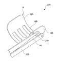
- FIG. 13 is a partially enlarged perspective view showing the periphery of the upper arm support portion 16 of the arm assist device 200.
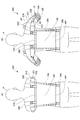
- 14A and 14B are rear views showing a state in which the arm assist device 200 is attached to the wearer P, FIG. 14A shows a state in which the length of the upper body support portion 250 is increased, and FIG. 14B shows a state in which the upper body support portion 250 is attached. A state in which the length of the portion 250 is shortened is shown.
- 15A and 15B are rear views showing a state in which the arm assisting device 200 is attached to the wearer P, FIG. 15A shows a state in which the back connecting member 270 is extended with the arm facing forward, and FIG. 15B shows an arm.
- FIG. 16 is a perspective view illustrating attachment / detachment of the arm assist device 200 to / from the wearer P
- FIG. 16A shows a state in which the upper arm support portion 16 is connected to the shoulder belt 280 by a hook-and-loop fastener 290.
- the arm assist device 200 shown in FIGS. 10 to 12 is configured to be symmetrical, and is attached to the upper body of the wearer P by being worn by the wearer P on his back like a backpack. Rucksack.
- the arm assisting device 200 generates an assisting force by a gas spring (urging means) 80 for each of the loads of both arms of the wearer P.
- the arm assist device 200 includes a pair of left and right member support portions 210, a pair of left and right first members 220, a pair of left and right upper arm support portions 16, and a pair of left and right rotation limiting members 230 (FIG. 13, etc.). (See), a pair of left and right gas springs 80, a pair of left and right lock mechanisms (not shown), a pair of left and right arm portions 240, a pair of left and right upper body support portions 250, a band portion 260, and a back connecting member 270.
- a pair of left and right shoulder belts 280, a strap 285, a pair of left and right hook-and-loop fasteners (fixing tools) 290, and the like are provided.
- the pair of left and right member support portions 210 are attached to each of the pair of left and right upper body support portions 250 that support the upper body of the wearer P from the back side via each of the pair of left and right arm portions 240. As a result, the wearer P is arranged on the side of the left and right upper arms.
- the pair of left and right member support portions 210 support the first member 220 and the gas spring 80 arranged along the upper arm on their base end sides, respectively.
- the pair of left and right first members 220 are arranged along the lateral side of the upper arm, respectively, and the first shaft portion 221 (FIGS. 14, 15, and 15) is provided on the member support portion 210 with the axial direction in the left-right direction of the human body. It is possible to rotate the human body in the vertical direction around the rotation axis (see 19 etc.).
- Each of the pair of left and right first members 220 has an upper arm support portion 16 that supports the upper arm attached to the tip thereof.
- the upper arm support portion 16 is rotatably attached to the tip of the first member 220 with the axial direction in the left-right direction of the human body.
- the upper arm support portions 16 are arranged so as to face both side portions of the upper arm and are rotatably attached to the first member 220 on the lateral side of the human body in the vertical direction of the human body around an axis along the horizontal direction of the human body.
- a pair of side members 16A and a back side member 16B formed over the rear end of the pair of side members 16A and abutting the back side of the upper arm are provided, and the front side of the upper arm is open.
- the upper arm support portion 16 is restricted from rotating in the upward direction of the human body from a predetermined position by the rotation limiting member 230.
- the upper arm support portion 16 is covered with a cushioning cover 16C (see FIGS. 16A and 16B), as will be described later.
- the rotation limiting member 230 restricts the rotation of the upper arm support portion 16 from a predetermined position in the upward direction of the human body.
- the rotation limiting member 230 is a pin attached to the side member 16A on the first member 220 side of the upper arm support portion 16, and the rotation of the upper arm support portion 16 is caused by abutting on the first member 220. Restrict.
- the pair of left and right gas springs 80 are respectively arranged below the first member 220 along the lateral side of the upper arm, and the tip, which is one end, moves in the vertical direction of the human body around the axis along the left and right direction of the human body.
- a second shaft portion 222 that is rotatably attached to the tip of the first member 220 and whose base end, which is the other end, is provided directly on the member support portion 210 with the axial direction in the left-right direction of the human body. It is attached so that it can rotate in the vertical direction of the human body as a rotation axis.
- the pair of left and right gas springs 80 urge the arm of the wearer P. Details of the urging of the arm of the wearer P by the gas spring 80 will be described later.
- the pair of left and right lock mechanisms are mechanisms for stopping the first member 220 with respect to the rotation of the wearer P's arm toward the rear side of the human body.
- the pair of left and right arm portions 240 are formed on the upper side of each of the pair of left and right upper body support portions 250 along the left and right directions of the human body, and the pair of left and right member supports from the side of the shoulder of the wearer P. It is connected to each of the parts 210. More specifically, the arm portions 240 extend from the upper body support portion 250 so as to be separated from each other to the left and right, and are curved in the forward direction at predetermined positions, and surround the portion extending from the rear portion to the side portion of the deltoid muscle. It has such a shape.
- the pair of left and right upper body support portions 250 are provided on the lower side of each of the pair of left and right member support portions 210, and support the upper body of the wearer P from the back side.
- the pair of left and right upper body support portions 250 are arranged in pairs on the left and right sides along the vertical direction of the human body on the back side of the wearer P, and the band portions 260 have three degrees of freedom for rotation at their lower ends.
- the upper ends of each are connected to each other by a back connecting member 270 made of strip-shaped rubber.
- having three degrees of freedom for rotation means that it can rotate about an axis that is oriented in each of the three directions of the front-back direction, the left-right direction, and the up-down direction.
- the lower end of the upper body support portion 250 includes a circular end member 2505 provided with a spherical member (not shown) protruding forward fixedly provided.
- the spherical member (not shown) is a hole formed in the base metal fitting 2601 fixed to the band portion 260, and is fitted into a circular hole whose inside is wider than the opening.
- a spherical member (not shown) slides and rotates with respect to the base metal fitting 2601 inside the hole, so that the upper body support portion 250 has three degrees of freedom with respect to the base metal fitting 2601. , Supported by the base metal fittings 2601.
- the lengths of the pair of left and right upper body support portions 250 can be adjusted, respectively.
- a plurality of through holes are formed at equal intervals in the longitudinal direction of the upper body support portion 250, and an inner surface formed by an inner peripheral surface of the outer tube 2501.
- It has an inner tube 2502 that is arranged in space and slides in a coaxial positional relationship with the outer tube 2501.
- the inner tube 2502 is provided with a spherical member 2503 that is urged and protrudes to the outside of the inner tube 2502 by a spring (not shown).
- the inner tube 2502 is configured to be fixed to the outer tube 2501 by engaging the spherical member 2503 with the through hole of the outer tube 2501.
- the band portion 260 is formed in a band shape along the waist circumference direction of the wearer P, and can be fixed to the waist of the wearer P.
- the band portion 260 has a buckle 261 on the front side of the wearer P and is removable, and performs the same function as the waist belt of a general backpack.
- the back surface connecting member 270 connects the pair of left and right upper body support portions 250 to each other above each of the pair of left and right upper body support portions 250.
- the upper body of the wearer P is stretchably supported from the back side.
- the pair of left and right shoulder belts 280 are arranged in pairs on the left and right along the vertical direction of the human body, the lower end of each is attached to the front side of the human body in the band 260, and the upper end of each is attached to the back connecting member 270. ..
- Such a pair of left and right shoulder belts 280 perform the same function as a shoulder harness of a general backpack.
- the strap 285 connects a pair of left and right shoulder belts 280 to each other around the chest of the wearer P, and supports the upper body of the wearer P from the front side.
- This strap 285 has a buckle 286 and is removable, and performs the same function as a chest strap of a general backpack.
- the pair of left and right hook-and-loop fasteners 290 are attached to the cover 16C covering the pair of left and right upper arm support portions 16, respectively.
- Each of these pair of left and right hook-and-loop fasteners 290 attaches and detaches the upper arm support portion 16 to the shoulder belt 280 (see FIG. 16A), and is also detachably wrapped around the upper arm to attach the upper arm support portion 16 to the upper arm. Fix (see FIG. 16B).
- FIG. 17 is a schematic view showing the positional relationship between the arm assisting device 200 and the wearer P.
- the moment lever M of the moment generated by the gas spring 80 can be calculated based on the mechanical model shown in FIG.
- the position (point) where the gas spring 80 is attached to the second shaft portion 222 is defined as point A
- the position (point) where the gas spring 80 is attached to the tip of the first member 220 is defined as point B. ..
- a position (point) where the first member 220 is attached to the first shaft portion 221 is defined as a point C.
- the moment lever M corresponds to the length of the perpendicular line PL3 drawn from the first shaft portion 221 to the gas spring 80 when viewed from the side of the human body.
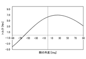
- FIG. 18 is a graph showing the relationship between the assisting force obtained by the arm assisting device 200 and the rotation angle of the arm.
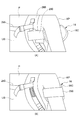
- 19A and 19B are side views showing the arm assisting device 200, in which FIG. 19A shows a state of being positioned at a positive angle, FIG. 19B shows a state of being positioned at -60 degrees, and FIG. 19C shows a state of being located at ⁇ 90 degrees. Indicates a state located at a right angle. It should be noted that the illustration of the configuration unnecessary for the description will be omitted as appropriate.
- the horizontal axis shows the rotation angle of the upper arm portion.
- the rotation angle of the upper arm is defined as 0 degrees when the upper arm is extended along the horizontal direction of the human body, and positive when the upper arm is lifted upward of the human body.
- the vertical axis shows the moment as an auxiliary force.
- the torque for urging the arm of the wearer P by the gas spring 80 is a negative value (-4.0 [Nm]) at ⁇ 90 degrees and is neutral at ⁇ 60 degrees.
- the maximum positive value 7.0 [N ⁇ m]
- it is a positive value (3.5 [Nm])
- the value fluctuates smoothly as it fluctuates in the range of ⁇ 90 degrees to 90 degrees.
- FIG. 19A when the first member 220 is located at a positive angle, an upward auxiliary force is generated.
- FIG. 19B when the first member 220 is located at the neutral point of ⁇ 60 degrees, no auxiliary force is generated.
- FIG. 19C when the first member 220 is located at ⁇ 90 degrees, an auxiliary force is generated toward the rear side of the human body, but the first member 220 is locked by a locking mechanism (not shown). Can be stopped.
- the arm assisting device 200 is provided on the member support portion 210 arranged on the side side of the upper arm of the wearer P and on the lower side of the human body of the member support portion 210, and the upper body of the wearer P is placed on the back surface.
- the upper body support portion 250 that supports from the side and the first shaft portion 221 that is arranged along the upper arm and is provided on the member support portion 210 with the axial direction in the left-right direction of the human body can be rotated in the vertical direction of the human body.
- the first member 220 and the upper arm support portion 16 which is attached to one end of the first member 220 and supports the upper arm and is arranged along the upper arm, and one end is attached to the first member 220 of the human body.
- the second shaft portion 222 is rotatably attached in the vertical direction of the human body around the axis along the left-right direction, and the other end is provided directly on the member support portion 210 with the axial direction in the left-right direction of the human body. It is configured to include a gas spring 80 that is rotatably attached in the vertical direction of the human body and urges the arm of the wearer P.
- the gas spring 80 is arranged along the upper arm.
- One end of the gas spring 80 is rotatably attached to the first member 220 in the vertical direction of the human body around an axis along the horizontal direction of the human body.
- the other end portion is directly attached to the member support portion 210 so as to be rotatable in the vertical direction of the human body with the second shaft portion 222 provided with the axial direction in the left-right direction of the human body as a rotation axis.
- the distance from one end of the gas spring 80 to the other end that is, the length of the gas spring 80 changes, and an urging force is generated accordingly. Due to this urging force, a moment around the first shaft portion 221 acts on the first member 220.
- the moment lever is determined by the distance from the first shaft portion 221 to the gas spring 80.
- the length of the perpendicular line drawn from the first shaft portion 221 to the gas spring 80 in the side view of the human body corresponds to the moment lever.
- the case where the arm of the wearer P is extended horizontally is set to 0 degree, and the case where the arm of the wearer P is lifted upward is set.
- the torque for urging the arm of the wearer P by the gas spring 80 is a negative value at -90 degrees and a maximum value at a predetermined angle of more than 0 degrees and less than 90 degrees. It is a positive value, which is a positive value in the case of 90 degrees, and the value fluctuates smoothly as it fluctuates in the range of ⁇ 90 degrees to 90 degrees.
- the torque for urging the arm of the wearer P by the gas spring 80 is a negative value when it is ⁇ 90 degrees, and is a predetermined angle exceeding 0 degrees and less than 90 degrees.
- the assisting force is not generated at the neutral point where the assisting force is reversed, the wearer P who wears the arm assisting device can easily wear the arm assisting device in the neutral point state.
- the auxiliary force has a negative value in the range closer to -90 degrees than the neutral point, when the wearer P tries to reach downward, such as when picking up something dropped on the floor, It is possible to avoid hindering the upward assisting force and make it easy to reach.
- the arm assist device 200 is provided with a lock mechanism (not shown) for stopping the first member 220 with respect to the rotation of the wearer P's arm toward the rear side of the human body.
- the arm is provided with a lock mechanism (not shown) for stopping the first member 220 with respect to the rotation of the arm of the wearer P toward the rear side of the human body. It is possible to prevent or suppress rotation to the rear side of the human body with a strong auxiliary force.
- the arm assisting device 200 is formed in a band shape along the waist circumference direction of the wearer P, and includes a band portion 260 that can be fixed to the waist of the wearer P, and the upper body support portion 250 is the upper and lower parts of the human body. It is arranged in pairs on the left and right along the direction, and each lower end is attached to the band 260 so as to have three degrees of freedom for rotation.
- the upper body support portions 250 are arranged in pairs on the left and right along the vertical direction of the human body, and each lower end has three degrees of freedom for rotation. Since it is attached to the band portion 260, the upper body support portion 250 can be flexibly moved with respect to the band portion 260 fixed to the waist.
- the length of each pair of upper body support portions 250 can be adjusted.
- the length of each pair of upper body support portions 250 can be adjusted, so that the length of the pair of upper body support portions 250 is adjusted according to the height of the wearer P.
- the length of the upper body support portion 250 can be adjusted to adjust the position of the band portion 260 fixed to the waist.
- the arm assisting device 200 connects the paired upper body supporting portions 250 to each other above each of the paired upper body supporting portions 250, and supports the upper body of the wearer P stretchably from the back side. It includes a connecting member 270.
- the pair of upper body support portions 250 can be connected to each other above the pair of upper body support portions 250, and the upper body of the wearer P can be expanded and contracted from the back side. Since the back connecting member 270 is provided to support the back connecting member 270, the back connecting member 270 can be expanded and contracted by extending the arm forward or laterally, and the pair of upper body support portions 250 can be flexibly moved.
- the arm assisting devices 200 are arranged in pairs on the left and right along the vertical direction of the upper body, the lower ends of each are attached to the front side of the human body in the band portion 260, and the upper ends of each are attached to the back connecting member 270. It is equipped with a shoulder belt 280.
- the wearer P uses the arm assist device 200 like a backpack. You can carry it on your back and wear it by yourself.
- the arm assist device 200 is provided with a hook-and-loop fastener 290 that attaches the upper arm support portion 16 to the shoulder belt 280 so as to be detachably attached and that fixes the upper arm support portion 16 to the upper arm by being detachably wrapped around the upper arm.
- the wearer P attaches the arm assist device 200.
- the hook-and-loop fastener 290 can be easily wrapped around the upper arm after being attached.
- the upper arm support portions 16 are arranged so as to face both side portions of the upper arm, and on the outer side in the left-right direction of the human body, the first member 220 is attached to the first member 220 in the vertical direction of the human body along the axis along the left-right direction of the human body.
- a pair of side members 16A rotatably attached to the upper arm, and a back side member 16B formed over the rear end of the pair of side members 16A and abutting on the back side of the upper arm.
- the front side is open, and the arm assisting device 200 includes a rotation limiting member 230 that limits the rotation of the upper arm supporting portion 16 in the upward direction of the human body from a predetermined position.
- the rotation limiting member 230 for limiting the rotation of the upper arm supporting portion 16 in the upward direction of the human body from a predetermined position is provided, the upper arm supporting portion 16 is disengaged from the arm. It is possible to prevent the upper arm from rotating independently of the arm, and the upper arm support portion 16 can always be in contact with the upper arm.
- the arm assist device 200 is formed on the upper side of the upper body support portion 250 along the left-right direction of the human body, and the arm portion 240 connected to the member support portion 210 from the side side of the shoulder of the wearer P. I have.
- FIG. 20 is a rear view showing a modified example of the arm assisting device according to the third embodiment.
- the distance maintaining member 263A has a width shorter than the width of the band portion 260 in the vertical direction, surrounds the periphery of the left and right base metal fittings 2601, and is hung on the left and right base metal fittings 2601. It is provided along the rear surface of the band portion 260.
- the distance maintaining member 263A is made of a metal plate member, and in the present embodiment, it is made of, for example, an aluminum alloy plate member.
- the distance maintaining member 263A has a strip-shaped plate shape that is long in the left-right direction, and the left and right end portions 2631A form an obtuse angle in the forward direction with respect to the central portion 2632A. It is bent at.
- notches 2633A are formed from the upper end to the center in the vertical direction.
- the left and right ends of the distance maintaining member 263A are formed by four bolts 2635A arranged so as to surround the base metal fittings 2601. It is fixed to the band portion 260.
- a predetermined gap is formed between the band portion 260 and the distance maintaining member 263A.
- the gas spring 80 is used as the urging means, the present invention is not limited to this, and other urging means such as a spring may be used.
- Arm assist device 14 Upper body support 16 Upper arm support 16A Side member 16B Back side member 16C Cover 18 Member support 26 Slide part 36 Arm part 60 Variable part 64 Extension part 72 First shaft part 76 First member 80 Gas Spring (bringing means) 84 2nd shaft 86 Stopper 90 Knurled screw (adjustment) 100 Arm Auxiliary Device 164 Extension 184 Third Shaft 200 Arm Auxiliary Device 210 Member Support 220 First Member 221 First Shaft 222 Second Shaft 230 Rotation Restriction Member 240 Arm 250 Upper Body Support 260 Band 261 Buckle 270 Back connecting member 280 Shoulder belt 285 Strap 286 Buckle 290 Hook-and-loop fastener (fixing tool) P Wearer AP Upper arm UB Upper body WP Lumbar
Landscapes
- Engineering & Computer Science (AREA)
- Robotics (AREA)
- Mechanical Engineering (AREA)
- Manipulator (AREA)
Abstract
Description
図1には、腕部補助装置10を装着した装着者Pの側面図が示されている。腕部補助装置10は、装着者Pの上半身に装着される。具体的には、装着者Pの腰部WPを支持する腰部支持部12と、装着者Pの上体部UBを背面側から支持する上体支持部14と、装着者Pの上腕部APを支持する上腕支持部16と、を含んで構成されている。
図2に示されるように、腕部補助装置10の上体支持部14の人体下方側には、人体の腰部WPの外周に沿って帯状に形成された帯部としての腰ベルト22が配置されている。腰ベルト22は、その人体背面側が上体支持部14の下端部に固定されると共に、人体前面側に図示しない着脱部及び固定部を備えて装着者Pの腰部WPに取付可能に構成されている。着脱部が脱着されることにより、装着者Pの腰部WPに腰ベルト22が巻かれ、巻かれた腰ベルト22は、固定部を介して装着者P又は装着者Pが着用する作業着等の着衣に固定される。また、腰ベルト22は、長さ調節が可能とされている。このため、腰ベルト22は、その長さを調節することにより、装着者Pの腰部WPに確実に装着される。これにより、腕部補助装置を安定して装着者Pに装着させることができる。
腰部支持部12の人体上方側には、装着者Pの上体部UBを背面側から支持する金属製の上体支持部14が配置されている。上体支持部14は、略円筒状のパイプ材により、人体正面視で略逆V字状に形成されたフレーム部24と、フレーム部24の人体下方側の人体左右方向両端部(下端部)に人体上下方向に沿ってスライド可能に形成されたスライド部26と、腰ベルト22の人体背面側に固定されると共に内部にスライド部26が挿通されるフレーム取付部28と、を含んで構成されている。
上体支持部14の人体上方側には、装着者Pの肩幅に合わせて上腕支持部16の人体左右方向の長さを調整可能に構成された金属製のアーム部36が配置されている。アーム部36は、人体左右方向略中央においてフレーム部24の上端に配置された略箱状のアーム中央部36Aと、アーム中央部36Aから人体左右方向に沿って伸縮可能に構成された左右一対のアーム36Bを備えている。左右一対のアーム36Bは、人体右側と人体左側で各々複数(2本)のアーム36Bを備える。
左右一対のアーム36Bの人体前方側端部には、装着者Pの上腕の側方側に配置された金属製の左右一対の部材支持部18が連結されている。図2に示されるように、部材支持部18は、外周形状が略箱状に形成されている。部材支持部18の上端部には、人体前後方向に延在されると共に略板状に形成された上面部42が形成され、下端部には、人体前後方向に延在されると共に略板状に形成された下面部44が形成されている。また、部材支持部18の人体左右方向の両側部には、一対の金属板46が、部材支持部18の両側部を覆うように取り付けられている。
第1部材76の一方の端部としての肘側の端部には、上腕支持部16が、第1部材76に対して人体上下方向に回動可能に取り付けられている。上腕支持部16は、上腕部APの両側部に対向して配置された一対の側部材16Aと、上腕部APの背面側に当接する背面側部材16Bと、を備えて構成されている。一対の側部材16Aは、各々上腕部APの両側部に対向して配置されると共に人体左右方向外側において第1部材76に人体左右方向に沿った軸線回りに人体上下方向へ回動可能に取り付けられている。また、上腕支持部16の上腕部APの正面側は、装着者Pの上腕を直接嵌めることができるように開放されている。
次に、本実施形態の作用並びに効果について説明する。
M=r×cos(θ+β)
で表される。
D2={r+s×sin(θ-α)}2+{s×cos(θ-α)}2
で表される。sは、点Bと点Cの位置関係に基づき、s2=x2+y2で表される。ここで、xは、第1部材76の延在方向における点Bと点Cの距離、yは、第1部材76の延在方向と直交する方向における点Bと点Cの距離を表す。また、αも点Bと点Cの位置関係に基づき定まる角度であり、tanα=y/xの関係を満たす。
次に、図9を用いて、本発明に係る腕部補助装置の第2実施形態について説明する。なお、前述した第1実施形態と同一構成部分については、同一番号を付してその説明を省略する。
M=r×{s×cos(θ-α)-t}/D+t×{s×sin(θ-α)+r}/D
で表される。ここで、ガススプリング80の長さDは、図9中の角φを含む2つの相似な三角形に基づき、
D2={r+s×sin(θ-α)}2+{s×cos(θ-α)-t}2
で表される。sは、点Bと点Cの位置関係に基づき、s2=x2+y2で表される。xは、第1部材76の延在方向における点Bと点Cの距離、yは、第1部材76の延在方向と直交する方向における点Bと点Cの距離を表す。また、αも点Bと点Cの位置関係に基づき定まる角度であり、tanα=y/xの関係を満たす。
次に、図10~図19を用いて、本発明に係る腕部補助装置の第3実施形態について説明する。なお、前述した第1実施形態又は第2実施形態と同一構成部分については、同一番号を付してその説明を省略する。
図17は、腕部補助装置200と装着者Pの位置関係を示す模式図である。
M=r×(s×cosθ―t)/D+t×(s×sinθ+r)/D
で表される。ここで、ガススプリング80の長さDは、図17中の角φを含む2つの相似な三角形に基づき、
D2=(r+s×sinθ)2+(s×cosθ―t)2
で表される。なお、本実施形態において、s=200mmであり、t=12mmであり、r=20mmであることが好ましい。
具体的には、距離維持部材263Aは、帯部260の上下方向における幅よりも短い幅を有して、左右の基部金具2601の周囲を取り囲み、且つ、左右の基部金具2601に掛け渡されるようにして帯部260の後面に沿って設けられている。距離維持部材263Aは、金属製の板部材により構成されており、本実施形態では、例えば、アルミニウム合金製の板部材により構成されている。
14 上体支持部
16 上腕支持部
16A 側部材
16B 背面側部材
16C カバー
18 部材支持部
26 スライド部
36 アーム部
60 可変部
64 延長部
72 第1軸部
76 第1部材
80 ガススプリング(付勢手段)
84 第2軸部
86 ストッパ
90 ローレットねじ(調整部)
100 腕部補助装置
164 延長部
184 第3軸部
200 腕部補助装置
210 部材支持部
220 第1部材
221 第1軸部
222 第2軸部
230 回動制限部材
240 アーム部
250 上体支持部
260 帯部
261 バックル
270 背面連結部材
280 肩ベルト
285 ストラップ
286 バックル
290 面ファスナー(固定具)
P 装着者
AP 上腕部
UB 上体部
WP 腰部
Claims (20)
- 装着者の上腕の側方側に配置された部材支持部と、
前記部材支持部の人体下方側に設けられ、装着者の上体を背面側から支持する上体支持部と、
前記上腕に沿って配置され、前記部材支持部に軸方向を人体左右方向として設けられた第1軸部を回転軸として人体上下方向へ回動可能とされた第1部材と、
前記第1部材の一方の端部に取り付けられ、前記上腕を支持する上腕支持部と、
前記上腕に沿って配置され、一方の端部が、前記第1部材に人体左右方向に沿った軸線回りに人体上下方向へ回動可能に取り付けられると共に、他方の端部が、前記部材支持部に軸方向を人体左右方向として設けられた第2軸部を回転軸として人体上下方向へ回動可能に接続され、装着者の腕を付勢する付勢手段と、
を含んで構成された腕部補助装置。 - 前記部材支持部に設けられ、前記第1軸部との距離を変更可能な可変部と、
前記部材支持部に設けられると共に、前記部材支持部における前記可変部の位置を変更可能な調整部と、を含んで構成され、
前記付勢手段は、前記他方の端部が、前記可変部を介して前記部材支持部に間接的に取り付けられ、装着者の腕が人体前方側へ回転する方向へ付勢する請求項1に記載の腕部補助装置。 - 前記調整部は、前記部材支持部における前記可変部の人体上下方向の位置を無段階に変更可能な請求項2に記載の腕部補助装置。
- 前記付勢手段は、中立点を越えると付勢方向が人体後方側へ反転し、前記部材支持部は、装着者の腕の人体後方側への回転に対して前記第1部材を停止するためのストッパを備えた請求項2又は請求項3に記載の腕部補助装置。
- 前記付勢手段の前記他方の端部は、前記可変部に替えて前記可変部から装着者の肘側へ向けて延在された延長部に軸方向を人体左右方向として設けられた第3軸部を回転軸として人体上下方向へ回動可能に取り付けられた請求項2から請求項4の何れか1項に記載の腕部補助装置。
- 前記上腕支持部は、各々前記上腕の両側部に対向して配置されると共に人体左右方向外側において前記第1部材に人体左右方向に沿った軸線回りに人体上下方向へ回動可能に取り付けられた一対の側部材と、前記一対の側部材の人体後方側端部に亘って形成され、前記上腕の背面側に当接する背面側部材と、を備え、前記上腕の正面側が開放された請求項2から請求項5の何れか1項に記載の腕部補助装置。
- 前記上体支持部の上方側に人体左右方向に沿って形成されると共に装着者の肩の側方側から前記部材支持部に連結され、人体左右方向の長さを調整可能なアーム部を備えた請求項2から請求項6の何れか1項に記載の腕部補助装置。
- 前記上体支持部は、装着者の腰周り方向に沿って帯状に形成されると共に、装着者の腰に固定可能な帯部を備える請求項2から請求項7の何れか1項に記載の腕部補助装置。
- 前記上体支持部は、人体上下方向に沿ってスライド可能な可動部により前記上体支持部の人体上下方向の高さを調整可能なスライド部を備える請求項2から請求項8の何れか1項に記載の腕部補助装置。
- 前記付勢手段は、前記他方の端部が、前記部材支持部に直接的に取り付けられた請求項1に記載の腕部補助装置。
- 装着者の腕の回転角度について、装着者の腕が水平に伸ばされた場合を0度とし、装着者の腕が上方側へ持ち上げられた場合を正と定義する場合において、
前記付勢手段による装着者の腕を付勢するトルクは、-90度の場合に負の値で、0度を超える90度未満の所定角度の場合に最大値となる正の値で、90度の場合に正の値で、かつ-90度から90度の範囲で変動することに伴って値が滑らかに変動する請求項10に記載の腕部補助装置。 - 装着者の腕の人体後方側への回転に対して前記第1部材を停止するためのロック機構を備えた請求項10又は請求項11に記載の腕部補助装置。
- 装着者の腰周り方向に沿って帯状に形成されると共に、装着者の腰に固定可能な帯部を備え、
前記上体支持部は、人体上下方向に沿って左右に対で配置されると共に、各々の下端が、回転についての3つの自由度を有するように前記帯部に取り付けられている請求項10から請求項12の何れか1項に記載の腕部補助装置。 - 前記対の上体支持部は、それぞれ、長さの調節が可能である請求項13に記載の腕部補助装置。
- 前記対の上体支持部の各々における上方において、該対の上体支持部を互いに連結し、装着者の上体を背面側から伸縮可能に支持する背面連結部材を備えた請求項13又は請求項14に記載の腕部補助装置。
- 人体上下方向に沿って左右に対で配置され、各々の下端が前記帯部における人体前方側に取り付けられ、かつ各々の上端が前記背面連結部材に取り付けられた肩ベルトを備えた請求項15に記載の腕部補助装置。
- 前記上腕支持部を前記肩ベルトに着脱可能に取り付けると共に、前記上腕に着脱可能に巻き付けられることで前記上腕支持部を前記上腕に固定する固定具を備えた請求項16に記載の腕部補助装置。
- 前記帯部に取り付けられている前記上体支持部の下端間の距離を一定に維持するための距離維持部材を備える請求項13から請求項17の何れか1項に記載の腕部補助装置。
- 前記上腕支持部は、各々前記上腕の両側部に対向して配置されると共に人体左右方向外側において前記第1部材に人体左右方向に沿った軸線回りに人体上下方向へ回動可能に取り付けられた一対の側部材と、前記一対の側部材の人体後方側端部に亘って形成され、前記上腕の背面側に当接する背面側部材と、を備え、前記上腕の正面側が開放され、
前記腕部補助装置は、所定位置からの前記上腕支持部の人体上方向への回動を制限する回動制限部材を備えた請求項10から請求項18の何れか1項に記載の腕部補助装置。 - 前記上体支持部の上方側に人体左右方向に沿って形成されると共に装着者の肩の側方側から前記部材支持部に連結されたアーム部を備えた請求項10から請求項19の何れか1項に記載の腕部補助装置。
Priority Applications (3)
| Application Number | Priority Date | Filing Date | Title |
|---|---|---|---|
| KR1020217034982A KR20210144841A (ko) | 2019-04-05 | 2020-03-30 | 완부 보조 장치 |
| JP2021512142A JPWO2020204009A1 (ja) | 2019-04-05 | 2020-03-30 | |
| EP20782590.2A EP3949911A4 (en) | 2019-04-05 | 2020-03-30 | ARM ASSIST DEVICE |
Applications Claiming Priority (2)
| Application Number | Priority Date | Filing Date | Title |
|---|---|---|---|
| JP2019072668 | 2019-04-05 | ||
| JP2019-072668 | 2019-04-05 |
Publications (1)
| Publication Number | Publication Date |
|---|---|
| WO2020204009A1 true WO2020204009A1 (ja) | 2020-10-08 |
Family
ID=72668156
Family Applications (1)
| Application Number | Title | Priority Date | Filing Date |
|---|---|---|---|
| PCT/JP2020/014701 Ceased WO2020204009A1 (ja) | 2019-04-05 | 2020-03-30 | 腕部補助装置 |
Country Status (4)
| Country | Link |
|---|---|
| EP (1) | EP3949911A4 (ja) |
| JP (1) | JPWO2020204009A1 (ja) |
| KR (1) | KR20210144841A (ja) |
| WO (1) | WO2020204009A1 (ja) |
Cited By (6)
| Publication number | Priority date | Publication date | Assignee | Title |
|---|---|---|---|---|
| US20220031551A2 (en) * | 2018-11-05 | 2022-02-03 | Ottobock Se & Co. Kgaa | Device for supporting at least one arm of a user and for supporting at least one upper arm |
| WO2022145259A1 (ja) * | 2020-12-28 | 2022-07-07 | 株式会社イノフィス | 腕部補助装置 |
| WO2023003868A1 (en) * | 2021-07-19 | 2023-01-26 | Enhance Technologies, LLC | Flexible exoskeleton frames and arm support systems and methods for using them |
| RU2793174C1 (ru) * | 2021-12-28 | 2023-03-29 | Общество с ограниченной ответственностью "Экзомед" | Промышленный экзоскелет для верхних и нижних конечностей |
| CN119927874A (zh) * | 2025-03-04 | 2025-05-06 | 湖北省动程科技有限公司 | 基于电力巡线的外骨骼助力机器人 |
| US12465544B1 (en) * | 2025-03-20 | 2025-11-11 | King Saud University | Wearable ergonomic passive assistive device |
Citations (2)
| Publication number | Priority date | Publication date | Assignee | Title |
|---|---|---|---|---|
| JP2018520011A (ja) * | 2015-05-18 | 2018-07-26 | ザ リージェンツ オブ ザ ユニバーシティ オブ カリフォルニア | 人体腕部支持外骨格用の方法および装置 |
| JP2018535762A (ja) * | 2015-11-18 | 2018-12-06 | ザ リージェンツ オブ ザ ユニバーシティ オブ カリフォルニア | 体幹支持外骨格およびその使用方法 |
Family Cites Families (4)
| Publication number | Priority date | Publication date | Assignee | Title |
|---|---|---|---|---|
| JP2011107280A (ja) * | 2009-11-13 | 2011-06-02 | Fuji Television Network Inc | 撮影補助装置 |
| CA2893555C (en) | 2012-12-11 | 2022-04-26 | Levitate Technologies, Inc. | Adaptive arm support systems and methods for use |
| BR112018068647A2 (pt) * | 2016-03-14 | 2019-02-05 | Exoiq Gmbh | exoesqueleto para um ser humano |
| JP6895335B2 (ja) * | 2017-07-28 | 2021-06-30 | パナソニック株式会社 | 動作支援装具 |
-
2020
- 2020-03-30 JP JP2021512142A patent/JPWO2020204009A1/ja active Pending
- 2020-03-30 KR KR1020217034982A patent/KR20210144841A/ko not_active Ceased
- 2020-03-30 WO PCT/JP2020/014701 patent/WO2020204009A1/ja not_active Ceased
- 2020-03-30 EP EP20782590.2A patent/EP3949911A4/en not_active Withdrawn
Patent Citations (2)
| Publication number | Priority date | Publication date | Assignee | Title |
|---|---|---|---|---|
| JP2018520011A (ja) * | 2015-05-18 | 2018-07-26 | ザ リージェンツ オブ ザ ユニバーシティ オブ カリフォルニア | 人体腕部支持外骨格用の方法および装置 |
| JP2018535762A (ja) * | 2015-11-18 | 2018-12-06 | ザ リージェンツ オブ ザ ユニバーシティ オブ カリフォルニア | 体幹支持外骨格およびその使用方法 |
Non-Patent Citations (1)
| Title |
|---|
| See also references of EP3949911A4 |
Cited By (8)
| Publication number | Priority date | Publication date | Assignee | Title |
|---|---|---|---|---|
| US20220031551A2 (en) * | 2018-11-05 | 2022-02-03 | Ottobock Se & Co. Kgaa | Device for supporting at least one arm of a user and for supporting at least one upper arm |
| US12558284B2 (en) * | 2018-11-05 | 2026-02-24 | Ottobock Se & Co. Kgaa | Device for supporting at least one arm of a user and for supporting at least one upper arm |
| WO2022145259A1 (ja) * | 2020-12-28 | 2022-07-07 | 株式会社イノフィス | 腕部補助装置 |
| JP2022104462A (ja) * | 2020-12-28 | 2022-07-08 | 株式会社イノフィス | 腕部補助装置 |
| WO2023003868A1 (en) * | 2021-07-19 | 2023-01-26 | Enhance Technologies, LLC | Flexible exoskeleton frames and arm support systems and methods for using them |
| RU2793174C1 (ru) * | 2021-12-28 | 2023-03-29 | Общество с ограниченной ответственностью "Экзомед" | Промышленный экзоскелет для верхних и нижних конечностей |
| CN119927874A (zh) * | 2025-03-04 | 2025-05-06 | 湖北省动程科技有限公司 | 基于电力巡线的外骨骼助力机器人 |
| US12465544B1 (en) * | 2025-03-20 | 2025-11-11 | King Saud University | Wearable ergonomic passive assistive device |
Also Published As
| Publication number | Publication date |
|---|---|
| EP3949911A4 (en) | 2022-05-18 |
| JPWO2020204009A1 (ja) | 2020-10-08 |
| EP3949911A1 (en) | 2022-02-09 |
| KR20210144841A (ko) | 2021-11-30 |
Similar Documents
| Publication | Publication Date | Title |
|---|---|---|
| WO2020204009A1 (ja) | 腕部補助装置 | |
| US12202137B2 (en) | Arm supporting exoskeleton with a variable force generator | |
| US11471314B2 (en) | Trunk supporting exoskeleton and method of use | |
| KR102312527B1 (ko) | 인간 팔 지지 외골격용 방법 및 장치 | |
| US10391627B2 (en) | Arm supporting exoskeleton with a variable force generator | |
| JP2018535762A (ja) | 体幹支持外骨格およびその使用方法 | |
| US20260109025A1 (en) | Trunk supporting exoskeleton and method of use | |
| US10524974B2 (en) | Trunk supporting exoskeleton and method of use | |
| JP6420737B2 (ja) | 作業補助器具 | |
| JP2014239674A (ja) | 腕支持器具 | |
| JP2022511879A (ja) | 頭上外骨格 | |
| JP3184245U (ja) | 作業用腕支持具 | |
| JP2020014520A (ja) | 安全機能付きアシストスーツ | |
| JP2020015164A (ja) | 体幹支持外骨格 | |
| JP2022511563A (ja) | 受動型外骨格における肩部の上昇を補償するための装置 | |
| KR20140005017U (ko) | 고소작업용 착용로봇의 구조물 접근위치 조절장치 | |
| WO2022145259A1 (ja) | 腕部補助装置 | |
| JP2012117178A (ja) | 動作補助具 |
Legal Events
| Date | Code | Title | Description |
|---|---|---|---|
| 121 | Ep: the epo has been informed by wipo that ep was designated in this application |
Ref document number: 20782590 Country of ref document: EP Kind code of ref document: A1 |
|
| ENP | Entry into the national phase |
Ref document number: 2021512142 Country of ref document: JP Kind code of ref document: A |
|
| NENP | Non-entry into the national phase |
Ref country code: DE |
|
| ENP | Entry into the national phase |
Ref document number: 20217034982 Country of ref document: KR Kind code of ref document: A |
|
| ENP | Entry into the national phase |
Ref document number: 2020782590 Country of ref document: EP Effective date: 20211027 |