WO2020208979A1 - 鋼板およびその製造方法 - Google Patents
鋼板およびその製造方法 Download PDFInfo
- Publication number
- WO2020208979A1 WO2020208979A1 PCT/JP2020/009390 JP2020009390W WO2020208979A1 WO 2020208979 A1 WO2020208979 A1 WO 2020208979A1 JP 2020009390 W JP2020009390 W JP 2020009390W WO 2020208979 A1 WO2020208979 A1 WO 2020208979A1
- Authority
- WO
- WIPO (PCT)
- Prior art keywords
- steel sheet
- less
- temperature
- rolling
- formula
- Prior art date
- Legal status (The legal status is an assumption and is not a legal conclusion. Google has not performed a legal analysis and makes no representation as to the accuracy of the status listed.)
- Ceased
Links
Images


Classifications
-
- C—CHEMISTRY; METALLURGY
- C22—METALLURGY; FERROUS OR NON-FERROUS ALLOYS; TREATMENT OF ALLOYS OR NON-FERROUS METALS
- C22C—ALLOYS
- C22C38/00—Ferrous alloys, e.g. steel alloys
- C22C38/18—Ferrous alloys, e.g. steel alloys containing chromium
- C22C38/40—Ferrous alloys, e.g. steel alloys containing chromium with nickel
- C22C38/58—Ferrous alloys, e.g. steel alloys containing chromium with nickel with more than 1.5% by weight of manganese
-
- B—PERFORMING OPERATIONS; TRANSPORTING
- B22—CASTING; POWDER METALLURGY
- B22D—CASTING OF METALS; CASTING OF OTHER SUBSTANCES BY THE SAME PROCESSES OR DEVICES
- B22D11/00—Continuous casting of metals, i.e. casting in indefinite lengths
- B22D11/12—Accessories for subsequent treating or working cast stock in situ
- B22D11/124—Accessories for subsequent treating or working cast stock in situ for cooling
-
- B—PERFORMING OPERATIONS; TRANSPORTING
- B22—CASTING; POWDER METALLURGY
- B22D—CASTING OF METALS; CASTING OF OTHER SUBSTANCES BY THE SAME PROCESSES OR DEVICES
- B22D11/00—Continuous casting of metals, i.e. casting in indefinite lengths
- B22D11/16—Controlling or regulating processes or operations
- B22D11/22—Controlling or regulating processes or operations for cooling cast stock or mould
- B22D11/225—Controlling or regulating processes or operations for cooling cast stock or mould for secondary cooling
-
- C—CHEMISTRY; METALLURGY
- C21—METALLURGY OF IRON
- C21D—MODIFYING THE PHYSICAL STRUCTURE OF FERROUS METALS; GENERAL DEVICES FOR HEAT TREATMENT OF FERROUS OR NON-FERROUS METALS OR ALLOYS; MAKING METAL MALLEABLE, e.g. BY DECARBURISATION OR TEMPERING
- C21D8/00—Modifying the physical properties of ferrous metals or ferrous alloys by deformation combined with, or followed by, heat treatment
- C21D8/02—Modifying the physical properties of ferrous metals or ferrous alloys by deformation combined with, or followed by, heat treatment during manufacturing of plates or strips
- C21D8/021—Modifying the physical properties of ferrous metals or ferrous alloys by deformation combined with, or followed by, heat treatment during manufacturing of plates or strips involving particular fabrication steps or treatments of ingots or slabs
-
- C—CHEMISTRY; METALLURGY
- C21—METALLURGY OF IRON
- C21D—MODIFYING THE PHYSICAL STRUCTURE OF FERROUS METALS; GENERAL DEVICES FOR HEAT TREATMENT OF FERROUS OR NON-FERROUS METALS OR ALLOYS; MAKING METAL MALLEABLE, e.g. BY DECARBURISATION OR TEMPERING
- C21D8/00—Modifying the physical properties of ferrous metals or ferrous alloys by deformation combined with, or followed by, heat treatment
- C21D8/02—Modifying the physical properties of ferrous metals or ferrous alloys by deformation combined with, or followed by, heat treatment during manufacturing of plates or strips
- C21D8/0221—Modifying the physical properties of ferrous metals or ferrous alloys by deformation combined with, or followed by, heat treatment during manufacturing of plates or strips characterised by the working steps
- C21D8/0226—Hot rolling
-
- C—CHEMISTRY; METALLURGY
- C21—METALLURGY OF IRON
- C21D—MODIFYING THE PHYSICAL STRUCTURE OF FERROUS METALS; GENERAL DEVICES FOR HEAT TREATMENT OF FERROUS OR NON-FERROUS METALS OR ALLOYS; MAKING METAL MALLEABLE, e.g. BY DECARBURISATION OR TEMPERING
- C21D8/00—Modifying the physical properties of ferrous metals or ferrous alloys by deformation combined with, or followed by, heat treatment
- C21D8/02—Modifying the physical properties of ferrous metals or ferrous alloys by deformation combined with, or followed by, heat treatment during manufacturing of plates or strips
- C21D8/0221—Modifying the physical properties of ferrous metals or ferrous alloys by deformation combined with, or followed by, heat treatment during manufacturing of plates or strips characterised by the working steps
- C21D8/0236—Cold rolling
-
- C—CHEMISTRY; METALLURGY
- C21—METALLURGY OF IRON
- C21D—MODIFYING THE PHYSICAL STRUCTURE OF FERROUS METALS; GENERAL DEVICES FOR HEAT TREATMENT OF FERROUS OR NON-FERROUS METALS OR ALLOYS; MAKING METAL MALLEABLE, e.g. BY DECARBURISATION OR TEMPERING
- C21D8/00—Modifying the physical properties of ferrous metals or ferrous alloys by deformation combined with, or followed by, heat treatment
- C21D8/02—Modifying the physical properties of ferrous metals or ferrous alloys by deformation combined with, or followed by, heat treatment during manufacturing of plates or strips
- C21D8/0247—Modifying the physical properties of ferrous metals or ferrous alloys by deformation combined with, or followed by, heat treatment during manufacturing of plates or strips characterised by the heat treatment
- C21D8/0273—Final recrystallisation annealing
-
- C—CHEMISTRY; METALLURGY
- C21—METALLURGY OF IRON
- C21D—MODIFYING THE PHYSICAL STRUCTURE OF FERROUS METALS; GENERAL DEVICES FOR HEAT TREATMENT OF FERROUS OR NON-FERROUS METALS OR ALLOYS; MAKING METAL MALLEABLE, e.g. BY DECARBURISATION OR TEMPERING
- C21D9/00—Heat treatment, e.g. annealing, hardening, quenching or tempering, adapted for particular articles; Furnaces therefor
- C21D9/46—Heat treatment, e.g. annealing, hardening, quenching or tempering, adapted for particular articles; Furnaces therefor for sheet metals
-
- C—CHEMISTRY; METALLURGY
- C22—METALLURGY; FERROUS OR NON-FERROUS ALLOYS; TREATMENT OF ALLOYS OR NON-FERROUS METALS
- C22C—ALLOYS
- C22C38/00—Ferrous alloys, e.g. steel alloys
- C22C38/001—Ferrous alloys, e.g. steel alloys containing N
-
- C—CHEMISTRY; METALLURGY
- C22—METALLURGY; FERROUS OR NON-FERROUS ALLOYS; TREATMENT OF ALLOYS OR NON-FERROUS METALS
- C22C—ALLOYS
- C22C38/00—Ferrous alloys, e.g. steel alloys
- C22C38/005—Ferrous alloys, e.g. steel alloys containing rare earths, i.e. Sc, Y, Lanthanides
-
- C—CHEMISTRY; METALLURGY
- C22—METALLURGY; FERROUS OR NON-FERROUS ALLOYS; TREATMENT OF ALLOYS OR NON-FERROUS METALS
- C22C—ALLOYS
- C22C38/00—Ferrous alloys, e.g. steel alloys
- C22C38/02—Ferrous alloys, e.g. steel alloys containing silicon
-
- C—CHEMISTRY; METALLURGY
- C22—METALLURGY; FERROUS OR NON-FERROUS ALLOYS; TREATMENT OF ALLOYS OR NON-FERROUS METALS
- C22C—ALLOYS
- C22C38/00—Ferrous alloys, e.g. steel alloys
- C22C38/04—Ferrous alloys, e.g. steel alloys containing manganese
-
- C—CHEMISTRY; METALLURGY
- C22—METALLURGY; FERROUS OR NON-FERROUS ALLOYS; TREATMENT OF ALLOYS OR NON-FERROUS METALS
- C22C—ALLOYS
- C22C38/00—Ferrous alloys, e.g. steel alloys
- C22C38/06—Ferrous alloys, e.g. steel alloys containing aluminium
-
- C—CHEMISTRY; METALLURGY
- C22—METALLURGY; FERROUS OR NON-FERROUS ALLOYS; TREATMENT OF ALLOYS OR NON-FERROUS METALS
- C22C—ALLOYS
- C22C38/00—Ferrous alloys, e.g. steel alloys
- C22C38/14—Ferrous alloys, e.g. steel alloys containing titanium or zirconium
-
- C—CHEMISTRY; METALLURGY
- C22—METALLURGY; FERROUS OR NON-FERROUS ALLOYS; TREATMENT OF ALLOYS OR NON-FERROUS METALS
- C22C—ALLOYS
- C22C38/00—Ferrous alloys, e.g. steel alloys
- C22C38/18—Ferrous alloys, e.g. steel alloys containing chromium
- C22C38/28—Ferrous alloys, e.g. steel alloys containing chromium with titanium or zirconium
-
- C—CHEMISTRY; METALLURGY
- C22—METALLURGY; FERROUS OR NON-FERROUS ALLOYS; TREATMENT OF ALLOYS OR NON-FERROUS METALS
- C22C—ALLOYS
- C22C38/00—Ferrous alloys, e.g. steel alloys
- C22C38/18—Ferrous alloys, e.g. steel alloys containing chromium
- C22C38/40—Ferrous alloys, e.g. steel alloys containing chromium with nickel
- C22C38/42—Ferrous alloys, e.g. steel alloys containing chromium with nickel with copper
-
- C—CHEMISTRY; METALLURGY
- C22—METALLURGY; FERROUS OR NON-FERROUS ALLOYS; TREATMENT OF ALLOYS OR NON-FERROUS METALS
- C22C—ALLOYS
- C22C38/00—Ferrous alloys, e.g. steel alloys
- C22C38/18—Ferrous alloys, e.g. steel alloys containing chromium
- C22C38/40—Ferrous alloys, e.g. steel alloys containing chromium with nickel
- C22C38/44—Ferrous alloys, e.g. steel alloys containing chromium with nickel with molybdenum or tungsten
-
- C—CHEMISTRY; METALLURGY
- C22—METALLURGY; FERROUS OR NON-FERROUS ALLOYS; TREATMENT OF ALLOYS OR NON-FERROUS METALS
- C22C—ALLOYS
- C22C38/00—Ferrous alloys, e.g. steel alloys
- C22C38/18—Ferrous alloys, e.g. steel alloys containing chromium
- C22C38/40—Ferrous alloys, e.g. steel alloys containing chromium with nickel
- C22C38/46—Ferrous alloys, e.g. steel alloys containing chromium with nickel with vanadium
-
- C—CHEMISTRY; METALLURGY
- C22—METALLURGY; FERROUS OR NON-FERROUS ALLOYS; TREATMENT OF ALLOYS OR NON-FERROUS METALS
- C22C—ALLOYS
- C22C38/00—Ferrous alloys, e.g. steel alloys
- C22C38/18—Ferrous alloys, e.g. steel alloys containing chromium
- C22C38/40—Ferrous alloys, e.g. steel alloys containing chromium with nickel
- C22C38/48—Ferrous alloys, e.g. steel alloys containing chromium with nickel with niobium or tantalum
-
- C—CHEMISTRY; METALLURGY
- C22—METALLURGY; FERROUS OR NON-FERROUS ALLOYS; TREATMENT OF ALLOYS OR NON-FERROUS METALS
- C22C—ALLOYS
- C22C38/00—Ferrous alloys, e.g. steel alloys
- C22C38/18—Ferrous alloys, e.g. steel alloys containing chromium
- C22C38/40—Ferrous alloys, e.g. steel alloys containing chromium with nickel
- C22C38/50—Ferrous alloys, e.g. steel alloys containing chromium with nickel with titanium or zirconium
-
- C—CHEMISTRY; METALLURGY
- C22—METALLURGY; FERROUS OR NON-FERROUS ALLOYS; TREATMENT OF ALLOYS OR NON-FERROUS METALS
- C22C—ALLOYS
- C22C38/00—Ferrous alloys, e.g. steel alloys
- C22C38/18—Ferrous alloys, e.g. steel alloys containing chromium
- C22C38/40—Ferrous alloys, e.g. steel alloys containing chromium with nickel
- C22C38/54—Ferrous alloys, e.g. steel alloys containing chromium with nickel with boron
-
- C—CHEMISTRY; METALLURGY
- C23—COATING METALLIC MATERIAL; COATING MATERIAL WITH METALLIC MATERIAL; CHEMICAL SURFACE TREATMENT; DIFFUSION TREATMENT OF METALLIC MATERIAL; COATING BY VACUUM EVAPORATION, BY SPUTTERING, BY ION IMPLANTATION OR BY CHEMICAL VAPOUR DEPOSITION, IN GENERAL; INHIBITING CORROSION OF METALLIC MATERIAL OR INCRUSTATION IN GENERAL
- C23C—COATING METALLIC MATERIAL; COATING MATERIAL WITH METALLIC MATERIAL; SURFACE TREATMENT OF METALLIC MATERIAL BY DIFFUSION INTO THE SURFACE, BY CHEMICAL CONVERSION OR SUBSTITUTION; COATING BY VACUUM EVAPORATION, BY SPUTTERING, BY ION IMPLANTATION OR BY CHEMICAL VAPOUR DEPOSITION, IN GENERAL
- C23C2/00—Hot-dipping or immersion processes for applying the coating material in the molten state without affecting the shape; Apparatus therefor
- C23C2/04—Hot-dipping or immersion processes for applying the coating material in the molten state without affecting the shape; Apparatus therefor characterised by the coating material
- C23C2/06—Zinc or cadmium or alloys based thereon
-
- C—CHEMISTRY; METALLURGY
- C23—COATING METALLIC MATERIAL; COATING MATERIAL WITH METALLIC MATERIAL; CHEMICAL SURFACE TREATMENT; DIFFUSION TREATMENT OF METALLIC MATERIAL; COATING BY VACUUM EVAPORATION, BY SPUTTERING, BY ION IMPLANTATION OR BY CHEMICAL VAPOUR DEPOSITION, IN GENERAL; INHIBITING CORROSION OF METALLIC MATERIAL OR INCRUSTATION IN GENERAL
- C23C—COATING METALLIC MATERIAL; COATING MATERIAL WITH METALLIC MATERIAL; SURFACE TREATMENT OF METALLIC MATERIAL BY DIFFUSION INTO THE SURFACE, BY CHEMICAL CONVERSION OR SUBSTITUTION; COATING BY VACUUM EVAPORATION, BY SPUTTERING, BY ION IMPLANTATION OR BY CHEMICAL VAPOUR DEPOSITION, IN GENERAL
- C23C2/00—Hot-dipping or immersion processes for applying the coating material in the molten state without affecting the shape; Apparatus therefor
- C23C2/34—Hot-dipping or immersion processes for applying the coating material in the molten state without affecting the shape; Apparatus therefor characterised by the shape of the material to be treated
- C23C2/36—Elongated material
- C23C2/40—Plates; Strips
-
- C—CHEMISTRY; METALLURGY
- C23—COATING METALLIC MATERIAL; COATING MATERIAL WITH METALLIC MATERIAL; CHEMICAL SURFACE TREATMENT; DIFFUSION TREATMENT OF METALLIC MATERIAL; COATING BY VACUUM EVAPORATION, BY SPUTTERING, BY ION IMPLANTATION OR BY CHEMICAL VAPOUR DEPOSITION, IN GENERAL; INHIBITING CORROSION OF METALLIC MATERIAL OR INCRUSTATION IN GENERAL
- C23C—COATING METALLIC MATERIAL; COATING MATERIAL WITH METALLIC MATERIAL; SURFACE TREATMENT OF METALLIC MATERIAL BY DIFFUSION INTO THE SURFACE, BY CHEMICAL CONVERSION OR SUBSTITUTION; COATING BY VACUUM EVAPORATION, BY SPUTTERING, BY ION IMPLANTATION OR BY CHEMICAL VAPOUR DEPOSITION, IN GENERAL
- C23C30/00—Coating with metallic material characterised only by the composition of the metallic material, i.e. not characterised by the coating process
-
- B—PERFORMING OPERATIONS; TRANSPORTING
- B32—LAYERED PRODUCTS
- B32B—LAYERED PRODUCTS, i.e. PRODUCTS BUILT-UP OF STRATA OF FLAT OR NON-FLAT, e.g. CELLULAR OR HONEYCOMB, FORM
- B32B15/00—Layered products comprising a layer of metal
- B32B15/01—Layered products comprising a layer of metal all layers being exclusively metallic
- B32B15/013—Layered products comprising a layer of metal all layers being exclusively metallic one layer being formed of an iron alloy or steel, another layer being formed of a metal other than iron or aluminium
-
- C—CHEMISTRY; METALLURGY
- C21—METALLURGY OF IRON
- C21D—MODIFYING THE PHYSICAL STRUCTURE OF FERROUS METALS; GENERAL DEVICES FOR HEAT TREATMENT OF FERROUS OR NON-FERROUS METALS OR ALLOYS; MAKING METAL MALLEABLE, e.g. BY DECARBURISATION OR TEMPERING
- C21D2211/00—Microstructure comprising significant phases
- C21D2211/001—Austenite
-
- C—CHEMISTRY; METALLURGY
- C21—METALLURGY OF IRON
- C21D—MODIFYING THE PHYSICAL STRUCTURE OF FERROUS METALS; GENERAL DEVICES FOR HEAT TREATMENT OF FERROUS OR NON-FERROUS METALS OR ALLOYS; MAKING METAL MALLEABLE, e.g. BY DECARBURISATION OR TEMPERING
- C21D2211/00—Microstructure comprising significant phases
- C21D2211/002—Bainite
-
- C—CHEMISTRY; METALLURGY
- C21—METALLURGY OF IRON
- C21D—MODIFYING THE PHYSICAL STRUCTURE OF FERROUS METALS; GENERAL DEVICES FOR HEAT TREATMENT OF FERROUS OR NON-FERROUS METALS OR ALLOYS; MAKING METAL MALLEABLE, e.g. BY DECARBURISATION OR TEMPERING
- C21D2211/00—Microstructure comprising significant phases
- C21D2211/003—Cementite
-
- C—CHEMISTRY; METALLURGY
- C21—METALLURGY OF IRON
- C21D—MODIFYING THE PHYSICAL STRUCTURE OF FERROUS METALS; GENERAL DEVICES FOR HEAT TREATMENT OF FERROUS OR NON-FERROUS METALS OR ALLOYS; MAKING METAL MALLEABLE, e.g. BY DECARBURISATION OR TEMPERING
- C21D2211/00—Microstructure comprising significant phases
- C21D2211/005—Ferrite
-
- C—CHEMISTRY; METALLURGY
- C21—METALLURGY OF IRON
- C21D—MODIFYING THE PHYSICAL STRUCTURE OF FERROUS METALS; GENERAL DEVICES FOR HEAT TREATMENT OF FERROUS OR NON-FERROUS METALS OR ALLOYS; MAKING METAL MALLEABLE, e.g. BY DECARBURISATION OR TEMPERING
- C21D2211/00—Microstructure comprising significant phases
- C21D2211/008—Martensite
-
- C—CHEMISTRY; METALLURGY
- C21—METALLURGY OF IRON
- C21D—MODIFYING THE PHYSICAL STRUCTURE OF FERROUS METALS; GENERAL DEVICES FOR HEAT TREATMENT OF FERROUS OR NON-FERROUS METALS OR ALLOYS; MAKING METAL MALLEABLE, e.g. BY DECARBURISATION OR TEMPERING
- C21D2211/00—Microstructure comprising significant phases
- C21D2211/009—Pearlite
-
- C—CHEMISTRY; METALLURGY
- C21—METALLURGY OF IRON
- C21D—MODIFYING THE PHYSICAL STRUCTURE OF FERROUS METALS; GENERAL DEVICES FOR HEAT TREATMENT OF FERROUS OR NON-FERROUS METALS OR ALLOYS; MAKING METAL MALLEABLE, e.g. BY DECARBURISATION OR TEMPERING
- C21D8/00—Modifying the physical properties of ferrous metals or ferrous alloys by deformation combined with, or followed by, heat treatment
- C21D8/02—Modifying the physical properties of ferrous metals or ferrous alloys by deformation combined with, or followed by, heat treatment during manufacturing of plates or strips
- C21D8/0247—Modifying the physical properties of ferrous metals or ferrous alloys by deformation combined with, or followed by, heat treatment during manufacturing of plates or strips characterised by the heat treatment
- C21D8/0263—Modifying the physical properties of ferrous metals or ferrous alloys by deformation combined with, or followed by, heat treatment during manufacturing of plates or strips characterised by the heat treatment following hot rolling
-
- C—CHEMISTRY; METALLURGY
- C22—METALLURGY; FERROUS OR NON-FERROUS ALLOYS; TREATMENT OF ALLOYS OR NON-FERROUS METALS
- C22C—ALLOYS
- C22C38/00—Ferrous alloys, e.g. steel alloys
- C22C38/002—Ferrous alloys, e.g. steel alloys containing In, Mg, or other elements not provided for in one single group C22C38/001 - C22C38/60
-
- C—CHEMISTRY; METALLURGY
- C22—METALLURGY; FERROUS OR NON-FERROUS ALLOYS; TREATMENT OF ALLOYS OR NON-FERROUS METALS
- C22C—ALLOYS
- C22C38/00—Ferrous alloys, e.g. steel alloys
- C22C38/008—Ferrous alloys, e.g. steel alloys containing tin
-
- C—CHEMISTRY; METALLURGY
- C22—METALLURGY; FERROUS OR NON-FERROUS ALLOYS; TREATMENT OF ALLOYS OR NON-FERROUS METALS
- C22C—ALLOYS
- C22C38/00—Ferrous alloys, e.g. steel alloys
- C22C38/08—Ferrous alloys, e.g. steel alloys containing nickel
-
- C—CHEMISTRY; METALLURGY
- C22—METALLURGY; FERROUS OR NON-FERROUS ALLOYS; TREATMENT OF ALLOYS OR NON-FERROUS METALS
- C22C—ALLOYS
- C22C38/00—Ferrous alloys, e.g. steel alloys
- C22C38/12—Ferrous alloys, e.g. steel alloys containing tungsten, tantalum, molybdenum, vanadium, or niobium
-
- C—CHEMISTRY; METALLURGY
- C22—METALLURGY; FERROUS OR NON-FERROUS ALLOYS; TREATMENT OF ALLOYS OR NON-FERROUS METALS
- C22C—ALLOYS
- C22C38/00—Ferrous alloys, e.g. steel alloys
- C22C38/16—Ferrous alloys, e.g. steel alloys containing copper
-
- C—CHEMISTRY; METALLURGY
- C22—METALLURGY; FERROUS OR NON-FERROUS ALLOYS; TREATMENT OF ALLOYS OR NON-FERROUS METALS
- C22C—ALLOYS
- C22C38/00—Ferrous alloys, e.g. steel alloys
- C22C38/18—Ferrous alloys, e.g. steel alloys containing chromium
- C22C38/26—Ferrous alloys, e.g. steel alloys containing chromium with niobium or tantalum
-
- C—CHEMISTRY; METALLURGY
- C22—METALLURGY; FERROUS OR NON-FERROUS ALLOYS; TREATMENT OF ALLOYS OR NON-FERROUS METALS
- C22C—ALLOYS
- C22C38/00—Ferrous alloys, e.g. steel alloys
- C22C38/18—Ferrous alloys, e.g. steel alloys containing chromium
- C22C38/38—Ferrous alloys, e.g. steel alloys containing chromium with more than 1.5% by weight of manganese
-
- C—CHEMISTRY; METALLURGY
- C22—METALLURGY; FERROUS OR NON-FERROUS ALLOYS; TREATMENT OF ALLOYS OR NON-FERROUS METALS
- C22C—ALLOYS
- C22C38/00—Ferrous alloys, e.g. steel alloys
- C22C38/60—Ferrous alloys, e.g. steel alloys containing lead, selenium, tellurium, or antimony, or more than 0.04% by weight of sulfur
Definitions
- the present invention relates to a steel sheet and a method for producing the same.
- the present application claims priority based on Japanese Patent Application No. 2019-075691 filed in Japan on April 11, 2019, the contents of which are incorporated herein by reference.
- Patent Document 1 discloses a high-strength steel sheet having a tensile strength of 900 MPa or more that can achieve both high strength and excellent moldability.
- ferrite is 5% or more and 80% or less
- autotempered martensite is 15% or more
- bainite is 10% or less
- retained austenite is 5% or less
- as-quenched Martensite is 40% or less
- the average hardness of autotempered martensite is HV ⁇ 700
- the average number of iron-based carbides of 5 nm or more and 0.5 ⁇ m or less in autotempered martensite is 5 ⁇ per 1 mm 2. is 10 4 or more.
- Patent Document 2 discloses a thin steel sheet having a tensile strength of 900 MPa or more, good weldability, and good elongation.
- the thin steel plate of Patent Document 2 contains ferrite in an area ratio of 25% or more and 65% or less, martensite in which iron-based carbides are precipitated in martensite grains in an area ratio of 35% or more and 75% or less.
- the total area ratio of non-martensite is 20% or less (including 0%), the average particle size of the ferrite and the martensite is 5 ⁇ m or less, respectively, and Si on the interface between the ferrite and the martensite and It is disclosed that it has a steel structure in which the total amount of Mn is 5% or more in atomic concentration.
- Patent Document 3 contains a total of 60 area% or more of ferrite and bainite, and 3 area% or more and 20 area% or less of retained austenite, and the average particle size of the ferrite and bainite is 0.5 ⁇ m or more, 6 It has a steel structure of 0.0 ⁇ m or less and a C concentration in the retained austenite of 0.5 mass% or more and 1.2 mass% or less, and is Mn-enriched in the rolling direction at a depth of 50 ⁇ m from the steel sheet surface.
- It has an element concentration distribution in which the average spacing between the part and the Si-enriched part in the direction perpendicular to rolling is 1000 ⁇ m or less, the maximum depth of cracks on the surface of the steel sheet is 4.5 ⁇ m or less, and the width is 6 ⁇ m or less and the depth is 2 ⁇ m. It has a surface texture with the number density of the above cracks being 10 pieces / 50 ⁇ m or less, and the work hardening index (n 3) in the plastic strain region where the tensile strength (TS) is 800 MPa or more and 1200 MPa or less, 3% or more, and 8% or less.
- TS tensile strength
- a cold-rolled steel sheet having mechanical properties in which -8 ) is 0.10 or more and the bendability satisfies the following equation (1) is disclosed.
- the present invention relates to high-strength steel sheets (galvanized steel sheets, galvanized steel sheets, galvanized steel sheets, It is an object of the present invention to provide a steel sheet having excellent formability, strength and impact resistance (including an alloyed galvanized steel sheet and an alloyed galvanized steel sheet), and a method for producing the same.
- the high strength means that the maximum tensile stress (TS) required to absorb sufficient energy at the time of impact deformation is 900 MPa or more as the strength of the steel sheet.
- the present inventors have diligently studied a method for solving the above problems.
- macrohomogeneity the homogeneity at the millimeter level (hereinafter referred to as macrohomogeneity) of the steel plate
- the microstructure is a micrometer level as a structure including a hard structure mainly composed of a soft structure and martensite.
- micro-homogeneity By making the inhomogeneous structure with reduced homogeneity (hereinafter referred to as micro-homogeneity), the localization of impact deformation can be suppressed, and (ii) such a hard structure has cementite and transition carbides. It was found that by including it, plastic deformation can be easily started at the time of impact and the occurrence of fracture can be suppressed.
- the present invention has been made based on the above findings, and the gist thereof is as follows.
- the steel plate according to one aspect of the present invention has a chemical composition of% by mass, C: 0.050% to 0.180%, Si: 0.01% to 1.20%, Mn: 0.80. % To 3.00%, Al: 0.005% to 0.600%, Ti: 0.005% to 0.120%, P: 0.050% or less, S: 0.0080% or less, N: 0 .0125% or less, O: 0.0040% or less, Nb: 0 to 0.075%, V: 0 to 1.000%, Cr: 0 to 1.50%, Ni: 0 to 1.50%, Cu : 0 to 1.50%, Mo: 0 to 1.00%, W: 0 to 1.000%, B: 0 to 0.0060%, Sn: 0 to 1.000%, Sb: 0 to 0.
- the microstructure in the range from the position of 1/8 of the thickness to the position of 3/8 of the plate thickness in the plate thickness direction from the surface is ferrite: 10 to 75% and martensite: 20 to 90 in terms of body integration rate.
- the cementite contained in the martensite satisfies the following formula (1), the density of transition carbides contained in the martensite is 1.0 ⁇ 10 13 pieces / m 3 or more, and the equivalent circle diameter is 10 ⁇ m or more.
- the ratio of Hv max to the minimum value Hv min of the Vickers hardness is 1.40 or less, and when the distribution map of the Vickers hardness is created, the average value of the minimum distances between the peaks of the Vickers hardness is 1. It is .00 mm or less.
- d i represents the particle diameter in the unit ⁇ m in i-th circularly equivalent diameter larger cementite particles
- a i-equivalent diameter i th circularly indicates an aspect ratio in a large cementite particles.
- the average particle size of the former austenite grains is 5.0 ⁇ m or less, and the average aspect ratio of the former austenite grains is 2.50 or less. It may be.
- the martensite contained in the microstructure may have a dislocation of 1.0 ⁇ 10 13 / m 2 or more.
- the steel sheet according to any one of [1] to [4] may have a galvanized layer formed on the surface thereof.
- the steel sheet according to any one of [1] to [4] may have a zinc alloy plating layer formed on the surface thereof.
- the Fe content in the zinc plating layer or the zinc alloy plating layer is 7.0% or more and 13.0% or less in mass%. You may.
- the method for producing a steel sheet according to another aspect of the present invention is the method for producing the steel sheet according to [1] to [4], wherein the molten steel having the chemical composition according to [1] is surfaced.
- a cold rolling process in which a rolled steel sheet is cold-rolled so that the total rolling reduction is 30 to 90% and the cold rolling completion temperature is 250 ° C. or lower to obtain a cold-rolled steel sheet, and the cold-rolled steel sheet is 760 ° C. or higher
- the hot rolling step includes an annealing step of heating to an annealing temperature of Ac3 + 20 ° C. or lower and cooling to 80 ° C. or lower, and the hot rolling step satisfies the formula (2) under rolling at 1050 ° C. or higher, and the total rolling ratio.
- the average cooling rate from the completion temperature of the hot rolling to 630 ° C. is 20 ° C./sec.
- the formula (4) is satisfied in the temperature range of 630 to 500 ° C., and in the rolling step, the average heating rate in the temperature range of 400 to 550 ° C. is 3.0 ° C./in the heating process to the rolling temperature.
- the formula (5) is satisfied, and in the temperature range of Ac1 to (Ac1 + 20) ° C., the average heating rate is 1.0 ° C./sec or more, from the rolling temperature.
- the average cooling rate in the temperature range of 720 to 550 ° C. is 10 ° C./sec or more, and in the temperature range of 550 to (Ms-80) ° C., the formula (6) is satisfied, and Ms to (Ms-). 25)
- the average cooling rate in the temperature range of ° C. is 10 ° C./sec or more, and the formula (7) is satisfied in the temperature range of Ms to 80 ° C.
- [Nb], [Ti], [B] represents the content of each of, A 1, A 2, and A 3 is a constant term
- T i is subjected to i-th rolling the temperature of the unit ° C.
- T 'i is the average temperature of the unit ° C.
- the temperature T i which has been subjected to i-th rolling and the temperature T i + 1 subjected to the i + 1 th rolling
- h i is i It represents the thickness of the steel sheet obtained by performing the second rolling in units of mm.
- R m + n is the heat in the temperature range of less than 1050 ° C. when the total number of times n of hot rolling at 1050 ° C.
- C i is the i-th time range calculation start is an index representing the degree of progress of the bainite transformation
- D i is the i-th time range from the start of calculation, cementite caused by bainite transformation It is an index showing the ease of generation of.
- E 6 is the value on the middle side of the formula (6)
- a 25 , A 26 , A 27 , A 28 , A 29 , A 30 , A 31 , and A 32 are constant terms.
- Ms is the martensite transformation start temperature
- T i is the average temperature in the i-th time range.
- T i min among the T i up to i-th time range after reaching the Ms, which is the minimum value.
- [Element symbol] indicates the content of each element in mass%, and dt divides the elapsed time from reaching the martensitic transformation start temperature in unit seconds to 80 ° C. into 10 equal parts. Indicates the time.
- the holding time at the annealing temperature may be 3.0 seconds or more and 200 seconds or less in the annealing step.
- the method for producing a steel sheet according to [8] or [9] may include a temper rolling step of performing temper rolling having an elongation rate of 3.00% or less after the annealing step.
- the cold-rolled steel sheet may be subjected to hot-dip galvanizing treatment in the cooling process of the annealing step.
- the cold-rolled steel sheet may be hot-dip galvanized in the cooling process of the annealing step.
- an alloying treatment may be performed in the cooling process of the annealing step after the hot-dip galvanizing treatment or the hot-dip galvanizing alloy plating treatment.
- a steel sheet having excellent moldability, strength and impact resistance, and a method for producing the same.
- Such a steel plate is effective in reducing the weight of an automobile body by increasing the strength.
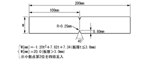
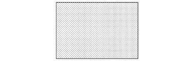
- FIG. 1 It is a figure which shows the shape of the test piece of the notch tensile test. It is a schematic diagram of the hardness distribution in a steel sheet.
- A shows the hardness distribution in the steel of the present invention
- B is the hardness distribution in the comparative steel (an example in which the distances between the hardness peaks are excessively separated).
- Indicates, and C indicates the hardness distribution in the comparative steel (an example in which the difference between the maximum value and the minimum value of hardness is excessively large).
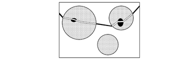
- FIG. 4A it is a schematic view showing how the deformation progressed further and the cracks generated in the coarse cementite in the martensite propagated to the surrounding martensite.
- FIG. 4B it is a schematic view showing how the deformation further progresses and the crack penetrating the martensite propagates to the surrounding ferrite and another martensite in the vicinity.
- the steel sheet according to the embodiment of the present invention (the steel sheet according to the present embodiment) and its manufacturing conditions will be sequentially described.
- the reason for limiting the component composition (chemical composition) of the steel sheet according to the present embodiment will be described.
- % related to the component composition means mass%.
- C 0.050 to 0.180% C is an element that greatly enhances the strength of steel. If the C content is less than 0.050%, sufficient tensile strength (maximum tensile strength) cannot be obtained. Therefore, the C content is set to 0.050% or more. In order to increase the tensile strength, the C content is preferably 0.060% or more, more preferably 0.070% or more. On the other hand, if the C content exceeds 0.180%, a large amount of retained austenite is generated after the heat treatment, and the impact resistance is not sufficiently improved. Therefore, the C content is set to 0.180% or less. In order to further improve the impact resistance, the C content is preferably 0.160% or less, more preferably 0.140% or less.
- Si 0.01 to 1.20% Si is an element that refines iron-based carbides and contributes to improving the balance of strength-formability-impact resistance, but if Si is excessively contained, the steel becomes embrittled.
- the Si content is set to 0.01% or more. Since Si particularly enhances the strength-moldability balance, the Si content is preferably 0.05% or more, and more preferably 0.10% or more.
- the Si content is set to 1.20% or less.
- solid solution Si is an element that promotes the destruction of ferrite. Therefore, when the impact resistance is further enhanced, the Si content is preferably 1.00% or less, more preferably 0.80% or less.
- Mn 0.80 to 3.00%
- Mn is an element that enhances the hardenability of steel and contributes to the improvement of strength. If the Mn content is less than 0.80%, a soft structure is formed in the cooling process of annealing, and it becomes difficult to secure the required strength. Therefore, the Mn content is set to 0.80% or more. It is preferably 1.00% or more, more preferably 1.20% or more. On the other hand, when the Mn content exceeds 3.00%, the macrohomogeneity in the steel sheet is impaired due to the uneven distribution of Mn during casting, and the impact resistance deteriorates. Therefore, the Mn content is set to 3.00% or less. From the viewpoint of ensuring good impact resistance, the Mn content is preferably 2.80% or less, and more preferably 2.60% or less.
- Al 0.005 to 0.600%
- Al is an element that functions as a deoxidizing material. If the Al content is less than 0.005%, the deoxidizing effect cannot be sufficiently obtained. Therefore, the Al content is set to 0.005% or more. It is preferably 0.010% or more, more preferably 0.020% or more.
- Al is also an element that forms a coarse oxide that is the starting point of fracture and embrittles steel. When the Al content exceeds 0.600%, a large number of coarse oxides acting as a starting point of fracture are generated, and the slab is easily cracked. Therefore, the Al content is set to 0.600% or less. In order to improve the balance between moldability and impact resistance, the Al content is preferably 0.450% or less, more preferably 0.300% or less.
- Ti 0.005 to 0.120%
- Ti is an element that has the effect of reducing S, N, and O that form coarse inclusions that act as the starting point of fracture.
- Ti is an element having the effect of refining the structure and enhancing the balance of strength-moldability-impact resistance.
- the Ti content is set to 0.005% or more.
- the Ti content is preferably 0.010% or more.
- the Ti content is 0.120% or less.
- the inclusion of Ti may suppress recrystallization during heating after cold rolling, and unrecrystallized ferrite may remain to deteriorate the moldability. From this point of view, the Ti content is preferably 0.075% or less, and more preferably 0.060% or less.
- P 0.050% or less
- P is an element that embrittles steel and embrittles the molten part generated by spot welding. If the P content exceeds 0.050%, the steel sheet becomes brittle and easily cracks in the production process. Therefore, the P content is set to 0.050% or less. From the viewpoint of productivity, P is preferably 0.035% or less, more preferably 0.020% or less.
- the lower limit of the P content includes 0%, but if the P content is reduced to less than 0.001%, the manufacturing cost increases significantly. Therefore, 0.001% is a practical lower limit on the practical steel sheet.
- S 0.0080% or less
- S is an element that forms Mn sulfide and impairs moldability such as ductility, hole expandability, stretch flangeability, and bendability and impact resistance. If the S content exceeds 0.0080%, the moldability is significantly lowered, so the S content is set to 0.0080% or less. In order to improve the balance between moldability and impact resistance, the S content is preferably 0.0060% or less, more preferably 0.0040% or less.
- the lower limit of the S content includes 0%, but if the S content is reduced to less than 0.0001%, the manufacturing cost increases significantly. Therefore, 0.0001% is a practical lower limit on the practical steel sheet.
- N 0.0125% or less
- N is an element that forms a nitride and inhibits moldability such as ductility, hole expansion property, stretch flange property, and bendability. If the N content exceeds 0.0125%, the moldability deteriorates. Therefore, the N content is set to 0.0125% or less. Further, N is an element that causes welding defects during welding and hinders productivity. Therefore, the N content is preferably 0.0080% or less, more preferably 0.0060% or less.
- the lower limit of the N content includes 0%, but if the N content is reduced to less than 0.0005%, the manufacturing cost increases significantly, so 0.0005% is a practical lower limit on the practical steel sheet.
- O 0.0040% or less
- O is an element that forms an oxide and inhibits moldability such as ductility, hole expansion, stretch flangeability, and bendability.
- the O content is set to 0.0040% or less. It is preferably 0.0030% or less, more preferably 0.0020% or less.
- the lower limit of the O content includes 0%, but if the O content is reduced to less than 0.0001%, the manufacturing cost increases significantly. Therefore, 0.0001% is a practical lower limit on the practical steel sheet.
- Nb 0 to 0.075%
- Nb is an element that contributes to the improvement of steel sheet strength by strengthening with precipitates, strengthening fine granulation by suppressing the growth of ferrite crystal grains, and strengthening dislocations by suppressing recrystallization.
- the lower limit of the Nb content includes 0%, but in order to sufficiently obtain the effect of improving the strength of Nb, the Nb content is preferably 0.005% or more, preferably 0.010%. The above is more preferable.
- the Nb content is set to 0.075% or less. From the viewpoint of moldability, the Nb content is preferably 0.050% or less, more preferably 0.040% or less.
- V 0 to 1.000%
- V is an element that contributes to the improvement of steel sheet strength by strengthening by precipitates, strengthening fine granulation by suppressing the growth of ferrite crystal grains, and strengthening dislocations by suppressing recrystallization. Since V does not necessarily have to be contained, the lower limit of the V content includes 0%, but in order to sufficiently obtain the strength improving effect by the V content, the V content is preferably 0.010% or more, and 0. 030% or more is more preferable. On the other hand, when the V content exceeds 1.000%, a large amount of carbonitride is precipitated and the moldability is lowered. Therefore, the V content is set to 1.000% or less. It is preferably 0.200% or less.
- Cr 0 to 1.50% Cr is an element that enhances hardenability of steel and contributes to improvement of steel sheet strength, and is an element that can replace a part of Mn. Since Cr does not necessarily have to be contained, the lower limit of the Cr content includes 0%, but in order to sufficiently obtain the strength improving effect due to the Cr content, the Cr content is preferably 0.05% or more. 20% or more is more preferable. On the other hand, if the Cr content exceeds 1.50%, there is a concern that coarse Cr carbides that can serve as a starting point of fracture are formed. Therefore, the Cr content is set to 1.50% or less. It is preferably 0.80% or less.
- Ni 0 to 1.50%
- Ni is an element that suppresses phase transformation at high temperatures and contributes to the improvement of steel sheet strength, and is an element that can replace a part of Mn. Since Ni does not necessarily have to be contained, the lower limit of the Ni content includes 0%, but in order to sufficiently obtain the strength improving effect due to the Ni content, the Ni content is preferably 0.05% or more, and 0. 20% or more is more preferable. On the other hand, if the Ni content exceeds 1.50%, the weldability deteriorates. Therefore, the Ni content is set to 1.50% or less. It is preferably 1.00% or less.
- Cu 0 to 1.50%
- Cu is an element that is present in steel as fine particles and contributes to the improvement of steel sheet strength, and is an element that can replace a part of C and / or Mn. Since Cu does not necessarily have to be contained, the lower limit of the Cu content includes 0%, but in order to sufficiently obtain the strength improving effect of Cu, the Cu content is preferably 0.05% or more, preferably 0.15. % Or more is more preferable. On the other hand, if the Cu content exceeds 1.50%, the weldability deteriorates. Therefore, the Cu content is set to 1.50% or less. It is preferably 0.80% or less.
- Mo 0 to 1.00%
- Mo is an element that suppresses phase transformation at high temperatures and contributes to the improvement of steel sheet strength, and is an element that can replace a part of C and / or Mn. Since Mo does not necessarily have to be contained, the lower limit of the Mo content includes 0%, but in order to sufficiently obtain the strength improving effect due to the Mo content, the Mo content is preferably 0.03% or more, and is 0. .06% or more is more preferable. On the other hand, when the Mo content exceeds 1.00%, the hot workability is lowered and the productivity is lowered. Therefore, the Mo content is set to 1.00% or less. It is preferably 0.50% or less, and more preferably 0.30% or less.
- W 0 to 1.000%
- W is an element that suppresses phase transformation at high temperatures and contributes to the improvement of steel sheet strength, and is an element that can replace a part of C and / or Mn. Since W does not necessarily have to be contained, the lower limit of the W content includes 0%, but in order to sufficiently obtain the effect of improving the strength of W, the W content is preferably 0.030% or more, preferably 0.100. % Or more is more preferable. On the other hand, when the W content exceeds 1.000%, the hot workability is lowered and the productivity is lowered. Therefore, the W content is set to 1.000% or less. It is preferably 0.600% or less.
- B 0 to 0.0060%
- B is an element that suppresses phase transformation at high temperatures and contributes to the improvement of steel sheet strength, and is an element that can replace a part of Mn. Since B does not necessarily have to be contained, the lower limit of the B content includes 0%, but in order to sufficiently obtain the strength improving effect due to the B content, the B content is preferably 0.0005% or more, and 0. More preferably, it is 0010% or more. On the other hand, if the B content exceeds 0.0060%, a B precipitate is formed, and the effect of B is rather reduced. Therefore, the B content is set to 0.0060% or less. In order to suppress the formation of B precipitates and effectively obtain the effect of B, the B content is preferably 0.0035% or less.
- Sn 0 to 1.000%
- Sn is an element that suppresses the coarsening of crystal grains and contributes to the improvement of steel sheet strength. Since Sn does not necessarily have to be contained, the lower limit of the Sn content includes 0%, but the Sn content is more preferably 0.010% or more in order to sufficiently obtain the effect of the Sn content. On the other hand, if the Sn content exceeds 1.000%, the steel sheet becomes brittle and may break during rolling, so the Sn content is set to 1.000% or less.
- Sb 0 to 0.200%
- Sb is an element that suppresses the coarsening of crystal grains and contributes to the improvement of steel sheet strength. Since Sb does not necessarily have to be contained, the lower limit of the Sb content includes 0%, but the Sb content is preferably 0.005% or more in order to sufficiently obtain the effect of the Sb content. On the other hand, if the Sb content exceeds 0.200%, the steel sheet becomes brittle and may break during rolling, so the Sb content is set to 0.200% or less.
- composition of the steel sheet according to the present embodiment may contain one or more of Ca, Ce, Mg, Zr, La, and REM, if necessary.
- One or more of Ca, Ce, Mg, Zr, La, REM: 0 to 0.0100% in total Ca, Ce, Mg, Zr, La and REM are elements that contribute to the improvement of moldability.
- the lower limit of the total content of one or more of Ca, Ce, Mg, Zr, La, and REM includes 0%, but in order to sufficiently obtain the effect of improving moldability, the content of these elements should be set. A total of 0.0001% or more is preferable, and 0.0010% or more is more preferable.
- the total content of one or more of Ca, Ce, Mg, Zr, La and REM exceeds 0.0100%, the ductility may decrease. Therefore, the total content of the above elements is 0.0100% or less.
- REM Radar Earth Metal
- the balance excluding the above elements is Fe and impurities. Impurities are elements that are inevitably mixed in from steel raw materials and / or in the steelmaking process.
- Impurities H, Na, Cl, Sc, Co, Zn, Ga, Ge, As, Se, Y, Zr, Tc, Ru, Rh, Pd, Ag, Cd, In, Sn, Sb, Te. , Cs, Ta, Re, Os, Ir, Pt, Au, Pb, Bi, Po. Impurities may contain 0.100% or less in total.
- the steel plate according to the present embodiment has a position ((1/8) t) of 1/8 of the plate thickness t in the plate thickness direction from the surface to a position of 3/8 of the plate thickness t in the plate thickness direction from the surface ((3). / 8) Define the microstructure in the range of t).
- the reason is that the microstructure in the above range centered on the position ((1/4) t) of the plate thickness in the plate thickness direction from the surface is a typical structure of the steel sheet, and the steel sheet has a microstructure. This is because it has a strong correlation with mechanical properties.
- the proportions of the following tissues in the microstructures are all volume fractions.
- Ferrite has a structure excellent in moldability and impact resistance, and the steel sheet according to the present embodiment needs to contain 10% or more of ferrite.
- the volume fraction of ferrite is preferably 17% or more, and more preferably 25% or more.
- ferrite is a structure with low strength, and if the volume fraction of ferrite is excessively increased, it is necessary to excessively increase the strength of the remaining portion in order to obtain sufficient strength of the steel sheet. In this case, the moldability and / or impact resistance is rather impaired. From this point of view, the volume fraction of ferrite is limited to 75% or less.
- the volume fraction of ferrite is preferably 65% or less, and more preferably 50% or less.
- the unrecrystallized ferrite is a ferrite in which strain introduced by cold rolling or the like remains, and has higher strength than ordinary ferrite, but is inferior in ductility and impact resistance. Therefore, in the steel sheet according to the present embodiment, the ratio of unrecrystallized ferrite to ferrite is limited to 25% or less.
- the ratio of unrecrystallized ferrite to ferrite is preferably 20% or less, and more preferably 15% or less. In order to improve the moldability, it is more preferable that unrecrystallized ferrite is not contained.
- Martensite 20-90% Martensite is a structure that enhances strength, and the steel sheet according to this embodiment needs to contain 20% or more in volume fraction.
- the volume fraction of martensite is preferably 30% or more, and more preferably 40% or more.
- the volume fraction of martensite is limited to 90% or less.
- the volume fraction of martensite is preferably 75% or less, and more preferably 65% or less.
- Residual austenite 0-5%
- Residual austenite is a structure that improves the strength-ductility balance of a steel sheet, but on the other hand, it is also a structure that acts as a starting point of fracture and lowers impact resistance. Therefore, the volume fraction of the steel sheet according to the present embodiment is limited to 5% or less.
- the volume fraction of retained austenite is preferably 3% or less, and may not be contained in the microstructure.
- Bainite and bainitic ferrite are structures having a strength-formability balance between ferrite and martensite, and both may or may not be contained in a total volume fraction of 50% or less. ..
- Bainite and bainitic ferrite are structures having a strength-formability balance between ferrite and martensite, and both may or may not be contained in a total volume fraction of 50% or less. ..
- Pearlite 0-5% Pearlite is a structure that impairs the balance between strength and moldability, and its volume fraction is limited to 5% or less. In order to enhance the strength-moldability balance, the volume fraction thereof is preferably 3% or less, and most preferably not contained.
- a method for determining the volume fraction (volume%) of the tissue will be described. From the steel sheet according to the present embodiment, a test piece having a cross section parallel to the rolling direction of the steel sheet and perpendicular to the surface of the steel sheet as an observation surface is collected. After polishing the observation surface of the test piece, nightal etching is performed, and 1 in the region from (1/8) t (t: plate thickness) to (3/8) t (t: plate thickness) from the surface of the plate thickness. With the above field of view, a total area of 2.0 ⁇ 10-9 m 2 or more was observed with a field emission scanning electron microscope (FE-SEM: Field Emission Scanning Electron Microsope), and the structure morphology (crystal grains) was observed.
- FE-SEM Field Emission Scanning Electron Microsope
- Each structure is identified based on its shape, subgrain boundaries in crystal grains, carbon dioxide formation state, etc.), its area fraction (area%) is measured, and this area fraction is used as the volume fraction (volume%).
- volume fraction of ferrite, unrecrystallized ferrite, bainite, bainite ferrite, martensite, and MA (a region consisting of both martensite and retained austenite, or one of them) is obtained.
- the area to be analyzed in each field of view shall be 4.0 ⁇ 10 -10 m 2 or more.
- the volume fraction is analyzed by the point counting method in each field of view, 15 lines are drawn parallel to the rolling direction, and 15 lines are also drawn vertically, and the structure is discriminated at 225 intersections consisting of these lines. ..
- the volume fraction of retained austenite in the microstructure of the steel sheet according to this embodiment is analyzed by an X-ray diffraction method. In the region from (1/8) t (t: plate thickness) to (3/8) t (t: plate thickness) from the surface of the plate thickness of the test piece, the surface parallel to the steel plate surface is finished as a mirror surface, and X The surface integral of FCC iron is analyzed by the linear diffraction method. The area fraction is used as the volume fraction of retained austenite.
- volume fraction of martensite contained in MA can be obtained by subtracting the volume fraction of the obtained retained austenite from the volume fraction of MA obtained by observation.
- the sum of the martensite contained in MA and the volume fraction determined to be martensite by observation with FE-SEM is adopted as the volume fraction of martensite.
- cementite and carbides precipitated alone are not included in the volume fraction.
- Martensite satisfying the formula (1) is a structure having high strength, but it is a brittle structure, and it is necessary to control its internal structure to improve impact resistance. Brittle fracture occurs when plastic deformation is unlikely to occur. Therefore, fine charcoal is generated inside the martensite to locally generate brittle cracks, which are used as the starting point of the plastic deformation, and the plastic deformation of martensite is performed. Efficient induction can suppress the occurrence of brittle fracture in martensite. Cementite is effective as the starting point of plastic deformation.
- martensite contains cementite satisfying the following formula (1).
- the formula (1) is an index of the susceptibility of cracks to coarse cementite that easily causes brittle cracks inside martensite.
- Equation (1) is an equation for calculating the cementite particles in the observed martensite, which have a large effect on impact resistance and are the fifth cementite particles counting from the one having the largest circle-equivalent diameter.
- d i denotes the particle diameter [[mu] m] i th circularly equivalent diameter in a large cementite particles
- a i-equivalent diameter i th circularly indicates an aspect ratio in a large cementite particles.
- the value on the middle side of the equation (1) is set to 1.00 or more and 10.00 or less.
- the value of the middle side of the formula (1) is preferably 2.00 or more and 9.00 or less.
- the equivalent circle diameter and aspect ratio of cementite particles are measured by the following methods. That is, in the region of (1/8) t to (3/8) t from the surface of the plate thickness of the test piece on the same observation surface as the measurement of the area fraction of each structure described above, the magnification is 3000 times by FE-SEM.
- the minor axis and the major axis are measured for 10 or more cementites in any martensite.
- the value obtained by taking the square root from the product of the major axis and the minor axis of the cementite particles is defined as the equivalent circle diameter, and the value obtained by dividing the major axis of the cementite particles by the minor axis is defined as the aspect ratio.
- the density of transition carbides contained in martensite is 1.0 ⁇ 10 13 pieces / m 3 or more
- cementite is introduced into the martensite in order to propagate the plastic deformation while suppressing the formation of voids.
- Other iron-based transition carbides ⁇ -carbide, ⁇ -carbide, ⁇ -carbide
- These carbides have good consistency with the surrounding bcc iron, and voids are unlikely to occur in the surrounding area, but their physical properties are different from those of the surrounding bcc iron, and plastic deformation is likely to occur in the surrounding area.
- the martensite in the steel sheet according to the present embodiment needs to have 1.0 ⁇ 10 13 pieces / m 3 or more of transition carbides.
- martensite contains 1.0 ⁇ 10 13 / m 2 or more dislocations (mainly movable dislocations).
- the dislocation density is more preferably 3.0 ⁇ 10 13 / m 2 or more.
- Observation of cementite, transition carbides, and rearrangements in martensite is performed using a transmission electron microscope (TEM: Transmission Electron Microscope).
- TEM Transmission Electron Microscope
- the density of transition carbides and movable dislocations the number of carbides or the length of dislocations is measured in an area of 5.0 ⁇ 10-12 m 2 or more in each of the five or more different visual fields, and further, EELS (Electron).
- EELS Electron
- Average grain size of old austenite grains 5.0 ⁇ m or less
- matrix austenite grains generated by martensite when it becomes a steel plate, it is observed as old austenite grains. It is effective to make it finer.
- the average particle size of the matrix austenite grains (former austenite grains) is preferably 5.0 ⁇ m or less, and more preferably 3.5 ⁇ m or less.
- the matrix austenite grains are isotropic, and the average aspect ratio of the matrix austenite grains (former austenite grains) is preferably 2.50 or less. It is more preferably 75 or less.
- 10 or more matrix austenite grains (former austenite grains) were randomly selected from the microstructure in the field of measurement of the body integration rate by the FE-SEM described above.
- Density of coarse inclusions with a circle-equivalent diameter of 10 ⁇ m or more (number density): 0.50 pieces / mm 2 or less
- Coarse inclusions with a circle-equivalent diameter of 10 ⁇ m or more act strongly as a starting point for brittle fracture and improve the impact resistance of steel sheets. It will be a big loss. Therefore, the number density of the coarse inclusions as described above is limited to 0.50 pieces / mm 2 or less. The lower the number density of the coarse inclusions, the more preferable, and it is preferably 0.33 pieces / mm 2 or less.
- the number density of the coarse inclusions is 10 ⁇ m or more in the circle equivalent diameter in the range of 50 mm 2 or more in total in the total thickness of the steel plate by observing the mirror-polished observation surface on the observation surface of the microstructure described above with an optical microscope. It is obtained by measuring the number density of inclusions in.
- the ratio of the maximum Vickers hardness Hv max to the minimum Vickers hardness Hv min is 1.40 or less and 1.40 or less on a surface parallel to the surface at a position 1/4 of the plate thickness in the plate thickness direction from the surface. ,
- the average value of the minimum distances between the peaks of Vickers hardness (between peaks) is 1.00 mm or less.
- the steel plate according to this embodiment is a steel plate in order to improve impact resistance. Increases internal macro-homogeneity.
- the ratio of the maximum value Hv max and the minimum value Hv min of the Vickers hardness measurement value (HV max / HV) on a surface parallel to the surface at a position 1/4 of the plate thickness in the plate thickness direction from the surface. min ) is 1.40 or less.
- the average distance between the Vickers hardness peaks is set to 1. It shall be 0.00 mm or less. The smaller the average distance between the peaks is, the more preferable it is, preferably 0.85 mm or less, and more preferably 0.70 mm or less.
- the Vickers hardness is measured by measuring the diagonal length of the indentation with respect to the mirror-polished surface in the region near 1/4 thickness ((1/4) t) in the plate thickness direction parallel to the surface of the steel plate. It is measured by a load (100 to 300 gf) having a size of 25 ⁇ m or more and 45 ⁇ m or less. Indentations are given at a pitch of 100 ⁇ m, and indentations of 20 points in the rolling direction and 30 points in the plate width direction, for a total of 600 points, are given in a grid pattern.
- the maximum and minimum values of the hardness shall be the maximum hardness and the minimum hardness in the measurement results of 600 points.
- the hardness peak of the 600 measurement points, 504 points excluding the 96 points on the outermost circumference are compared with the hardness measurement values of the four points adjacent to each measurement point. Then, the point where the hardness at the measurement point is maximum (the point where the hardness is larger than the adjacent four points) is determined as the peak.
- the average distance between peaks is determined by mapping the peaks, measuring the distance from the nearest peak at each peak, and using the average value as the average distance between peaks.
- the steel sheet according to the present embodiment may be a steel sheet having a zinc plating layer or a zinc alloy plating layer on one side or both sides of the steel sheet, or an alloyed plating layer obtained by alloying the zinc plating layer or the zinc alloy plating layer. It may be a steel plate having.
- the plating layer formed on one side or both sides of the steel sheet according to the present embodiment is preferably a zinc plating layer or a zinc alloy plating layer containing zinc as a main component.
- the zinc alloy plating layer preferably contains Ni as an alloy component.
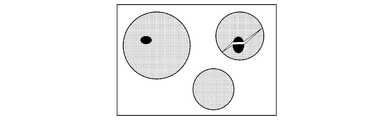
- the macroscopic hardness distribution (for example, as shown in FIG. 2A) is controlled with respect to the fracture progress behavior following FIG. 4A ⁇ FIG. 4B ⁇ FIG. 4C.
- FIG. 4A by suppressing local strain and stress concentration on the inhomogeneous microstructure with cementite that is the origin of fracture as shown in FIG. 3A, and by controlling the size and shape of cementite. Suppress the occurrence of severe destruction.
- FIGS. 4B and 4C is suppressed by increasing the toughness of martensite. As a result, moldability and impact resistance are improved.
- the zinc plating layer and the zinc alloy plating layer are formed by a hot-dip plating method, an electroplating method, or a thin-film deposition plating method.
- the Al content of the galvanized layer increases, the adhesion between the steel sheet surface and the galvanized layer decreases. Therefore, the Al content of the galvanized layer is preferably 0.5% by mass or less.
- the Fe amount of the hot-dip galvanized layer is preferably 3.0% by mass or less in order to improve the adhesion between the steel sheet surface and the galvanized layer.
- the galvanized layer is an electrogalvanized layer
- the Fe amount of the plated layer is preferably 0.5% by mass or less in terms of improving corrosion resistance.
- the zinc plating layer and the zinc alloy plating layer include Ag, B, Be, Bi, Ca, Cd, Co, Cr, Cs, Cu, Ge, Hf, Zr, I, K, La, Li, Mg, Mn, Mo, Contains one or more of Na, Nb, Ni, Pb, Rb, Sb, Si, Sn, Sr, Ta, Ti, V, W, Zr, and REM within a range that does not impair corrosion resistance and moldability. You may. In particular, Ni, Al, and Mg are effective in improving corrosion resistance.
- the zinc plating layer or the zinc alloy plating layer on the surface of the steel sheet according to the present embodiment may be an alloyed plating layer that has been alloyed.
- the amount of Fe in the hot-dip galvanizing layer or the hot-dip galvanizing alloy plating layer is set to 7. It is preferably 0 to 13.0% by mass.
- the thickness of the steel sheet according to the present embodiment is not limited to a specific range, but is preferably 0.4 to 5.0 mm in consideration of versatility and manufacturability. If the plate thickness is less than 0.4 mm, it becomes difficult to maintain the steel plate shape flat, and the dimensional and shape accuracy deteriorates. Therefore, the plate thickness is preferably 0.4 mm or more. More preferably, it is 0.6 mm or more. On the other hand, if the plate thickness exceeds 5.0 mm, it becomes difficult to apply appropriate strain and control the temperature in the manufacturing process, and a homogeneous structure may not be obtained. Therefore, the plate thickness is preferably 5.0 mm or less. More preferably, it is 4.5 mm or less.
- the steel sheet according to the present embodiment can obtain the effect if it has the above characteristics regardless of the manufacturing method, but it is preferable because it can be stably manufactured by the manufacturing method including the following steps.
- (I) A molten steel having a predetermined chemical composition is cast so that the average cooling rate in the range of 700 to 550 ° C. at the surface temperature is 10 ° C./hour to 75 ° C./hour, and the thickness is 100 to 500 mm or less. Casting process to obtain slabs,
- (III) A cooling step of cooling the hot-rolled steel sheet to room temperature.
- (IV) A cold rolling step of cold-rolling the hot-rolled steel sheet at a total reduction ratio of 30 to 90% and a rolling completion temperature of 250 ° C. or lower to obtain a cold-rolled steel sheet.
- (V) An annealing step in which the cold-rolled steel sheet is heated to an annealing temperature of 760 ° C. or higher and Ac3 + 20 ° C. or lower and cooled to 80 ° C. or lower.
- annealing temperature of 760 ° C. or higher and Ac3 + 20 ° C. or lower and cooled to 80 ° C. or lower.
- a slab having the same composition as the chemical component (component composition) of the steel sheet according to the present embodiment described above is cast.
- the slabs to be subjected to hot rolling are preferably produced by continuous casting from the viewpoint of manufacturing cost, but may be produced by other casting methods (for example, ingot forming method).
- the thickness of the slab is preferably 100 mm or more and 500 mm or less, and preferably 150 mm or more and 350 mm or less in order to give an appropriate amount of strain in the hot rolling process. If the thickness of the slab is less than 100 mm, the steel sheet after applying an appropriate amount of strain becomes too thin, and it is difficult to obtain a flat shape.
- the average cooling rate from when the surface temperature reaches 700 ° C. to when it reaches 550 ° C. is 10 ° C./hour to 75 ° C./hour.
- the average cooling rate is less than 10 ° C./hour, segregation will proceed excessively and the maximum hardness of the finally obtained steel sheet will be increased.
- the ratio to the minimum hardness becomes large, and the impact resistance deteriorates.
- the average cooling rate in the temperature range is preferably 10 ° C./hour or higher, and more preferably 13 ° C./hour or higher.
- the average cooling rate from when the surface temperature reaches 700 ° C to when it reaches 550 ° C exceeds 75 ° C / hour, segregation does not proceed sufficiently, and the concentration fluctuation with a large period causes the strength fluctuation of the steel sheet. The effect is increased, the average distance between the hardness peaks of the finally obtained steel sheet is increased, and the impact resistance is deteriorated.
- the average cooling rate is preferably 75 ° C./hour or less, more preferably 65 ° C./hour or less, and even more preferably 30 ° C./hour or less.
- the slab may be further cooled and once cooled to room temperature, but since the energy required for heating can be reduced, the slab may be directly subjected to hot rolling at a high temperature.
- the slab is hot-rolled.
- the slab is heated to a temperature of 1200 ° C. or higher.
- the heating temperature of the slab is low, a local elemental enrichment site is generated due to the coarse carbonitride in the slab, and the ratio of the maximum hardness to the minimum hardness of the finally obtained steel sheet becomes large.
- the heating temperature of the slab is preferably 1220 ° C. or higher.
- the heating temperature of the slab exceeds 1350 ° C., the structure becomes coarse and the effect of homogenizing the inside of the steel sheet by the subsequent hot rolling is impaired. Therefore, the heating temperature of the slab is preferably 1350 ° C. or lower, preferably 1320 ° C. or lower.
- hot rolling is performed.
- the total reduction rate is preferably 70% or more.
- the upper limit of the total reduction rate in the temperature range of 1050 ° C. or higher is not particularly set, but the total reduction rate is preferably 95% or less because excessive reduction impairs the shape of the steel sheet.
- Equation (2) consists of an equation expressing the degree of strain accumulation due to rolling and the degree of recrystallization of austenite. The larger the value on the left side of equation (2), the more the austenite grain boundaries move inside the steel sheet, and the steel sheet Internal homogenization progresses.
- the former (term containing the constant A 2 ) is derived from the strain accumulation degree
- the latter (term containing the constant A 3 ) is derived from the formula expressing the degree of recrystallization of austenite.
- the other terms are obtained by rearranging the coefficients of the two equations.
- n is the number of times of rolling from the maximum heating temperature to the temperature of the steel sheet reaching 1050 ° C.
- h i denotes the thickness of the steel sheet obtained by performing an i-th rolling [mm].
- h 0 is the thickness of the heated slab.
- t i is the elapsed time [seconds] from the i-th rolling to the i + 1th rolling.
- t n is the elapsed time from the nth rolling to the steel sheet temperature reaching 1050 ° C.
- Hot rolling is performed in a temperature range of 1050 ° C. or higher under the condition that the value on the left side of the formula (2) is 1.00 or higher.
- the upper limit of the value on the left side of the formula (2) is not particularly set, but if the value on the left side of the formula (2) becomes excessively large, the structure of the steel sheet becomes coarse and the structure becomes finer by hot rolling after reaching 1050 ° C. It is preferable to limit the value on the left side of the equation (2) to 6.00 or less because it becomes difficult. Since equipment such as a heating device is required to increase the value on the left side of the formula (2), the value on the left side of the formula (2) is preferably 4.00 or less from the viewpoint of production cost.
- the hot rolling conditions from reaching 1050 ° C to the rolling completion temperature shall satisfy the following formula (3).
- Equation (3) is an index representing the micronization behavior of the structure by hot rolling in a temperature range of less than 1050 ° C., and includes a term related to recrystallization nucleation associated with hot rolling and a term related to grain growth after rolling. It is derived and obtained by organizing the coefficients. The symbols in the equation (3) will be described. n is the total number of hot rolling at 1050 ° C. or higher. m is the total number of hot rollings below 1050 ° C. j indicates the number of times of rolling at a temperature lower than 1050 ° C. for rolling performed at a temperature lower than 1050 ° C.
- T'n + m is the average temperature between the rolling temperature and 800 ° C. in the m-th hot rolling at less than 1050 ° C.
- t n + m is the elapsed time from the completion of the m-th hot rolling at less than 1050 ° C. to the temperature of the steel sheet reaching 800 ° C.
- E 2 represents the value on the left side of the equation (2).
- [Element symbol] ([Nb], [Ti], [N], [B], [Mo], [C]) represents the content [mass%] of each element.
- a 4, A 5, A 6 , A 7, A 8 are constants, respectively, 5.86 ⁇ 10 0, 5.00 ⁇ 10 -1, 3.37 ⁇ 10 4, 6.44 ⁇ 10 4, It is 1.35 ⁇ 10 4 .
- R n is first calculated based on the result of the formula (2), R n + 1 is calculated for the first rolling for hot rolling at less than 1050 ° C., then R n + 2 is calculated, and then sequentially. For R n + m (R m + n ) obtained by performing the calculation, it is determined whether the equation (3) is satisfied.
- the value on the left side of the formula (3) is larger than 10.00, the structure after hot rolling becomes coarse, carbon is unevenly distributed along with the phase transformation after hot rolling, and coarse cementite is generated, and finally.
- the desired structure cannot be obtained in the obtained steel sheet.
- the reduction at less than 1050 ° C. is preferably performed under the condition that the value on the left side of the formula (3) is 7.50 or less. It is more preferable to apply under the condition of 0.00 or less.
- the lower limit of the value on the left side of the formula (3) is not particularly set, but it is necessary to make the steel sheet excessively thin in order to make it less than 0.50, and the shape of the steel sheet after hot rolling collapses.
- the completion temperature of hot rolling may be selected within the range satisfying the formula (3), but if it is less than 800 ° C., the rolling reaction force becomes large and there is a concern that the shape of the steel sheet deteriorates. Therefore, the temperature is preferably 800 ° C. or higher. Further, in order to satisfy the equation (3) with the rolling completion temperature exceeding 1000 ° C., the steel sheet needs to be reheated, which increases the production cost. Therefore, the rolling completion temperature is preferably 1000 ° C. or lower.
- the average cooling rate from the completion temperature of hot rolling to 630 ° C is 20 ° C / sec or more, and in the temperature range of 630 to 500 ° C, 100 ° C or less so as to satisfy the formula (4) ( For example, cool to room temperature).
- the average cooling rate from the completion temperature of hot rolling to 630 ° C is less than 20 ° C / sec, carbon is unevenly distributed along with the phase transformation after hot rolling to generate coarse cementite, which is finally obtained.
- the desired structure cannot be obtained in the steel sheet to be obtained.
- the macro-homogeneity of the steel sheet is also impaired by the phase transformation in this temperature range.
- the average cooling rate from the completion temperature of hot rolling to 630 ° C. is preferably 30 ° C./sec or more.
- the upper limit of the average cooling rate is not particularly set, but since a special refrigerant is required to obtain a cooling rate exceeding 200 ° C./sec, the average cooling rate is preferably 200 ° C./sec or less from the viewpoint of production cost. ..
- the average cooling rate and the average heating rate are values obtained by dividing the temperature difference between the start point and the end point of the set range by the elapsed time from the start point to the end point.
- P 13 is an index representing the degree of progress of the precipitation of cementite and Nb, carbonitride Ti in the temperature range from 630 ° C. obtained by calculating using the equation below to 500 ° C..
- the temperature range from 630 ° C to 500 ° C is divided into 13 every 10 ° C, and the 1st to 13th phase transformations and the degree of precipitation are calculated.
- P 1 is an index for evaluating the degree of precipitation progress in the temperature range of 630 ° C. to 620 ° C.
- item X 1 for evaluating the degree of progress of phase transformation
- item Y i for evaluating the degree of precipitation in the region after transformation. Consists of. The larger X 1 is, the more the phase transformation proceeds, and the larger Y 1 is, the more the precipitation of Nb and Ti carbides (alloy carbides) in the post-transformation region progresses.
- the symbols in the equation will be described.
- a 9 , A 10 , A 11 , A 12 , A 13 , A 14 , A 15 , A 16 , and A 17 are constants, and 3.70 ⁇ 10 12 , 3.93 ⁇ 10 4 , 1.93 ⁇ , respectively. 10 0, 1.00 ⁇ 10 7, 9.09 ⁇ 10 -2, 2.80 ⁇ 10 -3, 2.54 ⁇ 10 4, 4.12 ⁇ 10 -2, which is 3.03 ⁇ 10 4.
- [Element symbol] [C], [Mn], [Si], [Cr], [Ni], [Al], [Nb], [B], [Mo], [Ti], [N]) is The content of each element [mass%].
- E 3 is the value on the left side of the above equation (3).
- P 13 in the above formula (4) is less than 1.00 ⁇ 10-8 , some Ti and Nb remain in solid solution, recrystallization after cold rolling is suppressed, and unrecrystallized. Ferrite remains.
- P 13 is set to 1.00 ⁇ 10-8 or more.
- P 13 is preferably set to 2.00 ⁇ 10 -8 or more.
- P 13 is limited to 1.00 ⁇ 10-7 or less.
- P 13 is preferably set to 7.50 ⁇ 10 -8 or less, and more preferably set to 6.00 ⁇ 10 -8 or less.
- the temperature of the steel sheet may be lowered to 500 ° C. and then reheated to 500 ° C. or higher.
- the total rolling reduction in cold rolling shall be 30% or more and 90% or less. If the total reduction ratio in cold rolling is less than 30%, the progress of recrystallization in the subsequent heat treatment becomes insufficient, and unrecrystallized ferrite remains. Further, from the viewpoint of refining the structure and enhancing the balance of strength-moldability-impact resistance, the total reduction rate is preferably 40% or more, and more preferably 50% or more. On the other hand, when the total rolling reduction in cold rolling exceeds 90%, the anisotropy of the steel sheet increases and the formability deteriorates.
- the total reduction ratio is preferably 80% or less, more preferably 70% or less, in order to reduce the anisotropy of the steel sheet.
- cold rolling the temperature of the steel sheet rises due to heat generated by processing. If the temperature of the steel sheet rises excessively, the accumulation of processing strain does not proceed sufficiently, and the progress of recrystallization may be hindered. Therefore, the rolling reduction and the inter-pass time are controlled so that the temperature of the steel sheet (cold rolling completion temperature) at the time of completion of cold rolling is 250 ° C. or lower.
- the completion temperature of cold rolling is preferably 200 ° C. or lower in order to promote recrystallization efficiently.
- the steel sheet (cold-rolled steel sheet) after cold rolling is heat-treated (annealed).
- the heating rate is controlled and recrystallization proceeds. If the average heating rate from 400 ° C. to 550 ° C. is less than 3.0 ° C./sec, the recovery of dislocations in the steel sheet proceeds excessively and recrystallization is suppressed, so that the average in the temperature range of 400 to 550 ° C.
- the heating rate shall be 3.0 ° C./sec or higher.
- the upper limit of the average heating rate is not particularly set, it is preferably 200 ° C./sec or less from the viewpoint of production cost. Subsequently, in heating from 550 ° C. to Ac1 (° C.), heating is performed so that the temperature history satisfies the formula (5).
- the middle side of the formula (5) is a formula expressing the degree of recrystallization progress, and the temperature range from 550 ° C to Ac1 (° C) is divided into 10 equal parts, and the degree of recrystallization in the residence time in each temperature range It is the sum that evaluated whether it can progress.
- the symbols in the equation will be described.
- a 18, A 19, A 20 is any constants, respectively, 1.54 ⁇ 10 16, 3.81 ⁇ 10 4, a 3.68 ⁇ 10 2.
- r represents the rolling reduction in cold rolling.
- Ac1 is an Ac1 point (° C.) obtained for each steel by the method described later.
- E 4 is the value of P 13 in the above equation (4).
- [Element symbol] ([Nb], [Ti], [N]) indicates the content [mass%] of each element.
- t i represents the residence time [s] in the i-th temperature range counting from 550 ° C.. If the value at the middle side of the formula (5) is less than 1.00, recrystallization does not proceed sufficiently and the moldability deteriorates. Therefore, the value at the middle side of the equation (5) is set to 1.00 or more. In order to sufficiently proceed with recrystallization for the purpose of improving moldability, the value at the middle side of the formula (5) is preferably 1.25 or more, and more preferably 1.50 or more. On the other hand, in the temperature range from 550 ° C. to Ac1, the declining growth of cementite progresses.
- the upper limit of the middle side of the formula (5) is set to 10.00.
- the value at the middle side of the formula (5) is preferably 7.00 or less, and more preferably 5.00 or less.
- the average heating rate from Ac1 (° C.) to Ac1 + 20 (° C.) is set to 1.0 ° C./sec or more.
- the average heating rate in the temperature range from Ac1 to Ac1 + 20 ° C. is preferably 3.0 ° C./sec or higher, and more preferably 5.0 ° C./sec or higher.
- the average heating rate in the temperature range of Ac1 to Ac1 + 20 ° C. is high, cementite tends to remain undissolved and the impact resistance deteriorates.
- the average heating rate is preferably 50 ° C./sec or less, preferably 30 ° C./sec or less, and more preferably 15 ° C./sec or less.
- the heating rate from Ac1 + 20 ° C. to the maximum heating temperature is not particularly specified, but is preferably 5.0 ° C./sec or less in order to grow austenite isotropically.
- the maximum heating temperature (annealing temperature) in the heat treatment is 760 ° C. or higher. If the annealing temperature is less than 760 ° C., coarse cementite remains undissolved and the impact resistance deteriorates.
- the annealing temperature is preferably 770 ° C. or higher, more preferably 780 ° C. or higher so that austenite is sufficiently produced at the annealing temperature. ..
- the annealing temperature is set to Ac3 + 20 ° C. or lower.
- the annealing temperature is preferably Ac3 (° C.) or lower, and more preferably Ac3-20 ° C. or lower.
- the Ac1 point and the Ac3 point are obtained by cutting out a small piece from the steel plate after cold rolling, heating it to 1200 ° C. at 3 ° C./sec, and measuring the volume expansion behavior during that period. For steel sheets after cold rolling that have been manufactured under the same conditions and evaluated at Ac1 and Ac3 points, this measurement is omitted, and there is no problem in determining the manufacturing conditions using the past measurement results.
- the holding time is more preferably 10.0 seconds or more, and further preferably 25.0 seconds or more.
- the upper limit of the holding time is not particularly set, it is preferably 200 seconds or less in consideration of the production cost because the macro-homogeneity of the steel sheet does not increase further even if it is held for more than 200 seconds.
- the average cooling rate in the temperature range of 720 to 550 ° C. is 10 ° C./sec or more, and in the temperature range of 550 to (Ms-80) ° C., the formula (6) is satisfied, and Ms to (Ms-25).
- the average cooling rate in the temperature range of ° C. is 10 ° C./sec or more, and cooling is performed in the temperature range of Ms to 80 ° C. so as to satisfy the formula (7).
- the average cooling rate between 720 ° C and 550 ° C shall be 10 ° C / sec or more. If the cooling rate in this temperature range is insufficient, pearlite may be generated and a sufficient amount of martensite may not be obtained.
- the upper limit of the cooling rate is not specified, but it is limited to 200 ° C / sec or less from the viewpoint of production cost because a special refrigerant and / or a cooling device is required to achieve a cooling rate exceeding 200 ° C / sec. It is preferable to do so.
- Equation (6) starts at the time when the steel sheet temperature reaches 550 ° C, ends at the time when the martensitic transformation start temperature (Ms) -80 ° C, and sets the temperature history during that period to 10 mag with respect to the elapsed time. Divide and calculate in each time range.
- the bainite transformation start temperature (Bs) [° C.] and the martensitic transformation start temperature (Ms) [° C.] are calculated using the following formulas.
- [Element symbol] ([C], [Mn], [Si], [Cr], [Ni], [Al]) indicates the content [mass%] of each element.
- Ac1 and Ac3 indicate the transformation start temperature [° C.] and the transformation completion temperature [° C.] when each steel sheet is heated to the austenite single phase, respectively.
- TH [° C.] indicates the maximum heating temperature in the heat treatment of each steel sheet. If T H is higher than Ac3, and (Ac3-Ac1) / (T H -Ac1) section 1.00.
- Equation (6) is an equation expressing the behavior of bainite transformation and the accompanying formation of fine cementite.
- C i is an index showing the degree of progress of bainite transformation in the i-th time range from the start of calculation.
- a 21, A 22 are constants, respectively 3.95 ⁇ 10 0, is 7.15 ⁇ 10 3.
- Bs is the bainite transformation start temperature [° C.].
- Ti is the average temperature [° C.] in the time range.
- [Element symbol] ([C], [Si]) indicates the content [mass%] of each component.
- t i is the elapsed time [s] in the range each time. If T i is greater than Bs, and (Bs-T i) section 0. Further, C 0 is set to 0.
- D i is the i-th time range calculation start is an index representing the generated ease of cementite due to bainitic transformation.
- a 23, A 24 are constants, respectively, 4.03 ⁇ 10 -12, a 3.40 ⁇ 10 -1.
- Ti is the average temperature [° C.] in the time range.
- [Element symbol] indicates the content [mass%] of each component.
- t i is the elapsed time [s] in the range each time.
- Middle part of the formula (6) is the sum of the products of C i and D i, if the value of the middle part of equation (6) is below -2.00, excessive solid solution of carbon in the untransformed austenite accumulation However, even if it is cooled to room temperature, the transformation is not completed, a structure containing a large amount of retained austenite is formed, and the impact resistance is deteriorated. On the other hand, when the value at the middle side of the formula (6) exceeds 2.00, cementite is excessively generated and bainite transformation from untransformed austenite proceeds excessively, so that a sufficient amount of martensite cannot be obtained. The strength decreases. From the above viewpoint, it is assumed that the temperature history in the temperature range satisfies the equation (6).
- the value of the middle side of the formula (6) is preferably -1.30 or more and 1.30 or less, and more preferably ⁇ 0.80 or more and 0.80 or less.
- the steel sheet may be subjected to hot-dip galvanizing treatment or hot-dip galvanizing treatment during the temperature history range satisfying the formula (6). At this time, the steel sheet may be reheated before being immersed in the plating bath. Further, as long as the temperature history is within the range satisfying the formula (6), the steel sheet after the plating treatment may be further heated and the plating layer may be alloyed.
- the average cooling rate is set to 10 ° C / sec or more, especially in the section from Ms to (Ms-25) ° C. If the cooling rate during this period is insufficient, the cementite produced from martensite becomes coarse and the number becomes insufficient, and the formula (1) is not satisfied.
- the average cooling rate in the temperature range of Ms to (Ms-25) ° C. is 10 ° C./sec or more, fine cementite is likely to occur.
- the average cooling rate in the temperature range of Ms to (Ms-25) ° C. is preferably 20 ° C./sec or more.
- the average cooling rate is preferably 150 ° C./sec or less, more preferably 75 ° C./sec or less, and even more preferably 50 ° C./sec or less.
- the cooling is performed so that the temperature history in cooling from Ms ° C to 80 ° C satisfies the formula (7).
- Equation (7) is an equation expressing the degree of formation of transition carbides, and the elapsed time from the arrival of the martensitic transformation start temperature (Ms [° C.]) to 80 ° C. is divided into 10 equal parts, and calculations are performed in each time range. , Find the sum.
- E 6 is the value on the middle side of equation (6). If the calculation result of (1-exp [-E 6- A 25 ]) is negative, the value in () is regarded as 0 and calculated.
- a 25 , A 26 , A 27 , A 28 , A 29 , A 30 , A 31 , and A 32 are constant terms, which are 2.31 ⁇ 10 0 , 3.70 ⁇ 10-2 , and 1.44 ⁇ , respectively.
- Ms is the martensitic transformation start temperature obtained by the above method.
- Ti is the average temperature in the i-th time range.
- [Element symbol] ([Mn], [Cr], [Ni], [Si], [Al]) indicates the content [mass%] of each element.
- dt indicates the time [seconds] obtained by dividing the elapsed time from reaching the martensitic transformation start temperature (Ms) to 80 ° C. into 10 equal parts.
- the cooling is performed so that the value at the middle side of the equation (7) is 0.00 or more. It is preferably 0.20 or more, more preferably 0.40 or more.
- the value of the middle side of the formula (7) exceeds 3.00, cementite is generated from a part of the transition carbide, the transition carbide decreases, and a sufficient transition carbide cannot be obtained.
- the value at the middle side of the formula (7) is preferably 2.50 or less, and more preferably 2.20 or less.
- temper rolling with a reduction ratio of 3.00% or less may be performed.
- movable dislocations are introduced inside the martensite, and its plastic deformation is promoted.
- the rolling reduction of the temper rolling is more than 3.00%, the amount of plastic deformation becomes excessive and the uniform elongation is greatly deteriorated, which is not preferable.
- the steel sheet after the heat treatment may be electroplated to form an electroplated steel sheet having a galvanized layer on one or both sides of the steel sheet.
- the steel sheet after the heat treatment may be subjected to a vapor deposition plating treatment to obtain a galvanized steel sheet having a galvanized layer on one side or both sides of the steel sheet.
- the surface of the steel sheet may be modified by controlling the atmosphere during the heat treatment. For example, by heat-treating in a decarburized atmosphere, a steel sheet having an appropriately decarburized surface layer portion of the steel sheet and having excellent bendability can be obtained.
- the conditions in the examples are one condition example adopted for confirming the feasibility and effect of the present invention.
- the present invention is not limited to this one-condition example.
- the present invention may adopt various conditions as long as the gist of the present invention is not deviated and the object of the present invention is achieved.
- the molten steel having the chemical composition shown in Tables 1A and 1B is cast to produce slabs.
- the slab is cooled under the conditions shown in Tables 2A to 2D, and further hot-rolled and cold-rolled under the conditions shown in Tables 2A to 2D to obtain a steel sheet.
- the steel sheet is heat-treated under the conditions shown in Tables 3A to 3D.
- the rest of Tables 1A and 1B are Fe and impurities.
- cooling rate 1 indicates the average cooling rate when the temperature of the slab surface is 700 to 550 ° C. in the slab cooling process.
- “Cooling rate 2” in the hot rolling step indicates the average cooling rate from the completion of hot rolling to 630 ° C.
- heating rate 1 indicates the average heating rate at 400 to 550 ° C.
- Heating rate 2 indicates the average heating rate at Ac1 to (Ac1 + 20) ° C.
- Cooling rate 3 indicates the average cooling rate at 720 to 550 ° C.
- Cooling rate 4 indicates the average cooling rate at Ms to (Ms-25) ° C.
- the "plating bath” in Tables 3A to 3D represents the plating type.
- "EG” is an example of galvanizing a cooled steel sheet by electroplating.
- Thin-film deposition is an example in which zinc plating is applied to a cooled steel sheet by a vapor deposition plating process.
- “GA” is an example in which a steel sheet in the cooling process is immersed in a hot-dip zinc bath in which the effective Al amount [mass%] is controlled to 0.150% or less to apply hot-dip galvanizing.
- GI is an example in which a steel sheet in the cooling process is immersed in a hot-dip zinc bath in which the effective Al amount is controlled to exceed 0.150% to apply hot-dip galvanizing.
- Zn alloy is an example in which a steel sheet in the cooling process is immersed in a hot-dip Zn—Al—Mg bath to apply hot-dip zinc alloy plating.
- the temperature reached by reheating is described as the "alloying temperature”.
- the effective Al amount is a value obtained by subtracting the total Fe amount from the total Al amount in the bath.
- Tables 4A to 4D show the observation results of the microstructure of the steel sheet obtained under the manufacturing conditions of Tables 1A to 3D.
- the microstructure fractions are ferrite ( ⁇ ), unrecrystallized ferrite (unrecrystallized ⁇ ), bainite (B), bainite ferrite (BF), pearlite (P), martensite (M), retained austenite (residual ⁇ ). ), Represents the volume fraction of each tissue.
- "unrecrystallized ferrite” indicates the ratio of unrecrystallized ferrite to ferrite.
- the "surface” represents the state of the surface of the steel sheet, and has an unplated steel sheet (CR), a steel sheet having an electroplating layer (EG), a steel sheet having a hot dip galvanizing layer (GI), and an alloyed hot dip galvanizing layer. It is classified into a steel sheet (GA) and a steel sheet (Zn alloy) having a Zn—Al—Mg alloy plating layer.
- Tables 5A to 5D show the characteristics of the steel sheets obtained under the manufacturing conditions of Tables 1A to 3D.
- the tensile test is carried out in accordance with JIS Z 2241 (2011) by preparing the No. 5 test piece described in JIS Z 2241 (2011) and setting the tensile axis in the width direction of the steel sheet.
- TS Uniform Stress
- UEL Uniform Elongation
- the notch tensile test is performed using the test piece shown in FIG. 1 and a strip-shaped small piece cut out with a length of 200 mm in the width direction of the steel plate, with the width direction of the steel plate as the tensile axis.
- the maximum nominal stress in the notch tensile test is divided by the maximum nominal stress in the tensile test using the No. 5 test piece, and if the value is 0.75 or more, the test is passed.
- the maximum bending angle is measured by a bending test based on VDA-238-100.
- the bending test is performed so that the bending ridge line is parallel to the rolling direction of the steel sheet.
- the bending test is performed by cutting out a test piece cut out from the steel sheets shown in Tables 1A to 4D, and further, by applying a uniaxial tensile strain of 3.0% as a prestrain to the steel sheet with the width direction of the steel sheet as the tensile axis. Perform with a test piece.
- the limit bending angle the bending angle at which the pushing load is maximized (hereinafter referred to as the limit bending angle) satisfies the following equation (9), and the value obtained by dividing the latter limit bending angle by the former limit bending angle is 0. If it is 75 or more, it is passed.
- the symbols in the formula (9) represent t: steel plate thickness [mm] and ⁇ : limit bending angle [degree] of the prestraining material.
- a steel sheet that passes both the notch tensile test and the bending test is judged to have excellent impact resistance.
- Experimental Examples 93 to 100 are comparative examples in which the chemical composition of the steel sheet deviates from the scope of the present invention.
- Experimental Example 93 is an example in which the C content is low, and a sufficient amount of martensite cannot be obtained. As a result, sufficient tensile strength cannot be obtained.
- Experimental Example 94 is an example in which the C content is excessive, and the retained austenite is excessively present. As a result, sufficient impact resistance cannot be obtained.
- Experimental Example 95 is an example in which the Si content is excessive, and the density of coarse inclusions is high. As a result, sufficient impact resistance cannot be obtained.
- Experimental Example 96 is an example in which the Mn content is low, and a sufficient amount of martensite cannot be obtained. As a result, sufficient tensile strength cannot be obtained.
- Experimental Example 97 is an example in which the Mn content is excessive, and the macro-homogeneity of the steel sheet is insufficient. As a result, sufficient impact resistance cannot be obtained.
- Experimental Example 98 is an example in which the Al content is excessive, and the density of coarse inclusions is high. As a result, sufficient impact resistance cannot be obtained.
- Experimental Example 99 is an example in which the Ti content is low and the density of coarse inclusions is high. As a result, sufficient impact resistance cannot be obtained.
- Experimental Example 100 is an example in which the Ti content is excessive, and the density of coarse inclusions is high. As a result, sufficient moldability cannot be obtained.
- Experimental Example 7 the value at the middle side of the formula (7) representing the cooling behavior in the heat treatment step is excessive, and the transition carbide in martensite is small. As a result, sufficient impact resistance cannot be obtained.
- Experimental Example 16 is a comparative example in which the value at the middle side of the formula (7) representing the cooling behavior in the heat treatment step is too small, and there are few transition carbides in martensite. As a result, sufficient impact resistance cannot be obtained.
- Experimental Examples 1 to 5, 8, 9, 11, 12, 14, 15, 17, 18, 20 to 24, 26, 27, 29, 30, 32 to 35, 37, 38, 40 to excluding the above comparative examples. 44, 46-49, 51-53, 55, 56, 58, 59, 61-67, 69, 70, 72-75, 77-82, 84, 85, 87, 88, 90, 91 are according to the present invention.
- the resulting steel sheet has an excellent strength-formability balance and impact resistance.
- Experimental Examples 2, 5, 14, 23, 34, 41, 43, 56, 59, 65, 69, 74, 77, 84, 90 are examples in which the steel sheet of the present invention having no plating layer can be obtained. is there.
- Experimental Examples 5 and 59 are examples in which the steel sheet after the hot rolling step is reheated to 525 ° C. before cold rolling, cooled, pickled and then cold rolled.
- Experimental examples other than the above are examples in which the steel sheet of the present invention having a plating layer can be obtained.
- Experimental Examples 75 and 85 are examples in which the steel sheet after the hot rolling step is reheated to 550 ° C. before cold rolling, cooled, pickled and then cold rolled.
- the present invention it is possible to provide a high-strength steel sheet having excellent moldability and impact resistance. Since the steel sheet of the present invention is a steel sheet suitable for significantly reducing the weight of an automobile and ensuring the protection and safety of passengers, the present invention is highly applicable in the steel sheet manufacturing industry and the automobile industry.
Landscapes
- Chemical & Material Sciences (AREA)
- Engineering & Computer Science (AREA)
- Mechanical Engineering (AREA)
- Materials Engineering (AREA)
- Metallurgy (AREA)
- Organic Chemistry (AREA)
- Physics & Mathematics (AREA)
- Thermal Sciences (AREA)
- Crystallography & Structural Chemistry (AREA)
- Chemical Kinetics & Catalysis (AREA)
- Heat Treatment Of Sheet Steel (AREA)
Abstract
Description
本願は、2019年04月11日に、日本に出願された特願2019-075691号に基づき優先権を主張し、その内容をここに援用する。
また、特許文献2には、900MPa以上の引張強さを有し、かつ良好な溶接性を有し、伸びも良好である薄鋼板が開示されている。特許文献2の薄鋼板は、フェライトを面積率で25%以上65%以下、マルテンサイト粒内に鉄系炭化物が析出したマルテンサイトを面積率で35%以上75%以下、残部組織として前記フェライトおよび前記マルテンサイト以外を面積率合計で20%以下(0%を含む)含み、前記フェライトおよび前記マルテンサイトの平均粒径がそれぞれ5μm以下であり、前記フェライトと前記マルテンサイトとの界面上のSiおよびMnの合計が原子濃度で5%以上である鋼組織を有していると開示されている。
また、特許文献3には、フェライト及びベイナイトを合計で60面積%以上、並びに残留オーステナイトを3面積%以上、20面積%以下含有し、前記フェライト及びベイナイトの平均粒径が0.5μm以上、6.0μm以下、前記残留オーステナイト中のC濃度が0.5質量%以上、1.2質量%以下である鋼組織を有し、鋼板表面から50μm深さ位置における圧延方向に展伸したMn濃化部及びSi濃化部の圧延直角方向の平均間隔が1000μm以下である元素濃度分布を有し、鋼板表面のクラックの最大深さが4.5μm以下であり、かつ、幅6μm以下で深さ2μm以上のクラックの数密度が10個/50μm以下である表面性状を有し、引張強度(TS)が800MPa以上、1200MPa以下、3%以上、8%以下の塑性ひずみ域における加工硬化指数(n3-8)が0.10以上、曲げ性が下記(1)式を満たす機械特性を有する冷延鋼板が開示されている。
本発明は、上記知見に基づいてなされたもので、その要旨は以下のとおりである。
[2][1]に記載の鋼板は、前記化学組成が、質量%で、Nb:0.005~0.075%、V:0.010~1.000%、Cr:0.05~1.50%、Ni:0.05~1.50%、Cu:0.05~1.50%、Mo:0.03~1.00%、W:0.030~1.000%、B:0.0005~0.0060%、Sn:0.010~1.000%、Sb:0.005~0.200%、Ca、Ce、Mg、Zr、La、REMの1種または2種以上の合計:0.0001~0.0100%、からなる群から選択される1種または2種以上を含有してもよい。
[3][1]または[2]に記載の鋼板では、前記ミクロ組織において、旧オーステナイト粒の平均粒径が5.0μm以下であり、かつ前記旧オーステナイト粒の平均アスペクト比が2.50以下であってもよい。
[4][1]~[3]のいずれかに記載の鋼板は、前記ミクロ組織に含まれる前記マルテンサイトが、1.0×10¹³/m2以上の転位を有してもよい。
[5][1]~[4]のいずれかに記載の鋼板は、前記表面に亜鉛めっき層が形成されていてもよい。
[6][1]~[4]のいずれかに記載の鋼板は、前記表面に亜鉛合金めっき層が形成されていてもよい。
[7][5]または[6]に記載の鋼板は、前記亜鉛めっき層または前記亜鉛合金めっき層中のFe含有量が、質量%で、7.0%以上、13.0%以下であってもよい。
[8]本発明の別の態様に係る鋼板の製造方法は、[1]~[4]に記載の鋼板を製造する方法であって、[1]に記載の化学組成を有する溶鋼を、表面温度で700~550℃の範囲における平均冷却速度が10℃/時~75℃/時となるように鋳造して、厚さが100~500mm以下の鋳片を得る鋳造工程と、前記鋳片を、1200~1350℃に加熱し、加熱後の前記鋳片を熱間圧延して熱延鋼板とする熱間圧延工程と、前記熱延鋼板を、100℃以下まで冷却する冷却工程と、前記熱延鋼板を、合計圧下率30~90%、冷間圧延完了温度が250℃以下となるように冷間圧延して冷延鋼板とする冷間圧延工程と、前記冷延鋼板を、760℃以上、Ac3+20℃以下の焼鈍温度に加熱し、80℃以下まで冷却する焼鈍工程と、を有し、前記熱間圧延工程では、1050℃以上で施す圧下において、式(2)を満たし、合計圧下率を60%以上とし、1050℃未満で施す圧下において、式(3)を満たす圧延条件で施し、前記冷却工程では、前記熱間圧延の完了温度から630℃までの平均冷却速度を20℃/秒以上とし、630~500℃の温度範囲において、式(4)を満たし、前記焼鈍工程では、前記焼鈍温度への加熱過程において、400~550℃の温度範囲における平均加熱速度が3.0℃/秒以上であり、550~Ac1℃の温度範囲において、式(5)を満たし、Ac1~(Ac1+20)℃の温度範囲において、平均加熱速度が1.0℃/秒以上であり、前記焼鈍温度からの冷却過程において、720~550℃の温度範囲における平均冷却速度が10℃/秒以上であり、550~(Ms-80)℃の温度範囲において、式(6)を満たし、Ms~(Ms-25)℃の温度範囲における平均冷却速度が10℃/秒以上であり、Ms~80℃の温度範囲において、式(7)を満たす。


式(3)において、Rm+nは、1050℃以上での熱間圧延の総回数nと1050℃未満での熱間圧延の総回数mとを行った際の、1050℃未満の温度域における熱間圧延による組織の微細化挙動を表す指数である。
式(4)において、P13は、630℃から500℃までの温度域における析出の進行度合いを表す指標であり、
式(5)において、A18、A19、A20はいずれも定数であり、[Nb]、[Ti]、[N]は各元素の質量%での含有量を示し、tiは550℃から数えてi番目の温度域における単位秒での滞在時間を示し、E4は、式(4)で得られる値であり、
式(6)において、Ciは、計算開始からi番目の時間範囲における、ベイナイト変態の進行度合いを表す指標であり、Diは、計算開始からi番目の時間範囲における、ベイナイト変態に伴うセメンタイトの生成しやすさを表す指標である。
式(7)において、E6は前記式(6)の中辺の値であり、A25、A26、A27、A28、A29、A30、A31、A32は定数項であり、Msはマルテンサイト変態開始温度であり、Tiはi番目の時間範囲における平均温度である。Ti,minは前記Msに到達してからi番目の時間範囲までのTiのうち、最小の値である。また、[元素記号]は各元素の質量%での含有量を示し、dtは、単位秒での前記マルテンサイト変態開始温度に到達してから80℃に至るまでの経過時間を10等分した時間を示す。
[9][8]に記載の鋼板の製造方法は、前記焼鈍工程において、前記焼鈍温度での保持時間が3.0秒以上、200秒以下であってもよい。
[10][8]または[9]に記載の鋼板の製造方法は、前記焼鈍工程の後に、伸び率が3.00%以下の調質圧延を行う調質圧延工程を含んでもよい。
[11][8]~[10]のいずれかに記載の鋼板の製造方法は、前記焼鈍工程の冷却過程において、前記冷延鋼板に溶融亜鉛めっき処理を施してもよい。
[12][8]~[10]のいずれかに記載の鋼板の製造方法は、前記焼鈍工程の前記冷却過程において、前記冷延鋼板に溶融亜鉛合金めっき処理をしてもよい。
[13][11]または[12]に記載の鋼板の製造方法は、前記焼鈍工程の前記冷却過程において、前記溶融めっき処理後または前記溶融亜鉛合金めっき処理後に合金化処理を施してもよい。
最初に、本実施形態に係る鋼板の成分組成(化学組成)の限定理由について説明する。以下、成分組成に係る%は、質量%を意味する。
Cは、鋼の強度を大きく高める元素である。C含有量が0.050%未満であると、十分な引張強度(最大引張強度)が得られない。そのため、C含有量は0.050%以上とする。引張強度を高めるため、C含有量は、好ましくは0.060%以上、より好ましくは0.070%以上である。
一方、C含有量が0.180%を超えると、熱処理後に多量の残留オーステナイトが生成し、耐衝撃性が十分に改善されない。そのため、C含有量は0.180%以下とする。耐衝撃性を更に向上させるため、C含有量は、0.160%以下が好ましく、0.140%以下がより好ましい。
Siは、鉄系炭化物を微細化し、強度-成形性-耐衝撃性バランスの向上に寄与する元素であるが、Siを過剰に含有させると鋼が脆化する。
Si含有量を0.01%未満に低減すると、マルテンサイト変態の直後から粗大な鉄系炭化物が生成し、耐衝撃性が劣化する。そのため、Si含有量は0.01%以上とする。Siは強度-成形性バランスを特に高めるので、Si含有量を0.05%以上とすることが好ましく、0.10%以上とすることがより好ましい。
一方、特に、Si含有量が1.20%を超えると、破壊の起点として働く粗大なSi酸化物が形成される場合があり、耐衝撃性が劣化する懸念が生じる。そのため、Si含有量は1.20%以下とする。また、固溶Siはフェライトの破壊を促進する元素である。そのため、更に耐衝撃性を高める場合、Si含有量は1.00%以下が好ましく、0.80%以下がより好ましい。
Mnは、鋼の焼入れ性を高めて、強度の向上に寄与する元素である。Mn含有量が0.80%未満であると、焼鈍の冷却過程で軟質な組織が生成して、所要の強度を確保することが難しくなる。そのため、Mn含有量は0.80%以上とする。好ましくは1.00%以上、より好ましくは1.20%以上である。
一方、Mn含有量が3.00%を超えると、鋳造時のMnの偏在により、鋼板内のマクロな均質性が損なわれて耐衝撃性が劣化する。このため、Mn含有量は3.00%以下とする。良好な耐衝撃性を確保する点で、Mn含有量は、2.80%以下が好ましく、2.60%以下がより好ましい。
Alは、脱酸材として機能する元素である。Al含有量が0.005%未満であると、脱酸効果が十分に得られない。そのため、Al含有量は0.005%以上とする。好ましくは0.010%以上、より好ましくは0.020%以上である。
一方、Alは破壊の起点となる粗大な酸化物を形成し、鋼を脆化させる元素でもある。Al含有量が0.600%を超えると、破壊の起点として働く粗大な酸化物が多数生成し、鋳片が割れ易くなる。そのため、Al含有量は0.600%以下とする。成形性と耐衝撃性とのバランスを高めるには、Al含有量は0.450%以下が好ましく、0.300%以下がより好ましい。
Tiは、破壊の起点として働く粗大な介在物を生成するS、N、Oを低減する効果を有する元素である。また、Tiは組織を微細化し、強度-成形性-耐衝撃性バランスを高める効果を有する元素である。これらの効果を得るため、Ti含有量を0.005%以上とする。Ti含有量は、0.010%以上が好ましい。
一方、Ti含有量が過剰になると粗大なTi硫化物、Ti窒化物及び/またはTi酸化物が形成され、却って成形性-耐衝撃性バランスが劣化することがある。この観点から、Ti含有量は0.120%以下とする。また、Tiの含有によって冷間圧延後の加熱中における再結晶が抑制され、未再結晶フェライトが残存して成形性が劣化する場合がある。この観点から、Ti含有量は0.075%以下とすることが好ましく、0.060%以下とすることがより好ましい。
Pは、鋼を脆化させる、また、スポット溶接で生じる溶融部を脆化させる元素である。P含有量が0.050%を超えると、鋼板が脆化して生産工程において割れ易くなる。そのため、P含有量は0.050%以下とする。生産性の観点から、Pは0.035%以下が好ましく、0.020%以下がより好ましい。
P含有量の下限は0%を含むが、P含有量を0.001%未満に低減すると、製造コストが大幅に上昇するので、実用鋼板上、0.001%が実質的な下限である。
Sは、Mn硫化物を形成し、延性、穴拡げ性、伸びフランジ性、及び、曲げ性などの成形性や耐衝撃性を損なう元素である。S含有量が0.0080%を超えると、成形性が著しく低下するので、S含有量は0.0080%以下とする。成形性と耐衝撃性とのバランスを高めるため、S含有量は0.0060%以下が好ましく、0.0040%以下がより好ましい。
S含有量の下限は0%を含むが、S含有量を0.0001%未満に低減すると、製造コストが大幅に上昇するので、実用鋼板上、0.0001%が実質的な下限である。
Nは、窒化物を形成し、延性、穴拡げ性、伸びフランジ性、及び、曲げ性などの成形性を阻害する元素である。N含有量が0.0125%を超えると、成形性が劣化する。そのため、N含有量は0.0125%以下とする。また、Nは、溶接時に溶接欠陥を発生させて生産性を阻害する元素である。そのため、N含有量は、好ましくは0.0080%以下であり、より好ましくは0.0060%以下である。
N含有量の下限は0%を含むが、N含有量を0.0005%未満に低減すると、製造コストが大幅に上昇するので、実用鋼板上、0.0005%が実質的な下限である。
Oは、酸化物を形成し、延性、穴拡げ性、伸びフランジ性、及び、曲げ性などの成形性を阻害する元素である。O含有量が0.0040%を超えると、成形性が著しく低下する。そのため、O含有量は0.0040%以下とする。好ましくは0.0030%以下、より好ましくは0.0020%以下である。
O含有量の下限は0%を含むが、O含有量を0.0001%未満に低減すると、製造コストが大幅に上昇するので、実用鋼板上、0.0001%が実質的な下限である。
Nbは、析出物による強化、フェライト結晶粒の成長抑制による細粒化強化及び再結晶の抑制による転位強化によって、鋼板強度の向上に寄与する元素である。Nbは必ずしも含有させなくてよいので、Nb含有量の下限は0%を含むが、Nbの強度向上効果を十分に得るには、Nb含有量は0.005%以上が好ましく、0.010%以上がより好ましい。
一方、Nb含有量が過剰になると、再結晶の抑制によって未再結晶フェライトが残存し、成形性が劣化する。そのため、Nb含有量を0.075%以下とする。成形性の観点からは、Nb含有量は好ましくは0.050%以下であり、より好ましくは0.040%以下である。
Vは、析出物による強化、フェライト結晶粒の成長抑制による細粒化強化及び再結晶の抑制による転位強化によって、鋼板強度の向上に寄与する元素である。Vは必ずしも含有させなくてよいので、V含有量の下限は0%を含むが、V含有による強度向上効果を十分に得るには、V含有量は、0.010%以上が好ましく、0.030%以上がより好ましい。
一方、V含有量が1.000%を超えると、炭窒化物が多量に析出して、成形性が低下する。そのため、V含有量は、1.000%以下とする。好ましくは0.200%以下である。
Crは、鋼の焼入れ性を高め、鋼板強度の向上に寄与する元素であり、Mnの一部に替わり得る元素である。Crは必ずしも含有させなくてよいので、Cr含有量の下限は0%を含むが、Cr含有による強度向上効果を十分に得るには、Cr含有量は、0.05%以上が好ましく、0.20%以上がより好ましい。
一方、Cr含有量が1.50%を超えると、破壊の起点として働きうる粗大なCr炭化物が形成される懸念がある。そのため、Cr含有量は1.50%以下とする。好ましくは0.80%以下である。
Niは、高温での相変態を抑制し、鋼板強度の向上に寄与する元素であり、Mnの一部に替わり得る元素である。Niは必ずしも含有させなくてよいので、Ni含有量の下限は0%を含むが、Ni含有による強度向上効果を十分に得るには、Ni含有量は、0.05%以上が好ましく、0.20%以上がより好ましい。
一方、Ni含有量が1.50%を超えると、溶接性が低下する。そのため、Ni含有量は1.50%以下とする。好ましくは1.00%以下である。
Cuは、微細な粒子で鋼中に存在し、鋼板強度の向上に寄与する元素であり、C及び/又はMnの一部に替わり得る元素である。Cuは必ずしも含有させなくてよいので、Cu含有量の下限は0%を含むが、Cuによる強度向上効果を十分に得るには、Cu含有量は、0.05%以上が好ましく、0.15%以上がより好ましい。
一方、Cu含有量が1.50%を超えると、溶接性が低下する。そのため、Cu含有量は1.50%以下とする。好ましくは0.80%以下である。
Moは、高温での相変態を抑制し、鋼板強度の向上に寄与する元素であり、C及び/又はMnの一部に替わり得る元素である。Moは必ずしも含有させなくてよいので、Mo含有量の下限は0%を含むが、Mo含有による強度向上効果を十分に得るためには、Mo含有量は、0.03%以上が好ましく、0.06%以上がより好ましい。
一方、Mo含有量が1.00%を超えると、熱間加工性が低下して生産性が低下する。そのため、Mo含有量は、1.00%以下とする。好ましくは0.50%以下であり、より好ましくは0.30%以下である。
Wは、高温での相変態を抑制し、鋼板強度の向上に寄与する元素であり、C及び/又はMnの一部に替わり得る元素である。Wは必ずしも含有させなくてよいので、W含有量の下限は0%を含むが、Wの強度向上効果を十分に得るには、W含有量は、0.030%以上が好ましく、0.100%以上がより好ましい。
一方、W含有量が1.000%を超えると、熱間加工性が低下して生産性が低下する。そのため、W含有量は1.000%以下とする。好ましくは0.600%以下である。
Bは、高温での相変態を抑制し、鋼板強度の向上に寄与する元素であり、Mnの一部に替わり得る元素である。Bは必ずしも含有させなくてよいので、B含有量の下限は0%を含むが、B含有による強度向上効果を十分に得るには、B含有量は、0.0005%以上が好ましく、0.0010%以上がより好ましい。
一方、B含有量が0.0060%を超えると、B析出物が生成し、却ってBの効果が低下する。そのため、B含有量は0.0060%以下とする。B析出物の生成を抑制し、Bの効果を有効に得るには、B含有量を0.0035%以下とすることが好ましい。
Snは、結晶粒の粗大化を抑制し、鋼板強度の向上に寄与する元素である。Snは必ずしも含有させなくてよいので、Sn含有量の下限は0%を含むが、Sn含有による効果を十分に得るには、Sn含有量は、0.010%以上がより好ましい。
一方、Sn含有量が1.000%を超えると、鋼板が脆化し、圧延時に破断することがあるので、Sn含有量は1.000%以下とする。
Sbは、結晶粒の粗大化を抑制し、鋼板強度の向上に寄与する元素である。Sbは必ずしも含有させなくてよいので、Sb含有量の下限は0%を含むが、Sb含有による効果を十分に得るには、Sb含有量は、0.005%以上が好ましい。
一方、Sb含有量が0.200%を超えると、鋼板が脆化し、圧延時に破断することがあるので、Sb含有量は0.200%以下とする。
Ca、Ce、Mg、Zr、La、REMは、成形性の向上に寄与する元素である。Ca、Ce、Mg、Zr、La、REMの1種又は2種以上の合計含有量の下限は0%を含むが、成形性向上効果を十分に得るには、これらの元素の含有量は、合計で0.0001%以上が好ましく、0.0010%以上がより好ましい。
一方、Ca、Ce、Mg、Zr、La、REMの1種又は2種以上の含有量の合計が0.0100%を超えると、延性が低下する恐れがある。そのため、上記元素の含有量は、合計で0.0100%以下とする。好ましくは0.0050%以下である。
REM(Rare Earth Metal)は、ランタノイド系列に属する元素群のうち、個別に特定するLa、Ceを除く元素群を意味する。これらは、多くの場合、ミッシュメタルの形態で添加するが、La、Ceの他に、ランタノイド系列の元素を不可避的に含有していてもよい。
本実施形態に係る鋼板の成分組成において、上記元素を除く残部は、Fe及び不純物である。不純物は、鋼原料から及び/又は製鋼過程で不可避的に混入する元素である。また、不純物の例として、H、Na、Cl、Sc、Co、Zn、Ga、Ge、As、Se、Y、Zr、Tc、Ru、Rh、Pd、Ag、Cd、In、Sn、Sb、Te、Cs、Ta、Re、Os、Ir、Pt、Au、Pb、Bi、Poが挙げられる。不純物は、合計で0.100%以下含んでもよい。
本実施形態に係る鋼板は、表面から板厚方向に板厚tの1/8の位置((1/8)t)~表面から板厚方向に板厚tの3/8の位置((3/8)t)の範囲におけるミクロ組織を規定する。その理由として、表面から板厚方向に板厚の1/4の位置((1/4)t)の位置を中心とする上記範囲のミクロ組織が、鋼板の代表的な組織であり、鋼板の機械特性との相関が強いからである。
また、ミクロ組織における下記組織の割合は、いずれも体積分率である。
フェライトは、成形性と耐衝撃性とに優れた組織であり、本実施形態に係る鋼板では10%以上のフェライトを含む必要がある。成形性を高めるため、フェライトの体積分率は17%以上とすることが好ましく、25%以上とすることがより好ましい。
一方、フェライトは強度の低い組織であり、フェライトの体積分率が過度に高まると、鋼板の強度を十分に得るために残余の部位の強度を過剰に高める必要がある。この場合、却って成形性および/または耐衝撃性が損なわれる。この観点から、フェライトの体積分率は75%以下に制限する。フェライトの体積分率は65%以下とすることが好ましく、50%以下とすることがより好ましい。
未再結晶フェライトは内部に冷間圧延等によって導入されたひずみが残存したフェライトであり、通常のフェライトと比べて強度は高いが、延性および耐衝撃性は劣位である。よって、本実施形態に係る鋼板において、フェライトに占める未再結晶フェライトの割合は25%以下に制限する。フェライトに占める未再結晶フェライトの割合は20%以下とすることが好ましく、15%以下であることがより好ましい。成形性を高めるには、未再結晶フェライトが含まれないことが更に好ましい。
マルテンサイトは強度を高める組織であり、本実施形態に係る鋼板において体積分率で20%以上含まれる必要がある。強度を高めるにはマルテンサイト(焼戻しマルテンサイトを含む)の体積分率を高めることが効果的である。そのため、マルテンサイトの体積分率は、30%以上とすることが好ましく、40%以上とすることがより好ましい。
一方、マルテンサイトの体積分率を過剰に高めると、成形性が劣化する。そのため、マルテンサイトの体積分率は90%以下に制限する。成形性を高めるには、マルテンサイトの体積分率は75%以下とすることが好ましく、65%以下とすることがより好ましい。
残留オーステナイトは鋼板の強度-延性バランスを向上させる組織であるが、一方で、破壊の起点として働いて耐衝撃性を低下させる組織でもある。そのため、本実施形態に係る鋼板ではその体積分率を5%以下に制限する。残留オーステナイトの体積分率は3%以下とすることが好ましく、ミクロ組織に含まれなくても構わない。
ベイナイトおよびベイニティックフェライトは、フェライトとマルテンサイトとの間の強度-成形性バランスを有する組織であり、両者を体積分率の合計で50%以下含んでも構わない(含まなくても構わない)。特に、強度-成形性バランスの観点から、ミクロ組織中の組織間強度差を低減する場合、一方または両方を、体積分率の合計で、5~40%含むことが好ましく、10~30%含むことがより好ましい。
パーライトは強度と成形性とのバランスを損なう組織であり、その体積分率は5%以下に制限する。強度-成形性バランスを高めるため、その体積分率は3%以下とすることが好ましく、含まないことが最も好ましい。
本実施形態に係る鋼板から、鋼板の圧延方向に平行、かつ、鋼板表面に垂直な断面を観察面とする試験片を採取する。試験片の観察面を研磨した後、ナイタールエッチングし、板厚の表面から(1/8)t(t:板厚)~(3/8)t(t:板厚)の領域において、1以上の視野にて、合計で2.0×10-9m2以上の面積を電界放射型走査型電子顕微鏡(FE-SEM:Field Emission Scanning Electron Microsope)で観察し、組織の形態(結晶粒の形状、結晶粒内の亜粒界、炭化物の生成状態など)に基づいて各組織を同定し、その面積分率(面積%)を測定し、この面積分率を以て体積分率(体積%)とみなす。これにより、フェライト、未再結晶フェライト、ベイナイト、ベイニティックフェライト、マルテンサイト、そしてMA(マルテンサイトと残留オーステナイトの両方、ないし、いずれか一方よりなる領域)の体積分率を得る。複数の視野を観察する場合、各視野で解析する面積はそれぞれ4.0×10⁻¹⁰m2以上とする。また、体積分率の解析は、各視野においてポイントカウンティング法によって行い、圧延方向に平行に15本、同じく垂直に15本の線を引き、それらの線からなる225個の交点において組織を判別する。
本実施形態に係る鋼板のミクロ組織中の残留オーステナイトの体積分率は、X線回折法によって解析する。上記試験片の板厚の表面から(1/8)t(t:板厚)~(3/8)t(t:板厚)の領域において、鋼板表面に平行な面を鏡面に仕上げ、X線回折法によってFCC鉄の面積分率を解析する。その面積分率を以て残留オーステナイトの体積分率とする。また、得られた残留オーステナイトの体積分率を、観察によって求めたMAの体積分率から引くことでMAに含まれるマルテンサイトの体積分率が得られる。MAに含まれるマルテンサイトと、FE-SEMでの観察によってマルテンサイトと判別された体積分率との合計を、マルテンサイトの体積分率として採用する。ただし、上記の測定方法において、単独で析出したセメンタイト、炭化物は体積分率に含めない。
マルテンサイトは高い強度を有する組織であるが、脆い組織であり、その内部構造を制御して耐衝撃性を高める必要がある。脆性破壊は、塑性変形が起こりづらい場合に発生するので、マルテンサイトの内部に微細な炭化物を生成させて局所的に脆性クラックを発生させ、それを塑性変形の起点とし、マルテンサイトの塑性変形を効率的に誘発することで、マルテンサイトにおける脆性破壊の発生を抑制することができる。塑性変形の起点として、セメンタイトが有効である。一方、局所的な脆性クラックを発生させるセメンタイトが粗大である場合、脆性クラックの先端における応力集中度合が大きく、マルテンサイトにおける脆性破壊を却って助長する。以上の観点から、本実施形態に係る鋼板において、マルテンサイトは下記式(1)を満たすセメンタイトを含むものとする。式(1)は、マルテンサイトの内部において、脆性クラックを発生させやすい粗大なセメンタイトについて、そのクラックの発生しやすさを指標とするものである。
すなわち、前述の各組織の面積分率の測定と同じ観察面の、試験片の板厚の表面から(1/8)t~(3/8)tの領域において、FE-SEMによって倍率3000倍での観察を行い、任意のマルテンサイト中の10個以上のセメンタイトについて、短径および長径を測定する。セメンタイト粒子の長径と短径の積から平方根を取った値を円相当径とし、セメンタイト粒子の長径を短径で除した値をアスペクト比とする。
マルテンサイトの塑性変形が開始した後、ボイドの形成を抑制しつつ塑性変形を伝播させるため、マルテンサイト内にセメンタイト以外の鉄系遷移炭化物(ε炭化物、η炭化物、χ炭化物)を生成させる。これらの炭化物は周囲のbcc鉄と整合性が良く、その周辺ではボイドが発生しづらいが、周囲のbcc鉄とは物性が異なり、その周辺では塑性変形が惹起されやすい。以上の観点から、本実施形態に係る鋼板におけるマルテンサイトは1.0×10¹³個/m3以上の遷移炭化物を有する必要がある。遷移炭化物の密度が高いほど塑性変形を伝播させることが容易となり、脆性破壊の発生および伝播が抑制されることから、遷移炭化物の密度は3.0×1013個/m3以上とすることが好ましく、5.0×1013個/m3以上とすることがより好ましい。遷移炭化物の密度の上限は特に規定しないが、1.0×1022個/m3超とするには、多量の炭素をマルテンサイトになる前の母相オーステナイトに溶け込ませる必要がある。この場合、マルテンサイト変態時にそのオーステナイトの一部が変態せずに残留オーステナイトとなる懸念があることから、遷移炭化物の密度は1.0×1022個/m3以下とすることが好ましい。
マルテンサイトにおける破壊クラックの発生および伝播を抑制するには、マルテンサイトが生成する母相オーステナイト粒(鋼板となった場合には旧オーステナイト粒として観察される)を微細にすることが効果的である。母相オーステナイト粒(旧オーステナイト粒)の平均粒径は5.0μm以下であることが好ましく、3.5μm以下であることがより好ましい。また、破壊の伝播を抑制するには、母相オーステナイト粒が等方的であるほうが好ましく、母相オーステナイト粒(旧オーステナイト粒)の平均アスペクト比は2.50以下であることが好ましく、1.75以下であることがより好ましい。
旧オーステナイトの粒径およびアスペクト比は、前記のFE-SEMによる体積分率の測定を行った視野において、ミクロ組織から無作為に10個以上の母相オーステナイト粒(旧オーステナイト粒)を選定し、その観察面における長径および短径を測定し、個々の粒における粒径(=√(長径×短径))およびアスペクト比(=長径/短径)を求め、選定したすべての粒における粒径およびアスペクト比の単純平均をもって決定する。
円相当径が10μm以上の粗大介在物は、脆性破壊の起点として強く働き、鋼板の耐衝撃性を大きく損なう。そのため、上記のような粗大介在物の個数密度を0.50個/mm2以下に制限する。粗大介在物の個数密度は低いほど好ましく、0.33個/mm2以下とすることが好ましい。ここでの介在物とは、硫化物(MnS、TiSなど)および酸化物(Al2O3、SiOなど)、並びに窒化物の単独あるいは複合してなる物である。
本実施形態に係る鋼板は、耐衝撃性を高めるため、鋼板内部のマクロな均質性を高めている。具体的には、表面から板厚方向に板厚の1/4の位置の表面と平行な面において、ビッカース硬さ測定値の最大値Hvmaxと最小値Hvminとの比(HVmax/HVmin)を1.40以下とする。この比は小さいほど好ましく、耐衝撃性の観点から、1.32以下とすることが好ましく、1.25以下とすることがより好ましい。
また、硬さの偏差が小さくとも、その偏差が鋼板の内部で長周期に生じている場合、広範囲に付与されたひずみが鋼板の低強度の部位に集中するため、偏差の生じる周期を短くする必要がある。具体的には、同測定面において、ビッカース硬さの分布マップを作成したとき、ビッカース硬さのピーク(周囲の全ての測定点と比べて硬さが高い測定点)の同士の平均間隔を1.00mm以下とする。ピーク同士の間の平均距離は小さいほど好ましく、0.85mm以下とすることが好ましく、0.70mm以下とすることがより好ましい。
また、硬さのピークは、上記600点の測定点のうち、最外周部に有る96点を除いた504点について、各測定点に隣接する4点との硬さ測定値との大小を比較し、その測定点における硬さが最大となる点(隣接する4点よりも硬さが大きい点)をピークとして判断する。ピーク間の平均距離は、ピークをマッピングして各ピークにおける最近接ピークとの距離を測定し、その平均値を以てピーク間の平均距離と判断する。
本実施形態に係る鋼板の片面又は両面に形成するめっき層は、亜鉛めっき層、又は、亜鉛を主成分とする亜鉛合金めっき層が好ましい。亜鉛合金めっき層は、合金成分として、Niを含むものが好ましい。
亜鉛めっき層が、電気亜鉛めっき層の場合、めっき層のFe量は、耐食性の向上の点で、0.5質量%以下が好ましい。
一方、板厚が5.0mmを超えると、製造過程で、適正なひずみ付与および温度制御を行うことが困難となり、均質な組織が得られない場合がある。そのため、板厚は5.0mm以下が好ましい。より好ましくは4.5mm以下である。
本実施形態に係る鋼板は、製造方法に依らず、上記の特徴を有していればその効果が得られるが、以下の工程を含む製造方法によれば安定して製造できるので好ましい。
(I)所定の化学組成を有する溶鋼を、表面温度で700~550℃の範囲における平均冷却速度が10℃/時~75℃/時となるように鋳造して、厚さが100~500mm以下の鋳片を得る鋳造工程、
(II)前記鋳片を、1200~1350℃に加熱し、加熱後の前記鋳片を熱間圧延して熱延鋼板とする熱間圧延工程、
(III)前記熱延鋼板を、室温まで冷却する冷却工程、
(IV)前記熱延鋼板を、合計圧下率30~90%、圧延完了温度が250℃以下で冷間圧延して冷延鋼板とする冷間圧延工程、
(V)前記冷延鋼板を、760℃以上、Ac3+20℃以下の焼鈍温度に加熱し、80℃以下まで冷却する焼鈍工程。
以下、各工程について好ましい条件を説明する。
本実施形態に係る鋼板を製造するには、まず、上述した本実施形態に係る鋼板が有する化学成分(成分組成)と同じ組成を有する鋳片を鋳造する。熱間圧延に供する鋳片は、製造コストの観点から連続鋳造によって生産することが好ましいが、その他の鋳造方法(例えば造塊法)で生産しても構わない。鋳片の厚さは、熱間圧延工程において適正なひずみ量を与えるため、100mm以上500mm以下とし、150mm以上350mm以下とすることが好ましい。鋳片の厚さが100mm未満であると、適正なひずみ量を付与した後の鋼板が薄くなりすぎ、平坦な形状を得ることが難しい。一方、鋳片の厚さが500mmを超えると、鋳片の冷却中に鋳片が割れるリスクがある。
鋳造工程では、鋳片の冷却過程において、その表面温度が700℃に達してから550℃に到達するまでの平均冷却速度を10℃/時~75℃/時とする。当該温度範囲では、鋳片内部において相変態に伴う元素の偏在が進むので、平均冷却速度が10℃/時未満であると、偏析が過度に進行して最終的に得られる鋼板における最大硬さと最小硬さとの比が大きくなり、耐衝撃性が劣化する。この観点から、当該温度域における平均冷却速度を10℃/時以上とすることが好ましく、13℃/時以上とすることが更に好ましい。
一方、表面温度が700℃に達してから550℃に到達するまでの平均冷却速度が75℃/時超であると、偏析が十分に進行せず、周期の大きな濃度変動が鋼板の強度変動に与える影響が大きくなり、最終的に得られる鋼板における硬さピーク間の平均距離が大きくなり、耐衝撃性が劣化する。この観点から、平均冷却速度を75℃/時以下とすることが好ましく、65℃/時以下とすることがより好ましく、30℃/時以下とすることがさらに好ましい。
鋳片は、更に冷却を進めて一旦常温まで冷却しても構わないが、加熱に必要なエネルギーを削減できるため、高温のまま直接熱間圧延に供しても構わない。
続いて、鋳片に熱間圧延を施す。まず、鋳片を1200℃以上の温度まで加熱する。鋳片の加熱温度が低いと、鋳片中の粗大な炭窒化物に起因する局所的な元素濃化部位が生じ、最終的に得られる鋼板における最大硬さと最小硬さとの比が大きくなる。また、以降の熱間圧延をより高温で行い、鋼板のマクロな均質性を高めるため、鋳片の加熱温度は1220℃以上とすることが好ましい。一方、鋳片の加熱温度が1350℃を超えると、組織が粗大となり、以降の熱間圧延による鋼板内部の均質化の効果が損なわれる。そのため、鋳片の加熱温度は1350℃以下とし、1320℃以下とすることが好ましい。
また、最高加熱温度から1050℃までの間の熱間圧延は、鋼板内部の均質化を十分に進めるため、下記の式(2)を満たす必要がある。

式(2)における記号について説明する。nは最高加熱温度から鋼板の温度が1050℃に達するまでの圧延回数である。1回目からn回目の圧延それぞれについて、A1項以降の式を計算し、その総和が式(2)の左辺の値となる。A1、A2、およびA3は定数項であり、それぞれ、1.53×10²、1.60×10⁴、2.31×10⁴、である。[元素記号]([Nb]、[Ti]、[N]、[B])は各元素の含有量[質量%]を表す。Tiはi番目の圧延を施した温度[℃]である。T’iはi番目の圧延を施した温度Tiと、i+1回目の圧延を施した温度Ti+1との平均温度[℃]である。但し、T’nはn番目の圧延を施した温度Tnと1050℃との平均温度とする。hiはi番目の圧延を施して得られる鋼板の厚さ[mm]を表す。h0は加熱した鋳片の厚さとする。tiはi番目の圧延を施してからi+1番目の圧延を施すまでの経過時間[秒]とする。tnはn番目の圧延を施してから鋼板温度が1050℃になるまでの経過時間とする。

式(3)における記号について説明する。nは1050℃以上での熱間圧延の総回数である。mは1050℃未満での熱間圧延の総回数である。jは1050℃未満で施す圧延について、1050℃未満で何回目の圧延に当たるかを示す。hn+j[mm]、Tn+j[℃]、T’n+j[℃]、tn+j[秒]は、それぞれ式(2)における記号と同じ意味を有する。T’n+mは、1050℃未満でのm番目の熱間圧延における圧延温度と800℃との平均温度とする。また、tn+mは1050℃未満でのm番目の熱間圧延が完了してから鋼板温度が800℃に至るまでの経過時間とする。E2は、式(2)の左辺の値を表す。[元素記号]([Nb]、[Ti]、[N]、[B]、[Mo]、[C])は各元素の含有量[質量%]を表す。A4、A5、A6、A7、A8は定数であり、それぞれ、5.86×100、5.00×10⁻¹、3.37×10⁴、6.44×10⁴、1.35×10⁴、である。
上記式では、まず式(2)の結果を基にRnを計算し、1050℃未満での熱間圧延について、1回目の圧延についてRn+1を計算し、続いてRn+2を計算し、順次計算を行って得られるRn+m(Rm+n)について、式(3)を満たすかを求める。
式(3)の左辺の値が10.00より大きいと、熱間圧延後の組織が粗大となり、熱間圧延後の相変態に伴って炭素が偏在して粗大なセメンタイトが生成し、最終的に得られる鋼板において所望の組織が得られない。Ti炭化物を微細化して冷間圧延後の再結晶を効果的に進める場合、1050℃未満での圧下は式(3)の左辺の値が7.50以下となる条件で施すことが好ましく、5.00以下となる条件で施すことがより好ましい。式(3)の左辺の値の下限は特に設定しないが、0.50未満とするには鋼板を過剰に薄くする必要があり、熱間圧延後の鋼板の形状が崩れる。そのため、0.50以上とすることが好ましい。生産コストの観点からは、式(3)の左辺の値の下限は1.50以上とすることが更に好ましい。
熱間圧延の完了温度は、式(3)を満たす範囲で選定すればよいが、800℃未満では圧延反力が大きくなり、鋼板の形状が劣化する懸念がある。そのため、800℃以上とすることが好ましい。また、圧延完了温度を1000℃超として式(3)を満たすには鋼板の再加熱が必要となり、生産コストが増大する。そのため、圧延完了温度は1000℃以下とすることが好ましい。
熱間圧延完了後は熱間圧延の完了温度~630℃までの平均冷却速度が20℃/秒以上、かつ、630~500℃の温度範囲において、式(4)を満たすように100℃以下(例えば室温)まで冷却する。
熱間圧延の完了温度~630℃までの平均冷却速度が20℃/秒未満であると、熱間圧延後の相変態に伴って炭素が偏在して粗大なセメンタイトが生成し、最終的に得られる鋼板において所望の組織が得られない。また、鋼板のマクロな均質性もこの温度域での相変態によって損なわれる。そのため、耐衝撃性をより高める場合、熱間圧延の完了温度~630℃までの平均冷却速度は30℃/秒以上であることが好ましい。平均冷却速度の上限は特に設定しないが、200℃/秒を超える冷却速度を得るには特殊な冷媒を要するので、生産コストの観点から、平均冷却速度は200℃/秒以下とすることが好ましい。
本実施形態における、平均冷却速度および平均加熱速度とは、設定する範囲の始点と終点との温度差を、始点から終点までの経過時間で除した値とする。
式中の符号について説明する。A9、A10、A11、A12、A13、A14、A15、A16、A17は定数であり、それぞれ3.70×10¹²、3.93×10⁴、1.93×100、1.00×10⁷、9.09×10⁻²、2.80×10⁻³、2.54×10⁴、4.12×10⁻²、3.03×10⁴である。[元素記号]([C]、[Mn]、[Si]、[Cr]、[Ni]、[Al]、[Nb]、[B]、[Mo]、[Ti]、[N])はそれぞれの元素の含有量[質量%]である。E3は、前述の式(3)の左辺の値である。
(25-200[C]-27[Mn]-14[Cr]-12[Ni]+18[Al])の項が負となる場合は、同項は0として計算する。
続いて、630℃から(630-10×i)℃までの温度域における領域における析出の進行度合いの評価指標Piを計算する。上述のi=1における計算を行った後、その結果を用いて、i=2の場合、i=3の場合と順に計算を行う。iが2以上の場合の指標Piは下記のように定義する。

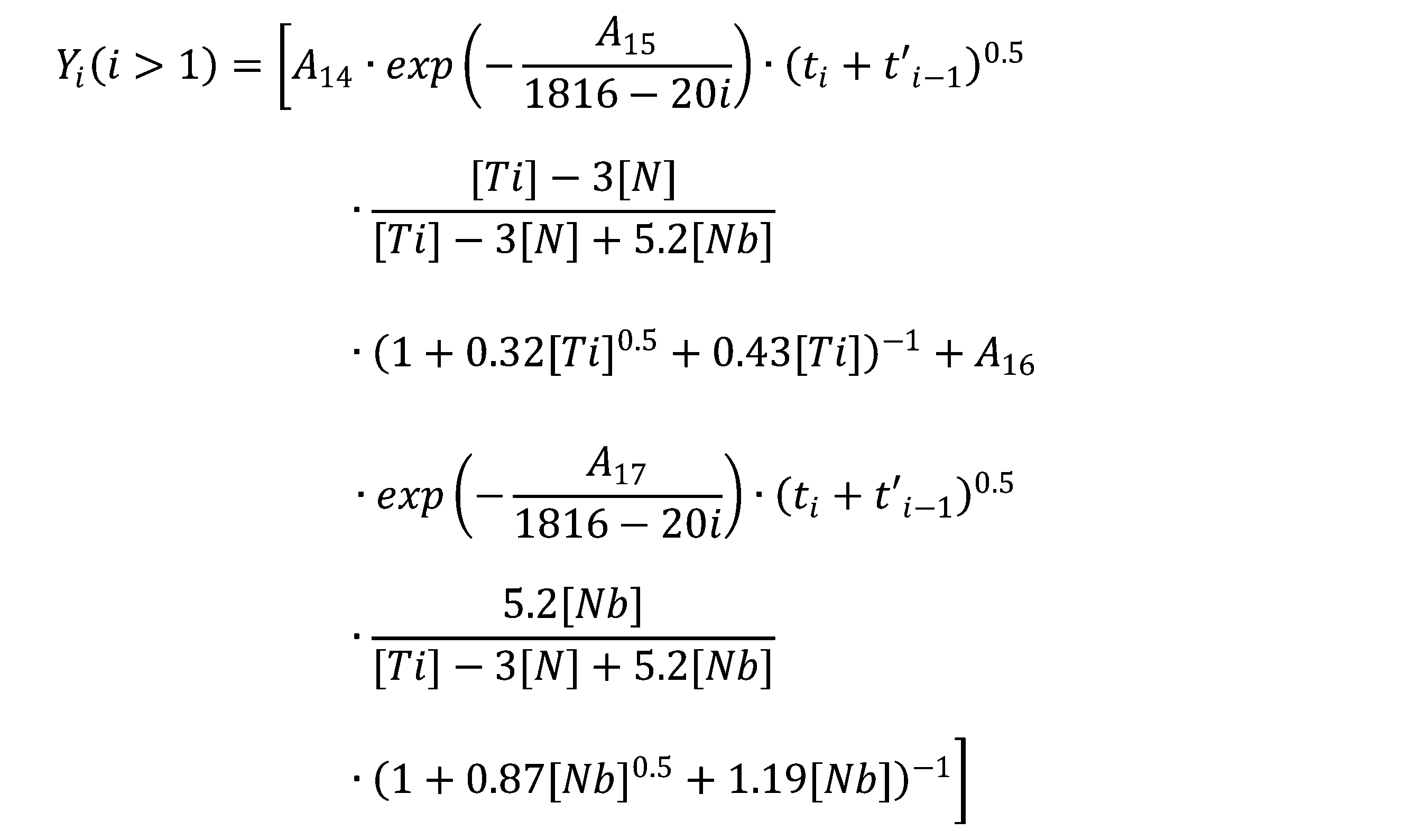
一方、P13を過度に高めると、セメンタイトが粗大化し、冷間圧延後の熱処理を経ても、溶解せずに残存する懸念がある。このことから、P13を1.00×10⁻⁷以下に制限する。セメンタイトの不要な粗大化を避けるため、P13は7.50×10⁻⁸以下とすることが好ましく、6.00×10⁻⁸以下とすることがより好ましい。冷間圧延を施す前であれば、鋼板の温度が500℃を下回ってから、再度500℃以上まで再加熱しても構わない。
続いて、室温まで冷却した鋼板に酸洗処理を施し、続けて冷間圧延を施す。冷間圧延における合計圧下率は30%以上、90%以下とする。冷間圧延における合計圧下率が30%未満では、その後の熱処理における再結晶の進行が不十分となり、未再結晶フェライトが残存する。また、組織を微細化して強度-成形性-耐衝撃性バランスを高める観点から、合計圧下率は40%以上であることが好ましく、50%以上であることがより好ましい。
一方、冷間圧延における合計圧下率が90%を超えると、鋼板の異方性が高まり、成形性が劣化する。成形性を高める観点からは、鋼板の異方性を低減するために、合計圧下率は80%以下であることが好ましく、70%以下であることがより好ましい。
冷間圧延において、鋼板の温度は加工発熱により上昇する。鋼板の温度が過剰に高まると、加工ひずみの蓄積が十分に進まず、再結晶の進行が阻害される場合がある。このため、冷間圧延の完了時点における鋼板の温度(冷間圧延完了温度)が250℃以下となるよう、圧下率およびパス間時間を制御する。成形性の観点から、再結晶を効率的に進めるには、冷間圧延の完了温度は200℃以下であることが好ましい。
[加熱過程]
続いて、冷間圧延後の鋼板(冷延鋼板)に熱処理(焼鈍)を行う。最初に最高加熱温度(焼鈍温度)まで加熱するが、その過程では加熱速度を制御し、再結晶を進める。400℃から550℃における平均加熱速度が3.0℃/秒未満であると、鋼板中の転位の回復が過剰に進行し、再結晶が抑制されるので、400~550℃の温度域における平均加熱速度は3.0℃/秒以上とする。平均加熱速度の上限は特に設定しないが、生産コストの観点から、200℃/秒以下とすることが好ましい。
続いて、550℃からAc1(℃)までの加熱において、温度履歴が式(5)を満たすように加熱する。
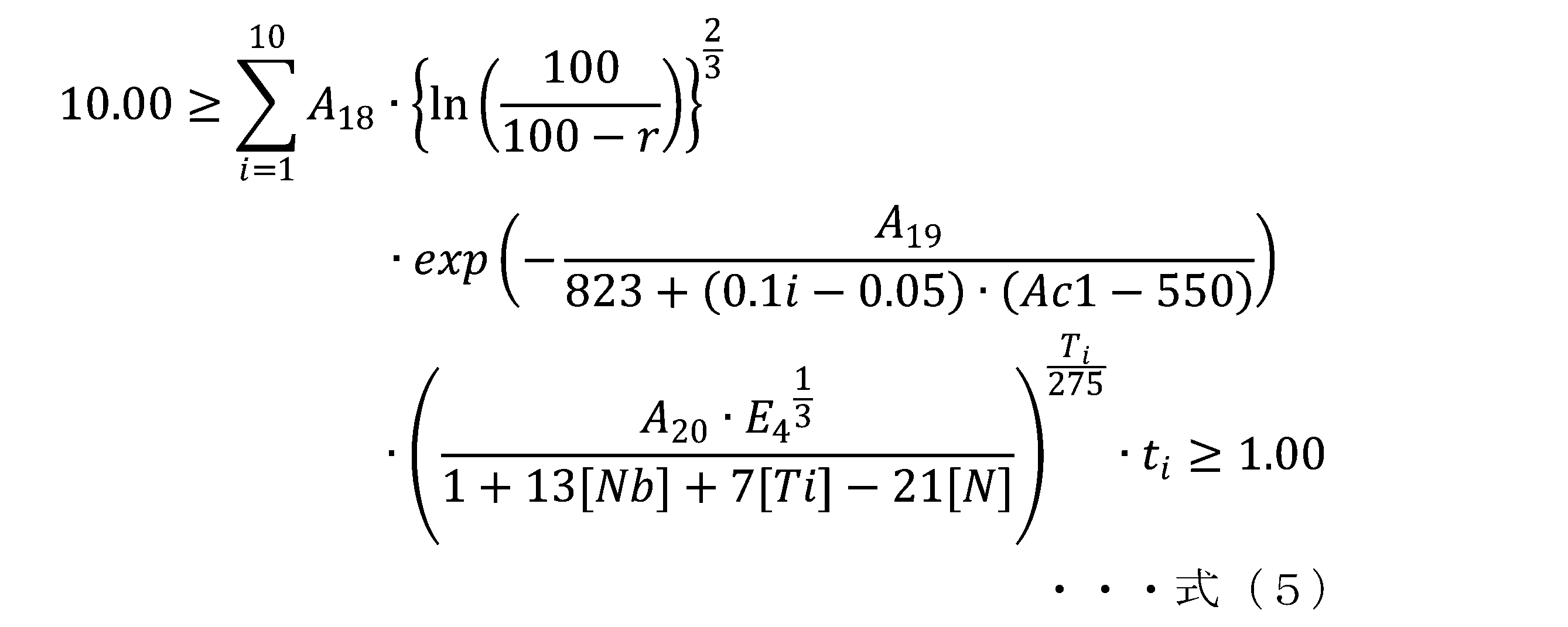
式(5)の中辺の値が1.00未満では、十分に再結晶が進行せず、成形性が劣化する。そのため、式(5)の中辺の値を1.00以上とする。成形性を高めることを目的として再結晶を十分に進めるには、式(5)の中辺の値は1.25以上とすることが好ましく、1.50以上とすることがより好ましい。一方、550℃からAc1までの温度域ではセメンタイトの減数成長が進む。式(5)の中辺の値が10.00を超えると、最終的に得られる鋼板に粗大なセメンタイトが残存するので、式(5)の中辺の上限を10.00とする。セメンタイトの粗大化を防ぐには、式(5)の中辺の値は7.00以下とすることが好ましく、5.00以下とすることがより好ましい。
一方、Ac1からAc1+20℃の温度域の平均加熱速度が速いと、セメンタイトが溶け残りやすくなり、耐衝撃性が劣化する。そのため、平均加熱速度は50℃/秒以下とし、30℃/秒以下とすることが好ましく、15℃/秒以下とすることがより好ましい。
Ac1+20℃から最高加熱温度までの加熱速度は特に規定しないが、オーステナイトを等方的に成長させるため、5.0℃/秒以下であることが好ましい。
一方、焼鈍温度がAc3+20℃を超えると、その後の冷却過程においてフェライトが生成するものの、フェライトの生成サイトがMn等の偏析によって偏るので、鋼板のマクロな均質性が損なわれる。よって、焼鈍温度はAc3+20℃以下とする。フェライト分率を高めて成形性を高める場合、焼鈍温度はAc3(℃)以下であることが好ましく、Ac3-20℃以下であることがより好ましい。
焼鈍温度における保持時間、すなわち、冷延した鋼板の加熱過程で最高加熱温度-10℃に到達してから、最高加熱温度(焼鈍温度)を経て再び最高加熱温度-10℃に到達するまでの時間は3.0秒以上とすることが好ましい。保持時間が過度に短いと、鋼板の内部における温度が十分に均質とならず、硬さの変動が大きくなって耐衝撃性が劣化する。この観点から、保持時間は10.0秒以上とすることがより好ましく、25.0秒以上とすることがさらに好ましい。保持時間の上限は特に設定しないが、200秒を超えて保持しても、鋼板のマクロな均質性はそれ以上高まらないことから、生産コストを鑑みて200秒以下とすることが好ましい。
最高加熱温度まで加熱し、保持時間を確保した後、冷却を施す。
冷却過程では、720~550℃の温度範囲における平均冷却速度が10℃/秒以上であり、550~(Ms-80)℃の温度範囲において、式(6)を満たし、Ms~(Ms-25)℃の温度範囲における平均冷却速度が10℃/秒以上であり、Ms~80℃の温度範囲において、式(7)を満たすように冷却を行う。
式(6)は、鋼板温度が550℃に到達した時点を起点とし、マルテンサイト変態開始温度(Ms)-80℃に到達した時点を終点として、その間の温度履歴を経過時間に対して10等分し、それぞれの時間範囲において計算を行う。
ベイナイト変態開始温度(Bs)[℃]、および、マルテンサイト変態開始温度(Ms)[℃]は、下記の式を用いて求める。
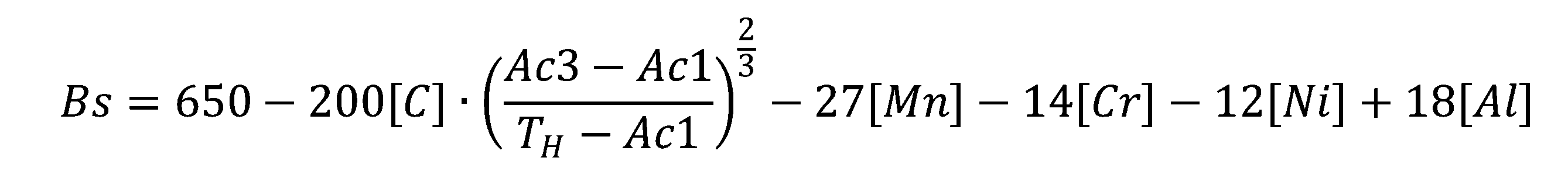
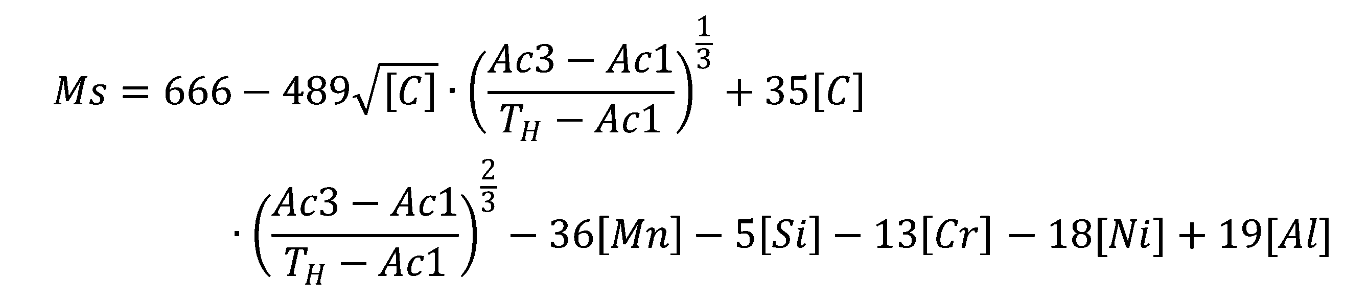
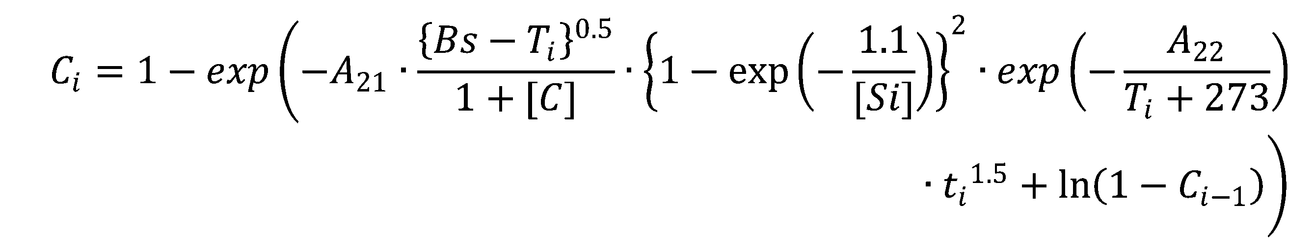

Ciは、計算開始からi番目の時間範囲における、ベイナイト変態の進行度合いを表す指標である。A21、A22は定数であり、それぞれ3.95×100、7.15×10³である。Bsはベイナイト変態開始温度[℃]である。Tiは当該時間範囲における平均温度[℃]である。[元素記号]([C]、[Si])は各成分の含有量[質量%]を示す。tiは各時間範囲における経過時間[秒]である。TiがBsを上回る場合、(Bs-Ti)項は0とする。また、C0は0とする。
Diは、計算開始からi番目の時間範囲における、ベイナイト変態に伴うセメンタイトの生成しやすさを表す指標である。A23、A24は定数であり、それぞれ、4.03×10⁻¹²、3.40×10⁻¹である。Tiは当該時間範囲における平均温度[℃]である。[元素記号]([Si]、[Al]、[Mo]、[Cr])は各成分の含有量[質量%]を示す。tiは各時間範囲における経過時間[秒]である。
式(6)の中辺はCiとDiの積の総和であり、式(6)の中辺の値が-2.00を下回る場合、未変態のオーステナイトに過剰に固溶炭素が蓄積し、室温まで冷却しても変態が完了せず、多量の残留オーステナイトを含む組織が形成され、耐衝撃性が劣化する。一方、式(6)の中辺の値が2.00を超えると、セメンタイトが過剰に生成して未変態オーステナイトからのベイナイト変態が過剰に進むため、十分な量のマルテンサイトが得られず、強度が低下する。以上の観点から、該温度域における温度履歴は式(6)を満たすものとする。式(6)の中辺の値は-1.30以上、1.30以下であることが好ましく、-0.80以上、0.80以下であることがより好ましい。
550℃からMs-80℃までの冷却過程において、式(6)を満たす温度履歴の範囲において、この間に鋼板に溶融亜鉛めっき処理あるいは溶融亜鉛合金めっき処理を施しても構わない。この際、めっき浴への浸漬前に鋼板を再加熱しても構わない。更に、式(6)を満たす温度履歴の範囲であれば、めっき処理後の鋼板を更に加熱し、めっき層の合金化処理を施しても構わない。
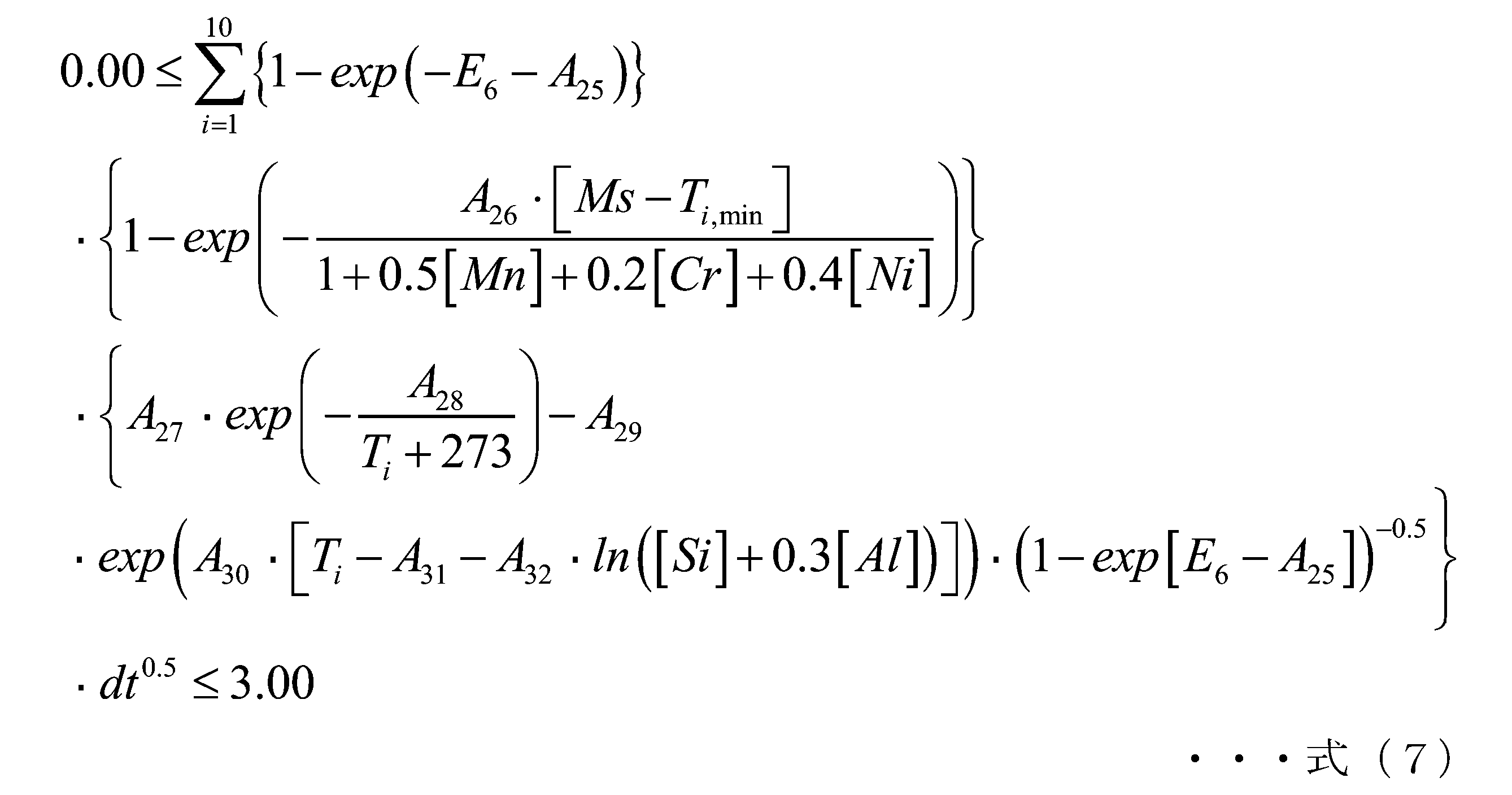
式(7)の中辺の値が0.00未満では、遷移炭化物の生成に十分な時間が得られないか、あるいは、セメンタイトの生成が優先される温度条件であるので、遷移炭化物の生成が過度に抑制され、十分な遷移炭化物が得られない。そのため、式(7)の中辺の値が0.00以上となるように冷却する。好ましくは0.20以上、より好ましくは0.40以上である。
一方、式(7)の中辺の値が3.00超では、遷移炭化物の一部からセメンタイトが生成し、遷移炭化物が減少して、十分な遷移炭化物が得られない。式(7)の中辺の値は2.50以下であることが好ましく、2.20以下であることが更に好ましい。
冷却終了後に、圧下率が3.00%以下の調質圧延を施しても良い。調質圧延を施すことで、マルテンサイトの内部に可動転位が導入され、その塑性変形は促進される。ただし、調質圧延の圧下率が3.00%超であると、塑性変形量が過大となり、均一伸びが大きく劣化するので、好ましくない。
熱処理中の雰囲気を制御し、鋼板の表面を改質しても構わない。例えば、脱炭雰囲気で加熱処理することで、鋼板表層部が適度に脱炭された曲げ性に優れた鋼板が得られる。
表1A、表1Bの残部はFe及び不純物である。
表2A~表2Dにおいて、「冷却速度1」は鋳片の冷却過程において、鋳片表面の温度が700~550℃における平均冷却速度を示す。熱間圧延工程における「冷却速度2」は熱間圧延完了から630℃までの間における平均冷却速度を示す。
表3A~表3Dにおいて、「加熱速度1」は、400~550℃における平均加熱速度を示す。「加熱速度2」は、Ac1~(Ac1+20)℃における平均加熱速度を示す。「冷却速度3」は720~550℃における平均冷却速度を示す。「冷却速度4」はMs~(Ms-25)℃における平均冷却速度を示す。
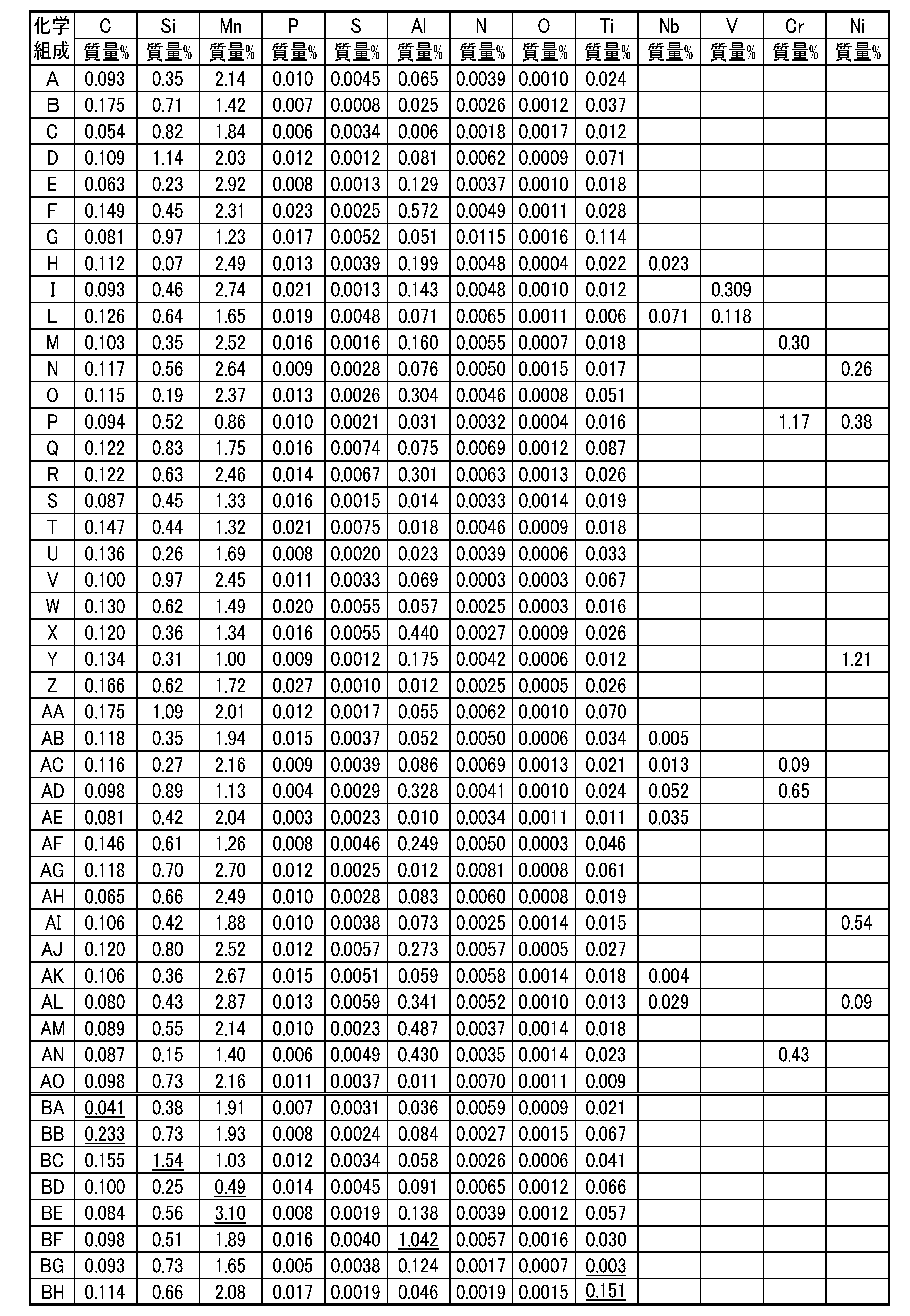

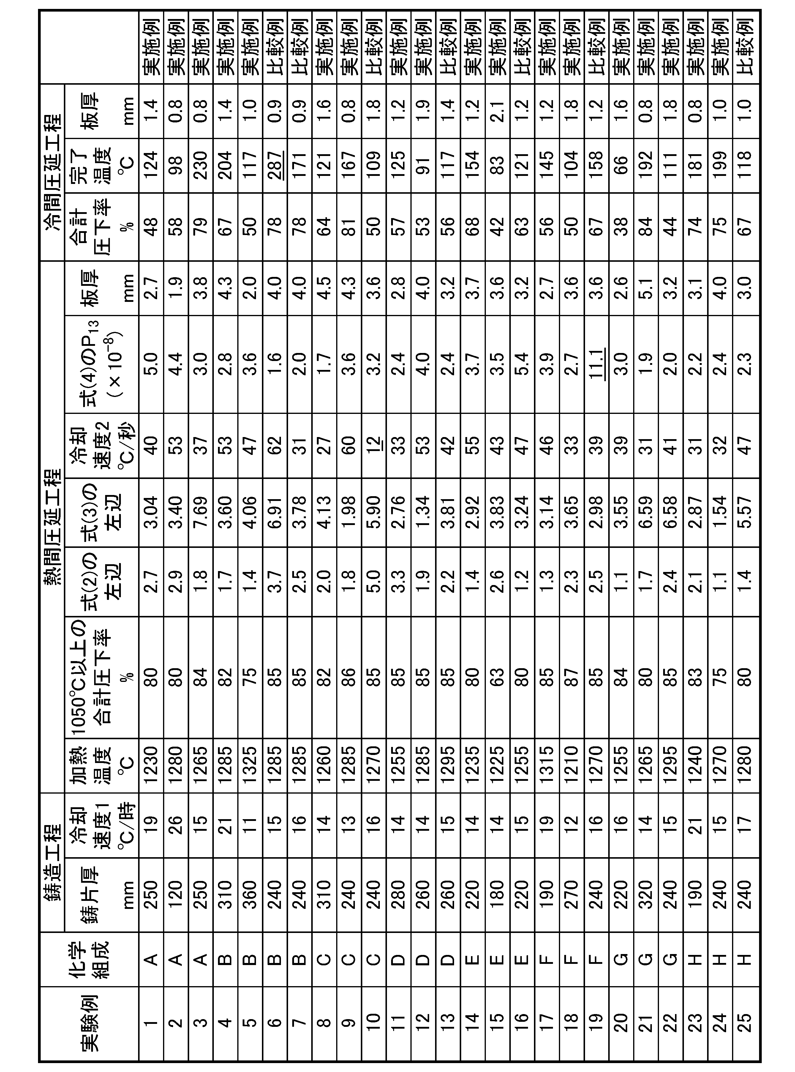

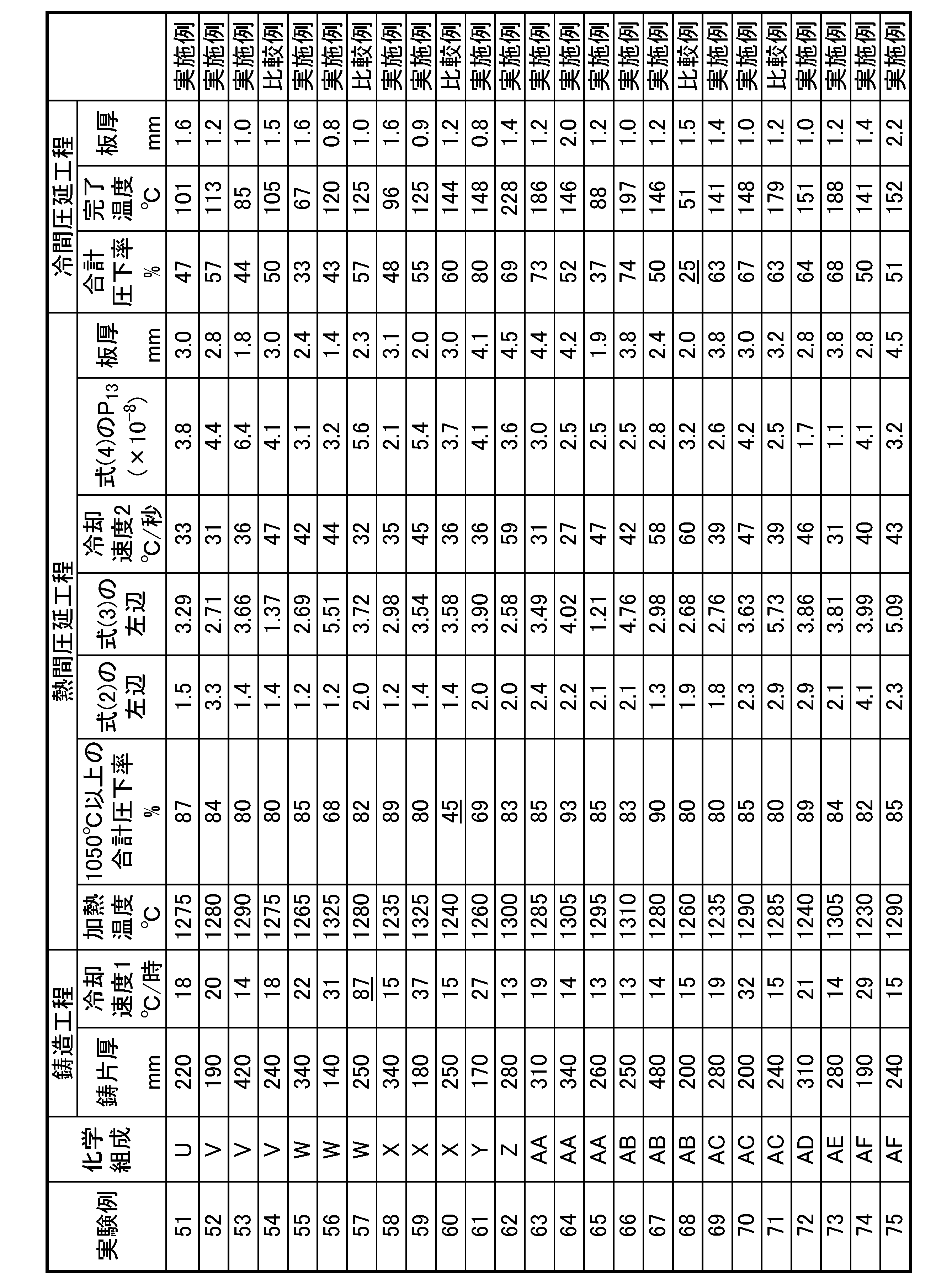
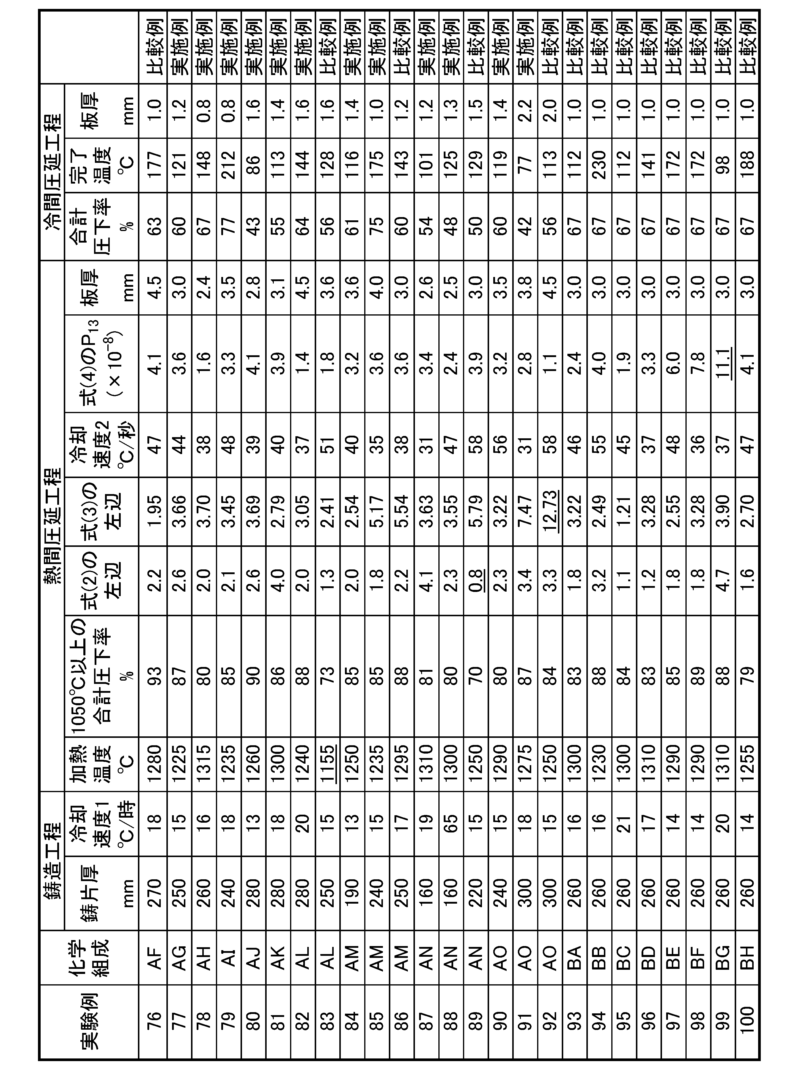
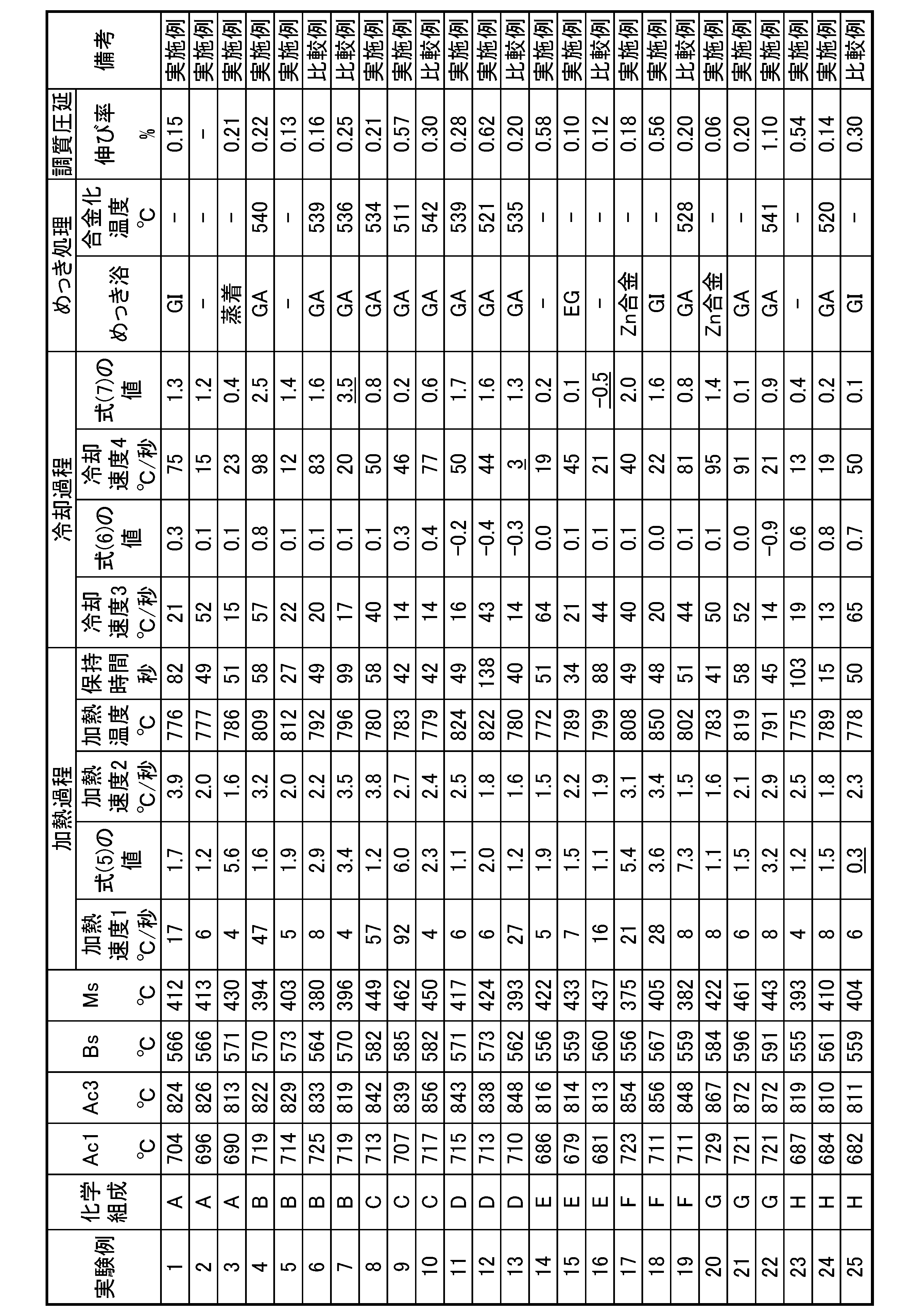
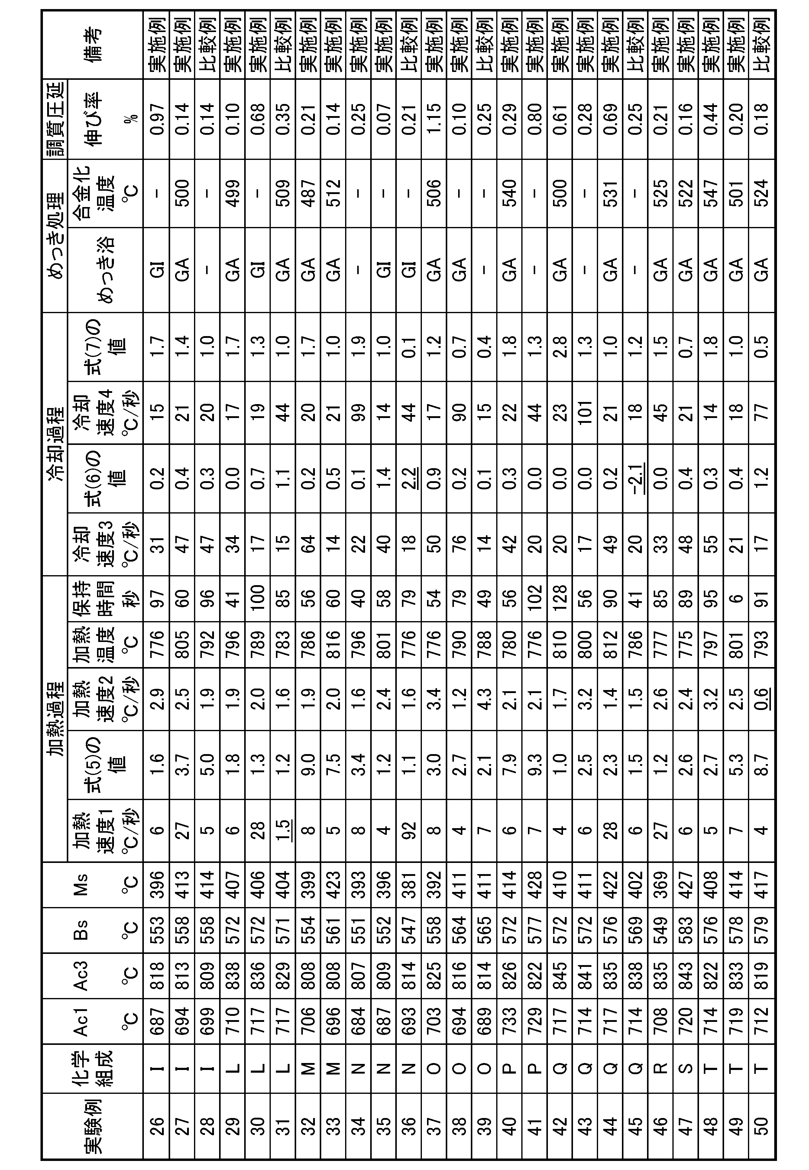
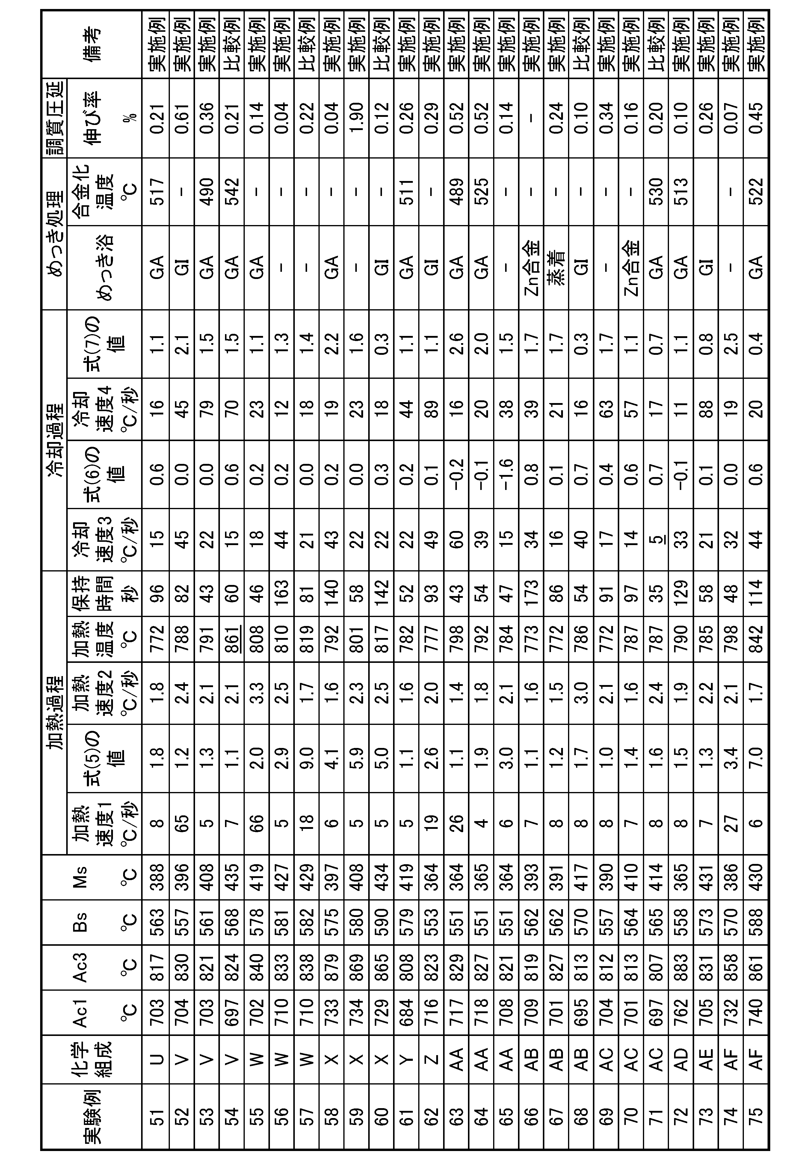

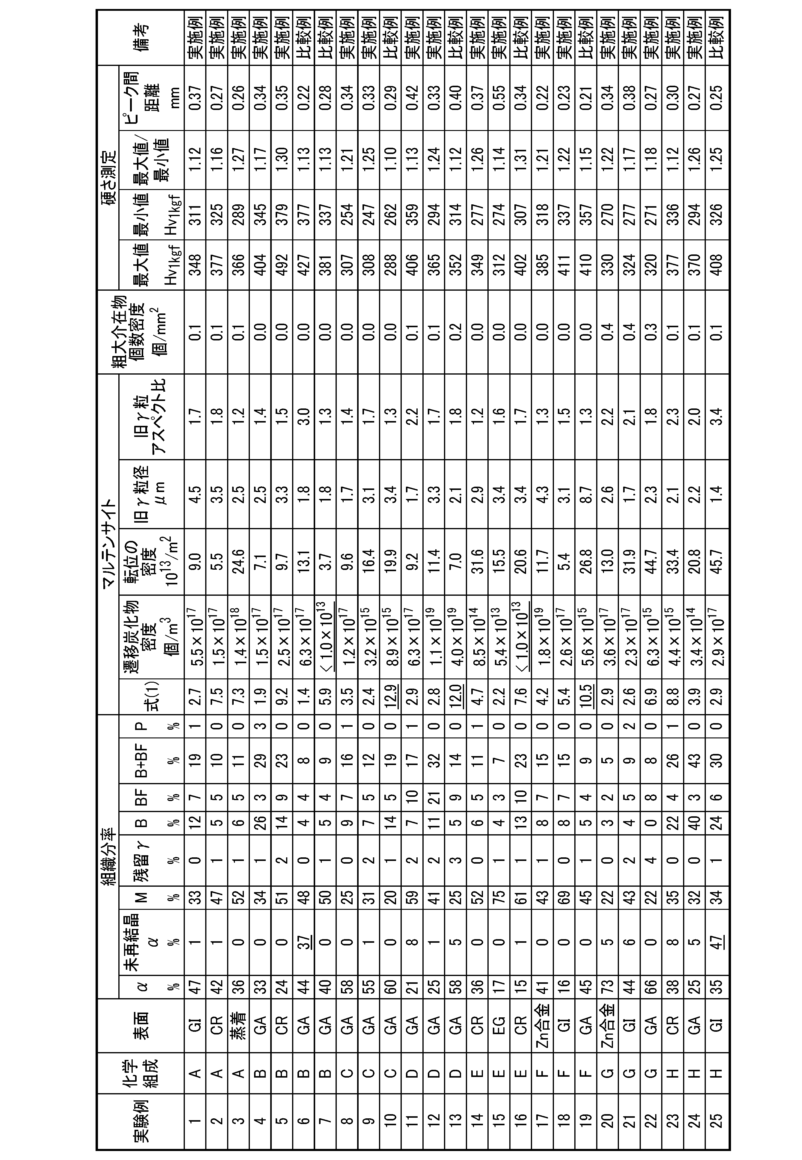
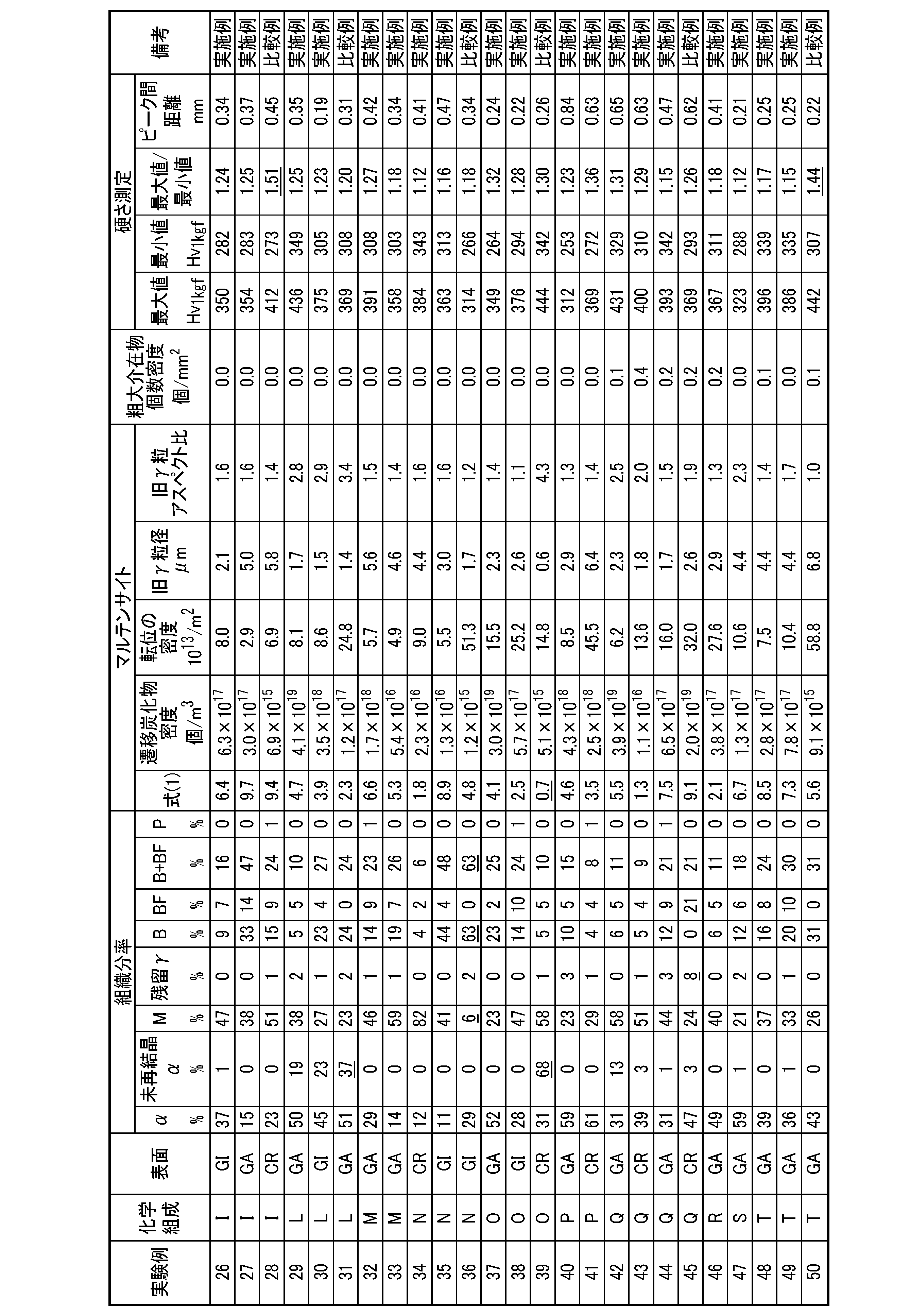
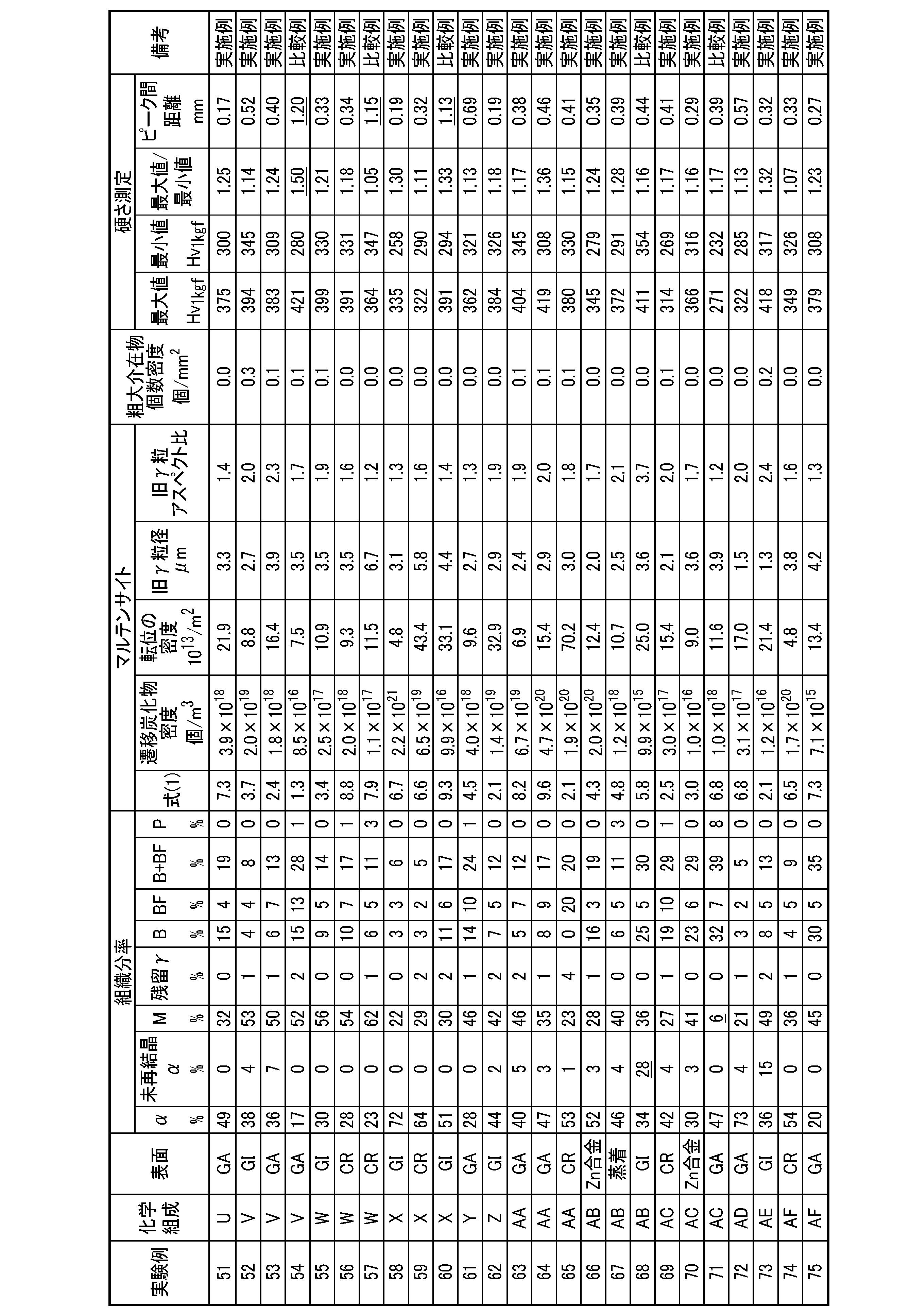
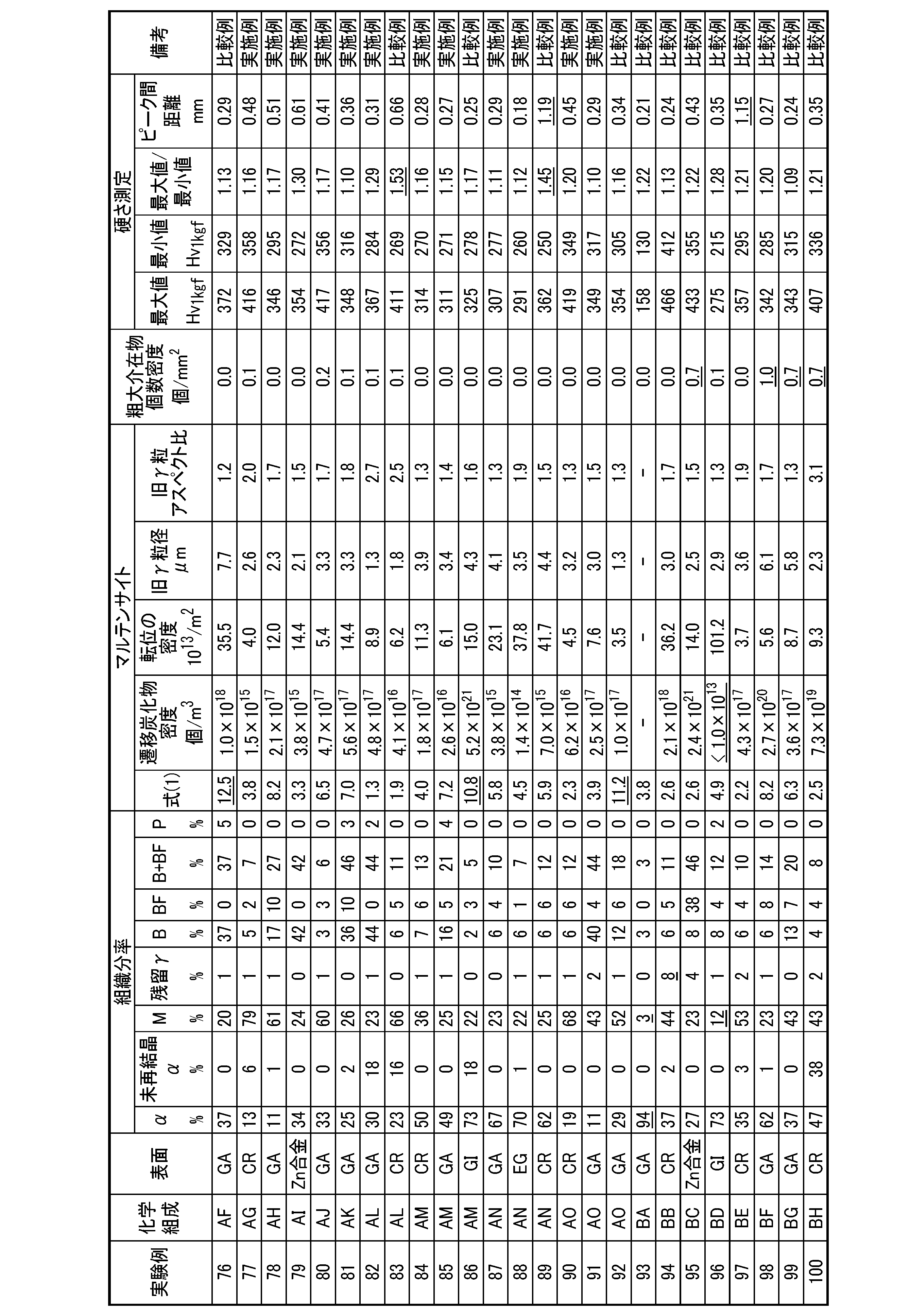
引張試験は、JIS Z 2241(2011)に記載の5号試験片を作製し、引張軸を鋼板の幅方向として、JIS Z 2241(2011)に従って行う。引張試験における引張強度が900MPa以上であることを前提として、引張強度(最大公称応力(TS:Tensile Strength))と均一伸び(UEL:Uniform Elongation)との値が下記の式(8)を満たす場合に、強度-成形性バランスに優れると判断する。
0.2%耐力を引張最大強度で除した降伏比が0.90以下の場合には、プレス成形時のスプリングバックが小さくなるため、より好ましいと判断する。

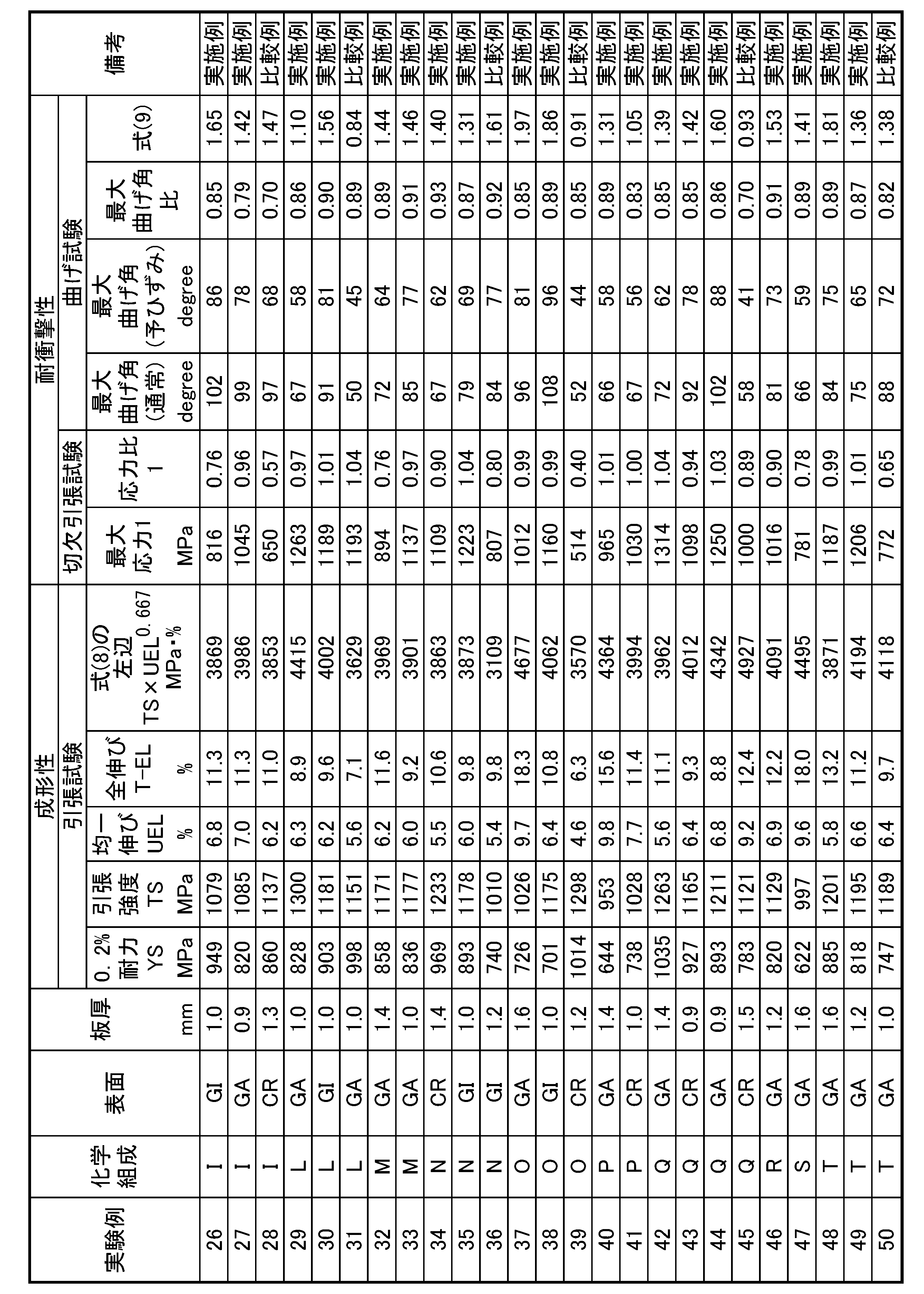
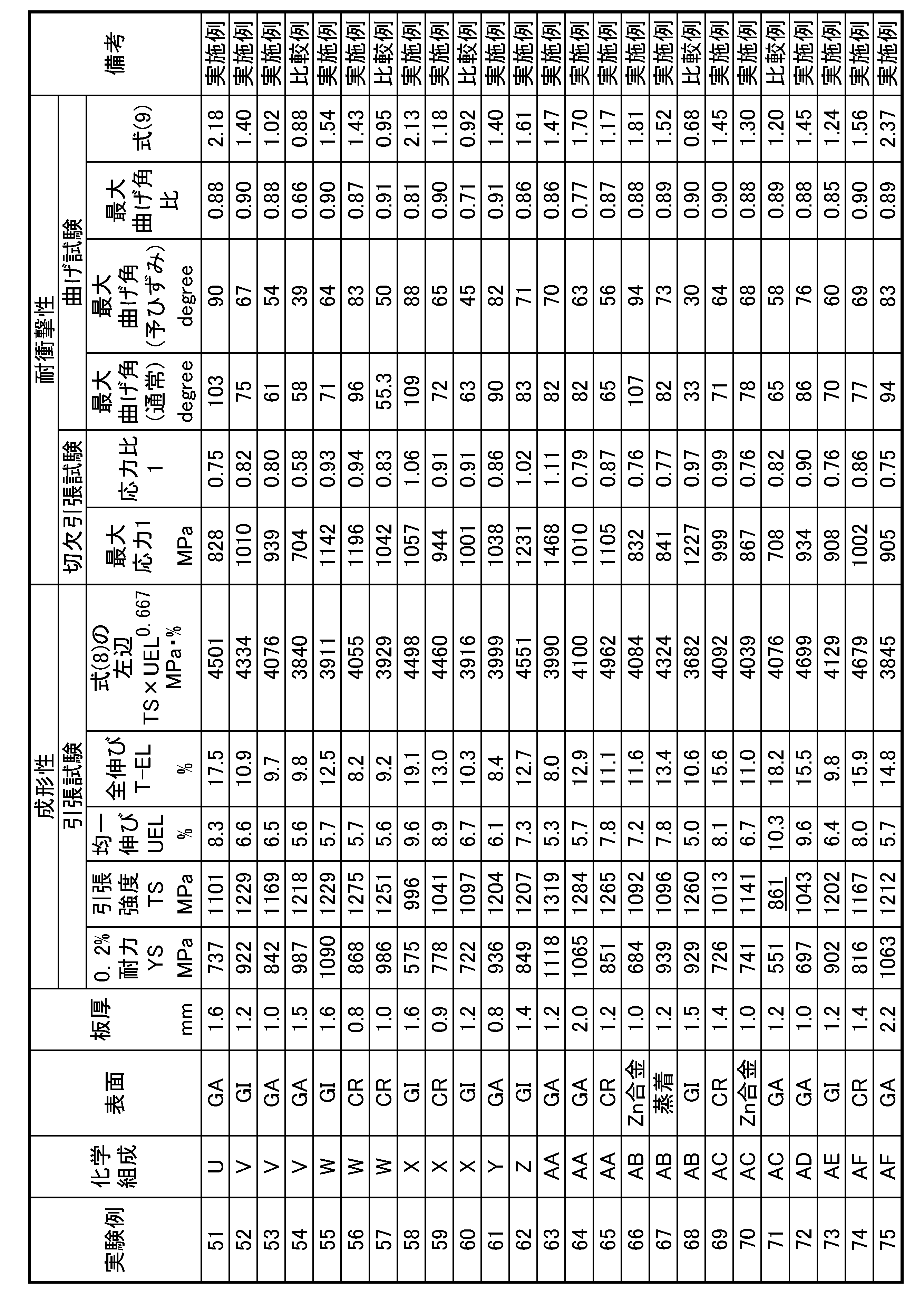

実験例93は、C含有量が少ない例であり、十分な量のマルテンサイトが得られない。その結果、十分な引張強度が得られない。
実験例94は、C含有量が過剰な例であり、残留オーステナイトが過剰に存在する。その結果、十分な耐衝撃性が得られない。
実験例95は、Si含有量が過剰な例であり、粗大介在物の密度が大きい。その結果、十分な耐衝撃性が得られない。
実験例96は、Mn含有量が少ない例であり、十分な量のマルテンサイトが得られない。その結果、十分な引張強度が得られない。
実験例97は、Mn含有量が過剰な例であり、鋼板のマクロな均質性が不足する。その結果、十分な耐衝撃性が得られない。
実験例98は、Al含有量が過剰な例であり、粗大介在物の密度が大きい。その結果、十分な耐衝撃性が得られない。
実験例99は、Ti含有量が少ない例であり、粗大介在物の密度が大きい。その結果、十分な耐衝撃性が得られない。
実験例100は、Ti含有量が過剰な例であり、粗大介在物の密度が大きい。その結果、十分な成形性が得られない。
実験例57は、鋳造工程における鋳片の冷却速度が速く、鋼板のマクロな均質性が不足する。その結果、十分な耐衝撃性が得られない。
実験例83は、熱間圧延工程における鋳片の加熱温度が低く、鋼板のマクロな均質性が不足する。その結果、十分な耐衝撃性が得られない。
実験例60は、熱間圧延工程における1050℃以上での合計圧下率が小さく、鋼板のマクロな均質性が不足する。その結果、十分な耐衝撃性が得られない。
実験例89は、熱間圧延工程における圧延条件からなる式(2)の左辺の値が小さく、鋼板のマクロな均質性が不足する。その結果、十分な耐衝撃性が得られない。
実験例92は、熱間圧延工程における圧延条件からなる式(3)の左辺の値が過大であり、粗大な炭化物の生成により式(1)の中辺の値が過大となる。その結果、十分な強度-成形性バランスが得られない。
実験例10は、熱間圧延工程における圧延後の冷却速度が小さく、粗大な炭化物の生成により式(1)の中辺の値が過大となる。その結果、十分な強度-成形性バランスが得られない。
実験例19は、熱間圧延工程における圧延後の冷却挙動を表す値、P13が過大となり式(4)を満たさず、粗大な炭化物の生成により式(1)の中辺の値が過大となる。その結果、十分な強度-成形性バランスが得られない。
実験例39は、熱間圧延工程における圧延後の冷却挙動を表す値、P13が過小となり式(4)を満たさず、冷間圧延後の熱処理における再結晶が十分に進行しない。その結果、十分な強度-成形性バランスおよび耐衝撃性が得られない。
実験例68は、冷間圧延工程における合計圧下率が小さく、冷間圧延後の熱処理における再結晶が十分に進行しない。その結果、十分な強度-成形性バランスおよび耐衝撃性が得られない。
実験例6は、冷間圧延工程における圧延完了温度が高く、冷間圧延後の熱処理における再結晶が十分に進行しない。その結果、十分な強度-成形性バランスおよび耐衝撃性が得られない。
実験例31は、熱処理工程における400℃から550℃における平均加熱速度が小さく、加熱中の再結晶が十分に進行しない。その結果、十分な強度-成形性バランスおよび耐衝撃性が得られない。
実験例76は、熱処理工程における加熱挙動を表す式(5)の中辺の値が過大であり、粗大な炭化物によって式(1)の中辺の値が過大となる。その結果、十分な強度-成形性バランスが得られない。
実験例25は、熱処理工程における加熱挙動を表す式(5)の中辺の値が過小であり、加熱中の再結晶が十分に進行しない。その結果、十分な強度-成形性バランスおよび耐衝撃性が得られない。
実験例50は、熱処理工程におけるAc1からAc1+20℃における平均加熱速度が小さく、鋼板のマクロな均質性が損なわれる。その結果、十分な耐衝撃性が得られない。
実験例54は、熱処理工程における加熱温度が高く、鋼板のマクロな均質性が損なわれる。その結果、十分な耐衝撃性が得られない。
実験例86は、熱処理工程における加熱温度が低く、粗大な炭化物の生成により式(1)の中辺の値が過大となる。その結果、十分な強度-成形性バランスが得られない。
実験例71は、熱処理工程における720℃から550℃における平均冷却速度が小さく、冷却中にパーライトが生成して、十分な量のマルテンサイトが得られない。その結果、引張強度が不足する。
実験例36は、熱処理工程における冷却挙動を表す式(6)の中辺の値が過大であり、ベイナイト変態が過剰に進行して、十分な量のマルテンサイトが得られない。その結果、十分な強度-成形性バランスが得られない。
実験例45は、熱処理工程における冷却挙動を表す式(6)の中辺の値が過小であり、ベイナイト変態に伴うオーステナイトへの炭素濃化が過剰に進行して、多量の残留オーステナイトが存在する。その結果、十分な耐衝撃性が得られない。
実験例13は、熱処理工程におけるMsからMs-25℃における冷却速度が小さく、粗大な炭化物の生成により式(1)の中辺の値が過大となる。その結果、十分な強度-成形性バランスが得られない。
実験例7は、熱処理工程における冷却挙動を表す式(7)の中辺の値が過大であり、マルテンサイト中の遷移炭化物が少ない。その結果、十分な耐衝撃性が得られない。
実験例16は、熱処理工程における冷却挙動を表す式(7)の中辺の値が過小である比較例であり、マルテンサイト中の遷移炭化物が少ない。その結果、十分な耐衝撃性が得られない。
実験例2、5、14、23、34、41、43、56、59、65、69、74、77、84、90は、めっき層を有さない、本発明の鋼板が得られる実施例である。実験例5および59は、熱間圧延工程後の鋼板を、冷間圧延前に、525℃まで再加熱してから冷却し、酸洗後に冷間圧延を施す実施例である。
Claims (13)
- 化学組成が、質量%で、
C:0.050%~0.180%、
Si:0.01%~1.20%、
Mn:0.80%~3.00%、
Al:0.005%~0.600%、
Ti:0.005%~0.120%、
P:0.050%以下、
S:0.0080%以下、
N:0.0125%以下、
O:0.0040%以下、
Nb:0~0.075%、
V:0~1.000%、
Cr:0~1.50%、
Ni:0~1.50%、
Cu:0~1.50%、
Mo:0~1.00%、
W:0~1.000%、
B:0~0.0060%、
Sn:0~1.000%、
Sb:0~0.200%、
Ca、Ce、Mg、Zr、La、REMの1種または2種以上の合計:0~0.0100%、
を含有し、残部がFeおよび不純物からなり、
表面から板厚方向に板厚の1/8の位置~前記表面から前記板厚方向に前記板厚の3/8の位置の範囲におけるミクロ組織が、体積分率で、
フェライト:10~75%、
マルテンサイト:20~90%、
残留オーステナイト:0~5%、
ベイナイトおよびベイニティックフェライトの合計:0~50%、
パーライト:0~5%、を含有し、
前記フェライトに占める未再結晶フェライトの割合が0~25%であり、
前記マルテンサイトに含まれるセメンタイトが、下記式(1)を満たし、
前記マルテンサイトに含まれる遷移炭化物の密度が1.0×10¹³個/m3以上であり、
円相当径10μm以上の粗大介在物の密度が0.50個/mm2以下であり、
前記表面から前記板厚方向に前記板厚の1/4の位置の前記表面と平行な面において、
ビッカース硬さの最大値Hvmaxと前記ビッカース硬さの最小値Hvminとの比が1.40以下であり、
前記ビッカース硬さの分布マップを作成したとき、前記ビッカース硬さのピーク同士の最小距離の平均値が1.00mm以下である
ことを特徴とする、鋼板。

- 前記化学組成が、質量%で、
Nb:0.005~0.075%、
V:0.010~1.000%、
Cr:0.05~1.50%、
Ni:0.05~1.50%、
Cu:0.05~1.50%、
Mo:0.03~1.00%、
W:0.030~1.000%、
B:0.0005~0.0060%、
Sn:0.010~1.000%、
Sb:0.005~0.200%、
Ca、Ce、Mg、Zr、La、REMの1種または2種以上の合計:0.0001~0.0100%、
からなる群から選択される1種または2種以上を含有する
ことを特徴とする請求項1に記載の鋼板。 - 前記ミクロ組織において、旧オーステナイト粒の平均粒径が5.0μm以下であり、かつ前記旧オーステナイト粒の平均アスペクト比が2.50以下である
ことを特徴とする、請求項1または2に記載の鋼板。 - 前記ミクロ組織に含まれる前記マルテンサイトが、1.0×10¹³/m2以上の転位を有する
ことを特徴とする、請求項1~3のいずれか一項に記載の鋼板。 - 前記表面に亜鉛めっき層が形成されていることを特徴とする請求項1~4のいずれか一項に記載の鋼板。
- 前記表面に亜鉛合金めっき層が形成されていることを特徴とする請求項1~4のいずれか一項に記載の鋼板。
- 前記亜鉛めっき層または前記亜鉛合金めっき層中のFe含有量が、質量%で、7.0%以上、13.0%以下であることを特徴とする、請求項5または6に記載の鋼板。
- 請求項1~4に記載の鋼板を製造する方法であって、
請求項1に記載の化学組成を有する溶鋼を、表面温度で700~550℃の範囲における平均冷却速度が10℃/時~75℃/時となるように鋳造して、厚さが100~500mm以下の鋳片を得る鋳造工程と、
前記鋳片を、1200~1350℃に加熱し、加熱後の前記鋳片を熱間圧延して熱延鋼板とする熱間圧延工程と、
前記熱延鋼板を、100℃以下まで冷却する冷却工程と、
前記熱延鋼板を、合計圧下率30~90%、冷間圧延完了温度が250℃以下となるように冷間圧延して冷延鋼板とする冷間圧延工程と、
前記冷延鋼板を、760℃以上、Ac3+20℃以下の焼鈍温度に加熱し、80℃以下まで冷却する焼鈍工程と、
を有し、
前記熱間圧延工程では、
1050℃以上で施す圧下において、式(2)を満たし、合計圧下率を60%以上とし、
1050℃未満で施す圧下において、式(3)を満たす圧延条件で施し、
前記冷却工程では、
前記熱間圧延の完了温度から630℃までの平均冷却速度を20℃/秒以上とし、
630~500℃の温度範囲において、式(4)を満たし、
前記焼鈍工程では、
前記焼鈍温度への加熱過程において、
400~550℃の温度範囲における平均加熱速度が3.0℃/秒以上であり、
550~Ac1℃の温度範囲において、式(5)を満たし、
Ac1~(Ac1+20)℃の温度範囲において、平均加熱速度が1.0℃/秒以上であり、
前記焼鈍温度からの冷却過程において、
720~550℃の温度範囲における平均冷却速度が10℃/秒以上であり、
550~(Ms-80)℃の温度範囲において、式(6)を満たし、
Ms~(Ms-25)℃の温度範囲における平均冷却速度が10℃/秒以上であり、
Ms~80℃の温度範囲において、式(7)を満たす
ことを特徴とする、鋼板の製造方法。


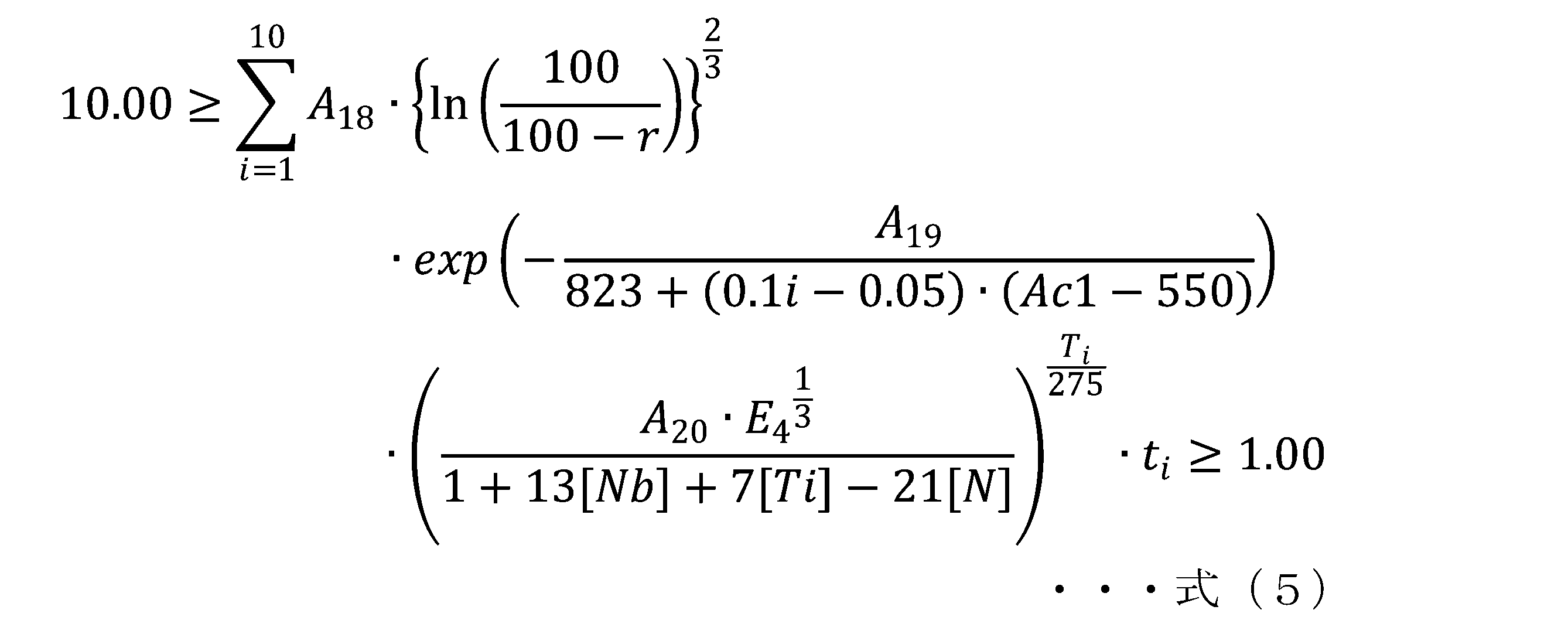


式(3)において、Rm+nは、1050℃以上での熱間圧延の総回数nと1050℃未満での熱間圧延の総回数mとを行った際の、1050℃未満の温度域における熱間圧延による組織の微細化挙動を表す指数である。
式(4)において、P13は、630℃から500℃までの温度域における析出の進行度合いを表す指標であり、
式(5)において、A18、A19、A20はいずれも定数であり、[Nb]、[Ti]、[N]は各元素の質量%での含有量を示し、tiは550℃から数えてi番目の温度域における単位秒での滞在時間を示し、E4は、式(4)で得られる値であり、
式(6)において、Ciは、計算開始からi番目の時間範囲における、ベイナイト変態の進行度合いを表す指標であり、Diは、計算開始からi番目の時間範囲における、ベイナイト変態に伴うセメンタイトの生成しやすさを表す指標である。
式(7)において、E6は前記式(6)の中辺の値であり、A25、A26、A27、A28、A29、A30、A31、A32は定数項であり、Msはマルテンサイト変態開始温度であり、Tiはi番目の時間範囲における平均温度である。Ti,minは前記Msに到達してからi番目の時間範囲までのTiのうち、最小の値である。また、[元素記号]は各元素の質量%での含有量を示し、dtは、単位秒での前記マルテンサイト変態開始温度に到達してから80℃に至るまでの経過時間を10等分した時間を示す。 - 前記焼鈍工程において、前記焼鈍温度での保持時間が3.0秒以上、200秒以下であることを特徴とする、請求項8に記載の鋼板の製造方法。
- 前記焼鈍工程の後に、伸び率が3.00%以下の調質圧延を行う調質圧延工程を含むことを特徴とする、請求項8または9に記載の鋼板の製造方法。
- 前記焼鈍工程の冷却過程において、前記冷延鋼板に溶融亜鉛めっき処理を施すことを特徴とする、
請求項8~10のいずれか一項に記載の鋼板の製造方法。 - 前記焼鈍工程の前記冷却過程において、前記冷延鋼板に溶融亜鉛合金めっき処理を施すことを特徴とする、
請求項8~10のいずれか一項に記載の鋼板の製造方法。 - 前記焼鈍工程の前記冷却過程において、前記溶融めっき処理後または前記溶融亜鉛合金めっき処理後に合金化処理を施すことを特徴とする、
請求項11または12に記載の鋼板の製造方法。
Priority Applications (6)
| Application Number | Priority Date | Filing Date | Title |
|---|---|---|---|
| CN202080023797.0A CN113614256B (zh) | 2019-04-11 | 2020-03-05 | 钢板及其制造方法 |
| EP20787223.5A EP3954792B1 (en) | 2019-04-11 | 2020-03-05 | Steel sheet and production method for same |
| JP2021513516A JP7243817B2 (ja) | 2019-04-11 | 2020-03-05 | 鋼板およびその製造方法 |
| MX2021011077A MX2021011077A (es) | 2019-04-11 | 2020-03-05 | Lamina de acero y metodo de produccion para la misma. |
| KR1020217028294A KR102638472B1 (ko) | 2019-04-11 | 2020-03-05 | 강판 및 그 제조 방법 |
| US17/437,369 US12252758B2 (en) | 2019-04-11 | 2020-03-05 | Steel sheet and production method for same |
Applications Claiming Priority (2)
| Application Number | Priority Date | Filing Date | Title |
|---|---|---|---|
| JP2019-075691 | 2019-04-11 | ||
| JP2019075691 | 2019-04-11 |
Publications (1)
| Publication Number | Publication Date |
|---|---|
| WO2020208979A1 true WO2020208979A1 (ja) | 2020-10-15 |
Family
ID=72751960
Family Applications (1)
| Application Number | Title | Priority Date | Filing Date |
|---|---|---|---|
| PCT/JP2020/009390 Ceased WO2020208979A1 (ja) | 2019-04-11 | 2020-03-05 | 鋼板およびその製造方法 |
Country Status (7)
| Country | Link |
|---|---|
| US (1) | US12252758B2 (ja) |
| EP (1) | EP3954792B1 (ja) |
| JP (1) | JP7243817B2 (ja) |
| KR (1) | KR102638472B1 (ja) |
| CN (1) | CN113614256B (ja) |
| MX (1) | MX2021011077A (ja) |
| WO (1) | WO2020208979A1 (ja) |
Cited By (10)
| Publication number | Priority date | Publication date | Assignee | Title |
|---|---|---|---|---|
| CN112593158A (zh) * | 2020-12-11 | 2021-04-02 | 湖南华菱涟源钢铁有限公司 | 690MPa耐低温超高强耐候钢板及制备方法 |
| WO2022138396A1 (ja) * | 2020-12-24 | 2022-06-30 | Jfeスチール株式会社 | 鋼板およびその製造方法 |
| KR20230049074A (ko) * | 2020-12-16 | 2023-04-12 | 주식회사 포스코 | 성형성이 우수한 고강도 냉연강판 및 그 제조 방법 |
| CN116601323A (zh) * | 2020-12-14 | 2023-08-15 | 浦项股份有限公司 | 弯曲性和成型性优异的高强度钢板及其制造方法 |
| JP2024535899A (ja) * | 2021-09-24 | 2024-10-02 | ポスコ カンパニー リミテッド | 表面品質に優れ、材質偏差が少ない高強度冷延鋼板及びこの製造方法 |
| EP4467671A4 (en) * | 2022-01-21 | 2025-03-12 | Nippon Steel Corporation | Steel sheet |
| CN119956251A (zh) * | 2025-02-14 | 2025-05-09 | 北京北冶功能材料有限公司 | 一种加工性能良好的超级铁素体不锈钢及制备方法和应用 |
| WO2025169959A1 (ja) * | 2024-02-05 | 2025-08-14 | 日本製鉄株式会社 | 鋼材及び機械構造用部品 |
| JP7806983B1 (ja) * | 2024-08-09 | 2026-01-27 | Jfeスチール株式会社 | 高強度鋼板及びその製造方法、高強度めっき鋼板及びその製造方法、部材及びその製造方法、並びに自動車の骨格構造部品又は自動車の補強部品 |
| WO2026033934A1 (ja) * | 2024-08-09 | 2026-02-12 | Jfeスチール株式会社 | 高強度鋼板及びその製造方法、高強度めっき鋼板及びその製造方法、部材及びその製造方法、並びに自動車の骨格構造部品又は自動車の補強部品 |
Families Citing this family (5)
| Publication number | Priority date | Publication date | Assignee | Title |
|---|---|---|---|---|
| US20250313914A1 (en) * | 2022-05-09 | 2025-10-09 | Jfe Steel Corporation | Slab for high-strength steel sheet and cooling method thereof, producing method of high-strength hot-rolled steel sheet, producing method of high-strength cold-rolled steel sheet, and producing method of high-strength plated steel sheet |
| KR102798279B1 (ko) * | 2022-09-16 | 2025-04-23 | 현대제철 주식회사 | 초고강도 냉연 강판 및 그 제조방법 |
| KR20250090473A (ko) * | 2023-12-12 | 2025-06-20 | 주식회사 포스코 | 강판 및 그 제조방법 |
| KR20250093735A (ko) * | 2023-12-15 | 2025-06-25 | 주식회사 포스코 | 강판 및 이의 제조방법 |
| KR20250093754A (ko) * | 2023-12-15 | 2025-06-25 | 주식회사 포스코 | 강판 및 이의 제조방법 |
Citations (9)
| Publication number | Priority date | Publication date | Assignee | Title |
|---|---|---|---|---|
| WO2005019487A1 (ja) * | 2003-08-26 | 2005-03-03 | Jfe Steel Corporation | 高張力冷延鋼板およびその製造方法 |
| JP2009019258A (ja) * | 2007-07-13 | 2009-01-29 | Nippon Steel Corp | 引張強度が700MPa以上で耐食性、穴拡げ性および延性に優れた合金化溶融亜鉛めっき高強度鋼板及びその製造方法 |
| WO2009096596A1 (ja) | 2008-01-31 | 2009-08-06 | Jfe Steel Corporation | 高強度鋼板およびその製造方法 |
| JP2011068979A (ja) * | 2009-08-24 | 2011-04-07 | Jfe Steel Corp | 部分焼戻し軟化鋼板およびその鋼板を用いたプレス成形部品 |
| JP2011111672A (ja) * | 2009-11-30 | 2011-06-09 | Nippon Steel Corp | 衝突吸収エネルギーに優れた引張最大強度900MPa以上の高強度冷延鋼板及びその製造方法、並びに、高強度亜鉛めっき鋼板及びその製造方法 |
| JP5659929B2 (ja) | 2011-04-11 | 2015-01-28 | 新日鐵住金株式会社 | 冷延鋼板及びその製造方法 |
| WO2017131054A1 (ja) * | 2016-01-29 | 2017-08-03 | Jfeスチール株式会社 | 高強度亜鉛めっき鋼板、高強度部材及び高強度亜鉛めっき鋼板の製造方法 |
| WO2018030503A1 (ja) | 2016-08-10 | 2018-02-15 | Jfeスチール株式会社 | 薄鋼板およびその製造方法 |
| JP2019075691A (ja) | 2017-10-16 | 2019-05-16 | 富士通株式会社 | ミラーパケット制御プログラム、ミラーパケット制御方法、およびミラーパケット制御装置 |
Family Cites Families (9)
| Publication number | Priority date | Publication date | Assignee | Title |
|---|---|---|---|---|
| EP2508640B1 (en) * | 2009-11-30 | 2019-09-11 | Nippon Steel Corporation | High-strength steel sheet having excellent hydrogen embrittlement resistance and ultimate tensile strength of 900 mpa or more, and process for production thereof |
| JP5699860B2 (ja) * | 2011-08-24 | 2015-04-15 | 新日鐵住金株式会社 | 溶融亜鉛めっき鋼板およびその製造方法 |
| US10144996B2 (en) * | 2012-12-18 | 2018-12-04 | Jfe Steel Corporation | High strength cold rolled steel sheet with low yield ratio and method of manufacturing the same |
| KR101730756B1 (ko) | 2013-08-30 | 2017-04-26 | 신닛테츠스미킨 카부시키카이샤 | 내사워성, 내압궤 특성 및 저온 인성이 우수한 후육 고강도 라인 파이프용 강판과 라인 파이프 |
| EP3054025B1 (en) * | 2013-12-18 | 2018-02-21 | JFE Steel Corporation | High-strength galvanized steel sheet and method for manufacturing the same |
| WO2016129214A1 (ja) * | 2015-02-13 | 2016-08-18 | Jfeスチール株式会社 | 高強度溶融亜鉛めっき鋼板及びその製造方法 |
| JP6554396B2 (ja) * | 2015-03-31 | 2019-07-31 | 株式会社神戸製鋼所 | 加工性および衝突特性に優れた引張強度が980MPa以上の高強度冷延鋼板、およびその製造方法 |
| CN107849652B (zh) * | 2015-07-31 | 2020-04-03 | 日本制铁株式会社 | 加工诱发相变型复合组织钢板及其制造方法 |
| MX2018007364A (es) * | 2016-03-25 | 2018-08-15 | Nippon Steel & Sumitomo Metal Corp | Lamina de acero de alta resistencia y lamina de acero galvanizada de alta resistencia. |
-
2020
- 2020-03-05 MX MX2021011077A patent/MX2021011077A/es unknown
- 2020-03-05 CN CN202080023797.0A patent/CN113614256B/zh active Active
- 2020-03-05 EP EP20787223.5A patent/EP3954792B1/en active Active
- 2020-03-05 KR KR1020217028294A patent/KR102638472B1/ko active Active
- 2020-03-05 JP JP2021513516A patent/JP7243817B2/ja active Active
- 2020-03-05 WO PCT/JP2020/009390 patent/WO2020208979A1/ja not_active Ceased
- 2020-03-05 US US17/437,369 patent/US12252758B2/en active Active
Patent Citations (9)
| Publication number | Priority date | Publication date | Assignee | Title |
|---|---|---|---|---|
| WO2005019487A1 (ja) * | 2003-08-26 | 2005-03-03 | Jfe Steel Corporation | 高張力冷延鋼板およびその製造方法 |
| JP2009019258A (ja) * | 2007-07-13 | 2009-01-29 | Nippon Steel Corp | 引張強度が700MPa以上で耐食性、穴拡げ性および延性に優れた合金化溶融亜鉛めっき高強度鋼板及びその製造方法 |
| WO2009096596A1 (ja) | 2008-01-31 | 2009-08-06 | Jfe Steel Corporation | 高強度鋼板およびその製造方法 |
| JP2011068979A (ja) * | 2009-08-24 | 2011-04-07 | Jfe Steel Corp | 部分焼戻し軟化鋼板およびその鋼板を用いたプレス成形部品 |
| JP2011111672A (ja) * | 2009-11-30 | 2011-06-09 | Nippon Steel Corp | 衝突吸収エネルギーに優れた引張最大強度900MPa以上の高強度冷延鋼板及びその製造方法、並びに、高強度亜鉛めっき鋼板及びその製造方法 |
| JP5659929B2 (ja) | 2011-04-11 | 2015-01-28 | 新日鐵住金株式会社 | 冷延鋼板及びその製造方法 |
| WO2017131054A1 (ja) * | 2016-01-29 | 2017-08-03 | Jfeスチール株式会社 | 高強度亜鉛めっき鋼板、高強度部材及び高強度亜鉛めっき鋼板の製造方法 |
| WO2018030503A1 (ja) | 2016-08-10 | 2018-02-15 | Jfeスチール株式会社 | 薄鋼板およびその製造方法 |
| JP2019075691A (ja) | 2017-10-16 | 2019-05-16 | 富士通株式会社 | ミラーパケット制御プログラム、ミラーパケット制御方法、およびミラーパケット制御装置 |
Non-Patent Citations (1)
| Title |
|---|
| See also references of EP3954792A4 |
Cited By (14)
| Publication number | Priority date | Publication date | Assignee | Title |
|---|---|---|---|---|
| CN112593158B (zh) * | 2020-12-11 | 2021-11-30 | 湖南华菱涟源钢铁有限公司 | 690MPa耐低温超高强耐候钢板及制备方法 |
| CN112593158A (zh) * | 2020-12-11 | 2021-04-02 | 湖南华菱涟源钢铁有限公司 | 690MPa耐低温超高强耐候钢板及制备方法 |
| CN116601323A (zh) * | 2020-12-14 | 2023-08-15 | 浦项股份有限公司 | 弯曲性和成型性优异的高强度钢板及其制造方法 |
| KR102784307B1 (ko) * | 2020-12-16 | 2025-03-19 | 주식회사 포스코 | 성형성이 우수한 고강도 냉연강판 및 그 제조 방법 |
| KR20230049074A (ko) * | 2020-12-16 | 2023-04-12 | 주식회사 포스코 | 성형성이 우수한 고강도 냉연강판 및 그 제조 방법 |
| WO2022138396A1 (ja) * | 2020-12-24 | 2022-06-30 | Jfeスチール株式会社 | 鋼板およびその製造方法 |
| JP7151936B1 (ja) * | 2020-12-24 | 2022-10-12 | Jfeスチール株式会社 | 鋼板およびその製造方法 |
| US12410502B2 (en) | 2020-12-24 | 2025-09-09 | Jfe Steel Corporation | Steel sheet and production method therefor |
| JP2024535899A (ja) * | 2021-09-24 | 2024-10-02 | ポスコ カンパニー リミテッド | 表面品質に優れ、材質偏差が少ない高強度冷延鋼板及びこの製造方法 |
| EP4467671A4 (en) * | 2022-01-21 | 2025-03-12 | Nippon Steel Corporation | Steel sheet |
| WO2025169959A1 (ja) * | 2024-02-05 | 2025-08-14 | 日本製鉄株式会社 | 鋼材及び機械構造用部品 |
| JP7806983B1 (ja) * | 2024-08-09 | 2026-01-27 | Jfeスチール株式会社 | 高強度鋼板及びその製造方法、高強度めっき鋼板及びその製造方法、部材及びその製造方法、並びに自動車の骨格構造部品又は自動車の補強部品 |
| WO2026033934A1 (ja) * | 2024-08-09 | 2026-02-12 | Jfeスチール株式会社 | 高強度鋼板及びその製造方法、高強度めっき鋼板及びその製造方法、部材及びその製造方法、並びに自動車の骨格構造部品又は自動車の補強部品 |
| CN119956251A (zh) * | 2025-02-14 | 2025-05-09 | 北京北冶功能材料有限公司 | 一种加工性能良好的超级铁素体不锈钢及制备方法和应用 |
Also Published As
| Publication number | Publication date |
|---|---|
| JPWO2020208979A1 (ja) | 2021-12-16 |
| MX2021011077A (es) | 2021-10-22 |
| US12252758B2 (en) | 2025-03-18 |
| JP7243817B2 (ja) | 2023-03-22 |
| CN113614256A (zh) | 2021-11-05 |
| EP3954792A4 (en) | 2023-07-19 |
| KR20210123371A (ko) | 2021-10-13 |
| CN113614256B (zh) | 2023-03-21 |
| EP3954792B1 (en) | 2025-11-19 |
| EP3954792A1 (en) | 2022-02-16 |
| KR102638472B1 (ko) | 2024-02-21 |
| US20220154302A1 (en) | 2022-05-19 |
Similar Documents
| Publication | Publication Date | Title |
|---|---|---|
| JP7243817B2 (ja) | 鋼板およびその製造方法 | |
| JP5352793B2 (ja) | 耐遅れ破壊特性に優れた高強度溶融亜鉛めっき鋼板およびその製造方法 | |
| CN109072381B (zh) | 高强度钢板及其制造方法 | |
| JP6566026B2 (ja) | めっき鋼板 | |
| KR101632778B1 (ko) | 냉연 강판 및 그 제조 방법 | |
| KR102220940B1 (ko) | 강판 및 도금 강판 | |
| JP5240421B1 (ja) | 耐衝撃特性に優れた高強度鋼板およびその製造方法、高強度亜鉛めっき鋼板およびその製造方法 | |
| JP6597939B1 (ja) | 成形性及び耐衝撃性に優れた高強度鋼板、及び、成形性及び耐衝撃性に優れた高強度鋼板の製造方法 | |
| KR20210108461A (ko) | 용융 아연 도금 강판 및 그 제조 방법 | |
| KR102649517B1 (ko) | 강판 및 그 제조 방법 | |
| WO2020121417A1 (ja) | 成形性、靱性、及び、溶接性に優れた高強度鋼板、及び、その製造方法 | |
| KR102742082B1 (ko) | 강판 및 그의 제조 방법 | |
| CN110520550A (zh) | 高强度热浸镀锌钢板及其制造方法 | |
| US20250369064A1 (en) | Steel sheet and method of manufacturing the same | |
| KR102755080B1 (ko) | 강판 및 그 제조 방법 |
Legal Events
| Date | Code | Title | Description |
|---|---|---|---|
| 121 | Ep: the epo has been informed by wipo that ep was designated in this application |
Ref document number: 20787223 Country of ref document: EP Kind code of ref document: A1 |
|
| ENP | Entry into the national phase |
Ref document number: 2021513516 Country of ref document: JP Kind code of ref document: A |
|
| ENP | Entry into the national phase |
Ref document number: 20217028294 Country of ref document: KR Kind code of ref document: A |
|
| NENP | Non-entry into the national phase |
Ref country code: DE |
|
| ENP | Entry into the national phase |
Ref document number: 2020787223 Country of ref document: EP Effective date: 20211111 |
|
| WWG | Wipo information: grant in national office |
Ref document number: 17437369 Country of ref document: US |
|
| WWG | Wipo information: grant in national office |
Ref document number: MX/A/2021/011077 Country of ref document: MX |
|
| WWG | Wipo information: grant in national office |
Ref document number: 2020787223 Country of ref document: EP |