WO2020209200A1 - 電池システム、鉄道車両および電池管理方法 - Google Patents
電池システム、鉄道車両および電池管理方法 Download PDFInfo
- Publication number
- WO2020209200A1 WO2020209200A1 PCT/JP2020/015341 JP2020015341W WO2020209200A1 WO 2020209200 A1 WO2020209200 A1 WO 2020209200A1 JP 2020015341 W JP2020015341 W JP 2020015341W WO 2020209200 A1 WO2020209200 A1 WO 2020209200A1
- Authority
- WO
- WIPO (PCT)
- Prior art keywords
- battery
- life
- current
- usage conditions
- shortage
- Prior art date
- Legal status (The legal status is an assumption and is not a legal conclusion. Google has not performed a legal analysis and makes no representation as to the accuracy of the status listed.)
- Ceased
Links
Images



Classifications
-
- H—ELECTRICITY
- H01—ELECTRIC ELEMENTS
- H01M—PROCESSES OR MEANS, e.g. BATTERIES, FOR THE DIRECT CONVERSION OF CHEMICAL ENERGY INTO ELECTRICAL ENERGY
- H01M10/00—Secondary cells; Manufacture thereof
- H01M10/42—Methods or arrangements for servicing or maintenance of secondary cells or secondary half-cells
- H01M10/48—Accumulators combined with arrangements for measuring, testing or indicating the condition of cells, e.g. the level or density of the electrolyte
-
- H—ELECTRICITY
- H01—ELECTRIC ELEMENTS
- H01M—PROCESSES OR MEANS, e.g. BATTERIES, FOR THE DIRECT CONVERSION OF CHEMICAL ENERGY INTO ELECTRICAL ENERGY
- H01M10/00—Secondary cells; Manufacture thereof
- H01M10/42—Methods or arrangements for servicing or maintenance of secondary cells or secondary half-cells
- H01M10/425—Structural combination with electronic components, e.g. electronic circuits integrated to the outside of the casing
-
- B—PERFORMING OPERATIONS; TRANSPORTING
- B60—VEHICLES IN GENERAL
- B60L—PROPULSION OF ELECTRICALLY-PROPELLED VEHICLES; SUPPLYING ELECTRIC POWER FOR AUXILIARY EQUIPMENT OF ELECTRICALLY-PROPELLED VEHICLES; ELECTRODYNAMIC BRAKE SYSTEMS FOR VEHICLES IN GENERAL; MAGNETIC SUSPENSION OR LEVITATION FOR VEHICLES; MONITORING OPERATING VARIABLES OF ELECTRICALLY-PROPELLED VEHICLES; ELECTRIC SAFETY DEVICES FOR ELECTRICALLY-PROPELLED VEHICLES
- B60L50/00—Electric propulsion with power supplied within the vehicle
- B60L50/50—Electric propulsion with power supplied within the vehicle using propulsion power supplied by batteries or fuel cells
- B60L50/60—Electric propulsion with power supplied within the vehicle using propulsion power supplied by batteries or fuel cells using power supplied by batteries
- B60L50/61—Electric propulsion with power supplied within the vehicle using propulsion power supplied by batteries or fuel cells using power supplied by batteries by batteries charged by engine-driven generators, e.g. series hybrid electric vehicles
-
- B—PERFORMING OPERATIONS; TRANSPORTING
- B60—VEHICLES IN GENERAL
- B60L—PROPULSION OF ELECTRICALLY-PROPELLED VEHICLES; SUPPLYING ELECTRIC POWER FOR AUXILIARY EQUIPMENT OF ELECTRICALLY-PROPELLED VEHICLES; ELECTRODYNAMIC BRAKE SYSTEMS FOR VEHICLES IN GENERAL; MAGNETIC SUSPENSION OR LEVITATION FOR VEHICLES; MONITORING OPERATING VARIABLES OF ELECTRICALLY-PROPELLED VEHICLES; ELECTRIC SAFETY DEVICES FOR ELECTRICALLY-PROPELLED VEHICLES
- B60L58/00—Methods or circuit arrangements for monitoring or controlling batteries or fuel cells, specially adapted for electric vehicles
- B60L58/10—Methods or circuit arrangements for monitoring or controlling batteries or fuel cells, specially adapted for electric vehicles for monitoring or controlling batteries
- B60L58/16—Methods or circuit arrangements for monitoring or controlling batteries or fuel cells, specially adapted for electric vehicles for monitoring or controlling batteries responding to battery ageing, e.g. to the number of charging cycles or the state of health [SoH]
-
- H—ELECTRICITY
- H01—ELECTRIC ELEMENTS
- H01M—PROCESSES OR MEANS, e.g. BATTERIES, FOR THE DIRECT CONVERSION OF CHEMICAL ENERGY INTO ELECTRICAL ENERGY
- H01M10/00—Secondary cells; Manufacture thereof
- H01M10/42—Methods or arrangements for servicing or maintenance of secondary cells or secondary half-cells
- H01M10/44—Methods for charging or discharging
- H01M10/441—Methods for charging or discharging for several batteries or cells simultaneously or sequentially
-
- H—ELECTRICITY
- H01—ELECTRIC ELEMENTS
- H01M—PROCESSES OR MEANS, e.g. BATTERIES, FOR THE DIRECT CONVERSION OF CHEMICAL ENERGY INTO ELECTRICAL ENERGY
- H01M10/00—Secondary cells; Manufacture thereof
- H01M10/42—Methods or arrangements for servicing or maintenance of secondary cells or secondary half-cells
- H01M10/44—Methods for charging or discharging
- H01M10/443—Methods for charging or discharging in response to temperature
-
- H—ELECTRICITY
- H01—ELECTRIC ELEMENTS
- H01M—PROCESSES OR MEANS, e.g. BATTERIES, FOR THE DIRECT CONVERSION OF CHEMICAL ENERGY INTO ELECTRICAL ENERGY
- H01M10/00—Secondary cells; Manufacture thereof
- H01M10/42—Methods or arrangements for servicing or maintenance of secondary cells or secondary half-cells
- H01M10/48—Accumulators combined with arrangements for measuring, testing or indicating the condition of cells, e.g. the level or density of the electrolyte
- H01M10/482—Accumulators combined with arrangements for measuring, testing or indicating the condition of cells, e.g. the level or density of the electrolyte for several batteries or cells simultaneously or sequentially
-
- H—ELECTRICITY
- H01—ELECTRIC ELEMENTS
- H01M—PROCESSES OR MEANS, e.g. BATTERIES, FOR THE DIRECT CONVERSION OF CHEMICAL ENERGY INTO ELECTRICAL ENERGY
- H01M10/00—Secondary cells; Manufacture thereof
- H01M10/42—Methods or arrangements for servicing or maintenance of secondary cells or secondary half-cells
- H01M10/48—Accumulators combined with arrangements for measuring, testing or indicating the condition of cells, e.g. the level or density of the electrolyte
- H01M10/486—Accumulators combined with arrangements for measuring, testing or indicating the condition of cells, e.g. the level or density of the electrolyte for measuring temperature
-
- H—ELECTRICITY
- H02—GENERATION; CONVERSION OR DISTRIBUTION OF ELECTRIC POWER
- H02J—ELECTRIC POWER NETWORKS; CIRCUIT ARRANGEMENTS OR SYSTEMS FOR SUPPLYING OR DISTRIBUTING ELECTRIC POWER; SYSTEMS FOR STORING ELECTRIC ENERGY
- H02J7/00—Circuit arrangements for charging or discharging batteries or for supplying loads from batteries
- H02J7/60—Circuit arrangements for charging or discharging batteries or for supplying loads from batteries including safety or protection arrangements
-
- H—ELECTRICITY
- H02—GENERATION; CONVERSION OR DISTRIBUTION OF ELECTRIC POWER
- H02J—ELECTRIC POWER NETWORKS; CIRCUIT ARRANGEMENTS OR SYSTEMS FOR SUPPLYING OR DISTRIBUTING ELECTRIC POWER; SYSTEMS FOR STORING ELECTRIC ENERGY
- H02J7/00—Circuit arrangements for charging or discharging batteries or for supplying loads from batteries
- H02J7/80—Circuit arrangements for charging or discharging batteries or for supplying loads from batteries including monitoring or indicating arrangements
- H02J7/84—Control of state of health [SOH]
-
- H—ELECTRICITY
- H02—GENERATION; CONVERSION OR DISTRIBUTION OF ELECTRIC POWER
- H02J—ELECTRIC POWER NETWORKS; CIRCUIT ARRANGEMENTS OR SYSTEMS FOR SUPPLYING OR DISTRIBUTING ELECTRIC POWER; SYSTEMS FOR STORING ELECTRIC ENERGY
- H02J7/00—Circuit arrangements for charging or discharging batteries or for supplying loads from batteries
- H02J7/90—Regulation of charging or discharging current or voltage
- H02J7/971—Regulation of charging or discharging current or voltage the charge cycle being controlled or terminated in response to non-electric parameters
- H02J7/975—Regulation of charging or discharging current or voltage the charge cycle being controlled or terminated in response to non-electric parameters in response to temperature
- H02J7/977—Regulation of charging or discharging current or voltage the charge cycle being controlled or terminated in response to non-electric parameters in response to temperature of the battery
-
- B—PERFORMING OPERATIONS; TRANSPORTING
- B60—VEHICLES IN GENERAL
- B60L—PROPULSION OF ELECTRICALLY-PROPELLED VEHICLES; SUPPLYING ELECTRIC POWER FOR AUXILIARY EQUIPMENT OF ELECTRICALLY-PROPELLED VEHICLES; ELECTRODYNAMIC BRAKE SYSTEMS FOR VEHICLES IN GENERAL; MAGNETIC SUSPENSION OR LEVITATION FOR VEHICLES; MONITORING OPERATING VARIABLES OF ELECTRICALLY-PROPELLED VEHICLES; ELECTRIC SAFETY DEVICES FOR ELECTRICALLY-PROPELLED VEHICLES
- B60L2200/00—Type of vehicles
- B60L2200/26—Rail vehicles
-
- B—PERFORMING OPERATIONS; TRANSPORTING
- B60—VEHICLES IN GENERAL
- B60L—PROPULSION OF ELECTRICALLY-PROPELLED VEHICLES; SUPPLYING ELECTRIC POWER FOR AUXILIARY EQUIPMENT OF ELECTRICALLY-PROPELLED VEHICLES; ELECTRODYNAMIC BRAKE SYSTEMS FOR VEHICLES IN GENERAL; MAGNETIC SUSPENSION OR LEVITATION FOR VEHICLES; MONITORING OPERATING VARIABLES OF ELECTRICALLY-PROPELLED VEHICLES; ELECTRIC SAFETY DEVICES FOR ELECTRICALLY-PROPELLED VEHICLES
- B60L2240/00—Control parameters of input or output; Target parameters
- B60L2240/40—Drive Train control parameters
- B60L2240/54—Drive Train control parameters related to batteries
- B60L2240/549—Current
-
- H—ELECTRICITY
- H01—ELECTRIC ELEMENTS
- H01M—PROCESSES OR MEANS, e.g. BATTERIES, FOR THE DIRECT CONVERSION OF CHEMICAL ENERGY INTO ELECTRICAL ENERGY
- H01M10/00—Secondary cells; Manufacture thereof
- H01M10/42—Methods or arrangements for servicing or maintenance of secondary cells or secondary half-cells
- H01M10/425—Structural combination with electronic components, e.g. electronic circuits integrated to the outside of the casing
- H01M2010/4271—Battery management systems including electronic circuits, e.g. control of current or voltage to keep battery in healthy state, cell balancing
-
- H—ELECTRICITY
- H01—ELECTRIC ELEMENTS
- H01M—PROCESSES OR MEANS, e.g. BATTERIES, FOR THE DIRECT CONVERSION OF CHEMICAL ENERGY INTO ELECTRICAL ENERGY
- H01M2220/00—Batteries for particular applications
- H01M2220/20—Batteries in motive systems, e.g. vehicle, ship, plane
-
- Y—GENERAL TAGGING OF NEW TECHNOLOGICAL DEVELOPMENTS; GENERAL TAGGING OF CROSS-SECTIONAL TECHNOLOGIES SPANNING OVER SEVERAL SECTIONS OF THE IPC; TECHNICAL SUBJECTS COVERED BY FORMER USPC CROSS-REFERENCE ART COLLECTIONS [XRACs] AND DIGESTS
- Y02—TECHNOLOGIES OR APPLICATIONS FOR MITIGATION OR ADAPTATION AGAINST CLIMATE CHANGE
- Y02E—REDUCTION OF GREENHOUSE GAS [GHG] EMISSIONS, RELATED TO ENERGY GENERATION, TRANSMISSION OR DISTRIBUTION
- Y02E60/00—Enabling technologies; Technologies with a potential or indirect contribution to GHG emissions mitigation
- Y02E60/10—Energy storage using batteries
-
- Y—GENERAL TAGGING OF NEW TECHNOLOGICAL DEVELOPMENTS; GENERAL TAGGING OF CROSS-SECTIONAL TECHNOLOGIES SPANNING OVER SEVERAL SECTIONS OF THE IPC; TECHNICAL SUBJECTS COVERED BY FORMER USPC CROSS-REFERENCE ART COLLECTIONS [XRACs] AND DIGESTS
- Y02—TECHNOLOGIES OR APPLICATIONS FOR MITIGATION OR ADAPTATION AGAINST CLIMATE CHANGE
- Y02T—CLIMATE CHANGE MITIGATION TECHNOLOGIES RELATED TO TRANSPORTATION
- Y02T10/00—Road transport of goods or passengers
- Y02T10/60—Other road transportation technologies with climate change mitigation effect
- Y02T10/62—Hybrid vehicles
-
- Y—GENERAL TAGGING OF NEW TECHNOLOGICAL DEVELOPMENTS; GENERAL TAGGING OF CROSS-SECTIONAL TECHNOLOGIES SPANNING OVER SEVERAL SECTIONS OF THE IPC; TECHNICAL SUBJECTS COVERED BY FORMER USPC CROSS-REFERENCE ART COLLECTIONS [XRACs] AND DIGESTS
- Y02—TECHNOLOGIES OR APPLICATIONS FOR MITIGATION OR ADAPTATION AGAINST CLIMATE CHANGE
- Y02T—CLIMATE CHANGE MITIGATION TECHNOLOGIES RELATED TO TRANSPORTATION
- Y02T10/00—Road transport of goods or passengers
- Y02T10/60—Other road transportation technologies with climate change mitigation effect
- Y02T10/70—Energy storage systems for electromobility, e.g. batteries
Definitions
- the present invention relates to a battery system, a railroad vehicle, and a battery management method.
- An environment-friendly hybrid railroad vehicle has been developed that achieves low fuel consumption, low emissions, and low noise by using an engine generator and a secondary battery in a complementary manner.
- this type of secondary battery deteriorates rapidly depending on the usage environment such as charge / discharge and temperature, and the life of the secondary battery tends to be shortened.
- Patent Document 1 discloses a control technique for limiting current in order to delay deterioration when the life of a secondary battery is short.
- the secondary battery is replaced together with the replacement of other electrical parts in consideration of maintainability.
- the battery life of the secondary battery is close to the assumption at the time of design, the battery life may be reached before the target period (hereinafter referred to as “target life”).
- an object of the present invention is to provide a technique for bringing the battery life closer to the target life.
- one of the representative battery systems of the present invention is calculated as a battery control unit that controls the battery life according to the battery usage conditions and an estimation unit that calculates the estimated battery life.
- the limit unit that resets the battery usage conditions of the battery control unit in the direction of extending the battery life and reducing the shortage of the target life (hereinafter referred to as "insufficient life"). To be equipped.
- FIG. 1 is a diagram showing a configuration of a railroad vehicle 100.
- the railroad vehicle 100 includes a battery system 200 and a vehicle engine 300.
- the battery system 200 is configured by incorporating a secondary battery 200a (for example, a lithium ion secondary battery cell), a battery control unit 210, an estimation unit 220, and a limiting unit 230 in an integrally replaceable battery replacement package 200b. Will be done.
- a secondary battery 200a for example, a lithium ion secondary battery cell
- a battery control unit 210 for example, a lithium ion secondary battery cell
- an estimation unit 220 for example, a lithium ion secondary battery cell
- a limiting unit 230 in an integrally replaceable battery replacement package 200b. Will be done.
- the functions of the battery control unit 210, the estimation unit 220, and the limiting unit 230 may be realized by operating a processing device (including a memory) such as an ASIC, FPGA, or CPU by software.
- a processing device including a memory
- ASIC application specific integrated circuit
- FPGA field-programmable gate array
- CPU central processing unit
- the secondary battery 200a is a battery that can be used repeatedly by charging and discharging.
- the secondary battery 200a includes a mechanism for temperature control (Peltier element, heater, cooling fan, air cooling, liquid cooling, etc.), a current sensor for measuring electrical characteristics, a voltage sensor, a temperature sensor, and the like. Provided as needed.
- the battery control unit 210 is initially set so as to restrict the battery usage conditions related to the deterioration of the battery life such as charge / discharge control and the operating temperature of the secondary battery 200a, and extends the life of the secondary battery 200a from the target life. Control in direction.
- the “restriction” in the present disclosure means that a battery is used by setting restrictions such as upper and lower limits for battery usage conditions related to deterioration of battery life.
- the estimation unit 220 includes a battery information acquisition unit 221 that acquires battery information such as electrical characteristics from the secondary battery 200a, a time information acquisition unit 222 that acquires time information related to the use of the secondary battery 200a, and battery information. It includes a history storage unit 223 that stores the history of time information and battery usage conditions, and a life prediction unit 224 that obtains an estimated life of the secondary battery 200a based on the history of the history storage unit 223.
- the limiting unit 230 obtains the target life setting unit 231 in which the target life, which is the replacement period of the battery replacement package 200b, is set, and the shortage life predicted for the secondary battery 200a based on the difference between the estimated life and the target life. It includes a shortage life calculation unit 232 and a limit setting unit 233 that limits and resets the battery usage conditions of the battery control unit 210 in the direction of reducing the shortage life.
- the rolling stock 300 includes a fuel engine 300a (diesel engine, etc.) such as a diesel engine, a generator 310 that generates three-phase electric power by the power of the fuel engine 300a, a main converter 330 (converter / inverter), and a railroad vehicle 100. It is provided with a railroad vehicle motor 350 for generating propulsive force and the like, and a power supply line 360 (power supply for a door opening / closing device, an air conditioner, etc.) in the railroad vehicle 100.
- a fuel engine 300a diesel engine, etc.
- a generator 310 that generates three-phase electric power by the power of the fuel engine 300a
- main converter 330 converter / inverter
- a railroad vehicle 100 It is provided with a railroad vehicle motor 350 for generating propulsive force and the like, and a power supply line 360 (power supply for a door opening / closing device, an air conditioner, etc.) in the railroad vehicle 100.
- the main converter 330 has a converter function of converting the three-phase electric power generated by the generator 310 into DC power, and a charging function of charging the converted DC power to the secondary battery 200a via the battery control unit 210.
- the inverter function that converts the DC power of the secondary battery 200a into three-phase power via the battery control unit 210, and the supply sources of various powers supplied to the railway vehicle motor 350 and the power supply line 360 are the generator 310 side and the secondary. It has a hybrid function that complementarily switches between the battery 200a and the battery 200a.
- FIG. 2 is a flow chart for explaining the resetting of the battery usage conditions. The operation of the first embodiment will be described with reference to the step numbers shown in the figure.
- Step S101 The battery information acquisition unit 221 acquires electrical characteristics (current value I, voltage value V, temperature T) from a current sensor, a voltage sensor, a temperature sensor, etc. attached to or around the secondary battery 200a, and obtains electrical characteristics (current value I, voltage value V, temperature T). Output to the history storage unit 223.
- the history storage unit 223 stores information such as "electrical characteristics", “time information”, and "past battery usage conditions” as a set as battery information. That is, in step S101, the battery information is periodically acquired and stored in the history.
- Step S102 The life prediction unit 224 holds a battery deterioration database inside.
- the life prediction unit 224 determines the degree of deterioration of the secondary battery 200a by collating the history of the battery information stored in the history storage unit 223 with the battery deterioration database. That is, in step S102, the degree of deterioration is obtained from the battery information (history).
- Step S103 The life prediction unit 224 stores the progress of the deterioration degree (deterioration degree information) together with the time information in the history storage unit 223 as a history. That is, in step 103, the degree of deterioration is saved.
- Step S104 The estimation unit 220 determines whether or not it is time to reset the battery usage conditions based on the progress of the deterioration degree of the battery and a predetermined period.
- the estimation unit 220 If it is not the time to reset the battery usage conditions, the estimation unit 220 returns to the operation in step S101. On the other hand, when it is determined that it is time to reset the battery usage conditions, the estimation unit 220 shifts the operation to step S105.
- This resetting time may be set at regular intervals, at predetermined unequal time intervals, or irregularly. Further, the reset time may be set every time the degree of deterioration advances by a certain amount or a predetermined amount.
- Step S105 The life prediction unit 224 predicts the estimated life based on the progress of the degree of deterioration due to the current battery usage conditions.
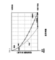
- FIG. 3 is a diagram illustrating an example of an estimated life prediction process.
- the horizontal axis of the figure shows the number of years of use, and the vertical axis shows the performance index.
- the upper limit of the vertical axis is the initial performance of the secondary battery 200a and corresponds to zero deterioration, and the lower limit of the vertical axis is the lower limit of performance of the secondary battery 200a and corresponds to the upper limit of deterioration.
- the actual deterioration curve shown by the solid line is the deterioration curve under the current battery usage conditions stored in the history storage unit 223 in step S103.
- the deterioration curve (prediction) shown by the dotted line predicts the progress of the secondary battery 200a after the present.
- the "deterioration curve of the root law” is experimentally known in which the degree of deterioration is directly proportional to the (1/2) power of the battery usage time. Therefore, by applying the deterioration curve of this route rule to the deterioration curve (solid line) under the current battery usage conditions, the deterioration curve (prediction) shown by the dotted line after the present can be obtained.
- the root rule is a general example of deterioration characteristics, it is preferable to use the deterioration rule obtained for the actual secondary battery 200a.
- Step S106 The shortage life calculation unit 232 obtains the shortage life by subtracting the estimated life from the target life. That is, in step S106, the (predicted) shortage life below the target life is obtained based on the estimated life.
- Step S107 The limit setting unit 233 determines the amount of reduction (that is, the amount of extension of battery life) until the next time of insufficient life.
- the expected shortage life may not be reduced to zero all at once, but the reduction in the shortage life may be distributed in a well-balanced manner during the period from the present to the target life, and the battery life may be extended stepwise.
- a predetermined ratio of the shortage life for example, 10% to 90%, preferably 25% to 75%, more preferably 40% to 60%
- the battery life is substantially matched with the target life by changing this predetermined ratio to nearly 100%.
- Step S108 The limit setting unit 233 limits the current battery usage conditions so as to extend the life of the insufficient life until the next time.
- the battery usage conditions to be restricted at least one or a combination of two or more of the following is selected.
- Charging voltage restrictions ⁇ Discharging current restrictions
- Charging current restrictions ⁇ Battery SOC restrictions
- Battery temperature restrictions Such restrictions on battery usage conditions preliminarily change the deterioration curve (prediction) of the secondary battery 200a. It can be set appropriately by trying it with a simulator or deterioration acceleration experiment.
- Step S109 There are a plurality of candidates for restricted battery usage conditions. Depending on which of these candidates is selected, the usage efficiency of the secondary battery 200a and the resulting deterioration in fuel consumption of the fuel engine 300a change. Therefore, the restriction setting unit 233 selects a candidate for minimizing (that is, optimizing) the deterioration of the fuel consumption plan of the fuel engine 300a from the candidates as the restricted battery usage condition. This selection operation is performed based on a rule created by a simulation of a fuel consumption plan in advance by a designer or the like.
- Step S110 The limit setting unit 233 resets the limited battery usage conditions to the battery control unit 210 as the battery usage conditions until the next reset time.
- the operation is returned to step S101 from step S110 shown in FIG. By this operation, the resetting that limits the battery usage conditions is repeated step by step.
- FIG. 4 is a diagram illustrating the extension of battery life.
- the period from the start of use to the target life is divided into a plurality of periods, and the time for resetting the battery usage conditions (white circle in FIG. 4) is provided.
- the shortage life is estimated and the battery usage conditions are reset to extend the battery life. This operation continues until the target life (replacement period) is reached and the battery replacement package 200b is replaced.
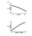
- [A] of FIG. 5 is a diagram showing a shortage life on the horizontal axis and an upper limit temperature on the vertical axis.
- the battery control unit 210 resets the battery operating conditions so that the larger the shortage life, the lower the upper limit temperature of the battery. That is, [A] in the figure shows an example of resetting the upper limit temperature due to insufficient life.
- [B] in FIG. 5 is a diagram showing (upper limit temperature-current temperature) on the horizontal axis and the current amount of the battery on the vertical axis.
- the battery control unit 210 reduces the charge / discharge current amount of the secondary battery 200a as shown in FIG. 5B, thereby reducing the charge / discharge current of the secondary battery 200a. Suppress the calorific value and prevent the current temperature from exceeding the upper limit temperature. That is, [B] in FIG. 5 shows an example of current control so as not to exceed the upper limit temperature.
- the battery usage conditions of the battery control unit 210 are reset in the direction of extending the battery life of the secondary battery 200a. By resetting the battery usage conditions, the life of the secondary battery 200a can be extended to the target life.
- the charging voltage is limited as a battery usage condition.
- the battery life is extended to the target life.
- the battery life is extended to the target life.
- the discharge current is limited as a battery usage condition.
- the discharge current is limited as a battery usage condition.
- the charging current is limited.
- the battery life is extended to the target life.
- the battery SOC States Of Charge
- the battery life is extended to the target life.
- Example 1 As a battery usage condition, for example, the battery temperature is limited. By limiting the battery temperature and delaying the deterioration of the secondary battery 200a, the battery life is extended to the target life.
- the one that minimizes the deterioration of the fuel consumption of the fuel engine 300a is selected. This selection operation makes it possible to minimize the deterioration of fuel efficiency.
- Example 1 the predicted deterioration curve of the secondary battery 200a (FIGS. 3 and 4) is compared with the actual deterioration curve (solid line curve of FIGS. 3 and 4) using the current battery usage conditions.
- the estimated life when the current battery usage conditions are used is obtained by the same arithmetic processing as applying the dotted curve).
- the calculation of the estimated life is estimated because other deterioration factors (for example, the speed and moving distance of the railroad vehicle 100, the weight load of the railroad car 100, the difference in speed change such as limited express or local train) are involved. Calculating life is complicated. However, by applying the predicted deterioration curve to the actual deterioration curve (solid line curves in FIGS. 3 and 4) that reflects these deterioration factors, it becomes possible to easily and accurately calculate the estimated life. ..
- the battery usage conditions are reset stepwise.
- the estimation accuracy of battery life becomes more accurate as the history of battery information is accumulated. Therefore, by repeating the estimation of the battery life and the resetting of the battery usage conditions step by step as the target life approaches, it becomes possible to accurately match the battery life with the target life.
- the battery operating conditions are reset stepwise, the battery operating conditions are reset from a relatively early stage. Therefore, it is possible to gradually start extending the battery life from a stage where the battery performance is relatively sufficient, and it is possible to prevent a situation in which the battery life is insufficient to reach the target life in the final phase.
- the battery life substantially coincides with the target life (replacement period of the battery replacement package 200b). Therefore, by replacing the battery replacement package 200b, the secondary battery 200a, the battery control unit 210, the estimation unit 220, and the limiting unit 230 can be replaced together, and the maintainability of battery replacement in the railway vehicle 100 is improved. To do.
- FIG. 6 is a diagram illustrating a configuration of a train formation.
- the same reference numerals are given to the same configurations as in the first embodiment, and duplicate description thereof will be omitted here.
- a plurality of connected vehicles 10 are connected in a row before and after the railway vehicle 100 via a mechanical coupler or the like.
- Each connected vehicle 10 is provided with a battery system 200 (battery control unit 210, secondary battery 200a, etc.) and a vehicle engine 300 similar to those of the railway vehicle 100.
- control system C and the power system E are connected between these vehicles via an electric coupler or a jumba coupler attached to the mechanical coupler.
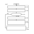
- FIG. 7 is a flow chart for explaining the accommodating operation of the insufficient current. Hereinafter, the operation will be described along with the step numbers shown in FIG. 7.
- Step S201 The battery control unit 210 acquires the upper limit of the discharge current that can be output from the secondary battery 200a based on the restrictions of the current battery usage conditions.
- Step S202 The battery control unit 210 of the railway vehicle 100 estimates the amount of discharge current required for the secondary battery 200a according to the operating state of the railway vehicle such as acceleration or deceleration of the vehicle speed.
- Step S203 The battery control unit 210 of the railroad vehicle 100 compares the required value of the discharge current obtained in S201 with the upper limit value obtained in step S202. When a discharge current larger than the upper limit value is required, the battery control unit 210 determines that the discharge current is insufficient in the railway vehicle 100, and shifts the operation to step S204. On the other hand, when the battery control unit 210 determines that the discharge current smaller than the upper limit value is sufficient, the railway vehicle 100 determines that the discharge current has a margin and shifts the operation to step S206. That is, in step S203, if "required discharge current> upper limit value" is YES, the process proceeds to S204, and if NO, the process proceeds to S206.
- Step S204 The battery control unit 210 of the railroad vehicle 100 transmits information to another group of connected vehicles 10 that the discharge current is insufficient only by the railroad vehicle 100 via the control system C.
- the connected vehicle 10 having the secondary battery 200a having a margin in the discharge current allocates the margin of the discharge current to the power system E. That is, in step S204, the current shortage is transmitted to another connected vehicle.
- Step S205 The battery control unit 210 of the railway vehicle 100 receives the discharge current from the secondary battery 200a of another connected vehicle 10 having a margin in the discharge current via the power system E to make up for the shortage of the discharge current. After this operation, the battery control unit 210 of the railway vehicle 100 returns to step S201 and repeats the operation.
- Step S206 When the battery control unit 210 of the railroad vehicle 100 receives information on the current shortage from another connected vehicle 10 via the control system C in a situation where the discharge current has a margin, the battery control unit 210 uses the margin of the discharge current as power. It is distributed to another connected vehicle 10 via the system E. After this operation, the battery control unit 210 of the railway vehicle 100 returns to step S201 and repeats the operation.
- the discharge current of the secondary battery 200a which is insufficient due to the restriction of the battery usage conditions, can be supplemented by receiving supply from the battery of another connected vehicle 10 having a margin of current.
- the present invention may be applied to a railroad vehicle that operates by power supply and battery power in an operation section that receives power from an overhead wire or a power supply rail, and operates only by battery power in an operation section that does not have a power supply means.
- the battery system 200 monitors the status of the secondary battery 200a, resets the battery usage conditions, controls the charge / discharge and temperature of the secondary battery 200a, controls the temperature, and accommodates the insufficient current.
- the invention is not limited to this. For example, a part or all of these functions may be shared by the control device of the railway vehicle 100.
- the insufficient current is interchanged between the vehicles, but the present invention is not limited to this.
- a plurality of secondary batteries 200a having different replacement times may be mounted in the railroad vehicle 100, and the battery control unit 210 may accommodate the insufficient current between the plurality of secondary batteries 200a.
- C control system, E ... power system, 10 ... connected vehicle, 100 ... railroad vehicle, 200 ... battery system, 200a ... secondary battery, 200b ... battery replacement package, 210 ... battery control unit, 220 ... estimation unit, 221 ... Battery information acquisition unit 222 ... Time information acquisition unit 223 ... History storage unit 224 ... Life prediction unit, 230 ... Limit unit 231 ... Target life setting unit 232 ... Insufficient life calculation unit 233 ... Limit setting unit, 300 ... Vehicle engine, 300a ... Fuel engine, 310 ... Generator, 330 ... Main converter, 350 ... Rail vehicle motor, 360 ... Power line
Landscapes
- Engineering & Computer Science (AREA)
- Manufacturing & Machinery (AREA)
- Chemical & Material Sciences (AREA)
- Chemical Kinetics & Catalysis (AREA)
- Electrochemistry (AREA)
- General Chemical & Material Sciences (AREA)
- Power Engineering (AREA)
- Life Sciences & Earth Sciences (AREA)
- Sustainable Development (AREA)
- Sustainable Energy (AREA)
- Transportation (AREA)
- Mechanical Engineering (AREA)
- Microelectronics & Electronic Packaging (AREA)
- Charge And Discharge Circuits For Batteries Or The Like (AREA)
- Secondary Cells (AREA)
- Electric Propulsion And Braking For Vehicles (AREA)
Abstract
本発明は、蓄電池の寿命を目標寿命まで確実に持たせることを目的とする。このため、代表的な本発明の電池システムの一つは、繰り返し使用可能な電池と、電池の寿命劣化に係る電池使用条件を制約することにより、電池の寿命を制御する電池制御部と、電池使用条件の制約によって得られる電池の推定寿命を算出する推定部と、算出された推定寿命に基づいて、電池の目標寿命に不足する不足寿命を求め、不足寿命を削減する方向に、電池制御部の電池使用条件を制限して再設定する制限部とを備える。
Description
本発明は、電池システム、鉄道車両および電池管理方法に関する。
エンジン発電機と二次電池とを相補的に使用することにより、低燃費、低排出ガス、低騒音を実現する、環境にやさしいハイブリッド鉄道車両が開発されている。
一般に、この種の二次電池は、充放電や温度などの使用環境によっては、劣化が速く進み、二次電池の寿命が短くなりやすい。
そこで、二次電池に設計上要求される電池寿命を確実に達成するため、二次電池を余分に搭載する、あるいは二次電池の使用環境を事前に制限して劣化を遅らせるなどの対策がとられている。
例えば、特許文献1には、二次電池の寿命が短い場合、劣化を遅らせるために、電流を制限する制御技術が開示される。
上述したハイブリッド鉄道車両では、保守性を考慮して、その他の電気部品の交換と一緒に、二次電池の交換が行われる。しかしながら、二次電池の電池寿命が設計時の想定ギリギリで電池システムを設計した場合、目標とする期間(以下「目標寿命」)よりも前に電池寿命に到達してしまう可能性がある。
そこで、本発明は、電池寿命を目標寿命に近づける技術を提供することを目的とする。
上記課題を解決するために、代表的な本発明の電池システムの一つは、電池使用条件により電池の寿命を制御する電池制御部と、電池の推定寿命を算出する推定部と、算出された推定寿命が電池の目標寿命を下回る場合に、電池の寿命を延ばして目標寿命の不足分(以下「不足寿命」)を削減する方向に、電池制御部の電池使用条件を再設定する制限部とを備える。
本発明によれば、電池寿命を目標寿命に近づけることが可能になる。
上記した以外の課題、構成および効果は、以下の実施形態の説明により明らかにされる。
以下、図を参照して本発明を実施するための形態について説明する。
<実施例1の構成>
図1は、鉄道車両100の構成を示す図である。
同図において、鉄道車両100は、電池システム200、車両機関300とを備えて構成される。
図1は、鉄道車両100の構成を示す図である。
同図において、鉄道車両100は、電池システム200、車両機関300とを備えて構成される。
電池システム200は、一体交換可能な電池交換パッケージ200bの中に、二次電池200a(例えば、リチウムイオン二次電池セル)、電池制御部210、推定部220、および制限部230を内蔵して構成される。
例えば、ASIC、FPGA、またはCPUなどの処理装置(メモリを含む)をソフトウェアにより稼働させることにより、これらの電池制御部210、推定部220、および制限部230の機能を実現してもよい。
二次電池200aは、充放電により繰り返し使用可能な電池である。この二次電池200aには、温度管理するための機構(ペルチェ素子、ヒーター、冷却ファン、空冷、液冷など)や、電気的特性を測定するための電流センサ、電圧センサ、温度センサなどが、必要に応じて設けられる。
電池制御部210は、この二次電池200aの充放電制御や使用温度などの電池の寿命劣化に係る電池使用条件を制約するように初期設定され、二次電池200aの寿命を目標寿命から延長する方向に制御する。以下、本開示において『制約』とは、電池の寿命劣化に係る電池使用条件について上下限などの制限を設定して電池を使用することをいう。
推定部220は、二次電池200aから電気的特性などの電池情報を取得する電池情報取得部221と、二次電池200aの使用に係る時刻情報を取得する時刻情報取得部222と、電池情報や時刻情報や電池使用条件の履歴を記憶する履歴記憶部223と、履歴記憶部223の履歴に基づいて二次電池200aの推定寿命を求める寿命予測部224とを備える。
制限部230は、電池交換パッケージ200bの交換期間である目標寿命が設定される目標寿命設定部231と、二次電池200aに予測される不足寿命を推定寿命と目標寿命との差に基づいて求める不足寿命演算部232と、不足寿命を削減する方向に電池制御部210の電池使用条件を制限して再設定する制限設定部233とを備える。
車両機関300は、ディーゼルエンジンなどの燃料機関300a(ディーゼルエンジンなど)と、燃料機関300aの動力により三相電力を発電する発電機310と、主変換装置330(コンバータ・インバータ)と、鉄道車両100の推進力などを発生させる鉄道車両モータ350と、鉄道車両100内の電源ライン360(ドア開閉装置、エアコンなどの電源)とを備える。
主変換装置330は、発電機310で発電される三相電力を直流電力に変換するコンバータ機能と、変換された直流電力を電池制御部210を介して二次電池200aに充電する充電機能と、二次電池200aの直流電力を電池制御部210を介して三相電力に変換するインバータ機能と、鉄道車両モータ350および電源ライン360に供給する各種電力の供給元を、発電機310側と二次電池200a側との間で相補的に切り替えるハイブリッド機能とを備える。
<電池使用条件の再設定>
図2は、電池使用条件の再設定を説明する流れ図である。
同図に示すステップ番号に沿って、実施例1の動作を説明する。
図2は、電池使用条件の再設定を説明する流れ図である。
同図に示すステップ番号に沿って、実施例1の動作を説明する。
ステップS101: 電池情報取得部221は、二次電池200aまたはその周辺に取り付けられた電流センサ、電圧センサ、温度センサなどから電気的特性(電流値I、電圧値V、温度T)を取得し、履歴記憶部223へ出力する。履歴記憶部223は、「電気的特性」、「時刻情報」、「過去の電池使用条件」などの情報をセットにして電池情報として履歴記憶する。つまり、ステップS101では、定期的に電池情報を取得して履歴に保存する。
ステップS102: 寿命予測部224は、内部に電池劣化データベースを保持する。寿命予測部224は、履歴記憶部223に保存された電池情報の履歴を、電池劣化データベースに照合することにより、二次電池200aの劣化度を求める。つまり、ステップS102では、電池情報(の履歴)から劣化度を求める。
ステップS103: 寿命予測部224は、劣化度の進み具合(劣化度情報)を、時刻情報と共に履歴記憶部223に履歴として保存する。つまり、ステップ103では、劣化度を保存する。
ステップS104: 推定部220は、電池の劣化度の進み具合や、予め定められた期間に基づいて、電池使用条件の再設定時期か否かを判定する。
電池使用条件の再設定時期でない場合、推定部220は、ステップS101に動作を戻す。一方、電池使用条件の再設定時期と判定された場合、推定部220は、ステップS105に動作を移行する。
この再設定時期は、一定間隔おきや、予め定められた不等な時間間隔おきや、不定期に定めてもよい。また、劣化度が一定量や所定量進むたびに再設定時期としてもよい。
ステップS105: 寿命予測部224は、現在の電池使用条件による劣化度の進み具合に基づいて、推定寿命を予測する。
図3は、推定寿命の予測処理の一例を説明する図である。
同図の横軸は使用年数を示し、縦軸は性能指標を示す。なお、縦軸の上限は二次電池200aの初期性能であって劣化度ゼロに相当し、縦軸の下限は二次電池200aの性能下限値であって劣化度の上限に相当する。
同図の横軸は使用年数を示し、縦軸は性能指標を示す。なお、縦軸の上限は二次電池200aの初期性能であって劣化度ゼロに相当し、縦軸の下限は二次電池200aの性能下限値であって劣化度の上限に相当する。
同図において、実線で示す実績の劣化カーブは、ステップS103で履歴記憶部223に格納された現在の電池使用条件のもとにおける劣化カーブである。一方、点線で示す劣化カーブ(予測)は、現在以降の二次電池200aの進み具合を予測するものである。
一般に、リチウムイオン二次電池などでは、電池使用時間の(1/2)乗に劣化度が正比例するという「ルート則の劣化カーブ」が実験的に知られている。そこで、現在の電池使用条件のもとにおける劣化カーブ(実線)に、このルート則の劣化カーブを当てはめることにより、現在以降における点線で示す劣化カーブ(予測)を得ることができる。
この劣化カーブ(予測)が、劣化度の上限(図3の性能下限値)に到達した使用年数が、推定寿命となる。
なお、ルート則は劣化特性の一般例であるため、現実の二次電池200aについて求めた劣化則を使用することが好ましい。
ステップS106: 不足寿命演算部232は、目標寿命から推定寿命を減算することにより、不足寿命を求める。つまり、ステップS106では、推定寿命に基づいて、目標寿命を下回る(予測)不足寿命を求める。
ステップS107: 制限設定部233は、不足寿命の次回までの削減分(つまり電池寿命の延長分)を決定する。このとき、予測される不足寿命を一度にゼロにせず、現在から目標寿命までの期間に不足寿命の削減分をバランスよく配分し、電池寿命を段階的に延長してもよい。例えば、不足寿命の所定割合(例えば10%~90%、好ましくは25%~75%、さらに好ましくは40%~60%)を、不足寿命の次回までの削減分(電池寿命の延長分)として決定する。また、目標寿命を迎えるまでの最終期間においては、この所定割合を100%近くまで変化させることにより電池寿命を目標寿命に略一致させる。
ステップS108: 制限設定部233は、不足寿命の次回までの延命分を実現するように、現在の電池使用条件を制限する。ここで制限する電池使用条件としては、次の少なくとも1つ、または2つ以上の組合せが選択される。
・充電電圧の制約
・放電電流の制約
・充電電流の制約
・電池SOCの制約
・電池温度の制約
このような電池使用条件の制限は、劣化カーブ(予測)の変化を事前に二次電池200aのシミュレータや劣化加速実験で試行しておくことによって適切に設定できる。
・充電電圧の制約
・放電電流の制約
・充電電流の制約
・電池SOCの制約
・電池温度の制約
このような電池使用条件の制限は、劣化カーブ(予測)の変化を事前に二次電池200aのシミュレータや劣化加速実験で試行しておくことによって適切に設定できる。
ステップS109: 制限した電池使用条件の候補は、複数通り存在する。この候補のどれを選択するかにより、二次電池200aの使用効率と、それに伴う燃料機関300aの燃費悪化が変化する。そこで、制限設定部233は、候補の中から、燃料機関300aの燃費計画の悪化を最小化(つまり最適化)する候補を、制限した電池使用条件として選択する。この選択動作は、設計者などによる事前の燃費計画のシミュレーションにより作成されたルールに基づいて行われる。
ステップS110: 制限設定部233は、制限した電池使用条件を、次回の再設定時期までの電池使用条件として、電池制御部210に再設定する。
この電池使用条件の再設定を完了すると、図2に示すステップS110から動作をステップS101に戻す。この動作により、電池使用条件を制限する再設定を段階的に繰り返す。
この電池使用条件の再設定を完了すると、図2に示すステップS110から動作をステップS101に戻す。この動作により、電池使用条件を制限する再設定を段階的に繰り返す。
図4は、電池寿命の延命を説明する図である。
同図では、使用開始時から目標寿命までの期間が複数区分され、電池使用条件の再設定時期(図4中の白丸)が設けられる。この再設定時期ごとに、不足寿命の推定と、電池使用条件の再設定とが行われ、電池寿命の延命が行われる。
この動作は、目標寿命(交換期間)に達して、電池交換パッケージ200bが交換されるまで継続する。
同図では、使用開始時から目標寿命までの期間が複数区分され、電池使用条件の再設定時期(図4中の白丸)が設けられる。この再設定時期ごとに、不足寿命の推定と、電池使用条件の再設定とが行われ、電池寿命の延命が行われる。
この動作は、目標寿命(交換期間)に達して、電池交換パッケージ200bが交換されるまで継続する。
<電池の上限温度を制約する動作>
次に、二次電池200aが冷却機構(ペルチェ素子、冷却ファン、液冷など)を有しない場合に、二次電池200aの上限温度を制約する動作について説明する。
次に、二次電池200aが冷却機構(ペルチェ素子、冷却ファン、液冷など)を有しない場合に、二次電池200aの上限温度を制約する動作について説明する。
図5の[A]は、横軸に不足寿命を示し、縦軸に上限温度を示す図である。
電池制御部210は、この図5の[A]に示すように、不足寿命が大きいほど、電池の上限温度を低くなるように電池使用条件の再設定を行う。つまり、図の[A]は、不足寿命による上限温度の再設定の例を示したものである。
電池制御部210は、この図5の[A]に示すように、不足寿命が大きいほど、電池の上限温度を低くなるように電池使用条件の再設定を行う。つまり、図の[A]は、不足寿命による上限温度の再設定の例を示したものである。
図5の[B]は、横軸に(上限温度-現在温度)を示し、縦軸に電池の電流量を示す図である。
電池制御部210は、二次電池200aの現在温度が上限温度に迫ると、図5の[B]に示すように、二次電池200aの充放電の電流量を下げることにより二次電池200aの発熱量を抑制し、現在温度が上限温度を超えないようにする。つまり、図5の[B]は、上限温度を超えないための電流制御の例を示したものである。
電池制御部210は、二次電池200aの現在温度が上限温度に迫ると、図5の[B]に示すように、二次電池200aの充放電の電流量を下げることにより二次電池200aの発熱量を抑制し、現在温度が上限温度を超えないようにする。つまり、図5の[B]は、上限温度を超えないための電流制御の例を示したものである。
このような電池制御部210の動作により、二次電池200aの上限温度を制約することが可能になる。
<実施例1の効果>
以下、実施例1の効果について説明する。
以下、実施例1の効果について説明する。
(1)実施例1では、二次電池200aの電池寿命を延命する方向に、電池制御部210の電池使用条件を再設定する。この電池使用条件の再設定により、二次電池200aの寿命を目標寿命まで持たせることができる。
(2)実施例1では、電池使用条件として、例えば、充電電圧を制限する。この充電電圧の上限を低くして二次電池200aの劣化を遅らせることにより、電池寿命は目標寿命まで延長される。あるいは、充電電圧の下限を高くして二次電池200aの劣化を遅らせることにより、電池寿命は目標寿命まで延長される。
(3)実施例1では、電池使用条件として、例えば、放電電流を制限する。この放電電流を制限して二次電池200aの劣化を遅らせることにより、電池寿命は目標寿命まで延長される。
(4)実施例1では、電池使用条件として、例えば、充電電流を制限する。この充電電流を制限して二次電池200aの劣化を遅らせることにより、電池寿命は目標寿命まで延長される。
(5)実施例1では、電池使用条件として、例えば、電池SOC(States Of Charge:充電状態)を制限する。この電池SOCを低くして二次電池200aの劣化を遅らせることにより、電池寿命は目標寿命まで延長される。
(6)実施例1では、電池使用条件として、例えば、電池温度を制限する。この電池温度を制限して二次電池200aの劣化を遅らせることにより、電池寿命は目標寿命まで延長される。
(7)実施例1では、制限する電池使用条件やその組合せの候補が複数ある場合に、燃料機関300aの燃費悪化が最小化するものを選択する。この選択動作によって燃費悪化を最小限に抑えることが可能になる。
(8)実施例1では、現在の電池使用条件を使用した実績の劣化カーブ(図3、図4の実線カーブ)に対して、二次電池200aの予測の劣化カーブ(図3、図4の点線カーブ)を当てはめると同等の演算処理により、現在の電池使用条件を使用した場合の推定寿命を求める。
一般に、推定寿命の算出には、他の劣化要因(例えば、鉄道車両100の速度や移動距離や、鉄道車両100の重量負荷、特急や各駅停車といった速度変化の違いなど)が関係するため、推定寿命の算出は複雑になる。しかしながら、これら劣化要因が反映された、実績の劣化カーブ(図3、図4の実線カーブ)に予測の劣化カーブを当てはめることにより、推定寿命の算出を簡易にかつ正確に行うことが可能になる。
(9)実施例1では、図4に示すように、電池使用条件の再設定を段階的に行う。電池寿命の推定精度は、電池情報の履歴が蓄積されるほど正確になる。そのため、目標寿命に近づくに従って電池寿命の推定と電池使用条件の再設定を段階的に繰り返すことより、電池寿命を目標寿命に正確に略一致させることが可能になる。
(10)実施例1では、電池使用条件の再設定を段階的に行うため、比較的に早い段階から電池使用条件の再設定を開始する。そのため、電池性能に比較的余裕がある段階から電池寿命の延命化を徐々に開始することが可能になり、最終局面において電池寿命が目標寿命に足りないなどの事態を防止することができる。
(11)実施例1では、上述したように、電池寿命が目標寿命(電池交換パッケージ200bの交換期間)に略一致する。そのため、電池交換パッケージ200bの交換により、二次電池200a、電池制御部210、推定部220、および制限部230を一緒に交換することが可能になり、鉄道車両100における電池交換のメンテナンス性が向上する。
次に、実施例2として、列車編成された車両の間で、電池使用条件の制約に伴う電流不足を相互に補う動作を説明する。
<実施例2の構成>
図6は、列車編成の構成を説明する図である。
なお、図6において、実施例1と同じ構成については同一の参照符号を付与し、ここでの重複説明を省略する。
図6は、列車編成の構成を説明する図である。
なお、図6において、実施例1と同じ構成については同一の参照符号を付与し、ここでの重複説明を省略する。
列車編成として、鉄道車両100の前後には、機械連結器などを介して複数の連結車両10が一列に連結される。
個々の連結車両10には、鉄道車両100と同様の電池システム200(電池制御部210,二次電池200aなど)および車両機関300がそれぞれ設けられる。
個々の連結車両10には、鉄道車両100と同様の電池システム200(電池制御部210,二次電池200aなど)および車両機関300がそれぞれ設けられる。
これら車両は、電池システム200の交換時期が互いに異なるため、電池使用条件の制約も車両ごとに異なるものとなる。
これら車両の間では、機械連結器に併設される電気連結器やジャンバ連結器などを介して、制御系統Cおよび電力系統Eが接続される。
<実施例2の動作>
図7は、不足電流の融通動作を説明する流れ図である。
以下、図7に示すステップ番号に沿って、動作を説明する。
図7は、不足電流の融通動作を説明する流れ図である。
以下、図7に示すステップ番号に沿って、動作を説明する。
ステップS201: 電池制御部210は、現在の電池使用条件の制約に基づいて、二次電池200aから出力可能な放電電流の上限値を取得する。
ステップS202: 鉄道車両100の電池制御部210は、車両速度の加速や減速などの鉄道車両の運行状態に応じて、二次電池200aに必要とされる放電電流の量を推定する。
ステップS203: 鉄道車両100の電池制御部210は、S201で求めた放電電流の必要な値と、ステップS202で求めた上限値とを比較する。電池制御部210は、上限値よりも大きな放電電流が必要な場合、鉄道車両100では放電電流が不足すると判断してステップS204に動作を移行する。一方、電池制御部210は、上限値よりも小さな放電電流で足りる場合、鉄道車両100は放電電流に余裕があると判断してステップS206に動作を移行する。つまり、ステップS203では、「必要な放電電流>上限値」がYESの場合はS204に移行し、NOの場合には、S206に移行することなる。
ステップS204: 鉄道車両100の電池制御部210は、鉄道車両100だけでは放電電流が不足する旨を別の連結車両10の群に制御系統Cを介して情報伝達する。別の連結車両10の内、放電電流に余裕がある二次電池200aを有する連結車両10は、電力系統Eに対して放電電流の余裕分を配分する。つまり、ステップS204では、電流不足を別の連結車両に情報伝達する。
ステップS205: 鉄道車両100の電池制御部210は、放電電流に余裕がある別の連結車両10の二次電池200aから放電電流の供給を電力系統Eを介して受け、放電電流の不足を補う。この動作の後に、鉄道車両100の電池制御部210は、ステップS201に戻って動作を繰り返す。
ステップS206: 鉄道車両100の電池制御部210は、放電電流に余裕がある状況で、制御系統Cを介して別の連結車両10から電流不足の情報伝達を受けると、放電電流の余裕分を電力系統Eを介して別の連結車両10に配分する。この動作の後に、鉄道車両100の電池制御部210は、ステップS201に戻って動作を繰り返す。
<実施例2の効果>
上述した一連の動作により、実施例2では、実施例1の効果に加えて次の効果を得ることができる。
上述した一連の動作により、実施例2では、実施例1の効果に加えて次の効果を得ることができる。
(1)実施例2では、電池使用条件の制約により不足する二次電池200aの放電電流を、電流に余裕がある別の連結車両10の電池から供給を受けて補うことができる。
(2)実施例2では、放電電流が不足しても別の連結車両10から補うことができるため、燃料機関300aによる一時的な発電を頻繁に行う必要がなくなり、燃料の消費量を下げることができる。
(3)実施例1で説明した車両別の電池使用条件の再設定と、実施例2で説明した車両間の一時的な放電電流の融通とは同時に行われる。そのため、車両別に二次電池200aの寿命管理を行いつつ、列車編成の全体において車両ごとの電流不足を解消するというバランスのよい電池管理が実現する。
<補足事項>
なお、上述した実施形態では、燃料機関300aを搭載したハイブリッド鉄道車両への応用について説明した。しかし、本発明の適用分野はこれに限定されない。
なお、上述した実施形態では、燃料機関300aを搭載したハイブリッド鉄道車両への応用について説明した。しかし、本発明の適用分野はこれに限定されない。
例えば、架線や給電レールなどから給電を受ける運行区間においては給電力および電池電力によって運行し、給電手段のない運行区間においては電池電力のみで運行する鉄道車両に本発明を適用してもよい。
なお、実施形態では、電池システム200において、二次電池200aの状態監視、電池使用条件の再設定、二次電池200aの充放電制御や温度制御、不足電流の融通などを行っているが、本発明はこれに限定されない。例えば、これらの機能の一部または全部を鉄道車両100の制御装置で分担してもよい。
また、実施形態の実施例2では、車両と車両の間において不足電流の融通を行っているが、本発明はこれに限定されない。例えば、鉄道車両100内に交換時期の異なる複数の二次電池200aを搭載し、電池制御部210によって複数の二次電池200aの間で不足電流の融通を行ってもよい。
上記の通り、種々の実施の形態について説明したが、本発明はこれらの内容に限定されるものではない。本発明の技術的思想の範囲内で考えられるその他の態様も本発明の範囲内に含まれる。
例えば、上記した実施例は本発明を分かりやすく説明するために詳細に説明したものであり、必ずしも説明した全ての構成を備えるものに限定されるものではない。
また、ある実施例の構成の一部を他の実施例の構成に置き換えることが可能であり、また、ある実施例の構成に他の実施例の構成を加えることも可能である。
さらに、各実施例の構成の一部について、他の構成の追加・削除・置換をすることが可能である。
例えば、上記した実施例は本発明を分かりやすく説明するために詳細に説明したものであり、必ずしも説明した全ての構成を備えるものに限定されるものではない。
また、ある実施例の構成の一部を他の実施例の構成に置き換えることが可能であり、また、ある実施例の構成に他の実施例の構成を加えることも可能である。
さらに、各実施例の構成の一部について、他の構成の追加・削除・置換をすることが可能である。
C…制御系統、E…電力系統、10…連結車両、100…鉄道車両、200…電池システム、200a…二次電池、200b…電池交換パッケージ、210…電池制御部、220…推定部、221…電池情報取得部、222…時刻情報取得部、223…履歴記憶部、224…寿命予測部、230…制限部、231…目標寿命設定部、232…不足寿命演算部、233…制限設定部、300…車両機関、300a…燃料機関、310…発電機、330…主変換装置、350…鉄道車両モータ、360…電源ライン
Claims (11)
- 繰り返し使用可能な電池を備えた電池システムであって、
前記電池の寿命劣化に係る電池使用条件を制約して設定することにより、前記電池の寿命を制御する電池制御部と、
前記電池使用条件の制約によって得られる前記電池の推定寿命を算出する推定部と、
算出された前記推定寿命が前記電池の目標寿命を下回る場合に、前記電池の寿命を延ばして前記目標寿命の不足分(以下「不足寿命」)を削減する方向に、前記電池制御部の前記電池使用条件を制限して再設定する制限部と、
を備えたことを特徴とする電池システム。 - 請求項1に記載の電池システムにおいて、
前記電池制御部は、
前記電池使用条件の制約により不足する前記電池の電流分を、電流に余裕がある別の電池から供給を受けることにより、前記電流分の不足を補う
ことを特徴とする電池システム。 - 請求項2に記載の電池システムにおいて、
前記電池は、
鉄道車両に使用される鉄道車両用電池であり、
前記電池制御部は、
前記電池使用条件の制約により不足する前記電池の電流分を、電流に余裕がある別の連結車両の電池から供給を受けることにより、前記電流分の不足を補う
ことを特徴とする電池システム。 - 請求項1~3のいずれか1項に記載の電池システムにおいて、
前記制限部は、
前記電池使用条件を制限する再設定を段階的に行い、前記電池の前記不足寿命を段階的になくす
ことを特徴とする電池システム。 - 請求項1~4のいずれか1項に記載の電池システムにおいて、
前記制限部において制限する再設定を行う前記電池使用条件は、
充電電圧の制約、放電電流の制約、充電電流の制約、電池SOC(States Of Charge:充電状態)の制約、および電池温度の制約からなるグループの少なくとも一つである
ことを特徴とする電池システム。 - 請求項1~5のいずれか1項に記載の電池システムにおいて、
前記制限部は、
前記不足寿命に応じて、前記電池の上限温度の制約を決定し、
前記電池制御部は、
前記電池の現在温度をモニタリングし、前記上限温度と前記現在温度との差異に応じて、前記電池の充放電の電流を制御する
ことを特徴とする電池システム。 - 請求項1~6のいずれか1項に記載の電池システムにおいて、
前記電池に対して、前記電池制御部、前記推定部、前記制限部は一体に構成され、
前記電池の寿命交換に際して、前記電池システムを一体に交換可能とする
ことを特徴とする電池システム。 - 請求項1~7のいずれか1項に記載の電池システムと、
前記電池システムの前記電池を電源の少なくとも一つとして使用する車両部と、
を備えたことを特徴とする鉄道車両。 - 繰り返し使用可能な電池を使用する電池管理方法であって、
前記電池の寿命劣化に係る電池使用条件を制約して設定することにより、前記電池の寿命を制御する電池制御ステップと、
前記電池使用条件の制約によって得られる前記電池の推定寿命を算出する推定ステップと、
算出された前記推定寿命が前記電池の目標寿命を下回る場合に、前記電池の寿命を延ばして前記目標寿命の不足分(以下「不足寿命」)を削減する方向に、前記電池制御ステップの前記電池使用条件を制限して再設定する制限ステップと、
を備えたことを特徴とする電池管理方法。 - 請求項9に記載の電池管理方法において、
前記電池制御ステップは、
前記電池使用条件の制約により不足する前記電池の電流分を、電流に余裕がある別の電池から供給を受けることにより、前記電流分の不足を補う
ことを特徴とする電池管理方法。 - 請求項9~10のいずれか1項に記載の電池管理方法において、
前記電池は、
鉄道車両に使用される鉄道車両用電池であり、
前記電池制御ステップは、
前記電池使用条件の制約により不足する前記電池の電流分を、電流に余裕がある別の連結車両の電池から供給を受けることにより、前記電流分の不足を補う
ことを特徴とする電池管理方法。
Priority Applications (1)
| Application Number | Priority Date | Filing Date | Title |
|---|---|---|---|
| EP20787625.1A EP3955409A4 (en) | 2019-04-12 | 2020-04-03 | BATTERY SYSTEM, RAIL CAR AND BATTERY MANAGEMENT PROCEDURES |
Applications Claiming Priority (2)
| Application Number | Priority Date | Filing Date | Title |
|---|---|---|---|
| JP2019076064A JP7254597B2 (ja) | 2019-04-12 | 2019-04-12 | 電池システム、鉄道車両および電池管理方法 |
| JP2019-076064 | 2019-04-12 |
Publications (1)
| Publication Number | Publication Date |
|---|---|
| WO2020209200A1 true WO2020209200A1 (ja) | 2020-10-15 |
Family
ID=72751538
Family Applications (1)
| Application Number | Title | Priority Date | Filing Date |
|---|---|---|---|
| PCT/JP2020/015341 Ceased WO2020209200A1 (ja) | 2019-04-12 | 2020-04-03 | 電池システム、鉄道車両および電池管理方法 |
Country Status (3)
| Country | Link |
|---|---|
| EP (1) | EP3955409A4 (ja) |
| JP (1) | JP7254597B2 (ja) |
| WO (1) | WO2020209200A1 (ja) |
Cited By (1)
| Publication number | Priority date | Publication date | Assignee | Title |
|---|---|---|---|---|
| WO2026069747A1 (ja) * | 2024-09-25 | 2026-04-02 | 株式会社日立ハイテク | 二次電池の劣化状態予測方法、および、電池情報管理システム |
Families Citing this family (6)
| Publication number | Priority date | Publication date | Assignee | Title |
|---|---|---|---|---|
| JP2023076346A (ja) * | 2021-11-22 | 2023-06-01 | 株式会社デンソーテン | 電源装置および予測方法 |
| JP2024116747A (ja) * | 2023-02-16 | 2024-08-28 | 日立グローバルライフソリューションズ株式会社 | 電気掃除機 |
| JP7694605B2 (ja) * | 2023-05-22 | 2025-06-18 | トヨタ自動車株式会社 | 加熱システムの制御装置、それを備える車両、および、熱媒体の管理方法 |
| JP2025125417A (ja) * | 2024-02-15 | 2025-08-27 | エナジーウィズ株式会社 | 業務管理方法、プログラム及び業務管理システム |
| CN121970228A (zh) * | 2024-08-27 | 2026-05-01 | 日本汽车能源株式会社 | 电池控制装置以及电池控制方法 |
| KR102854433B1 (ko) * | 2024-08-30 | 2025-09-03 | 주식회사 중앙첨단소재 | 철도차량용 차축발전 및 전력운용시스템 |
Citations (7)
| Publication number | Priority date | Publication date | Assignee | Title |
|---|---|---|---|---|
| JP2007259612A (ja) * | 2006-03-24 | 2007-10-04 | Hitachi Ltd | 電源制御装置 |
| DE102009023340A1 (de) * | 2009-05-29 | 2011-02-03 | Daimler Ag | Verfahren zum Betreiben einer elektrischen Fahrzeugantriebseinheit |
| WO2011118294A1 (ja) * | 2010-03-23 | 2011-09-29 | 日本電気株式会社 | リチウムイオン二次電池の充放電方法及び充放電システム |
| WO2012128285A1 (ja) * | 2011-03-23 | 2012-09-27 | 三菱重工業株式会社 | 電池システム |
| JP2014078358A (ja) * | 2012-10-09 | 2014-05-01 | Mitsubishi Motors Corp | 電力制御装置 |
| JP2014079066A (ja) * | 2012-10-09 | 2014-05-01 | Mitsubishi Motors Corp | 電力制御装置 |
| JP2016163532A (ja) | 2015-03-05 | 2016-09-05 | 日立オートモティブシステムズ株式会社 | 電池管理装置、電池システムおよびハイブリッド車両制御システム |
Family Cites Families (6)
| Publication number | Priority date | Publication date | Assignee | Title |
|---|---|---|---|---|
| JP5679738B2 (ja) * | 2010-08-26 | 2015-03-04 | 株式会社日立製作所 | 電池制御装置及びこの電池制御装置を搭載した車両システム |
| US20130294479A1 (en) * | 2011-01-24 | 2013-11-07 | Toyota Jidosha Kabushiki Kaisha | Electric storage system |
| US9263912B2 (en) * | 2013-02-05 | 2016-02-16 | Dell Products, L.P. | Mitigating premature wear out of a rechargeable battery |
| US9331503B2 (en) * | 2014-03-06 | 2016-05-03 | Nissan North America, Inc. | Systems and methods of controlling battery deterioration by controlling battery state-of-health during power exchange |
| JP6441188B2 (ja) * | 2015-09-01 | 2018-12-19 | 日立オートモティブシステムズ株式会社 | 電池管理装置、電池システムおよびハイブリッド車両制御システム |
| EP3424771A1 (en) * | 2017-07-03 | 2019-01-09 | Ningbo Geely Automobile Research & Development Co. Ltd. | Method and electronic device for managing a power limit |
-
2019
- 2019-04-12 JP JP2019076064A patent/JP7254597B2/ja active Active
-
2020
- 2020-04-03 WO PCT/JP2020/015341 patent/WO2020209200A1/ja not_active Ceased
- 2020-04-03 EP EP20787625.1A patent/EP3955409A4/en active Pending
Patent Citations (7)
| Publication number | Priority date | Publication date | Assignee | Title |
|---|---|---|---|---|
| JP2007259612A (ja) * | 2006-03-24 | 2007-10-04 | Hitachi Ltd | 電源制御装置 |
| DE102009023340A1 (de) * | 2009-05-29 | 2011-02-03 | Daimler Ag | Verfahren zum Betreiben einer elektrischen Fahrzeugantriebseinheit |
| WO2011118294A1 (ja) * | 2010-03-23 | 2011-09-29 | 日本電気株式会社 | リチウムイオン二次電池の充放電方法及び充放電システム |
| WO2012128285A1 (ja) * | 2011-03-23 | 2012-09-27 | 三菱重工業株式会社 | 電池システム |
| JP2014078358A (ja) * | 2012-10-09 | 2014-05-01 | Mitsubishi Motors Corp | 電力制御装置 |
| JP2014079066A (ja) * | 2012-10-09 | 2014-05-01 | Mitsubishi Motors Corp | 電力制御装置 |
| JP2016163532A (ja) | 2015-03-05 | 2016-09-05 | 日立オートモティブシステムズ株式会社 | 電池管理装置、電池システムおよびハイブリッド車両制御システム |
Non-Patent Citations (1)
| Title |
|---|
| See also references of EP3955409A4 |
Cited By (1)
| Publication number | Priority date | Publication date | Assignee | Title |
|---|---|---|---|---|
| WO2026069747A1 (ja) * | 2024-09-25 | 2026-04-02 | 株式会社日立ハイテク | 二次電池の劣化状態予測方法、および、電池情報管理システム |
Also Published As
| Publication number | Publication date |
|---|---|
| EP3955409A4 (en) | 2023-01-25 |
| JP7254597B2 (ja) | 2023-04-10 |
| EP3955409A1 (en) | 2022-02-16 |
| JP2020174490A (ja) | 2020-10-22 |
Similar Documents
| Publication | Publication Date | Title |
|---|---|---|
| WO2020209200A1 (ja) | 電池システム、鉄道車両および電池管理方法 | |
| US8587260B2 (en) | Method and system for control of a vehicle energy storage device | |
| US8063609B2 (en) | Method and system for extending life of a vehicle energy storage device | |
| KR102385058B1 (ko) | 에너지 스토리지 시스템을 가지는 차량 추진 시스템 및 그 동작을 제어하는 최적화 방법 | |
| CN104704703B (zh) | 具有耦合存储设备的机动车用能量管理系统 | |
| CN109466375B (zh) | 增程器控制方法及设备、计算机可读存储介质、车辆 | |
| US20100179714A1 (en) | Vehicle drive power generation control apparatus | |
| KR102881957B1 (ko) | 하이브리드 차량의 동력 분배 장치 및 방법 | |
| JP2016047005A (ja) | エネルギー貯蔵システムを有する車両推進システムおよびその動作を制御する最適化された方法 | |
| JP2023532481A (ja) | 電気駆動システムを作動させるための方法 | |
| ES2940508T3 (es) | Vehículo y procedimiento para su funcionamiento | |
| US12447868B2 (en) | Method for controlling a power assembly | |
| KR102656116B1 (ko) | 멀티 세트의 하이브리드 전원에 의해 구동되는 전기 트램의 에너지 관리 시스템 | |
| KR20160038010A (ko) | 발전 제어 장치 및 발전 제어 방법 | |
| GB2601224A (en) | Vehicle control device and vehicle control method | |
| JP2020174489A (ja) | 電池システム、鉄道車両および電池管理方法 | |
| US20200039355A1 (en) | Switching control device and switching control method | |
| JP2026010477A (ja) | 制御サーバ、車両及び制御サーバの制御方法 | |
| AU2014202139B2 (en) | Method and system for control of a vehicle energy storage device |
Legal Events
| Date | Code | Title | Description |
|---|---|---|---|
| 121 | Ep: the epo has been informed by wipo that ep was designated in this application |
Ref document number: 20787625 Country of ref document: EP Kind code of ref document: A1 |
|
| NENP | Non-entry into the national phase |
Ref country code: DE |
|
| ENP | Entry into the national phase |
Ref document number: 2020787625 Country of ref document: EP Effective date: 20211112 |