WO2020213421A1 - トラクタの走行伝動装置 - Google Patents
トラクタの走行伝動装置 Download PDFInfo
- Publication number
- WO2020213421A1 WO2020213421A1 PCT/JP2020/015218 JP2020015218W WO2020213421A1 WO 2020213421 A1 WO2020213421 A1 WO 2020213421A1 JP 2020015218 W JP2020015218 W JP 2020015218W WO 2020213421 A1 WO2020213421 A1 WO 2020213421A1
- Authority
- WO
- WIPO (PCT)
- Prior art keywords
- front wheel
- clutch
- transmission shaft
- speed
- power
- Prior art date
- Legal status (The legal status is an assumption and is not a legal conclusion. Google has not performed a legal analysis and makes no representation as to the accuracy of the status listed.)
- Ceased
Links
Images





Classifications
-
- B—PERFORMING OPERATIONS; TRANSPORTING
- B60—VEHICLES IN GENERAL
- B60K—ARRANGEMENT OR MOUNTING OF PROPULSION UNITS OR OF TRANSMISSIONS IN VEHICLES; ARRANGEMENT OR MOUNTING OF PLURAL DIVERSE PRIME-MOVERS IN VEHICLES; AUXILIARY DRIVES FOR VEHICLES; INSTRUMENTATION OR DASHBOARDS FOR VEHICLES; ARRANGEMENTS IN CONNECTION WITH COOLING, AIR INTAKE, GAS EXHAUST OR FUEL SUPPLY OF PROPULSION UNITS IN VEHICLES
- B60K17/00—Arrangement or mounting of transmissions in vehicles
- B60K17/02—Arrangement or mounting of transmissions in vehicles characterised by arrangement, location, or kind of clutch
-
- B—PERFORMING OPERATIONS; TRANSPORTING
- B60—VEHICLES IN GENERAL
- B60K—ARRANGEMENT OR MOUNTING OF PROPULSION UNITS OR OF TRANSMISSIONS IN VEHICLES; ARRANGEMENT OR MOUNTING OF PLURAL DIVERSE PRIME-MOVERS IN VEHICLES; AUXILIARY DRIVES FOR VEHICLES; INSTRUMENTATION OR DASHBOARDS FOR VEHICLES; ARRANGEMENTS IN CONNECTION WITH COOLING, AIR INTAKE, GAS EXHAUST OR FUEL SUPPLY OF PROPULSION UNITS IN VEHICLES
- B60K17/00—Arrangement or mounting of transmissions in vehicles
- B60K17/22—Arrangement or mounting of transmissions in vehicles characterised by arrangement, location, or type of main drive shafting, e.g. cardan shaft
- B60K17/24—Arrangement of mountings for shafting
-
- B—PERFORMING OPERATIONS; TRANSPORTING
- B60—VEHICLES IN GENERAL
- B60K—ARRANGEMENT OR MOUNTING OF PROPULSION UNITS OR OF TRANSMISSIONS IN VEHICLES; ARRANGEMENT OR MOUNTING OF PLURAL DIVERSE PRIME-MOVERS IN VEHICLES; AUXILIARY DRIVES FOR VEHICLES; INSTRUMENTATION OR DASHBOARDS FOR VEHICLES; ARRANGEMENTS IN CONNECTION WITH COOLING, AIR INTAKE, GAS EXHAUST OR FUEL SUPPLY OF PROPULSION UNITS IN VEHICLES
- B60K17/00—Arrangement or mounting of transmissions in vehicles
- B60K17/28—Arrangement or mounting of transmissions in vehicles characterised by arrangement, location, or type of power take-off
-
- B—PERFORMING OPERATIONS; TRANSPORTING
- B60—VEHICLES IN GENERAL
- B60K—ARRANGEMENT OR MOUNTING OF PROPULSION UNITS OR OF TRANSMISSIONS IN VEHICLES; ARRANGEMENT OR MOUNTING OF PLURAL DIVERSE PRIME-MOVERS IN VEHICLES; AUXILIARY DRIVES FOR VEHICLES; INSTRUMENTATION OR DASHBOARDS FOR VEHICLES; ARRANGEMENTS IN CONNECTION WITH COOLING, AIR INTAKE, GAS EXHAUST OR FUEL SUPPLY OF PROPULSION UNITS IN VEHICLES
- B60K17/00—Arrangement or mounting of transmissions in vehicles
- B60K17/34—Arrangement or mounting of transmissions in vehicles for driving both front and rear wheels, e.g. four wheel drive vehicles
- B60K17/344—Arrangement or mounting of transmissions in vehicles for driving both front and rear wheels, e.g. four wheel drive vehicles having a transfer gear
- B60K17/346—Arrangement or mounting of transmissions in vehicles for driving both front and rear wheels, e.g. four wheel drive vehicles having a transfer gear the transfer gear being a differential gear
- B60K17/3467—Arrangement or mounting of transmissions in vehicles for driving both front and rear wheels, e.g. four wheel drive vehicles having a transfer gear the transfer gear being a differential gear combined with a change speed gearing, e.g. range gear
-
- B—PERFORMING OPERATIONS; TRANSPORTING
- B60—VEHICLES IN GENERAL
- B60K—ARRANGEMENT OR MOUNTING OF PROPULSION UNITS OR OF TRANSMISSIONS IN VEHICLES; ARRANGEMENT OR MOUNTING OF PLURAL DIVERSE PRIME-MOVERS IN VEHICLES; AUXILIARY DRIVES FOR VEHICLES; INSTRUMENTATION OR DASHBOARDS FOR VEHICLES; ARRANGEMENTS IN CONNECTION WITH COOLING, AIR INTAKE, GAS EXHAUST OR FUEL SUPPLY OF PROPULSION UNITS IN VEHICLES
- B60K17/00—Arrangement or mounting of transmissions in vehicles
- B60K17/34—Arrangement or mounting of transmissions in vehicles for driving both front and rear wheels, e.g. four wheel drive vehicles
- B60K17/348—Arrangement or mounting of transmissions in vehicles for driving both front and rear wheels, e.g. four wheel drive vehicles having differential means for driving one set of wheels, e.g. the front, at one speed and the other set, e.g. the rear, at a different speed
-
- B—PERFORMING OPERATIONS; TRANSPORTING
- B60—VEHICLES IN GENERAL
- B60K—ARRANGEMENT OR MOUNTING OF PROPULSION UNITS OR OF TRANSMISSIONS IN VEHICLES; ARRANGEMENT OR MOUNTING OF PLURAL DIVERSE PRIME-MOVERS IN VEHICLES; AUXILIARY DRIVES FOR VEHICLES; INSTRUMENTATION OR DASHBOARDS FOR VEHICLES; ARRANGEMENTS IN CONNECTION WITH COOLING, AIR INTAKE, GAS EXHAUST OR FUEL SUPPLY OF PROPULSION UNITS IN VEHICLES
- B60K17/00—Arrangement or mounting of transmissions in vehicles
- B60K17/34—Arrangement or mounting of transmissions in vehicles for driving both front and rear wheels, e.g. four wheel drive vehicles
- B60K17/348—Arrangement or mounting of transmissions in vehicles for driving both front and rear wheels, e.g. four wheel drive vehicles having differential means for driving one set of wheels, e.g. the front, at one speed and the other set, e.g. the rear, at a different speed
- B60K17/35—Arrangement or mounting of transmissions in vehicles for driving both front and rear wheels, e.g. four wheel drive vehicles having differential means for driving one set of wheels, e.g. the front, at one speed and the other set, e.g. the rear, at a different speed including arrangements for suppressing or influencing the power transfer, e.g. viscous clutches
-
- B—PERFORMING OPERATIONS; TRANSPORTING
- B60—VEHICLES IN GENERAL
- B60K—ARRANGEMENT OR MOUNTING OF PROPULSION UNITS OR OF TRANSMISSIONS IN VEHICLES; ARRANGEMENT OR MOUNTING OF PLURAL DIVERSE PRIME-MOVERS IN VEHICLES; AUXILIARY DRIVES FOR VEHICLES; INSTRUMENTATION OR DASHBOARDS FOR VEHICLES; ARRANGEMENTS IN CONNECTION WITH COOLING, AIR INTAKE, GAS EXHAUST OR FUEL SUPPLY OF PROPULSION UNITS IN VEHICLES
- B60K23/00—Arrangement or mounting of control devices for vehicle transmissions, or parts thereof, not otherwise provided for
- B60K23/08—Arrangement or mounting of control devices for vehicle transmissions, or parts thereof, not otherwise provided for for changing number of driven wheels, for switching from driving one axle to driving two or more axles
-
- B—PERFORMING OPERATIONS; TRANSPORTING
- B60—VEHICLES IN GENERAL
- B60T—VEHICLE BRAKE CONTROL SYSTEMS OR PARTS THEREOF; BRAKE CONTROL SYSTEMS OR PARTS THEREOF, IN GENERAL; ARRANGEMENT OF BRAKING ELEMENTS ON VEHICLES IN GENERAL; PORTABLE DEVICES FOR PREVENTING UNWANTED MOVEMENT OF VEHICLES; VEHICLE MODIFICATIONS TO FACILITATE COOLING OF BRAKES
- B60T1/00—Arrangements of braking elements, i.e. of those parts where braking effect occurs specially for vehicles
- B60T1/02—Arrangements of braking elements, i.e. of those parts where braking effect occurs specially for vehicles acting by retarding wheels
- B60T1/06—Arrangements of braking elements, i.e. of those parts where braking effect occurs specially for vehicles acting by retarding wheels acting otherwise than on tread, e.g. employing rim, drum, disc, or transmission or on double wheels
- B60T1/062—Arrangements of braking elements, i.e. of those parts where braking effect occurs specially for vehicles acting by retarding wheels acting otherwise than on tread, e.g. employing rim, drum, disc, or transmission or on double wheels acting on transmission parts
-
- B—PERFORMING OPERATIONS; TRANSPORTING
- B60—VEHICLES IN GENERAL
- B60K—ARRANGEMENT OR MOUNTING OF PROPULSION UNITS OR OF TRANSMISSIONS IN VEHICLES; ARRANGEMENT OR MOUNTING OF PLURAL DIVERSE PRIME-MOVERS IN VEHICLES; AUXILIARY DRIVES FOR VEHICLES; INSTRUMENTATION OR DASHBOARDS FOR VEHICLES; ARRANGEMENTS IN CONNECTION WITH COOLING, AIR INTAKE, GAS EXHAUST OR FUEL SUPPLY OF PROPULSION UNITS IN VEHICLES
- B60K23/00—Arrangement or mounting of control devices for vehicle transmissions, or parts thereof, not otherwise provided for
- B60K23/08—Arrangement or mounting of control devices for vehicle transmissions, or parts thereof, not otherwise provided for for changing number of driven wheels, for switching from driving one axle to driving two or more axles
- B60K23/0808—Arrangement or mounting of control devices for vehicle transmissions, or parts thereof, not otherwise provided for for changing number of driven wheels, for switching from driving one axle to driving two or more axles for varying torque distribution between driven axles, e.g. by transfer clutch
- B60K2023/0816—Arrangement or mounting of control devices for vehicle transmissions, or parts thereof, not otherwise provided for for changing number of driven wheels, for switching from driving one axle to driving two or more axles for varying torque distribution between driven axles, e.g. by transfer clutch for varying front-rear torque distribution with a central differential
- B60K2023/0825—Arrangement or mounting of control devices for vehicle transmissions, or parts thereof, not otherwise provided for for changing number of driven wheels, for switching from driving one axle to driving two or more axles for varying torque distribution between driven axles, e.g. by transfer clutch for varying front-rear torque distribution with a central differential for adding torque to the front wheels
-
- B—PERFORMING OPERATIONS; TRANSPORTING
- B60—VEHICLES IN GENERAL
- B60Y—INDEXING SCHEME RELATING TO ASPECTS CROSS-CUTTING VEHICLE TECHNOLOGY
- B60Y2200/00—Type of vehicle
- B60Y2200/20—Off-Road Vehicles
- B60Y2200/22—Agricultural vehicles
- B60Y2200/221—Tractors
-
- F—MECHANICAL ENGINEERING; LIGHTING; HEATING; WEAPONS; BLASTING
- F16—ENGINEERING ELEMENTS AND UNITS; GENERAL MEASURES FOR PRODUCING AND MAINTAINING EFFECTIVE FUNCTIONING OF MACHINES OR INSTALLATIONS; THERMAL INSULATION IN GENERAL
- F16D—COUPLINGS FOR TRANSMITTING ROTATION; CLUTCHES; BRAKES
- F16D21/00—Systems comprising a plurality of actuated clutches
- F16D21/02—Systems comprising a plurality of actuated clutches for interconnecting three or more shafts or other transmission members in different ways
- F16D21/06—Systems comprising a plurality of actuated clutches for interconnecting three or more shafts or other transmission members in different ways at least two driving shafts or two driven shafts being concentric
- F16D2021/0661—Hydraulically actuated multiple lamellae clutches
-
- F—MECHANICAL ENGINEERING; LIGHTING; HEATING; WEAPONS; BLASTING
- F16—ENGINEERING ELEMENTS AND UNITS; GENERAL MEASURES FOR PRODUCING AND MAINTAINING EFFECTIVE FUNCTIONING OF MACHINES OR INSTALLATIONS; THERMAL INSULATION IN GENERAL
- F16D—COUPLINGS FOR TRANSMITTING ROTATION; CLUTCHES; BRAKES
- F16D2300/00—Special features for couplings or clutches
- F16D2300/26—Cover or bell housings; Details or arrangements thereof
-
- F—MECHANICAL ENGINEERING; LIGHTING; HEATING; WEAPONS; BLASTING
- F16—ENGINEERING ELEMENTS AND UNITS; GENERAL MEASURES FOR PRODUCING AND MAINTAINING EFFECTIVE FUNCTIONING OF MACHINES OR INSTALLATIONS; THERMAL INSULATION IN GENERAL
- F16D—COUPLINGS FOR TRANSMITTING ROTATION; CLUTCHES; BRAKES
- F16D25/00—Fluid-actuated clutches
- F16D25/06—Fluid-actuated clutches in which the fluid actuates a piston incorporated in, i.e. rotating with the clutch
- F16D25/062—Fluid-actuated clutches in which the fluid actuates a piston incorporated in, i.e. rotating with the clutch the clutch having friction surfaces
- F16D25/063—Fluid-actuated clutches in which the fluid actuates a piston incorporated in, i.e. rotating with the clutch the clutch having friction surfaces with clutch members exclusively moving axially
- F16D25/0635—Fluid-actuated clutches in which the fluid actuates a piston incorporated in, i.e. rotating with the clutch the clutch having friction surfaces with clutch members exclusively moving axially with flat friction surfaces, e.g. discs
- F16D25/0638—Fluid-actuated clutches in which the fluid actuates a piston incorporated in, i.e. rotating with the clutch the clutch having friction surfaces with clutch members exclusively moving axially with flat friction surfaces, e.g. discs with more than two discs, e.g. multiple lamellae
-
- F—MECHANICAL ENGINEERING; LIGHTING; HEATING; WEAPONS; BLASTING
- F16—ENGINEERING ELEMENTS AND UNITS; GENERAL MEASURES FOR PRODUCING AND MAINTAINING EFFECTIVE FUNCTIONING OF MACHINES OR INSTALLATIONS; THERMAL INSULATION IN GENERAL
- F16D—COUPLINGS FOR TRANSMITTING ROTATION; CLUTCHES; BRAKES
- F16D25/00—Fluid-actuated clutches
- F16D25/10—Clutch systems with a plurality of fluid-actuated clutches
-
- F—MECHANICAL ENGINEERING; LIGHTING; HEATING; WEAPONS; BLASTING
- F16—ENGINEERING ELEMENTS AND UNITS; GENERAL MEASURES FOR PRODUCING AND MAINTAINING EFFECTIVE FUNCTIONING OF MACHINES OR INSTALLATIONS; THERMAL INSULATION IN GENERAL
- F16D—COUPLINGS FOR TRANSMITTING ROTATION; CLUTCHES; BRAKES
- F16D25/00—Fluid-actuated clutches
- F16D25/12—Details not specific to one of the before-mentioned types
-
- F—MECHANICAL ENGINEERING; LIGHTING; HEATING; WEAPONS; BLASTING
- F16—ENGINEERING ELEMENTS AND UNITS; GENERAL MEASURES FOR PRODUCING AND MAINTAINING EFFECTIVE FUNCTIONING OF MACHINES OR INSTALLATIONS; THERMAL INSULATION IN GENERAL
- F16H—GEARING
- F16H37/00—Combinations of mechanical gearings, not provided for in groups F16H1/00 - F16H35/00
- F16H37/02—Combinations of mechanical gearings, not provided for in groups F16H1/00 - F16H35/00 comprising essentially only toothed or friction gearings
- F16H37/04—Combinations of toothed gearings only
- F16H37/042—Combinations of toothed gearings only change gear transmissions in group arrangement
- F16H37/043—Combinations of toothed gearings only change gear transmissions in group arrangement without gears having orbital motion
- F16H2037/044—Combinations of toothed gearings only change gear transmissions in group arrangement without gears having orbital motion comprising a separate gearing unit for shifting between forward or reverse
-
- F—MECHANICAL ENGINEERING; LIGHTING; HEATING; WEAPONS; BLASTING
- F16—ENGINEERING ELEMENTS AND UNITS; GENERAL MEASURES FOR PRODUCING AND MAINTAINING EFFECTIVE FUNCTIONING OF MACHINES OR INSTALLATIONS; THERMAL INSULATION IN GENERAL
- F16H—GEARING
- F16H37/00—Combinations of mechanical gearings, not provided for in groups F16H1/00 - F16H35/00
- F16H37/02—Combinations of mechanical gearings, not provided for in groups F16H1/00 - F16H35/00 comprising essentially only toothed or friction gearings
- F16H37/04—Combinations of toothed gearings only
- F16H37/042—Combinations of toothed gearings only change gear transmissions in group arrangement
- F16H37/043—Combinations of toothed gearings only change gear transmissions in group arrangement without gears having orbital motion
- F16H2037/045—Combinations of toothed gearings only change gear transmissions in group arrangement without gears having orbital motion comprising a separate gearing unit for shifting between high and low ratio range
-
- F—MECHANICAL ENGINEERING; LIGHTING; HEATING; WEAPONS; BLASTING
- F16—ENGINEERING ELEMENTS AND UNITS; GENERAL MEASURES FOR PRODUCING AND MAINTAINING EFFECTIVE FUNCTIONING OF MACHINES OR INSTALLATIONS; THERMAL INSULATION IN GENERAL
- F16H—GEARING
- F16H57/00—General details of gearing
- F16H57/02—Gearboxes; Mounting gearing therein
- F16H2057/02039—Gearboxes for particular applications
- F16H2057/02043—Gearboxes for particular applications for vehicle transmissions
- F16H2057/02056—Gearboxes for particular applications for vehicle transmissions for utility vehicles, e.g. tractors or agricultural machines
-
- F—MECHANICAL ENGINEERING; LIGHTING; HEATING; WEAPONS; BLASTING
- F16—ENGINEERING ELEMENTS AND UNITS; GENERAL MEASURES FOR PRODUCING AND MAINTAINING EFFECTIVE FUNCTIONING OF MACHINES OR INSTALLATIONS; THERMAL INSULATION IN GENERAL
- F16H—GEARING
- F16H2200/00—Transmissions for multiple ratios
- F16H2200/0004—Transmissions for multiple ratios comprising a power take off shaft
-
- F—MECHANICAL ENGINEERING; LIGHTING; HEATING; WEAPONS; BLASTING
- F16—ENGINEERING ELEMENTS AND UNITS; GENERAL MEASURES FOR PRODUCING AND MAINTAINING EFFECTIVE FUNCTIONING OF MACHINES OR INSTALLATIONS; THERMAL INSULATION IN GENERAL
- F16H—GEARING
- F16H57/00—General details of gearing
- F16H57/04—Features relating to lubrication or cooling or heating
- F16H57/045—Lubricant storage reservoirs, e.g. reservoirs in addition to a gear sump for collecting lubricant in the upper part of a gear case
-
- F—MECHANICAL ENGINEERING; LIGHTING; HEATING; WEAPONS; BLASTING
- F16—ENGINEERING ELEMENTS AND UNITS; GENERAL MEASURES FOR PRODUCING AND MAINTAINING EFFECTIVE FUNCTIONING OF MACHINES OR INSTALLATIONS; THERMAL INSULATION IN GENERAL
- F16H—GEARING
- F16H57/00—General details of gearing
- F16H57/04—Features relating to lubrication or cooling or heating
- F16H57/0457—Splash lubrication
-
- F—MECHANICAL ENGINEERING; LIGHTING; HEATING; WEAPONS; BLASTING
- F16—ENGINEERING ELEMENTS AND UNITS; GENERAL MEASURES FOR PRODUCING AND MAINTAINING EFFECTIVE FUNCTIONING OF MACHINES OR INSTALLATIONS; THERMAL INSULATION IN GENERAL
- F16H—GEARING
- F16H57/00—General details of gearing
- F16H57/04—Features relating to lubrication or cooling or heating
- F16H57/0467—Elements of gearings to be lubricated, cooled or heated
- F16H57/0473—Friction devices, e.g. clutches or brakes
Definitions
- the front wheel differential mechanism that transmits power to the left and right front wheels, the rear wheel differential mechanism that transmits power to the left and right rear wheels, and the power of the power source are input, and the input power is input to the front wheel differential.
- the present invention relates to a traveling transmission device of a tractor provided with a mechanism and a transmission transmitted to the rear wheel differential mechanism.
- a constant speed clutch and a speed increase clutch are provided on the transmission shaft for transmitting power to the front wheel differential mechanism, the speed increase clutch is disengaged, and the speed increase clutch is disengaged.
- the constant velocity clutch When the constant velocity clutch is connected, the power transmitted to the rear wheel differential device is transmitted to the transmission shaft so that the rear wheels and the front wheels rotate at almost the same peripheral speed, the constant velocity clutch is disengaged, and
- the speed-up clutch When the speed-up clutch is connected, the power transmitted to the rear wheel differential device is accelerated and transmitted to the transmission shaft, and when both the speed-up clutch and the constant speed clutch are disengaged, the power is transmitted to the front wheels.
- the tractor was driven only by the rear wheels without being transmitted.
- the clutch body of the constant velocity clutch and the clutch body of the speed increasing clutch are integrally formed on the transmission shaft.
- traveling transmission device of the tractor it is possible to switch between an on state in which power is transmitted to the front wheel transmission shaft and a cut state in which power transmission to the front wheel transmission shaft is cut off, and the average circumference of the left and right front wheels in the on state.
- a front wheel clutch that transmits power to the front wheel transmission shaft when the speed and the average peripheral speed of the left and right rear wheels are equal, an on state that transmits power to the front wheel transmission shaft, and a state in which power transmission to the front wheel transmission shaft is cut off.
- the front wheel speed-up clutch which transmits power to the front wheel transmission shaft in a state where the average peripheral speed of the left and right front wheels is faster than the average peripheral speed of the left and right rear wheels when the wheel is on, By supporting the shaft, only the rear wheels of the front and rear wheels are driven, and the front and rear wheels have the same average peripheral speed of the left and right front wheels and the average peripheral speed of the left and right rear wheels. It is possible to create a constant-speed 4-wheel drive state and a front wheel-accelerated 4-wheel drive state in which the average peripheral speeds of the left and right front wheels are faster than the average peripheral speeds of the left and right rear wheels.
- a conventional technique is used to pierce the front wheel transmission shaft with a first operation oil passage for switching the front wheel clutch and a second operation oil passage for switching the front wheel acceleration clutch.
- the first operating oil passage and the second operating oil passage are operated from the portion opposite to the side where the other clutch is located with respect to one clutch of the front wheel clutch and the front wheel speed-up clutch. Since it extends toward the front wheel clutch and the front wheel speed-up clutch, one of the first operating oil passage and the second operating oil passage has the other operating oil passage and the front wheel transmission shaft in the portion opposite to the clutch side. Because of this arrangement, the length of the operating oil passage becomes long.
- the lubricating oil in the transmission case is agitated by the rotation of the front wheel acceleration clutch, and the rotation speed of the front wheel acceleration clutch is high for the front wheel acceleration. Therefore, it is desired to suppress the temperature rise of the lubricating oil due to the stirring of the lubricating oil by the front wheel speed-up clutch.
- the present invention enables the appearance of a 2-wheel drive state, a 4-wheel drive state with constant front and rear wheel speeds, and a 4-wheel drive state with front wheel acceleration, and the traveling transmission of a tractor that can shorten the length of the operating oil passage.
- a device and a traveling transmission device for a tractor capable of inexpensively suppressing a temperature rise of lubricating oil due to rotation of a front wheel speed-up clutch.
- the front wheel differential mechanism that transmits power to the left and right front wheels, the rear wheel differential mechanism that transmits power to the left and right rear wheels, and the power of the power source are input and input.
- a transmission for transmitting power to the front wheel differential mechanism and the rear wheel differential mechanism is provided, and the mission transmits power to the front wheel transmission shaft and the front wheel transmission shaft for transmitting power to the front wheel differential mechanism. It is possible to switch between an on-wheel state and a state in which power transmission to the front wheel transmission shaft is cut off, and in the on-wheel state, the average peripheral speed of the left and right front wheels and the average peripheral speed of the left and right rear wheels.
- the front wheel clutch has a front wheel speed-up clutch that transmits power to the front wheel transmission shaft in a state in which the average peripheral speed of the left and right front wheels is faster than the average peripheral speed of the left and right rear wheels in the engaged state.
- the front wheel speed-increasing clutch is supported by the front wheel transmission shaft in a state of being aligned in the axial direction of the front wheel transmission shaft, and the front wheel transmission shaft is rotated between the front wheel clutch and the front wheel speed-up clutch.
- a holder that is capable of supporting the wheel is provided, and a first operating oil passage for switching and operating the front wheel clutch is bored across the front wheel transmission shaft and the holder, and a second operating oil passage for switching and operating the front wheel acceleration clutch is provided.
- An operating oil passage is bored across the front wheel transmission shaft and the holder.
- the front wheel clutch when the front wheel clutch is switched to the disengaged state and the front wheel speed-up clutch is switched to the disengaged state, the power transmission to the front wheel transmission shaft is cut off and the power is not transmitted to the front wheel differential mechanism. Of the front wheels and rear wheels, only the rear wheels are driven.
- the front wheel clutch By switching the front wheel clutch to the engaged state and the front wheel acceleration clutch to the disengaged state, power is applied to the front wheel transmission shaft in a state where the average peripheral speed of the left and right front wheels and the average peripheral speed of the left and right rear wheels are equal.
- the front wheels and the rear wheels are driven in a state where the average peripheral speeds of the left and right front wheels and the average peripheral speeds of the left and right rear wheels are equal. Will be done.
- the front wheel clutch By switching the front wheel clutch to the disengaged state and the front wheel acceleration clutch to the engaged state, the power is applied to the front wheel transmission shaft in a state where the average peripheral speed of the left and right front wheels is faster than the average peripheral speed of the left and right rear wheels. Since the power of the front wheel transmission shaft is transmitted to the front wheel differential mechanism, the front wheels and the rear wheels are driven in a state where the average peripheral speeds of the left and right front wheels are faster than the average peripheral speeds of the left and right rear wheels. Will be done.
- the portion of the first operating oil passage located on the front wheel transmission shaft extends from the portion of the front wheel transmission shaft corresponding to the holder to the portion of the front wheel transmission shaft corresponding to the front wheel clutch, and extends from the portion of the second operating oil passage corresponding to the front wheel clutch.
- the portion located on the front wheel transmission shaft extends from the portion of the front wheel transmission shaft corresponding to the holder to the portion of the front wheel transmission shaft corresponding to the front wheel speed-up clutch. Therefore, in the front wheel transmission shaft, the first operating oil The road and the second operating oil passage do not line up in the radial direction of the front wheel transmission shaft.
- the holder is provided with a support portion that is rotatably fitted to the rotating member of the front wheel speed-up clutch to support the rotating member, and is between the rotating member and the supporting portion. It is preferable that a bearing is interposed in the vehicle.
- the front wheel speed-up clutch can be firmly supported so as to rotate smoothly by a simple support structure in which the holder is used as a support member for the rotating member.
- a mission case for accommodating the mission is provided, and the holder is supported by a wall portion of the mission case in a state of being formed separately from the mission case, and the front wheel speed-increasing clutch is used.
- a second holder that rotatably supports the front wheel transmission shaft is provided at a position opposite to the front wheel clutch, and the second holder is formed separately from the mission case. It is preferable that the case is supported by a wall portion different from the wall portion.
- the front wheel transmission shaft is supported by the second holder on the side opposite to the side where the front wheel clutch is located with respect to the front wheel acceleration clutch even if the wall portion of the transmission case is not provided with the support portion for the front wheel transmission shaft. Therefore, the front wheel transmission shaft and the front wheel speed-up clutch can be firmly supported while the transmission case is formed in a simple shape.
- the holder and the second holder are connected to a portion of the holder that is detached from the wall portion and a portion of the second holder that is detached from the other wall portion. It is preferable that a spacer for setting the interval is provided.
- the distance between the part of the holder that is detached from the wall of the mission case and the portion of the second holder that is detached from the wall of the mission case is increased between the holder and the second holder. Since the spacer can be set at an appropriate distance to position the clutch, the holder and the second holder are supported by the wall in a cantilevered state, but the front wheel transmission shaft and the front wheel speed-up clutch are firmly supported. Can be made to.
- the first urging member for urging the front wheel clutch to the engaged state is provided, the front wheel clutch is equipped with the first urging member, and the front wheel clutch is operated by the hydraulic pressure supplied by the first operating oil passage.
- a first hydraulic piston for operating the front wheel clutch against the first urging member in the disengaged state is provided, and a second urging member for urging the front wheel acceleration clutch in the disengaged state is provided.
- the first urging member is provided between the front wheel clutch and the holder, and is slidably supported by the front wheel transmission shaft, and the urging force of the first urging member is applied to the first urging member. 1 It is preferable that a urging force transmission member for transmitting to the hydraulic piston is provided.
- the front wheel clutch is engaged by the first urging member. Since the speed is switched and the front wheel speed-up clutch is switched to the disengaged state by the second urging member, the front wheels can be connected to the brake by the front wheel clutch. Since the first urging member is located at a position disengaged from the front wheel clutch, the first urging member can be made larger than the urging member equipped on the front wheel clutch so as to have a strong urging force. Therefore, the front wheel clutch can be firmly maintained in the engaged state by the first urging member against the rotational operation force of the front wheels.
- the vehicle body can be braked firmly.
- the first urging member is a disc spring.
- a rear wheel transmission shaft provided in a state parallel to the front wheel transmission shaft and transmitting power to the rear wheel differential mechanism is provided, and an emergency brake provided on the rear wheel transmission shaft is provided. Therefore, it is preferable that the outer peripheral portion of the emergency brake is inserted between the front wheel clutch and the disc spring.
- the space between the front wheel clutch and the disc spring is used as the installation space for the emergency brake, so it is possible to obtain a compact one equipped with the emergency brake.
- a mission case for accommodating the mission is provided, and the front wheel speed-up clutch is arranged in the lower part of the internal space of the mission case, and is provided in the internal space to provide the front wheel speed-up clutch.
- a speed-up clutch cover is provided to cover the speed-up clutch cover, and it is preferable that the speed-up clutch cover has an opening formed upward.
- the lubricating oil stored in the transmission case flows into the inside of the speed-increasing clutch cover through the opening, so that the lubricating oil is stored in the peripheral region of the front wheel speed-up clutch in the internal space of the mission case. it can.
- Lubricating oil located in the peripheral region of the front wheel speed-up clutch is agitated by the rotation of the front wheel speed-up clutch, but since the speed-up clutch cover acts as a wave-proof against the agitated lubricating oil, the front wheel speed-up clutch It is difficult for the lubricating oil located in the region outside the peripheral region to be agitated by the front wheel speed-up clutch, and it is possible to suppress the temperature rise of the lubricating oil in the transmission case.
- a mission case for accommodating the mission is provided, and the front wheel clutch is arranged in the lower part of the internal space of the mission case, and is provided in the internal space to cover the front wheel clutch.
- the front wheel clutch cover is preferably provided with an opening formed upward.
- the lubricating oil stored in the mission case flows into the inside of the front wheel clutch cover through the opening, so that the lubricating oil can be stored in the peripheral region of the front wheel clutch in the internal space of the mission case.
- Lubricating oil located in the peripheral area of the front wheel clutch is agitated by the rotation of the front wheel clutch, but since the front wheel clutch cover acts as a wave barrier against the agitated lubricating oil, it is located in an area outside the peripheral area of the front wheel clutch. It is difficult for the front wheel clutch to stir the located lubricating oil, and it is possible to suppress the temperature rise of the lubricating oil in the transmission case.
- Another traveling transmission device for the tractor is a front wheel differential mechanism that transmits power to the left and right front wheels, a rear wheel differential mechanism that transmits power to the left and right rear wheels, and the power of the power source is input and input.
- a mission for transmitting the generated power to the front wheel differential mechanism and the rear wheel differential mechanism, and a mission case for accommodating the mission are provided, and the mission is a front wheel for transmitting power to the front wheel differential mechanism.
- the front wheel clutch that transmits power to the front wheel transmission shaft in a state where the transmission shaft, the average peripheral speed of the left and right front wheels and the average peripheral speed of the left and right rear wheels are equal, and the average peripheral speed of the left and right front wheels.
- the speed-increasing clutch cover provided in the internal space and covering the front wheel speed-increasing clutch is provided, and the speed-up clutch cover has an opening formed upward.
- the lubricating oil stored in the transmission case flows into the inside of the speed-increasing clutch cover through the opening, so that the lubricating oil is stored in the peripheral region of the front wheel speed-up clutch in the internal space of the mission case. it can.
- Lubricating oil located in the peripheral region of the front wheel speed-up clutch is agitated by the rotation of the front wheel speed-up clutch, but since the speed-up clutch cover acts as a wave-proof against the agitated lubricating oil, It is difficult for the lubricating oil located in the region outside the peripheral region to be agitated by the front wheel speed-up clutch, and it is possible to suppress the temperature rise of the lubricating oil in the transmission case.
- Structure that only has a speed-increasing clutch cover Since simple measures are required, temperature rise can be suppressed at low cost.
- a rear wheel transmission shaft provided above the front wheel transmission shaft and transmitting power to the rear wheel differential mechanism is provided, and the upper end of the speed-increasing clutch cover is a shaft of the rear wheel transmission shaft. It is preferable that it is located at the same height as the core or at a position higher than the shaft core.
- the lubricating oil is generally stored in the transmission case in a state where the shaft core of the rear wheel transmission shaft is located or the oil level is located above the shaft core. According to this configuration, since the upper end of the speed-increasing clutch cover is located near the oil level, the speed-up clutch cover accurately wave-proofs against the lubricating oil agitated by the rotation of the front wheel speed-up clutch. The temperature rise of the lubricating oil due to the rotation of the front wheel speed-up clutch can be effectively suppressed.
- the speed-increasing clutch cover includes a lower cover portion located below the upper end portion of the front wheel speed-increasing clutch and an upper cover portion extending upward from the lower cover portion. It is preferable to have.
- the upper cover acts as a wave shield against the lubricating oil that flows upward due to stirring by the front wheel speed-up clutch, the temperature rise of the lubricating oil due to the rotation of the front wheel speed-up clutch can be effectively suppressed.
- the lateral portion that rotates in the upward direction when the forward power is transmitted and in the direction along the rotation axis of the clutch drum.
- the upper cover portion is preferably extended upward from only the first lateral wall portion of the first lateral wall portion and the second lateral wall portion.
- the lubricating oil is out of the peripheral region of the front wheel speed-up clutch. Since the upper cover acts as a wave-proof against the upward-flowing lubricating oil that easily affects the lubricating oil located in the region, and the upward-flowing lubricating oil that occurs during forward driving that is performed more frequently than backward driving. Since the upper cover part acts as a wave shield, the upper cover part has a structure that only extends from the first lateral wall part.
- the front wheel clutch is arranged in the lower part of the internal space of the mission case, is provided in the internal space, and is provided with a front wheel clutch cover that covers the front wheel clutch.
- the lubricating oil located in the peripheral region of the front wheel clutch is agitated by the rotation of the front wheel clutch, but since the front wheel clutch cover acts as a wave barrier against the agitated lubricating oil, the peripheral region of the front wheel clutch It is difficult for the front wheel clutch to stir the lubricating oil located in the region out of the range, and it is possible to suppress the temperature rise of the lubricating oil due to the rotation of the front wheel clutch.
- a rear wheel transmission shaft provided above the front wheel transmission shaft and transmitting power to the rear wheel differential mechanism is provided, and the upper end of the front wheel clutch cover is the axis of the rear wheel transmission shaft. It is preferable that the vehicle is located at the same height as or higher than the shaft core.
- the lubricating oil is generally stored in the transmission case in a state where the shaft core of the rear wheel transmission shaft is located or the oil level is located above the shaft core. According to this configuration, since the upper end of the front wheel clutch cover is located near the oil level, the front wheel clutch cover accurately wave-proofs against the lubricating oil agitated by the rotation of the front wheel clutch, and the front wheel clutch rotates. The temperature rise of the lubricating oil due to motion can be effectively suppressed.
- the direction of the arrow F shown in FIG. 1 is “front of the vehicle body”
- the direction of the arrow B is “rear of the vehicle body”
- the direction of the arrow U shown in FIG. The direction of the arrow D is "downward of the vehicle body”
- the direction of the front side of the paper is “left of the vehicle body”
- the direction of the back side of the paper is “right of the vehicle body”.
- the tractor includes a vehicle body 3 in which a pair of left and right front wheels 1 are steerable and driveable, and a pair of left and right rear wheels 2 are driveable.
- a driving portion 5 having an engine 4 as a power source is formed in the front portion of the vehicle body 3.
- a boarding-type driving unit 8 having a driver's seat 6 and a steering wheel 7 for steering the front wheels 1 is formed at the rear of the vehicle body 3.
- the driver unit 8 is provided with a cabin 9 that covers the boarding space.
- link mechanism 10 that connects various work devices such as a rotary tillage device (not shown) so that they can be raised and lowered, and a power take-out shaft 11 that transmits the power of the engine 4 to the connected work devices. It is provided.
- the vehicle body frame 3A of the vehicle body 3 includes an engine 4, a clutch housing 12 having a front portion connected to the rear portion of the engine 4, and a mission case having a front portion connected to the rear portion of the clutch housing 12. 13. It has a front wheel support frame 14 connected to the lower part of the engine 4.
- the left and right front wheels 1 are rotatably supported by the lateral ends of the front wheel drive case 15 supported by the front wheel support frame 14 in a state of extending in the lateral width direction of the vehicle body.
- the left and right rear wheels 2 are rotatably supported by a rear wheel support case 16 extending from the rear portion of the mission case 13 toward the laterally outward side of the vehicle body.
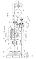
- the traveling transmission device 20 in which the power of the engine 4 is transmitted to the front wheels 1 and the rear wheels 2 is configured as shown in FIG.
- the traveling transmission device 20 has a front wheel differential mechanism 21 that transmits power to the left and right front wheels 1 (see FIG. 1) and a rear wheel that transmits power to the left and right rear wheels 2 (see FIG. 1).
- It has a wheel differential mechanism 22 and a mission 23 in which the power of the engine 4 as a power source is input and the input power is changed and transmitted to the front wheel differential mechanism 21 and the rear wheel differential mechanism 22.
- the front wheel differential mechanism 21 is provided inside the front wheel drive case 15 (see FIG. 1).
- the rear wheel differential mechanism 22 is housed in the rear portion of the mission case 13.
- Mission 23 is housed in mission case 13 as shown in FIG.
- the front portion of the transmission case 13 is detachably connected to the rear portion of the clutch housing 12 accommodating the main clutch 24, and the front case portion 13A accommodating the forward / backward switching device 25 and the like and the front portion rear portion of the front case portion 13A.
- the mission 23 includes a forward / backward switching device 25 in which the power of the output shaft 4a of the engine 4 is input via the main clutch 24 and the input power is converted into forward power and reverse power.
- the transmission 26 that shifts the forward power and the reverse power output by the forward / backward switching device 25, and the rear wheel transmission shaft 27 that transmits the forward power and the reverse power output from the transmission 26 to the rear wheel differential mechanism 22. It has a front wheel transmission device 28 to which forward power and reverse power output by the transmission 26 are input, and a front wheel transmission shaft 29 to transmit forward power and reverse power output from the front wheel transmission device 28 to the front wheel differential mechanism 21. are doing.
- Reference numeral 30 shown in FIG. 2 is a working clutch.
- the work clutch 30 transmits the power of the relay shaft 31 interlocked with the input shaft 25a of the forward / backward switching device 25 to the power take-out shaft 11 by being switched to the engaged state, and is switched to the disengaged state.
- the power transmission to the take-out shaft 11 is cut off.
- the forward / backward switching device 25 has an input shaft 25a interlocked with the output shaft 4a of the engine 4 via a main clutch 24, a forward clutch 25b provided on the input shaft 25a, and a reverse clutch 25c. have.
- the forward clutch 25b and the reverse clutch 25c are composed of a wet and hydraulically operated multi-plate clutch.
- the forward clutch 25b is switched to the engaged state and the reverse clutch 25c is switched to the disengaged state, so that the power of the engine 4 input by the input shaft 25a is converted into the forward power and the output gear. It is output from 25d.
- the forward clutch 25b is switched to the disengaged state and the reverse clutch 25c is switched to the engaged state, so that the power of the engine 4 input by the input shaft 25a is converted into the reverse power and the output gear. It is output from 25d.
- the transmission 26 has an input shaft 33 for inputting the power of the output gear 25d of the forward / reverse switching device 25, an intermediate shaft 34 externally fitted to the relay shaft 31 so as to be relatively rotatable, and an intermediate shaft 34. It has an output shaft 35 provided below the above, a main transmission 26A provided over the input shaft 33 and the intermediate shaft 34, and an auxiliary transmission 26B provided over the intermediate shaft 34 and the output shaft 35.
- the power of the input shaft 33 is main-shifted by the main transmission 26A to six stages of transmission power from the first speed to the sixth speed, and the main-shifted transmission power is high-speed and low-speed by the auxiliary transmission 6B.
- the sub-shifting power is sub-shifted to the two-step shifting power of the above, and the sub-shifting power is output from the output shaft 35.
- the rear wheel transmission shaft 27 is provided above the front wheel transmission shaft 29 and is arranged parallel to the front wheel transmission shaft 29.
- the rear wheel transmission shaft 27 is provided behind the output shaft 35 of the transmission 26 and is arranged in a straight line with respect to the output shaft 35.
- An emergency brake 36 is provided over the rear end of the output shaft 35 of the transmission 26 and the front end of the rear wheel transmission shaft 27.
- a front wheel clutch 40 is provided on the front wheel transmission shaft 29, and a plurality of disc springs 39 are provided on the front wheel transmission shaft 29 behind the front wheel clutch 40.
- the emergency brake 36 is provided so that the outer peripheral portion of the emergency brake 36 is inserted between the front wheel clutch 40 and the disc spring 39. As shown in FIG.
- the output shaft 35 and the rear wheel transmission shaft 27 are connected to each other by a rotating member 36a of the emergency brake 36 so as not to rotate relative to each other.
- the rotating member 36a supports the friction plate and is interlocked with each of the output shaft 35 and the rear wheel transmission shaft 27 by spline engagement.
- An input gear 22a of the rear wheel differential mechanism 22 is provided at the rear end of the rear wheel transmission shaft 27 so that it cannot rotate relative to each other.
- the forward power and reverse power of the output shaft 35 of the transmission 26 are transmitted to the rear wheel transmission shaft 27 by the rotating member 36a.
- the rear wheel transmission shaft 27 transmits the transmitted forward power and reverse power to the rear wheel differential mechanism 22 at the transmitted rotational speed.
- the emergency brake 36 is composed of a multi-plate friction brake.
- the emergency brake 36 is used when the engine is stopped.
- braking force is applied to the left and right rear wheels 2 via the rear wheel transmission shaft 27 and the rear wheel differential mechanism 22, and the output shaft 35, the front wheel transmission device 28, Braking force is applied to the left and right front wheels 1 via the front wheel transmission shaft 29, the front wheel output shaft 37, the rotation shaft 38, and the front wheel differential mechanism 21.
- the output unit of the front wheel transmission device 28 is provided on the front wheel transmission shaft 29.
- the rear end of the front wheel output shaft 37 is connected to the front end of the front wheel transmission shaft 29 so as not to rotate relative to each other, and the front end of the front wheel output shaft 37 and the input gear 21a of the front wheel differential mechanism 21 are interlocked and connected by the rotating shaft 38. Has been done.
- the forward power and reverse power output by the front wheel transmission device 28 are input to the front wheel transmission shaft 29.
- the front wheel transmission shaft 29 transmits the input forward power and reverse power to the front wheel differential mechanism 21 via the front wheel output shaft 37 and the rotary shaft 38.
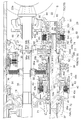
- the front wheel transmission device 28 has a front wheel clutch 40 and a front wheel speed-increasing clutch 60 which are arranged in the axial direction of the front wheel transmission shaft 29 and supported by the front wheel transmission shaft 29.
- the front wheel clutch 40 is arranged in front of the front wheel speed-up clutch 60, but the front wheel clutch 40 may be located behind the front wheel speed-up clutch 60.
- the front wheel clutch 40 includes a clutch hub 42 supported by the front wheel transmission shaft 29 so as to be relatively rotatable via a bearing 41, and a clutch drum 43 supported by the front wheel transmission shaft 29 so as to be relatively non-rotatable. And have.
- the boss portion 43a of the clutch drum 43 is fitted onto the front wheel transmission shaft 29, the boss portion 43a and the front wheel transmission shaft 29 are connected to each other by a key 44 so as not to rotate relative to each other, and the clutch drum 43 is relative to the front wheel transmission shaft 29. It is supported non-rotatably.
- the clutch hub 42 is provided with a constant velocity input gear 45 provided at the front portion of the clutch hub 42 so as not to rotate relative to each other.
- the constant velocity input gear 45 and the constant velocity transmission gear 46 provided on the output shaft 35 of the transmission 26 so as not to rotate relative to each other are meshed with each other.
- the transmission ratio between the constant velocity input gear 45 and the constant velocity transmission gear 46 is set to a transmission ratio that equalizes the rotation speed of the output shaft 35 and the rotation speed of the front wheel transmission shaft 29.
- a pair of internal spaces 43c are provided, which are partitioned by a rim portion 43b and arranged in the front-rear direction.
- a plurality of clutch plates 47 are provided over the clutch hub 42 and the clutch drum 43.
- a push member 48 that presses and operates the clutch plate 47 is slidably provided in the front internal space 43c.
- a first hydraulic piston 49 is slidably mounted in the rear internal space 43c of the pair of internal spaces 43c.
- the first hydraulic piston 49 and the pushing member 48 are interlocked and connected by connecting members 50 extending forward from a plurality of locations in the circumferential direction of the first hydraulic piston 49.
- the plurality of connecting members 50 slidably insert the rim portion 43b.
- the front wheel clutch 40 is a so-called wet and hydraulically operated multi-plate clutch.
- a plurality of disc springs 39 as first urging members are arranged in the axial direction of the front wheel transmission shaft 29 between the middle holder 70B that supports the front wheel transmission shaft 29 behind the front wheel clutch 40 and the front wheel clutch 40. It is fitted on the front wheel transmission shaft 29.
- the disc spring 39 is configured to urge the front wheel clutch 40 into the engaged state.
- the outer fitting of the disc spring 39 with respect to the front wheel transmission shaft 29 is interposed between the rear extension portion 43d of the boss portion 43a of the clutch drum 43 and the extension portion 43d and the disc spring 39. This is done via the support cylinder 51.
- the support cylinder 51 is received and supported from behind by a stopper portion 52 formed on the extension portion 43d.
- the plurality of disc springs 39 are received and supported from the rear by the stopper portion 53 formed at the rear portion of the support cylinder 51.
- a tubular urging force transmitting member 54 is externally fitted over the rear portion 49a of the first hydraulic piston 49 and the front portion of the support cylinder 51.
- the urging force transmitting member 54 is slidably fitted to the support cylinder 51.
- the front end portion of the urging force transmission member 54 is engaged with the step portion formed on the rear portion 49a of the first hydraulic piston 49 in a state of being in contact with the rear portion from the rear.
- the rear end portion of the urging force transmitting member 54 is engaged with the frontmost disc spring 39 of the plurality of disc springs 39 in a state of being in contact with the front end.
- the disc spring 39 pushes the urging force transmitting member 54 toward the first hydraulic piston 49 by the elastic restoring force, and the urging force transmitting member 54 pushes the first hydraulic piston 49 toward the rim portion 43b.
- the elastic restoring force of the disc spring 39 is transmitted to the first hydraulic piston 49 by the urging force transmission member 54, and the first hydraulic piston 49 is urged to the entering position by the disc spring 39.
- the front wheel clutch 40 is switched between the off state and the on state by the first hydraulic piston 49 and the disc spring 39.
- the supplied hydraulic pressure causes the first hydraulic piston 49 to operate at the cutting position against the urging force of the countersunk spring 39 and push it.
- the member 48 is slid toward the rim portion 43b by the first hydraulic piston 49, the pressure welding of the clutch plate 47 by the pushing member 48 is released, and the interlocking connection between the clutch drum 43 and the clutch hub 42 by the clutch plate 47 is released. , The front wheel clutch 40 is in the disengaged state.
- the front wheel clutch 40 When the front wheel clutch 40 is switched to the disengaged state, the power transmission from the constant velocity transmission gear 46 to the front wheel transmission shaft 29 is cut off by the front wheel clutch 40. That is, when the front wheel clutch 40 is switched to the disengaged state, the transmission of the forward power and the reverse power output by the transmission 26 to the front wheel transmission shaft 29 is cut off, and the power transmission to the front wheel differential mechanism 21 is cut off.
- the first hydraulic piston 49 When hydraulic pressure is discharged from between the first hydraulic piston 49 and the rim portion 43b, the first hydraulic piston 49 is operated to the entering position by the urging force of the countersunk spring 39, and the pushing member 48 is clutched by the first hydraulic piston 49.
- the clutch plate 47 is slid toward the plate 47, the clutch plate 47 is pressure-welded by the pushing member 48, the clutch drum 43 and the clutch hub 42 are interlocked and connected by the clutch plate 47, and the front wheel clutch 40 is engaged.
- the front wheel clutch 40 When the front wheel clutch 40 is switched to the engaged state, the power transmitted from the output shaft 35 of the transmission 26 to the constant speed transmission gear 46 is transmitted to the front wheel transmission shaft 29 by the front wheel clutch 40, and the front wheel differential from the front wheel transmission shaft 29. It is transmitted to the mechanism 21. In this case, the rotation speed of the output shaft 35 and the rotation speed of the front wheel transmission shaft 29 become equal depending on the transmission ratio between the constant velocity transmission gear 46 and the constant velocity input gear 45.
- the front wheel clutch 40 Since the power of the output shaft 35 is transmitted to the rear wheel transmission shaft 27 at the same rotational speed of the output shaft 35, the front wheel clutch 40 is switched to the engaged state, so that the average peripheral speed of the left and right front wheels 1 and the left and right Power is transmitted to the front wheel transmission shaft 29 in a state where the average peripheral speed of the rear wheels 2 is equal to that of the rear wheels 2.
- the front wheel speed-increasing clutch 60 includes a clutch hub 62 supported by the front wheel transmission shaft 29 so as to be relatively rotatable via a bearing 61, and a clutch supported by the front wheel transmission shaft 29 so as to be relatively non-rotatable. It has a drum 63 and.
- the support of the clutch hub 62 to the front wheel transmission shaft 29 is such that the boss portion 62a of the clutch hub 62 is externally fitted to the rearward extension portion 63b of the boss portion 63a in the clutch drum 63, and the extension portion 63b and the boss portion 62a are supported. This is done by interposing a bearing 61 between them.
- the clutch hub 62 includes a speed-increasing input gear 64 provided at the rear portion of the clutch hub 62 so as not to rotate relative to each other.
- the speed-up input gear 64 and the speed-up transmission gear 65 provided on the rear wheel transmission shaft 27 so as not to rotate relative to each other are in mesh with each other.
- the transmission ratio between the speed-up input gear 64 and the speed-up transmission gear 65 is set to a transmission ratio that makes the rotation speed of the front wheel transmission shaft 29 faster than the rotation speed of the rear wheel transmission shaft 27.
- a plurality of clutch plates 66 are provided over the clutch hub 62 and the clutch drum 63.
- a second hydraulic piston 67 is slidably mounted in the internal space 63c.
- a coil spring 68 is provided as a second urging member in the internal space 63c.
- the coil spring 68 is interposed between the end portion of the second hydraulic piston 67 and the stopper portion 69 formed on the boss portion 63a.
- the coil spring 68 urges the second hydraulic piston 67 to the cut position and urges the front wheel speed-up clutch 60 to the cut state.
- the front wheel speed-up clutch 60 is a so-called wet and hydraulically operated multi-plate clutch.
- the front wheel speed-up clutch 60 is switched between the engaged state and the engaged state by the second hydraulic piston 67 and the coil spring 68.
- the front wheel speed-up clutch 60 When the front wheel speed-up clutch 60 is switched to the engaged state, the power transmitted from the output shaft 35 of the transmission 26 to the speed-up transmission gear 65 via the rear wheel transmission shaft 27 is transmitted by the front wheel speed-up clutch 60 to the front wheel transmission shaft 29. Is transmitted from the front wheel transmission shaft 29 to the front wheel differential mechanism 21. In this case, the rotation speed of the front wheel transmission shaft 29 becomes faster than the rotation speed of the output shaft 35 due to the transmission ratio between the speed-up transmission gear 65 and the speed-up input gear 64. Since the power of the output shaft 35 is transmitted to the rear wheel transmission shaft 27 at the same rotational speed of the output shaft 35, the front wheel acceleration clutch 60 is switched to the engaged state, so that the average peripheral speed of the left and right front wheels 1 is reached. Power is transmitted to the front wheel transmission shaft 29 in a state where the speed is faster than the average peripheral speed of the left and right rear wheels 2.
- the front wheel speed-up clutch 60 When the front wheel speed-up clutch 60 is switched to the disengaged state, the power transmission from the speed-up transmission gear 65 to the front wheel transmission shaft 29 is cut off by the front wheel speed-up clutch 60.
- the front wheel speed-up clutch 60 When the front wheel speed-up clutch 60 is switched to the disengaged state, the transmission of the forward power and the reverse power output by the transmission 26 to the front wheel transmission shaft 29 is cut off, and the power transmission to the front wheel differential mechanism 21 is cut off.
- the power of the output shaft 35 of the transmission 26 is transmitted at the same rotational speed by the front wheel transmission gear 46 and the front wheel clutch 40. It is transmitted to the shaft 29 and transmitted from the front wheel transmission shaft 29 to the front wheel differential mechanism 21, and the power transmission from the speed-up transmission gear 65 to the front wheel transmission shaft 29 is cut off by the front wheel speed-up clutch 60.
- the power of the output shaft 35 of the transmission 26 is transmitted to the rear wheel differential mechanism 22 by the rear wheel transmission shaft 27 at the same rotational speed.
- the front wheels 1 and the rear wheels 2 are driven, and the front and rear wheels have a constant speed of 4WD, in which the average peripheral speeds of the left and right front wheels 1 and the average peripheral speeds of the left and right rear wheels 2 are equal. Will be done.
- the front wheel acceleration clutch 60 is disengaged by the coil spring 68. Even if it is switched, the front wheel clutch 40 is switched to the engaged state by the countersunk spring 39, the constant velocity transmission gear 46 and the front wheel transmission shaft 29 are connected by the front wheel clutch 40, and the front wheel 1 is in the idle state.
- the braking force of the emergency brake 36 can be applied to the front wheels 1 via the front wheel clutch 40, the front wheel transmission shaft 29, and the like.
- the front wheel clutch 40 can be firmly held in the engaged state by the strong urging force of the disc spring 39 so that the front wheel clutch 40 does not slip due to the operating force applied from the front wheel 1 to the front wheel clutch 40. Even on sloping terrain, the brakes can be applied firmly to the vehicle body.
- the front wheel transmission shaft 29 is supported by a holder 70 that supports three points in the axial direction of the front wheel transmission shaft 29.
- the foremost holder 70 among the three holders 70 will be referred to as a front holder 70A.
- the rearmost holder 70 (corresponding to the "second holder” constituting the claim) is referred to as a rear holder 70C.
- the holder 70 between the front holder 70A and the rear holder 70C (corresponding to the "holder” constituting the claim) is referred to as a middle holder 70B.
- the front holder 70A is composed of a wall portion of the mission case 13 arranged in the internal space S of the mission case 13.
- the front holder 70A has a boss portion 71 through which the front wheel transmission shaft 29 is inserted.
- a portion 29a located in front of the front wheel clutch 40 is rotatably supported by a boss portion 71 of the front holder 70A via a bearing 72.
- the middle holder 70B is formed separately from the mission case 13.
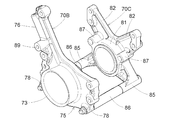
- the middle holder 70B has a boss portion 73 through which the front wheel transmission shaft 29 is inserted, a holder portion 75 having a support portion 74 projecting rearward from the boss portion 73, and a connecting arm extending upward from the holder portion 75. It has a part 76 and.
- the support portion 74 is configured to fit inside the annular portion 63e formed in the front portion of the clutch drum 63 as a rotating member in the front wheel speed-up clutch 60.
- a bearing 77 is interposed between the support portion 74 and the annular portion 63e.
- the middle holder 70B is supported by the wall portion 79 in a state where the holder portion 75 is located at a position separated from the wall portion 79.
- a portion 29b located between the front wheel clutch 40 and the front wheel speed-up clutch 60 is rotatably supported by a boss portion 73 of the middle holder 70B via a bearing 80.
- the clutch drum 63 of the front wheel speed-up clutch 60 is rotatably supported by a support portion 74 of the middle holder 70B via a bearing 77.
- the rear holder 70C is formed separately from the mission case 13.
- the rear holder 70C has a boss portion 81 and a pair of connecting arm portions 82 extending upward from the boss portion 81.
- the boss portion 81 is configured to be externally fitted to the extension portion 63b of the boss portion 63a of the clutch drum 63 via the bearing 83.
- a wall portion 79 supporting the middle holder 70B and another wall portion 84 are arranged behind the wall portion 79 and provided in the internal space S of the mission case 13.
- the connecting arm portion 82 of the connecting arm portion 82 and the boss portion 81 is abutted against the wall portion 84 and is detachably connected by the connecting bolt 82a.
- the rear holder 70C is supported by the wall portion 84 in a state where the boss portion 81 is located at a position separated from the wall portion 84.
- the extension portion 63b of the boss portion 63a of the clutch drum 63 is rotatably supported by the boss portion 81 via the bearing 83.
- the front wheel transmission shaft 29 rotates on the boss portion 81 of the rear holder 70C via the boss portion 63a and the bearing 83. It is supported as much as possible.
- spacer connecting portions 78 are formed at two positions of the holder portion 75, which is a portion of the middle holder 70B that is separated from the wall portion 79.
- Spacer connecting portions 85 are formed at two positions of the boss portion 81, which is a portion of the rear holder 70C that is separated from the wall portion 84.
- the spacer 86 is connected to the spacer connecting portion 78 of the middle holder 70B and the spacer connecting portion 85 of the rear holder 70C.
- the portion of the middle holder 70B that is detached from the wall portion 79 and the portion of the rear holder 70C that is detached from the wall portion 84 are connected by two spacers 86.
- the front wheel speed-up clutch 60 is positioned between the middle holder 70B and the rear holder 70C so that the distance between the portion of the middle holder 70B that is detached from the wall portion 79 and the portion of the rear holder 70C that is detached from the wall portion 84 is
- the spacer 86 is set at an interval suitable for the clutch.
- the middle holder 70B and the rear holder 70C reinforce each other by using the spacer 86 as a reinforcing member.
- a first supply / discharge port 90 for supplying / discharging hydraulic pressure between the rim portion 43b and the first hydraulic piston 49 is formed on the boss portion 43a of the clutch drum 43 of the front wheel clutch 40.
- the first supply / discharge port 90 and the operation valve (not shown) provided outside the mission case 13 are provided via the first operation oil passage 91 formed over the front wheel transmission shaft 29 and the middle holder 70B. It is connected.
- the first operating oil passage 91 is a portion corresponding to the holder oil passage portion 91a to a portion corresponding to the first supply / discharge port 90 in the holder oil passage portion 91a bored in the middle holder 70B and the front wheel transmission shaft 29. It has a shaft oil passage portion 91b that has been bored. In the front wheel transmission shaft 29, the shaft hole 92 formed over the end portion 91t on the middle holder side of the shaft oil passage portion 91b and the end portion 29c of the front wheel transmission shaft 29 does not form the first operation oil passage 91. This is possible because of the drilling of the shaft oil passage portion 91b.
- the operation valve When the operation valve is switched to the cut position, hydraulic pressure is supplied from the operation valve to the first operation oil passage 91, and the first operation oil passage 91 transfers the supplied hydraulic pressure from the first supply / discharge port 90 to the rim portion 43b. It is supplied between the 1 hydraulic piston 49 and the 1st hydraulic piston 49 is operated to the cutting position against the disc spring 39.
- the operation valve When the operation valve is switched to the entry position, the pressure oil between the rim portion 43b and the first hydraulic piston 49 is returned to the first operation oil passage 91 via the first supply / discharge port 90, and the first operation oil passage 91 discharges the returned pressure oil to the operation valve and operates the first hydraulic piston 49 at the entering position by the disc spring 39. That is, the first operation oil passage 91 operates by supplying and discharging hydraulic pressure to switch the front wheel clutch 40 between the engaged state and the disengaged state.
- a second supply / discharge port 93 for supplying / discharging hydraulic pressure between the rim portion 63d and the second hydraulic piston 67 is formed in the boss portion 63a of the clutch drum 63 of the front wheel speed-increasing clutch 60.
- the second supply / discharge port 93 and the operation valve (not shown) provided outside the mission case 13 are provided via the second operation oil passage 94 formed over the front wheel transmission shaft 29 and the middle holder 70B. It is connected.
- the second operation oil passage 94 includes a holder oil passage portion 94a bored in the middle holder 70B and a portion of the front wheel transmission shaft 29 corresponding to the holder oil passage portion 94a to a portion corresponding to the second supply / discharge port 93. It has a shaft oil passage portion 94b that has been bored. In the front wheel transmission shaft 29, the shaft hole 95 formed over the end of the shaft oil passage portion 94b on the middle holder side and the end portion 29c of the front wheel transmission shaft 29 does not form the second operation oil passage 94. , It is possible to drill the shaft oil passage portion 94b.
- the front wheel speed-up clutch 60 is arranged below the internal space S of the transmission case 13.
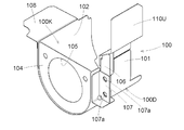
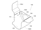
- a speed-increasing clutch cover 100 that covers the front wheel speed-up clutch 60 is provided in the internal space S.
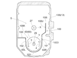
- the speed-increasing clutch cover 100 has an opening 100K formed upward, as shown in FIGS. 8, 9 and 10.
- the lubricating oil stored in the transmission case 13 flows into the speed-increasing clutch cover 100 through the opening 100K, and the lubricating oil can be stored in the peripheral region of the front wheel speed-up clutch 60 in the internal space S.
- the lubricating oil located in the peripheral region of the front wheel speeding clutch 60 is agitated by the rotation of the front wheel speeding clutch 60, but the lubricating oil located in the region outside the peripheral region of the front wheel speeding clutch 60 is combined with the front wheel speeding clutch.
- the speed-increasing clutch cover 100 suppresses the agitation of the lubricating oil by 60.
- the speed-increasing clutch cover 100 is arranged between the middle holder 70B and the rear holder 70C, as shown in FIGS. 5 and 6.
- the rear portion of the speed-up clutch cover 100 is connected to the support portion 87 (see FIG. 4) formed in the rear holder 70C by a connecting bolt, and the speed-up clutch cover 100 is detachably supported by the rear holder 70C.
- the speed-increasing clutch cover 100 includes a lower cover portion 100D located below the upper end portion 60a of the front wheel speed-increasing clutch 60 and an upper portion extending upward from the lower cover portion 100D. It has a cover portion of 100U.
- the lower cover portion 100D covers the first lateral wall portion 101 that covers the front wheel acceleration clutch 60 from the right lateral side, and the front wheel acceleration clutch 60 from the left lateral side. It has a second lateral wall portion 102, a bottom wall portion 103 that covers the front wheel speed-up clutch 60 from below, and a rear wall portion 104 that covers the front wheel speed-up clutch 60 from the rear.
- a lateral cover portion 108 extends from the upper end portion of the second lateral wall portion 102 toward the lateral outer side of the lower cover portion 100D. As shown in FIG. 7, the sideways cover portion 108 extends to the side wall portion of the mission case 13.
- the space between the second side wall portion 102 and the mission case 13 is closed by the sideways cover portion 108.
- the bottom wall portion 103 is formed in an arc shape along the lower portion of the front wheel speed-up clutch 60.
- a through hole 105 into which the boss portion 81 of the rear holder 70C enters is opened in the rear wall portion 104.
- the upper cover portion 100U extends upward from the first lateral wall portion 101 to a position higher than the axis X of the rear wheel transmission shaft 27.
- the upper end 100t of the upper cover portion 100U as the upper end of the speed-increasing clutch cover 100 is located at a position higher than the axis X of the rear wheel transmission shaft 27.
- the upper cover portion 100U is formed separately from the lower cover portion 100D.
- the connecting portion 106 formed in the lower part of the upper cover portion 100U and the supporting portion 107 formed in the first lateral wall portion 101 of the lower cover portion 100D are connected by a connecting bolt (not shown) attached to the bolt hole 107a. Will be done.
- the upper cover portion 100U and the lower cover portion 100D are separably connected.
- the speed-up clutch cover 100 acts as a wave-proof against the lubricating oil agitated by the rotation of the front wheel speed-up clutch 60, and the region deviates from the peripheral region of the front wheel speed-up clutch 60. Stirring by the front wheel speed-up clutch 60 is suppressed from reaching the located lubricating oil.
- the upper end 100t of the upper cover portion 100U as the upper end of the speed-increasing clutch cover 100 is located at a position higher than the axis X of the rear wheel transmission shaft 27.
- Lubricating oil is generally stored in the transmission case 13 in a state where the oil level is located at the axle core X of the rear wheel transmission shaft 27 or at a location above the axle core X, but the front wheel speed-up clutch
- the upper cover portion 100U effectively suppresses the flow of the lubricating oil generated by the stirring of the lubricating oil by the 60 to reach the lubricating oil located in a region outside the peripheral region of the front wheel speed-up clutch 60.
- the upper cover portion 100U is extended from only the first lateral wall portion 101 of the first lateral wall portion 101 and the second lateral wall portion 102.
- the right lateral side portion 63R of the clutch drum 63 is in the ascending direction as indicated by the arrow a.
- the lubricating oil that rotates and the left lateral side 63L of the clutch drum 63 rotates in the downward direction as indicated by the arrow b and is agitated by the right lateral 63R flows upward and is agitated by the left lateral 63L.
- the lubricating oil flows downward.
- the first lateral wall portion 101 of the lower cover portion 100D corresponds to the right lateral side portion 63R of the clutch drum 63
- the second lateral wall portion 102 of the lower cover portion 100D corresponds to the left lateral side portion 63L of the clutch drum 63
- the upper cover portion 100U is extended upward from the first lateral wall portion 101 corresponding to the right lateral side portion 63R that causes the upward flow of the lubricating oil, and the upper cover portion 100U is effective against the lubricating oil that flows upward. It acts as a wave barrier.
- the front wheel clutch 40 is arranged in the lower part of the internal space S of the transmission case 13.
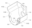
- a front wheel clutch cover 110 that covers the front wheel clutch 40 is provided in the internal space S.
- the front wheel clutch cover 110 has an upwardly formed opening 110K, as shown in FIGS. 11 and 12.
- the lubricating oil stored in the mission case 13 flows into the front wheel clutch cover 110 through the opening 110K, and the lubricating oil can be stored in the peripheral region of the front wheel clutch 40 in the internal space S.
- the front wheel clutch cover 110 acts as a wave shield against the lubricating oil that is agitated by the rotation of the front wheel clutch 40 in the peripheral region of the front wheel clutch 40, and the front wheel clutch is applied to the lubricating oil located in the region outside the peripheral region of the front wheel clutch 40. The stirring by 40 is suppressed.
- the front wheel clutch cover 110 is arranged between the front holder 70A and the middle holder 70B, as shown in FIGS. 5 and 6.
- the front portion of the front wheel clutch cover 110 is connected to the support portion 88 formed in the front holder 70A by a connecting bolt, and the rear portion of the front wheel clutch cover 110 is connected to the support portion 89 (see FIG. 4) formed in the middle holder 70B.
- the front wheel clutch cover 110 is detachably supported by the front holder 70A and the middle holder 70B.
- the front wheel clutch cover 110 includes a lower cover portion 110D located below the upper end portion 40a of the front wheel clutch 40, and a first lateral wall portion 111 of the lower cover portion 110D. It has an upper cover portion 110U extending upward from the rear wall portion 115.
- the upper cover portion 110U is integrally formed with the first lateral wall portion 111 and the rear wall portion 115 of the lower cover portion 110D.
- the upper cover portion 110U is extended to a position higher than the shaft core X of the rear wheel transmission shaft 27.
- the upper end 110t of the upper cover portion 110U as the upper end of the front wheel clutch cover 110 is located at a position higher than the shaft core X.
- the lower cover portion 110D includes a first lateral wall portion 111 that covers the front wheel clutch 40 from the right lateral side, and a second lateral wall portion that covers the front wheel clutch 40 from the left lateral side. It has 112, a bottom wall portion 113 that covers the front wheel clutch 40 from below, a front wall portion 114 that covers the front wheel clutch 40 from the front, and a rear wall portion 115 that covers the front wheel clutch 40 from the rear.
- the bottom wall portion 113 is formed in an arc shape along the lower portion of the front wheel clutch 40.
- the front wall portion 114 is configured to be removable with respect to a portion of the lower cover portion 110D other than the front cover portion.
- a notch 116 through which the front wheel transmission shaft 29 is inserted is formed in the front wall portion 114.
- a through hole 117 into which the boss portion 73 of the middle holder 70B enters is opened in the rear wall portion 115.
- a through hole 118 through which the rear wheel transmission shaft 27 is inserted is opened in the upper cover portion 110U.
- the upper cover portions 100U and 110U are extended from only the first lateral wall portions of the lower cover portions 100D and 110D, and the first lateral wall portions and the lower cover portions 100D and 110D are shown. It may be extended from both of the second side wall portions.
- an example in which the coil spring 68 for urging the front wheel speed-increasing clutch 60 in the disengaged state is adopted is not limited to this.
- various urging members such as disc springs can be adopted.
- the present invention can be applied to an engine equipped with an electric motor as a power source instead of an engine, or an engine and an electric motor provided as a power source.
Landscapes
- Engineering & Computer Science (AREA)
- Transportation (AREA)
- Mechanical Engineering (AREA)
- Chemical & Material Sciences (AREA)
- Combustion & Propulsion (AREA)
- Arrangement And Driving Of Transmission Devices (AREA)
- Arrangement Of Transmissions (AREA)
Abstract
前輪クラッチ(40)及び前輪増速クラッチ(60)が前輪伝動軸(29)に支持されている。前輪クラッチ(40)と前輪増速クラッチ(60)との間において、前輪伝動軸(29)を支持するホルダー(70B)が備えられている。前輪クラッチ(40)を切り換え操作する第1操作油路(91)がホルダー(70B)と前輪伝動軸(29)とに亘って穿設されている。前輪増速クラッチ(60)を切り換え操作する第2操作油路(94)がホルダー(70B)と前輪伝動軸(29)とに亘って穿設されている。
Description
本発明は、左右の前車輪に動力伝達する前輪差動機構と、左右の後車輪に動力伝達する後輪差動機構と、動力源の動力が入力され、入力された動力を前記前輪差動機構及び前記後輪差動機構に伝達するミッションと、が備えられたトラクタの走行伝動装置に関する。
上記したトラクタの走行伝動装置において、例えば特許文献1に示されるように、前輪差動機構に動力を伝達する伝動軸に等速クラッチ及び増速クラッチが設けられ、増速クラッチが切断され、かつ、等速クラッチが接続されると、後輪デフ装置に伝達される動力が後輪と前輪とがほぼ同じ周速度で回転するように伝動軸に動力伝達され、等速クラッチが切断され、かつ、増速クラッチが接続されると、後輪デフ装置に伝達される動力が増速して伝動軸に伝達され、増速クラッチ及び等速クラッチの両方が切断されると、前輪には動力が伝達されずに、トラクタが後輪のみで駆動されるものがあった。
特許文献1に示されるものでは、等速クラッチのクラッチボディと増速クラッチのクラッチボディとが一体形成された状態で伝動軸に設けられている。
上記したトラクタの走行伝動装置において、前輪伝動軸に動力伝達する入り状態と、前輪伝動軸に対する動力伝達を絶つ切り状態と、に切り換え可能であり、かつ、入り状態において左右の前車輪の平均周速度と左右の後車輪の平均周速度とが等しくなる状態で前輪伝動軸に動力伝達する前輪クラッチと、前輪伝動軸に動力伝達する入り状態と、前輪伝動軸に対する動力伝達を絶つ切り状態と、に切り換え可能であり、かつ、入り状態において左右の前車輪の平均周速度が左右の後車輪の平均周速度よりも速くなる状態で前輪伝動軸に動力伝達する前輪増速クラッチと、を前輪伝動軸に支持することにより、前車輪及び後車輪のうちの後車輪のみが駆動される2駆状態と、左右の前車輪の平均周速度と左右の後車輪の平均周速度とが等しくなる前後輪等速の4駆状態と、左右の前車輪の平均周速度が左右の後車輪の平均周速度よりも速くなる前輪増速の4駆状態とを現出可能になる。この種のトラクタの走行伝動装置において、前輪クラッチを切り換え操作する第1操作油路、前輪増速クラッチを切り換え操作する第2操作油路を前輪伝動軸に穿設するのに、従来の技術を採用した場合、前輪伝動軸において、前輪クラッチ及び前輪増速クラッチの一方のクラッチに対して他方のクラッチが位置する側と反対側の部位から第1操作油路及び第2操作油路を操作対象の前輪クラッチや前輪増速クラッチに向けて延ばすので、第1操作油路及び第2操作油路の一方の操作油路は、クラッチ側と反対側の部分において他方の操作油路と前輪伝動軸の径方向に並ぶことになり、この並びのために操作油路の長さが長くなる。
この種のトラクタの走行伝動装置では、前輪増速クラッチの回動によってミッションケース内の潤滑油が撹拌されるので、かつ、前輪増速クラッチの回動速度は、前輪増速のために高速になるので、前輪増速クラッチによる潤滑油の撹拌に起因する潤滑油の温度上昇を抑制することが望まれている。
本発明は、2駆状態、前後輪等速の4駆状態及び前輪増速の4駆状態の現出を可能にするものにおいて、操作油路の長さを短く済ませることができるトラクタの走行伝動装置、及び、前輪増速クラッチの回動による潤滑油の温度上昇を安価に抑制できるトラクタの走行伝動装置を提供する。
本発明によるトラクタの走行伝動装置は、左右の前車輪に動力伝達する前輪差動機構と、左右の後車輪に動力伝達する後輪差動機構と、動力源の動力が入力され、入力された動力を前記前輪差動機構及び前記後輪差動機構に伝達するミッションと、が備えられ、前記ミッションは、前記前輪差動機構に動力を伝達する前輪伝動軸と、前記前輪伝動軸に動力伝達する入り状態と、前記前輪伝動軸に対する動力伝達を絶つ切り状態と、に切り換え可能であり、かつ、前記入り状態において前記左右の前車輪の平均周速度と前記左右の後車輪の平均周速度とが等しくなる状態で前記前輪伝動軸に動力伝達する前輪クラッチと、前記前輪伝動軸に動力伝達する入り状態と、前記前輪伝動軸に対する動力伝達を絶つ切り状態と、に切り換え可能であり、かつ、前記入り状態において前記左右の前車輪の平均周速度が前記左右の後車輪の平均周速度よりも速くなる状態で前記前輪伝動軸に動力伝達する前輪増速クラッチと、を有し、前記前輪クラッチ及び前記前輪増速クラッチは、前記前輪伝動軸の軸芯方向に並ぶ状態で前記前輪伝動軸に支持されており、前記前輪クラッチと前記前輪増速クラッチとの間において、前記前輪伝動軸を回転可能に支持するホルダーが備えられ、前記前輪クラッチを切り換え操作する第1操作油路が前記前輪伝動軸と前記ホルダーとに亘って穿設されており、前記前輪増速クラッチを切り換え操作する第2操作油路が前記前輪伝動軸と前記ホルダーとに亘って穿設されている。
本構成によると、前輪クラッチが切り状態に切り換えられ、かつ、前輪増速クラッチが切り状態に切り換えられることにより、前輪伝動軸に対する動力伝達が絶たれて前輪差動機構に動力が伝達されないので、前車輪及び後車輪のうち後車輪のみが駆動される。前輪クラッチが入り状態に切り換えられ、前輪増速クラッチが切り状態に切り換えられることにより、左右の前車輪の平均周速度と左右の後車輪の平均周速度とが等しくなる状態で前輪伝動軸に動力伝達されてこの前輪伝動軸の動力が前輪差動機構に伝達されるので、左右の前車輪の平均周速度と左右の後車輪の平均周速度とが等しくなる状態で前車輪及び後車輪が駆動される。前輪クラッチが切り状態に切り換えられ、前輪増速クラッチが入り状態に切り換えられることにより、左右の前車輪の平均周速度が左右の後車輪の平均周速度よりも速くなる状態で前輪伝動軸に動力伝達されてこの前輪伝動軸の動力が前輪差動機構に伝達されるので、左右の前車輪の平均周速度が左右の後車輪の平均周速度よりも速くなる状態で前車輪及び後車輪が駆動される。
第1操作油路のうちの前輪伝動軸に位置する部分は、前輪伝動軸のうちのホルダーに対応する部位から前輪伝動軸のうちの前輪クラッチに対応する部位に延び、第2操作油路のうちの前輪伝動軸に位置する部分は、前輪伝動軸のうちのホルダーに対応する部位から前輪伝動軸のうちの前輪増速クラッチに対応する部位に延びるので、前輪伝動軸において、第1操作油路及び第2操作油路が前輪伝動軸の径方向に並ばない。
従って、後輪のみが駆動される2駆状態、前後輪等速の4駆状態、及び、前輪増速の4駆状態を現出することができ、かつ、第1操作油路及び第2操作油路を前輪伝動軸に穿設するものにおいて、第1操作油路及び第2操作油路の長さを短く済ませられる。
本発明においては、前記ホルダーに、前記前輪増速クラッチの回転部材に相対回転可能に嵌合して前記回転部材を支持する支持部が備えられており、前記回転部材と前記支持部との間にベアリングが介装されていると好適である。
本構成によると、ホルダーを回転部材の支持部材に活用した構造簡単な支持構造によって前輪増速クラッチをスムーズに回動するようにしっかり支持させることができる。
本発明においては、前記ミッションを収容するミッションケースが備えられ、前記ホルダーは、前記ミッションケースと別体に形成された状態で前記ミッションケースの壁部に支持されており、前記前輪増速クラッチに対して前記前輪クラッチと反対側に位置する箇所で前記前輪伝動軸を回転可能に支持する第2ホルダーが備えられ、前記第2ホルダーは、前記ミッションケースと別体に形成された状態で前記ミッションケースの前記壁部と別の壁部に支持されていると好適である。
本構成によると、ミッションケースの壁部に前輪伝動軸用の支持部を備えなくとも、前輪増速クラッチに対して前輪クラッチが位置する側と反対側において前輪伝動軸が第2ホルダーによって支持されるので、ミッションケースを簡素な形状に形成しつつ、前輪伝動軸及び前輪増速クラッチをしっかり支持させることができる。
本発明においては、前記ホルダーのうちの前記壁部から外れた部分と、前記第2ホルダーのうちの前記別の壁部から外れた部分と、に連結され、前記ホルダーと前記第2ホルダーとの間隔を設定するスペーサが備えられていると好適である。
本構成によると、ホルダーのうちのミッションケースの壁部から外れた部位と、第2ホルダーうちのミッションケースの壁部から外れた部位との間隔をホルダーと第2ホルダーとの間に前輪増速クラッチを位置させるのに適切な距離の間隔にスペーサによって設定できるので、ホルダー及び第2ホルダーが壁部に片持ち状態で支持されるものでありながら、前輪伝動軸及び前輪増速クラッチをしっかり支持させることができる。
本発明においては、前記前輪クラッチを前記入り状態に付勢する第1付勢部材が備えられ、前記前輪クラッチに装備され、かつ、前記第1操作油路によって供給される油圧によって作動して前記前輪クラッチを前記第1付勢部材に抗して前記切り状態に操作する第1油圧ピストンが備えられ、前記前輪増速クラッチを前記切り状態に付勢する第2付勢部材が備えられ、前記前輪増速クラッチに装備され、かつ、前記第2操作油路によって供給される油圧によって作動して前記前輪増速クラッチを前記第2付勢部材に抗して入り状態に操作する第2油圧ピストンが備えられ、前記第1付勢部材は、前記前輪クラッチと前記ホルダーとの間に設けられており、前記前輪伝動軸にスライド可能に支持され、前記第1付勢部材の付勢力を前記第1油圧ピストンに伝達する付勢力伝達部材が備えられていると好適である。
本構成によると、例えばエンジンが停止した場合など、油圧供給源が停止して第1油圧ピストン及び第2油圧ピストンに対する油圧供給が停止しても、前輪クラッチが第1付勢部材によって入り状態に切り換えられ、前輪増速クラッチが第2付勢部材によって切り状態に切り換えられるので、前車輪が前輪クラッチによってブレーキに繋がれるようにできる。第1付勢部材が前輪クラッチから外れた箇所に位置するので、前輪クラッチに装備された付勢部材に比べ、第1付勢部材を大型に構成するなど、強い付勢力を具備するようにできるので、前輪クラッチを前車輪による回動操作力に抗して第1付勢部材によって入り状態にしっかり維持されるようにできる。
つまり、傾斜地において、第1油圧ピストン及び第2油圧ピストンに対する油圧供給が停止しても、車体にしっかりブレーキを掛けることができる。
本発明においては、前記第1付勢部材は、皿ばねであると好適である。
本構成によると、第1付勢部材の装備に必要なスペースを小スペースに済ませつつ、前輪クラッチを入り状態に付勢する強い付勢力を具備させることができる。
本発明においては、前記前輪伝動軸に対して平行な状態で設けられ、前記後輪差動機構に動力伝達する後輪伝動軸が備えられ、前記後輪伝動軸に設けられた緊急ブレーキが備えられ、前記緊急ブレーキの外周部が前記前輪クラッチと前記皿ばねとの間に入り込んでいると好適である。
本構成によると、前輪クラッチと皿ばねとの間の空間を緊急ブレーキの設置スペースに活用するので、緊急ブレーキを備えたものをコンパクトに得ることができる。
本発明においては、前記ミッションを収容するミッションケースが備えられ、前記前輪増速クラッチは、前記ミッションケースの内部空間の下部に配置されており、前記内部空間に設けられ、前記前輪増速クラッチを覆う増速クラッチカバーが備えられ、前記増速クラッチカバーは、上向きに形成された開口を有していると好適である。
本構成によると、ミッションケース内に貯留される潤滑油が開口を介して増速クラッチカバーの内部に流入するので、ミッションケースの内部空間のうちの前輪増速クラッチの周辺領域に潤滑油を貯留できる。前輪増速クラッチの周辺領域に位置する潤滑油が前輪増速クラッチの回動によって撹拌されるが、撹拌された潤滑油に対して増速クラッチカバーが防波作用するので、前輪増速クラッチの周辺領域から外れた領域に位置する潤滑油に前輪増速クラッチによる撹拌が及び難く、ミッションケース内の潤滑油が昇温することを抑制できる。
本発明においては、前記ミッションを収容するミッションケースが備えられ、前記前輪クラッチは、前記ミッションケースの内部空間の下部に配置されており、前記内部空間に設けられ、前記前輪クラッチを覆う前輪クラッチカバーが備えられ、前記前輪クラッチカバーは、上向きに形成された開口を有していると好適である。
本構成によると、ミッションケース内に貯留される潤滑油が開口を介して前輪クラッチカバーの内部に流入するので、ミッションケースの内部空間のうちの前輪クラッチの周辺領域に潤滑油を貯留できる。前輪クラッチの周辺領域に位置する潤滑油が前輪クラッチの回動によって撹拌されるが、撹拌された潤滑油に対して前輪クラッチカバーが防波作用するので、前輪クラッチの周辺領域から外れた領域に位置する潤滑油に前輪クラッチによる撹拌が及び難く、ミッションケース内の潤滑油が昇温することを抑制できる。
別の本発明によるトラクタの走行伝動装置は、左右の前車輪に動力伝達する前輪差動機構と、左右の後車輪に動力伝達する後輪差動機構と、動力源の動力が入力され、入力された動力を前記前輪差動機構及び前記後輪差動機構に伝達するミッションと、前記ミッションを収容するミッションケースと、が備えられ、前記ミッションは、前記前輪差動機構に動力を伝達する前輪伝動軸と、前記左右の前車輪の平均周速度と前記左右の後車輪の平均周速度とが等しくなる状態で前記前輪伝動軸に動力伝達する前輪クラッチと、前記左右の前車輪の平均周速度が前記左右の後車輪の平均周速度よりも速くなる状態で前記前輪伝動軸に動力伝達する前輪増速クラッチと、を有し、前記前輪増速クラッチは、前記ミッションケースの内部空間の下部に配置されており、前記内部空間に設けられ、前記前輪増速クラッチを覆う増速クラッチカバーが備えられ、前記増速クラッチカバーは、上向きに形成された開口を有している。
本構成によると、ミッションケース内に貯留される潤滑油が開口を介して増速クラッチカバーの内部に流入するので、ミッションケースの内部空間のうちの前輪増速クラッチの周辺領域に潤滑油を貯留できる。前輪増速クラッチの周辺領域に位置する潤滑油が前輪増速クラッチの回動によって撹拌されるが、撹拌された潤滑油に対して増速クラッチカバーが防波作用するので、前輪増速クラッチの周辺領域から外れた領域に位置する潤滑油に前輪増速クラッチによる撹拌が及び難く、ミッションケース内の潤滑油が昇温することを抑制できる。増速クラッチカバーを備えるだけの構造簡単な対策で済むので安価に昇温抑制をできる。
本発明においては、前記前輪伝動軸よりも上方に設けられ、前記後輪差動機構に動力伝達する後輪伝動軸が備えられ、前記増速クラッチカバーの上端は、前記後輪伝動軸の軸芯と同じ高さ、または、前記軸芯よりも高い箇所に位置していると好適である。
この種の走行伝動装置においては、一般に、後輪伝動軸の軸芯が位置する箇所、あるいは、軸芯よりも上方の箇所に油面が位置する状態で潤滑油がミッションケースに貯留されるが、本構成によると、増速クラッチカバーの上端が油面の付近に位置するので、前輪増速クラッチの回動によって撹拌された潤滑油に対して増速クラッチカバーが的確に防波作用し、前輪増速クラッチの回動による潤滑油の昇温を効果的に抑制できる。
本発明においては、前記増速クラッチカバーは、前記前輪増速クラッチの上端部よりも下方に位置する下カバー部と、前記下カバー部から上向きに延ばされた上カバー部と、を有していると好適である。
前輪増速クラッチによる撹拌によって上昇流動する潤滑油に対して上カバー部が防波作用するので、前輪増速クラッチの回動による潤滑油の温度上昇を効果的に抑制できる。
本発明においては、前記前輪増速クラッチにおけるクラッチドラムの両横側部のうち、前進動力が伝達されるときにおいて、かつ、前記クラッチドラムの回転軸芯に沿う方向視において上昇方向に回転する横側部に対応する第1横壁部と、前記両横側部のうち、前進動力が伝達されるときにおいて、かつ、前記方向視において下降方向に回転する横側部に対応する第2横壁部と、を前記下カバー部が有し、前記上カバー部は、前記第1横壁部及び前記第2横壁部のうちの第1横壁部のみから上向きに延ばされていると好適である。
上昇方向に回転する横側部によって撹拌されて上昇流動する潤滑油、及び、下降方向に回転する横側部によって撹拌されて下降流動する潤滑油のうち、前輪増速クラッチの周辺領域から外れた領域に位置する潤滑油に影響しやすい上昇流動の潤滑油に対して上カバー部が防波作用するので、かつ、後進走行よりも頻繁に行われる前進走行のときに発生する上昇流動の潤滑油に対して上カバー部が防波作用するので、上カバー部を第1横壁部のみから延ばすだけの構造簡単な増速クラッチカバーでありながら、前輪増速クラッチの周辺領域から外れた領域に位置する潤滑油に前輪増速クラッチによる撹拌が及び難く、前輪増速クラッチの回動による潤滑油の昇温を効果的に抑制できる。
本発明においては、前記前輪クラッチは、前記ミッションケースの内部空間の下部に配置されており、前記内部空間に設けられ、前記前輪クラッチを覆う前輪クラッチカバーが備えられていると好適である。
本構成によると、前輪クラッチの周辺領域に位置する潤滑油が前輪クラッチの回動によって撹拌されるが、撹拌された潤滑油に対して前輪クラッチカバーが防波作用するので、前輪クラッチの周辺領域から外れた領域に位置する潤滑油に前輪クラッチによる撹拌が及び難く、前輪クラッチの回動によって潤滑油が昇温することを抑制できる。
本発明においては、前記前輪伝動軸よりも上方に設けられ、前記後輪差動機構に動力伝達する後輪伝動軸が備えられ、前記前輪クラッチカバーの上端は、前記後輪伝動軸の軸芯と同じ高さ、または、前記軸芯よりも高い箇所に位置していると好適である。
この種の走行伝動装置においては、一般に、後輪伝動軸の軸芯が位置する箇所、あるいは、軸芯よりも上方の箇所に油面が位置する状態で潤滑油がミッションケースに貯留されるが、本構成によると、前輪クラッチカバーの上端が油面の付近に位置するので、前輪クラッチの回動によって撹拌された潤滑油に対して前輪クラッチカバーが的確に防波作用し、前輪クラッチの回動による潤滑油の昇温を効果的に抑制できる。
以下、本発明の一例である実施形態を図面に基づいて説明する。
なお、以下の説明では、トラクタの車体に関し、図1に示される矢印Fの方向を「車体前方」、矢印Bの方向を「車体後方」、図1に示される矢印Uの方向を「車体上方」、矢印Dの方向を「車体下方」、紙面表側の方向を「車体左方」、紙面裏側の方向を「車体右方」とする。
なお、以下の説明では、トラクタの車体に関し、図1に示される矢印Fの方向を「車体前方」、矢印Bの方向を「車体後方」、図1に示される矢印Uの方向を「車体上方」、矢印Dの方向を「車体下方」、紙面表側の方向を「車体左方」、紙面裏側の方向を「車体右方」とする。
〔トラクタの全体の構成〕
図1に示されるように、トラクタは、左右一対の前車輪1が操向可能、かつ、駆動可能に装備され、左右一対の後車輪2が駆動可能に装備された車体3を備えている。車体3の前部に、動力源としてのエンジン4を有する原動部5が形成されている。車体3の後部に、運転座席6、前車輪1の操向操作を行うステアリングホィール7を有する搭乗型の運転部8が形成されている。運転部8には、搭乗空間を覆うキャビン9が備えられている。車体3の後部に、ロータリ耕耘装置(図示せず)などの各種の作業装置を昇降操作可能に連結するリンク機構10、及び、連結した作業装置にエンジン4の動力を伝達する動力取出軸11が設けられている。
図1に示されるように、トラクタは、左右一対の前車輪1が操向可能、かつ、駆動可能に装備され、左右一対の後車輪2が駆動可能に装備された車体3を備えている。車体3の前部に、動力源としてのエンジン4を有する原動部5が形成されている。車体3の後部に、運転座席6、前車輪1の操向操作を行うステアリングホィール7を有する搭乗型の運転部8が形成されている。運転部8には、搭乗空間を覆うキャビン9が備えられている。車体3の後部に、ロータリ耕耘装置(図示せず)などの各種の作業装置を昇降操作可能に連結するリンク機構10、及び、連結した作業装置にエンジン4の動力を伝達する動力取出軸11が設けられている。
車体3のうちの車体フレーム3Aは、図1に示されるように、エンジン4、エンジン4の後部に前部が連結されたクラッチハウジング12、クラッチハウジング12の後部に前部が連結されたミッションケース13、エンジン4の下部に連結された前輪支持フレーム14を有している。左右の前車輪1は、車体横幅方向に延びる状態で前輪支持フレーム14に支持された前輪駆動ケース15の横端部に回転可能支持されている。左右の後車輪2は、ミッションケース13の後部から車体横外側方に向けて延ばされた後輪支持ケース16に回転可能に支持されている。
〔走行伝動装置の構成〕
エンジン4の動力が前車輪1及び後車輪2に伝達される走行伝動装置20が図2に示される如く構成されている。
走行伝動装置20は、図2に示されるように、左右の前車輪1(図1参照)に動力伝達する前輪差動機構21と、左右の後車輪2(図1参照)に動力伝達する後輪差動機構22と、動力源としてのエンジン4の動力が入力され、入力された動力を変速して前輪差動機構21及び後輪差動機構22に伝達するミッション23と、を有している。前輪差動機構21は、前輪駆動ケース15(図1参照)の内部に設けられている。後輪差動機構22は、ミッションケース13の後部に収容されている。
エンジン4の動力が前車輪1及び後車輪2に伝達される走行伝動装置20が図2に示される如く構成されている。
走行伝動装置20は、図2に示されるように、左右の前車輪1(図1参照)に動力伝達する前輪差動機構21と、左右の後車輪2(図1参照)に動力伝達する後輪差動機構22と、動力源としてのエンジン4の動力が入力され、入力された動力を変速して前輪差動機構21及び後輪差動機構22に伝達するミッション23と、を有している。前輪差動機構21は、前輪駆動ケース15(図1参照)の内部に設けられている。後輪差動機構22は、ミッションケース13の後部に収容されている。
ミッション23は、図2に示されるように、ミッションケース13に収容されている。ミッションケース13は、主クラッチ24を収容するクラッチハウジング12の後部に前部が脱着可能に連結され、前後進切換装置25などを収容する前ケース部13Aと、前ケース部13Aの後部に前部が脱着可能に連結され、後輪差動機構22などを収容する後ケース部13Bと、を有している。
ミッション23は、図2に示されるように、エンジン4の出力軸4aの動力が主クラッチ24を介して入力され、入力された動力を前進動力と後進動力とに変換する前後進切換装置25と、前後進切換装置25が出力する前進動力及び後進動力を変速する変速装置26と、変速装置26が出力する前進動力及び後進動力を後輪差動機構22に伝達する後輪伝動軸27と、変速装置26が出力する前進動力及び後進動力が入力される前輪伝動装置28と、前輪伝動装置28が出力する前進動力及び後進動力を前輪差動機構21に伝達する前輪伝動軸29と、を有している。図2に示される30は、作業クラッチである。作業クラッチ30は、入り状態に切り換えられることにより、前後進切換装置25の入力軸25aに連動連結された中継軸31の動力を動力取出軸11に伝達し、切り状態に切り換えられることにより、動力取出軸11への動力伝達を絶つ。
前後進切換装置25は、図2に示されるように、エンジン4の出力軸4aに主クラッチ24を介して連動連結される入力軸25a、入力軸25aに設けられた前進クラッチ25b及び後進クラッチ25cを有している。前進クラッチ25b及び後進クラッチ25cは、湿式かつ油圧操作式の多板クラッチによって構成されている。
前後進切換装置25においては、前進クラッチ25bが入り状態に切り換えられ、後進クラッチ25cが切り状態に切り換えられることにより、入力軸25aによって入力されたエンジン4の動力が前進動力に変換して出力ギヤ25dから出力される。前後進切換装置25においては、前進クラッチ25bが切り状態に切り換えられ、後進クラッチ25cが入り状態に切り換えられることにより、入力軸25aによって入力されたエンジン4の動力が後進動力に変換して出力ギヤ25dから出力される。
変速装置26は、図2に示されるように、前後進切換装置25の出力ギヤ25dの動力を入力する入力軸33、中継軸31に相対回転可能に外嵌された中間軸34、中間軸34の下方に設けられた出力軸35、入力軸33と中間軸34とにわたって設けられた主変速部26A、中間軸34と出力軸35とにわたって設けられた副変速部26Bを有している。
変速装置26においては、入力軸33の動力が主変速部26Aによって第1速から第6速の6段階の変速動力に主変速され、主変速された変速動力が副変速部6Bによって高速と低速の2段階の変速動力に副変速され、副変速された変速動力が出力軸35から出力される。
図2,3に示されるように、後輪伝動軸27は、前輪伝動軸29よりも上方に設けられ、かつ、前輪伝動軸29に対して平行に並べられている。後輪伝動軸27は、変速装置26の出力軸35の後方に設けられ、かつ、出力軸35に対して一直線状に並べられている。変速装置26の出力軸35の後端部と、後輪伝動軸27の前端部とにわたって緊急ブレーキ36が設けられている。前輪伝動軸29に前輪クラッチ40が設けられ、前輪クラッチ40の後方において複数枚の皿ばね39が前輪伝動軸29に設けられている。緊急ブレーキ36は、緊急ブレーキ36の外周部が前輪クラッチ40と皿ばね39との間に入り込む状態で設けられている。出力軸35と後輪伝動軸27とは、図3に示されるように、緊急ブレーキ36の回転部材36aによって相対回転不能に連結されている。回転部材36aは、摩擦プレートを支持し、かつ、出力軸35及び後輪伝動軸27のそれぞれに対してスプライン係合によって連動連結されている。後輪伝動軸27の後端部に、後輪差動機構22の入力ギヤ22aが相対回転不能に設けられている。変速装置26の出力軸35の前進動力及び後進動力が回転部材36aによって後輪伝動軸27に伝達される。後輪伝動軸27は、伝達された前進動力及び後進動力を伝達された回転速度のままで後輪差動機構22に伝達する。緊急ブレーキ36は、多板式の摩擦ブレーキによって構成されている。緊急ブレーキ36は、エンジン停止時などに使用される。緊急ブレーキ36は、入り状態に切り換えられると、後輪伝動軸27及び後輪差動機構22を介して左右の後車輪2に制動力を付与し、かつ、出力軸35、前輪伝動装置28、前輪伝動軸29、前輪出力軸37、回転軸38及び前輪差動機構21を介して左右の前車輪1に制動力を付与する。
図2,3に示されるように、前輪伝動装置28の出力部が前輪伝動軸29に設けられている。前輪伝動軸29の前端部に前輪出力軸37の後端部が相対回転不能に連結され、前輪出力軸37の前端部と、前輪差動機構21の入力ギヤ21aとが回転軸38によって連動連結されている。前輪伝動装置28が出力する前進動力及び後進動力が前輪伝動軸29に入力される。前輪伝動軸29は、入力された前進動力及び後進動力を前輪出力軸37及び回転軸38を介して前輪差動機構21に伝達する。
〔前輪伝動装置の構成〕
前輪伝動装置28は、図3に示されるように、前輪伝動軸29の軸芯方向に並べて前輪伝動軸29に支持された前輪クラッチ40及び前輪増速クラッチ60を有している。本実施形態では、前輪クラッチ40が前輪増速クラッチ60の前方に配置されているが、前輪クラッチ40が前輪増速クラッチ60の後方に位置するものであってもよい。
前輪伝動装置28は、図3に示されるように、前輪伝動軸29の軸芯方向に並べて前輪伝動軸29に支持された前輪クラッチ40及び前輪増速クラッチ60を有している。本実施形態では、前輪クラッチ40が前輪増速クラッチ60の前方に配置されているが、前輪クラッチ40が前輪増速クラッチ60の後方に位置するものであってもよい。
前輪クラッチ40は、図3に示されるように、前輪伝動軸29にベアリング41を介して相対回転可能に支持されたクラッチハブ42と、前輪伝動軸29に相対回転不能に支持されたクラッチドラム43と、を有している。クラッチドラム43のボス部43aが前輪伝動軸29に外嵌され、ボス部43aと前輪伝動軸29とがキー44によって相対回転不能に連結されており、クラッチドラム43は、前輪伝動軸29に相対回転不能に支持されている。
クラッチハブ42は、クラッチハブ42の前部に相対回転不能に設けられた等速入力ギヤ45を備えている。等速入力ギヤ45と、変速装置26の出力軸35に相対回転不能に設けられた等速伝動ギヤ46とが噛み合っている。等速入力ギヤ45と等速伝動ギヤ46との間の伝動比は、出力軸35の回転速度と前輪伝動軸29の回転速度とを等しくする伝動比に設定されている。
クラッチドラム43の内部に、リム部43bによって区画され、前後方向に並ぶ一対の内部空間43cが設けられている。一対の内部空間43cのうちの前の内部空間43cにおいて、クラッチハブ42とクラッチドラム43とにわたって複数枚のクラッチプレート47が設けられている。前の内部空間43cに、クラッチプレート47を押圧操作する押し部材48がスライド可能に設けられている。一対の内部空間43cのうちの後の内部空間43cに、第1油圧ピストン49がスライド可能に装備されている。第1油圧ピストン49と押し部材48とは、第1油圧ピストン49の周方向での複数箇所から前向きに延ばされた連結部材50によって連動連結されている。複数の連結部材50は、リム部43bをスライド可能に挿通している。前輪クラッチ40は、いわゆる湿式かつ油圧操作式の多板クラッチになっている。
前輪クラッチ40の後方において前輪伝動軸29を支持する中ホルダー70Bと、前輪クラッチ40との間において、第1付勢部材としての皿ばね39が複数枚、前輪伝動軸29の軸芯方向に並べられて前輪伝動軸29に外嵌されている。皿ばね39は、前輪クラッチ40を入り状態に付勢するよう構成されている。
具体的には、皿ばね39の前輪伝動軸29に対する外嵌は、クラッチドラム43におけるボス部43aの後方への延長部分43dと、この延長部分43dと皿ばね39との間に介装された支持筒51を介して行われている。支持筒51は、延長部分43dに形成されたストッパー部52によって後方から受け止め支持されている。複数枚の皿ばね39は、支持筒51の後部に形成されたストッパー部53によって後方から受け止め支持されている。
第1油圧ピストン49の後部49aと支持筒51の前部とにわたって筒状の付勢力伝達部材54が外嵌されている。付勢力伝達部材54は、支持筒51に対してスライド可能に外嵌されている。付勢力伝達部材54の前端部は、第1油圧ピストン49の後部49aに形成された段部に対して後方から当接する状態で係合している。付勢力伝達部材54の後端部は、複数枚の皿ばね39のうちの最も前の皿ばね39に対して前方から当接する状態で係合している。皿ばね39が弾性復元力によって付勢力伝達部材54を第1油圧ピストン49に向けて押し操作し、付勢力伝達部材54が第1油圧ピストン49をリム部43bに向けて押し操作することにより、皿ばね39の弾性復元力が付勢力伝達部材54によって第1油圧ピストン49に伝達され、第1油圧ピストン49が皿ばね39によって入り位置に付勢されている。
前輪クラッチ40は、第1油圧ピストン49と皿ばね39とによって切り状態と入り状態とに切り換え操作される。
すなわち、第1油圧ピストン49とリム部43bとの間に油圧が供給されると、供給された油圧によって第1油圧ピストン49が皿ばね39の付勢力に抗して切り位置に作動し、押し部材48が第1油圧ピストン49によってリム部43bの方にスライド操作され、クラッチプレート47の押し部材48による圧接が解除されてクラッチドラム43とクラッチハブ42とのクラッチプレート47による連動連結が解除され、前輪クラッチ40が切り状態になる。
前輪クラッチ40が切り状態に切り換えられると、等速伝動ギヤ46から前輪伝動軸29への動力伝達が前輪クラッチ40によって絶たれる。すなわち、前輪クラッチ40は、切り状態に切り換えられることにより、変速装置26が出力する前進動力及び後進動力の前輪伝動軸29への伝達を絶ち、前輪差動機構21への動力伝達を絶つ。
第1油圧ピストン49とリム部43bとの間から油圧が排出されると、第1油圧ピストン49が皿ばね39の付勢力によって入り位置に作動し、押し部材48が第1油圧ピストン49によってクラッチプレート47の方にスライド操作され、クラッチプレート47が押し部材48によって圧接されてクラッチドラム43とクラッチハブ42とがクラッチプレート47によって連動連結され、前輪クラッチ40が入り状態になる。
前輪クラッチ40が入り状態に切り換えられると、変速装置26の出力軸35から等速伝動ギヤ46に伝達される動力が前輪クラッチ40によって前輪伝動軸29に伝達され、前輪伝動軸29から前輪差動機構21に伝達される。この場合、等速伝動ギヤ46と等速入力ギヤ45との間の伝動比によって出力軸35の回転速度と前輪伝動軸29の回転速度とが等しくなる。出力軸35の動力が出力軸35の回転速度のままで後輪伝動軸27に伝達されるので、前輪クラッチ40は、入り状態に切り換えられることにより、左右の前車輪1の平均周速度と左右の後車輪2の平均周速度とが等しくなる状態で前輪伝動軸29に動力伝達する。
前輪増速クラッチ60は、図3に示されるように、前輪伝動軸29にベアリング61を介して相対回転可能に支持されたクラッチハブ62と、前輪伝動軸29に相対回転不能に支持されたクラッチドラム63と、を有している。クラッチハブ62の前輪伝動軸29に対する支持は、クラッチドラム63におけるボス部63aの後方への延長部分63bに対してクラッチハブ62のボス部62aが外嵌され、延長部分63bとボス部62aとの間にベアリング61が介装されることによって行われている。
クラッチハブ62は、クラッチハブ62の後部に相対回転不能に設けられた増速入力ギヤ64を備えている。増速入力ギヤ64と、後輪伝動軸27に相対回転不能に設けられた増速伝動ギヤ65とが噛み合っている。増速入力ギヤ64と増速伝動ギヤ65との間の伝動比は、前輪伝動軸29の回転速度を後輪伝動軸27の回転速度よりも速くする伝動比に設定されている。
クラッチドラム63の内部空間63cにおいて、クラッチハブ62とクラッチドラム63とにわたって複数枚のクラッチプレート66が設けられている。内部空間63cに、第2油圧ピストン67がスライド可能に装備されている。内部空間63cに、第2付勢部材としてコイルスプリング68が設けられている。コイルスプリング68は、第2油圧ピストン67の端部と、ボス部63aに形成されたストッパー部69との間に介装されている。コイルスプリング68は、第2油圧ピストン67を切り位置に付勢し、前輪増速クラッチ60を切り状態に付勢している。前輪増速クラッチ60は、いわゆる湿式かつ油圧操作式の多板クラッチになっている。
前輪増速クラッチ60は、第2油圧ピストン67及びコイルスプリング68によって入り状態と入り状態に切り換え操作される。
すなわち、第2油圧ピストン67と、クラッチドラム63のリム部63dとの間に油圧が供給されると、供給された油圧によって第2油圧ピストン67がコイルスプリング68に抗して入り位置に作動し、クラッチプレート66が第2油圧ピストン67によって圧接されてクラッチドラム63とクラッチハブ62とがクラッチプレート66によって連動連結され、前輪増速クラッチ60が入り状態になる。
前輪増速クラッチ60が入り状態に切り換えられると、変速装置26の出力軸35から後輪伝動軸27を介して増速伝動ギヤ65に伝達された動力が前輪増速クラッチ60によって前輪伝動軸29に伝達され、前輪伝動軸29から前輪差動機構21に伝達される。この場合、増速伝動ギヤ65と増速入力ギヤ64との間の伝動比によって前輪伝動軸29の回転速度が出力軸35の回転速度よりも速くなる。出力軸35の動力が出力軸35の回転速度のままで後輪伝動軸27に伝達されるので、前輪増速クラッチ60は、入り状態に切り換えられることにより、左右の前車輪1の平均周速度が左右の後車輪2の平均周速度よりも速くなる状態で前輪伝動軸29に動力伝達する。
第2油圧ピストン67とリム部63dとの間から油圧が排出されると、第2油圧ピストン67がコイルスプリング68の付勢力によって切り位置に作動し、クラッチプレート66の第2油圧ピストン67による圧接が解除されてクラッチドラム63とクラッチハブ62とのクラッチプレート66による連動連結が解除され、前輪増速クラッチ60が切り状態になる。
前輪増速クラッチ60が切り状態に切り換えられると、増速伝動ギヤ65から前輪伝動軸29への動力伝達が前輪増速クラッチ60によって絶たれる。前輪増速クラッチ60は、切り状態に切り換えられることにより、変速装置26が出力する前進動力及び後進動力の前輪伝動軸29に対する伝達を絶ち、前輪差動機構21への動力伝達を絶つ。
前輪クラッチ40が切り状態に切り換えられ、前輪増速クラッチ60が切り状態に切り換えられると、等速伝動ギヤ46から前輪伝動軸29への動力伝達が前輪クラッチ40によって絶たれ、増速伝動ギヤ65から前輪伝動軸29への動力伝達が前輪増速クラッチ60によって絶たれて、前輪差動機構21への動力伝達が絶たれる。前輪クラッチ40及び前輪増速クラッチ60の入り切りに関係なく、変速装置26の出力軸35の動力が後輪伝動軸27によって後輪差動機構22に伝達される。これにより、前車輪1が停止されて遊転状態になり、後車輪2が駆動される2駆状態が現出される。
前輪クラッチ40が入り状態に切り換えられ、前輪増速クラッチ60が切り状態に切り換えられると、変速装置26の出力軸35の動力がそのままの回転速度で等速伝動ギヤ46及び前輪クラッチ40によって前輪伝動軸29に伝達されて前輪伝動軸29から前輪差動機構21に伝達され、増速伝動ギヤ65から前輪伝動軸29への動力伝達が前輪増速クラッチ60によって絶たれる。変速装置26の出力軸35の動力がそのままの回転速度で後輪伝動軸27によって後輪差動機構22に伝達される。これにより、前車輪1及び後車輪2が駆動され、かつ、左右の前車輪1の平均周速度と左右の後車輪2の平均周速度とが等しくなる前後輪等速の4駆状態が現出される。
前輪クラッチ40が切り状態に切り換えられ、前輪増速クラッチ60が入り状態に切り換えられると、等速伝動ギヤ46から前輪伝動軸29への動力伝達が前輪クラッチ40によって絶たれ、変速装置26の出力軸35から後輪伝動軸27に伝達された動力が増速伝動ギヤ65と前輪増速クラッチ60とによって増速されて前輪伝動軸29に伝達されて前輪伝動軸29から前輪差動機構21に伝達される。変速装置26の出力軸35の動力がそのままの回転速度で後輪伝動軸27によって後輪差動機構22に伝達される。これにより、前車輪1及び後車輪2が駆動され、かつ、左右の前車輪1の平均周速度が左右の後車輪2の平均周速度よりも速くなる前輪増速の4駆状態が現出される。
エンジン4が停止して油圧ポンプ(図示せず)が停止した場合など、第1油圧ピストン49及び第2油圧ピストン67に対する油圧供給が停止すると、前輪増速クラッチ60がコイルスプリング68によって切り状態に切り換えられても、前輪クラッチ40が皿ばね39によって入り状態に切り換えられて等速伝動ギヤ46と前輪伝動軸29とが前輪クラッチ40によって連結された状態になって前車輪1が遊転状態にならず、かつ、緊急ブレーキ36の制動力を前輪クラッチ40、前輪伝動軸29等を介して前車輪1に付与することができる。さらに、前車輪1から前輪クラッチ40に掛かる操作力によって前輪クラッチ40がスリップしないように、前輪クラッチ40を皿ばね39の強い付勢力によって入り状態にしっかり保持することができる。傾斜地であっても、車体にブレーキをしっかり掛けることができる。
〔前輪伝動軸の支持について〕
前輪伝動軸29の支持は、図3に示されるように、前輪伝動軸29の軸芯方向での3箇所を支持するホルダー70によって行われる。以下において、3箇所のホルダー70のうち、最も前のホルダー70を前ホルダー70Aと呼称する。3箇所のホルダー70のうち、最も後のホルダー70(請求項を構成する「第2ホルダー」に相当)を後ホルダー70Cと呼称する。3箇所のホルダー70のうち、前ホルダー70Aと後ホルダー70Cとの間のホルダー70を(請求項を構成する「ホルダー」に相当)を中ホルダー70Bと呼称する。
前輪伝動軸29の支持は、図3に示されるように、前輪伝動軸29の軸芯方向での3箇所を支持するホルダー70によって行われる。以下において、3箇所のホルダー70のうち、最も前のホルダー70を前ホルダー70Aと呼称する。3箇所のホルダー70のうち、最も後のホルダー70(請求項を構成する「第2ホルダー」に相当)を後ホルダー70Cと呼称する。3箇所のホルダー70のうち、前ホルダー70Aと後ホルダー70Cとの間のホルダー70を(請求項を構成する「ホルダー」に相当)を中ホルダー70Bと呼称する。
前ホルダー70Aは、ミッションケース13の内部空間Sに配置されたミッションケース13の壁部によって構成されている。前ホルダー70Aは、前輪伝動軸29が挿通するボス部71を有している。前輪伝動軸29のうち、前輪クラッチ40の前方に位置する部位29aが前ホルダー70Aのボス部71にベアリング72を介して回転可能に支持されている。
中ホルダー70Bは、図4に示されるように、ミッションケース13と別体に形成されている。中ホルダー70Bは、前輪伝動軸29が挿通するボス部73、及び、ボス部73から後向きに突設された支持部74を有するホルダー部75と、ホルダー部75から上向きに延ばされた連結アーム部76と、を有している。支持部74は、図3に示されるように、前輪増速クラッチ60における回転部材としてのクラッチドラム63の前部に形成された環状部63eに内嵌するように構成されている。支持部74と環状部63eとの間にベアリング77を介装するように構成されている。
図5,6に示されるように、ホルダー部75及び連結アーム部76のうちの連結アーム部76のみがミッションケース13の内部空間Sに設けられた壁部79に当て付けて連結ボルト76aによって脱着可能に連結されている。中ホルダー70Bは、ホルダー部75が壁部79から外れた箇所に位置する状態で壁部79に支持されている。前輪伝動軸29のうち、前輪クラッチ40と前輪増速クラッチ60との間に位置する部位29bが中ホルダー70Bのボス部73にベアリング80を介して回転可能に支持されている。前輪増速クラッチ60のクラッチドラム63が中ホルダー70Bの支持部74にベアリング77を介して回転可能に支持されている。
後ホルダー70Cは、図4に示されるように、ミッションケース13とは別体に形成されている。後ホルダー70Cは、ボス部81と、ボス部81から上向き延ばされた一対の連結アーム部82とを、有している。ボス部81は、図3に示されるように、クラッチドラム63のボス部63aにおける延長部分63bにベアリング83を介して外嵌可能に構成されている。
図3に示されるように、中ホルダー70Bを支持する壁部79と別の壁部84が壁部79の後方に配置してミッションケース13の内部空間Sに設けられている。図5,6に示されるように、連結アーム部82及びボス部81のうちの連結アーム部82のみが壁部84に当て付けて連結ボルト82aによって脱着可能に連結されている。後ホルダー70Cは、ボス部81が壁部84から外れた箇所に位置する状態で壁部84に支持されている。図3に示されるように、クラッチドラム63のボス部63aにおける延長部分63bがボス部81にベアリング83を介して回転可能に支持されている。つまり、前輪増速クラッチ60に対して前輪クラッチ40が位置する側との反対側に位置する箇所において、前輪伝動軸29が後ホルダー70Cのボス部81にボス部63a及びベアリング83を介して回転可能に支持されている。
図4,6に示されるように、中ホルダー70Bのうちの壁部79から外れた部分であるホルダー部75の2箇所にスペーサ連結部78が形成されている。後ホルダー70Cのうちの壁部84から外れた部分であるボス部81の2箇所にスペーサ連結部85が形成されている。図4,5,6に示されるように、中ホルダー70Bのスペーサ連結部78と、後ホルダー70Cのスペーサ連結部85とにスペーサ86が連結されている。中ホルダー70Bのうちの壁部79から外れた部分と、後ホルダー70Cのうちの壁部84から外れた部分とが2つのスペーサ86によって連結されている。中ホルダー70Bのうちの壁部79から外れた部分と、後ホルダー70Cのうちの壁部84から外れた部分との間隔が中ホルダー70Bと後ホルダー70Cとの間に前輪増速クラッチ60を位置させるのに適切な距離の間隔にスペーサ86によって設定されている。中ホルダー70Bと後ホルダー70Cとがスペーサ86を補強部材にして補強し合う。
〔前輪クラッチ及び前輪増速クラッチの操作装置について〕
図3に示されるように、前輪クラッチ40のクラッチドラム43におけるボス部43aに、リム部43bと第1油圧ピストン49との間に対する油圧の給排を行う第1給排ポート90が形成されている。第1給排ポート90と、ミッションケース13の外部に設けられた操作弁(図示せず)とが、前輪伝動軸29と中ホルダー70Bとにわたって穿設された第1操作油路91を介して接続されている。第1操作油路91は、中ホルダー70Bに穿設されたホルダー油路部91aと、前輪伝動軸29において、ホルダー油路部91aに対応する部分から第1給排ポート90に対応する部分まで穿設された軸油路部91bと、を有している。前輪伝動軸29において、軸油路部91bの中ホルダー側の端部91tと前輪伝動軸29の端部29cとにわたって形成されている軸穴92は、第1操作油路91を形成するものではなく、軸油路部91bの穿設のためにできるものである。
図3に示されるように、前輪クラッチ40のクラッチドラム43におけるボス部43aに、リム部43bと第1油圧ピストン49との間に対する油圧の給排を行う第1給排ポート90が形成されている。第1給排ポート90と、ミッションケース13の外部に設けられた操作弁(図示せず)とが、前輪伝動軸29と中ホルダー70Bとにわたって穿設された第1操作油路91を介して接続されている。第1操作油路91は、中ホルダー70Bに穿設されたホルダー油路部91aと、前輪伝動軸29において、ホルダー油路部91aに対応する部分から第1給排ポート90に対応する部分まで穿設された軸油路部91bと、を有している。前輪伝動軸29において、軸油路部91bの中ホルダー側の端部91tと前輪伝動軸29の端部29cとにわたって形成されている軸穴92は、第1操作油路91を形成するものではなく、軸油路部91bの穿設のためにできるものである。
操作弁が切り位置に切り換えられると、操作弁から第1操作油路91に油圧が供給され、第1操作油路91は、供給された油圧を第1給排ポート90からリム部43bと第1油圧ピストン49との間に供給して第1油圧ピストン49を皿ばね39に抗して切り位置に作動させる。操作弁が入り位置に切り換えられると、リム部43bと第1油圧ピストン49との間の圧油が第1給排ポート90を介して第1操作油路91に戻され、第1操作油路91は、戻された圧油を操作弁に排出して第1油圧ピストン49を皿ばね39によって入り位置に作動させる。すなわち、第1操作油路91は、油圧の給排を行って前輪クラッチ40を入り状態と切り状態とに切り換え操作する。
図3に示されるように、前輪増速クラッチ60のクラッチドラム63におけるボス部63aに、リム部63dと第2油圧ピストン67との間に対する油圧の給排を行う第2給排ポート93が形成されている。第2給排ポート93と、ミッションケース13の外部に設けられた操作弁(図示せず)とが、前輪伝動軸29と中ホルダー70Bとにわたって穿設された第2操作油路94を介して接続されている。第2操作油路94は、中ホルダー70Bに穿設されたホルダー油路部94aと、前輪伝動軸29において、ホルダー油路部94aに対応する部分から第2給排ポート93に対応する部分まで穿設された軸油路部94bと、を有している。前輪伝動軸29において、軸油路部94bの中ホルダー側の端部と前輪伝動軸29の端部29cとにわたって形成されている軸穴95は、第2操作油路94を形成するものではなく、軸油路部94bの穿設のためにできるものである。
操作弁が入り位置に切り換えられると、操作弁から第2操作油路94に油圧が供給され、第2操作油路94は、供給された油圧を第2給排ポート93からリム部63dと第2油圧ピストン67との間に供給して第2油圧ピストン67をコイルスプリング68に抗して入り位置に作動させる。操作弁が切り位置に切り換えられると、リム部63dと第2油圧ピストン67との間の圧油が第2給排ポート93を介して第2操作油路94に戻され、第2操作油路94は、戻された圧油を操作弁に排出して第2油圧ピストン67をコイルスプリング68によって切り位置に作動させる。すなわち、第2操作油路94は、油圧の給排を行って前輪増速クラッチ60を入り状態と切り状態とに切り換え操作する。
〔増速クラッチカバーの構成について〕
図2に示されるように、前輪増速クラッチ60は、ミッションケース13の内部空間Sの下部に配置されている。内部空間Sに、前輪増速クラッチ60を覆う増速クラッチカバー100が設けられている。増速クラッチカバー100は、図8,9,10に示されるように、上向きに形成された開口100Kを有している。ミッションケース13に貯留される潤滑油が開口100Kを介して増速クラッチカバー100の内部に流入し、内部空間Sのうちの前輪増速クラッチ60の周辺領域に潤滑油を貯留できる。前輪増速クラッチ60の周辺領域に位置する潤滑油が前輪増速クラッチ60の回動によって撹拌されるが、前輪増速クラッチ60の周辺領域から外れた領域に位置する潤滑油に前輪増速クラッチ60による潤滑油の撹拌が及ぶことが増速クラッチカバー100によって抑制される。
図2に示されるように、前輪増速クラッチ60は、ミッションケース13の内部空間Sの下部に配置されている。内部空間Sに、前輪増速クラッチ60を覆う増速クラッチカバー100が設けられている。増速クラッチカバー100は、図8,9,10に示されるように、上向きに形成された開口100Kを有している。ミッションケース13に貯留される潤滑油が開口100Kを介して増速クラッチカバー100の内部に流入し、内部空間Sのうちの前輪増速クラッチ60の周辺領域に潤滑油を貯留できる。前輪増速クラッチ60の周辺領域に位置する潤滑油が前輪増速クラッチ60の回動によって撹拌されるが、前輪増速クラッチ60の周辺領域から外れた領域に位置する潤滑油に前輪増速クラッチ60による潤滑油の撹拌が及ぶことが増速クラッチカバー100によって抑制される。
具体的には、増速クラッチカバー100は、図5,6に示されるように、中ホルダー70Bと後ホルダー70Cとの間に配置されている。増速クラッチカバー100の後部が後ホルダー70Cに形成された支持部87(図4参照)に連結ボルトによって連結され、増速クラッチカバー100は、後ホルダー70Cに脱着可能に支持されている。増速クラッチカバー100は、図5,6に示されるように、前輪増速クラッチ60の上端部60aよりも下方に位置する下カバー部100Dと、下カバー部100Dから上向きに延ばされた上カバー部100Uと、を有している。
下カバー部100Dは、図5,6,9,10に示されるように、前輪増速クラッチ60を右横側方から覆う第1横壁部101、前輪増速クラッチ60を左横側方から覆う第2横壁部102、前輪増速クラッチ60を下方から覆う底壁部103、前輪増速クラッチ60を後方から覆う後壁部104を有している。第2横壁部102の上端部から横向きカバー部108が下カバー部100Dの横外側方に向けて延ばされている。横向きカバー部108は、図7に示されるように、ミッションケース13の横壁部まで延ばされている。第2横壁部102とミッションケース13との間が横向きカバー部108によって塞がれる。底壁部103は、前輪増速クラッチ60の下部に沿わせて円弧状に形成されている。後壁部104に、後ホルダー70Cのボス部81が入り込む貫通穴105が開口されている。上カバー部100Uは、図5,7に示されるように、第1横壁部101から上向きに後輪伝動軸27の軸芯Xよりも高い箇所まで延ばされている。増速クラッチカバー100の上端としての上カバー部100Uの上端100tが後輪伝動軸27の軸芯Xよりも高い箇所に位置している。図8,9に示されるように、上カバー部100Uは、下カバー部100Dと別体に形成されている。上カバー部100Uの下部に形成された連結部106と、下カバー部100Dの第1横壁部101に形成された支持部107とがボルト穴107aに装着される結ボルト(図示せず)によって連結される。上カバー部100Uと下カバー部100Dとは、分離可能に連結される。前輪増速クラッチ60の周辺領域において前輪増速クラッチ60の回動によって撹拌される潤滑油に対して増速クラッチカバー100が防波作用し、前輪増速クラッチ60の周辺領域から外れた領域に位置する潤滑油に前輪増速クラッチ60による撹拌が及ぶことが抑制される。
増速クラッチカバー100の上端としての上カバー部100Uの上端100tが後輪伝動軸27の軸芯Xよりも高い箇所に位置している。ミッションケース13における潤滑油の貯留は、一般に、後輪伝動軸27の軸芯Xの箇所、あるいは、軸芯Xよりも上方の箇所に油面が位置する状態で行われるが、前輪増速クラッチ60による潤滑油の撹拌によって発生する潤滑油の流動が前輪増速クラッチ60の周辺領域から外れた領域に位置する潤滑油に及ぶことが上カバー部100Uによって効果的に抑制される。
図7,8に示されるように、上カバー部100Uは、第1横壁部101及び第2横壁部102のうち、第1横壁部101のみから延ばされている。前進動力が伝達されるときにおいて、かつ、前輪増速クラッチ60のクラッチドラム63の回転軸芯Yに沿う方向視において、クラッチドラム63における右横側部63Rが矢印aで示される如く上昇方向に回転し、クラッチドラム63における左横側部63Lが矢印bで示される如く下降方向に回転し、右横側部63Rによって撹拌される潤滑油は、上昇流動し、左横側部63Lによって撹拌される潤滑油は、下降流動する。下カバー部100Dの第1横壁部101がクラッチドラム63の右横側部63Rに対応し、下カバー部100Dの第2横壁部102がクラッチドラム63の左横側部63Lに対応している。潤滑油の上昇流を起こす右横側部63Rに対応する第1横壁部101から上カバー部100Uが上向きに延ばされており、上昇流動する潤滑油に対して上カバー部100Uが効果的に防波作用する。
〔前輪クラッチカバーの構成について〕
図2に示されるように、前輪クラッチ40は、ミッションケース13の内部空間Sの下部に配置されている。内部空間Sに、前輪クラッチ40を覆う前輪クラッチカバー110が設けられている。前輪クラッチカバー110は、図11,12に示されるように、上向きに形成された開口110Kを有している。ミッションケース13に貯留される潤滑油が開口110Kを介して前輪クラッチカバー110の内部に流入し、内部空間Sのうちの前輪クラッチ40の周辺領域に潤滑油を貯留できる。前輪クラッチ40の周辺領域において前輪クラッチ40の回動によって撹拌される潤滑油に対して前輪クラッチカバー110が防波作用し、前輪クラッチ40の周辺領域から外れた領域に位置する潤滑油に前輪クラッチ40による撹拌が及ぶことが抑制される。
図2に示されるように、前輪クラッチ40は、ミッションケース13の内部空間Sの下部に配置されている。内部空間Sに、前輪クラッチ40を覆う前輪クラッチカバー110が設けられている。前輪クラッチカバー110は、図11,12に示されるように、上向きに形成された開口110Kを有している。ミッションケース13に貯留される潤滑油が開口110Kを介して前輪クラッチカバー110の内部に流入し、内部空間Sのうちの前輪クラッチ40の周辺領域に潤滑油を貯留できる。前輪クラッチ40の周辺領域において前輪クラッチ40の回動によって撹拌される潤滑油に対して前輪クラッチカバー110が防波作用し、前輪クラッチ40の周辺領域から外れた領域に位置する潤滑油に前輪クラッチ40による撹拌が及ぶことが抑制される。
具体的には、前輪クラッチカバー110は、図5,6に示されるように、前ホルダー70Aと中ホルダー70Bとの間に配置されている。前輪クラッチカバー110の前部が前ホルダー70Aに形成された支持部88に連結ボルトによって連結され、前輪クラッチカバー110の後部が中ホルダー70Bに形成された支持部89(図4参照)に連結ボルトによって連結され、前輪クラッチカバー110は、前ホルダー70A及び中ホルダー70Bに脱着可能に支持されている。
前輪クラッチカバー110は、図5,6,11,12に示されるように、前輪クラッチ40の上端部40aよりも下方に位置する下カバー部110Dと、下カバー部110Dの第1横壁部111及び後壁部115から上向きに延ばされた上カバー部110Uと、を有している。上カバー部110Uは、下カバー部110Dの第1横壁部111及び後壁部115に一体形成されている。上カバー部110Uは、後輪伝動軸27の軸芯Xよりも高い箇所まで延ばされている。前輪クラッチカバー110の上端としての上カバー部110Uの上端110tが軸芯Xよりも高い箇所に位置している。
下カバー部110Dは、図5,6,11,12に示されるように、前輪クラッチ40を右横側方から覆う第1横壁部111、前輪クラッチ40を左横側方から覆う第2横壁部112、前輪クラッチ40を下方から覆う底壁部113、前輪クラッチ40を前方から覆う前壁部114、前輪クラッチ40を後方から覆う後壁部115を有している。底壁部113は、前輪クラッチ40の下部に沿わせて円弧状に形成されている。前壁部114は、下カバー部110Dのうちの前カバー部以外の部分に対して脱着可能に構成されている。前壁部114に、前輪伝動軸29が挿通する切欠き部116が形成されている。後壁部115に、中ホルダー70Bのボス部73が入り込む貫通穴117が開口されている。上カバー部110Uに、後輪伝動軸27が挿通する貫通穴118が開口されている。
〔別実施形態〕
(1)上記した実施形態では、増速クラッチカバー100の上端100t、及び、前輪クラッチカバー110の上端110tが後輪伝動軸27の軸芯Xよりも高い箇所に位置する例を示したが、増速クラッチカバー100の上端100t、及び、前輪クラッチカバー110の上端110tが軸芯Xの高さと同じ箇所に位置するものであってもよい。
(1)上記した実施形態では、増速クラッチカバー100の上端100t、及び、前輪クラッチカバー110の上端110tが後輪伝動軸27の軸芯Xよりも高い箇所に位置する例を示したが、増速クラッチカバー100の上端100t、及び、前輪クラッチカバー110の上端110tが軸芯Xの高さと同じ箇所に位置するものであってもよい。
(2)上記した実施形態では、中ホルダー70Bの支持部74として、前輪増速クラッチ60の回転部材としてのクラッチドラム63を支持するものを採用した例を示したが、回転部材としてのクラッチハブ62を支持するものを採用したものであってもよい。また、支持部74を備えないものであってもよい。
(3)上記した実施形態では、中ホルダー70B及び後ホルダー70Cがミッションケース13と別体に形成された例を示したが、ミッションケース13に一体形成されたものであってもよい。
(4)上記した実施形態では、2本のスペーサ86が設けられた例をしたが、これに限らない。スペーサ86を設けないものであってもよい。また、スペーサ86を1本のみ設けたもの、あるいは、3本以上設けたものであってもよい。
(5)上記した実施形態では、上カバー部100U、110Uが下カバー部100D,110Dの第1横壁部のみから延ばされた例を示した、下カバー部100D,110Dの第1横壁部及び第2横壁部の両方から延ばされたものであってもよい。
(6)上記した実施形態では、前輪クラッチ40を入り状態に付勢する皿ばね39が採用された例を示したが、これに限らない。たとえば、コイルスプリングなど各種の付勢部材の採用が可能である。
(7)上記した実施形態では、前輪増速クラッチ60を切り状態に付勢するコイルスプリング68が採用された例を示したが、これに限らない。たとえば、皿ばねなど各種の付勢部材の採用が可能である。
本発明は、エンジンに替えて電動モータを動力源として備えたもの、あるいは、エンジン及び電動モータを動力源として備えたものに適用できる。
1 前車輪
2 後車輪
4 動力源(エンジン)
13 ミッションケース
21 前輪差動機構
22 後輪差動機構
23 ミッション
27 後輪伝動軸
29 前輪伝動軸
36 緊急ブレーキ
39 第1付勢部材(皿ばね)
40 前輪クラッチ
49 第1油圧ピストン
54 付勢力伝達部材
60 前輪増速クラッチ
60a 上端部
63 回転部材(クラッチドラム)
67 第2油圧ピストン
68 第2付勢部材(コイルスプリング)
70B ホルダー(中ホルダー)
70C 第2ホルダー(後ホルダー)
77 ベアリング
79 壁部
84 壁部
86 スペーサ
91 第1操作油路
94 第2操作油路
100 増速クラッチカバー
100K 開口
100t 上端
101 第1横壁部
102 第2横壁部
110 前輪クラッチカバー
110K 開口
110t 上端
110U 上カバー部
X 軸芯
Y 軸芯
2 後車輪
4 動力源(エンジン)
13 ミッションケース
21 前輪差動機構
22 後輪差動機構
23 ミッション
27 後輪伝動軸
29 前輪伝動軸
36 緊急ブレーキ
39 第1付勢部材(皿ばね)
40 前輪クラッチ
49 第1油圧ピストン
54 付勢力伝達部材
60 前輪増速クラッチ
60a 上端部
63 回転部材(クラッチドラム)
67 第2油圧ピストン
68 第2付勢部材(コイルスプリング)
70B ホルダー(中ホルダー)
70C 第2ホルダー(後ホルダー)
77 ベアリング
79 壁部
84 壁部
86 スペーサ
91 第1操作油路
94 第2操作油路
100 増速クラッチカバー
100K 開口
100t 上端
101 第1横壁部
102 第2横壁部
110 前輪クラッチカバー
110K 開口
110t 上端
110U 上カバー部
X 軸芯
Y 軸芯
Claims (15)
- 左右の前車輪に動力伝達する前輪差動機構と、
左右の後車輪に動力伝達する後輪差動機構と、
動力源の動力が入力され、入力された動力を前記前輪差動機構及び前記後輪差動機構に伝達するミッションと、が備えられ、
前記ミッションは、
前記前輪差動機構に動力を伝達する前輪伝動軸と、
前記前輪伝動軸に動力伝達する入り状態と、前記前輪伝動軸に対する動力伝達を絶つ切り状態と、に切り換え可能であり、かつ、前記入り状態において前記左右の前車輪の平均周速度と前記左右の後車輪の平均周速度とが等しくなる状態で前記前輪伝動軸に動力伝達する前輪クラッチと、
前記前輪伝動軸に動力伝達する入り状態と、前記前輪伝動軸に対する動力伝達を絶つ切り状態と、に切り換え可能であり、かつ、前記入り状態において前記左右の前車輪の平均周速度が前記左右の後車輪の平均周速度よりも速くなる状態で前記前輪伝動軸に動力伝達する前輪増速クラッチと、を有し、
前記前輪クラッチ及び前記前輪増速クラッチは、前記前輪伝動軸の軸芯方向に並ぶ状態で前記前輪伝動軸に支持されており、
前記前輪クラッチと前記前輪増速クラッチとの間において、前記前輪伝動軸を回転可能に支持するホルダーが備えられ、
前記前輪クラッチを切り換え操作する第1操作油路が前記前輪伝動軸と前記ホルダーとに亘って穿設されており、
前記前輪増速クラッチを切り換え操作する第2操作油路が前記前輪伝動軸と前記ホルダーとに亘って穿設されているトラクタの走行伝動装置。 - 前記ホルダーに、前記前輪増速クラッチの回転部材に相対回転可能に嵌合して前記回転部材を支持する支持部が備えられており、
前記回転部材と前記支持部との間にベアリングが介装されている請求項1に記載のトラクタの走行伝動装置。 - 前記ミッションを収容するミッションケースが備えられ、
前記ホルダーは、前記ミッションケースと別体に形成された状態で前記ミッションケースの壁部に支持されており、
前記前輪増速クラッチに対して前記前輪クラッチと反対側に位置する箇所で前記前輪伝動軸を回転可能に支持する第2ホルダーが備えられ、
前記第2ホルダーは、前記ミッションケースと別体に形成された状態で前記ミッションケースの前記壁部と別の壁部に支持されている請求項1または2に記載のトラクタの走行伝動装置。 - 前記ホルダーのうちの前記壁部から外れた部分と、前記第2ホルダーのうちの前記別の壁部から外れた部分と、に連結され、前記ホルダーと前記第2ホルダーとの間隔を設定するスペーサが備えられている請求項3に記載のトラクタの走行伝動装置。
- 前記前輪クラッチを前記入り状態に付勢する第1付勢部材が備えられ、
前記前輪クラッチに装備され、かつ、前記第1操作油路によって供給される油圧によって作動して前記前輪クラッチを前記第1付勢部材に抗して前記切り状態に操作する第1油圧ピストンが備えられ、
前記前輪増速クラッチを前記切り状態に付勢する第2付勢部材が備えられ、
前記前輪増速クラッチに装備され、かつ、前記第2操作油路によって供給される油圧によって作動して前記前輪増速クラッチを前記第2付勢部材に抗して入り状態に操作する第2油圧ピストンが備えられ、
前記第1付勢部材は、前記前輪クラッチと前記ホルダーとの間に設けられており、
前記前輪伝動軸にスライド可能に支持され、前記第1付勢部材の付勢力を前記第1油圧ピストンに伝達する付勢力伝達部材が備えられている請求項1から4のいずれか一項に記載のトラクタの走行伝動装置。 - 前記第1付勢部材は、皿ばねである請求項5に記載のトラクタの走行伝動装置。
- 前記前輪伝動軸に対して平行な状態で設けられ、前記後輪差動機構に動力伝達する後輪伝動軸が備えられ、
前記後輪伝動軸に設けられた緊急ブレーキが備えられ、
前記緊急ブレーキの外周部が前記前輪クラッチと前記皿ばねとの間に入り込んでいる請求項6に記載のトラクタの走行伝動装置。 - 前記ミッションを収容するミッションケースが備えられ、
前記前輪増速クラッチは、前記ミッションケースの内部空間の下部に配置されており、
前記内部空間に設けられ、前記前輪増速クラッチを覆う増速クラッチカバーが備えられ、
前記増速クラッチカバーは、上向きに形成された開口を有している請求項1から7のいずれか一項に記載のトラクタの走行伝動装置。 - 前記ミッションを収容するミッションケースが備えられ、
前記前輪クラッチは、前記ミッションケースの内部空間の下部に配置されており、
前記内部空間に設けられ、前記前輪クラッチを覆う前輪クラッチカバーが備えられ、
前記前輪クラッチカバーは、上向きに形成された開口を有している請求項1から8のいずれか一項に記載のトラクタの走行伝動装置。 - 左右の前車輪に動力伝達する前輪差動機構と、
左右の後車輪に動力伝達する後輪差動機構と、
動力源の動力が入力され、入力された動力を前記前輪差動機構及び前記後輪差動機構に伝達するミッションと、
前記ミッションを収容するミッションケースと、が備えられ、
前記ミッションは、
前記前輪差動機構に動力を伝達する前輪伝動軸と、
前記左右の前車輪の平均周速度と前記左右の後車輪の平均周速度とが等しくなる状態で前記前輪伝動軸に動力伝達する前輪クラッチと、
前記左右の前車輪の平均周速度が前記左右の後車輪の平均周速度よりも速くなる状態で前記前輪伝動軸に動力伝達する前輪増速クラッチと、を有し、
前記前輪増速クラッチは、前記ミッションケースの内部空間の下部に配置されており、
前記内部空間に設けられ、前記前輪増速クラッチを覆う増速クラッチカバーが備えられ、
前記増速クラッチカバーは、上向きに形成された開口を有しているトラクタの走行伝動装置。 - 前記前輪伝動軸よりも上方に設けられ、前記後輪差動機構に動力伝達する後輪伝動軸が備えられ、
前記増速クラッチカバーの上端は、前記後輪伝動軸の軸芯と同じ高さ、または、前記軸芯よりも高い箇所に位置している請求項10に記載のトラクタの走行伝動装置。 - 前記増速クラッチカバーは、前記前輪増速クラッチの上端部よりも下方に位置する下カバー部と、前記下カバー部から上向きに延ばされた上カバー部と、を有している請求項10に記載のトラクタの走行伝動装置。
- 前記前輪増速クラッチにおけるクラッチドラムの両横側部のうち、前進動力が伝達されるときにおいて、かつ、前記クラッチドラムの回転軸芯に沿う方向視において上昇方向に回転する横側部に対応する第1横壁部と、前記両横側部のうち、前進動力が伝達されるときにおいて、かつ、前記方向視において下降方向に回転する横側部に対応する第2横壁部と、を前記下カバー部が有し、
前記上カバー部は、前記第1横壁部及び前記第2横壁部のうちの前記第1横壁部のみから上向きに延ばされている請求項12に記載のトラクタの走行伝動装置。 - 前記前輪クラッチは、前記ミッションケースの内部空間の下部に配置されており、
前記内部空間に設けられ、前記前輪クラッチを覆う前輪クラッチカバーが備えられている請求項10から13のいずれか一項に記載のトラクタの走行伝動装置。 - 前記前輪伝動軸よりも上方に設けられ、前記後輪差動機構に動力伝達する後輪伝動軸が備えられ、
前記前輪クラッチカバーの上端は、前記後輪伝動軸の軸芯と同じ高さ、または、前記軸芯よりも高い箇所に位置している請求項14に記載のトラクタの走行伝動装置。
Priority Applications (3)
| Application Number | Priority Date | Filing Date | Title |
|---|---|---|---|
| CN202080029258.8A CN113646212B (zh) | 2019-04-17 | 2020-04-02 | 拖拉机的行驶传动装置 |
| EP20791216.3A EP3957525B1 (en) | 2019-04-17 | 2020-04-02 | Travel transmission device for tractor |
| US17/599,788 US11975605B2 (en) | 2019-04-17 | 2020-04-02 | Traveling transmission device for tractor |
Applications Claiming Priority (2)
| Application Number | Priority Date | Filing Date | Title |
|---|---|---|---|
| JP2019-078476 | 2019-04-17 | ||
| JP2019078476A JP7134128B2 (ja) | 2019-04-17 | 2019-04-17 | トラクタの走行伝動装置 |
Publications (1)
| Publication Number | Publication Date |
|---|---|
| WO2020213421A1 true WO2020213421A1 (ja) | 2020-10-22 |
Family
ID=72837143
Family Applications (1)
| Application Number | Title | Priority Date | Filing Date |
|---|---|---|---|
| PCT/JP2020/015218 Ceased WO2020213421A1 (ja) | 2019-04-17 | 2020-04-02 | トラクタの走行伝動装置 |
Country Status (5)
| Country | Link |
|---|---|
| US (1) | US11975605B2 (ja) |
| EP (1) | EP3957525B1 (ja) |
| JP (1) | JP7134128B2 (ja) |
| CN (1) | CN113646212B (ja) |
| WO (1) | WO2020213421A1 (ja) |
Families Citing this family (6)
| Publication number | Priority date | Publication date | Assignee | Title |
|---|---|---|---|---|
| US12071005B2 (en) * | 2019-12-19 | 2024-08-27 | Agco International Gmbh | Transmission arrangement and method for agricultural vehicle |
| US11994201B2 (en) * | 2020-12-28 | 2024-05-28 | Kubota Corporation | Power transmission device for work vehicle |
| JP7717029B2 (ja) * | 2022-06-21 | 2025-08-01 | 株式会社クボタ | 作業車 |
| JP7797318B2 (ja) * | 2022-06-24 | 2026-01-13 | 株式会社クボタ | 作業車 |
| US12215765B2 (en) | 2022-08-24 | 2025-02-04 | Dana Belgium N.V. | Layout scheme 1X1 powershift transmission with output speed reducing ratio |
| JP2024180048A (ja) * | 2023-06-16 | 2024-12-26 | 株式会社クボタ | 作業車 |
Citations (4)
| Publication number | Priority date | Publication date | Assignee | Title |
|---|---|---|---|---|
| JPH071978A (ja) * | 1994-04-01 | 1995-01-06 | Iseki & Co Ltd | 移動車輌の前車輪回転駆動制御装置 |
| JPH07266911A (ja) * | 1994-03-30 | 1995-10-17 | Iseki & Co Ltd | 四輪駆動力制御装置 |
| JPH1191386A (ja) * | 1997-09-25 | 1999-04-06 | Kubota Corp | 作業車 |
| JP2008143411A (ja) | 2006-12-12 | 2008-06-26 | Kubota Corp | トラクタの動力伝達装置 |
Family Cites Families (11)
| Publication number | Priority date | Publication date | Assignee | Title |
|---|---|---|---|---|
| JP3530351B2 (ja) * | 1997-09-16 | 2004-05-24 | 株式会社クボタ | トラクタの前輪駆動装置 |
| JP2002137646A (ja) * | 2000-11-02 | 2002-05-14 | Mitsubishi Agricult Mach Co Ltd | 作業車輛 |
| JP4104148B2 (ja) * | 2004-03-22 | 2008-06-18 | 株式会社クボタ | トラクタの伝動構造 |
| KR100602527B1 (ko) * | 2004-03-22 | 2006-07-20 | 가부시끼 가이샤 구보다 | 트랙터의 전동 시스템 |
| JP4707356B2 (ja) * | 2004-09-29 | 2011-06-22 | 株式会社ユニバンス | トランスファ装置 |
| JP4934541B2 (ja) * | 2007-08-17 | 2012-05-16 | ヤンマー株式会社 | 作業車両 |
| CN101568751B (zh) * | 2007-09-20 | 2013-03-27 | 株式会社久保田 | 变速传动装置 |
| JP2011031661A (ja) * | 2009-07-30 | 2011-02-17 | Iseki & Co Ltd | 作業車両 |
| US9194475B2 (en) * | 2011-06-17 | 2015-11-24 | Kubota Corporation | Work vehicle |
| JP6396841B2 (ja) * | 2015-04-21 | 2018-09-26 | 株式会社クボタ | トラクタに備えられる伝動装置 |
| US20170284510A1 (en) * | 2016-03-31 | 2017-10-05 | Kanzaki Kokyukoki Mfg. Co., Ltd. | Dual clutch transmission |
-
2019
- 2019-04-17 JP JP2019078476A patent/JP7134128B2/ja active Active
-
2020
- 2020-04-02 EP EP20791216.3A patent/EP3957525B1/en active Active
- 2020-04-02 CN CN202080029258.8A patent/CN113646212B/zh active Active
- 2020-04-02 WO PCT/JP2020/015218 patent/WO2020213421A1/ja not_active Ceased
- 2020-04-02 US US17/599,788 patent/US11975605B2/en active Active
Patent Citations (4)
| Publication number | Priority date | Publication date | Assignee | Title |
|---|---|---|---|---|
| JPH07266911A (ja) * | 1994-03-30 | 1995-10-17 | Iseki & Co Ltd | 四輪駆動力制御装置 |
| JPH071978A (ja) * | 1994-04-01 | 1995-01-06 | Iseki & Co Ltd | 移動車輌の前車輪回転駆動制御装置 |
| JPH1191386A (ja) * | 1997-09-25 | 1999-04-06 | Kubota Corp | 作業車 |
| JP2008143411A (ja) | 2006-12-12 | 2008-06-26 | Kubota Corp | トラクタの動力伝達装置 |
Non-Patent Citations (1)
| Title |
|---|
| See also references of EP3957525A4 |
Also Published As
| Publication number | Publication date |
|---|---|
| US20220153132A1 (en) | 2022-05-19 |
| JP2020175742A (ja) | 2020-10-29 |
| JP7134128B2 (ja) | 2022-09-09 |
| CN113646212B (zh) | 2024-09-13 |
| EP3957525A4 (en) | 2023-06-07 |
| EP3957525A1 (en) | 2022-02-23 |
| US11975605B2 (en) | 2024-05-07 |
| EP3957525B1 (en) | 2024-09-18 |
| CN113646212A (zh) | 2021-11-12 |
Similar Documents
| Publication | Publication Date | Title |
|---|---|---|
| WO2020213421A1 (ja) | トラクタの走行伝動装置 | |
| AU2004200578C1 (en) | Traveling transmission apparatus for work vehicle | |
| EP0924117B1 (en) | Four-wheel driven vehicle | |
| CN112601905B (zh) | 拖拉机的行进用传动装置 | |
| CN102102751A (zh) | 车辆的差速装置及车辆 | |
| JP5638976B2 (ja) | 車両用動力伝達装置 | |
| JP4279518B2 (ja) | 作業車の伝動構造 | |
| JP4106252B2 (ja) | 二輪・四輪駆動切換機構 | |
| JPS63159134A (ja) | 自走式作業車のトランスミッション | |
| JP2004050952A (ja) | 乗用作業車の制動構造 | |
| JP2021095954A (ja) | 作業車 | |
| JP6865188B2 (ja) | 作業車両 | |
| JP4162302B2 (ja) | 作業車両におけるデフロック操作装置 | |
| JPS621473Y2 (ja) | ||
| JP4429092B2 (ja) | トラクタ | |
| JP5037426B2 (ja) | 作業車両 | |
| US12502952B2 (en) | Vehicle power transmission unit | |
| JP4519503B2 (ja) | 四輪駆動・前輪増速駆動切換機構 | |
| JP4996358B2 (ja) | 乗用車両の変速装置 | |
| JP7053380B2 (ja) | 作業車両 | |
| JP5547389B2 (ja) | 油圧−機械式変速装置 | |
| JP4144155B2 (ja) | 作業車両の前輪変速装置 | |
| JP4304026B2 (ja) | 作業機のptoクラッチ構造 | |
| JP3607935B2 (ja) | トレッド変更装置 | |
| JPS624729Y2 (ja) |
Legal Events
| Date | Code | Title | Description |
|---|---|---|---|
| 121 | Ep: the epo has been informed by wipo that ep was designated in this application |
Ref document number: 20791216 Country of ref document: EP Kind code of ref document: A1 |
|
| NENP | Non-entry into the national phase |
Ref country code: DE |
|
| ENP | Entry into the national phase |
Ref document number: 2020791216 Country of ref document: EP Effective date: 20211117 |