WO2020213463A1 - ヒートシンク - Google Patents
ヒートシンク Download PDFInfo
- Publication number
- WO2020213463A1 WO2020213463A1 PCT/JP2020/015594 JP2020015594W WO2020213463A1 WO 2020213463 A1 WO2020213463 A1 WO 2020213463A1 JP 2020015594 W JP2020015594 W JP 2020015594W WO 2020213463 A1 WO2020213463 A1 WO 2020213463A1
- Authority
- WO
- WIPO (PCT)
- Prior art keywords
- heat
- transport member
- heat sink
- heat transport
- wick structure
- Prior art date
- Legal status (The legal status is an assumption and is not a legal conclusion. Google has not performed a legal analysis and makes no representation as to the accuracy of the status listed.)
- Ceased
Links
Images



Classifications
-
- F—MECHANICAL ENGINEERING; LIGHTING; HEATING; WEAPONS; BLASTING
- F28—HEAT EXCHANGE IN GENERAL
- F28D—HEAT-EXCHANGE APPARATUS, NOT PROVIDED FOR IN ANOTHER SUBCLASS, IN WHICH THE HEAT-EXCHANGE MEDIA DO NOT COME INTO DIRECT CONTACT
- F28D15/00—Heat-exchange apparatus with the intermediate heat-transfer medium in closed tubes passing into or through the conduit walls ; Heat-exchange apparatus employing intermediate heat-transfer medium or bodies
- F28D15/02—Heat-exchange apparatus with the intermediate heat-transfer medium in closed tubes passing into or through the conduit walls ; Heat-exchange apparatus employing intermediate heat-transfer medium or bodies in which the medium condenses and evaporates, e.g. heat pipes
- F28D15/04—Heat-exchange apparatus with the intermediate heat-transfer medium in closed tubes passing into or through the conduit walls ; Heat-exchange apparatus employing intermediate heat-transfer medium or bodies in which the medium condenses and evaporates, e.g. heat pipes with tubes having a capillary structure
- F28D15/046—Heat-exchange apparatus with the intermediate heat-transfer medium in closed tubes passing into or through the conduit walls ; Heat-exchange apparatus employing intermediate heat-transfer medium or bodies in which the medium condenses and evaporates, e.g. heat pipes with tubes having a capillary structure characterised by the material or the construction of the capillary structure
-
- F—MECHANICAL ENGINEERING; LIGHTING; HEATING; WEAPONS; BLASTING
- F28—HEAT EXCHANGE IN GENERAL
- F28D—HEAT-EXCHANGE APPARATUS, NOT PROVIDED FOR IN ANOTHER SUBCLASS, IN WHICH THE HEAT-EXCHANGE MEDIA DO NOT COME INTO DIRECT CONTACT
- F28D15/00—Heat-exchange apparatus with the intermediate heat-transfer medium in closed tubes passing into or through the conduit walls ; Heat-exchange apparatus employing intermediate heat-transfer medium or bodies
- F28D15/02—Heat-exchange apparatus with the intermediate heat-transfer medium in closed tubes passing into or through the conduit walls ; Heat-exchange apparatus employing intermediate heat-transfer medium or bodies in which the medium condenses and evaporates, e.g. heat pipes
- F28D15/0233—Heat-exchange apparatus with the intermediate heat-transfer medium in closed tubes passing into or through the conduit walls ; Heat-exchange apparatus employing intermediate heat-transfer medium or bodies in which the medium condenses and evaporates, e.g. heat pipes the conduits having a particular shape, e.g. non-circular cross-section, annular
-
- F—MECHANICAL ENGINEERING; LIGHTING; HEATING; WEAPONS; BLASTING
- F28—HEAT EXCHANGE IN GENERAL
- F28D—HEAT-EXCHANGE APPARATUS, NOT PROVIDED FOR IN ANOTHER SUBCLASS, IN WHICH THE HEAT-EXCHANGE MEDIA DO NOT COME INTO DIRECT CONTACT
- F28D15/00—Heat-exchange apparatus with the intermediate heat-transfer medium in closed tubes passing into or through the conduit walls ; Heat-exchange apparatus employing intermediate heat-transfer medium or bodies
- F28D15/02—Heat-exchange apparatus with the intermediate heat-transfer medium in closed tubes passing into or through the conduit walls ; Heat-exchange apparatus employing intermediate heat-transfer medium or bodies in which the medium condenses and evaporates, e.g. heat pipes
- F28D15/0275—Arrangements for coupling heat-pipes together or with other structures, e.g. with base blocks; Heat pipe cores
-
- F—MECHANICAL ENGINEERING; LIGHTING; HEATING; WEAPONS; BLASTING
- F28—HEAT EXCHANGE IN GENERAL
- F28F—DETAILS OF HEAT-EXCHANGE AND HEAT-TRANSFER APPARATUS, OF GENERAL APPLICATION
- F28F1/00—Tubular elements; Assemblies of tubular elements
- F28F1/10—Tubular elements and assemblies thereof with means for increasing heat-transfer area, e.g. with fins, with projections, with recesses
- F28F1/12—Tubular elements and assemblies thereof with means for increasing heat-transfer area, e.g. with fins, with projections, with recesses the means being only outside the tubular element
- F28F1/24—Tubular elements and assemblies thereof with means for increasing heat-transfer area, e.g. with fins, with projections, with recesses the means being only outside the tubular element and extending transversely
- F28F1/26—Tubular elements and assemblies thereof with means for increasing heat-transfer area, e.g. with fins, with projections, with recesses the means being only outside the tubular element and extending transversely the means being integral with the element
- F28F1/28—Tubular elements and assemblies thereof with means for increasing heat-transfer area, e.g. with fins, with projections, with recesses the means being only outside the tubular element and extending transversely the means being integral with the element the element being built-up from finned sections
-
- F—MECHANICAL ENGINEERING; LIGHTING; HEATING; WEAPONS; BLASTING
- F28—HEAT EXCHANGE IN GENERAL
- F28F—DETAILS OF HEAT-EXCHANGE AND HEAT-TRANSFER APPARATUS, OF GENERAL APPLICATION
- F28F1/00—Tubular elements; Assemblies of tubular elements
- F28F1/10—Tubular elements and assemblies thereof with means for increasing heat-transfer area, e.g. with fins, with projections, with recesses
- F28F1/12—Tubular elements and assemblies thereof with means for increasing heat-transfer area, e.g. with fins, with projections, with recesses the means being only outside the tubular element
- F28F1/24—Tubular elements and assemblies thereof with means for increasing heat-transfer area, e.g. with fins, with projections, with recesses the means being only outside the tubular element and extending transversely
- F28F1/32—Tubular elements and assemblies thereof with means for increasing heat-transfer area, e.g. with fins, with projections, with recesses the means being only outside the tubular element and extending transversely the means having portions engaging further tubular elements
-
- F—MECHANICAL ENGINEERING; LIGHTING; HEATING; WEAPONS; BLASTING
- F28—HEAT EXCHANGE IN GENERAL
- F28F—DETAILS OF HEAT-EXCHANGE AND HEAT-TRANSFER APPARATUS, OF GENERAL APPLICATION
- F28F3/00—Plate-like or laminated elements; Assemblies of plate-like or laminated elements
- F28F3/02—Elements or assemblies thereof with means for increasing heat-transfer area, e.g. with fins, with recesses, with corrugations
- F28F3/025—Elements or assemblies thereof with means for increasing heat-transfer area, e.g. with fins, with recesses, with corrugations the means being corrugated, plate-like elements
-
- H—ELECTRICITY
- H05—ELECTRIC TECHNIQUES NOT OTHERWISE PROVIDED FOR
- H05K—PRINTED CIRCUITS; CASINGS OR CONSTRUCTIONAL DETAILS OF ELECTRIC APPARATUS; MANUFACTURE OF ASSEMBLAGES OF ELECTRICAL COMPONENTS
- H05K7/00—Constructional details common to different types of electric apparatus
- H05K7/20—Modifications to facilitate cooling, ventilating, or heating
- H05K7/2029—Modifications to facilitate cooling, ventilating, or heating using a liquid coolant with phase change in electronic enclosures
- H05K7/20336—Heat pipes, e.g. wicks or capillary pumps
-
- H—ELECTRICITY
- H05—ELECTRIC TECHNIQUES NOT OTHERWISE PROVIDED FOR
- H05K—PRINTED CIRCUITS; CASINGS OR CONSTRUCTIONAL DETAILS OF ELECTRIC APPARATUS; MANUFACTURE OF ASSEMBLAGES OF ELECTRICAL COMPONENTS
- H05K7/00—Constructional details common to different types of electric apparatus
- H05K7/20—Modifications to facilitate cooling, ventilating, or heating
- H05K7/2039—Modifications to facilitate cooling, ventilating, or heating characterised by the heat transfer by conduction from the heat generating element to a dissipating body
- H05K7/20409—Outer radiating structures on heat dissipating housings, e.g. fins integrated with the housing
-
- H—ELECTRICITY
- H10—SEMICONDUCTOR DEVICES; ELECTRIC SOLID-STATE DEVICES NOT OTHERWISE PROVIDED FOR
- H10W—GENERIC PACKAGES, INTERCONNECTIONS, CONNECTORS OR OTHER CONSTRUCTIONAL DETAILS OF DEVICES COVERED BY CLASS H10
- H10W40/00—Arrangements for thermal protection or thermal control
- H10W40/70—Fillings or auxiliary members in containers or in encapsulations for thermal protection or control
- H10W40/73—Fillings or auxiliary members in containers or in encapsulations for thermal protection or control for cooling by change of state
-
- F—MECHANICAL ENGINEERING; LIGHTING; HEATING; WEAPONS; BLASTING
- F28—HEAT EXCHANGE IN GENERAL
- F28D—HEAT-EXCHANGE APPARATUS, NOT PROVIDED FOR IN ANOTHER SUBCLASS, IN WHICH THE HEAT-EXCHANGE MEDIA DO NOT COME INTO DIRECT CONTACT
- F28D21/00—Heat-exchange apparatus not covered by any of the groups F28D1/00 - F28D20/00
- F28D2021/0019—Other heat exchangers for particular applications; Heat exchange systems not otherwise provided for
- F28D2021/0028—Other heat exchangers for particular applications; Heat exchange systems not otherwise provided for for cooling heat generating elements, e.g. for cooling electronic components or electric devices
- F28D2021/0029—Heat sinks
-
- F—MECHANICAL ENGINEERING; LIGHTING; HEATING; WEAPONS; BLASTING
- F28—HEAT EXCHANGE IN GENERAL
- F28F—DETAILS OF HEAT-EXCHANGE AND HEAT-TRANSFER APPARATUS, OF GENERAL APPLICATION
- F28F2215/00—Fins
Definitions
- the present invention relates to a heat sink for cooling a heating element such as an electric / electronic component mounted on a substrate such as an electronic circuit board.
- a heat sink capable of cooling the heating element even if a prohibited area exists in a narrow space of the substrate.
- a heat sink may be used as a means for cooling a heating element such as an electronic component.
- a heat pipe type heat sink having a tube-shaped heat pipe is generally used.
- the heat pipe type heat sink for example, there is a heat pipe type heat sink in which a large number of flat plate-shaped heat radiating fins are provided so as to project from the outer peripheral surface of a plurality of tube-shaped heat pipes provided (Patent Document 1).
- the heat sink of Patent Document 1 is a heat sink configured to transport heat of a heating element to heat radiation fins by a plurality of tube-shaped heat pipes and dissipate heat from the heat radiation fins.
- a group of heat pipes in which a large number of heat pipes are arranged in parallel is formed. It is necessary to thermally connect the heat pipe group to the heating element.
- the amount of heat received by the heat pipes differs depending on the distance from the heating element, so that the heat reception of each heat pipe cannot be made uniform and sufficient cooling is performed. In some cases, performance could not be obtained.
- the heat pipe group is thermally heated at the central part of the heat radiating fin in the installation space of the narrow space. In some cases, the connection could not be made and the heat dissipation performance of the heat dissipation fins could not be sufficiently obtained.
- the heat insulating portion and the heat radiating portion of the heat pipe group are released in a direction away from the substrate, the number of heat radiating fins to be installed is restricted in the installation space of the narrow space, and the heat radiating performance of the heat radiating fins cannot be sufficiently obtained. There was a case.
- the heat dissipation part of the heat pipe group if the heat dissipation part of the heat pipe group does not escape in the direction away from the substrate but only the heat insulation part escapes in the direction away from the substrate, the heat dissipation part of the heat pipe group will be released.
- the top heat posture is lower than the heat receiving part in the direction of gravity.
- the present invention improves the heat dissipation performance of the heat radiating fin group while preventing the heat receiving portion from drying out even if a prohibited area exists in the installation space in an environment where the heat sink installation space is limited. It is an object of the present invention to provide a heat sink capable of uniforming heat input in a heat receiving portion.
- the gist of the structure of the heat sink of the present invention is as follows. [1] A heat transport member having a heat receiving portion thermally connected to a heating element, and a heat radiating fin group in which a plurality of heat radiating fins are arranged connected by the heat radiating portion of the heat transport member are provided. It is a heat sink The heat transport member has an internal space that communicates from the heat receiving portion to the heat radiating portion and is integrated with a working fluid. A wick structure extending from the heat receiving portion to the heat radiating portion is housed in the internal space of the heat transport member.
- the heat transport member is provided with a step between the heat insulating portion located between the heat receiving portion and the heat radiating portion and the heat radiating portion in a direction not parallel to the heat transport direction of the heat transport member.
- a heat sink having a stepped portion on the heat radiating side, and the heat radiating portion is located closer to the installation surface side of the heat sink than the heat insulating portion.
- a heat transport member having the heat receiving portion that is thermally connected to the heating element, a tube body connected by the heat radiating portion of the heat transport member, and a tube body that is thermally connected to the tube body. It is a heat sink provided with a heat radiation fin group in which the plurality of heat radiation fins are arranged.
- the heat transport member communicates from the heat receiving portion to the connection portion with the pipe body, and has an integrated internal space in which the working fluid is sealed, and the internal space of the heat transport member is the pipe body. Communicate with the interior space of The wick structure extending from the heat receiving portion to the heat radiating portion is housed in the internal space of the heat transport member.
- the heat transport member is provided with a step between the heat insulating portion and the heat radiating portion located between the heat receiving portion and the heat radiating portion in a direction not parallel to the heat transport direction of the heat transport member.
- the heat transport member further provides a heat receiving side step portion in which a step is provided between the heat receiving portion and the heat insulating portion in a direction not parallel to the heat transport direction of the heat transport member.
- the wick structure at the first step portion is wider than the wick structure at the positions of the heat insulating portion and the heat radiating portion in a direction orthogonal to the heat transport direction of the heat transport member.
- the heat sink according to [2], wherein the extending direction of the tube body is not parallel to the heat transport direction of the heat transport member.
- the portion thermally connected to the heating element to be cooled functions as a heat receiving portion
- the portion connected to the tube body functions as a heat radiating portion of the heat transport member.
- the working fluid receives heat from the heating element and undergoes a phase change from the liquid phase to the gas phase
- a part of the working fluid of the gas phase releases latent heat to generate air. The phase changes from phase to liquid phase.
- the heat of the heating element is transported from the heat receiving portion of the heat transporting member to the heat radiating portion of the heat transporting member by the heat transporting member, and further transported from the heat radiating portion of the heat transporting member to the tube body.
- the working fluid whose phase has changed to the gas phase when the heat transport member receives heat from the heating element flows from the heat transport member to the pipe body.
- the tube body receives heat from the heat transport member and further transfers the heat received from the heat transport member to the heat radiation fin group.
- the heat transport member has a heat dissipation side step portion in which a step is provided between the heat insulating portion and the heat radiating portion in a direction not parallel to the heat transport direction, and the heat radiating portion insulates. Since it is located closer to the installation surface of the heat sink than the portion, the heat radiating portion is not located on the same plane as the heat insulating portion.
- the internal space of the heat transport member having the heat receiving portion is different from the internal space of the heat pipe group in which a plurality of heat pipes are arranged in parallel, and the whole is communicated and integrated. Therefore, according to the aspect of the heat sink of the present invention, the heat transport member having an integrated internal space transports the heat of the heating element from the heat receiving portion to the connection portion between the heat radiation fin and the tubular body thermally connected.
- the working fluid has excellent recirculation characteristics, and even if the amount of heat generated from the heating element increases, the heat input in the heat receiving portion can be made uniform, and the thermal resistance in the heat receiving portion can be reduced.
- the wick structure extending from the heat receiving portion to the heat radiating portion is housed in the internal space of the heat transport member, and the heat insulating portion and the heat radiating portion of the heat transport member are formed.
- the heat radiating portion is located closer to the installation surface of the heat sink than the heat insulating portion by providing a step portion on the heat radiating side in which a step is provided in a direction not parallel to the heat transport direction. Therefore, in an environment where the installation space of the heat sink is limited, even if a prohibited area exists in the installation space, heat dissipation that is thermally connected to the heat dissipation portion of the heat transport member while preventing the heat receiving portion from drying out.
- the heat dissipation performance of the fin group can be improved. Further, according to the aspect of the heat sink of the present invention, since the entire internal space of the heat transport member is communicated and integrated, the entire heating element can be uniformly cooled even if the heating element has uneven heat generation. ..
- the wick structure since the wick structure has the first step portion that follows the step of the heat radiation side step portion, the return of the working fluid of the liquid phase from the heat dissipation portion to the heat receiving portion is further smoothed. It is possible to prevent the heat receiving part from drying out more reliably.
- the heat receiving side step portion is provided with a step between the heat receiving portion and the heat insulating portion in a direction not parallel to the heat transport direction of the heat heat transport member.
- the wick structure further has a second step portion that follows the step of the heat receiving side step portion, so that the prohibited area of the installation space is more reliably avoided from the heat radiating portion.
- the return of the working fluid of the liquid phase to the heat receiving part is further facilitated.
- the wick structure is widened in the direction orthogonal to the heat transport direction of the heat transport member at the first step portion, so that the working fluid of the liquid phase is released from the heat radiation portion. It can return to the heat insulating part more smoothly.
- the pipe body communicating with the internal space of the heat transport member extends along the arrangement direction of the heat radiation fins, so that the working fluid of the gas phase dissipates heat inside the pipe body. It circulates along the fin placement direction. Therefore, the heat dissipation efficiency of the heat dissipation fin group is improved, and the cooling performance of the heat sink is surely improved.
- the extending direction of the tube body is not parallel to the heat transporting direction of the heat transporting member, so that the heat transferred from the heat transporting member is the extending direction (heat transporting) of the heat transporting member. It is transported in a direction different from the direction). Therefore, it is possible to prevent an increase in the size of the heat sink in the extending direction (heat transport direction) of the heat transport member, and as a result, space saving can be achieved.
- the heat transferred from the heat transport member to the tube extends in the extending direction of the heat transport member. It is transported in multiple directions different from (heat transport direction). Therefore, it is possible to more reliably prevent an increase in the size of the heat sink in the extending direction (heat transport direction) of the heat transport member.
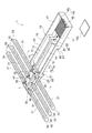
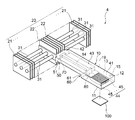
- FIG. 1 is a perspective view illustrating an outline of the heat sink according to the first embodiment of the present invention.
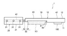
- FIG. 2 is a side view illustrating an outline of the heat sink according to the first embodiment of the present invention.
- FIG. 3 is a perspective view illustrating an outline of the inside of the heat sink according to the first embodiment of the present invention.
- FIG. 4 is an explanatory view showing an outline of a connection portion between a heat transport member of a heat sink and a pipe body according to an example of the first embodiment of the present invention.
- FIG. 5 is a side view illustrating an outline of the inside of the heat sink according to the first embodiment of the present invention.
- the heat sink 1 has a heat transport member 10 having a heat receiving portion 41 thermally connected to a heating element 100, a heat transport member 10, and heat.
- a heat-dissipating fin group 20 connected to the heat-dissipating fin group 20 and a tube 31 thermally connected to the heat-dissipating fin group 20 are provided.
- the heat radiation fin group 20 includes a plurality of first heat radiation fins 21, 21 ... Attached to the pipe body 31 and a plurality of second heat radiation fins 22, 22 ... Attached to the heat transport member 10. I have.
- the pipe body 31 is connected to the heat transport member 10 by a heat radiating portion 42 of the heat transport member 10.
- the internal space of the heat transport member 10 communicates with the internal space of the pipe body 31. That is, in the heat sink 1, the heat transport member 10 has an internal space that communicates from the heat receiving portion 41 to the connecting portion with the pipe body 31 and is an integral body in which the working fluid is sealed.
- the heat transport member 10 has a container 19 having a hollow hollow portion 13 and a working fluid (not shown) flowing through the hollow portion 13. Further, a wick structure 14 having a capillary force is housed in the cavity 13.
- the container 19 is formed by superimposing one plate-shaped body 11 located on the installation surface side of the heat sink 1 and the other plate-shaped body 12 facing the one plate-shaped body 11.
- One plate-shaped body 11 has a plate-like shape having a side wall erected from the flat surface portion at the edge of the flat surface portion.
- the other plate-shaped body 12 also has a plate-like shape having a side wall erected from the flat surface portion at the edge portion of the flat surface portion. Therefore, one plate-shaped body 11 and the other plate-shaped body 12 have a concave shape.
- the hollow portion 13 of the container 19 is formed by superimposing the one plate-shaped body 11 and the other plate-shaped body 12 in a state where the concave shapes face each other. Therefore, the shape of the container 19 is a flat type.
- the hollow portion 13 of the container 19 is an internal space sealed with respect to the external environment, and is depressurized by a degassing treatment.
- the portion to which the heating element 100 to be cooled is thermally connected functions as the heat receiving portion 41.
- the heating element 100 is cooled by being thermally connected to the container 19.
- a heat receiving portion 41 is formed at one end.
- the heat receiving portion 41 is provided with a heat receiving portion inner surface surface area increasing portion 44.
- the surface area increasing portion 44 on the inner surface of the heat receiving portion is a portion where irregularities are repeatedly formed, and in the heat sink 1, a plurality of plate-shaped fins 45, 45 ... Are erected on the inner surface of one plate-shaped body 11. There is. Since the heat receiving portion 41 is provided with the heat receiving portion inner surface surface area increasing portion 44, heat transfer from the heat receiving portion 41 to the working fluid of the liquid phase is facilitated.
- the heat transport member 10 extends in a predetermined direction from the position of the heating element 100, and a second heat radiating fin 22 forming a heat radiating fin group 20 is thermally connected to the other end facing one end. ..
- the other end of the heat transport member 10 to which the heat radiation fin group 20 is thermally connected functions as the heat dissipation portion 42 of the heat transport member 10.
- the intermediate portion located between the heat receiving portion 41 located at one end of the container 19 and the heat radiating portion 42 located at the other end of the container 19 functions as the heat insulating portion 43.
- the heat insulating portion 43 is a portion where neither the heat radiating fin group 20 nor the heating element 100 is thermally connected. The heat transferred from the heating element 100 to the heat receiving unit 41 is transported from the heat receiving unit 41 to the heat radiating unit 42 along the extending direction of the heat insulating unit 43.
- a step portion 50 on the heat dissipation side is provided between the heat insulating portion 43 and the heat radiating portion 42 of the heat transport member 10.
- the heat dissipation side step portion 50 is a portion where a step is provided in a direction not parallel to the heat transport direction of the heat transport member 10.
- the heat radiating side step portion 50 is a step in a direction substantially orthogonal to the heat transport direction of the heat transport member 10.
- the heat dissipation side step portion 50 is a step in the substantially vertical direction with respect to the installation surface of the heat sink 1.
- the heat dissipation side step portion 50 is a step toward the installation surface of the heat sink 1 from the heat insulating portion 43 toward the heat radiating portion 42.
- the prohibited area 101 exists in the installation space. Even if this is done, the heat sink 1 can be installed while avoiding the prohibited area 101.
- the heat dissipation side step portion 50 is provided on the step portion 51 which is a step in a direction substantially orthogonal to the heat transport direction of the heat transport member 10 provided on one plate-shaped body 11 and on the other plate-shaped body 12. It is formed from a step portion 52 which is a step in a direction substantially orthogonal to the heat transport direction of the heat transport member 10. Therefore, in one of the plate-shaped bodies 11, the heat insulating portion 43 and the heat radiating portion 42 are not located on the same plane. Further, also in the other plate-shaped body 12, the heat insulating portion 43 and the heat radiating portion 42 are not located on the same plane. From the above, the heat radiating portion 42 is located closer to the installation surface of the heat sink 1 than the heat insulating portion 43.
- a heat receiving side step portion 60 is provided between the heat insulating portion 43 and the heat receiving portion 41 of the heat transport member 10.
- the heat receiving side step portion 60 is a portion where a step is provided in a direction not parallel to the heat transport direction of the heat transport member 10.
- the heat receiving side step portion 60 is a step in a direction substantially orthogonal to the heat transport direction of the heat transport member 10.
- the heat receiving side step portion 60 is a step in a substantially vertical direction with respect to the installation surface of the heat sink 1.
- the heat receiving side step portion 60 is a step toward the installation surface of the heat sink 1 from the heat insulating portion 43 toward the heat receiving portion 41.
- the heat receiving side step portion 60 is formed from a step portion 61 which is a step in a direction substantially orthogonal to the heat transport direction of the heat transport member 10 provided on one plate-shaped body 11.
- the other plate-shaped body 12 is not provided with a step forming the heat receiving side step portion 60. Therefore, in one of the plate-shaped bodies 11, the heat insulating portion 43 and the heat receiving portion 41 are not located on the same plane. On the other hand, in the other plate-shaped body 12, the heat insulating portion 43 and the heat receiving portion 41 are located on the same plane.
- the dimensions of the heat transport member 10 in the width direction are not particularly limited, and in the heat sink 1, the heat receiving portion 41, the heat insulating portion 43, and the heat radiating portion 42 have substantially the same dimensions. Further, the width direction dimension of the heat transport member 10 in the heat receiving portion 41 can be appropriately selected according to the width direction dimension of the heating element 100 and the like.
- the wick structure 14 extends from the heat receiving portion 41 of the container 19 to the heat radiating portion 42 at the central portion in the width direction of the heat transport member 10. Further, the wick structure 14 has a first step portion 70 that follows the step of the heat radiation side step portion 50. That is, in the wick structure 14, the first step portion 70 is provided at a portion located between the heat insulating portion 43 and the heat radiating portion 42 of the heat transport member 10. The step of the first step portion 70 is provided in a direction that is not parallel to the heat transport direction of the heat transport member 10.
- the first step portion 70 corresponds to the step portion in the direction substantially orthogonal to the heat transport direction of the heat transport member 10, and the first step portion 70 heat transports the heat transport member 10.
- the step is approximately orthogonal to the direction.
- the first step portion 70 is substantially vertical to the installation surface of the heat sink 1 in response to the step portion 50 on the heat dissipation side being a step in the substantially vertical direction with respect to the installation surface of the heat sink 1. It is a step.
- the first step portion 70 dissipates heat from the heat insulating portion 43, corresponding to the step portion 50 on the heat radiating side being a step toward the installation surface of the heat sink 1 from the heat insulating portion 43 toward the heat radiating portion 42. There is a step toward the installation surface of the heat sink 1 toward the portion 42.
- the first step portion 70 is a step portion 71 provided on the heat insulating portion 43 side, which is a step in a direction substantially orthogonal to the heat transport direction of the heat transport member 10, and heat provided on the heat radiating portion 42 side. It is formed from a step portion 72 which is a step in a direction substantially orthogonal to the heat transport direction of the transport member 10. Therefore, in the wick structure 14, the portion located in the heat insulating portion 43 and the portion located in the heat radiating portion 42 are not located on the same plane on one plate-shaped body 11 side. Further, in the wick structure 14, even on the other plate-shaped body 12 side, the portion located in the heat insulating portion 43 and the portion located in the heat radiating portion 42 are not located on the same plane. From the above, in the wick structure 14, the portion located in the heat radiating portion 42 is located closer to the installation surface side of the heat sink 1 than the portion located in the heat insulating portion 43.
- the wick structure 14 has a second step portion 80 that follows the step of the heat receiving side step portion 60. That is, a second step portion 80 is provided at a portion located between the heat insulating portion 43 and the heat receiving portion 41 of the heat transport member 10. The step of the second step portion 80 is provided in a direction that is not parallel to the heat transport direction of the heat transport member 10. In the heat sink 1, the second step portion 80 heat transports the heat transport member 10 in response to the step portion 60 on the heat receiving side having a step in a direction substantially orthogonal to the heat transport direction of the heat transport member 10. The step is approximately orthogonal to the direction.
- the second step portion 80 is substantially vertical to the installation surface of the heat sink 1 in response to the step portion 60 on the heat receiving side being a step in the substantially vertical direction with respect to the installation surface of the heat sink 1. It is a step. Further, the second step portion 80 is a heat receiving portion from the heat insulating portion 43, corresponding to the step portion 60 on the heat receiving side being a step toward the installation surface of the heat sink 1 from the heat insulating portion 43 toward the heat receiving portion 41. There is a step toward the installation surface of the heat sink 1 toward 41.
- the second step portion 80 includes a step portion 81 provided on the heat insulating portion 43 side, which is a step in a direction substantially orthogonal to the heat transport direction of the heat transport member 10, and a heat portion 41 provided on the heat receiving portion 41 side. It is formed from a step portion 82 which is a step in a direction substantially orthogonal to the heat transport direction of the transport member 10. Therefore, in the wick structure 14, the portion located in the heat insulating portion 43 and the portion located in the heat receiving portion 41 are not located on the same plane on one plate-shaped body 11 side. Further, in the wick structure 14, even on the other plate-like body 12 side, the portion located in the heat insulating portion 43 and the portion located in the heat receiving portion 41 are not located on the same plane. From the above, in the wick structure 14, the portion located in the heat receiving portion 41 is located closer to the installation surface side of the heat sink 1 than the portion located in the heat insulating portion 43.
- the wick structure 14 is not particularly limited, and examples thereof include a sintered body of a metal powder such as copper powder, a metal mesh made of a metal wire, a groove (a plurality of fine grooves), a non-woven fabric, and a metal fiber. ..
- a metal powder sintered body is used as the wick structure 14.
- the portion of the cavity 13 where the wick structure 14 is not provided functions as a steam flow path 15 through which the working fluid of the gas phase flows.
- the steam flow path 15 extends from the heat receiving portion of the container 19 to the heat radiating portion, corresponding to the wick structure 14 extending from the heat receiving portion of the container 19 to the heat radiating portion.
- the heat transport member 10 transports the heat of the heating element 100 received by the heat receiving unit 41 from the heat receiving unit 41 to the heat radiating unit 42 due to the heat transport characteristics due to the operation of the working fluid.
- a tubular body 31 communicating with the hollow portion 13 of the container 19 and the internal space is provided at the other end of the heat transport member 10. Therefore, the working fluid flowing through the cavity 13 is sealed in the space from the cavity 13 to the inside of the tubular body 31.
- the shape of the tubular body 31 is not particularly limited, and in the heat sink 1, the shape in the longitudinal direction is linear, and the shape in the direction orthogonal to the longitudinal direction (diameter direction) is circular. Further, all the pipe bodies 31 have the same shape and dimensions.
- the tubular body 31 extends in a direction substantially orthogonal to the heat transport direction of the heat transport member 10 along the plane direction of the heat radiation portion 42 of the heat transport member 10. Therefore, the tubular body 31 is located closer to the installation surface of the heat sink 1 than the heat insulating portion 43.
- the extending direction of the tubular body 31 is not parallel to the heat transporting direction of the heat transporting member 10, so that the heat transferred from the heat transporting member 10 is transferred by the tubular body 31 in the extending direction of the heat transporting member 10. Will be transported in a different direction. Therefore, it is possible to prevent the size of the heat sink 1 from increasing in the extending direction (heat transport direction) of the heat transport member 10, so that the space of the heat sink 1 can be saved.
- a plurality of pipe bodies 31 are provided, and extend from the heat radiating portion 42 of the heat transport member 10 in a plurality of directions.
- the tubular body 31 extends in both the left and right directions, that is, in two directions, about the heat transport member 10.
- the same number of pipe bodies 31 are provided in both the left and right directions around the heat transport member 10. Since the plurality of pipe bodies 31 extend from the heat transport member 10 in a plurality of directions (two directions in the heat sink 1), the heat transported from the heat transport member 10 is the extension direction of the heat transport member 10. It is branched and transported in a plurality of different directions (two directions in the heat sink 1). Therefore, it is possible to more reliably prevent an increase in the size of the heat sink 1 in the extending direction of the heat transport member 10.
- the cavity 13 side end (hereinafter, may be referred to as “base”) 32 of the tubular body 31 is open, and the end opposite to the cavity 13 (hereinafter, may be referred to as “tip”). ) 33 is closed. Further, the hollow portion 13 of the container 19 and the internal space of the pipe body 31 communicate with each other, and the internal space of the pipe body 31 is depressurized by the degassing treatment as in the hollow portion 13. Therefore, the working fluid can flow between the hollow portion 13 of the container 19 and the internal space of the pipe body 31.
- a through hole (not shown) for attaching the pipe body 31 to the container 19 is formed on the side surface portion of the container 19.
- the shape and size of the through hole correspond to the shape and size of the pipe body 31, and the pipe body 31 is connected to the container 19 by inserting the base portion 32 of the pipe body 31 into the through hole of the container 19. ing. Therefore, the pipe body 31 and the container 19 are made of different members.
- the method of fixing the pipe body 31 attached to the container 19 is not particularly limited, and examples thereof include welding, soldering, and brazing.
- the heat sink 1 is made of a separate member from the tube 31 and the heat transport member 10, the arrangement, shape, dimensions, etc. of the tube 31 can be freely selected, and the degree of freedom in designing the heat sink 1 is improved. Further, in the heat sink 1, the tube 31 can be attached to the container 19 by inserting the tube 31 into the through hole of the container 19, so that the heat sink 1 is easy to assemble.
- another wick structure 34 that generates capillary force which is different from the wick structure 14 housed in the container 19, is provided.
- the other wick structure 34 is not particularly limited, and examples thereof include a sintered body of a metal powder such as copper powder, a metal mesh made of a metal wire, a groove, a non-woven fabric, and a metal fiber.
- a plurality of fine grooves are formed as another wick structure 34 so as to cover the entire inner surface of the tubular body 31.
- the narrow groove extends along the longitudinal direction of the tubular body 31.
- the wick structure 14 provided on the heat transport member 10 and the other wick structure 34 provided on the pipe body 31 may be connected via the connecting member 35.
- the working fluid that has undergone a phase change from the gas phase to the liquid phase inside the tube 31 is moved through the other wick structure 34 from the tip 33 of the tube 31 by the capillary force of the other wick structure 34 in the tube 31.
- the working fluid of the liquid phase that has returned to the base 32 and has returned to the base 32 of the tubular body 31 flows from the other wick structure 34 to one end of the connecting member 35.
- the liquid phase working fluid that has flowed from the other wick structure 34 to one end of the connecting member 35 flows through the connecting member 35 from one end to the other end, and the wick structure 14 of the heat transport member 10 flows from the other end of the connecting member 35. Can be refluxed to.
- the connecting member 35 improves the flow performance of the working fluid of the liquid phase between the pipe body 31 and the heat transport member 10, so that the cooling performance of the heat sink 1 is improved.
- the connecting member 35 include a wick member having a capillary force, and specific examples thereof include a metal mesh, a braided metal wire, and a metal fiber.
- Examples of the material of the container 19 and the tube 31 include copper, copper alloy, aluminum, aluminum alloy, nickel, nickel alloy, stainless steel, titanium, titanium alloy and the like.
- the working fluid to be sealed in the hollow portion 13 of the container 19 and the internal space of the pipe body 31 can be appropriately selected depending on the compatibility with the materials of the container 19 and the pipe body 31, and for example, water, fluorocarbons, and the like. Examples thereof include hydrofluoroether (HFE), cyclopentane, ethylene glycol, and mixtures thereof.
- the thickness of the container 19 can be appropriately selected from mechanical strength, weight, etc., and can be, for example, 0.5 to 3 mm, and the width of the heat transport member 10 can be, for example, 4 to 20 mm. Can be done.
- the diameter of the tubular body 31 can be appropriately selected from mechanical strength, weight, and the like, and examples thereof include 5 to 10 mm.
- the heat radiation fin group 20 is formed by arranging a plurality of first heat radiation fins 21, 21 ..., And a plurality of second heat radiation fins 22, 22 ... In parallel, respectively. ing.
- Both the first heat radiation fin 21 and the second heat radiation fin 22 are thin flat plate-shaped members.
- the first heat radiating fins 21 located on both sides of the heat radiating fin group 20 are arranged in parallel at predetermined intervals in a direction substantially parallel to the longitudinal direction of the tubular body 31. Therefore, the tubular body 31 extends along the arrangement direction of the first heat radiation fin 21.
- the first heat radiating fin 21 is attached and fixed at the position of the pipe body 31 and is thermally connected to the pipe body 31.
- the first heat radiation fins 21 all have the same shape and dimensions.
- the second heat radiating fin 22 located at the center of the heat radiating fin group 20 is attached to the position of the heat transport member 10, fixed, and thermally connected to the heat transport member 10.
- the portion of the heat transport member 10 to which the second heat radiating fin 22 is attached functions as the heat radiating portion 42.
- the second heat radiation fin 22 is attached so as to be erected on the heat transport member 10.
- the main surface of the first heat radiating fin 21 is a surface that mainly exerts the heat radiating function of the first heat radiating fin 21.
- the main surface of the second heat radiating fin 22 is a surface that mainly exerts the heat radiating function of the second heat radiating fin 22.
- the main surface of the first heat radiation fin 21 and the main surface of the second heat radiation fin 22 are arranged so as to be substantially orthogonal to the extending direction of the pipe body 31, that is, the longitudinal direction.
- the method for thermally connecting the first heat radiation fin 21 to the tube 31 is not particularly limited, and any known method can be used.
- a through hole (not shown) is provided in the first heat radiation fin 21. A method of forming a tube 31 and inserting the tube 31 into the through hole can be mentioned.
- the tube 31 is located at the installation surface side of the heat sink 1 with respect to the heat insulating portion 43, and the tube is located substantially at the center of the first heat radiation fin 21 in the height direction.
- the body 31 can be inserted and inserted. That is, the tube 31 is thermally connected at the substantially central portion in the height direction of the first heat radiation fin 21. Therefore, the heat dissipation performance of the first heat dissipation fin 21 can be improved as compared with the case where the tube 31 is fitted in the upper part of the first heat dissipation fin 21 in the height direction.
- the method of thermally connecting the second heat radiation fin 22 to the heat transport member 10 is not particularly limited, and any known method can be used.
- the heat radiation fin is attached to the end of the second heat radiation fin 22.
- the heat sink 1 is forcibly air-cooled by, for example, a blower fan (not shown).
- the cooling air F derived from the blower fan is supplied from a direction substantially parallel to the heat transport direction of the heat transport member 10. Cooling air F is supplied along the main surface of the first heat radiation fin 21 and the main surface of the second heat radiation fin 22, and the heat radiation fin group 20 is cooled.
- the material of the first heat radiating fin 21 and the second heat radiating fin 22 is not particularly limited, and for example, a metal such as copper, a copper alloy, aluminum or an aluminum alloy, a carbon material such as graphite, or a composite member using a carbon material. And so on.
- a heating element 100 which is a cooling element, is thermally connected to one end of the container 19 of the heat transport member 10, and one end is made to function as a heat receiving portion 41.
- a heating element 100 which is a cooling element, is thermally connected to one end of the container 19 of the heat transport member 10, and one end is made to function as a heat receiving portion 41.
- heat is transferred to the working fluid of the liquid phase of the cavity 13 at one end of the container 19, and the liquid phase is transferred to the working fluid of the liquid phase at one end of the container 19.
- the working fluid of is changed to the working fluid of the gas phase.
- the working fluid of the gas phase flows through the steam flow path 15 from one end of the container 19 to the other end of the heat radiating portion 42.
- the working fluid of the gas phase flows from one end of the container 19 to the other end, so that the heat transport member 10 transports heat from one end to the other end.
- a part of the gas phase working fluid flowing to the other end of the container 19 releases latent heat to change the phase to the liquid phase working fluid L, and the released latent heat is thermally connected to the heat transport member 10. It is transmitted to the second heat radiation fin 22.
- the heat transferred to the second heat radiating fins 22 is released to the external environment of the heat sink 1 via the second heat radiating fins 22.
- the wick structure 14 has a first step portion 70 that follows the step of the heat radiation side step portion 50 and a second step portion 80 that follows the step of the heat receiving side step portion 60, at the other end of the container 19.
- the working fluid L whose phase has changed to the liquid phase flows from the other end of the container 19 through the heat radiating side step portion 50 and the heat receiving side step portion 60 and returns to one end of the container 19 due to the capillary force of the wick structure 14.
- the working fluid of the gas phase that has changed phase from the working fluid of the liquid phase becomes the liquid phase at the other end of the container 19.
- the working fluid that has not undergone a phase change flows from the cavity 13 into the internal space of the tubular body 31.
- the gas phase working fluid that has flowed into the internal space of the tubular body 31 releases latent heat inside the tubular body 31 and undergoes a phase change to the liquid phase working fluid L.
- the latent heat released inside the tube 31 is transferred to the first heat radiation fin 21 that is thermally connected to the tube 31.
- the heat transferred to the first heat radiating fins 21 is released to the external environment of the heat sink 1 via the first heat radiating fins 21.
- the working fluid L which has undergone a phase change from a gas phase to a liquid phase inside the tubular body 31, is charged from the central portion and the tip portion 33 of the tubular body 31 by the capillary force of the other wick structure 34 on the inner surface of the tubular body 31. Reflux to the base 32 of 31.
- the working fluid L of the liquid phase that has returned to the base 32 of the tube 31 returns to the wick structure 14 having the first step 70 and the second step 80 at the other end of the container 19.
- the working fluid L of the liquid phase that has returned to the wick structure 14 flows from the other end of the container 19 to the heat radiating side step portion 50 and the heat receiving side step portion 60 due to the capillary force of the wick structure 14, and flows to one end of the container 19. Reflux to.
- the cavity 13 of the heat transport member 10 is integrated as a whole, unlike the internal space of the heat pipe group in which a plurality of heat pipes are arranged in parallel. Therefore, in the heat sink 1, the heat transport member 10 integrated with the cavity 13 transports the heat of the heating element 100 from the heat receiving portion 41 to the connecting portion between the heat radiating fin group 20 and the tubular body 31 thermally connected.
- the liquid phase working fluid has excellent recirculation characteristics, and even if the amount of heat generated from the heating element 100 increases, the heat input in the heat receiving unit 41 can be made uniform, and the thermal resistance in the heat receiving unit 41 can be reduced.
- the heat radiating portion 42 is located closer to the installation surface side of the heat sink 1 than the heat insulating portion 43 by providing the heat radiating side step portion 50 between the heat radiating portion 43 and the heat radiating portion 42 of the heat transport member 10. Further, a wick structure 14 having a first step portion 70 extending from the heat receiving portion 41 to the heat radiating portion 42 and following the step of the heat radiating side step portion 50 is housed in the heat transport member 10. Therefore, in an environment where the installation space of the heat sink 1, particularly the installation space in the height direction of the heat sink 1, is limited, even if the prohibited area 101 exists in the installation space, the heat receiving unit 41 can avoid the prohibited area 101.
- the entire heating element 100 can be uniformly cooled even if the heating element 100 has uneven heat generation.
- the heat transport member 10 has the heat receiving side step portion 60, so that the prohibited area 100 of the installation space can be more reliably avoided. Further, since the wick structure 14 has the second step portion 80 that follows the step of the heat receiving side step portion 60, the return of the working fluid of the liquid phase from the heat radiating portion 42 to the heat receiving portion 41 is further facilitated. ..
- FIG. 6 is a plan view illustrating an outline of the heat sink according to the second embodiment of the present invention.
- FIG. 7 is a side view illustrating an outline of the heat sink according to the second embodiment of the present invention.
- the tubular body extends in a direction substantially orthogonal to the heat transport direction of the flat heat transport member along the plane direction of the flat heat transport member.
- the tubular body 31 is substantially orthogonal to the planar direction of the planar heat transport member 10 and is planar. It extends in a direction substantially orthogonal to the heat transport direction of the mold heat transport member 10.
- the heat radiation fin group 20 is formed of a plurality of first heat radiation fins 21, 21, ... Attached to the tube body 31.
- the first heat radiation fins 21 are arranged in parallel at predetermined intervals in a direction substantially parallel to the longitudinal direction of the tubular body 31. Therefore, the tubular body 31 extends along the arrangement direction of the first heat radiation fin 21.
- the heat dissipation side step portion 50 is a step toward the installation surface of the heat sink 2 from the heat insulating portion 43 toward the heat radiating portion 42. Therefore, since the number of the first heat radiating fins 21 installed can be increased, the heat radiating performance of the heat radiating fins group 20 is improved.
- the heat sink 2 has an installation space in the height direction of the heat sink 2, but the installation space is limited in the width direction of the heat sink 2. Even if the prohibited area 101 exists in the installation space, the prohibited area 101 is provided. While avoiding this, it is possible to reliably prevent the heat receiving portion 41 from drying out and improve the heat radiating performance of the heat radiating fin group 20 thermally connected to the heat radiating portion 42 of the heat transport member 10.
- FIG. 8 is a perspective view illustrating an outline of the inside of the heat sink according to the third embodiment of the present invention.
- the wick structure 14 extending from the heat receiving portion 41 of the container 19 to the heat radiating portion 42 at the central portion in the width direction of the heat transport member 10 , It is branched between the heat receiving unit 41 and the heat radiating unit 42.
- the wick structure 14 has a branch portion near the heat radiating portion 42 side of the second step portion 80, and the length of the wick structure 14 is provided on both sides of the container 19 of the heat transport member 10 in the width direction.
- Two branch wick portions 14-1 and 14-2 extend along the direction.
- the wick structure 14 extends from the heat receiving portion 41 to the heat radiating portion 42, and the branched wick portions 14-1 and 14-2 are second, respectively, substantially parallel to the wick structure 14 at predetermined intervals. It extends from a portion of the step portion 80 near the heat radiating portion 42 side to the heat radiating portion 42. Therefore, the branch wick portions 14-1 and 14-2 each have a step portion corresponding to the step of the heat dissipation side step portion 50, similarly to the wick structure 14.
- the other wick structure 34 provided in the pipe body 31 is connected to the wick structure 14 and the branch wick portion 14-1 or the branch wick portion 14-2 via the connecting member 35. Therefore, the working fluid of the liquid phase inside the tubular body 31 returns from the other wick structure 34 to the wick structure 14 and the branch wick portions 14-1 and 14-2 via the connecting member 35.
- the wick structure 14 has a first step portion 70 corresponding to the step of the heat dissipation side step portion 50, but also the branch wick portions 14-1 and 14-2 also have the heat dissipation side step portion 50, respectively.
- the working fluid of the liquid phase can be more smoothly returned from the pipe body 31 and the heat radiating portion 42 to the heat receiving portion 41. Therefore, in the heat sink 3, even if the heat receiving portion 41 is installed in the top heat posture in which the heat receiving portion 41 is located above the heat radiating portion 42 in the gravity direction, the working fluid of the liquid phase receives heat from the tube 31 and the radiating portion 42 more reliably. It can be returned to the unit 41, and the dryout of the heat receiving unit 41 can be prevented more reliably.
- FIG. 9 is a perspective view illustrating an outline of the heat sink according to the fourth embodiment of the present invention.
- the heat-dissipating side step portion is a step portion that is a step portion in a direction substantially orthogonal to the heat transport direction of the heat transport member provided on one plate-shaped body, and the other plate shape. It was formed from a step portion which is a step in a direction substantially orthogonal to the heat transport direction of the heat transport member provided on the body.
- the heat dissipation side step portion 50 is relative to the heat transport direction of the heat transport member 10 provided on one plate-shaped body 11.
- the other plate-shaped body 12 is not provided with a step portion in a direction substantially orthogonal to the heat transport direction of the heat transport member 10. Therefore, in one of the plate-shaped bodies 11, the heat insulating portion 43 and the heat radiating portion 42 are not located on the same plane. On the other hand, in the other plate-shaped body 12, the heat insulating portion 43 and the heat radiating portion 42 are located on the same plane. From the above, the thickness of the container 19 in the heat radiating portion 42 is thicker than the thickness of the container 19 in the heat radiating portion 43 by the size of the stepped portion 50 on the heat radiating side.
- the thickness of the heat radiating portion 42 of the heat sink 4 according to the fourth embodiment is thicker than the thickness of the heat radiating portion of the heat sink according to the first embodiment described above. Further, the internal space of the container 19 in the heat radiating side step portion 50 of the heat sink 4 according to the fourth embodiment is wider than the internal space of the container in the heat radiating side step portion of the heat sink according to the first embodiment described above. There is.
- the wick structure 14 extends from the heat receiving portion 41 of the heat transport member 10 to the heat radiating portion 42. Further, the wick structure 14 has a first step portion 70 that follows the step of the heat dissipation side step portion 50 and a second step portion 80 that follows the step of the heat receiving side step portion 60.
- the heat radiating side step portion 50 since the internal space of the container 19 in the heat radiating side step portion 50 is wide, even if the heat radiating side step portion 50 is provided between the heat insulating portion 43 and the heat radiating portion 42 of the heat transport member 10.
- the working fluid of the liquid phase can smoothly return the first step portion 70 from the heat radiating portion 42 toward the heat receiving portion 41.
- the heat transport member 10 is connected to the tube 31 in which the cavity 13 of the container 19 and the internal space communicate with each other, and the first heat radiation fin of the heat radiation fin group 20 is connected to the tube 31.
- the pipe 31 may not be connected to the heat transport member 10, and therefore the heat radiating fin group 20 may not be provided with the first heat radiating fin 21.
- the first step portion 70 of the wick structure 14 is, if necessary, in a direction orthogonal to the heat transport direction of the heat transport member 10 with respect to the wick structure 14 at the positions of the heat insulating portion 43 and the heat radiating portion 42.
- the width of the first step portion 70 may be wider than the width of the wick structure 14 located in the heat insulating portion 43 and the heat radiating portion 42. Since the width of the first step portion 70 is widened, the working fluid of the liquid phase can be more smoothly returned from the heat radiating portion 42 to the heat insulating portion 43.
- the second step portion 80 of the wick structure 14 is widened in the width direction of the heat transport member 10 with respect to the wick structure 14 at the positions of the heat insulating portion 43 and the heat receiving portion 41, if necessary. It may have a part 83 (see FIGS. 1 and 3). Since the width of the second step portion 80 is widened, the working fluid of the liquid phase can be more smoothly returned from the heat insulating portion 43 to the heat receiving portion 41.
- the heat receiving side step portion 60 is formed on the heat transport member 10, but the heat receiving side step portion 60 may not be provided depending on the usage condition and the installation condition of the heat sink.
- the heat sink of the present invention has excellent cooling performance even if a prohibited area exists in the installation space in an environment where the installation space of the heat sink is limited. Therefore, for example, the heat sink is mounted on a circuit board installed in a narrow space. It has high utility value in the field of cooling electronic components with a high calorific value, for example, electronic components such as central processing units.
- Heat transport member 14
- Wick structure 20
- Heat dissipation fin group 31
- Tube body 41
- Heat receiving part 42
- Heat dissipation part 43
- Insulation part 50
Landscapes
- Engineering & Computer Science (AREA)
- Physics & Mathematics (AREA)
- Thermal Sciences (AREA)
- Mechanical Engineering (AREA)
- General Engineering & Computer Science (AREA)
- Life Sciences & Earth Sciences (AREA)
- Sustainable Development (AREA)
- Microelectronics & Electronic Packaging (AREA)
- Geometry (AREA)
- Cooling Or The Like Of Semiconductors Or Solid State Devices (AREA)
- Cooling Or The Like Of Electrical Apparatus (AREA)
Abstract
本発明は、ヒートシンクの設置スペースが制限される環境下、該設置スペースに禁止領域が存在していても、受熱部のドライアウトを防止しつつ放熱フィンの放熱性能を向上させることができ、また、受熱部における入熱を均一化できるヒートシンクを提供する。 発熱体と熱的に接続される受熱部を有する熱輸送部材と、該熱輸送部材の放熱部にて接続された、複数の放熱フィンが配置された放熱フィン群と、を備えたヒートシンクであり、前記熱輸送部材が、前記受熱部から前記放熱部まで連通し、且つ作動流体が封入された一体である内部空間を有し、前記熱輸送部材の内部空間に、前記受熱部から前記放熱部へ延在したウィック構造体が収納され、前記熱輸送部材が、前記受熱部と前記放熱部の間に位置する断熱部と前記放熱部との間に、前記熱輸送部材の熱輸送方向に対して平行方向ではない方向に段差が設けられた放熱側段差部を有し、前記放熱部が前記断熱部よりも前記ヒートシンクの設置面側に位置するヒートシンク。
Description
本発明は、電子回路基板等の基板に搭載された電気・電子部品等の発熱体を冷却するヒートシンクに関し、特に、基板の狭小空間に禁止領域が存在していても、発熱体を冷却できるヒートシンクに関する。
電子機器の高機能化に伴い、電子機器内部には、電子部品等の発熱体を含め、多数の部品が電子回路基板等の基板上に高密度に搭載されている。また、電子機器の高機能化に伴い、電子部品等の発熱体の発熱量が増大している。電子部品等の発熱体を冷却する手段として、ヒートシンクが使用されることがある。ヒートシンクとして、一般的には、管形状のヒートパイプを備えたヒートパイプ式のヒートシンクが使用される。
ヒートパイプ式ヒートシンクとしては、例えば、複数設けられた管形状のヒートパイプの外周面に突出して平板状の多数の放熱フィンが設けられたヒートパイプ式ヒートシンクがある(特許文献1)。特許文献1のヒートシンクは、複数の管形状のヒートパイプによって発熱体の熱を放熱フィンへ輸送し、該放熱フィンから放熱させるように構成されたヒートシンクである。
一方で、近年、電子機器内部には、電子部品等の発熱体を含め、多数の部品がますます高密度に搭載されているので、基板上におけるヒートシンクの設置スペースが狭小空間に制限されることがある。また、電子部品等の高機能化により電子部品からの発熱量が増大していることから、ヒートシンクには、省スペース化と冷却性能のさらなる向上が要求されている。
特許文献1のヒートシンク等、発熱体の熱を複数のヒートパイプによって放熱フィンへ輸送するヒートシンクでは、冷却性能を向上させるために、多数のヒートパイプを並列配置させたヒートパイプ群を形成し、該ヒートパイプ群を発熱体に熱的に接続することが必要となる。しかし、多数のヒートパイプからなるヒートパイプ群を発熱体に熱的に接続すると、発熱体からの距離によってヒートパイプの受熱量が異なるので、各ヒートパイプの受熱を均一化できず、十分な冷却性能が得られない場合があった。また、各ヒートパイプの外周面にはR部があり、R部外側に生じる空隙はヒートパイプ群の熱輸送に寄与しないので、ヒートパイプ群の受熱部の体積が十分に得られず、やはり、十分な冷却性能が得られない場合があった。
また、基板上には、多数の部品が高密度に搭載されているので、ヒートシンクの設置スペースに、他の部品等が取り付けられた禁止領域が存在することがある。基板上の禁止領域を回避するためにヒートパイプ群の断熱部と放熱部を基板から離れた方向へ逃がすと、狭小空間の設置スペースでは、ヒートパイプ群が放熱フィンの中央部にて熱的に接続されることができず、放熱フィンの放熱性能が十分得られない場合があった。また、ヒートパイプ群の断熱部と放熱部を基板から離れた方向へ逃がすと、狭小空間の設置スペースでは、放熱フィンの設置枚数が制約されて、やはり、放熱フィンの放熱性能が十分得られない場合があった。
一方で、放熱フィンの放熱性能を得るために、ヒートパイプ群の放熱部は基板から離れた方向へ逃がさずに、断熱部のみを基板から離れた方向へ逃がすと、ヒートパイプ群の放熱部が受熱部よりも重力方向下方となるトップヒートの姿勢になる。ヒートパイプ群がトップヒートの姿勢になると、放熱部にて気相から液相へ相変化した作動流体の受熱部への還流が阻害されて、受熱部にドライアウトが生じてしまうことがあった。
上記事情に鑑み、本発明は、ヒートシンクの設置スペースが制限される環境下、該設置スペースに禁止領域が存在していても、受熱部のドライアウトを防止しつつ放熱フィン群の放熱性能を向上させることができ、また、受熱部における入熱を均一化できるヒートシンクを提供することを目的とする。
本発明のヒートシンクの構成の要旨は、以下の通りである。
[1]発熱体と熱的に接続される受熱部を有する熱輸送部材と、該熱輸送部材の放熱部にて接続された、複数の放熱フィンが配置された放熱フィン群と、を備えたヒートシンクであり、
前記熱輸送部材が、前記受熱部から前記放熱部まで連通し、且つ作動流体が封入された一体である内部空間を有し、
前記熱輸送部材の内部空間に、前記受熱部から前記放熱部へ延在したウィック構造体が収納され、
前記熱輸送部材が、前記受熱部と前記放熱部の間に位置する断熱部と前記放熱部との間に、前記熱輸送部材の熱輸送方向に対して平行方向ではない方向に段差が設けられた放熱側段差部を有し、前記放熱部が前記断熱部よりも前記ヒートシンクの設置面側に位置するヒートシンク。
[2]前記発熱体と熱的に接続される前記受熱部を有する熱輸送部材と、該熱輸送部材の放熱部にて接続された管体と、該管体と熱的に接続された、前記複数の放熱フィンが配置された放熱フィン群と、を備えたヒートシンクであり、
前記熱輸送部材が、前記受熱部から前記管体との接続部まで連通し、且つ前記作動流体が封入された一体である内部空間を有し、前記熱輸送部材の内部空間が、前記管体の内部空間と連通し、
前記熱輸送部材の内部空間に、前記受熱部から前記放熱部へ延在した前記ウィック構造体が収納され、
前記熱輸送部材が、前記受熱部と前記放熱部の間に位置する前記断熱部と前記放熱部との間に、前記熱輸送部材の熱輸送方向に対して平行方向ではない方向に段差が設けられた前記放熱側段差部を有し、前記放熱部が前記断熱部よりも前記ヒートシンクの設置面側に位置する[1]に記載のヒートシンク。
[3]前記ウィック構造体が、前記放熱側段差部の段差に追従した第1の段差部を有する[1]または[2]に記載のヒートシンク。
[4]前記熱輸送部材が、前記受熱部と前記断熱部との間に、前記熱輸送部材の熱輸送方向に対して平行方向ではない方向に段差が設けられた受熱側段差部を、さらに有する[1]乃至[3]のいずれか1つに記載のヒートシンク。
[5]前記ウィック構造体が、前記受熱側段差部の段差に追従した第2の段差部を、さらに有する[4]に記載のヒートシンク。
[6]前記第1の段差部における前記ウィック構造体が、前記断熱部及び前記放熱部の位置における前記ウィック構造体よりも、前記熱輸送部材の熱輸送方向に対して直交方向に拡幅されている[3]乃至[5]のいずれか1つに記載のヒートシンク。
[7]前記管体が、前記放熱フィンの配置方向に沿って延在している[2]に記載のヒートシンク。
[8]前記管体の延在方向が、前記熱輸送部材の熱輸送方向と平行ではない[2]に記載のヒートシンク。
[9]前記管体が、複数設けられ、前記熱輸送部材から複数の方向に延在している[2]に記載のヒートシンク。
[10]前記熱輸送部材の少なくとも一面が、平面形状である[1]乃至[9]のいずれか1つに記載のヒートシンク。
[1]発熱体と熱的に接続される受熱部を有する熱輸送部材と、該熱輸送部材の放熱部にて接続された、複数の放熱フィンが配置された放熱フィン群と、を備えたヒートシンクであり、
前記熱輸送部材が、前記受熱部から前記放熱部まで連通し、且つ作動流体が封入された一体である内部空間を有し、
前記熱輸送部材の内部空間に、前記受熱部から前記放熱部へ延在したウィック構造体が収納され、
前記熱輸送部材が、前記受熱部と前記放熱部の間に位置する断熱部と前記放熱部との間に、前記熱輸送部材の熱輸送方向に対して平行方向ではない方向に段差が設けられた放熱側段差部を有し、前記放熱部が前記断熱部よりも前記ヒートシンクの設置面側に位置するヒートシンク。
[2]前記発熱体と熱的に接続される前記受熱部を有する熱輸送部材と、該熱輸送部材の放熱部にて接続された管体と、該管体と熱的に接続された、前記複数の放熱フィンが配置された放熱フィン群と、を備えたヒートシンクであり、
前記熱輸送部材が、前記受熱部から前記管体との接続部まで連通し、且つ前記作動流体が封入された一体である内部空間を有し、前記熱輸送部材の内部空間が、前記管体の内部空間と連通し、
前記熱輸送部材の内部空間に、前記受熱部から前記放熱部へ延在した前記ウィック構造体が収納され、
前記熱輸送部材が、前記受熱部と前記放熱部の間に位置する前記断熱部と前記放熱部との間に、前記熱輸送部材の熱輸送方向に対して平行方向ではない方向に段差が設けられた前記放熱側段差部を有し、前記放熱部が前記断熱部よりも前記ヒートシンクの設置面側に位置する[1]に記載のヒートシンク。
[3]前記ウィック構造体が、前記放熱側段差部の段差に追従した第1の段差部を有する[1]または[2]に記載のヒートシンク。
[4]前記熱輸送部材が、前記受熱部と前記断熱部との間に、前記熱輸送部材の熱輸送方向に対して平行方向ではない方向に段差が設けられた受熱側段差部を、さらに有する[1]乃至[3]のいずれか1つに記載のヒートシンク。
[5]前記ウィック構造体が、前記受熱側段差部の段差に追従した第2の段差部を、さらに有する[4]に記載のヒートシンク。
[6]前記第1の段差部における前記ウィック構造体が、前記断熱部及び前記放熱部の位置における前記ウィック構造体よりも、前記熱輸送部材の熱輸送方向に対して直交方向に拡幅されている[3]乃至[5]のいずれか1つに記載のヒートシンク。
[7]前記管体が、前記放熱フィンの配置方向に沿って延在している[2]に記載のヒートシンク。
[8]前記管体の延在方向が、前記熱輸送部材の熱輸送方向と平行ではない[2]に記載のヒートシンク。
[9]前記管体が、複数設けられ、前記熱輸送部材から複数の方向に延在している[2]に記載のヒートシンク。
[10]前記熱輸送部材の少なくとも一面が、平面形状である[1]乃至[9]のいずれか1つに記載のヒートシンク。
上記態様では、熱輸送部材のうち、冷却対象である発熱体と熱的に接続される部位が受熱部として機能し、管体と接続された部位が熱輸送部材の放熱部として機能する。熱輸送部材の受熱部では、作動流体が発熱体から受熱して液相から気相へ相変化し、熱輸送部材の放熱部では、気相の作動流体の一部が潜熱を放出して気相から液相へ相変化する。本発明のヒートシンクの態様では、発熱体の熱は、熱輸送部材によって熱輸送部材の受熱部から熱輸送部材の放熱部まで輸送され、さらには、熱輸送部材の放熱部から管体まで輸送される。また、熱輸送部材が発熱体から受熱することで気相に相変化した作動流体は、熱輸送部材から管体へ流通する。気相の作動流体が熱輸送部材から管体へ流通することで、管体は、熱輸送部材から熱を受け、さらに、熱輸送部材から受けた熱を放熱フィン群へ伝達する。管体が熱輸送部材から受けた熱を放熱フィン群へ伝達する際に、熱輸送部材から管体へ流通した気相の作動流体は液相へ相変化する。管体から放熱フィン群へ伝達された熱は、放熱フィン群からヒートシンクの外部環境へ放出される。また、上記態様では、熱輸送部材が、断熱部と放熱部との間に、熱輸送方向に対して平行方向ではない方向に段差が設けられた放熱側段差部を有し、放熱部が断熱部よりもヒートシンクの設置面側に位置するので、放熱部は断熱部と同一平面上には位置していない。
本発明のヒートシンクの態様では、受熱部を有する熱輸送部材の内部空間は、複数のヒートパイプが並列配置されたヒートパイプ群の内部空間とは異なり、全体が連通して一体となっている。よって、内部空間が一体である熱輸送部材が発熱体の熱を受熱部から放熱フィンと熱的に接続された管体との接続部まで輸送する本発明のヒートシンクの態様によれば、液相の作動流体の還流特性に優れ、また、発熱体からの発熱量が増大しても、受熱部における入熱を均一化でき、受熱部における熱抵抗を低減できる。また、本発明のヒートシンクの態様によれば、熱輸送部材の内部空間には受熱部から放熱部へ延在したウィック構造体が収納されており、また、熱輸送部材の断熱部と放熱部との間に、熱輸送方向に対して平行方向ではない方向に段差が設けられた放熱側段差部を備えることで、放熱部が断熱部よりもヒートシンクの設置面側に位置している。従って、ヒートシンクの設置スペースが制限される環境下、該設置スペースに禁止領域が存在していても、受熱部のドライアウトを防止しつつ、熱輸送部材の放熱部と熱的に接続される放熱フィン群の放熱性能を向上させることができる。また、本発明のヒートシンクの態様によれば、熱輸送部材の内部空間は全体が連通して一体となっているので、発熱体に発熱ムラが生じていても、発熱体全体を均一に冷却できる。
本発明のヒートシンクの態様によれば、ウィック構造体が放熱側段差部の段差に追従した第1の段差部を有することにより、放熱部から受熱部への液相の作動流体の還流がさらに円滑化されて、受熱部のドライアウトをより確実に防止できる。
本発明のヒートシンクの態様によれば、熱輸送部材が、受熱部と断熱部との間に熱熱輸送部材の熱輸送方向に対して平行方向ではない方向に段差が設けられた受熱側段差部をさらに有することにより、設置スペースの禁止領域をより確実に回避できる。
本発明のヒートシンクの態様によれば、ウィック構造体が受熱側段差部の段差に追従した第2の段差部をさらに有することにより、設置スペースの禁止領域をより確実に回避しつつ、放熱部から受熱部への液相の作動流体の還流がさらに円滑化される。
本発明のヒートシンクの態様によれば、ウィック構造体が第1の段差部にて熱輸送部材の熱輸送方向に対して直交方向に拡幅されていることにより、液相の作動流体が放熱部から断熱部へより円滑に還流できる。
本発明のヒートシンクの態様によれば、熱輸送部材の内部空間と連通した管体が放熱フィンの配置方向に沿って延在していることにより、気相の作動流体が、管体内部を放熱フィンの配置方向に沿って流通する。従って、放熱フィン群の放熱効率が向上して、ヒートシンクの冷却性能が確実に向上する。
本発明のヒートシンクの態様によれば、管体の延在方向が熱輸送部材の熱輸送方向と平行ではないことにより、熱輸送部材から輸送された熱は熱輸送部材の延在方向(熱輸送方向)とは異なる方向へ輸送される。従って、熱輸送部材の延在方向(熱輸送方向)について、ヒートシンクの寸法の増大を防止することができ、結果、省スペース化を図ることができる。
本発明のヒートシンクの態様によれば、複数の管体が熱輸送部材から複数の方向に延在していることにより、熱輸送部材から管体へ輸送された熱は熱輸送部材の延在方向(熱輸送方向)とは異なる複数の方向へ輸送される。従って、熱輸送部材の延在方向(熱輸送方向)について、ヒートシンクの寸法の増大をより確実に防止することができる。
以下に、本発明の実施形態例に係るヒートシンクについて、図面を用いながら説明する。まず、本発明の第1実施形態例に係るヒートシンクについて説明する。なお、図1は本発明の第1実施形態例に係るヒートシンクの概要を説明する斜視図である。図2は、本発明の第1実施形態例に係るヒートシンクの概要を説明する側面図である。図3は、本発明の第1実施形態例に係るヒートシンク内部の概要を説明する斜視図である。図4は、本発明の第1実施形態例に係るヒートシンクの熱輸送部材と管体の接続部の概要を示す説明図である。図5は、本発明の第1実施形態例に係るヒートシンク内部の概要を説明する側面図である。
図1、2に示すように、本発明の第1実施形態例に係るヒートシンク1は、発熱体100と熱的に接続される受熱部41を有する熱輸送部材10と、熱輸送部材10と熱的に接続された放熱フィン群20と、放熱フィン群20と熱的に接続された管体31と、を備えている。放熱フィン群20は、管体31に取り付けられた複数の第1の放熱フィン21、21・・・と、熱輸送部材10に取り付けられた複数の第2の放熱フィン22、22・・・を備えている。管体31は、熱輸送部材10とは、熱輸送部材10の放熱部42にて接続されている。また、熱輸送部材10の内部空間が、管体31の内部空間と連通している。すなわち、ヒートシンク1では、熱輸送部材10は、受熱部41から管体31との接続部まで連通し且つ作動流体が封入された一体である内部空間を有している。
図1、2に示すように、熱輸送部材10は、中空の空洞部13を有するコンテナ19と、空洞部13を流通する作動流体(図示せず)とを有している。また、空洞部13内には、毛細管力を有するウィック構造体14が収納されている。コンテナ19は、ヒートシンク1の設置面側に位置する一方の板状体11と一方の板状体11と対向する他方の板状体12とを重ね合わせることにより形成されている。
一方の板状体11は平面部の縁部に平面部から立設した側壁を有する板状である。他方の板状体12も、平面部の縁部に平面部から立設した側壁を有する板状である。従って、一方の板状体11と他方の板状体12は、凹形状となっている。一方の板状体11と他方の板状体12とを凹形状を対向させた状態で重ね合わせることにより、コンテナ19の空洞部13が形成される。従って、コンテナ19の形状は平面型である。コンテナ19の空洞部13は、外部環境に対して密閉された内部空間であり、脱気処理により減圧されている。
コンテナ19外面のうち、冷却対象である発熱体100が熱的に接続される部位が受熱部41として機能する。発熱体100がコンテナ19に熱的に接続されることで、発熱体100が冷却される。熱輸送部材10では、一方端に発熱体100が熱的に接続されているので、一方端に受熱部41が形成されている。また、コンテナ19内面のうち、受熱部41には、受熱部内面表面積増大部44が設けられている。受熱部内面表面積増大部44は、凹凸が繰り返し形成された部位であり、ヒートシンク1では、複数の板状フィン45、45・・・が、一方の板状体11の内面上に立設されている。受熱部41に受熱部内面表面積増大部44が設けられていることにより、受熱部41から液相の作動流体への熱伝達が円滑化される。
熱輸送部材10は、発熱体100の位置から所定方向へ延在しており、一方端に対向する他方端に放熱フィン群20を形成する第2の放熱フィン22が熱的に接続されている。放熱フィン群20が熱的に接続されている熱輸送部材10の他方端が、熱輸送部材10の放熱部42として機能する。
熱輸送部材10は、コンテナ19の一方端に位置する受熱部41とコンテナ19の他方端に位置する放熱部42との間に位置する中間部が、断熱部43として機能する。断熱部43は、放熱フィン群20も発熱体100も熱的に接続されていない部位である。発熱体100から受熱部41へ伝達された熱が、断熱部43の延在方向に沿って、受熱部41から放熱部42へ輸送される。
熱輸送部材10の断熱部43と放熱部42との間には、放熱側段差部50が設けられている。放熱側段差部50は、熱輸送部材10の熱輸送方向に対して平行方向ではない方向に段差が設けられている部位である。ヒートシンク1では、放熱側段差部50は、熱輸送部材10の熱輸送方向に対して略直交方向の段差となっている。また、放熱側段差部50は、ヒートシンク1の設置面に対して略鉛直方向の段差となっている。さらに、放熱側段差部50は、断熱部43から放熱部42へ向かってヒートシンク1の設置面方向への段差となっている。熱輸送部材10の断熱部43と放熱部42との間に放熱側段差部50が設けられていることにより、ヒートシンク1の設置スペースが制限される環境下、該設置スペースに禁止領域101が存在していても、禁止領域101を回避してヒートシンク1を設置することができる。
放熱側段差部50は、一方の板状体11に設けられた熱輸送部材10の熱輸送方向に対して略直交方向の段差である段差部51と、他方の板状体12に設けられた熱輸送部材10の熱輸送方向に対して略直交方向の段差である段差部52とから形成されている。従って、一方の板状体11においては、断熱部43と放熱部42は同一平面上に位置していない。また、他方の板状体12においても、断熱部43と放熱部42は同一平面上に位置していない。上記から、放熱部42が断熱部43よりもヒートシンク1の設置面側に位置している。
また、図1、2に示すように、ヒートシンク1では、熱輸送部材10の断熱部43と受熱部41との間には、受熱側段差部60が設けられている。受熱側段差部60は、熱輸送部材10の熱輸送方向に対して平行方向ではない方向に段差が設けられている部位である。ヒートシンク1では、受熱側段差部60は、熱輸送部材10の熱輸送方向に対して略直交方向の段差となっている。また、受熱側段差部60は、ヒートシンク1の設置面に対して略鉛直方向の段差となっている。さらに、受熱側段差部60は、断熱部43から受熱部41へ向かってヒートシンク1の設置面方向への段差となっている。
受熱側段差部60は、一方の板状体11に設けられた熱輸送部材10の熱輸送方向に対して略直交方向の段差である段差部61から形成されている。他方の板状体12には、受熱側段差部60を形成する段差は設けられていない。従って、一方の板状体11においては、断熱部43と受熱部41は同一平面上に位置していない。一方で、他方の板状体12においては、断熱部43と受熱部41は同一平面上に位置している。
熱輸送部材10の幅方向の寸法は、特に限定されず、ヒートシンク1では、受熱部41、断熱部43及び放熱部42は、略同じ寸法となっている。また、受熱部41における熱輸送部材10の幅方向の寸法は、発熱体100の幅方向の寸法等に応じて適宜選択可能である。
図1、3に示すように、ウィック構造体14は、熱輸送部材10の幅方向中央部にてコンテナ19の受熱部41から放熱部42まで延在している。また、ウィック構造体14は、放熱側段差部50の段差に追従した第1の段差部70を有する。すなわち、ウィック構造体14のうち、熱輸送部材10の断熱部43と放熱部42との間に位置する部位に、第1の段差部70が設けられている。第1の段差部70の段差は、熱輸送部材10の熱輸送方向に対して平行方向ではない方向に設けられている。ヒートシンク1では、放熱側段差部50が熱輸送部材10の熱輸送方向に対して略直交方向の段差となっていることに対応して、第1の段差部70は熱輸送部材10の熱輸送方向に対して略直交方向の段差となっている。また、放熱側段差部50がヒートシンク1の設置面に対して略鉛直方向の段差となっていることに対応して、第1の段差部70はヒートシンク1の設置面に対して略鉛直方向の段差となっている。さらに、放熱側段差部50は、断熱部43から放熱部42へ向かってヒートシンク1の設置面方向への段差となっていることに対応して、第1の段差部70は断熱部43から放熱部42へ向かってヒートシンク1の設置面方向への段差となっている。
第1の段差部70は、断熱部43側に設けられた、熱輸送部材10の熱輸送方向に対して略直交方向の段差である段差部71と、放熱部42側に設けられた、熱輸送部材10の熱輸送方向に対して略直交方向の段差である段差部72とから形成されている。従って、ウィック構造体14は、一方の板状体11側においては、断熱部43に位置する部位と放熱部42に位置する部位は同一平面上に位置していない。また、ウィック構造体14は、他方の板状体12側においても、断熱部43に位置する部位と放熱部42に位置する部位は同一平面上に位置していない。上記から、ウィック構造体14は、放熱部42に位置する部位が断熱部43に位置する部位よりもヒートシンク1の設置面側に位置している。
また、図1、3に示すように、ウィック構造体14は、受熱側段差部60の段差に追従した第2の段差部80を有する。すなわち、熱輸送部材10の断熱部43と受熱部41との間に位置する部位に、第2の段差部80が設けられている。第2の段差部80の段差は、熱輸送部材10の熱輸送方向に対して平行方向ではない方向に設けられている。ヒートシンク1では、受熱側段差部60が熱輸送部材10の熱輸送方向に対して略直交方向の段差となっていることに対応して、第2の段差部80は熱輸送部材10の熱輸送方向に対して略直交方向の段差となっている。また、受熱側段差部60がヒートシンク1の設置面に対して略鉛直方向の段差となっていることに対応して、第2の段差部80はヒートシンク1の設置面に対して略鉛直方向の段差となっている。さらに、受熱側段差部60が断熱部43から受熱部41へ向かってヒートシンク1の設置面方向への段差となっていることに対応して、第2の段差部80は断熱部43から受熱部41へ向かってヒートシンク1の設置面方向への段差となっている。
第2の段差部80は、断熱部43側に設けられた、熱輸送部材10の熱輸送方向に対して略直交方向の段差である段差部81と、受熱部41側に設けられた、熱輸送部材10の熱輸送方向に対して略直交方向の段差である段差部82とから形成されている。従って、ウィック構造体14は、一方の板状体11側においては、断熱部43に位置する部位と受熱部41に位置する部位は同一平面上に位置していない。また、ウィック構造体14は、他方の板状体12側においても、断熱部43に位置する部位と受熱部41に位置する部位は同一平面上に位置していない。上記から、ウィック構造体14は、受熱部41に位置する部位が断熱部43に位置する部位よりもヒートシンク1の設置面側に位置している。
ウィック構造体14としては、特に限定されないが、例えば、銅粉等の金属粉の焼結体、金属線からなる金属メッシュ、グルーブ(複数の細溝)、不織布、金属繊維等を挙げることができる。熱輸送部材10では、ウィック構造体14として、金属粉の焼結体が用いられている。空洞部13のうち、ウィック構造体14の設けられていない部位が、気相の作動流体の流通する蒸気流路15として機能する。蒸気流路15は、ウィック構造体14がコンテナ19の受熱部から放熱部まで延在していることに対応して、コンテナ19の受熱部から放熱部まで延在している。熱輸送部材10は、作動流体の動作による熱輸送特性によって、受熱部41にて受けた発熱体100の熱を受熱部41から放熱部42へ輸送する。
図1~3に示すように、熱輸送部材10の他方端には、コンテナ19の空洞部13と内部空間の連通した管体31が設けられている。従って、空洞部13を流通する作動流体は、空洞部13から管体31内部までの空間に封入されている。管体31の形状は、特に限定されず、ヒートシンク1では、長手方向の形状は直線状であり、長手方向に対して直交方向(径方向)の形状は円形状となっている。また、いずれの管体31も、形状、寸法は同じとなっている。
管体31は、熱輸送部材10の放熱部42の平面方向に沿って、熱輸送部材10の熱輸送方向に対して略直交方向に延在している。従って、管体31は、断熱部43よりもヒートシンク1の設置面側に位置している。ヒートシンク1では、管体31の延在方向が熱輸送部材10の熱輸送方向と平行ではないので、熱輸送部材10から輸送された熱は、管体31によって、熱輸送部材10の延在方向とは異なる方向へ輸送される。従って、熱輸送部材10の延在方向(熱輸送方向)におけるヒートシンク1の寸法の増大を防止することができるので、ヒートシンク1の省スペース化を図ることができる。
また、管体31は、複数設けられており、熱輸送部材10の放熱部42から複数の方向に延在している。ヒートシンク1では、管体31は、熱輸送部材10を中心にして左右両方向、すなわち、2方向へ延在している。また、管体31は、熱輸送部材10を中心にして左右両方向に同じ本数ずつ設けられている。複数の管体31が熱輸送部材10から複数の方向(ヒートシンク1では2方向)に延在しているので、熱輸送部材10から輸送された熱は、熱輸送部材10の延在方向とは異なる複数の方向(ヒートシンク1では2方向)へ分岐して輸送される。従って、熱輸送部材10の延在方向におけるヒートシンク1の寸法の増大をより確実に防止することができる。
管体31の空洞部13側端部(以下、「基部」ということがある。)32は開口しており、空洞部13とは反対の端部(以下、「先端部」ということがある。)33は閉塞している。また、コンテナ19の空洞部13と管体31の内部空間は連通しており、管体31の内部空間は、空洞部13と同様に、脱気処理により減圧されている。従って、作動流体は、コンテナ19の空洞部13と管体31の内部空間との間で流通可能となっている。
また、コンテナ19の側面部には、管体31をコンテナ19に取り付けるための貫通孔(図示せず)が形成されている。貫通孔の形状と寸法は、管体31の形状と寸法に対応しており、管体31の基部32が、コンテナ19の貫通孔に嵌挿されることで、管体31がコンテナ19に接続されている。従って、管体31とコンテナ19は、別の部材からなっている。コンテナ19に取り付けた管体31を固定する方法としては、特に限定されないが、例えば、溶接、はんだ付け、ろう付け等を挙げることができる。
ヒートシンク1では、管体31と熱輸送部材10とは別の部材からなっているので、管体31の配置や形状、寸法等を自由に選択でき、ヒートシンク1の設計の自由度が向上する。また、ヒートシンク1では、コンテナ19の貫通孔に管体31を嵌挿することで、管体31をコンテナ19に取り付けることができるので、組み立てが容易である。
図3に示すように、管体31の内面には、コンテナ19に収納されたウィック構造体14とは異なる、毛細管力を生じる他のウィック構造体34が設けられている。他のウィック構造体34としては、特に限定されないが、例えば、銅粉等の金属粉の焼結体、金属線からなる金属メッシュ、グルーブ、不織布、金属繊維等を挙げることができる。管体31では、他のウィック構造体34として、管体31の内面全体を覆うように、複数の細溝が形成されている。細溝は、管体31の長手方向に沿って延在している。
図4に示すように、熱輸送部材10に設けられたウィック構造体14と管体31に設けられた他のウィック構造体34とが、接続部材35を介して接続されていてもよい。管体31内部で気相から液相へ相変化した作動流体は、管体31内の他のウィック構造体34の毛細管力によって、他のウィック構造体34内を管体31の先端部33から基部32の方向へ還流し、管体31の基部32まで還流した液相の作動流体は、他のウィック構造体34から接続部材35の一端へ流通する。他のウィック構造体34から接続部材35の一端へ流通した液相の作動流体は、接続部材35を一端から他端へ流通し、接続部材35の他端から熱輸送部材10のウィック構造体14へ還流することができる。
従って、接続部材35を設けることで、液相の作動流体は、他のウィック構造体34から熱輸送部材10の受熱部41へ円滑に還流することができる。上記から、接続部材35により、管体31と熱輸送部材10間における液相の作動流体の流通性能が向上するので、ヒートシンク1の冷却性能が向上する。接続部材35としては、例えば、毛細管力を有するウィック部材を挙げることができ、具体的には、金属メッシュ、金属線の編組体、金属繊維等を挙げることができる。
コンテナ19及び管体31の材料としては、例えば、銅、銅合金、アルミニウム、アルミニウム合金、ニッケル、ニッケル合金、ステンレス、チタン、チタン合金等を挙げることができる。コンテナ19の空洞部13及び管体31の内部空間に封入する作動流体としては、コンテナ19及び管体31の材料との適合性に応じて、適宜選択可能であり、例えば、水、フルオロカーボン類、ハイドロフルオロエーテル(HFE)、シクロペンタン、エチレングリコール、これらの混合物等を挙げることができる。
コンテナ19の厚さとしては、機械的強度、重量等から適宜選択可能であり、例えば、0.5~3mmを挙げることができ、熱輸送部材10の幅は、例えば、4~20mmを挙げることができる。また、管体31の直径としては、機械的強度、重量等から適宜選択可能であり、例えば、5~10mmを挙げることができる。
図1に示すように、放熱フィン群20は、複数の第1の放熱フィン21、21・・・、複数の第2の放熱フィン22、22・・・が、それぞれ、並列配置されて形成されている。第1の放熱フィン21、第2の放熱フィン22ともに、薄い平板状の部材である。このうち、放熱フィン群20のうち、両側部に位置する第1の放熱フィン21は、管体31の長手方向に対して略平行方向に所定間隔にて並列配置されている。従って、管体31は、第1の放熱フィン21の配置方向に沿って延在している。また、第1の放熱フィン21は、管体31の位置に取り付け、固定されて、管体31と熱的に接続されている。第1の放熱フィン21は、いずれも、同じ形状、寸法となっている。放熱フィン群20の中央部に位置する第2の放熱フィン22は、熱輸送部材10の位置に取り付け、固定されて、熱輸送部材10と熱的に接続されている。第2の放熱フィン22が取り付けられた熱輸送部材10の部位が、放熱部42として機能する。第2の放熱フィン22は、熱輸送部材10に立設されるように取り付けられている。
第1の放熱フィン21の主表面が、主に第1の放熱フィン21の放熱機能を発揮する面である。第2の放熱フィン22の主表面が、主に第2の放熱フィン22の放熱機能を発揮する面である。第1の放熱フィン21の主表面、第2の放熱フィン22の主表面は、管体31の延在方向、すなわち長手方向に対して、略直交方向となるように配置されている。第1の放熱フィン21の管体31への熱的接続方法は、特に限定されず、公知の方法をいずれも使用可能であり、例えば、第1の放熱フィン21に貫通孔(図示せず)を形成し、この貫通孔に管体31を嵌挿する方法が挙げられる。
図1、2に示すように、管体31が断熱部43よりもヒートシンク1の設置面側に位置していることに対応して、第1の放熱フィン21の高さ方向略中央部に管体31を嵌挿することができる。すなわち、第1の放熱フィン21の高さ方向略中央部にて、管体31が熱的に接続される。従って、第1の放熱フィン21の高さ方向上部に管体31を嵌挿する場合と比較して、第1の放熱フィン21の放熱性能を向上させることができる。
第2の放熱フィン22の熱輸送部材10への熱的接続方法は、特に限定されず、公知の方法をいずれも使用可能であり、例えば、第2の放熱フィン22の端部に、放熱フィン22の主表面に対して鉛直方向に伸延した固定用片部を設け、該固定用片部を熱輸送部材10の平面に接続して熱輸送部材10に放熱フィン22を立設させる方法が挙げられる。
ヒートシンク1は、例えば、送風ファン(図示せず)により強制空冷される。送風ファン由来の冷却風Fは、熱輸送部材10の熱輸送方向に対して略平行方向から供給される。冷却風Fが、第1の放熱フィン21の主表面及び第2の放熱フィン22の主表面に沿って供給されて、放熱フィン群20が冷却される。
第1の放熱フィン21及び第2の放熱フィン22の材質は、特に限定されず、例えば、銅、銅合金、アルミニウム、アルミニウム合金等の金属、黒鉛等の炭素材料、炭素材料を用いた複合部材などを挙げることができる。
次に、図1、3、5を用いて、ヒートシンク1の冷却機能のメカニズムについて説明する。まず、熱輸送部材10のコンテナ19の一方端に被冷却体である発熱体100を熱的に接続して、一方端を受熱部41として機能させる。コンテナ19の一方端が発熱体100から受熱すると、コンテナ19の一方端において、空洞部13の液相の作動流体へ熱が伝達されて、コンテナ19の一方端の空洞部13にて、液相の作動流体が気相の作動流体へと相変化する。気相の作動流体は、蒸気流路15をコンテナ19の一方端から放熱部42である他方端へ流通する。気相の作動流体が、コンテナ19の一方端から他方端へ流通することで、熱輸送部材10が、その一方端から他方端へ熱を輸送する。コンテナ19の他方端へ流通した気相の作動流体の一部が、潜熱を放出して液相の作動流体Lへ相変化し、放出された潜熱は、熱輸送部材10と熱的に接続されている第2の放熱フィン22へ伝達される。第2の放熱フィン22へ伝達された熱は、第2の放熱フィン22を介してヒートシンク1の外部環境へ放出される。ウィック構造体14は、放熱側段差部50の段差に追従した第1の段差部70と受熱側段差部60の段差に追従した第2の段差部80を有するので、コンテナ19の他方端にて液相に相変化した作動流体Lは、ウィック構造体14の毛細管力により、コンテナ19の他方端から放熱側段差部50と受熱側段差部60を流通してコンテナ19の一方端へ還流する。
また、コンテナ19の空洞部13と管体31の内部空間とは連通しているので、液相の作動流体から相変化した気相の作動流体のうち、コンテナ19の他方端にて液相に相変化しなかった作動流体は、空洞部13から管体31の内部空間へ流入する。管体31の内部空間へ流入した気相の作動流体は、管体31内部にて潜熱を放出して、液相の作動流体Lへ相変化する。管体31内部にて放出された潜熱は、管体31と熱的に接続されている第1の放熱フィン21へ伝達される。第1の放熱フィン21へ伝達された熱は、第1の放熱フィン21を介してヒートシンク1の外部環境へ放出される。管体31内部にて気相から液相に相変化した作動流体Lは、管体31内面の他のウィック構造体34の毛細管力によって、管体31の中央部及び先端部33から、管体31の基部32へ還流する。管体31の基部32へ還流した液相の作動流体Lは、コンテナ19の他方端にて、第1の段差部70と第2の段差部80を有するウィック構造体14へ還流する。ウィック構造体14へ還流した液相の作動流体Lは、ウィック構造体14の毛細管力により、コンテナ19の他方端から放熱側段差部50と受熱側段差部60を流通してコンテナ19の一方端へ還流する。
ヒートシンク1では、熱輸送部材10の空洞部13は、複数のヒートパイプが並列配置されたヒートパイプ群の内部空間とは異なり、全体が連通して一体となっている。よって、ヒートシンク1では、空洞部13が一体である熱輸送部材10が発熱体100の熱を受熱部41から放熱フィン群20と熱的に接続された管体31との接続部まで輸送するので、液相の作動流体の還流特性に優れ、また、発熱体100からの発熱量が増大しても、受熱部41における入熱を均一化でき、受熱部41における熱抵抗を低減できる。また、ヒートシンク1では、熱輸送部材10の断熱部43と放熱部42との間に放熱側段差部50を備えることで、放熱部42が断熱部43よりもヒートシンク1の設置面側に位置し、また、受熱部41から放熱部42へ延在し、放熱側段差部50の段差に追従した第1の段差部70を有するウィック構造体14が熱輸送部材10に収納されている。従って、ヒートシンク1の設置スペース、特にヒートシンク1の高さ方向の設置スペースが制限される環境下、設置スペースに禁止領域101が存在していても、禁止領域101を回避しつつ、受熱部41のドライアウトを確実に防止し、且つ熱輸送部材10の放熱部42と熱的に接続される放熱フィン群20の放熱性能を向上させることができる。また、ヒートシンク1では、熱輸送部材10の内部空間は全体が連通して一体となっているので、発熱体100に発熱ムラが生じていても、発熱体100全体を均一に冷却できる。
また、ヒートシンク1では、熱輸送部材10が、受熱側段差部60を有することにより、設置スペースの禁止領域100をより確実に回避できる。また、ウィック構造体14が受熱側段差部60の段差に追従した第2の段差部80を有することにより、放熱部42から受熱部41への液相の作動流体の還流がさらに円滑化される。
次に、本発明の第2実施形態例に係るヒートシンクについて、図面を用いながら説明する。なお、第2実施形態例に係るヒートシンクは、第1実施形態例に係るヒートシンクと主要部は共通しているので、同じ構成要素については、同じ符号を用いて説明する。なお、図6は、本発明の第2実施形態例に係るヒートシンクの概要を説明する平面図である。図7は、本発明の第2実施形態例に係るヒートシンクの概要を説明する側面図である。
第1実施形態例に係るヒートシンクでは、管体は、平面型の熱輸送部材の平面方向に沿って、平面型の熱輸送部材の熱輸送方向に対して略直交方向に延在していたが、これに代えて、図6、7に示すように、第2実施形態例に係るヒートシンク2では、管体31は、平面型の熱輸送部材10の平面方向に対して略直交方向、且つ平面型の熱輸送部材10の熱輸送方向に対して略直交方向に延在している。
ヒートシンク2では、放熱フィン群20は、管体31に取り付けられた複数の第1の放熱フィン21、21・・・から形成されている。第1の放熱フィン21は、管体31の長手方向に対して略平行方向に所定間隔にて並列配置されている。従って、管体31は、第1の放熱フィン21の配置方向に沿って延在している。また、放熱側段差部50は、断熱部43から放熱部42へ向かってヒートシンク2の設置面方向への段差となっている。従って、第1の放熱フィン21の設置枚数を増やすことができるので、放熱フィン群20の放熱性能が向上する。
ヒートシンク2では、特に、ヒートシンク2の高さ方向において設置スペースを有するもののヒートシンク2の幅方向において設置スペースが制限される環境下、設置スペースに禁止領域101が存在していても、禁止領域101を回避しつつ、受熱部41のドライアウトを確実に防止し、且つ熱輸送部材10の放熱部42と熱的に接続される放熱フィン群20の放熱性能を向上させることができる。
次に、本発明の第3実施形態例に係るヒートシンクについて、図面を用いながら説明する。なお、第3実施形態例に係るヒートシンクは、第1、第2実施形態例に係るヒートシンクと主要部は共通しているので、同じ構成要素については、同じ符号を用いて説明する。なお、図8は、本発明の第3実施形態例に係るヒートシンク内部の概要を説明する斜視図である。
図3に示すように、第3実施形態例に係るヒートシンク3では、熱輸送部材10の幅方向中央部にてコンテナ19の受熱部41から放熱部42まで延在しているウィック構造体14は、受熱部41と放熱部42の間で分岐している。ヒートシンク3では、ウィック構造体14は、第2の段差部80の放熱部42側近傍の部位に分岐部を有し、熱輸送部材10のコンテナ19の幅方向両側に、ウィック構造体14の長手方向に沿って、2つの分岐ウィック部14-1、14-2が延在している。ウィック構造体14は、受熱部41から放熱部42まで延在し、分岐ウィック部14-1、14-2は、それぞれ、ウィック構造体14に対して所定間隔をおいて略平行に、第2の段差部80の放熱部42側近傍の部位から放熱部42まで延在している。従って、分岐ウィック部14-1、14-2は、それぞれ、ウィック構造体14と同じく、放熱側段差部50の段差に対応した段差部を有している。
管体31に設けられた他のウィック構造体34は、接続部材35を介して、ウィック構造体14と分岐ウィック部14-1または分岐ウィック部14-2と接続されている。従って、管体31内部の液相の作動流体は、他のウィック構造体34から、接続部材35を介して、ウィック構造体14と分岐ウィック部14-1、14-2へ還流する。
ヒートシンク3では、ウィック構造体14が放熱側段差部50の段差に対応した第1の段差部70を有するだけではなく、分岐ウィック部14-1、14-2も、それぞれ、放熱側段差部50の段差に対応した段差部を有していることにより、液相の作動流体がより円滑に管体31及び放熱部42から受熱部41へ還流できる。従って、ヒートシンク3では、受熱部41が放熱部42よりも重力方向上方に位置する、トップヒートの姿勢に設置されても、液相の作動流体がより確実に管体31及び放熱部42から受熱部41へ還流でき、受熱部41のドライアウトをより確実に防止できる。
次に、本発明の第4実施形態例に係るヒートシンクについて、図面を用いながら説明する。なお、第4実施形態例に係るヒートシンクは、第1~第3実施形態例に係るヒートシンクと主要部は共通しているので、同じ構成要素については、同じ符号を用いて説明する。なお、図9は、本発明の第4実施形態例に係るヒートシンクの概要を説明する斜視図である。
第1実施形態例に係るヒートシンクでは、放熱側段差部は、一方の板状体に設けられた熱輸送部材の熱輸送方向に対して略直交方向の段差である段差部と、他方の板状体に設けられた熱輸送部材の熱輸送方向に対して略直交方向の段差である段差部とから形成されていた。これに代えて、図9に示すように、第4実施形態例に係るヒートシンク4では、放熱側段差部50は、一方の板状体11に設けられた熱輸送部材10の熱輸送方向に対して略直交方向の段差である段差部51は設けられているが、他方の板状体12には熱輸送部材10の熱輸送方向に対して略直交方向の段差部は設けられていない。従って、一方の板状体11においては、断熱部43と放熱部42は同一平面上に位置していない。一方で、他方の板状体12においては、断熱部43と放熱部42は同一平面上に位置している。上記から、放熱部42におけるコンテナ19の厚さが、断熱部43におけるコンテナ19の厚さよりも、放熱側段差部50の寸法分、厚くなっている。従って、第4実施形態例に係るヒートシンク4の放熱部42の厚さは、上記した第1実施形態例に係るヒートシンクの放熱部の厚さよりも厚くなっている。また、第4実施形態例に係るヒートシンク4の放熱側段差部50におけるコンテナ19の内部空間は、上記した第1実施形態例に係るヒートシンクの放熱側段差部におけるコンテナの内部空間よりも広くなっている。
ヒートシンク4でも、ウィック構造体14は、熱輸送部材10の受熱部41から放熱部42まで延在している。また、ウィック構造体14は、放熱側段差部50の段差に追従した第1の段差部70と受熱側段差部60の段差に追従した第2の段差部80を有する。
ヒートシンク4では、放熱側段差部50におけるコンテナ19の内部空間が広くなっているので、熱輸送部材10の断熱部43と放熱部42との間に放熱側段差部50が設けられていても、液相の作動流体は第1の段差部70を放熱部42から受熱部41方向へ円滑に還流できる。
次に、本発明のヒートシンクの他の実施形態例について、以下に説明する。上記各実施形態例のヒートシンクでは、熱輸送部材10には、コンテナ19の空洞部13と内部空間の連通した管体31が接続され、該管体31に放熱フィン群20の第1の放熱フィン21が熱的に接続されていたが、熱輸送部材10には管体31が接続されていなくてもよく、従って、放熱フィン群20には第1の放熱フィン21が設けられていなくてもよい。また、ウィック構造体14の第1の段差部70は、必要に応じて、断熱部43及び放熱部42の位置におけるウィック構造体14よりも、熱輸送部材10の熱輸送方向に対して直交方向(熱輸送部材10の幅方向)に拡幅されている拡幅部73を有していてもよい(図1、3参照)。すなわち、第1の段差部70の幅が、断熱部43及び放熱部42に位置するウィック構造体14の幅よりも幅広としてもよい。第1の段差部70の幅が拡幅されていることにより、液相の作動流体が放熱部42から断熱部43へより円滑に還流できる。また、ウィック構造体14の第2の段差部80は、必要に応じて、断熱部43及び受熱部41の位置におけるウィック構造体14よりも、熱輸送部材10の幅方向に拡幅されている拡幅部83を有していてもよい(図1、3参照)。第2の段差部80の幅が拡幅されていることにより、液相の作動流体が断熱部43から受熱部41へより円滑に還流できる。
上記実施形態例に係るヒートシンクでは、熱輸送部材10に受熱側段差部60が形成されていたが、ヒートシンクの使用状況や設置状況に応じて、受熱側段差部60は設けなくてもよい。
本発明のヒートシンクは、ヒートシンクの設置スペースが制限される環境下、該設置スペースに禁止領域が存在していても優れた冷却性能を有するので、例えば、狭小空間に設置された回路基板に搭載された高発熱量の電子部品、例えば、中央演算処理装置等の電子部品を冷却する分野で利用価値が高い。
1、2、3、4 ヒートシンク
10 熱輸送部材
14 ウィック構造体
20 放熱フィン群
31 管体
41 受熱部
42 放熱部
43 断熱部
50 放熱側段差部
10 熱輸送部材
14 ウィック構造体
20 放熱フィン群
31 管体
41 受熱部
42 放熱部
43 断熱部
50 放熱側段差部
Claims (10)
- 発熱体と熱的に接続される受熱部を有する熱輸送部材と、該熱輸送部材の放熱部にて接続された管体と、該管体と熱的に接続された、複数の放熱フィンが配置された放熱フィン群と、を備えたヒートシンクであり、
前記熱輸送部材が、前記受熱部から前記管体との接続部まで連通し、且つ作動流体が封入された一体である内部空間を有し、前記熱輸送部材の内部空間が、前記管体の内部空間と連通し、
前記熱輸送部材の内部空間に、前記受熱部から前記放熱部へ延在したウィック構造体が収納され、
前記熱輸送部材が、前記受熱部と前記放熱部の間に位置する断熱部と前記放熱部との間に、前記熱輸送部材の熱輸送方向に対して平行方向ではない方向に段差が設けられた放熱側段差部を有し、前記放熱部が前記断熱部よりも前記ヒートシンクの設置面側に位置し、
前記管体の内面には、他のウィック構造体が設けられ、前記ウィック構造体と前記他のウィック構造体とが、接続部材を介して接続され、
前記接続部材が毛細管力を有するウィック部材であり、前記熱輸送部材に設けられた前記ウィック構造体の種類と、前記管体に設けられた前記他のウィック構造体の種類と、前記ウィック部材との種類とが異なるヒートシンク。 - 前記ウィック構造体が、前記放熱側段差部の段差に追従した第1の段差部を有する請求項1に記載のヒートシンク。
- 前記熱輸送部材が、前記受熱部と前記断熱部との間に、前記熱輸送部材の熱輸送方向に対して平行方向ではない方向に段差が設けられた受熱側段差部を、さらに有する請求項1または2に記載のヒートシンク。
- 前記ウィック構造体が、前記受熱側段差部の段差に追従した第2の段差部を、さらに有する請求項3に記載のヒートシンク。
- 前記第1の段差部における前記ウィック構造体が、前記断熱部及び前記放熱部の位置における前記ウィック構造体よりも、前記熱輸送部材の熱輸送方向に対して直交方向に拡幅されている請求項2に記載のヒートシンク。
- 前記管体が、前記放熱フィンの配置方向に沿って延在している請求項1乃至5のいずれか1項に記載のヒートシンク。
- 前記管体の延在方向が、前記熱輸送部材の熱輸送方向と平行ではない請求項1乃至6のいずれか1項に記載のヒートシンク。
- 前記管体が、複数設けられ、前記熱輸送部材から複数の方向に延在している請求項1乃至7のいずれか1項に記載のヒートシンク。
- 前記熱輸送部材の少なくとも一面が、平面形状である請求項1乃至8のいずれか1項に記載のヒートシンク。
- 前記管体に設けられた前記他のウィック構造体が、前記管体の内面に形成されている複数の細溝である請求項1乃至9のいずれか1項に記載のヒートシンク。
Priority Applications (2)
| Application Number | Priority Date | Filing Date | Title |
|---|---|---|---|
| EP20775155.3A EP3761354A4 (en) | 2019-04-18 | 2020-04-07 | HEAT SINK |
| US17/010,574 US11085703B2 (en) | 2019-04-18 | 2020-09-02 | Heatsink |
Applications Claiming Priority (2)
| Application Number | Priority Date | Filing Date | Title |
|---|---|---|---|
| JP2019-079601 | 2019-04-18 | ||
| JP2019079601A JP6647439B1 (ja) | 2019-04-18 | 2019-04-18 | ヒートシンク |
Related Child Applications (1)
| Application Number | Title | Priority Date | Filing Date |
|---|---|---|---|
| US17/010,574 Continuation US11085703B2 (en) | 2019-04-18 | 2020-09-02 | Heatsink |
Publications (1)
| Publication Number | Publication Date |
|---|---|
| WO2020213463A1 true WO2020213463A1 (ja) | 2020-10-22 |
Family
ID=69568086
Family Applications (1)
| Application Number | Title | Priority Date | Filing Date |
|---|---|---|---|
| PCT/JP2020/015594 Ceased WO2020213463A1 (ja) | 2019-04-18 | 2020-04-07 | ヒートシンク |
Country Status (6)
| Country | Link |
|---|---|
| US (1) | US11085703B2 (ja) |
| EP (1) | EP3761354A4 (ja) |
| JP (1) | JP6647439B1 (ja) |
| CN (2) | CN111836517B (ja) |
| TW (1) | TWI752468B (ja) |
| WO (1) | WO2020213463A1 (ja) |
Families Citing this family (11)
| Publication number | Priority date | Publication date | Assignee | Title |
|---|---|---|---|---|
| JP6813197B2 (ja) * | 2019-04-26 | 2021-01-13 | Necプラットフォームズ株式会社 | 放熱構造体 |
| JP7433982B2 (ja) * | 2020-03-02 | 2024-02-20 | 古河電気工業株式会社 | 熱輸送装置および熱交換ユニット |
| JP7452253B2 (ja) | 2020-05-26 | 2024-03-19 | 富士通株式会社 | 冷却装置 |
| EP3919850A1 (en) * | 2020-06-03 | 2021-12-08 | ABB Schweiz AG | Loop heat pipe for low voltage drives |
| JP7029009B1 (ja) | 2021-03-09 | 2022-03-02 | 古河電気工業株式会社 | ヒートシンク |
| JP2022142665A (ja) * | 2021-03-16 | 2022-09-30 | 富士通株式会社 | 冷却装置 |
| CN221666713U (zh) * | 2021-08-20 | 2024-09-06 | 古河电气工业株式会社 | 散热器 |
| US12006075B2 (en) * | 2022-02-23 | 2024-06-11 | Parry Labs Llc | Heatsink assembly for unmanned aerial vehicle |
| JP7340709B1 (ja) | 2023-01-30 | 2023-09-07 | 古河電気工業株式会社 | ヒートシンク |
| JP2024124829A (ja) * | 2023-03-03 | 2024-09-13 | 株式会社デンソー | 熱輸送装置および半導体モジュール |
| US20240361083A1 (en) * | 2023-04-26 | 2024-10-31 | Auras Technology Co., Ltd. | Loop heat pipe one-way circulation device |
Citations (5)
| Publication number | Priority date | Publication date | Assignee | Title |
|---|---|---|---|---|
| JPS55102889A (en) * | 1979-02-01 | 1980-08-06 | Pioneer Electronic Corp | Natural convection type radiator |
| JP2003110072A (ja) | 2001-09-28 | 2003-04-11 | Fujikura Ltd | ヒートパイプ式ヒートシンク |
| US20070240858A1 (en) * | 2006-04-14 | 2007-10-18 | Foxconn Technology Co., Ltd. | Heat pipe with composite capillary wick structure |
| WO2017115771A1 (ja) * | 2015-12-28 | 2017-07-06 | 古河電気工業株式会社 | ヒートパイプ |
| WO2018190375A1 (ja) * | 2017-04-12 | 2018-10-18 | 古河電気工業株式会社 | ヒートパイプ |
Family Cites Families (24)
| Publication number | Priority date | Publication date | Assignee | Title |
|---|---|---|---|---|
| US3563309A (en) * | 1968-09-16 | 1971-02-16 | Hughes Aircraft Co | Heat pipe having improved dielectric strength |
| US3754594A (en) * | 1972-01-24 | 1973-08-28 | Sanders Associates Inc | Unilateral heat transfer apparatus |
| US4523636A (en) * | 1982-09-20 | 1985-06-18 | Stirling Thermal Motors, Inc. | Heat pipe |
| US5253702A (en) * | 1992-01-14 | 1993-10-19 | Sun Microsystems, Inc. | Integral heat pipe, heat exchanger, and clamping plate |
| US6410982B1 (en) * | 1999-11-12 | 2002-06-25 | Intel Corporation | Heatpipesink having integrated heat pipe and heat sink |
| US6914780B1 (en) * | 2003-01-16 | 2005-07-05 | Cisco Technology, Inc. | Methods and apparatus for cooling a circuit board component using a heat pipe assembly |
| CN100491888C (zh) * | 2005-06-17 | 2009-05-27 | 富准精密工业(深圳)有限公司 | 环路式热交换装置 |
| JP4714638B2 (ja) * | 2006-05-25 | 2011-06-29 | 富士通株式会社 | ヒートシンク |
| CN101941072B (zh) * | 2009-07-08 | 2013-06-05 | 富准精密工业(深圳)有限公司 | 平板式热管的制造方法 |
| JP5323614B2 (ja) * | 2009-08-27 | 2013-10-23 | 古河電気工業株式会社 | ヒートパイプおよびその製造方法 |
| US20110232877A1 (en) * | 2010-03-23 | 2011-09-29 | Celsia Technologies Taiwan, Inc. | Compact vapor chamber and heat-dissipating module having the same |
| TWM412344U (en) * | 2011-05-11 | 2011-09-21 | Celsia Technologies Taiwan Inc | Planar heat pipe having one expanded side |
| US20140165638A1 (en) | 2011-08-01 | 2014-06-19 | Nec Corporation | Cooling device and electronic device made therewith |
| CN103813695B (zh) * | 2012-11-13 | 2016-08-17 | 台达电子工业股份有限公司 | 虹吸式散热装置 |
| CN103929924A (zh) * | 2013-01-11 | 2014-07-16 | 奇鋐科技股份有限公司 | 均温板结构 |
| CN205092233U (zh) * | 2013-03-27 | 2016-03-16 | 古河电气工业株式会社 | 冷却装置 |
| US9773718B2 (en) * | 2013-08-07 | 2017-09-26 | Oracle International Corporation | Winged heat sink |
| JP6485075B2 (ja) * | 2015-01-29 | 2019-03-20 | 富士通株式会社 | ループヒートパイプ及びループヒートパイプの製造方法 |
| US10349561B2 (en) * | 2016-04-15 | 2019-07-09 | Google Llc | Cooling electronic devices in a data center |
| US10663231B2 (en) * | 2016-06-08 | 2020-05-26 | Delta Electronics, Inc. | Manufacturing method of heat conducting device |
| US11117743B2 (en) | 2017-09-28 | 2021-09-14 | Symbotic Llc | Storage and retrieval system |
| JP6582114B1 (ja) * | 2018-11-30 | 2019-09-25 | 古河電気工業株式会社 | ヒートシンク |
| JP6560428B1 (ja) * | 2018-11-30 | 2019-08-14 | 古河電気工業株式会社 | ヒートシンク |
| JP6782326B2 (ja) * | 2019-04-17 | 2020-11-11 | 古河電気工業株式会社 | ヒートシンク |
-
2019
- 2019-04-18 JP JP2019079601A patent/JP6647439B1/ja active Active
-
2020
- 2020-04-07 WO PCT/JP2020/015594 patent/WO2020213463A1/ja not_active Ceased
- 2020-04-07 EP EP20775155.3A patent/EP3761354A4/en not_active Withdrawn
- 2020-04-17 CN CN202010306128.6A patent/CN111836517B/zh active Active
- 2020-04-17 CN CN202020583482.9U patent/CN212876431U/zh active Active
- 2020-04-17 TW TW109112974A patent/TWI752468B/zh active
- 2020-09-02 US US17/010,574 patent/US11085703B2/en active Active
Patent Citations (5)
| Publication number | Priority date | Publication date | Assignee | Title |
|---|---|---|---|---|
| JPS55102889A (en) * | 1979-02-01 | 1980-08-06 | Pioneer Electronic Corp | Natural convection type radiator |
| JP2003110072A (ja) | 2001-09-28 | 2003-04-11 | Fujikura Ltd | ヒートパイプ式ヒートシンク |
| US20070240858A1 (en) * | 2006-04-14 | 2007-10-18 | Foxconn Technology Co., Ltd. | Heat pipe with composite capillary wick structure |
| WO2017115771A1 (ja) * | 2015-12-28 | 2017-07-06 | 古河電気工業株式会社 | ヒートパイプ |
| WO2018190375A1 (ja) * | 2017-04-12 | 2018-10-18 | 古河電気工業株式会社 | ヒートパイプ |
Non-Patent Citations (1)
| Title |
|---|
| See also references of EP3761354A4 |
Also Published As
| Publication number | Publication date |
|---|---|
| US20200400379A1 (en) | 2020-12-24 |
| CN111836517B (zh) | 2021-09-21 |
| CN212876431U (zh) | 2021-04-02 |
| US11085703B2 (en) | 2021-08-10 |
| EP3761354A1 (en) | 2021-01-06 |
| JP2020176773A (ja) | 2020-10-29 |
| JP6647439B1 (ja) | 2020-02-14 |
| TW202040082A (zh) | 2020-11-01 |
| EP3761354A4 (en) | 2021-06-09 |
| TWI752468B (zh) | 2022-01-11 |
| CN111836517A (zh) | 2020-10-27 |
Similar Documents
| Publication | Publication Date | Title |
|---|---|---|
| JP6647439B1 (ja) | ヒートシンク | |
| JP6582114B1 (ja) | ヒートシンク | |
| JP6697112B1 (ja) | ヒートシンク | |
| JP6782326B2 (ja) | ヒートシンク | |
| WO2020213464A1 (ja) | ヒートシンク | |
| US12295121B2 (en) | Heat sink | |
| JP7129577B1 (ja) | 熱輸送装置 |
Legal Events
| Date | Code | Title | Description |
|---|---|---|---|
| ENP | Entry into the national phase |
Ref document number: 2020775155 Country of ref document: EP Effective date: 20200929 |
|
| 121 | Ep: the epo has been informed by wipo that ep was designated in this application |
Ref document number: 20775155 Country of ref document: EP Kind code of ref document: A1 |
|
| NENP | Non-entry into the national phase |
Ref country code: DE |