WO2020217376A1 - 静止誘導機器 - Google Patents
静止誘導機器 Download PDFInfo
- Publication number
- WO2020217376A1 WO2020217376A1 PCT/JP2019/017608 JP2019017608W WO2020217376A1 WO 2020217376 A1 WO2020217376 A1 WO 2020217376A1 JP 2019017608 W JP2019017608 W JP 2019017608W WO 2020217376 A1 WO2020217376 A1 WO 2020217376A1
- Authority
- WO
- WIPO (PCT)
- Prior art keywords
- plate
- shaped portion
- flow path
- hole portions
- insulating
- Prior art date
- Legal status (The legal status is an assumption and is not a legal conclusion. Google has not performed a legal analysis and makes no representation as to the accuracy of the status listed.)
- Ceased
Links
Images


Classifications
-
- H—ELECTRICITY
- H01—ELECTRIC ELEMENTS
- H01F—MAGNETS; INDUCTANCES; TRANSFORMERS; SELECTION OF MATERIALS FOR THEIR MAGNETIC PROPERTIES
- H01F27/00—Details of transformers or inductances, in general
- H01F27/08—Cooling; Ventilating
- H01F27/10—Liquid cooling
- H01F27/12—Oil cooling
- H01F27/125—Cooling by synthetic insulating and incombustible liquid
-
- H—ELECTRICITY
- H01—ELECTRIC ELEMENTS
- H01F—MAGNETS; INDUCTANCES; TRANSFORMERS; SELECTION OF MATERIALS FOR THEIR MAGNETIC PROPERTIES
- H01F27/00—Details of transformers or inductances, in general
- H01F27/28—Coils; Windings; Conductive connections
- H01F27/32—Insulating of coils, windings, or parts thereof
- H01F27/322—Insulating of coils, windings, or parts thereof the insulation forming channels for circulation of the fluid
-
- H—ELECTRICITY
- H01—ELECTRIC ELEMENTS
- H01F—MAGNETS; INDUCTANCES; TRANSFORMERS; SELECTION OF MATERIALS FOR THEIR MAGNETIC PROPERTIES
- H01F27/00—Details of transformers or inductances, in general
- H01F27/02—Casings
- H01F27/025—Constructional details relating to cooling
-
- H—ELECTRICITY
- H01—ELECTRIC ELEMENTS
- H01F—MAGNETS; INDUCTANCES; TRANSFORMERS; SELECTION OF MATERIALS FOR THEIR MAGNETIC PROPERTIES
- H01F27/00—Details of transformers or inductances, in general
- H01F27/08—Cooling; Ventilating
- H01F27/10—Liquid cooling
- H01F27/12—Oil cooling
-
- H—ELECTRICITY
- H01—ELECTRIC ELEMENTS
- H01F—MAGNETS; INDUCTANCES; TRANSFORMERS; SELECTION OF MATERIALS FOR THEIR MAGNETIC PROPERTIES
- H01F27/00—Details of transformers or inductances, in general
- H01F27/28—Coils; Windings; Conductive connections
- H01F27/30—Fastening or clamping coils, windings, or parts thereof together; Fastening or mounting coils or windings on core, casing, or other support
- H01F27/306—Fastening or mounting coils or windings on core, casing or other support
-
- H—ELECTRICITY
- H01—ELECTRIC ELEMENTS
- H01F—MAGNETS; INDUCTANCES; TRANSFORMERS; SELECTION OF MATERIALS FOR THEIR MAGNETIC PROPERTIES
- H01F27/00—Details of transformers or inductances, in general
- H01F27/28—Coils; Windings; Conductive connections
- H01F27/32—Insulating of coils, windings, or parts thereof
- H01F27/324—Insulation between coil and core, between different winding sections, around the coil; Other insulation structures
Definitions
- the present invention relates to a stationary induction device.
- Patent Document 1 Jitsukaisho 58-196814
- the high-voltage winding and the low-voltage winding are insulated by a flat plate-shaped interwinding insulating plate.
- An oil duct is formed between the high-pressure winding and the low-pressure winding by attaching an insulating piece to the surface of the flat plate-shaped insulating plate.
- These members are arranged in the tank and are filled with insulating oil.
- the insulating oil enters between the high pressure winding and the low pressure winding from one end of the winding, and receives the heat of the winding and is heated while passing between these windings.
- the insulating oil is sent out from the other end of the winding, is sent to the oil cooler by the oil pump through the pipe, and then cooled by the blower and returned to the tank.
- Insulation oil may flow between a plurality of insulating pieces attached to an insulating plate between a plurality of windings provided in a conventional static induction device.
- the plurality of insulating pieces are arranged one by one in consideration of the formed flow path. Therefore, the work of pasting a plurality of insulating pieces becomes complicated.
- the present invention has been made in view of the above problems, and an object of the present invention is to provide a stationary induction device capable of easily forming a flow path of insulating oil between a plurality of windings.
- the static induction device based on the present invention includes an iron core, a plurality of windings, a plurality of insulating plates, and a tank.
- Each of the plurality of windings is wound around the iron core with the iron core as the central axis.
- Each of the plurality of windings is coaxially arranged.
- Each of the plurality of insulating plates is located so as to be sandwiched between the windings adjacent to each other in a plurality of windings on a one-to-one basis.
- the tank houses an iron core, multiple windings and multiple insulating plates.
- the tank is filled with insulating oil.
- the tank is configured such that insulating oil flows in the tank in a first direction orthogonal to the central axis direction of the plurality of windings.
- Each of the plurality of insulating plates includes a first plate-shaped portion and a second plate-shaped portion adjacent to each other in the central axial direction.
- a plurality of first hole portions penetrating in the central axis direction are formed in the first plate-shaped portion.
- a plurality of second holes penetrating in the central axis direction are formed in the second plate-shaped portion.
- At least one of the first plate-shaped portion or the second plate-shaped portion has a first notch formed at one edge in the first direction and a second notch at the other edge in the first direction. The part is formed.
- one side and the other side of each of the plurality of insulating plates can be used.
- a flow path through which insulating oil can flow is constructed by communicating with each other.
- a flow path of insulating oil between the plurality of windings can be easily formed.
- FIG. 5 is an exploded perspective view showing a laminated structure of a plurality of windings and a plurality of insulating plates included in the stationary induction device according to the first embodiment of the present invention. It is a figure which shows the shape of the insulating plate in Embodiment 1 of this invention.
- FIG. 5 is a cross-sectional view of the insulating plate shown in FIG.
- FIG. 13 is a view of the insulating plate shown in FIG. 13 as viewed from the direction of the XV-XV line arrow. It is a figure which shows the shape of the 1st plate-like part of the insulating plate in Embodiment 3 of this invention.
- FIG. 18 is a view of the insulating plate shown in FIG. 18 as viewed from the direction of the XIX-XIX line arrow.
- FIG. 18 is a view of the insulating plate shown in FIG. 18 as viewed from the direction of the XX-XX line arrow.
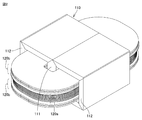
- FIG. 1 is a perspective view showing the appearance of the stationary guidance device according to the first embodiment of the present invention.
- FIG. 2 is a perspective view showing a part of the configuration of the stationary guidance device according to the first embodiment of the present invention.
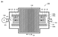
- FIG. 3 is a partial cross-sectional view of the rest guidance device shown in FIG. 1 as viewed from the direction of the arrow along line III-III.
- FIG. 4 is an exploded perspective view showing a laminated structure of a plurality of windings and a plurality of insulating plates included in the stationary induction device according to the first embodiment of the present invention.
- the rest induction device 100 is an in-vehicle transformer.
- the static induction device 100 according to the present embodiment is a so-called outer iron type transformer.
- the stationary induction device 100 includes an iron core 110, a plurality of windings 120, a plurality of insulating plates 130, and a tank 140.
- the plurality of insulating plates 130 are not shown.
- the iron core 110 includes a main landing gear portion 111 and a side landing gear portion 112.
- the side landing gear 112 is connected to the main landing gear 111.
- each of the plurality of windings 120 is wound around the iron core 110 with the iron core 110 as the central axis. Specifically, each of the plurality of windings 120 is wound around the main landing gear 111 while being passed between the main landing gear 111 and the side landing gear 112. In this way, each of the plurality of windings 120 is coaxially arranged. In the present embodiment, each of the plurality of windings 120 is a flat winding.
- each of the plurality of windings 120 includes a plurality of high-pressure windings 120a and a plurality of low-pressure windings 120b.
- the plurality of high-pressure windings 120a are located sandwiched between the pair of the plurality of low-pressure windings 120b.
- each of the plurality of insulating plates 130 is located so as to be sandwiched between the windings 120 adjacent to each other on a one-to-one basis in the plurality of windings 120.
- the configuration of each of the plurality of insulating plates 130 will be described later.
- the tank 140 houses an iron core 110, a plurality of windings 120, and a plurality of insulating plates 130.
- the tank 140 is filled with insulating oil.
- the tank 140 is configured such that insulating oil flows in the tank 140 in a first direction D1 orthogonal to the central axis direction of the plurality of windings 120.
- the stationary guidance device 100 further includes a circulation pipe 151.
- the circulation pipe 151 connects two connecting portions 141 located at both ends of the tank 140 in the first direction D1.
- a pump 154 is provided in the circulation pipe 151. When the pump 154 is operated, the insulating oil circulates in the tank 140 and the circulation pipe 151.
- a cooling container 153 is further connected to the circulation pipe 151.
- the cooling container 153 is cooled from the outside by the wind sent from the electric blower 152. As a result, the insulating oil that has flowed into the cooling container 153 is cooled and then flows into the circulation pipe 151 again.
- the insulating oil that has flowed in from one of the connecting portions 141 flows through the insulating oil flow path 10 formed between the plurality of windings 120 that are adjacent to each other. As a result, the heat of the winding 120 adjacent to the flow path 10 is transferred to the insulating oil. As a result, the plurality of windings 120 are cooled.
- the flow path 10 is composed of a plurality of insulating plates 130.
- the flow path 10 in the present embodiment will be described together with the configurations of the plurality of insulating plates 130.
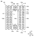
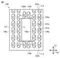
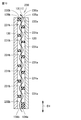
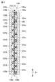
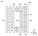
- FIG. 5 is a diagram showing the shape of the insulating plate according to the first embodiment of the present invention.
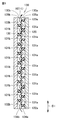
- FIG. 6 is a cross-sectional view of the insulating plate shown in FIG. 5 as viewed from the direction of the arrow along the VI-VI line.
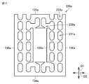
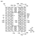
- FIG. 7 is a diagram showing the shape of the first plate-shaped portion of the insulating plate according to the first embodiment of the present invention.
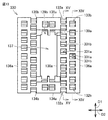
- FIG. 8 is a diagram showing the shape of the second plate-shaped portion of the insulating plate according to the first embodiment of the present invention.
- a plurality of windings 120 adjacent to the insulating plate 130 are shown together.
- each of the plurality of insulating plates 130 has a rectangular outer shape when viewed from the central axis direction of the plurality of windings 120.
- Each of the plurality of insulating plates 130 is located so that the longitudinal direction of each of the plurality of insulating plates 130 is along the first direction D1. That is, the lateral direction of each of the plurality of insulating plates 130 is located along the second direction D2 orthogonal to both the central axis direction and the first direction D1.
- Each of the plurality of insulating plates 130 is formed with an opening 137 penetrating in the central axis direction.
- the iron core 110 shown in FIG. 2 is located in the opening 137.
- the main landing gear 111 is located in the opening 137.
- each of the plurality of insulating plates 130 includes a first plate-shaped portion 130a and a second plate-shaped portion 130b that are adjacent to each other in the central axis direction.
- each of the plurality of insulating plates 130 is composed of a first plate-shaped portion 130a and a second plate-shaped portion 130b.
- Each of the first plate-shaped portion 130a and the second plate-shaped portion 130b is made of an insulating material, for example, an insulating paper such as a press board or an insulating material such as polyamide.
- first hole portions 131a penetrating in the central axis direction are formed in the first plate-shaped portion 130a.
- the first hole portion 131a has a rectangular outer shape, and specifically has a square outer shape.
- the first plate-shaped portion 130a is formed with a first notch portion 132a at one end edge 134a of the first direction D1. Specifically, a plurality of first notch portions 132a are formed in the first plate-shaped portion 130a. In the present embodiment, the angles formed by the corners of the plurality of first notches 132a of the first plate-shaped portion 130a are right angles.
- a second notch portion 133a is formed at the other end edge 135a in the first direction D1. Specifically, a plurality of second notch portions 133a are formed in the first plate-shaped portion 130a. In the present embodiment, the angles formed by the respective corners of the plurality of second notches 133a of the first plate-shaped portion 130a are right angles.
- the lateral edge 136a located on both sides of the first plate-shaped portion 130a in the second direction D2 has a linear outer shape along the first direction D1.
- a plurality of inner peripheral notches 139a are formed on the inner peripheral edge 138a of the first plate-shaped portion 130a.
- the plurality of inner peripheral notch portions 139a are located so as to be sandwiched between the plurality of first hole portions 131a in the first direction D1.
- each of the first hole portion 131a, the first plate-shaped portion 130a, the first notch portion 132a, and the second notch portion 133a when viewed from the central axis direction is not particularly limited.
- the outer shape of each of the first hole 131a, the first plate-shaped 130a, the first notch 132a, and the second notch 133a when viewed from the central axis direction is caused by the shape of the insulating oil flow path 10. It can be changed as appropriate to reduce the pressure loss.
- a plurality of second hole portions 131b penetrating in the central axis direction are formed in the second plate-shaped portion 130b.
- the second hole portion 131b has a rectangular outer shape, and specifically has a square outer shape.
- the second plate-shaped portion 130b is formed with a first notch portion 132b at one end edge 134b of the first direction D1. Specifically, a plurality of first notch portions 132b are formed in the second plate-shaped portion 130b. In the present embodiment, the angles formed by the corners of the plurality of first notches 132b of the second plate-shaped portion 130b are right angles.
- a second notch portion 133b is formed at the other end edge 135b in the first direction D1. Specifically, a plurality of second notch portions 133b are formed in the second plate-shaped portion 130b. In the present embodiment, the angles formed by the corners of the plurality of second notches 133b of the second plate-shaped portion 130b are right angles.
- the lateral edge 136b located on both sides of the second plate-shaped portion 130b in the second direction D2 has a linear outer shape along the first direction D1.
- a plurality of inner peripheral notches 139b are formed on the inner peripheral edge 138b of the second plate-shaped portion 130b.
- each of the second hole portion 131b, the first notch portion 132b of the second plate-shaped portion 130b, and the second notch portion 133b when viewed from the central axis direction is not particularly limited.
- the outer shape of each of the second hole portion 131b, the first notch portion 132b, and the second notch portion 133b of the second plate-shaped portion 130b when viewed from the central axis direction is caused by the shape of the insulating oil flow path 10. It can be changed as appropriate to reduce the pressure loss.
- At least one of the first plate-shaped portion 130a or the second plate-shaped portion 130b is formed with the first cutout portions 132a, 132b at one end edge 134a, 134b of the first direction D1.
- Second notches 133a, 133b are formed at the other edge 135a, 135b in the first direction D1.
- a flow path 10 through which insulating oil can flow is configured by communicating one side and the other side of each of the plurality of insulating plates 130 with each other.
- the flow path 10 when viewed from the central axis direction, includes a linear flow path 11 formed along the first direction D1.
- the flow path 10 includes a plurality of linear flow paths 11 when viewed from the central axis direction.
- the first hole portion 131a located on the onemost end edge 134a side overlaps with the first notch portion 132b.
- Each of the plurality of second hole portions 131b overlaps with both of the two first hole portions 131a adjacent to each other in the first direction D1.
- the first hole 131a located on the most 135a side overlaps the second notch 133b. In this way, the linear flow path 11 is configured.
- each of the plurality of inner peripheral notch portions 139a is two first hole portions of the plurality of first hole portions 131a arranged along the first direction D1. It may be located between 131a.
- the plurality of first hole portions 131a, the plurality of second hole portions 131b, the first notch portions 132a, 132b, the second notch portions 133a, 133b, and the plurality of 139a overlap each other.
- the flow path 10 is configured in the first direction D1.
- the plurality of first hole portions 131a, the plurality of second hole portions 131b, the first notch portions 132a, 132b and the second notch portion 133a , 133b are overlapped with each other, so that in the first direction D1, one side and the other side of each of the plurality of insulating plates 130 are communicated with each other to form a flow path 10 through which insulating oil can flow. There is.
- the flow path 10 includes a linear flow path 11 formed along the first direction D1 when viewed from the central axis direction.
- the insulating oil flowing through the linear flow path 11 has the winding 120 adjacent to the first plate-shaped portion 130a and the winding 120 adjacent to the second plate-shaped portion 130b. It can be cooled alternately. As a result, the plurality of windings 120 can be efficiently cooled as a whole.
- Embodiment 2 the rest guidance device according to the second embodiment of the present invention will be described.
- the static guidance device according to the second embodiment of the present invention differs from the static guidance device 100 according to the first embodiment of the present invention only in the configuration of each of the plurality of insulating plates. Therefore, the description of the configuration similar to that of the rest guidance device 100 according to the first embodiment of the present invention will not be repeated.
- FIG. 9 is a diagram showing the shape of the insulating plate according to the second embodiment of the present invention.
- FIG. 10 is a cross-sectional view of the insulating plate shown in FIG. 9 as viewed from the direction of the XX line arrow.
- FIG. 11 is a diagram showing the shape of the first plate-shaped portion of the insulating plate according to the second embodiment of the present invention.
- FIG. 12 is a diagram showing the shape of the second plate-shaped portion of the insulating plate according to the second embodiment of the present invention.
- the plurality of insulating plates 230 according to the second embodiment of the present invention have the plurality of first hole portions 231a of the first plate-shaped portion 230a when viewed from the central axis direction. Further, each corner of the second hole portion 231b of the second plate-shaped portion 230b is rounded. As a result, the pressure loss in the flow path 10 when the insulating oil flows through the flow path 10 can be reduced.
- the plurality of first notch portions 232b, the plurality of second notch portions 233a and 233b, and the plurality of inner peripheral notch portions 239a and 239b are also rounded. Includes tinged corners.
- the rest guidance device according to the third embodiment of the present invention is mainly the position of each of the plurality of first holes and the plurality of second holes with the rest guidance device 100 according to the first embodiment of the present invention. different. Therefore, the description of the configuration similar to that of the rest guidance device 100 according to the first embodiment of the present invention will not be repeated.
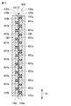
- FIG. 13 is a diagram showing the shape of the insulating plate according to the third embodiment of the present invention.
- FIG. 14 is a view of the insulating plate shown in FIG. 13 as viewed from the direction of the XIV-XIV line arrow.
- FIG. 15 is a view of the insulating plate shown in FIG. 13 as viewed from the direction of the XV-XV line arrow.
- FIG. 16 is a diagram showing the shape of the first plate-shaped portion of the insulating plate according to the third embodiment of the present invention.
- FIG. 17 is a diagram showing the shape of the second plate-shaped portion of the insulating plate according to the third embodiment of the present invention.
- each of the plurality of first hole portions 331a of the first plate-shaped portion 330a is a plurality of straight lines adjacent to each other. It constitutes a part of one of the linear flow paths 11X. As shown in FIGS. 13 and 15, each of the plurality of first hole portions 331a constitutes a part of the other linear flow path 11Y among the plurality of linear flow paths adjacent to each other. As shown in FIGS. 13 and 16, the plurality of first hole portions 331a constituting one linear flow path 11X and the plurality of first hole portions 331a constituting the other linear flow path 11Y are first. They are staggered in direction D1.
- each of the plurality of second hole portions 331b of the second plate-shaped portion 330b is one of the linear flow paths 11X of the plurality of linear flow paths 11 adjacent to each other. It constitutes a part. As shown in FIGS. 13 and 15, each of the plurality of second hole portions 331b constitutes a part of the other linear flow path 11Y among the plurality of linear flow paths adjacent to each other. As shown in FIGS. 13 and 17, the plurality of second hole portions 331b constituting one linear flow path 11X and the plurality of second hole portions 331b constituting the other linear flow path 11Y are the first. They are staggered in direction D1 of 1.
- the portion of the plurality of windings 120 that is not adjacent to one linear flow path 11X is the other. It is adjacent to the linear flow path 11Y. Further, when viewed from the second direction D2, the portion of the plurality of windings 120 that is not adjacent to the other linear flow path 11Y is adjacent to one linear flow path 11X. Thereby, each of the plurality of insulating plates 330 and each of the plurality of windings 120 adjacent to each other can be uniformly cooled.
- the rest guidance device according to the fourth embodiment of the present invention is mainly the position of each of the plurality of first holes and the plurality of second holes with the rest guidance device 100 according to the first embodiment of the present invention. different. Therefore, the description of the configuration similar to that of the rest guidance device 100 according to the first embodiment of the present invention will not be repeated.
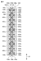
- FIG. 18 is a diagram showing the shape of the insulating plate according to the fourth embodiment of the present invention.
- FIG. 19 is a view of the insulating plate shown in FIG. 18 as viewed from the direction of the XIX-XIX line arrow.
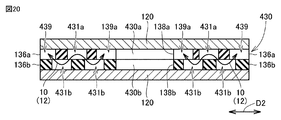
- FIG. 20 is a view of the insulating plate shown in FIG. 18 as viewed from the direction of the XX-XX line arrow.
- FIG. 21 is a diagram showing the shape of the first plate-shaped portion of the insulating plate according to the fourth embodiment of the present invention.
- FIG. 22 is a diagram showing the shape of the second plate-shaped portion of the insulating plate according to the fourth embodiment of the present invention.
- the first plate-shaped portion 430a and the second plate-shaped portion 430b cause one side of each of the plurality of insulating plates 430 in the first direction D1.
- a plurality of flow paths 10 are configured so that the insulating oil can flow through the other side and the other side.
- insulating oil can flow from the side edge edges 136a and 136b to the inner peripheral edge edges 138a and 138b in the second direction D2.
- the flow path 10 is configured. As shown in FIG. 20, the flow path 10 along the second direction D2 is formed in, for example, a plurality of first hole portions 431a, a plurality of second hole portions 431b, an inner peripheral notch portion 139a, and a lateral end edge 136a.
- the side cutouts 439 are overlapped with each other.
- Each of the flow paths 10 of the above is connected to each other.
- the flow path 10 includes the reticulated flow path 12 when viewed from the central axis direction.
- each of the plurality of first hole portions 431a and the plurality of second hole portions 431b is viewed from the central axis direction.
- the central portion of each of the plurality of first hole portions 431a and the central portion of each of the plurality of second hole portions 431b are located in a zigzag shape with respect to each other.
- the flow path 10 includes a braided flow path 12. Since the insulating oil can flow while taking various paths in the net-like flow path 12, the plurality of windings 120 in contact with each of the plurality of insulating plates 430 can be cooled more uniformly.
- Embodiment 5 the rest guidance device according to the fifth embodiment of the present invention will be described.
- the static induction device according to the fifth embodiment of the present invention is mainly different from the static induction device according to the fourth embodiment of the present invention in the number of plate-shaped portions constituting the insulating plate. Therefore, the description of the configuration similar to that of the stationary guidance device according to the fourth embodiment of the present invention will not be repeated.
- FIG. 23 is a cross-sectional view showing the configuration of the insulating plate according to the fifth embodiment of the present invention. In addition, in FIG. 23, it is shown in the same cross-sectional view as FIG. 19 showing the insulating plate 430 of the fourth embodiment of the present invention.
- the plurality of insulating plates 530 and the second plate-shaped portion 430b on the side opposite to the first plate-shaped portion 430a side in the central axis direction.
- An adjacent third plate-shaped portion 530c is further provided.
- the plurality of insulating plates 530 are composed of a first plate-shaped portion 430a, a second plate-shaped portion 430b, and a third plate-shaped portion 530c.
- the third plate-shaped portion 530c has the same shape as the first plate-shaped portion 430a, and is located so as to be symmetrical with respect to the first plate-shaped portion 430a with respect to the second plate-shaped portion 430b.
Landscapes
- Engineering & Computer Science (AREA)
- Power Engineering (AREA)
- Chemical & Material Sciences (AREA)
- Combustion & Propulsion (AREA)
- Coils Of Transformers For General Uses (AREA)
- Insulating Of Coils (AREA)
- Transformer Cooling (AREA)
Abstract
第1板状部(130a)には、中心軸方向に貫通する複数の第1孔部(131a)が形成されている。第2板状部(130b)には、中心軸方向に貫通する複数の第2孔部(131b)が形成されている。複数の第1孔部(131a)、複数の第2孔部(131b)、第1切欠部(132a,132b)および第2切欠部(133a,133b)が互いに重なり合っていることにより、第1の方向(D1)において、複数の絶縁板(130)の各々の一方側と他方側とを互いに連通して絶縁油が通流可能な流路(10)が構成されている。
Description
本発明は、静止誘導機器に関する。
静止誘導機器の構成を開示した文献として、実開昭58-196814号公報(特許文献1)がある。特許文献1に記載された静止誘導機器である変圧器において、高圧巻線と低圧巻線との間は、平板状の巻線間絶縁板によって絶縁されている。高圧巻線と低圧巻線との間には、平板状絶縁板の表面に絶縁片を貼り付けることにより、油ダクトが構成される。タンク内には、これらの部材が配設されており、絶縁油が満たされている。絶縁油は、巻線の一方の端部より高圧巻線と低圧巻線の間に入り、これらの巻線間の通過する間に巻線の熱を受け取って加熱される。絶縁油は、巻線の他方の端部より外部に送り出され、配管を通って油ポンプにより油冷却器に送り込まれた後、送風器にて冷却されてタンクに戻る。
従来の静止誘導機器が備える複数の巻線間において、絶縁油は、絶縁板に貼り付けられた複数の絶縁片の間を流れる場合がある。この場合、複数の絶縁片は、形成される流路を考慮して1つずつ配置される。このため、複数の絶縁片を貼り付ける作業は繁雑となる。
本発明は上記問題点に鑑みてなされたものであり、複数の巻線間において絶縁油の流路を容易に形成できる、静止誘導機器を提供することを目的とする。
本発明に基づく静止誘導機器は、鉄心と、複数の巻線と、複数の絶縁板と、タンクとを備えている。複数の巻線の各々は、鉄心を中心軸として鉄心に巻き回されている。複数の巻線の各々は、同軸配置されている。複数の絶縁板の各々は、複数の巻線において互いに隣り合う巻線同士の間に1対1で対応して挟まれて位置している。タンクは、鉄心、複数の巻線および複数の絶縁板を収容している。タンクは、内部に絶縁油が充填されている。タンクは、タンク内において複数の巻線の中心軸方向と直交する第1の方向に絶縁油が流れるように構成されている。複数の絶縁板の各々は、中心軸方向において互いに隣接する第1板状部および第2板状部を含んでいる。第1板状部には、中心軸方向に貫通する複数の第1孔部が形成されている。第2板状部には、中心軸方向に貫通する複数の第2孔部が形成されている。第1板状部または第2板状部の少なくとも一方には、第1の方向の一方の端縁において第1切欠部が形成され、かつ、第1の方向の他方の端縁において第2切欠部が形成されている。複数の第1孔部、複数の第2孔部、第1切欠部および第2切欠部が互いに重なり合っていることにより、第1の方向において、複数の絶縁板の各々の一方側と他方側とを互いに連通して絶縁油が通流可能な流路が構成されている。
本発明によれば、絶縁板上に複数の絶縁片を配置することなく、第1板状部と第2板状部とを互いに隣接させることで、複数の巻線間において絶縁油の流路を容易に形成できる。
以下、本発明の各実施の形態に係る静止誘導機器について図面を参照して説明する。以下の実施の形態の説明においては、図中の同一または相当部分には同一符号を付して、その説明は繰り返さない。
実施の形態1.
図1は、本発明の実施の形態1に係る静止誘導機器の外観を示す斜視図である。図2は、本発明の実施の形態1に係る静止誘導機器の構成の一部を示す斜視図である。図3は、図1に示した静止誘導機器をIII-III線矢印方向から見た一部断面図である。図4は、本発明の実施の形態1に係る静止誘導機器が備える複数の巻線および複数の絶縁板の積層構造を示す分解斜視図である。
図1は、本発明の実施の形態1に係る静止誘導機器の外観を示す斜視図である。図2は、本発明の実施の形態1に係る静止誘導機器の構成の一部を示す斜視図である。図3は、図1に示した静止誘導機器をIII-III線矢印方向から見た一部断面図である。図4は、本発明の実施の形態1に係る静止誘導機器が備える複数の巻線および複数の絶縁板の積層構造を示す分解斜視図である。
図1から図4に示すように、本発明の実施の形態1に係る静止誘導機器100は、車載用変圧器である。また、本実施の形態に係る静止誘導機器100は、いわゆる外鉄形変圧器である。
図1から図4に示すように、静止誘導機器100は、鉄心110と、複数の巻線120と、複数の絶縁板130と、タンク140とを備えている。図2および図3において、複数の絶縁板130は図示していない。
図2に示すように、鉄心110は、主脚部111と、側脚部112とを含んでいる。側脚部112は、主脚部111に接続されている。
図1および図2に示すように、複数の巻線120の各々は、鉄心110を中心軸として鉄心110に巻き回されている。具体的には、複数の巻線120の各々は、主脚部111と側脚部112との間に通されつつ、主脚部111に巻き回される。このように、複数の巻線120の各々は、同軸配置されている。本実施の形態において、複数の巻線120の各々は平板状巻線である。
図1から図3に示すように、複数の巻線120の各々は、複数の高圧巻線120aと、複数の低圧巻線120bとを含んでいる。複数の巻線120の中心軸方向において、複数の高圧巻線120aは、一対の複数の低圧巻線120bに挟まれて位置している。
図4に示すように、複数の絶縁板130の各々は、複数の巻線120において互いに隣り合う巻線120同士の間に1対1で対応して挟まれて位置している。複数の絶縁板130の各々の構成については後述する。
図3および図4に示すように、タンク140は、鉄心110、複数の巻線120および複数の絶縁板130を収容している。タンク140には、内部に絶縁油が充填されている。タンク140は、タンク140内において複数の巻線120の中心軸方向と直交する第1の方向D1に絶縁油が流れるように構成されている。
図1および図3に示すように、静止誘導機器100は、循環配管151をさらに備えている。循環配管151は、タンク140の第1の方向D1における両端部の各々に位置する2つの接続部141同士を接続している。循環配管151には、ポンプ154が設けられている。このポンプ154が稼働することにより、絶縁油が、タンク140内および循環配管151内を循環する。
循環配管151には、さらに冷却容器153が接続されている。冷却容器153は、電動送風機152から送られた風によって、外側から冷却される。これにより、冷却容器153内に流入した絶縁油は、冷却されたのち、再び循環配管151内に流入する。
一方の接続部141から流入した絶縁油は、互いに隣接する複数の巻線120同士の間に形成された絶縁油の流路10を流れる。これにより、流路10に隣接する巻線120の熱が絶縁油に移動する。結果として、複数の巻線120が冷却される。
流路10は、複数の絶縁板130によって構成されている。以下、本実施の形態における流路10を、複数の絶縁板130の構成とともに説明する。
図5は、本発明の実施の形態1における絶縁板の形状を示す図である。図6は、図5に示した絶縁板をVI-VI線矢印方向から見た断面図である。図7は、本発明の実施の形態1における絶縁板の第1板状部の形状を示す図である。図8は、本発明の実施の形態1における絶縁板の第2板状部の形状を示す図である。なお、図6においては、絶縁板130に隣接する複数の巻線120を共に図示している。
図4および図5に示すように、複数の絶縁板130の各々は、複数の巻線120の中心軸方向から見たときに、矩形状の外形を有している。複数の絶縁板130の各々は、複数の絶縁板130の各々の長手方向が第1の方向D1に沿うように位置している。すなわち、複数の絶縁板130の各々の短手方向は、上記中心軸方向および第1の方向D1の両方に直交する第2の方向D2に沿うように位置している。
複数の絶縁板130の各々には、上記中心軸方向に貫通する開口部137が形成されている。開口部137には、図2に示した鉄心110が位置している。具体的には、開口部137には、主脚部111が位置している。
図4から図6に示すように、複数の絶縁板130の各々は、中心軸方向において互いに隣接する第1板状部130aおよび第2板状部130bを含んでいる。本実施の形態において、複数の絶縁板130の各々は、第1板状部130aと第2板状部130bとから構成されている。第1板状部130aおよび第2板状部130bの各々は、絶縁性材料で構成され、たとえば、プレスボードなどの絶縁紙またはポリアミドなどの絶縁性材料などで構成されている。
図7に示すように、第1板状部130aには、中心軸方向に貫通する複数の第1孔部131aが形成されている。中心軸方向から見たときに、第1孔部131aは矩形状の外形を有しており、具体的には正方形状の外形を有している。
本実施の形態において、第1板状部130aには、第1の方向D1の一方の端縁134aにおいて、第1切欠部132aが形成されている。具体的には、第1板状部130aには、複数の第1切欠部132aが形成されている。本実施の形態において、第1板状部130aの複数の第1切欠部132a各々の角部のなす角は直角である。
第1板状部130aには、第1の方向D1の他方の端縁135aにおいて、第2切欠部133aが形成されている。具体的には、第1板状部130aには、複数の第2切欠部133aが形成されている。本実施の形態において、第1板状部130aの複数の第2切欠部133aの各々の角部のなす角は直角である。
第1板状部130aの第2の方向D2の両側に位置する側方端縁136aは、第1の方向D1に沿う直線状の外形を有している。
第1板状部130aの内周端縁138aには、複数の内周切欠部139aが形成されている。複数の内周切欠部139aは、第1の方向D1において、複数の第1孔部131aの間に挟まれるように位置している。
中心軸方向から見たときの第1孔部131a、第1板状部130aの第1切欠部132aおよび第2切欠部133aの各々の外形の形状は、特に限定されない。中心軸方向から見たときの第1孔部131a、第1板状部130aの第1切欠部132aおよび第2切欠部133aの各々の外形の形状は、絶縁油の流路10の形状によって生じる圧力損失を低減するために、適宜変更可能である。
図8に示すように、第2板状部130bには、中心軸方向に貫通する複数の第2孔部131bが形成されている。中心軸方向から見たときに、第2孔部131bは矩形状の外形を有しており、具体的には正方形状の外形を有している。
本実施の形態において、第2板状部130bには、第1の方向D1の一方の端縁134bにおいて、第1切欠部132bが形成されている。具体的には、第2板状部130bには、複数の第1切欠部132bが形成されている。本実施の形態において、第2板状部130bの複数の第1切欠部132bの各々の角部のなす角は直角である。
第2板状部130bには、第1の方向D1の他方の端縁135bにおいて、第2切欠部133bが形成されている。具体的には、第2板状部130bには、複数の第2切欠部133bが形成されている。本実施の形態において、第2板状部130bの複数の第2切欠部133bの角部のなす角は直角である。
第2板状部130bの第2の方向D2の両側に位置する側方端縁136bは、第1の方向D1に沿う直線状の外形を有している。第2板状部130bの内周端縁138bには、複数の内周切欠部139bが形成されている。
中心軸方向から見たときの第2孔部131b、第2板状部130bの第1切欠部132bおよび第2切欠部133bの各々の外形の形状は、特に限定されない。中心軸方向から見たときの第2孔部131b、第2板状部130bの第1切欠部132bおよび第2切欠部133bの各々の外形の形状は、絶縁油の流路10の形状によって生じる圧力損失を低減するために、適宜変更可能である。
上記のように、第1板状部130aまたは第2板状部130bの少なくとも一方には、第1の方向D1の一方の端縁134a,134bにおいて第1切欠部132a,132bが形成され、かつ、第1の方向D1の他方の端縁135a,135bにおいて第2切欠部133a,133bが形成されている。
そして、図5および図6に示すように、複数の第1孔部131a、複数の第2孔部131b、第1切欠部132a,132bおよび第2切欠部133a,133bが互いに重なり合っていることにより、第1の方向D1において、複数の絶縁板130の各々の一方側と他方側とを互いに連通して絶縁油が通流可能な流路10が構成されている。
図5および図6に示すように、上記中心軸方向から見たときに、流路10は、第1の方向D1に沿うように形成された直線状流路11を含んでいる。本実施の形態においては、中心軸方向から見たときに、流路10が、複数の直線状流路11を含んでいる。
本実施の形態においては、たとえば図6に示すように、最も一方の端縁134a側に位置する第1孔部131aが、第1切欠部132bと重なっている。複数の第2孔部131bの各々は、第1の方向D1において互いに隣り合う2つの第1孔部131aの両方と重なっている。最も135a側に位置する第1孔部131aが、第2切欠部133bと重なっている。このようにして、直線状流路11が構成されている。
また、図5および図7に示すように、複数の内周切欠部139aの各々が、第1の方向D1に沿って並んでいる複数の第1孔部131aのうちの2つの第1孔部131aの間に位置していてもよい。この場合、直線状流路11は、複数の第1孔部131a、複数の第2孔部131b、第1切欠部132a,132b、第2切欠部133a,133bおよび、複数の139aが互いに重なりあっていることにより、第1の方向D1において、流路10が構成される。
上記のように、本発明の実施の形態1に係る静止誘導機器100においては、複数の第1孔部131a、複数の第2孔部131b、第1切欠部132a,132bおよび第2切欠部133a,133bが互いに重なり合っていることにより、第1の方向D1において、複数の絶縁板130の各々の一方側と他方側とを互いに連通して絶縁油が通流可能な流路10が構成されている。これにより、複数の絶縁板130の各々の面上に複数の絶縁片を配置することなく、第1板状部130aと第2板状部130bとを互いに隣接させることで、互いに隣り合う複数の巻線120同士の間において絶縁油の流路10を容易に形成できる。
本発明の実施の形態1においては、中心軸方向から見たときに、流路10は、第1の方向D1に沿うように形成された直線状流路11を含んでいる。これにより、第1の方向D1において、直線状流路11を流れる絶縁油は、第1板状部130aと隣接する巻線120と、第2板状部130bと隣接する巻線120とを、交互に冷却することができる。ひいては、複数の巻線120を全体的に効率よく冷却することができる。
実施の形態2.
以下、本発明の実施の形態2に係る静止誘導機器について説明する。本発明の実施の形態2に係る静止誘導機器は、本発明の実施の形態1に係る静止誘導機器100とは、複数の絶縁板の各々の構成のみが異なる。このため、本発明の実施の形態1に係る静止誘導機器100と同様である構成については説明を繰り返さない。
以下、本発明の実施の形態2に係る静止誘導機器について説明する。本発明の実施の形態2に係る静止誘導機器は、本発明の実施の形態1に係る静止誘導機器100とは、複数の絶縁板の各々の構成のみが異なる。このため、本発明の実施の形態1に係る静止誘導機器100と同様である構成については説明を繰り返さない。
図9は、本発明の実施の形態2における絶縁板の形状を示す図である。図10は、図9に示した絶縁板をX-X線矢印方向から見た断面図である。図11は、本発明の実施の形態2における絶縁板の第1板状部の形状を示す図である。図12は、本発明の実施の形態2における絶縁板の第2板状部の形状を示す図である。
図9から図12に示すように、本発明の実施の形態2における複数の絶縁板230は、上記中心軸方向から見たときに、第1板状部230aの複数の第1孔部231a、および、第2板状部230bの第2孔部231bの各々の角部が丸みを帯びている。これにより、絶縁油が流路10を通流するときの、流路10内の圧力損失を低減することができる。
本実施の形態においては、上記中心軸方向から見たときに、複数の第1切欠部232b、複数の第2切欠部233a,233b、複数の内周切欠部239a,239bの各々も、丸みを帯びた角部を含んでいる。
実施の形態3.
以下、本発明の実施の形態3に係る静止誘導機器について説明する。本発明の実施の形態3に係る静止誘導機器は、本発明の実施の形態1に係る静止誘導機器100とは、複数の第1孔部および複数の第2孔部の各々の位置が主に異なる。このため、本発明の実施の形態1に係る静止誘導機器100と同様である構成については説明を繰り返さない。
以下、本発明の実施の形態3に係る静止誘導機器について説明する。本発明の実施の形態3に係る静止誘導機器は、本発明の実施の形態1に係る静止誘導機器100とは、複数の第1孔部および複数の第2孔部の各々の位置が主に異なる。このため、本発明の実施の形態1に係る静止誘導機器100と同様である構成については説明を繰り返さない。
図13は、本発明の実施の形態3における絶縁板の形状を示す図である。図14は、図13に示した絶縁板をXIV-XIV線矢印方向から見た図である。図15は、図13に示した絶縁板をXV-XV線矢印方向から見た図である。図16は、本発明の実施の形態3における絶縁板の第1板状部の形状を示す図である。図17は、本発明の実施の形態3における絶縁板の第2板状部の形状を示す図である。
本発明の実施の形態3の複数の絶縁板330においては、図13および図14に示すように、第1板状部330aの複数の第1孔部331aの各々が、互いに隣り合う複数の直線状流路のうちの一方の直線状流路11Xの一部を構成している。図13および図15に示すように、複数の第1孔部331aの各々は、互いに隣り合う複数の直線状流路のうちの他方の直線状流路11Yの一部を構成している。一方の直線状流路11Xを構成する複数の第1孔部331aと、他方の直線状流路11Yを構成する複数の第1孔部331aとは、図13および16に示すように、第1の方向D1において互い違いに位置している。図13および図14に示すように、第2板状部330bの複数の第2孔部331bの各々が、互いに隣り合う複数の直線状流路11のうちの一方の直線状流路11Xの一部を構成している。図13および図15に示すように、複数の第2孔部331bの各々は、互いに隣り合う複数の直線状流路のうちの他方の直線状流路11Yの一部を構成している。一方の直線状流路11Xを構成する複数の第2孔部331bと、他方の直線状流路11Yを構成する複数の第2孔部331bとは、図13および図17に示すように、第1の方向D1において互い違いに位置している。
上記の構成により、図14および図15に示すように、第2の方向D2から見たときに、複数の巻線120において、一方の直線状流路11Xと隣接していない部分は、他方の直線状流路11Yと隣接している。また、第2の方向D2から見たときに、複数の巻線120において、他方の直線状流路11Yと隣接していない部分は、一方の直線状流路11Xと隣接している。これにより、複数の絶縁板330の各々と互いに隣接する複数の巻線120の各々を均一に冷却することができる。
実施の形態4.
以下、本発明の実施の形態4に係る静止誘導機器について説明する。本発明の実施の形態4に係る静止誘導機器は、本発明の実施の形態1に係る静止誘導機器100とは、複数の第1孔部および複数の第2孔部の各々の位置が主に異なる。このため、本発明の実施の形態1に係る静止誘導機器100と同様である構成については説明を繰り返さない。
以下、本発明の実施の形態4に係る静止誘導機器について説明する。本発明の実施の形態4に係る静止誘導機器は、本発明の実施の形態1に係る静止誘導機器100とは、複数の第1孔部および複数の第2孔部の各々の位置が主に異なる。このため、本発明の実施の形態1に係る静止誘導機器100と同様である構成については説明を繰り返さない。
図18は、本発明の実施の形態4における絶縁板の形状を示す図である。図19は、図18に示した絶縁板をXIX-XIX線矢印方向から見た図である。図20は、図18に示した絶縁板をXX-XX線矢印方向から見た図である。図21は、本発明の実施の形態4における絶縁板の第1板状部の形状を示す図である。図22は、本発明の実施の形態4における絶縁板の第2板状部の形状を示す図である。
図18および図19に示すように、本実施の形態においても、第1板状部430aと第2板状部430bとによって、第1の方向D1において、複数の絶縁板430の各々の一方側と他方側とを互いに連通して絶縁油が通流可能な、複数の流路10が構成されている。
さらに、本実施の形態においては、図18および図20に示すように、第2の方向D2において、側方端縁136a,136bから内周端縁138a,138bまで、絶縁油が通流可能な流路10が構成されている。図20に示すように、第2の方向D2に沿う流路10は、たとえば、複数の第1孔部431a、複数の第2孔部431b、内周切欠部139a、側方端縁136aに形成された側方切欠部439が互いに重なり合っていることにより構成されている。
図18から図20に示すように、中心軸方向から見たときに第1の方向D1に沿う複数の流路10の各々と、中心軸方向から見たときに第2の方向D2に沿う複数の流路10の各々とは、互いに接続されている。このように、本発明の実施の形態4においては、中心軸方向から見たときに、流路10が、網状流路12を含んでいる。
本発明の実施の形態4においては、図18、図21および図22に示すように、複数の第1孔部431aおよび複数の第2孔部431bの各々は、中心軸方向から見たときに、複数の第1孔部431aの各々の中心部と、複数の第2孔部431bの各々の中心部とが、互いにジグザグ状に位置している。
本発明の実施の形態4に係る静止誘導機器においては、上記のように複数の第1孔部431aと複数の第2孔部431bとが配置されることにより、中心軸方向から見たときに、流路10が、網状流路12を含んでいる。絶縁油は、網状流路12中の様々な経路をとりつつ流れることができるため、複数の絶縁板430の各々と接触する複数の巻線120を、より均一に冷却することができる。
実施の形態5.
以下、本発明の実施の形態5に係る静止誘導機器について説明する。本発明の実施の形態5に係る静止誘導機器は、本発明の実施の形態4に係る静止誘導機器とは、絶縁板を構成する板状部の数が主に異なる。このため、本発明の実施の形態4に係る静止誘導機器と同様である構成については説明を繰り返さない。
以下、本発明の実施の形態5に係る静止誘導機器について説明する。本発明の実施の形態5に係る静止誘導機器は、本発明の実施の形態4に係る静止誘導機器とは、絶縁板を構成する板状部の数が主に異なる。このため、本発明の実施の形態4に係る静止誘導機器と同様である構成については説明を繰り返さない。
図23は、本発明の実施の形態5における絶縁板の構成を示す断面図である。なお、図23においては、本発明の実施の形態4の絶縁板430を示した図19と同一の断面視にて図示している。
図23に示すように、本発明の実施の形態5においては、複数の絶縁板530は、上記中心軸方向において、第1板状部430a側とは反対側において第2板状部430bと互いに隣接する第3板状部530cをさらに備えている。本実施の形態において、複数の絶縁板530は、第1板状部430a、第2板状部430bおよび第3板状部530cで構成されている。
第3板状部530cは、第1板状部430aと同一の形状を有しており、第2板状部430bに関して第1板状部430aと対称となるように位置している。これにより、複数の絶縁板530の各々と隣接する2つの巻線120の各々において、巻線120と接触する2つの流路10の構成が、互いに同一となる。これにより、複数の巻線120の各々を、同じように冷却することができる。
上述した実施の形態の説明において、組み合わせ可能な構成を相互に組み合わせてもよい。
なお、今回開示した上記実施の形態はすべての点で例示であって、限定的な解釈の根拠となるものではない。したがって、本発明の技術的範囲は、上記した実施の形態のみによって解釈されるものではなく、請求の範囲の記載に基づいて画定される。また、請求の範囲と均等の意味および範囲内でのすべての変更が含まれる。
10 流路、11,11X,11Y 直線状流路、12 網状流路、100 静止誘導機器、110 鉄心、111 主脚部、112 側脚部、120 巻線、120a 高圧巻線、120b 低圧巻線、130,230,330,430,530 絶縁板、130a,230a,330a,430a 第1板状部、130b,230b,330b,430b 第2板状部、131a,231a,331a,431a 第1孔部、131b,231b,331b,431b 第2孔部、132a,132b,232b 第1切欠部、133a,133b,233a,233b 第2切欠部、134a,134b 一方の端縁、135a,135b 他方の端縁、136a,136b 側方端縁、137 開口部、138a,138b 内周端縁、139a,139b,239a,239b 内周切欠部、140 タンク、141 接続部、151 循環配管、152 電動送風機、153 冷却容器、154 ポンプ、439 側方切欠部、530c 第3板状部、D1 第1の方向、D2 第2の方向。
Claims (5)
- 鉄心と、
前記鉄心を中心軸として前記鉄心に巻き回されて、同軸配置されている複数の巻線と、
前記複数の巻線において互いに隣り合う巻線同士の間に1対1で対応して挟まれて位置している複数の絶縁板と、
前記鉄心、前記複数の巻線および前記複数の絶縁板を収容し、内部に絶縁油が充填されたタンクとを備え、
前記タンクは、前記タンク内において前記複数の巻線の中心軸方向と直交する第1の方向に前記絶縁油が流れるように構成されており、
前記複数の絶縁板の各々は、前記中心軸方向において互いに隣接する第1板状部および第2板状部を含み、
前記第1板状部には、前記中心軸方向に貫通する複数の第1孔部が形成されており、
前記第2板状部には、前記中心軸方向に貫通する複数の第2孔部が形成されており、
前記第1板状部または前記第2板状部の少なくとも一方には、前記第1の方向の一方の端縁において第1切欠部が形成され、かつ、前記第1の方向の他方の端縁において第2切欠部が形成されており、
前記複数の第1孔部、前記複数の第2孔部、前記第1切欠部および前記第2切欠部が互いに重なり合っていることにより、前記第1の方向において、前記複数の絶縁板の各々の一方側と他方側とを互いに連通して前記絶縁油が通流可能な流路が構成されている、静止誘導機器。 - 前記中心軸方向から見たときに、前記流路は、前記第1の方向に沿うように形成された直線状流路を含んでいる、請求項1に記載の静止誘導機器。
- 前記中心軸方向から見たときに、前記流路が、複数の前記直線状流路を含み、
互いに隣り合う複数の前記直線状流路のうちの一方の前記直線状流路を構成する前記複数の第1孔部と、他方の前記直線状流路を構成する前記複数の第1孔部とが、前記第1の方向において互い違いに位置しており、
互いに隣り合う複数の前記直線状流路のうちの一方の前記直線状流路を構成する前記複数の第2孔部と、他方の前記直線状流路を構成する前記複数の第2孔部とが、前記第1の方向において互い違いに位置している、請求項2に記載の静止誘導機器。 - 前記中心軸方向から見たときに、前記流路が、網状流路を含み、
前記複数の第1孔部および前記複数の第2孔部の各々は、前記中心軸方向から見たときに、前記複数の第1孔部の各々の中心部と、前記複数の第2孔部の各々の中心部とが、互いにジグザグ状に位置している、請求項1に記載の静止誘導機器。 - 前記複数の絶縁板は、前記中心軸方向において、第1板状部側とは反対側において前記第2板状部と互いに隣接する第3板状部をさらに備え、
前記第3板状部は、前記第1板状部と同一の形状を有しており、前記第2板状部に関して前記第1板状部と対称となるように位置している、請求項1から請求項4のいずれか1項に記載の静止誘導機器。
Priority Applications (4)
| Application Number | Priority Date | Filing Date | Title |
|---|---|---|---|
| US17/429,081 US12009134B2 (en) | 2019-04-25 | 2019-04-25 | Stationary induction apparatus |
| PCT/JP2019/017608 WO2020217376A1 (ja) | 2019-04-25 | 2019-04-25 | 静止誘導機器 |
| JP2019547737A JP6612009B1 (ja) | 2019-04-25 | 2019-04-25 | 静止誘導機器 |
| EP19926516.6A EP3961663B1 (en) | 2019-04-25 | 2019-04-25 | Stationary induction apparatus |
Applications Claiming Priority (1)
| Application Number | Priority Date | Filing Date | Title |
|---|---|---|---|
| PCT/JP2019/017608 WO2020217376A1 (ja) | 2019-04-25 | 2019-04-25 | 静止誘導機器 |
Publications (1)
| Publication Number | Publication Date |
|---|---|
| WO2020217376A1 true WO2020217376A1 (ja) | 2020-10-29 |
Family
ID=68692061
Family Applications (1)
| Application Number | Title | Priority Date | Filing Date |
|---|---|---|---|
| PCT/JP2019/017608 Ceased WO2020217376A1 (ja) | 2019-04-25 | 2019-04-25 | 静止誘導機器 |
Country Status (4)
| Country | Link |
|---|---|
| US (1) | US12009134B2 (ja) |
| EP (1) | EP3961663B1 (ja) |
| JP (1) | JP6612009B1 (ja) |
| WO (1) | WO2020217376A1 (ja) |
Families Citing this family (1)
| Publication number | Priority date | Publication date | Assignee | Title |
|---|---|---|---|---|
| WO2021201851A1 (en) * | 2020-03-31 | 2021-10-07 | General Electric Company | Liquid/fluid cooling systems for high power-density (hpd) transformers |
Citations (4)
| Publication number | Priority date | Publication date | Assignee | Title |
|---|---|---|---|---|
| JPS4883365A (ja) * | 1972-02-05 | 1973-11-07 | ||
| JPS5426623U (ja) * | 1977-07-26 | 1979-02-21 | ||
| JPS58196814U (ja) | 1982-06-24 | 1983-12-27 | 株式会社東芝 | 外鉄形油入変圧器 |
| WO2016009521A1 (ja) * | 2014-07-17 | 2016-01-21 | 三菱電機株式会社 | 車載用変圧装置 |
Family Cites Families (3)
| Publication number | Priority date | Publication date | Assignee | Title |
|---|---|---|---|---|
| JPS5033616Y1 (ja) | 1969-12-17 | 1975-10-01 | ||
| EP2040273B1 (en) * | 2006-07-10 | 2016-07-20 | Mitsubishi Electric Corporation | Transformer for vehicles |
| JP5349609B2 (ja) | 2009-10-21 | 2013-11-20 | 三菱電機株式会社 | 静止誘導器 |
-
2019
- 2019-04-25 JP JP2019547737A patent/JP6612009B1/ja not_active Expired - Fee Related
- 2019-04-25 US US17/429,081 patent/US12009134B2/en active Active
- 2019-04-25 EP EP19926516.6A patent/EP3961663B1/en active Active
- 2019-04-25 WO PCT/JP2019/017608 patent/WO2020217376A1/ja not_active Ceased
Patent Citations (4)
| Publication number | Priority date | Publication date | Assignee | Title |
|---|---|---|---|---|
| JPS4883365A (ja) * | 1972-02-05 | 1973-11-07 | ||
| JPS5426623U (ja) * | 1977-07-26 | 1979-02-21 | ||
| JPS58196814U (ja) | 1982-06-24 | 1983-12-27 | 株式会社東芝 | 外鉄形油入変圧器 |
| WO2016009521A1 (ja) * | 2014-07-17 | 2016-01-21 | 三菱電機株式会社 | 車載用変圧装置 |
Non-Patent Citations (1)
| Title |
|---|
| See also references of EP3961663A4 |
Also Published As
| Publication number | Publication date |
|---|---|
| EP3961663B1 (en) | 2023-12-20 |
| JPWO2020217376A1 (ja) | 2021-05-13 |
| EP3961663A4 (en) | 2022-05-04 |
| EP3961663A1 (en) | 2022-03-02 |
| JP6612009B1 (ja) | 2019-11-27 |
| US20220020520A1 (en) | 2022-01-20 |
| US12009134B2 (en) | 2024-06-11 |
Similar Documents
| Publication | Publication Date | Title |
|---|---|---|
| US3183461A (en) | Magnetic core structure with cooling passages therein | |
| WO2020071512A1 (ja) | 巻鉄心及び変圧器 | |
| JP7087083B2 (ja) | 変圧器鉄心および変圧器 | |
| CN110914938B (zh) | 平面型变压器和dcdc转换器 | |
| KR20000074890A (ko) | 방열 리브를 가지는 고압 트랜스포머 | |
| US20170221629A1 (en) | Transformer having a stacked core | |
| KR102298557B1 (ko) | 무부하 손실 및 무부하 소음이 우수한 변압기용 적철심 및 이의 제조 방법 | |
| JP7488824B2 (ja) | 巻鉄心 | |
| WO2020217376A1 (ja) | 静止誘導機器 | |
| US1938421A (en) | Spacer for electrical winding coils | |
| US20160268035A1 (en) | Vehicle-mounted transformer | |
| US2407625A (en) | Magnetic core | |
| JP5717011B2 (ja) | 高周波誘導加熱装置用変成器 | |
| US4257025A (en) | Laminated metallic plates for supporting core leg in inductive electrical devices to determine magnetic circuit | |
| US3270307A (en) | Laminated magnetic core joint structure | |
| JP2013191623A (ja) | リアクトル | |
| US1549525A (en) | Spacer for transformer disk coils | |
| US2812505A (en) | Magnetic core for stationary electrical induction apparatus | |
| US9941043B2 (en) | Core for an electrical induction device | |
| CN109923626B (zh) | 用于电感应装置的芯体 | |
| JPH0145204B2 (ja) | ||
| US1317280A (en) | Of stretfobb | |
| US3201733A (en) | Magnetic core structures | |
| JP6871731B2 (ja) | 変圧器 | |
| CN110556234B (zh) | 绕组结构的变压器 |
Legal Events
| Date | Code | Title | Description |
|---|---|---|---|
| ENP | Entry into the national phase |
Ref document number: 2019547737 Country of ref document: JP Kind code of ref document: A |
|
| 121 | Ep: the epo has been informed by wipo that ep was designated in this application |
Ref document number: 19926516 Country of ref document: EP Kind code of ref document: A1 |
|
| NENP | Non-entry into the national phase |
Ref country code: DE |
|
| ENP | Entry into the national phase |
Ref document number: 2019926516 Country of ref document: EP Effective date: 20211125 |