WO2020217471A1 - インクジェット記録装置、インクジェット記録装置の調整方法及びインクジェット記録装置の制御方法 - Google Patents
インクジェット記録装置、インクジェット記録装置の調整方法及びインクジェット記録装置の制御方法 Download PDFInfo
- Publication number
- WO2020217471A1 WO2020217471A1 PCT/JP2019/017993 JP2019017993W WO2020217471A1 WO 2020217471 A1 WO2020217471 A1 WO 2020217471A1 JP 2019017993 W JP2019017993 W JP 2019017993W WO 2020217471 A1 WO2020217471 A1 WO 2020217471A1
- Authority
- WO
- WIPO (PCT)
- Prior art keywords
- ink
- drive
- nozzles
- resistance value
- inkjet recording
- Prior art date
- Legal status (The legal status is an assumption and is not a legal conclusion. Google has not performed a legal analysis and makes no representation as to the accuracy of the status listed.)
- Ceased
Links
Images

Classifications
-
- B—PERFORMING OPERATIONS; TRANSPORTING
- B41—PRINTING; LINING MACHINES; TYPEWRITERS; STAMPS
- B41J—TYPEWRITERS; SELECTIVE PRINTING MECHANISMS, i.e. MECHANISMS PRINTING OTHERWISE THAN FROM A FORME; CORRECTION OF TYPOGRAPHICAL ERRORS
- B41J2/00—Typewriters or selective printing mechanisms characterised by the printing or marking process for which they are designed
- B41J2/005—Typewriters or selective printing mechanisms characterised by the printing or marking process for which they are designed characterised by bringing liquid or particles selectively into contact with a printing material
- B41J2/01—Ink jet
- B41J2/015—Ink jet characterised by the jet generation process
- B41J2/04—Ink jet characterised by the jet generation process generating single droplets or particles on demand
- B41J2/045—Ink jet characterised by the jet generation process generating single droplets or particles on demand by pressure, e.g. electromechanical transducers
- B41J2/04501—Control methods or devices therefor, e.g. driver circuits, control circuits
- B41J2/04563—Control methods or devices therefor, e.g. driver circuits, control circuits detecting head temperature; Ink temperature
-
- B—PERFORMING OPERATIONS; TRANSPORTING
- B41—PRINTING; LINING MACHINES; TYPEWRITERS; STAMPS
- B41J—TYPEWRITERS; SELECTIVE PRINTING MECHANISMS, i.e. MECHANISMS PRINTING OTHERWISE THAN FROM A FORME; CORRECTION OF TYPOGRAPHICAL ERRORS
- B41J2/00—Typewriters or selective printing mechanisms characterised by the printing or marking process for which they are designed
- B41J2/005—Typewriters or selective printing mechanisms characterised by the printing or marking process for which they are designed characterised by bringing liquid or particles selectively into contact with a printing material
- B41J2/01—Ink jet
- B41J2/015—Ink jet characterised by the jet generation process
- B41J2/04—Ink jet characterised by the jet generation process generating single droplets or particles on demand
- B41J2/045—Ink jet characterised by the jet generation process generating single droplets or particles on demand by pressure, e.g. electromechanical transducers
- B41J2/04501—Control methods or devices therefor, e.g. driver circuits, control circuits
- B41J2/04568—Control according to number of actuators used simultaneously
-
- B—PERFORMING OPERATIONS; TRANSPORTING
- B41—PRINTING; LINING MACHINES; TYPEWRITERS; STAMPS
- B41J—TYPEWRITERS; SELECTIVE PRINTING MECHANISMS, i.e. MECHANISMS PRINTING OTHERWISE THAN FROM A FORME; CORRECTION OF TYPOGRAPHICAL ERRORS
- B41J2/00—Typewriters or selective printing mechanisms characterised by the printing or marking process for which they are designed
- B41J2/005—Typewriters or selective printing mechanisms characterised by the printing or marking process for which they are designed characterised by bringing liquid or particles selectively into contact with a printing material
- B41J2/01—Ink jet
- B41J2/015—Ink jet characterised by the jet generation process
- B41J2/04—Ink jet characterised by the jet generation process generating single droplets or particles on demand
- B41J2/045—Ink jet characterised by the jet generation process generating single droplets or particles on demand by pressure, e.g. electromechanical transducers
- B41J2/04501—Control methods or devices therefor, e.g. driver circuits, control circuits
- B41J2/0458—Control methods or devices therefor, e.g. driver circuits, control circuits controlling heads based on heating elements forming bubbles
-
- B—PERFORMING OPERATIONS; TRANSPORTING
- B41—PRINTING; LINING MACHINES; TYPEWRITERS; STAMPS
- B41J—TYPEWRITERS; SELECTIVE PRINTING MECHANISMS, i.e. MECHANISMS PRINTING OTHERWISE THAN FROM A FORME; CORRECTION OF TYPOGRAPHICAL ERRORS
- B41J2/00—Typewriters or selective printing mechanisms characterised by the printing or marking process for which they are designed
- B41J2/005—Typewriters or selective printing mechanisms characterised by the printing or marking process for which they are designed characterised by bringing liquid or particles selectively into contact with a printing material
- B41J2/01—Ink jet
- B41J2/015—Ink jet characterised by the jet generation process
- B41J2/04—Ink jet characterised by the jet generation process generating single droplets or particles on demand
- B41J2/045—Ink jet characterised by the jet generation process generating single droplets or particles on demand by pressure, e.g. electromechanical transducers
- B41J2/04501—Control methods or devices therefor, e.g. driver circuits, control circuits
- B41J2/04581—Control methods or devices therefor, e.g. driver circuits, control circuits controlling heads based on piezoelectric elements
-
- B—PERFORMING OPERATIONS; TRANSPORTING
- B41—PRINTING; LINING MACHINES; TYPEWRITERS; STAMPS
- B41J—TYPEWRITERS; SELECTIVE PRINTING MECHANISMS, i.e. MECHANISMS PRINTING OTHERWISE THAN FROM A FORME; CORRECTION OF TYPOGRAPHICAL ERRORS
- B41J2/00—Typewriters or selective printing mechanisms characterised by the printing or marking process for which they are designed
- B41J2/005—Typewriters or selective printing mechanisms characterised by the printing or marking process for which they are designed characterised by bringing liquid or particles selectively into contact with a printing material
- B41J2/01—Ink jet
- B41J2/015—Ink jet characterised by the jet generation process
- B41J2/04—Ink jet characterised by the jet generation process generating single droplets or particles on demand
- B41J2/045—Ink jet characterised by the jet generation process generating single droplets or particles on demand by pressure, e.g. electromechanical transducers
- B41J2/04501—Control methods or devices therefor, e.g. driver circuits, control circuits
- B41J2/04588—Control methods or devices therefor, e.g. driver circuits, control circuits using a specific waveform
-
- B—PERFORMING OPERATIONS; TRANSPORTING
- B41—PRINTING; LINING MACHINES; TYPEWRITERS; STAMPS
- B41J—TYPEWRITERS; SELECTIVE PRINTING MECHANISMS, i.e. MECHANISMS PRINTING OTHERWISE THAN FROM A FORME; CORRECTION OF TYPOGRAPHICAL ERRORS
- B41J2/00—Typewriters or selective printing mechanisms characterised by the printing or marking process for which they are designed
- B41J2/005—Typewriters or selective printing mechanisms characterised by the printing or marking process for which they are designed characterised by bringing liquid or particles selectively into contact with a printing material
- B41J2/01—Ink jet
- B41J2/015—Ink jet characterised by the jet generation process
- B41J2/04—Ink jet characterised by the jet generation process generating single droplets or particles on demand
- B41J2/045—Ink jet characterised by the jet generation process generating single droplets or particles on demand by pressure, e.g. electromechanical transducers
- B41J2/04501—Control methods or devices therefor, e.g. driver circuits, control circuits
- B41J2/04595—Dot-size modulation by changing the number of drops per dot
-
- B—PERFORMING OPERATIONS; TRANSPORTING
- B41—PRINTING; LINING MACHINES; TYPEWRITERS; STAMPS
- B41J—TYPEWRITERS; SELECTIVE PRINTING MECHANISMS, i.e. MECHANISMS PRINTING OTHERWISE THAN FROM A FORME; CORRECTION OF TYPOGRAPHICAL ERRORS
- B41J2202/00—Embodiments of or processes related to ink-jet or thermal heads
- B41J2202/01—Embodiments of or processes related to ink-jet heads
- B41J2202/10—Finger type piezoelectric elements
Definitions
- the present invention relates to an inkjet recording device, a method for adjusting an inkjet recording device, and a method for controlling an inkjet recording device.
- an inkjet recording device that records an image by ejecting ink from a nozzle provided in an ink ejection head and landing it at a desired position.
- the ink ejection head is provided with a pressure chamber that communicates with the nozzle and a pressure generating portion that causes a pressure change in the ink in the pressure chamber in response to the application of a drive signal, and the pressure generating portion is the ink in the pressure chamber.
- Ink is ejected from the nozzle by causing a pressure change.
- a piezoelectric element is used as the pressure generating unit, and the amount of deformation and the deformation time of the pressure chamber are controlled by applying an appropriate voltage to the piezoelectric element.
- the presence or absence of ink ejection from each nozzle is determined by selecting the piezoelectric element to which the drive signal is applied from among the piezoelectric elements corresponding to a large number of nozzles arranged in the ink ejection head according to the recorded image. Can be switched.
- the piezoelectric element is a capacitive load, and is driven according to the number of piezoelectric elements whose drive signal application periods overlap (that is, the number of nozzles that eject ink at a common timing; hereinafter referred to as the number of ejection nozzles).
- the load fluctuates. Therefore, when the number of ejection nozzles increases, the waveform of the drive signal becomes unstable, and the speed and volume of the ink ejected from the nozzles fluctuate from a desired value, which leads to a problem that the image quality deteriorates.
- Patent Document 1 there is a technique for suppressing deterioration of image quality due to fluctuations in the drive load by adjusting the waveform of the drive signal according to the number of discharge nozzles.
- the transmission path of the drive signal becomes long, and the waveform of the drive signal may become unstable due to the inductance of this transmission path. Therefore, if the waveform of the drive signal is simply adjusted according to the number of ejection nozzles, the fluctuation of the speed and volume of the ink ejected from the nozzles cannot be sufficiently suppressed, and the deterioration of the image quality cannot be effectively suppressed. There is a problem.
- An object of the present invention is to provide an inkjet recording device, an adjustment method of the inkjet recording device, and a control method of the inkjet recording device, which can effectively suppress deterioration of image quality.
- the invention of the inkjet recording apparatus is An ink having a nozzle for ejecting ink, a pressure chamber communicating with the nozzle, and a pressure generating means for causing a pressure change in the ink in the pressure chamber in response to application of a drive signal to eject ink from the nozzle.
- a drive unit arranged outside the ink ejection head and provided with a drive circuit for outputting the drive signal, and a drive unit.
- a wiring that electrically connects the drive unit and the ink ejection head and transmits the drive signal that is output from the drive circuit and applied to the pressure generating means.
- the drive unit has a resistance element provided in a transmission path of the drive signal between the drive circuit and the wiring. The resistance value of the resistance element has a size corresponding to the length of the wiring.
- the invention according to claim 2 is in the inkjet recording apparatus according to claim 1.
- the resistance element is provided in a state where the resistance value can be changed.
- the invention according to claim 3 is in the inkjet recording apparatus according to claim 2.
- a resistance value control means for changing the resistance value of the resistance element is provided.
- the invention according to claim 4 relates to the inkjet recording apparatus according to claim 3.
- the ink ejection head has a plurality of the nozzles, a plurality of the pressure chambers corresponding to the plurality of nozzles, and a plurality of the pressure generating means corresponding to the plurality of nozzles.
- the resistance value controlling means receives each time the drive signal is applied so that the resistance value of the resistance element becomes a magnitude corresponding to the number of nozzles that eject ink at a common timing among the plurality of nozzles. The resistance value of the resistance element is adjusted.
- the invention according to claim 5 is the inkjet recording apparatus according to claim 3 or 4.
- a temperature detection unit that detects a temperature corresponding to the temperature of the ink ejection head is provided.
- the resistance value control means adjusts the resistance value of the resistance element based on the temperature detected by the temperature detection unit.
- the invention according to claim 6 is in the inkjet recording apparatus according to any one of claims 1 to 5.
- the ink ejection head has a plurality of the nozzles, a plurality of the pressure chambers corresponding to the plurality of nozzles, and a plurality of the pressure generating means corresponding to the plurality of nozzles.
- the capacitance of the capacitive load of the plurality of pressure generating means is C and the resistance value of the resistance element is R
- the resistance value of the resistance element is determined within a range in which the relationship of CR ⁇ 500ns is satisfied. There is.
- the invention according to claim 7 is in the inkjet recording apparatus according to any one of claims 1 to 6.
- the ink ejection head has a plurality of the nozzles, a plurality of the pressure chambers corresponding to the plurality of nozzles, and a plurality of the pressure generating means corresponding to the plurality of nozzles.
- the resistance value of the resistance element is such that the change width of the ink droplet speed when the number of nozzles for ejecting ink is changed among the plurality of nozzles at a common timing satisfies a predetermined change width suppression condition. It has been decided.
- the invention according to claim 8 is in the inkjet recording apparatus according to any one of claims 1 to 7.
- With the plurality of the ink ejection heads With the plurality of drive units corresponding to the plurality of ink ejection heads, With the plurality of wirings corresponding to the plurality of ink ejection heads, With The resistance value of the resistance element of each of the plurality of drive units has a size corresponding to the length of the wiring connected to the drive unit.
- the invention according to claim 9 is in the inkjet recording apparatus according to any one of claims 1 to 8.
- a drive control means for controlling the output operation of the drive signal by the drive circuit is provided.
- the ink ejection head has a plurality of the nozzles, a plurality of the pressure chambers corresponding to the plurality of nozzles, and a plurality of the pressure generating means corresponding to the plurality of nozzles.
- the drive signal includes a pulse signal and includes a pulse signal.
- the drive control means adjusts the voltage amplitude of the pulse signal according to the number of nozzles that eject ink at a common timing among the plurality of nozzles.
- the invention according to claim 10 is in the inkjet recording apparatus according to claim 9.
- the drive control means adjusts the pulse width of the pulse signal according to the number of nozzles that eject ink at the common timing.
- the invention according to claim 11 is the inkjet recording apparatus according to claim 9 or 10.
- the drive control means causes the drive circuit to output the drive signal including the sub-pulse signal for swinging the liquid level of the ink in the nozzle and the pulse signal applied following the sub-pulse signal. ..
- the invention according to claim 12 is in the inkjet recording apparatus according to any one of claims 9 to 11.
- the drive control means adjusts the waveform of the drive signal so that at least one of the rise time and the fall time of the pulse signal becomes longer as the number of nozzles for ejecting ink at the common timing is smaller.
- the invention according to claim 13 is the inkjet recording apparatus according to any one of claims 9 to 12.
- the drive control means outputs the drive signal including the plurality of pulse signals by the drive circuit.
- the pressure generating means ejects a plurality of ink droplets forming one pixel on the recording medium from the nozzles.
- an ink having a nozzle for ejecting ink, a pressure chamber communicating with the nozzle, and a pressure generating means for causing a pressure change in the ink in the pressure chamber in response to application of a drive signal to eject ink from the nozzle.
- a discharge head, a drive unit arranged outside the ink discharge head and provided with a drive circuit for outputting the drive signal, and the drive unit and the ink discharge head are electrically connected to each other from the drive circuit.
- a wiring for transmitting the drive signal that is output and applied to the pressure generating means, and the drive unit is a resistor provided in a transmission path of the drive signal between the drive circuit and the wiring.
- An ink having a nozzle for ejecting ink, a pressure chamber communicating with the nozzle, and a pressure generating means for causing a pressure change in the ink in the pressure chamber in response to application of a drive signal to eject ink from the nozzle.
- a discharge head, a drive unit arranged outside the ink discharge head and provided with a drive circuit for outputting the drive signal, and the drive unit and the ink discharge head are electrically connected to each other from the drive circuit.
- a wiring for transmitting the drive signal that is output and applied to the pressure generating means, and the drive unit is a resistor provided in a transmission path of the drive signal between the drive circuit and the wiring. It has an element, and the resistance element is provided in a state where the resistance value can be changed, and the ink ejection head includes a plurality of the nozzles and a plurality of the pressure chambers corresponding to the plurality of nozzles.
- the drive is such that the resistance value of the resistance element has a size corresponding to the length of the wiring and a size corresponding to the number of nozzles that eject ink at a common timing among the plurality of nozzles.
- the resistance value of the resistance element is adjusted each time a signal is applied.
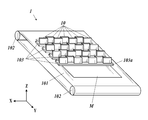
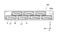
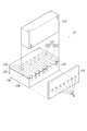
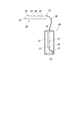
- FIG. 1 It is a figure which shows the schematic structure of the inkjet recording apparatus. It is a schematic diagram which shows the structure of a head unit. It is an exploded perspective view which shows the structure of a head tip. It is a figure which shows the structure for supplying the drive signal to the head chip of the ink ejection head among the inkjet recording apparatus. It is a block diagram which shows the functional structure of an inkjet recording apparatus. It is a figure which shows the example of a drive signal. It is a figure which shows the rate of change of the droplet speed of ink with respect to the number of ejection nozzles when the resistance value R is changed.
- FIG. 1 is a diagram showing a schematic configuration of an inkjet recording device 1 according to an embodiment of the present invention.
- the inkjet recording device 1 includes a transport belt 101, a transport roller 102, a head unit 103, and the like.
- the transport roller 102 is driven by a transport motor (not shown) to rotate about a rotation axis parallel to the X direction in FIG.
- the transport belt 101 is a ring-shaped belt whose inside is supported by a pair of transport rollers 102, and moves around the pair of transport rollers 102 as the transport rollers 102 rotate.
- the recording medium M is moved around the transport belt 101 at a speed corresponding to the rotation speed of the transport roller 102 while the recording medium M is placed on the transport belt 101.
- a transport operation for transporting in the moving direction (Y direction in FIG. 1) is performed.
- the head unit 103 ejects ink from the nozzle N (see FIG. 2) to the recording medium M conveyed by the transfer belt 101 based on the image data, and records the image on the recording medium M.
- four head units 103 corresponding to four colors of ink of yellow (Y), magenta (M), cyan (C), and black (K) are in the transport direction of the recording medium M. They are arranged so as to be arranged at predetermined intervals in order from the upstream side.
- the number of head units 103 may be 3 or less or 5 or more depending on the number of colors used for recording an image.
- FIG. 2 is a schematic view showing the configuration of the head unit 103, and is a plan view of the head unit 103 as viewed from the side facing the transport surface of the transport belt 101.
- Each head unit 103 has a flat plate-shaped base 103a and a plurality of (here, seven) ink ejection heads 10 fixed to the base 103a in a state of being aligned with a hole penetrating the base 103a.
- the ink ejection head 10 has a head chip 12 in which a plurality of nozzles N for ejecting ink are formed, and the nozzle opening surface of the head chip 12 is exposed from the hole portion of the base portion 103a.
- a plurality of nozzles N are one-dimensionally arranged in a direction intersecting the transport direction of the recording medium M (in the present embodiment, a width direction orthogonal to the transport direction, that is, the X direction) to form a nozzle row. ..
- the head chip 12 may be provided with a plurality of nozzle rows so that the positions of the nozzles N are displaced from each other in the X direction.
- the arrangement range of the nozzle N in the X direction covers the width of the recording medium M on the transport belt 101 in the X direction in which an image can be recorded. They are arranged in a houndstooth pattern.
- the inkjet recording device 1 conveys the ink by ejecting ink from the ink ejection head 10 at an appropriate timing according to the image data while the head unit 103 is fixed. An image can be recorded on the recording medium M to be recorded. That is, the inkjet recording device 1 records an image by a single pass method.
- FIG. 3 is an exploded perspective view showing the configuration of the head chip 12.
- the number of nozzles N in the head tip 12 is omitted to be 7, but the head tip 12 of the present embodiment is provided with several hundred to 1,000 or more nozzles N.
- the head chip 12 has a channel substrate 121 in which a plurality of pressure chambers 128 (channels) communicating with the nozzle N are formed corresponding to the plurality of nozzles N.
- a nozzle plate 123 on which a plurality of nozzles N are formed is adhered to the end surface of the channel substrate 121.
- a cover plate 122 is attached to the upper portion of the channel board 121 on the nozzle plate 123 side.
- the channel substrate 121 has a structure in which two substrates 124 and 125 are adhered to each other via an adhesive portion 126.
- the substrates 124 and 125 are made of a piezoelectric material such as lead zirconate titanate (PZT) and are polarized in opposite directions in the thickness direction.
- a plurality of pressure chambers 128 are formed on the channel substrate 121 at equal intervals from each other, and a partition wall 1271 made of a piezoelectric material is formed between the pressure chambers 128.
- An electrode 1272 is provided on the side wall of each pressure chamber 128 (the surface of the partition wall 1271), and the partition wall 1271 is a voltage signal (drive signal) of a drive waveform applied between the electrodes 1272 of the adjacent pressure chamber 128.
- the partition wall 1271 having the electrode 1272 constitutes a piezoelectric element 127 (pressure generating means, actuator) that causes a pressure change in the ink in the pressure chamber 128 and discharges the ink from the nozzle N.
- the ink ejection head 10 of the present embodiment is in a shear mode (shear mode) in which ink is ejected from the nozzle N by shear (shear) stress generated by applying an electric field in a direction orthogonal to the polarization direction of the piezoelectric element. It is an ink ejection head.
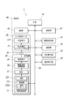
- FIG. 4 is a diagram showing a configuration for supplying a drive signal to the head chip 12 of the ink ejection head 10 in the inkjet recording device 1.
- the inkjet recording device 1 has an ink ejection head 10, a drive unit 20 arranged outside the ink ejection head 10, and a wiring cable 30 (wiring) for electrically connecting the drive unit 20 and the ink ejection head 10. Be prepared.
- the drive unit 20 includes a drive board 21, a drive control unit 22 (drive control means, resistance value control means), a DAC 23 (digital-to-analog conversion unit), a drive waveform amplifier circuit 24 (drive circuit), and a resistance element 25. , The first connector 26 and the like are provided.
- the drive unit 20 outputs a drive signal for driving the piezoelectric element 127 of the ink ejection head 10 at an appropriate timing according to the image data of the recorded image.
- the drive board 21 is a rigid board in which metal routing wiring is formed on the surface of an insulating base material.
- the drive control unit 22, the DAC 23, and the drive waveform amplifier circuit 24 are a group of circuit elements mounted on the drive board 21, generate the above drive signal, and output the drive waveform amplifier circuit 24.
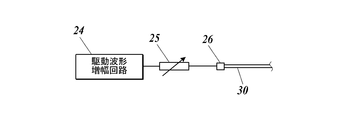
- the resistance element 25 is a terminating resistor connected to the output unit (output terminal) of the drive signal in the drive waveform amplifier circuit 24. That is, the resistance element 25 is provided in the drive signal transmission path between the drive waveform amplifier circuit 24 and the wiring cable 30.
- the resistance element 25 one having an independent circuit component (for example, a lead package or a chip resistor) can be used, but the resistance element 25 is not limited to this, and may be formed in an integrated circuit, for example. ..
- the resistance value of the resistance element 25 has a size corresponding to the length of the wiring cable 30. The method of determining the resistance value of the resistance element 25 will be described in detail later.
- the first connector 26 electrically connects the routing wiring (the transmission path of the signal to which the resistance element 25 is connected) of the drive board 21 and the wiring cable 30.
- the wiring cable 30 is connected to the drive unit 20 via the first connector 26, and is connected to the ink ejection head 10 via the second connector 14.
- the drive signal output from the drive waveform amplifier circuit 24 is transmitted via the wiring cable 30 and applied to the piezoelectric element 127 of the head chip 12.
- the configuration of the wiring cable 30 is not particularly limited, but one in which the periphery of a linear conductor such as a copper wire is covered with an insulating member can be used.
- the ink ejection head 10 includes a housing 11, a head chip 12, a head substrate 13, a second connector 14, an ejection selection switching element 15, a third connector 16, an FPC 17 (Flexible Printed Circuit), and the like.
- the housing 11 internally stores and protects the components of the ink ejection head 10.
- the head tip 12 is fixed to the housing 11 with the nozzle opening surface exposed to the outside.
- the second connector 14 is provided in a state where the connection terminal with the wiring cable 30 is exposed to the outside.
- the head substrate 13 is a rigid substrate in which metal routing wiring is formed on the surface of an insulating base material.
- a second connector 14, a discharge selection switching element 15, and a third connector 16 are mounted on the head substrate 13.
- the wiring of the head substrate 13 includes an input wiring for inputting a drive signal from the second connector 14 to the discharge selection switching element 15, and a piezoelectric element 127 corresponding to each of the plurality of nozzles N from the discharge selection switching element 15.
- a piezoelectric element 127 and a corresponding number of output wirings for outputting a drive signal are included.
- the second connector 14 electrically connects the wiring cable 30 and the input wiring on the head board 13.
- the discharge selection switching element 15 switches whether or not to apply the drive signal input from the input wiring on the head substrate 13 to the piezoelectric element 127 corresponding to each of the plurality of nozzles N. That is, the ejection selection switching element 15 switches whether or not ink is ejected from each nozzle N by not applying a drive signal to the piezoelectric element 127 corresponding to the nozzles that do not eject ink, based on the image data of the recorded image.
- the third connector 16 electrically connects a plurality of output wirings on the head board 13 and a plurality of connection wirings provided on the FPC 17.
- the FPC 17 is provided with a plurality of connection wirings corresponding to the plurality of piezoelectric elements 127, so that each connection wiring is electrically connected to the routing wiring from the piezoelectric element 127 provided on the head chip 12. It is crimped to the head tip 12.
- the drive signal output from the discharge selection switching element 15 to each piezoelectric element 127 is sent to the corresponding piezoelectric element via the output wiring on the head substrate 13, the connection wiring on the FPC 17, and the routing wiring in the head chip 12. It is applied to 127.
- FIG. 5 is a block diagram showing a functional configuration of the inkjet recording device 1.
- the inkjet recording device 1 includes a control unit 40, a transfer control unit 51, a communication unit 52, an operation display unit 53, a temperature detection unit 54, the above-mentioned ink ejection head 10, a drive unit 20, a wiring cable 30, and the like. These are connected so that signals can be transmitted and received via the bus 55.
- the control unit 40 comprehensively controls the overall operation of the inkjet recording device 1.
- the control unit 40 includes a CPU 41 (Central Processing Unit), a RAM 42 (Random Access Memory), a storage unit 43, and the like.
- the CPU 41 reads out the control program stored in the storage unit 43 and performs various control processes related to image recording and its setting.
- the RAM 42 provides the CPU 41 with a working memory space and stores temporary data.
- the storage unit 43 includes a non-volatile memory for storing control programs, setting data, and the like. Further, the storage unit 43 may include a DRAM or the like that temporarily stores settings related to an image recording command (print job) acquired from the outside via the communication unit 52, image data of recorded images, and the like.
- the transfer control unit 51 operates a motor that rotates the transfer roller 102 to rotate the transfer roller 102 at an appropriate speed and timing.
- the transfer control unit 51 may have the same configuration as the control unit 40.
- the communication unit 52 transmits / receives data to / from an external device according to a predetermined communication standard.
- the communication unit 52 includes a connection terminal according to the communication standard to be used, driver hardware (network card) related to the communication connection, and the like.
- the operation display unit 53 displays status information and menus related to image recording, and accepts input operations from the user.
- the operation display unit 53 includes, for example, a display screen by a liquid crystal panel, a driver of the liquid crystal panel, a touch panel provided on the liquid crystal screen, and the like, and corresponds to the position where the touch operation is performed by the user and the type of operation.
- the operation detection signal is output to the control unit 40.
- the temperature detection unit 54 is attached to the ink ejection head 10 or provided in the vicinity of the ink ejection head 10, detects the temperature corresponding to the temperature of the ink ejection head 10, and outputs the detection result to the control unit 40. ..
- the drive control unit 22 of the drive unit 20 controls the operation of each unit of the drive unit 20 according to the content of the image data of the recorded image.
- the drive control unit 22 includes a CPU 221 and a storage unit 222 and the like.
- the storage unit 222 holds in advance the waveform pattern 222a of the drive signal for ejecting ink from the nozzle N as digital discrete value array data.
- the CPU 221 applies a drive voltage having an appropriate waveform pattern to the piezoelectric element 127 according to whether or not ink is ejected from each nozzle N based on the image data of the recorded image stored in the storage unit 222 or the storage unit 43.
- the waveform pattern data (digital waveform data) corresponding to the waveform pattern for the purpose is selected and output to the DAC 23 at an appropriate timing according to the clock signal (not shown).
- the DAC 23 converts the waveform pattern data of the drive waveform input from the drive control unit 22 into analog, and outputs the obtained analog signal (drive signal) to the drive waveform amplifier circuit 24.
- the drive waveform amplifier circuit 24 performs an amplification operation (voltage amplification and then current amplification) of the drive signal input from the DAC 23, and outputs the amplified drive signal.
- the drive signal output from the drive waveform amplifier circuit 24 is transmitted to the ink ejection head 10 via the transmission path provided with the resistance element 25 and the wiring cable 30.
- one pixel of a recorded image is formed by coalescing a plurality of ink droplets continuously ejected from a nozzle N and landing them on a recording medium M. It is also possible to adjust the pixel density (gradation) by changing the number of ink droplets to be combined. It should be noted that the plurality of ink droplets before coalescence may be in a state of being connected by a columnar ink (ink liquid column) or in a state of being separated from each other.
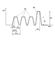
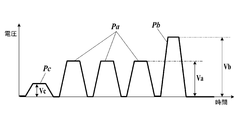
- FIG. 6 is a diagram showing an example of a drive signal used in the present embodiment.
- the drive signal of FIG. 6 includes three first pulse signals Pa and one second pulse signal Pb applied after these first pulse signals Pa.
- any one of the first pulse signal Pa and the second pulse signal Pb will be referred to as “pulse signal P”.
- the pulse signal P is a trapezoidal wave voltage signal.
- the piezoelectric element 127 (partition wall 1271) is shear-deformed in the direction in which the pressure chamber 128 expands (the direction in which the volume increases), resulting in a trapezoidal shape.
- the piezoelectric element 127 (partition wall 1271) is shear-deformed in the direction in which the pressure chamber 128 contracts (the direction in which the volume decreases).
- the voltage amplitude of the first pulse signal Pa is Va, and the time (pulse width) from the start of the rise of the trapezoidal wave to the start of the fall is 1.3AL.
- AL Acoustic Length
- the rise time T1 and the fall time T2 of the trapezoidal wave of the first pulse signal Pa are 1 ⁇ s.
- the three first pulse signals Pa are applied with a pulse period of 2AL.
- the voltage amplitude of the second pulse signal Pb is Vb, and the pulse width is AL.
- the voltage amplitude Va of the first pulse signal Pa is adjusted to a value smaller than the voltage amplitude Vb of the second pulse signal Pb. This is to suppress the difference in ink speed when the number of droplets of ink continuously ejected from different nozzles N is different from each other. That is, the first pulse signal Pa is added to continuously eject two or more ink droplets from the ink speed when a single ink droplet is ejected only by the second pulse signal Pb. Where the ink speed tends to be faster when the ink is flushed, the voltage amplitude Va of the first pulse signal Pa is made smaller than the voltage amplitude Vb, and the droplet speed of the ink ejected by the first pulse signal Pa is set. By lowering the ink droplet speed, the ink droplet velocity when two or more ink droplets are continuously ejected can be suppressed, and the speed difference can be reduced.
- the drive signal applied to each piezoelectric element 127 is adjusted so that ink droplets are ejected from the nozzle N at a desired speed and a desired volume (ink amount).
- the waveform of the drive signal is distorted due to the capacitance of the piezoelectric element 127, the inductance and resistance of the drive signal transmission path, and the like.
- the waveform of the drive signal is distorted, the droplet velocity and volume of the ink ejected from the nozzle N deviate from the desired values, and the landing position on the recording medium M and the amount of landing liquid vary, leading to deterioration of image quality. ..
- the drive waveform amplifier circuit 24 that outputs the drive signal is provided outside the ink ejection head 10
- the drive signal transmission path (mainly the wiring cable 30) is long. Therefore, the inductance and resistance are increasing. Therefore, variations in ink droplet velocity and volume due to the inductance and resistance of the drive signal transmission path, particularly the wiring cable 30, cannot be ignored.
- the inductance of the wiring cable 30 becomes large, overshoot or undershoot occurs in the drive signal, distortion from a desired waveform becomes large, and the ink droplet velocity and volume deviate from the desired values.
- the speed of the ink is usually lowered by the distortion of the waveform, but it may be higher than the desired value depending on how the waveform is distorted.
- the change width of the droplet speed when the number of piezoelectric elements 127 whose drive signal application periods overlap, that is, the number of nozzles N for ejecting ink (the number of ejection nozzles) at a common timing is also changed is also the wiring cable 30. It can change depending on the inductance of. The larger the change width of the droplet velocity with respect to the number of ejection nozzles, the more remarkable the deterioration of the image quality of the recorded image becomes.
- the resistance element 25 in the output portion of the drive waveform amplifier circuit 24, the occurrence of overshoot and undershoot due to the inductance of the wiring cable 30 is suppressed, and the distortion of the waveform of the drive signal is suppressed.
- the resistance value R of the resistance element 25 is set to a size corresponding to the length of the wiring cable 30.
- the resistance value R of the resistance element 25 is determined so that the change width (range) of the ink droplet speed when the number of ejection nozzles is changed satisfies a predetermined change width suppression condition.
- the change width suppressing condition can be that the change width of the ink droplet velocity when the number of ejection nozzles is changed is the smallest.
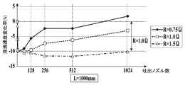
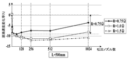
- FIGS. 7A to 7C are diagrams showing the rate of change in the droplet speed of the ink with respect to the number of ejection nozzles when the resistance value R is changed. Specifically, when the resistance value R of the resistance element 25 is 0.75 ⁇ , 1.0 ⁇ , and 1.5 ⁇ , ink is ejected from the nozzle N using the same drive signal, and the number of ejection nozzles is up to 1024 nozzles. It is a graph which plotted the rate of change of the droplet velocity of ink when it changed stepwise.
- the reference value of the droplet velocity change rate can be, for example, the droplet velocity of ink when ink is ejected from a single nozzle N by a drive signal without distortion.
- the candidate value of the resistance value R is preferably selected within a range in which the relationship of CR ⁇ 500ns is satisfied when the capacitance of the capacitive load of the plurality of piezoelectric elements 127 of the ink ejection head 10 is C.
- FIG. 7A is a diagram showing the rate of change in the droplet velocity of ink when the length of the wiring cable 30 (hereinafter referred to as the wiring length L) is 1000 mm.
- the range of the droplet velocity change rate (change width of the droplet velocity) is the smallest when the resistance value R of the resistance element 25 is 1.0 ⁇ . Therefore, when the wiring length L is 1000 mm, the resistance value R is set to 1.0 ⁇ .
- FIG. 7B is a diagram showing the rate of change in the droplet velocity of ink when the wiring length L of the wiring cable 30 is 700 mm.
- the range of the rate of change in droplet velocity is the smallest when the resistance value R of the resistance element 25 is 0.75 ⁇ . Therefore, when the wiring length L is 700 mm, the resistance value R is set to 0.75 ⁇ .
- FIG. 7C is a diagram showing the rate of change in the droplet velocity of ink when the wiring length L of the wiring cable 30 is 500 mm.
- the range of the rate of change in droplet velocity is the smallest when the resistance value R of the resistance element 25 is 0.75 ⁇ . Therefore, when the wiring length L is 500 mm, the resistance value R is set to 0.75 ⁇ .
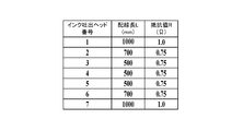
- FIG. 8 is a diagram showing a setting example of the resistance value R of the resistance element 25 in the plurality of ink ejection heads 10.
- FIG. 8 shows the wiring length L of the wiring cable 30 connected to each of the first to seventh ink ejection heads 10 and the resistance value R of the resistance element 25 determined according to the wiring length L. ing.
- the wiring length L of the wiring cable 30 connected to the first and seventh ink ejection heads 10 is 1000 mm, and the resistance value R of the first and seventh ink ejection heads 10 accordingly. Is set to 1.0 ⁇ .
- the wiring length L of the wiring cable 30 connected to the second and sixth ink ejection heads 10 is 700 mm
- the wiring length L of the wiring cable 30 connected to the third to fifth ink ejection heads 10 is 500 mm. Therefore, the resistance values R of the second to sixth ink ejection heads 10 are set to 0.75 ⁇ accordingly.
- FIG. 8 is an example of setting the resistance value R according to the wiring length L of the wiring cable 30, and is not intended to be limited to this.
- the resistance values R of the resistance elements 25 in all the ink ejection heads 10 may be different from each other, or all have the same resistance value R. It may be.
- the method for determining the resistance value R of the resistance element 25 is not limited to that shown in FIGS. 7A to 7C, and is in the range of the number of ejection nozzles that frequently appears when recording an image (for example, in FIGS. 7A to 7C).
- the resistance value R may be set so that the range of the rate of change in the droplet velocity in the range of 128 to 1024 discharge nozzles, etc.) is the narrowest. That is, the above-mentioned change width suppressing condition may be such that the change width of the ink droplet speed in a predetermined number of ejection nozzles range is the smallest. For example, in the example of FIGS.
- the wiring length L 1000 mm, 700 mm, or 500 mm can be used.
- the resistance value R is set to 1.5 ⁇ .
- the resistance value R of the resistance element 25 is determined as described above, and the drive signal is further adjusted (corrected) according to the number of ejection nozzles.
- the number of discharge nozzles changes, the number of piezoelectric elements 127 to which the drive signal is applied, that is, the capacitive drive load increases or decreases, so that the distortion of the drive signal (for example, how the waveform rises and falls becomes dull) changes.
- the droplet speed and volume of the ejected ink fluctuate.
- by adjusting the drive signal according to the number of ejection nozzles it is possible to suppress the change in the distortion of the drive waveform and stabilize the droplet speed and volume of the ink regardless of the number of ejection nozzles.
- the voltage amplitude of the pulse signal of the drive waveform is adjusted according to the number of discharge nozzles.
- the droplet speed of the ejected ink can be increased.
- the pulse width of the pulse signal of the drive waveform may be adjusted according to the number of discharge nozzles.
- adjustment may be made to add a sub-pulse signal Pc for swinging the liquid level of the ink in the nozzle N before the first pulse signal Pa and the second pulse signal Pb. ..
- the sub-pulse signal Pc has a voltage amplitude Vc smaller than the voltage amplitude Va of the first pulse signal Pa.
- the droplet velocity and volume of the ink can be adjusted according to the relationship between the phase of the fluctuation of the liquid surface according to the sub-pulse signal Pc and the phase of the pressure fluctuation due to the pulse signal P. Further, the voltage amplitude and pulse width of the sub-pulse signal Pc may be further adjusted according to the number of ejection nozzles. Further, the rise time T1 of the pulse signal P may be adjusted to be longer as the number of discharge nozzles is smaller, and the fall time T2 of the pulse signal P may be longer as the number of discharge nozzles is smaller. Is also good. Further, as the number of discharge nozzles is smaller, both the rise time T1 and the fall time T2 may be adjusted to be longer. The adjustment range of the rise time T1 and the fall time T2 can be, for example, about 0 ⁇ s to 2 ⁇ s.
- the drive signal is adjusted by the drive control unit 22. That is, the drive control unit 22 specifies the number of ejection nozzles of the ink ejection head 10 based on the line data of the image data input from the control unit 40, and transmits the waveform pattern data adjusted according to the identification result to the DAC 23. Output.
- the adjusted waveform pattern data corresponding to the number of discharge nozzles is registered in advance in the waveform pattern 222a of the storage unit 222, and the drive control unit 22 selects the corresponding waveform pattern data according to the number of discharge nozzles. It may be output to DAC23.
- the voltage amplitude, the pulse width, the adjustment amount of the rise time T1 and the fall time T2 according to the number of discharge nozzles, and the setting of the presence / absence of the sub-pulse signal Pc are registered in the storage unit 222 or the storage unit 43.
- the drive control unit 22 may generate and output the adjusted drive waveform each time based on the number of discharge nozzles and the above settings.
- FIG. 10 is a diagram showing a partial configuration of the ink ejection head 10 according to the first modification.
- a variable resistor is used as the resistance element 25.
- the configuration of the variable resistor is not particularly limited, but for example, it has a contact that can slide on the resistor, and the resistance value R can be adjusted by changing the position of the contact according to the rotation of the adjustment shaft. Can be used. Further, the resistance value R is not limited to the one that can be continuously adjusted, and the resistance value R may be changed stepwise.
- Modification 2 Next, a modification 2 of the above embodiment will be described. This modification is different from the above embodiment in that the drive control unit 22 can change the resistance value R of the resistance element 25. Hereinafter, the differences from the above-described embodiment will be described.
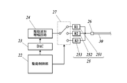
- FIG. 11 is a diagram showing a partial configuration of the ink ejection head 10 according to the second modification.
- the resistance element 25 of this modification includes a first resistance element 251 having a resistance value R1, a second resistance element 252 having a resistance value R2, and a third resistance element 253 having a resistance value R3, and these resistances.
- the elements are provided in parallel and connected to the first connector 26.
- a switching element 27 for electrically connecting the drive waveform amplifier circuit 24 and any one of the first resistance element 251 and the second resistance element 252 and the third resistance element 253 is provided. The connection state by the switching element 27 can be changed and controlled by the drive control unit 22.
- the drive control unit 22 can change the resistance value R of the resistance element 25 among the three different resistance values R1, R2, and R3.
- the drive control unit 22 of this modification constitutes a resistance value control means.
- the resistance element 25 may be capable of selecting the resistance value R from two or four or more different values.
- the drive control unit 22 changes the resistance value R of the resistance element 25 each time a drive signal is applied so that the resistance value R of the resistance element 25 becomes a value corresponding to the number of ejection nozzles. adjust. That is, the drive control unit 22 specifies the number of ejection nozzles of the ink ejection head 10 based on the line data of the image data input from the control unit 40, and changes the resistance value R of the resistance element 25 according to the identification result. To do. For example, the resistance value R of the resistance element 25 corresponding to the number of discharge nozzles is registered in the storage unit 222 or the storage unit 43 in advance, and the drive control unit 22 switches elements so that the resistance value R corresponds to the number of discharge nozzles. The connection state of 27 is switched.
- the drive control unit 22 may adjust the resistance value R of the resistance element 25 according to the temperature detection result by the temperature detection unit 54 in addition to the number of discharge nozzles. Since the capacitance of the piezoelectric element 127 and the resistance of the wiring cable 30 change according to the temperature, changes in these capacitances and resistances lead to distortion of the drive signal depending on the fluctuation range of the temperature. Therefore, by adjusting the resistance value R according to the temperature detection result, it is possible to suppress the distortion of the drive signal and more effectively stabilize the speed and volume of the ink. For example, as the temperature rises, the capacitance C of the piezoelectric element 127 increases. Therefore, by reducing the resistance value R of the resistance element 25 accordingly, distortion of the drive signal can be effectively suppressed.
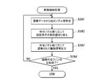
- FIG. 12 is a flowchart showing a control procedure by the drive control unit 22 of the drive control process according to the second modification.
- the drive control process is started with the start of the image recording operation by the inkjet recording device 1.
- the drive control unit 22 specifies the number of nozzles used for recording the line to be recorded in the image, that is, the number of ejection nozzles, based on the image data input from the control unit 40. (Step S101).
- the drive control unit 22 switches the resistance value R of the resistance element 25 according to the specified number of discharge nozzles (step S102). That is, the drive control unit 22 outputs a control signal to the switching element 27 so that the resistance value R of the resistance element 25 becomes a value corresponding to the specified number of ejection nozzles, and the drive waveform is amplified by the switching element 27.
- the resistance element to be connected to the circuit 24 is switched.
- the drive control unit 22 outputs a drive signal adjusted according to the specified number of ejection nozzles from the drive waveform amplifier circuit 24, and ejects ink from each nozzle N (step S103).
- the drive control unit 22 returns the process to step S101 when the recording of all lines of the image to be recorded has not been completed (“NO” in step S104), and when the recording of all lines is completed (“NO”). In step S104, “YES”), the drive control process is terminated.
- the inkjet recording device 1 of the present embodiment causes a pressure change in the nozzle N for ejecting ink, the pressure chamber 128 communicating with the nozzle N, and the ink in the pressure chamber 128 in response to the application of a drive signal.
- An ink ejection head 10 having a piezoelectric element 127 for ejecting ink from the nozzle N, and a drive waveform amplification circuit 24 as a drive circuit arranged outside the ink ejection head 10 and outputting a drive signal are provided.
- a wiring cable 30 that electrically connects the drive unit 20, the drive unit 20 and the ink ejection head 10 and transmits a drive signal output from the drive waveform amplification circuit 24 and applied to the piezoelectric element 127 is provided.
- the drive unit 20 has a resistance element 25 provided in a drive signal transmission path between the drive waveform amplification circuit 24 and the wiring cable 30, and the resistance value R of the resistance element 25 is the wiring length of the wiring cable 30.
- the size corresponds to L.
- the drive waveform amplifier circuit 24 is arranged outside the ink ejection head 10 in this way, there arises a problem that the drive signal is distorted due to the inductance of the wiring cable 30 and the droplet velocity and volume of the ink deviate from the desired values.
- the resistance element 25 and setting the resistance value R to a size corresponding to the wiring length L of the wiring cable 30, overshoot and undershoot of the drive signal due to the inductance of the wiring cable 30 can be appropriately suppressed.
- Distortion of the waveform of the drive signal can be suppressed.
- fluctuations in ink droplet velocity and volume due to the inductance of the wiring cable 30 can be suppressed.
- the change width of the ink droplet velocity when the number of ejection nozzles is changed depends on the combination of the wiring length L of the wiring cable 30 and the resistance value R of the resistance element 25, the wiring length L of the wiring cable 30
- the change width of the ink droplet velocity with respect to the number of ejection nozzles can be suppressed to be small. As a result, deterioration of image quality can be effectively suppressed.
- the resistance element 25 of the modification 2 and the modification 3 is provided in a state where the resistance value R can be changed. According to this, the resistance value R can be easily adjusted when the wiring length L of the wiring cable 30 is changed or when the ink ejection head 10 is replaced.
- the inkjet recording device 1 of the modification 2 includes a drive control unit 22 as a resistance value control means for changing the resistance value R of the resistance element 25. According to this, the resistance value R of the resistance element 25 can be changed inside the inkjet recording device 1. Therefore, since the user can change the resistance value R without exchanging the resistance element 25 or directly adjusting the resistance value R, the user convenience can be improved.
- the ink ejection head 10 has a plurality of nozzles N, a plurality of pressure chambers 128 corresponding to the plurality of nozzles N, and a plurality of piezoelectric elements 127 corresponding to the plurality of nozzles N.
- the resistance value R of the resistance element 25 has a size corresponding to the number of ejection nozzles (the number of nozzles N that eject ink at a common timing among a plurality of nozzles N). As described above, the resistance value R of the resistance element 25 is adjusted each time a drive signal is applied. According to this, fluctuations in the ink droplet velocity and volume according to the number of ejection nozzles can be suppressed by adjusting the resistance value R of the resistance element 25. Therefore, the deterioration of the image quality can be suppressed more effectively.
- the inkjet recording device 1 of the second modification includes a temperature detection unit 54 that detects a temperature corresponding to the temperature of the ink ejection head 10, and the drive control unit 22 is based on the temperature detected by the temperature detection unit 54.
- the resistance value R of the resistance element 25 is adjusted. According to this, it is possible to suppress the distortion of the drive waveform caused by the fluctuation of the resistance value of the piezoelectric element 127 due to the temperature and the fluctuation of the resistance of the wiring cable 30.
- the resistance value R is set within the range where the relationship of CR ⁇ 500ns is satisfied, so that the drive signal can be obtained. It is possible to suppress distortion of the drive signal due to the inductance of the wiring cable 30 while suppressing fluctuations in the droplet velocity and volume of the ink due to the dull rise and fall of the waveform.
- the ink liquid with respect to the number of discharge nozzles is determined.
- the change width of the drip velocity can be suppressed to a small value, and the deterioration of the image quality can be effectively suppressed.
- the inkjet recording device 1 includes a plurality of ink ejection heads 10, a plurality of drive units 20 corresponding to the plurality of ink ejection heads 10, and a plurality of wiring cables 30 corresponding to the plurality of ink ejection heads 10.
- the resistance value R of the resistance element 25 possessed by each of the plurality of drive units 20 has a size corresponding to the wiring length L of the wiring cable 30 connected to the drive unit 20. According to this, in a configuration in which a plurality of ink ejection heads 10 and a plurality of drive units 20 are connected by using wiring cables 30 having different wiring lengths L, the recorded images are recorded by each ink ejection head 10. It is possible to effectively suppress the deterioration of the image quality of each part.
- the inkjet recording device 1 includes a drive control unit 22 as a drive control means for controlling the output operation of the drive signal by the drive waveform amplifier circuit 24, the drive signal includes a pulse signal P, and the drive control unit 22 discharges.
- the voltage amplitude of the pulse signal P is adjusted according to the number of nozzles. According to this, the distortion of the drive signal due to the change in the number of discharge nozzles, that is, the number of piezoelectric elements 127 having overlapping drive signal application periods, and the increase or decrease in the capacitive drive load (for example, the rise of the waveform) It is possible to suppress the dullness of the fall). Therefore, the droplet speed and volume of the ejected ink can be stabilized regardless of the number of ejection nozzles.
- the drive control unit 22 adjusts the pulse width of the pulse signal P according to the number of discharge nozzles. By adjusting the pulse width, the droplet speed and volume of the ejected ink can be finely adjusted. Therefore, when the number of ejection nozzles is changed, the droplet velocity and volume of the ejected ink can be further stabilized.
- the drive control unit 22 amplifies the drive waveform including the sub-pulse signal Pc for swinging the liquid level of the ink in the nozzle N and the pulse signal P applied following the sub-pulse signal Pc. It is output by the circuit 24. According to this, the droplet speed and volume of the ink can be adjusted according to the relationship between the phase of the fluctuation of the liquid surface according to the sub-pulse signal Pc and the phase of the pressure fluctuation due to the pulse signal P. Therefore, when the number of ejection nozzles is changed, the droplet velocity and volume of the ejected ink can be further stabilized.
- the drive control unit 22 adjusts the waveform of the drive signal so that at least one of the rise time T1 and the fall time T2 of the pulse signal P becomes longer as the number of discharge nozzles decreases.
- the drive control unit 22 outputs a drive signal including a plurality of pulse signals P by the drive waveform amplifier circuit 24, and the piezoelectric element 127 outputs one pixel on the recording medium M in response to the plurality of pulse signals P.
- a plurality of ink droplets to be formed are ejected from the nozzle N. According to this, an image can be recorded by a multi-drop method in which the pixel density is adjusted according to the number of ink droplets. Further, since the droplet velocity and volume of each ink can be stabilized by adjusting the resistance value R of the resistance element 25, the droplets of a plurality of inks can be appropriately coalesced to a desired position on the recording medium M. It can be landed.
- the ink caused by the inductance of the wiring cable 30 It is possible to suppress fluctuations in droplet velocity and volume, and effectively suppress deterioration in image quality.
- the resistance value R of the resistance element 25 becomes a size corresponding to the wiring length L of the wiring cable 30, and the resistance value R corresponds to the number of ejection nozzles.
- the resistance value R of the resistance element 25 is adjusted each time a drive signal is applied so that the size corresponds to the number of nozzles N for ejecting ink. According to this, fluctuations in the ink droplet velocity and volume according to the number of ejection nozzles can be suppressed by adjusting the resistance value R of the resistance element 25. Therefore, the deterioration of the image quality can be suppressed more effectively.
- the present invention is not limited to the above embodiment, and various modifications can be made.
- the wiring cable 30 has been described as an example of wiring, but the present invention is not limited to this, and any other wiring such as FPC may be used.
- the drive control unit 22 may be realized by the control unit 40.
- the drive control unit 22 and the control unit 40 configure the drive control means and the resistance value control means.
- the "number of piezoelectric elements 127 whose drive signal application periods overlap" in the above embodiment is not necessarily limited to the number of piezoelectric elements 127 whose drive signal application start timings are simultaneous, and the drive signal application period is at least.
- the number of partially overlapping piezoelectric elements 127 may be used. Therefore, the "number of nozzles N that eject ink at a common timing (number of ejection nozzles)" is not limited to the number of nozzles N that eject ink at the same time, and the piezoelectric element 127 in which the application periods of drive signals overlap at least partially. It may be the number of nozzles N corresponding to.
- the multi-drop method in which one pixel is formed by a plurality of ink droplets has been described as an example, but the present invention is not limited to this, and one pixel is formed by a single ink droplet.
- the present invention may be applied to the formed inkjet recording device.
- the adjustment of the drive signal according to the number of ejection nozzles may be omitted.
- the shear mode ink ejection head 10 has been described as an example, but the present invention is not limited to this.
- the present invention is applied to an ink ejection head in a vent mode in which a piezoelectric element (pressure generating means) fixed to a wall surface of a pressure chamber is deformed to cause a pressure change in the ink in the pressure chamber to eject the ink. May be applied.
- a piezoelectric element pressure generating means
- another pressure generating portion capable of converting heat, electromagnetism, or the like into spatial deformation to exert a pressure change on the ink in the pressure chamber may be used.
- the recording medium M is conveyed by the conveying belt 101
- the recording medium M is held and conveyed on the outer peripheral surface of the rotating conveying drum. Is also good.
- the single-pass type inkjet recording device 1 has been described as an example, but the present invention may be applied to an inkjet recording device that records an image while scanning the ink ejection head 10.
- the present invention can be used for an inkjet recording device, an adjustment method for an inkjet recording device, and a control method for an inkjet recording device.
- Ink ejection recording device 10 Ink ejection head 11 Housing 12 Head chip 13 Head substrate 14 Second connector 15 Discharge selection switching element 16 Third connector 17 FPC 20 Drive unit 21 Drive board 22 Drive control unit (drive control means, resistance value control means) 23 DAC 24 Drive waveform amplifier circuit (drive circuit) 25 Resistance element 26 First connector 27 Switching element 30 Wiring cable (wiring) 40 Control unit 54 Temperature detection unit 101 Conveyance belt 102 Conveyance roller 103 Head unit 121 Channel substrate 122 Cover plate 123 Nozzle plate 127 Piezoelectric element (pressure generating means) 1271 Partition 1272 Electrode 128 Pressure chamber M Recording medium N Nozzle P, Pa, Pb Pulse signal Pc Secondary pulse signal R Resistance value
Landscapes
- Particle Formation And Scattering Control In Inkjet Printers (AREA)
- Ink Jet (AREA)
Abstract
画質の低下を効果的に抑制することができるインクジェット記録装置、インクジェット記録装置の調整方法及びインクジェット記録装置の制御方法を提供する。インクジェット記録装置は、インクを吐出するノズルと、ノズルに連通する圧力室と、駆動信号の印加に応じて圧力室のインクに圧力変化を生じさせてノズルからインクを吐出させる圧力発生手段と、を有するインク吐出ヘッドと、インク吐出ヘッドの外部に配置され、駆動信号を出力する駆動回路が設けられた駆動部と、駆動部とインク吐出ヘッドとを電気的に接続し、駆動回路から出力されて圧力発生手段に印加される駆動信号が伝送される配線と、を備え、駆動部は、駆動回路と配線との間の駆動信号の伝送経路に設けられた抵抗素子を有し、抵抗素子の抵抗値が、配線の長さに応じた大きさとなっている。
Description
本発明は、インクジェット記録装置、インクジェット記録装置の調整方法及びインクジェット記録装置の制御方法に関する。
従来、インク吐出ヘッドに設けられたノズルからインクを吐出させて所望の位置に着弾させることで画像を記録するインクジェット記録装置がある。インク吐出ヘッドには、ノズルに連通する圧力室と、駆動信号の印加に応じて圧力室のインクに圧力変化を生じさせる圧力発生部と、が設けられており、圧力発生部が圧力室のインクに圧力変化を生じさせることでノズルからインクが吐出される。圧力発生部としては、例えば圧電素子が用いられ、この圧電素子に適切な電圧を印加することで圧力室の変形量や変形時間が制御される。画像の記録時には、インク吐出ヘッドにおいて多数配列されたノズルに各々対応する圧電素子のうち、駆動信号を印加する圧電素子を記録画像に応じて選択することで、各ノズルからのインクの吐出有無が切り替えられる。
圧電素子は、容量性の負荷であり、駆動信号の印加期間が重複する圧電素子の数(すなわち、共通するタイミングでインクを吐出するノズルの数。以下、吐出ノズル数と記す)に応じて駆動負荷が変動する。このため、吐出ノズル数が増大すると駆動信号の波形が不安定となり、ノズルから吐出されるインクの速度や体積が所望の値から変動して画質の低下に繋がる問題がある。
これに対し、吐出ノズル数に応じて駆動信号の波形を調整することで駆動負荷の変動に起因する画質の低下を抑制する技術がある(例えば、特許文献1)。
これに対し、吐出ノズル数に応じて駆動信号の波形を調整することで駆動負荷の変動に起因する画質の低下を抑制する技術がある(例えば、特許文献1)。
しかしながら、駆動信号を出力する駆動回路がインク吐出ヘッドの外部に設けられている場合には、駆動信号の伝送経路が長くなり、この伝送経路のインダクタンスによっても駆動信号の波形が不安定となり得る。よって、単に吐出ノズル数に応じて駆動信号の波形を調整したのでは、ノズルから吐出されるインクの速度や体積の変動を十分に抑えられず、画質の低下を効果的に抑制することができないという課題がある。
この発明の目的は、画質の低下を効果的に抑制することができるインクジェット記録装置、インクジェット記録装置の調整方法及びインクジェット記録装置の制御方法を提供することにある。
上記目的を達成するため、請求項1に記載のインクジェット記録装置の発明は、
インクを吐出するノズルと、前記ノズルに連通する圧力室と、駆動信号の印加に応じて前記圧力室のインクに圧力変化を生じさせて前記ノズルからインクを吐出させる圧力発生手段と、を有するインク吐出ヘッドと、
前記インク吐出ヘッドの外部に配置され、前記駆動信号を出力する駆動回路が設けられた駆動部と、
前記駆動部と前記インク吐出ヘッドとを電気的に接続し、前記駆動回路から出力されて前記圧力発生手段に印加される前記駆動信号が伝送される配線と、
を備え、
前記駆動部は、前記駆動回路と前記配線との間の前記駆動信号の伝送経路に設けられた抵抗素子を有し、
前記抵抗素子の抵抗値が、前記配線の長さに応じた大きさとなっている。
インクを吐出するノズルと、前記ノズルに連通する圧力室と、駆動信号の印加に応じて前記圧力室のインクに圧力変化を生じさせて前記ノズルからインクを吐出させる圧力発生手段と、を有するインク吐出ヘッドと、
前記インク吐出ヘッドの外部に配置され、前記駆動信号を出力する駆動回路が設けられた駆動部と、
前記駆動部と前記インク吐出ヘッドとを電気的に接続し、前記駆動回路から出力されて前記圧力発生手段に印加される前記駆動信号が伝送される配線と、
を備え、
前記駆動部は、前記駆動回路と前記配線との間の前記駆動信号の伝送経路に設けられた抵抗素子を有し、
前記抵抗素子の抵抗値が、前記配線の長さに応じた大きさとなっている。
請求項2に記載の発明は、請求項1に記載のインクジェット記録装置において、
前記抵抗素子は、抵抗値を変更することが可能な状態で設けられている。
前記抵抗素子は、抵抗値を変更することが可能な状態で設けられている。
請求項3に記載の発明は、請求項2に記載のインクジェット記録装置において、
前記抵抗素子の抵抗値を変更する抵抗値制御手段を備える。
前記抵抗素子の抵抗値を変更する抵抗値制御手段を備える。
請求項4に記載の発明は、請求項3に記載のインクジェット記録装置において、
前記インク吐出ヘッドは、複数の前記ノズルと、前記複数のノズルに対応する複数の前記圧力室と、前記複数のノズルに対応する複数の前記圧力発生手段と、を有し、
前記抵抗値制御手段は、前記抵抗素子の抵抗値が、前記複数のノズルのうち共通するタイミングでインクを吐出するノズルの数に応じた大きさとなるように、前記駆動信号が印加されるごとに前記抵抗素子の抵抗値を調整する。
前記インク吐出ヘッドは、複数の前記ノズルと、前記複数のノズルに対応する複数の前記圧力室と、前記複数のノズルに対応する複数の前記圧力発生手段と、を有し、
前記抵抗値制御手段は、前記抵抗素子の抵抗値が、前記複数のノズルのうち共通するタイミングでインクを吐出するノズルの数に応じた大きさとなるように、前記駆動信号が印加されるごとに前記抵抗素子の抵抗値を調整する。
請求項5に記載の発明は、請求項3又は4に記載のインクジェット記録装置において、
前記インク吐出ヘッドの温度に対応する温度を検出する温度検出部を備え、
前記抵抗値制御手段は、前記温度検出部により検出された温度に基づいて前記抵抗素子の抵抗値を調整する。
前記インク吐出ヘッドの温度に対応する温度を検出する温度検出部を備え、
前記抵抗値制御手段は、前記温度検出部により検出された温度に基づいて前記抵抗素子の抵抗値を調整する。
請求項6に記載の発明は、請求項1から5のいずれか一項に記載のインクジェット記録装置において、
前記インク吐出ヘッドは、複数の前記ノズルと、前記複数のノズルに対応する複数の前記圧力室と、前記複数のノズルに対応する複数の前記圧力発生手段と、を有し、
前記複数の圧力発生手段の容量性負荷の容量をC、前記抵抗素子の抵抗値をRとした場合に、前記抵抗素子の抵抗値は、CR<500nsの関係が満たされる範囲内で定められている。
前記インク吐出ヘッドは、複数の前記ノズルと、前記複数のノズルに対応する複数の前記圧力室と、前記複数のノズルに対応する複数の前記圧力発生手段と、を有し、
前記複数の圧力発生手段の容量性負荷の容量をC、前記抵抗素子の抵抗値をRとした場合に、前記抵抗素子の抵抗値は、CR<500nsの関係が満たされる範囲内で定められている。
請求項7に記載の発明は、請求項1から6のいずれか一項に記載のインクジェット記録装置において、
前記インク吐出ヘッドは、複数の前記ノズルと、前記複数のノズルに対応する複数の前記圧力室と、前記複数のノズルに対応する複数の前記圧力発生手段と、を有し、
前記複数のノズルのうち共通するタイミングでインクを吐出するノズルの数を変化させたときのインクの液滴速度の変化幅が、所定の変化幅抑制条件を満たすように前記抵抗素子の抵抗値が定められている。
前記インク吐出ヘッドは、複数の前記ノズルと、前記複数のノズルに対応する複数の前記圧力室と、前記複数のノズルに対応する複数の前記圧力発生手段と、を有し、
前記複数のノズルのうち共通するタイミングでインクを吐出するノズルの数を変化させたときのインクの液滴速度の変化幅が、所定の変化幅抑制条件を満たすように前記抵抗素子の抵抗値が定められている。
請求項8に記載の発明は、請求項1から7のいずれか一項に記載のインクジェット記録装置において、
複数の前記インク吐出ヘッドと、
前記複数のインク吐出ヘッドに対応する複数の前記駆動部と、
前記複数のインク吐出ヘッドに対応する複数の前記配線と、
を備え、
前記複数の駆動部の各々が有する前記抵抗素子の抵抗値が、当該駆動部に接続されている前記配線の長さに応じた大きさとなっている。
複数の前記インク吐出ヘッドと、
前記複数のインク吐出ヘッドに対応する複数の前記駆動部と、
前記複数のインク吐出ヘッドに対応する複数の前記配線と、
を備え、
前記複数の駆動部の各々が有する前記抵抗素子の抵抗値が、当該駆動部に接続されている前記配線の長さに応じた大きさとなっている。
請求項9に記載の発明は、請求項1から8のいずれか一項に記載のインクジェット記録装置において、
前記駆動回路による前記駆動信号の出力動作を制御する駆動制御手段を備え、
前記インク吐出ヘッドは、複数の前記ノズルと、前記複数のノズルに対応する複数の前記圧力室と、前記複数のノズルに対応する複数の前記圧力発生手段と、を有し、
前記駆動信号はパルス信号を含み、
前記駆動制御手段は、前記複数のノズルのうち共通するタイミングでインクを吐出するノズルの数に応じて前記パルス信号の電圧振幅を調整する。
前記駆動回路による前記駆動信号の出力動作を制御する駆動制御手段を備え、
前記インク吐出ヘッドは、複数の前記ノズルと、前記複数のノズルに対応する複数の前記圧力室と、前記複数のノズルに対応する複数の前記圧力発生手段と、を有し、
前記駆動信号はパルス信号を含み、
前記駆動制御手段は、前記複数のノズルのうち共通するタイミングでインクを吐出するノズルの数に応じて前記パルス信号の電圧振幅を調整する。
請求項10に記載の発明は、請求項9に記載のインクジェット記録装置において、
前記駆動制御手段は、前記共通するタイミングでインクを吐出するノズルの数に応じて、前記パルス信号のパルス幅を調整する。
前記駆動制御手段は、前記共通するタイミングでインクを吐出するノズルの数に応じて、前記パルス信号のパルス幅を調整する。
請求項11に記載の発明は、請求項9又は10に記載のインクジェット記録装置において、
前記駆動制御手段は、前記ノズルにおけるインクの液面を揺動させるための副パルス信号と、当該副パルス信号に続いて印加される前記パルス信号とを含む前記駆動信号を前記駆動回路により出力させる。
前記駆動制御手段は、前記ノズルにおけるインクの液面を揺動させるための副パルス信号と、当該副パルス信号に続いて印加される前記パルス信号とを含む前記駆動信号を前記駆動回路により出力させる。
請求項12に記載の発明は、請求項9から11のいずれか一項に記載のインクジェット記録装置において、
前記駆動制御手段は、前記共通するタイミングでインクを吐出するノズルの数が少ないほど、前記パルス信号の立ち上がり時間及び立ち下がり時間の少なくとも一方が長くなるように前記駆動信号の波形を調整する。
前記駆動制御手段は、前記共通するタイミングでインクを吐出するノズルの数が少ないほど、前記パルス信号の立ち上がり時間及び立ち下がり時間の少なくとも一方が長くなるように前記駆動信号の波形を調整する。
請求項13に記載の発明は、請求項9から12のいずれか一項に記載のインクジェット記録装置において、
前記駆動制御手段は、複数の前記パルス信号を含む前記駆動信号を前記駆動回路により出力させ、
前記圧力発生手段は、前記複数のパルス信号に応じて、記録媒体上で一の画素を形成する複数のインクの液滴を前記ノズルから吐出させる。
前記駆動制御手段は、複数の前記パルス信号を含む前記駆動信号を前記駆動回路により出力させ、
前記圧力発生手段は、前記複数のパルス信号に応じて、記録媒体上で一の画素を形成する複数のインクの液滴を前記ノズルから吐出させる。
また、上記目的を達成するため、請求項14に記載のインクジェット記録装置の調整方法の発明は、
インクを吐出するノズルと、前記ノズルに連通する圧力室と、駆動信号の印加に応じて前記圧力室のインクに圧力変化を生じさせて前記ノズルからインクを吐出させる圧力発生手段と、を有するインク吐出ヘッドと、前記インク吐出ヘッドの外部に配置され、前記駆動信号を出力する駆動回路が設けられた駆動部と、前記駆動部と前記インク吐出ヘッドとを電気的に接続し、前記駆動回路から出力されて前記圧力発生手段に印加される前記駆動信号が伝送される配線と、を備え、前記駆動部は、前記駆動回路と前記配線との間の前記駆動信号の伝送経路に設けられた抵抗素子を有するインクジェット記録装置の調整方法であって、
前記抵抗素子の抵抗値を、前記配線の長さに応じた大きさに定める。
インクを吐出するノズルと、前記ノズルに連通する圧力室と、駆動信号の印加に応じて前記圧力室のインクに圧力変化を生じさせて前記ノズルからインクを吐出させる圧力発生手段と、を有するインク吐出ヘッドと、前記インク吐出ヘッドの外部に配置され、前記駆動信号を出力する駆動回路が設けられた駆動部と、前記駆動部と前記インク吐出ヘッドとを電気的に接続し、前記駆動回路から出力されて前記圧力発生手段に印加される前記駆動信号が伝送される配線と、を備え、前記駆動部は、前記駆動回路と前記配線との間の前記駆動信号の伝送経路に設けられた抵抗素子を有するインクジェット記録装置の調整方法であって、
前記抵抗素子の抵抗値を、前記配線の長さに応じた大きさに定める。
また、上記目的を達成するため、請求項15に記載のインクジェット記録装置の制御方法の発明は、
インクを吐出するノズルと、前記ノズルに連通する圧力室と、駆動信号の印加に応じて前記圧力室のインクに圧力変化を生じさせて前記ノズルからインクを吐出させる圧力発生手段と、を有するインク吐出ヘッドと、前記インク吐出ヘッドの外部に配置され、前記駆動信号を出力する駆動回路が設けられた駆動部と、前記駆動部と前記インク吐出ヘッドとを電気的に接続し、前記駆動回路から出力されて前記圧力発生手段に印加される前記駆動信号が伝送される配線と、を備え、前記駆動部は、前記駆動回路と前記配線との間の前記駆動信号の伝送経路に設けられた抵抗素子を有し、前記抵抗素子は、抵抗値を変更することが可能な状態で設けられており、前記インク吐出ヘッドは、複数の前記ノズルと、前記複数のノズルに対応する複数の前記圧力室と、前記複数のノズルに対応する複数の前記圧力発生手段と、を有するインクジェット記録装置の制御方法であって、
前記抵抗素子の抵抗値が、前記配線の長さに応じた大きさとなり、かつ、前記複数のノズルのうち共通するタイミングでインクを吐出するノズルの数に応じた大きさとなるように、前記駆動信号が印加されるごとに前記抵抗素子の抵抗値を調整する。
インクを吐出するノズルと、前記ノズルに連通する圧力室と、駆動信号の印加に応じて前記圧力室のインクに圧力変化を生じさせて前記ノズルからインクを吐出させる圧力発生手段と、を有するインク吐出ヘッドと、前記インク吐出ヘッドの外部に配置され、前記駆動信号を出力する駆動回路が設けられた駆動部と、前記駆動部と前記インク吐出ヘッドとを電気的に接続し、前記駆動回路から出力されて前記圧力発生手段に印加される前記駆動信号が伝送される配線と、を備え、前記駆動部は、前記駆動回路と前記配線との間の前記駆動信号の伝送経路に設けられた抵抗素子を有し、前記抵抗素子は、抵抗値を変更することが可能な状態で設けられており、前記インク吐出ヘッドは、複数の前記ノズルと、前記複数のノズルに対応する複数の前記圧力室と、前記複数のノズルに対応する複数の前記圧力発生手段と、を有するインクジェット記録装置の制御方法であって、
前記抵抗素子の抵抗値が、前記配線の長さに応じた大きさとなり、かつ、前記複数のノズルのうち共通するタイミングでインクを吐出するノズルの数に応じた大きさとなるように、前記駆動信号が印加されるごとに前記抵抗素子の抵抗値を調整する。
本発明に従うと、画質の低下を効果的に抑制することができるという効果がある。
以下、本発明のインクジェット記録装置、インクジェット記録装置の調整方法及びインクジェット記録装置の制御方法に係る実施の形態を図面に基づいて説明する。
(第1の実施形態)
図1は、本発明の実施形態であるインクジェット記録装置1の概略構成を示す図である。
インクジェット記録装置1は、搬送ベルト101、搬送ローラー102、ヘッドユニット103などを備える。
図1は、本発明の実施形態であるインクジェット記録装置1の概略構成を示す図である。
インクジェット記録装置1は、搬送ベルト101、搬送ローラー102、ヘッドユニット103などを備える。
搬送ローラー102は、図示しない搬送モーターの駆動によって、図1のX方向に平行な回転軸を中心に回転する。搬送ベルト101は、一対の搬送ローラー102により内側が支持された輪状のベルトであり、搬送ローラー102が回転動作するのに従って一対の搬送ローラー102の回りを周回移動する。インクジェット記録装置1は、搬送ベルト101上に記録媒体Mが載置された状態で、搬送ローラー102の回転速度に応じた速度で搬送ベルト101が周回移動することで記録媒体Mを搬送ベルト101の移動方向(図1のY方向)に搬送する搬送動作を行う。
ヘッドユニット103は、搬送ベルト101により搬送される記録媒体Mに対して画像データに基づいてノズルN(図2参照)からインクを吐出して記録媒体M上に画像を記録する。本実施形態のインクジェット記録装置1では、イエロー(Y)、マゼンタ(M)、シアン(C)、ブラック(K)の4色のインクにそれぞれ対応する4つのヘッドユニット103が記録媒体Mの搬送方向上流側から順に所定の間隔で並ぶように配列されている。ヘッドユニット103の数は、画像の記録に用いる色の数に応じて3つ以下又は5つ以上とされていても良い。
図2は、ヘッドユニット103の構成を示す模式図であり、ヘッドユニット103を搬送ベルト101の搬送面に相対する側から見た平面図である。
各ヘッドユニット103は、平板状の基部103aと、当該基部103aを貫通する孔部に篏合した状態で基部103aに固定された複数の(ここでは7つの)インク吐出ヘッド10とを有する。
各ヘッドユニット103は、平板状の基部103aと、当該基部103aを貫通する孔部に篏合した状態で基部103aに固定された複数の(ここでは7つの)インク吐出ヘッド10とを有する。
インク吐出ヘッド10は、インクを吐出する複数のノズルNが形成されたヘッドチップ12を有し、ヘッドチップ12のノズル開口面が基部103aの孔部から露出している。ヘッドチップ12では、複数のノズルNが記録媒体Mの搬送方向と交差する方向(本実施形態では搬送方向と直交する幅方向、すなわちX方向)に一次元配列されてノズル列を構成している。なお、ヘッドチップ12には、ノズルNの位置が互いにX方向にずれる位置関係で、ノズル列が複数設けられていても良い。
各ヘッドユニット103における複数のインク吐出ヘッド10は、ノズルNのX方向についての配置範囲が、搬送ベルト101上の記録媒体Mのうち画像が記録可能な領域のX方向についての幅をカバーするように千鳥格子状に配置されている。このようにインク吐出ヘッド10が配置されることで、インクジェット記録装置1は、ヘッドユニット103を固定した状態でインク吐出ヘッド10から画像データに応じた適切なタイミングでインクを吐出することにより、搬送される記録媒体M上に画像を記録することができる。すなわち、インクジェット記録装置1は、シングルパス方式で画像を記録する。
図3は、ヘッドチップ12の構成を示す分解斜視図である。なお、図3では、ヘッドチップ12におけるノズルNの数が7個に省略されて描かれているが、本実施形態のヘッドチップ12には、数百個乃至千個以上のノズルNが設けられている。
ヘッドチップ12は、ノズルNに連通する圧力室128(チャネル)が、複数のノズルNに対応して複数形成されたチャネル基板121を有している。チャネル基板121の端面には、複数のノズルNが形成されたノズルプレート123が接着されている。チャネル基板121のノズルプレート123側の上部にはカバープレート122が取り付けられている。
ヘッドチップ12は、ノズルNに連通する圧力室128(チャネル)が、複数のノズルNに対応して複数形成されたチャネル基板121を有している。チャネル基板121の端面には、複数のノズルNが形成されたノズルプレート123が接着されている。チャネル基板121のノズルプレート123側の上部にはカバープレート122が取り付けられている。
チャネル基板121は、2枚の基板124、125が接着部126を介して互いに接着された構造を有している。基板124、125は、チタン酸ジルコン酸鉛(PZT)等の圧電材料から構成されており、厚さ方向において互いに逆方向に分極されている。チャネル基板121には互いに等しい間隔をあけた状態で複数の圧力室128が形成されており、各圧力室128の間には、圧電材料からなる隔壁1271が形成されている。各圧力室128の側壁(隔壁1271の表面)には、電極1272が設けられており、隔壁1271は、隣接する圧力室128の電極1272の間に印加された駆動波形の電圧信号(駆動信号)に応じて接着部126を中心として屈曲(せん断変形)する。電極1272に対する駆動信号の印加に応じた隔壁1271のせん断変形により、圧力室128内のインクの圧力が変動し、これに応じて圧力室128内のインクがノズルNから吐出される。電極1272を有する隔壁1271は、圧力室128のインクに圧力変化を生じさせてノズルNからインクを吐出させる圧電素子127(圧力発生手段、アクチュエーター)を構成する。
このように、本実施形態のインク吐出ヘッド10は、圧電素子の分極方向と直交する方向に電界を加えて発生するせん断(シア)応力によりノズルNからインクを吐出する、せん断モード(シアモード)のインク吐出ヘッドである。
このように、本実施形態のインク吐出ヘッド10は、圧電素子の分極方向と直交する方向に電界を加えて発生するせん断(シア)応力によりノズルNからインクを吐出する、せん断モード(シアモード)のインク吐出ヘッドである。
図4は、インクジェット記録装置1のうち、インク吐出ヘッド10のヘッドチップ12に駆動信号を供給するための構成を示す図である。
インクジェット記録装置1は、インク吐出ヘッド10と、インク吐出ヘッド10の外部に配置された駆動部20と、駆動部20とインク吐出ヘッド10とを電気的に接続する配線ケーブル30(配線)とを備える。
インクジェット記録装置1は、インク吐出ヘッド10と、インク吐出ヘッド10の外部に配置された駆動部20と、駆動部20とインク吐出ヘッド10とを電気的に接続する配線ケーブル30(配線)とを備える。
駆動部20は、駆動基板21と、駆動制御部22(駆動制御手段、抵抗値制御手段)と、DAC23(デジタルアナログ変換部)と、駆動波形増幅回路24(駆動回路)と、抵抗素子25と、第1コネクター26などを備える。駆動部20は、記録画像の画像データに応じて適切なタイミングでインク吐出ヘッド10の圧電素子127を駆動する駆動信号を出力する。
駆動基板21は、絶縁性の基材の表面に金属の引き回し配線が形成されたリジッド基板である。
駆動制御部22、DAC23及び駆動波形増幅回路24は、駆動基板21上に実装された回路素子群であり、上記の駆動信号を生成して駆動波形増幅回路24から出力する。
抵抗素子25は、駆動波形増幅回路24における駆動信号の出力部(出力端子)に接続された終端抵抗である。すなわち、抵抗素子25は、駆動波形増幅回路24と配線ケーブル30との間の駆動信号の伝送経路に設けられている。抵抗素子25としては、独立した回路部品(例えば、リードパッケージやチップ抵抗)の形態を有するものを用いることができるが、これに限られず、例えば集積回路内に形成されたものであっても良い。
抵抗素子25の抵抗値は、配線ケーブル30の長さに応じた大きさとなっている。抵抗素子25の抵抗値を定める方法については、後に詳述する。
抵抗素子25の抵抗値は、配線ケーブル30の長さに応じた大きさとなっている。抵抗素子25の抵抗値を定める方法については、後に詳述する。
第1コネクター26は、駆動基板21の引き回し配線(抵抗素子25が接続された信号の伝送経路)と配線ケーブル30とを電気的に接続する。
配線ケーブル30は、第1コネクター26を介して駆動部20に接続され、かつ第2コネクター14を介してインク吐出ヘッド10に接続されている。駆動波形増幅回路24から出力された駆動信号は、配線ケーブル30を介して伝送されてヘッドチップ12の圧電素子127に印加される。配線ケーブル30の構成は、特には限られないが、例えば銅線などの線状導体の周囲を絶縁部材により被覆したものを用いることができる。
インク吐出ヘッド10は、筐体11と、ヘッドチップ12と、ヘッド基板13と、第2コネクター14と、吐出選択スイッチング素子15と、第3コネクター16と、FPC17(Flexible Printed Circuit)などを備える。
筐体11は、インク吐出ヘッド10の構成要素を内部に格納して保護する。ただし、ヘッドチップ12は、ノズル開口面が外部に露出した状態で筐体11に固定されている。また、第2コネクター14は、配線ケーブル30との接続端子が外部に露出した状態で設けられている。
ヘッド基板13は、絶縁性の基材の表面に金属の引き回し配線が形成されたリジッド基板である。ヘッド基板13上には、第2コネクター14、吐出選択スイッチング素子15、及び第3コネクター16が実装されている。ヘッド基板13の引き回し配線には、第2コネクター14から吐出選択スイッチング素子15に駆動信号を入力させるための入力配線と、吐出選択スイッチング素子15から、複数のノズルNに各々対応する圧電素子127に対してそれぞれ駆動信号を出力するための、圧電素子127と対応する数の出力配線とが含まれる。
第2コネクター14は、配線ケーブル30と、ヘッド基板13上の入力配線とを電気的に接続する。
吐出選択スイッチング素子15は、ヘッド基板13上の入力配線から入力された駆動信号を、複数のノズルNに各々対応する圧電素子127に印加するか否かを切り替える。すなわち、吐出選択スイッチング素子15は、記録画像の画像データに基づいて、インクを吐出させないノズルに対応する圧電素子127に駆動信号を印加させないことで、各ノズルNからのインクの吐出有無を切り替える。
第3コネクター16は、ヘッド基板13上の複数の出力配線とFPC17に設けられた複数の接続配線とを電気的に接続する。
FPC17には、複数の圧電素子127に対応する複数の接続配線が設けられており、ヘッドチップ12に設けられた圧電素子127からの引き回し配線に各接続配線が電気的に接続されるように、ヘッドチップ12に対して圧着されている。吐出選択スイッチング素子15から各圧電素子127に対して出力された駆動信号は、ヘッド基板13上の出力配線、FPC17上の接続配線、及びヘッドチップ12内の引き回し配線を介して、対応する圧電素子127に印加される。
図5は、インクジェット記録装置1の機能構成を示すブロック図である。
インクジェット記録装置1は、制御部40と、搬送制御部51と、通信部52と、操作表示部53と、温度検出部54と、上述したインク吐出ヘッド10、駆動部20及び配線ケーブル30などを備え、これらは、バス55を介して信号を送受信可能に接続されている。
インクジェット記録装置1は、制御部40と、搬送制御部51と、通信部52と、操作表示部53と、温度検出部54と、上述したインク吐出ヘッド10、駆動部20及び配線ケーブル30などを備え、これらは、バス55を介して信号を送受信可能に接続されている。
制御部40は、インクジェット記録装置1の全体動作を統括制御する。制御部40は、CPU41(Central Processing Unit)と、RAM42(Random Access Memory)と、記憶部43などを備える。
CPU41は、記憶部43に記憶されている制御プログラムを読み出して画像記録やその設定などに係る各種制御処理を行う。
RAM42は、CPU41に作業用のメモリー空間を提供し、一時データを記憶する。記憶部43は、制御プログラムや設定データなどを記憶する不揮発性メモリーを含む。また、記憶部43は、通信部52を介して外部から取得された画像記録命令(プリントジョブ)に係る設定や記録画像の画像データなどを一時的に記憶するDRAMなどを備えても良い。
搬送制御部51は、搬送ローラー102を回転させるモーターを動作させて、搬送ローラー102を適切な速度及びタイミングで回転させる。この搬送制御部51は、制御部40と共通の構成であっても良い。
通信部52は、所定の通信規格に従って外部機器とのデータの送受信を行う。通信部52は、利用とする通信規格に係る接続端子及び通信接続に係るドライバーのハードウェア(ネットワークカード)などを備える。
操作表示部53は、画像記録に係るステータス情報やメニューなどを表示させるとともに、ユーザーからの入力操作を受け付ける。操作表示部53は、例えば、液晶パネルによる表示画面及び当該液晶パネルのドライバーと、液晶画面上に重ねて設けられたタッチパネルなどを備え、ユーザーによりタッチ操作がなされた位置と操作の種別に応じた操作検出信号を制御部40に出力する。
温度検出部54は、インク吐出ヘッド10に取り付けられ、又はインク吐出ヘッド10の近傍に設けられており、インク吐出ヘッド10の温度に対応する温度を検出して検出結果を制御部40に出力する。
駆動部20の駆動制御部22は、記録画像の画像データの内容に応じて駆動部20の各部の動作を制御する。駆動制御部22は、CPU221と、記憶部222などを備える。記憶部222は、ノズルNからインクを吐出させるための駆動信号の波形パターン222aをデジタル離散値配列データとして予め保持する。CPU221は、記憶部222又は記憶部43に記憶された記録画像の画像データに基づいて、各ノズルNからインクを吐出させるか否かなどに従って圧電素子127に適切な波形パターンの駆動電圧を印加させるための当該波形パターンに応じた波形パターンデータ(デジタル波形データ)を選択し、図示略のクロック信号に応じた適切なタイミングでDAC23に出力する。
DAC23は、駆動制御部22から入力された駆動波形の波形パターンデータをアナログ変換して、得られたアナログ信号(駆動信号)を駆動波形増幅回路24に出力する。
駆動波形増幅回路24は、DAC23から入力された駆動信号の増幅動作(電圧増幅、次いで電流増幅)を行って、増幅された駆動信号を出力する。駆動波形増幅回路24から出力された駆動信号は、抵抗素子25が設けられた伝送経路、及び配線ケーブル30を介してインク吐出ヘッド10に送信される。
次に、インクジェット記録装置1におけるインク吐出ヘッド10の駆動方法、及び抵抗素子25の抵抗値の決定方法について説明する。
本実施形態のインクジェット記録装置1では、ノズルNから連続して吐出された複数のインクの液滴を合一させて記録媒体Mに着弾させることで、記録画像の一の画素が形成される。合一させるインクの液滴の数を変更することで、画素の濃度(階調)を調整することもできる。なお、合一する前の複数のインク液滴同士は、柱状のインク(インク液柱)により繋がった状態であっても良いし、互いに分離された状態であっても良い。
図6は、本実施形態で用いられる駆動信号の例を示す図である。
図6の駆動信号は、3つの第1パルス信号Paと、これらの第1パルス信号Paの後に印加される1つの第2パルス信号Pbとを含む。以下では、これらの第1パルス信号Pa及び第2パルス信号Pbのうち任意の一つを指して「パルス信号P」と記す。
図6の駆動信号は、3つの第1パルス信号Paと、これらの第1パルス信号Paの後に印加される1つの第2パルス信号Pbとを含む。以下では、これらの第1パルス信号Pa及び第2パルス信号Pbのうち任意の一つを指して「パルス信号P」と記す。
パルス信号Pは、台形波の電圧信号である。パルス信号Pのうち台形波の立ち上がりの部分が圧電素子127に印加されることで、圧力室128が膨張する方向(体積が増大する方向)に圧電素子127(隔壁1271)がせん断変形し、台形波の立ち下がりの部分が圧電素子127に印加されることで、圧力室128が収縮する方向(体積が減少する方向)に圧電素子127(隔壁1271)がせん断変形する。このように、圧力室128を膨張させた後に収縮させることで、圧力室128内のインクの圧力が増大し、ノズルNからインクの液滴が吐出される。すなわち、各パルス信号Pの印加により、それぞれ1滴のインクの液滴がノズルNから吐出される。したがって、4つのパルス信号Pを含む図6の駆動信号によれば、1の画素を形成するための4つのインクの液滴が連続してノズルNから吐出される。
第1パルス信号Paの電圧振幅はVaであり、台形波の立ち上がりの開始から立ち下がりの開始までの時間(パルス幅)は1.3ALである。ここで、AL(Acoustic Length)は、圧力室128内における圧力波の音響的共振周期の1/2であり、本実施形態では約3.5μsである。第1パルス信号Paの台形波の立ち上がり時間T1及び立ち下がり時間T2は、1μsである。また、3つの第1パルス信号Paは、2ALのパルス周期で印加される。
第2パルス信号Pbの電圧振幅はVbであり、パルス幅はALである。
第2パルス信号Pbの電圧振幅はVbであり、パルス幅はALである。
第1パルス信号Paの電圧振幅Vaは、第2パルス信号Pbの電圧振幅Vbより小さい値に調整されている。これは、異なるノズルNからそれぞれ連続して吐出されるインクの液滴数が互いに異なる場合におけるインクの速度差を抑えるためである。すなわち、第2パルス信号Pbのみにより単一のインクの液滴を吐出した場合のインクの速度より、第1パルス信号Paを追加して2以上のインクの液滴を連続して吐出させて合一させた場合のインクの速度の方が速くなる傾向があるところ、第1パルス信号Paの電圧振幅Vaを電圧振幅Vbより小さくして、第1パルス信号Paにより吐出されるインクの液滴速度を低くすることで、2以上のインクの液滴を連続して吐出する場合のインクの液滴速度を抑え、上記速度差を低減させることができる。
このように、各圧電素子127に印加される駆動信号は、ノズルNから所望の速度、及び所望の体積(インク量)でインクの液滴が吐出されるように調整されている。
しかしながら、駆動信号の波形は、圧電素子127の容量、駆動信号の伝送経路のインダクタンス及び抵抗などによって歪みが生じる。駆動信号の波形が歪むと、ノズルNから吐出されるインクの液滴速度や体積が所望の値からずれ、記録媒体Mへの着弾位置や着弾する液量のばらつきが生じて画質の低下に繋がる。
しかしながら、駆動信号の波形は、圧電素子127の容量、駆動信号の伝送経路のインダクタンス及び抵抗などによって歪みが生じる。駆動信号の波形が歪むと、ノズルNから吐出されるインクの液滴速度や体積が所望の値からずれ、記録媒体Mへの着弾位置や着弾する液量のばらつきが生じて画質の低下に繋がる。
特に、本実施形態のインクジェット記録装置1では、駆動信号を出力する駆動波形増幅回路24がインク吐出ヘッド10の外部に設けられているため、駆動信号の伝送経路(主に配線ケーブル30)が長くなり、インダクタンスや抵抗が大きくなっている。このため、駆動信号の伝送経路、特に配線ケーブル30のインダクタンスや抵抗に起因するインクの液滴速度や体積のばらつきが無視できない。詳しくは、配線ケーブル30のインダクタンスが大きくなると、駆動信号にオーバーシュートやアンダーシュートが生じて所望の波形からの歪みが大きくなり、インクの液滴速度や体積が所望の値からずれてしまう。このうちインクの速度は、通常、波形の歪みにより低下するが、波形の歪み方によっては所望の値より高くなる場合もある。また、駆動信号の印加期間が重複する圧電素子127の数、すなわち共通するタイミングでインクを吐出するノズルNの数(吐出ノズル数)を変えたときの液滴速度の変化幅も、配線ケーブル30のインダクタンスによって変化し得る。吐出ノズル数に対するこの液滴速度の変化幅が大きいほど、記録画像の画質の低下が顕著となる。
そこで、本実施形態では、駆動波形増幅回路24の出力部に抵抗素子25を設けることで、配線ケーブル30のインダクタンスによるオーバーシュートやアンダーシュートの発生を抑制し、駆動信号の波形の歪みを抑えている。抵抗素子25の抵抗値Rは、配線ケーブル30の長さに応じた大きさに定められている。以下では、抵抗素子25の抵抗値Rの決定方法について説明する。
抵抗素子25の抵抗値Rは、吐出ノズル数を変化させたときのインクの液滴速度の変化幅(レンジ)が所定の変化幅抑制条件を満たすように定められる。ここで、変化幅抑制条件は、吐出ノズル数を変化させたときのインクの液滴速度の変化幅が最も小さくなること、とすることができる。
図7A~図7Cは、抵抗値Rを変えた場合における、吐出ノズル数に対するインクの液滴速度変化率を示す図である。
詳しくは、抵抗素子25の抵抗値Rを0.75Ω、1.0Ω、1.5Ωとした場合に、それぞれ同一の駆動信号を用いてノズルNからインクを吐出させ、吐出ノズル数を1024ノズルまで段階的に変化させたときのインクの液滴速度変化率をプロットしたグラフである。液滴速度変化率の基準値は、例えば歪みのない駆動信号により単一のノズルNからインクを吐出させたときのインクの液滴速度とすることができる。
また、抵抗値Rの候補値は、インク吐出ヘッド10が有する複数の圧電素子127の容量性負荷の容量をCとした場合に、CR<500nsの関係が満たされる範囲で選択することが好ましい。
詳しくは、抵抗素子25の抵抗値Rを0.75Ω、1.0Ω、1.5Ωとした場合に、それぞれ同一の駆動信号を用いてノズルNからインクを吐出させ、吐出ノズル数を1024ノズルまで段階的に変化させたときのインクの液滴速度変化率をプロットしたグラフである。液滴速度変化率の基準値は、例えば歪みのない駆動信号により単一のノズルNからインクを吐出させたときのインクの液滴速度とすることができる。
また、抵抗値Rの候補値は、インク吐出ヘッド10が有する複数の圧電素子127の容量性負荷の容量をCとした場合に、CR<500nsの関係が満たされる範囲で選択することが好ましい。
図7Aは、配線ケーブル30の長さ(以下、配線長Lと記す)が1000mmである場合のインクの液滴速度変化率を示す図である。図7Aのグラフでは、抵抗素子25の抵抗値Rを1.0Ωとした場合に、液滴速度変化率のレンジ(液滴速度の変化幅)が最も小さくなることが分かる。よって、配線長Lを1000mmとした場合には、抵抗値Rは1.0Ωに定められる。
図7Bは、配線ケーブル30の配線長Lが700mmである場合のインクの液滴速度変化率を示す図である。図7Bのグラフでは、抵抗素子25の抵抗値Rを0.75Ωとした場合に、液滴速度変化率のレンジが最も小さくなることが分かる。よって、配線長Lを700mmとした場合には、抵抗値Rは0.75Ωに定められる。
図7Cは、配線ケーブル30の配線長Lが500mmである場合のインクの液滴速度変化率を示す図である。図7Cのグラフでは、抵抗素子25の抵抗値Rを0.75Ωとした場合に、液滴速度変化率のレンジが最も小さくなることが分かる。よって、配線長Lを500mmとした場合には、抵抗値Rは0.75Ωに定められる。
図8は、複数のインク吐出ヘッド10における抵抗素子25の抵抗値Rの設定例を示す図である。
図8には、1番目から7番目までの各インク吐出ヘッド10に接続された配線ケーブル30の配線長Lと、当該配線長Lに応じて定められた抵抗素子25の抵抗値Rが示されている。図8の例では、1番目及び7番目のインク吐出ヘッド10に接続された配線ケーブル30の配線長Lが1000mmであり、これに応じて1番目及び7番目のインク吐出ヘッド10の抵抗値Rが1.0Ωに設定されている。また、2番目及び6番目のインク吐出ヘッド10に接続された配線ケーブル30の配線長Lが700mm、3番目から5番目までのインク吐出ヘッド10に接続された配線ケーブル30の配線長Lが500mmであり、これらに応じて、2番目から6番目までのインク吐出ヘッド10の抵抗値Rが0.75Ωに設定されている。
図8は、配線ケーブル30の配線長Lに応じた抵抗値Rの設定の一例であり、これに限定する趣旨ではない。例えば、各インク吐出ヘッド10に接続された配線ケーブル30の配線長Lによっては、全てのインク吐出ヘッド10における抵抗素子25の抵抗値Rが互いに異なっていても良いし、全て同一の抵抗値Rとなっていても良い。
図8には、1番目から7番目までの各インク吐出ヘッド10に接続された配線ケーブル30の配線長Lと、当該配線長Lに応じて定められた抵抗素子25の抵抗値Rが示されている。図8の例では、1番目及び7番目のインク吐出ヘッド10に接続された配線ケーブル30の配線長Lが1000mmであり、これに応じて1番目及び7番目のインク吐出ヘッド10の抵抗値Rが1.0Ωに設定されている。また、2番目及び6番目のインク吐出ヘッド10に接続された配線ケーブル30の配線長Lが700mm、3番目から5番目までのインク吐出ヘッド10に接続された配線ケーブル30の配線長Lが500mmであり、これらに応じて、2番目から6番目までのインク吐出ヘッド10の抵抗値Rが0.75Ωに設定されている。
図8は、配線ケーブル30の配線長Lに応じた抵抗値Rの設定の一例であり、これに限定する趣旨ではない。例えば、各インク吐出ヘッド10に接続された配線ケーブル30の配線長Lによっては、全てのインク吐出ヘッド10における抵抗素子25の抵抗値Rが互いに異なっていても良いし、全て同一の抵抗値Rとなっていても良い。
なお、抵抗素子25の抵抗値Rの決定方法は図7A~図7Cに示したものに限られず、画像の記録時に高頻度で現出する吐出ノズル数の範囲(例えば、図7A~図7Cにおける吐出ノズル数128~1024の範囲、等)における液滴速度変化率のレンジが最も狭くなるように抵抗値Rを定めても良い。すなわち、上述した変化幅抑制条件は、所定の吐出ノズル数範囲におけるインクの液滴速度の変化幅が最も小さくなること、としても良い。例えば図7A~図7Cの例において、吐出ノズル数128~1024における液滴速度変化率のレンジが最も狭くなるよう抵抗値Rを決定する場合、配線長L=1000mm、700mm、500mmのいずれについても抵抗値Rは1.5Ωに定められる。
本実施形態では、上述のように抵抗素子25の抵抗値Rを定めた上で、さらに、吐出ノズル数に応じて駆動信号が調整(補正)される。吐出ノズル数が変化すると、駆動信号を印加する圧電素子127の数、すなわち容量性の駆動負荷が増減するため、駆動信号の歪み(例えば、波形の立ち上がりや立下がりの鈍り方)が変化し、吐出されるインクの液滴速度や体積が変動する。これに対し、吐出ノズル数に応じて駆動信号を調整することで、駆動波形の歪みの変化を抑え、吐出ノズル数によらずインクの液滴速度や体積を安定化させることができる。
具体的には、吐出ノズル数に応じて、駆動波形のパルス信号の電圧振幅が調整される。パルス信号の電圧振幅を大きくすることで、吐出されるインクの液滴速度を増大させることができる。
また、吐出ノズル数に応じて、駆動波形のパルス信号の上述したパルス幅を調整しても良い。
また、図9に示すように、第1パルス信号Pa及び第2パルス信号Pbの前に、ノズルNにおけるインクの液面を揺動させるための副パルス信号Pcを追加する調整を行っても良い。副パルス信号Pcは、第1パルス信号Paの電圧振幅Vaよりも小さな電圧振幅Vcを有している。副パルス信号Pcに応じた液面の揺動の位相と、パルス信号Pによる圧力変動の位相との関係に応じて、インクの液滴速度や体積を調整することができる。また、副パルス信号Pcの電圧振幅やパルス幅を吐出ノズル数に応じてさらに調整しても良い。
また、吐出ノズル数が少ないほど、パルス信号Pの立ち上がり時間T1が長くなるように調整しても良く、吐出ノズル数が少ないほど、パルス信号Pの立ち下がり時間T2が長くなるように調整しても良い。また、吐出ノズル数が少ないほど、立ち上がり時間T1及び立ち下がり時間T2の双方が長くなるように調整しても良い。立ち上がり時間T1及び立ち下がり時間T2の調整範囲は、例えば0μs~2μs程度とすることができる。
また、吐出ノズル数に応じて、駆動波形のパルス信号の上述したパルス幅を調整しても良い。
また、図9に示すように、第1パルス信号Pa及び第2パルス信号Pbの前に、ノズルNにおけるインクの液面を揺動させるための副パルス信号Pcを追加する調整を行っても良い。副パルス信号Pcは、第1パルス信号Paの電圧振幅Vaよりも小さな電圧振幅Vcを有している。副パルス信号Pcに応じた液面の揺動の位相と、パルス信号Pによる圧力変動の位相との関係に応じて、インクの液滴速度や体積を調整することができる。また、副パルス信号Pcの電圧振幅やパルス幅を吐出ノズル数に応じてさらに調整しても良い。
また、吐出ノズル数が少ないほど、パルス信号Pの立ち上がり時間T1が長くなるように調整しても良く、吐出ノズル数が少ないほど、パルス信号Pの立ち下がり時間T2が長くなるように調整しても良い。また、吐出ノズル数が少ないほど、立ち上がり時間T1及び立ち下がり時間T2の双方が長くなるように調整しても良い。立ち上がり時間T1及び立ち下がり時間T2の調整範囲は、例えば0μs~2μs程度とすることができる。
駆動信号の調整は、駆動制御部22により行われる。すなわち、駆動制御部22は、制御部40から入力された画像データのラインデータに基づいてインク吐出ヘッド10の吐出ノズル数を特定し、その特定結果に応じて調整された波形パターンデータをDAC23に出力する。ここでは、吐出ノズル数に対応する調整後の波形パターンデータを予め記憶部222の波形パターン222aに登録しておき、吐出ノズル数に応じて対応する波形パターンデータを駆動制御部22が選択してDAC23に出力すれば良い。あるいは、吐出ノズル数に応じた電圧振幅、パルス幅、立ち上がり時間T1及び立ち下がり時間T2の調整量や、副パルス信号Pcの有無の設定を、記憶部222又は記憶部43に登録しておき、駆動制御部22が、吐出ノズル数及び上記設定に基づいて、調整後の駆動波形を都度生成して出力しても良い。
(変形例1)
次に、上記実施形態の変形例1について説明する。上記実施形態では、抵抗素子25の抵抗値Rが固定されている例を用いて説明したが、抵抗値Rを変更することが可能な状態で設けられていても良い。
次に、上記実施形態の変形例1について説明する。上記実施形態では、抵抗素子25の抵抗値Rが固定されている例を用いて説明したが、抵抗値Rを変更することが可能な状態で設けられていても良い。
図10は、変形例1に係るインク吐出ヘッド10の一部の構成を示す図である。図10では、抵抗素子25として可変抵抗が用いられている。可変抵抗の構成は、特には限られないが、例えば抵抗体の上を摺動可動な接点を有し、調整軸の回転などに応じて接点の位置を変更することで抵抗値Rを調節可能なものを用いることができる。また、抵抗値Rを連続的に調整可能なものに限られず、抵抗値Rを段階的に変更可能なものであっても良い。
(変形例2)
次に、上記実施形態の変形例2について説明する。本変形例は、抵抗素子25の抵抗値Rを駆動制御部22が変更可能である点で上記実施形態と異なる。以下では、上記実施形態との相違点について説明する。
次に、上記実施形態の変形例2について説明する。本変形例は、抵抗素子25の抵抗値Rを駆動制御部22が変更可能である点で上記実施形態と異なる。以下では、上記実施形態との相違点について説明する。
図11は、変形例2に係るインク吐出ヘッド10の一部の構成を示す図である。
本変形例の抵抗素子25は、抵抗値R1を有する第1抵抗素子251と、抵抗値R2を有する第2抵抗素子252と、抵抗値R3を有する第3抵抗素子253とを含み、これらの抵抗素子が並列に設けられて第1コネクター26に接続されている。また、駆動波形増幅回路24と、第1抵抗素子251、第2抵抗素子252及び第3抵抗素子253のいずれか1つとを電気的に接続するスイッチング素子27が設けられている。スイッチング素子27による接続状態は、駆動制御部22により変更制御可能となっている。すなわち、駆動制御部22は、3つの異なる抵抗値R1、R2、R3の間で抵抗素子25の抵抗値Rを変更することができる。本変形例の駆動制御部22は、抵抗値制御手段を構成する。
なお、抵抗素子25は、2つ、又は4つ以上の異なる値から抵抗値Rを選択できるようになっていても良い。
本変形例の抵抗素子25は、抵抗値R1を有する第1抵抗素子251と、抵抗値R2を有する第2抵抗素子252と、抵抗値R3を有する第3抵抗素子253とを含み、これらの抵抗素子が並列に設けられて第1コネクター26に接続されている。また、駆動波形増幅回路24と、第1抵抗素子251、第2抵抗素子252及び第3抵抗素子253のいずれか1つとを電気的に接続するスイッチング素子27が設けられている。スイッチング素子27による接続状態は、駆動制御部22により変更制御可能となっている。すなわち、駆動制御部22は、3つの異なる抵抗値R1、R2、R3の間で抵抗素子25の抵抗値Rを変更することができる。本変形例の駆動制御部22は、抵抗値制御手段を構成する。
なお、抵抗素子25は、2つ、又は4つ以上の異なる値から抵抗値Rを選択できるようになっていても良い。
本変形例では、駆動制御部22は、抵抗素子25の抵抗値Rが吐出ノズル数に応じた値となるように、駆動信号が印加されるごとに抵抗素子25の抵抗値Rを変更して調整する。すなわち、駆動制御部22は、制御部40から入力された画像データのラインデータに基づいてインク吐出ヘッド10の吐出ノズル数を特定し、その特定結果に応じて抵抗素子25の抵抗値Rを変更する。例えば、吐出ノズル数に対応する抵抗素子25の抵抗値Rを予め記憶部222又は記憶部43に登録しておき、吐出ノズル数に応じた抵抗値Rとなるように駆動制御部22がスイッチング素子27の接続状態を切り替える。
また、駆動制御部22は、吐出ノズル数に加えて、温度検出部54による温度の検出結果に応じて抵抗素子25の抵抗値Rを調整しても良い。圧電素子127の容量や配線ケーブル30の抵抗は温度に応じて変化するため、温度の変動幅によっては、これらの容量や抵抗の変化が駆動信号の歪みに繋がる。このため、温度の検出結果に応じて抵抗値Rを調整することで、この駆動信号の歪みを抑え、より効果的にインクの速度や体積を安定化させることができる。例えば、温度が上昇すると、圧電素子127の容量Cが増大するため、これに応じて抵抗素子25の抵抗値Rを小さくすることで、駆動信号の歪みを効果的に抑えることができる。
図12は、変形例2に係る駆動制御処理の駆動制御部22による制御手順を示すフローチャートである。
駆動制御処理は、インクジェット記録装置1による画像の記録動作の開始に伴って開始される。
駆動制御処理は、インクジェット記録装置1による画像の記録動作の開始に伴って開始される。
駆動制御処理が開始されると、駆動制御部22は、制御部40から入力された画像データに基づいて、画像のうち記録対象のラインの記録に用いられるノズルの数、すなわち吐出ノズル数を特定する(ステップS101)。
駆動制御部22は、特定された吐出ノズル数に応じて抵抗素子25の抵抗値Rを切り替える(ステップS102)。すなわち、駆動制御部22は、抵抗素子25の抵抗値Rが、特定された吐出ノズル数に応じた値となるように、スイッチング素子27に制御信号を出力して、スイッチング素子27により駆動波形増幅回路24と接続させる抵抗素子を切り替える。
駆動制御部22は、特定された吐出ノズル数に応じて調整された駆動信号を駆動波形増幅回路24から出力させ、各ノズルNからインクを吐出させる(ステップS103)。
駆動制御部22は、記録対象の画像の全ラインの記録が完了していない場合には(ステップS104で“NO”)、処理をステップS101に戻し、全ラインの記録が完了した場合には(ステップS104で“YES”)、駆動制御処理を終了させる。
以上のように、本実施形態のインクジェット記録装置1は、インクを吐出するノズルNと、ノズルNに連通する圧力室128と、駆動信号の印加に応じて圧力室128のインクに圧力変化を生じさせてノズルNからインクを吐出させる圧電素子127と、を有するインク吐出ヘッド10と、インク吐出ヘッド10の外部に配置され、駆動信号を出力する駆動回路としての駆動波形増幅回路24が設けられた駆動部20と、駆動部20とインク吐出ヘッド10とを電気的に接続し、駆動波形増幅回路24から出力されて圧電素子127に印加される駆動信号が伝送される配線ケーブル30と、を備え、駆動部20は、駆動波形増幅回路24と配線ケーブル30との間の駆動信号の伝送経路に設けられた抵抗素子25を有し、抵抗素子25の抵抗値Rが、配線ケーブル30の配線長Lに応じた大きさとなっている。
このように駆動波形増幅回路24がインク吐出ヘッド10の外部に配置されている構成では、配線ケーブル30のインダクタンスにより駆動信号が歪んでインクの液滴速度や体積が所望の値からずれる問題が生じ得るが、抵抗素子25を設け、かつその抵抗値Rを配線ケーブル30の配線長Lに応じた大きさとすることで、配線ケーブル30のインダクタンスによる駆動信号のオーバーシュートやアンダーシュートを適切に抑え、駆動信号の波形の歪みを抑制することができる。これにより、配線ケーブル30のインダクタンスに起因するインクの液滴速度や体積の変動を抑えることができる。また、吐出ノズル数を変えたときのインクの液滴速度の変化幅は、配線ケーブル30の配線長L及び抵抗素子25の抵抗値Rの組み合わせに応じて異なるため、配線ケーブル30の配線長Lに応じて適切に抵抗値Rを定めることで、吐出ノズル数に対するインクの液滴速度の変化幅を小さく抑えることができる。これらの結果、画質の低下を効果的に抑制することができる。
このように駆動波形増幅回路24がインク吐出ヘッド10の外部に配置されている構成では、配線ケーブル30のインダクタンスにより駆動信号が歪んでインクの液滴速度や体積が所望の値からずれる問題が生じ得るが、抵抗素子25を設け、かつその抵抗値Rを配線ケーブル30の配線長Lに応じた大きさとすることで、配線ケーブル30のインダクタンスによる駆動信号のオーバーシュートやアンダーシュートを適切に抑え、駆動信号の波形の歪みを抑制することができる。これにより、配線ケーブル30のインダクタンスに起因するインクの液滴速度や体積の変動を抑えることができる。また、吐出ノズル数を変えたときのインクの液滴速度の変化幅は、配線ケーブル30の配線長L及び抵抗素子25の抵抗値Rの組み合わせに応じて異なるため、配線ケーブル30の配線長Lに応じて適切に抵抗値Rを定めることで、吐出ノズル数に対するインクの液滴速度の変化幅を小さく抑えることができる。これらの結果、画質の低下を効果的に抑制することができる。
また、変形例2及び変形例3の抵抗素子25は、抵抗値Rを変更することが可能な状態で設けられている。これによれば、配線ケーブル30の配線長Lを変えた場合や、インク吐出ヘッド10を交換した場合などにおいて、抵抗値Rを簡易に調整することができる。
また、変形例2のインクジェット記録装置1は、抵抗素子25の抵抗値Rを変更する抵抗値制御手段としての駆動制御部22を備える。これによれば、インクジェット記録装置1の内部で抵抗素子25の抵抗値Rを変更することができる。よって、ユーザーが抵抗素子25を交換したり抵抗値Rを直接調整したりせずに抵抗値Rを変更できるため、ユーザー利便性を高めることができる。
また、変形例2のインクジェット記録装置1では、インク吐出ヘッド10は、複数のノズルNと、複数のノズルNに対応する複数の圧力室128と、複数のノズルNに対応する複数の圧電素子127と、を有し、駆動制御部22は、抵抗素子25の抵抗値Rが、吐出ノズル数(複数のノズルNのうち共通するタイミングでインクを吐出するノズルNの数)に応じた大きさとなるように、駆動信号が印加されるごとに抵抗素子25の抵抗値Rを調整する。これによれば、吐出ノズル数に応じたインクの液滴速度や体積の変動を、抵抗素子25の抵抗値Rの調整によっても抑えることができる。よって、より効果的に画質の低下を抑制することができる。
また、変形例2のインクジェット記録装置1は、インク吐出ヘッド10の温度に対応する温度を検出する温度検出部54を備え、駆動制御部22は、温度検出部54により検出された温度に基づいて抵抗素子25の抵抗値Rを調整する。これによれば、温度による圧電素子127の抵抗値の変動や、配線ケーブル30の抵抗の変動などに起因する駆動波形の歪みを抑制することができる。
また、複数の圧電素子127の容量性負荷の容量をC、抵抗素子25の抵抗値をRとした場合に、CR<500nsの関係が満たされる範囲で抵抗値Rを定めることで、駆動信号の波形の立ち上がり及び立ち下がりの鈍りによるインクの液滴速度や体積の変動を抑えつつ、配線ケーブル30のインダクタンスに起因する駆動信号の歪みを抑えることができる。
また、吐出ノズル数を変化させたときのインクの液滴速度の変化幅が、所定の変化幅抑制条件を満たすように抵抗素子25の抵抗値Rを定めることで、吐出ノズル数に対するインクの液滴速度の変化幅を小さく抑え、画質の低下を効果的に抑制することができる。
また、インクジェット記録装置1は、複数のインク吐出ヘッド10と、複数のインク吐出ヘッド10に対応する複数の駆動部20と、複数のインク吐出ヘッド10に対応する複数の配線ケーブル30と、を備え、複数の駆動部20の各々が有する抵抗素子25の抵抗値Rが、当該駆動部20に接続されている配線ケーブル30の配線長Lに応じた大きさとなっている。これによれば、配線長Lが異なる配線ケーブル30を用いて複数のインク吐出ヘッド10と複数の駆動部20とが接続されている構成において、記録画像のうち各インク吐出ヘッド10により記録される部分の画質の低下をそれぞれ効果的に抑えることができる。
また、インクジェット記録装置1は、駆動波形増幅回路24による駆動信号の出力動作を制御する駆動制御手段としての駆動制御部22を備え、駆動信号はパルス信号Pを含み、駆動制御部22は、吐出ノズル数に応じてパルス信号Pの電圧振幅を調整する。これによれば、吐出ノズル数、すなわち駆動信号の印加期間が重複する圧電素子127の数が変化して容量性の駆動負荷が増減することに起因する駆動信号の歪み(例えば、波形の立ち上がりや立下がりの鈍り方)を抑制することができる。よって、吐出ノズル数によらず、吐出されるインクの液滴速度や体積を安定化させることができる。
また、駆動制御部22は、吐出ノズル数に応じてパルス信号Pのパルス幅を調整する。パルス幅の調整により、吐出されるインクの液滴速度や体積を微調整することができる。よって、吐出ノズル数を変えた場合に、吐出されるインクの液滴速度や体積をより安定化させることができる。
また、駆動制御部22は、ノズルNにおけるインクの液面を揺動させるための副パルス信号Pcと、当該副パルス信号Pcに続いて印加されるパルス信号Pとを含む駆動信号を駆動波形増幅回路24により出力させる。これによれば、副パルス信号Pcに応じた液面の揺動の位相と、パルス信号Pによる圧力変動の位相との関係に応じて、インクの液滴速度や体積を調整することができる。よって、吐出ノズル数を変えた場合に、吐出されるインクの液滴速度や体積をより安定化させることができる。
また、駆動制御部22は、吐出ノズル数が少ないほど、パルス信号Pの立ち上がり時間T1及び立ち下がり時間T2の少なくとも一方が長くなるように駆動信号の波形を調整する。吐出ノズル数が少ないほど、すなわち圧電素子127の容量性の駆動負荷が小さいほど、配線ケーブル30のインダクタンスの影響によるオーバーシュートやアンダーシュートが大きくなる傾向がある。このため、上記のように立ち上がり時間T1及び立ち下がり時間T2の少なくとも一方を調整することで、オーバーシュートやアンダーシュートを抑えて、吐出されるインクの液滴速度や体積をより安定化させることができる。
また、駆動制御部22は、複数のパルス信号Pを含む駆動信号を駆動波形増幅回路24により出力させ、圧電素子127は、複数のパルス信号Pに応じて、記録媒体M上で一の画素を形成する複数のインクの液滴をノズルNから吐出させる。これによれば、インクの液滴数により画素の濃度を調整するマルチドロップ方式で画像を記録することができる。また、抵抗素子25の抵抗値Rの調整により各インクの液滴速度や体積を安定化させることができるため、複数のインクの液滴を適切に合一させて記録媒体Mの所望の位置に着弾させることができる。
また、抵抗素子25の抵抗値Rを、配線ケーブル30の配線長Lに応じた大きさに定める本実施形態のインク吐出ヘッド10の調整方法によれば、配線ケーブル30のインダクタンスに起因するインクの液滴速度や体積の変動を抑えて、画質の低下を効果的に抑制することができる。
また、本実施形態の変形例2に係るインク吐出ヘッド10の制御方法は、抵抗素子25の抵抗値Rが、配線ケーブル30の配線長Lに応じた大きさとなり、かつ、吐出ノズル数に応じてインクを吐出するノズルNの数に応じた大きさとなるように、駆動信号が印加されるごとに抵抗素子25の抵抗値Rを調整する。これによれば、吐出ノズル数に応じたインクの液滴速度や体積の変動を、抵抗素子25の抵抗値Rの調整によって抑えることができる。よって、より効果的に画質の低下を抑制することができる。
なお、本発明は、上記実施形態に限られるものではなく、様々な変更が可能である。
例えば、上記実施形態では、配線として配線ケーブル30を例に挙げて説明したが、これに限られず、FPCなどの他の任意の配線を用いても良い。
例えば、上記実施形態では、配線として配線ケーブル30を例に挙げて説明したが、これに限られず、FPCなどの他の任意の配線を用いても良い。
また、駆動制御部22の機能の少なくとも一部は、制御部40により実現されていても良い。この場合は、駆動制御部22及び制御部40により駆動制御手段及び抵抗値制御手段が構成される。
また、上記実施形態における「駆動信号の印加期間が重複する圧電素子127の数」は、必ずしも駆動信号の印加開始タイミングが同時である圧電素子127の数に限られず、駆動信号の印加期間が少なくとも一部重複する圧電素子127の数であっても良い。したがって、「共通するタイミングでインクを吐出するノズルNの数(吐出ノズル数)」は、同時にインクを吐出するノズルNの数に限られず、駆動信号の印加期間が少なくとも一部重複する圧電素子127に対応するノズルNの数であっても良い。
また、上記実施形態では、複数のインクの液滴により1画素を形成するマルチドロップ方式を例に挙げて説明したが、これに限定する趣旨ではなく、単一のインクの液滴により1画素を形成するインクジェット記録装置に本発明を適用しても良い。
また、抵抗素子25の抵抗値Rの調整によりインクの液滴速度や体積の変動を十分に抑えられる場合には、吐出ノズル数に応じた駆動信号の調整は省略しても良い。
また、上記実施形態では、シアモードのインク吐出ヘッド10を例に挙げて説明したが、これに限定する趣旨ではない。例えば、圧力室の壁面に固着された圧電素子(圧力発生手段)を変形させることで圧力室のインクに圧力変化を生じさせてインクを吐出させる、ベントモードのインク吐出ヘッドに対して本発明を適用しても良い。
これ以外にも、熱や電磁気などを空間変形に変換して圧力室内のインクに対する圧力変化を及ぼすことが可能な他の圧力発生部を用いても良い。
これ以外にも、熱や電磁気などを空間変形に変換して圧力室内のインクに対する圧力変化を及ぼすことが可能な他の圧力発生部を用いても良い。
また、上記実施形態では、搬送ベルト101により記録媒体Mを搬送する例を用いて説明したが、これに代えて、例えば回転する搬送ドラムの外周面上で記録媒体Mを保持して搬送しても良い。
また、上記実施形態では、シングルパス形式のインクジェット記録装置1を例に挙げて説明したが、インク吐出ヘッド10を走査させながら画像の記録を行うインクジェット記録装置に本発明を適用しても良い。
本発明のいくつかの実施形態を説明したが、本発明の範囲は、上述の実施の形態に限定されるものではなく、特許請求の範囲に記載された発明の範囲とその均等の範囲を含む。
本発明は、インクジェット記録装置、インクジェット記録装置の調整方法及びインクジェット記録装置の制御方法に利用することができる。
1 インクジェット記録装置
10 インク吐出ヘッド
11 筐体
12 ヘッドチップ
13 ヘッド基板
14 第2コネクター
15 吐出選択スイッチング素子
16 第3コネクター
17 FPC
20 駆動部
21 駆動基板
22 駆動制御部(駆動制御手段、抵抗値制御手段)
23 DAC
24 駆動波形増幅回路(駆動回路)
25 抵抗素子
26 第1コネクター
27 スイッチング素子
30 配線ケーブル(配線)
40 制御部
54 温度検出部
101 搬送ベルト
102 搬送ローラー
103 ヘッドユニット
121 チャネル基板
122 カバープレート
123 ノズルプレート
127 圧電素子(圧力発生手段)
1271 隔壁
1272 電極
128 圧力室
M 記録媒体
N ノズル
P、Pa、Pb パルス信号
Pc 副パルス信号
R 抵抗値
10 インク吐出ヘッド
11 筐体
12 ヘッドチップ
13 ヘッド基板
14 第2コネクター
15 吐出選択スイッチング素子
16 第3コネクター
17 FPC
20 駆動部
21 駆動基板
22 駆動制御部(駆動制御手段、抵抗値制御手段)
23 DAC
24 駆動波形増幅回路(駆動回路)
25 抵抗素子
26 第1コネクター
27 スイッチング素子
30 配線ケーブル(配線)
40 制御部
54 温度検出部
101 搬送ベルト
102 搬送ローラー
103 ヘッドユニット
121 チャネル基板
122 カバープレート
123 ノズルプレート
127 圧電素子(圧力発生手段)
1271 隔壁
1272 電極
128 圧力室
M 記録媒体
N ノズル
P、Pa、Pb パルス信号
Pc 副パルス信号
R 抵抗値
Claims (15)
- インクを吐出するノズルと、前記ノズルに連通する圧力室と、駆動信号の印加に応じて前記圧力室のインクに圧力変化を生じさせて前記ノズルからインクを吐出させる圧力発生手段と、を有するインク吐出ヘッドと、
前記インク吐出ヘッドの外部に配置され、前記駆動信号を出力する駆動回路が設けられた駆動部と、
前記駆動部と前記インク吐出ヘッドとを電気的に接続し、前記駆動回路から出力されて前記圧力発生手段に印加される前記駆動信号が伝送される配線と、
を備え、
前記駆動部は、前記駆動回路と前記配線との間の前記駆動信号の伝送経路に設けられた抵抗素子を有し、
前記抵抗素子の抵抗値が、前記配線の長さに応じた大きさとなっているインクジェット記録装置。 - 前記抵抗素子は、抵抗値を変更することが可能な状態で設けられている請求項1に記載のインクジェット記録装置。
- 前記抵抗素子の抵抗値を変更する抵抗値制御手段を備える請求項2に記載のインクジェット記録装置。
- 前記インク吐出ヘッドは、複数の前記ノズルと、前記複数のノズルに対応する複数の前記圧力室と、前記複数のノズルに対応する複数の前記圧力発生手段と、を有し、
前記抵抗値制御手段は、前記抵抗素子の抵抗値が、前記複数のノズルのうち共通するタイミングでインクを吐出するノズルの数に応じた大きさとなるように、前記駆動信号が印加されるごとに前記抵抗素子の抵抗値を調整する請求項3に記載のインクジェット記録装置。 - 前記インク吐出ヘッドの温度に対応する温度を検出する温度検出部を備え、
前記抵抗値制御手段は、前記温度検出部により検出された温度に基づいて前記抵抗素子の抵抗値を調整する請求項3又は4に記載のインクジェット記録装置。 - 前記インク吐出ヘッドは、複数の前記ノズルと、前記複数のノズルに対応する複数の前記圧力室と、前記複数のノズルに対応する複数の前記圧力発生手段と、を有し、
前記複数の圧力発生手段の容量性負荷の容量をC、前記抵抗素子の抵抗値をRとした場合に、前記抵抗素子の抵抗値は、CR<500nsの関係が満たされる範囲内で定められている請求項1から5のいずれか一項に記載のインクジェット記録装置。 - 前記インク吐出ヘッドは、複数の前記ノズルと、前記複数のノズルに対応する複数の前記圧力室と、前記複数のノズルに対応する複数の前記圧力発生手段と、を有し、
前記複数のノズルのうち共通するタイミングでインクを吐出するノズルの数を変化させたときのインクの液滴速度の変化幅が、所定の変化幅抑制条件を満たすように前記抵抗素子の抵抗値が定められている請求項1から6のいずれか一項に記載のインクジェット記録装置。 - 複数の前記インク吐出ヘッドと、
前記複数のインク吐出ヘッドに対応する複数の前記駆動部と、
前記複数のインク吐出ヘッドに対応する複数の前記配線と、
を備え、
前記複数の駆動部の各々が有する前記抵抗素子の抵抗値が、当該駆動部に接続されている前記配線の長さに応じた大きさとなっている請求項1から7のいずれか一項に記載のインクジェット記録装置。 - 前記駆動回路による前記駆動信号の出力動作を制御する駆動制御手段を備え、
前記インク吐出ヘッドは、複数の前記ノズルと、前記複数のノズルに対応する複数の前記圧力室と、前記複数のノズルに対応する複数の前記圧力発生手段と、を有し、
前記駆動信号はパルス信号を含み、
前記駆動制御手段は、前記複数のノズルのうち共通するタイミングでインクを吐出するノズルの数に応じて前記パルス信号の電圧振幅を調整する請求項1から8のいずれか一項に記載のインクジェット記録装置。 - 前記駆動制御手段は、前記共通するタイミングでインクを吐出するノズルの数に応じて、前記パルス信号のパルス幅を調整する請求項9に記載のインクジェット記録装置。
- 前記駆動制御手段は、前記ノズルにおけるインクの液面を揺動させるための副パルス信号と、当該副パルス信号に続いて印加される前記パルス信号とを含む前記駆動信号を前記駆動回路により出力させる請求項9又は10に記載のインクジェット記録装置。
- 前記駆動制御手段は、前記共通するタイミングでインクを吐出するノズルの数が少ないほど、前記パルス信号の立ち上がり時間及び立ち下がり時間の少なくとも一方が長くなるように前記駆動信号の波形を調整する請求項9から11のいずれか一項に記載のインクジェット記録装置。
- 前記駆動制御手段は、複数の前記パルス信号を含む前記駆動信号を前記駆動回路により出力させ、
前記圧力発生手段は、前記複数のパルス信号に応じて、記録媒体上で一の画素を形成する複数のインクの液滴を前記ノズルから吐出させる請求項9から12のいずれか一項に記載のインクジェット記録装置。 - インクを吐出するノズルと、前記ノズルに連通する圧力室と、駆動信号の印加に応じて前記圧力室のインクに圧力変化を生じさせて前記ノズルからインクを吐出させる圧力発生手段と、を有するインク吐出ヘッドと、前記インク吐出ヘッドの外部に配置され、前記駆動信号を出力する駆動回路が設けられた駆動部と、前記駆動部と前記インク吐出ヘッドとを電気的に接続し、前記駆動回路から出力されて前記圧力発生手段に印加される前記駆動信号が伝送される配線と、を備え、前記駆動部は、前記駆動回路と前記配線との間の前記駆動信号の伝送経路に設けられた抵抗素子を有するインクジェット記録装置の調整方法であって、
前記抵抗素子の抵抗値を、前記配線の長さに応じた大きさに定める調整方法。 - インクを吐出するノズルと、前記ノズルに連通する圧力室と、駆動信号の印加に応じて前記圧力室のインクに圧力変化を生じさせて前記ノズルからインクを吐出させる圧力発生手段と、を有するインク吐出ヘッドと、前記インク吐出ヘッドの外部に配置され、前記駆動信号を出力する駆動回路が設けられた駆動部と、前記駆動部と前記インク吐出ヘッドとを電気的に接続し、前記駆動回路から出力されて前記圧力発生手段に印加される前記駆動信号が伝送される配線と、を備え、前記駆動部は、前記駆動回路と前記配線との間の前記駆動信号の伝送経路に設けられた抵抗素子を有し、前記抵抗素子は、抵抗値を変更することが可能な状態で設けられており、前記インク吐出ヘッドは、複数の前記ノズルと、前記複数のノズルに対応する複数の前記圧力室と、前記複数のノズルに対応する複数の前記圧力発生手段と、を有するインクジェット記録装置の制御方法であって、
前記抵抗素子の抵抗値が、前記配線の長さに応じた大きさとなり、かつ、前記複数のノズルのうち共通するタイミングでインクを吐出するノズルの数に応じた大きさとなるように、前記駆動信号が印加されるごとに前記抵抗素子の抵抗値を調整するインクジェット記録装置の制御方法。
Priority Applications (5)
| Application Number | Priority Date | Filing Date | Title |
|---|---|---|---|
| CN201980095611.XA CN113825643B (zh) | 2019-04-26 | 2019-04-26 | 喷墨记录装置、喷墨记录装置的调整方法以及喷墨记录装置的控制方法 |
| US17/605,721 US11926155B2 (en) | 2019-04-26 | 2019-04-26 | Inkjet recording device, method for adjusting inkjet recording device, and method for controlling inkjet recording device |
| EP19925596.9A EP3960467A4 (en) | 2019-04-26 | 2019-04-26 | INKJET RECORDER, METHOD OF ADJUSTING THE INKJET RECORDER, AND METHOD OF CONTROLLING THE INKJET RECORDER |
| PCT/JP2019/017993 WO2020217471A1 (ja) | 2019-04-26 | 2019-04-26 | インクジェット記録装置、インクジェット記録装置の調整方法及びインクジェット記録装置の制御方法 |
| JP2021515702A JPWO2020217471A1 (ja) | 2019-04-26 | 2019-04-26 |
Applications Claiming Priority (1)
| Application Number | Priority Date | Filing Date | Title |
|---|---|---|---|
| PCT/JP2019/017993 WO2020217471A1 (ja) | 2019-04-26 | 2019-04-26 | インクジェット記録装置、インクジェット記録装置の調整方法及びインクジェット記録装置の制御方法 |
Publications (1)
| Publication Number | Publication Date |
|---|---|
| WO2020217471A1 true WO2020217471A1 (ja) | 2020-10-29 |
Family
ID=72940968
Family Applications (1)
| Application Number | Title | Priority Date | Filing Date |
|---|---|---|---|
| PCT/JP2019/017993 Ceased WO2020217471A1 (ja) | 2019-04-26 | 2019-04-26 | インクジェット記録装置、インクジェット記録装置の調整方法及びインクジェット記録装置の制御方法 |
Country Status (5)
| Country | Link |
|---|---|
| US (1) | US11926155B2 (ja) |
| EP (1) | EP3960467A4 (ja) |
| JP (1) | JPWO2020217471A1 (ja) |
| CN (1) | CN113825643B (ja) |
| WO (1) | WO2020217471A1 (ja) |
Families Citing this family (2)
| Publication number | Priority date | Publication date | Assignee | Title |
|---|---|---|---|---|
| US11402418B2 (en) * | 2019-09-09 | 2022-08-02 | International Business Machines Corporation | Time-domain reflectometry protocol for sensors |
| CN118315191B (zh) * | 2024-05-15 | 2024-09-20 | 山东环邦智能科技有限公司 | 一种电感应线圈绕线设备 |
Citations (6)
| Publication number | Priority date | Publication date | Assignee | Title |
|---|---|---|---|---|
| JPS57174278A (en) * | 1981-04-22 | 1982-10-26 | Hitachi Ltd | Heat sensitive head driver |
| JP2000079680A (ja) * | 1998-09-04 | 2000-03-21 | Canon Inc | 記録装置及び記録制御方法 |
| JP2002178510A (ja) * | 2000-12-15 | 2002-06-26 | Seiko Epson Corp | インクジェット記録装置 |
| JP2002187270A (ja) * | 2000-12-20 | 2002-07-02 | Seiko Epson Corp | インクジェット記録装置 |
| JP2017061131A (ja) | 2015-02-17 | 2017-03-30 | 株式会社リコー | 画像記録装置およびヘッド駆動方法 |
| JP2018176588A (ja) * | 2017-04-17 | 2018-11-15 | セイコーエプソン株式会社 | ヘッド駆動回路、及び、印刷装置 |
Family Cites Families (10)
| Publication number | Priority date | Publication date | Assignee | Title |
|---|---|---|---|---|
| JP2003053969A (ja) * | 2001-08-10 | 2003-02-26 | Hitachi Koki Co Ltd | インクジェットヘッドの駆動制御方法 |
| JP2003305843A (ja) * | 2002-04-12 | 2003-10-28 | Seiko Epson Corp | インクジェット式記録装置 |
| JP2004306395A (ja) | 2003-04-04 | 2004-11-04 | Sharp Corp | インクジェットヘッドの駆動回路およびこれを備えたインクジェットプリンタ |
| JP2006168095A (ja) | 2004-12-15 | 2006-06-29 | Canon Inc | インクジェット記録方法 |
| JP2008207354A (ja) * | 2007-02-23 | 2008-09-11 | Sii Printek Inc | インクジェットヘッド及びインクジェット式記録装置 |
| JP2013046988A (ja) * | 2011-07-27 | 2013-03-07 | Ricoh Co Ltd | インクジェット記録ヘッド、インクジェット記録装置 |
| US9669627B2 (en) | 2014-01-10 | 2017-06-06 | Fujifilm Dimatix, Inc. | Methods, systems, and apparatuses for improving drop velocity uniformity, drop mass uniformity, and drop formation |
| JP6848976B2 (ja) * | 2016-08-31 | 2021-03-24 | コニカミノルタ株式会社 | インクジェット記録装置及びインクジェット記録方法 |
| JP2018149768A (ja) * | 2017-03-14 | 2018-09-27 | 東芝テック株式会社 | インクジェットヘッド及びインクジェット記録装置 |
| JP6943022B2 (ja) * | 2017-05-30 | 2021-09-29 | セイコーエプソン株式会社 | 液体噴射装置、及び、液体噴射装置の制御方法 |
-
2019
- 2019-04-26 US US17/605,721 patent/US11926155B2/en active Active
- 2019-04-26 JP JP2021515702A patent/JPWO2020217471A1/ja active Pending
- 2019-04-26 WO PCT/JP2019/017993 patent/WO2020217471A1/ja not_active Ceased
- 2019-04-26 EP EP19925596.9A patent/EP3960467A4/en active Pending
- 2019-04-26 CN CN201980095611.XA patent/CN113825643B/zh active Active
Patent Citations (6)
| Publication number | Priority date | Publication date | Assignee | Title |
|---|---|---|---|---|
| JPS57174278A (en) * | 1981-04-22 | 1982-10-26 | Hitachi Ltd | Heat sensitive head driver |
| JP2000079680A (ja) * | 1998-09-04 | 2000-03-21 | Canon Inc | 記録装置及び記録制御方法 |
| JP2002178510A (ja) * | 2000-12-15 | 2002-06-26 | Seiko Epson Corp | インクジェット記録装置 |
| JP2002187270A (ja) * | 2000-12-20 | 2002-07-02 | Seiko Epson Corp | インクジェット記録装置 |
| JP2017061131A (ja) | 2015-02-17 | 2017-03-30 | 株式会社リコー | 画像記録装置およびヘッド駆動方法 |
| JP2018176588A (ja) * | 2017-04-17 | 2018-11-15 | セイコーエプソン株式会社 | ヘッド駆動回路、及び、印刷装置 |
Also Published As
| Publication number | Publication date |
|---|---|
| CN113825643A (zh) | 2021-12-21 |
| EP3960467A1 (en) | 2022-03-02 |
| US20220250380A1 (en) | 2022-08-11 |
| JPWO2020217471A1 (ja) | 2020-10-29 |
| EP3960467A4 (en) | 2022-04-20 |
| US11926155B2 (en) | 2024-03-12 |
| CN113825643B (zh) | 2023-03-31 |
Similar Documents
| Publication | Publication Date | Title |
|---|---|---|
| EP4105027B1 (en) | Inkjet head | |
| JP6086049B2 (ja) | 液体吐出装置 | |
| EP3643502B1 (en) | Liquid discharge apparatus and image forming apparatus | |
| JP2009066948A (ja) | 液体噴射装置 | |
| EP1634705A1 (en) | Line-type ink-jet recording apparatus | |
| EP3702159B1 (en) | Liquid discharge head and printer | |
| JP5024589B2 (ja) | 液滴吐出装置、液滴吐出特性補正方法及びインクジェット記録装置 | |
| CN113825643B (zh) | 喷墨记录装置、喷墨记录装置的调整方法以及喷墨记录装置的控制方法 | |
| JPWO2017010353A1 (ja) | インクジェット記録装置及びインクジェット記録方法 | |
| US12491712B2 (en) | Liquid ejecting system | |
| US10710364B2 (en) | Liquid discharge head and printer | |
| US6831392B2 (en) | Piezoelectric element driving circuit and driving method | |
| EP3313665B1 (en) | Electronic circuit for driving an array of inkjet print elements | |
| US6805420B2 (en) | Drive unit for liquid ejection head and liquid ejection apparatus provided with such unit | |
| JP2018199316A (ja) | 液体噴射装置、及び、液体噴射装置の制御方法 | |
| EP4011627B1 (en) | Inkjet head | |
| JP2014218019A (ja) | 液体噴射装置、および、液体噴射装置の制御方法 | |
| CN113557143A (zh) | 喷墨头的驱动方法以及喷墨记录装置 | |
| JP2020026124A (ja) | 液体噴射ヘッド、液体噴射装置及び液体噴射ヘッドのバイアス電位の設定方法 | |
| JP4736475B2 (ja) | 液滴吐出装置 | |
| JP7689046B2 (ja) | インクジェットヘッド及びインクジェット記録装置 | |
| JP7192547B2 (ja) | 液滴吐出装置及び液滴吐出方法 | |
| EP4328035B1 (en) | Ink jet head | |
| US20220234353A1 (en) | Inkjet head and inkjet recording device | |
| JP2024171352A (ja) | 駆動回路、インクジェットヘッド及びインクジェット記録装置 |
Legal Events
| Date | Code | Title | Description |
|---|---|---|---|
| 121 | Ep: the epo has been informed by wipo that ep was designated in this application |
Ref document number: 19925596 Country of ref document: EP Kind code of ref document: A1 |
|
| ENP | Entry into the national phase |
Ref document number: 2021515702 Country of ref document: JP Kind code of ref document: A |
|
| NENP | Non-entry into the national phase |
Ref country code: DE |
|
| ENP | Entry into the national phase |
Ref document number: 2019925596 Country of ref document: EP Effective date: 20211126 |