WO2020217989A1 - 通信装置、コントローラ、システム及び方法 - Google Patents
通信装置、コントローラ、システム及び方法 Download PDFInfo
- Publication number
- WO2020217989A1 WO2020217989A1 PCT/JP2020/015803 JP2020015803W WO2020217989A1 WO 2020217989 A1 WO2020217989 A1 WO 2020217989A1 JP 2020015803 W JP2020015803 W JP 2020015803W WO 2020217989 A1 WO2020217989 A1 WO 2020217989A1
- Authority
- WO
- WIPO (PCT)
- Prior art keywords
- intermediate node
- address
- node
- unit
- configuration
- Prior art date
- Legal status (The legal status is an assumption and is not a legal conclusion. Google has not performed a legal analysis and makes no representation as to the accuracy of the status listed.)
- Ceased
Links
Images


Classifications
-
- H—ELECTRICITY
- H04—ELECTRIC COMMUNICATION TECHNIQUE
- H04W—WIRELESS COMMUNICATION NETWORKS
- H04W88/00—Devices specially adapted for wireless communication networks, e.g. terminals, base stations or access point devices
- H04W88/08—Access point devices
- H04W88/085—Access point devices with remote components
-
- H—ELECTRICITY
- H04—ELECTRIC COMMUNICATION TECHNIQUE
- H04W—WIRELESS COMMUNICATION NETWORKS
- H04W80/00—Wireless network protocols or protocol adaptations to wireless operation
- H04W80/02—Data link layer protocols
-
- H—ELECTRICITY
- H04—ELECTRIC COMMUNICATION TECHNIQUE
- H04L—TRANSMISSION OF DIGITAL INFORMATION, e.g. TELEGRAPHIC COMMUNICATION
- H04L12/00—Data switching networks
- H04L12/28—Data switching networks characterised by path configuration, e.g. LAN [Local Area Networks] or WAN [Wide Area Networks]
- H04L12/46—Interconnection of networks
- H04L12/4641—Virtual LANs, VLANs, e.g. virtual private networks [VPN]
- H04L12/4675—Dynamic sharing of VLAN information amongst network nodes
-
- H—ELECTRICITY
- H04—ELECTRIC COMMUNICATION TECHNIQUE
- H04W—WIRELESS COMMUNICATION NETWORKS
- H04W8/00—Network data management
- H04W8/26—Network addressing or numbering for mobility support
-
- H—ELECTRICITY
- H04—ELECTRIC COMMUNICATION TECHNIQUE
- H04L—TRANSMISSION OF DIGITAL INFORMATION, e.g. TELEGRAPHIC COMMUNICATION
- H04L2101/00—Indexing scheme associated with group H04L61/00
- H04L2101/60—Types of network addresses
- H04L2101/618—Details of network addresses
- H04L2101/622—Layer-2 addresses, e.g. medium access control [MAC] addresses
-
- H—ELECTRICITY
- H04—ELECTRIC COMMUNICATION TECHNIQUE
- H04W—WIRELESS COMMUNICATION NETWORKS
- H04W88/00—Devices specially adapted for wireless communication networks, e.g. terminals, base stations or access point devices
- H04W88/08—Access point devices
Definitions
- the present invention relates to communication devices, controllers, systems and methods.
- Non-Patent Document 1 Non-Patent Document 1
- the intermediate node is, for example, a fronthaul multiplexer (FHM) or an RRE in a cascade configuration.
- the FHM copies the downlink signal for the cell and transmits the downlink signal to two or more RREs forming the cell. Further, the FHM synthesizes the uplink signals received from the two or more RREs, and transmits the combined uplink signals to the main body of the base station.
- FHM fronthaul multiplexer
- RRE remote radio devices
- O-RAN Open Radio Access Network
- an O-DU O-RAN Distributed Unit
- an intermediate node is arranged between the O-DU and the O-RU, and the O-DU and the O-RU Control / user plane (C / U-plane) communication can be performed with and from the intermediate node.
- C / U-plane Control / user plane
- An object of the present invention is to provide a communication device, a controller, a system and a method for facilitating the realization of control / user plane (C / U-plane) communication via an intermediate node.
- the communication device is controlled / controlled by an intermediate node that transmits a signal between a radio access network node that communicates with one or more user devices via a radio unit that performs radio frequency processing and the radio unit.
- a wireless access network node that communicates with a user device via a wireless unit that performs wireless frequency processing and an intermediate node that transmits a signal between the wireless units control / user plane communication.
- a wireless unit that performs wireless frequency processing
- an intermediate node that transmits a signal between the wireless units control / user plane communication.
- a communication processing unit that receives management information indicating a relationship and controls the configuration of the radio unit or the intermediate node based on the management information is provided.
- a wireless access network node that communicates with one or more user devices via a wireless unit that performs wireless frequency processing and an intermediate node that transmits a signal between the wireless units are controlled / users.
- a communication device that transmits the management information indicating the correspondence between the above to the controller that controls the configuration of the wireless unit, and the wireless unit or the wireless unit that receives the management information and based on the management information. Includes the above controller, which controls the configuration of the intermediate node.
- a wireless access network node that communicates with one or more user devices via a wireless unit that performs wireless frequency processing and an intermediate node that transmits a signal between the wireless units control / user.
- the address of the intermediate node used to connect to the wireless unit for plane communication and the address of the wireless unit used by the wireless unit to connect to the intermediate node for control / user plane communication. Includes the acquisition of management information indicating the correspondence between the above and the transmission of the management information to the controller that controls the configuration of the radio unit.
- control / user plane C / U-plane
- other effects may be produced in place of or in combination with the effect.
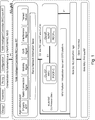
- FIG. 1 shows the 5G-gNB (fifth generation base station) under consideration by the O-RAN alliance and the function for managing it.
- the 5G-gNB includes a RIC (RAN Intelligent Controller), a central unit (CU), a distributed unit (DU) and a radio unit (RU).
- the DU is called O-RAN DU (O-DU) and the RU is called O-RAN RU (O-RU).
- WG4 Working Group 4 of the O-RAN Alliance is considering an open front hall interface between O-DU and O-RU.
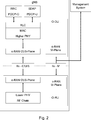
- FIG. 2 shows the C / U-plane and management plane (M-plane) of O-RAN.
- M-plane management plane
- O-RAN in O-RAN, O-DU and O-RU in gNB are connected to each other by C / U-plane and M-plane. There is no special node between O-DU and O-RU.
- the O-RU is also allowed to have an M-plane interface with a network management system (NMS).
- NMS network management system
- an intermediate node is arranged between the O-DU and the O-RU, and the intermediate node can transmit a signal between the O-DU and the O-RU.
- FIG. 3 shows an example in which FHM is arranged in the O-RAN.
- the FHM is arranged between the O-DU and the O-RU.
- the FHM can copy the downlink signal (the signal from the O-DU to the O-RU) and transmit the same downlink signal to a plurality of O-RUs.
- FHM can combine uplink signals (signals from O-RU to O-DU) from a plurality of O-RUs. In such a case, the plurality of O-RUs transmit and receive a common radio signal to form one logic cell.
- FIG. 4 shows an example of an O-RU cascade configuration.
- the O-DU and the plurality of O-RUs are connected in series.
- the Cascaded O-RU copies the downlink signal, transmits the downlink signal to the adjacent O-RU, and also wirelessly transmits the downlink signal to the UE.
- Cascaded O-RU synthesizes an uplink signal from an adjacent O-RU and an uplink signal received wirelessly by itself.
- the plurality of O-RUs transmit and receive a common radio signal to form one logic cell.
- the above-mentioned logical cell may also be referred to as a shared cell.
- the synthesis of uplink signals is not limited to simple synthesis (for example, calculation of sum or average), but selective synthesis (for example, selection of one uplink signal, simple synthesis of a plurality of selected uplink signals). It may be a composite, or a simple composite after weighting a plurality of uplink signals, etc.).
- FIG. 5 shows an example of a schematic configuration of the system 10 according to the first embodiment.
- the system 10 includes a radio access network node (RAN) node 100, an intermediate node 200 and a radio unit (RU) 300.
- RAN radio access network node
- RU radio unit
- the system according to the first embodiment conforms to the technical specifications (TS) of 3GPP (Third Generation Partnership Project). Further, for example, the system according to the first embodiment also complies with the technical specifications (TS) of the O-RAN Alliance.
- TS technical specifications
- the RAN node 100 is an O-DU and the RU 300 is an O-RU.
- the system according to the first embodiment is not limited to these examples.
- the system 10 may include a plurality of intermediate nodes 200 and / or a plurality of RU300s, as will be described later.
- Each node-RAN node 100 communicates with one or more user devices (UEs) via the RU 300. For example, the RAN node 100 transmits a downlink signal to the UE via the RU 300 and receives the uplink signal via the RU 300.
- UEs user devices
- the RAN node 100 communicates with one or more user devices via the plurality of RUs.
- the RAN node 100 is a first RAN node that processes at least one lower layer of the protocol stack of a radio access network (RAN).
- the at least one lower protocol layer includes a wireless link control (RLC) layer, a medium access control (MAC) layer, and a higher physical (High PHY) layer.
- RLC wireless link control
- MAC medium access control
- High PHY higher physical
- the RAN node 100 (the first RAN node) is connected to a second RAN node that processes at least one upper protocol layer in the protocol stack.
- the at least one upper protocol layer includes a packet data convergence protocol (PDCP) layer, a radio resource control (RRC) layer, and a service data conformance protocol (SDAP) layer.
- PDCP packet data convergence protocol
- RRC radio resource control
- SDAP service data conformance protocol
- the RAN node 100 (the first RAN node) is a DU (for example, O-DU), and the second RAN node is a CU (for example, O). -CU).
- a plurality of first RAN nodes (for example, O-DU) may be connected to the second RAN node (for example, O-CU).
- the RAN node 100 also operates as a controller for controlling the configuration of the RU 300.
- the RU 300 is an O-RU
- the RAN node 100 operates as an O-RU controller that controls the configuration of the RU 300.
- the RU300 performs radio frequency (RF) processing.
- RF radio frequency
- the RU 300 also further processes the lower PHY layer.
- the intermediate node 200 transmits a signal between the RAN node 100 and the RU 300.
- the intermediate node 200 may be an FHM or a RU in a cascade configuration (ie, a cascaded RU).
- the intermediate node 200 may be a combination of FHM and RU in a cascade configuration. The specific operation of the intermediate node 200 will be described in detail later.
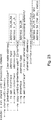
- FIG. 6 shows a first example of M-plane and C / U-plane connections in a first embodiment.
- the system 10 includes six RU300s (RU300A, 300B, 300C, 300D, 300E, 300F) and the intermediate node 200 is an FHM.
- the RAN node 100 establishes a connection for M-plane with each RU 300 and a connection for M-plane with the intermediate node 200.
- these M-plane connections are protocol connections (eg, NETCONF Connection) used for network configuration.
- the RAN node 100 manages the intermediate node 200 and each RU 300 by using the connection for these M-planes.
- the RAN node 100 establishes a connection with the intermediate node 200 for C / U-plane communication in units of logical cells (shared cells).
- a connection between the intermediate node 200 and each RU 300 is also established for C / U-plane communication.
- the intermediate node 200 performs copy processing of the downlink signal (downlink traffic) and synthesis processing of the uplink signal (uplink traffic).
- the RAN node 100 communicates with one or more UEs via six RU300s (RU300A, 300B, 300C, 300D, 300E, 300F).
- the intermediate node 200 transmits a signal between the RAN node 100 and the six RUs 300.
- the RAN node 100 communicates with one or more UEs via the RU 300A, 300B, 300C, and the intermediate node 200 transmits a signal between the RAN node 100 and the RU 300A, 300B, 300C.
- the intermediate node 200 receives (from the RAN node 100) the downlink signal transmitted via the RU 300A, 300B, 300C, copies it, and transmits it to the RU 300A, 300B, 300C.
- the intermediate node 200 synthesizes the uplink signal received via the RU 300A, 300B, and 300C, and transmits the synthesized uplink signal (to the RAN node 100). Since the RUs 300A, 300B, and 300C transmit a common downlink signal and receive a common uplink signal, they form one shared cell.
- the RAN node 100 communicates with one or more UEs via the RU300D, 300E, 300F, and the intermediate node 200 transmits a signal between the RAN node 100 and the RU300D, 300E, 300F.
- the intermediate node 200 receives (from the RAN node 100) the downlink signal transmitted via the RU 300D, 300E, 300F, copies it, and transmits it to the RU 300D, 300E, 300F.
- the intermediate node 200 synthesizes the uplink signal received via the RU 300D, 300E, and 300F, and transmits the synthesized uplink signal (to the RAN node 100). Since the RU300D, 300E, and 300F transmit a common downlink signal and receive a common uplink signal, they form one shared cell.
- the synthesis of the uplink signals may be a simple synthesis (eg, sum or average calculation), or a selective synthesis (eg, selection of one uplink signal, a simple synthesis of multiple selected uplink signals). It may be a composite, or a simple composite after weighting a plurality of uplink signals, etc.). More generally, the synthesis of uplink signals means generating a suitable uplink signal based on a plurality of uplink signals. This also applies to the synthesis process described below.
- the system 10 includes 6 RU300s, but the system 10 may include 2 or more and 5 or less RU200s, or 7 or more RU300s. That is, more generally, the system 10 may include two or more RU300s.
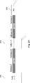
- FIG. 7 shows a second example of the connection of M-plane and C / U-plane in the first embodiment.
- the system 10 includes two intermediate nodes 200 (intermediate nodes 200A, 200B), each of which also operates as a RU, and a RU 300. That is, in the second example, the system 10 has a cascade configuration, and the two intermediate nodes 200 are cascaded RUs (eg, cascaded O-RUs).
- the RAN node 100 establishes a connection for M-plane with each intermediate node 200 and a connection for M-plane with RU300.
- the connection for these M-planes is NETCONF Connection.
- the RAN node 100 manages each intermediate node 200 and RU 300 by using the connection for these M-planes.
- the RAN node 100 establishes a connection with the intermediate node 200 (specifically, the intermediate node 200A) for C / U-plane communication in units of logical cells (shared cells). Further, for C / U-plane communication, a connection between the intermediate node 200A and the intermediate node 200B and a connection between the intermediate node 200B and the RU300 are also established. Each intermediate node 200 performs copy processing of the downlink signal (downlink traffic) and synthesis processing of the uplink signal (uplink traffic).
- the RAN node 100 communicates with one or more UEs via three RUs (intermediate nodes 200A, 200B and RU300).
- the three RUs and the RAN node 100 are connected in series.
- the intermediate node 200A transmits a signal between the RAN node 100 and the intermediate node 200B
- the intermediate node 200B transmits a signal between the intermediate node 200A and the RU300.
- the intermediate node 200A receives the downlink signal transmitted via the three RUs (intermediate nodes 200A, 200B and RU300), copies it, and transmits it to the intermediate node 200B.
- the intermediate node 200B also receives the downlink signal, copies it, and transmits it to the RU 300.
- the intermediate node 200B synthesizes the uplink signal received via the intermediate node 200B (RU) and the RU 300, and transmits the synthesized uplink signal (to the intermediate node 200A).
- the intermediate node 200A is an uplink signal received via the intermediate nodes 200A, 200B (RU) and RU300 (that is, a composite uplink signal received from the intermediate node 200B and an uplink received via the intermediate node 200A. (With the link signal) is synthesized, and the synthesized uplink signal is transmitted (to the RAN node 100).
- the system 10 includes three RUs, but the system 10 may include two RUs (intermediate nodes 200 and RU300) and four or more RUs (three or more intermediate nodes). 200 and RU300) may be included. That is, more generally, the system 10 may include two or more RUs.
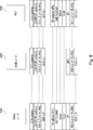
- FIG. 8 shows an example of a protocol stack for M-plane and C / U-plane communication between the RAN node 100 and the RU 300 via the intermediate node 200.
- Ethernet registered trademark
- UDP User Datagram Protocol
- IP Internet Protocol
- the intermediate node 200 performs a copy process of the downlink signal (downlink traffic) and a synthesis process of the uplink signal (uplink traffic) as the C / U-plane process.
- the network configuration protocol NETCONF
- the intermediate node 200 performs IP routing or operates as an ether switch for the M-plane.
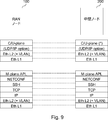
- FIG. 9 shows an example of a protocol stack for M-plane and C / U-plane communication between the RAN node 100 and the intermediate node 200.
- the protocol stack for the C / U-plane is used when the intermediate node 200 also operates as a RU (ie, in a cascade configuration).
- NETCONF is used in M-plane.
- the RAN node 100 is a NETCONF client, and the intermediate nodes 200 and RU300 are NETCONF servers.
- NETCONF is used as a protocol used for network configuration
- the first embodiment is not limited to this example.
- another protocol for example, RESTCONF, etc.
- RESTCONF may be used as the protocol used to configure the network.
- a connection between the RAN node 100 and the intermediate node 200 is established, and a connection between the intermediate node 200 and the RU 300.
- the flow between the RAN node 100 and the intermediate node 200 (upper flow) is configured, and the flow between the intermediate node 200 and the RU 300 (lower flow) is configured.
- the flow may be referred to as a transport flow, interface, link or connection, etc. It should be noted that the flow between adjacent nodes is not configured in this way, but the flow between the RAN node 100 and each node (intermediate node 200 or RU300) is configured as described later as a first modification. May be done.
- the above flow is configured in the M-plane data model at the RU 300 or the intermediate node 200.
- the data model is described in o-ran-processing-element. Yang (especially transport-flow).
- the flow is configured as ETH-INTERFACE (or eth-flow).
- ETH-INTERFACE or eth-flow
- the flow between the RAN node 100 and the intermediate node 200 is configured as the MAC address of the RAN node 100, the MAC address of the intermediate node 200, and the VLAN ID.
- the flow between the intermediate node 200 and the RU 300 is configured as the MAC address of the intermediate node 200, the MAC address of the RU 300, and the VLAN ID.
- the flow may be ALIASMAC-INTERFACE (or aliasmac-flow), and may include a MAC address, an Alias MAC address, and a VLAN ID.
- the flow 50 is configured as ETH-INTERFACE (or eth-flow) and includes a physical MAC address
- each flow 60 is configured as ALIASMAC-INTERFACE (or aliasmac-flow).
- ALIASMAC-INTERFACE or aliasmac-flow
- the Alias MAC address includes the Alias MAC address. Therefore, even if only one physical MAC address exists, a plurality of Alias MAC addresses may exist and a plurality of flows 60 may be configured.
- the flow may be UDPIP-INTERFACE (or UDP-flow) and may include two sets of IP address and UDP port number.
- the flow between the RAN node 100 and the intermediate node 200 may be configured as a set of IP addresses and UDP port numbers of the RAN node 100 and a set of IP addresses and UDP port numbers of the intermediate node 200.
- the flow between the intermediate node 200 and the RU 300 may be configured as a set of IP addresses and UDP port numbers of the intermediate node 200 and a set of IP addresses and UDP port numbers of the RU 300.
- ETH-INTERFACE in these explanations may be replaced with ALIASMAC-INTERFACE or UDPP-INTERFACE.
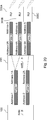
- FIG. 11 shows a first specific example of the system 10 according to the first embodiment.
- the system 10 includes a RAN node 100, an intermediate node 200, and three RU300s (RU300A, 300B, 300C).
- the intermediate node 200 is FHM.
- the RAN node 100 communicates with one or more user devices via three RU300s.
- the intermediate node 200 transmits a signal between the RAN node 100 and the three RUs 300. That is, the intermediate node 200 performs copy processing of the downlink signal (downlink traffic) and synthesis processing of the uplink signal (uplink traffic).
- Flow-1 and Flow-2 are configured between the RAN node 100 and the intermediate node 200.
- Flow-1 includes Address-1 of the RAN node 100 and Address-1A of the intermediate node 200.
- Flow-2 includes Address-2 of RAN node 100 and Address-2A of intermediate node 200.
- Flow-3 includes Address-3A of the intermediate node 200 and Address-3 of the RU300A.
- Flow-4 includes Address-4A of the intermediate node 200 and Address-4 of the RU300B.
- Flow-5 includes Address-5A of the intermediate node 200 and Address-5 of the RU300C.
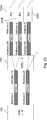
- FIG. 12 shows a second specific example of the system 10 according to the first embodiment.
- the system 10 includes a RAN node 100, an intermediate node 200, and a RU 300.
- the second specific example is an example of a cascade configuration
- the intermediate node 200 is a cascaded RU (for example, a cascaded O-RU) that also operates as a RU.
- the RAN node 100 communicates with one or more user devices via the intermediate node 200 (cascaded RU) and the RU 300.
- the intermediate node 200 transmits a signal between the RAN node 100 and the RU 300. That is, the intermediate node 200 performs copy processing of the downlink signal (downlink traffic) and synthesis processing of the uplink signal (uplink traffic).
- one flow is configured between the RAN node 100 and the intermediate node 200.
- Flow-2 includes Address-2 of RAN node 100 and Address-2A of intermediate node 200.
- one flow is configured between the intermediate node 200 and the RU300.
- Flow-5 includes Address-5A of the intermediate node 200 and Address-5 of the RU300.
- FIG. 13 shows a third specific example of the system 10 according to the first embodiment.
- the system 10 includes a RAN node 100, an intermediate node 200, and three RU300s (RU300A, 300B, 300C), as in the first embodiment. Further, as in the second specific example, the intermediate node 200 also operates as a RU. That is, the third specific example is an example of a combination of the first specific example (FHM) and the second specific example (cascade configuration).
- FHM first specific example
- cascade configuration cascade configuration
- the RAN node 100 communicates with one or more user devices via four RUs (intermediate node 200 and three RUs 300).
- the intermediate node 200 transmits a signal between the RAN node 100 and the three RUs 300. That is, the intermediate node 200 performs copy processing of the downlink signal (downlink traffic) and synthesis processing of the uplink signal (uplink traffic).
- FIG. 14 shows a fourth specific example of the system 10 according to the first embodiment.
- the system 10 includes a RAN node 100, two intermediate nodes 200 (intermediate nodes 200A, 200B), and three RU300s (RU300A, 300B, 300C). That is, the fourth specific example is the one in which one RU is further added to the cascade configuration of the third specific example.
- the RAN node 100 communicates with one or more user devices via five RUs (two intermediate nodes 200 and three RUs 300).
- the intermediate node 200A transmits a signal between the RAN node 100 and the RU 300A, 300B and the intermediate node 200B.
- the intermediate node 200B transmits a signal between the intermediate node 200A and the RU300C. That is, the two intermediate nodes 200 perform copy processing of the downlink signal (downlink traffic) and synthesis processing of the uplink signal (uplink traffic).
- two flows (Flow-1 and Flow-2) are configured between the RAN node 100 and the intermediate node 200A. This point is the same as the first specific example and the third specific example.
- Flow-3 two flows (Flow-3, Flow-4) are configured between the intermediate node 200A and the two RU300s (RU300A, 300B), and the intermediate node 200A and the intermediate node 200B
- One flow (Flow-5) is constructed between them.
- Flow-5 includes an address-5A of the intermediate node 200A and an address-5 of the intermediate node 200B.
- one flow is configured between the intermediate node 200B and the RU300C.
- Flow-6 includes an address-6A of the intermediate node 200B and an address-6 of the RU300C.
- each address here is, for example, a MAC address.
- each address may be an Alias MAC address, or may be a set of an IP address and a UDP port number.
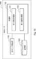
- FIG. 15 shows an example of a schematic configuration of the RAN node 100 according to the first embodiment.
- the RAN node 100 includes a network communication unit 110, a storage unit 120, and a processing unit 130.
- the network communication unit 110 transmits a signal to the intermediate node 200 and receives the signal from the intermediate node 200.
- the network communication unit 110 may transmit a signal to the CU and receive the signal from the CU.
- Storage unit 120 The storage unit 120 temporarily or permanently stores programs (instructions) and parameters for the operation of the RAN node 100, and various data.
- the program includes one or more instructions for the operation of the RAN node 100.
- Processing unit 130 provides various functions of the RAN node 100.
- the processing unit 130 includes a first communication processing unit 131 and a second communication processing unit 133.
- the processing unit 130 may further include other components other than these components. That is, the processing unit 130 may perform operations other than the operations of these components.
- the first communication processing unit 131 performs M-plane processing.
- the second communication processing unit 133 performs C / U-plane processing.
- the processing unit 130 (first communication processing unit 131 and second communication processing unit 133) communicates with another node (for example, intermediate node 200 or RU300) via the network communication unit 110.
- another node for example, intermediate node 200 or RU300
- the network communication unit 110 may be mounted by a network interface (for example, a network adapter or a network interface card) such as Ethernet (registered trademark).
- the storage unit 120 may be mounted by a memory (for example, a non-volatile memory and / or a volatile memory) and / or a hard disk.
- the processing unit 130 may be implemented by one or more processors.
- the first communication processing unit 131 and the second communication processing unit 133 may be implemented by the same processor, or may be separately implemented by different processors.
- the memory (storage unit 120) may be contained in the one or more processors, or may be outside the one or more processors.
- the RAN node 100 may include a memory for storing a program (instruction) and one or more processors capable of executing the program (instruction).
- the one or more processors may execute the above program to perform the operation of the processing unit 130 (the operation of the first communication processing unit 131 and the second communication processing unit 133).
- the program may be a program for causing the processor to execute the operation of the processing unit 130 (the operation of the first communication processing unit 131 and the second communication processing unit 133).
- the RAN node 100 may be virtualized. That is, the RAN node 100 may be implemented as a virtual machine. In this case, the RAN node 100 (virtual machine) may operate as a virtual machine on a physical machine (hardware) including a processor, memory, and the like and a hypervisor.
- a virtual machine may operate as a virtual machine on a physical machine (hardware) including a processor, memory, and the like and a hypervisor.
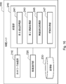
- FIG. 16 shows an example of a schematic configuration of the intermediate node 200 according to the first embodiment.
- the intermediate node 200 includes a network communication unit 210, a wireless communication unit 220, a storage unit 230, and a processing unit 240.
- the network communication unit 210 transmits a signal to the RAN node 100, RU 300 or another intermediate node 200, and receives a signal from the RAN node 100, RU 300 or another intermediate node 200.
- the wireless communication unit 220 performs radio frequency (RF) processing and transmits / receives signals wirelessly. For example, the wireless communication unit 220 receives the signal from the UE and transmits the signal to the UE.
- RF radio frequency
- Storage unit 230 The storage unit 230 temporarily or permanently stores programs (instructions) and parameters for the operation of the intermediate node 200, as well as various data.
- the program includes one or more instructions for the operation of the intermediate node 200.
- the processing unit 240 provides various functions of the intermediate node 200.
- the processing unit 240 includes a first communication processing unit 241 and a second communication processing unit 243, a wireless communication processing unit 245, and an information acquisition unit 247.
- the processing unit 240 may further include other components other than these components. That is, the processing unit 240 may perform operations other than the operations of these components.
- the first communication processing unit 241 performs M-plane processing.
- the second communication processing unit 243 performs C / U-plane processing.
- the wireless communication processing unit 245 processes, for example, the lower physical (Low PHY) layer.
- the information acquisition unit 247 acquires management information as described later.
- the processing unit 240 (first communication processing unit 241 and second communication processing unit 243) communicates with another node (for example, RAN node 100, RU300 or another intermediate node 200) via the network communication unit 210. ..
- the processing unit 240 (wireless communication processing unit 245) communicates with the UE via the wireless communication unit 220.
- the network communication unit 210 may be mounted by a network interface (for example, a network adapter or a network interface card) such as Ethernet (registered trademark).
- the wireless communication unit 220 may be mounted by an antenna, an RF circuit, or the like, and the antenna may be a directional antenna.
- the storage unit 230 may be mounted by a memory (for example, a non-volatile memory and / or a volatile memory) and / or a hard disk.
- the processing unit 240 may be implemented by one or more processors.
- the first communication processing unit 241 and the second communication processing unit 243, the wireless communication processing unit 245, and the information acquisition unit 247 may be implemented by the same processor or may be separately implemented by different processors.
- the memory (storage unit 230) may be contained in the one or more processors, or may be outside the one or more processors.
- the intermediate node 200 may include a memory for storing a program (instruction) and one or more processors capable of executing the program (instruction).
- the one or more processors execute the above program to perform operations of the processing unit 240 (operations of the first communication processing unit 241 and the second communication processing unit 243, the wireless communication processing unit 245, and the information acquisition unit 247).
- the above program may be a program for causing the processor to execute the operation of the processing unit 240 (the operation of the first communication processing unit 241 and the second communication processing unit 243, the wireless communication processing unit 245 and the information acquisition unit 247). ..
- the intermediate node 200 includes the wireless communication unit 220 and the wireless communication processing unit 245
- the intermediate node 200 does not operate as a RU
- the intermediate node 200 has the wireless communication unit 220 and the wireless communication processing unit 245. It is not necessary to have.
- FIG. 17 shows an example of a schematic configuration of the RU 300 according to the first embodiment.
- the RU 300 includes a network communication unit 310, a wireless communication unit 320, a storage unit 330, and a processing unit 340.
- Network communication unit 310 The network communication unit 310 transmits a signal to the intermediate node 200 and receives the signal from the intermediate node 200.
- the wireless communication unit 320 performs radio frequency (RF) processing and transmits / receives signals wirelessly. For example, the wireless communication unit 320 receives the signal from the UE and transmits the signal to the UE.
- RF radio frequency
- Storage unit 330 The storage unit 330 temporarily or permanently stores programs (instructions) and parameters for the operation of the RU 300, as well as various data.
- the program includes one or more instructions for the operation of the RU300.
- the processing unit 340 provides various functions of the RU 300.
- the processing unit 340 includes a first communication processing unit 341, a second communication processing unit 343, a wireless communication processing unit 345, and an information acquisition unit 347.
- the processing unit 340 may further include other components other than these components. That is, the processing unit 340 may perform operations other than the operations of these components.
- the first communication processing unit 341 processes the M-plane.
- the second communication processing unit 343 performs C / U-plane processing.
- the wireless communication processing unit 345 processes, for example, the lower physical (Low PHY) layer.
- the information acquisition unit 347 acquires management information as described later.
- the processing unit 340 (first communication processing unit 341 and second communication processing unit 343) communicates with another node (for example, RAN node 100 or intermediate node 200) via the network communication unit 310.
- the processing unit 340 (wireless communication processing unit 345) communicates with the UE via the wireless communication unit 320.
- the network communication unit 310 may be mounted by a network interface such as Ethernet (registered trademark) (for example, a network adapter or a network interface card).
- the wireless communication unit 320 may be mounted by an antenna, an RF circuit, or the like, and the antenna may be a directional antenna.
- the storage unit 330 may be mounted by a memory (for example, a non-volatile memory and / or a volatile memory) and / or a hard disk.
- the processing unit 340 may be implemented by one or more processors.
- the first communication processing unit 341, the second communication processing unit 343, the wireless communication processing unit 345, and the information acquisition unit 347 may be implemented by the same processor, or may be separately implemented by different processors.
- the memory (storage unit 330) may be contained in the one or more processors, or may be outside the one or more processors.
- the RU 300 may include a memory for storing a program (instruction) and one or more processors capable of executing the program (instruction).
- the one or more processors execute the above program to perform operations of the processing unit 340 (operations of the first communication processing unit 341, the second communication processing unit 343, the wireless communication processing unit 345, and the information acquisition unit 347).
- the above program may be a program for causing the processor to execute the operation of the processing unit 340 (the operation of the first communication processing unit 341, the second communication processing unit 343, the wireless communication processing unit 345, and the information acquisition unit 347). ..
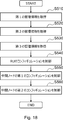
- FIG. 18 is a flowchart for explaining an example of a schematic flow of processing of the RAN node 100 according to the first embodiment. Briefly, first, the RAN node 100 acquires the first management information, the second management information, and the third management information (S510, S520, S530). After that, the RAN node 100 controls the configuration of the RU 300 (S540) and also controls the configuration of the intermediate node 200 (S550, S560).
- Step 510 Acquisition of the first management information
- the RU300 (information acquisition unit 347) indicates the address of the RU300 used by the RU300 to connect to the intermediate node 200 for C / U-plane communication. Get the management information of. Then, the RU 300 (first communication processing unit 341) transmits the first management information to the RAN node 100.
- the RAN node 100 (first communication processing unit 131) receives the first management information from the RU 300. In this way, the RAN node 100 acquires the first management information indicating the address of the RU 300.
- the above address of RU300 is the MAC address of RU300.
- the above address of the RU 300 may be the Alias MAC address of the RU 300, or the IP address and UDP port number of the RU 300.
- the RU 300A transmits the first management information indicating the address of the RU 300A to the RAN node 100
- the RU 300B is the first management information indicating the address of the RU 300B.
- the RU300C transmits the first management information indicating the address-5 of the RU300C to the RAN node 100.
- the RAN node 100 receives the first management information from each of the RUs 300A, 300B, and 300C. In this way, the RAN node 100 acquires the first management information indicating the address-3, the address-4, and the address-5, respectively.
- the RU 300A transmits the first management information indicating the address of the RU 300A to the RAN node 100
- the RU 300B is the first management information indicating the address of the RU 300B.
- the RU300C transmits the first management information indicating the address-6 of the RU300C to the RAN node 100.
- the RAN node 100 receives the first management information from each of the RUs 300A, 300B, and 300C. In this way, the RAN node 100 acquires the first management information indicating the address-3, the address-4, and the address-6, respectively.
- the protocol used to configure the network for transmitting and receiving the first management information is used by the RAN node 100 (client of the protocol) and the RU300 (server of the protocol).
- the protocol is NETCONF
- the client is a NETCONF client
- the server is a NETCONF server.
- the above protocol may be another protocol (for example, RESTCONF, etc.) instead of NETCONF.
- Step 520 Acquisition of the second management information
- the intermediate node 200 is located on the RAN node 100 (or the RAN node 100 side) for C / U-plane communication.
- the second management information indicating the address of the intermediate node 200 used for the connection with the intermediate node 200) is acquired.
- the intermediate node 200 (first communication processing unit 241) transmits the second management information to the RAN node 100.
- the RAN node 100 (first communication processing unit 131) receives the second management information from the intermediate node 200. In this way, the RAN node 100 acquires the second management information indicating the address of the intermediate node 200.
- the above address of the intermediate node 200 is the MAC address of the intermediate node 200.
- the address of the intermediate node 200 may be the Alias MAC address of the intermediate node 200, or the IP address and UDP port number of the intermediate node 200.
- the intermediate node 200 acquires the second management information indicating the address-1A and the address-2A of the intermediate node 200, and transfers the second management information to the RAN node 100. Send.
- the RAN node 100 receives the second management information. In this way, the RAN node 100 acquires the second management information indicating the address-1A and the address-2A.
- the intermediate node 200A acquires the second management information indicating Address-1A and Address-2A of the intermediate node 200A, and transfers the second management information to the RAN node 100.
- the intermediate node 200B acquires the second management information indicating the address-5 of the intermediate node 200B, and transmits the second management information to the RAN node 100.
- the RAN node 100 receives the second management information from each of the intermediate node 200A and the intermediate node 200B. In this way, the RAN node 100 acquires the second management information indicating the address-1A and the address-2A and the second management information indicating the address-5.
- the protocol used to configure the network for transmitting and receiving the second management information is used by the RAN node 100 (the protocol client) and the intermediate node 200 (the protocol server).
- the protocol is NETCONF
- the client is a NETCONF client
- the server is a NETCONF server.
- the above protocol may be another protocol (for example, RESTCONF, etc.) instead of NETCONF.
- Step 530 Acquisition of the third management information
- the intermediate node 200 (information acquisition unit 247) is the address of the intermediate node 200 used by the intermediate node 200 to connect to the RU 300 for C / U-plane communication. And the address of the RU300 used by the RU300 to connect to the intermediate node 200 for the communication of the C / U-plane, and the third management information indicating the correspondence relationship is acquired. Then, the intermediate node 200 (first communication processing unit 241) transmits the third management information to the RAN node 100.
- the third management information includes the address of the intermediate node 200 and the address of the RU 300.
- the address of the intermediate node 200 is the MAC address of the intermediate node 200
- the address of the RU 300 is the MAC address of the RU 300.
- the address of the intermediate node 200 may be the Alias MAC address of the intermediate node 200
- the address of the RU 300 may be the Alias MAC address of the RU 300.
- the address of the intermediate node 200 may be the IP address and UDP port number of the intermediate node 200
- the address of the RU 300 may be the IP address and UDP port number of the RU 300.
- the intermediate node 200 has a correspondence relationship between the address-3A of the intermediate node 200 and the address-3 of the RU300A, and the address-4A of the intermediate node 200 and the address of the RU300B.
- the intermediate node 200 transmits the third management information to the RAN node 100.
- the RAN node 100 receives the third management information. In this way, the RAN node 100 acquires the third management information indicating each correspondence.
- the intermediate node 200A has a correspondence relationship between the address-3A of the intermediate node 200A and the address-3 of the RU300A, and the address-4A of the intermediate node 200A and the address-4 of the RU300B.
- the intermediate node 200A transmits the third management information to the RAN node 100.
- the intermediate node 200B acquires the correspondence between the address-6A of the intermediate node 200B and the address-6 of the RU300C.
- the intermediate node 200B transmits the third management information to the RAN node 100.
- the RAN node 100 receives the third management information from each of the intermediate nodes 200A and 200B. In this way, the RAN node 100 acquires the third management information indicating each correspondence.
- the above address is a MAC address
- the above second management information is adjacent interface information acquired from physical port connection information.
- the intermediate node 200 (information acquisition unit 247) acquires the adjacent interface information by Loopback Request and Response of Ethernet OAM (Operations, Addinition, Mainence).
- the above address may be an IP address and a UDP port number.
- the intermediate node 200 uses the above second management information as a DHCP (Dynamic Host Configuration Protocol) process and. / Or it may be acquired by ARP (Address Resolution Protocol).
- DHCP Dynamic Host Configuration Protocol
- ARP Address Resolution Protocol
- the interface for the RU300 of the intermediate node 200 may be configured as an IETF-interface, IETF-ip.
- IETF-ip an IETF-interface
- the intermediate node 200 (information acquisition unit 247) may acquire such information as the third management information.
- the intermediate node 200 transmits the third management information to the RAN node 100 using the protocol used for network configuration, and the RAN node 100 (first communication processing unit 241). 131) receives the third management information from the intermediate node 200 using the protocol.
- the intermediate node 200 is a server of the above protocol
- the RAN node 100 (first communication processing unit 131) is a client of the above protocol.
- the protocol is NETCONF
- the client is a NETCONF client
- the server is a NETCONF server.
- the above protocol may be another protocol (for example, RESTCONF, etc.) instead of NETCONF.
- Step 540 Control of RU300 configuration
- the RAN node 100 (first communication processing unit 131) controls the configuration of the RU300 based on the first management information and the second management information.
- the above configuration of the RU300 is a flow configuration between the intermediate node 200 and the RU300.
- the configuration of the flow corresponds to the address of the RU 300 corresponding to the flow (the address of the RU 300 used by the RU 300 to connect to the intermediate node 200 for C / U-plane communication) and the flow.
- the address of the intermediate node 200 (the address of the intermediate node 200 used by the intermediate node 200 to connect to the RU 300 for C / U-plane communication) is included.
- the configuration of the flow further includes a virtual local area network (VLAN) ID.
- VLAN virtual local area network
- the RAN node 100 determines the above configuration of the RU 300, and transmits the configuration information indicating the above configuration of the RU 300 to the RU 300.
- the RU300 receives the configuration information from the RAN node 100 and sets the configuration in the RU300.
- the protocol used to configure the network is used by the RAN node 100 (client of the protocol) and RU300 (server of the protocol).
- the protocol is NETCONF
- the client is a NETCONF client
- the server is a NETCONF server.
- the above protocol may be another protocol (for example, RESTCONF, etc.) instead of NETCONF.
- the RAN node 100 determines the configuration of Flow-3 (configuration of RU300A) including Address-3A, Address-3 and VLAN ID. Then, the RAN node 100 transmits the configuration information indicating the configuration to the RU 300A. Then, the RU300A sets the above configuration to the RU300A. As a result, Flow-3 is constructed.
- the RAN node 100 determines the configuration of Flow-4 (configuration of RU300B) including Address-4A, Address-4 and VLAN ID. Then, the RAN node 100 transmits the configuration information indicating the configuration to the RU 300B. Then, the RU300B sets the above configuration to the RU300B. As a result, Flow-4 is constructed.
- the RAN node 100 determines the configuration of Flow-5 (configuration of RU300C) including Address-5A, Address-5 and VLAN ID. Then, the RAN node 100 transmits the configuration information indicating the configuration to the RU300C. Then, the RU300C sets the above configuration to the RU300C. As a result, Flow-5 is configured.
- Step 550 Control of the first configuration of the intermediate node 200
- the RAN node 100 (first communication processing unit 131) performs the first configuration of the intermediate node 200 based on the second management information. Control.
- the first configuration of the intermediate node 200 is the configuration of the flow between the RAN node 100 (or another intermediate node 200 on the RAN node 100 side) and the intermediate node 200.
- the RAN node 100 uses the RAN node 100 (or another intermediate node 200) to connect to the intermediate node 200 for C / U-plane communication.
- the configuration of the flow further includes a virtual local area network (VLAN) ID.
- VLAN virtual local area network
- the RAN node 100 determines the first configuration of the intermediate node 200, and provides configuration information indicating the first configuration of the intermediate node 200 to the intermediate node 200. Send to.
- the intermediate node 200 receives the configuration information from the RAN node 100 and sets the configuration to the intermediate node 200.
- the protocol used to configure the network is used by the RAN node 100 (client of the protocol) and the intermediate node 200 (server of the protocol).
- the protocol is NETCONF
- the client is a NETCONF client
- the server is a NETCONF server.
- the above protocol may be another protocol (for example, RESTCONF, etc.) instead of NETCONF.
- the RAN node 100 has a configuration of Flow-1 including Address-1, Address-1A and a VLAN ID (configuration of the intermediate node 200) and an Address-. 2. Determine the configuration of Flow-2 (configuration of intermediate node 200) including Address-2A and VLAN ID. Then, the RAN node 100 transmits the configuration information indicating the configuration to the intermediate node 200. Then, the intermediate node 200 sets the above configuration to the intermediate node 200. As a result, Flow-1 and Flow-2 are constructed.
- Step 560 Setting the Second Configuration of the Intermediate Node 200
- the RAN node 100 (first communication processing unit 131) bases the intermediate node 200 based on the second management information and the third management information. Controls the second configuration of.
- the above-mentioned second configuration of the intermediate node 200 is an intermediate flow between the RAN node 100 (or another intermediate node 200 on the RAN node 100 side) and the intermediate node 200. Includes a correspondence configuration with the lower flow between the node 200 and the RU 300 (or another intermediate node 200 that also acts as a RU).
- the address of the RAN node (or another intermediate node 200) or the intermediate node 200 corresponding to the upper flow and the intermediate node 200 or RU300 (or RU) corresponding to the lower flow also includes the addresses of other intermediate nodes 200) that also operate.
- the configuration of the correspondence may include the identification information of the upper flow and the identification information of the lower flow.
- the second configuration of the intermediate node 200 is the RAN node 100 (or the other intermediate node 200) and the intermediate node 200. Includes a correspondence configuration of each upper flow between and one or more lower flows between the corresponding one or more RUs of the plurality of RUs and the intermediate node 200.
- the corresponding one or more RUs form one shared cell.
- the second configuration of the intermediate node 200 is the RAN node 100 (or the other intermediate node 200).
- the wireless communication corresponds to "radio" described later.
- the RAN node 100 determines the second configuration of the intermediate node 200, and provides configuration information indicating the second configuration of the intermediate node 200 to the intermediate node 200. Send to.
- the intermediate node 200 receives the configuration information from the RAN node 100 and sets the configuration to the intermediate node 200.
- the protocol used to configure the network is used by the RAN node 100 (client of the protocol) and the intermediate node 200 (server of the protocol).
- the RAN node 100 is Flow-1 (upper row). Determine the configuration of the correspondence between Flow) and Flow-3 and Flow-4 (lower flow). Further, the RAN node 100 determines the configuration of the correspondence between Flow-2 (upper flow) and Flow-5 (lower flow).
- the correspondence configuration is, for example, one of the following first to fifth examples.
- First example Address-1A-Address-3, Address-4 Address-2A-Address-5 (Second example) Address-1-Address-3A, Address-4A Address-2 - Address-5A (Third example) Address-1A-Address-3A, Address-4A Address-2A-Address-5A (Fourth example) Address-1-Address-3, Address-4 Address-2-Address-5 (Fifth example) Flow-1-Flow-3, Flow-4 Flow-2-Flow-5
- FIG. 21 shows an example (YANG) of the second configuration (correspondence-related configuration) of the intermediate node 200.
- YANG YANG
- Such a configuration is set on the intermediate node 200.
- This example corresponds to the third example described above.
- the RAN node 100 is referred to as Flow-1 (upper flow). Determine the configuration of the correspondence between Flow-3 and Flow-4 (lower flow). Further, the RAN node 100 determines the configuration of the correspondence between Flow-2 (upper flow) and Flow-5 (lower flow) and radio. That is, the only difference between the third specific example of FIG. 22 and the first specific example of FIG. 20 is this "radio". This "radio" means wireless communication by the intermediate node 200 itself, which is also a RU.
- the correspondence configuration is, for example, one of the following first to fifth examples.
- First example Address-1A-Address-3, Address-4 Address-2A-Address-5, radio (Second example) Address-1-Address-3A, Address-4A Address-2-Address-5A, radio (Third example) Address-1A-Address-3A, Address-4A Address-2A-Address-5A, radio (Fourth example) Address-1-Address-3, Address-4 Address-2-Address-5, radio (Fifth example) Flow-1-Flow-3, Flow-4 Flow-2-Flow-5, radio
- FIG. 23 shows an example (YANG) of the second configuration (correspondence-related configuration) of the intermediate node 200.
- YANG YANG
- Such a configuration is set on the intermediate node 200.
- This example corresponds to the third example described above.
- the address-type differs depending on the transport-flow set in each RU.
- uplane-conf A wireless module such as yang is specified.
- the terminal RU (RU300A, 300B, 300C) does not have an o-ran-shard-cell-processing-element yang module, or does not have an interface-conception list, and has a copy-combine-interface-pair. Received address and radio are specified.
- the operation of the fourth specific example of FIG. 14 is the third specific example of FIG. 23, except that the configuration of the correspondence between Flow-5 and Flow-6 and radio is determined and set. It is the same as the above-mentioned operation for the example.
- the RAN node 100 is referred to as Flow-2 (upper flow). Determine the configuration of the correspondence with Flow-5 (lower flow) and radio.
- This "radio" means wireless communication by the intermediate node 200 itself, which is also a RU.
- the correspondence configuration is, for example, one of the following first to fifth examples.
- First example Address-2A-Address-5, radio (Second example) Address-2-Address-5A, radio (Third example) Address-2A-Address-5A, radio (Fourth example) Address-2-Address-5, radio (Fifth example) Flow-2-Flow-5, radio
- FIG. 25 shows an example (YANG) of the second configuration (correspondence relationship configuration) of the intermediate node 200.
- YANG YANG
- Such a configuration is set on the intermediate node 200.
- This example corresponds to the third example described above.
- the address-type differs depending on the transport-flow set in each RU.
- uplane-conf. Specify a wireless module such as yang.
- the terminal RU (RU300) does not have an o-ran-shared-cell-processing-element yang module, or does not have an interface-connection list, and is received by copy-combine-interfaces-pair. Is specified.
- a flow between adjacent nodes is configured.
- the flow between the RAN node 100 and the intermediate node 200 is configured as the upper flow
- the flow between the intermediate node 200 and the RU 300 is configured as the lower flow.
- a flow between the RAN node 100 and each node is configured.
- the flow between the RAN node 100 and the intermediate node 200 is configured as the upper flow
- the flow between the intermediate node 200 and the RU 300 is not configured as the lower flow
- the flow between the RAN node 100 and the RU 300 is It is configured as a lower flow.
- FIG. 26 shows an example of the flow of the first modification in the first specific example of the system 10 according to the first embodiment.
- Flow-1 and Flow-2 are configured as the upper flow between the RAN node 100 and the intermediate node 200.
- Flow-1 includes Address-1 of the RAN node 100 and Address-1A of the intermediate node 200.
- Flow-2 includes Address-2 of RAN node 100 and Address-2A of intermediate node 200. This point is the same as the above-mentioned example with reference to FIG.
- Flow-3 includes Address-1 of RAN node 100 and Address-3 of RU300A.
- Flow-4 includes Address-1 of RAN node 100 and Address-4 of RU300B.
- Flow-5 includes Address-2 of RAN node 100 and Address-5 of RU300C.
- FIG. 27 shows an example of the flow of the first modification in the second specific example of the system 10 according to the first embodiment.
- Flow-2 One flow (Flow-2) is configured between the RAN node 100 and the intermediate node 200.
- Flow-2 includes Address-2 of RAN node 100 and Address-2A of intermediate node 200. This point is the same as the above-mentioned example with reference to FIG.
- one flow (Flow-5) is configured between the RAN node 100 and the RU300.
- Flow-5 includes Address-2 of RAN node 100 and Address-5 of RU300.
- FIG. 28 shows an example of the flow of the first modification in the third specific example of the system 10 according to the first embodiment.
- the flow in the third specific example is the same as the flow in the first specific example of FIG. Therefore, duplicate description will be omitted.
- FIG. 29 shows an example of the flow of the first modification in the fourth specific example of the system 10 according to the first embodiment.
- Two flows (Flow-1 and Flow-2) are configured between the RAN node 100 and the intermediate node 200A. This point is the same as the above-mentioned example with reference to FIG.
- one flow (Flow-5) is configured between the RAN node 100 and the intermediate node 200B.
- Flow-5 includes Address-2 of RAN node 100 and Address-5 of intermediate node 200B.
- Flow-3 includes Address-1 of RAN node 100 and Address-3 of RU300A
- Flow-4 contains Address-1 of RAN node 100 and Address-4 of RU300B
- Flow-6 contains RAN. Includes Address-2 of node 100 and Address-6 of RU300C.
- Step 540 Controlling the configuration of the RU 300
- the RAN node 100 (first communication processing unit 131) configures the RU 300 based on the first management information and the second management information. Control.
- the configuration of the RU 300 is the configuration of the flow between the RAN node 100 and the RU 300.
- the above configuration of the above flow corresponds to the address of the RU 300 corresponding to the above flow (the address of the RU 300 used by the RU 300 to connect to the intermediate node 200 for C / U-plane communication) and the above flow.
- the address of the RAN node 100 to be used (the address of the RAN node 100 used by the RAN node 100 to connect to the intermediate node 200 for C / U-plane communication) is included.
- the above configuration of the above flow further includes a VLAN ID.
- the RAN node 100 determines the configuration of Flow-3 (configuration of RU300A) including Address-1, Address-3 and VLAN ID. Then, the RAN node 100 transmits the configuration information indicating the configuration to the RU 300A. Then, the RU300A sets the above configuration to the RU300A. As a result, Flow-3 is constructed.
- the RAN node 100 determines the configuration of Flow-4 (configuration of RU300B) including Address-1, Address-4 and VLAN ID. Then, the RAN node 100 transmits the configuration information indicating the configuration to the RU 300B. Then, the RU300B sets the above configuration to the RU300B. As a result, Flow-4 is constructed.
- the RAN node 100 determines the configuration of Flow-5 (configuration of RU300C) including Address-2, Address-5, and VLAN ID. Then, the RAN node 100 transmits the configuration information indicating the configuration to the RU300C. Then, the RU300C sets the above configuration to the RU300C. As a result, Flow-5 is configured.
- Step 550 Control of the first configuration of the intermediate node 200
- the RAN node 100 (first communication processing unit 131) is the first of the intermediate nodes 200 based on the second management information. Control the configuration.
- the first configuration of the intermediate node 200 is the configuration of the flow between the RAN node 100 and the intermediate node 200.
- the configuration of the flow is the address of the RAN node 100 corresponding to the flow (the address of the RAN node 100 used by the RAN node 100 to connect to the intermediate node 200 for C / U-plane communication). And the address of the intermediate node 200 corresponding to the above flow (the address of the intermediate node 200 used by the intermediate node 200 to connect to the RAN node 100 for C / U-plane communication). Further, the above configuration of the above flow further includes a VLAN ID.
- the RAN node 100 has a configuration of Flow-1 including Address-1, Address-1A and a VLAN ID (configuration of the intermediate node 200) and an Address. -2, Address-2A and the configuration of Flow-2 including the VLAN ID (configuration of the intermediate node 200) are determined. Then, the RAN node 100 transmits the configuration information indicating the configuration to the intermediate node 200. Then, the intermediate node 200 sets the above configuration to the intermediate node 200. As a result, Flow-1 and Flow-2 are constructed.
- the RAN node 100 further determines the configuration of Flow-5 including the Address-2, Address-5, and VLAN ID (configuration of the intermediate node 200B). Then, the RAN node 100 transmits the configuration information indicating the configuration to the intermediate node 200B. Then, the intermediate node 200B sets the above configuration to the intermediate node 200B. As a result, Flow-5 is configured.
- Step 560 Setting the Second Configuration of the Intermediate Node 200
- the RAN node 100 (first communication processing unit 131) is based on the second management information and the third management information. Controls the second configuration of intermediate node 200.
- the second configuration of the intermediate node 200 is the upper flow between the RAN node 100 and the intermediate node 200, and the RAN node 100 and the RU300 ( Alternatively, it includes a configuration of a correspondence relationship with a lower flow with another intermediate node 200) that also operates as a RU.
- the configuration of the correspondence is the address of the RAN node or the intermediate node 200 corresponding to the upper flow and the intermediate node 200 or the RU 300 (or another intermediate node 200 that also operates as the RU) corresponding to the lower flow. ) And the address.
- the configuration of the correspondence relationship includes the address of the intermediate node 200 corresponding to the lower flow
- the address of the intermediate node 200 corresponding to the lower flow is two of the intermediate nodes 200 in the route of the lower flow.
- the address on the RU300 side that is, the address of the intermediate node 200 used by the intermediate node 200 for connection with the RU 300 (or another intermediate node 200 operating as the RU)).
- the configuration of the correspondence relationship may include the identification information of the upper flow and the identification information of the lower flow.
- the second configuration of the intermediate node 200 includes each upper flow between the RAN node 100 and the intermediate node 200. Includes a correspondence configuration with one or more lower flows between one or more corresponding RUs of the plurality of RUs and the RAN node 100.
- the corresponding one or more RUs form one shared cell.
- the second configuration of the intermediate node 200 is the upper stage between the RAN node 100 and the intermediate node 200.
- the configuration of the correspondence between the flow and the wireless communication by the intermediate node 200 (RU) is included.
- the wireless communication corresponds to "radio".
- the intermediate node 200 transmits the third management information to the RAN node 100.
- the RU 300 (information acquisition unit 347) acquires the third management information, and the RU 300 (first communication processing unit 341) sends the RAN node 100 to the above.
- the third management information is transmitted.
- the RU300A acquires a third management showing the correspondence between the address of the intermediate node 200 and the address-3 of the RU300A, and the third management is the RAN node.
- Send to 100 The RU300B acquires a third management indicating the correspondence between the address-4A of the intermediate node 200 and the address-4 of the RU300B, and transmits the third management to the RAN node 100.
- the RU300C acquires a third management indicating the correspondence between the address-5A of the intermediate node 200 and the address-5 of the RU300B, and transmits the third management to the RAN node 100.
- the RAN node 100 receives the third management information from each of the RUs 300A, 300B, and 300C. In this way, the RAN node 100 acquires the third management information indicating each correspondence.
- the interface for the intermediate node 200 of the RU 300 may be configured as an IETF-interface, an IETF-ip.
- the RU 300 (information acquisition unit 347) may acquire such information as the third management information.
- the second modification may be combined with the first modification. That is, in the second modification, the flow may be configured as in the first modification.
- the RAN node 100 operates as a controller for controlling the configuration of the RU300 (and the intermediate node 200).
- the network management system operates as the controller. Therefore, in the third modification, the operation of the RAN node 100 (operation of the M-plane) in the above-described example of the first embodiment is performed by the network management system.
- the third modification may be combined with the second modification. That is, the RU 300 may transmit the above-mentioned third management information to the network management system.
- the third modification may be combined with the first modification. That is, in the third modification, the flow may be configured as in the first modification.
- the intermediate node 200 acquires capability information indicating the capabilities of the intermediate node 200 for C / U-plane and / or M-plane, and controls the capability information (information acquisition unit 247 and first communication processing unit 241). It may be transmitted to the RAN node 100 or the network management system).
- the above-mentioned capability information may include the following information.
- -Information indicating whether the intermediate node 200 can perform wireless transmission / reception for example, RF processing and processing of the lower physical (Low PHY) layer
- -Information indicating whether the intermediate node 200 can perform copy processing / synthesis processing Information indicating whether the intermediate node 200 can perform copy processing / synthesis processing
- -Information indicating conditions under which copy processing / compositing processing of the intermediate node 200 can be performed for example, the capability of the RU connected to the intermediate node 200 (for example, an antenna)
- the number, transmission output, transmission frequency and / or number of transmission carriers, beamforming function, number of packets that can be transmitted simultaneously, and some or all of the RU capabilities specified by M-plane) are the same. ,etc)
- the controller (RAN node 100 or network management system) (first communication processing unit 131) configures the intermediate node 200 (for example, the first configuration and / or the second configuration). Configuration) may be controlled.
- Second embodiment >> Subsequently, a second embodiment of the present invention will be described with reference to FIGS. 31 to 33.
- the first embodiment described above is a specific embodiment, but the second embodiment is a more generalized embodiment.
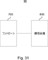
- FIG. 31 shows an example of a schematic configuration of the system 90 according to the second embodiment.
- the system 90 includes a controller 700 and a communication device 800.
- the controller 700 controls the configuration of the intermediate node and / or RU.
- the communication device 800 transmits the management information to the controller 700.
- the controller 700 is the RAN node 100 of the first embodiment
- the communication device 800 is the intermediate node 200 of the first embodiment.
- the controller 700 may be a network management system (NMS) instead of the RAN node 100.
- the communication device 800 may be the RU 300 of the first embodiment instead of the intermediate node 200.
- the second embodiment is not limited to these examples.
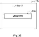
- FIG. 32 shows an example of a schematic configuration of the controller 700 according to the second embodiment.
- the controller 700 includes a communication processing unit 710.
- the communication processing unit 710 processes the M-plane.
- the communication processing unit 710 may be implemented by one or more processors (and memory).
- the controller 700 may include a memory for storing a program (instruction) and one or more processors capable of executing the program (instruction).
- the one or more processors may execute the above program to operate the communication processing unit 710.
- the above program may be a program for causing the processor to execute the operation of the communication processing unit 710.
- controller 700 may be virtualized. That is, the controller 700 may be implemented as a virtual machine.
- the controller 700 (virtual machine) may operate as a virtual machine on a physical machine (hardware) including a processor, memory, and the like, and a hypervisor.
- FIG. 33 shows an example of a schematic configuration of the communication device 800 according to the second embodiment.
- the communication device 800 includes an information acquisition unit 810 and a communication processing unit 820.
- the information acquisition unit 810 acquires management information.
- the communication processing unit 820 processes the M-plane.
- the information acquisition unit 810 and the communication processing unit 820 may be implemented by one or more processors (and memories).
- the information acquisition unit 810 and the communication processing unit 820 may be implemented by the same processor, or may be separately implemented by different processors.
- the communication device 800 may include a memory for storing a program (instruction) and one or more processors capable of executing the program (instruction).
- the one or more processors may execute the above program to operate the information acquisition unit 810 and the communication processing unit 820.
- the above program may be a program for causing the processor to execute the operations of the information acquisition unit 810 and the communication processing unit 820.
- the intermediate node that transmits a signal between the RAN node that communicates with one or more UEs via the RU that performs radio frequency processing and the RU is a C / U-plane communication.
- the correspondence between the address of the intermediate node used for the connection with the RU for the above and the address of the RU used for the connection with the intermediate node for the communication of the C / U-plane by the RU. Acquire the management information to be shown.
- the communication device 800 (communication processing unit 820) transmits the management information to the controller 700 that controls the configuration of the wireless unit.
- the controller 700 receives the management information and controls the configuration of the RU or the intermediate node based on the management information.
- the communication device 800 (information acquisition unit 810 and communication processing unit 820) operates in the same manner as the intermediate node 200 (information acquisition unit 247 and first communication processing unit 241) of the first embodiment.
- the controller 700 (communication processing unit 710) operates in the same manner as the RAN node 100 (first communication processing unit 131) of the first embodiment.
- the second embodiment is not limited to this example.
- the steps in the processing described in the present specification do not necessarily have to be executed in chronological order in the order described in the flowchart.
- the steps in the process may be executed in an order different from the order described in the flowchart, or may be executed in parallel.
- a part of the steps in the process may be deleted, and additional steps may be added to the process.
- a method including each process of the RAN node, the intermediate node, the RU, the controller and the communication device described in the present specification may be provided, and a program for causing the processor to execute the process may be provided. ..
- a non-transitory computer readable medium may be provided that can be read by the computer on which the program is recorded.
- such devices, modules, methods, programs, and computer-readable non-temporary recording media are also included in the present invention.
- An intermediate node that transmits a signal between a radio access network node that communicates with one or more user devices via a radio unit that performs radio frequency processing and the radio unit communicates with the radio unit for control / user plane communication.
- Acquires management information indicating the correspondence between the address of the intermediate node used for the connection and the address of the wireless unit used by the wireless unit for connection with the intermediate node for control / user plane communication.
- Information acquisition department and A communication processing unit that transmits the management information to a controller that controls the configuration of the wireless unit, and A communication device equipped with.
- Appendix 2 The communication device according to Appendix 1, wherein the management information includes the address of the intermediate node and the address of the wireless unit.
- Appendix 3 The communication device according to Appendix 1 or 2, wherein the communication processing unit transmits the management information to the controller using a protocol used for network configuration.
- the communication device is a server of the protocol.
- the controller is a client of the protocol.
- the address of the intermediate node is the media access control (MAC) address of the intermediate node.
- the address of the wireless unit is the MAC address of the wireless unit.
- the communication device according to any one of Appendix 1 to 4.
- the address of the intermediate node is an Internet Protocol (IP) address and a User Datagram Protocol (UDP) port number of the intermediate node.
- IP Internet Protocol
- UDP User Datagram Protocol
- the address of the wireless unit is the IP address and UDP port number of the wireless unit.
- the communication device according to any one of Appendix 1 to 5.
- Appendix 8 The communication device according to any one of Appendix 1 to 6, wherein the controller is a network management system.
- the radio access network node communicates with one or more user devices via two or more radio units including the radio unit.
- the intermediate node receives a downlink signal transmitted via the two or more wireless units, copies the downlink signal, and transmits the downlink signal to the wireless unit.
- the intermediate node synthesizes an uplink signal received via at least two of the two or more radio units, and transmits the combined uplink signal.
- the communication device according to any one of Appendix 1 to 8.
- Appendix 10 The communication device according to Appendix 9, wherein the two or more wireless units form one shared cell.
- the intermediate node transmits a signal between the radio access network node and the two or more radio units.
- the intermediate node receives the downlink signal, copies it, and transmits it to the two or more radio units.
- the intermediate node synthesizes an uplink signal received via the two or more wireless units, and transmits the combined uplink signal.
- the communication device according to Appendix 9 or 10.
- the two or more radio units and the radio access network node are connected in series.
- the intermediate node is one of the two or more wireless units.
- the communication device according to Appendix 9 or 10.
- the information acquisition unit uses another address of the intermediate node used by the intermediate node to connect to the radio access network node or another intermediate node on the radio access network node side for control / user plane communication. Get other management information to show, The communication processing unit transmits the other management information to the controller.
- the communication device according to Appendix 13.
- Appendix 15 The communication device according to Appendix 13 or 14, wherein the communication processing unit receives configuration information indicating the configuration of the intermediate node from the controller and sets the configuration on the intermediate node.
- Appendix 16 The communication device according to any one of Appendix 1 to 12, wherein the communication device is the wireless unit.
- Appendix 17 The communication device according to Appendix 16, wherein the communication processing unit receives configuration information indicating the configuration of the wireless unit from the controller and sets the configuration in the wireless unit.
- the radio access network node is a first radio access network node that processes at least one lower protocol layer in the radio access network protocol stack, and is at least one higher protocol layer in the radio access network.
- the communication device according to any one of Supplementary note 1 to 17, which is connected to a second radio access network node that performs the above-mentioned processing.
- the at least one lower protocol layer includes a wireless link control (RLC) layer, a medium access control (MAC) layer, and a higher physical (High PHY) layer.
- the at least one upper protocol layer includes a packet data convergence protocol (PDCP) layer, a radio resource control (RRC) layer, and a service data conformance protocol (SDAP) layer.
- PDCP packet data convergence protocol
- RRC radio resource control
- SDAP service data conformance protocol
- Appendix 20 The communication device according to Appendix 19, wherein the wireless unit processes a lower PHY layer.
- An intermediate node that transmits a signal between a radio access network node that communicates with a user device via a radio unit that performs radio frequency processing and the radio unit connects to the radio unit for control / user plane communication.
- Receives management information indicating the correspondence between the address of the intermediate node to be used and the address of the wireless unit used by the wireless unit to connect to the intermediate node for control / user plane communication.
- a communication processing unit that controls the configuration of the wireless unit or the intermediate node based on management information. Controller with.
- the communication processing unit controls the configuration of the wireless unit based on the management information.
- the configuration of the radio unit is a configuration of the flow between the intermediate node or the radio access network node and the radio unit.
- the controller according to Appendix 21.
- Appendix 23 The configuration of the flow The address of the wireless unit corresponding to the flow and The address of the intermediate node corresponding to the flow, or the address of the radio access network node corresponding to the flow, and 22.
- Appendix 24 The controller according to Appendix 23, wherein the configuration of the flow further includes a virtual local area network (VLAN) ID.
- VLAN virtual local area network
- Appendix 25 The controller according to any one of Appendix 21 to 24, wherein the communication processing unit controls the configuration of the intermediate node based on the management information.
- the communication processing unit uses another address of the intermediate node that the intermediate node uses to connect to the radio access network node or another intermediate node on the wireless access network node side for control / user plane communication. 25.
- the controller of Appendix 25, which receives the other management information shown and controls the configuration of the intermediate node based on the management information and the other management information.
- the communication processing unit controls other configurations of the intermediate node based on the other management information.
- the other configuration of the intermediate node is a configuration of the flow between the radio access network node or the other intermediate node and the intermediate node.
- the controller according to Appendix 26.
- the configuration of the intermediate node includes an upper flow between the radio access network node or another intermediate node on the radio access network node side and the intermediate node, and the intermediate node or the radio access network node and the above.
- the controller according to any one of Appendix 25 to 27, which includes a configuration of a correspondence relationship with a lower flow to and from a radio unit.
- Appendix 30 The controller according to Appendix 28, wherein the configuration of the correspondence relationship includes identification information of the upper flow and identification information of the lower flow.
- the radio access network node communicates with one or more user devices via a plurality of radio units including the radio unit.
- the configuration of the intermediate node includes each upper flow between the radio access network node or the other intermediate node and the intermediate node, and one or more corresponding radio units of the plurality of radio units. Includes a correspondence configuration with one or more lower flows between the intermediate node or the radio access network node.
- the controller according to any one of Appendix 28 to 30.
- Appendix 32 The controller according to Appendix 31, wherein the corresponding one or more wireless units form one shared cell.
- the intermediate node is one of the plurality of wireless units.
- the configuration of the intermediate node includes a configuration of a correspondence between the upper flow between the wireless access network node or the other intermediate node and the intermediate node, and wireless communication by the intermediate node.
- the controller according to Appendix 31 or 32.
- the communication processing unit determines the configuration of the radio unit, transmits configuration information indicating the configuration of the radio unit to the radio unit, or determines the configuration of the intermediate node, and determines the configuration of the intermediate node.
- the controller according to any one of Appendix 21 to 33, which transmits configuration information indicating the relevant configuration of the node to the intermediate node.
- An intermediate node that transmits a signal between a radio access network node that communicates with one or more user devices via a radio unit that performs radio frequency processing and the radio unit communicates with the radio unit for control / user plane communication.
- Management information indicating the correspondence between the address of the intermediate node used for the connection and the address of the wireless unit used by the wireless unit for connection with the intermediate node for control / user plane communication.
- a communication device that transmits the management information to a controller that controls the configuration of the wireless unit, and The controller that receives the management information and controls the configuration of the radio unit or the intermediate node based on the management information.
- System including.
- An intermediate node that transmits a signal between a radio access network node that communicates with one or more user devices via a radio unit that performs radio frequency processing and the radio unit communicates with the radio unit for control / user plane communication.
- Acquires management information indicating the correspondence between the address of the intermediate node used for the connection and the address of the wireless unit used by the wireless unit for connection with the intermediate node for control / user plane communication. To do and Sending the management information to the controller that controls the configuration of the radio unit, and How to include.
- An intermediate node that transmits a signal between a radio access network node that communicates with one or more user devices via a radio unit that performs radio frequency processing and the radio unit communicates with the radio unit for control / user plane communication.
- Acquires management information indicating the correspondence between the address of the intermediate node used for the connection and the address of the wireless unit used by the wireless unit for connection with the intermediate node for control / user plane communication.
- An intermediate node that transmits a signal between a radio access network node that communicates with a user device via a radio unit that performs radio frequency processing and the radio unit connects to the radio unit for control / user plane communication.
- Receives management information indicating the correspondence between the address of the intermediate node to be used and the address of the wireless unit used by the wireless unit to connect to the intermediate node for control / user plane communication. Controlling the configuration of the radio unit or the intermediate node based on management information, How to include.
- An intermediate node that transmits a signal between a radio access network node that communicates with a user device via a radio unit that performs radio frequency processing and the radio unit connects to the radio unit for control / user plane communication.
- Receives management information indicating the correspondence between the address of the intermediate node to be used and the address of the wireless unit used by the wireless unit to connect to the intermediate node for control / user plane communication. Controlling the configuration of the radio unit or the intermediate node based on management information, A program that causes the processor to execute.
- An intermediate node that transmits a signal between a radio access network node that communicates with a user device via a radio unit that performs radio frequency processing and the radio unit connects to the radio unit for control / user plane communication.
- Receives management information indicating the correspondence between the address of the intermediate node to be used and the address of the wireless unit used by the wireless unit to connect to the intermediate node for control / user plane communication. Controlling the configuration of the radio unit or the intermediate node based on management information,
- a non-temporary recording medium that can be read by a computer that records a program that causes the processor to execute.
- (Appendix 42) It ’s an intermediate node, A second communication processing unit that transmits a signal between a wireless access network node that communicates with a user device via a wireless unit that performs wireless frequency processing and the wireless unit.
- An information acquisition unit that acquires capability information indicating the capabilities of the intermediate node, and A first communication processing unit that transmits the capability information to a controller that controls the configuration of the wireless unit, and Intermediate node with.
- (Appendix 46) Receives capability information indicating the capabilities of a wireless access network node that communicates with a user device via a wireless unit that performs wireless frequency processing and an intermediate node that transmits a signal between the wireless unit, and based on the capability information, A communication processing unit that controls the configuration of the wireless unit or the intermediate node, Controller with.
- (Appendix 47) Receives capability information indicating the capabilities of a wireless access network node that communicates with a user device via a wireless unit that performs wireless frequency processing and an intermediate node that transmits a signal between the wireless unit, and based on the capability information, Controlling the configuration of the radio unit or the intermediate node, How to include.
- Appendix 48 Receives capability information indicating the capabilities of a wireless access network node that communicates with a user device via a wireless unit that performs wireless frequency processing and an intermediate node that transmits a signal between the wireless unit, and based on the capability information, Controlling the configuration of the radio unit or the intermediate node, A program that causes the processor to execute.
- (Appendix 49) Receives capability information indicating the capabilities of a wireless access network node that communicates with a user device via a wireless unit that performs wireless frequency processing and an intermediate node that transmits a signal between the wireless unit, and based on the capability information, Controlling the configuration of the radio unit or the intermediate node, A non-temporary recording medium that can be read by a computer that records a program that causes the processor to execute.
Landscapes
- Engineering & Computer Science (AREA)
- Computer Networks & Wireless Communication (AREA)
- Signal Processing (AREA)
- Computer Security & Cryptography (AREA)
- Databases & Information Systems (AREA)
- Mobile Radio Communication Systems (AREA)
Abstract
Description
1.関連技術
2.第1の実施形態
2.1.システムの構成
2.2.RANノードの構成
2.3.中間ノードの構成
2.4.RUの構成
2.5.技術的特徴
2.6.変形例
2.7.その他
3.第2の実施形態
3.1.システムの構成
3.2.コントローラの構成
3.3.通信装置の構成
3.4.技術的特徴
図1~図4を参照して、本発明の実施形態に関連する技術を説明する。
図1は、O-RANアライアンスで検討されている5G-gNB(第5世代の基地局)とそれを管理する機能を示している。図1を参照すると、5G-gNBは、RIC(RAN Intelligent Controller)、中央ユニット(CU)、分散ユニット(DU)及び無線ユニット(RU)を含む。とりわけO-RANでは、DUはO-RAN DU(O-DU)と呼ばれ、RUはO-RAN RU(O-RU)と呼ばれる。
O-RANにおいて、O-DUとO-RUとの間に中間ノードが配置され、O-DUとO-RUとの間で当該中間ノードが信号を伝達し得る。
続いて、図5~図30を参照して、本発明の第1の実施形態を説明する。
図5~図14を参照して、第1の実施形態に係るシステムの構成の例を説明する。
-RANノード100
RANノード100は、RU300を介して1以上のユーザ装置(UE)と通信する。例えば、RANノード100は、RU300を介してダウンリンク信号をUEへ送信し、RU300を介してアップリンク信号を受信する。
RU300は、無線周波数(RF)処理を行う。例えば、RU300は、下位物理(Low PHY)レイヤの処理もさらに行う。
中間ノード200は、RANノード100とRU300との間で信号を伝送する。中間ノード200は、FHMであってもよく、カスケード構成におけるRU(即ち、cascaded RU)であってもよい。あるいは、中間ノード200は、FHMとカスケード構成におけるRUとの組合せであってもよい。中間ノード200の具体的な動作は、後に詳細に説明する。
-第1の例:FHMのケース
図6は、第1の実施形態におけるM-plane及びC/U-planeの接続の第1の例を示す。図6を参照すると、当該第1の例では、システム10は、6つのRU300(RU300A、300B、300C、300D、300E、300F)を含み、中間ノード200は、FHMである。
図7は、第1の実施形態におけるM-plane及びC/U-planeの接続の第2の例を示す。図7を参照すると、当該第2の例では、システム10は、それぞれRUとしても動作する2つの中間ノード200(中間ノード200A、200B)と、RU300とを含む。即ち、当該第2の例では、システム10は、カスケード構成を有し、当該2つの中間ノード200は、cascaded RU(例えばcascaded O-RU)である。
図8は、中間ノード200を介したRANノード100とRU300との間のM-plane及びC/U-planeの通信のためのプロトコルスタックの例を示す。C/U-planeでは、イーサネット(登録商標)が用いられる。オプションとしてユーザデータグラムプロトコル(UDP)及びインターネットプロトコル(IP)も用いられてもよい。中間ノード200は、C/U-planeの処理として、ダウンリンク信号(ダウンリンクトラフィック)のコピー処理、及び、アップリンク信号(アップリンクトラフィック)の合成処理を行う。M-planeでは、ネットワークコンフィギュレーションプロトコル(NETCONF)が用いられる。中間ノード200は、M-planeのために、IPルーティングを行うか、又は、イーサスイッチとして動作する。
RANノード100とRU300との間のC/U-planeの通信のために、例えば、RANノード100と中間ノード200との間の接続が確立され、中間ノード200とRU300との間の接続が確立される。換言すると、RANノード100と中間ノード200との間のフロー(上段フロー)が構成(configure)され、中間ノード200とRU300との間のフロー(下段フロー)が構成される。当該フローは、トランスポートフロー、インターフェース、リンク又は接続等と呼ばれてもよい。なお、このように隣接するノード間のフローが構成されるのではなく、第1の変形例として後述するように、RANノード100と各ノード(中間ノード200又はRU300)との間のフローが構成されてもよい。
第1の例として、上記フローは、ETH-INTERFACE(又はeth-flow)として構成される。ETH-INTERFACE(又はeth-flow)は、2つのMACアドレス及びVLAN IDを含む。例えば、RANノード100と中間ノード200との間のフローは、RANノード100のMACアドレス、中間ノード200のMACアドレス及びVLAN IDとして構成される。例えば、中間ノード200とRU300との間のフローは、中間ノード200のMACアドレス、RU300のMACアドレス及びVLAN IDとして構成される。
第2の例として、上記フローは、ALIASMAC-INTERFACE(又はaliasmac-flow)あってもよく、MACアドレス、Alias MACアドレス及びVLAN IDを含んでもよい。図10の例に示されるように、フロー50は、ETH-INTERFACE(又はeth-flow)として構成され、物理MACアドレスを含むが、各フロー60は、ALIASMAC-INTERFACE(又はaliasmac-flow)として構成され、Alias MACアドレスを含む。そのため、たとえ1つの物理MACアドレスしか存在しなくても、複数のAlias MACアドレスが存在し、複数のフロー60が構成され得る。
第3の例として、上記フローは、UDPIP-INTERFACE(又はudpip-flow)であってもよく、IPアドレスとUDPポート番号の2つのセットを含んでもよい。RANノード100と中間ノード200との間のフローは、RANノード100のIPアドレス及びUDPポート番号のセットと、中間ノード200のIPアドレス及びUDPポート番号のセットとして構成されてもよい。中間ノード200とRU300との間のフローは、中間ノード200のIPアドレス及びUDPポート番号のセットと、RU300のIPアドレス及びUDPポート番号のセットとして構成されてもよい。
図11~図14を参照して、システム10の様々な具体例を説明する。なお、当然ながら、システム10はこれらの例に限定されない。
図11は、第1の実施形態に係るシステム10の第1の具体例を示す。図11を参照すると、システム10は、RANノード100、中間ノード200、及び3つのRU300(RU300A、300B、300C)を含む。当該第1の具体例では、中間ノード200は、FHMである。
図12は、第1の実施形態に係るシステム10の第2の具体例を示す。図12を参照すると、システム10は、RANノード100、中間ノード200、及びRU300を含む。当該第2の具体例は、カスケード構成の例であり、中間ノード200は、RUとしても動作するcascaded RU(例えばcascaded O-RU)である。
図13は、第1の実施形態に係るシステム10の第3の具体例を示す。図13を参照すると、システム10は、第1の具体例と同様に、RANノード100、中間ノード200、及び3つのRU300(RU300A、300B、300C)を含む。さらに、第2の具体例と同様に、中間ノード200は、RUとしても動作する。即ち、第3の具体例は、第1の具体例(FHM)と第2の具体例(カスケード構成)の組合せの例である。
図14は、第1の実施形態に係るシステム10の第4の具体例を示す。図14を参照すると、システム10は、RANノード100、2つの中間ノード200(中間ノード200A、200B)、及び3つのRU300(RU300A、300B、300C)を含む。即ち、第4の具体例は、第3の具体例のカスケード構成に1つのRUをさらに追加したものである。
図15は、第1の実施形態に係るRANノード100の概略的な構成の例を示す。図15を参照すると、RANノード100は、ネットワーク通信部110、記憶部120及び処理部130を備える。
ネットワーク通信部110は、中間ノード200へ信号を送信し、中間ノード200からの信号を受信する。
記憶部120は、RANノード100の動作のためのプログラム(命令)及びパラメータ、並びに様々なデータを、一時的に又は恒久的に記憶する。当該プログラムは、RANノード100の動作のための1つ以上の命令を含む。
処理部130は、RANノード100の様々な機能を提供する。処理部130は、第1通信処理部131及び第2通信処理部133を含む。なお、処理部130は、これらの構成要素以外の他の構成要素をさらに含み得る。即ち、処理部130は、これらの構成要素の動作以外の動作も行い得る。
ネットワーク通信部110は、イーサネット(登録商標)等のネットワークインターフェース(例えば、ネットワークアダプタ又はネットワークインターフェースカード等)により実装されてもよい。記憶部120は、メモリ(例えば、不揮発性メモリ及び/若しくは揮発性メモリ)並びに/又はハードディスク等により実装されてもよい。処理部130は、1つ以上のプロセッサにより実装されてもよい。第1通信処理部131及び第2通信処理部133は、同一のプロセッサにより実装されてもよく、別々に異なるプロセッサにより実装されてもよい。上記メモリ(記憶部120)は、上記1つ以上のプロセッサ内に含まれていてもよく、又は、上記1つ以上のプロセッサ外にあってもよい。
図16は、第1の実施形態に係る中間ノード200の概略的な構成の例を示す。図16を参照すると、中間ノード200は、ネットワーク通信部210、無線通信部220、記憶部230及び処理部240を備える。
ネットワーク通信部210は、RANノード100、RU300又は他の中間ノード200へ信号を送信し、RANノード100、RU300又は他の中間ノード200からの信号を受信する。
無線通信部220は、無線周波数(RF)処理を行い、信号を無線で送受信する。例えば、無線通信部220は、UEからの信号を受信し、UEへの信号を送信する。
記憶部230は、中間ノード200の動作のためのプログラム(命令)及びパラメータ、並びに様々なデータを、一時的に又は恒久的に記憶する。当該プログラムは、中間ノード200の動作のための1つ以上の命令を含む。
処理部240は、中間ノード200の様々な機能を提供する。処理部240は、第1通信処理部241、第2通信処理部243、無線通信処理部245及び情報取得部247を含む。なお、処理部240は、これらの構成要素以外の他の構成要素をさらに含み得る。即ち、処理部240は、これらの構成要素の動作以外の動作も行い得る。
ネットワーク通信部210は、イーサネット(登録商標)等のネットワークインターフェース(例えば、ネットワークアダプタ又はネットワークインターフェースカード等)により実装されてもよい。無線通信部220は、アンテナ及びRF回路等により実装されてもよく、当該アンテナは、指向性アンテナであってもよい。記憶部230は、メモリ(例えば、不揮発性メモリ及び/若しくは揮発性メモリ)並びに/又はハードディスク等により実装されてもよい。処理部240は、1つ以上のプロセッサにより実装されてもよい。第1通信処理部241、第2通信処理部243、無線通信処理部245及び情報取得部247は、同一のプロセッサにより実装されてもよく、別々に異なるプロセッサにより実装されてもよい。上記メモリ(記憶部230)は、上記1つ以上のプロセッサ内に含まれていてもよく、又は、上記1つ以上のプロセッサ外にあってもよい。
図17は、第1の実施形態に係るRU300の概略的な構成の例を示す。図17を参照すると、RU300は、ネットワーク通信部310、無線通信部320、記憶部330及び処理部340を備える。
ネットワーク通信部310は、中間ノード200へ信号を送信し、中間ノード200からの信号を受信する。
無線通信部320は、無線周波数(RF)処理を行い、信号を無線で送受信する。例えば、無線通信部320は、UEからの信号を受信し、UEへの信号を送信する。
記憶部330は、RU300の動作のためのプログラム(命令)及びパラメータ、並びに様々なデータを、一時的に又は恒久的に記憶する。当該プログラムは、RU300の動作のための1つ以上の命令を含む。
処理部340は、RU300の様々な機能を提供する。処理部340は、第1通信処理部341、第2通信処理部343、無線通信処理部345及び情報取得部347を含む。なお、処理部340は、これらの構成要素以外の他の構成要素をさらに含み得る。即ち、処理部340は、これらの構成要素の動作以外の動作も行い得る。
ネットワーク通信部310は、イーサネット(登録商標)等のネットワークインターフェース(例えば、ネットワークアダプタ又はネットワークインターフェースカード等)により実装されてもよい。無線通信部320は、アンテナ及びRF回路等により実装されてもよく、当該アンテナは、指向性アンテナであってもよい。記憶部330は、メモリ(例えば、不揮発性メモリ及び/若しくは揮発性メモリ)並びに/又はハードディスク等により実装されてもよい。処理部340は、1つ以上のプロセッサにより実装されてもよい。第1通信処理部341、第2通信処理部343、無線通信処理部345及び情報取得部347は、同一のプロセッサにより実装されてもよく、別々に異なるプロセッサにより実装されてもよい。上記メモリ(記憶部330)は、上記1つ以上のプロセッサ内に含まれていてもよく、又は、上記1つ以上のプロセッサ外にあってもよい。
図18~図25を参照して、第1の実施形態に係る技術的特徴を説明する。
RU300(情報取得部347)は、RU300がC/U-planeの通信のために中間ノード200との接続に使用するRU300のアドレスを示す第1の管理情報を取得する。そして、RU300(第1通信処理部341)は、RANノード100へ当該第1の管理情報を送信する。
中間ノード200(情報取得部247)は、中間ノード200がC/U-planeの通信のためにRANノード100(又はRANノード100側にある他の中間ノード200)との接続に使用する中間ノード200のアドレスを示す第2の管理情報を取得する。そして、中間ノード200(第1通信処理部241)は、RANノード100へ当該第2の管理情報を送信する。
中間ノード200(情報取得部247)は、中間ノード200がC/U-planeの通信のためにRU300との接続に使用する中間ノード200のアドレスと、RU300がC/U-planeの通信のために中間ノード200との接続に使用するRU300のアドレスと、の対応関係を示す第3の管理情報を取得する。そして、中間ノード200(第1通信処理部241)は、RANノード100へ当該第3の管理情報を送信する。
例えば、上記第3の管理情報は、中間ノード200の上記アドレスと、RU300の上記アドレスとを含む。
例えば、中間ノード200の上記アドレスは、中間ノード200のMACアドレスであり、RU300の上記アドレスは、RU300のMACアドレスである。
図11を再び参照すると、この具体例では、中間ノード200は、中間ノード200のAddress-3AとRU300AのAddress-3との対応関係、中間ノード200のAddress-4AとRU300BのAddress-4との対応関係、及び、中間ノード200のAddress-5AとRU300CのAddress-5との対応関係を示す第3の管理を取得する。そして、中間ノード200は、RANノード100へ当該第3の管理情報を送信する。RANノード100は、当該第3の管理情報を受信する。このように、RANノード100は、各対応関係を示す第3の管理情報を取得する。
例えば、上記アドレスは、MACアドレスであり、上記第2の管理情報は、物理ポート接続情報から取得される隣接インターフェース情報である。この場合に、中間ノード200(情報取得部247)は、当該隣接インターフェース情報を、Ethernet OAM(Operations,Administration,Maintenance)のLoopback Request,Responseにより取得する。
例えば、中間ノード200(第1通信処理部241)は、ネットワークの構成に用いるプロトコルを用いて上記第3の管理情報をRANノード100へ送信し、RANノード100(第1通信処理部131)は、上記プロトコルを用いて上記第3の管理情報を中間ノード200から受信する。中間ノード200(第1通信処理部241)は、上記プロトコルのサーバであり、RANノード100(第1通信処理部131)は、上記プロトコルのクライアントである。例えば、上記プロトコルは、NETCONFであり、上記クライアントは、NETCONFクライアントであり、上記サーバは、NETCONFサーバである。なお、上記プロトコルは、NETCONFではなく、他のプロトコル(例えば、RESTCONF等)であってもよい。
RANノード100(第1通信処理部131)は、上記第1の管理情報及び上記第2の管理情報に基づいて、RU300のコンフィギュレーションを制御する。
RU300の上記コンフィギュレーションは、中間ノード200とRU300との間のフローのコンフィギュレーションである。
例えば、RANノード100(第1通信処理部131)は、RU300の上記コンフィギュレーションを決定し、RU300の上記コンフィギュレーションを示すコンフィギュレーション情報をRU300へ送信する。RU300(第1通信処理部341)は、上記コンフィギュレーション情報をRANノード100から受信し、上記コンフィギュレーションをRU300に設定する。
図11を再び参照すると、この具体例では、RANノード100は、Address-3A、Address-3及びVLAN IDを含むFlow-3のコンフィギュレーション(RU300Aのコンフィギュレーション)を決定する。そして、RANノード100は、当該コンフィギュレーションを示すコンフィギュレーション情報をRU300Aへ送信する。そして、RU300Aは、上記コンフィギュレーションをRU300Aに設定する。その結果、Flow-3が構成される。
RANノード100(第1通信処理部131)は、上記第2の管理情報に基づいて、中間ノード200の第1のコンフィギュレーションを制御する。
中間ノード200の上記第1のコンフィギュレーションは、RANノード100(又はRANノード100側にある他の中間ノード200)と中間ノード200との間のフローのコンフィギュレーションである。
例えば、RANノード100(第1通信処理部131)は、中間ノード200の上記第1のコンフィギュレーションを決定し、中間ノード200の上記第1のコンフィギュレーションを示すコンフィギュレーション情報を中間ノード200へ送信する。中間ノード200(第1通信処理部241)は、上記コンフィギュレーション情報をRANノード100から受信し、上記コンフィギュレーションを中間ノード200に設定する。
図11を再び参照すると、この具体例では、RANノード100は、Address-1、Address-1A及びVLAN IDを含むFlow-1のコンフィギュレーション(中間ノード200のコンフィギュレーション)と、Address-2、Address-2A及びVLAN IDを含むFlow-2のコンフィギュレーション(中間ノード200のコンフィギュレーション)とを決定する。そして、RANノード100は、当該コンフィギュレーションを示すコンフィギュレーション情報を中間ノード200へ送信する。そして、中間ノード200は、上記コンフィギュレーションを中間ノード200に設定する。その結果、Flow-1及びFlow-2が構成される。
RANノード100(第1通信処理部131)は、上記第2の管理情報及び上記第3の管理情報に基づいて、中間ノード200の第2のコンフィギュレーションを制御する。
中間ノード200の上記第2のコンフィギュレーションは、RANノード100(又はRANノード100側にある他の中間ノード200)と中間ノード200との間の上段フローと、中間ノード200とRU300(又はRUとしても動作する他の中間ノード200)との間の下段フローと、の対応関係のコンフィギュレーションを含む。
例えば、RANノード100(第1通信処理部131)は、中間ノード200の上記第2のコンフィギュレーションを決定し、中間ノード200の上記第2のコンフィギュレーションを示すコンフィギュレーション情報を中間ノード200へ送信する。中間ノード200(第1通信処理部241)は、上記コンフィギュレーション情報をRANノード100から受信し、上記コンフィギュレーションを中間ノード200に設定する。
--第1の具体例
図20の第1の具体例(図11の第1の具体例と同じもの)を参照すると、この具体例では、RANノード100は、Flow-1(上段フロー)とFlow-3及びFlow-4(下段フロー)との対応関係のコンフィギュレーションを決定する。さらに、RANノード100は、Flow-2(上段フロー)とFlow-5(下段フロー)との対応関係のコンフィギュレーションを決定する。
(第1の例)Address-1A - Address-3,Address-4
Address-2A - Address-5
(第2の例)Address-1 - Address-3A,Address-4A
Address-2 - Address-5A
(第3の例)Address-1A - Address-3A,Address-4A
Address-2A - Address-5A
(第4の例)Address-1 - Address-3,Address-4
Address-2 - Address-5
(第5の例)Flow-1 - Flow-3,Flow-4
Flow-2 - Flow-5
図22の第3の具体例(図13の第3の具体例と同じもの)を参照すると、この具体例では、RANノード100は、Flow-1(上段フロー)とFlow-3及びFlow-4(下段フロー)との対応関係のコンフィギュレーションを決定する。さらに、RANノード100は、Flow-2(上段フロー)とFlow-5(下段フロー)及びradioとの対応関係のコンフィギュレーションを決定する。即ち、図22の第3の具体例と図20の第1の具体例との相違点は、この“radio”のみである。この“radio”は、RUでもある中間ノード200自身による無線通信を意味する。
(第1の例)Address-1A - Address-3,Address-4
Address-2A - Address-5,radio
(第2の例)Address-1 - Address-3A,Address-4A
Address-2 - Address-5A,radio
(第3の例)Address-1A - Address-3A,Address-4A
Address-2A - Address-5A,radio
(第4の例)Address-1 - Address-3,Address-4
Address-2 - Address-5,radio
(第5の例)Flow-1 - Flow-3,Flow-4
Flow-2 - Flow-5,radio
図24の第2の具体例(図12の第2の具体例と同じもの)を参照すると、この具体例では、RANノード100は、Flow-2(上段フロー)とFlow-5(下段フロー)及びradioとの対応関係のコンフィギュレーションを決定する。この“radio”は、RUでもある中間ノード200自身による無線通信を意味する。
(第1の例)Address-2A - Address-5,radio
(第2の例)Address-2 - Address-5A,radio
(第3の例)Address-2A - Address-5A,radio
(第4の例)Address-2 - Address-5,radio
(第5の例)Flow-2 - Flow-5,radio
終端であるRU(RU300)は、o-ran-shared-cell-processing-element yang moduleを持たない、又は、interface-connectionのlistを持たず、copy-combine-interfaces-pairに、受信addressとradioが指定される。
次に、図26~図30を参照して、第1の実施形態の第1の変形例、第2の変形例及び第3の変形例を説明する。
第1の実施形態の上述した例では、隣接するノード間のフローが構成される。例えば、RANノード100と中間ノード200との間のフローが上段フローとして構成され、中間ノード200とRU300との間のフローが下段フローとして構成される。
--第1の具体例
図26は、第1の実施形態に係るシステム10の第1の具体例における第1の変形例のフローの例を示す。
図27は、第1の実施形態に係るシステム10の第2の具体例における第1の変形例のフローの例を示す。
図28は、第1の実施形態に係るシステム10の第3の具体例における第1の変形例のフローの例を示す。
図29は、第1の実施形態に係るシステム10の第4の具体例における第1の変形例のフローの例を示す。
上述したように、RANノード100(第1通信処理部131)は、上記第1の管理情報及び上記第2の管理情報に基づいて、RU300のコンフィギュレーションを制御する。
とりわけ第1の変形例では、RU300の当該コンフィギュレーションは、RANノード100とRU300との間のフローのコンフィギュレーションである。
図26を再び参照すると、この具体例では、RANノード100は、Address-1、Address-3及びVLAN IDを含むFlow-3のコンフィギュレーション(RU300Aのコンフィギュレーション)を決定する。そして、RANノード100は、当該コンフィギュレーションを示すコンフィギュレーション情報をRU300Aへ送信する。そして、RU300Aは、上記コンフィギュレーションをRU300Aに設定する。その結果、Flow-3が構成される。
上述したように、RANノード100(第1通信処理部131)は、上記第2の管理情報に基づいて、中間ノード200の第1のコンフィギュレーションを制御する。
とりわけ第1の変形例では、中間ノード200の上記第1のコンフィギュレーションは、RANノード100と中間ノード200との間のフローのコンフィギュレーションである。
図26を再び参照すると、この具体例では、RANノード100は、Address-1、Address-1A及びVLAN IDを含むFlow-1のコンフィギュレーション(中間ノード200のコンフィギュレーション)と、Address-2、Address-2A及びVLAN IDを含むFlow-2のコンフィギュレーション(中間ノード200のコンフィギュレーション)とを決定する。そして、RANノード100は、当該コンフィギュレーションを示すコンフィギュレーション情報を中間ノード200へ送信する。そして、中間ノード200は、上記コンフィギュレーションを中間ノード200に設定する。その結果、Flow-1及びFlow-2が構成される。
上述したように、RANノード100(第1通信処理部131)は、上記第2の管理情報及び上記第3の管理情報に基づいて、中間ノード200の第2のコンフィギュレーションを制御する。
とりわけ第1の変形例では、中間ノード200の上記第2のコンフィギュレーションは、RANノード100と中間ノード200との間の上段フローと、RANノード100とRU300(又はRUとしても動作する他の中間ノード200)との間の下段フローと、の対応関係のコンフィギュレーションを含む。
第1の変形例における上記対応関係の上記コンフィギュレーションの具体例は、例えば、第1の実施形態の例として図20~図25を参照して上述した具体例と同じである。よって、ここでは重複する説明を省略する。
第1の実施形態の上述した例では、中間ノード200が、上記第3の管理情報をRANノード100へ送信する。一方、第1の実施形態の第2の変形例では、RU300(情報取得部347)が、上記第3の管理情報を取得し、RU300(第1通信処理部341)が、RANノード100へ上記第3の管理情報を送信する。
第1の実施形態の上述した例では、RANノード100が、RU300(及び中間ノード200)のコンフィギュレーションを制御するコントローラとして動作する。一方、第1の実施形態の第3の変形例では、ネットワークマネジメントシステムが、上記コントローラとして動作する。そのため、第3の変形例では、第1の実施形態の上述した例におけるRANノード100の動作(M-planeの動作)は、ネットワークマネジメントシステムにより行われる。
さらに、以下のような動作が行われてもよい。
-中間ノード200が無線送受信(例えば、RF処理及び下位物理(Low PHY)レイヤの処理)を行えるかを示す情報
-中間ノード200のコピー処理/合成処理を行えるかを示す情報
-中間ノード200のコピー処理/合成処理の上限数(上限の分岐数)を示す情報
-中間ノード200のコピー処理/合成処理を行える条件を示す情報(例えば、中間ノード200に接続されるRUのケイパビリティ(例えば、アンテナ数、送信出力、送信周波数及び/又は送信キャリア数、ビームフォーミング機能、同時送信可能なパケット数のような、M-planeで規定されているRUのケイパビリティの一部又は全部)が同一であること、等)
続いて、図31~図33を参照して、本発明の第2の実施形態を説明する。上述した第1の実施形態は、具体的な実施形態であるが、第2の実施形態は、より一般化された実施形態である。
図31を参照して、第2の実施形態に係るシステムの構成の例を説明する。
図32は、第2の実施形態に係るコントローラ700の概略的な構成の例を示す。図32を参照すると、コントローラ700は、通信処理部710を備える。
図33は、第2の実施形態に係る通信装置800の概略的な構成の例を示す。図33を参照すると、通信装置800は、情報取得部810及び通信処理部820を備える。
次に、第2の実施形態に係る技術的特徴を説明する。
無線周波数処理を行う無線ユニットを介して1以上のユーザ装置と通信する無線アクセスネットワークノードと前記無線ユニットとの間で信号を伝送する中間ノードが制御/ユーザプレーンの通信のために前記無線ユニットとの接続に使用する前記中間ノードのアドレスと、前記無線ユニットが制御/ユーザプレーンの通信のために前記中間ノードとの接続に使用する前記無線ユニットのアドレスと、の対応関係を示す管理情報を取得する情報取得部と、
前記無線ユニットのコンフィギュレーションを制御するコントローラへ前記管理情報を送信する通信処理部と、
を備える通信装置。
前記管理情報は、前記中間ノードの前記アドレスと、前記無線ユニットの前記アドレスとを含む、付記1に記載の通信装置。
前記通信処理部は、ネットワークの構成に用いるプロトコルを用いて前記管理情報を前記コントローラへ送信する、付記1又は2に記載の通信装置。
前記通信装置は、前記プロトコルのサーバであり、
前記コントローラは、前記プロトコルのクライアントである、
付記3に記載の通信装置。
前記中間ノードの前記アドレスは、前記中間ノードのメディアアクセス制御(MAC)アドレスであり、
前記無線ユニットの前記アドレスは、前記無線ユニットのMACアドレスである、
付記1~4のいずれか1項に記載の通信装置。
前記中間ノードの前記アドレスは、前記中間ノードのインターネットプロトコル(IP)アドレス及びユーザデータグラムプロトコル(UDP)ポート番号であり、
前記無線ユニットの前記アドレスは、前記無線ユニットのIPアドレス及びUDPポート番号である、
付記1~5のいずれか1項に記載の通信装置。
前記コントローラは、前記無線アクセスネットワークノードである、付記1~6のいずれか1項に記載の通信装置。
前記コントローラは、ネットワーク管理システムである、付記1~6のいずれか1項に記載の通信装置。
前記無線アクセスネットワークノードは、前記無線ユニットを含む2以上の無線ユニットを介して1以上のユーザ装置と通信し、
前記中間ノードは、前記2以上の無線ユニットを介して送信されるダウンリンク信号を受信し、コピーし、前記無線ユニットへ送信し、
前記中間ノードは、前記2以上の無線ユニットのうちの少なくとも2つの無線ユニットを介して受信されるアップリンク信号を合成し、合成されたアップリンク信号を送信する、
付記1~8のいずれか1項に記載の通信装置。
前記2以上の無線ユニットは、1つの共有セルを形成する、付記9に記載の通信装置。
前記中間ノードは、前記無線アクセスネットワークノードと前記2以上の無線ユニットとの間で信号を伝送し、
前記中間ノードは、前記ダウンリンク信号を受信し、コピーし、前記2以上の無線ユニットへ送信し、
前記中間ノードは、前記2以上の無線ユニットを介して受信されるアップリンク信号を合成し、合成されたアップリンク信号を送信する、
付記9又は10に記載の通信装置。
前記2以上の無線ユニット及び前記無線アクセスネットワークノードは、直列に接続され、
前記中間ノードは、前記2以上の無線ユニットのうちの1つである、
付記9又は10に記載の通信装置。
前記通信装置は、前記中間ノードである、付記1~12のいずれか1項に記載の通信装置。
前記情報取得部は、前記中間ノードが制御/ユーザプレーンの通信のために前記無線アクセスネットワークノード又は前記無線アクセスネットワークノード側の他の中間ノードとの接続に使用する前記中間ノードの他のアドレスを示す他の管理情報を取得し、
前記通信処理部は、前記コントローラへ前記他の管理情報を送信する、
付記13に記載の通信装置。
前記通信処理部は、前記中間ノードのコンフィギュレーションを示すコンフィギュレーション情報を前記コントローラから受信し、前記コンフィギュレーションを前記中間ノードに設定する、付記13又は14に記載の通信装置。
前記通信装置は、前記無線ユニットである、付記1~12のいずれか1項に記載の通信装置。
前記通信処理部は、前記無線ユニットのコンフィギュレーションを示すコンフィギュレーション情報を前記コントローラから受信し、前記コンフィギュレーションを前記無線ユニットに設定する、付記16に記載の通信装置。
前記無線アクセスネットワークノードは、無線アクセスネットワークのプロトコルスタックの中の少なくとも1つの下位のプロトコルレイヤの処理を行う第1の無線アクセスネットワークノードであり、前記プロトコルスタックの中の少なくとも1つの上位のプロトコルレイヤの処理を行う第2の無線アクセスネットワークノードに接続されている、付記1~17のいずれか1項に記載の通信装置。
前記少なくとも1つの下位のプロトコルレイヤは、無線リンク制御(RLC)レイヤ、媒体アクセス制御(MAC)レイヤ、及び上位物理(High PHY)レイヤを含み、
前記少なくとも1つの上位のプロトコルレイヤは、パケットデータコンバージェンスプロトコル(PDCP)レイヤ、無線リソース制御(RRC)レイヤ、及びサービスデータ適合プロトコル(SDAP)レイヤを含む、
付記18に記載の通信装置。
前記無線ユニットは、下位物理(Low PHY)レイヤの処理を行う、付記19に記載の通信装置。
無線周波数処理を行う無線ユニットを介してユーザ装置と通信する無線アクセスネットワークノードと前記無線ユニットとの間で信号を伝送する中間ノードが制御/ユーザプレーンの通信のために前記無線ユニットとの接続に使用する前記中間ノードのアドレスと、前記無線ユニットが制御/ユーザプレーンの通信のために前記中間ノードとの接続に使用する前記無線ユニットのアドレスと、の対応関係を示す管理情報を受信し、当該管理情報に基づいて、前記無線ユニット又は前記中間ノードのコンフィギュレーションを制御する通信処理部、
を備えるコントローラ。
前記通信処理部は、前記管理情報に基づいて、前記無線ユニットのコンフィギュレーションを制御し、
前記無線ユニットの前記コンフィギュレーションは、前記中間ノード又は前記無線アクセスネットワークノードと前記無線ユニットとの間のフローのコンフィギュレーションである、
付記21に記載のコントローラ。
前記フローの前記コンフィギュレーションは、
前記フローに対応する前記無線ユニットの前記アドレスと、
前記フローに対応する前記中間ノードの前記アドレス、又は、前記フローに対応する前記無線アクセスネットワークノードのアドレスと、
を含む、付記22に記載のコントローラ。
前記フローの前記コンフィギュレーションは、仮想ローカルエリアネットワーク(VLAN)IDをさらに含む、付記23に記載のコントローラ。
前記通信処理部は、前記管理情報に基づいて、前記中間ノードのコンフィギュレーションを制御する、付記21~24のいずれか1項に記載のコントローラ。
前記通信処理部は、前記中間ノードが制御/ユーザプレーンの通信のために前記無線アクセスネットワークノード又は前記無線アクセスネットワークノード側の他の中間ノードとの接続に使用する前記中間ノードの他のアドレスを示す他の管理情報を受信し、前記管理情報及び前記他の管理情報に基づいて、前記中間ノードの前記コンフィギュレーションを制御する、付記25に記載のコントローラ。
前記通信処理部は、前記他の管理情報に基づいて、前記中間ノードの他のコンフィギュレーションを制御し、
前記中間ノードの前記他のコンフィギュレーションは、前記無線アクセスネットワークノード又は前記他の中間ノードと前記中間ノードとの間のフローのコンフィギュレーションである、
付記26に記載のコントローラ。
前記中間ノードの前記コンフィギュレーションは、前記無線アクセスネットワークノード又は前記無線アクセスネットワークノード側にある他の中間ノードと前記中間ノードとの間の上段フローと、前記中間ノード又は前記無線アクセスネットワークノードと前記無線ユニットとの間の下段フローと、の対応関係のコンフィギュレーションを含む、付記25~27のいずれか1項に記載のコントローラ。
前記対応関係の前記コンフィギュレーションは、
前記上段フローに対応する前記無線アクセスネットワークノード若しくは前記他の中間ノード又は前記中間ノードのアドレスと、
前記下段フローに対応する前記中間ノード若しくは前記無線アクセスネットワークノード又は前記無線ユニットのアドレスと、
を含む、付記28に記載のコントローラ。
前記対応関係の前記コンフィギュレーションは、前記上段フローの識別情報と、前記下段フローの識別情報とを含む、付記28に記載のコントローラ。
前記無線アクセスネットワークノードは、前記無線ユニットを含む複数の無線ユニットを介して1以上のユーザ装置と通信し、
前記中間ノードの前記コンフィギュレーションは、前記無線アクセスネットワークノード又は前記他の中間ノードと前記中間ノードとの間の各上段フローと、前記複数の無線ユニットのうちの対応する1つ以上の無線ユニットと前記中間ノード又は前記無線アクセスネットワークノードとの間の1つ以上の下段フローと、の対応関係のコンフィギュレーションを含む、
付記28~30のいずれか1項に記載のコントローラ。
前記対応する1つ以上の無線ユニットは、1つの共有セルを形成する、付記31に記載のコントローラ。
前記中間ノードは、前記複数の無線ユニットのうちの1つであり、
前記中間ノードの前記コンフィギュレーションは、前記無線アクセスネットワークノード又は前記他の中間ノードと前記中間ノードとの間の上段フローと、前記中間ノードによる無線通信と、の対応関係のコンフィギュレーションを含む、
付記31又は32に記載のコントローラ。
前記通信処理部は、前記無線ユニットのコンフィギュレーションを決定し、前記無線ユニットの当該コンフィギュレーションを示すコンフィギュレーション情報を前記無線ユニットへ送信し、又は、前記中間ノードのコンフィギュレーションを決定し、前記中間ノードの当該コンフィギュレーションを示すコンフィギュレーション情報を前記中間ノードへ送信する、付記21~33のいずれか1項に記載のコントローラ。
無線周波数処理を行う無線ユニットを介して1以上のユーザ装置と通信する無線アクセスネットワークノードと前記無線ユニットとの間で信号を伝送する中間ノードが制御/ユーザプレーンの通信のために前記無線ユニットとの接続に使用する前記中間ノードのアドレスと、前記無線ユニットが制御/ユーザプレーンの通信のために前記中間ノードとの接続に使用する前記無線ユニットのアドレスと、の対応関係を示す管理情報を、前記無線ユニットのコンフィギュレーションを制御するコントローラへ前記管理情報を送信する通信装置と、
前記管理情報を受信し、前記管理情報に基づいて、前記無線ユニット又は前記中間ノードのコンフィギュレーションを制御する前記コントローラと、
を含むシステム。
無線周波数処理を行う無線ユニットを介して1以上のユーザ装置と通信する無線アクセスネットワークノードと前記無線ユニットとの間で信号を伝送する中間ノードが制御/ユーザプレーンの通信のために前記無線ユニットとの接続に使用する前記中間ノードのアドレスと、前記無線ユニットが制御/ユーザプレーンの通信のために前記中間ノードとの接続に使用する前記無線ユニットのアドレスと、の対応関係を示す管理情報を取得することと、
前記無線ユニットのコンフィギュレーションを制御するコントローラへ前記管理情報を送信することと、
を含む方法。
無線周波数処理を行う無線ユニットを介して1以上のユーザ装置と通信する無線アクセスネットワークノードと前記無線ユニットとの間で信号を伝送する中間ノードが制御/ユーザプレーンの通信のために前記無線ユニットとの接続に使用する前記中間ノードのアドレスと、前記無線ユニットが制御/ユーザプレーンの通信のために前記中間ノードとの接続に使用する前記無線ユニットのアドレスと、の対応関係を示す管理情報を取得することと、
前記無線ユニットのコンフィギュレーションを制御するコントローラへ前記管理情報を送信することと、
をプロセッサに実行させるプログラム。
無線周波数処理を行う無線ユニットを介して1以上のユーザ装置と通信する無線アクセスネットワークノードと前記無線ユニットとの間で信号を伝送する中間ノードが制御/ユーザプレーンの通信のために前記無線ユニットとの接続に使用する前記中間ノードのアドレスと、前記無線ユニットが制御/ユーザプレーンの通信のために前記中間ノードとの接続に使用する前記無線ユニットのアドレスと、の対応関係を示す管理情報を取得することと、
前記無線ユニットのコンフィギュレーションを制御するコントローラへ前記管理情報を送信することと、
をプロセッサに実行させるプログラムを記録したコンピュータに読み取り可能な非一時的記録媒体。
無線周波数処理を行う無線ユニットを介してユーザ装置と通信する無線アクセスネットワークノードと前記無線ユニットとの間で信号を伝送する中間ノードが制御/ユーザプレーンの通信のために前記無線ユニットとの接続に使用する前記中間ノードのアドレスと、前記無線ユニットが制御/ユーザプレーンの通信のために前記中間ノードとの接続に使用する前記無線ユニットのアドレスと、の対応関係を示す管理情報を受信し、当該管理情報に基づいて、前記無線ユニット又は前記中間ノードのコンフィギュレーションを制御すること、
を含む方法。
無線周波数処理を行う無線ユニットを介してユーザ装置と通信する無線アクセスネットワークノードと前記無線ユニットとの間で信号を伝送する中間ノードが制御/ユーザプレーンの通信のために前記無線ユニットとの接続に使用する前記中間ノードのアドレスと、前記無線ユニットが制御/ユーザプレーンの通信のために前記中間ノードとの接続に使用する前記無線ユニットのアドレスと、の対応関係を示す管理情報を受信し、当該管理情報に基づいて、前記無線ユニット又は前記中間ノードのコンフィギュレーションを制御すること、
をプロセッサに実行させるプログラム。
無線周波数処理を行う無線ユニットを介してユーザ装置と通信する無線アクセスネットワークノードと前記無線ユニットとの間で信号を伝送する中間ノードが制御/ユーザプレーンの通信のために前記無線ユニットとの接続に使用する前記中間ノードのアドレスと、前記無線ユニットが制御/ユーザプレーンの通信のために前記中間ノードとの接続に使用する前記無線ユニットのアドレスと、の対応関係を示す管理情報を受信し、当該管理情報に基づいて、前記無線ユニット又は前記中間ノードのコンフィギュレーションを制御すること、
をプロセッサに実行させるプログラムを記録したコンピュータに読み取り可能な非一時的記録媒体。
中間ノードであって、
無線周波数処理を行う無線ユニットを介してユーザ装置と通信する無線アクセスネットワークノードと前記無線ユニットとの間で信号を伝送する第2通信処理部と、
前記中間ノードのケイパビリティを示すケイパビリティ情報を取得する情報取得部と、
前記無線ユニットのコンフィギュレーションを制御するコントローラへ前記ケイパビリティ情報を送信する第1通信処理部と、
を備える中間ノード。
無線周波数処理を行う無線ユニットを介してユーザ装置と通信する無線アクセスネットワークノードと前記無線ユニットとの間で信号を伝送することと、
中間ノードのケイパビリティを示すケイパビリティ情報を取得することと、
前記無線ユニットのコンフィギュレーションを制御するコントローラへ前記ケイパビリティ情報を送信することと、
を含む方法。
無線周波数処理を行う無線ユニットを介してユーザ装置と通信する無線アクセスネットワークノードと前記無線ユニットとの間で信号を伝送することと、
中間ノードのケイパビリティを示すケイパビリティ情報を取得することと、
前記無線ユニットのコンフィギュレーションを制御するコントローラへ前記ケイパビリティ情報を送信することと、
をプロセッサに実行させるプログラム。
無線周波数処理を行う無線ユニットを介してユーザ装置と通信する無線アクセスネットワークノードと前記無線ユニットとの間で信号を伝送することと、
中間ノードのケイパビリティを示すケイパビリティ情報を取得することと、
前記無線ユニットのコンフィギュレーションを制御するコントローラへ前記ケイパビリティ情報を送信することと、
をプロセッサに実行させるプログラムを記録したコンピュータに読み取り可能な非一時的記録媒体。
無線周波数処理を行う無線ユニットを介してユーザ装置と通信する無線アクセスネットワークノードと前記無線ユニットとの間で信号を伝送する中間ノードのケイパビリティを示すケイパビリティ情報を受信し、当該ケイパビリティ情報に基づいて、前記無線ユニット又は前記中間ノードのコンフィギュレーションを制御する通信処理部、
を備えるコントローラ。
無線周波数処理を行う無線ユニットを介してユーザ装置と通信する無線アクセスネットワークノードと前記無線ユニットとの間で信号を伝送する中間ノードのケイパビリティを示すケイパビリティ情報を受信し、当該ケイパビリティ情報に基づいて、前記無線ユニット又は前記中間ノードのコンフィギュレーションを制御すること、
を含む方法。
無線周波数処理を行う無線ユニットを介してユーザ装置と通信する無線アクセスネットワークノードと前記無線ユニットとの間で信号を伝送する中間ノードのケイパビリティを示すケイパビリティ情報を受信し、当該ケイパビリティ情報に基づいて、前記無線ユニット又は前記中間ノードのコンフィギュレーションを制御すること、
をプロセッサに実行させるプログラム。
無線周波数処理を行う無線ユニットを介してユーザ装置と通信する無線アクセスネットワークノードと前記無線ユニットとの間で信号を伝送する中間ノードのケイパビリティを示すケイパビリティ情報を受信し、当該ケイパビリティ情報に基づいて、前記無線ユニット又は前記中間ノードのコンフィギュレーションを制御すること、
をプロセッサに実行させるプログラムを記録したコンピュータに読み取り可能な非一時的記録媒体。
100 無線アクセスネットワーク(RAN)ノード
131 第1通信処理部
200 中間ノード
241 第1通信処理部
247 情報取得部
300 無線ユニット(RU)
341 第1通信処理部
347 情報取得部
700 コントローラ
800 通信装置
Claims (10)
- 無線周波数処理を行う無線ユニットを介して1以上のユーザ装置と通信する無線アクセスネットワークノードと前記無線ユニットとの間で信号を伝送する中間ノードが制御/ユーザプレーンの通信のために前記無線ユニットとの接続に使用する前記中間ノードのアドレスと、前記無線ユニットが制御/ユーザプレーンの通信のために前記中間ノードとの接続に使用する前記無線ユニットのアドレスと、の対応関係を示す管理情報を取得する情報取得部と、
前記無線ユニットのコンフィギュレーションを制御するコントローラへ前記管理情報を送信する通信処理部と、
を備える通信装置。 - 前記通信処理部は、ネットワークの構成に用いるプロトコルを用いて前記管理情報を前記コントローラへ送信する、請求項1に記載の通信装置。
- 前記中間ノードの前記アドレスは、前記中間ノードのメディアアクセス制御(MAC)アドレスであり、
前記無線ユニットの前記アドレスは、前記無線ユニットのMACアドレスである、
請求項1又は2に記載の通信装置。 - 前記コントローラは、前記無線アクセスネットワークノードである、請求項1~3のいずれか1項に記載の通信装置。
- 前記無線アクセスネットワークノードは、前記無線ユニットを含む2以上の無線ユニットを介して1以上のユーザ装置と通信し、
前記中間ノードは、前記2以上の無線ユニットを介して送信されるダウンリンク信号を受信し、コピーし、前記無線ユニットへ送信し、
前記中間ノードは、前記2以上の無線ユニットのうちの少なくとも2つの無線ユニットを介して受信されるアップリンク信号を合成し、合成されたアップリンク信号を送信する、
請求項1~4のいずれか1項に記載の通信装置。 - 前記2以上の無線ユニットは、1つの共有セルを形成する、請求項5に記載の通信装置。
- 前記通信装置は、前記中間ノードである、請求項1~6のいずれか1項に記載の通信装置。
- 無線周波数処理を行う無線ユニットを介してユーザ装置と通信する無線アクセスネットワークノードと前記無線ユニットとの間で信号を伝送する中間ノードが制御/ユーザプレーンの通信のために前記無線ユニットとの接続に使用する前記中間ノードのアドレスと、前記無線ユニットが制御/ユーザプレーンの通信のために前記中間ノードとの接続に使用する前記無線ユニットのアドレスと、の対応関係を示す管理情報を受信し、当該管理情報に基づいて、前記無線ユニット又は前記中間ノードのコンフィギュレーションを制御する通信処理部、
を備えるコントローラ。 - 無線周波数処理を行う無線ユニットを介して1以上のユーザ装置と通信する無線アクセスネットワークノードと前記無線ユニットとの間で信号を伝送する中間ノードが制御/ユーザプレーンの通信のために前記無線ユニットとの接続に使用する前記中間ノードのアドレスと、前記無線ユニットが制御/ユーザプレーンの通信のために前記中間ノードとの接続に使用する前記無線ユニットのアドレスと、の対応関係を示す管理情報を、前記無線ユニットのコンフィギュレーションを制御するコントローラへ前記管理情報を送信する通信装置と、
前記管理情報を受信し、前記管理情報に基づいて、前記無線ユニット又は前記中間ノードのコンフィギュレーションを制御する前記コントローラと、
を含むシステム。 - 無線周波数処理を行う無線ユニットを介して1以上のユーザ装置と通信する無線アクセスネットワークノードと前記無線ユニットとの間で信号を伝送する中間ノードが制御/ユーザプレーンの通信のために前記無線ユニットとの接続に使用する前記中間ノードのアドレスと、前記無線ユニットが制御/ユーザプレーンの通信のために前記中間ノードとの接続に使用する前記無線ユニットのアドレスと、の対応関係を示す管理情報を取得することと、
前記無線ユニットのコンフィギュレーションを制御するコントローラへ前記管理情報を送信することと、
を含む方法。
Priority Applications (4)
| Application Number | Priority Date | Filing Date | Title |
|---|---|---|---|
| JP2021515968A JP7400814B2 (ja) | 2019-04-22 | 2020-04-08 | 中間ノードにより行われる方法 |
| EP20794431.5A EP3962143A4 (en) | 2019-04-22 | 2020-04-08 | Communication device, controller, system, and method |
| CN202080030230.6A CN113767660B (zh) | 2019-04-22 | 2020-04-08 | 通信设备、控制器、系统和方法 |
| US17/601,500 US20220201796A1 (en) | 2019-04-22 | 2020-04-08 | Communication apparatus, controller, system, and method |
Applications Claiming Priority (4)
| Application Number | Priority Date | Filing Date | Title |
|---|---|---|---|
| JP2019-081342 | 2019-04-22 | ||
| JP2019081342 | 2019-04-22 | ||
| JP2019-090641 | 2019-05-13 | ||
| JP2019090641 | 2019-05-13 |
Publications (1)
| Publication Number | Publication Date |
|---|---|
| WO2020217989A1 true WO2020217989A1 (ja) | 2020-10-29 |
Family
ID=72941909
Family Applications (1)
| Application Number | Title | Priority Date | Filing Date |
|---|---|---|---|
| PCT/JP2020/015803 Ceased WO2020217989A1 (ja) | 2019-04-22 | 2020-04-08 | 通信装置、コントローラ、システム及び方法 |
Country Status (5)
| Country | Link |
|---|---|
| US (1) | US20220201796A1 (ja) |
| EP (1) | EP3962143A4 (ja) |
| JP (1) | JP7400814B2 (ja) |
| CN (1) | CN113767660B (ja) |
| WO (1) | WO2020217989A1 (ja) |
Cited By (6)
| Publication number | Priority date | Publication date | Assignee | Title |
|---|---|---|---|---|
| CN112996074A (zh) * | 2021-03-09 | 2021-06-18 | 中国联合网络通信集团有限公司 | 共享小区下的路由方法、装置、终端设备及存储介质 |
| US11889508B1 (en) | 2021-09-24 | 2024-01-30 | Keysight Technologies, Inc. | System and method for managing a cellular network |
| JP2024509889A (ja) * | 2021-03-08 | 2024-03-05 | テレフオンアクチーボラゲット エルエム エリクソン(パブル) | ビームフォーミングに適合された方法、ベースバンドユニットシステム、および分散基地局システムの無線ユニット |
| EP4250799A4 (en) * | 2020-11-20 | 2024-10-09 | Electronics and Telecommunications Research Institute | METHOD AND DEVICE FOR COMMUNICATION USING A FRONTHAUL INTERFACE |
| EP4412177A4 (en) * | 2021-10-01 | 2025-08-13 | Solid Labs Inc | COMBINING METHOD FOR CONFIGURING AN O-RAN SHARED CELL |
| US12556949B2 (en) | 2020-11-20 | 2026-02-17 | Electronics And Telecommunications Research Institute | Method and device for communication using fronthaul interface |
Families Citing this family (3)
| Publication number | Priority date | Publication date | Assignee | Title |
|---|---|---|---|---|
| US12279156B2 (en) * | 2020-06-03 | 2025-04-15 | Mavenir Systems, Inc. | Traffic timing control for an open radio access network in a cloud radio access network system |
| US12047785B2 (en) * | 2020-09-09 | 2024-07-23 | Commscope Technologies Llc | Management plane functionality for switched network shared cell configuration of open radio access network (O-RAN) system |
| WO2025138065A1 (en) * | 2023-12-29 | 2025-07-03 | Intel Corporation | Methods and devices for disaggregated radio access networks |
Citations (3)
| Publication number | Priority date | Publication date | Assignee | Title |
|---|---|---|---|---|
| JP2019029842A (ja) * | 2017-07-31 | 2019-02-21 | 株式会社Nttドコモ | フロントホールマルチプレクサおよび無線通信システム |
| JP2019081342A (ja) | 2017-11-01 | 2019-05-30 | 株式会社カネカ | 基板積層体、および前記積層体を用いたイメージセンサ |
| JP2019090641A (ja) | 2017-11-13 | 2019-06-13 | 三郎 春田 | 船舶のタンク内液体貨物の液面レベル算出方法 |
Family Cites Families (17)
| Publication number | Priority date | Publication date | Assignee | Title |
|---|---|---|---|---|
| JP4558454B2 (ja) * | 2004-11-12 | 2010-10-06 | パナソニック株式会社 | 通信システム |
| GB2481252A (en) * | 2010-06-18 | 2011-12-21 | Sharp Kk | Use of virtual MAC entities in relays in a telecommunications system |
| CN103535068A (zh) * | 2013-05-29 | 2014-01-22 | 华为技术有限公司 | 数据传输的方法、装置、设备及基站 |
| KR102280624B1 (ko) * | 2015-10-01 | 2021-07-22 | 삼성전자주식회사 | 통신 시스템에서 상향링크 데이터를 처리하는 방법 및 장치 |
| KR102415308B1 (ko) * | 2016-02-25 | 2022-07-01 | 한국전자통신연구원 | 분산 관리 기법을 이용한 아날로그 광 전송 시스템 |
| WO2017164340A1 (ja) * | 2016-03-25 | 2017-09-28 | 株式会社Nttドコモ | 基地局及びセル設定方法 |
| KR20180096135A (ko) * | 2017-02-20 | 2018-08-29 | 삼성전자주식회사 | 무선 통신 네트워크에서의 인터페이스 장치 및 방법 |
| JP7005190B2 (ja) * | 2017-06-30 | 2022-01-21 | 株式会社Nttドコモ | 信号処理装置、無線装置、フロントホールマルチプレクサ、ビーム制御方法、および信号合成方法 |
| DE112018003906T5 (de) * | 2017-07-31 | 2020-09-03 | Mavenir Networks, Inc. | Verfahren und Vorrichtung zur flexiblen Aufteilung der physikalischen Fronthaul-Schicht für Cloud-Funkzugangsnetze |
| EP3669567B1 (en) * | 2017-08-17 | 2023-10-04 | Telefonaktiebolaget LM Ericsson (Publ) | Method and transition device for enabling communication of data in a wireless network |
| DE102019103055B4 (de) * | 2018-02-07 | 2024-06-06 | Mavenir Systems Inc. | Management von funkeinheiten in cloud radio access netzwerken |
| DE102019103265B9 (de) * | 2018-02-09 | 2025-01-23 | Mavenir Networks, Inc. | Verfahren und vorrichtung für den long term evolutionbetrieb im unlizensierten und geteilten spektrum für cloudfunkzugangsnetze |
| EP3769582A4 (en) * | 2018-03-19 | 2022-03-16 | Mavenir Networks, Inc. | SYSTEM AND METHOD FOR REDUCING FRONTHAUL INTERFACE BANDWIDTH FOR CLOUD-RAN |
| EP3915297B1 (en) * | 2019-01-21 | 2023-10-18 | Telefonaktiebolaget LM Ericsson (publ) | Methods and apparatus for packet dropping in a fronthaul network |
| JP7015262B2 (ja) * | 2019-02-15 | 2022-02-02 | Kddi株式会社 | 基地局システム、無線ユニット及び無線通信装置 |
| US11399303B2 (en) * | 2019-02-19 | 2022-07-26 | Nokia Solutions And Networks Oy | Configuration of a neural network for a radio access network (RAN) node of a wireless network |
| EP3935915B1 (en) * | 2019-03-06 | 2025-06-04 | CommScope Technologies LLC | Flexible interface between a baseband controller and remote units of a c-ran |
-
2020
- 2020-04-08 US US17/601,500 patent/US20220201796A1/en active Pending
- 2020-04-08 WO PCT/JP2020/015803 patent/WO2020217989A1/ja not_active Ceased
- 2020-04-08 JP JP2021515968A patent/JP7400814B2/ja active Active
- 2020-04-08 EP EP20794431.5A patent/EP3962143A4/en not_active Withdrawn
- 2020-04-08 CN CN202080030230.6A patent/CN113767660B/zh active Active
Patent Citations (3)
| Publication number | Priority date | Publication date | Assignee | Title |
|---|---|---|---|---|
| JP2019029842A (ja) * | 2017-07-31 | 2019-02-21 | 株式会社Nttドコモ | フロントホールマルチプレクサおよび無線通信システム |
| JP2019081342A (ja) | 2017-11-01 | 2019-05-30 | 株式会社カネカ | 基板積層体、および前記積層体を用いたイメージセンサ |
| JP2019090641A (ja) | 2017-11-13 | 2019-06-13 | 三郎 春田 | 船舶のタンク内液体貨物の液面レベル算出方法 |
Non-Patent Citations (3)
| Title |
|---|
| "O-RAN Alliance Working Group 4 Management Plane Specification", ORAN-WG4.MP.0-V01.00, TECHNICAL SPECIFICATION |
| NTT DOCOMO: "Base-station Equipment with the Aim of Introducing 3.5- GHz band TD-LTE", TECHNICAL JOURNAL, vol. 18, no. 2, pages 8 - 13, XP055707403, Retrieved from the Internet <URL:https://www.nttdocomo.co.jp/english/binary/pdf/corporate/technology/rd/technicaljournal/bn/vol182/vol18_2_003en.pdf> |
| See also references of EP3962143A4 |
Cited By (9)
| Publication number | Priority date | Publication date | Assignee | Title |
|---|---|---|---|---|
| EP4250799A4 (en) * | 2020-11-20 | 2024-10-09 | Electronics and Telecommunications Research Institute | METHOD AND DEVICE FOR COMMUNICATION USING A FRONTHAUL INTERFACE |
| US12556949B2 (en) | 2020-11-20 | 2026-02-17 | Electronics And Telecommunications Research Institute | Method and device for communication using fronthaul interface |
| JP2024509889A (ja) * | 2021-03-08 | 2024-03-05 | テレフオンアクチーボラゲット エルエム エリクソン(パブル) | ビームフォーミングに適合された方法、ベースバンドユニットシステム、および分散基地局システムの無線ユニット |
| JP7602058B2 (ja) | 2021-03-08 | 2024-12-17 | テレフオンアクチーボラゲット エルエム エリクソン(パブル) | ビームフォーミングに適合された方法、ベースバンドユニットシステム、および分散基地局システムの無線ユニット |
| US12526019B2 (en) | 2021-03-08 | 2026-01-13 | Telefonaktiebolaget Lm Ericsson (Publ) | Methods, base band unit system and radio unit of a distributed base station system adapted for beamforming |
| CN112996074A (zh) * | 2021-03-09 | 2021-06-18 | 中国联合网络通信集团有限公司 | 共享小区下的路由方法、装置、终端设备及存储介质 |
| CN112996074B (zh) * | 2021-03-09 | 2023-04-07 | 中国联合网络通信集团有限公司 | 共享小区下的路由方法、装置、终端设备及存储介质 |
| US11889508B1 (en) | 2021-09-24 | 2024-01-30 | Keysight Technologies, Inc. | System and method for managing a cellular network |
| EP4412177A4 (en) * | 2021-10-01 | 2025-08-13 | Solid Labs Inc | COMBINING METHOD FOR CONFIGURING AN O-RAN SHARED CELL |
Also Published As
| Publication number | Publication date |
|---|---|
| EP3962143A4 (en) | 2022-10-26 |
| CN113767660B (zh) | 2025-04-11 |
| JP7400814B2 (ja) | 2023-12-19 |
| CN113767660A (zh) | 2021-12-07 |
| EP3962143A1 (en) | 2022-03-02 |
| JPWO2020217989A1 (ja) | 2020-10-29 |
| US20220201796A1 (en) | 2022-06-23 |
Similar Documents
| Publication | Publication Date | Title |
|---|---|---|
| JP7400814B2 (ja) | 中間ノードにより行われる方法 | |
| US11528225B2 (en) | Communication method, session management device, and system for packet routing by access network devices belonging to a same network instance having different network addresses | |
| US11418952B2 (en) | Optimized PDCP handling in integrated access backhaul (IAB) networks | |
| CA3064945C (en) | Virtual-machine dataplane with dhcp-server functionality | |
| US20190230725A1 (en) | Communication Method And Communications Apparatus | |
| CN113630272A (zh) | 一种通信方法及装置 | |
| CN107079524B (zh) | 一种数据转发的方法和控制器 | |
| US20240007330A1 (en) | Device and method for constructing virtual enterprise network | |
| CN117917908B (zh) | 用于通信的装置、方法和计算机程序产品 | |
| CN114650569A (zh) | 自回传iab网络中数据分流的方法及装置、网络侧设备 | |
| Karimi et al. | Evaluating 5g multihoming services in the mobilityfirst future internet architecture | |
| US12225422B2 (en) | Data processing method, apparatus, and system | |
| US20160037384A1 (en) | Non-blocking uplink architecture for access points | |
| EP3656148B1 (en) | Network node configuration by a proxy | |
| Schlitt et al. | WiMoVE: An Architecture for Large Wi-Fi Systems. | |
| US20240244440A1 (en) | Systems and methods to support private networks in 5g distributed antenna systems | |
| EP4228312A1 (en) | Managing data networks on user equipments | |
| CN112929764B (zh) | 信号传输方法、设备、系统和存储介质 | |
| WO2020107154A1 (zh) | 数据传输方法、装置及计算机存储介质 | |
| US20250287438A1 (en) | Configuration of a fixed wireless access deployment | |
| US20230007486A1 (en) | System and method of networking security for virtualized base station | |
| Alghamdi | A Software Defined Paradigm for Mobile Networks a Feasible SDN Based Architecture Solution for 5G Networks | |
| CN121890128A (zh) | 用于通信的方法和装置 | |
| KR20260027028A (ko) | 사용자 평면 토폴로지 정보를 획득하는 방법 및 장치 | |
| CN121890129A (zh) | 用于通信的方法和装置 |
Legal Events
| Date | Code | Title | Description |
|---|---|---|---|
| 121 | Ep: the epo has been informed by wipo that ep was designated in this application |
Ref document number: 20794431 Country of ref document: EP Kind code of ref document: A1 |
|
| ENP | Entry into the national phase |
Ref document number: 2021515968 Country of ref document: JP Kind code of ref document: A |
|
| NENP | Non-entry into the national phase |
Ref country code: DE |
|
| ENP | Entry into the national phase |
Ref document number: 2020794431 Country of ref document: EP Effective date: 20211122 |
|
| WWW | Wipo information: withdrawn in national office |
Ref document number: 2020794431 Country of ref document: EP |
|
| WWG | Wipo information: grant in national office |
Ref document number: 202080030230.6 Country of ref document: CN |