WO2020218183A1 - 基地局装置、基地局装置の制御方法、端末装置、及び端末装置の制御方法 - Google Patents
基地局装置、基地局装置の制御方法、端末装置、及び端末装置の制御方法 Download PDFInfo
- Publication number
- WO2020218183A1 WO2020218183A1 PCT/JP2020/016855 JP2020016855W WO2020218183A1 WO 2020218183 A1 WO2020218183 A1 WO 2020218183A1 JP 2020016855 W JP2020016855 W JP 2020016855W WO 2020218183 A1 WO2020218183 A1 WO 2020218183A1
- Authority
- WO
- WIPO (PCT)
- Prior art keywords
- symbol
- communication
- base station
- terminal device
- side link
- Prior art date
- Legal status (The legal status is an assumption and is not a legal conclusion. Google has not performed a legal analysis and makes no representation as to the accuracy of the status listed.)
- Ceased
Links
Images












Classifications
-
- H—ELECTRICITY
- H04—ELECTRIC COMMUNICATION TECHNIQUE
- H04W—WIRELESS COMMUNICATION NETWORKS
- H04W72/00—Local resource management
- H04W72/04—Wireless resource allocation
- H04W72/044—Wireless resource allocation based on the type of the allocated resource
- H04W72/0446—Resources in time domain, e.g. slots or frames
-
- H—ELECTRICITY
- H04—ELECTRIC COMMUNICATION TECHNIQUE
- H04L—TRANSMISSION OF DIGITAL INFORMATION, e.g. TELEGRAPHIC COMMUNICATION
- H04L5/00—Arrangements affording multiple use of the transmission path
- H04L5/003—Arrangements for allocating sub-channels of the transmission path
- H04L5/0037—Inter-user or inter-terminal allocation
-
- H—ELECTRICITY
- H04—ELECTRIC COMMUNICATION TECHNIQUE
- H04L—TRANSMISSION OF DIGITAL INFORMATION, e.g. TELEGRAPHIC COMMUNICATION
- H04L5/00—Arrangements affording multiple use of the transmission path
- H04L5/0091—Signalling for the administration of the divided path, e.g. signalling of configuration information
- H04L5/0094—Indication of how sub-channels of the path are allocated
-
- H—ELECTRICITY
- H04—ELECTRIC COMMUNICATION TECHNIQUE
- H04L—TRANSMISSION OF DIGITAL INFORMATION, e.g. TELEGRAPHIC COMMUNICATION
- H04L5/00—Arrangements affording multiple use of the transmission path
- H04L5/14—Two-way operation using the same type of signal, i.e. duplex
- H04L5/1469—Two-way operation using the same type of signal, i.e. duplex using time-sharing
-
- H—ELECTRICITY
- H04—ELECTRIC COMMUNICATION TECHNIQUE
- H04W—WIRELESS COMMUNICATION NETWORKS
- H04W72/00—Local resource management
- H04W72/20—Control channels or signalling for resource management
- H04W72/23—Control channels or signalling for resource management in the downlink direction of a wireless link, i.e. towards a terminal
-
- H—ELECTRICITY
- H04—ELECTRIC COMMUNICATION TECHNIQUE
- H04W—WIRELESS COMMUNICATION NETWORKS
- H04W4/00—Services specially adapted for wireless communication networks; Facilities therefor
- H04W4/30—Services specially adapted for particular environments, situations or purposes
- H04W4/40—Services specially adapted for particular environments, situations or purposes for vehicles, e.g. vehicle-to-pedestrians [V2P]
-
- H—ELECTRICITY
- H04—ELECTRIC COMMUNICATION TECHNIQUE
- H04W—WIRELESS COMMUNICATION NETWORKS
- H04W92/00—Interfaces specially adapted for wireless communication networks
- H04W92/16—Interfaces between hierarchically similar devices
- H04W92/18—Interfaces between hierarchically similar devices between terminal devices
Definitions
- the present disclosure relates to a base station device, a control method of the base station device, a terminal device, and a control method of the terminal device.
- V2X Vehicle-to-Everything
- V2X communication there are various use cases, and it is necessary to satisfy various requirements (for example, communication reliability, delay, etc.) in order to support the use cases.
- various requirements for example, communication reliability, delay, etc.
- the conventional LTE-based V2X communication cannot sufficiently satisfy these requirements, and there is a risk that the communication performance may deteriorate.
- this disclosure proposes a base station device, a control method of the base station device, a terminal device, and a control method of the terminal device that contributes to the realization of high communication performance.
- the base station device of one form according to the present disclosure includes a communication unit and a control unit.
- the communication unit communicates with the terminal device.
- the control unit performs side link communication with at least one symbol when at least one symbol included in the slot format set in the terminal device is a symbol for performing communication other than side link communication.
- Information for use by the terminal device is transmitted to the terminal device as a symbol of.
- V2X communication It is a figure for demonstrating V2X communication. It is a figure which shows an example of the whole image of V2X communication. It is a figure which shows the example of the use case of V2X communication. It is a figure which shows the example of V2V communication which concerns on scenario 1. It is a figure which shows the example of V2V communication which concerns on scenario 2. It is a figure which shows the example of V2V communication which concerns on scenario 3. It is a figure which shows the example of V2V communication which concerns on scenario 4. It is a figure which shows the example of V2V communication which concerns on scenario 5. It is a figure which shows the example of V2V communication which concerns on scenario 6. It is a figure which shows the frame structure of NR.
- a plurality of components having substantially the same functional configuration may be distinguished by adding different numbers after the same reference numerals. For example, distinguishing a plurality of the configuration, the base station apparatus 20 1 as needed, and as 20 2 having substantially the same function and structure. However, if it is not necessary to distinguish each of the plurality of components having substantially the same functional configuration, only the same reference numerals are given. For example, the base station apparatus 20 1, and when there is no particular need to distinguish between the 20 2, simply referred to as a base station apparatus 20.
- V2X Vehicle-to-Everything
- Examples of communication for automobiles include road-to-vehicle communication realized by intelligent transportation systems (ITS) and the like, and vehicle-to-vehicle communication realized by side link communication and the like.
- V2X communication is communication between a car and "something".
- FIG. 1 is a diagram for explaining V2X communication.
- examples of "something" include vehicles, infrastructure, networks, pedestrians, and the like. Communication between vehicles is called V2V (Vehicle-to-Vehicle) communication. Further, the communication between the vehicle and the infrastructure is called V2I (Vehicle-to-Infrastructure) communication. Further, the communication between the car and the network is called V2N (Vehicle-to-Network) communication. Further, communication between a car and a pedestrian is called V2P (Vehicle-to-Pedestrian) communication.
- each of the vehicle, infrastructure, network, and pedestrian in V2X may communicate with the other as a UE (User Equipment), or a base station. You may communicate with the other as (Radio Access Network).
- UE User Equipment
- You may communicate with the other as (Radio Access Network).
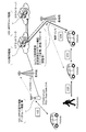
- FIG. 2 is a diagram showing an example of an overall image of V2X communication.
- the cloud server has a V2X APP server (Application Server) function.
- the cloud server is connected to the core network via a network such as the Internet.
- the core network is composed of devices having a control function for V2X communication.
- Multiple base stations are connected to the core network.
- the base station (RAN) has a function of wirelessly communicating with a terminal device (an example of UE, Vehicle in the example of FIG. 2) (for example, a Uu link connection function using a Uu interface).
- the base station has a function of supporting direct communication (for example, side link communication) such as V2V communication and V2P communication.
- An RSU (Road Side Unit) is placed on the road as an infrastructure.
- RSUs There are two possible RSUs, a base station type RSU and a UE type RSU.
- the RSU has, for example, a V2X APP providing function, a data relay function, and the like.
- V2X use case> As wireless communication for automobiles, the development of DSRC (Dedicated Short Range Communication) based on 802.11p has been mainly promoted so far. However, in recent years, the standardization of "LTE-based V2X", which is an LTE (Long Term Evolution) -based in-vehicle communication, has been carried out. In LTE-based V2X communication, the exchange of basic safety messages and the like is supported. In recent years, with the aim of further improving V2X communication, studies on NR V2X communication using 5G technology (NR: New Radio) have been conducted.
- LTE-based V2X LTE (Long Term Evolution) -based in-vehicle communication
- FIG. 3 is a diagram showing an example of a use case of V2X communication.
- Use cases of V2V communication include forward approach warning, intersection collision prevention, emergency vehicle warning, platooning, overtaking cancellation warning, road construction warning, and the like.
- use cases of V2I communication include notification of road safety information, traffic light cooperation, parking lot assistance, billing, and the like.
- examples of use cases for V2P communication include warnings for vulnerable people.
- use cases of V2N communication include dynamic link sharing, remote driving, and in-house entertainment.
- NR V2X communication supports new use cases that require high reliability, low delay, high-speed communication, and high capacity, which could not be supported by LTE-based V2X so far.
- provision of a dynamic map, remote driving, and the like can be mentioned.
- sensor data sharing in which sensor data is exchanged between vehicles and road vehicles, and platening use cases for platooning.
- Use cases and requirements for these NR V2X communications are described in 3GPP TR22.886 and the like. The following (1) to (4) are brief explanations of some use cases.
- platooning As a use case of NR V2X communication, platooning can be mentioned.
- the platooning means that a plurality of vehicles form a platoon and travel in the same direction. Information for controlling platooning is exchanged between the vehicle leading the platooning and other vehicles.
- NR V2X communication is used to exchange this information. By exchanging information using NR V2X communication, it is possible to further reduce the inter-vehicle distance of platooning.
- NR V2X communication examples include semi-autonomous driving and fully automatic driving.
- the RSU shares the recognition / recognition information obtained from the sensors and the like owned by the RSU to the surrounding vehicles.
- each vehicle can adjust the trajectory and operation of the vehicle in synchronization and coordination.
- each vehicle can also share the driving intention and intention with neighboring vehicles.
- Remote Driving Use cases for NR V2X communication include remote control by remote control and V2X applications.
- Remote control is used, for example, for people who cannot drive or in dangerous areas.
- Cloud computing-based maneuvers can also be used for public transport, where routes and roads are fixed to some extent. In this use case, high reliability and low transmission delay are required for communication.
- V2X communication of this embodiment may be a use case other than these.
- Examples of the target link include a Uu link which is a link between an infrastructure such as a base station or RSU and a terminal, and a PC5 link (side link) which is a link between terminals.
- the following (1) to (9) are examples of main enhancements.
- Examples of channel format enhancement in (1) include Flexible numerology, Short TTI (Transmission Time Interval), multi-antenna support, and Waveform. Further, examples of the enhancement of the side link feedback communication in (2) include HARQ, CSI (Channel Status Information) and the like.
- V2X Operation Scenario> Next, an example of a V2X communication operation scenario will be described.
- V2N communication communication between the base station and the terminal was simple only by DL / UL communication, but in V2V communication, various communication paths can be considered.
- each scenario will be described using an example of V2V communication, but the same communication operation can be applied to V2P and V2I.
- the communication destination is not a vehicle (Vehicle) but a pedestrian (Pedestrian), a base station, or an RSU.
- FIG. 4 is an example of V2V communication according to scenario 1.
- a car an example of UE
- a car an example of UE
- the side link is a communication link between terminals such as PC5.
- the side link may be called a V2V communication link, a V2P communication link, a V2I communication link, or the like, in addition to the PC5.
- the car and the car communicate directly using side link communication without going through the radio access network.
- E-UTRAN Evolved Universal Terrestrial Radio Access Network
- the radio access network is not limited to E-UTRAN.
- the radio access network may be NG-RAN.
- FIG. 5 is an example of V2V communication according to scenario 2.
- the car an example of UE
- the car communicate via a radio access network.
- data is transmitted from one car to a plurality of cars.
- Uu indicates a Uu interface.
- the Uu interface is a wireless interface between a terminal and a base station.
- UL indicates uplinks and DL downlinks.
- E-UTRAN is also shown as a wireless access network, but the wireless access network is not limited to E-UTRAN.
- the radio access network may be NG-RAN.
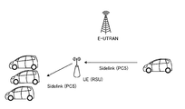
- FIG. 6 is an example of V2V communication according to scenario 3.
- the car and the car communicate with the RSU via a radio access network.
- data is transmitted from one car to a plurality of cars.
- one car and the RSU are connected by side link communication.
- E-UTRAN is shown as a wireless access network, but the wireless access network is not limited to E-UTRAN.
- the radio access network may be NG-RAN.
- the RSU is shown as a device that operates as a UE, but the RSU is not limited to this.
- the RSU may operate as a RAN or as a part (eg gNB-DU, RRH, RRU) of the RAN (E-UTRAN or NG-RAN) of FIG.
- FIG. 7 is an example of V2V communication according to scenario 4.
- the car and the car communicate with the RSU via a radio access network.
- a radio access network In the example of FIG. 7, a plurality of vehicles and an RSU are connected by side link communication.
- E-UTRAN is also shown as a wireless access network, but the wireless access network is not limited to E-UTRAN.
- the radio access network may be NG-RAN.
- the RSU is shown as a device that operates as a UE, but the RSU is not limited to this.
- the RSU may operate as a RAN or as a part (eg gNB-DU, RRH, RRU) of the RAN (E-UTRAN or NG-RAN) of FIG.
- FIG. 8 is an example of V2V communication according to scenario 5.
- the car and the car communicate via the RSU, not via the radio access network.
- the RSU shown in FIG. 8 is a fixed station type RSU.
- the radio access network may be NG-RAN.
- the RSU is shown as a device that operates as a UE, but the RSU is not limited to this.
- the RSU may operate as a RAN or as a part (eg gNB-DU, RRH, RRU) of the RAN (E-UTRAN or NG-RAN) of FIG.
- FIG. 9 is an example of V2V communication according to scenario 6.
- the car and the car communicate via the RSU, not via the radio access network.
- the RSU shown in FIG. 9 is a mobile station type RSU.
- an LTE wireless frame when used in NR V2X communication, for example, the requirements in scenarios 1 to 6 described above may not be satisfied.
- NR V2X communication for example, when performing high-speed large-capacity communication (eMBB) or performing low-latency high-reliability (URLLC) communication for one vehicle (an example of UE), etc. It is required to support requests of different service types.
- eMBB high-speed large-capacity communication
- URLLC low-latency high-reliability
- NR V2X communication for example, when performing URLLC communication, it is desirable to use the NR numerology and frame configuration instead of using the LTE frame configuration. That is, in NR V2X communication, it is desirable to use NR numerology and frame configuration for NR side link communication in order to satisfy the demands of different services.
- FIG. 10 is a diagram showing a frame configuration of NR.
- one radio frame is composed of 10 ms.
- One radio frame is composed of two half frames.
- the time interval of one half frame is 5 ms.
- one half frame is composed of five subframes.
- the time interval for one subframe is 1 ms.
- one subframe is composed of one or more slots.
- FIG. 10 shows an example in which one subframe is composed of four slots.
- the time interval of each slot differs depending on the numerology (OFDM numerology).
- numerology is defined by a combination of subcarrier spacing (SCS: Subcarrier Spacing) and cyclic prefix (CP: Cyclic Prefix).
- SCS Subcarrier Spacing
- CP Cyclic Prefix
- FIG. 11 is a diagram showing an example of subcarrier interval setting.
- the subcarrier spacing is defined by a power of 2 relative to 15 kHz.
- the subcarrier interval is set to 15 kHz, 30 kHz, 60 kHz, 120 kHz, and 240 kHz.
- the number of slots per subframe is one. That is, when the subcarrier interval is 15 kHz, the slot time interval is 1 ms, when it is 30 kHz, it is 0.5 ms, and when it is 60 kHz, it is 0.25 ms, which is 120 kHz.
- the number of symbols in one slot is 14 in the case of the normal CP (cyclic prefix) and 12 in the case of the extended CP.
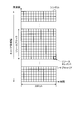
- FIG. 12 is a diagram showing an example of a resource grid.
- the transmitted physical signal and physical channel are represented by a resource grid in their respective numerologies and subcarriers.
- a resource grid is defined by multiple resource elements.
- One resource element at a given antenna port is represented by one subcarrier and one symbol. That is, the index of the resource element at a predetermined antenna port can be represented by a combination of the subcarrier index and the symbol index.
- a resource block (RB: Resource Block) is defined as a unit in the frequency axis direction.
- One resource block is composed of 12 subcarriers that are continuous in the frequency axis direction.
- resource blocks there are a common resource block (CRB: Common Resource Block), a physical resource block (PRB: Physical Resource Block), and a virtual resource block (VRB: Virtual Resource Block).
- CRB Common Resource Block
- PRB Physical Resource Block
- VRB Virtual Resource Block
- a common resource block is a resource block defined by a predetermined frequency bandwidth and a predetermined numerology. The common resource block starts from Point A in all numerologies. The frequency specified at point A is the center of subcarrier # 0 of common resource block # 0 in all numerologies.
- a physical resource block is a resource block defined within a predetermined frequency bandwidth part.
- a virtual resource block is a logical resource block.
- the virtual resource block is used, for example, when mapping a signal after precoding of PDSCH (Physical Downlink Shared Channel) or PUSCH (Physical Uplink Shared Channel) to a physical resource block.
- PDSCH Physical Downlink Shared Channel
- PUSCH Physical Uplink Shared Channel
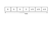
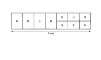
- FIGS. 13 and 14 are diagrams showing slot formats.
- DL Downlink
- UP Uplink
- Flexible Flexible
- FIGS. 13 and 14 the downlink is referred to as “D”
- U uplink
- U flexible link
- F flexible link
- the downlink may be referred to as “downlink”
- the uplink may be referred to as "uplink”.
- the terminal device when receiving information from a base station, uses the downlink symbol in the slot format to receive the information.
- the terminal device uses the uplink symbol in the slot format when transmitting information to the base station.
- the terminal device can be used for either transmission or reception of information with or from the base station for flexible symbols in slot format.
- the flexible symbol may be used as a downlink and uplink switching section (Switching Period) or guard section (Guard Period).
- the state of each symbol in the slot format is set by the information transmitted from the base station.
- TDD setting information common to terminal devices cell specific
- RRC Radio Resource Control
- SIB1 SystemInformationBlockType1
- RRCSetup message RRCReconfiguration message
- the state of each symbol is specified in (for example, TDD-UL-DL-ConfigurationCommon) or TDD setting information (TDD-UL-DL-ConfigDedicated) for each terminal device (UE specific).
- TDD setting information common to the terminal devices includes the following information (1) to (5).
- the state of each symbol may be specified by the slot format index transmitted by DCI (eg DCI format 2_0).
- the slot format index is a slot format index indicating a combination of states of 14 symbols.
- the slot format index is specified for each slot.
- the format that specifies the slot format is also called a slot format indicator (SFI).
- SFI slot format indicator
- the terminal device sets or changes uplinks, downlinks, and flexible symbols on a symbol-by-symbol basis, and recognizes symbols to be used (Consider) based on the above-mentioned TDD setting information and the slot format index specified by DCI. Can be done.
- the state of each symbol may be determined by a slot format specified by a combination of RRC signaling and DCI (e.g. DCI format 2_0).
- one or more Slot Formats may be preset by RRC signaling, and one or more Slot Formats to be used by the UE may be determined by SFI_Index (s) included in DCI format 2_0.
- the one or more SlotFormats may be included in one or a plurality of SlotFormatCombinations included in the RRC signaling.
- the terminal device sets or changes the uplink, downlink, and flexible symbol for each symbol by the combination of RRC signaling and DCI (eg DCI format 2_0), and recognizes the symbol to be used (Consider). Can be done.
- the slot format set in the terminal device may be a kind of Slot configuration set in the terminal device. That is, in the present invention, the slot format may be referred to as Slot configuration.
- the Slot configuration here includes setting information regarding one or more symbols in one or more slots.
- the setting information relating to one or more symbols includes information relating to the symbols described above or later (parameters of RRC and DCI).
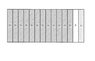
- 13 and 14 show slot formats that represent the states of 14 symbols.
- the 1st to 12th symbols are downlink symbols (D)
- the 13th symbol is a flexible symbol (F)
- the 14th symbol is an uplink symbol (U).
- the SFI for designating the slot format shown in FIG. 13 is "DDDDDDDDDDDFU" in order from the first symbol of the slot.
- HARQ-ACK corresponding to PDSCH can be transmitted and received in the same slot.
- the first symbol is the downlink symbol (D)
- the second symbol is the flexible symbol (F)
- the third to 14th symbols are the uplink symbols (U). It is shown that.
- the SFI for designating the slot format shown in FIG. 14 is "DFUUUUUUUUUUUU" in order from the first symbol of the slot.
- PUSCH corresponding to UL grant can be transmitted and received in the same slot.
- a subframe for uplink communication may be used for side link communication in the LTE frame configuration. That is, while the conventional LTE V2X communication is set in subframe units, the NR V2X communication has an advantage that it can be set in symbol units.
- the base station has at least one symbol when at least one symbol included in the slot configuration set in the terminal device is a symbol for performing communication other than side link communication.
- Information for use by the terminal device as a symbol for performing side link communication is transmitted to the terminal device.
- the terminal device can perform side link communication using the slot format of NR. That is, by using the NR slot format, it is possible to satisfy the requirements of various services in NR V2X communication, so that high communication performance can be realized.
- symbol for performing communication other than side link communication is, for example, a symbol for performing uplink communication (uplink symbol) or a flexible symbol capable of performing uplink communication or downlink communication. Although it is a symbol (flexible symbol), the details of these symbols will be described later.
- information for the terminal device to use as a symbol for performing side link communication includes, for example, information in a slot format in which a symbol for performing side link communication is set, or side linking an existing symbol. Information for use in communication, but details of these will also be described later.
- FIG. 15 is a diagram showing a configuration example of the information processing system 1 according to the embodiment of the present disclosure.
- the information processing system 1 shown in FIG. 15 is a mobile communication system including a plurality of communication devices (mobile device, terminal device) capable of side-link communication.
- the information processing system 1 is, for example, a wireless communication system using NR (New Radio) wireless access technology (RAT: Radio Access Technology). This wireless communication system is also called 5GS (5th Generation System). At this time, the information processing system 1 is not limited to the mobile phone communication system, and may be, for example, an intelligent transport system (ITS). The information processing system 1 is not limited to the cellular communication system, and may be, for example, another wireless communication system such as a wireless LAN (Local Area Network) system, an aeronautical wireless system, or a space wireless communication system.
- NR New Radio
- 5GS Fifth Generation System
- the information processing system 1 may provide an application processing execution function (for example, an edge function) to the mobile device via a wireless network using NR wireless access technology.
- NR is a kind of cellular communication technology, and enables mobile communication of a mobile device by arranging a plurality of areas covered by the base station device in a cell shape.
- the NR includes NRAT (New Radio Access Technology) and FEUTRA (Further EUTRA).
- NRAT New Radio Access Technology
- FEUTRA Frether EUTRA
- a single base station may manage a plurality of cells.
- the cell corresponding to NR is sometimes referred to as an NR cell.
- NR is the next generation (5th generation) wireless access technology (RAT) of LTE (4th generation communication including LTE-Advanced, LTE-Advanced Pro).
- RAT wireless access technology
- LTE 4th generation communication including LTE-Advanced, LTE-Advanced Pro
- NR is a wireless access technology that can support various use cases including eMBB (Enhanced Mobile Broadband), mMTC (Massive Machine Type Communications) and URLLC (Ultra-Reliable and Low Latency Communications).
- eMBB Enhanced Mobile Broadband
- mMTC Massive Machine Type Communications
- URLLC Ultra-Reliable and Low Latency Communications
- the NR base station can be referred to as an NGRAN (Next Generation RAN) node.
- NGRAN refers to RAN (RAN with a reference point with 5GC) when the core network is 5GC (5G Core). That is, NGRAN may include gNodeB (gNB) and ng-eNodeB (ng-eNB). Further, in NR, the mobile device may be referred to as a UE (User Equipment).
- gNB gNodeB
- ng-eNB ng-eNodeB
- UE User Equipment
- the information processing system 1 includes a management device 10, a base station device 20, a base station device 30, a terminal device 40, and a mobile device 50.
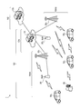
- FIG. 16 is a diagram showing a specific configuration example of the information processing system 1.
- the information processing system 1 may have a cloud server device CS, but it does not have to be an essential component.
- the network N1 is composed of these plurality of devices constituting the information processing system 1.
- the network N1 is, for example, a wireless network.
- network N1 is a mobile communication network configured by using wireless access technology such as NR.
- the network N1 is composed of a radio access network RAN and a core network CN.
- the device in the figure may be considered as a device (Logical node) in a logical sense. That is, a part of the devices in the figure may be realized by a virtual machine (VM: Virtual Machine), a container (Container), a docker (Docker), etc., and they may be mounted on physically the same hardware.
- VM Virtual Machine
- Container Container
- Docker docker
- the cloud server device CS is a processing device (for example, a server device) connected to the network N2.
- the cloud server device CS is a server host computer that processes a request from a client computer (for example, a mobile device 50).
- the cloud server device CS may be a PC server, a midrange server, or a mainframe server.
- the network N2 is a communication network connected to the network N1 via a gateway device (for example, UPF, S-GW or P-GW). That is, the network N2 is Data Network (DN).
- the network N2 is a communication network such as the Internet, a regional IP (Internet Protocol) network, and a telephone network (for example, a fixed telephone network and a mobile telephone network).
- the cloud server device can be rephrased as a server device, a processing device, or an information processing device.
- the management device 10 is a device that manages a wireless network.
- the management device 10 is a device that functions as an AMF (Access and Mobility Management Function).
- the management device 10 and the gateway device form a part of the core network CN.
- the core network CN is a network owned by a predetermined entity (subject) such as a mobile communication operator.
- the core network CN is 5GC (5G Core network).
- the predetermined entity may be the same as the entity that uses, operates, and / or manages the base station devices 20 and 30, or may be different.
- the management device 10 may have a gateway function.
- the management device 10 has a function as an UPF (User Plane Function).
- the management device 10 may be SMF, PCF, UDM, or the like.
- the core network CN may include SMF, PCF, UDM, and the like.
- the management device 10 is connected to each of the plurality of base station devices 20 and the plurality of base station devices 30. For example, in the case of 5GS, there is an N2 reference point between the AMF (10) and the NG-RAN (20, 30), and the AMF (10) and the NG-RAN (20, 30) are connected via the NG interface. Logically connected to each other.
- the management device 10 may manage the communication between the base station device 20 and the base station device 30. For example, the management device 10 manages the position of the mobile device 50 in the network N1 for each mobile device 50 in an area unit (eg Tracking Area, RAN Notification Area) composed of a plurality of cells. ..
- area unit eg Tracking Area, RAN Notification Area
- the management device 10 determines which base station device (or cell) the mobile device 50 is connected to, which base station device (or cell) is in the communication area, and the like. Each device 50 may be grasped and managed in cell units.
- the cell provided by the base station is called a Serving cell.
- Serving cells include PCell (Primary Cell) and SCell (Secondary Cell).
- Dual Connectivity eg EUTRA-EUTRA Dual Connectivity, EUTRA-NR Dual Connectivity (ENDC), EUTRA-NR Dual Connectivity with 5GC, NR-EUTRA Dual Connectivity (NEDC), NR-NR Dual Connectivity
- UE eg terminal device 40, When provided to the mobile device 50), the PCell and SCell (s) provided by the MN (Master Node) are called the Master Cell Group.
- the Serving cell may include a PS Cell (Primary Secondary Cell or Primary SCG Cell). That is, when Dual Connectivity is provided to the UE, PSCell and SCell (s) provided by SN (Secondary Node) are called Secondary Cell Group (SCG).
- PS Cell Primary Secondary Cell or Primary SCG Cell
- PSCell and SCell (s) provided by SN are called Secondary Cell Group (SCG).
- SCG Secondary Cell Group
- One Downlink Component Carrier and one Uplink Component Carrier may be associated with one cell.
- the system bandwidth corresponding to one cell may be divided into a plurality of bandwidth parts (Bandwidth Part). In this case, one or a plurality of Bandwidth Parts may be set in the UE, and one Bandwidth Part may be used in the UE as an Active BWP.
- the radio resources for example, frequency band, numerology (subcarrier spacing), slot format (Slot configuration) that can be used by the mobile device 50 may differ for each cell, each component carrier, or each BW
- the base station device 20 is a wireless communication device that wirelessly communicates with the terminal device 40 and the mobile device 50.
- the base station device 20 is a device that constitutes a network in V2N communication.
- the base station device 20 is a type of communication device.
- the base station device 20 may be a device corresponding to a radio base station (Base Station, Node B, eNB, gNB, etc.) or a radio access point (Access Point).
- a radio base station Base Station, Node B, eNB, gNB, etc.
- Access Point radio access point
- 3GPP Access when the base station apparatus is a wireless access point (Access Point), it may be referred to as Non-3GPP Access.
- the base station apparatus 20 may be a radio relay station (Relay Node). Further or instead, the base station apparatus 20 may be an optical overhanging apparatus called RRH (Remote Radio Head). Further or instead, when the base station apparatus is gNB, the base station apparatus may be referred to as a combination of gNB CU (Central Unit) and gNB DU (Distributed Unit), or any of these.
- the gNB CU (Central Unit) hosts multiple upper layers (eg RRC, SDAP, PDCP) of the Access Stratum for communication with the UE.
- gNB-DU hosts multiple lower layers (eg RLC, MAC, PHY) of the Access Stratum.
- RRC signaling may be generated by gNB CU, while DCI may be generated by gNB-DU.
- the base station of the wireless communication system may be referred to as a base station device.
- the base station device 20 may be configured to be capable of wireless communication with another base station device 20 and the base station device 30.
- the devices may be connected by an X2 interface.
- the devices may be connected by an Xn interface.
- a plurality of base station devices 20 and 30 are a combination of a gNB CU (Central Unit) and a gNB DU (Distributed Unit), the devices may be connected by an F1 interface.
- the message information (RRC signalling or DCI information) described later may be communicated between the plurality of base station devices 20 and 30 (for example, via the X2, Xn, and F1 interfaces).
- the wireless access technology used by the base station device 20 may be a cellular communication technology or a wireless LAN technology. Of course, the wireless access technology used by the base station apparatus 20 is not limited to these, and may be another wireless access technology. Further, the wireless communication used by the base station device 20 may be wireless communication using radio waves, or wireless communication (optical wireless) using infrared rays or visible light.
- the base station device 30 is a wireless communication device that wirelessly communicates with the terminal device 40 and the mobile device 50. It is a device that constitutes an infrastructure in V2I communication.
- the base station device 30 is a kind of communication device like the base station device 20.
- the base station device 30 is, for example, a device corresponding to a wireless base station (Base Station, Node B, eNB, gNB, etc.) or a wireless access point (Access Point).
- the base station device 30 may be a wireless relay station.
- the base station device 30 may be a road base station device such as an RSU (Road Side Unit).
- the base station device 20 may be an optical overhanging device called RRH (Remote Radio Head).
- the base station device 30 may be configured to be capable of wireless communication with another base station device 30 and the base station device 20.
- the wireless access technology used by the base station device 30 may be a cellular communication technology or a wireless LAN technology.
- the wireless access technology used by the base station apparatus 20 is not limited to these, and may be another wireless access technology.
- the wireless communication used by the base station device 30 may be wireless communication using radio waves, or wireless communication (optical wireless) using infrared rays or visible light.
- the base station devices 20 and 30 may be able to communicate with each other via a base station device-core network interface (for example, NG Interface, S1 Interface, etc.). This interface may be wired or wireless. Further, the base station devices may be able to communicate with each other via an interface between the base station devices (for example, Xn Interface, X2 Interface, etc.). This interface may be wired or wireless.
- a base station device-core network interface for example, NG Interface, S1 Interface, etc.
- This interface may be wired or wireless.
- the base station devices may be able to communicate with each other via an interface between the base station devices (for example, Xn Interface, X2 Interface, etc.). This interface may be wired or wireless.
- the base station devices 20 and 30 can be used, operated, and / or managed by various entities.
- the entities include a mobile network operator (MNO: Mobile Network Operator), a virtual mobile network operator (MVNO: Mobile Virtual Network Operator), a virtual mobile communication enabler (MVNE: Mobile Virtual Network Enabler), and a neutral host.
- MNO Mobile Network Operator
- MVNO Mobile Virtual Network Operator
- MVNE Virtual Mobile Network Enabler
- NTN Neutral Host Network
- operators enterprises, educational institutions (school corporations, local government education committees, etc.), real estate (buildings, condominiums, etc.) managers, individuals, etc. can be assumed.
- the subject of use, operation, and / or management of the base station devices 20 and 30 is not limited thereto.
- the base station devices 20 and 30 may be installed and / or operated by one business operator, or may be installed and / or operated by one individual.
- the installation / operation entity of the base station device 20 is not limited to these.
- the base station devices 20 and 30 may be jointly installed and operated by a plurality of businesses or a plurality of individuals.
- the base station devices 20 and 30 may be shared facilities used by a plurality of businesses or a plurality of individuals. In this case, the installation and / or operation of the equipment may be carried out by a third party different from the user.
- a base station device includes not only a donor base station but also a relay base station (also referred to as a relay station or a relay station device).
- a base station includes not only a structure having a function of a base station but also a device installed in the structure.
- the structure is, for example, a building such as a skyscraper, a house, a steel tower, a station facility, an airport facility, a port facility, or a stadium.
- the concept of structure includes not only buildings but also non-building structures such as tunnels, bridges, dams, fences, and iron pillars, and equipment such as cranes, gates, and wind turbines.
- the concept of structures includes not only structures on land (above ground in a narrow sense) or underground, but also structures on water such as piers and mega floats, and structures underwater such as ocean observation facilities.
- the base station device can be rephrased as a processing device or an information processing device.
- the base station devices 20 and 30 may be fixed stations or may be movably configured base station devices (mobile stations).
- the base station devices 20 and 30 may be devices installed on the mobile body or may be the mobile body itself.
- a relay station device having mobility can be regarded as base station devices 20 and 30 as a mobile station.
- devices that are originally mobile capable devices such as vehicles, drones (Aerial Vehicles), and smartphones and that are equipped with the functions of base station devices (at least some of the functions of base station devices) are also bases as mobile stations.
- station devices 20 and 30 corresponds to station devices 20 and 30.
- the mobile body may be a mobile terminal such as a smartphone or a mobile phone.
- the moving body may be a moving body (for example, a vehicle such as a car, a bicycle, a bus, a truck, a motorcycle, a train, a linear motor car, etc.) that moves on land (ground in a narrow sense), or in the ground (for example, a vehicle).
- it may be a moving body (for example, a subway) moving in a tunnel.
- the moving body may be a moving body moving on water (for example, a ship such as a passenger ship, a cargo ship, or a hovercraft), or a moving body moving underwater (for example, a submersible, a submarine, an unmanned submarine, etc.).
- the moving body may be a moving body moving in the atmosphere (for example, an aircraft such as an airplane, an airship, or a drone (Aerial Vehicle)), or a moving body moving outside the atmosphere (for example, an artificial satellite, space). It may be an artificial celestial body such as a ship, a space station, or a spacecraft).
- the base station devices 20 and 30 may be ground base station devices (ground station devices) installed on the ground.
- the base station devices 20 and 30 may be base station devices arranged on a structure on the ground, or may be base station devices installed on a mobile body moving on the ground.
- the base station devices 20 and 30 may be an antenna installed in a structure such as a building and a signal processing device connected to the antenna.
- the base station devices 20 and 30 may be a structure or a moving body itself. "Ground" is not only on land (ground in a narrow sense) but also on the ground in a broad sense including underground, water, and water.
- the base station devices 20 and 30 are not limited to the ground base station devices.
- the base station devices 20 and 30 may be non-ground base station devices (non-ground station devices) capable of floating in the air or in space.
- the base station devices 20 and 30 may be an aircraft station device or a satellite station device.
- the aircraft station device is a wireless communication device that can float in the atmosphere (including the stratosphere) such as aircraft.
- the aircraft station device may be a device mounted on an aircraft or the like, or may be an aircraft itself.
- the concept of an aircraft includes not only heavy aircraft such as airplanes and gliders, but also light aircraft such as balloons and airships.
- the concept of an aircraft includes not only heavy aircraft and light aircraft, but also rotary-wing aircraft such as helicopters and autogyros.
- the aircraft station device (or the aircraft on which the aircraft station device is mounted) may be an unmanned aerial vehicle such as a drone.
- unmanned aerial vehicle also includes unmanned aerial vehicles (UAS: Unmanned Aircraft Systems) and tethered unmanned aerial vehicles (tethered UAS).
- unmanned aerial vehicle includes a light unmanned aerial vehicle system (LTA: Lighter than Air UAS) and a heavy unmanned aerial vehicle system (HTA: Heavier than Air UAS).
- LTA Lighter than Air UAS
- HTA Heavy unmanned aerial vehicle system
- HAPs High Altitude UAS Platforms
- the satellite station device is a wireless communication device that can float outside the atmosphere.
- the satellite station device may be a device mounted on a space mobile body such as an artificial satellite, or may be a space mobile body itself.
- the satellites that serve as satellite station equipment are low orbit (LEO: Low Earth Orbiting) satellites, medium orbit (MEO: Medium Earth Orbiting) satellites, geostationary (GEO: Geostationary Earth Orbiting) satellites, and high elliptical orbit (HEO: Highly Elliptical Orbiting). It may be any satellite.
- the satellite station device may be a device mounted on a low earth orbit satellite, a medium earth orbit satellite, a geostationary satellite, or a high elliptical orbit satellite.
- the size of the coverage of the base station devices 20 and 30 may be as large as a macro cell or as small as a pico cell. Of course, the size of the coverage of the base station devices 20 and 30 may be extremely small, such as a femtocell. Further, the base station devices 20 and 30 may have a beamforming capability. In this case, the base station devices 20 and 30 may have cells or service areas formed for each beam.
- the terminal device 40 is a wireless communication device that wirelessly communicates with the base station device 20 or the base station device 30.
- the terminal device 40 is, for example, a mobile phone, a smart device (smartphone or tablet), a PDA (Personal Digital Assistant), or a personal computer.
- the mobile device 50 may be an M2M (Machine to Machine) device or an IoT (Internet of Things) device (for example, it may be called MTC UE, NB-IoT UE, Cat.M UE).
- the terminal device 40 is capable of side link communication with the mobile device 50 and other terminal devices 40.
- the wireless communication (including side link communication) used by the terminal device 40 may be wireless communication using radio waves or wireless communication using infrared rays or visible light (optical radio). Good.
- the mobile device 50 is a mobile wireless communication device that wirelessly communicates with the base station device 20 or the base station device 20.
- the mobile device 50 may be a wireless communication device installed on the mobile body, or may be the mobile body itself.
- the mobile device 50 may be a vehicle (Vehicle) moving on a road such as an automobile, a bus, a truck, or a motorcycle, or a wireless communication device mounted on the vehicle.
- the mobile device 50 is capable of side-link communication with the terminal device 40 and other mobile devices 50.
- the mobile device 50 can use an automatic retransmission technique such as HARQ when performing side link communication.
- the wireless communication (including side link communication) used by the mobile device 50 may be wireless communication using radio waves, or wireless communication using infrared rays or visible light (optical radio). May be good.
- a “mobile device” is a type of communication device, and is also referred to as a mobile station, mobile station device, terminal device, or terminal.
- the concept of "mobile device” includes not only a communication device configured to be movable but also a mobile body in which the communication device is installed.
- the moving body may be a mobile terminal, or may be a moving body that moves on land (ground in a narrow sense), in the ground, on the water, or in the water.
- the moving body may be a moving body such as a drone (Aerial UE) or a helicopter that moves in the atmosphere, or a moving body that moves outside the atmosphere such as an artificial satellite.
- the concept of a communication device includes not only a portable mobile device (terminal device) such as a mobile terminal, but also a device installed on a structure or a mobile body.
- the structure or the moving body itself may be regarded as a communication device.
- the concept of a communication device includes not only mobile devices (terminal devices, automobiles, etc.) but also base station devices (donor base stations, relay base stations, etc.).
- a communication device is a type of processing device and information processing device.
- the mobile device 50 and the terminal device 40 and the base station devices 20 and 30 are connected to each other by wireless communication (for example, radio wave or optical wireless).
- wireless communication for example, radio wave or optical wireless.
- the mobile device 50 and the terminal device 40 may be connected to a plurality of base station devices or a plurality of cells at the same time to perform communication. For example, when one base station device can provide a plurality of cells, the mobile device 50 or the terminal device 40 performs carrier aggregation by using one cell as a PCell and another cell as an SCell. Can be done. Further, or instead, when a plurality of base station devices can provide one or a plurality of cells, respectively, the mobile device 50 or the terminal device 40 has one base station device (MN (eg MeNB or MgNB)).
- MN base station device
- One or more cells to be managed are used as PCell or PCell and SCell (s), and one or more cells managed by the other base station device (SN (eg SeNB or SgNB)) are PSCell or PSCell and SCell (s). ) Can be used to execute DC.
- the DC may be referred to as MC (Multi Connectivity).
- the mobile device 50 and the terminal device 40 can be combined with the mobile device 50 and the terminal device 40 by the coordinated multi-point transmission and reception (CoMP) technology via the cells of different base station devices (multiple cells having different cell identifiers or the same cell identifiers). It is also possible for the plurality of base station devices to communicate with each other.
- CoMP coordinated multi-point transmission and reception
- the mobile device 50 and the terminal device 40 do not necessarily have to be devices directly used by a person.
- the mobile device 5 and the terminal device 400 may be sensors installed in a machine or the like in a factory, such as a so-called MTC (Machine Type Communication).
- the mobile device 50 may be an M2M (Machine to Machine) device or an IoT (Internet of Things) device.
- the mobile device 50 and the terminal device 40 may be devices having a relay communication function, as typified by D2D (Device to Device) and V2X (Vehicle to everything).
- the mobile device 50 and the terminal device 40 may be devices called CPE (Client Premises Equipment) used in a wireless backhaul or the like.
- CPE Customer Premises Equipment
- the management device 10 is a device that manages a wireless network.
- the management device 10 is a device that manages the communication of the base station devices 20 and 30.
- the core network CN is 5GC
- the management device 10 may be a device having a function as, for example, AMF, SMF, UPF, or the like.
- the management device 10 has an application processing execution function (for example, an edge function), and may function as a server device such as an application server. More specifically, if the UPF is located on a local area network (ie, if the UPF is a Local UPF), then a DN with an N6 reference point to and from the UPF is a device for edge computing. May be placed. Then, a device for edge computing may be included in the management device 10.
- the device for edge computing may operate as (for example, MEC (Multi access Edge Computing) Platform, MEC host, MEC application).
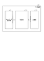
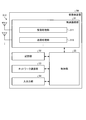
- FIG. 17 is a diagram showing a configuration example of the management device 10 according to the embodiment of the present disclosure.
- the management device 10 includes a network communication unit 11, a storage unit 12, and a control unit 13.
- the configuration shown in FIG. 17 is a functional configuration, and the hardware configuration may be different from this. Further, the functions of the management device 10 may be distributed and implemented in a plurality of physically separated configurations. For example, the management device 10 may be composed of a plurality of server devices.
- the network communication unit 11 is a communication interface for communicating with other devices.
- the network communication unit 11 may be a network interface or a device connection interface.
- the network communication unit 11 has a function of directly or indirectly connecting to the network N1.
- the network communication unit 11 may include a LAN (Local Area Network) interface such as a NIC (Network Interface Card), or may include a USB interface composed of a USB (Universal Serial Bus) host controller, a USB port, and the like. You may be.
- the network communication unit 11 may be a wired interface or a wireless interface.
- the network communication unit 11 functions as a communication means of the management device 10.
- the network communication unit 11 communicates with the base station devices 20 and 30 under the control of the control unit 13.
- the storage unit 12 is a storage device capable of reading and writing data such as a DRAM (Dynamic Random Access Memory), a SRAM (Static Random Access Memory), a flash memory, and a hard disk.
- the storage unit 12 functions as a storage means for the management device 10.
- the storage unit 12 stores, for example, the connection state of the mobile device 50.
- the storage unit 12 stores the state of the RRC (Radio Resource Control) and the state of the ECM (EPS Connection Management) of the mobile device 50.
- the storage unit 12 may function as a home memory for storing the position information of the mobile device 50.
- the control unit 13 is a controller that controls each unit of the management device 10.
- the control unit 13 is realized by, for example, a processor such as a CPU (Central Processing Unit) or an MPU (Micro Processing Unit).
- the control unit 13 is realized by the processor executing various programs stored in the storage device inside the management device 10 using a RAM (Random Access Memory) or the like as a work area.
- the control unit 13 may be realized by an integrated circuit such as an ASIC (Application Specific Integrated Circuit) or an FPGA (Field Programmable Gate Array).
- the CPU, MPU, ASIC, and FPGA can all be regarded as controllers.
- the base station device 20 is a wireless communication device that wirelessly communicates with the mobile device 50.
- the base station device 20 is a device that functions as, for example, a radio base station, a radio relay station, a radio access point, or the like.
- the base station device 20 may be an optical overhanging device such as RRH.
- the base station device 20 is a device that constitutes a network in V2N communication.
- FIG. 18A and 18B are diagrams showing a configuration example of the base station apparatus 20 according to the embodiment of the present disclosure.
- the base station apparatus 20 includes a wireless communication unit 21, a storage unit 22, a network communication unit 23, and a control unit 24.
- the configuration shown in FIG. 18A is a functional configuration, and the hardware configuration may be different from this. Further, the functions of the base station apparatus 20 may be distributed and implemented in a plurality of physically separated configurations.
- FIG. 18B The detailed configuration of the base station apparatus 20 shown in FIG. 18A is shown in FIG. 18B.
- the wireless communication unit 21 is a wireless communication interface that wirelessly communicates with another wireless communication device (for example, a mobile device 50, a base station device 30, and another base station device 20).
- the wireless communication unit 21 operates according to the control of the control unit 24.
- the wireless communication unit 21 may support a plurality of wireless access methods.
- the wireless communication unit 21 may support both NR and LTE.
- the wireless communication unit 21 may support W-CDMA or cdma2000 in addition to LTE.
- the wireless communication unit 21 may support wireless access methods other than NR, LTE, W-CDMA, and cdma2000.
- the wireless communication unit 21 includes a reception processing unit 211, a transmission processing unit 212, and an antenna 213.
- the wireless communication unit 21 may include a plurality of reception processing units 211, transmission processing units 212, and antennas 213, respectively.
- each unit of the wireless communication unit 21 may be individually configured for each wireless access method.
- the reception processing unit 211 and the transmission processing unit 212 may be individually configured by LTE and NR.
- the reception processing unit 211 processes the uplink signal received via the antenna 213.
- the reception processing unit 211 includes a wireless reception unit 211a, a multiple separation unit 211b, a demodulation unit 211c, and a decoding unit 211d.
- the radio receiver 211a performs down-conversion, removal of unnecessary frequency components, control of amplification level, orthogonal demodulation, conversion to digital signal, removal of guard interval, and fast Fourier transform of the frequency domain signal for the uplink signal. Extract, etc.
- the multiplex separation unit 211b separates uplink channels such as PUSCH (Physical Uplink Shared Channel) and PUCCH (Physical Uplink Control Channel) and uplink reference signals from the signal output from the wireless reception unit 211a.
- the demodulation unit 211c demodulates the received signal with respect to the modulation symbol of the uplink channel by using a modulation method such as BPSK (Binary Phase Shift Keying) or QPSK (Quadrature Phase Shift Keying).
- BPSK Binary Phase Shift Keying
- QPSK Quadrature Phase Shift Keying
- the modulation method used by the demodulation unit 211c may be 16QAM (Quadrature Amplitude Modulation), 64QAM, or 256QAM.
- the decoding unit 211d performs decoding processing on the coded bits of the demodulated uplink channel.
- the decoded uplink data and uplink control information are output to the control unit 24.
- the transmission processing unit 212 performs the transmission processing of the downlink control information and the downlink data.
- the transmission processing unit 212 includes a coding unit 212a, a modulation unit 212b, a multiplexing unit 212c, and a wireless transmission unit 212d.
- the coding unit 212a encodes the downlink control information and the downlink data input from the control unit 24 by using a coding method such as block coding, convolutional coding, or turbo coding. In the case of NR, the coding unit 212a may perform coding by Polar coding or coding by Low Density Parity Check (LDPC) Coding.
- the modulation unit 212b modulates the coding bits output from the coding unit 212a by a predetermined modulation method such as BPSK, QPSK, 16QAM, 64QAM, 256QAM and the like.
- the multiplexing unit 212c multiplexes the modulation symbol of each channel and the downlink reference signal and arranges them in a predetermined resource element.
- the wireless transmission unit 212d performs various signal processing on the signal from the multiplexing unit 212c.
- the radio transmitter 212d converts to the time domain by fast Fourier transform, adds a guard interval, generates a baseband digital signal, converts to an analog signal, orthogonal modulation, up-conversion, removes an extra frequency component, and so on. Performs processing such as power amplification.
- the signal generated by the transmission processing unit 212 is transmitted from the antenna 213.
- the storage unit 22 is a storage device that can read and write data such as DRAM, SRAM, flash memory, and hard disk.
- the storage unit 22 functions as a storage means for the base station device 20.
- the network communication unit 23 is a communication interface for communicating with other devices (for example, management device 10, other base station device 20, base station device 30, cloud server device CS, etc.).
- the network communication unit 23 has a function of directly or indirectly connecting to the network N1.
- the network communication unit 23 includes a LAN interface such as a NIC.
- the network communication unit 23 may be a wired interface or a wireless interface.
- the network communication unit 23 functions as a network communication means of the base station device 20.
- the network communication unit 23 communicates with other devices (for example, the management device 10, the cloud server device CS, etc.) under the control of the control unit 24.
- the configuration of the network communication unit 23 may be the same as that of the network communication unit 11 of the management device 10.
- the control unit 24 is a controller that controls each unit of the base station device 20.
- the control unit 24 is realized by, for example, a processor (hardware processor) such as a CPU (Central Processing Unit) or an MPU (Micro Processing Unit).
- the control unit 24 is realized by the processor executing various programs stored in the storage device inside the base station device 20 using a RAM (Random Access Memory) or the like as a work area.
- the control unit 24 may be realized by an integrated circuit such as an ASIC (Application Specific Integrated Circuit) or an FPGA (Field Programmable Gate Array).
- the CPU, MPU, ASIC, and FPGA can all be regarded as controllers.
- the control unit 24 may be divided into a plurality of functional blocks indicating each function of the control unit 24.
- the functional block of the control unit 24 may be a software block or a hardware block.
- each of the above-mentioned functional blocks may be one software module realized by software (including a microprocessor), or may be one circuit block on a semiconductor chip (die).
- each functional block may be one processor or one integrated circuit.
- the method of configuring the functional block is arbitrary. The operation of the control unit 24 will be described in detail later.
- the base station device 30 is a wireless communication device that wirelessly communicates with the mobile device 50.
- the base station device 30 is a device that functions as, for example, a radio base station, a radio relay station, a radio access point, or the like.
- the base station device 30 may be a road base station device such as an RSU, or an optical overhang device such as an RRH.
- the base station device 30 is a device that constitutes an infrastructure in V2I communication.
- FIG. 19 is a diagram showing a configuration example of the base station device 30 according to the embodiment of the present disclosure.
- the base station device 30 includes a wireless communication unit 31, a storage unit 32, a network communication unit 33, and a control unit 34.
- the configuration shown in FIG. 19 is a functional configuration, and the hardware configuration may be different from this. Further, the functions of the base station apparatus 30 may be distributed and implemented in a plurality of physically separated configurations.
- the wireless communication unit 31 is a wireless communication interface that wirelessly communicates with other wireless communication devices (for example, mobile device 50, base station device 20, other base station device 30).
- the wireless communication unit 31 operates according to the control of the control unit 34.
- the wireless communication unit 31 includes a reception processing unit 311, a transmission processing unit 312, and an antenna 313.
- the configuration of the wireless communication unit 31 (reception processing unit 311, transmission processing unit 312, and antenna 313) is the same as that of the wireless communication unit 21 (reception processing unit 211, transmission processing unit 212, and antenna 213) of the base station apparatus 20. ..
- the storage unit 32 is a storage device that can read and write data such as DRAM, SRAM, flash memory, and hard disk.
- the storage unit 32 functions as a storage means for the base station device 30.
- the configuration of the storage unit 32 is the same as that of the storage unit 22 of the base station device 20.
- the network communication unit 33 is a communication interface for communicating with other devices (for example, management device 10, base station device 20, other base station device 30, cloud server device CS, etc.).
- the network communication unit 33 has a function of directly or indirectly connecting to the network N1.
- the network communication unit 33 includes a LAN interface such as a NIC.
- the network communication unit 33 may be a wired interface or a wireless interface.
- the network communication unit 33 functions as a network communication means of the base station device 30.
- the configuration of the network communication unit 33 is the same as that of the network communication unit 23 of the base station apparatus 20.
- the control unit 34 is a controller that controls each unit of the base station device 30.
- the control unit 34 is realized by, for example, a processor such as a CPU or MPU.
- the control unit 34 is realized by the processor executing various programs stored in the storage device inside the base station device 30 with the RAM or the like as a work area.
- the control unit 34 may be realized by an integrated circuit such as an ASIC or FPGA.
- the CPU, MPU, ASIC, and FPGA can all be regarded as controllers.
- the control unit 34 may be divided into a plurality of functional blocks indicating each function of the control unit 34.
- the functional block of the control unit 34 may be a software block or a hardware block.
- each of the above-mentioned functional blocks may be one software module realized by software (including a microprocessor), or may be one circuit block on a semiconductor chip (die).
- each functional block may be one processor or one integrated circuit.
- the method of configuring the functional block is arbitrary. The operation of the control unit 34 will be described in detail later. Further, the operation of the control unit 34 may be the same as the operation of the control unit 24 described above.
- the terminal device 40 is a mobile wireless communication device.
- the terminal device 40 may be a user terminal (UE: User Equipment) such as a mobile phone or a smart device.
- UE User Equipment
- the terminal device 40 is capable of wireless communication with the base station device 20 and the base station device 30.
- the terminal device 40 is capable of side link communication with the mobile device 50 and other terminal devices 40.
- FIG. 20 is a diagram showing a configuration example of the terminal device 40 according to the embodiment of the present disclosure.
- the terminal device 40 includes a wireless communication unit 41, a storage unit 42, a network communication unit 43, an input / output unit 44, and a control unit 45.
- the configuration shown in FIG. 20 is a functional configuration, and the hardware configuration may be different from this. Further, the functions of the terminal device 40 may be distributed and implemented in a plurality of physically separated configurations. Further, in the configuration of the terminal device 40, the network communication unit 53 and the input / output unit 44 do not have to be essential components.
- the wireless communication unit 41 is a wireless communication interface that wirelessly communicates with other wireless communication devices (for example, the base station device 20 and the base station device 30).
- the wireless communication unit 41 operates according to the control of the control unit 45.
- the wireless communication unit 41 corresponds to one or a plurality of wireless access methods.
- the wireless communication unit 41 corresponds to both NR and LTE.
- the wireless communication unit 41 may support W-CDMA and cdma2000 in addition to NR and LTE. Further, the wireless communication unit 21 may support communication using NOMA.
- the wireless communication unit 41 includes a reception processing unit 411, a transmission processing unit 412, and an antenna 413.
- the wireless communication unit 41 may include a plurality of reception processing units 411, transmission processing units 412, and antennas 413, respectively.
- each unit of the wireless communication unit 41 may be individually configured for each wireless access method.
- the reception processing unit 411 and the transmission processing unit 412 may be individually configured by LTE and NR.
- the reception processing unit 411 processes the downlink signal received via the antenna 413.
- the reception processing unit 411 includes a wireless reception unit 411a, a multiple separation unit 411b, a demodulation unit 411c, and a decoding unit 411d.
- the radio receiver 411a performs down-conversion, removal of unnecessary frequency components, control of amplification level, orthogonal demodulation, conversion to digital signal, removal of guard interval, and fast Fourier transform of the frequency domain signal for the downlink signal. Extract, etc.
- the multiplex separation unit 411b separates the downlink channel, the downlink synchronization signal, and the downlink reference signal from the signal output from the radio reception unit 411a.
- the downlink channel is, for example, a channel such as PBCH (Physical Broadcast Channel), PDSCH (Physical Downlink Shared Channel), PDCCH (Physical Downlink Control Channel).
- the demodulation unit 211c demodulates the received signal with respect to the modulation symbol of the downlink channel by using a modulation method such as BPSK, QPSK, 16QAM, 64QAM, 256QAM.
- the decoding unit 411d performs decoding processing on the coded bits of the demodulated downlink channel.
- the decoded downlink data and downlink control information are output to the control unit 45.
- the downlink synchronization signal may include SSB (SS / PBCH Block).
- the downlink reference signal may include CSI-RS and DMRS.
- the transmission processing unit 412 performs the transmission processing of the uplink control information and the uplink data.
- the transmission processing unit 412 includes a coding unit 412a, a modulation unit 412b, a multiplexing unit 412c, and a wireless transmission unit 412d.
- the coding unit 412a encodes the uplink control information and the uplink data input from the control unit 45 by using a coding method such as block coding, convolutional coding, or turbo coding. In the case of NR, the coding unit 412a may perform coding by Polar coding or coding by Low Density Parity Check (LDPC) Coding.
- the modulation unit 412b modulates the coding bits output from the coding unit 412a by a predetermined modulation method such as BPSK, QPSK, 16QAM, 64QAM, 256QAM.
- the multiplexing unit 412c multiplexes the modulation symbol of each channel and the uplink reference signal and arranges them in a predetermined resource element.
- the wireless transmission unit 412d performs various signal processing on the signal from the multiplexing unit 412c.
- the radio transmitter 412d converts to the time domain by inverse fast Fourier transform, adds a guard interval, generates a baseband digital signal, converts to an analog signal, orthogonal modulation, up-converts, and removes extra frequency components. , Performs processing such as power amplification.
- the signal generated by the transmission processing unit 412 is transmitted from the antenna 413.
- the storage unit 42 is a storage device that can read and write data such as DRAM, SRAM, flash memory, and hard disk.
- the storage unit 42 functions as a storage means for the terminal device 40.
- the network communication unit 43 is a communication interface for communicating with other devices.
- the network communication unit 43 is a LAN interface such as a NIC.
- the network communication unit 43 has a function of directly or indirectly connecting to the network N1.
- the network communication unit 43 may be a wired interface or a wireless interface.
- the network communication unit 43 functions as a network communication means of the terminal device 40.
- the network communication unit 43 communicates with other devices according to the control of the control unit 45.
- the input / output unit 44 is a user interface for exchanging information with the user.
- the input / output unit 44 is an operation device for the user to perform various operations such as a keyboard, a mouse, operation keys, and a touch panel.
- the input / output unit 44 is a display device such as a liquid crystal display (Liquid Crystal Display) or an organic EL display (Organic Electroluminescence Display).
- the input / output unit 44 may be an audio device such as a speaker or a buzzer.
- the input / output unit 44 may be a lighting device such as an LED (Light Emitting Diode) lamp.
- the input / output unit 44 functions as an input / output means (input means, output means, operation means, or notification means) of the terminal device 40.
- the control unit 45 is a controller that controls each unit of the terminal device 40.
- the control unit 45 is realized by, for example, a processor such as a CPU or MPU.
- the control unit 45 is realized by the processor executing various programs stored in the storage device inside the terminal device 40 using the RAM or the like as a work area.
- the control unit 45 may be realized by an integrated circuit such as an ASIC or FPGA.
- the CPU, MPU, ASIC, and FPGA can all be regarded as controllers.
- the control unit 45 may be divided into a plurality of functional blocks indicating each function of the control unit 45.
- the functional block of the control unit 45 may be a software block or a hardware block.
- each of the above-mentioned functional blocks may be one software module realized by software (including a microprocessor), or may be one circuit block on a semiconductor chip (die).
- each functional block may be one processor or one integrated circuit.
- the method of configuring the functional block is arbitrary. The operation of the control unit 45 will be described in detail later.
- the mobile device 50 is a mobile wireless communication device.
- the mobile device 50 is a vehicle such as an automobile, or a wireless communication device mounted on the vehicle.
- the mobile device 50 may be a mobile terminal device such as a mobile phone or a smart device.
- the mobile device 50 can wirelessly communicate with the base station device 20 and the base station device 30. Further, the mobile device 50 can perform side link communication with the terminal device 40 and other mobile devices 50.
- FIG. 21 is a diagram showing a configuration example of the mobile device 50 according to the embodiment of the present disclosure.
- the mobile device 50 includes a wireless communication unit 51, a storage unit 52, a network communication unit 53, an input / output unit 54, and a control unit 55.
- the configuration shown in FIG. 21 is a functional configuration, and the hardware configuration may be different from this. Further, the functions of the mobile device 50 may be distributed and implemented in a plurality of physically separated configurations.
- the wireless communication unit 51 is a wireless communication interface that wirelessly communicates with other wireless communication devices (for example, the base station device 20 and the base station device 30).
- the wireless communication unit 51 operates according to the control of the control unit 55.
- the wireless communication unit 51 corresponds to one or a plurality of wireless access methods.
- the wireless communication unit 51 corresponds to both NR and LTE.
- the wireless communication unit 51 may support W-CDMA and cdma2000 in addition to LTE.
- the wireless communication unit 21 supports communication using NOMA.
- the wireless communication unit 51 includes a reception processing unit 511, a transmission processing unit 512, and an antenna 513.
- the wireless communication unit 51 may include a plurality of reception processing units 511, transmission processing units 512, and antennas 513, respectively.
- each unit of the wireless communication unit 51 may be individually configured for each wireless access method.
- the reception processing unit 511 and the transmission processing unit 512 may be individually configured by LTE and NR.
- the reception processing unit 511 processes the downlink signal received via the antenna 513.
- the reception processing unit 511 includes a wireless reception unit 511a, a multiple separation unit 511b, a demodulation unit 511c, and a decoding unit 511d.
- the radio receiver 511a performs down-conversion, removal of unnecessary frequency components, control of amplification level, orthogonal demodulation, conversion to digital signal, removal of guard interval, and fast Fourier transform of the frequency domain signal for the downlink signal. Extract, etc.
- the multiplex separation unit 511b separates the downlink channel, the downlink synchronization signal, and the downlink reference signal from the signal output from the radio reception unit 511a.
- the downlink channel is, for example, a channel such as PBCH, PDSCH, PDCCH, or the like.
- the demodulation unit 211c demodulates the received signal with respect to the modulation symbol of the downlink channel by using a modulation method such as BPSK, QPSK, 16QAM, 64QAM, 256QAM.
- the decoding unit 511d performs decoding processing on the coded bits of the demodulated downlink channel.
- the decoded downlink data and downlink control information are output to the control unit 55.
- the transmission processing unit 512 performs the transmission processing of the uplink control information and the uplink data.
- the transmission processing unit 512 includes a coding unit 512a, a modulation unit 512b, a multiplexing unit 512c, and a wireless transmission unit 512d.
- the coding unit 512a encodes the uplink control information and the uplink data input from the control unit 55 by using a coding method such as block coding, convolutional coding, or turbo coding.
- the modulation unit 512b modulates the coding bits output from the coding unit 512a by a predetermined modulation method such as BPSK, QPSK, 16QAM, 64QAM, 256QAM.
- the multiplexing unit 512c multiplexes the modulation symbol of each channel and the uplink reference signal and arranges them in a predetermined resource element.
- the wireless transmission unit 512d performs various signal processing on the signal from the multiplexing unit 512c.
- the radio transmitter 512d converts to the time domain by inverse fast Fourier transform, adds a guard interval, generates a baseband digital signal, converts to an analog signal, orthogonal modulation, up-converts, and removes extra frequency components. , Performs processing such as power amplification.
- the signal generated by the transmission processing unit 512 is transmitted from the antenna 513.
- the storage unit 52 is a storage device that can read and write data such as DRAM, SRAM, flash memory, and hard disk.
- the storage unit 52 functions as a storage means for the mobile device 50.
- the network communication unit 53 is a communication interface for communicating with other devices.
- the network communication unit 53 is a LAN interface such as a NIC.
- the network communication unit 53 has a function of directly or indirectly connecting to the network N1.
- the network communication unit 53 may be a wired interface or a wireless interface.
- the network communication unit 53 functions as a network communication means for the mobile device 50.
- the network communication unit 53 communicates with other devices according to the control of the control unit 55. In the configuration of the terminal device 40, the network communication unit 53 does not have to be an indispensable component.
- the input / output unit 54 is a user interface for exchanging information with the user.
- the input / output unit 54 is an operation device for the user to perform various operations such as a keyboard, a mouse, operation keys, and a touch panel.
- the input / output unit 54 is a display device such as a liquid crystal display or an organic EL display.
- the input / output unit 54 may be an audio device such as a speaker or a buzzer.
- the input / output unit 54 may be a lighting device such as an LED lamp.
- the input / output unit 54 functions as an input / output means (input means, output means, operation means, or notification means) of the mobile device 50.
- the input / output unit 54 does not have to be an indispensable component in the configuration of the terminal device 40.
- the control unit 55 is a controller that controls each unit of the mobile device 50.
- the control unit 55 is realized by, for example, a processor (hardware processor) such as a CPU or MPU.
- the control unit 55 is realized by the processor executing various programs stored in the storage device inside the mobile device 50 with the RAM or the like as a work area.
- the control unit 55 may be realized by an integrated circuit such as an ASIC or FPGA.
- the CPU, MPU, ASIC, and FPGA can all be regarded as controllers.
- the control unit 55 may be divided into a plurality of functional blocks indicating each function of the control unit 24.
- the functional block of the control unit 55 may be a software block or a hardware block.
- each of the above-mentioned functional blocks may be one software module realized by software (including a microprocessor), or may be one circuit block on a semiconductor chip (die).
- each functional block may be one processor or one integrated circuit.
- the method of configuring the functional block is arbitrary. The operation of the control unit 55 will be described in detail later.
- the mobile device 50 may have a moving function.
- the mobile device 50 may have a power unit such as an engine and can move by its own power.
- the mobile device 50 does not necessarily have to have a moving function.
- the mobile device 50 may be a device that is retrofitted to a device having a moving function (for example, a vehicle such as an automobile).
- the mobile device 50 may be a navigation system device that is retrofitted to the automobile.
- the “base station” shown below is a base station including the above-mentioned base station device 20 or base station device 30. Further, the “terminal device” shown below is the terminal device 40 or the mobile device 50 described above. That is, the operation of the base station shown below is the operation of the control unit 24 included in the base station apparatus 20 or the operation of the control unit 34 included in the base station apparatus 30. The operation of the terminal device shown below is the operation of the control unit 45 included in the terminal device 40 or the operation of the control unit 55 included in the mobile device 50.
- the following (1) to (3) are newly constructed so that the terminal device performs side link communication using the slot format of NR. Details of these (1) to (3) will be described in order.
- (1) New design of slot format (2) Slot format setting method (3) Slot format change method (symbol rewriting)
- New slot format design> In the present embodiment, in NR V2X communication, the base station newly designs a slot format for performing side link communication. Specifically, the base station newly designs the slot format according to the methods shown in (1A) and (1B) below. (1A) Method of defining a new symbol for side-link communication (1B) Method of using an existing symbol for side-link communication
- the base station can use the symbol for uplink communication (uplink symbol), the symbol for downlink communication (downlink symbol), as the state of each symbol in the slot format. It is possible to set four states, a symbol for flexibility (flexible symbol) and a symbol for side link communication (side link symbol).
- the base station can use the symbol for uplink communication (uplink symbol), the symbol for downlink communication (downlink symbol), as the state of each symbol in the slot format. It is possible to set four states, a symbol for flexibility (flexible symbol) and a symbol for side link communication (side link symbol).
- (1A-1) Symbol that can be executed only by side link communication
- (1A-3) Symbol that can selectively execute side link communication or uplink communication
- FIG. 22 is a diagram showing an example of a slot format including a symbol for performing side link communication.
- the 1st to 4th symbols are downlink symbols (D)
- the 5th to 7th symbols are side link symbols (S).
- the terminal device performs downlink communication with the 1st to 4th symbols in the slot and sidelink communication with the 5th to 7th symbols. That is, in the case of the slot format shown in FIG. 22, in the 5th to 7th symbols, only the side link communication can be performed, and the downlink communication and the uplink communication cannot be performed.
- FIG. 23 is a diagram showing an example of a slot format including a symbol for performing side link communication.
- the 1st to 4th symbols are the downlink symbol (D)
- the 5th to 7th symbols are the uplink symbol (U) or the side link symbol (S).
- the terminal device performs downlink communication with the 1st to 4th symbols in the slot, and uplink communication or sidelink communication with the 5th to 7th symbols. That is, in the case of the slot format shown in FIG.
- the 5th to 7th symbols it is possible to select whether to use each symbol for uplink communication or side link communication.
- the selection of whether to use for uplink communication or side-link communication may be specified by the base station, or may be determined and selected by the terminal device.
- the 5th to 7th symbols shown in FIG. 23 cannot be used for downlink communication.
- FIG. 24 is a diagram showing an example of a slot format including a symbol for performing side link communication.
- the 1st to 4th symbols are the downlink symbol (D)
- the 5th to 7th symbols are the uplink symbol (U) and the side link symbol (S).
- the terminal device performs downlink communication with the 1st to 4th symbols in the slot, and performs uplink communication and sidelink communication with the 5th to 7th symbols at the same time.
- the uplink communication and the side link communication may be set to different resource elements (that is, different subcarriers) or may be set to the same resource element.
- code multiplexing CDMA: Code Division Multiple Access
- IDMA Interleave Division Multiple Access
- spatial multiplexing may be performed.
- the 5th to 7th symbols shown in the above cannot be used for downlink communication.
- the slot formats described in (1A-1) to (1A-3) are examples.
- FIG. 25 is a diagram showing an example of a slot format including a symbol for performing side link communication.
- the 1st to 4th symbols are downlink symbols (D)
- the 5th to 7th symbols are uplink symbols (“(U)”) capable of sidelink communication.
- the terminal device performs downlink communication with the 1st to 4th symbols in the slot, and any of the following (a) to (c) is used for the 5th to 7th symbols.
- A Sidelink communication
- b Uplink communication
- the base station notifies the terminal device which of the above-mentioned communications (a) to (c) the terminal device performs, and a specific example of this notification will be described later.
- FIG. 26 is a diagram showing an example of a slot format including a symbol for performing side link communication.
- the 1st to 4th symbols are downlink symbols (D)
- the 5th to 7th symbols are flexible symbols (“(F)”) capable of sidelink communication.
- the terminal device performs downlink communication with the 1st to 4th symbols in the slot, and any of the following (a) to (d) is used for the 5th to 7th symbols.
- A Sidelink communication
- the base station notifies the terminal device which of the above (a) to (d) is to be communicated, and a specific example of this notification will be described later.
- the base station sets the same slot format for all terminal devices existing in the same cell.
- the base station can set the slot format for each cell by any of the following three methods.
- (2A-1) Set by RRC signaling
- (2A-2) Set by Group Common PDCCH (Group Common PDCCH)
- (2A-3) In combination with RRC signaling and PDCCH (including group common) (DCI: Downlink Control Information) Configuration
- the base station sets the slot format individually for each terminal device existing in the cell.
- the base station can set the slot format for each terminal by any of the following three methods.
- (2B-1) Set by UE specific RRC signaling (Dedicated signaling)
- (2B-2) Set by PDCCH (DCI)
- (2B-3) Set by combination with RRC signaling and PDCCH (DCI: Downlink Control Information)
- the slot When the format is set for each terminal, the setting method may be further divided into the following two methods.
- (2BA) When there are multiple cells set in the same UE, for each cell
- (2BB) When multiple BWPs are set in at least one cell, for each BWP
- the base station When a new symbol for side link communication is defined, the base station newly generates a slot format including a symbol for side link communication according to the definition shown in (1A) above.
- a slot format including a symbol for side link communication is newly defined in 3GPP or the like, and the base station uses an index corresponding to each slot format as slot format information.
- the newly generated slot format information is, for example, information indicating a pattern of states of 14 symbols when the number of symbols in one slot is 14.
- the base station stores a list of symbol patterns in the slot format as table information, and adds the newly generated slot format information to the table information.
- the base station sets the generated new slot format (or slot format information) for each cell, the above-mentioned (2A-1) to (2A-3), that is, RRC signaling, PDCCH ( Notify (set) to all terminal devices existing in the cell by either DCI) or a combination of RRC signaling and PDCCH (DCI).
- the base station may notify the terminal device of the state of each symbol in the newly generated slot format as it is. Specifically, when the slot format shown in FIG. 22 is newly generated, the base station notifies the terminal device of information indicating the slot format “DDDDSSS”. That is, the base station notifies the terminal device of the information in which the states of the symbols in the slot format are arranged. Further or instead, at this time, the base station may notify the corresponding Format number (range of e.g. 56-254) in order to notify the terminal device of the newly generated slot format.
- the base station may notify the corresponding Format number (range of e.g. 56-254) in order to notify the terminal device of the newly generated slot format.
- the base station may notify the assigned Slot Format Combination ID together with the information in which the symbol states are arranged. That is, when a plurality of Slot Formats are set in advance by RRC signaling, the base station generates one or a plurality of Slot Format Combinations including one or a plurality of Slot Formats, and sets an ID for each Slot Format Combination.
- the ID (SlotFormatCombinationID) may be notified to the terminal device.
- the base station may include the generated new slot format (or slot format information) in the above-mentioned TDD setting information (TDD-UL-DL-ConfigurationCommon) and notify it. Further or instead, the above-mentioned TDD setting information may be extended in order to notify the terminal device of the generated new slot format.
- TDD-UL-DL-ConfigurationCommon may be named TDD-UL-DL-SL-ConfigurationCommon.
- the base station when the base station sets the generated new slot format for each terminal, the above-mentioned (2B-1) to (2B-3), that is, UE specific RRC signaling (Dedicated signaling), PDCCH ( Each terminal device is individually notified (set) by either DCI) or a combination of RRC signaling and PDCCH (DCI).
- the base station may notify the terminal device of the state of each symbol in the newly generated slot format as it is, or respond to notify the terminal device of the newly generated slot format.
- the Format number (range 56-254) may be notified.
- the base station may notify the assigned Slot Format Combination ID together with the information in which the symbol states are arranged.
- the base station when a plurality of Slot Formats are set in advance by RRC signaling, the base station generates one or a plurality of Slot Format Combinations including one or a plurality of Slot Formats, and sets an ID for each Slot Format Combination.
- the ID (Slot Format Combination ID) may be notified to the terminal device.
- the base station may include the generated new slot format (or slot format information) in the above-mentioned TDD setting information (TDD-UL-DL-ConfigDedicated) and notify it. Further or instead, the above-mentioned TDD setting information may be extended in order to notify the terminal device of the generated new slot format.
- TDD-UL-DL-ConfigDedicated may be named TDD-UL-DL-SL-ConfigDedicated.
- notification (setting) can be performed by any one of the following two methods or a combination thereof. -How to newly define and notify RRC configuration-How to newly define and notify DCI for side link communication
- the base station needs to notify (set) to the terminal device which existing symbol (which uplink symbol or flexible symbol) is to be used for the side link communication among the slot formats set for the terminal device. is there.
- the base station can notify by, for example, a bitmap.
- the base station notifies the terminal device of the configuration bitmap of "1111000000000" when, for example, it indicates that the first to fourth flexible symbols can be used for side link communication.
- the terminal device can use the 1st to 4th flexible symbols in the slot format "FFFFUUUUFFFUU" for side link communication.
- the base station may notify (set) in association with the slot format number or the Slot Form Combination ID in addition to the above-mentioned bitmap "1111000000000".
- the terminal device can grasp that the bitmap of "111100000000” and the slot format "FFFFUUUUUFFFUU" correspond to each other.
- the base station has a side link communication only, an uplink communication only, and a side link communication and an uplink communication simultaneous communication. It is necessary to notify (set) which communication is to be performed to the terminal device. That is, the base station needs to indicate whether the symbol that can be (also) used for side link communication is used only for side link communication or the side link communication and the uplink communication are used together.
- the base station can notify by, for example, a bitmap. Specifically, the base station uses the first and second symbols of the slot format "FFFFUUUUFFFUU" only for side link communication, and uses the third and fourth symbols together for side link communication and uplink communication. When this is done, the bitmap of "1100xxxxxxxxxxxxxx” is notified to the terminal device. Note that "x" in the above bitmap indicates that any value of 0 or 1 may be used. As a result, the terminal device uses the first and second symbols of the slot format "FFFFUUUUFFFUU" only for side link communication, and the third and fourth symbols are used for simultaneous side link communication and uplink communication. Can be used.
- the slot format number or the Slot Format Combination ID may be associated with the bitmap "1100xxxxxxxxxxxx” in this case.
- the terminal device can grasp that "1100xxxxxxxxxxxx” and the slot format "FFFFUUUUUFFFUU" correspond to each other.
- the notification method using a bitmap is shown as an example.
- a symbol number (nbr_symbol) and a communication type (type_symbol) possible with the symbol may be associated with each symbol in the slot format to notify the terminal device.
- nbr_symbol "0101" and type_symbol "1" the bit value indicating that it is used for side link communication is assumed to be "1".
- the terminal device can use the fifth symbol in the slot format for side link communication.
- TDD setting information (TDD-UL-DL-ConfigurationCommon, TDD-UL-DL-ConfigDedicated) as an example.
- the TDD setting information may include, for example, the following information (6) and (7) regarding side link communication in addition to the above-mentioned information (1) to (5). (6) Position and number of sidelink symbols (7) All sidelinks for each symbol
- FIG. 27 is a diagram showing an example of configuration notification.
- the underlined portion in bold indicates an information element (Information Element) for which a new regulation is expected for notifying the terminal device of information regarding side link communication.
- Information Element Information Element
- “pattern3" (TDD-SL Pattern) may be newly specified in TDD-UL-DL-ConfigurationCommon.
- symbols and “bitmaps” may be selectable (CHOICE) as the pattern type.
- “oneSlot” and “twoSlot” may be set by “symbolBitmapsForSlotFormat”.
- “symbolBitmapsForSlotFormat” may indicate the above-mentioned bitmap by "oneSlot” or "twoSlot”.
- “nrofSidelinkSymbols” may be set.
- “nrofSidelinkSymbols” corresponds to "the number of sidelink symbols” among the positions and numbers of (6) sidelink symbols described above.
- All Sidelink may be newly specified in “symbols” in TDD-UL-DL-Config Dedicated.
- “nrofSidelinkSymbols” may be newly specified in “explicit” in the same “symbols”.
- nrofSidelinkSymbols may be defined as follows. That is, “nrofSidelinkSymbols” indicates the number of consistent sidelink symbols starting with the following symbol of the downlink symbol specified by nrofDownlinkSymbols.
- the concecutive sidelink symbols here may or may not overlap with some of the continuous uplink symbols, depending on the configuration and the capabilities of the UE. May be good.
- symbolBitmapsForSlotFormat may be defined as follows. That is, “symbolBitmapsForSlotFormat” indicates a bitmap symbol pattern for defining one or more sidelink symbols in one or two slots. This bitmap symbol pattern is mapped to the uplink or downlink TDD settings set on the UE (eg, the slot format described above).
- the base station decides to change the symbol and instructs the terminal device to change
- 3B The terminal device decides to change the symbol and changes the symbol.
- the base station When the base station notifies the terminal device of the slot format setting by the methods shown in (3A-1) to (3A-4) and then the predetermined information transmitted from the terminal device satisfies the predetermined rewriting conditions. Instruct the rewriting of the symbol in the set slot format by the methods shown in (3A-1) to (3A-4).
- the rewriting condition is a condition for rewriting the state of the symbol, and the details of the condition will be described later.
- the predetermined information transmitted from the terminal device includes, for example, the channel congestion status (CBR: Channel Busy Ratio), the traffic model of the terminal device, the service type of side link communication, and the priority information of communication (Priority information). ), Interference level, resource usage status, etc.
- CBR Channel Busy Ratio
- [3A-1: Change the slot format set by RRC Signaling with DCI] (Operation of base station)
- the base station changes, for example, the slot format set by RRC Signaling with DCI for side link communication.
- the base station sets the slot format in the terminal device by RRC Signaling.
- the slot format set by RRC Signaling is one or more symbols in one or more slots set by TDD setting information (TDD-UL-DL-ConfigurationCommon or TDD-UL-DL-ConfigDedicated). May be good.
- the slot format set by RRC Signaling may be one or more slot formats included in one or more SlotFormat Combination IDs.
- the base station decides to rewrite the symbol when the rewriting conditions described later are satisfied, and notifies the terminal device of the change of the symbol using DCI for side link communication. For example, the base station notifies the terminal device of the symbol number of the symbol to be changed and the state of the symbol after the change. The details of the rewriting conditions will be described later.
- the terminal device In the case of (3A-1), the terminal device first sets the slot format notified by RRC Signaling from the base station. Subsequently, when the base station notifies the change of the symbol by DCI for side link communication, the terminal device rewrites the state of the symbol in the slot format according to the notification content.
- [3A-2: Change the slot format set in DCI with RRC] (Operation of base station)
- the base station notifies the terminal device of one or more slot formats by DCI format 2_0 including SFI that specifies one or more slot formats (eg SlotFormatCombination).
- the base station decides to rewrite the symbol when the rewriting conditions described later are satisfied, and changes the symbol by, for example, a predetermined RRC configuration (various setting information (for example, TDD setting information) described above). Notice.
- the base station notifies the terminal device of the symbol number of the symbol to be changed, the slot containing the symbol to be changed, and the state of the symbol after the change.
- the terminal device sets one or more slot formats (eg SlotFormatCombination) specified by SFI in DCI format 2_0 transmitted from the base station. Subsequently, the terminal device rewrites the symbol state according to the RRC configuration from the base station. That is, the specific symbol in the slot indicated by the RRC configuration is rewritten so as to be in the changed symbol state indicated by the RRC configuration.
- slot formats eg SlotFormatCombination
- the base station notifies the terminal device existing in the cell of the slot format to be set by the Cell Specific RRC (for example, TDD-UL-DL-ConfigurationCommon).
- the base station decides to rewrite the symbol when the rewriting conditions described later are satisfied, and the UE Specific RRC (for example, TDD-UL-DL-ConfigDedicated) is used to individually rewrite the symbol for the terminal device to be rewritten. Notify you of symbol changes.
- the base station when using TDD-UL-DL-ConfigDedicated, the base station may be set so that the symbol for side link communication is included in the plurality of symbols to be set. Further, the base station may transmit TDD-UL-DL-ConfigDedicated, which includes a symbol for side link communication in the setting, to the terminal device after transmitting TDD-UL-DL-ConfigurationCommon.
- TDD-UL-DL-ConfigDedicated which includes a symbol for side link communication in the setting
- the terminal device after transmitting TDD-UL-DL-ConfigurationCommon.
- TDD-UL-DL-ConfigDedicated if TDD-UL-DL-ConfigurationCommon is already set, the UE can reconfigure / override its own configuration with TDD-UL-DL-ConfigDedicated. Good.
- the terminal device In the case of (3A-3), the terminal device first sets the slot format specified by TDD-UL-DL-ConfigurationCommon received from the base station. Subsequently, the terminal device decides to rewrite the symbol when the rewriting conditions described later are satisfied, and when receiving TDD-UL-DL-ConfigDedicated from the base station, the slot specified by TDD-UL-DL-ConfigDedicated Rewrite the symbols in the box so that they are in the state of the symbols specified in the TDD-UL-DL-ConfigDedicated.
- [3A-4: Change the slot format set in Group Commnon PDCCH with UE Specific DCI] (Operation of base station)
- the base station first notifies the terminal device of the slot format to be set by the Group Common PDCCH.
- the slot format specified by the Group Common PDCCH may be one or more slot formats indicated by the SlotFormatCombination identified by the SlotFormat Combination ID corresponding to the SFI specified in DCI format 2_0.
- the base station notifies the change of the symbol by the UE Specific DCI.
- the UE Specific DCI may be a DCI for side link communication.
- the DCI for side link communication may include information indicating a symbol to be changed (rewritten), a slot including the symbol, and a state of the symbol after the change.
- the terminal device sets one or more slot formats indicated by the SlotFormat Combination ID identified by the SlotFormat Combination ID corresponding to the SFI specified by DCI format 2_0 received from the base station. Subsequently, the terminal device rewrites the symbol in the slot format based on the DCI for side link communication received from the base station.
- the DCI for side link communication here may include information indicating a symbol to be changed (rewritten), a slot including the symbol, and a state of the symbol after the change.
- the terminal device decides to change the symbol and changes the symbol] Secondly, the terminal device may decide to change the symbol and change the symbol. That is, instead of receiving instructions from the base station, the terminal device itself determines whether to change the symbol.
- the operations of the base station and the terminal device in this case are as follows. First, an operation example of the base station is as follows.
- the base station sets the rewriting conditions described later and notifies the terminal device.
- the base station notifies the terminal device of the rewriting condition by, for example, RRC or DCI.
- the base station may notify all the terminal devices in the cell of the set rewriting conditions, may notify the set rewriting conditions in a specific group unit including a plurality of terminal devices in the cell, or may notify the terminal devices. Each may be notified individually.
- the Dedicated channel may be used for notification.
- the terminal device rewrites the symbol in the slot format when the information related to the communication in the own device satisfies the rewriting condition set by the base station. Then, when the symbol is rewritten, the terminal device notifies the base station and other terminal devices that the symbol has been rewritten.
- the terminal device notifies the base station that the symbol has been rewritten by, for example, PUCCH or PUSCH. Further, the terminal device transmits the PUCCH and the PUSCH by using the uplink symbol and the flexible symbol which have not been rewritten among the symbols in the slot format.
- the terminal device notifies another terminal device that the symbol has been rewritten by, for example, PSCCH, PSCH, or PSFCH.
- the terminal device transmits PSCCH, PSCH, or PSFCH using an uplink symbol that has not been rewritten, a flexible symbol, or a side link symbol among the symbols in the slot format.
- the other terminal device that has received this notification may or may not rewrite the symbol of its own slot format in order to perform side link communication with the terminal device. For example, when the other terminal device is outside the cell of the base station, the other terminal device rewrites the current slot format to the new slot format notified from the terminal device, and communicates using the new slot format. As a result, side link communication can be performed with the terminal device when the other terminal device cannot communicate with the base station.
- the other terminal device when the other terminal device is in the cell of the base station, it does not rewrite the current slot format and communicates using the current slot format. That is, when the other terminal device can communicate with the base station, the symbol for side link communication is not rewritten in order to give priority to the communication with the base station.
- the rewriting conditions may be set by the base station as described above, or may be defined in advance in the standard.
- CBR Channel Busy Ratio
- QoS Quality of Service
- the base station decides to rewrite the symbol when the CBR reported from the terminal device satisfies the preset rewriting condition. For example, when the base station determines that the communication channel of the side link communication is congested based on CBR, the base station rewrites the uplink symbol or the flexible symbol in the current slot format to the side link symbol or the uplink / side link symbol. As a result, the resources capable of side-link communication increase, so that the communication congestion situation can be improved.
- the terminal device determines the symbol rewriting by itself, the terminal device determines the rewriting of the symbol based on the CBR acquired by the terminal device and rewrites the symbol.
- the base station decides to rewrite the symbol when the traffic model reported from the terminal device satisfies a preset rewriting condition. Specifically, the base station predicts the transmission timing of the terminal device and the amount of resources required for transmission based on the traffic model, and rewrites the symbols so as to have an appropriate slot format that matches the prediction result. For example, when the packet size of the side link communication of the terminal device is large, the base station (or the terminal device) rewrites the uplink symbol or the flexible symbol to the side link symbol or the uplink / side link symbol. As a result, the amount of resources for side-link communication increases, so that appropriate communication can be performed even when the packet size is large.
- the base station may reduce the total number of side link symbols when transmitting a plurality of times in a predetermined slot format, for example, when the transmission cycle of the terminal device is long. That is, when the transmission cycle of the terminal device is long, the side link symbols in the slot format for a plurality of times may be relatively reduced.
- the terminal device determines the symbol rewriting by itself, the terminal device determines to rewrite the symbol based on the traffic model acquired by the terminal device and rewrites the symbol.
- FIG. 28 is a diagram showing an example of symbol rewriting.
- Max delay maximum delay
- any uplink symbol shown in FIG. 27 (14th symbol in FIG. 27) is rewritten to a symbol capable of sidelink communication (either sidelink communication alone or sidelink communication and uplink communication may be used in combination).
- side link communication can be performed at the 14th symbol, so that the maximum delay request in side link communication can be satisfied.
- the terminal device determines the symbol rewriting by itself, the terminal device determines the rewriting of the symbol based on the QoS request and rewrites the symbol.
- the base station determines the rewriting of the symbol based on the Priority information indicating the priority of communication. For example, it is assumed that the base station sets a symbol for simultaneous sidelink and uplink communication in the terminal device in the current slot format. In such a case, the base station rewrites the side link symbol or the uplink symbol to the symbol of the priority communication type (communication type with high priority) based on the priority information of the terminal device. As a result, simultaneous communication of side link communication and uplink communication can be avoided, and priority communication among side link communication and uplink communication can be performed with priority.
- the priority communication type communication type with high priority
- FIG. 29 is a diagram showing a symbol rewriting pattern in the slot format.
- the side link symbol is indicated by “S”
- the downlink symbol is indicated by “D”
- the uplink symbol is indicated by “U”
- the flexible symbol is indicated by “F”.
- the combinations in which the symbols can be rewritten (“Y” shown in FIG. 29) are as follows.
- the terminal device basically performs uplink communication using the rewritten symbol, for example, in the same slot.
- side link communication is performed using the rewritten symbol. This makes it possible to support use cases such as URLLC communication and resource preemption, for example.
- the terminal device transmits information to a base station by, for example, uplink communication, and at the same time, the side link. Information is transmitted to other terminals by communication. This makes it possible to support, for example, a use case in which HARQ Feedback is simultaneously transmitted to a base station and other terminals.
- the 13th uplink symbol is rewritten to the side link symbol.
- the 11th to 15th consecutive symbols can be used for side link communication.
- the 13th uplink symbol in the slot format of "DDDDDDDDDFFUFF" can be rewritten to the side link symbol (or flexible symbol) to reach the 11th to 15th. Consecutive symbols can be used for sidelink communication.
- the terminal device can determine whether to perform uplink communication or side link communication based on the above-mentioned Priority information.
- the terminal device receives PDSCH from the base station and transmits HARQ Feedback 4 ms later.
- uplink communication is performed with the base station and based on the priority information.
- side link communication is performed with other terminal devices.
- the terminal device performs simultaneous communication of uplink communication and side link communication when the priorities of uplink communication and side link communication are the same. In this way, by rewriting the uplink symbol to a symbol capable of performing uplink communication and side link communication, it is possible to flexibly support communication according to the priority of information.
- the side link symbol included in the slot format newly generated by the above (1A) is a flexible symbol, or a symbol capable of performing side link communication and uplink communication (side link or uplink symbol, or side.
- the traffic model of side link communication is changed. For example, when the terminal device changes from sending periodic traffic to sending non-periodic traffic, when the side link symbol that was planned to be used is no longer used due to this change, the resource of the side link symbol is used. It will be wasted.
- the terminal device performs side link communication by rewriting the existing side link symbol with a flexible symbol or a symbol capable of performing side link communication and uplink communication in response to a change in traffic. Even if it disappears, uplink communication and downlink communication can be performed, so that waste of resources can be minimized.
- the receiving terminal needs to perform Blind Decoding in order to determine whether the transmission from the transmitting terminal is uplink communication or side link communication, and as a result, the Complexity of Decoding may increase. For example, by rewriting a symbol (sidelink or uplink) capable of performing sidelink communication or uplink communication with an uplink symbol or a sidelink symbol, it is not necessary for the receiving terminal to perform decoding for discrimination.
- the receiving terminal rewrites a symbol capable of performing side-link communication and uplink communication (side-link and uplink symbol) to an uplink symbol or a side-link symbol, so that Energy Evaluation is performed when Sidelink Measurement is performed. It is possible to avoid situations where the result of is not appropriate.
- the transmitting terminal performs uplink communication or side link communication (side link or uplink), so that Power Sharing cannot be performed well, or uplink communication and side link communication (side link and). Even if Inter Subcarrier Interference occurs with each other at the time of uplink), the problem that occurs in such a case can be solved by rewriting the uplink symbol or the side link symbol.
- the Slot configuration set in the UE is one or more downlink symbols, uplink symbols, flexible symbols and sidelinks. It may be set to include a symbol.
- the above-mentioned DCI format 2_0 indicates that the slot format set in the terminal device includes one or more downlink symbols, uplink symbols, flexible symbols and side link symbols, either directly or indirectly via SFI. May be shown.
- SFI may be associated with SlotFormat Combination ID on a one-to-one basis. SlotFormat Combination ID may correspond to one or more slot formats.
- the terminal device uses a flexible symbol (or a set thereof) to transmit SL (side link) on the Physical Sidelink Channel or SL. You may receive it.
- the Slot Configuration configured on the terminal device by TDD-UL-DL-ConfigurationCommon and TDD-UL-DL-ConfigDedicated contains one or more flexible symbols, or TDD-UL-DL-ConfigurationCommon and TDD-UL- DL-Config Dedicated is not provided to the terminal device
- B) The terminal device detects (receives) DCI format 2_0 including SFI for providing the slot format, and the DCI format 2_0 indicates a plurality of symbols (or a set thereof) as flexible symbols.
- the terminal device does not detect the DCI format (eg DCI format 1_0, DCI format 1_1, or DCI format 0_1) for receiving PDSCH and CSI-RS, or the terminal device does not detect PUSCH, PUCCH, PRACH, or Does not detect DCI format (eg DCI format 0_0, DCI format 0_1, DCI format 1_0, DCI format 1_1, DCI format 2_3) or RAR UL grant for transmitting SRS, and (d) by the terminal device.
- the terminal device rewrites or reconfigures the flexible symbol (or its set) to the symbol (or its set) for SL transmission or SL reception in the Physical Sidelink Channel, and reconfigures the Physical Sidelink Channel. May be transmitted or received.
- the terminal device recognizes (Consider) the flexible symbol (or its set) as a symbol (or its set) for SL transmission or SL reception on the Physical Sidelink Channel, or the flexible symbol (or its set).
- the set) may be assumed to be a symbol (or a set thereof) for SL transmission or SL reception on the Physical Sidelink Channel, and then SL transmission or SL reception on the Physical Sidelink Channel may be performed.
- the conditions (a) to (d) in this case are for determining whether to rewrite (or instruct) the symbol by the method shown in (3A-1) to (3A-4) described above. It may be used as a condition (rewriting condition) of.
- the terminal device uses the flexible symbol (or a set thereof) to perform SL transmission or SL reception on the Physical Sidelink Channel. May be good.
- the Slot configuration set in the terminal device by TDD-UL-DL-ConfigurationCommon and TDD-UL-DL-ConfigDedicated contains one or more flexible symbols, or TDD-UL-DL-ConfigurationCommon and TDD-UL- DL-Config Dedicated is not provided to the terminal device
- B) The terminal device does not receive DCI format 2_0 including SFI for providing the slot format, and (c) receives DCI format X_Y indicating SL transmission or SL reception on the Physical Sidelink Channel by the terminal device.
- the terminal device rewrites or reconfigures the flexible symbol (or its set) to the symbol (or its set) for SL transmission or SL reception on the Physical Sidelink Channel, and uses the Physical Sidelink Channel.
- SL transmission or SL reception may be performed.
- the terminal device considers the flexible symbol (or its set) as a symbol (or its set) for SL transmission or SL reception on the Physical Sidelink Channel, or the flexible symbol (or its set).
- the set) may be assumed to be a symbol (or a set thereof) for SL transmission or SL reception on the Physical Sidelink Channel, and then SL transmission or SL reception on the Physical Sidelink Channel may be performed.
- the conditions (a) to (c) are for determining whether to rewrite the symbol by the method shown in (3A-1) to (3A-4) described above (or instruct). It may be used as a condition (rewriting condition) of.
- the above-mentioned Physical Sidelink Channel may be any one of the following (a) to (d), or may include any one of (a) to (d).
- PSBCH Physical Sidelink Broadcast Channel
- PSCCH Physical Sidelink Control Channel
- PSDCH Physical Sidelink Discovery Channel
- PSSCH Physical Sidelink Shared Channel
- DCI format X_Y for the terminal device described above to transmit or receive the Physical Sidelink Channel in SL may be defined as a new DCI format.
- DCI format X_Y may be DCI format 3_0 or DCI format 5_0.
- DCI format X_Y may include the following information (a) to (c).
- SCI format 0 fields may include the following information (c1) to (c3).
- C1 Frequency hopping flag (C2) Resource block assignment and hopping resource allocation (C3) Time resource pattern
- the target to which this embodiment is applied is not limited to V2X communication.
- This embodiment can also be applied to use cases other than V2X communication using side link communication.
- application examples of this embodiment include D2D communication and MTC communication.
- the present embodiment can also be applied to moving cells, relay communications, and the like. That is, in the present embodiment, V2X communication does not have to be an essential component.
- the present embodiment is also applicable to multi-carrier communication in which side-link communication is performed using a plurality of carriers.
- control device for controlling the management device 10, the base station device 20, the base station device 30, the terminal device 40, or the mobile device 50 of the present embodiment may be realized by a dedicated computer system or is general-purpose. It may be realized by a computer system.
- a program for executing the above operation is stored and distributed in a computer-readable recording medium such as an optical disk, a semiconductor memory, a magnetic tape, or a flexible disk.
- the control device is configured by installing the program on a computer and executing the above-mentioned processing.
- the control device may be a management device 10, a base station device 20, a base station device 30, a terminal device 40, or an external device (for example, a personal computer) of the mobile device 50.
- the control device is a device inside the management device 10, the base station device 20, the base station device 30, the terminal device 40, or the mobile device 50 (for example, the control unit 13, the control unit 24, the control unit 34, the control unit). 45, or the control unit 55) may be used.
- the above communication program may be stored in a disk device provided in a server device on a network such as the Internet so that it can be downloaded to a computer or the like.
- the above-mentioned functions may be realized by collaboration between the OS (Operating System) and the application software.
- the part other than the OS may be stored in a medium and distributed, or the part other than the OS may be stored in the server device so that it can be downloaded to a computer or the like.
- each component of each device shown in the figure is a functional concept, and does not necessarily have to be physically configured as shown in the figure. That is, the specific form of distribution / integration of each device is not limited to the one shown in the figure, and all or part of the device is functionally or physically dispersed / physically distributed in arbitrary units according to various loads and usage conditions. It can be integrated and configured.
- the base station apparatus (for example, base station apparatus 20, base station apparatus 30) includes a communication unit (wireless communication units 21, 31) and a control unit 24. With 34.
- the communication unit (wireless communication units 21, 31) communicates with the terminal device (terminal device 40, mobile device 50).
- the control units 24 and 34 perform side link communication with at least one symbol when at least one symbol included in the slot format set in the terminal device is a symbol for performing communication other than side link communication.
- Information for use by the terminal device as a symbol of is transmitted to the terminal device.
- the terminal device can perform side-link communication using the slot format of NR, it is possible to satisfy the requirements of various services in NR V2X communication, and high communication performance can be realized.
- the present technology can also have the following configurations.
- (2) The control unit The base station device according to (1) above, wherein a slot format including a symbol for performing the side link communication is generated, and the generated slot format is transmitted to the terminal device.
- (3) The control unit Information for changing a symbol for performing communication other than the side link communication included in the slot format set in the terminal device to a symbol for performing the side link communication is transmitted to the terminal device ( The base station apparatus according to 1) or (2).
- the control unit When the information reported from the terminal device satisfies a predetermined rewriting condition, the change of the symbol is determined, and the information for changing to the symbol for performing the side link communication is transmitted to the terminal device.
- the information reported from the terminal device is The base station apparatus according to (4) above, which is information on the congestion status of the channel.
- the information reported from the terminal device is The base station device according to (4) above, which is information on a traffic model of the terminal device.
- the information reported from the terminal device is The base station device according to (4) above, which is information regarding a QoS request of the terminal device.
- the information reported from the terminal device is The base station device according to (4) above, which is information on the communication priority of the terminal device.
- the control unit Information for use by the terminal device as a symbol for performing side link communication using the at least one symbol is transmitted to all the terminal devices belonging to the cell managed by the base station (1) to (8).
- the control unit Information for use by the terminal device as a symbol for performing side link communication using the at least one symbol is individually transmitted to each of the terminal devices belonging to a cell managed by the base station (1) to (1).
- the base station apparatus according to any one of 9).
- the base station device according to any one of (1) to (10) above, wherein the information for the terminal device to use as a symbol for performing side link communication using the at least one symbol is bitmap information.
- the symbol for performing the side link communication is The base station apparatus according to any one of (1) to (11) above, which is a symbol for performing only the side link communication.
- the symbol for performing the side link communication is The base station apparatus according to any one of (1) to (12) above, which is a symbol for performing side link communication or uplink communication.
- the symbol for performing the side link communication is The base station apparatus according to any one of (1) to (13) above, which is a symbol for simultaneous communication of side link communication and uplink communication.
- a control method for a base station device including control of transmitting information for use by the device to the terminal device.
- It ’s a terminal device The communication unit that communicates with the base station equipment, When at least one symbol included in the slot format set in the terminal device is a symbol for performing communication other than side link communication, the terminal uses the at least one symbol as a symbol for performing side link communication.
- a terminal device including a control unit that receives information for use by the device from the base station device.
- a method of controlling a terminal device including receiving information for use by the device from the base station device.
- Information information system 10 Management device 20, 30 Base station device 40 Terminal device 50 Mobile device 11, 23, 33, 43, 53 Network communication unit 12, 22, 32, 42, 52 Storage unit 13, 24, 34, 45 , 55 Control unit 21, 31, 41, 51 Wireless communication unit 44, 54 Input / output unit 211, 411, 411, 511 Reception processing unit 212, 312, 412, 512 Transmission processing unit 213, 313, 413, 513 Antenna
Landscapes
- Engineering & Computer Science (AREA)
- Signal Processing (AREA)
- Computer Networks & Wireless Communication (AREA)
- Mobile Radio Communication Systems (AREA)
Abstract
Description
1.はじめに
1-1.V2X通信全体像
1-2.V2Xユースケース
1-3.物理レイヤエンハンスメント
1-4.V2Xオペレーションシナリオ
1-5.本実施形態の概要
2.情報処理システムの構成
2-1.情報処理システムの全体構成
2-2.管理装置の構成
2-3.基地局装置(Network)の構成
2-4.基地局装置(Infrastructure)の構成
2-5.端末装置の構成
2-6.移動体装置の構成
3.情報処理システムの動作
3-1.スロットフォーマットの新たな設計
3-2.スロットフォーマットの設定方法
3-3.スロットフォーマットの変更方法
4.変形例
5.むすび
従来、移動体通信システムは、携帯電話、スマートフォンなどのモバイル端末向けに通信機能を提供するものであった。しかし、近年では、移動体通信システムは、自動車、ドローン、ロボット等、モバイル端末とは異なるタイプの移動体に向けた通信もサポートすることが重要になってきている。
図2は、V2X通信の全体像の一例を示す図である。図2の例では、クラウドサーバはV2XのAPPサーバ(Application Server)機能を備えている。クラウドサーバはインターネット等のネットワークを介して、コアネットワークと接続される。コアネットワークは、V2X通信の制御機能を有する装置で構成されている。コアネットワークには複数の基地局が接続されている。基地局(RAN)は、端末装置(UEの一例、図2の例ではVehicle)と無線通信をする機能(例えば、Uuインタフェースを使ったUuリンク接続機能)を備える。また、基地局は、V2V通信やV2P通信などの直接通信(例えば、サイドリンク通信)をサポートする機能を備える。なお、路上には、インフラストラクチャとしてRSU(Road Side Unit)が配置されている。RSUとしては、基地局型のRSUとUE型のRSUの二つが考えられる。RSUは、例えば、V2XのAPP提供機能やデータリレー機能等を備えている。
自動車向けの無線通信としては、これまで主に、802.11pベースのDSRC(Dedicated Short Range Communication)の開発が進められてきた。しかし、近年になり、LTE(Long Term Evolution)ベースの車載通信である“LTE-based V2X”の標準規格化が行われた。LTEベースV2X通信では、基本的なセーフティメッセージ等のやり取りなどがサポートされている。近年では、さらなるV2X通信の改善を目指して、5G技術(NR:New Radio)を用いたNR V2X通信の検討が行われている。
NR V2X通信のユースケースとして、隊列走行が挙げられる。隊列走行とは、複数の車両が隊列となって同じ方向に走行することをいう。隊列走行を主導する車と他の車との間で、隊列走行を制御するための情報がやり取りされる。この情報のやり取りにNR V2X通信が使用される。NR V2X通信を使って情報をやり取りすることにより、隊列走行の車間距離をより詰めることが可能となる。
NR V2X通信のユースケースとして、センサ関連の情報(データ処理前のRawデータや処理されたデータ)の交換が挙げられる。センサ情報は、ローカルセンサーや、周辺の車両やRSUや歩行者間のライブビデオイメージやV2Xアプリケーションサーバ等を通して集められる。車両はこれらの情報交換により、自身のセンサ情報では得られない情報を入手することができ、より広範囲の環境を認知/認識することが可能となる。このユースケースでは、多くの情報を交換する必要があるため、通信には高いデータレートが求められる。
NR V2X通信のユースケースとして、準自動走行や、完全自動走行が挙げられる。RSUは、自身が保有するセンサ等から得られた認知/認識情報を周辺車両へとシェアする。これにより、それぞれの車両は、車両の軌道や操作を同期、協調しながら調整することができる。NR V2X通信を使用することによって、それぞれの車両は、ドライビングの意図や意思を周辺車両とシェアすることも可能となる。
NR V2X通信のユースケースとして、遠隔操縦者やV2Xアプリケーションによる遠隔操縦が挙げられる。遠隔操作は、例えば、運転ができない人や危険地域に対して用いられる。ルートや走行する道がある程度決まっているような公共交通機関に対してはクラウドコンピューティングベースの操縦を用いることも可能である。このユースケースでは、高い信頼性と低い伝送遅延が通信に求められる。
上記の要求事項を達成するために、LTE V2Xから物理レイヤのさらなるエンハンスメント(強化)が必要となる。対象となるリンクは、基地局やRSUなどのインフラと端末との間のリンクであるUuリンクや端末間同士のリンクであるPC5リンク(サイドリンク)が挙げられる。次の(1)~(9)は、主なエンハンスメントの例である。
(2)サイドリンクフィードバック通信
(3)サイドリンクリソース割り当て方式
(4)車両位置情報推定技術
(5)端末間リレー通信
(6)ユニキャスト通信、マルチキャスト通信のサポート
(7)マルチキャリア通信、キャリアアグリゲーション
(8)MIMO/ビームフォーミング
(9)高周波周波数対応(例:6GHz以上)
次に、V2Xの通信オペレーションシナリオの例について述べる。V2N通信においては基地局と端末間の通信は、DL/UL通信のみでシンプルであったが、V2V通信では様々な通信経路が考えられる。以下の説明では、V2V通信の例を用いて各シナリオを説明するが、V2PやV2Iにも同様の通信オペレーションを適用可能である。その場合、通信先が車(Vehicle)ではなく、歩行者(Pedestrian)や基地局、RSUとなる。
図4は、シナリオ1に係るV2V通信の例である。シナリオ1では、車(UEの一例)と車(UEの一例)がサイドリンク通信を使って直接通信する。サイドリンクとは、PC5等の端末間の通信リンクのことである。サイドリンクは、PC5の他に、V2V通信リンク、V2P通信リンク、V2I通信リンクなどと呼ばれることもある。図4の例では、車と車が無線アクセスネットワークを介さずに、サイドリンク通信を使って直接通信している。なお、図4の例では、無線アクセスネットワークとしてE-UTRAN(Evolved Universal Terrestrial Radio Access Network)が示されているが、無線アクセスネットワークはE-UTRANに限られない。例えば無線アクセスネットワークはNG-RANであってもよい。
図5は、シナリオ2に係るV2V通信の例である。シナリオ2では、車(UEの一例)と車が無線アクセスネットワークを介して通信する。図5の例では、1の車から複数の車へデータが送信されている。なお、図5において、UuはUuインタフェースを示す。Uuインタフェースは端末と基地局間の無線インタフェースである。ULはアップリンクを示し、DLダウンリンクを示す。図5の例でも、無線アクセスネットワークとしてE-UTRANが示されているが、無線アクセスネットワークはE-UTRANに限られない。例えば無線アクセスネットワークはNG-RANであってもよい。
図6は、シナリオ3に係るV2V通信の例である。シナリオ3では、車と車がRSUと無線アクセスネットワークを介して通信する。図6の例でも、1の車から複数の車へデータが送信されている。図6の例では、1の車とRSUがサイドリンク通信で接続される。図6の例でも、無線アクセスネットワークとしてE-UTRANが示されているが、無線アクセスネットワークはE-UTRANに限られない。例えば無線アクセスネットワークはNG-RANであってもよい。また、図6では、RSUはUEとして動作する装置として示されているがこれには限られない。例えば、RSUはRANとして動作してもよいし、図6のRAN(E-UTRAN又はNG-RAN)の一部(e.g. gNB-DU, RRH, RRU)として動作してもよい。
図7は、シナリオ4に係るV2V通信の例である。シナリオ4では、車と車がRSUと無線アクセスネットワークを介して通信する。図7の例では、複数の車とRSUがサイドリンク通信で接続される。図7の例でも、無線アクセスネットワークとしてE-UTRANが示されているが、無線アクセスネットワークはE-UTRANに限られない。例えば無線アクセスネットワークはNG-RANであってもよい。また、図6では、RSUはUEとして動作する装置として示されているがこれには限られない。例えば、RSUはRANとして動作してもよいし、図6のRAN(E-UTRAN又はNG-RAN)の一部(e.g. gNB-DU, RRH, RRU)として動作してもよい。
図8は、シナリオ5に係るV2V通信の例である。シナリオ5では、車と車が、無線アクセスネットワークを介さずに、RSUを介して通信する。図8に示すRSUは固定局型のRSUである。例えば無線アクセスネットワークはNG-RANであってもよい。また、図6では、RSUはUEとして動作する装置として示されているがこれには限られない。例えば、RSUはRANとして動作してもよいし、図6のRAN(E-UTRAN又はNG-RAN)の一部(e.g. gNB-DU, RRH, RRU)として動作してもよい。
図9は、シナリオ6に係るV2V通信の例である。シナリオ6では、車と車が、無線アクセスネットワークを介さずに、RSUを介して通信する。図9に示すRSUは移動局型のRSUである。
これまでのV2X通信(例えば3GPP Rel.12又はそれ以降のV2X通信)では、LTEの無線フレーム(Radio Frame)が使われていた。例えば、従来のV2X通信では、LTEの無線フレームを使って、サイドリンクコントロールチャネル(PSCCH:Physical Sidelink Control Channel)や、サイドリンクデータチャネル(PSSCH:Physical Sidelink Shared Channel)等のサイドリンク通信が行われていた。
ここで、図10を用いて、NRのフレーム構成について説明する。図10は、NRのフレーム構成を示す図である。図10に示すように、1つの無線フレーム(radio frame)は、10msで構成される。1つの無線フレームは、2つのハーフフレームで構成される。1つのハーフフレームの時間間隔は、5msである。さらに、1つのハーフフレームは、5つのサブフレームで構成される。1つのサブフレームの時間間隔は、1msである。さらに、1つのサブフレームは、1つ以上のスロットで構成される。図10では、1つのサブフレームは、4つのスロットで構成される例を示している。また、各スロットの時間間隔は、ヌメロロジー(numerology、OFDMヌメロロジー)によって異なる。また、ヌメロロジーは、サブキャリア間隔(SCS:Subcarrier Spacing)、及びサイクリックプレフィックス(CP:Cyclic Prefix)の組み合わせによって規定される。
次に、図12を用いて、リソースグリッドについて説明する。図12は、リソースグリッドの一例を示す図である。本実施形態において、送信される物理信号や、物理チャネルは、それぞれのヌメロロジー及びサブキャリアにおいて、リソースグリッドによって表現される。リソースグリッドは、複数のリソースエレメントによって定義される。所定のアンテナポートにおける1つのリソースエレメントは、1つのサブキャリア及び1つのシンボルで表現される。つまり、所定のアンテナポートにおけるリソースエレメントのインデックスは、サブキャリアインデックスとシンボルインデックスの組み合わせで表すことができる。
次に、スロットに含まれるシンボルの状態を示すスロットフォーマットについて説明する。図13及び図14は、スロットフォーマットを示す図である。TDD(Time Division Duplex)セル(非ペアスペクトル(Unpaired spectrum))において、スロットに含まれる各シンボルは、下りリンク(DL:Downlink)、上りリンク(UP:Uplink)、又はフレキシブル(Flexible)の状態に分類することができる。図13及び図14では、下りリンクを「D」、上りリンクを「U」、フレキシブルを「F」と記載する。なお、以下では、下りリンクを「ダウンリンク」、上りリンクを「アップリンク」と記載する場合がある。
例えば、端末装置共通のTDD設定情報には、下記(1)~(5)の情報が含まれる。
(1)ダウンリンクスロットの数(e.g. nrofDownlinkSlots)及びダウンリンクシンボルの数(e.g. nrofDownlinkSymbols)
(2)アップリンクスロットの数(e.g. nrofUplinkSlots)及びアップリンクシンボルの数(e.g. nrofUplinkSymbols)
(3)アップリンク/ダウンリンク切り替えの周期の情報(e.g. DL-UL-TransmissionPeriodicity)
(4)対象となるスロットのインデックス(e.g. slotIndex)
(5)対象スロット内の各シンボルの情報。例えば、全下りリンク(all DL)、全上りリンク(all UL)、下りリンクシンボルの数(e.g. nrofDownlinkSymbols)及び上りリンクシンボルの数(e.g. nrofUplinkSymbols)
<<2.情報処理システムの構成>>
まず、図15を用いて、本開示の実施形態に係る情報処理システム1を説明する。図15は、本開示の実施形態に係る情報処理システム1の構成例を示す図である。図15に示す情報処理システム1は、サイドリンク通信が可能な複数の通信装置(移動体装置、端末装置)を備える移動体通信システムである。
図15に示すように、情報処理システム1は、管理装置10と、基地局装置20と、基地局装置30と、端末装置40と、移動体装置50と、を備える。また、図16は、情報処理システム1の具体的構成例を示す図である。情報処理システム1は、上記の構成に加えて、クラウドサーバ装置CSを有していてもよいが必須の構成要素でなくてもよい。
クラウドサーバ装置CSは、ネットワークN2に接続された処理装置(例えば、サーバ装置)である。例えば、クラウドサーバ装置CSは、クライアントコンピュータ(例えば、移動体装置50)からの要求を処理するサーバ用ホストコンピュータである。クラウドサーバ装置CSは、PCサーバであってもよいし、ミッドレンジサーバであってもよいし、メインフレームサーバであってもよい。ここで、ネットワークN2は、ネットワークN1にゲートウェイ装置(例えば、UPF、S-GWやP-GW)を介して接続された通信ネットワークである。すなわち、ネットワークN2はData Network(DN)である。また、例えば、ネットワークN2は、例えば、インターネット、地域IP(Internet Protocol)網、電話網(例えば、固定電話網、携帯電話網)等の通信ネットワークである。なお、クラウドサーバ装置は、サーバ装置、処理装置、或いは情報処理装置と言い換えることができる。
管理装置10は、無線ネットワークを管理する装置である。例えば、管理装置10は、AMF(Access and Mobility Management Function)として機能する装置である。管理装置10は、ゲートウェイ装置とともに、コアネットワークCNの一部を構成する。コアネットワークCNは、移動体通信事業者等の所定のエンティティ(主体)が有するネットワークである。例えば、コアネットワークCNは、5GC(5G Core network)である。なお、所定のエンティティは、基地局装置20、30を利用、運用、及び/又は管理するエンティティと同じであってもよいし、異なっていてもよい。
基地局装置20は、端末装置40及び移動体装置50と無線通信する無線通信装置である。基地局装置20は、V2N通信でいう、ネットワークを構成する装置である。基地局装置20は通信装置の一種である。基地局装置20は、前述の通り、無線基地局(Base Station、Node B、eNB、gNB、など)や無線アクセスポイント(Access Point)に相当する装置であってもよい。さらに又はこれに代えて、基地局装置がeNB、gNBなどである場合、3GPP Accessと称されてもよい。さらに又はこれに代えて、基地局装置が無線アクセスポイント(Access Point)である場合、Non-3GPP Accessと称されてもよい。さらに又はこれに代えて、基地局装置20は、無線リレー局(Relay Node)であってもよい。さらに又はこれに代えて、基地局装置20は、RRH(Remote Radio Head)と呼ばれる光張り出し装置であってもよい。さらに又はこれに代えて、基地局装置がgNBである場合、基地局装置はgNB CU(Central Unit)とgNB DU(Distributed Unit)の組み合わせ又はこれらのいずれかと称されてもよい。gNB CU(Central Unit)は、UEとの通信のために、Access Stratumのうち、複数の上位レイヤ(e.g. RRC, SDAP, PDCP)をホストする。一方、gNB-DUは、Access Stratumのうち、複数の下位レイヤ(e.g. RLC, MAC, PHY)をホストする。すなわち、後述されるメッセージ・情報のうち、RRC signallingはgNB CUで生成され、一方でDCIはgNB-DUは生成されてもよい。本実施形態では、無線通信システムの基地局のことを基地局装置ということがある。基地局装置20は、他の基地局装置20及び基地局装置30と無線通信可能に構成されていてもよい。例えば、複数の基地局装置20、30がeNB同士又はeNBとgNBの組み合わせである場合、当該装置間はX2インタフェースで接続されてもよい。さらに又はこれに代えて、複数の基地局装置20、30がgNB同士又はeNBとgNBの組み合わせである場合、当該装置間はXnインタフェースで接続されてもよい。さらに又はこれに代えて、複数の基地局装置20、30がgNB CU(Central Unit)とgNB DU(Distributed Unit)の組み合わせである場合、当該装置間はF1インタフェースで接続されてもよい。後述されるメッセージ・情報(RRC signalling又はDCIの情報)は複数基地局装置20、30間で(例えばX2、Xn、F1インタフェースを介して)通信されてもよい。なお、基地局装置20が使用する無線アクセス技術は、セルラー通信技術であってもよいし、無線LAN技術であってもよい。勿論、基地局装置20が使用する無線アクセス技術は、これらに限定されず、他の無線アクセス技術であってもよい。また、基地局装置20が使用する無線通信は、電波を使った無線通信であってもよいし、赤外線や可視光を使った無線通信(光無線)であってもよい。
端末装置40は、基地局装置20或いは基地局装置30と無線通信する無線通信装置である。端末装置40は、例えば、携帯電話、スマートデバイス(スマートフォン、又はタブレット)、PDA(Personal Digital Assistant)、パーソナルコンピュータである。移動体装置50は、M2M(Machine to Machine)デバイス、又はIoT(Internet of Things)デバイスであってもよい(例えば、MTC UE、NB-IoT UE、Cat.M UEと呼ばれてもよい)。端末装置40は、移動体装置50及び他の端末装置40とサイドリンク通信が可能である。なお、端末装置40が使用する無線通信(サイドリンク通信を含む。)は、電波を使った無線通信であってもよいし、赤外線や可視光を使った無線通信(光無線)であってもよい。
管理装置10は、無線ネットワークを管理する装置である。例えば、管理装置10は基地局装置20、30の通信を管理する装置である。コアネットワークCNが5GCなのであれば、管理装置10は、例えば、AMFやSMF、UPFなどとしての機能を有する装置であってもよい。管理装置10は、アプリケーション処理の実行機能(例えば、エッジ機能)を備え、アプリケーションサーバ等のサーバ装置として機能してもよい。より具体的には、UPFがローカルエリアネットワークに配置されている場合(すなわち、UPFがLocal UPFである場合)、当該UPFとの間にN6リファレンスポイントを有するDNに、エッジコンピューティングのための装置が配置されてもよい。そしてエッジコンピューティングのための装置が管理装置10に含まれてもよい。エッジコンピューティングのための装置は(例えば、MEC(Multi access Edge Computing) Platform、 MEC host、MEC applicationとして動作してもよい。
次に、基地局装置20の構成を説明する。基地局装置20は、移動体装置50と無線通信する無線通信装置である。基地局装置20は、例えば、無線基地局、無線リレー局、無線アクセスポイント等として機能する装置である。このとき、基地局装置20は、RRH等の光張り出し装置であってもよい。上述したように、基地局装置20は、V2N通信でいう、ネットワークを構成する装置である。
次に、基地局装置30の構成を説明する。基地局装置30は、移動体装置50と無線通信する無線通信装置である。基地局装置30は、例えば、無線基地局、無線リレー局、無線アクセスポイント等として機能する装置である。このとき、基地局装置30は、RSU等の路上基地局装置であってもよいし、RRH等の光張り出し装置であってもよい。上述したように、基地局装置30は、V2I通信でいう、インフラストラクチャを構成する装置である。
次に、端末装置40の構成を説明する。端末装置40は、移動可能な無線通信装置である。例えば、端末装置40は、携帯電話、スマートデバイス等のユーザ端末(UE:User Equipment)であってもよい。端末装置40は、基地局装置20及び基地局装置30と無線通信が可能である。また、端末装置40は、移動体装置50及び他の端末装置40とサイドリンク通信が可能である。
次に、移動体装置50の構成を説明する。移動体装置50は、移動可能な無線通信装置である。例えば、移動体装置50は、自動車等の車両(Vehicle)、或いは当該車両に搭載された無線通信装置である。移動体装置50は、携帯電話、スマートデバイス等の移動可能な端末装置であってもよい。移動体装置50は、基地局装置20及び基地局装置30と無線通信が可能である。また、移動体装置50は、端末装置40及び他の移動体装置50とサイドリンク通信が可能である。
次に、本実施形態に係る情報処理システムの動作例について説明する。なお、以下に示す「基地局」は、上記した基地局装置20又は基地局装置30を備えた基地局である。また、以下に示す「端末装置」は、上記した端末装置40又は移動体装置50である。つまり、以下に示す基地局の動作は、基地局装置20が備える制御部24の動作又は基地局装置30が備える制御部34の動作である。また、以下に示す端末装置の動作は、端末装置40が備える制御部45の動作又は移動体装置50が備える制御部55の動作である。
(1)スロットフォーマットの新たな設計(デザイン)
(2)スロットフォーマットの設定方法
(3)スロットフォーマットの変更方法(シンボルの書き換え)
本実施形態では、NR V2X通信において、基地局は、サイドリンク通信を行うためのスロットフォーマットを新たに設計する。具体的には、以下の(1A)及び(1B)に示す方法に従って、基地局は、スロットフォーマットを新たに設計する。
(1A)サイドリンク通信用の新しいシンボルを定義する方法
(1B)既存のシンボルをサイドリンク通信用として使用する方法
サイドリンク通信用の新しいシンボルを定義することで、基地局は、スロットフォーマットにおける各シンボルの状態として、アップリンク通信用のシンボル(アップリンクシンボル)、ダウンリンク通信用のシンボル(ダウンリンクシンボル)、フレキシブル用のシンボル(フレキシブルシンボル)及びサイドリンク通信用のシンボル(サイドリンクシンボル)の4つの状態を設定可能となる。なお、サイドリンク通信用の新しいシンボルを設定する場合、以下の3通りの方法で設定することができる。
(1A-1)サイドリンク通信のみ実施可能なシンボル
(1A-2)サイドリンク通信又はアップリンク通信を選択的に実施可能なシンボル
(1A-3)サイドリンク通信及びアップリンク通信を同時に実施可能なシンボル
1つ目に、サイドリンク通信のみ実施可能なシンボルを新たに定義する方法について説明する。図22は、サイドリンク通信を実施するためのシンボルを含むスロットフォーマットの一例を示す図である。図22に示すスロットフォーマットでは、1~4番目のシンボルがダウンリンクシンボル(D)であり、5~7番目のシンボルがサイドリンクシンボル(S)である。図22に示すスロットフォーマットを用いた場合、端末装置は、スロット内の1~4番目のシンボルでダウンリンク通信を行い、5~7番目のシンボルでサイドリンク通信を行う。すなわち、図22に示すスロットフォーマットの場合、5~7番目のシンボルでは、サイドリンク通信のみ実施できるようにし、ダウンリンク通信及びアップリンク通信を実施できないようにする。
2つ目に、サイドリンク通信又はアップリンク通信を選択的に実施可能なシンボルを定義する方法について説明する。図23は、サイドリンク通信を実施するためのシンボルを含むスロットフォーマットの一例を示す図である。図23に示すスロットフォーマットでは、1~4番目のシンボルがダウンリンクシンボル(D)であり、5~7番目のシンボルがアップリンクシンボル(U)又はサイドリンクシンボル(S)である。図23に示すスロットフォーマットを用いた場合、端末装置は、スロット内の1~4番目のシンボルでダウンリンク通信を行い、5~7番目のシンボルでアップリンク通信、又はサイドリンク通信を行う。すなわち、図23に示すスロットフォーマットの場合、5~7番目のシンボルでは、各シンボルについて、アップリンク通信に用いるか、サイドリンク通信に用いるかを選択できる。なお、アップリンク通信に用いるかサイドリンク通信に用いるかの選択は、基地局によって指定されてもよく、端末装置が判断して選択してもよい。なお、図23に示す5~7番目のシンボルは、ダウンリンク通信に用いることができない。
3つ目に、サイドリンク通信及びアップリンク通信を同時に実施可能なシンボルを定義する方法について説明する。図24は、サイドリンク通信を実施するためのシンボルを含むスロットフォーマットの一例を示す図である。図24に示すスロットフォーマットでは、1~4番目のシンボルがダウンリンクシンボル(D)であり、5~7番目のシンボルがアップリンクシンボル(U)及びサイドリンクシンボル(S)である。図24に示すスロットフォーマットを用いた場合、端末装置は、スロット内の1~4番目のシンボルでダウンリンク通信を行い、5~7番目のシンボルでアップリンク通信、及びサイドリンク通信を同時に行う。なお、5~7番目のシンボルでは、アップリンク通信及びサイドリンク通信を異なるリソースエレメント(すなわち、異なるサブキャリア)に設定してもよく、同じリソースエレメントに設定してもよい。アップリンク通信及びサイドリンク通信を同じリソースエレメントに設定する場合、例えば、コード多重(CDMA:Code Division Multiple Access、IDMA:“Interleave Division Multiple Access)や、空間多重を行ってもよい。なお、図24に示す5~7番目のシンボルでは、ダウンリンク通信に用いることができない。
次に、既存のシンボルをサイドリンク通信用として使用する方法について説明する。つまり、上記した(1A)では、サイドリンク通信用のシンボルを新たに定義したが、(1B)では、サイドリンク通信用のシンボルを新たに定義しない。既存のシンボルをサイドリンク通信用として使用する方法として、以下の2通りがある。
(1B-1)アップリンク通信用のシンボルをサイドリンク通信用として用いる
(1B-2)フレキシブルシンボルをサイドリンク通信用として用いる
1つ目に、アップリンク通信用のシンボルをサイドリンク通信用として用いる場合について説明する。図25は、サイドリンク通信を実施するためのシンボルを含むスロットフォーマットの一例を示す図である。図25に示すスロットフォーマットでは、1~4番目のシンボルがダウンリンクシンボル(D)であり、5~7番目のシンボルが、サイドリンク通信可能なアップリンクシンボル(「(U)」)である。図25に示すスロットフォーマットを用いた場合、端末装置は、スロット内の1~4番目のシンボルでダウンリンク通信を行い、5~7番目のシンボルでは、以下の(a)~(c)のいずれかの通信を行う。
(a)サイドリンク通信
(b)アップリンク通信
(c)サイドリンク通信及びアップリンク通信を同時実施
2つ目に、フレキシブルシンボルをサイドリンク通信用として用いる場合について説明する。図26は、サイドリンク通信を実施するためのシンボルを含むスロットフォーマットの一例を示す図である。図26に示すスロットフォーマットでは、1~4番目のシンボルがダウンリンクシンボル(D)であり、5~7番目のシンボルが、サイドリンク通信可能なフレキシブルシンボル(「(F)」)である。図26に示すスロットフォーマットを用いた場合、端末装置は、スロット内の1~4番目のシンボルでダウンリンク通信を行い、5~7番目のシンボルでは、以下の(a)~(d)のいずれかの通信を行う。
(a)サイドリンク通信
(b)アップリンク通信
(c)ダウンリンク通信
(d)サイドリンク通信及びアップリンク通信を同時実施
[スロットフォーマットの設定方法]
次に、スロットフォーマットの設定方法について説明する。スロットフォーマットの設定は、基地局から端末装置に対して行われる。スロットフォーマットの設定方法として、以下の2通りがある。
(2A)(基地局観点での)セル毎に設定する方法
(2B)端末毎に設定する方法
1つ目として、(基地局観点での)セル毎に設定する方法について説明する。この場合、基地局は、同一セル内に存在する端末装置すべてに対して同一のスロットフォーマットを設定する。具体的には、基地局は、以下の3通りの方法のいずれかによりスロットフォーマットをセル毎に設定することができる。
(2A-1)RRC signalingで設定
(2A-2)グループコモンPDCCH(Group Common PDCCH)で設定
(2A-3)RRC signaling及びPDCCH(グループコモンを含む)(DCI:Downlink Control Information)との組み合わせで設定
2つ目として、端末毎に設定する方法について説明する。この場合、基地局は、セル内に存在する端末装置それぞれに対して個別にスロットフォーマットを設定する。具体的には、基地局は、以下の3通りの方法のいずれかによりスロットフォーマットを端末毎に設定することができる。
(2B-1)UE specific RRC signaling(Dedicated signaling)で設定
(2B-2)PDCCH(DCI)で設定
(2B-3)RRC signaling及びPDCCH(DCI:Downlink Control Information)との組み合わせで設定
なお、スロットフォーマットが端末毎に設定される場合、設定方法はさらに次の2通りに分けられてもよい。
(2B-A)同一UEに設定されるセルが複数ある場合、セル毎
(2B-B)少なくとも1つのセル内に複数のBWPが設定される場合、BWP毎
基地局は、端末装置へスロットフォーマットの設定を通知する場合、以下の2パターンで通知内容が異なる。以下、それぞれのパターンにおける通知内容について具体的に説明する。
(パターン1)サイドリンク通信用の新たなシンボルを定義した場合
(パターン2)既存のシンボルをサイドリンク通信用として使用する場合
サイドリンク通信用の新たなシンボルを定義した場合の通知内容について説明する。この場合、まず、基地局は、上記(1A)に示す定義に従って、サイドリンク通信用のシンボルを含むスロットフォーマットを新たに生成する。もしくは、サイドリンク通信用のシンボルを含むスロットフォーマットが、3GPP等において新たに規定され、基地局は各スロットフォーマットに対応するインデックスをスロットフォーマットの情報として使う。新たに生成したスロットフォーマットの情報は、例えば、1スロットのシンボル数が14個である場合、14個のシンボルの状態のパターンを示す情報となる。具体的には、基地局は、スロットフォーマットにおけるシンボルのパターンの一覧をテーブル情報として記憶しており、新たに生成したスロットフォーマットの情報をこのテーブル情報に加える。より具体的には、このテーブル情報の中には、Reservedされた情報領域が存在し、このReservedされ情報領域に新たに生成したスロットフォーマットを加える。さらに、より具体的には、テーブル情報が、0-255(256個)のFormat で構成される場合、56-254の範囲がReservedされた情報領域(Format)であり、新たに生成したスロットフォーマットを56-254のいずれかに書き込む。換言すれば、新たに生成したスロットフォーマットに対して、56-254のいずれかのSlot Formatを割り当てる。
次に、既存のシンボルをサイドリンク通信用として使用する場合の通知内容について説明する。既存のシンボルをサイドリンク通信用として使用する場合、基地局は、以下の2点を端末装置へ通知する必要があるかもしれない。
(A)既存のどのシンボルをサイドリンク通信用として使用するかの通知
(B)サイドリンク通信のために(も)使用できるシンボルを、どのような通信に用いるかの通知
・新たにRRC configurationを定義して通知する方法
・新たにサイドリンク通信用のDCIを定義して通知する方法
基地局は、端末装置に対して設定したスロットフォーマットのうち、既存のどのシンボル(どのアップリンクシンボル、又はフレキシブルシンボル)をサイドリンク通信用として使用するかを端末装置へ通知(設定)する必要がある。この通知(設定)を行う場合、基地局は、例えば、ビットマップによって通知することができる。
既存のシンボルをサイドリンク通信用として使用する場合、上記(1B)で示したように、基地局は、サイドリンク通信のみ、アップリンク通信のみ、サイドリンク通信及びアップリンク通信の同時通信のうち、いずれの通信を行うかを端末装置に通知(設定)する必要がある。つまり、基地局は、サイドリンク通信用として(も)使用できるシンボルを、サイドリンク通信用のみとして使用するか、サイドリンク通信及びアップリンク通信を併用するかをインディケートする必要がある。
(6)サイドリンクシンボルの位置及び数
(7)各シンボルに対する、全サイドリンク(all sidelink)
上記(1)では、サイドリンク通信用のシンボルを含む新たなスロットフォーマットを設計する場合を示した。また、(2)では、既存のシンボルをサイドリンク通信用に用いる場合を示した。(3)では、スロットフォーマットのシンボルを変更する場合について説明する。なお、シンボルの変更は、シンボルの再構成(reconfigure)又はシンボルの書き換え(override)とも称される場合がある。
(3A)基地局がシンボルの変更を決めて、端末装置へ変更を指示
(3B)端末装置がシンボルの変更を決めて、シンボルを変更
1つ目として、基地局がシンボルの変更を決めて、端末装置へシンボルの変更を指示する場合が考えられる。この場合の基地局の動作例としては以下の4通りが考えられる。それぞれの場合における、基地局及び端末装置の動作を具体的に説明する。
(3A-1)RRC signalingで設定されたスロットフォーマットをDCIで変更(再構成/書き換え)
(3A-2)DCIで設定されたスロットフォーマットをRRCで変更(再構成/書き換え)
(3A-3)Cell Specific RRCで設定されたスロットフォーマットをUE Specific RRCで変更(再構成/書き換え)
(3A-4)Group Common PDCCHで設定されたスロットフォーマットをUE Specific DCIで変更(再構成/書き換え)
(基地局の動作)
この場合、基地局は、例えば、RRC Signalingで設定されたスロットフォーマットをサイドリンク通信用のDCIで変更する。具体的には、まず、基地局は、RRC Signalingによって、端末装置にスロットフォーマットを設定する。なお、RRC Signalingで設定されるスロットフォーマットは、TDD設定情報(TDD-UL-DL-ConfigurationCommon又はTDD-UL-DL-ConfigDedicated)によって設定される1又は複数スロット内の1又は複数のシンボルであってもよい。また、RRC Signalingで設定されるスロットフォーマットは、1又は複数のSlotFormat Combination IDに含まれる1又は複数のスロットフォーマットであってもよい。
(3A-1)の場合、端末装置は、まず、基地局からRRC Signalingによって通知されたスロットフォーマットを設定する。つづいて、端末装置は、基地局からサイドリンク通信用のDCIでシンボルの変更が通知された場合、通知内容に従って、スロットフォーマットにおけるシンボルの状態を書き換える。
(基地局の動作)
この場合、まず、基地局は、1又は複数のスロットフォーマット(e.g. SlotFormatCombination)を指定するSFIを含むDCI format 2_0によって、端末装置へ1又は複数のスロットフォーマットを通知する。つづいて、基地局は、後述する書換条件を満たした場合にシンボルの書き換えを決定し、例えば、所定のRRC configuration(上述した種々の設定情報(例えば、TDD設定情報))によって、シンボルの変更を通知する。例えば、基地局は、変更するシンボルのシンボル番号、変更するシンボルが含まれるスロット及び変更後のシンボルの状態を端末装置へ通知する。
(3A-2)の場合、端末装置は、基地局から送信されるDCI format 2_0の中のSFIによって指定される1又は複数のスロットフォーマット(e.g. SlotFormatCombination)を設定する。つづいて、端末装置は、基地局からのRRC configurationに従って、シンボルの状態を書き換える。すなわち、RRC configurationが示すスロット内の特定のシンボルについて、RRC configurationが示す変更後のシンボルの状態となるように書き換えを行う。
(基地局の動作)
この場合、基地局は、Cell Specific RRC(例えば、TDD-UL-DL-ConfigurationCommon)によって、セル内に存在する端末装置に対して設定すべきスロットフォーマットを通知する。つづいて、基地局は、後述する書換条件を満たした場合にシンボルの書き換えを決定し、UE Specific RRC(例えば、TDD-UL-DL-ConfigDedicated)によって、シンボルを書き換えるべき端末装置に対して個別にシンボルの変更を通知する。例えば、基地局は、TDD-UL-DL-ConfigDedicatedを用いる場合、設定される複数のシンボルの中にサイドリンク通信用のシンボルが含まれるように設定してもよい。また、基地局は、TDD-UL-DL-ConfigurationCommonの送信の後に、サイドリンク通信用のシンボルが設定に含まれるTDD-UL-DL-ConfigDedicatedを端末装置へ送信してもよい。UEはそのTDD-UL-DL-ConfigDedicatedを受信した場合、すでに、TDD-UL-DL-ConfigurationCommonが設定されている場合は、TDD-UL-DL-ConfigDedicatedにより自身のconfigurationをreconfigure/overrideしてもよい。
(3A-3)の場合、端末装置は、まず、基地局から受信したTDD-UL-DL-ConfigurationCommonで指定されるスロットフォーマットを設定する。つづいて、端末装置は、後述する書換条件を満たした場合にシンボルの書き換えを決定し、基地局からTDD-UL-DL-ConfigDedicatedを受信した場合、TDD-UL-DL-ConfigDedicatedで指定されるスロット内のシンボルについて、当該TDD-UL-DL-ConfigDedicatedで指定されたシンボルの状態となるように書き換えを行う。
(基地局の動作)
この場合、基地局は、まず、設定すべきスロットフォーマットをGroup Common PDCCHによって端末装置へ通知する。Group Common PDCCHによって指定されるスロットフォーマットは、DCI format 2_0で指定されるSFIに対応するSlotFormat Combination IDによって識別されるSlotFormatCombinationが示す1又は複数のスロットフォーマットであってもよい。つづいて、基地局は、UE Specific DCIによって、シンボルの変更を通知する。例えば、UE Specific DCIは、サイドリンク通信用のDCIであってもよい。すなわち、DCI format 2_0で指定されるSFIに対応するSlotFormat Combination IDによって識別されるSlotFormatCombinationが示す1又は複数のスロットフォーマットにおけるシンボルが、サイドリンク通信用のDCIによって再構成される。なお、ここでのサイドリンク通信用のDCIは、変更(書き換え)されるべきシンボルと、当該シンボルが含まれるスロットと、変更後のシンボルの状態とを示す情報を含んでいてもよい。
(3A-4)の場合、端末装置は、基地局から受信したDCI format 2_0で指定されるSFIに対応するSlotFormat Combination IDによって識別されるSlotFormatCombinationが示す1又は複数のスロットフォーマットを設定する。つづいて、端末装置は、基地局から受信したサイドリンク通信用のDCIに基づいて、スロットフォーマットにおけるシンボルを書き換える。なお、ここでのサイドリンク通信用のDCIは、変更(書き換え)されるべきシンボルと、当該シンボルが含まれるスロットと、変更後のシンボルの状態とを示す情報を含んでいてもよい。
2つ目として、端末装置がシンボルの変更を決めて、シンボルを変更する場合が考えられる。つまり、基地局の指示を受けるのではなく、端末装置自身でシンボルの変更判断を行う。この場合の基地局及び端末装置の動作は以下の通りである。まず、基地局の動作例は以下の通りである。
基地局は、後述する書換条件を設定し、端末装置へ通知する。基地局は、例えば、RRCや、DCIによって、書換条件を端末装置へ通知する。なお、基地局は、設定した書換条件を、セル内のすべての端末装置へ通知してもよく、セル内における複数の端末装置を含む特定のグループ単位で通知してもよく、あるいは、端末装置それぞれに個別で通知してもよい。なお、端末装置に個別で通知する場合、例えば、Dedicated channelを使って通知してもよい。
端末装置は、自装置における通信に関する情報が、基地局によって設定された書換条件を満たした場合に、スロットフォーマットにおけるシンボルを書き換える。そして、端末装置は、シンボルを書き換えた場合、基地局や、他の端末装置に対して、シンボルを書き換えたことを通知する。
次に、上記した書換条件の具体例について説明する。書換条件として、例えば、以下の条件が考えられる。なお、書換条件は、上述したように基地局が設定してもよく、あるいは、予め標準規格に規定されていてもよい。
・CBR(Channel Busy Ratio)
・トラフィックモデル(例えば、パケットサイズや周期)
・QoS(Quality of Service)要求
・Priority情報
例えば、基地局は、端末装置から報告されるCBRが予め設定された書換条件を満たす場合に、シンボルの書き換えを決定する。例えば、基地局は、CBRに基づいてサイドリンク通信の通信チャネルが混雑になったと判断した場合、現状のスロットフォーマットにおけるアップリンクシンボルやフレキシブルシンボルをサイドリンクシンボルもしくはアップリンク/サイドリンクシンボルに書き換える。これにより、サイドリンク通信可能なリソースが増えるため、通信の混雑状況を改善することができる。なお、端末装置が自身でシンボル書換を判断する場合、端末装置は、自身が取得したCBRに基づいてシンボルの書き換えを決定し、シンボルを書き換える。
例えば、基地局は、端末装置から報告されるトラフィックモデルが予め設定された書換条件を満たす場合に、シンボルの書き換えを決定する。具体的には、基地局は、トラフィックモデルに基づいて、端末装置の送信タイミングや送信に必要なリソース量を予測し、予測結果に合致した適切なスロットフォーマットとなるようにシンボルの書き換えを行う。例えば、基地局(もしくは端末装置)は、端末装置のサイドリンク通信のパケットサイズが大きい場合、アップリンクシンボルやフレキシブルシンボルをサイドリンクシンボルもしくはアップリンク/サイドリンクシンボルに書き換える。これにより、サイドリンク通信のリソース量が増えるため、パケットサイズが大きい場合であっても適切な通信を行うことができる。また、基地局(もしくは端末装置)は、例えば、端末装置の送信周期が長い場合、所定のスロットフォーマットで複数回送信するときのサイドリンクシンボルの合計数を減少させてもよい。つまり、端末装置の送信周期が長い場合、複数回分のスロットフォーマットにおけるサイドリンクシンボルを相対的に減少させてもよい。なお、端末装置が自身でシンボル書換を判断する場合、端末装置は、自身が取得したトラフィックモデルに基づいてシンボルの書き換えを決定し、シンボルを書き換える。
例えば、基地局は、端末装置のQoS要求に基づいてシンボルの書き換えを決定する。かかる点について、図28を用いて説明する。図28は、シンボル書き換えの一例を示す図である。基地局は、図28のような順(紙面左から右方向)でシンボルが使用される場合において、1番目のシンボルのパケット発生(Packet generation)から、最大遅延(Max delay)の要求を満たすために、図27に示す任意のアップリンクシンボル(図27では、14番目のシンボル)をサイドリンク通信可能なシンボル(サイドリンク通信のみでも、サイドリンク通信及びアップリンク通信の併用でもよい)に書き換える。これにより、書き換え後のスロットフォーマットでは、14番目のシンボルにおいてサイドリンク通信を行うことができるため、サイドリンク通信における最大遅延要求を満たすことができる。なお、端末装置が自身でシンボル書換を判断する場合、端末装置は、QoS要求に基づいてシンボルの書き換えを決定し、シンボルを書き換える。
例えば、基地局は、通信の優先度を示すPriority情報に基づいてシンボルの書き換えを決定する。例えば、基地局は、現状のスロットフォーマットにおいて、サイドリンク及びアップリンクの同時通信を行うシンボルを端末装置に設定したとする。かかる場合、基地局は、端末装置のPriority情報に基づいて、サイドリンクシンボル又はアップリンクシンボルのうち、優先すべき通信タイプ(優先度が高い通信タイプ)のシンボルに書き換える。これにより、サイドリンク通信及びアップリンク通信の同時通信を避けることができるとともに、サイドリンク通信及びアップリンク通信のうち優先すべき通信を優先して行うことができる。
スロットフォーマットのシンボルを書き換える場合、書き換えパターンは、図29に示す通りである。図29は、スロットフォーマットにおけるシンボルの書き換えパターンを示す図である。図29では、サイドリンクシンボルを「S」、ダウンリンクシンボルを「D」、アップリンクシンボルを「U」、フレキシブルシンボルを「F」で示している。図28によれば、シンボル書き換え可能(図29に示す「Y」)な組み合わせは以下の通りである。
・FシンボルからSシンボルに書き換え
・FシンボルからU/Sシンボルに書き換え
・UシンボルからSシンボルに書き換え
・UシンボルからU/Sシンボルに書き換え
・SシンボルからUシンボルに書き換え
・SシンボルからFシンボルもしくはU/Sシンボルに書き換え
・U/SシンボルからUシンボルもしくはSシンボルに書き換え
これは、既存のスロットフォーマットに含まれるフレキシブルシンボルをサイドリンク通信用のシンボルに書き換える場合である。これにより、端末装置は、スロットフォーマットにおけるフレキシブルシンボルを使って、サイドリンク通信を行うことができる。すなわち、既存のスロットフォーマットに設定されたアップリンクシンボルやダウンリンクシンボルによる通信を妨げることなくサイドリンク通信を行うことができる。
これは、既存のスロットフォーマットに含まれるフレキシブルシンボルを、アップリンク通信及びサイドリンク通信を実施可能なシンボルに書き換える場合である。これにより、端末装置は、フレキシブルシンボルを使って、サイドリンク通信又はアップリンク通信(サイドリンクorアップリンク)、あるいはサイドリンク通信及びアップリンク通信の同時通信(サイドリンクandアップリンク)のうちいずれかの通信を行うことができる。
これは、既存のスロットフォーマットに含まれるアップリンク通信用のシンボルをサイドリンク通信用のシンボルに書き換える場合である。この書き換えは、例えば、スロットフォーマット内にフレキシブルシンボルが無い場合や、フレキシブルシンボルがあっても書き換え不可の場合に行われる。あるいは、この書き換えは、現状のスロットフォーマットにおいて、必要なサイドリンクシンボルの数が足りない場合等に行われる。例えば、端末装置は、時間軸方向に連続したサイドリンクシンボルが必要な場合に、サイドリンクシンボルが連続するように、既存のシンボルを書き換える。
これは、既存のスロットフォーマットに含まれるアップリンク通信用のシンボルを、アップリンク通信及びサイドリンク通信を実施可能なシンボルに書き換える場合である。具体的には、サイドリンク通信又はアップリンク通信(サイドリンクorアップリンク)、あるいはサイドリンク通信及びアップリンク通信の同時通信(サイドリンクandアップリンク)のいずれかに書き換える。これにより、端末装置は、書き換え後もアップリンク通信が可能な状態であるため、アップリンクシンボルの書き換えによるアップリンク通信への影響を最小限に抑えつつ、サイドリンク通信を行うことができる。
これは、上記(1A)によって新たに生成されたスロットフォーマットに含まれるサイドリンクシンボルをアップリンクシンボルに書き換える場合である。このようなユースケースとして、アップリンク通信する情報の送信データ量が多くために、既存のスロットフォーマットのままではアップリンクシンボルが足りない場合が想定される。具体的には、基地局は、端末装置から大量のデータをアップリンク通信する場合に、既存のスロットフォーマットにおけるアップリンクシンボル数では足りない場合に、サイドリンクシンボルをアップリンクシンボルに書き換える。これにより、例えば、フレキシブルシンボル数に余裕がない場合であっても、大量のデータをアップリンク通信により基地局に送信することができる。
これは、上記(1A)によって新たに生成されたスロットフォーマットに含まれるサイドリンクシンボルを、フレキシブルシンボル、又はサイドリンク通信及びアップリンク通信を実施可能なシンボル(サイドリンクorアップリンクのシンボル、又はサイドリンクandアップリンクのシンボル)に書き換える場合である。このユースケースとして、サイドリンク通信のトラフィックモデルの変更が行われる場合が想定される。例えば、端末装置は、周期的なトラフィックの送信から非周期的なトラフィックの送信に変更する場合、これから使用予定であったサイドリンクシンボルがこの変更によって使われなくなった時に、サイドリンクシンボルのリソースを無駄にすることになる。このため、端末装置は、トラフィックの変更に応じて、既存のサイドリンクシンボルを、フレキシブルシンボル、又はサイドリンク通信及びアップリンク通信を実施可能なシンボルに書き換えることで、端末装置がサイドリンク通信を行わなくなった場合であっても、アップリンク通信やダウンリンク通信を行うことができるため、リソースの無駄を最小限に抑えることができる。
これは、上記(1A)によって新たに生成されたスロットフォーマットに含まれるサイドリンク通信及びアップリンク通信を実施可能なシンボル(サイドリンクorアップリンクのシンボル、又はサイドリンクandアップリンクのシンボル)を、アップリンクシンボル又はサイドリンクシンボルに書き換える場合である。このようなユースケースとして、送信端末の送信がアップリンク通信かサイドリンク通信かを受信端末が判別する必要がある場合がある。
上述の実施形態は一例を示したものであり、さらに又はこれに代えて、種々の変更及び応用が可能である。以下の変形例の少なくとも一部は、上述した実施形態の一部又は全部に適用されてもよい。
(a)TDD-UL-DL-ConfigurationCommon及びTDD-UL-DL-ConfigDedicatedによって端末装置に設定されるSlot Configurationが1又は複数のフレキシブルシンボルを含み、又は TDD-UL-DL-ConfigurationCommon及びTDD-UL-DL-ConfigDedicatedが端末装置に提供されず、
(b)スロットフォーマットを提供するためのSFIを含むDCI format 2_0を端末装置が検出し(受信し)、当該DCI format 2_0がフレキシブルシンボルとしての複数のシンボル(又はそのセット)を示し、
(c)端末装置がPDSCH及びCSI-RSを受信するためのDCI format(例えば、DCI format 1_0、DCI format 1_1、又はDCI format 0_1)を検出せず、又は端末装置がPUSCH、PUCCH、PRACH、又はSRSを送信するためのDCI format(例えば、DCI format 0_0、DCI format 0_1、DCI format 1_0、DCI format 1_1、DCI format 2_3)又はRAR ULグラントを検出(detect)せず、かつ
(d)端末装置によるPhysical Sidelink ChannelでのSL送信又はSL受信を示すDCI format X_Yを受信する。
(a)TDD-UL-DL-ConfigurationCommon及びTDD-UL-DL-ConfigDedicatedによって端末装置に設定されるSlot configurationが1又は複数のフレキシブルシンボルを含み、又はTDD-UL-DL-ConfigurationCommon及びTDD-UL-DL-ConfigDedicatedが端末装置に提供されず、
(b)スロットフォーマットを提供するためのSFIを含むDCI format 2_0を端末装置が受信せず、かつ
(c)端末装置によるPhysical Sidelink ChannelでのSL送信又はSL受信を示すDCI format X_Yを受信する。
(a)PSBCH(Physical Sidelink Broadcast Channel)
(b)PSCCH(Physical Sidelink Control Channel)
(c)PSDCH(Physical Sidelink Discovery Channel)
(d)PSSCH(Physical Sidelink Shared Channel)
(a)Resource for PSCCH-6bits
(b)TPC command for PSCCH and PSSCH-1bit
(c)SCI format 0 fields
(c1)Frequency hopping flag
(c2)Resource block assignment and hopping resource allocation
(c3)Time resource pattern
以上説明したように、本開示の一実施形態によれば、基地局装置(例えば、基地局装置20、基地局装置30)は、通信部(無線通信部21、31)と、制御部24、34とを備える。通信部(無線通信部21、31)は、端末装置(端末装置40、移動体装置50)と通信する。制御部24、34は、端末装置に設定されるスロットフォーマットに含まれる少なくとも1つのシンボルがサイドリンク通信以外の通信を行うためのシンボルである場合に、少なくとも1つのシンボルをサイドリンク通信を行うためのシンボルとして端末装置が使用するための情報を端末装置へ送信する。これにより、端末装置がNRのスロットフォーマットを使ってサイドリンク通信を行うことができため、NR V2X通信における様々なサービスの要求事項を満たすことができることで、高い通信パフォーマンスを実現できる。
(1)
端末装置と通信する通信部と、
前記端末装置に設定されるスロットフォーマットに含まれる少なくとも1つのシンボルがサイドリンク通信以外の通信を行うためのシンボルである場合に、前記少なくとも1つのシンボルをサイドリンク通信を行うためのシンボルとして前記端末装置が使用するための情報を前記端末装置へ送信する制御部と
を備える基地局装置。
(2)
前記制御部は、
前記サイドリンク通信を行うためのシンボルを含むスロットフォーマットを生成し、生成した該スロットフォーマットを前記端末装置へ送信する
前記(1)に記載の基地局装置。
(3)
前記制御部は、
前記端末装置に設定されるスロットフォーマットに含まれる前記サイドリンク通信以外の通信を行うためのシンボルを、前記サイドリンク通信を行うためのシンボルに変更するための情報を前記端末装置へ送信する
前記(1)又は(2)に記載の基地局装置。
(4)
前記制御部は、
前記端末装置から報告される情報が所定の書換条件を満たした場合に、前記シンボルの変更を決定し、前記サイドリンク通信を行うためのシンボルに変更するための情報を前記端末装置へ送信する
前記(3)に記載の基地局装置。
(5)
前記端末装置から報告される情報は、
チャネルの混雑状況に関する情報である
前記(4)に記載の基地局装置。
(6)
前記端末装置から報告される情報は、
前記端末装置のトラフィックモデルに関する情報である
前記(4)に記載の基地局装置。
(7)
前記端末装置から報告される情報は、
前記端末装置のQoS要求に関する情報である
前記(4)に記載の基地局装置。
(8)
前記端末装置から報告される情報は、
前記端末装置の通信の優先度に関する情報である
前記(4)に記載の基地局装置。
(9)
前記制御部は、
前記少なくとも1つのシンボルをサイドリンク通信を行うためのシンボルとして前記端末装置が使用するための情報を、基地局が管理するセルに帰属するすべての端末装置へ送信する
前記(1)~(8)のいずかに記載の基地局装置。
(10)
前記制御部は、
前記少なくとも1つのシンボルをサイドリンク通信を行うためのシンボルとして前記端末装置が使用するための情報を、基地局が管理するセルに帰属する前記端末装置それぞれに個別で送信する
前記(1)~(9)のいずれかに記載の基地局装置。
(11)
前記少なくとも1つのシンボルをサイドリンク通信を行うためのシンボルとして前記端末装置が使用するための情報は、ビットマップの情報である
前記(1)~(10)のいずれかに記載の基地局装置。
(12)
前記サイドリンク通信を行うためのシンボルは、
前記サイドリンク通信のみを行うためのシンボルである
前記(1)~(11)のいずれかに記載の基地局装置。
(13)
前記サイドリンク通信を行うためのシンボルは、
サイドリンク通信又はアップリンク通信を行うためのシンボルである
前記(1)~(12)のいずれかに記載の基地局装置。
(14)
前記サイドリンク通信を行うためのシンボルは、
サイドリンク通信及びアップリンク通信の同時通信を行うためのシンボルである
前記(1)~(13)のいずれかに記載の基地局装置。
(15)
端末装置と通信する通信ことと、
前記端末装置に設定されるスロットフォーマットに含まれる少なくとも1つのシンボルがサイドリンク通信以外の通信を行うためのシンボルである場合に、前記少なくとも1つのシンボルをサイドリンク通信を行うためのシンボルとして前記端末装置が使用するための情報を前記端末装置へ送信する制御ことと
を含む基地局装置の制御方法。
(16)
端末装置であって、
基地局装置と通信する通信部と、
前記端末装置に設定されるスロットフォーマットに含まれる少なくとも1つのシンボルがサイドリンク通信以外の通信を行うためのシンボルである場合に、前記少なくとも1つのシンボルをサイドリンク通信を行うためのシンボルとして前記端末装置が使用するための情報を前記基地局装置から受信する制御部と
を備える端末装置。
(17)
端末装置の制御方法であって、
基地局装置と通信することと、
前記端末装置に設定されるスロットフォーマットに含まれる少なくとも1つのシンボルがサイドリンク通信以外の通信を行うためのシンボルである場合に、前記少なくとも1つのシンボルをサイドリンク通信を行うためのシンボルとして前記端末装置が使用するための情報を前記基地局装置から受信することと
を含む端末装置の制御方法。
10 管理装置
20、30 基地局装置
40 端末装置
50 移動体装置
11、23、33、43、53 ネットワーク通信部
12、22、32、42、52 記憶部
13、24、34、45、55 制御部
21、31、41、51 無線通信部
44、54 入出力部
211、311、411、511 受信処理部
212、312、412、512 送信処理部
213、313、413、513 アンテナ
Claims (17)
- 端末装置と通信する通信部と、
前記端末装置に設定されるスロットフォーマットに含まれる少なくとも1つのシンボルがサイドリンク通信以外の通信を行うためのシンボルである場合に、前記少なくとも1つのシンボルをサイドリンク通信を行うためのシンボルとして前記端末装置が使用するための情報を前記端末装置へ送信する制御部と
を備える基地局装置。 - 前記制御部は、
前記サイドリンク通信を行うためのシンボルを含むスロットフォーマットを生成し、生成した該スロットフォーマットを前記端末装置へ送信する
請求項1に記載の基地局装置。 - 前記制御部は、
前記端末装置に設定されるスロットフォーマットに含まれる前記サイドリンク通信以外の通信を行うためのシンボルを、前記サイドリンク通信を行うためのシンボルに変更するための情報を前記端末装置へ送信する
請求項1に記載の基地局装置。 - 前記制御部は、
前記端末装置から報告される情報が所定の書換条件を満たした場合に、前記シンボルの変更を決定し、前記サイドリンク通信を行うためのシンボルに変更するための情報を前記端末装置へ送信する
請求項3に記載の基地局装置。 - 前記端末装置から報告される情報は、
チャネルの混雑状況に関する情報である
請求項4に記載の基地局装置。 - 前記端末装置から報告される情報は、
前記端末装置のトラフィックモデルに関する情報である
請求項4に記載の基地局装置。 - 前記端末装置から報告される情報は、
前記端末装置のQoS要求に関する情報である
請求項4に記載の基地局装置。 - 前記端末装置から報告される情報は、
前記端末装置の通信の優先度に関する情報である
請求項4に記載の基地局装置。 - 前記制御部は、
前記少なくとも1つのシンボルをサイドリンク通信を行うためのシンボルとして前記端末装置が使用するための情報を、基地局が管理するセルに帰属するすべての端末装置へ送信する
請求項1に記載の基地局装置。 - 前記制御部は、
前記少なくとも1つのシンボルをサイドリンク通信を行うためのシンボルとして前記端末装置が使用するための情報を、基地局が管理するセルに帰属する前記端末装置それぞれに個別で送信する
請求項1に記載の基地局装置。 - 前記少なくとも1つのシンボルをサイドリンク通信を行うためのシンボルとして前記端末装置が使用するための情報は、ビットマップの情報である
請求項1に記載の基地局装置。 - 前記サイドリンク通信を行うためのシンボルは、
前記サイドリンク通信のみを行うためのシンボルである
請求項1に記載の基地局装置。 - 前記サイドリンク通信を行うためのシンボルは、
サイドリンク通信又はアップリンク通信を行うためのシンボルである
請求項1に記載の基地局装置。 - 前記サイドリンク通信を行うためのシンボルは、
サイドリンク通信及びアップリンク通信の同時通信を行うためのシンボルである
請求項1に記載の基地局装置。 - 端末装置と通信することと、
前記端末装置に設定されるスロットフォーマットに含まれる少なくとも1つのシンボルがサイドリンク通信以外の通信を行うためのシンボルである場合に、前記少なくとも1つのシンボルをサイドリンク通信を行うためのシンボルとして前記端末装置が使用するための情報を前記端末装置へ送信すること
を含む基地局装置の制御方法。 - 端末装置であって、
基地局装置と通信する通信部と、
前記端末装置に設定されるスロットフォーマットに含まれる少なくとも1つのシンボルがサイドリンク通信以外の通信を行うためのシンボルである場合に、前記少なくとも1つのシンボルをサイドリンク通信を行うためのシンボルとして前記端末装置が使用するための情報を前記基地局装置から受信する制御部と、
を備える端末装置。 - 端末装置の制御方法であって、
基地局装置と通信することと、
前記端末装置に設定されるスロットフォーマットに含まれる少なくとも1つのシンボルがサイドリンク通信以外の通信を行うためのシンボルである場合に、前記少なくとも1つのシンボルをサイドリンク通信を行うためのシンボルとして前記端末装置が使用するための情報を前記基地局装置から受信することと
を含む端末装置の制御方法。
Priority Applications (4)
| Application Number | Priority Date | Filing Date | Title |
|---|---|---|---|
| JP2021516070A JP7616050B2 (ja) | 2019-04-26 | 2020-04-17 | 基地局装置、基地局装置の制御方法、端末装置、及び端末装置の制御方法 |
| US17/604,776 US12058656B2 (en) | 2019-04-26 | 2020-04-17 | Base station device, method of controlling base station device, terminal device, and method of controlling terminal device |
| CN202080029736.5A CN113711672B (zh) | 2019-04-26 | 2020-04-17 | 基站设备、控制基站设备的方法、终端设备以及控制终端设备的方法 |
| EP20795796.0A EP3962207B1 (en) | 2019-04-26 | 2020-04-17 | Base station device, method for controlling base station device, terminal device, and method for controlling terminal device |
Applications Claiming Priority (2)
| Application Number | Priority Date | Filing Date | Title |
|---|---|---|---|
| JP2019-086841 | 2019-04-26 | ||
| JP2019086841 | 2019-04-26 |
Publications (1)
| Publication Number | Publication Date |
|---|---|
| WO2020218183A1 true WO2020218183A1 (ja) | 2020-10-29 |
Family
ID=72942080
Family Applications (1)
| Application Number | Title | Priority Date | Filing Date |
|---|---|---|---|
| PCT/JP2020/016855 Ceased WO2020218183A1 (ja) | 2019-04-26 | 2020-04-17 | 基地局装置、基地局装置の制御方法、端末装置、及び端末装置の制御方法 |
Country Status (5)
| Country | Link |
|---|---|
| US (1) | US12058656B2 (ja) |
| EP (1) | EP3962207B1 (ja) |
| JP (1) | JP7616050B2 (ja) |
| CN (1) | CN113711672B (ja) |
| WO (1) | WO2020218183A1 (ja) |
Cited By (1)
| Publication number | Priority date | Publication date | Assignee | Title |
|---|---|---|---|---|
| WO2025037371A1 (ja) * | 2023-08-14 | 2025-02-20 | 株式会社Nttドコモ | 端末、基地局、無線通信システム及び無線通信方法 |
Families Citing this family (5)
| Publication number | Priority date | Publication date | Assignee | Title |
|---|---|---|---|---|
| JP7222405B2 (ja) * | 2019-02-04 | 2023-02-15 | 日本電気株式会社 | 車両管理装置、車両管理方法、プログラム |
| US11356993B2 (en) * | 2019-05-03 | 2022-06-07 | Qualcomm Incorporated | Reconfiguration signaling of semi-persistent scheduling |
| US11818751B2 (en) * | 2020-07-16 | 2023-11-14 | Lg Electronics Inc. | Method and apparatus for determining transmission priority between relay data and uplink physical signal in NR V2X |
| WO2023211139A1 (ko) * | 2022-04-26 | 2023-11-02 | 엘지전자 주식회사 | 무선 통신 시스템에서 장치가 통신을 수행하는 방법 및 이를 위한 장치 |
| WO2024031304A1 (en) * | 2022-08-09 | 2024-02-15 | Qualcomm Incorporated | Techniques for configuration parameters for flexible occasions |
Citations (1)
| Publication number | Priority date | Publication date | Assignee | Title |
|---|---|---|---|---|
| JP2017208796A (ja) | 2016-05-12 | 2017-11-24 | ソニー株式会社 | 通信装置、通信方法及びコンピュータプログラム |
Family Cites Families (17)
| Publication number | Priority date | Publication date | Assignee | Title |
|---|---|---|---|---|
| WO2016089185A1 (ko) * | 2014-12-05 | 2016-06-09 | 엘지전자 주식회사 | 기기 간 사이드링크를 이용하여 단말이 신호를 송수신하는 방법 및 장치 |
| WO2017171390A1 (ko) * | 2016-03-29 | 2017-10-05 | 엘지전자 주식회사 | 차세대 무선 통신 시스템에서 사이드링크를 통한 신호 송수신 방법 및 이를 위한 장치 |
| US20200305152A1 (en) * | 2016-03-31 | 2020-09-24 | Ntt Docomo, Inc. | User equipment and sensing control method |
| CN109076577B (zh) * | 2016-04-01 | 2022-01-07 | Lg电子株式会社 | 根据无线通信系统中的上行链路sps进行的终端操作方法和使用其的终端 |
| CN106231677B (zh) * | 2016-07-29 | 2020-01-10 | 宇龙计算机通信科技(深圳)有限公司 | 一种通信的方法及基站 |
| US10659151B2 (en) * | 2017-04-21 | 2020-05-19 | Apple Inc. | Apparatus, system and method for utilizing a flexible slot format indicator |
| US10673605B2 (en) * | 2017-06-15 | 2020-06-02 | Apple Inc. | Semi-static and dynamic TDD configuration for 5G-NR |
| US10660091B2 (en) * | 2017-08-10 | 2020-05-19 | Asustek Computer Inc. | Method and apparatus for handling SFI (slot format information) collision in a wireless communication system |
| US10736099B2 (en) * | 2017-08-18 | 2020-08-04 | Qualcomm Incorporated | Resolving slot format conflicts for wireless systems |
| CN110392431B (zh) * | 2018-04-19 | 2024-07-30 | 中兴通讯股份有限公司 | 一种实现边链路资源配置的方法、装置及系统 |
| WO2020032679A1 (ko) * | 2018-08-09 | 2020-02-13 | 엘지전자 주식회사 | Nr v2x에서 유연한 슬롯 포맷을 고려한 통신 방법 및 장치 |
| EP3813463A4 (en) * | 2018-08-10 | 2021-09-08 | LG Electronics, Inc. | METHOD AND APPARATUS FOR COEXISTENCE OF SIDE LINK COMMUNICATIONS ASSOCIATED WITH DIFFERENT RADIO ACCESS TECHNOLOGIES IN NR V2X |
| US11191074B2 (en) * | 2018-08-29 | 2021-11-30 | Hyundai Motor Company | Method and apparatus for configuring sidelink resources in communication system |
| US11375501B2 (en) * | 2018-11-13 | 2022-06-28 | Qualcomm Incorporated | Configuration of sidelink radio resources |
| WO2020145780A1 (ko) * | 2019-01-11 | 2020-07-16 | 엘지전자 주식회사 | Nr v2x에서 기지국에 의해 할당된 자원을 기반으로 사이드링크 통신을 수행하는 방법 및 장치 |
| US11916848B2 (en) * | 2020-03-18 | 2024-02-27 | Qualcomm Incorporated | Full duplex communication techniques |
| US11844067B2 (en) * | 2021-07-22 | 2023-12-12 | Qualcomm Incorporated | Enhanced sidelink slot format configuration |
-
2020
- 2020-04-17 JP JP2021516070A patent/JP7616050B2/ja active Active
- 2020-04-17 US US17/604,776 patent/US12058656B2/en active Active
- 2020-04-17 EP EP20795796.0A patent/EP3962207B1/en active Active
- 2020-04-17 CN CN202080029736.5A patent/CN113711672B/zh active Active
- 2020-04-17 WO PCT/JP2020/016855 patent/WO2020218183A1/ja not_active Ceased
Patent Citations (1)
| Publication number | Priority date | Publication date | Assignee | Title |
|---|---|---|---|---|
| JP2017208796A (ja) | 2016-05-12 | 2017-11-24 | ソニー株式会社 | 通信装置、通信方法及びコンピュータプログラム |
Non-Patent Citations (7)
| Title |
|---|
| 3GPP TR22.886 |
| FRAUNHOFER HHI ET AL.: "NR V2X Uu-based Resource Allocation", 3GPP TSG RAN WG1 #96 R1-1901845, 15 February 2019 (2019-02-15), XP051599538, Retrieved from the Internet <URL:https://www.3gpp.org/ftp/tsg_ran/WG1_RL1/TSGR1_96/Docs/R1-1901845.zip> [retrieved on 20200619] * |
| HUAWEI ET AL.: "Frame and slot structure for sidelink", 3GPP TSG RAN WG1 #96B R1-1904687, 2 April 2019 (2019-04-02), XP051707280, Retrieved from the Internet <URL:https://www.3gpp.org/ftp/tsg_ran/WG1_RL1/TSGR1_96b/Docs/R1-1904687.zip> [retrieved on 20200619] * |
| LG ELECTRONICS: "Discussion on resource allocation for NR sidelink Mode 1", 3GPP TSG RAN WG1 #96B R1-1905438, 3 April 2019 (2019-04-03), XP051707508, Retrieved from the Internet <URL:https://www.3gpp.org/ftp/tsg_ran/WG1]Ll/TSGR1_96b/Docs/R1-1905438.zip> [retrieved on 20200619] * |
| LG ELECTRONICS: "Uu-based sidelink resource allocation/configuration for NR V2X", 3GPP TSG RAN WG1 ADHOC_NR_AH_1901 R1-1900652, 12 January 2019 (2019-01-12), XP051576192, Retrieved from the Internet <URL:https://www.3gpp.org/ftp/tsg_ran/WG1_RL1/TSGR1_AH/NR_AH_1901/Docs/R1_1900652.zip> [retrieved on 20200619] * |
| NEC: "Considerations on frame structure design for NR-U operation", 3GPP TSG RAN WG1 #95 R1-1812418, 2 November 2018 (2018-11-02), XP051478618, Retrieved from the Internet <URL:https://www.3gpp.org/ftp/tsg_ran/WG1_RL1/TSGR1_95/Docs/R1-1812418.zip> [retrieved on 20200619] * |
| See also references of EP3962207A4 |
Cited By (1)
| Publication number | Priority date | Publication date | Assignee | Title |
|---|---|---|---|---|
| WO2025037371A1 (ja) * | 2023-08-14 | 2025-02-20 | 株式会社Nttドコモ | 端末、基地局、無線通信システム及び無線通信方法 |
Also Published As
| Publication number | Publication date |
|---|---|
| EP3962207A1 (en) | 2022-03-02 |
| US20220046640A1 (en) | 2022-02-10 |
| EP3962207A4 (en) | 2022-07-13 |
| JP7616050B2 (ja) | 2025-01-17 |
| CN113711672A (zh) | 2021-11-26 |
| US12058656B2 (en) | 2024-08-06 |
| CN113711672B (zh) | 2026-03-17 |
| EP3962207B1 (en) | 2026-03-04 |
| JPWO2020218183A1 (ja) | 2020-10-29 |
Similar Documents
| Publication | Publication Date | Title |
|---|---|---|
| US12580690B2 (en) | Information processing device, information processing method, and communication device to realize high communication performance | |
| US11785479B2 (en) | Terminal device and communication method | |
| US12058656B2 (en) | Base station device, method of controlling base station device, terminal device, and method of controlling terminal device | |
| US12395894B2 (en) | Information processing device, information processing method, terminal device, base station device, and program | |
| JP7571727B2 (ja) | 通信制御装置、通信制御方法および通信制御プログラム | |
| KR102925544B1 (ko) | 정보 처리 장치, 이동체 장치, 정보 처리 방법 및 컴퓨터 판독가능한 기록 매체에 저장된 정보 처리 프로그램 | |
| CN114303422B (zh) | 通信控制设备、通信设备、通信控制方法和通信方法 | |
| WO2020235327A1 (ja) | 通信装置及び通信方法 | |
| KR20240102945A (ko) | 통신 장치 및 통신 방법 | |
| CN114503741B (zh) | 终端装置、基站以及通信控制方法 | |
| JP2024155575A (ja) | 中継装置、通信装置および通信方法 | |
| WO2021029159A1 (ja) | 通信装置及び通信方法 | |
| JP2024155574A (ja) | 中継装置、通信装置および通信方法 | |
| WO2024116871A1 (ja) | 端末装置、基地局、及び通信システム |
Legal Events
| Date | Code | Title | Description |
|---|---|---|---|
| 121 | Ep: the epo has been informed by wipo that ep was designated in this application |
Ref document number: 20795796 Country of ref document: EP Kind code of ref document: A1 |
|
| ENP | Entry into the national phase |
Ref document number: 2021516070 Country of ref document: JP Kind code of ref document: A |
|
| NENP | Non-entry into the national phase |
Ref country code: DE |
|
| ENP | Entry into the national phase |
Ref document number: 2020795796 Country of ref document: EP Effective date: 20211126 |
|
| WWG | Wipo information: grant in national office |
Ref document number: 2020795796 Country of ref document: EP |