WO2020218258A1 - 浸水検出装置、浸水検出システム、及び浸水検出方法 - Google Patents
浸水検出装置、浸水検出システム、及び浸水検出方法 Download PDFInfo
- Publication number
- WO2020218258A1 WO2020218258A1 PCT/JP2020/017092 JP2020017092W WO2020218258A1 WO 2020218258 A1 WO2020218258 A1 WO 2020218258A1 JP 2020017092 W JP2020017092 W JP 2020017092W WO 2020218258 A1 WO2020218258 A1 WO 2020218258A1
- Authority
- WO
- WIPO (PCT)
- Prior art keywords
- sensor
- inundation
- received signal
- inundation detection
- time
- Prior art date
- Legal status (The legal status is an assumption and is not a legal conclusion. Google has not performed a legal analysis and makes no representation as to the accuracy of the status listed.)
- Ceased
Links
Images









Classifications
-
- G—PHYSICS
- G01—MEASURING; TESTING
- G01C—MEASURING DISTANCES, LEVELS OR BEARINGS; SURVEYING; NAVIGATION; GYROSCOPIC INSTRUMENTS; PHOTOGRAMMETRY OR VIDEOGRAMMETRY
- G01C13/00—Surveying specially adapted to open water, e.g. sea, lake, river or canal
- G01C13/008—Surveying specially adapted to open water, e.g. sea, lake, river or canal measuring depth of open water
-
- G—PHYSICS
- G01—MEASURING; TESTING
- G01F—MEASURING VOLUME, VOLUME FLOW, MASS FLOW OR LIQUID LEVEL; METERING BY VOLUME
- G01F23/00—Indicating or measuring liquid level or level of fluent solid material, e.g. indicating in terms of volume or indicating by means of an alarm
- G01F23/22—Indicating or measuring liquid level or level of fluent solid material, e.g. indicating in terms of volume or indicating by means of an alarm by measuring physical variables, other than linear dimensions, pressure or weight, dependent on the level to be measured, e.g. by difference of heat transfer of steam or water
- G01F23/28—Indicating or measuring liquid level or level of fluent solid material, e.g. indicating in terms of volume or indicating by means of an alarm by measuring physical variables, other than linear dimensions, pressure or weight, dependent on the level to be measured, e.g. by difference of heat transfer of steam or water by measuring the variations of parameters of electromagnetic or acoustic waves applied directly to the liquid or fluent solid material
- G01F23/282—Indicating or measuring liquid level or level of fluent solid material, e.g. indicating in terms of volume or indicating by means of an alarm by measuring physical variables, other than linear dimensions, pressure or weight, dependent on the level to be measured, e.g. by difference of heat transfer of steam or water by measuring the variations of parameters of electromagnetic or acoustic waves applied directly to the liquid or fluent solid material for discrete levels
-
- G—PHYSICS
- G01—MEASURING; TESTING
- G01F—MEASURING VOLUME, VOLUME FLOW, MASS FLOW OR LIQUID LEVEL; METERING BY VOLUME
- G01F23/00—Indicating or measuring liquid level or level of fluent solid material, e.g. indicating in terms of volume or indicating by means of an alarm
- G01F23/22—Indicating or measuring liquid level or level of fluent solid material, e.g. indicating in terms of volume or indicating by means of an alarm by measuring physical variables, other than linear dimensions, pressure or weight, dependent on the level to be measured, e.g. by difference of heat transfer of steam or water
- G01F23/28—Indicating or measuring liquid level or level of fluent solid material, e.g. indicating in terms of volume or indicating by means of an alarm by measuring physical variables, other than linear dimensions, pressure or weight, dependent on the level to be measured, e.g. by difference of heat transfer of steam or water by measuring the variations of parameters of electromagnetic or acoustic waves applied directly to the liquid or fluent solid material
- G01F23/284—Electromagnetic waves
- G01F23/2845—Electromagnetic waves for discrete levels
-
- G—PHYSICS
- G01—MEASURING; TESTING
- G01S—RADIO DIRECTION-FINDING; RADIO NAVIGATION; DETERMINING DISTANCE OR VELOCITY BY USE OF RADIO WAVES; LOCATING OR PRESENCE-DETECTING BY USE OF THE REFLECTION OR RERADIATION OF RADIO WAVES; ANALOGOUS ARRANGEMENTS USING OTHER WAVES
- G01S13/00—Systems using the reflection or reradiation of radio waves, e.g. radar systems; Analogous systems using reflection or reradiation of waves whose nature or wavelength is irrelevant or unspecified
- G01S13/74—Systems using reradiation of radio waves, e.g. secondary radar systems; Analogous systems
- G01S13/75—Systems using reradiation of radio waves, e.g. secondary radar systems; Analogous systems using transponders powered from received waves, e.g. using passive transponders, or using passive reflectors
- G01S13/751—Systems using reradiation of radio waves, e.g. secondary radar systems; Analogous systems using transponders powered from received waves, e.g. using passive transponders, or using passive reflectors wherein the responder or reflector radiates a coded signal
-
- G—PHYSICS
- G01—MEASURING; TESTING
- G01S—RADIO DIRECTION-FINDING; RADIO NAVIGATION; DETERMINING DISTANCE OR VELOCITY BY USE OF RADIO WAVES; LOCATING OR PRESENCE-DETECTING BY USE OF THE REFLECTION OR RERADIATION OF RADIO WAVES; ANALOGOUS ARRANGEMENTS USING OTHER WAVES
- G01S13/00—Systems using the reflection or reradiation of radio waves, e.g. radar systems; Analogous systems using reflection or reradiation of waves whose nature or wavelength is irrelevant or unspecified
- G01S13/88—Radar or analogous systems specially adapted for specific applications
-
- G—PHYSICS
- G01—MEASURING; TESTING
- G01W—METEOROLOGY
- G01W1/00—Meteorology
- G01W1/14—Rainfall or precipitation gauges
-
- G—PHYSICS
- G08—SIGNALLING
- G08B—SIGNALLING SYSTEMS, e.g. PERSONAL CALLING SYSTEMS; ORDER TELEGRAPHS; ALARM SYSTEMS
- G08B21/00—Alarms responsive to a single specified undesired or abnormal condition and not otherwise provided for
- G08B21/02—Alarms for ensuring the safety of persons
- G08B21/10—Alarms for ensuring the safety of persons responsive to calamitous events, e.g. tornados or earthquakes
-
- Y—GENERAL TAGGING OF NEW TECHNOLOGICAL DEVELOPMENTS; GENERAL TAGGING OF CROSS-SECTIONAL TECHNOLOGIES SPANNING OVER SEVERAL SECTIONS OF THE IPC; TECHNICAL SUBJECTS COVERED BY FORMER USPC CROSS-REFERENCE ART COLLECTIONS [XRACs] AND DIGESTS
- Y02—TECHNOLOGIES OR APPLICATIONS FOR MITIGATION OR ADAPTATION AGAINST CLIMATE CHANGE
- Y02A—TECHNOLOGIES FOR ADAPTATION TO CLIMATE CHANGE
- Y02A50/00—TECHNOLOGIES FOR ADAPTATION TO CLIMATE CHANGE in human health protection, e.g. against extreme weather
Definitions
- the present invention relates to an inundation detection technique for detecting the occurrence of inundation such as flooding and flooding of rivers and lakes, storm surges, and flooding of roads.
- Patent Documents 1 to 3 are known.
- Patent Document 1 describes an abnormal water level warning device for warning a passing vehicle on a bridge such as a river or a lake, which is capable of transmitting a microwave question signal and receiving a response signal.
- Abnormal water level equipped with a responder that is installed at the water surface position to be detected and returns a microwave response signal when the question signal of the interrogator is received, and a determination unit that determines the water level based on the presence or absence of the response signal of the interrogator.
- An alarm device is described (Patent Document 1, Claim 1).
- This abnormal water level alarm device is a water level detection device that transmits and receives data using microwaves by utilizing the property that microwaves are absorbed by water ( ⁇ [0011]).
- the interrogator and responder are powered by the built-in battery and are installed near the surface of the water you want to detect.
- the responder is not normally submerged, but is installed at a position where it is submerged due to increased water (see FIGS. 8 and 9 in the literature).
- the responder receives the question signal transmitted by the interrogator, and the responder returns the response signal according to the stored data. Therefore, the response signal can be received by the interrogator, and the determination unit determines that the water level is not abnormal.
- the microwave interrogation signal transmitted by the interrogator is absorbed by the water and cannot be received by the responder, and the response signal is not returned to the interrogator.
- the determination unit determines that the water level is not abnormal ( ⁇ [0022]-[0025]).
- Patent Document 2 corresponds to the foundation of a house, a gate, a stone wall, a block wall (Patent Document 2 specification paragraph [0022], Fig. 1) and various places corresponding to the land height level from a river ( ⁇ ).
- a flood occurrence warning device is installed in FIG. 4), and each flood occurrence warning device detects the water level and issues an alarm by an alarm buzzer or an alarm lamp (patent [0034]), and a transmission means in the device. Therefore, a flood warning is sent to the warning management center (patent [0038]).
- the flood occurrence warning device includes a main circuit section provided with a float switch for detecting water, and a sub circuit section provided with warning means (warning buzzer and warning lamp) for issuing an alarm, and the main circuit section includes a main circuit section.
- the main circuit section includes a main circuit section. Is electrically connected to the float switch with an operating relay, electrically connected to the float switch with a first set relay, and is electrically connected to the alarm means in the subcircuit section.
- a second set relay is arranged in. When the float switch detects water and turns on, the operation relay is urged to urge the first and second set relays, and the urging of the first set relay keeps the operation relay in the urged state.
- the alarm means is activated by urging the second set relay ( ⁇ [0028]-[0034]).
- Patent Document 3 as a river water level warning unit for detecting the water level of a river, it is attached to a bridge or the like, and is installed below the bridge so as to face the water surface under the bridge to measure the height to the river water surface.
- a water level measuring sensor is described (see paragraph [0020] of the specification of the literature, FIG. 2).
- the occurrence of abnormal water level is not an event that occurs frequently in a year, but an event that occurs only rarely, such as once every one to several years.
- the water level detection device described in Patent Document 1 since the interrogator installed near the water surface is operated by the built-in battery, the battery runs out at regular intervals when it is installed for a long period of time.
- the interrogator since the interrogator is always exposed to the external environment, there is a high possibility that it will break down. In such a case, there is a problem that the responder does not return a response signal even though the responder is not submerged, and the water level is erroneously determined as an abnormal water level.
- a float type water level detection switch is used for water level detection, but the float type water level detection switch is not clogged with dust or ants unless maintenance is performed for a long period of time. Since malfunctions are likely to occur due to clogging due to nesting of organisms such as spiders and mud bees, there are problems in terms of reliability and maintenance costs related to operation guarantee.
- the river water level warning unit of Patent Document 3 is attached to a bridge and measures the height from the bridge to the water surface of the river with a water level measurement sensor, so that it is basically attached to the river.
- a water level measurement sensor so that it is basically attached to the river.
- the river water level warning unit of Patent Document 3 warns the local residents about the danger of flooding in the event of a flood. Insufficient to apply to reporting systems.
- an object of the present invention is to provide an inundation detection technique that is less likely to break down even when installed for a long period of time, has a low maintenance cost, and is less likely to cause an erroneous determination of the occurrence of an abnormal water level.
- the first configuration of the inundation detection device receives the radio wave signal transmitted from an RF sensor that intermittently wirelessly transmits a radio wave signal installed at a location where inundation detection is performed, and receives the received signal.
- the receiving antenna to output and
- the received signal strength detecting means for detecting the received signal strength I (t), which is the strength of the received signal output from the receiving antenna, and the received signal strength detecting means.
- the received signal intensity D (I; [t ⁇ t 1 , t]) within the fixed time ⁇ t 1 of the received signal intensity I (t) detected by the received signal intensity detecting means is detected.
- a normal reception rate detecting means for detecting the normal reception rate R ([t ⁇ t 2 , t]), which is the rate at which the received signal is normally received within a certain time ⁇ t 2 .
- the normal reception rate D (I; [t ⁇ t 1 , t]) output by the received signal intensity scattering degree detecting means is equal to or higher than a predetermined threshold value D th1 and is output by the normal receiving rate detecting means. It is characterized in that it is provided with an inundation detection determining means for outputting an inundation detection signal when R ([t ⁇ t 2 , t]) becomes a predetermined threshold value R th1 or less.
- the radio signal transmitted from the RF sensor has a component that directly reaches the receiving antenna (a component of the direct wave) and a component that is reflected on the water surface and reaches the receiving antenna directly.
- Component of reflected wave interferes, and the strength of the radio signal received by the receiving antenna fluctuates according to the height of the water surface. Since this reflection component is much larger when it is reflected on the water surface than when it is reflected on the ground without water, the interference vibration of the intensity of the radio wave signal becomes very large when it is flooded.
- the interference vibration of the intensity of the radio wave signal is observed on the receiving side as an increase in the dispersion of the received signal intensity I (t). Then, as the distance between the RF sensor and the water surface becomes closer, the optical path difference between the direct wave and the reflected wave becomes smaller, and a large interference vibration appears, and accordingly, the degree of dispersion D (I; [t-) of the received signal intensity I (t) is increased. ⁇ t 1 , t]) also increases. Therefore, the presence or absence of inundation can be detected by observing the change in the dispersion degree D (I; [t ⁇ t 1 , t]) of the received signal intensity I (t).
- the normal reception rate R ([t ⁇ t 2 , t ])
- the normal reception rate R ([t- ⁇ t 2 , t])
- the normal reception rate R drops sharply, and when the RF sensor is submerged, radio wave attenuation in water and the water surface
- the normal reception rate R ([t ⁇ t 2 , t]) becomes extremely small due to the reflection / refraction of radio waves.
- the RF sensor It is possible to accurately detect that the water has flooded.
- the "dispersion” is a statistic that indicates the degree of data dispersion. Specifically, as the “spreading degree”, use variance, standard deviation, unbiased variation, average deviation, range of data, and the like. Can be done.
- the received signal is normally received means that the predetermined signal pattern of the radio wave signal transmitted in the predetermined signal pattern is normally restored from the received signal. For example, when the signal pattern A including the identification code of the RF sensor is periodically transmitted from the RF sensor together with the error correction code at regular intervals, the signal pattern A is transmitted from the received signal received from the RF sensor in the inundation detection device. If it can be decoded normally, it means that "the received signal was received normally", and if a reception error occurs, it does not mean that "the received signal is received normally”.
- the RF sensor may be a spontaneous transmission type that spontaneously wirelessly transmits a radio wave signal on a regular basis, or a passive transmission type that wirelessly transmits a radio wave signal to a question signal transmitted from an inundation detection device. It may be.
- the inundation detection device is configured to periodically transmit a question signal.
- the mean value D av0 of the dispersion degree D (I; [t ⁇ t 1 , t]) of the received signal strength I (t) in the normal time when the ground is not submerged is machine-learned, and the mean value D av0 is obtained. It is also possible to have a configuration provided with a spraying threshold value setting means for setting a value obtained by multiplying a predetermined coefficient r ⁇ (r ⁇ > 1) to the predetermined threshold value D th1 .
- normal reception ratio when peacetime the ground is not flooded R a ([t- ⁇ t 2, t ]) mean value R av0 of and machine learning, the average R av0 a predetermined coefficient r R (0 ⁇ It is also possible to have a configuration including a normal reception rate threshold value setting means for setting the value obtained by multiplying r R ⁇ 1) to the predetermined threshold value R th1 .
- the appropriate threshold values for inundation detection D th1 , R are adapted to the surrounding environment in which the RF sensor and the reception antenna are installed. It is possible to set th1 .
- the administrator issues a learning instruction with the initialization switch. It is possible to take a method such as inputting and learning over a certain period of time.
- the second configuration of the inundation detection device is the dispersion degree D (I; [t ⁇ t 1 , t]) output by the reception signal intensity dispersion degree detection means in the first configuration.
- the threshold value D th2 does not necessarily have to be the same value as the threshold value D th1 and can be a different value. Further, similarly to the threshold value D th1 , it is also possible to adapt to the surrounding environment and determine by machine learning by the spraying threshold value setting means.
- Received signal strength fluctuation detecting means for detecting received signal strength fluctuation degree
- count exceeds a predetermined threshold value DI th N DI is, if it exceeds a predetermined threshold value N Dith, outputs a flooding attention signal It is characterized by being equipped with an inundation warning determination means.
- a received signal intensity fluctuation threshold setting means for setting a value obtained by multiplying r DI > 1
- the fourth configuration of the inundation detection device is a receiving antenna that receives the radio signal transmitted from an RF sensor that intermittently wirelessly transmits a radio signal, which is installed at a location where the occurrence of inundation is detected.
- An array antenna equipped with an adder that outputs an adder signal to which an instrument output signal is added, and A receiving means for generating a received signal from the radio wave signal received by the array antenna, and Received signal strength detecting means for detecting the received signal strength I, which is the strength of the received signal output by the receiver, and The reception intensity signal I (reception intensity signal I) output by the reception intensity detection means in each maximum reception sensitivity direction ⁇ s while controlling the phase shift amount of each phase shifter of the array antenna to control the maximum reception sensitivity direction ⁇ s of the array antenna.
- Orientation spectrum detection means that acquires ⁇ s) and calculates the angular power spectrum of the received signal from these received intensity signals I ( ⁇ s).
- the main lobe showing the direct wave of the received signal directly reaching the array antenna from the RF sensor and the reflected wave reaching the array antenna through reflection on the flooded surface from the RF sensor are shown.
- the second lobe is detected, and when the second lobe is detected in the angular power spectrum, the inundation detection determining means for outputting an inundation detection signal is provided.
- the second lobe showing this reflected wave is generated when the ground gets wet with water and the reflectance of the ground rises significantly, the second lobe is generated even when the ground gets wet due to normal rainfall. Further, since the strength of the second lobe increases as the reflectance of the ground increases, it is possible to detect how much the ground gets wet from the relative strength of the main lobe and the second lobe.
- the reflected wave of the radio wave signal on the ground and the case where the ground is dry also occur, but since the relative permittivity of water in the radio frequency region is extremely large compared to the relative permittivity of the dry ground, the ground is dry.
- the intensity of the reflected wave differs greatly depending on whether the wave is wet or wet, and if the intensity of the second lobe is determined as a threshold value, it is possible to easily determine whether or not the ground has been flooded.
- the fifth configuration of the inundation detection device is the antenna of the main lobe when both the main lobe and the second lobe are detected by the inundation detection determination means in the fourth configuration.
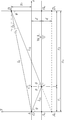
- a water level estimating means for estimating the inundation water level based on an incident angle ⁇ 0 , an antenna incident angle ⁇ 1 of the second lobe, and a distance l 0 from the array antenna to the RF sensor in which measured values are set in advance is provided. It is characterized by that.
- the ground around the RF sensor is flooded water flooded increases, the reflection surface (water surface) is increased, the antenna incident angle phi 1 the reflected wave is incident on the array antenna is changed, this The change is detected as the position of the second lobe in the angular power spectrum.
- the antenna incident angle phi 1 of the second lobe can be estimated from the distance l 0 from the antenna incident angle phi 0 and the array antenna of the main lobe up to RF sensor, a flood water level by simple geometrical calculations ( See equation (30)). This makes it possible for the inundation detection device to detect how much the inundation has occurred.
- a sixth configuration of the inundation detection device is to transmit radio signals at different timings from a plurality of transmitting antennas that are arranged vertically side by side at locations where inundation detection is performed and intermittently transmit radio signals wirelessly.
- a receiving antenna that receives each radio signal and outputs a received signal
- Received signal strength detecting means for detecting the received signal strength I, which is the strength of the received signal output by the receiving antenna, and
- an interference waveform which is a variation of the received signal intensity with respect to the height of each transmitting antenna, is detected from each received signal intensity output by the received signal intensity detecting means, and the amplitude of the interference waveform exceeds a predetermined threshold value. It is characterized in that it is provided with an inundation detection determination means for outputting an inundation detection signal.
- the distance from the water surface to each transmitting antenna will be different when the ground at the inundation detection location is flooded. Therefore, the direct wave of the radio wave signal from each transmitting antenna received by the receiving antenna (the radio wave signal directly reaching the receiving antenna from the transmitting antenna) and the reflected wave (the radio wave signal reflected from the transmitting antenna on the water surface and directly reaching the receiving antenna). Since the phase difference of is different for each transmitting antenna, the strength of each transmitting antenna varies depending on the height of the transmitting antenna.
- the inundation detecting means can detect the occurrence of inundation by detecting this fluctuation as an interference waveform and determining the amplitude of the interference waveform as a threshold value.
- Interference waveform shift amount detecting means for detecting the shift amount of the interference waveform in the height direction of the transmitting antenna at the time t after that with respect to the position of the interference waveform at the exceeded time t0. It is characterized by including a water level estimating means for estimating the inundation water level at the time t based on the shift amount detected by the interference waveform shift amount detecting means.
- the rise and fall of the flooded water surface shortens the distance from the water surface to each transmitting antenna, so that the rise and fall of the water surface is detected as a shift of the interference waveform. Therefore, the inundation water level can be estimated by detecting this shift amount. This makes it possible for the inundation detection device to detect how much the inundation has occurred.
- the first configuration of the inundation detection system according to the present invention includes an RF sensor installed at a location where inundation detection is performed, which intermittently wirelessly transmits a radio wave signal or wirelessly transmits a radio wave signal in response to a question signal.
- the inundation detection device according to any one of claims 1 to 3 is provided, which is separated from the RF sensor and installed at a higher place than the RF sensor.
- the second configuration of the inundation detection system according to the present invention is characterized in that, in the first configuration, the receiving antenna is installed in a direction in which the received signal strength of the electric field component in the horizontal direction is maximized. And.
- the receiving antenna of the inundation detection device mainly receives the polarization component whose electric field is horizontal (S polarization component with respect to the horizontal boundary plane) among the polarization components of the radio wave signal transmitted from the RF sensor.
- the polarization component whose electric field is horizontal S polarization component with respect to the horizontal boundary plane
- the reflection of electromagnetic waves on the water surface has a small P-polarized light component and a large S-polarized light component.
- the relative permittivity of water is about 80 in the frequency region near 1 GHz, and the refractive index with respect to air is about 9, so that the water surface reflection is remarkably large.
- a third configuration of the inundation detection system includes an RF sensor that is installed at a location where inundation detection is performed and intermittently wirelessly transmits a radio wave signal, and is separated from the RF sensor and more than the RF sensor. It is characterized by including the inundation detection device of the fourth or fifth configuration installed in a high place.
- each antenna element of the array antenna is installed in a direction in which the received signal strength of the electric field component in the horizontal direction is maximized. It is characterized by being.
- a fifth configuration of the inundation detection system includes an RF sensor provided with a plurality of transmitting antennas that are arranged vertically side by side at a location where inundation detection is performed and intermittently transmit radio signals wirelessly, and the RF. It is characterized by including an inundation detection device having the sixth or seventh configuration, which is installed at a higher place than the RF sensor at a distance from the sensor.
- the sixth configuration of the inundation detection system according to the present invention is characterized in that, in the fifth configuration, the receiving antenna is installed in a direction in which the received signal strength of the electric field component in the horizontal direction is maximized. And.
- the first configuration of the inundation detection method according to the present invention is an inundation detection method for detecting whether or not the inundation detection location is inundated.
- the radio wave signal transmitted from the RF sensor installed at the inundation detection location is received by the receiving antenna installed at a higher place than the RF sensor.
- a received signal, which is an electric signal, is generated from the radio wave signal,
- the reception signal strength I (t) which is the strength of the received signal
- the dispersal degree D I; [t ⁇ t 1 , t] within a certain time ⁇ t 1 of the received signal strength I (t).
- the normal reception rate R ([t ⁇ t 2 , t]), which is the rate at which the received signal is normally received within a certain time ⁇ t 2 , is detected.
- the degree of dispersion D (I; [t ⁇ t 1 , t]) is equal to or greater than the predetermined threshold value D th1
- the normal reception rate R ([t ⁇ t 2 , t]) is equal to or less than the predetermined threshold value R th. In this case, it is determined that inundation has been detected.
- the second configuration of the inundation detection method according to the present invention is the case where the dispersal degree D (I; [t ⁇ t 1 , t]) becomes a predetermined threshold value D th2 or more in the first configuration.
- D th2 a predetermined threshold value
- it is characterized in that it is determined that the inundation caution level has been reached.
- the RF sensor is not flooded, it is possible to detect that the lower part of the RF sensor is flooded, and it is possible to detect in advance that the RF sensor is approaching flooding. ..
- DI (t) which is an absolute value of I (t- ⁇ t) or I (t) / I (t- ⁇ t)
- the received signal strength variability in a timely Delta] t 3 times N DI which exceeds a predetermined threshold value DI th is, when it exceeds a predetermined threshold value N Dith, reached flooded caution level It is characterized in that it is determined.
- the RF sensor is not flooded, it is possible to detect that the lower part of the RF sensor is flooded, and it is possible to detect in advance that the RF sensor is approaching flooding. ..
- the fourth configuration of the inundation detection method according to the present invention is an inundation detection method for detecting whether or not the inundation detection location is inundated.
- the radio wave signal transmitted from the RF sensor installed at the inundation detection location is received by the array antenna installed at a higher position than the RF sensor.
- a step of calculating the angular power spectrum of the received signal by detecting the received signal of the radio wave signal received by the array antenna while scanning the maximum receiving sensitivity direction ⁇ s of the array antenna.
- the main lobe showing the direct wave of the received signal directly reaching the array antenna from the RF sensor and the reflected wave reaching the array antenna through reflection on the flooded surface from the RF sensor are shown. It is characterized by including a step of detecting the second lobe and outputting a flood detection signal when the second lobe is detected in the angular power spectrum.
- the fourth configuration flooding detection method in the fourth configuration, the case where the main lobe and the second lobe is detected together, the antenna incident angle phi 0 of the main lobe, the first It is characterized by including a step of estimating the inundation water level based on an antenna incident angle of 2 lobes ⁇ 1 and a distance l 0 from the array antenna to the RF sensor for which a measured value is set in advance.
- the sixth configuration of the inundation detection method according to the present invention is an inundation detection method for detecting whether or not the inundation detection location is inundated.
- a step of detecting an interference waveform which is a variation of the received signal intensity with respect to the height of each transmitting antenna, from each of the received signal intensities, and outputting an inundation detection signal when the amplitude of the interference waveform exceeds a predetermined threshold. It is characterized by having.
- the amplitude of the interference waveform when the amplitude of the interference waveform exceeds the predetermined threshold value, the amplitude of the interference waveform sets the predetermined threshold value.
- the RF sensor which is an electromagnetic wave transmitter
- the RF sensor since the RF sensor, which is an electromagnetic wave transmitter, is used as the sensor for detecting the water level, there is no mechanical failure unlike the float switch, and some dirt is attached. Even so, it operates normally, so maintenance costs can be kept low. Further, in order to determine whether or not the RF sensor has been flooded, the degree of dispersion D (I; [t ⁇ t1, t]) of the received signal strength I (t) of the radio wave signal transmitted from the RF sensor and the normality of the radio wave signal are determined.
- the RF sensor can be installed for a long period of time even if the radio signal is interrupted due to the battery exhaustion or failure of the RF sensor. Since it can be clearly distinguished from the case of flooding, it is not determined that the RF sensor has been flooded by mistake, and an erroneous determination is unlikely to occur. On the contrary, when the radio wave signal of the RF sensor is interrupted except when the RF sensor is flooded, it can be determined that some abnormality such as a dead battery has occurred in the RF sensor. Therefore, the RF sensor can be detected from the flood detection device side. It is possible to automatically detect the occurrence of an abnormality.
- the RF sensor is not flooded. Even so, it is possible to detect that the ground around the place where the RF sensor is installed is flooded. Therefore, when the inundation of the ground is detected, the inundation detection device outputs an inundation caution signal, so that it is possible to call attention early when a road inundation or a flood occurs.
- an array antenna is used as the receiving antenna, the angular power spectrum of the received signal from the RF sensor is detected by the azimuth spectrum detecting means, and the generation of the second lobe showing the reflected wave in the angular power spectrum is detected to cause flooding. It is possible to accurately detect the occurrence. This technique also makes it possible to detect how wet the ground around the RF sensor is. It is also possible to estimate the inundation water level around the RF sensor from the position of the second lobe in the angular power spectrum.
- a plurality of transmitting antennas are arranged vertically at the inundation detection point, and an interference waveform, which is a fluctuation of the received signal intensity with respect to the height of each transmitting antenna, is detected from the received signal from each transmitting antenna, and the interference waveform is detected.
- an interference waveform which is a fluctuation of the received signal intensity with respect to the height of each transmitting antenna
- An “RF sensor” (RF (Radio-Frequency) sensor) is a wireless module that periodically transmits a response signal in the radio frequency band.
- Sensor ID refers to an identification code of an RF sensor.
- the “radio response signal” is a radio wave signal transmitted by an RF sensor and refers to a signal including a sensor ID of the RF sensor.
- the “received response signal” means an electric signal generated by performing demodulation processing or decoding processing of a radio wave response signal.
- “Received Signal Strength” (hereinafter referred to as "RSS”) means the strength of the received response signal.
- the “variability of RSS” (hereinafter referred to as "VRSS”) means the absolute value of the time change value of RSS.
- the RSS of the received response signal received at the (n-1) th time is I (n-1), and the RSS of the received response signal received at the nth time is I (.
- the "normal reception rate” refers to the rate at which a reception response signal is normally received within a certain period of time.
- the "flood detection signal” refers to a signal indicating the presence or absence of flood detection of the RF sensor.
- the “flood caution signal” is a signal indicating whether or not the RF sensor has detected that the RF sensor has not been flooded but has been flooded below it.
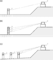
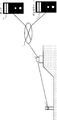
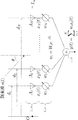
- FIG. 1 is a diagram showing an example of the overall arrangement of the inundation detection system according to the first embodiment of the present invention.
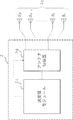
- the inundation detection system of the first embodiment includes an inundation detection device 1 and one or more RF sensors 2.
- the RF sensor 2 is a wireless module that periodically wirelessly transmits a radio response signal having a predetermined signal pattern.
- the RF sensor 2 is shown as an example of a spontaneous transmission type that spontaneously wirelessly transmits a radio wave response signal periodically (at intervals of 1 second).
- the radio wave response signal includes an identification code (hereinafter referred to as “sensor ID”) for identifying the RF sensor 2.
- the RF sensor 2 is a radio wave with respect to a question signal (interrogation signal) periodically transmitted from the inundation detection device 1 like an RF tag (RF tag) used in an RFID system (Radio Frequency IDentification System).
- a passive transmission type that wirelessly transmits a response signal can also be used.
- the inundation detection device 1 is a device that receives the radio wave response signal transmitted from the RF sensor 2 and determines the presence or absence of inundation around the RF sensor 2 from the reception state of the radio wave response signal. The details of the inundation detection device 1 will be described later. As shown in FIG. 1, the inundation detection device 1 is installed at a high place by the RF sensor 2 so as not to be inundated even when the water is increased.
- One RF sensor 2 may be provided for one inundation detection device 1 as shown in FIG. 1A, or one inundation detection device 1 as shown in FIGS. 1B and 1C. It is possible to provide a plurality of RF sensors 2 and arrange them by changing the installation height of each RF sensor 2 or changing the installation location.
- the radio response signal from each RF sensor 2 received by the inundation detection device 1 has a sensor ID included in each radio response signal. By referring to it, it is possible to identify which RF sensor 2 the radio response signal is from.
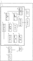
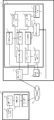
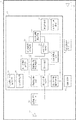
- FIG. 2 is a block diagram showing the configuration of the inundation detection device 1.
- the inundation detection device 1 of this embodiment includes a sensor communication antenna 11, a transmission / reception I / F module 12, a microcomputer 13, an upper communication I / F module 14, an upper communication antenna 15, and an initialization switch 16.
- the sensor communication antenna 11 is an antenna that transmits / receives radio waves to / from the RF sensor 2. For miniaturization, it is preferable to use a flat antenna formed on a printed circuit board or the like.
- the transmission / reception interface module 12 (hereinafter referred to as “transmission / reception I / F module 12”) is a module that performs communication processing with the RF sensor 2 via the sensor communication antenna 11. In this embodiment, as an example of the transmission / reception interface module 12, a communication interface module using spectrum diffusion communication is used in order to secure a long communication distance.
- the transmission / reception I / F module 12 performs demodulation processing and decoding processing from the radio wave response signal received from the RF sensor 2 by the sensor communication antenna 11 to generate a reception response signal.
- the reception response signal includes the sensor ID described above.
- the computer 13 controls the operation of the inundation detection device 1.
- a microcomputer a reconfigurable computer such as a PLD (programmable logic device) or an FPGA (field-programmable gate array), or the like can be used.
- the upper communication interface module 14 (hereinafter referred to as "upper communication I / F module 14") has an inundation detection signal indicating the detection of inundation of the RF sensor and that the RF sensor is not inundated but is inundated below it. It is a module that performs communication to send an inundation caution signal to detect inundation to a higher-level server or a higher-level network such as the Internet.
- a highly versatile communication interface module such as Bluetooth (registered trademark) (IEEE802.15 standard) or Wi-Fi (registered trademark) (IEEE802.11 standard) is used.
- the upper communication antenna 15 is an antenna used for wireless communication when the upper communication I / F module 14 connects to the upper network.
- the initialization switch 16 is a switch for inputting an initialization instruction for setting various threshold values for determining the inundation of the RF sensor or the inundation below the RF sensor by machine learning.
- the computer 13 described above includes a reception signal intensity detection unit 21, a reception intensity dispersion detection unit 22, a dispersion threshold setting unit 23, a normal reception rate detection unit 24, and a normal reception rate threshold setting unit.
- a received signal intensity fluctuation detection unit 26 an intensity fluctuation threshold setting unit 26a, an inundation determination unit 27, an inundation warning determination unit 28, and a determination signal transmission unit 29 are provided.
- Each of these components is a functional module functionally configured inside the computer 13 by causing the computer 13 to read and execute the program.
- the reception signal strength detection unit 21 is a module that detects the reception signal strength (RSS) I (t), which is the strength of the reception response signal output by the transmission / reception I / F module 12, at each time t.
- the received signal intensity detection unit 21 outputs the average value (moving average value) of RSS within a certain time before the time t as I (t). It may be configured.
- the reception intensity dispersion detection unit 22 has a dispersion value ⁇ 2 (I; [t ⁇ t 1 , t] within a fixed time ⁇ t 1 of RSS I (t) detected by the reception signal intensity detection unit 21. ) Is a module that performs processing to detect.
- the variance threshold setting unit 23 machine-learns the mean value ⁇ 2 av0 of the variance value ⁇ 2 (I; [t ⁇ t 1 , t]) of RSS I (t) when the ground is not submerged .
- the normal reception rate detection unit 24 detects the normal reception rate R ([t ⁇ t 2 , t]), which is the rate at which the reception response signal is normally received within a certain time ⁇ t 2 at each time t. It is a module that performs.
- Normal reception rate threshold setting unit 25 ground to machine learning an average value R av0 of normal reception rate when peacetime not flooded R ([t- ⁇ t 2, t]), the average value given to R av0 It is a module that performs a process of setting a value obtained by multiplying a coefficient r R (0 ⁇ r R ⁇ 1) to a threshold value R th1 .
- DI (t) Is a module that performs a process of detecting the received signal intensity fluctuation (VRSS)
- ⁇ t represents the time from the reception time of the previous radio wave response signal to the reception time of the radio wave response signal of this time (time t).
- Intensity variation threshold setting unit 26a VRSS when peacetime the ground is not flooded
- the inundation determination unit 27 outputs a dispersion value ⁇ 2 (I; [t ⁇ t 1 , t]) output by the reception intensity dispersion detection unit 22 with a threshold value ⁇ 2 th1 or more and is output by the normal reception rate detection unit 24.
- This module performs a process of outputting an inundation detection signal when the normal reception rate R ([t ⁇ t 2 , t]) becomes equal to or less than a predetermined threshold value R th1 .
- the inundation warning determination unit 28 is a module that generates and outputs an inundation warning signal indicating whether or not the RF sensor has detected that the RF sensor has not been inundated but has been inundated below it.
- the inundation warning determination unit 28 determines when the dispersion value ⁇ 2 (I; [t ⁇ t 1 , t]) output by the reception intensity dispersion detection unit 22 becomes the threshold value ⁇ 2 th2 or more, or ⁇ t for a certain period of time.
- number N DI which has exceeded the threshold value DI th is, when it exceeds a predetermined threshold value N Dith, outputs a flooded attention signal.
- the determination signal transmission unit 29 is a module that performs a process of transmitting an inundation detection signal output by the inundation determination unit 27 and an inundation warning signal output by the inundation warning determination unit 28 to the upper network through the upper communication I / F module 14. Is.
- dispersion value ⁇ 2 (I (t)) is used as the “spraying degree” of RSS I (t)
- the “spreading degree” is used.
- standard deviation, unbiased variance, mean deviation, data range, etc. can also be used.
- the relationship between the RSS I (t) of the radio wave response signal received by the inundation detection device 1 and the water level level around the RF sensor 2 will be described.
- the water surface exists below the RF sensor 2 when the radio wave response signal is transmitted from the RF sensor 2 to the sensor communication antenna 11 of the inundation detection device 1. Since this is a principle explanation, it is assumed that the water surface is a still water surface with no waves for the sake of easy understanding.
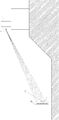
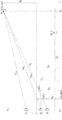
- the propagation path of the radio wave response signal is as shown in FIG. In FIG. 3, assuming that the RF sensor 2 is a transmission point A, the sensor communication antenna 11 is a reception point B, and points A and B are on a still water surface, as shown in FIG.
- a vertical surface including points A and B is provided.
- the coordinates of the transmission point A be (0, y A )
- the coordinates of the reception point B be (x B , y B )
- the electromagnetic wave (radio response signal) emitted from the transmission point A is a spherical wave that spreads radially
- the path of the electromagnetic wave that reaches the reception point B is (1) directly from the transmission point A to the reception point B.
- Path p AB (2) Reflected from transmission point A at reflection point C on the water surface, path p ACB to reception point B, (3) Refraction from transmission point A at refraction point D on water surface into water
- the path p ADECB , etc. which enters , is reflected at the reflection point E on the bottom surface of the water, is refracted at the refraction point C on the water surface, and reaches the reception point B.
- the frequency of the electromagnetic wave currently assumed is the frequency band (900 MHz to a dozen GHz) used in ordinary radio-radio communication such as RFID and Bluetooth (registered trademark). In this frequency band, the relative permittivity of water is about 80, and the refractive index of water is very large, about 8-9.
- the path length l AB of the path p AB, the path length l ACB path p ACB, x-coordinate x C of the reflection point C of the path p ACB, incidence and reflection angle of the reflection point C theta C, and at the receiving point B The angle ⁇ B formed by the paths p AB and p AC B is expressed as follows, respectively.
- the electric field components of the electromagnetic wave incident on the receiving point B through the paths p AB and p ACB are set to E 1 and E 2 , respectively, and the magnetic field components are set to H 1 and H 2 , respectively, and the electric field E is set.
- the p-polarized light components of 1 , E 2 are E 1p , E 2p
- the p-polarized light components of magnetic fields H 1 , H 2 are H 1p , H 2p
- the s polarized light components of electric fields E 1 , E 2 are E 1s , E 2s , magnetic field.
- i 1 and i 2 are unit vectors representing the directions of the electric fields E 1 and E 2 , respectively, i z is a unit vector in the direction perpendicular to the xy plane, ⁇ is the angular frequency of the electromagnetic wave, and ⁇ 12 is. It is the phase shift amount of the electromagnetic wave (E 2 , H 2 ) with respect to the electromagnetic wave (E 1 , H 1 ) at the receiving point B.
- the time average values ⁇ U p > and ⁇ U s > of the energy densities of the p-polarized electromagnetic wave and the s-polarized electromagnetic wave at the receiving point B are expressed as follows, respectively.
- ⁇ U 1p > and ⁇ U 1s > are the p-polarized component of the electromagnetic wave (direct wave) reaching the receiving point B from the transmitting point A through the path p AB, and the time average value of the energy density of the s polarized component.
- ⁇ U 2p > and ⁇ U 2s > are the time average values of the energy densities of the p-polarized component and the s-polarized component of the electromagnetic wave (reflected wave) that reaches the receiving point B from the transmitting point A through the path p ACB .
- phase shift amount ⁇ 12 is expressed as follows.
- the energy density of the electromagnetic wave is attenuated in proportion to 1 / l 2 if the optical path length from the transmission point A is l. Therefore, if the time average values of the energy densities of the p-polarized electromagnetic waves and s-polarized electromagnetic waves emitted from the transmission point A are ⁇ U p0 > and ⁇ U s0 >, then ⁇ U 1p >, ⁇ U 1s >, and ⁇ U 2p > , ⁇ U 2s > are expressed as follows.
- the above consideration is for the case where the water surface is assumed to be a still water surface, but the actual water surface is rippling. Therefore, next, let us consider the water surface with waves.
- the actual water surface has a three-dimensional spread, but here, only in the vertical plane including the transmission point and the reception point (hereinafter referred to as the "reflection plane"), only a simple qualitative evaluation is performed. Let's think about.
- FIG. 7 is a diagram showing a propagation path of an electromagnetic wave in a reflection plane on a water surface having waves.
- the x-axis is set on the horizontal plane including the average water surface (horizontal plane of the average water level), the z-axis is set vertically upward, and the origin O is set on the foot lowered from the transmission point A to the x-axis.
- the electromagnetic wave takes a path ACB that is reflected from the transmitting point A at the reflection point C on the water wave surface and reaches the receiving point B.
- the angle at which the tangent of the water wave surface at the reflection point C forms with the horizontal plane is ⁇
- the angle between the tangent with the path AC and the path CB is ⁇
- the angle at which the normal of the water wave surface at the reflection point C forms with the path AC and the path CB is ⁇ .
- the incident / reflection angle ⁇ is expressed as follows.
- route lengths l AB and l ACB of the route AB and the route ACB are expressed as follows, respectively.
- phase difference ⁇ The position of the electromagnetic wave (reflected wave) w (ACB) from the transmitting point A to the receiving point B through the path ACB with respect to the electromagnetic wave (direct wave) w (AB) passing through the path AB and reaching the receiving point B.
- the phase difference ⁇ is expressed as follows.
- ⁇ is the wavelength of the electromagnetic wave
- ⁇ is each frequency of the electromagnetic wave
- c is the speed of light.
- the reception intensity I B of the electromagnetic waves received at the receiving point B is expressed as follows.
- I AB is the intensity of the direct wave w (AB) at the receiving point B
- I ACB is the intensity of the reflected wave w (ACB) at the receiving point B
- R ( ⁇ ) is the equation (6a) or the equation (6b).
- I 0 represents the intensity of the electromagnetic wave transmitted from the transmission point A
- cos ⁇ represents the direction cosine between the path vector (AB) and the path vector (CB).
- the actual movement of the water wave surface is extremely complicated, but here we simply approximate the water wave surface with a sine wave, where the amplitude of the water wave is h w , the wavelength is ⁇ w , and the angular frequency is ⁇ w .
- the height h C of the point is expressed as follows.
- t is the time
- x C is the x coordinate of the reflection point C
- x C l 0 .
- H B 1.0 m
- water wave amplitude h w 0.1 m
- electromagnetic wave frequency f 2.0 GHz.
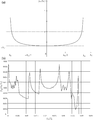
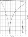
- the number of Monte Carlo calculations was set to 10,000,000. Since the street water wavefront above is approximated by a sine wave, the probability distribution function f hC (h C) of the h C is opposite sinusoidal distribution function as shown in FIG. 8 (a). Then, the probability distribution function f IB (I B) of the reception intensity I B, the probability distribution function f hC (h C) is to have been reflected.
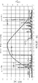
- Figure 9 is a diagram showing the calculation results of the change in the average value ave of the relative received intensity I B / I 0 due to the change in the water level (I B / I 0).
- Figure 10 is a diagram showing the calculation results of the change in the standard deviation of the relative received intensity I B / I 0 due to the change in water level ⁇ (I B / I 0) .
- S waves were used.
- the number of Monte Carlo calculations per water level was set to 200,000.
- the "water level" on the horizontal axis is the height of the average water surface (z coordinate). In FIGS. 9 and 10, when the water level reaches 2.0 m, the average water surface is the height of the transmission point A. reach up to h A.
- the above is a study on the case where one direct wave interferes with one reflected wave at the receiving point.
- the electromagnetic waves emitted from the transmitting point reach the receiving point directly, and a plurality of electromagnetic waves are examined.
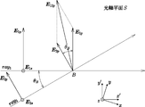
- the case where the reflected wave reflected at the reflection point interferes multiple times at the reception point is also examined. Since the actual water surface has a three-dimensional expanse, general discussions need to be conducted in a three-dimensional space. However, here, for the purpose of conducting a simple qualitative desk study, the reflection and interference of electromagnetic waves in the vertical plane S including the transmitting point and the receiving point will be examined.
- the vectors i 0 , ..., I N are unit vectors in the optical axis plane S and in the direction perpendicular to the optical axis of the electromagnetic waves ray 0 , ray 1 , ..., Ray N , respectively, and i z is the optical axis.
- the unit vectors ⁇ 0 , ..., ⁇ N in the direction perpendicular to the plane S are the phases of the electromagnetic waves ray 0 , ray 1 , ..., Ray N at the point P, respectively.
- the electric and magnetic fields of the interference wave at the point P are as follows.
- the time average ⁇ U (p) > of the electromagnetic field energy U (p) of the P polarization component at the point P is as follows.
- the S-polarized light component can be calculated in the same manner, and the time average ⁇ U (s) > of the electromagnetic field energy U (s) of the S-polarized light component at the point P is as follows.
- the vertical plane S including the transmission point A and the reception point B is called an "optical axis plane" or a "reflection plane”, and reflection / interference in the reflection plane S is considered.
- the x-axis is set in the horizontal direction and the y-axis is set in the vertical direction in the reflection plane S, and the z-axis is set in the direction perpendicular to the reflection plane S. It is assumed that the water surface is translationally symmetric with respect to the z direction.
- the water surface is represented as a water surface curve f w (x, t) that oscillates within the reflection plane S.
- the angle of incidence and the angle of reflection of the electromagnetic wave with respect to the normal of the water surface are equal at the reflection point C according to the law of reflection. That is, the midline between the incident path and the reflection path at the reflection point C is perpendicular to the tangent line of the water surface curve f w (x C , t) at the reflection point C.
- this is referred to as a “reflection condition”.
- the path that is emitted from the transmission point A, satisfies the reflection condition, is reflected on the water surface, and reaches the reception point B is called a "reflection path”.
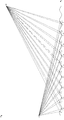
- FIG. 12 shows an example of multiple interference due to reflection on a wavy water surface.
- the reflection points in each reflection path are C 1 , C 2 , ..., C 19 as shown in FIG.
- the paths AC 12 , AC 14 , AC 16 and AC 18 cross the water surface curve f w (x, t), so these reflection paths cannot be taken.
- the condition that "the reflection path does not intersect the water surface curve" is called a "non-crossing condition”.
- the “significant reflection path” is defined.
- h A 5.0 m transmission points A
- height h B 8.0 m of receiving point B
- water wave amplitude h w 0.05 m
- the water level level y w0 is changed in the range of 0.2 to 4.0 m.
- FIG. 14 shows the relationship between the water level (h A -y w 0 ) and the number of effective reflection paths n C.
- Figure 15 shows the relationship between the average value ave of the water level and relative reception intensity (I B / I 0).
- FIGS. 15 and 16 show the relationship between the standard deviation of the water level and relative reception strength ⁇ (I B / I 0) .
- B 5.0 m
- water wave wavelength ⁇ w 1.5 ⁇ 2 ⁇ h w
- electromagnetic wave frequency f 2.4 GHz.
- the "water level" on the horizontal axis is the distance (h A -y w 0 ) from the average water surface to the transmission point A.
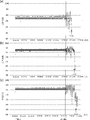
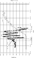
- FIG. 17 shows the results of measuring the change in reception intensity due to the change in the distance between the transmission point A and the water surface by actually using an active beacon in the laboratory.
- the horizontal axis represents time and the vertical axis represents reception intensity (dB).
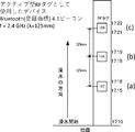
- FIG. 18 is a diagram showing measurement conditions for the measurement of FIG.
- poles are installed in the water tank
- active beacons are installed by changing the height at 125 cm intervals
- the measurement results of (a), (b), and (c) of FIG. 17 represent the reception strength of the signal from the beacon of (a), (b), and (c) of FIG. 18, respectively.
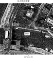
- FIG. 20 is an external photograph of the test system used in the external environment measurement test.
- FIG. 20A is a photograph showing the installation state of the RF sensor 2
- FIG. 20B is a photograph showing the installation state of the radio wave reception measurement system.
- a deck block was installed on the tidal flat, and columns were erected on the shoe blocks, and RF sensors 2 were fixed at three locations with different heights of the columns.
- each RF sensor 2 is a spontaneous transmission type and is set to transmit a radio wave response signal every second.
- the frequency band used for the radio wave response signal was set to 2.4 GHz, and communication was performed by spectral diffusion communication.
- a water depth sensor was installed on the upper surface of the shoe stone block.
- the radio wave reception measurement system was installed on the coastal embankment as shown in FIG. 20 (b).
- the horizontal distance from the shoe stone block to the receiving antenna of the radio wave reception measurement system was 6.6 m
- the vertical distance from the tidal flat ground where the shoe stone block was installed to the receiving antenna was 4.2 m.
- the receiving antenna was installed so that the receiving sensitivity of the radio wave whose electric field oscillates in the horizontal direction was maximized so that the S-polarized light could be received with the highest sensitivity.
- a video camera was installed beside the receiving antenna to take a picture of the surroundings of the RF sensor 2.
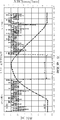
- FIG. 21 is a diagram showing the measurement results of the water level around the RF sensor 2 and RSS in the external environment.
- the result of FIG. 21 is the data measured by the lowest of the three RF sensors 2 of FIG. 20 (a).
- the horizontal axis represents the measurement time (8:00 to 11:00)
- the left vertical axis represents RSS [dB]
- the water level level indicates the value measured at each time t by the water depth sensor. From the video recorded by the video camera, the area around the shoe stone block began to flood at 9:00, and the water surface reached the RF sensor 2 at the bottom at 9:47.
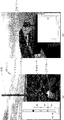
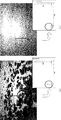
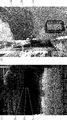
- FIG. 22 shows the inundation state around the RF sensor 2 at each time.
- FIG. 22 (a) shows the inundation situation around the RF sensor 2 at 9:00 time
- FIG. 22 (b) shows the inundation situation around the RF sensor 2 at 9:00 time.
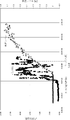
- FIG. 23 is a diagram showing the measurement results of the water level around the RF sensor 2 and the RSS dispersion ⁇ 2 (RSS) in the external environment.
- the measurement data in FIG. 23 is based on the same radio wave response signal as in FIG.
- the horizontal axis is the measurement time (8:00 to 11:00)
- the left vertical axis is the RSS dispersion ⁇ 2 (RSS) [dB]
- the right vertical axis is the water level level [m] (the upper surface of the shoe stone block is 0). Water depth).
- the dispersion ⁇ 2 (RSS) of RSS increases sharply when flooding around the RF sensor 2 begins. It is considered that this is because RSS fluctuation due to water surface wave vibration is added to normal noise.
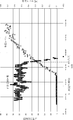
- FIG. 24 is a diagram showing the measurement results of the water level around the RF sensor 2 and the number of normal receptions in the external environment.
- the measurement data in FIG. 24 is based on the same radio wave response signal as in FIG.
- the horizontal axis represents the measurement time (8:00 to 11:00)
- the left vertical axis represents the number of normal receptions [times]
- the right vertical axis represents the water level level [m] (water depth with the upper surface of the shoe stone block as 0).
- the "normal reception count” means the number of times that the reception response signal is normally received within a certain period of time.
- the "normal reception rate” is obtained by dividing the number of normal receptions by the number of times the radio wave response signal is transmitted from the RF sensor 2 within that time.
- FIG. 24 shows the number of times the reception response signal was normally received per 1.5 minutes.
- the number of normal receptions does not change much even if the ground around the RF sensor 2 is flooded. It is considered that this is because the error correction function on the communication protocol in the transmission / reception I / F module 12 corrects the partial error of the received signal due to the interference noise due to some degree of multipath fading.
- the distance between the RF sensor 2 and the water surface is closer than 20 cm, the influence of multipath fading of the radio response signal becomes extremely large, so that the number of normal receptions begins to decrease and the water surface reaches the height of the RF sensor 2. Then, the number of normal receptions decreases sharply. Therefore, it can be seen that the inundation of the RF sensor 2 can be detected by detecting a sudden decrease in the number of normal receptions (or the normal reception rate).
- FIG. 25 is a diagram showing the measurement results of the water level around the RF sensor 2 and the VRSS in the external environment.
- the measurement data in FIG. 25 is based on the same radio wave response signal as in FIG.
- the horizontal axis represents the measurement time (8:00 to 11:00)
- the left vertical axis represents VRSS [dB]
- the right vertical axis represents the water level level [m] (water depth with the upper surface of the shoe stone block as 0).
- VRSS is the absolute value of DI (t)
- the VRSS rapidly increases when the ground around the RF sensor 2 begins to be submerged, and then increases as the distance between the RF sensor 2 and the water surface approaches, and the water surface reaches the height of the RF sensor 2. Then it will increase further. This corresponds to the change in RSS shown in FIG.
- the value of VRSS after the ground around the RF sensor 2 is flooded has a large variation. Therefore, in order to determine the presence or absence of flooding of the ground around the RF sensor 2 from the value of VRSS, it is more constant than simply determining whether or not the value
- the positional relationship between the inundation detection device 1 and each RF sensor 2 is 80.2 m in a horizontal distance, 15.0 m in a vertical distance, and 81.6 m in a straight line distance across a river (measured value). Then, each RF sensor 2 can be seen directly from the inundation detection device 1.
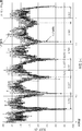
- FIG. 29 shows the measured values of the water level and the time change of RSS with respect to the RF sensor 2a.
- FIG. 30 shows the measured values of the time change of the water level and the number of normal receptions (normal reception count; hereinafter referred to as “NRC”) for the RF sensor 2a.
- FIG. 31 shows the measured values of the water level and the time change of RSS dispersion with respect to the RF sensor 2a.
- the horizontal axis represents time (hours: minutes).
- the vertical axis of FIG. 29 is the water level (left axis) and RSS (right axis)
- the vertical axis of FIG. 30 is the water level (left axis) and NRC (right axis)
- the reference plane (0 m plane) of the water level is set to a height of 0.13 m from the riverbed directly under the RF sensor 2a, and the water level is ⁇ 0. In the state where no inundation occurs (the riverbed directly under the RF sensor 2a has no water). It is 13 m. The height at which the uppermost RF sensor 2a is installed is 2.1 m from the water level reference plane.
- the RSS value in FIG. 29 is a moving average value obtained by averaging sample values measured every 10 seconds over a period of 2 minutes before.
- the RSS variance in FIG. 31 represents the variance of the RSS values sampled during the three minutes before the time at each time.
- the riverbed was submerged from around 8:00, the RF sensor 2a was submerged between 10:00 and 12:10, and around 15:00. It can be seen that the flooding of the riverbed has ended. From the start of flooding of the riverbed to the submergence of the RF sensor 2a (around 8:00 to 10:00), and from the end of the submergence of the RF sensor 2a to the end of the submergence of the riverbed (12: (Around 10-15: 00), there is a water surface around the RF sensor 2a, and the distance between the water surface and the RF sensor 2a changes with time. This section is called the "non-submerge flooding period". Looking at the RSS observation results (FIG.
- the non-flooding period (hereinafter referred to as the “non-flooding period”). .) Cannot be distinguished. It is considered that this is because the error correction function of the receiver in the inundation detection device 1 cancels out the influence of the multipath fading noise caused by the water surface reflection. Therefore, it is difficult to detect the occurrence of flooding just by observing the NRC.
- the RF sensor 2a when the RF sensor 2a is submerged, the RSS becomes 0 as the RSS sharply decreases, and the communication is interrupted. Therefore, it can be seen that by observing the NRC, it is possible to sensitively detect whether or not the RF sensor 2a is submerged.
- the RSS dispersion has a large amplitude with respect to changes in water depth. It changes with. Then, as the water depth increases, the amplitude of the RSS dispersion decreases while vibrating. When the water depth exceeds 1 m, the RSS dispersion becomes almost the same level as the non-flooded period. On the other hand, the RSS dispersion increases sharply in the vicinity immediately before the RF sensor 2a is submerged and in the vicinity immediately after the submersion is completed. Therefore, by observing the rapid increase in RSS dispersion, it is possible to detect that the ground around the RF sensor 2a is submerged or that the RF sensor 2a is about to be submerged.
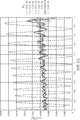
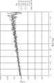
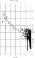
- FIG. 32 is a diagram in which the measured values of the water level at each time shown in FIG. 29 and the measured values of RSS for the RF sensor 2a are plotted with the horizontal axis representing the water level and the vertical axis representing RSS.
- the phasor of the received signal s received by the receiving antenna at the point B is as shown in the following equation (20a).
- k, ⁇ , and f are the wave number, wavelength, and frequency of the radiated radio wave
- c is the light velocity
- s 0 is the reception intensity of the direct wave
- ⁇ is the optical path difference ⁇ l at the point C
- the reflectance R on the water surface ( ⁇ ) the incident angle of the direct wave and the reflected wave to the receiving antenna ⁇ 0 , ⁇ 1, and the reflected wave attenuation coefficient smaller than 1 determined by the directivity function g ( ⁇ ) of the receiving antenna.
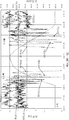
- FIG. 34 is a diagram showing actual measurement values of the water level and the time change of RSS with respect to the RF sensors 2a, 2b, and 2c.
- the measurement data shown in FIG. 34 was measured on a day different from the measurement date of the data shown in FIGS. 29-31.
- the RSS of the uppermost RF sensor 2a is substantially in phase with the RSS of the lowermost RF sensor 2c as the water level rises or falls. It is vibrating. Further, the RSS of the RF sensor 2b in the central portion vibrates in substantially the opposite phase to the RSS of the RF sensors 2a and 2c as the water level rises or falls.
- Period DerutaLv vibration of RSS for level changes, from FIG. 32, since it is ⁇ Lv ⁇ 33cm, a d ab / ⁇ Lv ⁇ 1.5,d ac / ⁇ Lv ⁇ 2.0, d ab / ⁇ Lv almost half integer , D ac / ⁇ Lv is almost an integer.
- FIG. 34 shows the measurement result of FIG. 34.
- the water level changes by simultaneously measuring RSS for two RF sensors 2a, 2b (or 2b, 2c) installed at intervals that are half-integer times ⁇ Lv and taking the ratio (difference in dB value). It is possible to detect RSS vibrations with high sensitivity in real time.
- FIG. 35 shows the time change of the ratio RSS (2a) / RSS (2b) of RSS to the two RF sensors 2a and 2b.
- the dispersion value ⁇ 2 (I; [t ⁇ t 1 , 1 ,) within the constant time ⁇ t 1 of the received signal strength I (t) of the radio wave response signal from the RF sensor 2 The inundation of the RF sensor 2 is detected by the threshold determination of the normal reception rate R ([t ⁇ t 2 , t]) within ⁇ t 2 for a certain period of time and t]).
- the ground around the RF sensor 2 is submerged. Is detected. Therefore, it is necessary to set the threshold value at the time of determining these threshold values to an appropriate value.
- the received signal strength I (t) the received signal strength I (t), its dispersion value ⁇ 2 (I; [t- ⁇ t 1 , t]), the normal reception rate R ([t- ⁇ t 2 , t]), etc. are flooded with the RF sensor 2. It is considered that the change depends on the surrounding environment in which the detection device 1 is installed.
- the reception signal strength I (t), the dispersion value ⁇ 2 (I; [t ⁇ t 1 , t]), and the normal reception rate R (in normal times when the ground is not submerged) [T- ⁇ t 2 , t]) and the like are sampled, and each threshold value is set by adapting to the surrounding environment by machine learning.
- the user When setting each threshold value, the user inputs an initialization instruction to the inundation detection device 1 by the initialization switch 16 in normal times when the ground is not submerged.
- the dispersion threshold setting unit 23 samples the reception response signal of the radio response signal periodically transmitted from the RF sensor 2 for a certain period of time, and the ground is not submerged in normal times.
- variance sigma 2 of RSS I if (t); the average value sigma 2 av0 of (I [t- ⁇ t 1, t]) and machine learning, a predetermined coefficient to the average value ⁇ 2 av0 r ⁇ (r ⁇ > The value multiplied by 1) is set to the threshold ⁇ 2 th1 .
- the coefficient r ⁇ is a constant that is appropriately set in advance by an experiment.
- the normal reception rate threshold setting unit 25 machine-learns the average value R av0 of the normal reception rate R ([t ⁇ t 2 , t]) in the normal time when the ground is not submerged, and sets the average value R av0 .
- the value obtained by multiplying the predetermined coefficient r R (0 ⁇ r R ⁇ 1) is set to the threshold value R th1 .
- the coefficient r R is a constant that is appropriately set in advance by an experiment.
- the intensity fluctuation threshold setting unit 26a machine-learns the average value
- the value multiplied by DI (r DI > 1) is set to the threshold value DI th .
- the coefficient r DI is a constant that is appropriately set in advance by an experiment.
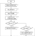
- FIG. 36 is a flowchart showing the detection operation of the presence / absence of inundation / flooding of the inundation detection device 1.
- the transmission / reception I / F module 12 demodulates / decodes the radio wave response signal and outputs the reception response signal (S1). ..
- the received signal strength detection unit 21 detects and outputs RSS I (t n ) at time t n . Further, the received signal strength fluctuation detection unit 26 calculates and outputs VRSS
- the sampling time ⁇ t 1 for the variance calculation is a preset constant value.
- normal reception rate detection unit 24 at time t n, the time t n normal reception which is a ratio of the received response signal is received successfully within a certain time Delta] t 2 before the R ([t n - ⁇ t 2 , t n ]) is calculated and output (S4).
- the sampling time ⁇ t 2 for calculating the normal reception rate is a preset constant value.
- the inundation determination unit 27 detects the normal reception rate when the dispersion value ⁇ 2 (I; [t n ⁇ ⁇ t 1 , t n ]) output by the reception intensity dispersion detection unit 22 is the threshold value ⁇ 2 th1 or more. It is determined whether or not the normal reception rate R ([t n ⁇ t 2 , t n ]) output by the unit 24 is equal to or less than the predetermined threshold value R th1 (S5).
- the determination condition when the " ⁇ 2 (I [t n - ⁇ t 1, t n]) ⁇ ⁇ 2 th1 ⁇ R ([t n - ⁇ t 2, t n]) ⁇ R th1 " is satisfied,
- the inundation determination unit 27 outputs an inundation detection signal, and the upper communication I / F module 14 transmits the inundation detection signal to the upper network via the upper communication antenna 15 (S6).
- step S5 the determination condition " ⁇ 2 (I; [t n - ⁇ t 1, t n])> ⁇ 2 th1 ⁇ R ([t n - ⁇ t 2, t n]) ⁇ R th1 " is satisfied If not, the inundation warning determination unit 28 determines whether or not any of the following submersion determination conditions is satisfied (S7).
- the reception intensity scatter degree detecting unit 22 outputs the variance value ⁇ 2 (I; [t- ⁇ t 1, t]) ⁇ relative to the threshold ⁇ 2 th2 2 (I; [ t- ⁇ t 1, t]) ⁇ ⁇ 2 th2 .
- steps S1 to S8 are repeatedly executed.
- the RF sensor 2 installed around the inundation detection device 1 causes inundation. You can know what happened.
- the management server receives the inundation warning signal transmitted from the inundation detection device 1, it can know that the ground has been flooded in the vicinity of the RF sensor 2 installed around the inundation detection device 1. In this way, the inundation detection system of the present embodiment can accurately detect the inundation or flooding condition around the RF sensor 2.
- FIG. 37 is a diagram showing the overall arrangement of the inundation detection system according to the second embodiment of the present invention.
- the inundation detection system according to the second embodiment includes an inundation detection device 1', an RF sensor 2, and a management server 42, and the inundation detection device 1'and the management server 42 are connected via a communication line 41. ing. It is assumed that the inundation detection device 1'is connected to the communication line 41 either by wire or wirelessly. Further, it is assumed that the management server 42 is connected to the related organization server 43 installed in the local government or other disaster prevention related organizations via the communication line 41.
- the RF sensor 2 is the same as in the first embodiment, and the inundation detection device 1'performs wireless communication with the RF sensor 2 in the same manner as in the first embodiment. Further, the number of RF sensors 2 may have various configurations as in FIG. 1 of the first embodiment.
- FIG. 38 is a block diagram showing the functional configurations of the inundation detection device 1'and the management server 42 of FIG. 37.
- the communication I / F module 51 in the management server 42 is a module that performs processing for the management server 42 to communicate with the communication line 41.
- the transmission / reception I / F module 12 performs demodulation processing and decoding processing from the received radio wave response signal to generate a reception response signal. .. Then, the host communication I / F module 14 transmits the generated reception response signal to the management server 42 via the communication line 41.
- the upper communication I / F module 14 accumulates the reception response signal at regular time intervals (for example, every 10 seconds) and compresses the accumulated reception response signal. May be sent to the management server 42.
- the management server 42 When the management server 42 receives the reception response signal from the inundation detection device 1', the management server 42 performs the same determination processing as in the first embodiment based on the reception response signal. Then, when the inundation warning signal is output by the inundation warning determination unit 28 or the inundation detection signal is output by the inundation determination unit 27, the determination signal transmission unit 29 transmits the inundation warning signal or the inundation detection signal. , Transmit to the related organization server 43 via the communication line 41.
- the management server 42 can collectively perform determination processing regarding flooding and inundation for a plurality of inundation detection devices 1'.
- time-series reception response signals sent from a large number of inundation detection devices 1' are stored in the management server 42, and machine learning is performed based on the accumulated time-series reception response signals.
- FIG. 39 is a diagram showing an example of an overall layout of the inundation detection system according to the third embodiment of the present invention.
- the basic arrangement is the same as that of the first embodiment, but the present embodiment is different from the first embodiment in that the inundation detection device 1 includes the array antenna 11a as the sensor communication antenna.
- FIG. 40 is a block diagram showing the configuration of the inundation detection device 1 of FIG. 39.
- the same components as those in FIG. 2 of the first embodiment are designated by the same reference numerals.
- the inundation detection device 1 of the present embodiment includes an array antenna 11a in which a plurality of antenna elements are arranged in an array as a sensor communication antenna.
- Each antenna element of the array antenna 11a is vertically arranged in columns at regular intervals. Further, each antenna element of the array antenna 11a is provided with a phase shifter 11b in a one-to-one correspondence, and is provided with an adder 11c for adding the outputs received by each phase shifter 11b. Further, as a functional module of the computer 13, a weight setting unit 30, a directional spectrum detection unit 31, a water level estimation unit 32, and a water level signal transmission unit 33 are provided.
- the weight setting unit 30 is a module that performs a process of setting the weight (phase shift amount and gain) of each phase shifter 11b.
- the azimuth spectrum detection unit 31 is a module that calculates a spectrum of reception intensity with respect to the reception direction (hereinafter referred to as “angular power spectrum” (APS)) based on the reception output of the array antenna.
- the water level estimation unit 32 is a module that performs processing for estimating the presence or absence of precipitation and the flooded water level based on the APS output from the directional spectrum detection unit 31.
- the water level signal transmission unit 33 is a module that performs communication for transmitting the presence or absence of rainfall and the flooded water level output by the water level estimation unit 32 by the upper communication I / F module 14 to a higher network such as a higher server or the Internet.
- Array antenna 11a is, as shown in FIG. 41, the antenna elements A 1, A 2 N (N is an integer of 2 or more), ..., A N are arranged on the vertical straight line L a.
- k and ⁇ are the wave number and wavelength of the incoming wave. Therefore, the received signal x i (t) can be obtained if the directivity of the antenna element A i is g ( ⁇ ).
- the received signal x i (t) of the antenna element A i is phase-shifted and amplified by the phase shifter 11b.
- the weight setting unit 30 sets the phase shift amount ⁇ i of the phase shifter 11b for each antenna element as follows. To set.
- the apex angle ⁇ s is called a steering angle.
- Azimuth spectrum detection unit 31 a steering angle theta s scan range by weighting unit 30 [ ⁇ min, ⁇ max] in (-90 ° ⁇ min ⁇ max ⁇ 90 °) are changed in each steering angle theta s
- the APS can be measured by detecting the reception intensity
- noise internal noise inside the antenna element and external noise outside the antenna element
- APS is calculated by performing statistical processing from a large number of sample values of reception intensity.
- Non-Patent Document 1 APS is measured using these methods.
- the azimuth spectrum detection unit 31 calculates APS P CP ( ⁇ ) by the following statistical calculation.
- Etinctian conjugate represents the expected value (ensemble average)
- T represents transpose
- H represents Hermitian conjugate
- the vector x (t) is called an input vector
- the vector a ( ⁇ ) is called an array response vector
- the matrix Rxx is called an input correlation matrix.
- the directional spectrum detection unit 31 calculates the APS PLP ( ⁇ ) by the following statistical calculation.
- the vector w LP is called the optimal weight vector.
- the azimuth spectrum detection unit 31 calculates APS PMU ( ⁇ ) by the following statistical calculation.
- theta i is the angle of incidence of the incoming waves
- L is the number of incoming waves
- vector e i is the eigenvector of the input correlation matrix A xx
- N is element number (antenna elements eigenvalues and eigenvectors of the input correlation matrix A xx Number).
- the matrix A is called a directional matrix.
- various known methods can be used.
- the water level estimation unit 32 detects and estimates the flooding of the ground due to rainfall and the water level thereof based on the APS thus obtained. For example, as shown in FIG. 33, a direct wave from the RF sensor 2 at the transmission point A passing through the optical path AB and arriving at the array antenna 11a at the reception point B, and a direct wave from the RF sensor 2 at the transmission point A through the optical path ACB and at the reception point B.
- a direct wave from the RF sensor 2 at the transmission point A passing through the optical path AB and arriving at the array antenna 11a at the reception point B and a direct wave from the RF sensor 2 at the transmission point A through the optical path ACB and at the reception point B.
- ⁇ 0 the angle formed by the optical path CB with the horizontal axis (x-axis) is ⁇ 1 .
- FIG. 42 shows an example of APS of radio waves obtained by the array antenna 11a under this condition.
- the APS as shown in FIG. 42A is obtained.
- the APS as shown in FIG. 42B is obtained.
- l 0 is the distance from the transmission point A to the reception point B as shown in FIG. 33, which is measured in advance and preset in the water level estimation unit 32.
- the water level signal transmission unit 33 transmits the water level d detected by the water level estimation unit 32 to the upper server, the Internet, etc. by the upper communication I / F module 14. Send to the upper network.
- the inundation warning determination unit 28 defines the water level d detected by the water level estimation unit 32 as the distance from the water surface to the RF sensor 2 when the water level d satisfies a predetermined condition set in advance (in this case, the water level d is defined by the distance from the water surface to the RF sensor 2. Therefore, the inundation caution signal is also output even when the water level d is equal to or less than a preset predetermined threshold value d min or less (see FIG. 33).
- the inundation detection device 1 serves as a sensor communication antenna with an array antenna 11a, a phase shifter 11b, an adder 11c, a weight setting unit 30, an azimuth spectrum detection unit 31, and a water level estimation.
- the unit 32 is provided, and the array antenna 11a is used to detect the APS of the received radio wave by scanning the steering angle. Then, from the presence or absence of the detected second lobe Lobe 1 of the APS, it is possible to detect the state of the ground being wet due to the occurrence of flooding of the ground or rainfall.
- the incident angles ⁇ 0 and ⁇ 1 of the main lobe Lobe 0 and the second lobe Lobe 1 are detected, and the submerged water level of the flooded ground can be detected by these two incident angles ⁇ 0 and ⁇ 1 .
- FIG. 43 is a diagram showing an example of an overall layout of the inundation detection system according to the fourth embodiment of the present invention.
- the basic arrangement is the same as that of the first embodiment, but the present embodiment is different from the first embodiment in that the array RF sensor 2a is provided as the RF sensor 2.
- the array RF sensor 2a is an array of a plurality of RF sensors 2 in the vertical direction.
- FIG. 43 shows the array RF sensor 2a in which a plurality of RF sensors 2 are linearly arranged on one substrate 2b to form an integrated assembly, the array RF sensor 2a is shown.
- the substrate 2b may be omitted, or a plurality of RF sensors 2 may be arranged and fixedly arranged vertically on the surface of a ground structure such as a pole to which the RF sensor 2 is attached.
- the number of RF sensors 2 constituting the array RF sensor 2a can be any number as long as it is two or more, but it should be a sufficient number so that the shape profile of RSS vibration with respect to a change in water level level can be detected. Is preferable.
- the array length of the RF sensor 2 of the array RF sensor 2a can be set to an arbitrary length, but is defined by the equation (21) from the viewpoint of accurately detecting the shape profile of the RSS vibration with respect to the change in the water level. It is preferable that the length is longer than 1/2 of the vibration period ⁇ of the RSS with respect to the change in the water level. Further, it is more preferable that the length is longer than the vibration period ⁇ of RSS.
- FIG. 44 is a block diagram showing the configuration of the inundation detection device 1 of FIG. 43.
- the same components as those in FIG. 2 of the first embodiment are designated by the same reference numerals.
- the inundation detection device 1 of the present embodiment is different in that the interference waveform detection unit 35, the interference waveform shift amount detection unit 36, the water level estimation unit 32, and the water level signal transmission unit 33 are newly provided. doing.
- the interference waveform detection unit 35 is a module that detects an intensity fluctuation waveform due to interference between a direct wave and a reflected wave from a received signal of a radio wave transmitted from each RF sensor 2 of the array RF sensor 2a.
- the interference waveform shift amount detection unit 36 is a module that performs processing for detecting the shift amount of the intensity fluctuation waveform detected by the interference waveform detection unit 35.
- the water level estimation unit 32 is a module that calculates an estimated value of the submerged water level from the shift amount of the intensity fluctuation waveform detected by the interference waveform shift amount detection unit 36.
- the water level signal transmission unit 33 is a module that performs communication for transmitting the submerged water level calculated by the water level estimation unit 32 by the upper communication I / F module 14 to a higher network such as a higher server or the Internet.
- the RF sensor S i of the array RF sensor 2a rather than sending radio waves at the same time, performs radio transmission at different timings, each in a timely band [Delta] T. This is to prevent the transmitted waves from each RF sensor S i from interfering with each other.
- the length ⁇ T of the time band can be arbitrarily set as long as the length does not cause a large change in the water level within the period of the time band ⁇ T.
- the time band [Delta] T is the degree to which the transmission waves of the RF sensor S i does not interfere, as short as possible is preferable. Specifically, ⁇ T can be several seconds to several tens of seconds.
- Flooding detection device 1, in a time band [Delta] T when receiving radio waves from the RF sensor S i of the array RF sensor 2a, the received-strength detecting unit 21 detects the intensity P i of the received signal.
- Figure 45 is a diagram showing the positional relationship between each RF sensor S i and the sensor communication antenna 11 of the array RF sensor 2a.
- h i is the height of the RF sensor S i.
- the received signal strength s i and the received signal power Pi are as follows.
- FIG. 46 shows an example of the relationship with the strength of the received signal from the RF sensor installed at each height with respect to each water level d w .
- the horizontal axis h represents the height [m] of each RF sensor
- the vertical axis represents the received signal power P [dB].
- RF sensor S i is installed in a plurality of height h i, signals from the RF sensor S i in one time within the band ⁇ T is received.
- the intensities of these signals received within one time band ⁇ T are connected by a line, they oscillate periodically as shown in FIG. It becomes a curve.
- the straight line marked “No water surface” in FIG. 46 is obtained. Therefore, the interference wave detector 35 at each time the band [Delta] T, when the signal from the RF sensor S i is fluctuating curve as shown in FIG. 46, the ground surrounding the array RF sensor 2a is Judged as flooded. Further, when the signal from the RF sensor S i is as straight and reference character "no water” in FIG. 46, the ground surrounding the array RF sensor 2a can be determined not to be flooded.
- the fluctuation curve as shown in FIG. 46 is observed.
- the interference waveform shift amount detection unit 36 continuously detects the shift amount of the vibration waveform from the time when the interference waveform detection unit 35 determines that the ground around the array RF sensor 2a is submerged, thereby causing the submerged water level.
- the water level estimation unit 32 converts this shift amount into the submerged water level dw , and the water level signal transmission unit 33 uses the water level estimation unit 32.
- the detected water level d is transmitted to a higher-level server or a higher-level network such as the Internet by the upper-level communication I / F module 14.
- flooding warning determining unit 28 even if the flood water level d w detected by the water level estimation unit 32 exceeds a predetermined threshold value set in advance, and outputs a flooded attention signal.
- the inundation detection system of the present embodiment includes an array RF sensor 2a in which a plurality of RF sensors 2 are arranged in an array in the vertical direction, and each of the array RF sensors 2a is provided for each fixed time band ⁇ T.
- the ground around the array RF sensor 2a is formed. It can detect whether it is flooded or the ground is wet.
- the water level d w can be detected.
- FIG. 43 shows a configuration example in which a plurality of RF sensors 2 are arranged as the array RF sensor 2a
- the configuration of the array RF sensor 2a includes a plurality of antenna elements 2e for one RF sensor 2.
- the antenna elements 2e may be connected and arranged in an array.
- FIG. 47 shows an example of an array RF sensor 2a in which antenna elements 2e arranged in an array are connected to one RF sensor 2.
- the RF sensor 2 includes a transmission / reception module including a circuit for transmitting a radio wave signal to the inundation detection device 1, and an antenna switch 2d that selects and switches the antenna element 2e used for transmitting the radio wave signal.
- the antenna switch 2d is connected to each of the N antenna elements 2e, and switches the antenna elements 2e connected to the transmission / reception module 2c.
- the transmission / reception module 2c can reliably transmit radio signals within each time band ⁇ T by shifting the timing from each antenna element 2e.
Landscapes
- Physics & Mathematics (AREA)
- General Physics & Mathematics (AREA)
- Engineering & Computer Science (AREA)
- Radar, Positioning & Navigation (AREA)
- Remote Sensing (AREA)
- Electromagnetism (AREA)
- Life Sciences & Earth Sciences (AREA)
- Environmental & Geological Engineering (AREA)
- Fluid Mechanics (AREA)
- Thermal Sciences (AREA)
- Emergency Management (AREA)
- General Life Sciences & Earth Sciences (AREA)
- Geology (AREA)
- Business, Economics & Management (AREA)
- Hydrology & Water Resources (AREA)
- Computer Networks & Wireless Communication (AREA)
- Atmospheric Sciences (AREA)
- Biodiversity & Conservation Biology (AREA)
- Ecology (AREA)
- Environmental Sciences (AREA)
- Examining Or Testing Airtightness (AREA)
- Measurement Of Levels Of Liquids Or Fluent Solid Materials (AREA)
- Emergency Alarm Devices (AREA)
Abstract
Description
各時刻tにおいて、前記受信アンテナより出力される前記受信信号の強度である受信信号強度I(t)を検出する受信信号強度検出手段と、
各時刻tにおいて、前記受信信号強度検出手段が検出する前記受信信号強度I(t)の一定時間Δt1内の散布度D(I;[t-Δt1,t])を検出する受信信号強度散布度検出手段と、
各時刻tにおいて、一定の時間Δt2内に前記受信信号が正常に受信された割合である正常受信率R([t-Δt2,t])を検出する正常受信率検出手段と、
前記受信信号強度散布度検出手段が出力する前記散布度D(I;[t-Δt1,t])が所定の閾値Dth1以上で、且つ前記正常受信率検出手段が出力する前記正常受信率R([t-Δt2,t])が所定の閾値Rth1以下となった場合に、浸水検出信号を出力する浸水検出判定手段と、を備えたことを特徴とする。
一定の時間Δt3内に前記受信信号強度変動度|DI(t)|が所定の閾値DIthを超えた回数NDIが、所定の閾値NDIthを超えた場合に、浸水注意信号を出力する浸水注意報判定手段を備えたことを特徴とする。
前記アレイアンテナにより受信される前記電波信号から、受信信号を生成する受信手段と、
前記受信器により出力される前記受信信号の強度である受信信号強度Iを検出する受信信号強度検出手段と、
前記アレイアンテナの各移相器の移相量を制御して前記アレイアンテナの最大受信感度方向θsを制御するとともに、各最大受信感度方向θsにおける前記受信強度検出手段が出力する受信強度信号I(θs)を取得し、これらの受信強度信号I(θs)から、前記受信信号の角度電力スペクトルを算出する方位スペクトル検出手段と、
前記角度電力スペクトルにおいて、前記受信信号のうち前記RFセンサから前記アレイアンテナに直接到達する直接波を示すメインローブと、前記RFセンサから浸水面での反射の経て前記アレイアンテナに達する反射波を示す第2ローブとを検出し、前記角度電力スペクトルにおける前記第2ローブが検出された場合には、浸水検出信号を出力する浸水検出判定手段と、を備えたことを特徴とする。
前記受信アンテナにより出力される前記受信信号の強度である受信信号強度Iを検出する受信信号強度検出手段と、
前記受信信号強度検出手段が出力する前記各受信信号強度から、前記各送信アンテナの高さに対する受信信号強度の変動である干渉波形を検出し、該干渉波形の振幅が所定の閾値を超えた場合に浸水検出信号を出力する浸水検出判定手段と、を備えたことを特徴とする。
前記干渉波形シフト量検出手段が検出するシフト量に基づき、前記時刻tにおける浸水水位を推定する水位推定手段と、を備えたことを特徴とする。
前記RFセンサから離隔して、前記RFセンサよりも高所に設置された請求項1乃至3の何れか一に記載の浸水検出装置と、を備えたことを特徴とする。
前記浸水検出箇所に設置されたRFセンサから送信される電波信号を、前記RFセンサよりも高所に設置された受信アンテナにより受信し、
前記電波信号から電気信号である受信信号を生成し、
各時刻に於いて、前記受信信号の強度である受信信号強度I(t)、該受信信号強度I(t)の一定時間Δt1内の散布度D(I;[t-Δt1,t])、及び一定の時間Δt2内に前記受信信号が正常に受信された割合である正常受信率R([t-Δt2,t])を検出し、
前記散布度D(I;[t-Δt1,t])が所定の閾値Dth1以上で、且つ前記正常受信率R([t-Δt2,t])が所定の閾値Rth以下となった場合に、浸水が検出されたと判定することを特徴とする。
一定の時間Δt3内に前記受信信号強度変動度|DI(t)|が所定の閾値DIthを超えた回数NDIが、所定の閾値NDIthを超えた場合に、浸水注意レベルに達したと判定することを特徴とする。
前記浸水検出箇所に設置されたRFセンサから送信される電波信号を、前記RFセンサよりも高所に設置されたアレイアンテナにより受信し、
前記アレイアンテナの最大受信感度方向θsを走査しながら前記アレイアンテナにより受信される前記電波信号の受信信号を検出することにより、前記受信信号の角度電力スペクトルを算出するステップと、
前記角度電力スペクトルにおいて、前記受信信号のうち前記RFセンサから前記アレイアンテナに直接到達する直接波を示すメインローブと、前記RFセンサから浸水面での反射の経て前記アレイアンテナに達する反射波を示す第2ローブとを検出し、前記角度電力スペクトルにおける前記第2ローブが検出された場合には、浸水検出信号を出力するステップと、を備えたことを特徴とする。
浸水検出を行う箇所に鉛直方向に並べて配列された、間歇的に電波信号を無線発信する複数の送信アンテナからタイミングをずらせて送信される、前記各電波信号を受信して受信信号を生成するステップと、
前記各受信信号強度から、前記各送信アンテナの高さに対する受信信号強度の変動である干渉波形を検出し、該干渉波形の振幅が所定の閾値を超えた場合に浸水検出信号を出力するステップと、を備えたことを特徴とする。
前記シフト量に基づき、前記時刻tにおける浸水水位を推定するステップと、を備えたことを特徴とする。
「RFセンサ」(RF (Radio-Frequency) sensor)とは、定期的に電波周波数帯域の応答信号を発信する無線モジュールをいう。「センサID」(Sensor ID)とは、RFセンサの識別符号をいう。「電波応答信号」(radio response signal)とは、RFセンサが発信する電波信号であって、そのRFセンサのセンサIDを含む信号をいう。「受信応答信号」(received response signal)とは、電波応答信号を復調処理や復号処理を行うことにより生成される電気信号をいう。「受信信号強度」(Received Signal Strength:以下「RSS」という。)とは、受信応答信号の強度をいう。「受信信号強度変動度」(variability of RSS:以下「VRSS」という。)とは、RSSの時間変化値の絶対値をいう。ここで、RSSの時間変化値の定義については、(n-1)回目に受信された受信応答信号のRSSをI(n-1)、n回目に受信された受信応答信号のRSSをI(n)とすると、n回目の時間変化値DI(n)は、DI(n)=I(n)-I(n-1)として定義してもよいし、DI(n)=I(n)/I(n-1)として定義してもよい。後者の定義は、RSSの値を対数(デシベル)で取り扱う場合に使用される。「正常受信率」(normal reception rate)とは、一定の時間内に受信応答信号が正常に受信された割合をいう。「浸水検出信号」(flood detection signal)とは、RFセンサの浸水の検出の有無を表す信号をいう。「浸水注意信号」(flood caution signal)とは、RFセンサが浸水はしていないがその下方が浸水したことの検出の有無を表す信号をいう。
図1は、本発明の実施例1に係る浸水検出システムの全体配置の一例を示す図である。本実施例1の浸水検出システムは、浸水検出装置1と一乃至複数のRFセンサ2とを備えている。
図2は、浸水検出装置1の構成を示すブロック図である。本実施例の浸水検出装置1は、センサ通信アンテナ11、送受信I/Fモジュール12、マイコン13、上位通信I/Fモジュール14、上位通信アンテナ15、及び初期化スイッチ16を備えている。
次に、本実施例の浸水検出システムに於いて、RFセンサの浸水や、RFセンサが浸水はしていないがその下方が浸水したことの検出を行う原理について説明する。


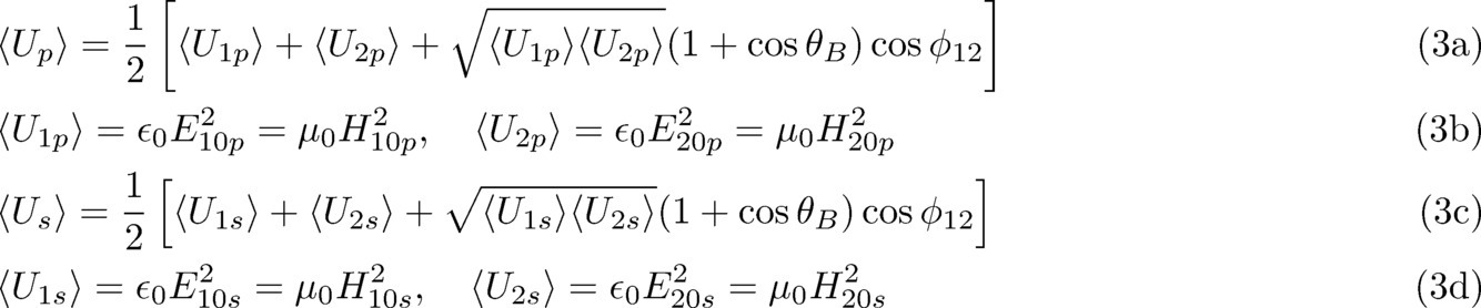


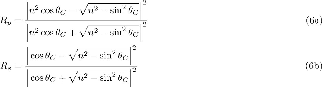
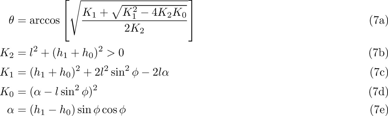
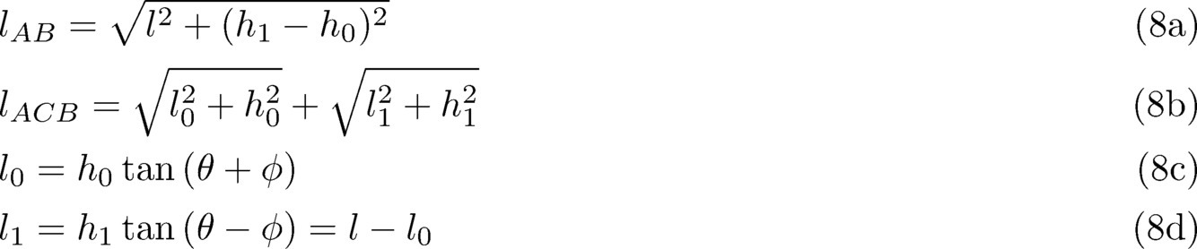

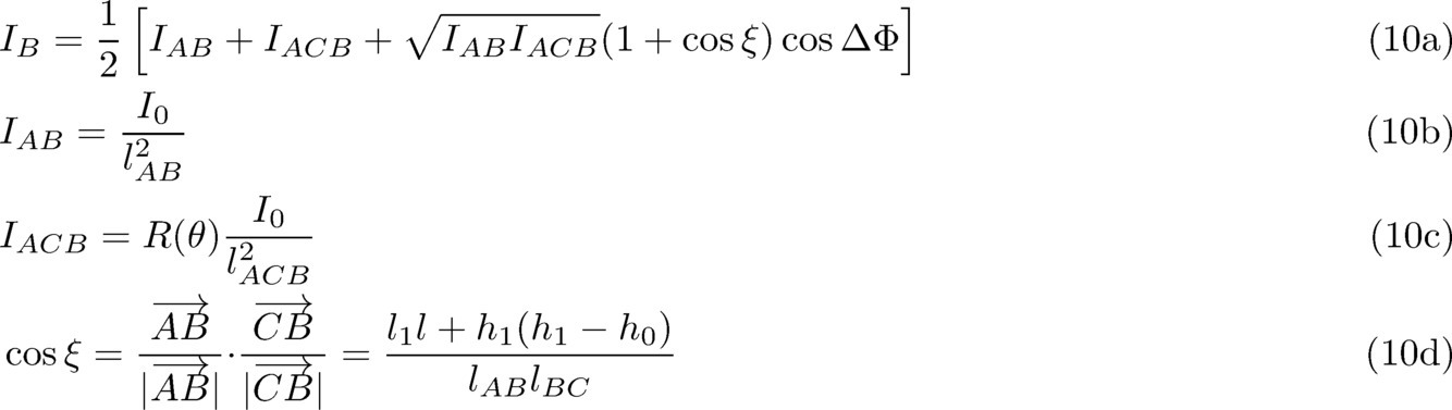



(i)まず、ξを区間[0,2π)の一様乱数で発生させて(hC,φ)を決定する。
(ii)次に、発生させた(hC,φ)から、式(7a)により入射・反射角θを決定する。
(iii)次に、(φ,θ)から、式(8b)により反射経路長lACBを決定する。
(iv)次に、lACBから、式(9a)により位相差ΔΦを決定する。
(v)最後に、(lACB,ΔΦ)から、式(10a)により電磁波の受信強度IBを決定する。
という一連の処理を繰り返し実行し、電磁波の受信強度IBの分布をモンテカルロ法により計算する。尚、この計算に於いては、異なる2つ以上の経路の反射波が同時に干渉する場合については、発生確率が小さいであろうと仮定して考慮していない。
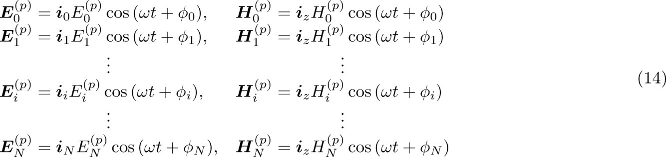
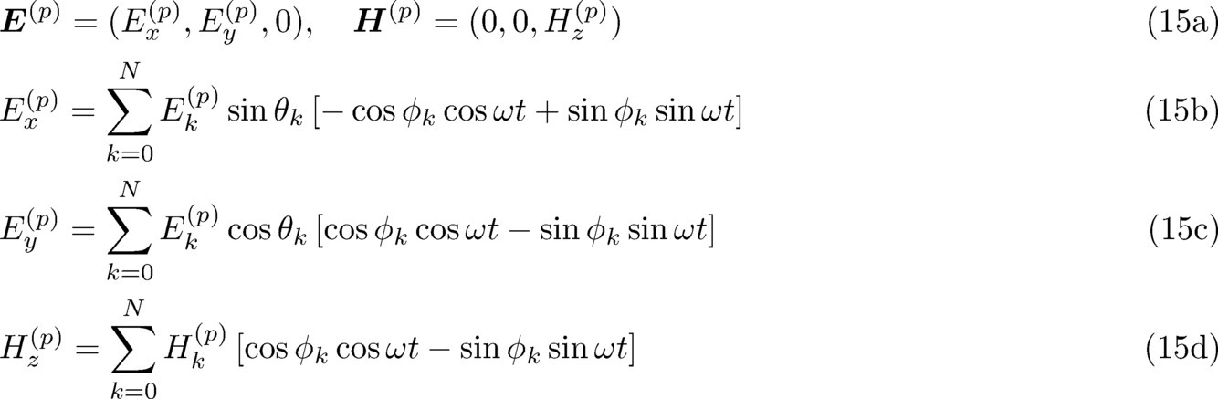
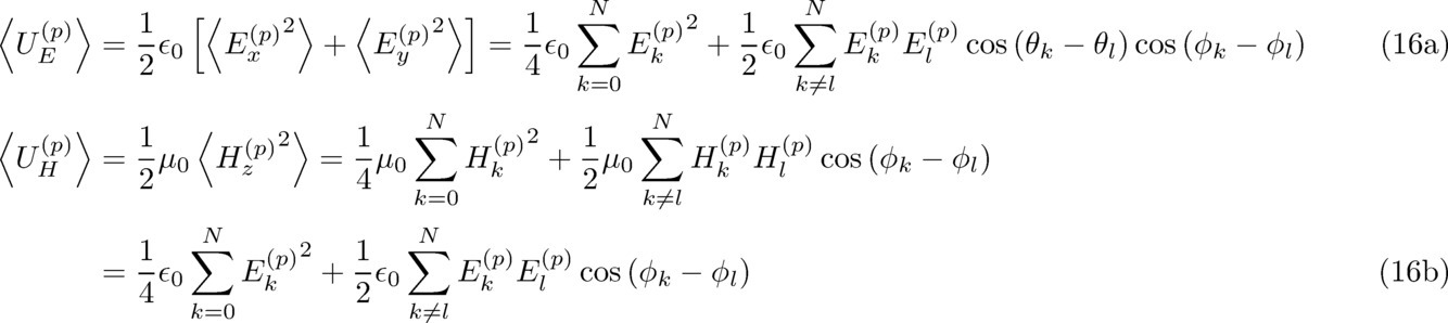


(4.1)室内試験
次に、実際にビーコン(beacon)(RFセンサ)と受信器を用いて、水面による電波の受信状況の変化に関して実験を行った結果について説明する。図17は、実験室において実際にアクティブ型ビーコン(active beacon)を用いて、送信点Aと水面との距離の変化による受信強度の変化を測定した結果である。図17において横軸は時間、縦軸は受信強度(dB)を表す。また、図18は、図17の測定の測定条件を示す図である。測定は、水槽内にポールを設置して、125cm間隔で高さを変えてアクティブ型ビーコンを設置し、水槽に水を注水しながら水槽外部の受信機で各ビーコンから送信される信号の受信強度を観測することによって実施した。図17の(a),(b),(c)の測定結果は、其々、図18の(a),(b),(c)のビーコンからの信号の受信強度を表している。
次に、実際の外部環境に於いて行った試験測定結果について説明する。河川増水や洪水のような発生頻度の極めて低い事象での試験は事実上困難であるため、今回の外部環境測定試験は、海岸に於ける潮の干満を利用して試験を実施した。外部環境測定試験の実施場所は、干満差のある干潟で行った。図20は、外部環境測定試験で使用した試験システムの外観写真である。図20(a)はRFセンサ2の設置状態を示す写真であり、図20(b)は電波受信測定系の設置状態を示す写真である。干潟に沓石ブロック(deck block)を設置して、沓石ブロックに支柱を立てて、この支柱の高さの異なる3カ所に、其々、RFセンサ2を固定した。沓石ブロックの上面から各RFセンサ2までの高さは、其々、39.7cm,79.7cm,118.2cmとした(図20(a)の左下小図参照)。各RFセンサ2は、自発発信型のものを使用し、1秒毎に電波応答信号を発信するように設定した。また、電波応答信号の使用周波数帯域は2.4GHzを用い、スペクトル拡散通信による通信を行うように設定した。また、電波応答信号の受信と同時に、そのときの水深も測定するため、沓石ブロックの上面に水深センサを設置した。尚、干潟地面から沓石ブロック上面までの高さは約20cmとしたため、沓石ブロックの周囲の水位が20cmを超えた場合に水深センサにより水深が検出される。また、電波受信測定系は、図20(b)に示した様に、海岸の堤防上に設置した。沓石ブロックから電波受信測定系の受信アンテナまでの水平距離は6.6m、沓石ブロックが設置された干潟地面から受信アンテナまでの垂直距離は4.2mとした。受信アンテナは、S偏光を最も高感度で受信できるように、電界が水平方向に振動する電波の受信感度が最大となる向きとなるように設置した。また、電波受信測定時における実際の水面の様子も同時に記録するため、受信アンテナの脇にビデオカメラを設置してRFセンサ2の周囲の撮影を行った。
次に、水位変化が大きい福岡県の筑後川の河口付近に於いて水位検出試験を行った試験測定結果について説明する。この試験では、浸水検出装置1と各RFセンサ2との間の通信方式として、Bluetooth 5.0(登録商標)規格を使用した。無線周波数帯域は2.4 GHzである。RFセンサからの電波応答信号の間隔は10秒とした。図26-図28に、浸水検出装置1及び各RFセンサ2a,2b,2cを設置した場所の周辺環境とそれらの位置関係を示す。図27に示すように、河川の岸付近に立てられた木杭に、3つのRFセンサ2a,2b,2cを、約50cm間隔で高さを変えて固定設置した。この各RFセンサ2の設置場所の隣には、国土交通省の水位計が設置されており、各時刻の水位に関してはこの水位計の観測データを利用した。図28に示すように、浸水検出装置1は、RFセンサ2を設置した川岸の対岸にある建物の屋上に設置した。浸水検出装置1と各RFセンサ2との位置関係は、図26に示すように、河川を挟み、水平距離で80.2m、垂直距離で15.0m、直線距離で81.6m(測量値)とし、浸水検出装置1から各RFセンサ2が直接見通せるようにした。

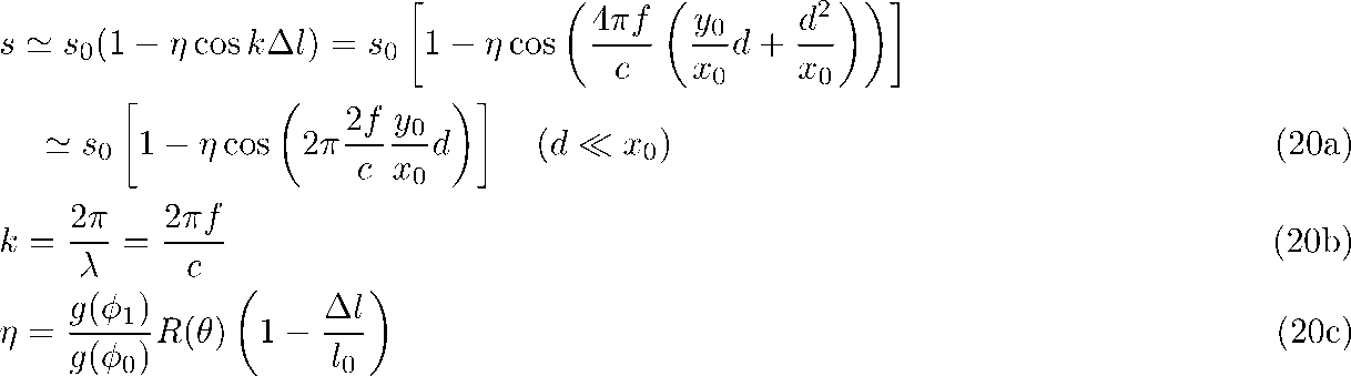

最後に、本実施例の浸水検出システムの動作について説明する。本実施例の浸水検出システムにおける浸水検出装置1では、RFセンサ2からの電波応答信号の受信信号強度I(t)の一定時間Δt1内の分散値σ2(I;[t-Δt1,t])と一定時間Δt2内の正常受信率R([t-Δt2,t])の閾値判定により、RFセンサ2の浸水を検出する。また、分散値σ2(I;[t-Δt1,t])の閾値判定、又は受信信号強度変動度|DI(t)|の閾値判定を用いて、RFセンサ2の周辺の地面の冠水を検出する。そのため、これらの閾値判定の際の閾値を適切な値に設定する必要がある。然し乍ら、受信信号強度I(t)やその分散値σ2(I;[t-Δt1,t])、正常受信率R([t-Δt2,t])等は、RFセンサ2と浸水検出装置1が設置される周辺環境に依存して変化すると考えられる。従って、本実施例の浸水検出装置1では、地面が冠水していない平時において受信信号強度I(t)、分散値σ2(I;[t-Δt1,t])、正常受信率R([t-Δt2,t])等をサンプリングして、機械学習によって其々の閾値を周囲環境に適応して設定する。
(判定条件1)受信強度散布度検出部22が出力する分散値σ2(I;[t-Δt1,t])が閾値σ2 th2に対してσ2(I;[t-Δt1,t])≧σ2 th2となった。
(判定条件2)一定のサンプリング時間Δt3内にVRSS |DI(t)|が閾値DIthを超えた回数NDIが、所定の閾値NDIthを超えた。
上記(判定条件1)又は(判定条件2)が満たされた場合には、浸水注意報判定部28は、浸水注意信号を出力し、上位通信I/Fモジュール14は、浸水注意信号を、上位通信アンテナ15を介して上位ネットワークへ送信する(S8)。







また、MUSIC法によりAPSを測定する場合、方位スペクトル検出部31は、次のような統計計算によってAPS PMU(θ)の算出を行う。





2 RFセンサ
2a アレイRFセンサ
2b 基板
2c 送受信モジュール
2d アンテナ切替器
2d アンテナ素子
11 センサ通信アンテナ
11a アレイアンテナ
11b 移相器
11c 加算器
12 送受信I/Fモジュール
13 コンピュータ
14 上位通信I/Fモジュール
15 上位通信アンテナ
16 初期化スイッチ
21 受信強度検出部
22 受信強度散布度検出部
23 分散閾値設定部
24 正常受信率検出部
25 正常受信率閾値設定部
26 受信強度変動検出部
26a 強度変動閾値設定部
27 浸水判定部
28 浸水注意報判定部
29 判定信号送信部
30 ウエイト設定部
31 方位スペクトル検出部
32 水位推定部
33 水位信号送信部
35 干渉波形検出部
36 干渉波形シフト量検出部
Claims (8)
- 浸水検出を行う箇所に設置された、間歇的に電波信号を無線発信するRFセンサから送信される、前記電波信号を受信して受信信号として出力する受信アンテナと、
各時刻tにおいて、前記受信アンテナより出力される前記受信信号の強度である受信信号強度I(t)を検出する受信信号強度検出手段と、
各時刻tにおいて、前記受信信号強度検出手段が検出する前記受信信号強度I(t)の一定時間Δt1内の散布度D(I;[t-Δt1,t])を検出する受信信号強度散布度検出手段と、
各時刻tにおいて、一定の時間Δt2内に前記受信信号が正常に受信された割合である正常受信率R([t-Δt2,t])を検出する正常受信率検出手段と、
前記受信信号強度散布度検出手段が出力する前記散布度D(I;[t-Δt1,t])が所定の閾値Dth1以上で、且つ前記正常受信率検出手段が出力する前記正常受信率R([t-Δt2,t])が所定の閾値Rth1以下となった場合に、浸水検出信号を出力する浸水検出判定手段と、を備えたことを特徴とする浸水検出装置。 - 前記受信信号強度散布度検出手段が出力する前記散布度D(I;[t-Δt1,t])が所定の閾値Dth2以上となった場合に、浸水注意信号を出力する浸水注意報判定手段を備えたことを特徴とする請求項1記載の浸水検出装置。
- 各時刻tにおいて、前記受信信号強度I(t)の時間変化値DI(t)=I(t)-I(t-δt)又はI(t)/I(t-δt)の絶対値である受信信号強度変動度|DI(t)|を検出する受信信号強度変動検出手段と、
一定の時間Δt3内に前記受信信号強度変動度|DI(t)|が所定の閾値DIthを超えた回数NDIが、所定の閾値NDIthを超えた場合に、浸水注意信号を出力する浸水注意報判定手段を備えたことを特徴とする請求項1記載の浸水検出装置。 - 浸水検出を行う箇所に設置された、間歇的に電波信号を無線発信するRFセンサと、
前記RFセンサから離隔して、前記RFセンサよりも高所に設置された請求項1乃至3の何れか一に記載の浸水検出装置と、を備えたことを特徴とする浸水検出システム。 - 前記受信アンテナは、水平方向の電界成分の受信信号強度が最大となる向きに設置されていることを特徴とする請求項4記載の浸水検出システム。
- 浸水検出箇所が浸水したか否かを検出する浸水検出方法であって、
前記浸水検出箇所に設置されたRFセンサから送信される電波信号を、前記RFセンサよりも高所に設置された受信アンテナにより受信し、
前記電波信号から電気信号である受信信号を生成し、
各時刻に於いて、前記受信信号の強度である受信信号強度I(t)、該受信信号強度I(t)の一定時間Δt1内の散布度D(I;[t-Δt1,t])、及び一定の時間Δt2内に前記受信信号が正常に受信された割合である正常受信率R([t-Δt2,t])を検出し、
前記散布度D(I;[t-Δt1,t])が所定の閾値Dth1以上で、且つ前記正常受信率R([t-Δt2,t])が所定の閾値Rth以下となった場合に、浸水が検出されたと判定することを特徴とする浸水検出方法。 - 前記散布度D(I;[t-Δt1,t])が所定の閾値Dth2以上となった場合に、浸水注意レベルに達したと判定することを特徴とする請求項6記載の浸水検出方法。
- 各時刻tにおいて、前記受信信号強度I(t)の時間変化値DI(t)=I(t)-I(t-δt)又はI(t)/I(t-δt)の絶対値である受信信号強度変動度|DI(t)|を検出するとともに、
一定の時間Δt3内に前記受信信号強度変動度|DI(t)|が所定の閾値DIthを超えた回数NDIが、所定の閾値NDIthを超えた場合に、浸水注意レベルに達したと判定することを特徴とする請求項6記載の浸水検出方法。
Priority Applications (3)
| Application Number | Priority Date | Filing Date | Title |
|---|---|---|---|
| US17/433,125 US11473959B2 (en) | 2019-04-24 | 2020-04-20 | Inundation detection device, inundation detection system, and inundation detection method |
| EP20793554.5A EP3916352B1 (en) | 2019-04-24 | 2020-04-20 | Inundation detection device, inundation detection system, and inundation detection method |
| JP2020564950A JP6858438B2 (ja) | 2019-04-24 | 2020-04-20 | 浸水検出装置、浸水検出システム、及び浸水検出方法 |
Applications Claiming Priority (4)
| Application Number | Priority Date | Filing Date | Title |
|---|---|---|---|
| JP2019082791 | 2019-04-24 | ||
| JP2019-082791 | 2019-04-24 | ||
| JP2019115927 | 2019-06-21 | ||
| JP2019-115927 | 2019-06-21 |
Publications (1)
| Publication Number | Publication Date |
|---|---|
| WO2020218258A1 true WO2020218258A1 (ja) | 2020-10-29 |
Family
ID=72942760
Family Applications (1)
| Application Number | Title | Priority Date | Filing Date |
|---|---|---|---|
| PCT/JP2020/017092 Ceased WO2020218258A1 (ja) | 2019-04-24 | 2020-04-20 | 浸水検出装置、浸水検出システム、及び浸水検出方法 |
Country Status (4)
| Country | Link |
|---|---|
| US (1) | US11473959B2 (ja) |
| EP (1) | EP3916352B1 (ja) |
| JP (1) | JP6858438B2 (ja) |
| WO (1) | WO2020218258A1 (ja) |
Cited By (5)
| Publication number | Priority date | Publication date | Assignee | Title |
|---|---|---|---|---|
| JP2022096915A (ja) * | 2020-12-18 | 2022-06-30 | ソフトバンク株式会社 | 浸水検知装置、浸水検知システム、及びサーバ |
| JP2024065622A (ja) * | 2022-10-31 | 2024-05-15 | セイコーエプソン株式会社 | 情報処理装置およびプログラム |
| JP2024085015A (ja) * | 2022-12-14 | 2024-06-26 | 太平洋工業株式会社 | 災害監視装置 |
| WO2024190175A1 (ja) * | 2023-03-14 | 2024-09-19 | パナソニックIpマネジメント株式会社 | 物理量計測システム |
| JP2024538562A (ja) * | 2021-09-24 | 2024-10-23 | ハイドロ レーダー,エルエルシー | 流体系用の流量及び水位モニタ |
Families Citing this family (5)
| Publication number | Priority date | Publication date | Assignee | Title |
|---|---|---|---|---|
| JP7402336B2 (ja) * | 2020-06-16 | 2023-12-20 | 住友商事株式会社 | 推定システム、推定方法、および推定プログラム |
| US12092754B2 (en) * | 2021-04-13 | 2024-09-17 | Aurora Operations, Inc | Detection or correction for multipath reflection |
| CN116295037B (zh) * | 2023-04-11 | 2023-11-14 | 广东省水利水电建设有限公司 | 一种生态坡体监控方法 |
| CN116539088B (zh) * | 2023-05-05 | 2023-11-17 | 青岛海威茨仪表有限公司 | 一种用于仪表的泡水深度判断方法、检测系统及方法 |
| CN117238109B (zh) * | 2023-09-15 | 2024-10-01 | 中交基础设施养护西藏有限公司 | 基于复杂地质环境的远程监控危险预警系统 |
Citations (8)
| Publication number | Priority date | Publication date | Assignee | Title |
|---|---|---|---|---|
| JP2000298055A (ja) | 1999-04-15 | 2000-10-24 | Nippon Signal Co Ltd:The | 水位検知装置及び異常水位警報装置 |
| US6586760B1 (en) * | 1999-11-03 | 2003-07-01 | The United States Of America As Represented By The Secretary Of The Interior | Water level measuring method and system |
| JP2010156672A (ja) * | 2008-12-05 | 2010-07-15 | Sumitomo Osaka Cement Co Ltd | 構造物における水の検知方法及び構造物用部材並びに構造物における水の検知装置 |
| JP2010170190A (ja) | 2009-01-20 | 2010-08-05 | Unimation System Inc | 河川水位警報ユニット |
| JP2013109558A (ja) | 2011-11-21 | 2013-06-06 | Tec Okazaki:Kk | 洪水発生警報装置及びこれを用いた洪水発生警報システム |
| JP2015129709A (ja) * | 2014-01-08 | 2015-07-16 | 住友電工システムソリューション株式会社 | 水位センサ、水位検知システム、水分量センサおよび水分量検知システム。 |
| JP2016065824A (ja) * | 2014-09-25 | 2016-04-28 | 沖電気工業株式会社 | 水位判定システム、判定装置及びプログラム |
| JP2017227485A (ja) * | 2016-06-21 | 2017-12-28 | 富士電機株式会社 | 浸水検出システムおよび浸水検出方法 |
Family Cites Families (9)
| Publication number | Priority date | Publication date | Assignee | Title |
|---|---|---|---|---|
| KR100793448B1 (ko) * | 2004-10-25 | 2008-01-14 | 교세라 가부시키가이샤 | 용기 장치 및 정보 제공 장치 |
| US7458260B2 (en) * | 2005-11-07 | 2008-12-02 | Claridy Solutions, Inc. | Fluid level detection using RF |
| DE102007027171A1 (de) * | 2007-06-13 | 2009-01-02 | Siemens Ag | Verfahren zur Messung der Höhe eines Flüssigkeitsstands sowie eine zugehörige Anordnung |
| TWI475847B (zh) * | 2008-04-16 | 2015-03-01 | 皇家飛利浦電子股份有限公司 | 存在及移動偵測之被動雷達 |
| US7830302B1 (en) * | 2008-05-05 | 2010-11-09 | The United States Of America As Represented By The Secretary Of The Navy | Remote sensing of wave heights using a narrowband radar arrangement |
| US7808426B1 (en) * | 2008-05-05 | 2010-10-05 | The United States Of America As Represented By The Secretary Of The Navy | Remote sensing of wave heights using a broadband radar arrangement |
| DE102013100817A1 (de) * | 2013-01-28 | 2014-07-31 | Sick Ag | Mikrowellenschranke und Verfahren zur Erkennung eines Objekts in einem Mikrowellenpfad |
| US10228439B1 (en) * | 2017-10-31 | 2019-03-12 | Cognitive Systems Corp. | Motion detection based on filtered statistical parameters of wireless signals |
| JP6783417B1 (ja) * | 2020-05-15 | 2020-11-11 | 三菱電機株式会社 | 水位監視システムおよび水位監視方法 |
-
2020
- 2020-04-20 WO PCT/JP2020/017092 patent/WO2020218258A1/ja not_active Ceased
- 2020-04-20 US US17/433,125 patent/US11473959B2/en active Active
- 2020-04-20 JP JP2020564950A patent/JP6858438B2/ja active Active
- 2020-04-20 EP EP20793554.5A patent/EP3916352B1/en active Active
Patent Citations (8)
| Publication number | Priority date | Publication date | Assignee | Title |
|---|---|---|---|---|
| JP2000298055A (ja) | 1999-04-15 | 2000-10-24 | Nippon Signal Co Ltd:The | 水位検知装置及び異常水位警報装置 |
| US6586760B1 (en) * | 1999-11-03 | 2003-07-01 | The United States Of America As Represented By The Secretary Of The Interior | Water level measuring method and system |
| JP2010156672A (ja) * | 2008-12-05 | 2010-07-15 | Sumitomo Osaka Cement Co Ltd | 構造物における水の検知方法及び構造物用部材並びに構造物における水の検知装置 |
| JP2010170190A (ja) | 2009-01-20 | 2010-08-05 | Unimation System Inc | 河川水位警報ユニット |
| JP2013109558A (ja) | 2011-11-21 | 2013-06-06 | Tec Okazaki:Kk | 洪水発生警報装置及びこれを用いた洪水発生警報システム |
| JP2015129709A (ja) * | 2014-01-08 | 2015-07-16 | 住友電工システムソリューション株式会社 | 水位センサ、水位検知システム、水分量センサおよび水分量検知システム。 |
| JP2016065824A (ja) * | 2014-09-25 | 2016-04-28 | 沖電気工業株式会社 | 水位判定システム、判定装置及びプログラム |
| JP2017227485A (ja) * | 2016-06-21 | 2017-12-28 | 富士電機株式会社 | 浸水検出システムおよび浸水検出方法 |
Non-Patent Citations (2)
| Title |
|---|
| NOBUYOSHI KIKUMA: "Adaptive signal processing with array antenna", 1998, KAGAKU GIJUTSU SHUPPAN, INC. |
| See also references of EP3916352A4 |
Cited By (6)
| Publication number | Priority date | Publication date | Assignee | Title |
|---|---|---|---|---|
| JP2022096915A (ja) * | 2020-12-18 | 2022-06-30 | ソフトバンク株式会社 | 浸水検知装置、浸水検知システム、及びサーバ |
| JP2024538562A (ja) * | 2021-09-24 | 2024-10-23 | ハイドロ レーダー,エルエルシー | 流体系用の流量及び水位モニタ |
| JP2024065622A (ja) * | 2022-10-31 | 2024-05-15 | セイコーエプソン株式会社 | 情報処理装置およびプログラム |
| JP2024085015A (ja) * | 2022-12-14 | 2024-06-26 | 太平洋工業株式会社 | 災害監視装置 |
| JP7836750B2 (ja) | 2022-12-14 | 2026-03-27 | 太平洋工業株式会社 | 災害監視装置 |
| WO2024190175A1 (ja) * | 2023-03-14 | 2024-09-19 | パナソニックIpマネジメント株式会社 | 物理量計測システム |
Also Published As
| Publication number | Publication date |
|---|---|
| US20220042838A1 (en) | 2022-02-10 |
| US11473959B2 (en) | 2022-10-18 |
| JPWO2020218258A1 (ja) | 2021-09-13 |
| EP3916352A1 (en) | 2021-12-01 |
| EP3916352A4 (en) | 2022-05-11 |
| JP6858438B2 (ja) | 2021-04-14 |
| EP3916352B1 (en) | 2025-11-12 |
Similar Documents
| Publication | Publication Date | Title |
|---|---|---|
| JP6858438B2 (ja) | 浸水検出装置、浸水検出システム、及び浸水検出方法 | |
| CN105474041B (zh) | 气象信息处理装置、气象雷达系统及气象信息处理方法 | |
| CN106772300B (zh) | 一种微波超视距雷达回波图计算方法 | |
| CN102608604B (zh) | 基于共极化特征功率图的海面溢油检测方法 | |
| Tatiparthi et al. | Development of radio-frequency identification (RFID) sensors suitable for smart-monitoring applications in sewer systems | |
| Lentini et al. | Global sensitivity of parabolic equation radar wave propagation simulation to sea state and atmospheric refractivity structure | |
| CN103278804B (zh) | 一种波导超视距雷达 | |
| TWI397714B (zh) | 定位方法及其系統 | |
| CN101317074A (zh) | 用于液体液位检测的湿汽排流雷达天线 | |
| NO20111748A1 (no) | Portabel radar for bestemmelse av oljeutslipps fordelig og tykkelse | |
| JP6137961B2 (ja) | 海洋レーダ装置 | |
| CN103344957A (zh) | 一种波导超视距海浪监测雷达 | |
| Ji et al. | Target monitoring using small-aperture compact high-frequency surface wave radar | |
| JP2015129709A (ja) | 水位センサ、水位検知システム、水分量センサおよび水分量検知システム。 | |
| Chen et al. | Ship echo identification based on norm-constrained adaptive beamforming for an arrayed high-frequency coastal radar | |
| CN105334506B (zh) | 一种基于雷达回波中线谱强度估计海面风速的方法和装置 | |
| US10809369B2 (en) | Radar signal processing apparatus and radar signal processing method | |
| CN103108281A (zh) | 一种基于无线传感器网络的海上搜救目标实时定位方法 | |
| US20240125598A1 (en) | System for simultaneously measuring surface flow velocities at multiple points in stream using digital beamforming radar | |
| Fillinger et al. | Towards a passive acoustic underwater system for protecting harbours against intruders | |
| CN118068289B (zh) | 高频地波雷达数据处理方法及系统 | |
| Zhou et al. | Portable high frequency surface wave radar OSMAR-S | |
| Titchenko et al. | Sub-satellite validation using ultrasonic wave gauge: In-situ measurements of surface waves slope variance and other parameters of surface waves | |
| Hamza et al. | IDENTIFYING SOME REGULARITIES OF RADIO FREQUENCY PROPAGATION OF A RADAR SYSTEM BY ANALYZING DIFFERENT ENVIRONMENTAL EFFECTS. | |
| KR102665656B1 (ko) | 스마트부이에 체결된 어구의 위치를 측정하는 방법 및 어구 위치 측정 시스템 |
Legal Events
| Date | Code | Title | Description |
|---|---|---|---|
| ENP | Entry into the national phase |
Ref document number: 2020564950 Country of ref document: JP Kind code of ref document: A |
|
| 121 | Ep: the epo has been informed by wipo that ep was designated in this application |
Ref document number: 20793554 Country of ref document: EP Kind code of ref document: A1 |
|
| ENP | Entry into the national phase |
Ref document number: 2020793554 Country of ref document: EP Effective date: 20210824 |
|
| NENP | Non-entry into the national phase |
Ref country code: DE |
|
| WWG | Wipo information: grant in national office |
Ref document number: 2020793554 Country of ref document: EP |