WO2020218266A1 - 画像表示装置 - Google Patents
画像表示装置 Download PDFInfo
- Publication number
- WO2020218266A1 WO2020218266A1 PCT/JP2020/017119 JP2020017119W WO2020218266A1 WO 2020218266 A1 WO2020218266 A1 WO 2020218266A1 JP 2020017119 W JP2020017119 W JP 2020017119W WO 2020218266 A1 WO2020218266 A1 WO 2020218266A1
- Authority
- WO
- WIPO (PCT)
- Prior art keywords
- display panel
- antenna
- display device
- image display
- plate portion
- Prior art date
- Legal status (The legal status is an assumption and is not a legal conclusion. Google has not performed a legal analysis and makes no representation as to the accuracy of the status listed.)
- Ceased
Links
Images






Classifications
-
- G—PHYSICS
- G06—COMPUTING OR CALCULATING; COUNTING
- G06F—ELECTRIC DIGITAL DATA PROCESSING
- G06F1/00—Details not covered by groups G06F3/00 - G06F13/00 and G06F21/00
- G06F1/16—Constructional details or arrangements
- G06F1/18—Packaging or power distribution
- G06F1/181—Enclosures
- G06F1/182—Enclosures with special features, e.g. for use in industrial environments; grounding or shielding against radio frequency interference [RFI] or electromagnetical interference [EMI]
-
- G—PHYSICS
- G06—COMPUTING OR CALCULATING; COUNTING
- G06F—ELECTRIC DIGITAL DATA PROCESSING
- G06F1/00—Details not covered by groups G06F3/00 - G06F13/00 and G06F21/00
- G06F1/16—Constructional details or arrangements
- G06F1/1601—Constructional details related to the housing of computer displays, e.g. of CRT monitors, of flat displays
-
- H—ELECTRICITY
- H01—ELECTRIC ELEMENTS
- H01Q—ANTENNAS, i.e. RADIO AERIALS
- H01Q1/00—Details of, or arrangements associated with, antennas
- H01Q1/12—Supports; Mounting means
- H01Q1/22—Supports; Mounting means by structural association with other equipment or articles
-
- H—ELECTRICITY
- H04—ELECTRIC COMMUNICATION TECHNIQUE
- H04N—PICTORIAL COMMUNICATION, e.g. TELEVISION
- H04N5/00—Details of television systems
- H04N5/64—Constructional details of receivers, e.g. cabinets or dust covers
Definitions
- the present disclosure relates to an image display device including an antenna unit.
- Patent Document 1 discloses a liquid crystal television provided with a slot antenna.
- a slot antenna is housed in a conductive member above the liquid crystal panel, and the slot antenna receives radio waves transmitted from an external interrogator.
- the present disclosure provides an image display device capable of improving reception performance.
- the image display device in the present disclosure includes a display panel for displaying an image on the front surface, an antenna portion provided so as to be located in front of the front surface of the display panel, and a non-conductive member accommodating the antenna portion. To be equipped.
- reception performance can be improved.
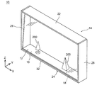
- FIG. 1 is an external perspective view showing a state in which the image display device according to the first embodiment is operating in the first transmission mode.
- FIG. 2 is an external perspective view showing a state in which the image display device according to the first embodiment is operating in the image display mode.
- FIG. 3 is an external perspective view showing a state in which the image display device according to the first embodiment is operating in the second transmission mode.
- FIG. 4 is an exploded perspective view showing the vicinity of the lower plate portion of the image display device according to the first embodiment.
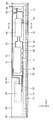
- FIG. 5 is a plan view showing a control unit of the image display device according to the first embodiment.
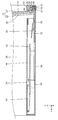
- FIG. 6 is a sectional view taken along line VI-VI of FIG. FIG.
- FIG. 7 is an external perspective view showing a state in which the image display device according to the second embodiment is operating in the first transmission mode.
- FIG. 8 is an exploded perspective view showing the vicinity of the upper plate portion of the image display device according to the second embodiment.
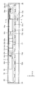
- FIG. 9 is a plan view showing a control unit of the image display device according to the second embodiment.
- FIG. 10 is a cross-sectional view taken along line XX of FIG.
- FIG. 11 is a perspective view showing an image display device according to another embodiment.
- the inventor of the present application has found that the following problems occur with respect to the conventional liquid crystal television.
- the slot antenna is housed in the conductive member above the liquid crystal panel, the reception performance is deteriorated.
- the vertical direction is matched with the Z-axis direction
- the front-back direction is matched with the Y-axis direction
- the left-right direction is matched with the X-axis direction.
- the posture of the image display device according to the present disclosure at the time of manufacture or use is not limited.
- the X-axis plus side indicates the arrow direction side of the X-axis
- the X-axis minus side indicates the side opposite to the X-axis plus side. The same applies to the Y-axis direction and the Z-axis direction.
- FIG. 1 is an external perspective view showing a state in which the image display device 10 according to the first embodiment is operating in the first transmission mode.
- FIG. 2 is an external perspective view showing a state in which the image display device 10 according to the first embodiment is operating in the image display mode.
- FIG. 3 is an external perspective view showing a state in which the image display device 10 according to the first embodiment is operating in the second transmission mode.
- FIG. 4 is an exploded perspective view showing the vicinity of the lower plate portion 24 of the image display device 10 according to the first embodiment.
- FIG. 5 is a plan view showing a control unit 16 of the image display device 10 according to the first embodiment.
- FIG. 6 is a sectional view taken along line VI-VI of FIG. In order to avoid complicating the drawings, the source substrate 52 and the like are not shown in FIG. Further, in order to make the drawing easier to understand, in FIG. 5, the cover portion 34 and the like are not shown, and the lower edge portion of the display panel 12 is shown by a two-dot chain line.
- the image display device 10 includes a display panel 12, a housing 14, and a control unit 16.
- the image display device 10 is an image display device that can be connected to Wifi (registered trademark) or the like by an antenna portion 54 (described later) or the like provided near the lower edge portion of the display panel 12.
- Wifi registered trademark
- antenna portion 54 described later
- the display panel 12 has an image display mode for displaying an image on the front surface 13 and a transparent state in which an object on the back side of the display panel 12 can be visually recognized when viewed from the front. It is a display device that can be switched to the transmission mode, and has a rectangular shape when viewed from the front.
- the display panel 12 is an organic EL (electro-luminescence) panel, and is an organic light (OLED) arranged on a front glass plate 18 and a back side of the front glass plate 18. -Emitting diode) panel 20.
- organic EL elements having an EL layer and a transparent electrode sandwiching the EL layer are arranged in a matrix, and a region in which an image (including a background image) is not displayed is generally used. It has a degree of light transmission that is generally called transparent.
- the "image" displayed on the display panel 12 may be either a still image or a moving image, or may be video content including both a still image and a moving image.
- the display panel 12 for example, as shown in FIG. 1, by not displaying an image on the display panel 12, the object 200 on the back side of the display panel 12 becomes a visible first transmission mode. Further, as shown in FIG. 2, the image display mode is set by displaying the image 202 in the entire area of the image display area of the display panel 12. Further, as shown in FIG. 3, by displaying the partial image 204 in a part of the image display area of the display panel 12, the object 200 on the back side of the display panel 12 can be visually recognized while displaying the partial image 204. It becomes a bitransparent mode. Further, the display panel 12 may have an optical member such as an antireflection film and a dimming panel in addition to the components described above.
- the front surface 13 of the display panel 12 is the front surface of the front glass plate 18.
- the display panel 12 does not have to have the front glass plate 18, and when the display panel 12 does not have the front glass plate 18, the front surface of the display panel 12 is the front surface of the OLED panel 20.
- the housing 14 is provided along the edge of the display panel 12 and supports the display panel 12.
- the housing 14 supports the display panel 12 so that the display panel 12 is slightly tilted rearward.
- the housing 14 includes an upper plate portion 22 provided along the upper edge portion of the display panel 12, a lower plate portion 24 provided along the lower edge portion, a left plate portion 26 provided along the left edge portion, and a right side. It has a right plate portion 28 provided along the edge portion.
- the upper plate portion 22, the lower plate portion 24, the left plate portion 26, and the right plate portion 28 are plate-shaped, respectively.
- the upper plate portion 22, the lower plate portion 24, the left plate portion 26, and the right plate portion 28 project forward and rearward from the display panel 12, respectively.
- the upper plate portion 22 and the lower plate portion 24 are provided parallel to each other, and the left plate portion 26 and the right plate portion 28 are provided parallel to each other.
- the upper plate portion 22 has a groove portion (not shown) recessed upward, and the upper edge portion of the display panel 12 is housed in the groove portion.
- the lower plate portion 24 has a bottom plate portion 30, a front wall portion 32, and a cover portion 34.
- the bottom plate portion 30 extends in the left-right direction, and a control portion 16 and the like are provided on the bottom plate portion 30.
- the bottom plate portion 30 has a notch portion 31 that cuts out the front edge portion of the bottom plate portion 30.
- the cutout portion 31 is recessed rearward at the front edge portion of the bottom plate portion 30 and extends in the left-right direction.
- the notch portion 31 is formed to the right of the central portion of the bottom plate portion 30 in the left-right direction.
- a lid 40 (described later) is arranged in the notch 31.
- the front wall portion 32 has a main body portion 35, a housing portion 36, a notch portion 38, and a lid portion 40.
- the main body 35 extends in the left-right direction along the lower edge of the display panel 12 in front of the lower edge of the display panel 12 and is fixed to the front edge of the bottom plate 30. In this way, the main body portion 35 is provided so as to project forward from the lower edge portion of the display panel 12.
- the main body 35 is located in front of the front surface 13 of the display panel 12 and overlaps the display panel 12 in the front-rear direction. Specifically, the main body 35 is located in front of the lower edge of the front surface 13 of the display panel 12 and overlaps the lower edge of the display panel 12 in the front-rear direction.
- the accommodating portion 36 is a portion accommodating the antenna portion 54, and is formed to the right of the central portion of the main body portion 35 in the left-right direction.
- the accommodating portion 36 opens on the lower surface of the main body portion 35, that is, opens downward, and is recessed upward.
- the accommodating portion 36 is located above the notch portion 31 and extends in the left-right direction along the notch portion 31.
- the accommodating portion 36 is located to the right of the central portion of the display panel 12 in the left-right direction. Further, the accommodating portion 36 is located in front of the front surface 13 of the display panel 12, and overlaps with the display panel 12 in the front-rear direction.
- the accommodating portion 36 is located in front of the lower edge portion of the front surface 13 of the display panel 12, and overlaps the lower edge portion of the display panel 12 in the front-rear direction.
- the cutout portion 38 is a portion through which an electric wire 72 (described later) connecting the antenna portion 54 and the communication board 56 (described later) passes, and is formed so as to cut out the main body portion 35 behind the accommodating portion 36.
- the lid portion 40 is a member that supports the antenna portion 54 from below. The lid portion 40 extends in the left-right direction and is provided in the accommodating portion 36 so as to close the opening 42 of the accommodating portion 36.
- the lid portion 40 is attached to the main body portion 35 by two bolts 44.
- the cover portion 34 is provided above the bottom plate portion 30 so as to cover the control portion 16 and the like.
- the front edge portion of the cover portion 34 is provided at a distance from the front wall portion 32 in the front-rear direction.
- the lower plate portion 24 accommodates the lower edge portion of the display panel 12 by inserting the lower edge portion of the display panel 12 between the front wall portion 32 and the front edge portion of the cover portion 34.
- An object 200 (photograph, doll, vase, toy, model, painting, etc.) can be placed on the upper surface of the cover portion 34, and when the display panel 12 operates in the transparent mode, the user can place the display panel 12 on the upper surface. Through this, the object 200 placed on the upper surface of the cover portion 34 can be visually recognized.
- the element accommodated in the lower plate portion 24 is not limited to the control unit 16, and for example, a speaker device (exhaust fan, a television tuner, an optical disk player, etc.) (not shown) may be accommodated.
- the left plate portion 26 connects the left edge portion of the upper plate portion 22 and the left edge portion of the lower plate portion 24.
- the left plate portion 26 has a groove portion (not shown) recessed to the left, and the left edge portion of the display panel 12 is housed in the groove portion.
- the right plate portion 28 connects the right edge portion of the upper plate portion 22 and the right edge portion of the lower plate portion 24.
- the right plate portion 28 has a groove portion 29 recessed to the right, and the groove portion 29 accommodates the right edge portion of the display panel 12.
- the front wall portion 32 corresponds to a non-conductive member, and the front wall portion 32 constitutes a part of the housing 14.
- control unit 16 As shown in FIGS. 4 to 6, the control unit 16 is housed in the lower plate unit 24 and controls the operation of the display panel 12.
- the control unit 16 includes a power supply board 46, a signal board 48, a T-con board 50, two source boards 52, an antenna unit 54, and a communication board 56.
- the antenna portion 54 is provided in front of the lower edge portion of the display panel 12, and the power supply board 46, the signal board 48, the T-con board 50, the two source boards 52, and the communication board 56 are below the display panel 12. It is provided behind the edge.
- the antenna portion 54 is provided in front of the lower edge portion of the front surface 13 of the display panel 12, and includes a power supply board 46, a signal board 48, a T-con board 50, two source boards 52, and a communication board. 56 is provided behind the lower edge of the front surface 13 of the display panel 12.
- the power supply board 46 is connected to an external power source (not shown) via the electric wire 58, connected to the signal board 48 via the electric wire 60, and connected to the T-con board 50 via the electric wire 62.
- the power supply board 46 supplies electric power from an external power source to the signal board 48, the T-con board 50, and the like.
- the power supply board 46 is provided on the right side of the central portion of the bottom plate portion 30 in the left-right direction.
- the signal board 48 is connected to the communication board 56 via the electric wire 64, and sends and receives signals to and from the communication board 56. Further, the signal board 48 is connected to the T-con board 50 via the electric wire 66, and sends and receives signals to and from the T-con board 50.
- the signal board 48 is provided on the left side of the central portion of the bottom plate portion 30 in the left-right direction.
- the T-con board 50 constitutes a so-called timing controller, and is connected to two source boards 52 via a flexible printed circuit board 68.
- the T-con board 50 generates various signals such as a clock signal for distributing the image data displayed on the display panel 12 to each pixel of the display panel 12, and supplies the signals to the source board 52.
- the T-con substrate 50 is provided at the center of the bottom plate portion 30 in the left-right direction.
- the two source boards 52 are connected to the display panel 12 via the flexible printed circuit board 70, and supply a signal from the T-con board 50 to the display panel 12.
- the two source boards 52 are adjacent to each other and are provided in front of the power supply board 46, the signal board 48, the T-con board 50, and the communication board 56.
- the antenna portion 54 is connected to the communication board 56 via the electric wire 72.
- the antenna unit 54 transmits and receives radio waves for communication between the communication board 56 and another communication device (not shown) according to the Wifi (registered trademark) standard, for example.
- the antenna portion 54 extends in the left-right direction and has a plate shape.
- the antenna portion 54 is accommodated in the accommodating portion 36 in an upright posture, and is provided near the lower edge portion of the display panel 12.
- the antenna portion 54 is located to the right of the central portion of the main body portion 35 in the left-right direction and the central portion of the display panel 12 in the left-right direction. Further, the antenna portion 54 is located in front of the front surface 13 of the display panel 12 and overlaps with the display panel 12 in the front-rear direction.
- the antenna portion 54 is located in front of the lower edge portion of the front surface 13 of the display panel 12, and overlaps the lower edge portion of the display panel 12 in the front-rear direction. Further, the entire antenna portion 54 is located in front of the lower edge portion of the front surface 13 of the display panel 12.
- the antenna portion 54 is supported from below by the lid portion 40.
- the front, upper, left, and right sides of the antenna portion 54 are covered with the main body portion 35, and the lower portion of the antenna portion 54 is covered with the lid portion 40.
- the entire antenna portion 54 does not have to be located in front of the lower edge portion of the front surface 13 of the display panel 12.
- at least a part of the antenna portion 54 is below the front surface 13 of the display panel 12. It may be located in front of the edge.
- a conductive material such as metal can be used.
- the antenna portion 54 is composed of a metal member and a resin that covers at least a part of the metal member.
- the communication board 56 communicates with other communication devices via the antenna unit 54. Further, the communication board 56 transmits / receives a signal to / from the signal board 48.
- the communication board 56 is provided on the right side of the central portion of the bottom plate portion 30 in the left-right direction, and slightly closer to the center than the right edge portion of the bottom plate portion 30. The communication board 56 is located to the right of the central portion of the display panel 12 and the antenna portion 54 in the left-right direction.
- the image display device 10 includes a display panel 12 for displaying an image on the front surface 13 and an antenna portion 54 provided so as to be located in front of the front surface 13 of the display panel 12. , And a front wall portion 32 for accommodating the antenna portion 54.
- the antenna portion 54 is provided so as to be located in front of the front surface 13 of the display panel 12. As a result, for example, even if the image display device 10 is installed near the wall, it is possible to suppress the radio waves received by the antenna unit 54 from being blocked by the wall, and the reception performance of the antenna unit 54 can be improved. Further, the antenna portion 54 is accommodated in the accommodating portion 36 of the front wall portion 32. As a result, it is possible to suppress a decrease in the sensitivity of the antenna portion 54 and improve the reception performance of the antenna portion 54 as compared with the case where the antenna portion 54 is housed in the conductive member. Further, this makes it possible to suppress the antenna unit 54 from being seen by the user and improve the appearance of the image display device 10, and also suppress the user from directly touching the antenna unit 54 to improve safety. it can.
- the image display device 10 further includes a communication board 56 provided behind the display panel 12 and capable of communicating with the antenna unit 54.
- the reception performance of the antenna unit 54 can be improved while suppressing the communication board 56 from being seen by the user in front of the display panel 12.
- the front wall portion 32 has an accommodating portion 36 that opens downward and accommodates the antenna portion 54, and a lid portion 40 provided in the accommodating portion 36.
- the accommodating portion 36 opens downward, the reception performance of the antenna portion 54 can be improved while suppressing the viewing of the antenna portion 54 and the lid portion 40 from the user in front of the display panel 12.
- the image display device 10 further includes a housing 14 provided along the edge of the display panel 12, and the front wall portion 32 constitutes a part of the housing 14. ..
- the antenna portion 54 can be accommodated without separately providing a member for accommodating the antenna portion 54.
- the antenna portion 54 is provided so as to overlap the display panel 12 in the front-rear direction.
- the reception performance of the antenna unit 54 is improved while suppressing the image display device 10 from becoming larger in the vertical direction and the horizontal direction as compared with the case where the antenna unit 54 does not overlap the display panel 12 in the front-rear direction. Can be improved.
- the front wall portion 32 is provided along the lower edge portion of the display panel 12 and is provided so as to project forward from the display panel 12.
- the antenna unit 54 can be arranged near the lower edge portion of the display panel 12, the antenna unit suppresses that the image displayed on the display panel 12 overlaps with the antenna unit 54 and makes the image difficult to see.
- the reception performance of 54 can be improved.
- FIG. 7 is an external perspective view showing a state in which the image display device 10a according to the second embodiment is operating in the first transmission mode.
- FIG. 8 is an exploded perspective view showing the vicinity of the upper plate portion 22a of the image display device 10a according to the second embodiment.
- FIG. 9 is a plan view showing a control unit 16a of the image display device 10a according to the second embodiment.
- FIG. 10 is a cross-sectional view taken along line XX of FIG. In order to avoid complicating the drawings, the source substrate 52a and the like are not shown in FIG. Further, in order to make the drawing easier to understand, in FIG. 9, the upper plate portion 22a and the like are not shown, and the upper edge portion of the display panel 12 is shown by a two-dot chain line.
- the image display device 10a includes a display panel 12, a housing 14a, a control unit 16a, and an illumination unit 74.
- the image display device 10a is an image display device that can be connected to Wifi (registered trademark) or the like by an antenna portion 54 or the like provided near the upper edge portion of the display panel 12.
- Wifi registered trademark
- antenna portion 54 or the like provided near the upper edge portion of the display panel 12.
- the housing 14a has an upper plate portion 22a, a lower plate portion 24a, a left plate portion 26, and a right plate portion 28.
- the upper plate portion 22a, the lower plate portion 24a, the left plate portion 26, and the right plate portion 28 project forward and rearward from the display panel 12, respectively.
- the upper plate portion 22a has a main body portion 75 and a groove portion 76.
- the main body portion 75 extends in the left-right direction and is provided along the upper edge portion of the display panel 12.
- the main body 75 projects forward and backward from the display panel 12.
- the main body 75 is located in front of the front surface 13 of the display panel 12 and overlaps the display panel 12 in the front-rear direction.
- the main body 75 is located in front of the upper edge of the front surface 13 of the display panel 12 and overlaps the upper edge of the display panel 12 in the front-rear direction.
- the groove portion 76 is a groove portion in which the upper edge portion of the display panel 12 is housed, and is opened on the lower surface of the main body portion 75, that is, is opened downward, and is recessed upward.
- the groove portion 76 extends in the left-right direction along the upper edge portion of the display panel 12.
- the upper plate portion 22a has an accommodating portion 36a, a groove portion 38a, and a lid portion 40.
- the accommodating portion 36a is a portion accommodating the antenna portion 54, and is formed to the right of the central portion of the main body portion 75 in the left-right direction.
- the accommodating portion 36a opens on the lower surface of the main body portion 75, that is, opens downward, and is recessed upward.
- the accommodating portion 36a extends in the left-right direction.
- the accommodating portion 36a is located to the right of the central portion of the display panel 12 in the left-right direction. Further, the accommodating portion 36a is located in front of the front surface 13 of the display panel 12, and overlaps with the display panel 12 in the front-rear direction. Specifically, the accommodating portion 36a is located in front of the upper edge portion of the front surface 13 of the display panel 12, and overlaps the upper edge portion of the display panel 12 in the front-rear direction.
- the groove 38a is a portion through which the electric wire 72a (described later) connecting the antenna portion 54 and the communication board 56a (described later) passes. The groove 38a opens on the lower surface of the main body 75, that is, opens downward, and is recessed upward.
- the groove 38a communicates with the accommodating portion 36a, extends rearward from the accommodating portion 36a, and then extends to the right.
- the lid portion 40 is a member that supports the antenna portion 54 from below, and is provided in the accommodating portion 36a.
- the lid portion 40 is attached to the main body portion 75 by two bolts 44.
- the lower plate portion 24a has a groove portion (not shown) recessed downward, and the lower edge portion of the display panel 12 is housed in the groove portion.
- the left plate portion 26 and the right plate portion 28 detailed description thereof will be omitted by referring to the description in the first embodiment described above.
- a non-conductive material such as wood or resin
- the upper plate portion 22a corresponds to a non-conductive member, and the upper plate portion 22a constitutes a part of the housing 14.
- control unit 16a As shown in FIGS. 8 to 10, the control unit 16a is supported by the upper plate portion 22a on the lower surface side of the upper plate portion 22a, and controls the operations of the display panel 12 and the illumination unit 74.
- the control unit 16a includes a power supply board 46a, a signal board 48a, a T-con board 50a, two source boards 52a, an antenna part 54, a communication board 56a, and a support part 77.
- the power supply board 46a, the signal board 48a, the T-con board 50a, and the two source boards 52a will be omitted in detail by referring to the above description in the first embodiment.
- the antenna portion 54 is connected to the communication board 56a via the electric wire 72a.
- the antenna unit 54 transmits and receives radio waves for, for example, the communication board 56a and another communication device (not shown) to perform communication in accordance with the Wifi (registered trademark) standard.
- the antenna portion 54 extends in the left-right direction and has a plate shape.
- the antenna portion 54 is accommodated in the accommodating portion 36a in an upright posture, and is provided near the upper edge portion of the display panel 12.
- the antenna portion 54 is located to the right of the central portion of the main body portion 75 in the left-right direction and the central portion of the display panel 12 in the left-right direction. Further, the antenna portion 54 is located in front of the front surface 13 of the display panel 12.
- the antenna portion 54 is located in front of the upper edge portion of the front surface 13 of the display panel 12. Further, the entire antenna portion 54 is located in front of the upper edge portion of the front surface 13 of the display panel 12.
- the antenna portion 54 is supported from below by the lid portion 40.
- the front, upper, left, and right sides of the antenna portion 54 are covered with the main body portion 75, and the lower portion of the antenna portion 54 is covered with the lid portion 40.
- the antenna portion 54 is a display panel.
- the entire antenna portion 54 does not have to be located in front of the upper edge portion of the front surface 13 of the display panel 12, for example, at least a part of the antenna portion 54 is above the front surface 13 of the display panel 12. It may be located in front of the edge. Further, the antenna portion 54 may overlap with the display panel 12 in the front-rear direction. Specifically, the antenna portion 54 may overlap the upper edge portion of the display panel 12 in the front-rear direction.
- a conductive material such as metal can be used.
- the antenna portion 54 is composed of a metal member and a resin that covers at least a part of the metal member.
- the communication board 56a communicates with other communication devices via the antenna unit 54. Further, the communication board 56a transmits / receives a signal to / from the signal board 48a.
- the communication board 56a is provided on the right side of the central portion of the support portion 77 in the left-right direction and slightly closer to the center than the right edge portion of the support portion 77. The communication board 56a is located to the right of the central portion of the display panel 12 and the antenna portion 54 in the left-right direction.
- the support portion 77 extends in the left-right direction, is attached to the lower surface of the upper plate portion 22a, and connects the left plate portion 26 and the right plate portion 28.
- the support portion 77 has a bottom portion 78, a left side portion 80, a right side portion 82, and a back portion 84.
- the bottom portion 78 extends in the left-right direction and has a plate shape, and is provided substantially parallel to the upper plate portion 22a.
- the front edge portion of the bottom portion 78 is formed in a substantially inverted U shape in cross section (see FIG. 10), and the illumination portion 74 is supported by the front edge portion of the bottom portion 78.
- the left side portion 80 projects upward from the left edge portion of the bottom portion 78 and is provided along the left plate portion 26.
- the left side portion 80 is fixed to the left plate portion 26 by bolts or the like (not shown).
- the right side portion 82 projects upward from the right edge portion of the bottom portion 78 and is provided along the right plate portion 28.
- the right side portion 82 is fixed to the right plate portion 28 by bolts or the like (not shown).
- the left side portion 80 is fixed to the left plate portion 26, and the right side portion 82 is fixed to the right plate portion 28, so that the support portion 77 connects the left plate portion 26 and the right plate portion 28.
- the back portion 84 projects upward from the trailing edge of the bottom portion 78.
- the upper edge portion of the back portion 84 is folded back and fixed to the upper plate portion 22a by a bolt (not shown).
- a conductive material such as metal can be used as the material of the support portion 77.
- the illumination unit 74 is provided at the leading edge of the bottom portion 78 of the support unit 77, and is electrically connected to the control unit 16a via an electric wire (not shown).
- the display panel 12 is arranged with fine light-shielding elements such as an organic EL element and a liquid crystal dispersedly arranged, the light transmittance is, for example, 40 even when operating in the transmission mode. It is about% to 50%. Therefore, for example, when the image display device 10a is placed in a relatively dark environment, the user may not be able to clearly see the object 200 on the back side of the display panel 12. However, the light emitted from the illumination unit 74 can illuminate the object 200 on the back side of the display panel 12.
- the illumination unit 74 is embedded in the front edge portion of the bottom portion 78, so that when the display panel 12 is in a transmitted state, the light emitted from the illumination unit 74 exists in front of the image display device 10a. It is possible to prevent the user from directly seeing the image.
- the illumination unit 74 has a substrate 86 that is elongated in the left-right direction, and a plurality of LED elements 88 that are mounted on the substrate 86 and emit light.
- the illumination unit 74 configured as described above illuminates one or more objects 200 placed on the lower plate portion 24a.
- the upper plate portion 22a is provided along the upper edge portion of the display panel 12 and is provided so as to project forward from the display panel 12. ..
- the antenna unit 54 can be arranged near the upper edge portion of the display panel 12, the antenna unit suppresses that the image displayed on the display panel 12 overlaps with the antenna unit 54 and makes the image difficult to see.
- the reception performance of 54 can be improved.
- the display panel 12 has an image display mode in which an image is displayed on the front surface 13 and a transmission mode in which an object on the back side of the display panel 12 is in a visible transparent state when viewed from the front.
- the display panel 12b may be a liquid crystal panel or the like that cannot switch between the image display mode and the transmission mode.
- the antenna portion 54 may be provided so as to be located in front of the front surface of the display panel 12b (see FIG. 11).
- the antenna portion 54 is housed in the lower plate portion 24 provided along the lower edge portion of the display panel 12, and the upper plate portion provided along the upper edge portion of the display panel 12.
- the antenna portion 54 may be housed in a left plate portion 26 provided along the left edge portion of the display panel 12, or may be housed in a right plate portion 28 provided along the right edge portion of the display panel 12. May be good.
- the antenna portion 54 and the accommodating portion 36 are located to the right of the central portion of the display panel 12 in the left-right direction, and the antenna portion 54 and the accommodating portion 36a are the display panel 12 in the left-right direction.
- the antenna portion and the accommodating portion may be located at the center of the display panel 12 in the left-right direction, or may be located to the left of the center of the display panel 12 in the left-right direction.
- the housing 14 has a plate-shaped upper plate portion 22, a lower plate portion 24, a left plate portion 26, and a right plate portion 28, and the housing 14a has a plate-shaped upper plate portion.
- the housing may have an upper frame portion such as a prism, a lower frame portion, a left frame portion, and a right frame portion.
- the housing 14 supports the display panel 12 so that the display panel 12 is slightly tilted rearward has been described, but the present invention is not limited to this.
- the housing may support the display panel 12 so that the display panel 12 does not tilt in the front-rear direction.
- the antenna portion 54 has a plate shape
- the present invention is not limited to this.
- the antenna portion may be rod-shaped, tubular, columnar, or the like.
- the antenna portion may have a meander shape or the like.
- the present disclosure is applicable to a television receiver, a monitor display, or an image display device such as digital signage.
Landscapes
- Engineering & Computer Science (AREA)
- Theoretical Computer Science (AREA)
- Physics & Mathematics (AREA)
- General Engineering & Computer Science (AREA)
- Computer Hardware Design (AREA)
- Human Computer Interaction (AREA)
- General Physics & Mathematics (AREA)
- Electromagnetism (AREA)
- Power Engineering (AREA)
- Multimedia (AREA)
- Signal Processing (AREA)
- Devices For Indicating Variable Information By Combining Individual Elements (AREA)
Abstract
本実施の形態に係る画像表示装置(10)は、前面(13)に画像を表示する表示パネル(12)と、表示パネル(12)の前面(13)よりも前方に位置するように設けられるアンテナ部(54)と、アンテナ部(54)を収容する前壁部(32)と、を備える。たとえば、アンテナ部(54)は、前後方向において、表示パネル(12)と重なるように設けられる。また、たとえば、前壁部(32)は、表示パネル(12)の下縁部に沿って設けられかつ表示パネル(12)よりも前方に突出するように設けられる。
Description
本開示は、アンテナ部を備える画像表示装置に関する。
特許文献1は、スロットアンテナを備える液晶テレビを開示する。この液晶テレビでは、液晶パネルの上方において、スロットアンテナが導電性部材に収容されており、外部の質問機から発信された電波をスロットアンテナで受信する。
本開示は、受信性能を向上できる画像表示装置を提供する。
本開示における画像表示装置は、前面に画像を表示する表示パネルと、前記表示パネルの前記前面よりも前方に位置するように設けられるアンテナ部と、前記アンテナ部を収容する非導電性部材と、を備える。
本開示における画像表示装置によれば、受信性能を向上できる。
本願発明者は、従来の液晶テレビに関し、以下の問題が生じることを見出した。上記従来の液晶テレビでは、液晶パネルの上方において、スロットアンテナが導電性部材に収容されているため、受信性能が低下してしまう。
本開示は、このような知見に基づいてなされたものであり、本願発明者が鋭意検討した結果、受信性能を向上できる画像表示装置の構造についての着想を得た。
以下、適宜図面を参照しながら実施の形態を説明する。但し、必要以上に詳細な説明は省略する場合がある。たとえば、既によく知られた事項の詳細説明や実質的に同一の構成に対する重複説明を省略する場合がある。これは、以下の説明が不必要に冗長になるのを避け、当業者の理解を容易にするためである。また、各図は、必ずしも厳密に図示したものではない。
なお、本願発明者は、当業者が本開示を十分に理解するために添付図面および以下の説明を提供するのであって、これらによって請求の範囲に記載の主題を限定することを意図するものではない。
また、以下の実施の形態において、説明の便宜上、上下方向をZ軸方向と一致させ、前後方向をY軸方向と一致させ、左右方向をX軸方向と一致させているが、これら対応付けは、本開示に係る画像表示装置の製造時または使用時における姿勢を限定するものではない。また、以下の説明において、たとえば、X軸プラス側とは、X軸の矢印方向側を示し、X軸マイナス側とは、X軸プラス側とは反対側を示す。Y軸方向およびZ軸方向についても同様である。
さらに、以下の実施の形態において、平行および直交等の、2つの方向の相対的な姿勢を示す表現が用いられる場合があるが、これらの表現は、厳密にはその姿勢ではない場合も含む。たとえば、2つの方向が平行である、という場合、特に断りのない限り、当該2つの方向が完全に平行であることを意味するだけでなく、実質的に平行であること、すなわち、たとえば数%程度の差異を含むことも意味する。
以下、図面を用いて実施の形態について説明する。
<実施の形態1>
まず、実施の形態1について説明する。
まず、実施の形態1について説明する。
図1は、実施の形態1に係る画像表示装置10の、第一透過モードで動作している状態を示す外観斜視図である。図2は、実施の形態1に係る画像表示装置10の、画像表示モードで動作している状態を示す外観斜視図である。図3は、実施の形態1に係る画像表示装置10の、第二透過モードで動作している状態を示す外観斜視図である。図4は、実施の形態1に係る画像表示装置10の、下板部24近傍を示す分解斜視図である。図5は、実施の形態1に係る画像表示装置10の、制御部16を示す平面図である。図6は、図5のVI-VI線断面図である。なお、図面が煩雑になることを避けるため、図4ではソース基板52等の図示を省略する。また、図面をわかりやすくするため、図5では、カバー部34等の図示を省略し、表示パネル12の下縁部を二点鎖線で示す。
[画像表示装置の構成]
図1および図4に示すように、本実施の形態に係る画像表示装置10は、表示パネル12、筐体14、および制御部16を備える。画像表示装置10は、表示パネル12の下縁部近傍に設けられるアンテナ部54(後述)等によって、Wifi(登録商標)等に接続可能な画像表示装置である。以下、各構成について説明する。
図1および図4に示すように、本実施の形態に係る画像表示装置10は、表示パネル12、筐体14、および制御部16を備える。画像表示装置10は、表示パネル12の下縁部近傍に設けられるアンテナ部54(後述)等によって、Wifi(登録商標)等に接続可能な画像表示装置である。以下、各構成について説明する。
(表示パネル)
図1から図3に示すように、表示パネル12は、前面13に画像を表示する画像表示モードと、前方から見た場合に、表示パネル12の背面側の物体が視認可能な透過状態となる透過モードとの切り替えが可能なディスプレイ装置であり、前方から見たとき矩形状である。具体的には、図6に示すように、表示パネル12は、有機EL(electro-luminescence)パネルであって、前面ガラス板18と、前面ガラス板18の背面側に配置されるOLED(organic light-emitting diode)パネル20とを有する。本実施の形態において、OLEDパネル20では、EL層と、EL層を挟む透明電極とを有する有機EL素子がマトリクス状に配列されており、画像(背景画像を含む)を表示しない領域は、一般的に透明と呼ばれる程度の光透過性を有している。表示パネル12に表示される「画像」は、静止画および動画のいずれであってもよく、静止画および動画の両方を含む映像コンテンツであってもよい。
図1から図3に示すように、表示パネル12は、前面13に画像を表示する画像表示モードと、前方から見た場合に、表示パネル12の背面側の物体が視認可能な透過状態となる透過モードとの切り替えが可能なディスプレイ装置であり、前方から見たとき矩形状である。具体的には、図6に示すように、表示パネル12は、有機EL(electro-luminescence)パネルであって、前面ガラス板18と、前面ガラス板18の背面側に配置されるOLED(organic light-emitting diode)パネル20とを有する。本実施の形態において、OLEDパネル20では、EL層と、EL層を挟む透明電極とを有する有機EL素子がマトリクス状に配列されており、画像(背景画像を含む)を表示しない領域は、一般的に透明と呼ばれる程度の光透過性を有している。表示パネル12に表示される「画像」は、静止画および動画のいずれであってもよく、静止画および動画の両方を含む映像コンテンツであってもよい。
上記の表示パネル12では、たとえば、図1に示すように、表示パネル12に画像を表示させないことで、表示パネル12の背面側の物体200が視認可能な第一透過モードとなる。また、図2に示すように、表示パネル12の画像表示領域の全域に画像202を表示させることで、画像表示モードとなる。さらに、図3に示すように、表示パネル12の画像表示領域の一部に部分画像204を表示させることによって、部分画像204を表示させつつ表示パネル12の背面側の物体200が視認可能な第二透過モードとなる。また、表示パネル12は、上記説明された構成要素の他、たとえば、反射防止フィルムおよび調光パネル等の光学部材を有していてもよい。また、本実施の形態では、表示パネル12の前面13は、前面ガラス板18の前面である。なお、表示パネル12は、前面ガラス板18を有していなくてもよく、表示パネル12が前面ガラス板18を有していない場合、表示パネル12の前面は、OLEDパネル20の前面である。
(筐体)
図1に示すように、筐体14は、表示パネル12の縁部に沿って設けられ、表示パネル12を支持する。筐体14は、表示パネル12がやや後方に傾くように、表示パネル12を支持する。筐体14は、表示パネル12の上縁部に沿って設けられる上板部22、下縁部に沿って設けられる下板部24、左縁部に沿って設けられる左板部26、および右縁部に沿って設けられる右板部28を有する。上板部22、下板部24、左板部26および右板部28はそれぞれ、板状である。上板部22、下板部24、左板部26および右板部28はそれぞれ、表示パネル12よりも前方および後方に突出する。上板部22および下板部24は、相互に平行に設けられ、左板部26および右板部28は、相互に平行に設けられる。
図1に示すように、筐体14は、表示パネル12の縁部に沿って設けられ、表示パネル12を支持する。筐体14は、表示パネル12がやや後方に傾くように、表示パネル12を支持する。筐体14は、表示パネル12の上縁部に沿って設けられる上板部22、下縁部に沿って設けられる下板部24、左縁部に沿って設けられる左板部26、および右縁部に沿って設けられる右板部28を有する。上板部22、下板部24、左板部26および右板部28はそれぞれ、板状である。上板部22、下板部24、左板部26および右板部28はそれぞれ、表示パネル12よりも前方および後方に突出する。上板部22および下板部24は、相互に平行に設けられ、左板部26および右板部28は、相互に平行に設けられる。
上板部22は、上方に凹む溝部(図示せず)を有し、当該溝部には、表示パネル12の上縁部が収容される。
図4から図6に示すように、下板部24は、底板部30、前壁部32、およびカバー部34を有する。底板部30は、左右方向に延び、底板部30上には、制御部16等が設けられる。底板部30は、底板部30の前縁部を切り欠く切り欠き部31を有する。切り欠き部31は、底板部30の前縁部において後方に凹み、かつ左右方向に延びる。切り欠き部31は、左右方向における底板部30の中央部よりも右方に形成されている。切り欠き部31には、蓋部40(後述)が配置される。前壁部32は、本体部35、収容部36、切り欠き部38、および蓋部40を有する。本体部35は、表示パネル12の下縁部よりも前方において、表示パネル12の下縁部に沿って左右方向に延び、底板部30の前縁部に固定される。このように、本体部35は、表示パネル12の下縁部よりも前方に突出するように設けられる。本体部35は、表示パネル12の前面13よりも前方に位置しており、前後方向において表示パネル12と重なっている。具体的には、本体部35は、表示パネル12の前面13の下縁部よりも前方に位置しており、前後方向において表示パネル12の下縁部と重なっている。収容部36は、アンテナ部54を収容する部分であり、左右方向における本体部35の中央部よりも右方に形成されている。収容部36は、本体部35の下面において開口すなわち下方に開口し、上方に凹む。収容部36は、切り欠き部31の上方に位置し、切り欠き部31に沿って左右方向に延びる。収容部36は、左右方向における表示パネル12の中央部よりも右方に位置している。また、収容部36は、表示パネル12の前面13よりも前方に位置しており、前後方向において表示パネル12と重なっている。具体的には、収容部36は、表示パネル12の前面13の下縁部よりも前方に位置しており、前後方向において表示パネル12の下縁部と重なっている。切り欠き部38は、アンテナ部54と通信基板56(後述)とを繋ぐ電線72(後述)が通る部分であり、収容部36の後方において、本体部35を切り欠くように形成されている。蓋部40は、アンテナ部54を下方から支持する部材である。蓋部40は、左右方向に延び、収容部36の開口42を塞ぐように、収容部36に設けられる。蓋部40は、2つのボルト44によって、本体部35に取り付けられる。カバー部34は、制御部16等を覆うように、底板部30の上方に設けられる。カバー部34の前縁部は、前後方向において前壁部32と間隔を空けて設けられる。下板部24は、前壁部32とカバー部34の前縁部との間に表示パネル12の下縁部を挿入することによって、表示パネル12の下縁部を収容する。カバー部34の上面には、物体200(写真、人形、花瓶、玩具、模型、または絵画等)を載置可能であり、表示パネル12が透過モードで動作する場合、ユーザは、表示パネル12を介して、カバー部34の上面に載置された物体200を視認することができる。なお、下板部24に収容される要素は、制御部16には限定されず、たとえば、図示しないスピーカ装置、排気ファン、テレビチューナおよび光ディスクプレーヤ等が収容されてもよい。
左板部26は、上板部22の左縁部と下板部24の左縁部とを連結する。左板部26は、左方に凹む溝部(図示せず)を有し、当該溝部には、表示パネル12の左縁部が収容される。右板部28は、上板部22の右縁部と下板部24の右縁部とを連結する。右板部28は、右方に凹む溝部29を有し、溝部29には、表示パネル12の右縁部が収容される。
上板部22、左板部26、右板部28、本体部35、および蓋部40の材料としては、たとえば、木材または樹脂等の非導電性材料を用いることができる。底板部30およびカバー部34の材料としては、たとえば、金属等の導電性材料を用いることができる。本実施の形態では、前壁部32が非導電性部材に相当し、前壁部32は、筐体14の一部を構成している。
(制御部)
図4から図6に示すように、制御部16は、下板部24に収容され、表示パネル12の動作を制御する。制御部16は、電源基板46、信号基板48、T-con基板50、2つのソース基板52、アンテナ部54、および通信基板56を有する。アンテナ部54は、表示パネル12の下縁部よりも前方に設けられ、電源基板46、信号基板48、T-con基板50、2つのソース基板52、および通信基板56は、表示パネル12の下縁部よりも後方に設けられる。具体的には、アンテナ部54は、表示パネル12の前面13の下縁部よりも前方に設けられ、電源基板46、信号基板48、T-con基板50、2つのソース基板52、および通信基板56は、表示パネル12の前面13の下縁部よりも後方に設けられる。
図4から図6に示すように、制御部16は、下板部24に収容され、表示パネル12の動作を制御する。制御部16は、電源基板46、信号基板48、T-con基板50、2つのソース基板52、アンテナ部54、および通信基板56を有する。アンテナ部54は、表示パネル12の下縁部よりも前方に設けられ、電源基板46、信号基板48、T-con基板50、2つのソース基板52、および通信基板56は、表示パネル12の下縁部よりも後方に設けられる。具体的には、アンテナ部54は、表示パネル12の前面13の下縁部よりも前方に設けられ、電源基板46、信号基板48、T-con基板50、2つのソース基板52、および通信基板56は、表示パネル12の前面13の下縁部よりも後方に設けられる。
電源基板46は、電線58を介して外部電源(図示せず)に接続され、電線60を介して信号基板48に接続され、電線62を介してT-con基板50に接続される。電源基板46は、外部電源からの電力を、信号基板48およびT-con基板50等に供給する。電源基板46は、左右方向における底板部30の中央部よりも右方に設けられる。
信号基板48は、電線64を介して通信基板56に接続され、通信基板56に対して信号の送受信を行う。また、信号基板48は、電線66を介してT-con基板50に接続され、T-con基板50に対して信号の送受信を行う。信号基板48は、左右方向における底板部30の中央部よりも左方に設けられる。
T-con基板50は、いわゆるタイミングコントローラを構成しており、フレキシブルプリント基板68を介して2つのソース基板52に接続される。T-con基板50は、表示パネル12に表示される画像データを表示パネル12が有する各画素に分配するためのクロック信号等の各種信号を生成し、当該信号をソース基板52に供給する。T-con基板50は、左右方向における底板部30の中央部に設けられる。
2つのソース基板52は、フレキシブルプリント基板70を介して表示パネル12に接続され、T-con基板50からの信号を表示パネル12に供給する。2つのソース基板52は、相互に隣り合い、電源基板46、信号基板48、T-con基板50、および通信基板56よりも前方に設けられる。
アンテナ部54は、電線72を介して通信基板56に接続される。アンテナ部54は、たとえば、通信基板56と他の通信機器(図示せず)とがWifi(登録商標)規格に従った通信を行うための電波を送受信する。アンテナ部54は、左右方向に延びかつ板状である。アンテナ部54は、上下方向に立設する姿勢で収容部36に収容され、表示パネル12の下縁部近傍に設けられる。アンテナ部54は、左右方向における本体部35の中央部および左右方向における表示パネル12の中央部よりも右方に位置している。また、アンテナ部54は、表示パネル12の前面13よりも前方に位置し、前後方向において表示パネル12と重なっている。具体的には、アンテナ部54は、表示パネル12の前面13の下縁部よりも前方に位置し、前後方向において表示パネル12の下縁部と重なっている。また、アンテナ部54の全体が、表示パネル12の前面13の下縁部よりも前方に位置している。アンテナ部54は、蓋部40によって下方から支持される。アンテナ部54の前方、上方、左方、および右方は、本体部35に覆われており、アンテナ部54の下方は、蓋部40に覆われている。なお、アンテナ部54の全体が、表示パネル12の前面13の下縁部よりも前方に位置していなくてもよく、たとえば、アンテナ部54の少なくとも一部が、表示パネル12の前面13の下縁部よりも前方に位置していてもよい。アンテナ部54の材料としては、たとえば、金属等の導電性材料を用いることができる。具体的には、たとえば、アンテナ部54は、金属部材と、金属部材の少なくとも一部を覆う樹脂とで構成されている。
通信基板56は、アンテナ部54を介して他の通信機器と通信を行う。また、通信基板56は、信号基板48に対して信号の送受信を行う。通信基板56は、左右方向において、底板部30の中央部よりも右方であって、底板部30の右縁部よりもやや中央よりに設けられる。通信基板56は、左右方向において、表示パネル12の中央部およびアンテナ部54よりも右方に位置する。
[効果等]
以上説明したように、本実施の形態に係る画像表示装置10は、前面13に画像を表示する表示パネル12と、表示パネル12の前面13よりも前方に位置するように設けられるアンテナ部54と、アンテナ部54を収容する前壁部32と、を備える。
以上説明したように、本実施の形態に係る画像表示装置10は、前面13に画像を表示する表示パネル12と、表示パネル12の前面13よりも前方に位置するように設けられるアンテナ部54と、アンテナ部54を収容する前壁部32と、を備える。
この構成によれば、表示パネル12の前面13よりも前方に位置するようにアンテナ部54が設けられる。これによって、たとえば、画像表示装置10を壁際に設置したとしても、アンテナ部54が受信する電波が壁に遮られることを抑制でき、アンテナ部54の受信性能を向上できる。また、アンテナ部54は、前壁部32の収容部36に収容される。これによって、アンテナ部54が導電性部材に収容される場合に比べて、アンテナ部54の感度が低下することを抑制でき、アンテナ部54の受信性能を向上できる。また、これによって、アンテナ部54がユーザから見えることを抑制し、画像表示装置10の見栄えを良くすることができるとともに、ユーザが直接的にアンテナ部54に触れることを抑制し、安全性を向上できる。
また、本実施の形態に係る画像表示装置10は、さらに、表示パネル12よりも後方に設けられかつアンテナ部54と通信可能な通信基板56を備える。
この構成によれば、表示パネル12の後方に通信基板56が設けられるので、表示パネル12の前方にいるユーザから通信基板56が見えることを抑制しつつ、アンテナ部54の受信性能を向上できる。
また、本実施の形態に係る画像表示装置10において、前壁部32は、下方に開口しかつアンテナ部54を収容する収容部36と、収容部36に設けられる蓋部40とを有する。
この構成によれば、収容部36が下方に開口するので、表示パネル12の前方にいるユーザからアンテナ部54および蓋部40が見えることを抑制しつつ、アンテナ部54の受信性能を向上できる。
また、本実施の形態に係る画像表示装置10は、さらに、表示パネル12の縁部に沿って設けられる筐体14を備え、前壁部32は、筐体14の一部を構成している。
この構成によれば、前壁部32が筐体14の一部を構成しているので、別途アンテナ部54を収容する部材を設けることなく、アンテナ部54を収容できる。
上述した作用効果については、後述する実施の形態2においても同様に奏することができる。
また、本実施の形態に係る画像表示装置10において、アンテナ部54は、前後方向において、表示パネル12と重なるように設けられる。
この構成によれば、アンテナ部54が前後方向において表示パネル12と重ならない場合に比べて、画像表示装置10が上下方向および左右方向に大きくなることを抑制しつつ、アンテナ部54の受信性能を向上できる。
また、本実施の形態に係る画像表示装置10において、前壁部32は、表示パネル12の下縁部に沿って設けられかつ表示パネル12よりも前方に突出するように設けられる。
この構成によれば、アンテナ部54を表示パネル12の下縁部近傍に配置できるので、表示パネル12に表示された画像がアンテナ部54と重なり当該画像が見にくくなることを抑制しつつ、アンテナ部54の受信性能を向上できる。
<実施の形態2>
ついで、実施の形態2について説明する。
ついで、実施の形態2について説明する。
図7は、実施の形態2に係る画像表示装置10aの、第一透過モードで動作している状態を示す外観斜視図である。図8は、実施の形態2に係る画像表示装置10aの、上板部22a近傍を示す分解斜視図である。図9は、実施の形態2に係る画像表示装置10aの、制御部16aを示す平面図である。図10は、図9のX-X線断面図である。なお、図面が煩雑になることを避けるため、図8ではソース基板52a等の図示を省略する。また、図面をわかりやすくするため、図9では、上板部22a等の図示を省略し、表示パネル12の上縁部を二点鎖線で示す。
[画像表示装置の構成]
図7から図10に示すように、本実施の形態に係る画像表示装置10aは、表示パネル12、筐体14a、制御部16a、および照明部74を備える。画像表示装置10aは、表示パネル12の上縁部近傍に設けられるアンテナ部54等によって、Wifi(登録商標)等に接続可能な画像表示装置である。以下、各構成について説明する。なお、以下の説明においては、実施の形態1に係る画像表示装置10との相違点を中心に説明する。表示パネル12については、上述した実施の形態1における説明を参照することによって、詳細な説明を省略する。
図7から図10に示すように、本実施の形態に係る画像表示装置10aは、表示パネル12、筐体14a、制御部16a、および照明部74を備える。画像表示装置10aは、表示パネル12の上縁部近傍に設けられるアンテナ部54等によって、Wifi(登録商標)等に接続可能な画像表示装置である。以下、各構成について説明する。なお、以下の説明においては、実施の形態1に係る画像表示装置10との相違点を中心に説明する。表示パネル12については、上述した実施の形態1における説明を参照することによって、詳細な説明を省略する。
(筐体)
図7に示すように、筐体14aは、上板部22a、下板部24a、左板部26、および右板部28を有する。上板部22a、下板部24a、左板部26および右板部28はそれぞれ、表示パネル12よりも前方および後方に突出する。
図7に示すように、筐体14aは、上板部22a、下板部24a、左板部26、および右板部28を有する。上板部22a、下板部24a、左板部26および右板部28はそれぞれ、表示パネル12よりも前方および後方に突出する。
図8から図10に示すように、上板部22aは、本体部75および溝部76を有する。本体部75は、左右方向に延び、表示パネル12の上縁部に沿って設けられる。本体部75は、表示パネル12よりも前方および後方に突出する。本体部75は、表示パネル12の前面13よりも前方に位置しており、前後方向において表示パネル12と重なっている。具体的には、本体部75は、表示パネル12の前面13の上縁部よりも前方に位置しており、前後方向において表示パネル12の上縁部と重なっている。溝部76は、表示パネル12の上縁部が収容される溝部であり、本体部75の下面において開口すなわち下方に開口し、上方に凹む。溝部76は、表示パネル12の上縁部に沿って左右方向に延びる。また、上板部22aは、収容部36a、溝部38a、および蓋部40を有する。収容部36aは、アンテナ部54を収容する部分であり、左右方向における本体部75の中央部よりも右方に形成されている。収容部36aは、本体部75の下面において開口すなわち下方に開口し、上方に凹む。収容部36aは、左右方向に延びる。収容部36aは、左右方向における表示パネル12の中央部よりも右方に位置している。また、収容部36aは、表示パネル12の前面13よりも前方に位置しており、前後方向において表示パネル12と重なっている。具体的には、収容部36aは、表示パネル12の前面13の上縁部よりも前方に位置しており、前後方向において表示パネル12の上縁部と重なっている。溝部38aは、アンテナ部54と通信基板56a(後述)とを繋ぐ電線72a(後述)が通る部分である。溝部38aは、本体部75の下面において開口すなわち下方に開口し、上方に凹む。溝部38aは、収容部36aと連通し、収容部36aから後方に延びた後、右方に延びる。蓋部40は、アンテナ部54を下方から支持する部材であり、収容部36a内に設けられる。蓋部40は、2つのボルト44によって、本体部75に取り付けられる。
下板部24aは、下方に凹む溝部(図示せず)を有し、当該溝部には、表示パネル12の下縁部が収容される。左板部26および右板部28については、上述した実施の形態1における説明を参照することによって、詳細な説明を省略する。
本体部75、蓋部40、下板部24a、左板部26、および右板部28の材料としては、たとえば、木材または樹脂等の非導電性材料を用いることができる。本実施の形態では、上板部22aが非導電性部材に相当し、上板部22aは、筐体14の一部を構成している。
(制御部)
図8から図10に示すように、制御部16aは、上板部22aの下面側において上板部22aに支持され、表示パネル12および照明部74の動作を制御する。制御部16aは、電源基板46a、信号基板48a、T-con基板50a、2つのソース基板52a、アンテナ部54、通信基板56a、および支持部77を有する。電源基板46a、信号基板48a、T-con基板50a、および2つのソース基板52aについては、上述した実施の形態1における説明を参照することによって、詳細な説明を省略する。
図8から図10に示すように、制御部16aは、上板部22aの下面側において上板部22aに支持され、表示パネル12および照明部74の動作を制御する。制御部16aは、電源基板46a、信号基板48a、T-con基板50a、2つのソース基板52a、アンテナ部54、通信基板56a、および支持部77を有する。電源基板46a、信号基板48a、T-con基板50a、および2つのソース基板52aについては、上述した実施の形態1における説明を参照することによって、詳細な説明を省略する。
アンテナ部54は、電線72aを介して通信基板56aに接続される。アンテナ部54は、たとえば、通信基板56aと他の通信機器(図示せず)とがWifi(登録商標)規格に従った通信を行うための電波を送受信する。アンテナ部54は、左右方向に延びかつ板状である。アンテナ部54は、上下方向に立設する姿勢で収容部36aに収容され、表示パネル12の上縁部近傍に設けられる。アンテナ部54は、左右方向における本体部75の中央部および左右方向における表示パネル12の中央部よりも右方に位置している。また、アンテナ部54は、表示パネル12の前面13よりも前方に位置している。具体的には、アンテナ部54は、表示パネル12の前面13の上縁部よりも前方に位置している。また、アンテナ部54の全体が、表示パネル12の前面13の上縁部よりも前方に位置している。アンテナ部54は、蓋部40によって下方から支持される。アンテナ部54の前方、上方、左方、および右方は、本体部75に覆われており、アンテナ部54の下方は、蓋部40に覆われている。本実施の形態のように、表示パネル12が後方に傾くように支持されている場合であって、アンテナ部54が表示パネル12の上縁部近傍に設けられる場合、アンテナ部54は、表示パネル12の前面13の少なくとも上縁部よりも前方に位置していればよく、表示パネル12の前面13の下縁部よりも後方に位置していてもよい。また、アンテナ部54の全体が、表示パネル12の前面13の上縁部よりも前方に位置していなくてもよく、たとえば、アンテナ部54の少なくとも一部が、表示パネル12の前面13の上縁部よりも前方に位置していてもよい。また、アンテナ部54は、前後方向において表示パネル12と重なっていてもよい。具体的には、アンテナ部54は、前後方向において表示パネル12の上縁部と重なっていてもよい。アンテナ部54の材料としては、たとえば、金属等の導電性材料を用いることができる。具体的には、たとえば、アンテナ部54は、金属部材と、金属部材の少なくとも一部を覆う樹脂とで構成されている。
通信基板56aは、アンテナ部54を介して他の通信機器と通信を行う。また、通信基板56aは、信号基板48aに対して信号の送受信を行う。通信基板56aは、左右方向において、支持部77の中央部よりも右方であって、支持部77の右縁部よりもやや中央よりに設けられる。通信基板56aは、左右方向において、表示パネル12の中央部およびアンテナ部54よりも右方に位置する。
支持部77は、左右方向に延び、上板部22aの下面に取り付けられるとともに、左板部26と右板部28とを連結する。支持部77は、底部78、左側部80、右側部82、および背部84を有する。底部78は、左右方向に延びかつ板状であり、上板部22aと略平行に設けられる。底部78の前縁部は、断面略逆U字状に形成されており(図10参照)、底部78の前縁部には、照明部74が支持される。左側部80は、底部78の左縁部から上方に突出し、左板部26に沿って設けられる。左側部80は、ボルト等(図示せず)によって、左板部26に固定される。右側部82は、底部78の右縁部から上方に突出し、右板部28に沿って設けられる。右側部82は、ボルト等(図示せず)によって、右板部28に固定される。左側部80が左板部26に固定され、右側部82が右板部28に固定されることによって、支持部77は、左板部26と右板部28とを連結する。背部84は、底部78の後縁部から上方に突出する。背部84の上縁部は、後方に折り返され、ボルト(図示せず)によって上板部22aに固定される。支持部77の材料としては、たとえば、金属等の導電性材料を用いることができる。
(照明部)
図10に示すように、照明部74は、支持部77の底部78の前縁部に設けられ、電線(図示せず)を介して制御部16aに電気的に接続される。上述したように、表示パネル12は、有機EL素子および液晶等の微細な遮光要素が分散して配置されているため、透過モードで動作する場合であっても、光の透過率は、たとえば40%~50%程度である。したがって、たとえば、比較的に暗い環境に画像表示装置10aが置かれた場合、ユーザは、表示パネル12の背面側にある物体200を明瞭に視認できない可能性がある。しかしながら、照明部74から出射される光により、表示パネル12の背面側にある物体200を照らすことができる。
図10に示すように、照明部74は、支持部77の底部78の前縁部に設けられ、電線(図示せず)を介して制御部16aに電気的に接続される。上述したように、表示パネル12は、有機EL素子および液晶等の微細な遮光要素が分散して配置されているため、透過モードで動作する場合であっても、光の透過率は、たとえば40%~50%程度である。したがって、たとえば、比較的に暗い環境に画像表示装置10aが置かれた場合、ユーザは、表示パネル12の背面側にある物体200を明瞭に視認できない可能性がある。しかしながら、照明部74から出射される光により、表示パネル12の背面側にある物体200を照らすことができる。
照明部74は、底部78の前縁部に埋設されており、これにより、表示パネル12が透過状態になった場合において、照明部74から出射された光が、画像表示装置10aの前方に存在するユーザの目に直接的に入ることを抑制できる。照明部74は、左右方向に長尺状の基板86と、基板86に実装されかつ光を放出する複数のLED素子88とを有する。上記のように構成された照明部74により、下板部24aに載置された1以上の物体200が照らされる。
[効果等]
以上説明したように、本実施の形態に係る画像表示装置10aにおいて、上板部22aは、表示パネル12の上縁部に沿って設けられかつ表示パネル12よりも前方に突出するように設けられる。
以上説明したように、本実施の形態に係る画像表示装置10aにおいて、上板部22aは、表示パネル12の上縁部に沿って設けられかつ表示パネル12よりも前方に突出するように設けられる。
この構成によれば、アンテナ部54を表示パネル12の上縁部近傍に配置できるので、表示パネル12に表示された画像がアンテナ部54と重なり当該画像が見にくくなることを抑制しつつ、アンテナ部54の受信性能を向上できる。
<他の実施の形態等>
以上のように、本出願において開示する技術の例示として、実施の形態を説明した。しかしながら、本開示における技術は、これらに限定されず、適宜、変更、置き換え、付加、省略等を行った実施の形態にも適用可能である。また、上記実施の形態で説明した各構成要素を組み合わせて、新たな実施の形態とすることも可能である。そこで、以下、他の実施の形態を例示する。
以上のように、本出願において開示する技術の例示として、実施の形態を説明した。しかしながら、本開示における技術は、これらに限定されず、適宜、変更、置き換え、付加、省略等を行った実施の形態にも適用可能である。また、上記実施の形態で説明した各構成要素を組み合わせて、新たな実施の形態とすることも可能である。そこで、以下、他の実施の形態を例示する。
上述した実施の形態では、表示パネル12が、前面13に画像を表示する画像表示モードと、前方から見た場合に、表示パネル12の背面側の物体が視認可能な透過状態となる透過モードとの切り替えが可能である場合について説明したが、これに限定されない。たとえば、表示パネル12bは、画像表示モードと透過モードとの切り替えができない液晶パネル等であってもよい。この場合、アンテナ部54は、表示パネル12bの前面よりも前方に位置するように設けられていればよい(図11参照)。
上述した実施の形態では、アンテナ部54が、表示パネル12の下縁部に沿って設けられる下板部24に収容される場合、および表示パネル12の上縁部に沿って設けられる上板部22aに収容される場合について説明したが、これに限定されない。たとえば、アンテナ部54は、表示パネル12の左縁部に沿って設けられる左板部26に収容されてもよく、表示パネル12の右縁部に沿って設けられる右板部28に収容されてもよい。
上述した実施の形態では、アンテナ部54および収容部36が、左右方向における表示パネル12の中央部よりも右方に位置する場合、ならびにアンテナ部54および収容部36aが、左右方向における表示パネル12の中央部よりも右方に位置する場合について説明したが、これに限定されない。たとえば、アンテナ部および収容部は、左右方向における表示パネル12の中央部に位置してもよいし、左右方向における表示パネル12の中央部よりも左方に位置してもよい。
上述した実施の形態では、筐体14が、板状の上板部22、下板部24、左板部26および右板部28を有する場合、ならびに筐体14aが、板状の上板部22a、下板部24a、左板部26および右板部28を有する場合について説明したが、これに限定されない。たとえば、筐体は、角柱状等の上枠部、下枠部、左枠部、および右枠部を有していてもよい。
上述した実施の形態では、筐体14が、表示パネル12がやや後方に傾くように、表示パネル12を支持する場合について説明したが、これに限定されない。たとえば、筐体は、表示パネル12が前後方向に傾かないように、表示パネル12を支持してもよい。
上述した実施の形態では、アンテナ部54が、板状である場合について説明したが、これに限定されない。たとえば、アンテナ部は、棒状、筒状または柱状等であってもよい。また、たとえば、アンテナ部は、ミアンダ形状等であってもよい。
以上のように、本開示における技術の例示として、実施の形態を説明した。そのために、添付図面および詳細な説明を提供した。
したがって、添付図面および詳細な説明に記載された構成要素の中には、課題解決のために必須な構成要素だけでなく、上記技術を例示するために、課題解決のためには必須でない構成要素も含まれ得る。そのため、それらの必須ではない構成要素が添付図面や詳細な説明に記載されていることをもって、直ちに、それらの必須ではない構成要素が必須であるとの認定をするべきではない。
また、上述の実施の形態は、本開示における技術を例示するためのものであるから、請求の範囲またはその均等の範囲において種々の変更、置き換え、付加、省略等を行うことができる。
本開示は、テレビジョン受像機、モニタディスプレイ、または、デジタルサイネージ等の画像表示装置に適用可能である。
10,10a 画像表示装置
12,12b 表示パネル
13 前面
14,14a 筐体
16,16a 制御部
22,22a 上板部
24,24a 下板部
26 左板部
28 右板部
32 前壁部
36,36a 収容部
40 蓋部
54 アンテナ部
56,56a 通信基板
12,12b 表示パネル
13 前面
14,14a 筐体
16,16a 制御部
22,22a 上板部
24,24a 下板部
26 左板部
28 右板部
32 前壁部
36,36a 収容部
40 蓋部
54 アンテナ部
56,56a 通信基板
Claims (7)
- 前面に画像を表示する表示パネルと、
前記表示パネルの前記前面よりも前方に位置するように設けられるアンテナ部と、
前記アンテナ部を収容する非導電性部材と、
を備える、画像表示装置。 - 前記アンテナ部は、前後方向において、前記表示パネルと重なるように設けられる、
請求項1に記載の画像表示装置。 - 前記非導電性部材は、前記表示パネルの下縁部に沿って設けられかつ前記表示パネルよりも前方に突出するように設けられる、
請求項1または2に記載の画像表示装置。 - 前記非導電性部材は、前記表示パネルの上縁部に沿って設けられかつ前記表示パネルよりも前方に突出するように設けられる、
請求項1または2に記載の画像表示装置。 - さらに、前記表示パネルよりも後方に設けられかつ前記アンテナ部と通信可能な通信基板を備える、
請求項1から4のいずれか一項に記載の画像表示装置。 - 前記非導電性部材は、下方に開口しかつ前記アンテナ部を収容する収容部と、前記収容部に設けられる蓋部とを有する、
請求項1から5のいずれか一項に記載の画像表示装置。 - さらに、前記表示パネルの縁部に沿って設けられる筐体を備え、
前記非導電性部材は、前記筐体の一部を構成している、
請求項1から6のいずれか一項に記載の画像表示装置。
Priority Applications (4)
| Application Number | Priority Date | Filing Date | Title |
|---|---|---|---|
| US17/273,691 US12228979B2 (en) | 2019-04-22 | 2020-04-20 | Image display device |
| JP2021516115A JP7457988B2 (ja) | 2019-04-22 | 2020-04-20 | 画像表示装置 |
| CN202080005068.2A CN112673623B (zh) | 2019-04-22 | 2020-04-20 | 图像显示装置 |
| EP20794043.8A EP3962071A4 (en) | 2019-04-22 | 2020-04-20 | IMAGE DISPLAY DEVICE |
Applications Claiming Priority (2)
| Application Number | Priority Date | Filing Date | Title |
|---|---|---|---|
| JP2019-081220 | 2019-04-22 | ||
| JP2019081220 | 2019-04-22 |
Publications (1)
| Publication Number | Publication Date |
|---|---|
| WO2020218266A1 true WO2020218266A1 (ja) | 2020-10-29 |
Family
ID=72942769
Family Applications (1)
| Application Number | Title | Priority Date | Filing Date |
|---|---|---|---|
| PCT/JP2020/017119 Ceased WO2020218266A1 (ja) | 2019-04-22 | 2020-04-20 | 画像表示装置 |
Country Status (5)
| Country | Link |
|---|---|
| US (1) | US12228979B2 (ja) |
| EP (1) | EP3962071A4 (ja) |
| JP (1) | JP7457988B2 (ja) |
| CN (1) | CN112673623B (ja) |
| WO (1) | WO2020218266A1 (ja) |
Families Citing this family (6)
| Publication number | Priority date | Publication date | Assignee | Title |
|---|---|---|---|---|
| JP1723568S (ja) * | 2020-06-24 | 2022-08-31 | 巻取り式ディスプレイ付きテレビジョン | |
| USD1016769S1 (en) * | 2020-07-16 | 2024-03-05 | Lg Electronics Inc. | Television with rollable display |
| USD1016768S1 (en) * | 2020-07-16 | 2024-03-05 | Lg Electronics Inc. | Television assembly with rollable display and drawers |
| JP1732741S (ja) * | 2020-07-16 | 2022-12-21 | 巻取り式ディスプレイ付きテレビジョン | |
| EP4280034A1 (en) * | 2022-05-19 | 2023-11-22 | Aito BV | A haptic touch module and a method for manufacturing the haptic touch module |
| USD1074630S1 (en) * | 2023-11-24 | 2025-05-13 | Lg Electronics Inc. | Television receiver |
Citations (3)
| Publication number | Priority date | Publication date | Assignee | Title |
|---|---|---|---|---|
| JP2007124555A (ja) | 2005-10-31 | 2007-05-17 | Sharp Corp | 無線装置を備えた機器および無線装置の収納構造 |
| JP2009267977A (ja) * | 2008-04-28 | 2009-11-12 | Kenwood Corp | アンテナ取付構造および車載用機器 |
| WO2018139111A1 (ja) * | 2017-01-26 | 2018-08-02 | シャープ株式会社 | ヘッドマウントディスプレイおよびヘッドマウントディスプレイシステム |
Family Cites Families (25)
| Publication number | Priority date | Publication date | Assignee | Title |
|---|---|---|---|---|
| JP2972702B2 (ja) * | 1998-03-17 | 1999-11-08 | 静岡日本電気株式会社 | ペン入力型携帯情報端末機 |
| JP2003060422A (ja) * | 2001-08-09 | 2003-02-28 | Matsushita Electric Ind Co Ltd | ディスプレイ−アンテナ一体型構造体、通信装置 |
| JP2003143030A (ja) * | 2001-11-05 | 2003-05-16 | Citizen Watch Co Ltd | 携帯型情報端末 |
| US6842335B1 (en) * | 2001-11-21 | 2005-01-11 | Palmone, Inc. | Multifunctional cover integrated into sub-panel of portable electronic device |
| US6879293B2 (en) * | 2002-02-25 | 2005-04-12 | Tdk Corporation | Antenna device and electric appliance using the same |
| JP4088180B2 (ja) * | 2003-03-14 | 2008-05-21 | 株式会社東芝 | 電子機器 |
| TWM289264U (en) * | 2005-08-10 | 2006-04-01 | Compal Electronics Inc | Display frame having antenna |
| TW200735458A (en) * | 2006-03-14 | 2007-09-16 | Mitac Technology Corp | Built-in antenna structure |
| US20080258990A1 (en) * | 2007-04-17 | 2008-10-23 | Burrell Dennis A | Parasitically-coupled surface-attachable antenna systems and related methods |
| JP4973311B2 (ja) * | 2007-05-16 | 2012-07-11 | ソニー株式会社 | 電子機器 |
| JP2009094864A (ja) | 2007-10-10 | 2009-04-30 | Univ Of Electro-Communications | テレビジョン装置 |
| JP2009211372A (ja) * | 2008-03-04 | 2009-09-17 | Daito Electron Co Ltd | 液晶表示装置 |
| JP5235121B2 (ja) * | 2008-10-07 | 2013-07-10 | パナソニック株式会社 | 情報処理装置 |
| CN201893384U (zh) * | 2010-09-16 | 2011-07-06 | 昆山维信诺显示技术有限公司 | 一种有机电致发光器件,显示器及应用该显示器的移动通信设备 |
| JP2013038650A (ja) * | 2011-08-09 | 2013-02-21 | Nikon Corp | 電子機器 |
| JP5079922B1 (ja) * | 2011-08-23 | 2012-11-21 | シャープ株式会社 | ブラケット、取付システムおよび型紙 |
| JP5175968B1 (ja) * | 2011-10-28 | 2013-04-03 | 株式会社東芝 | スタンドおよび電子機器 |
| PL2800360T3 (pl) * | 2011-12-27 | 2021-01-25 | Saturn Licensing Llc | Urządzenie podłączeniowe |
| KR101848628B1 (ko) * | 2012-05-25 | 2018-04-13 | 삼성전자주식회사 | 디스플레이 장치 |
| KR20150033398A (ko) | 2013-09-24 | 2015-04-01 | 삼성전자주식회사 | 디스플레이 장치 |
| WO2016092801A1 (ja) * | 2014-12-08 | 2016-06-16 | パナソニックIpマネジメント株式会社 | アンテナ及び電気機器 |
| KR102466002B1 (ko) * | 2016-04-19 | 2022-11-11 | 삼성전자주식회사 | 안테나를 포함하는 전자 장치 |
| JP2018040852A (ja) * | 2016-09-05 | 2018-03-15 | シャープ株式会社 | 表示装置およびテレビジョン受信機 |
| KR102388342B1 (ko) * | 2017-09-07 | 2022-04-20 | 삼성전자주식회사 | 안테나를 포함하는 전자 장치 |
| CN108736128A (zh) * | 2018-06-29 | 2018-11-02 | 珠海市魅族科技有限公司 | 终端设备及终端设备的控制方法 |
-
2020
- 2020-04-20 WO PCT/JP2020/017119 patent/WO2020218266A1/ja not_active Ceased
- 2020-04-20 US US17/273,691 patent/US12228979B2/en active Active
- 2020-04-20 EP EP20794043.8A patent/EP3962071A4/en active Pending
- 2020-04-20 JP JP2021516115A patent/JP7457988B2/ja active Active
- 2020-04-20 CN CN202080005068.2A patent/CN112673623B/zh active Active
Patent Citations (3)
| Publication number | Priority date | Publication date | Assignee | Title |
|---|---|---|---|---|
| JP2007124555A (ja) | 2005-10-31 | 2007-05-17 | Sharp Corp | 無線装置を備えた機器および無線装置の収納構造 |
| JP2009267977A (ja) * | 2008-04-28 | 2009-11-12 | Kenwood Corp | アンテナ取付構造および車載用機器 |
| WO2018139111A1 (ja) * | 2017-01-26 | 2018-08-02 | シャープ株式会社 | ヘッドマウントディスプレイおよびヘッドマウントディスプレイシステム |
Non-Patent Citations (1)
| Title |
|---|
| See also references of EP3962071A4 |
Also Published As
| Publication number | Publication date |
|---|---|
| JP7457988B2 (ja) | 2024-03-29 |
| US20210311533A1 (en) | 2021-10-07 |
| EP3962071A4 (en) | 2022-05-11 |
| JPWO2020218266A1 (ja) | 2020-10-29 |
| US12228979B2 (en) | 2025-02-18 |
| CN112673623B (zh) | 2024-06-11 |
| EP3962071A1 (en) | 2022-03-02 |
| CN112673623A (zh) | 2021-04-16 |
Similar Documents
| Publication | Publication Date | Title |
|---|---|---|
| JP7457988B2 (ja) | 画像表示装置 | |
| US10884276B2 (en) | Display device with simplified appearance structure and improved coupling arrangement | |
| US9291853B2 (en) | Display device | |
| US9615467B2 (en) | Mounting structure for circuit boards in electronic device | |
| KR20180054254A (ko) | 디스플레이 장치 | |
| WO2019154323A1 (zh) | 光敏组件和移动终端 | |
| JP6074591B2 (ja) | 表示装置 | |
| JP7369939B2 (ja) | 画像表示装置 | |
| US10959545B2 (en) | Image display device | |
| US10036908B2 (en) | Medical monitor, electronic apparatus, and video display unit | |
| EP3779936B1 (en) | Image display device | |
| JP4836930B2 (ja) | 電子機器 | |
| JP7349667B2 (ja) | 画像表示装置およびそれを備える家具 | |
| KR20180025776A (ko) | 디스플레이 장치 | |
| US9160961B2 (en) | Television receiver and electronic apparatus | |
| KR20120055433A (ko) | 디스플레이장치 | |
| JP5197822B2 (ja) | 電子機器 | |
| US20260018144A1 (en) | Display device | |
| US20130176509A1 (en) | Television receiver and electronic apparatus | |
| JP2008064829A (ja) | 表示装置 | |
| JP6028225B2 (ja) | 表示装置 | |
| KR102021965B1 (ko) | 액정 표시장치 및 그 제조방법 | |
| JP2021182119A (ja) | 表示装置 |
Legal Events
| Date | Code | Title | Description |
|---|---|---|---|
| 121 | Ep: the epo has been informed by wipo that ep was designated in this application |
Ref document number: 20794043 Country of ref document: EP Kind code of ref document: A1 |
|
| ENP | Entry into the national phase |
Ref document number: 2021516115 Country of ref document: JP Kind code of ref document: A |
|
| NENP | Non-entry into the national phase |
Ref country code: DE |
|
| ENP | Entry into the national phase |
Ref document number: 2020794043 Country of ref document: EP Effective date: 20211122 |