WO2020218431A1 - セル、セルスタック装置、モジュール及びモジュール収容装置 - Google Patents
セル、セルスタック装置、モジュール及びモジュール収容装置 Download PDFInfo
- Publication number
- WO2020218431A1 WO2020218431A1 PCT/JP2020/017521 JP2020017521W WO2020218431A1 WO 2020218431 A1 WO2020218431 A1 WO 2020218431A1 JP 2020017521 W JP2020017521 W JP 2020017521W WO 2020218431 A1 WO2020218431 A1 WO 2020218431A1
- Authority
- WO
- WIPO (PCT)
- Prior art keywords
- intermediate layer
- cell
- layer
- metal plate
- electrode layer
- Prior art date
- Legal status (The legal status is an assumption and is not a legal conclusion. Google has not performed a legal analysis and makes no representation as to the accuracy of the status listed.)
- Ceased
Links
Images







Classifications
-
- H—ELECTRICITY
- H01—ELECTRIC ELEMENTS
- H01M—PROCESSES OR MEANS, e.g. BATTERIES, FOR THE DIRECT CONVERSION OF CHEMICAL ENERGY INTO ELECTRICAL ENERGY
- H01M8/00—Fuel cells; Manufacture thereof
- H01M8/02—Details
- H01M8/0202—Collectors; Separators, e.g. bipolar separators; Interconnectors
- H01M8/0204—Non-porous and characterised by the material
- H01M8/0206—Metals or alloys
-
- H—ELECTRICITY
- H01—ELECTRIC ELEMENTS
- H01M—PROCESSES OR MEANS, e.g. BATTERIES, FOR THE DIRECT CONVERSION OF CHEMICAL ENERGY INTO ELECTRICAL ENERGY
- H01M8/00—Fuel cells; Manufacture thereof
- H01M8/10—Fuel cells with solid electrolytes
- H01M8/12—Fuel cells with solid electrolytes operating at high temperature, e.g. with stabilised ZrO2 electrolyte
- H01M8/1213—Fuel cells with solid electrolytes operating at high temperature, e.g. with stabilised ZrO2 electrolyte characterised by the electrode/electrolyte combination or the supporting material
-
- H—ELECTRICITY
- H01—ELECTRIC ELEMENTS
- H01M—PROCESSES OR MEANS, e.g. BATTERIES, FOR THE DIRECT CONVERSION OF CHEMICAL ENERGY INTO ELECTRICAL ENERGY
- H01M8/00—Fuel cells; Manufacture thereof
- H01M8/02—Details
- H01M8/0202—Collectors; Separators, e.g. bipolar separators; Interconnectors
- H01M8/0204—Non-porous and characterised by the material
- H01M8/0223—Composites
- H01M8/0228—Composites in the form of layered or coated products
-
- H—ELECTRICITY
- H01—ELECTRIC ELEMENTS
- H01M—PROCESSES OR MEANS, e.g. BATTERIES, FOR THE DIRECT CONVERSION OF CHEMICAL ENERGY INTO ELECTRICAL ENERGY
- H01M8/00—Fuel cells; Manufacture thereof
- H01M8/10—Fuel cells with solid electrolytes
- H01M8/12—Fuel cells with solid electrolytes operating at high temperature, e.g. with stabilised ZrO2 electrolyte
- H01M8/1213—Fuel cells with solid electrolytes operating at high temperature, e.g. with stabilised ZrO2 electrolyte characterised by the electrode/electrolyte combination or the supporting material
- H01M8/1226—Fuel cells with solid electrolytes operating at high temperature, e.g. with stabilised ZrO2 electrolyte characterised by the electrode/electrolyte combination or the supporting material characterised by the supporting layer
-
- H—ELECTRICITY
- H01—ELECTRIC ELEMENTS
- H01M—PROCESSES OR MEANS, e.g. BATTERIES, FOR THE DIRECT CONVERSION OF CHEMICAL ENERGY INTO ELECTRICAL ENERGY
- H01M8/00—Fuel cells; Manufacture thereof
- H01M8/24—Grouping of fuel cells, e.g. stacking of fuel cells
- H01M8/2465—Details of groupings of fuel cells
- H01M8/247—Arrangements for tightening a stack, for accommodation of a stack in a tank or for assembling different tanks
-
- H—ELECTRICITY
- H01—ELECTRIC ELEMENTS
- H01M—PROCESSES OR MEANS, e.g. BATTERIES, FOR THE DIRECT CONVERSION OF CHEMICAL ENERGY INTO ELECTRICAL ENERGY
- H01M8/00—Fuel cells; Manufacture thereof
- H01M8/24—Grouping of fuel cells, e.g. stacking of fuel cells
- H01M8/2465—Details of groupings of fuel cells
- H01M8/247—Arrangements for tightening a stack, for accommodation of a stack in a tank or for assembling different tanks
- H01M8/2475—Enclosures, casings or containers of fuel cell stacks
-
- Y—GENERAL TAGGING OF NEW TECHNOLOGICAL DEVELOPMENTS; GENERAL TAGGING OF CROSS-SECTIONAL TECHNOLOGIES SPANNING OVER SEVERAL SECTIONS OF THE IPC; TECHNICAL SUBJECTS COVERED BY FORMER USPC CROSS-REFERENCE ART COLLECTIONS [XRACs] AND DIGESTS
- Y02—TECHNOLOGIES OR APPLICATIONS FOR MITIGATION OR ADAPTATION AGAINST CLIMATE CHANGE
- Y02E—REDUCTION OF GREENHOUSE GAS [GHG] EMISSIONS, RELATED TO ENERGY GENERATION, TRANSMISSION OR DISTRIBUTION
- Y02E60/00—Enabling technologies; Technologies with a potential or indirect contribution to GHG emissions mitigation
- Y02E60/30—Hydrogen technology
- Y02E60/50—Fuel cells
Definitions
- the present disclosure relates to cells, cell stack devices, modules and module accommodating devices.
- Patent Document 1 discloses SOFC (Solid Oxide Fuel Cell) using a porous metal containing Fe and Cr as a support.
- the cell of the present disclosure has a pair of first and second surfaces facing each other, is arranged on a metal plate containing Cr and the first surface, and is placed on a first electrode layer and the first electrode layer. It includes a solid electrolyte layer located, an element portion having a second electrode layer located on the solid electrolyte layer, and a first intermediate layer located between the first surface and the first electrode layer.
- the first intermediate layer contains first conductive particles different from Cr 2 O 3 and Cr 2 O 3 .
- the cell stack device of the present disclosure includes a cell stack in which a plurality of the above cells are arranged.
- the module of the present disclosure includes a storage container and the above-mentioned cell stack device housed in the storage container.
- the module accommodating device of the present disclosure includes an outer case, the above-mentioned module housed in the outer case, and an auxiliary machine for operating the module.
- FIG. 1 shows one example of a cross section of a cell with a metal support.
- the cell 1 includes a metal plate 2 having a pair of first surface 2a and a second surface 2b facing each other, a metal support having a flow path member 8, and an element portion 6.
- the element unit 6 is arranged on the first surface of the metal plate 2, and has a first electrode layer 3, a solid electrolyte layer 4, and a second electrode layer 5.
- the first electrode layer 3 is arranged on the first surface of the metal plate 2
- the solid electrolyte layer 4 is arranged on the first electrode layer 3
- the second electrode layer 5 is arranged on the solid electrolyte layer 4.
- the metal support has a gas flow path 7 formed by a second surface 2b on the side opposite to the first surface 2a on which the element portion 6 of the metal plate 2 is arranged, and a flow path member 8.
- the metal plate 2 has gas permeability that allows the gas flowing through the gas flow path 7 to permeate through the first electrode layer 3.
- the flow path member 8 has a gas blocking property so that the gas does not flow between the gas flow path 7 and the outside of the cell 1, that is, the fuel gas and the oxygen-containing gas such as air do not mix.
- the gas flow path 7 is formed by the metal plate 2 and the flow path member 8 having a U-shaped cross section.
- the solid electrolyte layer 4 may cover all the surfaces of the first electrode layer 3 that are not in contact with the metal plate 2.
- a tubular body may be formed by the solid electrolyte layer 4 and the flow path member 8. Further, the surface of the first electrode layer 3 that is not in contact with the metal plate 2 or the solid electrolyte layer 4 may be covered with another member having no gas permeability.
- each layer is enlarged for ease of explanation, and the actual thickness of each layer is very small with respect to the size of cell 1. Further, in order to clarify the arrangement of each member constituting the cell 1, the coordinate axes of xyz are shown.
- the first electrode layer 3 located between the metal plate 2 and the solid electrolyte layer 4 will be referred to as a fuel electrode
- the second electrode layer 5 located on the solid electrolyte layer 4 will be referred to as an air electrode.
- Fuel gas such as hydrogen-containing gas is supplied to the gas flow path 7, that is, the second surface 2b side, which is the lower side of the metal plate 2 shown in FIG. 1, and air is supplied to the upper side of the second electrode layer 5, which is an air electrode.
- Oxygen-containing gas such as is supplied.
- the first electrode layer 3 may be an air electrode and the second electrode layer 5 may be a fuel electrode.
- an oxygen-containing gas such as air is supplied to the lower side of the metal plate 2 of the cell 1 shown in FIG. 1, and a fuel gas such as hydrogen-containing gas is supplied to the upper side of the second electrode layer 5 which is a fuel electrode. Will be done.
- the cell 1 may be, for example, a solid oxide cell 1.
- the solid oxide fuel cell 1 has high power generation efficiency as a fuel cell, and the entire power generation device can be miniaturized. Further, the solid oxide fuel cell 1 can perform load following operation, and can follow a fluctuating load required for, for example, a household fuel cell.
- the fuel electrode a material generally known as the fuel electrode may be used.
- the fuel electrode may contain porous conductive ceramics such as stabilized zirconia and Ni and / or NiO.
- Stabilized zirconia is, for example, ZrO 2 in which magnesium (Mg), calcium (Ca) or a rare earth element is dissolved, and also includes partially stabilized zirconia.
- Rare earth elements in the present disclosure include yttrium (Y).
- the solid electrolyte layer 4 is an electrolyte that bridges the electric charge between the first electrode layer 3 and the second electrode layer 5.
- the solid electrolyte layer 4 has a gas blocking property so that the fuel gas and the oxygen-containing gas such as air do not mix with each other.
- the material of the solid electrolyte layer 4 is not particularly limited as long as it is an electrolyte having a gas blocking property, and may be, for example, ZrO 2 in which 3 mol% to 15 mol% of a rare earth element oxide is solid-solved.
- the air electrode a material generally used as an air electrode may be used.
- the air electrode may be, for example, a so-called ABO 3 type perovskite type oxide conductive ceramic.
- the air electrode has gas permeability.
- the porosity of the air electrode may be 20% or more, particularly in the range of 30% to 50%.
- the metal plate 2 has conductivity. Since the metal plate 2 has conductivity, the electricity generated by the element unit 6 can be collected.
- the conductivity of the metal plate 2 may be, for example, 3.0 S / m or more, particularly 4.4 S / m or more.
- the metal plate 2 can circulate gas between the first surface 2a and the second surface 2b. That is, the metal plate 2 has gas permeability between the first surface 2a and the second surface 2b. Since the metal plate 2 has gas permeability, the fuel gas supplied to the gas flow path 7 can reach the first electrode layer 3 which is a fuel electrode.
- the metal plate 2 may be, for example, a porous body of a flat plate having an open porosity in the range of 30% or more, particularly 35% to 50%.
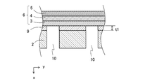
- the metal plate 2 may be a dense plate having a plurality of through holes 10 penetrating the metal plate 2 in the thickness direction.
- the through hole 10 may have a diameter of 0.01 mm or more and 1.0 mm or less in a cross section perpendicular to the thickness direction of the metal plate 2, for example.
- the dense metal plate 2 has a smaller surface area than the porous metal plate 2 and has higher corrosion resistance. Further, since the dense metal plate 2 has a small surface area, the oxide film formed on the surface, that is, the content of the oxide is small, and the dense metal plate 2 has higher conductivity.
- the shape of the metal plate 2 may be a flat plate having a pair of opposing planes, a first surface 2a and a second surface 2b. As shown in FIG. 4, the shape of the metal plate 2 may be a curved plate having a pair of opposing curved surfaces, a first surface 2a and a second surface 2b.
- the thickness of the metal plate 2 may be, for example, 100 ⁇ m or more and 1 mm or less.
- the material of the metal plate 2 may be, for example, a conductive material such as a heat-resistant alloy.
- the metal plate 2 contains Cr, and may contain, for example, 4 atomic% to 30 atomic% chromium (Cr) with respect to the entire alloy.
- the Cr-containing alloy may be a nickel-chromium alloy, an iron-chromium alloy, or an austenite-based, ferrite-based, or austenite-ferritic stainless steel.
- the metal plate 2 may contain manganese (Mn) and aluminum (Al) as elements other than Cr.
- the metal plate 2 and the first electrode layer 3 are often joined by heat treatment in an air atmosphere or a nitrogen atmosphere. This is because when the heat treatment is performed in a reducing atmosphere or in a vacuum, the first electrode layer 3 or the second electrode layer 5 is easily sintered and is difficult to be made porous. During this heat treatment, the surface of the alloy containing Cr is oxidized, and a passivation film of dichromium oxide (Cr 2 O 3 ) is formed on the surface of the alloy.
- the metal plate 2 has high corrosion resistance due to this passivation film.
- Cr 2 O 3 has low conductivity and increases the electrical resistance between the metal plate 2 and the first electrode layer 3 such as the fuel electrode.
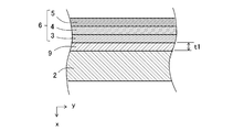
- the second chromium oxide (Cr 2 O 3 ) and Cr 2 O are formed between the first surface 2a of the metal plate 2 and the first electrode layer 3. It has a first intermediate layer 9 containing a first conductive particle different from 3 .
- the first intermediate layer 9 has conductivity.
- the first intermediate layer 9 may be a porous layer having, for example, 30% or more, particularly a porosity in the range of 35% to 50%.
- the first intermediate layer 9 may have a plurality of through holes 10 penetrating the first intermediate layer 9 in the thickness direction.
- the first intermediate layer 9 having a plurality of through holes 10 may be a dense layer.
- the first intermediate layer 9 is sandwiched between the first surface 2a of the metal plate 2 and the first electrode layer 3. When the metal plate 2 has the through hole 10, the through hole 10 also penetrates the first intermediate layer 9.
- the average thickness t1 of the first intermediate layer 9 may be, for example, 0.5 ⁇ m or more and 20 ⁇ m or less.
- the first intermediate layer 9 contains the second chromium oxide (Cr 2 O 3 ), the durability of the metal plate 2 can be enhanced even in a high temperature reaction atmosphere.
- Cr 2 O 3 is an insulator having an electrical resistivity of about 10 10 [Omega] m, when the first intermediate layer 9 which contains only Cr 2 O 3, between the metal plate 2 and the first electrode layer 3 The electrical resistance of the metal plate 2 becomes high, and it becomes difficult for the metal plate 2 to collect the electricity generated by the element unit 6.
- the first intermediate layer 9 comprises Cr 2 O 3, as containing different first conductive particles and further Cr 2 O 3, the conductivity of the first intermediate layer 9 is increased, the power generation by the element 6
- the generated electricity can be easily collected by the metal plate 2 through the first conductive particles different from Cr 2 O 3 .
- the first conductive particle different from Cr 2 O 3 is a particle having an electrical resistivity of about 10 ⁇ ⁇ m or less.
- the particle size of the first conductive particles which is different from Cr 2 O 3 , is smaller than the thickness t1 of the first intermediate layer 9.
- the particle size of the first conductive particle is, for example, smaller than 0.5 ⁇ m.
- the first conductive particles different from Cr 2 O 3 may be simply referred to as the first conductive particles.
- Cr 2 O 3 tends to have a small electric resistance due to the solid solution of other elements such as Ti and Mn.
- the movement of electrons in Cr 2 O 3 basically occurs when the electrons trapped in Cr atoms hop between the atoms.
- the amount of electrons that move by hopping is much smaller than the amount of free electrons that flow in metals and the like. Therefore, even if another element is dissolved in Cr 2 O 3 , it does not exhibit conductivity like a metal or the like.
- the electric resistance of Cr 2 O 3 fluctuates depending on the type and amount of the element that dissolves in solid solution and the surrounding atmosphere such as oxygen partial pressure, and stable characteristics cannot be obtained.
- the first intermediate layer 9 of the present disclosure contains first conductive particles different from Cr 2 O 3 .
- the electric resistance becomes smaller due to the conductivity of the first conductive particles themselves, and the first The contact between the conductive particles forms a current path in the intermediate layer 9, which facilitates the flow of current.
- the electric field strength applied to Cr 2 O 3 between the first conductive particles becomes large and the current easily flows. Therefore, the electrical resistance of the first intermediate layer 9 as a whole is smaller and the conductivity is higher when the first conductive particles are dispersed than when other elements are solid-solved in Cr 2 O 3. Become.
- the conductivity of the entire first intermediate layer 9 can be further enhanced.
- Cr 2 O 3 in the first intermediate layer 9 may have other elements such as Ti and Mn dissolved in a solid solution.
- the circumference of the first conductive particles may be covered with the first intermediate layer 9. That is, the first conductive particles may be inside the first intermediate layer 9 and may not be exposed from the first intermediate layer 9.
- the conductivity of the first conductive particles is different from that of the first conductive particles. Even if it fluctuates due to the difference in the contact atmosphere, the influence of the difference in the surrounding atmosphere of the first intermediate layer 9 on the first conductive particles becomes small. As a result, the conductivity of the first conductive particles is less likely to fluctuate.
- the difference in the surrounding atmosphere is, for example, the difference in the concentration of the fuel gas in contact with the first intermediate layer 9.
- the cell in which the metal plate 2 and the first electrode layer 3 are directly bonded is more than the cell 1 having an oxide film inactive layer or a first intermediate layer 9 between the metal plate 2 and the first electrode layer 3. ,
- the electrical resistance between the metal plate 2 and the first electrode layer 3 is low.
- the metal plate 2 since the metal plate 2 does not have a passivation layer, there is a concern that the corrosion resistance may be lowered.
- the first intermediate layer 9 oxidizes Cr 2 O 3, for example, 50 mol% or more, 95 mol% or less, and the first conductive particles, for example, with respect to the total amount of the elements contained in the first intermediate layer 9 converted into oxides. It may contain more than 5 mol% and less than 50 mol% in terms of material. Further, the first intermediate layer 9 may contain the first conductive particles in an amount of 3% by volume or more and 40% by volume or less. The method for measuring the composition of the first intermediate layer 9 will be described later.
- the first intermediate layer 9 may contain at least one element of manganese (Mn) and aluminum (Al) in addition to Cr 2 O 3 and the first conductive particles.
- Mn manganese
- Al aluminum
- Mn may form MnCr 2 O 4 , which is a spinel-type crystal which is a composite oxide of Cr and Mn.
- Mn and Al may be contained in the metal plate 2.
- the first conductive particles may be, for example, metal or alloy particles, conductive oxide particles, or the like.
- the first conductive particles may contain metals or alloys such as Ni, Cu, Co, Fe, and Ti. Metals or alloys such as Ni, Cu, Co, Fe, and Ti have an electrical resistivity of about 10-6 ⁇ m or less and show high conductivity.
- the first conductive particles may contain a lanthanum chromite-based perovskite-type oxide (LaCrO 3- based oxide) and a lanthanum strontium titanium-based perovskite-type oxide (LaSrTIO 3- based oxide).
- perovskite-type oxides have an electrical resistivity of about 10 ⁇ ⁇ m or less and exhibit conductivity, and even when they come into contact with a fuel gas such as a hydrogen-containing gas or an oxygen-containing gas such as air, the reduction is also oxidized. Not even.
- a fuel gas such as a hydrogen-containing gas or an oxygen-containing gas such as air
- These metals or alloys and perovskite-type oxides are stable even at high temperatures and have high conductivity, so that the electricity generated by the element unit 6 can be easily collected by the metal plate 2. ..
- metallic Ni not only has high conductivity, but also the conductivity does not easily fluctuate due to the difference in atmosphere. Therefore, the metallic Ni can maintain high conductivity even in a high temperature reaction atmosphere. Therefore, the metallic Ni can maintain stable conductivity even if the surrounding atmosphere, for example, the concentration of the fuel gas fluctuates.
- Ni is contained in the first electrode layer 3 which is a fuel electrode, and the first intermediate layer 9 contains the first conductive particles containing Ni, so that the first intermediate layer 9 and the first electrode layer 3 are contained. The bondability with can be improved.
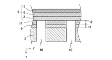
- the cell 1 may further have a porous second intermediate layer 11 between the first intermediate layer 9 and the first electrode layer 3.
- the second intermediate layer 11 also has gas permeability and conductivity.
- the second intermediate layer 11 may have an open porosity in the range of, for example, 30% or more, particularly 35% or more, and 50% or less.
- the through hole 10 may penetrate the second intermediate layer 11 in the thickness direction as shown in FIG. 6, or the second intermediate layer 11 may penetrate the second intermediate layer 11 as shown in FIG. It does not have to penetrate.
- the second intermediate layer 11 may be thicker than the first intermediate layer 9.
- the thickness t2 of the second intermediate layer 11 may be, for example, 10 ⁇ m or more and 200 ⁇ m or less. As shown in FIGS. 5 to 7, the thickness t2 of the second intermediate layer 11 is the thickness of the second intermediate layer 11 located between the first intermediate layer 9 and the first electrode layer 3. 1 It may be said that it is the distance between the intermediate layer 9 and the first electrode layer 3.
- the thickness t2 of the second intermediate layer 11 is larger than the thickness t1 of the first intermediate layer 9, Cr contained in the first intermediate layer 9 is less likely to diffuse into the first electrode layer 3.
- the second intermediate layer 11 When the second intermediate layer 11 has the above-mentioned open porosity, that is, an open porosity of 30% or more, the second intermediate layer 11 may be filled in at least a part of the through holes 10. That is, the thickness of the second intermediate layer 11 located above the through hole 10 shown in FIG. 7 may be larger than t2. The thickness of the second intermediate layer 11 located above the through hole 10 shown in FIG. 7 may be smaller than t2.
- the second intermediate layer 11 may contain the second conductive particles.
- the second conductive particles contained in the second intermediate layer 11 may be the above-mentioned metal or alloy particles, conductive oxide particles, or the like.
- the material of the second conductive particles contained in the second intermediate layer 11 may be the same as or different from that of the first conductive particles contained in the first intermediate layer 9 described above.
- the second conductive particles contained in the second intermediate layer 11 may contain a metal element having conductivity in a reduced state.
- the metal element having conductivity in the reduced state is, for example, Ni, Cu, Co, Zn and the like.
- the porous second intermediate layer 11 comes into contact with a fuel gas such as a reducing hydrogen-containing gas at a high temperature. Since the second intermediate layer 11 is porous and has a large surface area, the second conductive particles contained in the second intermediate layer 11 are easily reduced in a reducing atmosphere. Since the second conductive particles contained in the second intermediate layer 11 contain a metal element having conductivity in the reduced state, the second intermediate layer 11 can have high conductivity even in a reducing atmosphere, and the element. The electricity generated by the unit 6 can be easily collected by the metal plate 2.
- the first conductive particles contained in the porous first intermediate layer 9 may also contain a metal element having conductivity in a reduced state.
- the dense first intermediate layer 9 may contain an oxide as the first conductive particles. Since the dense first intermediate layer 9 has a small surface area, the first conductive particles of the oxide contained in the first intermediate layer 9 are less likely to be reduced in a reducing atmosphere.
- the second intermediate layer 11 may further contain an inorganic oxide.
- the inorganic oxide contained in the second intermediate layer 11 include oxides such as Ti, Zr, Al, Si, Mg, Ca, Sr and Ba, and rare earth oxides such as Y, Yb, Ce and Gd. Be done.
- the inorganic oxide contained in the second intermediate layer 11 may be, for example, stabilized zirconia, a rare earth oxide, an ABO 3 type perovskite type oxide, or titanium oxide. Note that the rare earth oxide comprises yttrium oxide (Y 2 O 3).
- the second intermediate layer 11 may contain stabilized zirconia or a rare earth oxide contained in the fuel electrode.
- the second intermediate layer 11 may contain a conductive ABO 3 type perovskite type oxide contained in the air electrode.
- the second intermediate layer 11 contains the same inorganic oxide as the inorganic oxide contained in the first electrode layer 3, the adhesive strength between the first electrode layer 3 and the metal plate 2 can be increased.
- the second intermediate layer 11 may contain at least one inorganic oxide of Ti, Al, and Si.
- the second intermediate layer 11 contains inorganic oxides of Ti, Al, and Si, the components of the second conductive particles contained in the second intermediate layer 11 are dissolved or diffused in the first intermediate layer 9. It becomes easier, the ratio of the first conductive particles contained in the first intermediate layer 9 becomes larger, and the conductivity of the first intermediate layer 9 can be made higher.
- the ratio of the second conductive particles to the total amount of the elements contained in the second intermediate layer 11 in terms of oxide is, for example, 40 mol. % Or more and 80 mol% or less, and the ratio of the inorganic oxide may be larger than, for example, 20 mol% and less than 60 mol%.
- the metal plate 2 may have a concave portion or a convex portion on at least one of the first surface 2a and the second surface 2b.
- FIG. 8 shows one of the examples of the cell 1 provided with the metal plate 2 having the recess on the first surface 2a.
- the upper view of FIG. 8 is a cross-sectional view of the cell 1, and the lower view is a plan view of the first surface 2a of the metal plate 2.
- the metal plate 2 when the metal plate 2 has a recess on the first surface 2a, the recess does not have to be in contact with the first electrode layer 3. That is, the metal plate 2 may have a gap between the recess of the first surface 2a and the first electrode layer 3.
- the gap between the recess on the first surface 2a and the first electrode layer 3 may be the gas flow path 7.
- the metal plate 2 also serves as the flow path member 8, and the metal plate 2 does not have to have gas permeability between the first surface 2a and the second surface 2b. ..
- FIG. 9 shows one of the examples of the cell 1 provided with the metal plate 2 having the convex portion on the first surface 2a.
- the upper view of FIG. 9 is a cross-sectional view of the cell 1, and the lower view is a plan view of the first surface 2a of the metal plate 2.
- the metal plate 2 when the metal plate 2 has a convex portion on the first surface 2a, only the convex portion may be in contact with the first electrode layer 3.
- Such a cell 1 has a gap between a portion other than the convex portion of the first surface 2a of the metal plate 2 and the first electrode layer 3, and this gap may be used as the gas flow path 7.
- the metal plate 2 also serves as the flow path member 8, and the metal plate 2 does not have to have gas permeability between the first surface 2a and the second surface 2b. ..
- the metal plate 2 may have irregularities on both the first surface 2a and the second surface 2b.
- the upper view of FIG. 10 is a cross-sectional view of the cell 1, and the lower view is a plan view of the first surface 2a of the metal plate 2.
- the convex portion of the first surface 2a may be in contact with the first electrode layer 3.
- Such a cell 1 has a gap between the recess of the first surface 2a of the metal plate 2 and the first electrode layer 3, and this gap may be used as the gas flow path 7.
- the metal plate 2 also serves as the flow path member 8, and the metal plate 2 does not have to have gas permeability between the first surface 2a and the second surface 2b. ..
- the cells 1 shown in FIGS. 8 to 10 also have the above-mentioned first intermediate layer 9 between the first surface 2a and the first electrode layer 3.
- Cell 1 shown in FIGS. 8 to 10 may further have a second intermediate layer 11.
- the presence or absence of the first intermediate layer 9 and the second intermediate layer 11 is determined by, for example, observing the cross section of the cell 1 with a scanning electron microscope (SEM), a scanning transmission electron microscope (STEM), a transmission electron microscope (TEM), or the like. You can check by doing.
- the elements contained in the first intermediate layer 9 and the second intermediate layer 11 and their content ratios are, for example, wavelength dispersive X-ray spectroscopy (WDS), energy dispersive X-ray spectroscopy (EDS), or electron probe microanalyzer (EPMA). It can be analyzed by. Elemental analysis results obtained, Cr 2 O 3, can be calculated first or second conductive particles, and the oxide-converted molar ratio of the inorganic oxide. Further, if necessary, the first intermediate layer 9 or the second intermediate layer 11 may be cut out from the cell 1 and elemental analysis such as high frequency inductively coupled plasma (ICP) emission spectroscopy may be performed.
- ICP inductively coupled plasma
- the volume ratio of the first conductive particles contained in the first intermediate layer 9 or the second conductive particles contained in the second intermediate layer 11 is the calculated Cr 2 O 3 , the first or second conductivity. It may be calculated based on the molar ratio of particles and inorganic oxides. Further, the volume ratio of the first conductive particles contained in the first intermediate layer 9 is determined by, for example, elemental mapping of the cross section of the first intermediate layer 9 to determine the area occupancy of the elements contained in the first conductive particles. It may be calculated by image analysis and converted into a volume ratio. Further, the element mapping image of the cross section of the second intermediate layer 11 may be image-analyzed to obtain the volume ratio of the second conductive particles contained in the second intermediate layer 11.
- Cell manufacturing method A method of manufacturing the cell 1 provided with the first intermediate layer 9 when the first electrode layer 3 is used as the fuel electrode will be described.
- a base material such as a stainless alloy containing Cr is prepared.
- the base material may be an alloy plate or an alloy foil.
- the base material may be an alloy plate or alloy foil having through holes 10, or a porous sintered body of metal powder.
- a laminate of a fuel electrode containing Ni and / or NiO and stabilized zirconia and stabilized zirconia to be the solid electrolyte layer 4 is prepared.
- the laminate of the fuel electrode and the solid electrolyte layer 4 may be produced by the following method.
- a binder is added to a slurry in which Ni or NiO powder and stabilized zirconia powder are mixed with an organic solvent to form a sheet to obtain a sheet-molded fuel electrode.
- a binder is added to a slurry in which a stabilized zirconia powder is mixed with an organic solvent, and the sheet is molded on a sheet molded body of a fuel electrode to obtain a laminated molded body.
- the obtained laminated molded body is fired to obtain a laminated body of the fuel electrode and the solid electrolyte layer 4.
- the base material and the fuel electrode that is, the laminate of the first electrode layer 3 and the solid electrolyte layer 4 are bonded with an adhesive.
- an adhesive at least one of conductive particles of Ni, NiO, Cu, Co and Zn, oxides such as Ti, Zr, Al, Si, Mg, Ca, Sr and Ba, and Y as inorganic oxides. , Yb, and other rare earth oxides, and a paste containing at least one of them is used.
- the adhesive may contain not only one type of conductive particles but also two or more types, and the adhesive material may contain not only one type but also two or more types of inorganic oxides. Further, the inorganic oxide may be a composite oxide of two or more kinds of elements.
- An adhesive is applied to the first surface 2a of the base material, and the first surface 2a to which the adhesive of the base material is applied is bonded to the surface of the first electrode layer 3 of the laminate.
- the bonded base material and the laminate are heat-treated in a nitrogen atmosphere or in the air, for example, in the range of 1000 ° C. to 1200 ° C. for 0.5 hours to 2 hours.
- a Cr 2 O 3 film in which first conductive particles such as Ni, Cu, Co, and Zn are dispersed is formed between the base material after the heat treatment and the first electrode layer 3.
- the oxides constituting the fuel electrode are reduced, and the particles of the material contained in the fuel electrode are easily grown. As a result, the sintering of the fuel electrode is promoted to form the fuel electrode. It may be difficult to react with the fuel gas, and the electrical resistance of the fuel electrode may increase.
- the second intermediate layer 11 may be formed between the base material and the first electrode layer 3 depending on the type of inorganic oxide contained in the adhesive, the coating thickness of the adhesive, the heat treatment conditions, and the like. In some cases, the constituent components of the adhesive diffuse into the base material or the first electrode layer 3, and a clear second intermediate layer 11 is not formed. For example, when the coating thickness of the adhesive is 10 ⁇ m or more, or when the heat treatment time is short, the constituent components of the adhesive do not diffuse to the base material or the first electrode layer 3 and easily remain at the interface, so that the second intermediate layer 11 is easily formed.
- the coating thickness of the adhesive is less than 1 ⁇ m, or when the heat treatment time is long, most of the constituent components of the adhesive are diffused to the base material or the first electrode layer 3 and hardly remain at the interface, which is clear. It is difficult for the second intermediate layer 11 to be formed.
- the adhesive contains titanium oxide (titania), the melting point of the adhesive is lowered, the adhesive is easily sintered, and the components of the conductive particles are solidly dissolved in the first intermediate layer 9 and the first electrode layer 3. It becomes easy to spread. Further, the Ti element can be dissolved in the chromium oxide of the first intermediate layer 9 to make the first intermediate layer 9 more conductive.
- titanium oxide titanium oxide
- the adhesive contains any of titania, aluminum oxide (alumina) and silicon oxide (silica), the coefficient of thermal expansion of the adhesive layer, that is, the second intermediate layer 11 becomes small.
- the first electrode layer 3 is a fuel electrode, the difference between the coefficient of thermal expansion of the second intermediate layer 11 and the coefficient of thermal expansion of the metal plate 2 and the coefficient of thermal expansion of the first electrode layer 3 becomes small, and the second The intermediate layer 11, the metal plate 2 and the first electrode layer 3 are less likely to be separated from each other.
- these inorganic oxides facilitate the movement of the components of the conductive particles contained in the adhesive to the chromium oxide layer which is the first intermediate layer 9 on the surface of the base material.
- Ni / NiO, titanium oxide (titania) and yttrium oxide react with yttrium oxide to dissolve Y 2 Ti 2 O 7 or NiO. 2 Form a composite oxide such as Ti 2 O 7 .
- the crystal phase of this composite oxide is stable to a reducing atmosphere, the crystal structure is unlikely to change depending on the atmosphere, and fracture due to volume change accompanying the phase transformation of the crystal is unlikely to occur.
- the cell 1 of the present disclosure can be obtained by forming an air electrode, which is the second electrode layer 5, on the surface of the solid electrolyte layer 4 of the base material and the laminate bonded by the adhesive.
- an air electrode for example, a binder is added to a slurry obtained by mixing a conductive ABO 3 type perovskite type oxide powder with an organic solvent, and after printing on the surface of the solid electrolyte layer 4, an oxidizing atmosphere is formed together with the base material and the laminate. It may be fired at 1000 ° C. to 1200 ° C.
- the laminate of the first electrode layer 3 and the solid electrolyte layer 4 was prepared in advance, and then the laminate was bonded to the substrate.
- the laminate of the first electrode layer 3 and the solid electrolyte layer 4 was formed.
- the first electrode layer 3 and the solid electrolyte layer 4 may be sequentially formed on the metal plate 2 without being prepared in advance.
- a sheet molded body to be the first electrode layer 3 may be attached to a metal plate 2 coated with an adhesive, and a sheet to be a solid electrolyte layer 4 may be further molded on the sheet molded body and then fired. ..
- the cell stack device 20 includes a cell stack 21 in which a plurality of cells 1 are arranged and a gas tank 22. The lower end of the cell 1 is joined and fixed to the opening of the gas tank 22.
- the gas tank 22 supplies fuel gas to a plurality of cells 1.
- the cell stack 21 includes a plurality of cells 1 arranged or stacked in the thickness direction of the cells 1 and a conductive member 23a for electrically connecting adjacent cells 1 in series.
- Cell 1 is cell 1 having the above-mentioned first intermediate layer 9.
- the direction in which a plurality of cells 1 are arranged is called the arrangement direction x.
- the conductive member 23a may also be arranged at both ends of the cell stack 21 in the arrangement direction x.
- the conductive member 23a may be joined to the cell 1 with a conductive adhesive.
- an elastic metal or alloy may be used, or a metal fiber or an alloy fiber felt may be used.
- the felt of the metal fiber or the alloy fiber may be surface-treated if necessary.
- the cell stack device 20 includes an end conductive member 23b outside the cell stack 21 in the arrangement direction x.
- the end conductive member 23b is electrically connected to the cell 1 located on the outermost side in the arrangement direction x.
- the end conductive member 23b has a drawer portion 23c that projects outward in the arrangement direction x.
- the drawing unit 23c collects the electricity generated by the cell 1 and draws it to the outside.
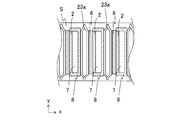
- FIG. 12 is an enlarged cross-sectional view of the broken line portion of FIG.
- the lower end of the cell 1 is fixed to the opening of the gas tank 22 with a sealing material S as shown in FIG.
- the gas flow path 7 of the cell 1 leads to a fuel gas chamber (not shown) of the gas tank 22.
- the material of the sealing material S may be, for example, glass having excellent heat resistance.
- the lower end of the conductive member 23a and the end conductive member 23b may be fixed to the gas tank 22 with the sealing material S.
- the end conductive member 23b may be integrated with the cell stack 21.
- FIG. 13 is an external perspective view showing one of the examples of the module including the cell stack device.
- the module 30 includes a rectangular parallelepiped storage container 31 and the above-mentioned cell stack device 20 housed inside the storage container 31.
- a reformer 32 is arranged above the cell stack 21.
- the reformer 32 is connected to the gas tank 22 by a gas flow pipe 33.
- the reformer 32 reforms raw fuels such as natural gas and kerosene supplied from the raw material fuel supply pipe 34 to generate fuel gas.
- the gas flow pipe 33 supplies the fuel gas reformed by the reformer 32 to the gas tank 22.
- the fuel gas is supplied from the gas tank 22 to the gas flow path 7 of the cell 1.
- FIG. 13 shows a state in which the front surface portion and the rear surface portion, which are a part of the storage container 31, are removed, and the cell stack device 20 housed inside the storage container 31 is taken out rearward.
- the module 30 shown in FIG. 13 can slide and contain the cell stack device 20 in the storage container 31.
- the cell stack device 20 does not have to include the reformer 32.
- the storage container 31 is provided with an oxygen-containing gas introduction member 35 inside.
- the oxygen-containing gas introduction member 35 of FIG. 13 is arranged between the two cell stacks 21 in a state where the cell stack device 20 is housed in the storage container 31.
- the oxygen-containing gas introduction member 35 supplies the oxygen-containing gas to the lower end of the cell 1.
- the oxygen-containing gas flows by the oxygen-containing gas introducing member 35 from the lower end to the upper end on the side of the cell 1 in accordance with the flow of the fuel gas.
- the fuel gas discharged from the gas flow path 7 of the cell 1 to the upper end of the cell 1 is mixed with the oxygen-containing gas and burned.
- the temperature of the cell 1 rises, and the start of the cell stack device 20 can be accelerated. Further, the combustion of the fuel gas at the upper end of the cell 1 warms the reformer 32 arranged above the cell 1, and the reformer 32 can efficiently perform the reforming reaction.
- FIG. 14 is an exploded perspective view showing an example of the module accommodating device. In FIG. 14, some configurations are omitted.
- the module accommodating device includes an outer case, a module housed in the outer case, and an auxiliary machine for operating the module.
- the module accommodating device 40 shown in FIG. 14 has a support column 41 and an exterior plate 42.
- the partition plate 43 divides the inside of the outer case into upper and lower parts.
- the space above the partition plate 43 in the outer case is the module accommodating chamber 44 for accommodating the module 30, and the space below the partition plate 43 in the outer case is the auxiliary accommodating the auxiliary machine for operating the module 30.
- the aircraft storage room 45 The description of the auxiliary equipment accommodated in the auxiliary equipment accommodation chamber 45 is omitted.
- the partition plate 43 has an air flow port 46 for flowing the air of the auxiliary machine accommodating chamber 45 to the module accommodating chamber 44 side.
- a part of the exterior plate 42 forming the module accommodating chamber 44 has an exhaust port 47 for exhausting the air in the module accommodating chamber 44. The air in the module accommodating chamber 44 is exhausted from the exhaust port 47.
- the module accommodating device 40 includes the above-mentioned module 30 in the module accommodating chamber 44, the module accommodating device 40 can be a module accommodating device 40 having high power generation efficiency.
- the fuel cell, the fuel cell stack device, the fuel cell module, and the fuel cell device are referred to as one of the examples of the "cell”, the “cell stack device”, the “module”, and the “module accommodating device”. Although shown, other examples may be an electrolytic cell, an electrolytic cell stack device, an electrolytic module, and an electrolytic device, respectively.
- the stainless steel alloy plate having a thickness of 0.3mm including Cr were prepared 81 pieces / cm 2 formed substrate through holes with a diameter of 0.3mm.
- a laminate of a fuel electrode, which is a mixture of NiO and stabilized zirconia, and a solid electrolyte layer of stabilized zirconia was prepared.
- the fuel electrode contains 60% by mass of NiO and 40% by mass of stabilized zirconia. Stabilization of the fuel electrode and the solid electrolyte layer of zirconia is contained 8 mol% of yttrium in the Y 2 O 3.
- the laminate was fired in the air at a maximum temperature of 1400 ° C. for 2 hours to integrate.
- a material to which TiO 2 powder and Y 2 O 3 powder were added instead of stabilized zirconia of the fuel electrode that is, a material A containing NiO, TiO 2 and Y 2 O 3 was prepared.
- a paste of material A was prepared and applied to the surface of a substrate which is a stainless alloy.
- the coating thickness of the adhesive was 50 ⁇ m.
- the electrical resistivity of the obtained bonded body was measured as follows. LaSrCoO 3 was baked onto the solid electrolyte layer to obtain an electrode having a diameter of 10 mm. A platinum mesh was attached to the surface of the base material facing the electrode, that is, the surface having no power generation element, and used as a counter electrode. The electrical resistivity was measured by the AC 4-terminal method.
- the electrical resistivity of the substrate heat-treated under the same conditions without applying an adhesive was measured.
- the electrical resistivity of the comparative example was 7.06 ⁇ ⁇ m
- the electrical resistivity of the entire intermediate layer including the first intermediate layer and the second intermediate layer of the joint using the material A was 0. It was 047 ⁇ ⁇ m.
- the cross section of the comparative example and the bonded body using the material A was confirmed by a scanning electron microscope (SEM). Elemental analysis of the cross section of each sample was performed using energy dispersive X-ray spectroscopy (EDS). In the reflected electron image of the SEM, a dense chromium oxide layer having a contrast different from that of metal is formed on the surface of the substrate of the comparative example, and the chromium oxide layer contains particles containing other elements, that is, the first conductivity. No sex particles were detected.
- a first intermediate layer containing chromium oxide and a first conductive particle containing Ni, and a porous Ni are provided between the base material and the fuel electrode. It had a second conductive particle containing and a second intermediate layer containing inorganic oxides such as zirconia, TiO 2 and Y 2 O 3 .
- the first intermediate layer of the bonded body using the material A had an average thickness of 6 ⁇ m and contained 80 mol% of chromium oxide and 20 mol% of Ni and Ti in terms of oxides.
- the second intermediate layer had an average thickness of 50 ⁇ m and an open porosity of 40%, and contained Ti and Y in an oxide equivalent of 30 mol% and Ni in an oxide equivalent of 70 mol%.
- Second intermediate layer 10 Through hole 11: Second intermediate layer 20: Cell stack device 21: Cell stack 22: Gas tank 30: Module 31: Storage container 32: Reformer 33: Gas flow pipe 40: Module storage device
Landscapes
- Chemical & Material Sciences (AREA)
- Life Sciences & Earth Sciences (AREA)
- Engineering & Computer Science (AREA)
- Manufacturing & Machinery (AREA)
- Sustainable Development (AREA)
- Sustainable Energy (AREA)
- Chemical Kinetics & Catalysis (AREA)
- Electrochemistry (AREA)
- General Chemical & Material Sciences (AREA)
- Fuel Cell (AREA)
- Composite Materials (AREA)
Abstract
Description
図1は金属支持体を備えたセルの横断面の例の1つを示している。セル1は、対向する一対の第1面2a及び第2面2bを有する金属板2及び流路部材8を有する金属支持体と、素子部6と、を備えている。素子部6は、金属板2の第1面上に配置され、第1電極層3、固体電解質層4、及び第2電極層5を有している。第1電極層3は金属板2の第1面上に配置され、固体電解質層4は第1電極層3上に配置されており、第2電極層5は固体電解質層4上に配置されている。
第1中間層9及び第2中間層11の有無は、例えば、セル1の横断面を走査型電子顕微鏡(SEM)、走査透過電子顕微鏡(STEM)、または透過型電子顕微鏡(TEM)などで観察することで確認できる。第1中間層9及び第2中間層11に含まれる元素及びその含有比率は、例えば波長分散型X線分光(WDS)、エネルギー分散型X線分光(EDS)、または電子線マイクロアナライザ(EPMA)などで分析できる。得られた元素分析結果から、Cr2O3、第1又は第2の導電性粒子、及び無機酸化物の酸化物換算したモル比率を算出することができる。また、必要に応じ、セル1から第1中間層9または第2中間層11を切り出し、高周波誘導結合プラズマ(ICP)発光分光などの元素分析を行ってもよい。
第1電極層3を燃料極とした場合の、第1中間層9を備えたセル1の製法について説明する。金属板2として、Crを含むステンレス合金等の基材を準備する。基材は、合金板または合金箔でもよい。ガス透過性を有する金属板2とする場合、基材は、貫通孔10を有する合金板または合金箔でもよいし、金属粉末の多孔質焼結体でもよい。また、Ni及び/またはNiOと安定化ジルコニアを含む燃料極と、固体電解質層4となる安定化ジルコニアとの積層体を準備する。
セルスタック装置20は、図11に示すように複数のセル1が配列されたセルスタック21とガスタンク22とを備えている。セル1の下端部は、ガスタンク22の開口部に接合され固定されている。ガスタンク22は、複数のセル1に燃料ガスを供給する。
図13は、セルスタック装置を備えるモジュールの例の1つを示す外観斜視図である。
図14は、モジュール収容装置の一例を示す分解斜視図である。なお、図14においては一部の構成を省略して示している。モジュール収容装置は、外装ケースと、外装ケース内に収容されたモジュール及びモジュールを運転する補機とを備えている。
2:金属板
3:第1電極層
4:固体電解質層
5:第2電極層
6:素子部
7:ガス流路
8:流路部材
9:第1中間層
10:貫通孔
11:第2中間層
20:セルスタック装置
21:セルスタック
22:ガスタンク
30:モジュール
31:収容容器
32:改質器
33:ガス流通管
40:モジュール収容装置
Claims (10)
- 対向する一対の第1面及び第2面を有し、Crを含有する金属板と、
前記第1面上に配置され、第1電極層、該第1電極層上に位置する固体電解質層、及び該固体電解質層上に位置する第2電極層を有する素子部と、
前記第1面と前記第1電極層との間に位置する第1中間層と、を備え、
該第1中間層は、Cr2O3及びCr2O3とは異なる第1の導電性粒子を含む、セル。 - 前記第1の導電性粒子の粒径が、前記第1中間層の厚さより小さい、請求項1に記載のセル。
- 前記第1の導電性粒子が、Niを含む、請求項1又は2に記載のセル。
- 前記第1中間層と前記第1電極層との間に、さらに、多孔質の第2中間層を有する、請求項1~3のいずれかに記載のセル。
- 前記第2中間層の厚さは、前記第1中間層よりも厚い、請求項4に記載のセル。
- 前記第2中間層が、第2の導電性粒子を含む、請求項4または5に記載のセル。
- 前記第2中間層が、さらに無機酸化物を含む、請求項6に記載のセル。
- 複数の請求項1~7のいずれかに記載のセルが配列されたセルスタックを備える、セルスタック装置。
- 収容容器と、該収容容器内に収容された請求項8に記載のセルスタック装置と、を備える、モジュール。
- 外装ケースと、該外装ケース内に収容された、請求項9に記載のモジュール及び該モジュールを運転する補機と、を備える、モジュール収容装置。
Priority Applications (4)
| Application Number | Priority Date | Filing Date | Title |
|---|---|---|---|
| JP2021516208A JP7250910B2 (ja) | 2019-04-24 | 2020-04-23 | セル、セルスタック装置、モジュール及びモジュール収容装置 |
| CN202080030493.7A CN113711402B (zh) | 2019-04-24 | 2020-04-23 | 单池、单池堆装置、模块及模块收纳装置 |
| US17/601,772 US12237553B2 (en) | 2019-04-24 | 2020-04-23 | Cell, cell stack device, module, and module housing device |
| EP20794119.6A EP3961777A4 (en) | 2019-04-24 | 2020-04-23 | CELL, CELL STACKING DEVICE, MODULE AND MODULE PACKAGE DEVICE |
Applications Claiming Priority (2)
| Application Number | Priority Date | Filing Date | Title |
|---|---|---|---|
| JP2019083010 | 2019-04-24 | ||
| JP2019-083010 | 2019-04-24 |
Publications (1)
| Publication Number | Publication Date |
|---|---|
| WO2020218431A1 true WO2020218431A1 (ja) | 2020-10-29 |
Family
ID=72942793
Family Applications (1)
| Application Number | Title | Priority Date | Filing Date |
|---|---|---|---|
| PCT/JP2020/017521 Ceased WO2020218431A1 (ja) | 2019-04-24 | 2020-04-23 | セル、セルスタック装置、モジュール及びモジュール収容装置 |
Country Status (5)
| Country | Link |
|---|---|
| US (1) | US12237553B2 (ja) |
| EP (1) | EP3961777A4 (ja) |
| JP (2) | JP7250910B2 (ja) |
| CN (1) | CN113711402B (ja) |
| WO (1) | WO2020218431A1 (ja) |
Cited By (14)
| Publication number | Priority date | Publication date | Assignee | Title |
|---|---|---|---|---|
| JP2021036499A (ja) * | 2019-08-30 | 2021-03-04 | 太陽誘電株式会社 | 固体酸化物型燃料電池およびその製造方法 |
| WO2023176979A1 (ja) * | 2022-03-18 | 2023-09-21 | 京セラ株式会社 | 電気化学セル、電気化学セル装置、モジュールおよびモジュール収容装置 |
| WO2023195520A1 (ja) * | 2022-04-08 | 2023-10-12 | 京セラ株式会社 | 電気化学セル、電気化学セル装置、モジュールおよびモジュール収容装置 |
| WO2024005210A1 (ja) | 2022-06-30 | 2024-01-04 | 京セラ株式会社 | 電気化学セル、電気化学セル装置、モジュールおよびモジュール収容装置 |
| JPWO2024048629A1 (ja) * | 2022-08-31 | 2024-03-07 | ||
| WO2024071093A1 (ja) * | 2022-09-29 | 2024-04-04 | 京セラ株式会社 | 導電部材、電気化学セル装置、モジュールおよびモジュール収容装置 |
| WO2024117052A1 (ja) * | 2022-11-30 | 2024-06-06 | 京セラ株式会社 | 複合部材、電気化学セル、電気化学セル装置、モジュールおよびモジュール収容装置 |
| WO2024143512A1 (ja) | 2022-12-27 | 2024-07-04 | 京セラ株式会社 | 電気化学セル、電気化学セル装置、モジュールおよびモジュール収容装置 |
| JPWO2024150829A1 (ja) * | 2023-01-13 | 2024-07-18 | ||
| US12107278B2 (en) | 2020-03-10 | 2024-10-01 | Taiyo Yuden Co., Ltd. | Solid oxide fuel cell and manufacturing method of the same |
| WO2025028530A1 (ja) * | 2023-07-31 | 2025-02-06 | 京セラ株式会社 | 電気化学セル、電気化学セル装置、モジュールおよびモジュール収容装置 |
| WO2025095015A1 (ja) * | 2023-10-30 | 2025-05-08 | 京セラ株式会社 | 電気化学セル、電気化学セル装置、モジュールおよびモジュール収容装置 |
| US12388091B2 (en) | 2019-10-07 | 2025-08-12 | Taiyo Yuden Co., Ltd. | Solid oxide fuel cell and manufacturing method of the same |
| JP7862602B2 (ja) | 2022-11-30 | 2026-05-19 | 京セラ株式会社 | 電気化学セル、電気化学セル装置、モジュールおよびモジュール収容装置 |
Families Citing this family (3)
| Publication number | Priority date | Publication date | Assignee | Title |
|---|---|---|---|---|
| WO2025183102A1 (ja) * | 2024-02-29 | 2025-09-04 | 京セラ株式会社 | 流路部材、電気化学セル、電気化学セル装置、モジュールおよびモジュール収容装置 |
| WO2025244917A1 (en) * | 2024-05-20 | 2025-11-27 | Precision Combustion, Inc. | Porous metal substrate for metal-supported electrochemical cell |
| JP2026006757A (ja) * | 2024-07-01 | 2026-01-16 | 株式会社デンソー | 固体酸化物形電解セル |
Citations (4)
| Publication number | Priority date | Publication date | Assignee | Title |
|---|---|---|---|---|
| JP2016115506A (ja) | 2014-12-15 | 2016-06-23 | 株式会社村田製作所 | メタルサポートsofc |
| JP2016195101A (ja) * | 2015-03-31 | 2016-11-17 | 大阪瓦斯株式会社 | 燃料電池用部材およびその製造方法 |
| WO2017022762A1 (ja) * | 2015-08-03 | 2017-02-09 | 本田技研工業株式会社 | メタルサポートセル |
| JP2018160368A (ja) * | 2017-03-22 | 2018-10-11 | 大阪瓦斯株式会社 | 金属支持型電気化学素子用の電極層付基板、電気化学素子、電気化学モジュール、電気化学装置、エネルギーシステム、固体酸化物形燃料電池、および製造方法 |
Family Cites Families (14)
| Publication number | Priority date | Publication date | Assignee | Title |
|---|---|---|---|---|
| JPH10172590A (ja) | 1996-12-12 | 1998-06-26 | Fuji Electric Corp Res & Dev Ltd | 固体電解質型燃料電池 |
| CN1075564C (zh) * | 1997-03-18 | 2001-11-28 | 住友特殊金属株式会社 | 低热膨胀合金 |
| JP4511122B2 (ja) * | 2003-02-28 | 2010-07-28 | 京セラ株式会社 | 燃料電池セル |
| JP4593997B2 (ja) * | 2004-07-28 | 2010-12-08 | 京セラ株式会社 | 燃料電池セル用支持体及び燃料電池セル並びに燃料電池 |
| JP5098186B2 (ja) * | 2006-02-20 | 2012-12-12 | 大日本印刷株式会社 | 色素増感型太陽電池の製造方法および色素増感型太陽電池 |
| TWI335305B (en) * | 2007-01-05 | 2011-01-01 | Univ Nat Taiwan Science Tech | The metallic bipolar plate of solid oxide fuel cell with perovskite protective coating and method of manufacturing thereof |
| US8993194B2 (en) * | 2009-10-28 | 2015-03-31 | Kyocera Corporation | Fuel cell, cell stack, fuel cell module, and fuel cell device |
| US20130004881A1 (en) * | 2010-03-15 | 2013-01-03 | Nima Shaigan | Composite coatings for oxidation protection |
| JP5712518B2 (ja) | 2010-07-16 | 2015-05-07 | 日産自動車株式会社 | 導電部材の製造方法 |
| JP5572146B2 (ja) * | 2011-03-22 | 2014-08-13 | 大阪瓦斯株式会社 | 保護膜形成方法、セル接続部材および固体酸化物形燃料電池用セル |
| CN105283994B (zh) * | 2013-06-27 | 2018-09-28 | 京瓷株式会社 | 电池单元、电池堆装置、模块以及模块收纳装置 |
| JP6204822B2 (ja) | 2013-12-24 | 2017-09-27 | 日本特殊陶業株式会社 | 固体酸化物形燃料電池 |
| US10014542B2 (en) * | 2014-10-29 | 2018-07-03 | Kyocera Corporation | Cell, cell stack device, module, and module storage device |
| JP6749050B2 (ja) | 2015-12-18 | 2020-09-02 | 京セラ株式会社 | セルスタック装置、モジュールおよびモジュール収容装置 |
-
2020
- 2020-04-23 JP JP2021516208A patent/JP7250910B2/ja active Active
- 2020-04-23 CN CN202080030493.7A patent/CN113711402B/zh active Active
- 2020-04-23 EP EP20794119.6A patent/EP3961777A4/en active Pending
- 2020-04-23 US US17/601,772 patent/US12237553B2/en active Active
- 2020-04-23 WO PCT/JP2020/017521 patent/WO2020218431A1/ja not_active Ceased
-
2023
- 2023-03-22 JP JP2023044959A patent/JP7645920B2/ja active Active
Patent Citations (4)
| Publication number | Priority date | Publication date | Assignee | Title |
|---|---|---|---|---|
| JP2016115506A (ja) | 2014-12-15 | 2016-06-23 | 株式会社村田製作所 | メタルサポートsofc |
| JP2016195101A (ja) * | 2015-03-31 | 2016-11-17 | 大阪瓦斯株式会社 | 燃料電池用部材およびその製造方法 |
| WO2017022762A1 (ja) * | 2015-08-03 | 2017-02-09 | 本田技研工業株式会社 | メタルサポートセル |
| JP2018160368A (ja) * | 2017-03-22 | 2018-10-11 | 大阪瓦斯株式会社 | 金属支持型電気化学素子用の電極層付基板、電気化学素子、電気化学モジュール、電気化学装置、エネルギーシステム、固体酸化物形燃料電池、および製造方法 |
Non-Patent Citations (1)
| Title |
|---|
| See also references of EP3961777A4 |
Cited By (23)
| Publication number | Priority date | Publication date | Assignee | Title |
|---|---|---|---|---|
| US11784317B2 (en) | 2019-08-30 | 2023-10-10 | Taiyo Yuden Co., Ltd. | Solid oxide fuel cell and manufacturing method of the same |
| JP7360276B2 (ja) | 2019-08-30 | 2023-10-12 | 太陽誘電株式会社 | 固体酸化物型燃料電池およびその製造方法 |
| JP2021036499A (ja) * | 2019-08-30 | 2021-03-04 | 太陽誘電株式会社 | 固体酸化物型燃料電池およびその製造方法 |
| US12388091B2 (en) | 2019-10-07 | 2025-08-12 | Taiyo Yuden Co., Ltd. | Solid oxide fuel cell and manufacturing method of the same |
| US12107278B2 (en) | 2020-03-10 | 2024-10-01 | Taiyo Yuden Co., Ltd. | Solid oxide fuel cell and manufacturing method of the same |
| WO2023176979A1 (ja) * | 2022-03-18 | 2023-09-21 | 京セラ株式会社 | 電気化学セル、電気化学セル装置、モジュールおよびモジュール収容装置 |
| JPWO2023176979A1 (ja) * | 2022-03-18 | 2023-09-21 | ||
| WO2023195520A1 (ja) * | 2022-04-08 | 2023-10-12 | 京セラ株式会社 | 電気化学セル、電気化学セル装置、モジュールおよびモジュール収容装置 |
| JPWO2023195520A1 (ja) * | 2022-04-08 | 2023-10-12 | ||
| WO2024005210A1 (ja) | 2022-06-30 | 2024-01-04 | 京セラ株式会社 | 電気化学セル、電気化学セル装置、モジュールおよびモジュール収容装置 |
| JPWO2024048629A1 (ja) * | 2022-08-31 | 2024-03-07 | ||
| WO2024048629A1 (ja) * | 2022-08-31 | 2024-03-07 | 京セラ株式会社 | 電気化学セル装置、モジュールおよびモジュール収容装置 |
| WO2024071093A1 (ja) * | 2022-09-29 | 2024-04-04 | 京セラ株式会社 | 導電部材、電気化学セル装置、モジュールおよびモジュール収容装置 |
| JP7543601B1 (ja) * | 2022-09-29 | 2024-09-02 | 京セラ株式会社 | 導電部材、電気化学セル装置、モジュールおよびモジュール収容装置 |
| JPWO2024117052A1 (ja) * | 2022-11-30 | 2024-06-06 | ||
| WO2024117052A1 (ja) * | 2022-11-30 | 2024-06-06 | 京セラ株式会社 | 複合部材、電気化学セル、電気化学セル装置、モジュールおよびモジュール収容装置 |
| JP7862602B2 (ja) | 2022-11-30 | 2026-05-19 | 京セラ株式会社 | 電気化学セル、電気化学セル装置、モジュールおよびモジュール収容装置 |
| WO2024143512A1 (ja) | 2022-12-27 | 2024-07-04 | 京セラ株式会社 | 電気化学セル、電気化学セル装置、モジュールおよびモジュール収容装置 |
| EP4621891A1 (en) | 2022-12-27 | 2025-09-24 | Kyocera Corporation | Electrochemical cell, electrochemical cell device, module, and module-accommodating device |
| JPWO2024150829A1 (ja) * | 2023-01-13 | 2024-07-18 | ||
| WO2024150829A1 (ja) * | 2023-01-13 | 2024-07-18 | 京セラ株式会社 | 電気化学セル、電気化学セル装置、モジュールおよびモジュール収容装置 |
| WO2025028530A1 (ja) * | 2023-07-31 | 2025-02-06 | 京セラ株式会社 | 電気化学セル、電気化学セル装置、モジュールおよびモジュール収容装置 |
| WO2025095015A1 (ja) * | 2023-10-30 | 2025-05-08 | 京セラ株式会社 | 電気化学セル、電気化学セル装置、モジュールおよびモジュール収容装置 |
Also Published As
| Publication number | Publication date |
|---|---|
| CN113711402B (zh) | 2024-10-29 |
| JP2023093447A (ja) | 2023-07-04 |
| JP7250910B2 (ja) | 2023-04-03 |
| EP3961777A1 (en) | 2022-03-02 |
| US12237553B2 (en) | 2025-02-25 |
| EP3961777A4 (en) | 2023-09-20 |
| US20220200033A1 (en) | 2022-06-23 |
| JPWO2020218431A1 (ja) | 2020-10-29 |
| CN113711402A (zh) | 2021-11-26 |
| JP7645920B2 (ja) | 2025-03-14 |
Similar Documents
| Publication | Publication Date | Title |
|---|---|---|
| JP7645920B2 (ja) | セル、セルスタック装置、モジュール及びモジュール収容装置 | |
| EP2393148B1 (en) | Heat-resistant alloy, alloy member for fuel cell, fuel cell stack device, fuel cell module, and fuel cell device | |
| JP6882614B2 (ja) | セル、セルスタック装置、モジュール及びモジュール収容装置 | |
| TW201900898A (zh) | 電化學元件、電化學模組、電化學裝置、能源系統、固態氧化物型燃料電池、及電化學元件之製造方法 | |
| KR20120047305A (ko) | 연료전지 셀, 셀 스택, 연료전지 모듈, 및 연료전지 장치 | |
| JP5744348B1 (ja) | セル、セルスタック装置、モジュールおよびモジュール収容装置 | |
| CN108463913B (zh) | 导电构件、单体堆、模块及模块收容装置 | |
| CN103946422A (zh) | 复合体、集电构件和燃料电池单元装置以及燃料电池装置 | |
| JP6383003B2 (ja) | 導電部材、セルスタック装置、モジュール、モジュール収納装置および導電部材の製造方法 | |
| KR102564764B1 (ko) | 전기 화학 장치, 에너지 시스템, 및 고체 산화물형 연료 전지 | |
| WO2019240297A1 (ja) | セル、セルスタック装置、モジュール及びモジュール収納装置 | |
| JP5289010B2 (ja) | 固体酸化物形燃料電池セル、燃料電池セルスタック装置、燃料電池モジュールおよび燃料電池装置 | |
| JP6818960B1 (ja) | セル、セルスタック装置、モジュールおよびモジュール収容装置 | |
| JP2006079831A (ja) | 燃料電池セル及びセルスタック | |
| JPWO2020111124A1 (ja) | セル、セルスタック装置、モジュール、及びモジュール収納装置 | |
| JP4557578B2 (ja) | 燃料電池セル及びセルスタック並びに燃料電池 | |
| CN119895596A (zh) | 导电构件、电化学电池装置、组件以及组件收容装置 |
Legal Events
| Date | Code | Title | Description |
|---|---|---|---|
| 121 | Ep: the epo has been informed by wipo that ep was designated in this application |
Ref document number: 20794119 Country of ref document: EP Kind code of ref document: A1 |
|
| ENP | Entry into the national phase |
Ref document number: 2021516208 Country of ref document: JP Kind code of ref document: A |
|
| NENP | Non-entry into the national phase |
Ref country code: DE |
|
| ENP | Entry into the national phase |
Ref document number: 2020794119 Country of ref document: EP Effective date: 20211124 |
|
| WWG | Wipo information: grant in national office |
Ref document number: 17601772 Country of ref document: US |