WO2020230250A1 - コントローラ - Google Patents
コントローラ Download PDFInfo
- Publication number
- WO2020230250A1 WO2020230250A1 PCT/JP2019/018993 JP2019018993W WO2020230250A1 WO 2020230250 A1 WO2020230250 A1 WO 2020230250A1 JP 2019018993 W JP2019018993 W JP 2019018993W WO 2020230250 A1 WO2020230250 A1 WO 2020230250A1
- Authority
- WO
- WIPO (PCT)
- Prior art keywords
- suction
- suction pad
- deformation
- unit
- control unit
- Prior art date
- Legal status (The legal status is an assumption and is not a legal conclusion. Google has not performed a legal analysis and makes no representation as to the accuracy of the status listed.)
- Ceased
Links
Images


Classifications
-
- B—PERFORMING OPERATIONS; TRANSPORTING
- B25—HAND TOOLS; PORTABLE POWER-DRIVEN TOOLS; MANIPULATORS
- B25J—MANIPULATORS; CHAMBERS PROVIDED WITH MANIPULATION DEVICES
- B25J13/00—Controls for manipulators
- B25J13/08—Controls for manipulators by means of sensing devices, e.g. viewing or touching devices
-
- B—PERFORMING OPERATIONS; TRANSPORTING
- B65—CONVEYING; PACKING; STORING; HANDLING THIN OR FILAMENTARY MATERIAL
- B65G—TRANSPORT OR STORAGE DEVICES, e.g. CONVEYORS FOR LOADING OR TIPPING, SHOP CONVEYOR SYSTEMS OR PNEUMATIC TUBE CONVEYORS
- B65G47/00—Article or material-handling devices associated with conveyors; Methods employing such devices
- B65G47/74—Feeding, transfer, or discharging devices of particular kinds or types
- B65G47/90—Devices for picking-up and depositing articles or materials
- B65G47/91—Devices for picking-up and depositing articles or materials incorporating pneumatic, e.g. suction, grippers
- B65G47/917—Devices for picking-up and depositing articles or materials incorporating pneumatic, e.g. suction, grippers control arrangements
-
- B—PERFORMING OPERATIONS; TRANSPORTING
- B25—HAND TOOLS; PORTABLE POWER-DRIVEN TOOLS; MANIPULATORS
- B25J—MANIPULATORS; CHAMBERS PROVIDED WITH MANIPULATION DEVICES
- B25J15/00—Gripping heads and other end effectors
- B25J15/06—Gripping heads and other end effectors with vacuum or magnetic holding means
- B25J15/0616—Gripping heads and other end effectors with vacuum or magnetic holding means with vacuum
-
- B—PERFORMING OPERATIONS; TRANSPORTING
- B25—HAND TOOLS; PORTABLE POWER-DRIVEN TOOLS; MANIPULATORS
- B25J—MANIPULATORS; CHAMBERS PROVIDED WITH MANIPULATION DEVICES
- B25J5/00—Manipulators mounted on wheels or on carriages
- B25J5/007—Manipulators mounted on wheels or on carriages mounted on wheels
-
- B—PERFORMING OPERATIONS; TRANSPORTING
- B25—HAND TOOLS; PORTABLE POWER-DRIVEN TOOLS; MANIPULATORS
- B25J—MANIPULATORS; CHAMBERS PROVIDED WITH MANIPULATION DEVICES
- B25J9/00—Program-controlled manipulators
- B25J9/16—Program controls
- B25J9/1612—Program controls characterised by the hand, wrist, grip control
-
- G—PHYSICS
- G05—CONTROLLING; REGULATING
- G05B—CONTROL OR REGULATING SYSTEMS IN GENERAL; FUNCTIONAL ELEMENTS OF SUCH SYSTEMS; MONITORING OR TESTING ARRANGEMENTS FOR SUCH SYSTEMS OR ELEMENTS
- G05B2219/00—Program-control systems
- G05B2219/30—Nc systems
- G05B2219/39—Robotics, robotics to robotics hand
- G05B2219/39175—Cooperation between fixed manipulator and manipulator on vehicle
-
- G—PHYSICS
- G05—CONTROLLING; REGULATING
- G05B—CONTROL OR REGULATING SYSTEMS IN GENERAL; FUNCTIONAL ELEMENTS OF SUCH SYSTEMS; MONITORING OR TESTING ARRANGEMENTS FOR SUCH SYSTEMS OR ELEMENTS
- G05B2219/00—Program-control systems
- G05B2219/30—Nc systems
- G05B2219/39—Robotics, robotics to robotics hand
- G05B2219/39529—Force, torque sensor in wrist, end effector
Definitions
- the present invention relates to a controller such as a transfer robot arm.
- a robot arm equipped with a suction pad is known as a transfer robot.
- a negative pressure is generated on the suction pad, and a work or the like, which is an object to be transported, is sucked on the suction pad for picking.
- the generation of negative pressure is stopped to release the adsorption.
- a sensor is installed near the suction part, and the position of the object before the suction pad comes into contact with the object. -The posture is detected and the movement of the suction part is controlled based on the detection result.
- the sensor installed near the suction pad detects the posture of the target object before the suction portion comes into contact with the target object. Therefore, the detection of the position and orientation of the object is easily affected by the disturbance environment (light, vibration, electrical noise) and the material, material, color, etc. of the object due to the characteristics of the sensor, and the attitude of the suction part is highly accurate. Was difficult to control.
- One aspect of the present invention is aimed at realizing a technique capable of appropriately controlling the movement of the suction pad.
- the controller includes a deformation information acquisition unit that attracts an object by a negative pressure and acquires deformation information of the suction unit that is deformed by the negative pressure. It is provided with an operation control unit that controls the movement of the suction unit according to the deformation of the suction unit.
- the posture of the object can be detected by detecting the deformation of the suction portion after contacting the object, so that advanced posture correction is possible without being affected by the disturbance environment.
- a controller can be realized.
- the operation control unit may change the inclination of the suction unit according to the deformation of the suction unit.
- the motion control unit may change the inclination of the suction unit so as to reduce the angle formed by the suction surface of the suction unit and the suction surface of the object. Good.
- the angle formed by the suction surface of the suction part and the suction surface of the object can be detected from the deformation of the suction part, so that a controller capable of advanced posture correction can be realized. ..
- the motion control unit includes a contact point specifying unit that specifies a contact point of the suction unit with the object based on the deformation of the suction unit, and the motion control unit. May change the inclination of the suction portion while maintaining the contact between the suction portion and the object at the contact point.
- the suction portion and the object can be completely brought into close contact with each other by changing the inclination of the suction portion while maintaining the contact between the suction portion and the object at the contact point. As a result, it is possible to prevent picking mistakes of the object by the suction portion.
- the operation control unit may rotate the suction unit in a plane including the central axis of the suction surface of the suction unit and the contact point.
- the suction portion and the object can be completely brought into close contact with each other by changing the inclination of the suction portion while maintaining the contact between the suction portion and the object at the contact point. As a result, it is possible to prevent picking mistakes of the object by the suction portion.
- the motion control unit in a state where the suction unit is sucking the object, the motion control unit has a surface that is not the surface to be sucked and the surface to be arranged.
- the inclination of the suction portion may be changed so as to reduce the angle formed by the suction portion.
- the posture of the suction portion after a part of the object comes into contact with the surface to be placed can be detected, so that the object can be placed with high accuracy. It can be placed on the surface to be placed.
- the motion control unit contacts the object to be arranged on the object based on the deformation of the suction unit in a state where the suction unit is sucking the object.
- the operation control unit may change the inclination of the suction unit while maintaining the contact between the object and the arrangement target surface at the contact point, which includes the contact point specifying unit for specifying the point.
- the posture of the suction portion after a part of the object comes into contact with the surface to be placed can be detected, so that the object can be placed with high accuracy. It can be placed on the surface to be placed.
- the operation control unit may change the speed of the suction unit according to the deformation of the suction unit.
- the operation control unit may reduce the speed at which the suction unit is brought closer to the object when the deformation amount of the suction unit exceeds the first threshold value.
- the speed of the suction part after the partial contact can be reduced, and high-precision correction can be performed. , The risk of damaging the object can be prevented.
- the operation control unit may stop the operation of bringing the suction unit closer to the object when the deformation amount of the suction unit exceeds the second threshold value.
- the deformation information acquisition unit acquires the deformation amount and / or the deformation speed of the suction unit
- the operation control unit obtains the deformation amount and / or the deformation of the suction unit.
- the movement of the suction portion may be controlled according to the speed.
- the movement of the suction portion can be controlled with high accuracy by controlling the movement of the suction portion based on the deformation amount and / or the deformation speed of the suction portion.
- control method is a control method of an adsorption device including an adsorption portion that adsorbs an object by a negative pressure and deforms by the negative pressure. It includes a deformation information acquisition step of acquiring information on the deformation of the portion, and an operation control step of controlling the movement of the suction portion according to the deformation of the suction portion.
- the amount of deformation of the suction portion after contact with the object can be detected, and the posture of the suction portion can be corrected based on the amount of deformation of the suction portion, which is affected by the disturbance environment. It is possible to provide a controller capable of controlling the movement of the suction portion with high accuracy.
- FIG. 1 It is a block diagram which shows an example of the schematic structure of the suction device including the controller 5 which concerns on a modification. It is a flowchart which shows the operation of the suction device which includes the controller 5 which concerns on a modification. It is a schematic diagram which shows an example of the processing flow of the suction device which includes the controller 5 which concerns on a modification.
- FIG. 1 schematically illustrates an example of an application situation of the controller 5 according to the present embodiment.
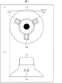
- FIG. 2 schematically illustrates an example of a suction pad (suction unit) 112 and a deformation information acquisition unit 113 in the mobile suction device 100 equipped with the controller 5 according to the present embodiment.
- FIG. 2A schematically illustrates an example of a top view of the suction pad 112 and the deformation information acquisition unit 113.
- FIG. 2B schematically illustrates an example of a side view of the suction pad 112 and the deformation information acquisition unit 113.
- the mobile suction device 100 includes a suction device 1 and a transport unit (automated guided vehicle) 2.
- the suction device 1 includes a robot arm 11, a vacuum pump 12, and a manipulator control unit 13.
- the transport unit 2 moves (conveys) the mobile suction device 100.
- the transport unit 2 includes a negative pressure control unit 21 that controls a vacuum pump that generates a negative pressure (air pressure), and an automatic guided vehicle 22.
- the mobile suction device 100 is not particularly limited as long as it includes a suction device 1 including a suction pad 112 that is deformed by a negative pressure, and an example thereof includes a vacuum suction system such as a mobile robot. Further, the suction device 1 can be applied not only to the mobile suction device 100 such as a mobile robot but also to a fixed suction device.
- the robot arm 11 performs a gripping operation by adsorbing an object by a negative pressure.
- the robot arm 11 includes a manipulator unit 111 that grips the object by attracting the object to the suction pad 112, and a suction pad 112.
- An example of the suction pad 112 is a suction pad (vacuum pad) provided with a suction cup.
- the object can be suitably sucked and gripped.
- the object may be gripped by being attracted to the robot arm 11 by a negative pressure, and examples thereof include a work.
- the suction pad 112 may be provided with (or may be attached to) a deformation information acquisition unit 113 that detects (detects) the deformation of the suction pad 112.
- the deformation information acquisition unit 113 may include a strain sensor (strain gauge) 114 arranged on the suction pad 112. Examples include gauge terminals for strain measurement.
- the deformation information acquisition unit 113 may include one strain sensor 114, but may include a plurality of (for example, three) strain sensors 114a, 114b and 114c as shown in the example of FIG.
- the deformation information acquisition unit 113 detects deformation at a plurality of locations on the suction pad 112 (for example, at least one of the deformation amount and the deformation speed (differentiation of the deformation amount) of the suction pad 112). Thereby, the deformation of the suction pad 112 can be detected more preferably.
- FIG. 4 is a schematic view showing a scene in which a suction pad 112 picks one work W from a plurality of objects (work) arranged on a table.
- FIG. 4A shows a state of picking in a conventional example
- FIG. 4B shows a state of picking in one aspect of the present invention.
- the controller of the transfer robot lowers the robot arm including the suction pad 112 in the vertical direction to bring the suction pad 112 closer to the work W placed on the table. Then, when the suction surface of the suction pad 112 and the suction surface of the work W come into contact with each other on the entire surface, the suction surface of the work W is sucked by the negative pressure of the suction pad 112, and the suction surface of the suction pad 112 and the work W are covered. Adhere the suction surface.
- the controller controls the robot arm to lift the work W and convey the work W to a desired location while the work W is being sucked on the suction pad 112.
- the controller has acquired the position information (foresight information) of the suctioned surface S1 (indicated by the dotted line) of the work W placed on the table in advance. Based on this foresight information, the controller controls the suction pad 112 so that the suction surface of the suction pad 112 is brought into close contact with the suction surface of the work W in parallel.
- the foresight information (position information and attitude information of the suctioned surface S1 of the work W) obtained from an image or the like taken by a camera often includes an error.
- the position information is information with three degrees of freedom including not only the position information in the plane direction but also the position information in the vertical direction.
- the posture information is information indicating the inclination of the surface to be attracted S1.
- the position and orientation of the suctioned surface S1 of the work W indicated by the foresight information may not match the position and orientation of the actual suctioned surface S2 of the work W. For example, in the scene shown in FIG. 4A, the left side of the work W overlaps with an adjacent object and is placed in a state of being lifted from a table.
- the surface to be attracted to the actual work W is located at S2 shown by the solid line in FIG. 4A. Therefore, even if the controller tries to suck the work W based only on the foresight information, the suction surface of the suction pad 112 and the actual suction surface S2 do not match, and the suction surface of the suction pad 112 and the suction surface of the work W are attracted. Does not touch as a whole. Therefore, even if the suction pad 112 is controlled to suck the work W in the above state, air leaks at the portion where the right side of the work W and the suction pad 112 are not in contact with each other, and the suction pad 112 is normally used. Work W cannot be picked. As a result, picking mistakes occur.
- the controller 5 of the present embodiment after the suction pad 112 is brought closer to the work W based on the foresight information, the movement of the suction pad 112 is controlled according to the deformation of the suction pad 112.
- FIG. 4B a part of the suction pad 112 is deformed when the suction pad 112 and the surface to be sucked by the work W come into contact with each other at the contact point C.
- the controller 5 identifies the position of the contact point C based on the deformation of the suction pad 112.
- the controller 5 changes the inclination of the suction pad 112 while maintaining the contact between the suction pad 112 and the work W at the contact point C. That is, the controller 5 changes the inclination of the suction pad 112 so as to reduce the angle formed by the suction surface of the suction pad 112 and the suction surface of the work W with the contact point C as a fulcrum.
- the deformation of the suction pad 112 becomes uniform (the angle formed by the suction surface of the suction pad 112 and the suction surface of the work W becomes 0), and the suction surface of the suction pad 112 and the work W cover.
- the suction pad 112 sucks the work W and controls it to pick it.
- the controller 5 of the present embodiment when the controller 5 of the present embodiment is applied to the transfer robot and the suction pad 112 attached to the tip of the robot arm picks the object placed on the table, the suction pad 112
- the controller 5 identifies the position of the contact point C after the robot contacts the object at one point on the surface to be attracted. After that, the controller 5 controls the movement of the suction pad 112 so that the suction surface of the suction pad 112 and the suction surface of the object are in close contact with each other while maintaining the contact at the contact point C, and the suction pad 112 is targeted. Adsorb things. Therefore, the object can be picked reliably, and the risk of damaging the object due to a picking error can be prevented.
- FIG. 5 shows a scene in which the suction pad 112 is pushed against the work W placed on the table.
- FIG. 5A shows a state of pushing in a conventional example
- FIG. 5B shows a state of pushing in an application example of the present invention.
- the controller of the transfer robot lowers the robot arm including the suction pad 112 in the vertical direction to bring the suction pad 112 closer to the work W placed on the table, and applies an appropriate pressure. Push in the upper surface of the work W. After that, the controller stops the descent of the suction pad 112.
- the controller the position information and the posture information (foresight information) of the upper surface S1 of the work W normally placed on the table are stored in advance. Based on this foresight information, the controller brings the suction pad 112 closer to the upper surface of the work W and pushes the suction pad 112 into the work W at an appropriate distance.
- the upper surface S2 of the actual work W may be lower than S1 as shown on the left in FIG. 5 (a) or higher than S1 as shown on the right in FIG. 5 (a). Therefore, in the configuration in which the controller controls the suction pad 112 based only on the foresight information, as shown on the left side of FIG. 5A, when the upper surface S2 of the actual work W is lower than S1, the suction pad 112 The suction of the suction pad 112 is started in a state where the work W is not sufficiently pushed. Therefore, the amount of pushing (pushing distance) becomes insufficient, and picking of the work W fails. On the contrary, as shown on the right side of FIG.
- the suction pad 112 when the suction pad 112 is brought close to the work W, the suction pad 112 is sucked while observing the pushing amount of the suction pad 112 against the work W. Correct the position and orientation of the pad 112. Therefore, the amount of the suction pad 112 pushed into the work W can be kept constant.
- FIG. 6 shows a scene in which a work W in a state of being attracted to a robot arm is placed (placed) on a table.
- FIG. 6A shows the state of the place in the conventional example
- FIG. 6B shows the state of the place in the application example of the present invention.
- the controller lowers the robot arm in a state where the work W is sucked by the suction pad 112 in the vertical direction to bring the work W closer to the table. Then, the suction of the suction pad 112 is released, and the work W is placed on the surface to be arranged on the table.
- the controller has previously acquired the position S1 of the surface to be arranged on the table as foresight information. Based on this foresight information, the controller of the conventional example determines that the bottom surface of the work W has reached the position S1 and the work W and the surface to be arranged on the table are in contact with each other as a whole. Therefore, the controller controls to release the suction of the suction pad 112 and place the work W on the table.
- the position S1 of the placement target surface based on the foresight information does not match the position S2 of the actual placement target surface.
- the suction pad 112 is released from suction and the work W is placed when the bottom surface of the work W reaches the position S1, the work W is not placed at the correct position.
- the work W may be damaged as a result of falling to the position S2 of the actual placement target surface.
- the robot arm may continue to descend. In this way, the work W and / or the suction pad 112 may be damaged.
- the posture of the suction pad 112 is corrected based on the deformation of the suction pad 112.
- the suction pad 112 is deformed when the work W comes into contact with the surface to be arranged on the table at the contact point C'.
- the controller 5 identifies the position of the contact point C'based on the deformation of the suction pad 112.
- the controller 5 detects that the lower surface of the work W and the surface to be arranged on the table are not in contact with each other as a whole.
- the controller 5 changes the inclination of the suction pad 112 so as to reduce the angle formed by the surface (that is, the lower surface) of the suctioned work W that is not the surface to be attracted and the surface to be arranged on the table. That is, the controller 5 uses the contact point C'as a fulcrum to reduce the angle formed by the suction surface of the suction pad 112 and the placement target surface of the table, that is, the bottom surface of the work W and the placement target surface of the table. The inclination of the suction pad 112 is changed so as to reduce the angle.
- the controller 5 has information such as the shape and size of the work W.
- the controller 5 of the present embodiment when the work W adsorbed on the suction pad 112 is placed on the surface to be arranged on the table, the lower surface of the work W is one point on the surface to be arranged on the table. After contacting with, the position of the contact point C'is specified, and the movement of the suction pad 112 is controlled so that the lower surface of the work W and the surface to be arranged on the table are in close contact with each other while maintaining the contact at the contact point C'. After that, the suction of the work W is released. Therefore, the work W can be placed at an appropriate position, and it is possible to prevent the object from being damaged due to a place mistake.
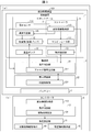
- FIG. 3 is a block diagram schematically illustrating an example of the configuration of the mobile suction device 100 according to the present embodiment.
- the mobile suction device 100 according to the present embodiment includes a suction device 1, a transport unit 2, and a battery 3.
- the suction device 1 includes a robot arm 11, a vacuum pump 12, and an operation control unit (manipulator control unit) 13.
- the robot arm 11 includes a manipulator unit 111, a suction pad 112, a deformation information acquisition unit 113, and an operation control unit.
- the manipulator unit 111 is driven together with the suction pad 112 in the robot arm 11 under the control of the motion control unit 13.
- the manipulator unit 111 has, for example, one or more joints.
- suction pad 112 When the suction pad 112 is positioned at the working position by driving the manipulator unit 111, the suction pad 112 sucks the target object by a negative pressure corresponding to the driving amount of the vacuum pump 12 to perform a gripping operation of the target object.
- the deformation information acquisition unit 113 acquires information on the deformation of the suction pad 112. For example, the deformation information acquisition unit 113 acquires data indicating the strain of the suction pad 112 from the strain sensor 114. The deformation information acquisition unit 113 specifies the amount of deformation of the suction pad 112 from the data indicating the strain. A specific example of the amount of deformation will be described later.
- the deformation information acquisition unit 113 may acquire information on deformation at a plurality of locations on the suction pad 112 from the plurality of strain sensors 114a, 114b, and 114c.
- the deformation information acquisition unit 113 is not particularly limited as long as it can acquire the deformation information of the suction pad 112.
- the deformation information acquisition unit 113 may acquire deformation information from, for example, one or more sensors arranged or built in the suction pad 112. Since the sensor is arranged or built in the suction pad 112, the deformation of the suction pad 112 can be suitably detected. When the sensor is built in the suction pad 112, as shown in the example of FIG.
- the sensor can be built in the suction pad 112 corresponding to the position of the suction pad 112 where the strain sensor 114 is arranged.
- the sensor built in the suction pad 112 include a strain gauge type sensor and a pressure-sensitive conductive sensor made of rubber or resin containing a conductor material such as carbon nanotubes and carbon particles.
- the deformation information acquisition unit 113 may acquire deformation information from one or more optical displacement sensors (distance sensors such as a laser displacement sensor) or shape measurement sensors instead of the distortion sensor 114.
- one or more optical displacement meters or shape measurement sensors are arranged on the suction pad 112 like the strain sensor 114.
- the optical displacement meter or the shape measurement sensor detects the light reflected by the suction pad 112 and measures the displacement amount of the suction pad 112 to measure the displacement amount of the suction pad 112. Deformation can be suitably detected (shape change can be measured).
- the suction pad 112 Even when one two-dimensional shape measurement sensor is arranged on the suction pad 112, it is possible to detect deformation at a plurality of locations on the suction pad 112.
- the optical displacement meter include a low-cost single-distance displacement sensor.
- the shape measurement sensor include a two-dimensional shape measurement sensor which is a smart sensor.
- the deformation information acquisition unit 113 may include a proximity sensor instead of the strain sensor 114.
- a proximity sensor when the deformation information acquisition unit 113 includes a proximity sensor, one or more proximity sensors are arranged on the suction pad 112 as in the strain sensor 114 shown in FIG. Further, the proximity sensor can suitably detect the deformation of the suction pad 112 (measure the shape change) by measuring the displacement amount of the distance between the proximity sensor and the suction pad 112.
- Proximity sensors include, for example, ultrasonic sensors, inductive proximity sensors, capacitive proximity sensors and optical proximity sensors.
- the deformation information acquisition unit 113 may acquire information on the amount of deformation, the deformation speed, or the deformation acceleration from a sensor that can detect the deformation of the suction unit 112, such as the strain sensor 114, as the deformation information.
- the strain sensor 114 performs a process of obtaining the deformation amount, the deformation speed, or the deformation acceleration.
- the deformation information acquisition unit 113 outputs deformation data such as the deformation amount, deformation speed, or deformation acceleration of the suction pad 112 to the manipulator control unit 13 and the negative pressure control unit 21.
- the abnormality determination unit 115 stops the suction pad 112 from sucking (sucking) the object, and if the deformation amount of the suction pad 112 after a predetermined period after releasing the target is equal to or greater than the second threshold value, the target object Is determined to be attached to the suction pad 112. In other words, in the abnormality determination unit 115, the amount of deformation of the suction pad 112 after a predetermined period after the space between the suction pad 112 and the object is no longer in a vacuum state (after the vacuum is broken) is the second threshold value. If it is the above, it is determined that the object is attached to the suction pad 112.
- the abnormality determination unit 115 can issue an alert or cause the suction pad 112 to drop an object (place operation). As a result, it is possible to prevent the placement from failing due to the object sticking to the suction pad 112 and not separating after the vacuum break.
- the vacuum pump 12 generates a negative pressure according to the driving amount, and provides the negative pressure to the suction pad 112.
- the suction device 1 in the mobile suction device 100 includes a vacuum pump 12
- the suction device 1 in the mobile suction device 100 does not include the vacuum pump 12, and for example, the vacuum pump 12 may be provided outside the suction device 1 and the mobile suction device 100.
- the negative pressure control unit 21 controls the driving amount of the vacuum pump 12, so that the same effect as the above-mentioned example can be obtained.
- the operation control unit 13 includes a CPU (Central Processing Unit), a RAM (Random Access Memory), a ROM (Read Only Memory), and the like, and controls according to information processing. Further, the manipulator control unit 13 controls the manipulator unit 111 in the robot arm 11 based on the manipulator control signal output from the negative pressure control unit 21. As a result, the manipulator control unit 13 moves the suction pad 112 via the manipulator unit 111. Specifically, the manipulator control unit 13 drives the manipulator unit 111 so that the suction pad 112 on the robot arm 11 is located at a working position where the object can be sucked.
- a CPU Central Processing Unit
- RAM Random Access Memory
- ROM Read Only Memory
- the manipulator control unit 13 may operate the manipulator unit 111 so that the angle of the suction pad 112 with respect to the object becomes a predetermined angle after the suction pad 112 is positioned at the working position. Thereby, the position of the suction pad 112 can be finely adjusted to a more suitable position. Further, in the manipulator control unit 13, after the suction pad 112 sucks the object, for example, the suction pad 112 in the robot arm 11 is placed at a predetermined box (not shown) installed above the manipulator control unit 13. The manipulator unit 111 is driven so as to be positioned.
- manipulator control unit 13 may determine the direction in which the suction pad 112 is moved in order to re-suck the object based on the amount of deformation at the plurality of locations in the suction pad 112.
- the mobile suction device 100 includes the object and the mobile suction device 100 in order to prevent variations in the stop position after the mobile suction device 100 travels.
- the positional relationship of the above is measured by 2D vision, 3D vision, or the like, and the suction pad 112 performs a picking operation of the object.
- a picking error of the object by the suction pad 112 may occur due to a measurement error of the positional relationship between the object and the mobile suction device 100.
- the suction pad 112 can be moved in the direction of re-sucking the object. As a result, it is possible to prevent picking mistakes of the object by the suction pad 112.
- the manipulator control unit 13 is closer to the first location than the second location in order to re-adsorb the object.
- the suction pad 112 may be moved to (the side opposite to the placement position of the sensor having a small amount of deformation). Thereby, the displacement of the suction position of the suction pad 112 can be preferably prevented. As a result, picking mistakes of the object by the suction pad 112 can be more preferably prevented.
- the transport unit (automated guided vehicle) 2 includes a negative pressure control unit (control signal output unit) 21 and an automatic guided vehicle 22.
- the negative pressure control unit 21 includes a CPU (Central Processing Unit), a RAM (Random Access Memory), a ROM (Read Only Memory), and the like, and controls according to information processing.
- the negative pressure control unit 21 is composed of, for example, a PLC (Programmable Logic Controller) or a microcomputer.
- the negative pressure control unit 21 generates a negative pressure based on the output signal received from one or more strain sensors 114 in the deformation information acquisition unit 113 and the transfer state signal received from the transfer control unit 221 in the automatic guided vehicle 22.
- the vacuum pump 12 to be operated is controlled.
- the negative pressure control unit 21 controls the on / off of the vacuum pump 12 based on the signal from the operation control unit 13. For example, when picking an object, if it is determined from the deformation of the suction pad 112 that the suction pad 112 has sufficiently pushed the object, the negative pressure control unit 21 turns on the vacuum pump. Further, when placing the object on the table, if the motion control unit 13 determines that the entire bottom surface of the object is in contact with the surface to be arranged on the table, the negative pressure control unit 21 uses the vacuum pump. Turn off.
- the negative pressure control unit 21 outputs a manipulator control signal for controlling the manipulator unit 111 to the manipulator control unit 13.
- the negative pressure control unit 21 may include an analog signal output unit 211 that outputs an analog signal as a control signal of the vacuum pump 12.
- the analog signal output unit 211 may perform control to monotonically increase or decrease the analog signal. As a result, the driving amount of the vacuum pump 12 can be changed in a slope shape, so that the inrush current can be reduced. In addition, power consumption can be reduced and control can be stabilized.
- the automatic guided vehicle 22 includes a transport control unit 221.
- the transport control unit 221 controls the movement (transportation) of the mobile suction device 100 by controlling the transport of the automatic guided vehicle 22.
- the transfer control unit 221 moves the moving suction device 100 to a working position where the robot arm 11 can grip the object. Further, the transfer control unit 221 does not move the moving suction device 100 when the moving suction device 100 is already located at the working position.
- the automatic guided vehicle 22 transmits a transport status signal, which is a signal indicating the transport status of the automatic guided vehicle 22, to the negative pressure control unit 21.
- the battery 3 controls each part of the mobile suction device 100, that is, each part of the mobile suction device 100 by supplying electric power to the suction device 1 and the transport unit 2.
- the mobile suction device 100 is configured to be operated by the battery 3, but the present embodiment is not limited to this.
- the mobile suction device 100 may be configured to be supplied with electric power from the outside of the mobile suction device 100 via a power cord.
- the controller 5 includes a deformation information acquisition unit 113 that acquires deformation information of the suction pad 112, and an operation control unit 13 that controls the movement of the suction pad 112 according to the deformation of the suction pad 112. .. That is, the motion control unit 13 changes the movement (moving direction, speed, and / or inclination) of the suction pad 112 according to the deformation of the suction pad 112.
- the controller 5 further includes an object information acquisition unit 14 for acquiring information about the object and an arrangement information acquisition unit 15 for a table on which the object is arranged.
- the controller 5 may be provided in the mobile suction device 100 itself, or may be provided separately from the mobile suction device.
- the controller 5 may be configured to be able to communicate with the mobile suction device and transmit a control signal for controlling the mobile suction device to the mobile suction device.
- the operation control unit 13 may further include a contact point specifying unit 131.
- the contact point specifying unit 131 identifies the contact point of the suction pad 112 with the object based on the deformation (deformation amount, deformation speed, or deformation acceleration) of the suction pad 112. Further, the contact point specifying portion 131 and the surface to be arranged on the object are based on the deformation (deformation amount, deformation speed, or deformation acceleration) of the suction pad 112 in a state where the suction pad 112 is sucking the object. Identify the contact point of.
- the suction unit suction surface side
- the measurement error can be absorbed by causing the manipulator unit 111 to perform the movement of tilting the posture of the suction pad) 112 by the manipulator unit 111.
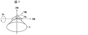
- FIG. 7 is a diagram illustrating a definition of a deformation amount of the suction pad used in one aspect of the present invention. First, the definition 1 of the deformation amount of the suction pad 112 will be described with reference to FIG. 7.
- the suction pad 112 has a substantially conical shape, and has a substantially conical shape with the lower surface (suction surface) Q open.
- the plane including the circular end portion of the suction pad 112 that comes into contact with the object is referred to as a suction surface.
- the X-axis and the Y-axis are taken in two directions parallel to the suction surface of the undeformed suction pad and orthogonal to each other, and the Z-axis is taken in the normal direction of the suction surface of the undeformed suction pad.
- the inclination of the suction surface in the suction pad 112 is represented by the rotation amount Mx around the X-axis and the rotation amount My around the Y-axis.
- the amount of deformation of the suction pad 112 is represented by the amount of pushing Z in the Mx, My, and Z-axis directions.
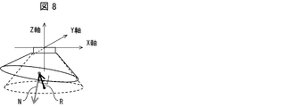
- FIG. 8 is a diagram illustrating a definition of a deformation amount of the suction pad used in one aspect of the present invention. Next, the definition 2 of the deformation amount of the suction pad 112 will be described with reference to FIG.
- R be the vector connecting the center of the suction surface of the undeformed suction pad and the center of the suction surface at the time of deformation.
- N be the unit normal vector of the suction surface at the time of deformation.
- the projection of the vector N on the X-axis is ex, the projection of the vector N on the Y-axis is ey, and the projection of the vector R on the Z-axis is ez.
- the X-axis component of the vector N is ex, the Y-axis component of the vector N is ey, and the Z-axis component of the vector R is ez.
- the amount of deformation of the suction pad 112 is represented by ⁇ ex, ey, ez ⁇ .
- FIG. 10 is a flowchart showing the operation of the controller 5 according to the embodiment of the present invention. First, with reference to FIG. 10, an operation example in which the suction pad 112 sucks and picks the work W will be described.
- Step S10 First, in step S10, the motion control unit 13 brings the suction pad 112 closer to the work W by lowering the suction pad 112 in the vertical direction.
- step S12 the operation control unit 13 determines whether or not at least a part of the suction pad 112 has come into contact with the work W.
- the suction pad 112 comes into contact with the work W, the suction pad 112 is tilted in the XY direction, and the tilt amount of the suction pad 112 represented by the absolute value of the vector (ex, ey) exceeds the threshold value ⁇ 1.
- the pushing amount ez in the Z-axis direction exceeds the threshold value ⁇ 2 the following equation holds.
- the motion control unit 13 determines that the suction pad 112 is in contact with the work W when the above equation is satisfied, and in other cases, the suction pad 112 is in contact with the work W. It is determined that the work W is not in contact with the work W.
- step S12 determines that the suction pad 112 has come into contact with the work W.
- step S12 If the operation control unit 13 does not determine that the suction pad 112 has come into contact with the work W (NO in step S12), the process returns to step S10 and the suction pad 112 continues to approach the work W.
- step S14 the motion control unit 13 determines whether or not the suction pad 112 and the work W have come into contact with each other as a whole.
- the suction pad 112 comes into contact with the work W as a whole, the inclination of the suction pad 112 is eliminated, so that the following equation is established.
- step S14 When the operation control unit 13 determines that the suction surface of the suction pad 112 and the work W are in contact with each other as a whole (YES in step S14), the control of the inclination of the suction pad 112 is completed, and the push-in amount control described later is completed. Move to.
- step S14 If the operation control unit 13 does not determine that the suction surface of the suction pad 112 and the work W have come into contact with each other as a whole (NO in step S14), the process proceeds to step S16.
- step S16 the contact point specifying portion 131 identifies the position of the contact point C between the suction pad 112 and the work W based on the deformation of the suction pad 112.
- FIG. 9A is a side view of the suction pad 112
- FIG. 9B is a top view of the suction pad 112.
- ⁇ the angle formed by projecting the inclination (vector N) of the suction pad 112 on the XY plane with the X axis
- ⁇ arctan (ey / ex)
- the contact point specifying unit 131 identifies the contact point C between the suction pad 112 and the work W from ⁇ . When the contact point is identified, the process proceeds to step S18.
- Step S18 the motion control unit 13 changes the inclination of the suction pad 112 while maintaining the contact between the suction pad 112 and the work W at the specified contact point C. That is, the inclination of the suction pad 112 is changed so as to reduce the angle formed by the suction surface of the suction pad 112 and the suction surface of the work W.
- the operation control unit 13 changes the inclination of the suction pad 112 to match the suction surface with the suction surface of the work W while maintaining the contact at the contact point by the following processing, and the manipulator unit 111 Request the operation command of.
- the suction pad 112 is removable from the robot arm.
- the operation control unit 13 combines the following two command values by combining the command speed (Pv) and the command angular velocity ( ⁇ ) for controlling the position and angle (posture) of the transfer hand, which is the base of the suction pad 112. Calculate as simple sum).
- the command angular velocity ( ⁇ ) is the rate of change of the angle of the transport hand. 1.
- Command speed Pv (more specifically, command speed vector) to maintain contact between the suction pad 112 and the work W at the contact point C.
- Pv (Pvr-Gv ⁇ ez) h
- Pvr is the target velocity of the suction pad 112
- Gv is a constant gain
- ez is the Z-axis component of the normal vector R representing the inclination of the suction pad 112
- h is the direction vector of the hand posture ( ⁇ ).
- " ⁇ " represents a product.
- Pe is the center of rotation
- P 0 is the offset of the suction pad installation position (the distance between the center of the suction surface of the suction pad 112 and the hand position of the carrier)
- Pr is the radius of the suction pad 112.
- FK is a kinematic function for finding ⁇ Pe, ⁇ e ⁇ from ⁇ P, ⁇ .
- the inverse kinematics function IK corresponding to FK exists and is written as follows.
- ⁇ P, ⁇ IK ( ⁇ Pe, ⁇ e ⁇ , ⁇ P 0 , Pr, ⁇ )
- the motion control unit 13 uses the above IK or the Jacobian derived from the IK. To determine ⁇ Pv, ⁇ . Let this set be the command speed and the command angular velocity.
- the operation control unit 13 changes the inclination of the suction pad 112 according to the obtained command speed. After that, the process proceeds to step S20.
- Step S20 the motion control unit 13 specifies whether or not the suction pad 112 and the work W have come into contact with each other as a whole. More specifically, the motion control unit 13 makes a determination by the same process as in step S14 described above. When the operation control unit 13 determines that the suction surface of the suction pad 112 and the work W have come into contact with each other as a whole (YES in step S20), the tilt control of the suction pad 112 is completed, and the control of the pushing amount is started.
- step S20 If the operation control unit 13 does not determine that the suction surface of the suction pad 112 and the work W have come into contact with each other as a whole (NO in step S20), the process returns to step S18 and continues to control the inclination of the suction pad 112.
- the operation control unit 13 identifies the position of the contact point C and the inclination of the suction pad 112, and maintains the contact at the contact point C.
- the inclination of the suction pad 112 is changed so that the suction pad 112 is brought into close contact with the surface to be sucked by the work W. Therefore, the posture of the suction pad 112 can be corrected with high accuracy, and the work W can be picked reliably.
- FIG. 11 is a flowchart showing the operation of the controller 5 in another embodiment of the present invention. Next, with reference to FIG. 11, an operation example in which the suction pad 112 pushes the work W before sucking or placing the object will be described.
- Step S110 First, in step S110, the operation control unit 13 brings the suction pad 112 closer to the work W by lowering the suction pad 112 in the vertical direction.
- Step S112 the operation control unit 13 determines whether or not the suction pad 112 has come into contact with the work W based on the amount of deformation of the suction pad 112.
- step S112 determines from the deformation amount of the suction pad 112 that the suction pad 112 has come into contact with the work W (YES in step S112)
- the process proceeds to step S114. If the operation control unit 13 does not determine that a part of the suction pad 112 has come into contact with the work W (NO in step S112), the process returns to step S110 and the suction pad 112 continues to approach the work W.
- step S114 the operation control unit 13 continues pushing the suction pad 112 into the work W.
- the operation control unit 13 may change the speed of the suction pad 112 according to the deformation of the suction pad 112.
- the motion control unit 13 may reduce the speed at which the suction pad 112 is brought closer to the work W when the deformation amount (pushing amount ez) of the suction pad 112 exceeds the first threshold value. That is, the operation control unit 13 may slow down the speed of the suction pad 112 in step S114 more than the speed of the suction pad 112 in step S110. Then, the process proceeds to step S116.
- step S116 the operation control unit 13 determines whether or not the suction pad 112 has been pushed into the work W. In this step, the operation control unit 13 determines that the pushing amount is sufficient when the following equation holds, assuming that the threshold value of the pushing amount ez of the suction pad 112 into the work W is ⁇ 2, and in other cases, the pushing amount is sufficient. It is not judged that the pushing amount is sufficient. ez> ⁇ 2
- the motion control unit 13 stops the movement of the suction pad 112. At this time, for example, the operation control unit 13 may stop the operation of bringing the suction pad 112 closer to the work W when the deformation amount of the suction pad 112 exceeds the second threshold value larger than the first threshold value.
- step S116 the operation control unit 13 turns on the vacuum pump 12 and starts sucking the object. If the deformation information acquisition unit 113 does not determine that the pressing of the suction pad 112 into the work W is completed (NO in step S116), the process returns to step S114 and the pressing is continued.
- the deformation information acquisition unit 113 determines whether to continue or stop the pushing while observing the pushing amount of the suction pad 112 into the work W based on the deformation amount of the suction pad 112. Therefore, since the amount ez of the suction pad 112 pushed into the work W can be kept within a certain range, the work W can be pushed appropriately when picking the work W or placing the work W. it can.
- Step S210 First, in step S210, the operation control unit 13 brings the suction pad 112 closer to the table (work W) by lowering the suction pad 112 in the vertical direction.
- step S212 the operation control unit 13 determines whether or not a part of the work W gripped by the suction pad 112 has come into contact with the table at the contact point C.
- the motion control unit 13 basically performs the same process as the process in step S12 in the above-described ⁇ operation example 1>.
- the amount of deformation ⁇ ex0, ey0, ez0 ⁇ of the suction pad 112 before the work W comes into contact with the table is not 0 due to the suction and the weight of the work W.
- the motion control unit 13 records the amount of deformation ⁇ ex0, ey0, ez0 ⁇ before the work W comes into contact with the table.
- the motion control unit 13 determines that the work W gripped by the suction pad 112 has come into contact with the table, and in other cases, the work W is in contact with the table. Judge that there is no.
- the process proceeds to step S214. If the motion control unit 13 does not determine that a part of the work W has contacted the table at the contact point C (NO in step S212), the process returns to step S210 and the work W continues to approach the table. ..
- step S214 the motion control unit 13 determines whether or not the lower surface of the work W and the base are in contact with each other as a whole.
- the motion control unit 13 determines that the lower surface of the work W is in total contact with the table when the above equation is satisfied, and in other cases, the lower surface of the work W is in total contact with the table. Judge that there is no.
- step S214 When the motion control unit 13 determines that the lower surface of the work W and the base are in contact with each other as a whole (YES in step S214), the motion control unit 13 completes the tilt control of the suction pad 112, and the push-in described above is performed. Move to quantity control. If the motion control unit 13 does not determine that the work W and the table have come into contact with each other as a whole (NO in step S14), the process proceeds to step S216.
- Step S216 the contact point specifying portion 131 identifies the position of the contact point C with the surface to be arranged on the table in the work W based on the deformation of the suction pad 112.
- the deformation information acquisition unit 113 performs basically the same processing as in step S16 of ⁇ Operation example 1>.
- the process proceeds to step S218.
- Step S2128 the motion control unit 13 changes the inclination of the suction pad 112 while maintaining the contact between the work W and the surface to be arranged on the table at the specified contact point (contact side). At this time, the inclination of the suction pad 112 is changed so as to reduce the angle formed by the surface of the suctioned work W that is not the surface to be suctioned and the surface to be arranged on the table.
- the motion control unit 13 basically performs the same process as step S18 in ⁇ Operation Example 1> described above, and changes the inclination of the work W while maintaining the contact at the contact point to change the suction pad 112. Find the command speed when aligning the suction surface of the table with the surface of the table.
- the operation control unit 13 uses the recorded offset ⁇ ex0, ey0, ez0 ⁇ to read and calculate the symbols as follows.
- Wh is the height of the work W
- Wl is the length of the work W
- FK is the same kinematic function as FK in step S18 in ⁇ operation example 1>.
- IK is also the same kinematic function as IK in step S18 in ⁇ Operation example 1>.
- the operation control unit 13 changes the inclination of the suction pad 112 according to the obtained command speed. Then, the process proceeds to step S220.
- Step S220 the motion control unit 13 determines whether or not the surface of the work W that is not the surface to be attracted and the surface to be arranged on the table are in contact with each other as a whole.
- the operation control unit 13 performs the same processing as in step S214 described above.
- step S220 When the operation control unit 13 determines that the surface of the work W that is not the surface to be attracted and the surface to be arranged on the table are in total contact (YES in step S220), the operation control unit 13 completes the tilt control of the suction pad 112. Then, stop the suction and release the work. If the motion control unit 13 does not determine that the surface of the work W that is not the surface to be attracted and the surface to be arranged on the table are in contact with each other as a whole (NO in step S220), the motion control unit 13 returns to step S218. , Continue tilt control.
- the operation control unit 13 specifies the position of the contact point C and the inclination of the suction pad 112 after the surface of the work W, which is not the surface to be attracted, and the surface to be arranged on the table come into contact with each other, and makes contact. While maintaining the contact at the point C, the inclination of the suction pad 112 is changed so that the surface of the work W, which is not the surface to be sucked, comes into contact with the surface to be arranged on the table as a whole. Therefore, the posture of the suction pad 112 can be corrected with high accuracy, and the work W can be placed at an accurate position. Further, it is possible to prevent an impact from being applied to the separated work W or the separated work from falling over.
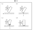
- FIGS. 13 and 14 (a) to (d) the suction pad 112 in a state where the work W is gripped under a situation where the direction of gravity is not clear is a target for arranging the side surface of the work W as a table.
- FIGS. 14A to 14D are side views showing the state of the work W and the table held by the suction pad 112. ..
- Step S310 First, in step S310, the motion control unit 13 brings the suction pad 112 in the state where the work W is gripped close to the surface to be arranged on the table ((a) in FIG. 14).
- Step S312 the motion control unit 13 determines whether or not a part of the side surface of the work W gripped by the suction pad 112 touches the table at the contact point C based on the amount of deformation of the suction pad 112. judge.
- the operation control unit 13 performs the same processing as in step S212 of ⁇ Operation Example 3> described above.
- the process proceeds to step S314 ((b) in FIG. 14).
- step S312 If the motion control unit 13 does not determine that a part of the side surface of the work W has touched the table (NO in step S312), the process returns to step S310, and the motion control unit 13 approaches the table of the work W. To continue.
- step S314 the contact point specifying portion 131 specifies the position of the contact point (contact side) with the surface to be arranged on the table in the work W based on the deformation of the suction pad 112.
- the motion control unit 13 performs the same process as step S216 of the above-described ⁇ operation example 3>.
- the motion control unit 13 rotates the work W around the contact point (contact side) toward the surface (placement target surface) of the table to be contacted ((c) in FIG. 14). That is, the motion control unit 13 performs the same process as step S218 of the above-described ⁇ operation example 3>.
- the process proceeds to step S316.
- step S316 the motion control unit 13 determines whether or not the side surface of the work W and the table have come into contact with each other as a whole. More specifically, the operation control unit 13 performs the same processing as in step S212 of ⁇ operation example 3>.
- the operation control unit 13 controls the inclination of the suction pad 112. Is completed, suction is stopped, and the work W is released. If the motion control unit 13 does not determine that the side surface of the work W and the table have come into contact with each other as a whole (NO in step S316), the process returns to step S314.
- the operation control unit 13 is the suction pad. After the side surface of the work W and the surface to be arranged on the table come into contact with each other at the contact point based on the amount of deformation of the 112, the position of the contact point and the inclination of the suction pad 112 are specified, and the work W and the table are placed at the contact point.
- the inclination of the suction pad 112 is changed so that the side surface of the work W to be contacted with the suction pad 112 touches the surface to be arranged on the table as a whole. Therefore, the posture of the suction pad 112 can be accurately corrected even in a situation where the direction of gravity is not clear, and the side surfaces of the work W can be appropriately faced to each other.
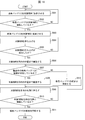
- FIG. 15 is a flowchart showing the control flow of the controller 5 in this case
- FIGS. 16A to 16C are side views showing the state of the work W and the table gripped by the suction pad 112. ..
- Step S410 First, in step S410, the motion control unit 13 brings the suction pad 112 in the state where the work W is gripped close to the arrangement target surface (vertical surface S1) of the table.
- Step S412 the motion control unit 13 makes a part of the side surface of the work W gripped by the suction pad 112 on the first surface S1 of the table at the contact side based on the deformation amount of the suction pad 112. Determine if they have touched.
- the operation control unit 13 performs the same processing as in step S212 of ⁇ Operation Example 3> described above.
- the motion control unit 13 determines that a part of the side surface of the work W has come into contact with the surface S1 of the table (YES in step S412), the process proceeds to step S414 ((a) in FIG. 14).
- step S412 If the motion control unit 13 does not determine that a part of the side surface of the work W has touched the table (NO in step S412), the process returns to step S410, and the motion control unit 13 approaches the table of the work W. To continue.
- step S414 the contact point specifying portion 131 specifies the position of the contact side of the work W with the surface S1 of the table based on the deformation of the suction pad 112.
- the operation control unit 13 performs the same processing as in step S216 of ⁇ operation example 3>.
- the motion control unit 13 rotates the work W around the contact side toward the surface (surface S3) of the table to be contacted.
- the surface S3 is a wall surface.
- step S416 the motion control unit 13 determines whether or not the side surface of the work W and the surface S3 of the table are in contact with each other as a whole.
- the operation control unit 13 performs the same processing as in step S214 of ⁇ operation example 3>.
- the process proceeds to step S418. If the motion control unit 13 does not determine that the side surface of the work W and the surface S3 of the table have come into contact with each other as a whole (NO in step S416), the process returns to step S414.
- Step S4108 the motion control unit 13 slides the work W toward the horizontal plane (surface S4) of the table on the surface S3 while maintaining the surface contact between the side surface of the work W and the surface S3 of the table. After that, the process proceeds to step S420.
- step S420 the motion control unit 13 determines whether or not the work W has surface contact with the surface S4 which is the second surface.
- the operation control unit 13 performs the same processing as in step S214 of ⁇ operation example 3>.
- the motion control unit 13 completes the face-to-face alignment process (YES in step S420).
- FIG. 14 (c) If the motion control unit 13 does not determine that the side surface of the work W and the surface S4 of the table are in surface contact (NO in step S420), the process returns to step S418.
- the operation control unit 13 can be used. Based on the amount of deformation of the suction pad 112, it is possible to determine that one surface of the work W and the first surface of the table are completely aligned, and then slide the work W toward the second surface. it can. Therefore, even in a situation where the direction of gravity is not clear, the posture of the suction pad 112 can be corrected accurately, and the work W can be accurately faced with the two surfaces of the table.
- FIG. 17 is a block diagram showing an example of a schematic configuration of a modified example of the suction device 1 according to the present embodiment.
- the controller 5 of the suction device 1 includes an image processing unit 119 and a deformation information acquisition unit 113, and the deformation information acquisition unit 113 includes a deformation amount change speed calculation unit 36 and a constant gain multiplication unit 37.
- the deformation amount change speed calculation unit 36 may be included in the image processing unit 119 instead of the deformation information acquisition unit 113.
- the suction device 1 provided with the controller 5 in the modified example includes a robot arm 11, a vacuum pump (not shown), and a controller 5.
- the robot arm 11 includes a suction pad 112, an image pickup device 121, and a manipulator unit 111.
- the image pickup apparatus 121 is fixed so as to be arranged on the side of the suction pad 112, and images the variable portion of the suction pad 112. By providing the image pickup device 121, the state before and after the deformation of the variable portion of the suction pad 112 can be acquired by an image or the like, and the deformation amount of the suction pad 112 can be calculated based on the acquired data.
- the controller 5 includes an image processing unit 119, a deformation information acquisition unit 113, and an operation control unit 13. Further, the image processing unit 119 includes an image acquisition unit 120, a feature point identification unit 123, and a deformation amount identification unit 124.
- the imaging device 121 images the variable portion of the suction pad 112.
- the image data may be monochrome image data or color image data.
- the image acquisition unit 120 acquires the image data captured by the image pickup device 121. Then, the image data is input to the feature point specifying unit 123.
- the feature point specifying unit 123 identifies the feature points of the variable unit included in the image data input from the image acquisition unit 120.
- the feature points in the image data corresponding to the plurality of parts of the variable portion 118 are specified from the pattern formed in the variable portion included in the input image data.
- the coordinate values of each feature point in the image coordinate system are output to the deformation amount specifying unit 124.
- the feature point identification unit 123 also specifies the coordinates (plurality of coordinates) of the non-deformable fixed portion of the suction pad 112 as reference coordinates. The displacement of the feature point can be obtained from the coordinates of the feature point with respect to the reference coordinates.
- the deformation amount specifying unit 124 specifies the deformation amount of a plurality of parts of the variable portion (and thus the deformation amount of the suction pad 112) from the feature points (coordinate values) output from the feature point identification unit 123 and the coordinates of the fixed portion. ..
- the deformation amount change speed calculation unit 36 calculates the change speed of the deformation amount by time-differentiating the deformation amount specified by the deformation amount specifying unit 124.
- the deformation amount change rate calculation unit 36 outputs the change rate of the deformation amount to the constant gain multiplication unit 37.
- the constant gain multiplication unit 37 calculates the deceleration value by multiplying the change speed of the deformation amount (for example, the angular velocity of the suction surface of the suction pad) calculated by the deformation amount change speed calculation unit 36 by a constant. Constant gain multiplication unit 37 outputs a deceleration value to the operation controller 13.
- the motion control unit 13 has a target moving speed of the suction pad 112 for transporting the object.
- the motion control unit 13 obtains the command speed by subtracting the deceleration value from the target moving speed.
- the operation control unit 13 controls the manipulator unit 111 so as to move the hand (suction pad 112) of the manipulator at a command speed.
- the vibration of the suction pad 112 (vibration of the object) can be suppressed by changing the hand speed of the robot arm so as to attenuate the change speed of the deformation amount of the suction pad 112.
- the motion control unit 13 may change the inclination of the suction pad 112 so as to reduce the change rate of the deformation amount based on the change rate of the deformation amount.
- the vibration of the suction pad 112 can be controlled by changing the inclination of the suction pad 112.
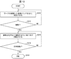
- FIG. 18 is a flowchart showing an example of the processing flow of the deformation example 3 of the deformation measuring device according to the present embodiment.
- the motion control unit 13 brings the suction pad 112 closer to the object W.
- the example of (a) in FIG. 19 shows S501.
- S502 it is determined whether or not the suction pad 112 is in contact with the object W. Whether or not the suction pad 112 is in contact with the object W can be determined by the amount of deformation of the variable portion of the suction pad 112. If the amount of deformation is equal to or greater than the threshold value, the motion control unit 13 determines that the suction pad 112 is in contact with the object W. When it is determined that the suction pad 112 is in contact with the object W (YES in S502), the suction pad 112 is sucked onto the object W (S503).
- the example of (b) in FIG. 19 shows S503. When it is determined that the suction pad 112 is not in contact with the object W (NO in S502), the processes of S501 to S502 are executed again.
- the motion control unit 13 causes the manipulator unit 111 to lift the object W.
- the example of (c) in FIG. 19 shows S504.
- the object W is transported to the target position (S506).
- the example of (d) in FIG. 19 shows S506.
- the processes of S504 to S505 are executed again.
- the operation control unit 13 determines whether or not vibration is generated in the suction pad 112 during transportation. If the rate of change of the deformation amount of the suction pad 12 is equal to or higher than another threshold value, the operation control unit 13 determines that the suction pad 112 during transportation is vibrating. When it is determined that vibration is not generated in the suction pad 112 during transportation (YES in S507), the object W is transported to the target position without changing the inclination of the object W (S508). When it is determined that vibration is generated in the suction pad 112 during transportation (YES in S507), the inclination of the suction pad 112 is controlled (S512). Then, the process of S507 is executed again.
- the motion control unit 13 causes the manipulator unit 111 to lower the object W to a target position.
- the example of (e) in FIG. 19 shows S209.
- S510 it is determined whether or not the object W is in contact with the target position. Whether or not the object W is in contact with the target position can be determined by the amount of deformation of the variable portion of the suction pad 112. If the amount of deformation is equal to or greater than another threshold value, the motion control unit 13 determines that the object W is in contact with the target position.
- the suction of the suction pad 112 is released (S511).
- the example of (f) in FIG. 19 shows the case of YES in S510.
- the processes of S509 to S510 are executed again.
- the control block of the mobile suction device 100 (particularly, each part of the controller 5 (negative pressure control unit 21, deformation information acquisition unit 113 and operation control unit 13), abnormality determination unit 115) is formed in an integrated circuit (IC chip) or the like. It may be realized by a logic circuit (hardware) or by software.
- the mobile suction device 100 includes a computer that executes a program instruction, which is software that realizes each function.
- the computer includes, for example, one or more processors and a computer-readable recording medium that stores the program. Then, in the computer, the processor reads the program from the recording medium and executes it, thereby achieving the object of the present invention.
- the processor for example, a CPU (Central Processing Unit) can be used.
- the recording medium in addition to a “non-temporary tangible medium” such as a ROM (Read Only Memory), a tape, a disk, a card, a semiconductor memory, a programmable logic circuit, or the like can be used.
- a RAM RandomAccessMemory
- the program may be supplied to the computer via an arbitrary transmission medium (communication network, broadcast wave, etc.) capable of transmitting the program.
- a transmission medium communication network, broadcast wave, etc.
- one aspect of the present invention can also be realized in the form of a data signal embedded in a carrier wave, in which the above program is embodied by electronic transmission.
- Suction device 100 Mobile suction device 2 Transport unit 3 Battery 5 Controller 11 Robot arm 12 Vacuum pump 13 Manipulator control unit (operation control unit) 14 Object information acquisition unit 15 Arrangement information acquisition unit 21 Negative pressure control unit 22 Automated guided vehicle 111 Manipulator unit 113 Deformation information acquisition unit 112 Suction unit (suction pad) 119 Image processing unit 120 Image acquisition unit 121 Imaging device 123 Feature point identification unit 124 Deformation amount identification unit 131 Contact point identification unit 114 Sensor 115 Abnormality determination unit 211 Analog signal output unit 221 Conveyance control unit
Landscapes
- Engineering & Computer Science (AREA)
- Mechanical Engineering (AREA)
- Robotics (AREA)
- Human Computer Interaction (AREA)
- Health & Medical Sciences (AREA)
- General Health & Medical Sciences (AREA)
- Orthopedic Medicine & Surgery (AREA)
- Manipulator (AREA)
Abstract
Description
図1は、本実施形態に係るコントローラ5の適用場面の一例を模式的に例示する。図2は、本実施形態に係るコントローラ5を搭載した移動吸着装置100における吸着パッド(吸着部)112および変形情報取得部113の一例を模式的に例示する。具体的には、図2の(a)は、吸着パッド112および変形情報取得部113の上面図の一例を模式的に例示する。また、図2の(b)は、吸着パッド112および変形情報取得部113の側面図の一例を模式的に例示する。
図4は、吸着パッド112で、台に並べられた複数の対象物(ワーク)のうちから一つのワークWをピッキングする場面を示す模式図である。まず、図4を参照して、本発明が対象物のピッキングに適用される場合の例について説明する。
図5は、吸着パッド112を台に載置されたワークWに押しつける場面を示す。このうち、図5の(a)は従来例における押込みの様子、図5の(b)は本発明の適用例における押込みの様子をそれぞれ示している。
図6では、ロボットアームに吸着された状態のワークWを、台にプレースする(置く)場面を示す。このうち、図6の(a)は従来例におけるプレースの様子、図6の(b)は本発明の適用例におけるプレースの様子をそれぞれ示している。
<移動吸着装置>
次に、図3の(a)および(b)を用いて、本実施形態に係るコントローラ5を備えた移動吸着装置100のハードウェア構成の一例について説明する。
吸着装置1は、ロボットアーム11と、真空ポンプ12と、動作制御部(マニピュレータ制御部)13とを備えている。
図2の例では、ロボットアーム11は、マニピュレータ部111と、吸着パッド112と、変形情報取得部113と動作制御部を備えている。
マニピュレータ部111は、動作制御部13の制御に基づき、ロボットアーム11における吸着パッド112と共に駆動する。マニピュレータ部111は、例えば1または複数の関節を有する。
吸着パッド112は、マニピュレータ部111の駆動によって作業位置に位置した場合、真空ポンプ12の駆動量に応じた負圧により対象物を吸着することによって、対象物の把持動作を行う。
変形情報取得部113は、吸着パッド112の変形の情報を取得する。例えば、変形情報取得部113は、歪みセンサー114から吸着パッド112の歪みを示すデータを取得する。変形情報取得部113は、歪みを示すデータから、吸着パッド112の変形量を特定する。変形量の具体例については後述する。
異常判定部115は、吸着パッド112が対象物を吸着(吸引)するのを止め、対象物を離してから、所定期間後の吸着パッド112の変形量が第2閾値以上であれば、対象物が吸着パッド112に張りついていると判定する。換言すれば、異常判定部115は、吸着パッド112と対象物との間の空間が真空状態でなくなってから(真空破壊をしてから)所定期間後の吸着パッド112の変形量が第2閾値以上であれば、対象物が吸着パッド112に張りついていると判定する。
真空ポンプ12は、駆動量に応じた負圧を発生させ、吸着パッド112に当該負圧を提供する。ここでは、移動吸着装置100における吸着装置1が真空ポンプ12を備えている例について説明している。ただし、本実施形態では、移動吸着装置100における吸着装置1は真空ポンプ12を備えておらず、例えば、吸着装置1および移動吸着装置100の外部に真空ポンプ12があってもよい。これによっても、負圧制御部21が真空ポンプ12の駆動量を制御することによって、上述の例と同様の効果を奏することができる。
動作制御部13は、CPU(Central Processing Unit)、RAM(Random Access Memory)またはROM(Read Only Memory)などを含み、情報処理に応じて制御を行う。また、マニピュレータ制御部13は、負圧制御部21から出力されたマニピュレータ制御信号に基づき、ロボットアーム11におけるマニピュレータ部111を制御する。これにより、マニピュレータ制御部13は、マニピュレータ部111を介して吸着パッド112を移動させる。具体的には、マニピュレータ制御部13は、ロボットアーム11における吸着パッド112が対象物を吸着可能な作業位置に位置するようにマニピュレータ部111を駆動させる。また、マニピュレータ制御部13は、吸着パッド112が作業位置に位置した後、対象物に対する吸着パッド112の角度が所定の角度となるように、マニピュレータ部111を動作させてもよい。これにより、吸着パッド112の位置をより好適な位置に微調整することができる。また、マニピュレータ制御部13は、吸着パッド112が対象物を吸着した後、例えば、ロボットアーム11における吸着パッド112が、マニピュレータ制御部13の上部に設置された所定の箱(不図示)の位置に位置するように、マニピュレータ部111を駆動させる。
搬送部(無人搬送車)2は、負圧制御部(制御信号出力部)21と、無人搬送車22とを備えている。
負圧制御部21は、CPU(Central Processing Unit)、RAM(Random Access Memory)またはROM(Read Only Memory)などを含み、情報処理に応じて制御を行う。負圧制御部21は、例えば、PLC(Programmable Logic Controller)またはマイコンなどによって構成される。負圧制御部21は、変形情報取得部113における1以上の歪みセンサー114から受信する出力信号、および、無人搬送車22における搬送制御部221から受信する搬送状態信号に基づいて、負圧を発生させる真空ポンプ12を制御する。
図3の例では、無人搬送車22は、搬送制御部221を備えている。搬送制御部221は、無人搬送車22の搬送を制御することによって、移動吸着装置100の移動(搬送)を制御する。例えば、搬送制御部221は、ロボットアーム11によって対象物を把持することができる作業位置まで移動吸着装置100を移動させる。また、搬送制御部221は、移動吸着装置100が、既に作業位置に位置する場合は、移動吸着装置100を移動させない。また、無人搬送車22は、無人搬送車22の搬送状態を示す信号である搬送状態信号を負圧制御部21に送信する。
バッテリー3は、移動吸着装置100の各部、すなわち、吸着装置1および搬送部2に電力を供給することによって移動吸着装置100の各部を制御する。
コントローラ5は、上述したように、吸着パッド112の変形の情報を取得する変形情報取得部113と、吸着パッド112の変形に応じて、吸着パッド112の動きを制御する動作制御部13とを備える。つまり、動作制御部13は、吸着パッド112の変形に応じて、吸着パッド112の動き(移動方向、速度、および/または傾き)を変更する。
動作制御部13は、さらに接触点特定部131を備えていてもよい。接触点特定部131は、前記吸着パッド112の変形(変形量、変形速度、または変形加速度)に基づいて、前記吸着パッド112における前記対象物との接触点を特定する。また接触点特定部131は、吸着パッド112が対象物を吸着している状態において、吸着パッド112の変形(変形量、変形速度、または変形加速度)に基づいて、前記対象物における配置対象面との接触点を特定する。上述の構成によれば、対象物と移動吸着装置100との位置姿勢関係に計測誤差が存在していても、接触点特定部131によって特定された接触点を支点に吸着面側へ吸着部(吸着パッド)112の姿勢を傾ける動きを、マニピュレータ制御部13がマニピュレータ部111に行わせることによって、計測誤差を吸収することができる。その結果、吸着部112による対象物のピッキングミスをより好適に防止することができる。詳細は後述する。
以下に、本発明に係るコントローラ5の様々な動作例について説明する。
次に、図7および8を用いて、吸着パッド112の変形量の定義を説明する。
図10は、本発明の一実施形態におけるコントローラ5の動作を示すフローチャートである。まず、図10を参照して、吸着パッド112がワークWを吸着し、ピッキングする場合の動作例を説明する。
まず、ステップS10では、動作制御部13が、吸着パッド112を鉛直方向に降下させることにより、吸着パッド112をワークWに接近させる。
次に、ステップS12では、動作制御部13が、吸着パッド112の少なくとも一部がワークWに接触したか否かを判定する。ここで、吸着パッド112がワークWに接触した場合には、吸着パッド112にXY方向の傾きが生じ、ベクトル(ex、ey)の絶対値で表す吸着パッド112の傾き量が閾値ε1を超える、または、Z軸方向の押込量ezが閾値ε2を超えるため、以下の式が成立する。
|(ex、ey)|>ε1、または、ez>ε2
そのため、より具体的には、動作制御部13は、本ステップにおいて、上記式が成立する場合には、吸着パッド112がワークWに接触したと判定し、それ以外の場合は、吸着パッド112がワークWに接触していないと判定する。
次に、ステップS14では、動作制御部13が、吸着パッド112とワークWが全体で接触したかどうかを判定する。ここで、吸着パッド112がワークWに全体で接触した場合には、吸着パッド112の傾きが解消されるため、以下の式が成立する。
|(ex、ey)|<ε1
そのため、動作制御部13は、本ステップにおいて、上記式が成立する場合には、吸着パッド112の吸着面がワークWに全体で接触したと判定し、それ以外の場合は、吸着パッド112の吸着面がワークWに全体で接触していないと判定する。
ステップS16では、接触点特定部131が、吸着パッド112の変形に基づいて、吸着パッド112とワークWの接触点Cの位置を特定する。
θ=arctan(ey/ex)
接触点特定部131は、θから吸着パッド112とワークWの接触点Cを特定する。
接触点が特定されたら、ステップS18へ進む。
ステップS18では、動作制御部13は、前記特定された接触点Cにおける吸着パッド112とワークWとの接触を維持したまま、吸着パッド112の傾きを変更する。つまり、吸着パッド112が有する吸着面とワークWの被吸着面とのなす角を減少させるよう、吸着パッド112の傾きを変更する。ここで、動作制御部13は、以下の処理により、接触点での接触を維持しながら、吸着パッド112の傾きを変更して吸着面をワークWの被吸着面に合わせる場合の、マニピュレータ部111の動作指令を求める。
1.接触点Cにおける吸着パッド112とワークWの接触を維持させるため指令速度Pv(より具体的には指令速度ベクトル)
Pv=(Pvr-Gv・ez)h
ここで、Pvrは吸着パッド112の目標速度、Gvは定数ゲイン、ezは吸着パッド112の傾きを表す法線ベクトルRのZ軸成分、hは手先姿勢(φ)の方向ベクトルである。また、「・」は積を表す。
2.接触点Cを支点に吸着パッド112を回転させる指令速度(Pv)および指令角速度(φω)
接触点を拡張された手先として、接触点の位置姿勢を{Pe、φe}とおく。ステップS18においてexおよびeyは微小であるので、φe=φとする。{Pe、φe}は図9におけるパッド設置位置オフセット(Po)、パッド半径(Pr)、ステップS16で求めたθと元々の手先位置姿勢{P、φ}を用いて、以下の通り表される。
{Pe, φe}=FK({P、φ}、{P0、Pr、θ})
ここで、Peは回転中心、P0は吸着パッド設置位置のオフセット(吸着パッド112の吸着面の中心と搬送機手先位置の距離)、Prは吸着パッド112の半径である。また、FKは{P、Φ}から{Pe、Φe}を求める運動学関数である。FKに対応する逆運動学関数IKは存在し、以下の通り書くものとする。
{P、 φ}=IK({Pe、 φe}、{P0、Pr、θ})
Peを回転中心として、Peと吸着パッド112の中心軸を通る平面での回転を与える指令を{Pev, φev}とすると、動作制御部13は、上記IK、もしくはIKから誘導されるヤコビアンを用いて{Pv, φω}を決定する。この組を指令速度および指令角速度とする。
ステップS20では、動作制御部13が、吸着パッド112とワークWが全体で接触したか否かを特定する。より具体的には、動作制御部13が、上述したステップS14と同様の処理により判定を行う。動作制御部13が、吸着パッド112の吸着面とワークWが全体で接触したと判定したら(ステップS20でYES)、吸着パッド112の傾き制御を完了し、押込量の制御に移行する。動作制御部13が、吸着パッド112の吸着面とワークWが全体で接触したと判定しなかった(ステップS20でNO)場合には、ステップS18に戻り、吸着パッド112の傾きの制御を続ける。
図11は、本発明の他の実施形態におけるコントローラ5の動作を示すフローチャートである。次に、図11を参照して、対象物の吸着前またはプレース前に、吸着パッド112がワークWを押込む場合の動作例を説明する。
まず、ステップS110では、動作制御部13が、吸着パッド112を鉛直方向に降下させることにより、吸着パッド112をワークWに接近させる。
次に、ステップS112では、動作制御部13が、吸着パッド112の変形量から吸着パッド112がワークWに接触したか否かを判定する。
次に、ステップS114では、動作制御部13が吸着パッド112のワークWへの押し込みを続行する。この場合、動作制御部13は、吸着パッド112の変形に応じて、前記吸着パッド112の速度を変更してもよい。例えば、動作制御部13は、吸着パッド112の変形量(押込量ez)が第1閾値を超えると、吸着パッド112をワークWに近づける速度を減速してもよい。つまり、動作制御部13は、ステップS110での吸着パッド112の速度よりもステップS114での吸着パッド112の速度を減速させてもよい。その後、ステップS116に進む。
ステップS116では、動作制御部13が、吸着パッド112のワークWへの押込が完了したか否かを判定する。動作制御部13は、本ステップにおいて、吸着パッド112のワークWへの押込量ezの閾値をε2とすると、下記式が成り立つとき、押込量が充分であると判定し、それ以外の場合には押込量が充分であると判定しない。
ez>ε2
そして、動作制御部13が、吸着パッド112のワークWへの押込が完了したと判定した場合(ステップS116でYES)には、動作制御部13が吸着パッド112の動きを停止する。このとき、例えば、動作制御部13は、吸着パッド112の変形量が、前記第1閾値よりも大きい第2閾値を超えると、吸着パッド112をワークWに近づける動作を停止してもよい。
次に、図12を参照して、ワークWを把持した状態の吸着パッド112がワークWを台にプレースする場合の動作例を説明する。
まず、ステップS210では、動作制御部13が、吸着パッド112を鉛直方向に降下させることにより、吸着パッド112を(ワークWを)台に接近させる。
次に、ステップS212では、動作制御部13が、吸着パッド112に把持されたワークWの一部が接触点Cで台に接触したか否かを判定する。ここで、動作制御部13は、基本的に上述した<動作例1>におけるステップS12での処理と同じ処理を行う。ただし、吸引およびワークWの重量によって、ワークWが台に接触する前の吸着パッド112の変形量{ex0、ey0、ez0}は0ではない。動作制御部13は、ワークWが台に接触する前の変形量{ex0、ey0、ez0}を記録しておく。そして、以下の式が成立する場合には、動作制御部13は、吸着パッド112に把持されたワークWが台に接触したと判定し、それ以外の場合は、ワークWは台に接触していないと判定する。
|(ex-ex0、ey-ey0)|>ε4、または、|ez-ez0|>ε5
動作制御部13が、ワークWの一部(非吸着面)が台に接触したと判定した場合(ステップS212でYES)には、ステップS214に進む。動作制御部13が、ワークWの一部が台に接触点Cで接触したと判定しなかった場合(ステップS212でNO)には、ステップS210に戻り、ワークWの台への接近を続行する。
次に、ステップS214では、動作制御部13が、ワークWの下面と台が全体で接触したかどうかを判定する。ここで、ワークWの下面が台に全体で接触した場合には、吸着パッド112およびワークWの傾きが解消されるため、以下の式が成立する。
|(ex-ex0、ey-ey0)|<ε4
したがって、動作制御部13は、上記式が成立する場合には、ワークWの下面が台に全体で接触したと判定し、それ以外の場合は、ワークWの下面が台に全体では接触していないと判定する。
ステップS216では、接触点特定部131が、吸着パッド112の変形に基づいて、ワークWにおける台の配置対象面との接触点Cの位置を特定する。ここで、変形情報取得部113は、<動作例1>のステップS16と基本的に同様の処理を行う。但し、記録したオフセット{ex0、ey0、ez0}を用いて、以下の通り計算する。
θ=arctan((ey-ey0)/(ex-ex0))
上記処理により、ワークWにおける台の配置対象面との接触点Cが特定されたら、ステップS218へ進む。
ステップS218では、動作制御部13は、前記特定された接触点(接触辺)におけるワークWと台の配置対象面との接触を維持したまま、吸着パッド112の傾きを変更する。この時、吸着されているワークWの被吸着面ではない表面と、台の配置対象面とのなす角を減少させるよう、吸着パッド112の傾きを変更する。
・ez→ez-ez0
・{Pe、φe}:吸着パッド112とワークWの接触点→ワークWと台の接触点
・{FK({P、φ}、{P0、Pr、θ})→{FK({P、φ}、{P0+Wh/2、Pr+Wl/2、θ})
ここで、WhはワークWの高さ、WlはワークWの長さであり、FKは<動作例1>でのステップS18のFKと同じ運動学関数である。
{P, φ}=IK({Pe, φe}、{P0、Pr、θ})→
{P, φ}=IK({Pe, φe}、{P0+Wh/2、Pr+Wl/2、θ})
上記でIKも<動作例1>でのステップS18のIKと同じ運動学関数である。
次に、ステップ220では、動作制御部13が、ワークWの被吸着面ではない表面と台の配置対象面が全体で接触したか否かを判定する。ここで、動作制御部13が、上述のステップS214と同様の処理を行う。
次に、図13および図14の(a)から(d)を参照して、重力方向が明らかでない状況下で、ワークWを把持した状態の吸着パッド112がワークWの側面を台の配置対象面に対して面合わせする場合の動作例を説明する。図13は、この場合のコントローラ5の制御の流れを示すフローチャートであり、図14(a)から(d)は、吸着パッド112に把持されたワークWおよび台の様子を示した側面図である。
まず、ステップS310では、動作制御部13が、ワークWが把持された状態の吸着パッド112を台の配置対象面に接近させる(図14の(a))。
次に、ステップS312では、動作制御部13が、吸着パッド112の変形量に基づいて、吸着パッド112に把持されたワークWの側面の一部が接触点Cで台に接触したか否かを判定する。ここで、動作制御部13は、上述した<動作例3>のステップS212と同様の処理を行う。動作制御部13が、ワークWの側面の一部が台に接触したと判定した場合(ステップS312でYES)には、ステップS314に進む(図14の(b))。
次に、ステップS314では、接触点特定部131が、吸着パッド112の変形に基づいて、ワークWにおける台の配置対象面との接触点(接触辺)の位置を特定する。ここで、動作制御部13は、上述した<動作例3>のステップS216と同様の処理を行う。そして、動作制御部13は、接触点(接触辺)を中心にワークWを台の接触させたい面(配置対象面)に向けて回転させる(図14の(c))。つまり、動作制御部13が、上述した<動作例3>のステップS218と同様の処理を行う。その後、ステップS316へ進む。
次に、ステップS316では、動作制御部13が、ワークWの側面と台が全体で接触したかどうかを判定する。より具体的には、動作制御部13が、<動作例3>のステップS212と同様の処理を行う。変形情報取得部113が、ワークWの側面と台が全体で接触したと判定した場合には(ステップS316でYES、図14の(d))、動作制御部13は、吸着パッド112の傾き制御を完了し、吸着を停止しワークWを解放する。動作制御部13が、ワークWの側面と台が全体で接触したと判定しなかった場合(ステップS316でNO)には、ステップS314に戻る。
次に、図15および図16の(a)から(c)を参照して、重力方向が明らかでない状況下で、ワークWを把持した状態の吸着パッド112がワークWの2側面を台の2面に対して面合わせする場合の動作例を説明する。図15は、この場合のコントローラ5の制御の流れを示すフローチャートであり、図16(a)から(c)は、吸着パッド112に把持されたワークWおよび台の様子を示した側面図である。
まず、ステップS410では、動作制御部13が、ワークWが把持された状態の吸着パッド112を台の配置対象面(垂直な面S1)に接近させる。
次に、ステップS412では、動作制御部13が、吸着パッド112の変形量に基づいて、吸着パッド112に把持されたワークWの側面の一部が接触辺で台の一つ目の面S1に接触したか否かを判定する。ここで、動作制御部13は、上述した<動作例3>のステップS212と同様の処理を行う。動作制御部13が、ワークWの側面の一部が台の面S1に接触したと判定した場合(ステップS412でYES)には、ステップS414に進む(図14の(a))。
次に、ステップS414では、接触点特定部131が、吸着パッド112の変形に基づいて、ワークWにおける台の面S1との接触辺の位置を特定する。ここで、動作制御部13は、<動作例3>のステップS216と同様の処理を行う。そして、動作制御部13が、接触辺を中心にワークWを台の接触させたい面(面S3)に向けて回転させる。ここでは面S3は壁面である。その後、ステップS416へ進む。
次に、ステップS416では、動作制御部13が、ワークWの側面と台の面S3が全体で接触したかどうかを判定する。ここで、動作制御部13は、<動作例3>のステップS214と同様の処理を行う。動作制御部13が、ワークWの側面と台の面S3が全体で接触したと判定した場合には(ステップS416でYES、図14の(b))、ステップS418へ進む。動作制御部13が、ワークWの側面と台の面S3が全体で接触したと判定しなかった場合(ステップS416でNO)には、ステップS414に戻る。
次に、ステップS418では、動作制御部13が、ワークWの側面と台の面S3の面接触を維持しながら、ワークWを台の水平面(面S4)に向けて面S3上を滑らせる。その後、ステップS420へ進む。
次に、ステップS420では、動作制御部13が、ワークWが二つ目の面である面S4に面接触したか否かを判定する。ここで、動作制御部13が、<動作例3>のステップS214と同様の処理を行う。動作制御部13が、ワークWの側面と台の2つ目の面S4が全体で接触したと判定した場合には(ステップS420でYES)、動作制御部13は面合わせの処理を完了する(図14の(c))。動作制御部13が、ワークWの側面と台の面S4が面接触したと判定しなかった場合(ステップS420でNO)には、ステップS418に戻る。
図17は、本実施形態に係る吸着装置1の変形例の概略構成の一例を示すブロック図である。図17の例では、吸着装置1のコントローラ5が画像処理部119および変形情報取得部113を備え、変形情報取得部113が変形量変化速度計算部36と定数ゲイン乗算部37とを備える。なお。変形量変化速度計算部36は、変形情報取得部113ではなく画像処理部119に含まれていてもよい。
移動吸着装置100の制御ブロック(特にコントローラ5の各部(負圧制御部21、変形情報取得部113および動作制御部13)、異常判定部115)は、集積回路(ICチップ)等に形成された論理回路(ハードウェア)によって実現してもよいし、ソフトウェアによって実現してもよい。
100 移動吸着装置
2 搬送部
3 バッテリー
5 コントローラ
11 ロボットアーム
12 真空ポンプ
13 マニピュレータ制御部(動作制御部)
14 対象物情報取得部
15 配置情報取得部
21 負圧制御部
22 無人搬送車
111 マニピュレータ部
113 変形情報取得部
112 吸着部(吸着パッド)
119 画像処理部
120 画像取得部
121 撮像装置
123 特徴点特定部
124 変形量特定部
131 接触点特定部
114 センサー
115 異常判定部
211 アナログ信号出力部
221 搬送制御部
Claims (12)
- 負圧により対象物を吸着し、該負圧によって変形する吸着部の変形の情報を取得する変形情報取得部と、
前記吸着部の変形に応じて、前記吸着部の動きを制御する動作制御部とを備える、コントローラ。 - 前記動作制御部は、前記吸着部の変形に応じて、前記吸着部の傾きを変更する、請求項1に記載のコントローラ。
- 前記動作制御部は、前記吸着部が有する吸着面と前記対象物の被吸着面とのなす角を減少させるよう、前記吸着部の傾きを変更する、請求項2に記載のコントローラ。
- 前記動作制御部は、前記吸着部の変形に基づいて、前記吸着部における前記対象物との接触点を特定する接触点特定部を備え、
前記動作制御部は、前記接触点における前記吸着部と前記対象物との接触を維持したまま、前記吸着部の傾きを変更する、請求項2または3に記載のコントローラ。 - 前記動作制御部は、前記吸着部が有する吸着面の中心軸と、前記接触点とを含む平面内において、前記吸着部を回転させる、請求項4に記載のコントローラ。
- 前記吸着部が前記対象物を吸着している状態において、前記動作制御部は、吸着されている前記対象物の被吸着面ではない表面と、配置対象面とのなす角を減少させるよう、前記吸着部の傾きを変更する、請求項2に記載のコントローラ。
- 前記動作制御部は、前記吸着部が前記対象物を吸着している状態において、前記吸着部の変形に基づいて、前記対象物における配置対象面との接触点を特定する接触点特定部を備え、
前記動作制御部は、前記接触点における前記対象物と前記配置対象面との接触を維持したまま、前記吸着部の傾きを変更する、請求項2または6に記載のコントローラ。 - 前記動作制御部は、前記吸着部の変形に応じて、前記吸着部の速度を変更する、請求項1から7のいずれか一項に記載のコントローラ。
- 前記動作制御部は、前記吸着部の変形量が第1閾値を超えると、前記吸着部を前記対象物に近づける速度を減速する、請求項8に記載のコントローラ。
- 前記動作制御部は、前記吸着部の変形量が第2閾値を超えると、前記吸着部を前記対象物に近づける動作を停止する、請求項8または9に記載のコントローラ。
- 前記変形情報取得部は、前記吸着部の変形量および/または変形速度を取得し、
前記動作制御部は、前記吸着部の前記変形量および/または前記変形速度に応じて、前記吸着部の動きを制御する、請求項1から10のいずれか一項に記載のコントローラ。 - 負圧により対象物を吸着し、該負圧によって変形する吸着部を備える吸着装置の制御方法であって、
前記吸着部の変形の情報を取得する変形情報取得ステップと、
前記吸着部の変形に応じて、前記吸着部の動きを制御する動作制御ステップとを含む、吸着装置の制御方法。
Priority Applications (5)
| Application Number | Priority Date | Filing Date | Title |
|---|---|---|---|
| PCT/JP2019/018993 WO2020230250A1 (ja) | 2019-05-13 | 2019-05-13 | コントローラ |
| EP19928418.3A EP3970926A4 (en) | 2019-05-13 | 2019-05-13 | Controller |
| JP2021519087A JP7303454B2 (ja) | 2019-05-13 | 2019-05-13 | コントローラ |
| CN201980095478.8A CN113727817B (zh) | 2019-05-13 | 2019-05-13 | 控制器 |
| US17/604,799 US12269694B2 (en) | 2019-05-13 | 2019-05-13 | Controller |
Applications Claiming Priority (1)
| Application Number | Priority Date | Filing Date | Title |
|---|---|---|---|
| PCT/JP2019/018993 WO2020230250A1 (ja) | 2019-05-13 | 2019-05-13 | コントローラ |
Publications (1)
| Publication Number | Publication Date |
|---|---|
| WO2020230250A1 true WO2020230250A1 (ja) | 2020-11-19 |
Family
ID=73289853
Family Applications (1)
| Application Number | Title | Priority Date | Filing Date |
|---|---|---|---|
| PCT/JP2019/018993 Ceased WO2020230250A1 (ja) | 2019-05-13 | 2019-05-13 | コントローラ |
Country Status (5)
| Country | Link |
|---|---|
| US (1) | US12269694B2 (ja) |
| EP (1) | EP3970926A4 (ja) |
| JP (1) | JP7303454B2 (ja) |
| CN (1) | CN113727817B (ja) |
| WO (1) | WO2020230250A1 (ja) |
Cited By (2)
| Publication number | Priority date | Publication date | Assignee | Title |
|---|---|---|---|---|
| JP2024035688A (ja) * | 2022-09-02 | 2024-03-14 | 東京エレクトロン株式会社 | 基板処理装置、基板形状特定方法、搬送装置、及びエンドエフェクタ |
| JP2025504598A (ja) * | 2022-03-18 | 2025-02-12 | 三菱電機株式会社 | ロボットによる組み立て中に部品を再配向するためのロバスト枢動のためのシステムおよび方法 |
Families Citing this family (1)
| Publication number | Priority date | Publication date | Assignee | Title |
|---|---|---|---|---|
| US12441002B2 (en) * | 2021-12-10 | 2025-10-14 | Boston Dynamics, Inc. | Robotic gripper with seal detection |
Citations (7)
| Publication number | Priority date | Publication date | Assignee | Title |
|---|---|---|---|---|
| JPH0672974U (ja) * | 1993-03-31 | 1994-10-11 | 株式会社芝浦製作所 | 搬送装置 |
| JPH11333776A (ja) * | 1998-05-26 | 1999-12-07 | Matsushita Electric Works Ltd | 組立ハンド |
| JP2004306169A (ja) * | 2003-04-03 | 2004-11-04 | Nissan Motor Co Ltd | 吸着装置 |
| JP2005262325A (ja) * | 2004-03-16 | 2005-09-29 | Central Glass Co Ltd | 吸着ハンドおよび該吸着ハンドの姿勢追従方法 |
| WO2016142981A1 (ja) * | 2015-03-06 | 2016-09-15 | 株式会社日立製作所 | 作業ロボット及びグリッパ |
| JP2018089719A (ja) | 2016-11-30 | 2018-06-14 | 株式会社東芝 | ロボットハンド |
| JP2019005866A (ja) * | 2017-06-26 | 2019-01-17 | 株式会社妙徳 | 吸着装置 |
Family Cites Families (16)
| Publication number | Priority date | Publication date | Assignee | Title |
|---|---|---|---|---|
| JPH06335877A (ja) | 1993-05-27 | 1994-12-06 | Agency Of Ind Science & Technol | 真空吸着装置 |
| US7645111B2 (en) | 2002-11-05 | 2010-01-12 | Central Glass Company, Limited | System for putting glass plates to target positions |
| CN2603501Y (zh) | 2003-03-04 | 2004-02-11 | 上海旭电子玻璃有限公司 | 显象管玻壳锥体浮动夹具 |
| JP4698674B2 (ja) | 2005-08-05 | 2011-06-08 | 平田機工株式会社 | ワーク吸着ヘッド |
| DE102005045681B4 (de) * | 2005-09-24 | 2007-07-26 | Eckelt Glas Gmbh | Verfahren zum Steuern von Unterdruck-Hebezeugen und Lastsicherungsvorrichtung für Unterdruck-Hebezeuge sowie deren Verwendung |
| JP2007253249A (ja) | 2006-03-20 | 2007-10-04 | Honda Motor Co Ltd | 吸着装置及びこの吸着装置を用いた吸着方法 |
| JP4926690B2 (ja) * | 2006-12-20 | 2012-05-09 | 株式会社アイ・アンド・ティー | ワーク吸着装置 |
| US7971916B2 (en) * | 2008-05-22 | 2011-07-05 | GM Global Technology Operations LLC | Reconfigurable robotic end-effectors for material handling |
| JP2010131743A (ja) * | 2008-10-30 | 2010-06-17 | Canon Inc | 力覚センサを内蔵した把持装置 |
| EP3341163B1 (en) * | 2015-08-26 | 2023-04-19 | Berkshire Grey Operating Company, Inc. | Systems and methods for providing contact detection in an articulated arm |
| US11370128B2 (en) | 2015-09-01 | 2022-06-28 | Berkshire Grey Operating Company, Inc. | Systems and methods for providing dynamic robotic control systems |
| ES2845683T3 (es) * | 2015-09-01 | 2021-07-27 | Berkshire Grey Inc | Sistemas y métodos para proporcionar sistemas de control robótico dinámico |
| DE102015218195A1 (de) * | 2015-09-22 | 2017-03-23 | Robert Bosch Gmbh | Vorrichtung zur Aktivierung zumindest eines Greifers |
| JP2017154888A (ja) * | 2016-03-04 | 2017-09-07 | 株式会社東芝 | 物品保持システム、物品保持装置及び物品保持方法 |
| CN108058185B (zh) | 2017-12-20 | 2021-03-26 | Tcl华星光电技术有限公司 | 吸盘式机械爪及机械臂 |
| CN108161645B (zh) | 2018-01-05 | 2019-10-29 | 大连理工大学 | 一种低刚度高精度平面镜的工件旋转法磨削装置及方法 |
-
2019
- 2019-05-13 JP JP2021519087A patent/JP7303454B2/ja active Active
- 2019-05-13 EP EP19928418.3A patent/EP3970926A4/en active Pending
- 2019-05-13 CN CN201980095478.8A patent/CN113727817B/zh active Active
- 2019-05-13 US US17/604,799 patent/US12269694B2/en active Active
- 2019-05-13 WO PCT/JP2019/018993 patent/WO2020230250A1/ja not_active Ceased
Patent Citations (7)
| Publication number | Priority date | Publication date | Assignee | Title |
|---|---|---|---|---|
| JPH0672974U (ja) * | 1993-03-31 | 1994-10-11 | 株式会社芝浦製作所 | 搬送装置 |
| JPH11333776A (ja) * | 1998-05-26 | 1999-12-07 | Matsushita Electric Works Ltd | 組立ハンド |
| JP2004306169A (ja) * | 2003-04-03 | 2004-11-04 | Nissan Motor Co Ltd | 吸着装置 |
| JP2005262325A (ja) * | 2004-03-16 | 2005-09-29 | Central Glass Co Ltd | 吸着ハンドおよび該吸着ハンドの姿勢追従方法 |
| WO2016142981A1 (ja) * | 2015-03-06 | 2016-09-15 | 株式会社日立製作所 | 作業ロボット及びグリッパ |
| JP2018089719A (ja) | 2016-11-30 | 2018-06-14 | 株式会社東芝 | ロボットハンド |
| JP2019005866A (ja) * | 2017-06-26 | 2019-01-17 | 株式会社妙徳 | 吸着装置 |
Non-Patent Citations (1)
| Title |
|---|
| See also references of EP3970926A4 |
Cited By (3)
| Publication number | Priority date | Publication date | Assignee | Title |
|---|---|---|---|---|
| JP2025504598A (ja) * | 2022-03-18 | 2025-02-12 | 三菱電機株式会社 | ロボットによる組み立て中に部品を再配向するためのロバスト枢動のためのシステムおよび方法 |
| JP7785200B2 (ja) | 2022-03-18 | 2025-12-12 | 三菱電機株式会社 | ロボットによる組み立て中に部品を再配向するためのロバスト枢動のためのシステムおよび方法 |
| JP2024035688A (ja) * | 2022-09-02 | 2024-03-14 | 東京エレクトロン株式会社 | 基板処理装置、基板形状特定方法、搬送装置、及びエンドエフェクタ |
Also Published As
| Publication number | Publication date |
|---|---|
| US20220212884A1 (en) | 2022-07-07 |
| JP7303454B2 (ja) | 2023-07-05 |
| CN113727817A (zh) | 2021-11-30 |
| EP3970926A4 (en) | 2022-07-06 |
| US12269694B2 (en) | 2025-04-08 |
| CN113727817B (zh) | 2024-05-28 |
| EP3970926A1 (en) | 2022-03-23 |
| JPWO2020230250A1 (ja) | 2020-11-19 |
Similar Documents
| Publication | Publication Date | Title |
|---|---|---|
| JP7507284B2 (ja) | ロボットハンド、ロボット及びロボットシステム | |
| US8295975B2 (en) | Object picking device | |
| CN110465960B (zh) | 具有物件丢失管理机制的机器人系统 | |
| EP3173194B1 (en) | Manipulator system, image capturing system, transfer method of object, and carrier medium | |
| US20080118338A1 (en) | Transfer robot | |
| CN102189551A (zh) | 机器人系统以及搬运方法 | |
| JP7188574B2 (ja) | 吸着パッド、および変形計測装置 | |
| CN103193085B (zh) | 搬运系统 | |
| CN206717896U (zh) | 用于抓取零件的机器人系统及其夹具 | |
| JP2016055389A (ja) | 物品搬送システム | |
| CN105514010B (zh) | 一种硅片安全运输方法 | |
| WO2008051544A1 (en) | Improved calibration of a substrate handling robot | |
| JP7303454B2 (ja) | コントローラ | |
| JP2023082176A (ja) | 開閉式物体用のロボットグリッパアセンブリ及び物体をピッキングするための方法 | |
| US20180272537A1 (en) | Robot control device, robot, and robot system | |
| WO2019240273A1 (ja) | 情報処理装置、情報処理装置を備える荷降しシステム、及びコンピュータ可読記憶媒体 | |
| JP7275830B2 (ja) | 吸着装置および移動吸着装置 | |
| JP7192682B2 (ja) | 検査システム | |
| KR20230119518A (ko) | 충전 기능을 포함하는 기판 이송 시스템 | |
| JP7264241B2 (ja) | センサー体、及び吸着装置 | |
| JP2007069316A (ja) | 物品搬送ロボット | |
| TW202025341A (zh) | 基板搬送機器人及目標體之邊緣位置教示方法 | |
| CN118295220A (zh) | 接触式曝光机的硅片定位系统及其硅片定位方法 |
Legal Events
| Date | Code | Title | Description |
|---|---|---|---|
| 121 | Ep: the epo has been informed by wipo that ep was designated in this application |
Ref document number: 19928418 Country of ref document: EP Kind code of ref document: A1 |
|
| ENP | Entry into the national phase |
Ref document number: 2021519087 Country of ref document: JP Kind code of ref document: A |
|
| NENP | Non-entry into the national phase |
Ref country code: DE |
|
| ENP | Entry into the national phase |
Ref document number: 2019928418 Country of ref document: EP Effective date: 20211213 |
|
| WWG | Wipo information: grant in national office |
Ref document number: 17604799 Country of ref document: US |