WO2020230482A1 - 充放電装置、充放電制御方法、及びコンピュータプログラム - Google Patents
充放電装置、充放電制御方法、及びコンピュータプログラム Download PDFInfo
- Publication number
- WO2020230482A1 WO2020230482A1 PCT/JP2020/015758 JP2020015758W WO2020230482A1 WO 2020230482 A1 WO2020230482 A1 WO 2020230482A1 JP 2020015758 W JP2020015758 W JP 2020015758W WO 2020230482 A1 WO2020230482 A1 WO 2020230482A1
- Authority
- WO
- WIPO (PCT)
- Prior art keywords
- vehicle
- charging
- charge
- relay
- discharging
- Prior art date
- Legal status (The legal status is an assumption and is not a legal conclusion. Google has not performed a legal analysis and makes no representation as to the accuracy of the status listed.)
- Ceased
Links
Images








Classifications
-
- B—PERFORMING OPERATIONS; TRANSPORTING
- B60—VEHICLES IN GENERAL
- B60L—PROPULSION OF ELECTRICALLY-PROPELLED VEHICLES; SUPPLYING ELECTRIC POWER FOR AUXILIARY EQUIPMENT OF ELECTRICALLY-PROPELLED VEHICLES; ELECTRODYNAMIC BRAKE SYSTEMS FOR VEHICLES IN GENERAL; MAGNETIC SUSPENSION OR LEVITATION FOR VEHICLES; MONITORING OPERATING VARIABLES OF ELECTRICALLY-PROPELLED VEHICLES; ELECTRIC SAFETY DEVICES FOR ELECTRICALLY-PROPELLED VEHICLES
- B60L53/00—Methods of charging batteries, specially adapted for electric vehicles; Charging stations or on-board charging equipment therefor; Exchange of energy storage elements in electric vehicles
- B60L53/60—Monitoring or controlling charging stations
- B60L53/62—Monitoring or controlling charging stations in response to charging parameters, e.g. current, voltage or electrical charge
-
- B—PERFORMING OPERATIONS; TRANSPORTING
- B60—VEHICLES IN GENERAL
- B60L—PROPULSION OF ELECTRICALLY-PROPELLED VEHICLES; SUPPLYING ELECTRIC POWER FOR AUXILIARY EQUIPMENT OF ELECTRICALLY-PROPELLED VEHICLES; ELECTRODYNAMIC BRAKE SYSTEMS FOR VEHICLES IN GENERAL; MAGNETIC SUSPENSION OR LEVITATION FOR VEHICLES; MONITORING OPERATING VARIABLES OF ELECTRICALLY-PROPELLED VEHICLES; ELECTRIC SAFETY DEVICES FOR ELECTRICALLY-PROPELLED VEHICLES
- B60L53/00—Methods of charging batteries, specially adapted for electric vehicles; Charging stations or on-board charging equipment therefor; Exchange of energy storage elements in electric vehicles
- B60L53/10—Methods of charging batteries, specially adapted for electric vehicles; Charging stations or on-board charging equipment therefor; Exchange of energy storage elements in electric vehicles characterised by the energy transfer between the charging station and the vehicle
- B60L53/14—Conductive energy transfer
-
- B—PERFORMING OPERATIONS; TRANSPORTING
- B60—VEHICLES IN GENERAL
- B60L—PROPULSION OF ELECTRICALLY-PROPELLED VEHICLES; SUPPLYING ELECTRIC POWER FOR AUXILIARY EQUIPMENT OF ELECTRICALLY-PROPELLED VEHICLES; ELECTRODYNAMIC BRAKE SYSTEMS FOR VEHICLES IN GENERAL; MAGNETIC SUSPENSION OR LEVITATION FOR VEHICLES; MONITORING OPERATING VARIABLES OF ELECTRICALLY-PROPELLED VEHICLES; ELECTRIC SAFETY DEVICES FOR ELECTRICALLY-PROPELLED VEHICLES
- B60L53/00—Methods of charging batteries, specially adapted for electric vehicles; Charging stations or on-board charging equipment therefor; Exchange of energy storage elements in electric vehicles
- B60L53/10—Methods of charging batteries, specially adapted for electric vehicles; Charging stations or on-board charging equipment therefor; Exchange of energy storage elements in electric vehicles characterised by the energy transfer between the charging station and the vehicle
- B60L53/14—Conductive energy transfer
- B60L53/18—Cables specially adapted for charging electric vehicles
-
- B—PERFORMING OPERATIONS; TRANSPORTING
- B60—VEHICLES IN GENERAL
- B60L—PROPULSION OF ELECTRICALLY-PROPELLED VEHICLES; SUPPLYING ELECTRIC POWER FOR AUXILIARY EQUIPMENT OF ELECTRICALLY-PROPELLED VEHICLES; ELECTRODYNAMIC BRAKE SYSTEMS FOR VEHICLES IN GENERAL; MAGNETIC SUSPENSION OR LEVITATION FOR VEHICLES; MONITORING OPERATING VARIABLES OF ELECTRICALLY-PROPELLED VEHICLES; ELECTRIC SAFETY DEVICES FOR ELECTRICALLY-PROPELLED VEHICLES
- B60L53/00—Methods of charging batteries, specially adapted for electric vehicles; Charging stations or on-board charging equipment therefor; Exchange of energy storage elements in electric vehicles
- B60L53/30—Constructional details of charging stations
-
- B—PERFORMING OPERATIONS; TRANSPORTING
- B60—VEHICLES IN GENERAL
- B60L—PROPULSION OF ELECTRICALLY-PROPELLED VEHICLES; SUPPLYING ELECTRIC POWER FOR AUXILIARY EQUIPMENT OF ELECTRICALLY-PROPELLED VEHICLES; ELECTRODYNAMIC BRAKE SYSTEMS FOR VEHICLES IN GENERAL; MAGNETIC SUSPENSION OR LEVITATION FOR VEHICLES; MONITORING OPERATING VARIABLES OF ELECTRICALLY-PROPELLED VEHICLES; ELECTRIC SAFETY DEVICES FOR ELECTRICALLY-PROPELLED VEHICLES
- B60L53/00—Methods of charging batteries, specially adapted for electric vehicles; Charging stations or on-board charging equipment therefor; Exchange of energy storage elements in electric vehicles
- B60L53/60—Monitoring or controlling charging stations
- B60L53/66—Data transfer between charging stations and vehicles
-
- B—PERFORMING OPERATIONS; TRANSPORTING
- B60—VEHICLES IN GENERAL
- B60L—PROPULSION OF ELECTRICALLY-PROPELLED VEHICLES; SUPPLYING ELECTRIC POWER FOR AUXILIARY EQUIPMENT OF ELECTRICALLY-PROPELLED VEHICLES; ELECTRODYNAMIC BRAKE SYSTEMS FOR VEHICLES IN GENERAL; MAGNETIC SUSPENSION OR LEVITATION FOR VEHICLES; MONITORING OPERATING VARIABLES OF ELECTRICALLY-PROPELLED VEHICLES; ELECTRIC SAFETY DEVICES FOR ELECTRICALLY-PROPELLED VEHICLES
- B60L53/00—Methods of charging batteries, specially adapted for electric vehicles; Charging stations or on-board charging equipment therefor; Exchange of energy storage elements in electric vehicles
- B60L53/60—Monitoring or controlling charging stations
- B60L53/68—Off-site monitoring or control, e.g. remote control
-
- B—PERFORMING OPERATIONS; TRANSPORTING
- B60—VEHICLES IN GENERAL
- B60L—PROPULSION OF ELECTRICALLY-PROPELLED VEHICLES; SUPPLYING ELECTRIC POWER FOR AUXILIARY EQUIPMENT OF ELECTRICALLY-PROPELLED VEHICLES; ELECTRODYNAMIC BRAKE SYSTEMS FOR VEHICLES IN GENERAL; MAGNETIC SUSPENSION OR LEVITATION FOR VEHICLES; MONITORING OPERATING VARIABLES OF ELECTRICALLY-PROPELLED VEHICLES; ELECTRIC SAFETY DEVICES FOR ELECTRICALLY-PROPELLED VEHICLES
- B60L55/00—Arrangements for supplying energy stored within a vehicle to a power network, i.e. vehicle-to-grid [V2G] arrangements
-
- B—PERFORMING OPERATIONS; TRANSPORTING
- B60—VEHICLES IN GENERAL
- B60L—PROPULSION OF ELECTRICALLY-PROPELLED VEHICLES; SUPPLYING ELECTRIC POWER FOR AUXILIARY EQUIPMENT OF ELECTRICALLY-PROPELLED VEHICLES; ELECTRODYNAMIC BRAKE SYSTEMS FOR VEHICLES IN GENERAL; MAGNETIC SUSPENSION OR LEVITATION FOR VEHICLES; MONITORING OPERATING VARIABLES OF ELECTRICALLY-PROPELLED VEHICLES; ELECTRIC SAFETY DEVICES FOR ELECTRICALLY-PROPELLED VEHICLES
- B60L58/00—Methods or circuit arrangements for monitoring or controlling batteries or fuel cells, specially adapted for electric vehicles
- B60L58/10—Methods or circuit arrangements for monitoring or controlling batteries or fuel cells, specially adapted for electric vehicles for monitoring or controlling batteries
- B60L58/12—Methods or circuit arrangements for monitoring or controlling batteries or fuel cells, specially adapted for electric vehicles for monitoring or controlling batteries responding to state of charge [SoC]
- B60L58/13—Maintaining the SoC within a determined range
-
- H—ELECTRICITY
- H01—ELECTRIC ELEMENTS
- H01M—PROCESSES OR MEANS, e.g. BATTERIES, FOR THE DIRECT CONVERSION OF CHEMICAL ENERGY INTO ELECTRICAL ENERGY
- H01M10/00—Secondary cells; Manufacture thereof
- H01M10/42—Methods or arrangements for servicing or maintenance of secondary cells or secondary half-cells
- H01M10/48—Accumulators combined with arrangements for measuring, testing or indicating the condition of cells, e.g. the level or density of the electrolyte
-
- H—ELECTRICITY
- H02—GENERATION; CONVERSION OR DISTRIBUTION OF ELECTRIC POWER
- H02J—ELECTRIC POWER NETWORKS; CIRCUIT ARRANGEMENTS OR SYSTEMS FOR SUPPLYING OR DISTRIBUTING ELECTRIC POWER; SYSTEMS FOR STORING ELECTRIC ENERGY
- H02J3/00—Circuit arrangements for AC mains or AC distribution networks
- H02J3/28—Arrangements for balancing of the load in networks by storage of energy
- H02J3/32—Arrangements for balancing of the load in networks by storage of energy using batteries or super capacitors with converting means
- H02J3/322—Arrangements for balancing of the load in networks by storage of energy using batteries or super capacitors with converting means the battery being on-board an electric or hybrid vehicle, e.g. vehicle to grid arrangements [V2G], power aggregation, use of the battery for network load balancing, coordinated or cooperative battery charging
-
- H—ELECTRICITY
- H02—GENERATION; CONVERSION OR DISTRIBUTION OF ELECTRIC POWER
- H02J—ELECTRIC POWER NETWORKS; CIRCUIT ARRANGEMENTS OR SYSTEMS FOR SUPPLYING OR DISTRIBUTING ELECTRIC POWER; SYSTEMS FOR STORING ELECTRIC ENERGY
- H02J7/00—Circuit arrangements for charging or discharging batteries or for supplying loads from batteries
- H02J7/80—Circuit arrangements for charging or discharging batteries or for supplying loads from batteries including monitoring or indicating arrangements
- H02J7/82—Control of state of charge [SOC]
-
- H—ELECTRICITY
- H02—GENERATION; CONVERSION OR DISTRIBUTION OF ELECTRIC POWER
- H02J—ELECTRIC POWER NETWORKS; CIRCUIT ARRANGEMENTS OR SYSTEMS FOR SUPPLYING OR DISTRIBUTING ELECTRIC POWER; SYSTEMS FOR STORING ELECTRIC ENERGY
- H02J7/00—Circuit arrangements for charging or discharging batteries or for supplying loads from batteries
- H02J7/80—Circuit arrangements for charging or discharging batteries or for supplying loads from batteries including monitoring or indicating arrangements
- H02J7/82—Control of state of charge [SOC]
- H02J7/825—Detection of fully charged condition
-
- H—ELECTRICITY
- H02—GENERATION; CONVERSION OR DISTRIBUTION OF ELECTRIC POWER
- H02J—ELECTRIC POWER NETWORKS; CIRCUIT ARRANGEMENTS OR SYSTEMS FOR SUPPLYING OR DISTRIBUTING ELECTRIC POWER; SYSTEMS FOR STORING ELECTRIC ENERGY
- H02J7/00—Circuit arrangements for charging or discharging batteries or for supplying loads from batteries
- H02J7/855—Circuit arrangements for charging or discharging batteries or for supplying loads from batteries with circuits adapted for supplying loads from the battery
-
- H—ELECTRICITY
- H02—GENERATION; CONVERSION OR DISTRIBUTION OF ELECTRIC POWER
- H02J—ELECTRIC POWER NETWORKS; CIRCUIT ARRANGEMENTS OR SYSTEMS FOR SUPPLYING OR DISTRIBUTING ELECTRIC POWER; SYSTEMS FOR STORING ELECTRIC ENERGY
- H02J2105/00—Networks for supplying or distributing electric power characterised by their spatial reach or by the load
- H02J2105/30—Networks for supplying or distributing electric power characterised by their spatial reach or by the load the load networks being external to vehicles, i.e. exchanging power with vehicles
- H02J2105/33—Networks for supplying or distributing electric power characterised by their spatial reach or by the load the load networks being external to vehicles, i.e. exchanging power with vehicles exchanging power with road vehicles
- H02J2105/37—Networks for supplying or distributing electric power characterised by their spatial reach or by the load the load networks being external to vehicles, i.e. exchanging power with vehicles exchanging power with road vehicles exchanging power with electric vehicles [EV] or with hybrid electric vehicles [HEV]
-
- H—ELECTRICITY
- H02—GENERATION; CONVERSION OR DISTRIBUTION OF ELECTRIC POWER
- H02J—ELECTRIC POWER NETWORKS; CIRCUIT ARRANGEMENTS OR SYSTEMS FOR SUPPLYING OR DISTRIBUTING ELECTRIC POWER; SYSTEMS FOR STORING ELECTRIC ENERGY
- H02J7/00—Circuit arrangements for charging or discharging batteries or for supplying loads from batteries
- H02J7/40—Circuit arrangements for charging or discharging batteries or for supplying loads from batteries characterised by the exchange of charge or discharge related data
-
- Y—GENERAL TAGGING OF NEW TECHNOLOGICAL DEVELOPMENTS; GENERAL TAGGING OF CROSS-SECTIONAL TECHNOLOGIES SPANNING OVER SEVERAL SECTIONS OF THE IPC; TECHNICAL SUBJECTS COVERED BY FORMER USPC CROSS-REFERENCE ART COLLECTIONS [XRACs] AND DIGESTS
- Y02—TECHNOLOGIES OR APPLICATIONS FOR MITIGATION OR ADAPTATION AGAINST CLIMATE CHANGE
- Y02E—REDUCTION OF GREENHOUSE GAS [GHG] EMISSIONS, RELATED TO ENERGY GENERATION, TRANSMISSION OR DISTRIBUTION
- Y02E60/00—Enabling technologies; Technologies with a potential or indirect contribution to GHG emissions mitigation
-
- Y—GENERAL TAGGING OF NEW TECHNOLOGICAL DEVELOPMENTS; GENERAL TAGGING OF CROSS-SECTIONAL TECHNOLOGIES SPANNING OVER SEVERAL SECTIONS OF THE IPC; TECHNICAL SUBJECTS COVERED BY FORMER USPC CROSS-REFERENCE ART COLLECTIONS [XRACs] AND DIGESTS
- Y02—TECHNOLOGIES OR APPLICATIONS FOR MITIGATION OR ADAPTATION AGAINST CLIMATE CHANGE
- Y02T—CLIMATE CHANGE MITIGATION TECHNOLOGIES RELATED TO TRANSPORTATION
- Y02T10/00—Road transport of goods or passengers
- Y02T10/80—Technologies aiming to reduce greenhouse gasses emissions common to all road transportation technologies
- Y02T10/92—Energy efficient charging or discharging systems for batteries, ultracapacitors, supercapacitors or double-layer capacitors specially adapted for vehicles
-
- Y—GENERAL TAGGING OF NEW TECHNOLOGICAL DEVELOPMENTS; GENERAL TAGGING OF CROSS-SECTIONAL TECHNOLOGIES SPANNING OVER SEVERAL SECTIONS OF THE IPC; TECHNICAL SUBJECTS COVERED BY FORMER USPC CROSS-REFERENCE ART COLLECTIONS [XRACs] AND DIGESTS
- Y04—INFORMATION OR COMMUNICATION TECHNOLOGIES HAVING AN IMPACT ON OTHER TECHNOLOGY AREAS
- Y04S—SYSTEMS INTEGRATING TECHNOLOGIES RELATED TO POWER NETWORK OPERATION, COMMUNICATION OR INFORMATION TECHNOLOGIES FOR IMPROVING THE ELECTRICAL POWER GENERATION, TRANSMISSION, DISTRIBUTION, MANAGEMENT OR USAGE, i.e. SMART GRIDS
- Y04S30/00—Systems supporting specific end-user applications in the sector of transportation
- Y04S30/10—Systems supporting the interoperability of electric or hybrid vehicles
- Y04S30/12—Remote or cooperative charging
Definitions
- the present invention relates to a charge / discharge device connected to a storage battery provided in a vehicle, a charge / discharge control method, and a computer program.
- the battery capacity of the storage battery installed in an electric vehicle is, for example, 5 to 100 kWh, which is a relatively large capacity.
- V2H Vehicle to Home
- V2B Vehicle to Building
- V2G Vehicle to Grid
- V2G Vehicle to Grid
- Patent Document 1 describes a charging / discharging device for realizing V2H, and charges / discharges the vehicle and the charging / discharging device on the charging / discharging device side without turning on the relay on the charging / discharging device side interposed in the power line connected to the storage battery of the vehicle.
- a device that controls charging / discharging by grasping the connection with the device has been proposed.
- Patent Document 2 describes a hunting phenomenon in which the voltage from a commercial power source is repeatedly stepped down and recovered in order to protect an in-vehicle charge / discharge circuit including an ADCC converter that adjusts the power to a storage battery provided in an electric vehicle. It is disclosed to stop charging when it occurs.
- Patent No. 5642226 Japanese Unexamined Patent Publication No. 2013-090459
- the detection of the connection of the power line between the vehicle and the charging / discharging device, the establishment of the communication connection between the vehicle and the charging / discharging device, and the start and stop of charging / discharging are performed. It is safely performed according to a predetermined sequence according to any of the charge / discharge methods. Charging / discharging control needs to take steps according to this predetermined sequence, and it is difficult to respond to a control instruction from EMS, which requires a high-speed response. In order to switch between charge / discharge operation and stop, it is necessary to switch ON / OFF of the DC relay on the vehicle side, the DC relay on the charge / discharge device side, and the disconnection relay. When the switching of the operation mode is repeated in accordance with the fine control, the relays are turned on and off frequently and deteriorated, which may cause early damage.
- An object of the present invention is to provide a charge / discharge device, a charge / discharge control method, and a computer program that exhibit high responsiveness while suppressing deterioration while following a predetermined sequence according to a charge / discharge method.
- the charging / discharging device of the embodiment of the present disclosure is a charging / discharging device that has a connector with an in-vehicle power line connected to a storage battery provided in a vehicle and controls charging / discharging in the storage battery, and is via the in-vehicle power line.
- a communication unit that communicates and connects to an in-vehicle control device that switches ON and OFF of a relay on the vehicle side, a communication control unit that transmits and receives a message from the communication unit based on a predetermined sequence between the in-vehicle control device, and a communication control unit. After switching the relay on the vehicle side to ON based on the predetermined sequence, the connection that maintains the connection standby state in which the relay on the vehicle side remains ON while the storage battery is not being charged or discharged. It is provided with a standby state maintenance unit.
- the charge / discharge control method of the embodiment of the present disclosure is a method in which a charge / discharge device having a connector with an in-vehicle power line connected to a storage battery provided in a vehicle controls charge / discharge in the storage battery.
- the discharge device communicates with an in-vehicle control device that switches ON / OFF of a relay on the vehicle side interposed in the in-vehicle power line, sends and receives a message to and from the in-vehicle control device based on a predetermined sequence, and receives the predetermined After switching the relay on the vehicle side to ON based on the sequence of, the connection standby state in which the relay on the vehicle side remains ON is maintained while the storage battery is not being charged or discharged.
- the computer program of the embodiment of the present disclosure has an in-vehicle power line connected to a storage battery provided in the vehicle, and is an in-vehicle control device that switches ON / OFF of a relay on the vehicle side interposed in the in-vehicle power line.
- a message is transmitted and received by the communication unit to and from the computer mounted on the charging / discharging device provided with the communication unit to be communicated with the vehicle based on the predetermined sequence, and the vehicle side is based on the predetermined sequence.
- the relay is switched to ON, the process of maintaining the connection standby state in which the relay on the vehicle side remains ON is executed while the storage battery is not being charged or discharged.
- the relay on the vehicle side is maintained so as not to be switched off by the control in the charge / discharge control device on the vehicle side.
- the procedure according to a predetermined sequence must be re-executed before charging / discharging is started, and when it takes time, this time is reduced and the relay on the vehicle side is turned on. By keeping it at, a fast response to charge / discharge control is achieved.
- the charging / discharging device includes a charging / discharging circuit including a relay for switching ON / OFF of power transfer between the storage battery and a commercial power source or a load, and the connection standby state is the vehicle.
- the relay on the side is ON, and the relay of the charge / discharge circuit is OFF.
- the relay of the charging / discharging circuit is interposed between the disconnection relay for switching ON / OFF of power transfer to / from the commercial power source and the connector.
- the connection standby state including the device-side relay, the disconnection relay is OFF and the device-side relay is ON.
- the connection standby state in which the relay on the vehicle side is left ON at least one of the plurality of relays provided inside the charging / discharging device is turned OFF.
- the device-side relay interposed between the charge / discharge circuit and the connector remains ON in the same manner as the vehicle-side relay.
- the disconnection relay provided inside the charging / discharging device may also be kept ON, and in this case, the response can be performed at a higher speed.
- connection standby state maintaining unit turns off the relay on the charging / discharging circuit side, and the in-vehicle control device is determined to be charging or discharging.
- a message indicating the charge / discharge current value of is transmitted by the communication control unit.
- the vehicle-mounted control device can keep the relay on the vehicle side ON while charging / discharging with the minimum current value.
- the connection standby state maintaining unit determines whether or not the charging rate of the storage battery is equal to or higher than a predetermined first charging rate determined to be fully charged. When it is determined that the charge rate is 1 or more, a message indicating the discharge current value determined to be discharging is transmitted to the in-vehicle control device.
- the relay on the vehicle side can be kept ON on the assumption that the minimum discharge is being carried out by the in-vehicle control device.
- the connection standby state maintaining unit determines whether or not the charging rate of the storage battery is equal to or lower than a predetermined second charging rate at which the charging rate of the storage battery is determined to be the lower limit. If it is determined that the charge rate is equal to or higher than the second charge rate, the power from the commercial power source is supplied by turning on the relay of the charge / discharge circuit until the charge rate of the storage battery reaches a predetermined third charge rate. Charges the storage battery and transmits a message indicating the charging current value to the in-vehicle control device.
- the relay on the vehicle side can be kept ON assuming that the minimum charge is being carried out.
- the connection standby state maintaining unit determines whether or not a predetermined time has elapsed from the start of maintaining the connection standby state, and the charge rate of the storage battery is the lower limit. At least one of the conditions of whether or not the charge rate is equal to or less than the predetermined second charge rate, or whether or not the charge rate of the storage battery has decreased by a predetermined rate or more since the maintenance of the connection standby state is started. When one is satisfied, the relay on the vehicle side is turned off and the communication connection by the communication unit is disconnected.
- the relay is used when there is a possibility that the remaining power of the storage battery will continue to be consumed even in the connection standby state in which the relay on the vehicle side is left ON for a long time. Turn it off and disconnect the communication connection. As a result, it operates properly as a charging / discharging device without maintaining an excessive connection.
- the charging / discharging device includes a charging / discharging circuit including a relay for switching ON / OFF of power transfer between the storage battery and a commercial power source or a load, and the connection standby state maintaining unit includes a charging / discharging circuit. While both the relay on the vehicle side and the relay of the charge / discharge circuit are turned on, charging or discharging is performed with the electric power set in the lower limit.
- the relay provided inside the charging / discharging device may be kept ON, and in this case, the response can be performed at a higher speed.
- the connection standby state maintenance unit performs charging / discharging with the minimum output.
- the "lower limit” and “minimum” are not limited to zero, and may be, for example, an output of 50 to 100 W.
- the charge / discharge device is acquired from the in-vehicle control device by the upper control communication unit that exchanges data with the upper control device that instructs charging / discharging in the storage battery of the vehicle, and the communication unit.
- the unit Based on the information about the storage battery and the instruction from the higher-level control device received by the higher-level control communication unit, the unit includes a determination unit for determining whether or not to transition to the protection state for protecting the relay.
- the charging / discharging method of the embodiment of the present disclosure is a method of having a connector with an in-vehicle power line connected to a storage battery provided in a vehicle and controlling charging / discharging in the storage battery, and is interposed in the in-vehicle power line.
- the in-vehicle control device that switches and controls ON / OFF of the relay on the vehicle side is connected by communication, data is exchanged with a higher-level control device that instructs charging / discharging in the storage battery of the vehicle, and data is acquired from the in-vehicle control device by communication. Based on the information about the storage battery and the instruction received from the host control device, it is determined whether or not to transition to the protection state for protecting the relay.
- the computer program of the embodiment of the present disclosure has an in-vehicle power line connected to a storage battery provided in the vehicle, and is an in-vehicle control device that switches ON / OFF of a relay on the vehicle side interposed in the in-vehicle power line.
- Information about the storage battery is transmitted from the in-vehicle control device to a computer mounted on a charging / discharging device including a first communication unit for communicating with the first communication unit and a second communication unit for exchanging data with a higher-level control device.
- the charge / discharge instruction in the storage battery is acquired from the upper control device via the second communication unit, and based on the information about the storage battery and the instruction from the upper control device. ,
- the process of determining whether or not to transition to the protection state that protects the relay is executed.
- the relay of the vehicle When it is expected that the relay of the vehicle will be repeatedly turned on and off, the state will be changed to the protected state. In the protected state, do not turn the vehicle relay on and off as much as possible. In the protected state, it is preferable that the relay provided in the charging / discharging device is also controlled so as not to be turned ON and OFF as much as possible.
- the charging / discharging device of one embodiment of the present disclosure in the protected state, there is no response to the charging instruction or the discharging instruction from the higher-level control device, or a negative response to the instruction is returned.
- a non-response a non-response, a NACK (Negative Acknowledge) response, or the like is returned to the EMS.
- a negative response indicates that the instruction has been accepted but does not respond to the instruction.
- a higher-level control device such as EMS may infer that the control instruction being transmitted is inappropriate for the connected vehicle because the charging / discharging device becomes unresponsive or returns a negative response. There is.
- the charging / discharging device transmits a transition notification to the protected state by the second communication unit.
- the transition notification to the protected state is transmitted to the EMS.
- the transition notification to the protected state it may be possible to infer that the control instruction being transmitted is inappropriate for the connected vehicle.
- the determination unit determines that the state transitions to the protected state when the same instruction is repeatedly received from the higher-level control device within a predetermined period.
- the charging / discharging device of the present disclosure when the same instruction is repeatedly received from the EMS or the internal controller, it is expected that the instruction is not appropriate and the process corresponding to the instruction is not executed on the vehicle side, and the process is executed. Since it is assumed that the same instruction will be repeated after that because it is not performed, it is judged that the judgment is made.
- the determination unit determines that the protection state is entered when the charging instruction and the discharging instruction are switched a plurality of times or more in a predetermined period from the higher-level control device.
- the charging / discharging device of the present disclosure if different instructions are repeated a plurality of times or more in a predetermined period from the EMS or the internal controller, it is expected that the instructions are not appropriate for the vehicle and the instructions are repeated. As a result, the relay is repeatedly switched on and off, so that the determination unit determines that the transition to the protected state is made.
- the determination unit determines that the vehicle-mounted control device switches the relay on the vehicle side to OFF and repeatedly receives the same instruction to transition to the protected state. To do.
- the determination unit determines that the transition to the protected state is made.
- the determination unit receives a charging instruction from the higher-level control device in a state where the charging rate of the storage battery is equal to or higher than a predetermined first ratio determined to be fully charged. In this case, or when a discharge instruction is received from the upper control device in a state where the charge rate of the storage battery is equal to or less than a predetermined second ratio determined to be the lower limit, it is determined that the state transitions to the protection state.
- the determination unit determines that the transition to the protected state is made.
- the determination unit acquires information on the vehicle type of the vehicle by the first communication unit, and transitions to the protected state based on the transition condition stored for each vehicle type. Judge whether or not.
- the charging / discharging device of the present disclosure it is determined whether or not to transition to the protected state under the transition conditions according to the vehicle type. It is possible to appropriately mediate between the charge control content on the vehicle side and the instructions from various EMSs.
- the determination unit determines that the protection state is restored after a predetermined waiting time has elapsed after the transition to the protection state.
- the protected state after transitioning to the protected state, the protected state may be restored after a predetermined standby time has elapsed.
- the determination unit determines that the charge rate of the storage battery acquired by the first communication unit is less than the predetermined first ratio, or the charge rate of the storage battery. Is determined to recover from the protection state when the predetermined second ratio is exceeded.
- the relay is switched ON / OFF again by returning from the protected state. Can be prevented from being repeated.
- the reset instruction is an instruction by an operation on a user-operable interface or an instruction from a higher-level control device that maintains a communication connection.
- the connected state of the in-vehicle power line is maintained, and it is not necessary to redo the sequence, so that high responsiveness to the charge / discharge instruction can be exhibited.
- FIG. 1 It is a schematic diagram of the charge / discharge apparatus and EMS of Embodiment 1. It is a block diagram which shows the connection structure of the charge / discharge device and the vehicle of Embodiment 1.
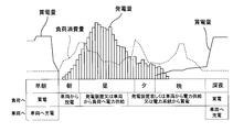
- FIG. It is a figure which shows the outline of the charge / discharge controlled by EMS.
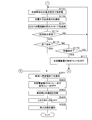
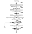
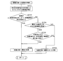
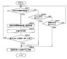
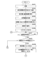
- It is a flowchart which shows an example of the processing procedure by the control part of a charge / discharge device. It is a flowchart which shows an example of the processing procedure by the control part of a charge / discharge device. It is a flowchart which shows an example of the control procedure for maintaining a "connection standby state”. It is a flowchart which shows an example of the control procedure which changes a state between a "connection standby state” and a "disconnection standby state”.
- FIG. 1 is a schematic view of the charging / discharging device 1 and the EMS 200 of the first embodiment.
- the load 21, the power generation device 23, and the charging / discharging device 1 arranged in the home are connected by a power line PL via a distribution board 28.
- the EMS 200 is connected to the charging / discharging device 1 by a communication line CL.
- the EMS 200 is connected to the power generation device 23, the load 21 group, and the distribution board 28 by a signal line or a communication line (not shown).
- the communication between the EMS 200 and the charging / discharging device 1 is not limited to the communication line CL, and may be wireless communication or may be realized by power line communication on the power line PL.
- the EMS 200 controls the transfer of electric power between the load 21 and the electric power system E, the power generation device 23, and the vehicle V.
- the EMS 200 can be replaced with a controller built in the charging / discharging device 1.
- the EMS 200 controls the transfer of electric power between the power storage device 22 and the power generation device 23 installed in a parking lot, which is a public facility, and the vehicle V and the power system E via the charge / discharge device 1.
- the power system E is connected to the power storage device 22, the power generation device 23, and the plurality of charge / discharge devices 1 by the power line PL via the distribution board 28.
- the EMS 200 is connected to a plurality of charging / discharging devices 1 by a communication line CL.
- the EMS 200 is connected to the power storage device 22, the power generation device 23, and the distribution board 28 by a signal line or a communication line (not shown).
- a plurality of electric power systems E, power storage devices 22, power generation devices 23, charging / discharging devices 1 and loads 21 may be connected to form a large-scale grid system.
- FIG. 2 is a block diagram showing a connection configuration of the charging / discharging device 1 and the vehicle V according to the first embodiment.
- Vehicle V is an electric vehicle (EV: Electric Vehicle), a hybrid electric vehicle (HEV: Hybrid Electric Vehicle), a plug-in hybrid vehicle (PHEV: Plug-in Hybrid Electric Vehicle), or a fuel cell vehicle (FCV: Fuel Cell Vehicle).
- EV Electric Vehicle
- HEV Hybrid Electric Vehicle
- PHEV Plug-in Hybrid Electric Vehicle
- FCV Fuel Cell Vehicle
- the vehicle V includes a large-capacity power storage device 30 that can be used to drive the vehicle V.
- the vehicle V includes a connector 35 to the power line VPL connected to the power storage device 30, and an in-vehicle charge / discharge control device 32 that controls charging / discharging in the power storage device 30.
- a DC relay 33 included in the charge / discharge circuit on the vehicle V side is interposed in the power line VPL, and the vehicle-mounted charge / discharge control device 32 controls ON and OFF of the DC relay 33.
- the connector 35 includes a communication terminal for communicating with the vehicle-mounted charge / discharge control device 32.
- the charging / discharging device 1 includes a charging / discharging circuit 10, a control unit 11, a communication unit 12, a power supply unit 13, an operation unit 14, and an output unit 15.
- the charge / discharge circuit 10 includes various circuit elements such as a bidirectional inverter and various relays.
- the charge / discharge circuit 10 includes a DC relay 10a connected to a connector 15 connected to the vehicle V, and a disconnection relay 10b interposed between the power line PL on the EMS200 side and the power supply unit 13.
- the charge / discharge circuit 10 is connected to the connector 15 by a power line PL via a DC relay 10a.
- the control unit 11 controls the circuit elements included in the charge / discharge circuit 10, and controls the charge / discharge switching, the amount of current, and the amount of voltage of the power storage device 30 of the vehicle V.
- the control unit 11 includes a CPU (Central Processing Unit) and a non-volatile memory, and the CPU executes a control process based on the computer program 1P stored in the non-volatile memory to control the charge / discharge circuit 10.
- the computer program 1P may be one in which the CPU reads the computer program 9P stored in the storage medium 9 readable by the computer and stores it in the memory.
- the communication unit 12 includes a vehicle communication unit 12a and an EMS communication unit 12b.
- the vehicle communication unit 12a can communicate with the vehicle-mounted charge / discharge control device 32 via the connector 15 and the connector 35.
- the communication connection protocol of the vehicle communication unit 12a may be compliant with the charge / discharge method corresponding to the vehicle V and the connectors 15 and 35, and one of the two protocols can be applied so as to be applied to different charge / discharge methods. It may be selectively executed.
- the vehicle communication unit 12a communicates with the vehicle-mounted charge / discharge control device 32 by a CAN (Controller Area Network). Communication may be realized by PLC.
- CAN Controller Area Network
- the EMS communication unit 12b realizes communication with the EMS 200 via the communication line CL.
- the EMS communication unit 12b may be, for example, a communication module corresponding to the communication line CL compliant with Ethernet (registered trademark), or a communication module corresponding to the communication line CL corresponding to ECHONET / ECHONET Lite (registered trademark). May be good.
- the EMS communication unit 12b may realize communication by PLC.
- the power supply unit 13 includes a UPS (Uninterruptible Power Systems) circuit and a start-up storage battery, and supplies power to the control unit 11.
- the power supply unit 13 supplies the power required for starting the charging / discharging device 1 from the starting storage battery in the event of a power failure.
- the power supply unit 13 may charge the starting storage battery with the electric power from the power system E, the power generation device 23, or the vehicle V.
- the operation unit 14 includes a display, a touch panel with a built-in display, and physical buttons, and is exposed to the exterior of the charging / discharging device 1 to accept operations including START (start) and STOP (end) from the user.
- the control unit 11 may control the charge / discharge circuit 10 based on the operation received by the operation unit 14.
- the output unit 15 is a display.
- the output unit 15 includes a segment display.
- the output unit 15 outputs characters or images under the control of the control unit 11.
- a display of an information terminal device such as a smartphone or tablet terminal capable of wireless communication connection with the EMS communication unit 12b may be used.
- the information terminal device is connected to the charging / discharging device 1 by wireless communication, and can display a screen including characters or images output from the control unit 11.
- the output unit 15 is an LED or a lamp, and may be turned on / off or blinked in a pattern according to an instruction from the control unit 11.
- the output unit 15 may be a speaker and output a stored beep sound in response to an instruction from the control unit 11.
- the output unit 15 may use a display, an LED, and a speaker together.
- the charging / discharging circuit 10 of the charging / discharging device 1 configured as described above has the DC relay 10a and the vehicle V side in a state where the connector 15 is connected to the connector 35 of the vehicle V. It is connected to the power storage device 30 of the vehicle V via the DC relay 33 of the vehicle V by the power line PL. As shown in FIGS. 1 and 2, the charge / discharge circuit 10 is connected to the EMS 200, the power system E, and the load 21 group by the power line PL via the disconnection relay 10b and the distribution board 28. The charging / discharging device 1 controls the transfer of electric power between the power storage device 30, the EMS 200, the power system E, and the load 21 group according to the control in the EMS 200.
- the charge / discharge circuit 10 discharges the power storage device 30 to the load 21 group via the power line PL, or discharges from the power system E. Charging can be carried out.
- the control unit 11 of the charge / discharge device 1 transmits / receives information to / from the vehicle-mounted charge / discharge control device 32 and the EMS 200 via the communication unit 12 to control the charge / discharge circuit 10.
- the control unit 11 includes the power system E, the load 21 group, the power storage device 22, the power generation device 23, and the vehicle V in response to an instruction from the EMS 200 notified from the charging / discharging device 1 that the vehicle V is connected. Controls charging and discharging with.
- FIG. 3 is a diagram showing an outline of charge / discharge controlled by EMS200.
- the horizontal axis of FIG. 3 shows the passage of time in units of one day, and shows the power consumption of the load 21, the amount of power generated by the power generation device 23, and the charge / discharge state of the power storage device 30 of the vehicle V.
- the EMS 200 schedule controls, for example, to charge the power storage device 30 of the vehicle V from the power system E at night when the unit price for purchasing power from the power system E is set low. Charging may be performed based on the traveling schedule.
- the EMS 200 supplies power to the load 21 from the power storage device 30 of the vehicle V charged at night during the daytime when the unit price for purchasing power from the power system E is set high.
- the electric power from the power generation device 23 capable of generating electricity by sunlight may be rectified and supplied to the load 21, and may be supplied from the power storage device 30 while the amount of power generation in the power generation device 23 is temporarily insufficient.
- the EMS 200 starts or interrupts the electric power supply from the electric power storage device 30 of the vehicle V, and loads the electric power supply amount 21.
- the charging / discharging device 1 is required to be adjusted according to the operation of.
- the charging / discharging device 1 may frequently start and stop discharging from the power storage device 30 in response to an instruction from the EMS 200. If the connection sequence that takes several seconds between the power storage device 30 of the vehicle V and the in-vehicle charge / discharge control device 32 is executed each time the adjustment is made, the responsiveness is poor and it is not possible to cope with the fluctuation of the operation of the load 21. Therefore, the charging / discharging device 1 of the present disclosure realizes this by the control as shown below in order to enhance the responsiveness to the instruction from the EMS 200.
- 4 and 5 are flowcharts showing an example of the processing procedure by the control unit 11 of the charging / discharging device 1.
- control unit 11 When the control unit 11 is activated in response to a start instruction from the EMS 200, an instruction from the operation unit 14, or a start of power supply from the power supply unit 13 based on the schedule (step S101), the control unit 11 is in a state before communication connection with the vehicle V. Notify the EMS 200 of the existence (step S102).
- the control unit 11 executes a predetermined connection sequence to turn on the locks of the connector 15 and the connector 35 (step S103), and establishes a communication connection with the vehicle-mounted charge / discharge control device 32 by the vehicle communication unit 12a (step S104). ..
- the control unit 11 acquires the vehicle information of the vehicle V from the vehicle-mounted charge / discharge control device 32 (step S105).
- the vehicle information acquired in step S105 includes the identification data of the vehicle V, the vehicle type, the charging capacity, and the charging rate (SOC: State Of Charge).
- Vehicle types are EV, HEV, PHEV, FCV and the like. When the vehicle type is FCV, the vehicle V is a discharge-only vehicle. Even if the vehicle type is EV, HEV, or PHEV, it may only be possible to charge.
- the control unit 11 notifies the EMS 200 that the communication connection with the vehicle V has been completed (step S106).
- the connection completion notification with the vehicle V includes chargeable and dischargeable electric power specified based on the charge capacity and the charge rate.
- the control unit 11 executes a connection sequence between the in-vehicle charge / discharge control device 32 and the power storage device 30 to turn on the DC relay 10a on the charge / discharge device 1 side and the DC relay 33 on the vehicle V side (step S107). ).
- the control unit 11 keeps the DC relay 33 on the vehicle V side ON, and notifies the EMS 200 that it is in a “connection standby state” in which charging or discharging can be started and the output can be changed at an arbitrary timing (step S108). ).
- the control unit 11 turns off the inverter in the charge / discharge circuit 10 as a gate block and at least the disconnection relay 10b.
- the control unit 11 controls the DC relay 10a in the charge / discharge circuit 10 ON / OFF in the same manner as the DC relay 33 on the vehicle V side.
- the control unit 11 may output from the output unit 15 to the user that it is in the “connection standby state” in step S108.
- Output modes include text display on the output unit 15, text or image display on the user's information terminal device, lighting / extinguishing of the LED or lamp of the output unit 15 according to a predetermined pattern, blinking, and sound from the speaker of the output unit 15. It may be any of the outputs of.
- the control unit 11 executes control to maintain the "connection standby state” until it receives a charge / discharge instruction (step S109).
- control for maintaining the "connection standby state” will be described later.
- step S110 the control unit 11 turns on the disconnection relay 10b of the charge / discharge circuit 10 which is a relay on the charge / discharge device 1 side (the DC relay 10a remains ON) (step S110), and instructs from the EMS 200 or the operation unit 14.
- Charging / discharging is started or continued according to the power setting (step S111).
- step S111 when the power storage device 30 is being charged with the minimum power in the “connection standby state”, switching of the disconnection relay 10b to ON may be omitted.
- the control unit 11 notifies the EMS 200 from the EMS communication unit 12b that the battery is being charged or discharged (step S112), and at the same time, sends a message indicating the current value (discharge current value or charge current value) during output to the vehicle.
- the vehicle communication unit 12a transmits to the control device 32 (step S113).
- the control unit 11 determines whether or not a control instruction has been received from the EMS 200 or the operation unit 14 (step S114), and if it is determined that the control instruction has not been received (S114: NO), returns the process to step S111. ..
- step S114 When it is determined that the control instruction has been received in step S114 (S114: YES), it is determined whether or not the control instruction is the end of charge / discharge control (end instruction from EMS 200 or STOP operation by the operation unit 14). (Step S115).
- control unit 11 determines whether or not it is a standby instruction from the EMS 200 (step S116). When it is determined that the instruction is a standby (S116: YES), the control unit 11 turns off the disconnection relay 10b of the charge / discharge circuit 10 which is a relay on the charge / discharge device 1 side (the DC relay 10a remains ON). (Step S117), the process is returned to step S109, and the process shifts to the “connection standby state”.
- control instruction is power setting or charging / discharging switching, so the process is returned to step S111 according to these, and charging / discharging is continued.
- step S115 When it is determined in step S115 that the control instruction is the end of charge / discharge control (S115: YES), the control unit 11 starts the end sequence and stops from the vehicle communication unit 12a to the in-vehicle charge / discharge control device 32. Notify (step S301).
- the control unit 11 turns off both the DC relay 10a and the disconnection relay 10b of the charge / discharge circuit 10 which is the relay on the charge / discharge device 1 side (step S302), and disconnects the communication with the vehicle V side (step S302).
- step S303 The control unit 11 turns off the locks of the connector 15 and the connector 35 (step S304), notifies the EMS 200 of the stop state (step S305), and ends the process.
- the control unit 11 may shift to a shutdown or sleep state.
- the establishment timing and disconnection timing of the communication connection with the vehicle-mounted charge / discharge control device 32 on the vehicle V side, and the ON / OFF timing of the lock of the connector 15 and the connector 35 are examples.
- the order between ON / OFF of the connector lock and communication control may be arbitrarily designed.
- FIG. 6 is a flowchart showing an example of a control procedure for maintaining the “connection standby state”.
- the processing procedure shown in the flowchart of FIG. 6 corresponds to the details of the processing of step S109 in the flowcharts of FIGS. 4 and 5.
- the function realized by the process shown in the flowchart of FIG. 6 corresponds to the "connection standby state maintenance unit".
- the control unit 11 starts measuring the standby time in the "connection standby state” (step S201).
- the control unit 11 acquires vehicle information including the charge rate of the power storage device 30 from the vehicle-mounted charge / discharge control device 32 (step S202), determines that the charge rate cannot be charged on the vehicle V side, and turns off the DC relay 33. It is determined whether or not the charge rate is equal to or higher than the first charge rate set to be performed (step S203).
- the first charge rate is, for example, 95%, which is close to full charge.
- the control unit 11 transmits a message indicating the minimum discharge current value determined to be discharging to the in-vehicle charge / discharge control device 32. (Step S204), and the process proceeds to step S220.
- the discharge current value is, for example, 1 A.
- the DC relay 33 on the vehicle V side is maintained in the ON state, but the disconnection relay 10b of the charge / discharge circuit 10 of the charge / discharge device 1 is not in the ON state, so that the power storage device 30 actually moves to the load 21 side. Is not discharged.
- step S203 When it is determined in step S203 that the charge rate is less than the first charge rate (S203: NO), the charge rate is determined to be undischargeable and is equal to or less than the second charge rate set to turn off the DC relay 33. It is determined whether or not it is (step S205).
- the second charge rate is, for example, 10%, which means that the remaining battery capacity is low.
- the control unit 11 When it is determined that the charge rate is equal to or lower than the second charge rate (S205: YES), the control unit 11 turns on the disconnection relay 10b of the charge / discharge circuit 10 which is a relay on the charge / discharge device 1 side (step S206). .. Since the DC relay 10a remains ON, all the relays of the charge / discharge circuit 10 are turned ON. At this time, the control unit 11 starts or continues charging the power storage device 30 with the minimum power (step S207). The control unit 11 transmits a message indicating the charging current value to the in-vehicle charge / discharge control device 32 (step S208), and proceeds to the process in step S220.
- the power system E is preferable as the power supply source of the minimum power in step S207. Charging aiming at full charge is not preferable in the time zone when the unit purchase price is high as shown in FIG. It is not necessary to notify the EMS 200 of the charging state during charging with this minimum power.
- the control unit 11 determines whether or not charging is in progress started in step S207 (step S209), and determines that charging is in progress. If it is determined (S209: YES), it is determined whether or not the third charge rate has been reached (step S210).
- the third charge rate is a slightly higher charge rate than the second charge rate, and the minimum value determined to be able to discharge is preferable, for example, 15%.
- the control unit 11 turns off the disconnection relay 10b of the charge / discharge circuit 10 which is a relay on the charge / discharge device 1 side (DC relay 10a is Charging with the minimum power (while still ON) is completed (step S211).
- the control unit 11 transmits a message indicating the minimum charging current value (for example, 1A) determined to be charging to the vehicle-mounted charge / discharge control device 32 (step S212), and proceeds to the process in step S220.
- step S207 to continue charging (S207), and displays a message indicating the charging current value in the vehicle. It is transmitted to the control device 32 (S208), and the process proceeds to step S220.
- the control unit 11 determines whether or not the standby time during measurement has reached a predetermined upper limit time (for example, 10 minutes) or more (step S213). If it is determined that the predetermined upper limit time has not been reached (S213: NO), the process proceeds to step S212, a message is transmitted to the in-vehicle charge / discharge control device 32 (S212) so that it is determined that charging is in progress, and the device waits. Maintain the state.
- a predetermined upper limit time for example, 10 minutes
- step S213 If it is determined in step S213 that the upper limit time has not been reached (S213: NO), a message is transmitted to the in-vehicle charge / discharge control device 32 (S204) so that it is determined that the battery is being discharged, and the standby state is maintained. You may.
- step S213 When it is determined in step S213 that the waiting time is equal to or longer than the upper limit time (S213: YES), the control unit 11 ends the measurement of the waiting time (step S214), and starts the end sequence in the flowcharts of FIGS. 4 and 5.
- step S301 When the control unit 11 receives the charge / discharge control end instruction from the EMS 200 during the processing of steps S201 to S220, the control unit 11 also ends the measurement of the standby time (S214), and the flowcharts of FIGS. 4 and 5 show the same. The process proceeds to step S301 in.
- the control unit 11 determines whether or not a charge / discharge instruction has been received from the EMS 200 or the operation unit 14 in the “connection standby state” (step S220). If it is determined that the charge / discharge instruction has not been received (S220: NO), the control unit 11 returns the process to step S202.
- step S220 When it is determined that the charge / discharge instruction has been received (S220: YES), the control unit 11 ends the measurement of the standby time in the started "connection standby state” (step S221). As a result, the control unit 11 ends the control of keeping the DC relay 33 on the vehicle V side ON to put it in the “connection standby state”, and returns the process to step S110 in the flowchart of FIG.
- connection standby state only the disconnection relay 10b of the charge / discharge circuit 10 which is the relay on the charge / discharge device 1 side is turned off, but both the DC relay 10a and the disconnection relay 10b may be turned off.
- the charge / discharge power is set to "0" while both the DC relay 10a and the disconnection relay 10b of the charge / discharge circuit 10 which are the relays on the charge / discharge device 1 side are ON. You may.
- the state in which the charge / discharge output is set to "0" when a charge or discharge instruction is given is also a “connection standby state", and in this case, it is possible to respond to the instruction from the EMS 200 at a higher speed.
- the power transfer control between the charging / discharging device 1 and the power storage device 30 of the vehicle V is not limited to “0 (zero)”, and the output of 50 to 100 W is continuously output. You may leave it.
- control content may be changed depending on the vehicle type.
- the control unit 11 since the power storage device 30 is not charged, in order to keep the DC relay 33 on the FCV side ON, the control unit 11 sends a message indicating the discharge current value determined to be discharging to the vehicle. It is transmitted to the control device 32.
- a message indicating the charging current value determined to be charging is transmitted to the in-vehicle charge / discharge control device 32.
- the control unit 11 When charging from the power system E by the charge / discharge control of the EMS 200, if the charging current is narrowed down to near zero, that is, near 1A and the efficiency deteriorates, the control unit 11 detects this. While turning off the disconnection relay 10b in the charge / discharge device 1, a message indicating the charging current value determined to be charging is transmitted to the in-vehicle charge / discharge control device 32, and "connection standby" is performed until power is secured. You may try to maintain the "state”. During this time, the control unit 11 may notify the EMS 200 of the chargeable power / dischargeable power of the power storage device 30 of the vehicle V as zero, and may wait until the power is secured.
- the charging / discharging device 1 continues to notify that the vehicle is being discharged or charged with the minimum power by communicating with the vehicle-mounted charging / discharging control device 32, and the vehicle-mounted charging / discharging device 1 is on the vehicle V side.
- the "connection standby state” is continuously maintained so that the DC relay 33 on the vehicle side is not turned off by the control of the control device 32.
- the power consumption on the vehicle V side in the "connection standby state" is larger than that in the state in which the DC relay 33 is turned off.
- the charging / discharging device 1 turns off the DC relay 33 on the vehicle side in order to suppress power consumption in the standby state in which charging / discharging is not performed, but keeps the communication connection with the vehicle established. In combination with control, it is possible to realize control with as low power consumption as possible and high responsiveness.
- the charging / discharging device 1 and the EMS 200 are constantly connected by communication, and when charging / discharging is repeated according to the instruction from the EMS 200, the lock between the connector 35 of the vehicle V and the connector 15 of the charging / discharging device 1 is locked. It remains ON. However, while giving priority to the instruction from the EMS 200, even when the user uses the vehicle V, the inconvenience that the connectors 15 and 35 cannot be used without being unlocked may occur.
- the charging / discharging device 1 first considers that it wants to disconnect the connector 15 from the user, and thereafter does not accept the instruction including the start instruction from the EMS 200. , The locks of the connectors 15 and 35 are controlled to be turned off. As a result, the user can attach / detach the connector.
- the control unit 11 issues an instruction including a start instruction from the EMS 200 while keeping the locks of the connectors 15 and 35 OFF. Transition to the accepting state. In this case, when the EMS 200 instructs to confirm the connection with the vehicle V, the connectors 15 and 35 are locked. In this case, if the user still wants to disconnect the connectors 15 and 35, the STOP operation is executed again, whereby the control unit 11 transitions to the first state when the STOP operation is accepted. ..
- the charging / discharging device 1 and the vehicle V can also stand by in a "cutoff standby state" different from the “connection standby state".
- the “cutoff standby state” is a state in which the communication connection with the vehicle-mounted charge / discharge control device 32 is disconnected, and charging / discharging cannot be started unless a predetermined connection sequence is executed again.
- the "cutoff standby state” is a state in which it has been confirmed that the lock between the connector 35 of the vehicle V and the connector 15 of the charging / discharging device 1 is ON, and the lock is maintained. That is, the "stop standby state” and the “stop state” are such that the ON and OFF of the connector are different.
- the control state of the charging / discharging device 1 and the vehicle V is equal to the stopped state.
- FIG. 7 is a flowchart showing an example of a control procedure for transitioning a state between a “connection standby state” and a “disconnection standby state”.
- the processing procedure shown in the flowchart of FIG. 7 will be described as an alternative to the procedure shown in the flowchart of FIG. 6, but will be executed in combination with the procedure shown in the flowchart of FIG.
- the control unit 11 starts measuring the standby time in the "connection standby state” (step S901).
- the control unit 11 acquires vehicle information including the charge rate of the power storage device 30 from the vehicle-mounted charge / discharge control device 32 (step S902) and stores it as the charge rate at the start of standby (step S903).
- the control unit 11 determines whether or not the waiting time (for example, 10 minutes) has elapsed (step S904). When it is determined that the predetermined time has elapsed (S904: YES), the control unit 11 ends the measurement of the standby time (step S905). The control unit 11 turns off the DC relay 10a and the disconnection relay 10b of the charge / discharge circuit 10 which is the relay on the charge / discharge device 1 side (step S906), and disconnects the communication with the vehicle V side (step S907). .. The control unit 11 notifies the vehicle-mounted charge / discharge control device 32 of the transition from the vehicle communication unit 12a to the “cutoff standby state” (step S908). In this case, the control unit 11 finishes the maintenance process to the "connection standby state" and does not return to the flowcharts of FIGS. 4 and 5, but transitions to the "blocking standby state" in steps S905-S908.
- the waiting time for example, 10 minutes
- step S904 When it is determined in step S904 that the standby time has not elapsed (S904: NO), the control unit 11 acquires the charge rate of the power storage device 30 from the vehicle-mounted charge / discharge control device 32 (step S909). .. The control unit 11 determines whether or not the acquired charge rate is equal to or less than the second charge rate set to turn off the DC relay 33 because it is determined that the vehicle V cannot discharge (step S910). ).
- the charging / discharging device 1 transitions to the “cutoff standby state”.
- control unit 11 When it is determined that the charge rate is not equal to or less than the second charge rate (S910: NO), the control unit 11 reduces the charge rate acquired in step S909 by a predetermined ratio with respect to the charge rate at the start of standby. It is determined whether or not it has been done (step S911).
- step S911 When it is determined in step S911 that the charging rate has not decreased by a predetermined ratio (S9111: NO), the control unit 11 proceeds with the process to step S912.
- step S9111 When it is determined that the charging rate has decreased by a predetermined ratio (S9111: YES), the control unit 11 proceeds to step S905. In this case as well, the charging / discharging device 1 transitions to the “cutoff standby state”.
- the control unit 11 determines whether a stop instruction has been received from the EMS 200 or the operation unit 14 in the "connection standby state" (step 912). When it is determined that the stop instruction has been received (S912: YES), the control unit 11 ends the measurement of the waiting time in the started "connection standby state” (step S913), and in the flowcharts of FIGS. 4 and 5. The process proceeds to step S301 for starting the end sequence. When an abnormal stop is detected, the control unit 11 also executes an abnormal stop process to transition from the "connection standby state" to another state or the abnormal stop state.
- step S912 If it is determined in step S912 that the stop instruction has not been received (S912: NO), the control unit 11 returns the process to step S904 and maintains the connection standby state.
- control unit 11 may receive not only a “stop instruction” but also a transition instruction to the “blocking standby state” from the EMS 200, and in this case also shifts to the “blocking standby state”. You can do it.
- control unit 11 can detect that it is not necessary to maintain the connection standby state, that is, the state in which the charge / discharge responsiveness is high, communication is performed. It is preferable to transition to the state where the connection is disconnected.
- the charging / discharging device 1 can also return from the cutoff standby state to the connection standby state. Since the control unit 11 of the charge / discharge device 1 that has transitioned to the “shutdown standby state” is valid for communication with the EMS communication unit 12b, when the EMS 200 gives a charge / discharge instruction, the connection sequence is executed once. Charging / discharging is started after transitioning to the connection standby state. When the control unit 11 is instructed by the EMS 200 to transition to a "connection standby state", that is, a state in which charging / discharging is possible immediately in the cutoff standby state, the control unit 11 executes a connection sequence to "connect standby state". It is good to transition to ".
- the communication connection remains established for a long time, for example, longer than 24 hours, even if it is not in the "connection standby state". Therefore, when it is detected that the communication connection is made for a time defined as a long time or longer, it is desirable that the control unit 11 disconnects the communication connection.
- the control for protecting the charge / discharge circuit is further performed in consideration of combining the vehicle V, which is a variety of electric vehicles manufactured by different manufacturers, and the various EMS 200s.
- the charging / discharging device 1 mediates the control of the EMS 200 and the vehicle V, and when the DC relays 33 and 10a and the disconnection relay 10b are likely to be repeatedly turned on and off, the charging / discharging device 1 receives an instruction from the EMS 200. Transition to a non-responsive protection state.
- the hardware configurations of the charging / discharging device 1 and the EMS 200 in the second embodiment are the same as those in the first embodiment, the same reference numerals are given and detailed description thereof will be omitted.
- the control in the charging / discharging device 1 for preventing the DC relays 33 and 10a and the disconnection relay 10b from being repeatedly switched on and off in the second embodiment will be described.
- An example is a case where the EMS 200 executes control of charging until the charge rate (SOC) of the power storage device 30 of the vehicle V connected via the charge / discharge device 1 reaches a charge rate determined to be fully charged.
- SOC charge rate
- the control unit 11 executes a predetermined connection sequence by communicating with the in-vehicle charge / discharge control device 32 via the communication line CL and adjusting the output in the power line VPL. ..
- the in-vehicle charge / discharge control device 32 is charged more than the charge rate (SOC) in the power storage device 30 before reaching a predetermined first ratio determined to be fully charged. It may be judged that the battery will deteriorate and charging may be stopped. In this case, the vehicle-mounted charge / discharge control device 32 turns off the DC relay 33 of the vehicle V, and charging is stopped.
- SOC charge rate
- the EMS 200 Even if charging is stopped by the in-vehicle charge / discharge control device 32, the EMS 200 outputs a charge instruction until the charge rate of the power storage device 30 obtained via the charge / discharge device 1 reaches the full charge capacity or the first ratio. there is a possibility.
- the DC relay 33 on the vehicle V side is turned off and the charging instruction is used.
- the DC relay 33 is repeatedly turned on by the charging start procedure. Repeating ON and OFF of the DC relay 33 promotes deterioration of the DC relay 33.
- the charging / discharging device 1 of the second embodiment starts from the EMS 200 when the DC relay 33 is repeatedly turned on and off based on the control in the vehicle-mounted charging / discharging control device 32 and the instruction of the EMS 200.
- the instruction is left behind, and the state transitions to a protected state in which there is no response to the instruction, at least a protected state in which the DC relay 33 is not turned on and off.
- FIGS. 8 and 9 are flowcharts showing an example of the procedure for transitioning to the protected state by the charging / discharging device 1.
- the control unit 11 of the charging / discharging device 1 executes the following processing in a state where the EMS communication unit 12b communicates with the EMS 200.
- control unit 11 When the control unit 11 is activated in response to a start instruction from the EMS 200, an instruction from the operation unit 14, or a start of power supply from the power supply unit 13 based on the schedule (step S401), the control unit 11 is in a state before communication connection with the vehicle V. Notify the EMS 200 of the existence (step S402).
- the control unit 11 executes a predetermined connection sequence to turn on the locks of the connector 15 and the connector 35 (step S403), and establishes a communication connection with the vehicle-mounted charge / discharge control device 32 by the vehicle communication unit 12a (step S404). ..
- the control unit 11 acquires the vehicle information of the vehicle V from the vehicle-mounted charge / discharge control device 32 (step S405).
- the vehicle information acquired in step S405 includes at least the charge capacity and the charge rate (SOC: State Of Charge).
- the vehicle information may include identification data of the vehicle V or a vehicle type. Vehicle types are EV, HEV, PHEV, FCV and the like. When the vehicle type is FCV, the vehicle V is a discharge-only vehicle. Even if the vehicle type is EV, HEV, or PHEV, it may only be possible to charge.
- the control unit 11 notifies the EMS 200 that the communication connection with the vehicle V has been completed (step S406).
- the connection completion notification with the vehicle V includes chargeable and dischargeable electric power specified based on the charge capacity and the charge rate.
- the control unit 11 determines whether or not a control instruction has been received from the EMS 200 (step S407). When it is determined from the EMS 200 that the control instruction has not been received from the EMS communication unit 12b (S407: NO), the control unit 11 returns the process to step S407 after the elapse of the predetermined standby time. The control unit 11 is in a standby state until it receives a control instruction.
- control unit 11 determines whether or not the control instruction has been received in step S407 (S407: YES).
- step S408 When it is determined in step S408 that the charge instruction or the discharge instruction is given (S408: YES), the control unit 11 executes the continuation of the connection sequence with the in-vehicle charge / discharge control device 32 and the power storage device 30 to execute the DC on the vehicle V side.
- the relay 33 is turned on (step S409).
- the control unit 11 turns on the DC relay 10a and the disconnection relay 10b of the charge / discharge circuit 10 (step S410), and starts or continues charging / discharging (step S411).
- the control unit 11 acquires state information including the charge rate from the vehicle-mounted charge / discharge control device 32 by the vehicle communication unit 12a with respect to the power storage device 30 (step S412).
- step S412 when charging is stopped by the control of the vehicle-mounted charge / discharge control device 32, the control unit 11 acquires the state information during charging stop by receiving the end notification from the vehicle-mounted charge / discharge control device 32. be able to.
- the control unit 11 determines whether or not a control instruction has been received from the EMS 200 or the operation unit 14 (step S413).
- the DC relay 33 on the vehicle V side is turned off.
- the charging / discharging device 1 requests a predetermined connection sequence from the vehicle-mounted charging / discharging control device 32 again in order to turn on the DC relay 33. If it is determined in step S413 that the control instruction has not been received (S413: NO), the process returns to step S411.
- step S413 When it is determined in step S413 that the control instruction has been received (S413: YES), it is determined whether or not the control instruction is the end of charge / discharge control (end instruction from EMS 200 or operation of the STOP button by the operation unit 14). Determine (step S414).
- control unit 11 determines whether or not it is a standby instruction from the EMS 200 (step S415). When it is determined that the instruction is a standby (S415: YES), the control unit 11 turns off the disconnection relay 10b of the charge / discharge circuit 10 (the DC relay 10a remains ON) (step S416), and processes the process in step S407. Return to and return to the standby state.
- control instruction is switching between charging and discharging.
- the control unit 11 determines whether or not to transition to the protection state for protecting the relay (step S417). The details of the determination of the transition to the protected state in step S417 will be described later.
- step S417 When it is determined in step S417 that the transition to the protected state is made (S417: YES), the control unit 11 turns off the DC relay 10a and the disconnection relay 10b of the charge / discharge circuit 10 (step S418).
- the control unit 11 disconnects from the vehicle V (step S419), notifies the EMS 200 of the transition to the protected state by the EMS communication unit 12b (step S420), and ends the process with the connector lock turned on. ..
- the notification in step S420 may be omitted.
- control unit 11 transitions to the protected state.
- the control unit 11 receives the instruction from the EMS 200 by the EMS communication unit 12b, but leaves the instruction and does not respond to the instruction.
- the control unit 11 does not at least turn on and off the DC relay 33 of the vehicle V.
- the control unit 11 may forcibly shut down its own device. When shutting down, the control unit 11 turns off the connector lock and disconnects the communication connection with the EMS 200.
- the control unit 11 recovers from the protected state when the charging / discharging device 1 is shut down and restarted, or autonomously recovers from the protected state according to the flowchart of FIG. 12 described later.
- the control unit 11 intermittently activates the EMS communication unit 12b, and restarts when it is confirmed that the activation instruction has been received from the EMS 200.
- step S417 When it is determined in step S417 that the transition does not occur (S413: NO), the control unit 11 returns the process to step S411 and continues charging / discharging according to the control instruction.
- step S414 When it is determined in step S414 that the control instruction is the end of charge / discharge control (S414: YES), the control unit 11 starts the end sequence and stops the vehicle communication unit 12a from the vehicle-mounted charge / discharge control device 32. Notify (step S421).
- the control unit 11 turns off the DC relay 10a and the disconnection relay 10b of the charge / discharge circuit 10 (step S422) and disconnects the communication with the vehicle V side (step S423).
- step S424 turns off the locks of the connector 15 and the connector 35 (step S424), notifies the EMS 200 of the stop state (step S305), and ends the process.
- the control unit 11 shifts to the shutdown or sleep state.
- FIG. 10 is a flowchart showing an example of a procedure for determining whether or not to transition to the protected state.
- the flowchart of FIG. 10 corresponds to the details of step S417 among the processing procedures shown in the flowcharts of FIGS. 8 and 9.
- the control unit 11 specifies the interval from the timing at which the charge instruction or discharge instruction received in step S408 receives the previous charge instruction or discharge instruction (step S701). The control unit 11 determines whether or not the specified interval is within the predetermined interval and the number of receptions is equal to or greater than the predetermined number (step S702).
- step S701 and step S702 the control unit 11 counts each time a charging instruction or a discharging instruction is received, and determines from the latest receiving the charging instruction or the discharging instruction to the next receiving the charging instruction or the discharging instruction. The count is reset to zero when the period corresponding to the interval elapses.
- step S703 the control unit 11 determines that the transition to the protection state is performed (step S703), FIG. The process proceeds to step S418 in the flowchart of.
- step S702 the control unit 11 repeats the same instruction of either the charging instruction or the discharging instruction, determines whether or not the instruction is received within a predetermined period of a predetermined interval ⁇ a predetermined number of times, and is the same within the predetermined period. When the instruction is repeatedly received, it may be determined that the state transitions to the protected state.
- step S702 the control unit 11 determines whether or not to receive the charging instruction and the discharging instruction substantially alternately within a predetermined period of a predetermined interval ⁇ a predetermined number of times, and protects the battery when the charging instruction and the discharging instruction are alternately received within the predetermined period. It may be determined that the state transitions to the state.
- step S702 when it is determined that the interval specified in step S701 is not within the predetermined interval or the number of receptions is less than the predetermined number (S702: NO), the control unit 11 uses the in-vehicle charge / discharge control device 32. It is determined whether or not the state information indicating the charging stop state is acquired (step S704).
- the vehicle-mounted charge / discharge control device 32 determines on the vehicle V side that the charge rate of the power storage device 30 reaches the first ratio or more of the full charge capacity and autonomously switches the DC relay 33 to OFF, the charge / discharge device 1 May be notified that charging has stopped.
- the control unit 11 can grasp the state in which charging is stopped by the control of the vehicle V side in step S412 shown in the flowchart of FIG.
- step S704 When it is determined in step S704 that the state indicating charging stop has been acquired (S704: YES), the control unit 11 determines whether or not the charging instruction or discharging instruction received in step S408 is repeatedly received a plurality of times in a predetermined period. (Step S705).
- step S705 when it is determined that the in-vehicle charge / discharge control device 32 switches to the charging stop state and the same instruction, which is a charging instruction or a discharging instruction, is repeatedly received a plurality of times in a predetermined period (S705: YES). ), The control unit 11 determines that the state transitions to the protected state (S703). After the determination, the control unit 11 proceeds to step S418 in the flowchart of FIG.
- step S704 If it is determined to be negative in either step S704 or step S705 (S704: NO or S705: NO), the control unit 11 determines that the protection state does not occur (step S706, step in the flowchart of FIG. 9). Return the process to S411.
- FIG. 11 is a flowchart showing another example of the procedure for determining whether or not to transition to the protected state.
- the flowchart of FIG. 11 corresponds to the details of step S417 among the processing procedures shown in the flowcharts of FIGS. 8 and 9.
- the control unit 11 charges from the EMS 200 in step S413 in a state where the charging rate in the state information of the power storage device 30 acquired in step S412 is equal to or higher than a predetermined first ratio of the fully charged capacity determined to be fully charged. It is determined whether or not the instruction has been received (step S711).
- step S711 If it is determined in step S711 that the charging instruction is received even though the charging rate is equal to or higher than the predetermined first ratio (S711: YES), the control unit 11 determines that the transition to the protected state is made (step S712). ), Proceed to step S418 in the flowchart of FIG.
- step S711 if it is determined that the charging instruction has been received again even if the ratio is equal to or higher than the predetermined first ratio, then the charging rate determined to be fully charged is reached on the vehicle V side, so that charging is stopped. It is presumed that it is controlled by the in-vehicle charge / discharge control device 32. Nevertheless, when the charging instruction is transmitted again from the EMS 200, it is expected that the charging stop process in the in-vehicle charge / discharge control device 32 and the transmission of the charging instruction from the EMS 200 will be repeated thereafter. As a result, it is expected that the DC relay 33 in the vehicle V and the DC relay 10a and the disconnection relay 10b in the charging / discharging device 1 are repeatedly turned on and off. Therefore, the control unit 11 of the charging / discharging device 1 of the second embodiment shifts to the protected state so that the charging instruction is not repeatedly transmitted from the EMS 200 in such a case.
- step S711 when it is determined that the charging rate is not equal to or higher than the predetermined first ratio or the charging instruction is not received (S711: NO), the control unit 11 determines that the charging rate acquired in step S412 is the same. It is determined in step S413 whether or not a discharge instruction is received from the EMS 200 in a state of being equal to or less than a predetermined second ratio of the fully charged capacity determined to be empty (lower limit) (step S713).
- step S713 If it is determined in step S713 that the discharge instruction is received even though the charge rate is equal to or less than the predetermined second ratio (S713: YES), the control unit 11 determines that the transition to the protection state is made (S712). , The process proceeds to step S418 in the flowchart of FIG.
- step S713 if it is determined that the discharge instruction has been received again even if the ratio is equal to or less than the predetermined second ratio, then the charge capacity on the vehicle V side has reached the charge rate determined to be close to the lower limit. It is presumed that it is controlled by the in-vehicle charge / discharge control device 32 so as to stop. Nevertheless, when the discharge instruction is transmitted from the EMS 200 again, it is expected that the discharge stop process in the in-vehicle charge / discharge control device 32 and the transmission of the discharge instruction from the EMS 200 will be repeated thereafter. As a result, it is expected that the DC relay 33 in the vehicle V and the DC relay 10a and the disconnection relay 10b in the charging / discharging device 1 are repeatedly turned on and off. Therefore, the control unit 11 of the charging / discharging device 1 of the second embodiment transitions to the protected state so that the discharging instruction is not repeatedly transmitted from the EMS 200 in such a case.
- step S713 When it is determined in step S713 that the charge rate is not less than or equal to the predetermined second ratio or the discharge instruction is not received (S713: NO), the control unit 11 determines that the transition to the protection state does not occur (step S714). ), The process returns to step S411 in the flowchart of FIG.
- the control unit 11 determines whether or not to transition to the protection state in step S117 by executing and / or both of the processing procedure shown in the flowchart of FIG. 10 and the processing procedure shown in the flowchart of FIG. ..
- FIG. 12 is a flowchart showing an example of a processing procedure for returning from the protected state.
- the control unit 11 maintains the communication connection with the EMS 200 by the EMS communication unit 12b and is in a protected state in which the instruction from the EMS 200 is left while the connector lock is ON, the control unit 11 continuously executes the following processing.
- the control unit 11 determines whether or not a predetermined waiting time has elapsed since the transition to the protected state (step S801).
- the control unit 11 intermittently communicates with the vehicle-mounted charge / discharge control device 32 of the vehicle V via the vehicle communication unit 12a (step S802) to acquire the charge rate of the power storage device 30 (step S803).
- the control unit 11 determines whether or not the acquired charge rate is higher than the predetermined second ratio and less than the predetermined first ratio (step S804). When it is determined that the acquired charge rate is equal to or higher than the predetermined first ratio or equal to or lower than the predetermined second ratio (S804: NO), the control unit 11 returns the process to step S801.
- the control unit 11 determines that the protection state is restored (step S805). , End the process. After that, the control unit 11 executes the control according to the instruction from the EMS 200.
- step S801 determines whether or not the operation unit 14 has accepted the STOP operation (step S806).
- step S806 determines whether or not the STOP operation has been accepted (S806: YES).
- the control unit 11 proceeds to step S805, returns from the protected state, and executes the process according to the operation.
- step S806 When it is determined in step S806 that the STOP operation is not accepted (S806: NO), the control unit 11 determines whether or not the EMS communication unit 12b has received the return instruction (reset is also possible) from the EMS 200. (Step S807).
- step S807 If it is determined in step S807 that the return instruction has been received from the EMS 200 (S807: YES), the control unit 11 proceeds to step S805, returns from the protected state, and responds to the instruction (connection sequence, Or the end sequence) is executed.
- step S807 If it is determined in step S807 that the return instruction is not accepted (S807: NO), the control unit 11 returns the process to step S801.
- the DC relay 33 in the vehicle V and the DC relay 10a and the disconnection relay 10b in the charging / discharging device 1 are actually repeated ON and OFF, or may be repeated. In the situation expected with high probability, it is judged to transition to the protected state. That is, when the control instruction from the EMS 200 is not suitable for the control in the in-vehicle charge / discharge control device 32, the charge / discharge circuit can be protected by transitioning to a protection state that does not respond to the instruction from the EMS 200 for at least a certain period of time. it can.
- control unit 11 notifies that the vehicle communication unit 12a stops abnormally while executing a predetermined connection sequence with the vehicle-mounted charge / discharge control device 32 in response to a control instruction from the EMS 200. If so, it may be controlled to transition to the protected state.
- control unit 11 of the charging / discharging device 1 returns from the protected state after confirming that the charging rate of the power storage device 30 of the vehicle V has returned to the chargeable state or the dischargeable state. As a result, it is possible to prevent the DC relays 33 and 10a and the disconnection relay 10b from being repeatedly turned on and off.
- the protection state is entered under the transition conditions according to the vehicle type of the vehicle V connected by the connectors 15 and 35 via the vehicle communication unit 12a.
- the hardware configuration of the charge / discharge device 1 in the third embodiment and the connection configuration with the ESM200 connected to the charge / discharge device and the in-vehicle charge / discharge control device 32 are the same as those in the first embodiment.
- the configurations of the charging / discharging device 1 in the third embodiment are designated by the same reference numerals and detailed description thereof will be omitted.
- the charging / discharging device 1 stores the transition conditions for each vehicle type in advance in the memory built in the control unit 11 for the vehicle V to be charged / discharged.
- the transition condition for example, the judgment process shown in the flowchart of FIG. 10 is performed for the vehicle V of the first vehicle type, and the judgment process shown in the flowchart of FIG. 11 is performed for the vehicle V of the second vehicle type. Is remembered in.
- the first ratio to the full charge capacity in the flowchart of FIG. 11 is 85%, and for the vehicle V of the fourth vehicle type, the first ratio is 90%. It may be remembered as.
- These transition conditions may be stored based on the criteria for determining full charge or the criteria for determining empty (lower limit) provided by the manufacturer of each vehicle V, or a test with each vehicle V. It may be created by the charging / discharging device 1.
- FIGS. 13 and 14 are flowcharts showing an example of the transition procedure to the protected state by the charging / discharging device 1 in the third embodiment.
- the procedures common to the processing procedures shown in the flowcharts of FIGS. 8 and 9 of the second embodiment are given the same step numbers and detailed description thereof will be omitted. ..
- control unit 11 when the control unit 11 acquires the vehicle information in step S404 (S404), the control unit 11 reads the transition condition corresponding to the vehicle type from the memory based on the vehicle type identification information included in the vehicle information (step S425).
- step S415 When it is determined in step S415 that the instruction is not a standby instruction (S415: NO), the control unit 11 determines whether or not to transition to the protected state based on the transition condition corresponding to the vehicle model read in step S425. (Step S427).
- the details of the determination in step S427 may be both or one of the processing procedure shown in the flowchart of FIG. 10 and the processing procedure shown in the flowchart of FIG. 11, depending on the transition condition.
- Charge / discharge device 10 Charge / discharge circuit 10a DC relay 10b Disengagement relay 11 Control unit 12 Communication unit 12a Vehicle communication unit 12b EMS communication unit 15 Connector 1P Computer program 200 EMS 21 Load 30 Power storage device 32 In-vehicle charge / discharge control device 33 DC relay 35 connector PL power line V vehicle VPL power line
Landscapes
- Engineering & Computer Science (AREA)
- Power Engineering (AREA)
- Mechanical Engineering (AREA)
- Transportation (AREA)
- General Chemical & Material Sciences (AREA)
- Electrochemistry (AREA)
- Chemical Kinetics & Catalysis (AREA)
- Chemical & Material Sciences (AREA)
- Manufacturing & Machinery (AREA)
- Life Sciences & Earth Sciences (AREA)
- Sustainable Development (AREA)
- Sustainable Energy (AREA)
- Charge And Discharge Circuits For Batteries Or The Like (AREA)
- Secondary Cells (AREA)
- Electric Propulsion And Braking For Vehicles (AREA)
Abstract
Description
図1は、実施の形態1の充放電装置1及びEMS200の概要図である。家庭に配置されている負荷21、発電装置23、及び充放電装置1は分電盤28を介し電力線PLによって接続されている。EMS200は、充放電装置1と通信線CLにより接続されている。EMS200は、発電装置23、負荷21群及び分電盤28と信号線又は通信線によって接続されている(図示を省略)。EMS200及び充放電装置1との間の通信は、通信線CLに限らず、無線通信であってもよいし電力線PLにおける電力線通信で実現されてもよい。EMS200は、負荷21と、電力系統E、発電装置23、及び車両Vとの間での電力の授受を制御する。EMS200は、充放電装置1に内蔵されるコントローラに代替可能である。
上述の実施の形態1では、車両側のリレーがONのままである接続待機状態を維持する接続待機状態を維持するための処理について説明した。変形例で充放電装置1及び車両Vは、“接続待機状態”と異なる“遮断待機状態”での待機も可能とする。“遮断待機状態”は、車載充放電制御装置32との間の通信接続が切断されている状態であって、再度所定の接続シーケンスを実行しなければ充放電を開始できない、という状態である。“遮断待機状態”は、車両Vのコネクタ35と充放電装置1のコネクタ15との間のロックがONであることが確認済みであって、ONを維持された状態である。つまり、“遮断待機状態”と“停止状態”とは、コネクタのONとOFFとが異なる程度である。充放電装置1と車両Vとの制御の状態としては停止状態に等しい。
実施の形態2では、異なるメーカで夫々製造される多種の電気自動車である車両Vと、多様なEMS200とを組み合わせることを考慮して充放電回路を保護するための制御を更に行なう。充放電装置1は、EMS200及び車両Vの夫々の制御を仲介しつつ、DCリレー33,10a、及び解列リレー10bのON及びOFFの繰り返しが発生しそうな状況になると、EMS200からの指示に対し応答しない保護状態へ遷移する。
実施の形態3では、車両通信部12aを介してコネクタ15,35で接続されている車両Vの車種に応じた遷移条件で保護状態へ遷移する。
10 充放電回路
10a DCリレー
10b 解列リレー
11 制御部
12 通信部
12a 車両通信部
12b EMS通信部
15 コネクタ
1P コンピュータプログラム
200 EMS
21 負荷
30 蓄電装置
32 車載充放電制御装置
33 DCリレー
35 コネクタ
PL 電力線
V 車両
VPL 電力線
Claims (13)
- 車両に設けられた蓄電池と接続する車載電力線とのコネクタを有し、前記蓄電池における充放電を制御する充放電装置であって、
前記車載電力線に介装された車両側のリレーのON及びOFFを切り替える車載制御装置に通信接続する通信部と、
前記車載制御装置との間で所定のシーケンスに基づきメッセージを前記通信部から送受信する通信制御部と、
前記所定のシーケンスに基づいて前記車両側のリレーをONへ切り替えた後、前記蓄電池の充放電を実行していない間に、前記車両側のリレーがONのままである接続待機状態を維持する接続待機状態維持部と
を備える充放電装置。 - 前記蓄電池と、商用電源又は負荷との間の電力の授受のON及びOFFを切り替えるリレーを含む充放電回路を備え、
前記接続待機状態は、前記車両側のリレーはON、前記充放電回路のリレーはOFFである
請求項1に記載の充放電装置。 - 前記充放電回路のリレーは、前記商用電源との間の電力授受のON及びOFFを切り替える解列リレーと、前記コネクタとの間に介装される装置側リレーとを含み、
前記接続待機状態において、前記解列リレーはOFF、前記装置側リレーはONである
請求項2に記載の充放電装置。 - 前記接続待機状態維持部は、前記充放電回路側のリレーをOFFとしつつ、前記車載制御装置へ、充電中又は放電中と判断される略下限値の充放電電流値を示すメッセージを前記通信制御部によって送信する
請求項2又は3に記載の充放電装置。 - 前記接続待機状態維持部は、
前記蓄電池の充電率が、満充電と判断される所定の第1充電率以上であるか否かを判断し、
第1充電率以上であると判断された場合、放電中と判断される放電電流値を示すメッセージを前記車載制御装置へ送信する
請求項4に記載の充放電装置。 - 前記接続待機状態維持部は、
前記蓄電池の充電率が、前記蓄電池の充電率が下限と判断される所定の第2充電率以下であるか否かを判断し、
第2充電率以上であると判断された場合、前記蓄電池の充電率が所定の第3充電率に達するまでの期間、前記充放電回路のリレーをONとして前記商用電源からの電力で前記蓄電池を充電し、
充電電流値を示すメッセージを前記車載制御装置へ送信する
請求項4に記載の充放電装置。 - 前記接続待機状態維持部が接続待機状態を維持している間、接続待機状態であることを示すテキスト、光の点灯/消灯、点滅、又は音を出力する出力部を備える
請求項1から6のいずれか1項に記載の充放電装置。 - 前記接続待機状態維持部は、
前記接続待機状態の維持を開始してから所定時間を経過したか否か、前記蓄電池の充電率が下限と判断される所定の第2充電率以下であるか否か、又は、前記接続待機状態の維持を開始してから前記蓄電池の充電率が所定の割合以上低下したか否かの条件の内の少なくともいずれか1つが満たされた場合、車両側のリレーをOFFとし、前記通信部による通信接続を切断する、請求項1から6のいずれか1項に記載の充放電装置。 - 前記蓄電池と、商用電源又は負荷との間の電力の授受のON及びOFFを切り替えるリレーを含む充放電回路を備え、
前記接続待機状態維持部は、前記車両側のリレー及び前記充放電回路のリレーのいずれもONとしつつ、下限に設定される電力で充電又は放電を行なう
請求項1に記載の充放電装置。 - 前記車両の蓄電池における充放電を指示する上位制御装置との間でデータを授受する上位制御通信部と、
前記通信部によって前記車載制御装置から取得する前記蓄電池に関する情報、及び、前記上位制御通信部によって受信する前記上位制御装置からの指示に基づき、前記車両側のリレーを保護する保護状態へ遷移するか否かを判断する判断部と
を備える請求項1から9のいずれか1項に記載の充放電装置。 - 前記保護状態では、前記上位制御装置からの充電指示、又は、放電指示に対し、無応答であるか、指示に対し否定的応答を返す、請求項10に記載の充放電装置。
- 車両に設けられた蓄電池と接続する車載電力線とのコネクタを有した充放電装置が、前記蓄電池における充放電を制御する方法であって、
前記充放電装置は、
前記車載電力線に介装された車両側のリレーのON及びOFFを切り替える車載制御装置に通信接続し、
前記車載制御装置との間で所定のシーケンスに基づきメッセージを送受信し、
前記所定のシーケンスに基づいて前記車両側のリレーをONへ切り替えた後、前記蓄電池の充放電を実行していない間に、前記車両側のリレーがONのままである接続待機状態を維持する
充放電制御方法。 - 車両に設けられた蓄電池と接続する車載電力線とのコネクタを有し、前記車載電力線に介装された車両側のリレーのON及びOFFを切り替える車載制御装置に通信接続する通信部を備える充放電装置に搭載されたコンピュータに、
前記車載制御装置との間で所定のシーケンスに基づきメッセージを前記通信部によって送受信し、
前記所定のシーケンスに基づいて前記車両側のリレーがONへ切り替えられた後、前記蓄電池の充放電を実行していない間に、前記車両側のリレーがONのままの接続待機状態を維持する
処理を実行させるコンピュータプログラム。
Priority Applications (3)
| Application Number | Priority Date | Filing Date | Title |
|---|---|---|---|
| US17/608,228 US20220250498A1 (en) | 2019-05-14 | 2020-04-08 | Charge-discharge apparatus, charge-discharge control method, and computer readable medium |
| CN202080032517.2A CN113767507B (zh) | 2019-05-14 | 2020-04-08 | 充放电装置、充放电控制方法及存储介质 |
| EP20804960.1A EP3972031A4 (en) | 2019-05-14 | 2020-04-08 | LOADING/UNLOADING DEVICE, LOADING/UNLOADING CONTROL METHOD AND COMPUTER PROGRAM |
Applications Claiming Priority (4)
| Application Number | Priority Date | Filing Date | Title |
|---|---|---|---|
| JP2019-091635 | 2019-05-14 | ||
| JP2019091635 | 2019-05-14 | ||
| JP2019233543A JP6773207B1 (ja) | 2019-05-14 | 2019-12-24 | 充放電装置、充放電制御方法、及びコンピュータプログラム |
| JP2019-233543 | 2019-12-24 |
Publications (1)
| Publication Number | Publication Date |
|---|---|
| WO2020230482A1 true WO2020230482A1 (ja) | 2020-11-19 |
Family
ID=72829292
Family Applications (1)
| Application Number | Title | Priority Date | Filing Date |
|---|---|---|---|
| PCT/JP2020/015758 Ceased WO2020230482A1 (ja) | 2019-05-14 | 2020-04-08 | 充放電装置、充放電制御方法、及びコンピュータプログラム |
Country Status (5)
| Country | Link |
|---|---|
| US (1) | US20220250498A1 (ja) |
| EP (1) | EP3972031A4 (ja) |
| JP (2) | JP6773207B1 (ja) |
| CN (1) | CN113767507B (ja) |
| WO (1) | WO2020230482A1 (ja) |
Families Citing this family (22)
| Publication number | Priority date | Publication date | Assignee | Title |
|---|---|---|---|---|
| US12071036B2 (en) | 2019-09-06 | 2024-08-27 | Netzero V2G Technologies Llc | Minimum cost demand charge management by electric vehicles |
| CN113821101B (zh) * | 2020-06-18 | 2024-05-14 | 丰田自动车株式会社 | 机器学习装置 |
| DE102020129250A1 (de) * | 2020-11-06 | 2022-05-12 | Dr. Ing. H.C. F. Porsche Aktiengesellschaft | Energieversorgungssystem |
| JP7574862B2 (ja) * | 2020-12-04 | 2024-10-29 | 株式会社椿本チエイン | 充放電装置、充放電制御方法、及びコンピュータプログラム |
| JP7571513B2 (ja) * | 2020-12-11 | 2024-10-23 | 株式会社椿本チエイン | 充放電装置、充放電制御方法、及びコンピュータプログラム |
| US20220379769A1 (en) * | 2021-05-26 | 2022-12-01 | Netzero V2G Technologies Llc | Bidirectional AC V2G for Multifamily/Workplace Electric Vehicle Charging |
| US12508931B2 (en) | 2021-05-28 | 2025-12-30 | Netzero V2G Technologies Llc | Solar-energized electric vehicle charging |
| JP7687798B2 (ja) * | 2021-08-27 | 2025-06-03 | ニチコン株式会社 | 給電機能を備える装置および車両判定方法 |
| JP7705308B2 (ja) * | 2021-08-31 | 2025-07-09 | 株式会社Subaru | 車両 |
| JP7565893B2 (ja) * | 2021-09-08 | 2024-10-11 | プライムプラネットエナジー&ソリューションズ株式会社 | 電動車両,充放電設備,充放電管理システムおよびプログラム |
| CN113872293A (zh) * | 2021-10-08 | 2021-12-31 | 珠海格力电器股份有限公司 | 储能系统充放电的控制方法、装置及设备、储能系统 |
| KR20230099025A (ko) * | 2021-12-27 | 2023-07-04 | 현대자동차주식회사 | V2g 기술 기반의 테스트 충방전 제어 장치, 방법 및 컴퓨터로 독출 가능한 저장 매체 |
| CN114394025B (zh) * | 2022-03-01 | 2023-11-14 | 深圳泊链软件有限公司 | 一种交流充电桩的充电方法、系统、终端以及存储介质 |
| JP7622672B2 (ja) * | 2022-03-04 | 2025-01-28 | トヨタ自動車株式会社 | 電力管理システム |
| JP7756027B2 (ja) | 2022-03-11 | 2025-10-17 | 本田技研工業株式会社 | システム、プログラム及び方法 |
| CN115742853B (zh) * | 2022-12-23 | 2026-02-03 | 蔚来汽车科技(安徽)有限公司 | 用于实现电动汽车充放电功能的方法和装置 |
| KR20250025185A (ko) * | 2023-08-14 | 2025-02-21 | 현대자동차주식회사 | 전기차량용 obc, 이의 릴레이 제어 방법, 및 이를 포함하는 전기차량용 양방향 충전 시스템 |
| JP2025063523A (ja) * | 2023-10-04 | 2025-04-16 | トヨタ自動車株式会社 | 車両 |
| CN118082613B (zh) * | 2024-04-26 | 2024-08-06 | 中国第一汽车股份有限公司 | 车载电池充放电方法、装置、电子设备及存储介质 |
| CN118523461A (zh) * | 2024-07-22 | 2024-08-20 | 比亚迪股份有限公司 | 充放电电路及车辆 |
| CN119099422A (zh) * | 2024-09-19 | 2024-12-10 | 广东顺畅科技有限公司 | 一种运用电动汽车放电功能实现v2g的装置及方法 |
| CN119134609A (zh) * | 2024-11-13 | 2024-12-13 | 武汉亿纬储能有限公司 | 功率分配方法、计算机设备及计算机可读存储介质 |
Citations (6)
| Publication number | Priority date | Publication date | Assignee | Title |
|---|---|---|---|---|
| JPS5642226B2 (ja) | 1974-12-05 | 1981-10-03 | ||
| JP2012231639A (ja) * | 2011-04-27 | 2012-11-22 | Toyota Motor Corp | 充電装置 |
| JP2013090459A (ja) | 2011-10-18 | 2013-05-13 | Toyota Motor Corp | 電気自動車用充電装置 |
| JP2013219872A (ja) * | 2012-04-05 | 2013-10-24 | Denso Corp | 車両の電源制御装置 |
| JP2014107934A (ja) * | 2012-11-27 | 2014-06-09 | Toyota Motor Corp | 車両 |
| JP2016093017A (ja) * | 2014-11-06 | 2016-05-23 | 株式会社椿本チエイン | 電力制御装置、電力制御システム及び蓄電装置 |
Family Cites Families (28)
| Publication number | Priority date | Publication date | Assignee | Title |
|---|---|---|---|---|
| US2575232A (en) * | 1950-03-09 | 1951-11-13 | Rca Corp | Electron tube protective system |
| US2830185A (en) * | 1954-01-04 | 1958-04-08 | Serge A Scherbatskoy | Radiation detector |
| US2819877A (en) * | 1954-05-20 | 1958-01-14 | Tripod Oil Tool Co | Safety joint and jarring tool |
| US5701730A (en) * | 1991-03-14 | 1997-12-30 | Tba Industrial Products Limited | Incandescent mantles |
| US5747863A (en) * | 1996-07-08 | 1998-05-05 | Nikon Corporation | Infrared solid-state image pickup device and infrared solid-state image pickup apparatus equipped with this device |
| NO304158B1 (no) * | 1996-11-21 | 1998-11-02 | Grorud Ind As | Anordning ved en d°rhengselkonstruksjon av innsneppingstypen |
| JP5228322B2 (ja) * | 2006-08-30 | 2013-07-03 | トヨタ自動車株式会社 | 蓄電装置の劣化評価システム、車両、蓄電装置の劣化評価方法およびその劣化評価方法をコンピュータに実行させるためのプログラムを記録したコンピュータ読取可能な記録媒体 |
| WO2011077505A1 (ja) * | 2009-12-21 | 2011-06-30 | トヨタ自動車株式会社 | 充電システム |
| JP5289302B2 (ja) * | 2009-12-25 | 2013-09-11 | 本田技研工業株式会社 | 電源システム |
| JP5482571B2 (ja) * | 2010-08-20 | 2014-05-07 | 株式会社デンソー | 充電システム、充電制御装置及び充電装置 |
| JP5071545B2 (ja) * | 2010-10-06 | 2012-11-14 | 株式会社デンソー | 電力需給システム |
| DK3301781T3 (da) * | 2010-10-27 | 2020-12-07 | The Aes Corp | Fremgangsmåder til anvendelse med elektriske indretninger til at administrere energiservices |
| US9180783B1 (en) * | 2011-04-22 | 2015-11-10 | Penilla Angel A | Methods and systems for electric vehicle (EV) charge location color-coded charge state indicators, cloud applications and user notifications |
| JP5701730B2 (ja) * | 2011-09-30 | 2015-04-15 | 株式会社東芝 | 充放電判定装置、充放電判定方法、及び充放電判定プログラム |
| JP5742709B2 (ja) * | 2011-12-27 | 2015-07-01 | トヨタ自動車株式会社 | 車両および車両の制御方法 |
| JP5806144B2 (ja) * | 2012-02-27 | 2015-11-10 | トヨタ自動車株式会社 | 車両充電装置 |
| US9627911B2 (en) * | 2012-03-21 | 2017-04-18 | Toyota Jidosha Kabushiki Kaisha | Electric-motor vehicle, power equipment, and power supply system including limiting discharging after the power storage device is externally charged |
| JP5747863B2 (ja) * | 2012-05-11 | 2015-07-15 | トヨタ自動車株式会社 | 車両、受電装置、送電装置および非接触給電システム |
| JP5931695B2 (ja) * | 2012-10-29 | 2016-06-08 | 富士通テン株式会社 | 制御装置および制御システム |
| JP6011570B2 (ja) * | 2014-03-17 | 2016-10-19 | 株式会社デンソー | 車両用充放電システム |
| US20150280432A1 (en) * | 2014-04-01 | 2015-10-01 | Detroit Electric Holdings, Limited | Home charging and power backup unit |
| US9475398B2 (en) * | 2014-05-08 | 2016-10-25 | Cummins, Inc. | Optimization-based predictive method for battery charging |
| JP6504101B2 (ja) * | 2016-04-15 | 2019-04-24 | 株式会社椿本チエイン | 電力制御装置 |
| JP6504137B2 (ja) * | 2016-09-05 | 2019-04-24 | トヨタ自動車株式会社 | 充電装置及び充電装置の制御方法 |
| JP6878900B2 (ja) * | 2017-01-17 | 2021-06-02 | 日本精機株式会社 | 携帯型管理装置 |
| US12071036B2 (en) * | 2019-09-06 | 2024-08-27 | Netzero V2G Technologies Llc | Minimum cost demand charge management by electric vehicles |
| DE102019121774A1 (de) * | 2019-08-13 | 2021-02-18 | Innogy Se | Relaisreglung für Ladepunkte |
| JP7574862B2 (ja) * | 2020-12-04 | 2024-10-29 | 株式会社椿本チエイン | 充放電装置、充放電制御方法、及びコンピュータプログラム |
-
2019
- 2019-12-24 JP JP2019233543A patent/JP6773207B1/ja active Active
-
2020
- 2020-04-08 US US17/608,228 patent/US20220250498A1/en not_active Abandoned
- 2020-04-08 WO PCT/JP2020/015758 patent/WO2020230482A1/ja not_active Ceased
- 2020-04-08 CN CN202080032517.2A patent/CN113767507B/zh active Active
- 2020-04-08 EP EP20804960.1A patent/EP3972031A4/en not_active Withdrawn
- 2020-09-23 JP JP2020158695A patent/JP7160074B2/ja active Active
Patent Citations (6)
| Publication number | Priority date | Publication date | Assignee | Title |
|---|---|---|---|---|
| JPS5642226B2 (ja) | 1974-12-05 | 1981-10-03 | ||
| JP2012231639A (ja) * | 2011-04-27 | 2012-11-22 | Toyota Motor Corp | 充電装置 |
| JP2013090459A (ja) | 2011-10-18 | 2013-05-13 | Toyota Motor Corp | 電気自動車用充電装置 |
| JP2013219872A (ja) * | 2012-04-05 | 2013-10-24 | Denso Corp | 車両の電源制御装置 |
| JP2014107934A (ja) * | 2012-11-27 | 2014-06-09 | Toyota Motor Corp | 車両 |
| JP2016093017A (ja) * | 2014-11-06 | 2016-05-23 | 株式会社椿本チエイン | 電力制御装置、電力制御システム及び蓄電装置 |
Non-Patent Citations (1)
| Title |
|---|
| See also references of EP3972031A4 |
Also Published As
| Publication number | Publication date |
|---|---|
| JP2020205747A (ja) | 2020-12-24 |
| JP7160074B2 (ja) | 2022-10-25 |
| JP2020191774A (ja) | 2020-11-26 |
| CN113767507B (zh) | 2024-12-27 |
| JP6773207B1 (ja) | 2020-10-21 |
| EP3972031A1 (en) | 2022-03-23 |
| US20220250498A1 (en) | 2022-08-11 |
| EP3972031A4 (en) | 2023-01-18 |
| CN113767507A (zh) | 2021-12-07 |
Similar Documents
| Publication | Publication Date | Title |
|---|---|---|
| JP6773207B1 (ja) | 充放電装置、充放電制御方法、及びコンピュータプログラム | |
| KR102345506B1 (ko) | 배터리 팩, 배터리 팩의 충전 제어 방법, 및 배터리 팩을 포함하는 차량 | |
| KR101523158B1 (ko) | 차량용 충전 장치 | |
| CN104283238B (zh) | 用于移动终端的车载无线充电系统 | |
| JP2021100322A (ja) | 充放電装置、充放電システム、充放電制御方法、及びコンピュータプログラム | |
| JP2009296824A (ja) | 充電システム | |
| US20160288653A1 (en) | Power supply device, vehicle and non-contact power supply system | |
| JP6306101B2 (ja) | 充放電システム | |
| JP2013009488A (ja) | 電力復旧システム | |
| CN104283239A (zh) | 用于移动终端的车载无线充电系统 | |
| JP6504101B2 (ja) | 電力制御装置 | |
| JP5931694B2 (ja) | 制御システム | |
| JP2017221031A (ja) | 電力制御装置 | |
| JP7574862B2 (ja) | 充放電装置、充放電制御方法、及びコンピュータプログラム | |
| JP7044136B2 (ja) | 充放電装置、充放電システム、充放電制御方法、及びコンピュータプログラム | |
| JP2025123985A (ja) | 充放電装置、充放電システム、充放電制御方法及びコンピュータプログラム | |
| EP4131717A1 (en) | Charging and discharging switching apparatus and method, and bidirectional charging system | |
| JPH10201127A (ja) | 通信システム | |
| JP6665921B2 (ja) | 充放電装置 | |
| JP2013179790A (ja) | 充電制御装置 | |
| JP7848601B2 (ja) | 充放電制御方法及び充放電装置 | |
| JP2018064431A (ja) | 電力制御装置 | |
| JP7088372B2 (ja) | スイッチ装置 | |
| JP7571513B2 (ja) | 充放電装置、充放電制御方法、及びコンピュータプログラム | |
| JP7459893B2 (ja) | 充放電装置、充放電制御方法、及びコンピュータプログラム |
Legal Events
| Date | Code | Title | Description |
|---|---|---|---|
| 121 | Ep: the epo has been informed by wipo that ep was designated in this application |
Ref document number: 20804960 Country of ref document: EP Kind code of ref document: A1 |
|
| NENP | Non-entry into the national phase |
Ref country code: DE |
|
| ENP | Entry into the national phase |
Ref document number: 2020804960 Country of ref document: EP Effective date: 20211214 |
|
| WWG | Wipo information: grant in national office |
Ref document number: 202080032517.2 Country of ref document: CN |
|
| WWW | Wipo information: withdrawn in national office |
Ref document number: 2020804960 Country of ref document: EP |