WO2020230702A1 - 測定装置、測定システム、および、測定方法 - Google Patents
測定装置、測定システム、および、測定方法 Download PDFInfo
- Publication number
- WO2020230702A1 WO2020230702A1 PCT/JP2020/018574 JP2020018574W WO2020230702A1 WO 2020230702 A1 WO2020230702 A1 WO 2020230702A1 JP 2020018574 W JP2020018574 W JP 2020018574W WO 2020230702 A1 WO2020230702 A1 WO 2020230702A1
- Authority
- WO
- WIPO (PCT)
- Prior art keywords
- wave
- delay time
- probes
- cable
- incident
- Prior art date
- Legal status (The legal status is an assumption and is not a legal conclusion. Google has not performed a legal analysis and makes no representation as to the accuracy of the status listed.)
- Ceased
Links
Images








Classifications
-
- G—PHYSICS
- G01—MEASURING; TESTING
- G01N—INVESTIGATING OR ANALYSING MATERIALS BY DETERMINING THEIR CHEMICAL OR PHYSICAL PROPERTIES
- G01N23/00—Investigating or analysing materials by the use of wave or particle radiation, e.g. X-rays or neutrons, not covered by groups G01N3/00 – G01N17/00, G01N21/00 or G01N22/00
-
- G—PHYSICS
- G01—MEASURING; TESTING
- G01N—INVESTIGATING OR ANALYSING MATERIALS BY DETERMINING THEIR CHEMICAL OR PHYSICAL PROPERTIES
- G01N22/00—Investigating or analysing materials by the use of microwaves or radio waves, i.e. electromagnetic waves with a wavelength of one millimetre or more
- G01N22/04—Investigating moisture content
-
- G—PHYSICS
- G01—MEASURING; TESTING
- G01N—INVESTIGATING OR ANALYSING MATERIALS BY DETERMINING THEIR CHEMICAL OR PHYSICAL PROPERTIES
- G01N33/00—Investigating or analysing materials by specific methods not covered by groups G01N1/00 - G01N31/00
- G01N33/24—Earth materials
- G01N33/246—Earth materials for water content
Definitions
- This technology relates to measuring devices, measuring systems, and measuring methods. More specifically, the present invention relates to a measuring device provided with a pair of probes, a measuring system, and a measuring method.
- a sensor device that measures the amount of water from the propagation delay time in which an electromagnetic wave propagates through a medium between a pair of probes has been proposed (see, for example, Patent Document 1).
- a pair of probes and a transmitter and a receiver are connected by a cable, an electric signal is transmitted from the transmitter to the receiver, and the delay time from the transmission to the reception is obtained. Then, the sensor device holds in advance the transmission time for transmitting the electric signal to the cable as a fixed value error, and subtracts the error from the obtained delay time to propagate the electromagnetic wave through the medium. Seeking.
- the measurement accuracy of the water content is improved by subtracting the error when calculating the propagation delay time of the electromagnetic wave.
- the length of the cable may change due to thermal expansion, and the error also fluctuates due to the change in the length. Therefore, in the above-mentioned sensor device in which the error is a fixed value, the measurement accuracy of the water content may decrease when the cable thermally expands.
- This technology was created in view of such a situation, and aims to improve the measurement accuracy of the water content in a measuring device that measures the water content in the medium.
- the present technology has been made to solve the above-mentioned problems, and the first aspect thereof is an electric signal including an incident wave to one of a pair of probes in which a cable is embedded via the above cable. And a receiver that receives the reflected wave reflected by the incident wave from the pair of probes and the transmitted wave transmitted through the medium between the pair of probes via the cable.
- the round-trip delay time which is the time for the electric signal to reciprocate on the cable, is obtained, and the round-trip delay time is based on the propagation transmission time, which is the time for the electromagnetic wave and the electric signal to propagate and transmit the medium and the cable.
- a measuring device including a processing unit that performs a process of measuring the amount of water contained in the medium, and a measuring method thereof. This has the effect of measuring the water content from the round-trip delay time and the propagation transmission time.
- an outer shell that separates the pair of probes from the medium may be further provided. This has the effect of making the reciprocating delay time constant regardless of the amount of water.
- the outer shell may be formed of an electromagnetic wave transmitting material. This has the effect of transmitting electromagnetic waves through the outer shell.
- a spacer for keeping the distance between the pair of probes constant can be further provided. This has the effect of defining the spacing between the probes.
- the spacer may be made of an electromagnetic wave transmitting material. This has the effect of transmitting electromagnetic waves through the spacer.
- the outer edge of the spacer which is closer to the antenna portion of each of the pair of probes among the outer edges extending between the pair of probes, is a circle. It may be arcuate. This has the effect of reducing noise.
- the distance from the antenna portion of each of the pair of probes to the lower end of the spacer is larger than the distance between the antennas, which is the distance between the antenna portions, and is preferably between the antennas. It may be greater than twice the distance, more preferably greater than three times the distance between the antennas, and less than the length of the probe. This has the effect of reducing noise.
- the control for transmitting the incident wave, the process of obtaining the ratio of the complex amplitudes of the incident wave and the reflected wave as the reflection coefficient, and the complex amplitude of each of the incident wave and the transmitted wave are obtained.
- the processing unit may further include a control unit that performs a process of obtaining the ratio of the above as a transmission coefficient, and the processing unit may obtain the round-trip delay time and the propagation transmission time based on the reflection coefficient and the transmission coefficient. This has the effect of measuring the water content based on the round-trip delay time and propagation transmission time obtained from the reflection coefficient and transmission coefficient.
- control unit and the processing unit may be provided on a predetermined semiconductor chip. This has the effect of reducing the number of chips in the measuring device.
- control unit may be provided on a predetermined semiconductor chip
- processing unit may be provided on a semiconductor chip different from the semiconductor chip. This has the effect of measuring the amount of water in a measuring device provided with a plurality of semiconductor chips.
- a communication unit that wirelessly transmits the reflection coefficient and the transmission coefficient to the processing unit may be further provided. This has the effect of measuring the amount of water even if the processing unit is located in a remote location.
- a directional coupler that separates the electric signal transmitting the cable into the incident wave and the reflected wave may be further provided. This has the effect of receiving each of the separated incident wave and reflected wave.
- the receiver includes an incident wave receiver that receives the incident wave, a reflected wave receiver that receives the reflected wave, and a transmitted wave receiver that receives the transmitted wave. It may include. This has the effect of receiving each of the incident wave, the reflected wave, and the transmitted wave.
- the incident wave includes the first and second incident waves having different directions from each other, and the reflected wave includes the first reflected wave corresponding to the first incident wave and the above.
- the transmitted wave includes a second reflected wave corresponding to the second incident wave, and the transmitted wave is a second transmitted wave corresponding to the first incident wave and a first transmitted wave corresponding to the second incident wave.
- the directional coupler includes a wave, the first directional coupler that separates the electric signal into the first incident wave and the first reflected wave, and the second electric signal.
- the transmitter includes a first transmitter and a second incident wave that transmit the first incident wave, including a second directional coupler that separates the incident wave and the second reflected wave.
- the receiver includes a first receiver that sequentially receives the first reflected wave and the first transmitted wave, and the second reflected wave and the first transmitted wave. It may include a second receiver that sequentially receives the second transmitted wave. This has the effect of receiving the first and second incident waves having different directions and the corresponding reflected and transmitted waves.
- the round-trip delay time includes a first round-trip delay time corresponding to one of the pair of probes and a second round-trip delay time corresponding to the other of the pair of probes.
- the processing unit obtains the first round-trip delay time from the first incident wave and the first reflected wave, and the second round-trip from the second incident wave and the second reflected wave.
- the delay time may be calculated. This has the effect of obtaining a round-trip delay time corresponding to each of the pair of probes.
- the processing unit obtains the propagation delay time, which is the time for the electromagnetic wave to propagate through the medium, from the reciprocating delay time and the propagation transmission time, and the amount of water corresponding to the propagation delay time. May be measured. This has the effect of measuring the amount of water according to the propagation delay time.
- the processing unit holds a predetermined coefficient indicating the relationship between the propagation delay time and the water content, and the water content is obtained from the obtained propagation delay time and the coefficient. May be measured. This has the effect of measuring the water content from the propagation delay time and the coefficient.
- a second aspect of the present technology is a transmitter that transmits an electric signal including an incident wave to one of a pair of probes to which a cable is connected, and one of the pair of probes.
- a receiver that receives the reflected wave reflected by the incident wave and the transmitted wave transmitted through the medium between the pair of probes via the cable, a control for transmitting the incident wave, and the incident wave and the reflected wave.
- the control unit that performs processing to obtain the ratio of each complex amplitude of each of the above as a reflection coefficient, and the reciprocating delay time, which is the time for the electric signal to reciprocate the cable, is obtained from the reflection coefficient, and the reciprocating delay time, the medium, and the above.
- This is an example of an external view of the sensor head according to the first embodiment of the present technology.
- It is a figure which shows an example of the antenna part and the equivalent circuit in the 1st Embodiment of this technique.
- It is a graph which shows an example of the waveform of the impulse response of the reflection coefficient in the 1st Embodiment of this technique.
- It is a block diagram which shows one structural example of the measurement unit in 1st Embodiment of this technique.
- FIG. 1 is a block diagram showing a configuration example of the measuring device 100 according to the first embodiment of the present technology.
- the measuring device 100 measures the amount of water contained in the medium M, and has a sensor device 110 and a signal processing unit 400.
- As the medium M for example, soil for growing agricultural products is assumed.
- the sensor device 110 acquires data necessary for measuring the amount of water as measurement data. The contents of the measurement data will be described later.
- the sensor device 110 transmits the measurement data to the signal processing unit 400 via the signal line 409.
- the signal processing unit 400 measures the water content using the measurement data.
- the sensor device 110 has a sensor head 200 and a measurement unit 300.
- the sensor head 200 is a component including probes 201 and 202. These probes 201 and 202 are connected to the measuring unit 300 via cables 308 and 309. As the cables 308 and 309, for example, coaxial cables are used. These cables 308 and 309 are connected to the probes 201 and 202 by embedding their respective tips inside the probes 201 and 202, respectively.
- the measurement unit 300 causes one of the probes 201 and 202 to transmit the electromagnetic wave EW, and causes the other to receive the electromagnetic wave EW to generate measurement data.
- the measurement unit 300 and the signal processing unit 400 are mounted on different semiconductor chips. As will be described later, the circuits of the measurement unit 300 and the signal processing unit 400 can be mounted on the same semiconductor chip.
- the measurement unit 300 may be configured to include an electronic circuit board provided with a wiring layer and a semiconductor chip mounted on the electronic circuit board.
- the measurement unit 300 may be configured to include the electronic circuit board, the semiconductor chip, and a housing containing them. Then, the cables 308 and 309 may be connected to the semiconductor chip via the wiring layer provided in the electronic circuit board.
- the size of the measurement unit 300 including the electronic circuit board and the semiconductor chip, or the housing containing the measurement unit 300 is (1) the size in the extending direction (plane direction of the board of the electronic circuit board).
- the length of one side may be 1 to 20 cm (cm), and the length of the other side orthogonal to this may be 1 to 40 cm (cm).
- the thickness may be, for example, 2 to 20 mm (mm).
- the measurement unit 300 can be arranged in at least one of two directions. That is, (1) the measuring unit 300 may be arranged so that the extending direction of the measuring unit 300 is parallel to the extending direction of the probes 201 and 202. Alternatively, (2) the measuring unit 300 may be arranged so that the extending direction of the measuring unit 300 is orthogonal to the extending direction of the probes 201 and 202.
- the system having the sensor device 110 and the signal processing unit 400 can be treated as a measurement system.
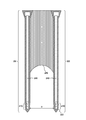
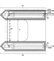
- FIG. 2 is an example of an external view of the sensor head 200 according to the first embodiment of the present technology.
- the sensor head 200 has probes 201 and 202.
- the length of each of the probes 201 and 202 is, for example, 75 to 150 millimeters (mm).
- the respective thicknesses (diameter or width of the probe cross section) of the probes 201 and 202 are, for example, 3 to 30 millimeters (mm).
- These probes 201 and 202 are arranged in a medium such as soil, and each has an antenna portion 210 capable of transmitting and receiving electromagnetic waves of a predetermined frequency between the probes 201 and 202.
- the probes 201 and 202 are embedded in the medium so that the distance between the respective antenna portions 210 becomes a predetermined value D.
- these probes are implanted in a medium in a generally vertical orientation. If the distance between the antenna portions 210 is D, their postures are not limited to the vertical postures.
- the antenna portion 210 is provided at or near the tip portions (in other words, the terminal portions) of the probes 201 and 202, and transmits and receives electromagnetic waves.
- the antenna portion 210 is provided at the tip portions of the probes 201 and 202, but the configuration is not limited to this. For example, it can be provided at the center position of the probes 201 and 202.
- the antenna unit 210 is composed of a small antenna formed in a size not to resonate the probes 201 and 202. As a result, it is possible to suppress a decrease in measurement accuracy due to resonance of the probes 201 and 202.
- the tips of the cables 308 and 309 (coaxial cable) in FIG. 1 are embedded in the probes 201 and 202, respectively.
- a part of this coaxial cable is opened and used as an antenna portion 210.
- the outer circumference of the portion of the coaxial cable other than the antenna portion 210 is covered with the electromagnetic wave absorber 240.
- the electromagnetic wave absorbing material 240 can suppress leakage of electromagnetic waves from a region other than the opening.
- Ni—Zn-based ferrite is mainly used as the electromagnetic wave absorbing material 240, but the present invention is not limited to this, and other high magnetic permeability materials such as sendust and permalloy may be used depending on the frequency of the electromagnetic wave EW and the like. .. Further, the electromagnetic wave absorbing material 240 may be omitted if necessary, or may be provided only on one of the probes 201 and 202.
- the size of the distance D between the antenna portions 210 is not particularly limited. If the distance D is too large, the attenuation of the electromagnetic wave EW propagating in the medium M becomes large, and there is a possibility that sufficient reception intensity cannot be obtained. On the other hand, if the distance D is too small, it may be technically difficult to observe. In consideration of these, the distance D is set to an appropriate value. For example, the distance D is 25 to 75 millimeters (mm).
- a spacer 260 is arranged between the probes 201 and 202 in order to define the distance between the antenna portions 210. Further, the outer circumferences of the probes 201 and 202 are each covered with an outer shell 225 having a thickness of 1 to 3 mm (mm) and isolated from the medium.
- the spacer 260 and the outer shell 225 are made of an electromagnetic wave transmitting material. Examples of the electromagnetic wave transmitting material include polymer materials, glass, and inorganic materials such as PTEF (PolyTEtraFluoroethylene).
- PC PolyCarbonate
- PES PolyEtherSulfone
- PEEK PolyEtherEtherKetone
- PSS PolyStyrene Sulfonic acid
- PMMA PolyMethylMethAcrylate
- PET PolyEthylene Terephthalate
- the thickness of the spacer 260 may be smaller than the size and thickness of the measuring unit 300 including the electronic circuit board and the semiconductor chip.
- the thickness of the spacer 260 is the thickness of the measuring unit 300. It may be smaller than the halfbeak, preferably less than 1/2, more preferably less than 1/3.
- the thickness of the spacer 260 is such that the measuring unit 300 extends.
- the thickness of the spacer 260 may be smaller than the thickness (diameter or width of the probe cross section) of at least one of the probes 201 and 202, preferably less than 1/2, and more. Preferably, it may be smaller than 1/3.
- the thickness of the spacer 260 may be, for example, 1 to 3 mm (mm).
- the thickness of the spacer 260 is made smaller than the thickness of the measuring unit 300, smaller than the length in one direction in which the measuring unit 300 extends, or the thickness of at least one of the probes 201 and 202 (
- the configuration of making it smaller than the diameter (or the width of the probe cross section) exhibits the effect unique to a moisture sensor that measures the propagation delay time of electromagnetic waves between antennas. Even if the spacer 260 is formed of an electromagnetic wave transmitting material, depending on the material, the electromagnetic wave radiated from the transmitting antenna may be reflected by the spacer and received by the receiving antenna, resulting in noise.
- the thickness of the spacer 260 By setting the thickness of the spacer 260 to the above configuration, it is possible to reduce the noise reflected by the spacer 260 as compared with the form not provided with this configuration.
- This effect of reducing noise by reducing the thickness of the spacer does not occur in the moisture sensor other than measuring the propagation delay time of electromagnetic waves between antennas, and the moisture measuring the propagation delay time of electromagnetic waves between antennas does not occur. This is an effect that occurs because it is a sensor.
- the distance d from the antenna portions (210 and 220) of the pair of probes (201 and 202) to the lower end of the spacer 260 is larger than the distance D between the antennas.
- the distance d is preferably larger than twice the distance D between the antennas.
- the distance d is larger than three times the distance D between the antennas and smaller than the respective lengths of the probes 201 and 202.
- this noise can be reduced by moving the spacer 260 away from the antenna.
- This "effect of reducing noise by moving the spacer 260 away from the antenna” does not occur with a moisture sensor other than the propagation delay measurement method between antennas, and as in this technology, the moisture sensor of the propagation delay measurement method between antennas That is why it occurs.
- the outer edge closer to the antenna portion (210 and 220) is illustrated in the figure. It has an arc shape.
- the noise received by the receiving antenna due to the microwaves radiated from the transmitting antenna being reflected by the spacer 260 can be further reduced.
- This "effect of reducing noise by making the spacer 260 arcuate" does not occur with a moisture sensor other than the propagation delay measurement method between antennas, but occurs because it is a moisture sensor with a propagation delay measurement method between antennas. It is something to do.
- FIG. 3 is a diagram showing an example of the antenna unit 210 and the equivalent circuit according to the first embodiment of the present technology.
- a is an enlarged view of the antenna portion 210.
- Reference numeral b in the figure is an example of an equivalent circuit of the antenna unit 210.
- the cable 308 (coaxial cable or the like) embedded in the probe 201 has a core wire portion 211 and a shield portion 212.
- the thickness and length of the cable are not particularly limited, and may be any thickness and length.
- the core wire portion 211 is made of copper wire and the shield portion 212 is made of copper pipe, but the shield portion 212 may be made of a mesh body of copper wire.
- a part near the tip of the cable 308 (coaxial cable, etc.) is opened, and the electrode portion 213 is attached.
- the antenna portions 210 of the probes 201 and 202 function as minute dipole antennas having a length of about 4 to 10 millimeters (millimeters).
- the opening has an opening shape such as a rectangle, a circle, an ellipse, or an oval.
- the long axis of the opening can be appropriately set according to the wavelength of the electromagnetic wave used.
- the equivalent circuit of the antenna unit 210 is represented by a circuit in which the resistor 511 and the fringe capacitances 512 and 513 are connected in parallel.
- the capacitance value of the fringe capacitance 512 is a value corresponding to the dielectric constant ⁇ c of the substance spreading inside the coaxial cable.
- the capacitance value of the fringe capacitance 513 is a value corresponding to the dielectric constant ⁇ * of the substance spreading around the electrode 513.
- the wave in the input signal is referred to as an "incident wave”
- the reflected wave of the incident wave is referred to as a "reflected wave”.
- the reflectance coefficient is the ratio of the complex amplitudes of the incident wave and the reflected wave.
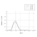
- FIG. 4 is a graph showing an example of the waveform of the impulse response of the reflection coefficient in the first embodiment of the present technology.
- the vertical axis represents the impulse response of the reflectance coefficient
- the horizontal axis represents time.
- the solid line curve shows the impulse response waveform when the medium is air
- the one-point chain line curve shows the impulse response waveform when the medium is water.
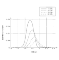
- FIG. 5 is a graph showing an example of the impulse response waveform of the reflectance coefficient in the comparative example in which the outer shell 225 is not provided.
- the vertical axis represents the impulse response of the reflectance coefficient
- the horizontal axis represents time.
- the solid line curve shows the impulse response waveform when the medium is air
- the one-point chain line curve shows the impulse response waveform when the medium is water.
- the fringing capacitance 512 is constant, so that the peak value of the impulse response does not fluctuate as illustrated in FIG. As a result, the round-trip delay time can be calculated with high accuracy.
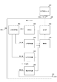
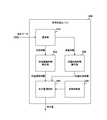
- FIG. 6 is a block diagram showing a configuration example of the measurement unit 300 according to the first embodiment of the present technology.
- the measuring unit 300 includes a directional coupler 310, a transmitter 320, an incident wave receiver 330, a reflected wave receiver 340, a transmitted wave receiver 350, a communication unit 360, and a control unit 370.
- a vector network analyzer is used as the measurement unit 300.
- the directional coupler 310 separates the electric signal transmitted through the cable 308 into an incident wave and a reflected wave.
- the incident wave is a wave of an electric signal transmitted by the transmitter 320
- the reflected wave is a wave reflected by the incident wave at the end of the probe 201.
- the directional coupler 310 supplies the incident wave to the incident wave receiver 330 and supplies the reflected wave to the reflected wave receiver 340.
- the transmitter 320 transmits an electric signal having a predetermined frequency as a transmission signal to the probe 201 via the directional coupler 310 and the cable 308.
- a CW (Continuous Wave) wave is used as the incident wave in the transmission signal.
- the transmitter 320 transmits a transmission signal, for example, in a frequency band of 1 to 9 gigahertz (GHz) by sequentially switching frequencies in steps of 50 megahertz (MHz).
- the incident wave receiver 330 receives the incident wave from the directional coupler 310.
- the reflected wave receiver 340 receives the reflected wave from the directional coupler 310.
- the transmitted wave receiver 350 receives the transmitted wave from the probe 202.
- the transmitted wave is an electromagnetic wave transmitted through the medium between the probes 201 and 202 converted into an electric signal by the probe 202.
- the incident wave receiver 330, the reflected wave receiver 340, and the transmitted wave receiver 350 perform orthogonal detection and AD (Analog to Digital) conversion on the received incident wave, reflected wave, and transmitted wave as received data. It is supplied to the control unit 370.
- AD Analog to Digital
- the incident wave receiver 330, the reflected wave receiver 340, and the transmitted wave receiver 350 are examples of the receivers described in the claims.
- the control unit 370 controls the transmitter 320 to transmit a transmission signal including an incident wave, and performs a process of obtaining a reflection coefficient and a transmission coefficient.
- the reflectance coefficient is the ratio of the complex amplitudes of the incident wave and the reflected wave as described above.
- the transmission coefficient is the ratio of the complex amplitudes of the incident wave and the transmitted wave.
- the control unit 370 supplies the obtained reflection coefficient and transmission coefficient to the communication unit 360.
- the communication unit 360 transmits data indicating the reflection coefficient and the transmission coefficient as measurement data to the signal processing unit 400 via the signal line 409.
- the frequency characteristics of the directional coupler 310, the transmitter 320, and the receiver are calibrated before the measurement. Is being executed.
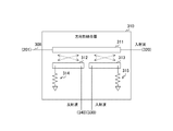
- FIG. 7 is a diagram showing a configuration example of the directional coupler 310 according to the first embodiment of the present technology.
- the directional coupler 310 includes transmission lines 311, 312 and 313 and terminating resistors 314 and 315.
- the directional coupler 310 can be mounted, for example, by a bridge coupler suitable for miniaturization.
- the transmission line 311 is connected to the transmitter 320, and the other end is connected to the probe 201 via the cable 308.
- the transmission line 312 is shorter than the transmission line 311 and is a line that is electromagnetically coupled to the transmission line 311.
- a terminating resistor 314 is connected to one end of the transmission line 312, and the other end is connected to the reflected wave receiver 340.
- the transmission line 313 is shorter than the transmission line 311 and is a line that is electromagnetically coupled to the transmission line 311.
- a terminating resistor 315 is connected to one end of the transmission line 313, and the other end is connected to the incident wave receiver 330.
- the directional coupler 310 separates the electric signal into an incident wave and a reflected wave, and supplies the electric signal to the incident wave receiver 330 and the reflected wave receiver 340.
- FIG. 8 is a circuit diagram showing a configuration example of the transmitter 320 and the receiver according to the first embodiment of the present technology.
- a is a circuit diagram showing a configuration example of the transmitter 320
- b in the figure is a circuit diagram showing a configuration example of the incident wave receiver 330.
- c is a circuit diagram showing a configuration example of the reflected wave receiver 340
- d in the figure is a circuit diagram showing a configuration example of the transmitted wave receiver 350.
- the transmitter 320 includes a transmission signal oscillator 322 and a driver 321.
- the transmission signal oscillator 322 generates an electric signal as a transmission signal under the control of the control unit 370.
- the driver 321 outputs a transmission signal to the directional coupler 310.
- This transmission signal S (t) is expressed by, for example, the following equation.
- S (t)
- t represents time and the unit is, for example, nanoseconds (ns).
- cos () indicates a cosine function.
- f indicates a frequency, and the unit is, for example, hertz (Hz).
- ⁇ represents a phase, and the unit is, for example, radian (rad).
- the incident wave receiver 330 includes a mixer 331, a bandpass filter 332, and an analog-digital converter 333.
- the mixer 331 performs orthogonal detection by mixing two local signals having a phase difference of 90 degrees and a transmission signal. By this orthogonal detection, a complex amplitude composed of the in-phase component I I and the orthogonal component Q I is obtained. These in-phase component I I and orthogonal component Q I are represented by, for example, the following equations.
- the mixer 331 supplies the complex amplitude to the analog-to-digital converter 333 via the bandpass filter 332.
- I I
- Q I
- sin () represents a sine function.
- the bandpass filter 332 passes components in a predetermined frequency band.
- the analog-to-digital converter 333 performs AD conversion.
- the analog-digital converter 333 generates data showing complex amplitude by AD conversion and supplies it to the control unit 370 as received data.
- the reflected wave receiver 340 includes a mixer 341, a bandpass filter 342, and an analog-to-digital converter 343.
- the configuration of the mixer 341, the bandpass filter 342, and the analog-to-digital converter 343 is the same as that of the mixer 331, the bandpass filter 332, and the analog-to-digital converter 333.
- Reflected wave receiver 340, the reflected wave quadrature detection to obtain the complex amplitude consisting of in-phase component I R and the quadrature component Q R, and supplies the received data indicating the complex amplitude to the control unit 370.
- the transmitted wave receiver 350 includes a receiver 351, a local signal oscillator 352, a mixer 353, a bandpass filter 354, and an analog-to-digital converter 355.
- the configuration of the mixer 353, the bandpass filter 354, and the analog-to-digital converter 355 is the same as that of the mixer 331, the bandpass filter 332, and the analog-to-digital converter 333.
- the receiver 351 receives an electric signal including a transmitted wave via the cable 309 and outputs it to the mixer 353.
- the local signal oscillator 352 generates two local signals that are 90 degrees out of phase.
- Transmitted wave receiver 350 the transmitted wave quadrature detection to obtain the complex amplitude consisting of in-phase component I T and the quadrature component Q T, to the control unit 370 the data indicating the complex amplitude as received data.
- circuits of the transmitter 320 and the receiver are not limited to the circuits illustrated in the figure as long as they can transmit and receive incident waves and the like.
- FIG. 9 is a block diagram showing a configuration example of the control unit 370 according to the first embodiment of the present technology.
- the control unit 370 includes a transmission control unit 371, a reflection coefficient calculation unit 372, and a transmission coefficient calculation unit 373.
- the transmission control unit 371 controls the transmitter 320 to transmit a transmission signal.
- the reflection coefficient calculation unit 372 calculates the reflection coefficient ⁇ for each frequency.
- the reflectance coefficient calculation unit 372 calculates the reflectance coefficient by Equation 1 for each of N (N is an integer) frequencies f 1 to f N. These N-number of the reflection coefficient and gamma 1 or gamma N. The reflection coefficient calculation unit 372 supplies those reflection coefficients to the communication unit 360.
- the transmission coefficient calculation unit 373 calculates the transmission coefficient T for each frequency.
- the transmission coefficient calculation unit 373 calculates the transmission coefficient by Equation 2 for each of the N frequencies f 1 to f N. Let these N reflection coefficients be T 1 to TN . The transmission coefficient calculation unit 373 supplies those transmission coefficients to the signal processing unit 400 via the communication unit 360.
- FIG. 10 is a block diagram showing a configuration example of the signal processing unit 400 according to the first embodiment of the present technology.
- the signal processing unit 400 includes a communication unit 410, a round-trip delay time calculation unit 420, a propagation transmission time calculation unit 430, a water content measurement unit 440, and a coefficient holding unit 450.
- the communication unit 410 receives the measurement data from the measurement unit 300.
- the communication unit 410 supplies the reflection coefficients ⁇ 1 to ⁇ N in the measurement data to the reciprocating delay time calculation unit 420, and supplies the transmission coefficients T 1 to TN in the measurement data to the propagation transmission time calculation unit 430.
- the reciprocating delay time calculation unit 420 calculates the time for the electric signal to reciprocate in the cable 308 as the reciprocating delay time based on the reflection coefficient.
- the round-trip delay time calculation unit 420 obtains the impulse response h ⁇ (t) by performing an inverse Fourier transform on the reflection coefficients ⁇ 1 to ⁇ N. Then, the round-trip delay time calculation unit 420 obtains the time difference between the timing of the peak value of the impulse response h ⁇ (t) and the transmission timing of the CW wave as the round-trip delay time ⁇ 11 , and supplies the time difference to the water content measuring unit 440.
- the propagation transmission time calculation unit 430 calculates the time for the electromagnetic wave and the electric signal to propagate and transmit between the medium and the cables 308 and 309 as the propagation transmission time based on the transmission coefficient.
- the propagation transmission time calculation unit 430 obtains an impulse response h T (t) by performing an inverse Fourier transform on the transmission coefficients T 1 to TN . Then, the propagation transmission time calculation unit 430 obtains the time difference between the timing of the peak value of the impulse response h T (t) and the transmission timing of the CW wave as the propagation transmission time ⁇ 21 , and supplies the time difference to the water content measurement unit 440.
- the water content measuring unit 440 measures the water content based on the round-trip delay time ⁇ 11 and the propagation transmission time ⁇ 21 .
- the water content measuring unit 440 first calculates the propagation delay time ⁇ d from the round-trip delay time ⁇ 11 and the propagation transmission time ⁇ 21 .
- the propagation delay time is the time for the electromagnetic wave to propagate through the medium between the probes 201 and 202.
- the units of the round-trip delay time ⁇ 11 , the propagation transmission time ⁇ 21, and the propagation delay time ⁇ d are, for example, nanoseconds (ns).
- the water content measuring unit 440 reads out the coefficients a and b indicating the relationship between the water content and the propagation delay time ⁇ d from the coefficient holding unit 450, and the propagation delay time ⁇ d calculated by the equation 3 is expressed in the following equation. Substitute and measure the water content x. Then, the water content measuring unit 440 outputs the measured water content to an external device or device as needed.
- ⁇ d a ⁇ x + b ⁇ ⁇ ⁇ Equation 4
- the unit of the water content x is, for example, a volume percentage (%).
- the coefficient holding unit 450 holds the coefficients a and b.
- a non-volatile memory or the like is used as the coefficient holding unit 450.
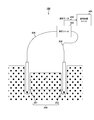
- FIG. 11 is a diagram for explaining a propagation path and a transmission path of electromagnetic waves and electric signals in the first embodiment of the present technology.
- the transmitter 320 transmits an electric signal including an incident wave to the probe 201 as a transmission signal via a cable 308 whose tip is embedded in the probe 201.
- the incident wave is reflected at the end of the probe 201, and the reflected wave is received by the reflected wave receiver 340.
- electric signals including incident waves and reflected waves reciprocate in the cable 308.
- the thick solid arrow in the figure indicates the path of the electric signal reciprocating through the cable 308.
- the time for the electric signal to reciprocate on this path corresponds to the reciprocating delay time ⁇ 11 .
- the electric signal including the incident wave is converted into an electromagnetic wave EW by the probe 201 and transmitted (in other words, propagated) through the medium between the probes 201 and 202.
- the probe 202 converts the electromagnetic wave EW into an electric signal.
- the transmitted wave receiver 350 receives the transmitted wave in the electric signal via the cable 309. That is, the electric signal including the incident wave is transmitted through the cable 308, is converted into the electromagnetic wave EW and propagates through the medium, is converted into the electric signal including the transmitted wave, and is transmitted through the cable 309.
- the thick dotted arrow in the figure indicates the path through which the electromagnetic wave and the electrical signal (incident wave and transmitted wave) propagate and transmit between the medium and the cables 308 and 309.
- the time for electromagnetic waves and electrical signals to propagate and transmit along this path corresponds to the propagation transmission time ⁇ 21 .
- the control unit 370 in the measuring unit 300 obtains the reflection coefficient ⁇ and the transmission coefficient T by the equations 1 and 2. Then, the signal processing unit 400 obtains the round-trip delay time ⁇ 11 and the propagation transmission time ⁇ 21 from the reflection coefficient ⁇ and the transmission coefficient T.
- the path from the transmission of the incident wave to the reception of the transmitted wave includes the medium and the cables 308 and 309. Therefore, the propagation delay time ⁇ d at which the electromagnetic wave propagates through the medium is obtained by the difference between the propagation transmission time ⁇ 21 and the delay time during which the electric signal transmits the cables 308 and 309.
- the delay time for transmitting the cable 308 and the delay time for transmitting the cable 309 are the same.
- the total delay time for the electrical signal to transmit the cables 308 and 309 is equal to the round trip delay time ⁇ 11 for the round trip cable 308. Therefore, the equation 3 holds, and the signal processing unit 400 can calculate the propagation delay time ⁇ d by the equation 3.
- the signal processing unit 400 calculates the propagation delay time from the obtained round-trip delay time ⁇ 11 and the propagation transmission time ⁇ 21 , and measures the amount of water contained in the medium from the propagation delay time and the coefficients a and b. I do.
- the signal processing unit 400 is an example of the processing unit described in the claims.
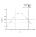
- FIG. 12 is a graph showing an example of the waveform of the impulse response of the reflection coefficient in the first embodiment of the present technology.
- the vertical axis is the impulse response of the reflectance coefficient
- the horizontal axis is time.
- the measuring device 100 obtains the impulse response of the reflectance coefficient.
- the respective water content is 0.0, 10.1, 19.7, and 32.9 volume percent (%).
- the peak value of the reflectance coefficient does not change even if the water content changes. That is, the round-trip delay time is constant. This is because, as described above, the probes 201 and 202 are separated by the outer shell 225.
- FIG. 13 is a graph showing an example of the waveform of the impulse response of the transmission coefficient in the first embodiment of the present technology.
- the vertical axis is the impulse response of the transmission coefficient
- the horizontal axis is time.
- the medium to be measured is four kinds of Toyoura standard sand similar to those in FIG.
- FIG. 14 is a graph showing an example of the relationship between the round-trip delay time, the propagation transmission time, and the water content in the first embodiment of the present technology.
- the vertical axis shows the round-trip delay time or the propagation transmission time
- the horizontal axis shows the water content.
- the dotted line in FIG. 14 shows the relationship between the round-trip delay time obtained from FIG. 12 and the water content.
- the solid line in FIG. 14 shows the relationship between the propagation transmission time and the water content obtained from FIG.
- the reciprocating delay time is constant regardless of the amount of water. On the other hand, as the amount of water increases, the propagation transmission delay time becomes longer.
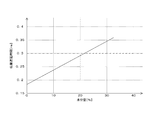
- FIG. 15 is a graph showing an example of the relationship between the propagation delay time and the water content in the first embodiment of the present technology.
- the vertical axis shows the propagation delay time
- the horizontal axis shows the water content.
- the straight line in the figure is obtained by obtaining the difference between the propagation transmission time and the round-trip delay time for each water content in FIG.
- Equation 4 holds.
- the coefficient a in Equation 4 is the slope of a straight line in the figure, and the coefficient b is an intercept.
- FIG. 16 is a block diagram showing a configuration example of a measuring device in which cables 308 and 309 are further extended according to the first embodiment of the present technology. By lengthening the cables 308 and 309, the measurement unit 300 and the signal processing unit 400 can be located farther than the probes 201 and 202.
- the longer the cables 308 and 309 the larger the fluctuation of the round-trip delay time due to the temperature change. Therefore, if the measuring device 100 measures the water content with the reciprocating delay time as a fixed value, the error between the true value and the fixed value may increase and the measurement accuracy of the water content may decrease.
- the measuring device 100 receives the reflected wave and calculates the round-trip delay time from the reflection coefficient. Therefore, even if the reciprocating delay time fluctuates due to the temperature change, the measuring device 100 can obtain the value at the time of the fluctuation. Therefore, the measurement accuracy of the water content can be improved as compared with the case where the round-trip delay time is set to a fixed value.
- FIG. 17 is a flowchart showing an example of the operation of the measuring device 100 according to the first embodiment of the present technology. The operation in the figure is started, for example, when a predetermined application for measuring the amount of water is executed.
- the pair of probes 201 and 202 transmit and receive electromagnetic waves (step S901).
- the measuring unit 300 calculates the reflection coefficient from the incident wave and the reflected wave (step S902), and calculates the transmission coefficient from the incident wave and the transmitted wave (step S903).
- the signal processing unit 400 calculates the round-trip delay time from the reflection coefficient (step S904), and calculates the propagation transmission time from the transmission coefficient (step S905).
- the signal processing unit 400 calculates the propagation delay time from the round-trip delay time and the propagation transmission time (step S906), and calculates the water content from the propagation delay time and the coefficients a and b (step S907).
- the measuring device 100 ends the operation for measurement.
- the measuring device 100 obtains the round-trip delay time for the electric signal to reciprocate the cable 308, and measures the water content from the round-trip delay time. Even when the time fluctuates, the water content can be measured with high accuracy.
- Second Embodiment> In the first embodiment described above, the measurement unit 300 and the signal processing unit 400 are mounted on different semiconductor chips. However, in this configuration, it is necessary to provide an interface for communication between semiconductor chips, which may increase the circuit scale of the measuring device 100.
- the measuring device 100 of the second embodiment is different from the first embodiment in that the functions of the measuring unit 300 and the signal processing unit 400 are realized by a single semiconductor chip.
- FIG. 18 is a block diagram showing a configuration example of the measuring device 100 according to the second embodiment of the present technology.
- the measuring device 100 of the second embodiment is different from the first embodiment in that the measuring unit 301 is provided instead of the measuring unit 300 and the signal processing unit 400.
- the measurement unit 301 has the function of the signal processing unit 400 in addition to the function of the measurement unit 300 of the first embodiment.
- FIG. 19 is a block diagram showing a configuration example of the measurement unit 301 according to the second embodiment of the present technology.
- the measurement unit 301 of the second embodiment is different from the first embodiment in that the signal processing unit 380 is provided instead of the communication unit 360.
- the configuration of the signal processing unit 380 is the same as that of the signal processing unit 400 of the first embodiment.
- the function of the control unit 370 is realized by, for example, a DSP (Digital Signal Processing) circuit.
- DSP Digital Signal Processing
- the measurement unit 301 shall be mounted on a single semiconductor chip.
- the functions of the measurement unit 300 and the signal processing unit 400 can be realized by a single semiconductor chip. Therefore, an interface (communication unit 360 or the like) for communicating between semiconductor chips is not required, and the circuit scale of the measuring device 100 can be reduced.
- the functions of the measurement unit 300 and the signal processing unit 400 are mounted on a single semiconductor chip, as compared with the case where they are mounted on different semiconductor chips, The circuit scale of the measuring device 100 can be reduced.
- the measurement unit 300 and the signal processing unit 400 are connected by wire by a signal line 409, but in this configuration, the signal processing unit 400 is arranged at a remote location away from the measurement location. Becomes difficult.
- the measurement unit 300 of the third embodiment is different from the first embodiment in that the measurement data is wirelessly transmitted.
- FIG. 20 is a block diagram showing a configuration example of a measurement system according to a third embodiment of the present technology.
- the measurement system of the third embodiment includes a sensor device 110 and a signal processing unit 400.
- the sensor device 110 of the third embodiment includes a measurement unit 302 instead of the measurement unit 300.
- the communication unit 360 of the measurement unit 302 differs from the first embodiment in that the measurement data is wirelessly transmitted to the signal processing unit 400 via the antenna 390.
- the signal processing unit 400 is connected to the network of the base station or the Internet, and receives the measurement data wirelessly transmitted via them by wire or wirelessly.
- the signal processing unit 400 can be arranged at a remote location away from the measurement point.
- the signal processing unit 400 can be arranged at a remote location.
- the water content is measured under the assumption that the delay time for transmitting the electric signal to each of the cables 308 and 309 is the same. However, if the lengths of the cables 308 and 309 are different, the delay times thereof will be different values, which may break the premise and cause a measurement error.
- the measuring device 100 of the fourth embodiment is different from the first embodiment in that the reciprocating delay time of the cable 308 and the reciprocating delay time of the cable 309 are both obtained and the water content is measured.
- FIG. 21 is a block diagram showing a configuration example of the measurement unit 300 according to the fourth embodiment of the present technology.
- the measuring unit 300 of the fourth embodiment includes directional couplers 310 and 391, transmitters 320 and 393, incident wave receivers 330 and 394, transmitted wave / reflected wave receivers 392 and 395, and the like. It includes a communication unit 360 and a control unit 370.
- the transmitter 320 transmits the incident wave I1 via the cable 308.
- the transmitter 393 transmits the incident wave I2 via the cable 309.
- the control unit 370 controls the transmitters 320 and 393 to transmit the incident waves I1 and I2 in order.
- the incident wave receiver 330 receives the incident wave I1 when the incident wave I1 is transmitted.
- the incident wave receiver 394 receives the incident wave I2 when the incident wave I2 is transmitted.
- the directional coupler 310 separates the electric signal of the cable 308 into an incident wave and a reflected wave.
- the directional coupler 310 separates the electric signal of the cable 308 into the incident wave I1 and the reflected wave R1 corresponding to the incident wave I1.
- the directional coupler 310 outputs the transmitted wave Tr1 corresponding to the incident wave I2.
- the directional coupler 391 separates the electric signal of the cable 309 into an incident wave and a reflected wave.
- the directional coupler 391 separates the electric signal of the cable 308 into the incident wave I2 and the reflected wave R2 corresponding to the incident wave I2.
- the directional coupler 391 outputs the transmitted wave Tr2 corresponding to the incident wave I1.
- the transmitted wave / reflected wave receiver 392 receives the transmitted wave and the reflected wave in order.
- the transmitted wave / reflected wave receiver 392 receives the reflected wave R1 from the directional coupler 310 when the incident wave I1 is transmitted, and when the incident wave I2 is transmitted, the directional coupler 310 Receives the transmitted wave Tr1 from.
- the transmitted wave / reflected wave receiver 395 receives the transmitted wave and the reflected wave in order.
- the transmitted wave / reflected wave receiver 395 receives the transmitted wave Tr2 from the directional coupler 391 when the incident wave I1 is transmitted, and when the incident wave I2 is transmitted, the directional coupler 391 The reflected wave R2 from is received.
- the incident waves I1 and I2 are examples of the first and second incident waves described in the claims, and the reflected waves R1 and R2 are the first and second reflections described in the claims. This is an example of a wave.
- the transmitted waves Tr1 and Tr2 are examples of the first and second transmitted waves described in the claims.
- the directional couplers 310 and 391 are examples of the first and second directional couplers described in the claims, and the transmitters 320 and 393 are examples of the first and second transmitters.
- the transmitted wave / reflected wave receivers 392 and 395 are examples of the first and second receivers described in the claims.
- Control unit 370 from each of the complex amplitude of the incident wave I1 and reflected wave R1 in the same manner as in the first embodiment, to calculate the reflection coefficient gamma 11, each of the complex amplitude of the incident wave I1 and transmitted waves Tr2 From, the transmission coefficient T 21 is calculated. Further, the control unit 370 calculates the reflection coefficient ⁇ 22 from the complex amplitudes of the incident wave I2 and the reflected wave R2 in the same manner as in the first embodiment, and calculates the reflection coefficient ⁇ 22 of each of the incident wave I2 and the transmitted wave Tr1. The transmission coefficient T 12 is calculated from the complex amplitude.
- the signal processing unit 400 in the subsequent stage calculates the round-trip delay time ⁇ 11 and the propagation transmission time ⁇ 12 from the reflection coefficient ⁇ 11 and the transmission coefficient T 12 in the same manner as in the first embodiment. Further, the signal processing unit 400 calculates the round-trip delay time ⁇ 22 and the propagation transmission time ⁇ 21 from the reflection coefficient ⁇ 22 and the transmission coefficient T 12 in the same manner as in the first embodiment.
- the signal processing unit 400 calculates the propagation delay time ⁇ d by the following equation.
- ⁇ d ( ⁇ 21 + ⁇ 12- ⁇ 11- ⁇ 22 ) / 2 ⁇ ⁇ ⁇ Equation 5
- the signal processing unit 400 measures the water content by substituting the propagation delay time ⁇ d calculated by the equation 5 into the equation 4.
- the round-trip delay times ⁇ 11 and ⁇ 22 are examples of the first and second round-trip delay times described in the claims.
- the delay times for transmitting electrical signals through the cables may differ from each other.
- the measurement error due to the difference in the lengths of the cables 308 and 309 is obtained by performing the calculation using the round-trip delay time ⁇ 22 in addition to the round-trip delay time ⁇ 11 according to Equation 5. Can be reduced.
- the water content is measured by using the round-trip delay time ⁇ 11 corresponding to the cable 308 and the round-trip delay time ⁇ 22 corresponding to the cable 309.
- the measurement error caused by the difference in the lengths of those cables can be reduced.
- the processing procedure described in the above-described embodiment may be regarded as a method having these series of procedures, and as a program for causing a computer to execute these series of procedures or as a recording medium for storing the program. You may catch it.
- a recording medium for example, a CD (Compact Disc), MD (MiniDisc), DVD (Digital Versatile Disc), memory card, Blu-ray Disc (Blu-ray (registered trademark) Disc) and the like can be used.
- the present technology can have the following configurations.
- a transmitter that transmits an electric signal including an incident wave to one of a pair of probes in which a cable is embedded via the cable.
- a receiver that receives the reflected wave reflected by the incident wave from the pair of probes and the transmitted wave transmitted through the medium between the pair of probes via the cable.
- the reciprocating delay time which is the time for the electric signal to reciprocate in the cable, is obtained, and the reciprocating delay time is based on the reciprocating delay time and the propagation transmission time, which is the time for electromagnetic waves and the electric signal to propagate and transmit the medium and the cable.
- a measuring device including a processing unit that performs a process of measuring the amount of water contained in the medium.
- the measuring device according to (1) above further comprising an outer shell that separates the pair of probes from the medium.
- the outer shell is made of an electromagnetic wave transmitting material.
- the measuring device according to (3) above further comprising a spacer that keeps the distance between the pair of probes constant.
- the measuring device according to (4) above, wherein the spacer is made of an electromagnetic wave transmitting material.
- the outer edge has an arc shape.
- the distance from the antenna portion of each of the pair of probes to the lower end of the spacer is larger than the distance between the antennas, which is the distance between the antenna portions. Preferably, it is greater than twice the distance between the antennas. More preferably, it is larger than three times the distance between the antennas.
- the measuring device according to (6) above which is smaller than the length of the probe.
- the measuring device according to any one of (1) to (7), wherein the processing unit obtains the reciprocating delay time and the propagation transmission time based on the reflection coefficient and the transmission coefficient.
- the control unit and the processing unit are provided on a predetermined semiconductor chip.
- the control unit is provided on a predetermined semiconductor chip, and the processing unit is provided on a semiconductor chip different from the semiconductor chip.
- the measuring apparatus according to any one of (8) to (11), further comprising a directional coupler that separates an electric signal transmitted through the cable into the incident wave and the reflected wave.
- the receiver is An incident wave receiver that receives the incident wave and A reflected wave receiver that receives the reflected wave and The measuring device according to (12) above, which includes a transmitted wave receiver that receives the transmitted wave.
- the incident waves include first and second incident waves having different directions from each other.
- the reflected wave includes a first reflected wave corresponding to the first incident wave and a second reflected wave corresponding to the second incident wave.
- the transmitted wave includes a second transmitted wave corresponding to the first incident wave and a first transmitted wave corresponding to the second incident wave.
- the directional coupler includes a first directional coupler that separates the electric signal into the first incident wave and the first reflected wave, and the electric signal is separated into the second incident wave and the first reflected wave. Includes a second directional coupler that separates into two reflected waves
- the transmitter includes a first transmitter that transmits the first incident wave and a second transmitter that transmits the second incident wave.
- the receiver receives a first receiver that sequentially receives the first reflected wave and the first transmitted wave, and a second receiver that sequentially receives the second reflected wave and the second transmitted wave.
- the round-trip delay time includes a first round-trip delay time corresponding to one of the pair of probes and a second round-trip delay time corresponding to the other of the pair of probes.
- the processing unit obtains the first round trip delay time from the first incident wave and the first reflected wave, and the second round trip from the second incident wave and the second reflected wave.
- the measuring device determines the delay time.
- the processing unit obtains a propagation delay time, which is a time for the electromagnetic wave to propagate through the medium, from the round-trip delay time and the propagation transmission time, and measures the amount of water according to the propagation delay time (1). ) To (15).
- the processing unit holds a predetermined coefficient indicating the relationship between the propagation delay time and the water content, and measures the water content from the obtained propagation delay time and the coefficient (16). ) The measuring device described.
- a transmitter that transmits an electric signal including an incident wave to one of a pair of probes to which a cable is connected to each of the cables.
- a receiver that receives the reflected wave reflected by the incident wave from the pair of probes and the transmitted wave transmitted through the medium between the pair of probes via the cable.
- a control unit that controls the transmission of the incident wave and a control unit that performs a process of obtaining the ratio of the complex amplitudes of the incident wave and the reflected wave as a reflection coefficient.
- the reciprocating delay time which is the time for the electric signal to reciprocate in the cable, is obtained from the reflection coefficient, and the reciprocating delay time and the propagation transmission time, which is the time for the electromagnetic wave and the electric signal to propagate and transmit the medium and the cable.
- a measurement system including a processing unit that performs a process of measuring the amount of water contained in the medium based on the above. (19) A transmission procedure for transmitting an electric signal including an incident wave to one of a pair of probes in which a cable is embedded via the cable. A reception procedure for receiving the reflected wave reflected by the incident wave from the pair of probes and the transmitted wave transmitted through the medium between the pair of probes via the cable.
- the reciprocating delay time which is the time for the electric signal to reciprocate in the cable, is obtained, and the reciprocating delay time is based on the reciprocating delay time and the propagation transmission time, which is the time for the electromagnetic wave and the electric signal to propagate and transmit the medium and the cable.
- a measurement method including a processing procedure for performing a process for measuring the amount of water contained in a medium.
Landscapes
- Life Sciences & Earth Sciences (AREA)
- Physics & Mathematics (AREA)
- Health & Medical Sciences (AREA)
- Chemical & Material Sciences (AREA)
- Immunology (AREA)
- Analytical Chemistry (AREA)
- Pathology (AREA)
- General Physics & Mathematics (AREA)
- General Health & Medical Sciences (AREA)
- Biochemistry (AREA)
- Engineering & Computer Science (AREA)
- Electromagnetism (AREA)
- Environmental & Geological Engineering (AREA)
- Medicinal Chemistry (AREA)
- Food Science & Technology (AREA)
- General Life Sciences & Earth Sciences (AREA)
- Geology (AREA)
- Remote Sensing (AREA)
- Geophysics And Detection Of Objects (AREA)
- Investigating Or Analyzing Materials By The Use Of Ultrasonic Waves (AREA)
- Measurement Of Resistance Or Impedance (AREA)
Abstract
Description
1.第1の実施の形態(往復遅延時間および伝搬伝送時間を求める例)
2.第2の実施の形態(1つの半導体チップにより往復遅延時間および伝搬伝送時間を求める例)
3.第3の実施の形態(無線通信を行い、往復遅延時間および伝搬伝送時間を求める例)
4.第4の実施の形態(送信方向を変えて往復遅延時間および伝搬伝送時間を求める例)
[測定装置の構成例]
図1は、本技術の第1の実施の形態における測定装置100の一構成例を示すブロック図である。この測定装置100は、媒質Mに含まれる水分量を測定するものであり、センサ装置110と、信号処理ユニット400とを有する。媒質Mとしては、例えば、農作物を育成するための土壌が想定される。
図2は、本技術の第1の実施の形態におけるセンサヘッド200の外観図の一例である。センサヘッド200は、プローブ201および202を有する。プローブ201および202のそれぞれの長さは、例えば、75乃至150ミリメートル(mm)である。プローブ201および202のそれぞれの太さ(直径、あるいは、プローブ断面の幅)は、例えば、3乃至30ミリメートル(mm)である。これらのプローブ201および202は、土壌等の媒質の中に配置され、プローブ201および202の間で所定周波数の電磁波を送受信することが可能なアンテナ部210をそれぞれ有する。
図3は、本技術の第1の実施の形態におけるアンテナ部210および等価回路の一例を示す図である。同図におけるaは、アンテナ部210の拡大図である。同図におけるbは、アンテナ部210の等価回路の一例である。
図7は、本技術の第1の実施の形態における方向性結合器310の一構成例を示す図である。この方向性結合器310は、伝送線路311、312および313と、終端抵抗314および315とを備える。この方向性結合器310は、例えば、小型化に好適なブリッジカップラーにより実装することができる。
図8は、本技術の第1の実施の形態における送信機320および受信機の一構成例を示す回路図である。同図におけるaは、送信機320の一構成例を示す回路図であり、同図におけるbは、入射波受信機330の一構成例を示す回路図である。同図におけるcは、反射波受信機340の一構成例を示す回路図であり、同図におけるdは、透過波受信機350の一構成例を示す回路図である。
S(t)=|A|cos(2πft+θ)
上式において、tは、時刻を表し、単位は、例えば、ナノ秒(ns)である。|A|は、送信信号の振幅を示す。cos()は、余弦関数を示す。fは、周波数を示し、単位は例えば、ヘルツ(Hz)である。θは、位相を表し、単位は、例えば、ラジアン(rad)である。
II=|A|cos(θ)
QI=|A|sin(θ)
上式において、sin()は、正弦関数を示す。
図9は、本技術の第1の実施の形態における制御部370の一構成例を示すブロック図である。この制御部370は、送信制御部371、反射係数算出部372および透過係数算出部373を備える。
Γ=(IR+jQR)/(II+jQI) ・・・式1
上式において、jは、虚数単位である。
T=(IT+jQT)/(II+jQI) ・・・式2
図10は、本技術の第1の実施の形態における信号処理ユニット400の一構成例を示すブロック図である。この信号処理ユニット400は、通信部410、往復遅延時間算出部420、伝搬伝送時間算出部430、水分量測定部440および係数保持部450を備える。
τd=τ21-τ11 ・・・式3
上式において、往復遅延時間τ11、伝搬伝送時間τ21および伝搬遅延時間τdのそれぞれの単位は、例えば、ナノ秒(ns)である。
τd=a・x+b ・・・式4
上式において、水分量xの単位は、例えば、体積パーセント(%)である。
図17は、本技術の第1の実施の形態における測定装置100の動作の一例を示すフローチャートである。同図における動作は、例えば、水分量を測定するための所定のアプリケーションが実行されたときに開始される。
上述の第1の実施の形態では、測定ユニット300と信号処理ユニット400とを互いに異なる半導体チップに実装していた。しかし、この構成では、半導体チップ間の通信のためのインターフェースを設ける必要があり、その分、測定装置100の回路規模が増大するおそれがある。この第2の実施の形態の測定装置100は、測定ユニット300および信号処理ユニット400のそれぞれの機能を単体の半導体チップで実現する点において第1の実施の形態と異なる。
上述の第1の実施の形態では、測定ユニット300と信号処理ユニット400とを信号線409により有線接続していたが、この構成では、信号処理ユニット400を測定個所から離れた遠隔地に配置することが困難となる。この第3の実施の形態の測定ユニット300は、測定データを無線送信する点において第1の実施の形態と異なる。
上述の第1の実施の形態では、ケーブル308および309のそれぞれを電気信号が伝送する遅延時間が同一であると仮定して、その前提の下で水分量を測定していた。しかし、ケーブル308および309のそれぞれの長さが異なる場合には、それらの遅延時間が異なる値になり、前提が崩れて測定誤差が生じるおそれがある。この第4の実施の形態の測定装置100は、ケーブル308の往復遅延時間とケーブル309の往復遅延時間とを両方とも求めて、水分量を測定する点において第1の実施の形態と異なる。
τd=(τ21+τ12-τ11-τ22)/2 ・・・式5
(1)各々にケーブルが埋め込まれた一対のプローブの一方へ前記ケーブルを介して入射波を含む電気信号を送信する送信機と、
前記一対のプローブの前記一方で前記入射波が反射した反射波と前記一対のプローブの間の媒質を透過した透過波とを前記ケーブルを介して受信する受信機と、
前記ケーブルを前記電気信号が往復する時間である往復遅延時間を求めて前記往復遅延時間と前記媒質および前記ケーブルを電磁波および前記電気信号が伝搬および伝送する時間である伝搬伝送時間とに基づいて前記媒質に含まれる水分量を測定する処理を行う処理部と
を具備する測定装置。
(2)前記一対のプローブを前記媒質から隔離する外殻をさらに具備する
前記(1)記載の測定装置。
(3)前記外殻は、電磁波透過材料で形成されている
前記(2)記載の測定装置。
(4)前記一対のプローブの間隔を一定に保持するスペーサをさらに具備する
前記(3)記載の測定装置。
(5)前記スペーサは、電磁波透過材料で形成されている
前記(4)記載の測定装置。
(6)前記スペーサの外縁であって、前記一対のプローブの間に延在する該外縁のうち、前記一対のプローブのそれぞれのアンテナ部に近い方の該外縁は、円弧状になっている
前記(5)記載の測定装置。
(7)前記一対のプローブのそれぞれの前記アンテナ部から前記スペーサの下端までの距離は、前記アンテナ部の間の距離であるアンテナ間距離よりも大きく、
好ましくは前記アンテナ間距離の2倍よりも大きく、
より好ましくは、前記アンテナ間距離の3倍よりも大きく、
前記プローブの長さよりも小さい
前記(6)記載の測定装置。
(8)前記入射波を送信させる制御と前記入射波および前記反射波のそれぞれの複素振幅の比を反射係数として求める処理と前記入射波および前記透過波のそれぞれの複素振幅の比を透過係数として求める処理とを行う制御部をさらに具備し、
前記処理部は、前記反射係数および前記透過係数に基づいて前記往復遅延時間および前記伝搬伝送時間を求める
前記(1)から(7)のいずれかに記載の測定装置。
(9)前記制御部と前記処理部とは所定の半導体チップに設けられる
前記(1)から(8)のいずれかに記載の測定装置。
(10)前記制御部は、所定の半導体チップに設けられ
前記処理部は前記半導体チップと異なる半導体チップに設けられる
前記(8)記載の測定装置。
(11)前記反射係数および前記透過係数を前記処理部に無線送信する通信部をさらに具備する
前記(8)記載の測定装置。
(12)前記ケーブルを伝送する電気信号を前記入射波と前記反射波に分離する方向性結合器をさらに具備する
前記(8)から(11)のいずれかに記載の測定装置。
(13)前記受信機は、
前記入射波を受信する入射波受信機と、
前記反射波を受信する反射波受信機と、
前記透過波を受信する透過波受信機と
を含む前記(12)記載の測定装置。
(14)前記入射波は、互いに方向の異なる第1および第2の入射波を含み、
前記反射波は、前記第1の入射波に対応する第1の反射波と前記第2の入射波に対応する第2の反射波とを含み、
前記透過波は、前記第1の入射波に対応する第2の透過波と前記第2の入射波に対応する第1の透過波とを含み、
前記方向性結合器は、前記電気信号を前記第1の入射波と前記第1の反射波とに分離する第1の方向性結合器と、前記電気信号を前記第2の入射波と前記第2の反射波とに分離する第2の方向性結合器とを含み、
前記送信機は、前記第1の入射波を送信する第1の送信機と前記第2の入射波を送信する第2の送信機とを含み、
前記受信機は、前記第1の反射波と前記第1の透過波とを順に受信する第1の受信機と、前記第2の反射波と前記第2の透過波とを順に受信する第2の受信機とを含む
前記(12)記載の測定装置。
(15)前記往復遅延時間は、前記一対のプローブの一方に対応する第1の往復遅延時間と前記一対のプローブの他方に対応する第2の往復遅延時間とを含み、
前記処理部は、前記第1の入射波と前記第1の反射波とから前記第1の往復遅延時間を求め、前記第2の入射波と前記第2の反射波とから前記第2の往復遅延時間を求める
前記(14)記載の測定装置。
(16)前記処理部は、前記媒質を前記電磁波が伝搬する時間である伝搬遅延時間を前記往復遅延時間および前記伝搬伝送時間から求めて前記伝搬遅延時間に応じた水分量を測定する
前記(1)から(15)のいずれかに記載の測定装置。
(17)前記処理部は、前記伝搬遅延時間と前記水分量との関係を示す所定の係数を保持しておき、前記求めた伝搬遅延時間と前記係数とから前記水分量を測定する
前記(16)記載の測定装置。
(18)各々にケーブルが接続された一対のプローブの一方へ前記ケーブルを介して入射波を含む電気信号を送信する送信機と、
前記一対のプローブの前記一方で前記入射波が反射した反射波と前記一対のプローブの間の媒質を透過した透過波とを前記ケーブルを介して受信する受信機と、
前記入射波を送信させる制御と前記入射波および前記反射波のそれぞれの複素振幅の比を反射係数として求める処理を行う制御部と、
前記ケーブルを前記電気信号が往復する時間である往復遅延時間を前記反射係数から求めて前記往復遅延時間と前記媒質および前記ケーブルを電磁波および前記電気信号が伝搬および伝送する時間である伝搬伝送時間とに基づいて前記媒質に含まれる水分量を測定する処理を行う処理部と
を具備する測定システム。
(19)各々にケーブルが埋め込まれた一対のプローブの一方へ前記ケーブルを介して入射波を含む電気信号を送信する送信手順と、
前記一対のプローブの前記一方で前記入射波が反射した反射波と前記一対のプローブの間の媒質を透過した透過波とを前記ケーブルを介して受信する受信手順と、
前記ケーブルを前記電気信号が往復する時間である往復遅延時間を求めて前記往復遅延時間と前記媒質および前記ケーブルを電磁波および前記電気信号が伝搬および伝送する時間である伝搬伝送時間とに基づいて前記媒質に含まれる水分量を測定する処理を行う処理手順と
を具備する測定方法。
110 センサ装置
200 センサヘッド
201、202 プローブ
210 アンテナ部
211 芯線部
212 シールド部
213 電極部
225 外殻
240 電磁波吸収材
260 スペーサ
300、301、302 測定ユニット
308、309 ケーブル
310、391 方向性結合器
311、312、313 伝送線路
314、315 終端抵抗
320、393 送信機
321 ドライバ
322 送信信号発振器
330、394 入射波受信機
331、341、353 ミキサ
332、342、354 バンドパスフィルタ
333、343、355 アナログデジタル変換器
340 反射波受信機
350 透過波受信機
351 レシーバ
352 ローカル信号発振器
360、410 通信部
370 制御部
371 送信制御部
372 反射係数算出部
373 透過係数算出部
380 信号処理部
390 アンテナ
392、395 透過波・反射波受信機
400 信号処理ユニット
420 往復遅延時間算出部
430 伝搬伝送時間算出部
440 水分量測定部
450 係数保持部
Claims (19)
- 各々にケーブルが埋め込まれた一対のプローブの一方へ前記ケーブルを介して入射波を含む電気信号を送信する送信機と、
前記一対のプローブの前記一方で前記入射波が反射した反射波と前記一対のプローブの間の媒質を透過した透過波とを前記ケーブルを介して受信する受信機と、
前記ケーブルを前記電気信号が往復する時間である往復遅延時間を求めて前記往復遅延時間と前記媒質および前記ケーブルを電磁波および前記電気信号が伝搬および伝送する時間である伝搬伝送時間とに基づいて前記媒質に含まれる水分量を測定する処理を行う処理部と
を具備する測定装置。 - 前記一対のプローブを前記媒質から隔離する外殻をさらに具備する
請求項1記載の測定装置。 - 前記外殻は、電磁波透過材料で形成されている
請求項2記載の測定装置。 - 前記一対のプローブの間隔を一定に保持するスペーサをさらに具備する
請求項3記載の測定装置。 - 前記スペーサは、電磁波透過材料で形成されている
請求項4記載の測定装置。 - 前記スペーサの外縁であって、前記一対のプローブの間に延在する該外縁のうち、前記一対のプローブのそれぞれのアンテナ部に近い方の該外縁は、円弧状になっている
請求項5記載の測定装置。 - 前記一対のプローブのそれぞれの前記アンテナ部から前記スペーサの下端までの距離は、前記アンテナ部の間の距離であるアンテナ間距離よりも大きく、
好ましくは前記アンテナ間距離の2倍よりも大きく、
より好ましくは、前記アンテナ間距離の3倍よりも大きく、
前記プローブの長さよりも小さい
請求項6記載の測定装置。 - 前記入射波を送信させる制御と前記入射波および前記反射波のそれぞれの複素振幅の比を反射係数として求める処理と前記入射波および前記透過波のそれぞれの複素振幅の比を透過係数として求める処理とを行う制御部をさらに具備し、
前記処理部は、前記反射係数および前記透過係数に基づいて前記往復遅延時間および前記伝搬伝送時間を求める
請求項1記載の測定装置。 - 前記制御部と前記処理部とは所定の半導体チップに設けられる
請求項8記載の測定装置。 - 前記制御部は、所定の半導体チップに設けられ
前記処理部は前記半導体チップと異なる半導体チップに設けられる
請求項8記載の測定装置。 - 前記反射係数および前記透過係数を前記処理部に無線送信する通信部をさらに具備する
請求項8記載の測定装置。 - 前記ケーブルを伝送する電気信号を前記入射波と前記反射波に分離する方向性結合器をさらに具備する
請求項8記載の測定装置。 - 前記受信機は、
前記入射波を受信する入射波受信機と、
前記反射波を受信する反射波受信機と、
前記透過波を受信する透過波受信機とを含む
請求項12記載の測定装置。 - 前記入射波は、互いに方向の異なる第1および第2の入射波を含み、
前記反射波は、前記第1の入射波に対応する第1の反射波と前記第2の入射波に対応する第2の反射波とを含み、
前記透過波は、前記第1の入射波に対応する第2の透過波と前記第2の入射波に対応する第1の透過波とを含み、
前記方向性結合器は、前記電気信号を前記第1の入射波と前記第1の反射波とに分離する第1の方向性結合器と、前記電気信号を前記第2の入射波と前記第2の反射波とに分離する第2の方向性結合器とを含み、
前記送信機は、前記第1の入射波を送信する第1の送信機と前記第2の入射波を送信する第2の送信機とを含み、
前記受信機は、前記第1の反射波と前記第1の透過波とを順に受信する第1の受信機と、前記第2の反射波と前記第2の透過波とを順に受信する第2の受信機とを含む
請求項12記載の測定装置。 - 前記往復遅延時間は、前記一対のプローブの一方に対応する第1の往復遅延時間と前記一対のプローブの他方に対応する第2の往復遅延時間とを含み、
前記処理部は、前記第1の入射波と前記第1の反射波とから前記第1の往復遅延時間を求め、前記第2の入射波と前記第2の反射波とから前記第2の往復遅延時間を求める
請求項12記載の測定装置。 - 前記処理部は、前記媒質を前記電磁波が伝搬する時間である伝搬遅延時間を前記往復遅延時間および前記伝搬伝送時間から求めて前記伝搬遅延時間に応じた水分量を測定する
請求項1記載の測定装置。 - 前記処理部は、前記伝搬遅延時間と前記水分量との関係を示す所定の係数を保持しておき、前記求めた伝搬遅延時間と前記係数とから前記水分量を測定する
請求項16記載の測定装置。 - 各々にケーブルが接続された一対のプローブの一方へ前記ケーブルを介して入射波を含む電気信号を送信する送信機と、
前記一対のプローブの前記一方で前記入射波が反射した反射波と前記一対のプローブの間の媒質を透過した透過波とを前記ケーブルを介して受信する受信機と、
前記入射波を送信させる制御と前記入射波および前記反射波のそれぞれの複素振幅の比を反射係数として求める処理を行う制御部と、
前記ケーブルを前記電気信号が往復する時間である往復遅延時間を前記反射係数から求めて前記往復遅延時間と前記媒質および前記ケーブルを電磁波および前記電気信号が伝搬および伝送する時間である伝搬伝送時間とに基づいて前記媒質に含まれる水分量を測定する処理を行う処理部と
を具備する測定システム。 - 各々にケーブルが埋め込まれた一対のプローブの一方へ前記ケーブルを介して入射波を含む電気信号を送信する送信手順と、
前記一対のプローブの前記一方で前記入射波が反射した反射波と前記一対のプローブの間の媒質を透過した透過波とを前記ケーブルを介して受信する受信手順と、
前記ケーブルを前記電気信号が往復する時間である往復遅延時間を求めて前記往復遅延時間と前記媒質および前記ケーブルを電磁波および前記電気信号が伝搬および伝送する時間である伝搬伝送時間とに基づいて前記媒質に含まれる水分量を測定する処理を行う処理手順と
を具備する測定方法。
Priority Applications (3)
| Application Number | Priority Date | Filing Date | Title |
|---|---|---|---|
| US17/609,206 US12265039B2 (en) | 2019-05-13 | 2020-05-07 | Measurement device, measurement system, and measurement method |
| EP20804967.6A EP3971560B1 (en) | 2019-05-13 | 2020-05-07 | Measurement device, measurement system, and measurement method |
| CN202080034127.9A CN113795750A (zh) | 2019-05-13 | 2020-05-07 | 测量装置、测量系统和测量方法 |
Applications Claiming Priority (4)
| Application Number | Priority Date | Filing Date | Title |
|---|---|---|---|
| JP2019-090371 | 2019-05-13 | ||
| JP2019090371 | 2019-05-13 | ||
| JP2020-077039 | 2020-04-24 | ||
| JP2020077039A JP7235001B2 (ja) | 2019-05-13 | 2020-04-24 | 測定装置、測定システム、および、測定方法 |
Publications (1)
| Publication Number | Publication Date |
|---|---|
| WO2020230702A1 true WO2020230702A1 (ja) | 2020-11-19 |
Family
ID=73221028
Family Applications (2)
| Application Number | Title | Priority Date | Filing Date |
|---|---|---|---|
| PCT/JP2020/015690 Ceased WO2020230478A1 (ja) | 2019-05-13 | 2020-04-07 | 測定装置、測定システム、および、測定方法 |
| PCT/JP2020/018574 Ceased WO2020230702A1 (ja) | 2019-05-13 | 2020-05-07 | 測定装置、測定システム、および、測定方法 |
Family Applications Before (1)
| Application Number | Title | Priority Date | Filing Date |
|---|---|---|---|
| PCT/JP2020/015690 Ceased WO2020230478A1 (ja) | 2019-05-13 | 2020-04-07 | 測定装置、測定システム、および、測定方法 |
Country Status (5)
| Country | Link |
|---|---|
| US (1) | US12265039B2 (ja) |
| EP (1) | EP3971560B1 (ja) |
| JP (4) | JP7235001B2 (ja) |
| CN (1) | CN113795750A (ja) |
| WO (2) | WO2020230478A1 (ja) |
Families Citing this family (5)
| Publication number | Priority date | Publication date | Assignee | Title |
|---|---|---|---|---|
| WO2020230478A1 (ja) * | 2019-05-13 | 2020-11-19 | ソニー株式会社 | 測定装置、測定システム、および、測定方法 |
| CN114599964B (zh) * | 2019-10-28 | 2026-01-09 | 索尼集团公司 | 传感器装置和水分含量测量装置 |
| JP2022110737A (ja) * | 2021-01-19 | 2022-07-29 | ソニーグループ株式会社 | 測定装置、及び測定方法 |
| JPWO2023132288A1 (ja) | 2022-01-05 | 2023-07-13 | ||
| CN116806040B (zh) * | 2023-07-17 | 2025-12-26 | 广东电网有限责任公司 | 一种电缆数据的传输方法、装置、采集器及存储介质 |
Citations (14)
| Publication number | Priority date | Publication date | Assignee | Title |
|---|---|---|---|---|
| JPS5619443A (en) * | 1979-07-14 | 1981-02-24 | Philips Nv | Relative water content measuring method and apparatus employing microwave |
| US5646537A (en) * | 1992-03-23 | 1997-07-08 | Soilmoisture Equipment Corp. | Antenna-probe measuring moisture in soil and other mediums |
| JPH11173998A (ja) * | 1997-12-09 | 1999-07-02 | Toshiba Corp | 分布測定装置 |
| JP2000146867A (ja) * | 1998-11-11 | 2000-05-26 | Nireco Corp | 土壌の水分計測装置 |
| JP2000258360A (ja) * | 1999-03-05 | 2000-09-22 | Toshiba Corp | マイクロ波物質量測定装置 |
| US6147503A (en) * | 1998-05-08 | 2000-11-14 | The United States Of America As Represented By The Secretary Of Agriculture | Method for the simultaneous and independent determination of moisture content and density of particulate materials from radio-frequency permittivity measurements |
| JP2002174666A (ja) * | 2000-12-08 | 2002-06-21 | Ando Electric Co Ltd | Icテスタ調整方法及び装置 |
| WO2005043142A2 (en) * | 2003-10-24 | 2005-05-12 | Troxler Electronic Labs, Inc. | Pavement material microwave density measurement methods and apparatuses |
| JP2006133088A (ja) * | 2004-11-05 | 2006-05-25 | Kyoto Prefecture | 土壌中の水分分布測定方法及び水分分布測定システム |
| JP2011027664A (ja) * | 2009-07-29 | 2011-02-10 | Mitsubishi Electric Corp | 降雨検知装置 |
| JP2011191208A (ja) * | 2010-03-15 | 2011-09-29 | Toru Mino | 土壌水分測定方法及び土壌水分測定装置 |
| JP2012194027A (ja) * | 2011-03-16 | 2012-10-11 | Kett Electric Laboratory | 水分含有材の水分測定装置及び該水分測定装置を使用した水分測定方法 |
| WO2018221051A1 (ja) | 2017-06-02 | 2018-12-06 | ソニー株式会社 | センサ装置、水分量測定装置、水分量測定方法、情報処理装置および情報処理方法 |
| JP2018207403A (ja) * | 2017-06-08 | 2018-12-27 | 富士通株式会社 | 無線通信装置および遅延調整方法 |
Family Cites Families (12)
| Publication number | Priority date | Publication date | Assignee | Title |
|---|---|---|---|---|
| US5006785A (en) * | 1986-04-23 | 1991-04-09 | Chevron Research Company | Microwave oil saturation scanner |
| US5633709A (en) * | 1995-08-11 | 1997-05-27 | Ando Electric Co., Ltd. | Propagation delay time measuring device |
| US6632534B2 (en) * | 2001-08-30 | 2003-10-14 | Soilmoisture Equipment Corp. | Encased time domain reflectometry probe |
| DE20321802U1 (de) | 2003-10-02 | 2010-04-15 | imko Intelligente Micromodule Köhler GmbH | Anordnung, insbesondere zur Ermittlung der Materialfeuchte eines Mediums |
| US8742768B1 (en) * | 2010-08-23 | 2014-06-03 | The United States Of America As Represented By The Secretary Of Agriculture | Interrogation measurement system and method providing accurate permittivity measurements via ultra-wideband removal of spurious reflectors |
| CN104377445A (zh) * | 2013-08-16 | 2015-02-25 | 昆达电脑科技(昆山)有限公司 | 双天线结构 |
| US10073074B1 (en) * | 2014-04-25 | 2018-09-11 | Iowa State University Research Foundation, Inc. | Low RF-band impedance spectroscopy based sensor for in-situ, wireless soil sensing |
| DE102014007141A1 (de) * | 2014-05-15 | 2015-11-19 | Kathrein-Werke Kg | Schraubverbindung |
| WO2017021950A2 (en) * | 2015-08-02 | 2017-02-09 | Vayyar Imaging Ltd | System and method for measuring soil properties characteristics using electromagnetic propagation |
| EP3668197B1 (en) * | 2018-12-12 | 2021-11-03 | Rohde & Schwarz GmbH & Co. KG | Method and radio for setting the transmission power of a radio transmission |
| US10996179B2 (en) * | 2019-03-11 | 2021-05-04 | Skaha Remote Sensing Ltd. | System and method to detect ground moisture |
| WO2020230478A1 (ja) * | 2019-05-13 | 2020-11-19 | ソニー株式会社 | 測定装置、測定システム、および、測定方法 |
-
2020
- 2020-04-07 WO PCT/JP2020/015690 patent/WO2020230478A1/ja not_active Ceased
- 2020-04-24 JP JP2020077039A patent/JP7235001B2/ja active Active
- 2020-05-07 WO PCT/JP2020/018574 patent/WO2020230702A1/ja not_active Ceased
- 2020-05-07 CN CN202080034127.9A patent/CN113795750A/zh active Pending
- 2020-05-07 US US17/609,206 patent/US12265039B2/en active Active
- 2020-05-07 EP EP20804967.6A patent/EP3971560B1/en active Active
-
2023
- 2023-02-16 JP JP2023022137A patent/JP7388581B2/ja active Active
- 2023-10-23 JP JP2023181541A patent/JP7521672B2/ja active Active
-
2024
- 2024-07-08 JP JP2024109331A patent/JP7747129B2/ja active Active
Patent Citations (14)
| Publication number | Priority date | Publication date | Assignee | Title |
|---|---|---|---|---|
| JPS5619443A (en) * | 1979-07-14 | 1981-02-24 | Philips Nv | Relative water content measuring method and apparatus employing microwave |
| US5646537A (en) * | 1992-03-23 | 1997-07-08 | Soilmoisture Equipment Corp. | Antenna-probe measuring moisture in soil and other mediums |
| JPH11173998A (ja) * | 1997-12-09 | 1999-07-02 | Toshiba Corp | 分布測定装置 |
| US6147503A (en) * | 1998-05-08 | 2000-11-14 | The United States Of America As Represented By The Secretary Of Agriculture | Method for the simultaneous and independent determination of moisture content and density of particulate materials from radio-frequency permittivity measurements |
| JP2000146867A (ja) * | 1998-11-11 | 2000-05-26 | Nireco Corp | 土壌の水分計測装置 |
| JP2000258360A (ja) * | 1999-03-05 | 2000-09-22 | Toshiba Corp | マイクロ波物質量測定装置 |
| JP2002174666A (ja) * | 2000-12-08 | 2002-06-21 | Ando Electric Co Ltd | Icテスタ調整方法及び装置 |
| WO2005043142A2 (en) * | 2003-10-24 | 2005-05-12 | Troxler Electronic Labs, Inc. | Pavement material microwave density measurement methods and apparatuses |
| JP2006133088A (ja) * | 2004-11-05 | 2006-05-25 | Kyoto Prefecture | 土壌中の水分分布測定方法及び水分分布測定システム |
| JP2011027664A (ja) * | 2009-07-29 | 2011-02-10 | Mitsubishi Electric Corp | 降雨検知装置 |
| JP2011191208A (ja) * | 2010-03-15 | 2011-09-29 | Toru Mino | 土壌水分測定方法及び土壌水分測定装置 |
| JP2012194027A (ja) * | 2011-03-16 | 2012-10-11 | Kett Electric Laboratory | 水分含有材の水分測定装置及び該水分測定装置を使用した水分測定方法 |
| WO2018221051A1 (ja) | 2017-06-02 | 2018-12-06 | ソニー株式会社 | センサ装置、水分量測定装置、水分量測定方法、情報処理装置および情報処理方法 |
| JP2018207403A (ja) * | 2017-06-08 | 2018-12-27 | 富士通株式会社 | 無線通信装置および遅延調整方法 |
Non-Patent Citations (3)
| Title |
|---|
| ANONYMOUS: "Transmission and permeation of wave groups by the composite breakwater ", PROCEEDINGS OF COASTAL ENGINEERING (JSCE), vol. 47, 2000, pages 721 - 725, XP009524686, DOI: 10.2208/proce1989.47.721 * |
| IPPEI MARUYAMA, NAOYA KISHI, KODO KAWASE: "Measurement of water content in hardened cement paste using terahertz radiation ", JOURNAL OF STRUCTURAL AND CONSTRUCTION ENGINEERING (TRANSACTIONS OF AIJ), vol. 75, no. 652, 30 June 2000 (2000-06-30), pages 1073 - 1079, XP055760338, ISSN: 1340-4202, DOI: 10.3130/aijs.75.1073 * |
| TOSHIAKI MIZOBUCHI, DAISUKE HAYASHI, KUMIKO SUDA, KOSUKE YOKOSEKI: "Study on applicability of measuring method of salt content in reinforced concrete by electromagnetic wave to the actual structure", PROCEEDINGS OF THE JAPAN CONCRETE INSTITUTE, vol. 26, no. 1, 1 January 2004 (2004-01-01), pages 1869 - 1874, XP009524711, ISSN: 1347-7560 * |
Also Published As
| Publication number | Publication date |
|---|---|
| JP7235001B2 (ja) | 2023-03-08 |
| JP2023179763A (ja) | 2023-12-19 |
| US12265039B2 (en) | 2025-04-01 |
| WO2020230478A1 (ja) | 2020-11-19 |
| JP2024124516A (ja) | 2024-09-12 |
| JP2023056013A (ja) | 2023-04-18 |
| JP7388581B2 (ja) | 2023-11-29 |
| EP3971560A4 (en) | 2022-06-29 |
| JP7521672B2 (ja) | 2024-07-24 |
| CN113795750A (zh) | 2021-12-14 |
| JP2020187120A (ja) | 2020-11-19 |
| US20220205931A1 (en) | 2022-06-30 |
| EP3971560B1 (en) | 2026-04-29 |
| EP3971560A1 (en) | 2022-03-23 |
| JP7747129B2 (ja) | 2025-10-01 |
Similar Documents
| Publication | Publication Date | Title |
|---|---|---|
| JP7521672B2 (ja) | 測定装置、測定システム、および、測定方法 | |
| US20240377435A1 (en) | Sensor device, water amount measurement device, water amount measurement method, information processing device, and information processing method | |
| US9103864B2 (en) | Non-intrusive cable fault detection and methods | |
| KR101680161B1 (ko) | 주기적으로 배열된 기준 임피던스 트랜지션을 갖는 웨이브가이딩 구조를 이용한 레이더 레벨 게이지 시스템 | |
| WO2022158183A1 (ja) | 測定装置、及び測定方法 | |
| US20230194440A1 (en) | Detection device and detection method | |
| JP7674254B2 (ja) | センサ装置および水分量測定装置 | |
| Hegazy et al. | Remote material characterization with complex baseband FMCW radar sensors | |
| US8354833B2 (en) | Method for characterizing dielectric loss tangent | |
| KR100732935B1 (ko) | 송신기준 임펄스를 이용한 유전율 측정 프로브 와 측정장치및 그 측정방법 | |
| KR20240158780A (ko) | 전자기파를 기반으로 상대 유전율 측정을 통한 함수량 측정 장치, 방법 및 시스템 |
Legal Events
| Date | Code | Title | Description |
|---|---|---|---|
| 121 | Ep: the epo has been informed by wipo that ep was designated in this application |
Ref document number: 20804967 Country of ref document: EP Kind code of ref document: A1 |
|
| NENP | Non-entry into the national phase |
Ref country code: DE |
|
| ENP | Entry into the national phase |
Ref document number: 2020804967 Country of ref document: EP Effective date: 20211213 |
|
| WWG | Wipo information: grant in national office |
Ref document number: 17609206 Country of ref document: US |
|
| WWG | Wipo information: grant in national office |
Ref document number: 2020804967 Country of ref document: EP |