WO2020235326A1 - 通信装置、情報処理装置、通信方法、及び情報処理方法 - Google Patents
通信装置、情報処理装置、通信方法、及び情報処理方法 Download PDFInfo
- Publication number
- WO2020235326A1 WO2020235326A1 PCT/JP2020/018348 JP2020018348W WO2020235326A1 WO 2020235326 A1 WO2020235326 A1 WO 2020235326A1 JP 2020018348 W JP2020018348 W JP 2020018348W WO 2020235326 A1 WO2020235326 A1 WO 2020235326A1
- Authority
- WO
- WIPO (PCT)
- Prior art keywords
- interference
- information
- communication
- self
- unit
- Prior art date
- Legal status (The legal status is an assumption and is not a legal conclusion. Google has not performed a legal analysis and makes no representation as to the accuracy of the status listed.)
- Ceased
Links
Images


Classifications
-
- H—ELECTRICITY
- H04—ELECTRIC COMMUNICATION TECHNIQUE
- H04W—WIRELESS COMMUNICATION NETWORKS
- H04W16/00—Network planning, e.g. coverage or traffic planning tools; Network deployment, e.g. resource partitioning or cells structures
- H04W16/24—Cell structures
- H04W16/26—Cell enhancers or enhancement, e.g. for tunnels, building shadow
-
- H—ELECTRICITY
- H04—ELECTRIC COMMUNICATION TECHNIQUE
- H04W—WIRELESS COMMUNICATION NETWORKS
- H04W72/00—Local resource management
- H04W72/04—Wireless resource allocation
- H04W72/044—Wireless resource allocation based on the type of the allocated resource
- H04W72/0446—Resources in time domain, e.g. slots or frames
-
- H—ELECTRICITY
- H04—ELECTRIC COMMUNICATION TECHNIQUE
- H04W—WIRELESS COMMUNICATION NETWORKS
- H04W52/00—Power management, e.g. Transmission Power Control [TPC] or power classes
- H04W52/04—Transmission power control [TPC]
- H04W52/06—TPC algorithms
- H04W52/14—Separate analysis of uplink or downlink
- H04W52/146—Uplink power control
-
- H—ELECTRICITY
- H04—ELECTRIC COMMUNICATION TECHNIQUE
- H04B—TRANSMISSION
- H04B7/00—Radio transmission systems, i.e. using radiation field
- H04B7/14—Relay systems
- H04B7/15—Active relay systems
- H04B7/155—Ground-based stations
- H04B7/15564—Relay station antennae loop interference reduction
-
- H—ELECTRICITY
- H04—ELECTRIC COMMUNICATION TECHNIQUE
- H04W—WIRELESS COMMUNICATION NETWORKS
- H04W16/00—Network planning, e.g. coverage or traffic planning tools; Network deployment, e.g. resource partitioning or cells structures
- H04W16/24—Cell structures
- H04W16/28—Cell structures using beam steering
-
- H—ELECTRICITY
- H04—ELECTRIC COMMUNICATION TECHNIQUE
- H04W—WIRELESS COMMUNICATION NETWORKS
- H04W52/00—Power management, e.g. Transmission Power Control [TPC] or power classes
- H04W52/04—Transmission power control [TPC]
- H04W52/06—TPC algorithms
- H04W52/10—Open loop power control
-
- H—ELECTRICITY
- H04—ELECTRIC COMMUNICATION TECHNIQUE
- H04W—WIRELESS COMMUNICATION NETWORKS
- H04W52/00—Power management, e.g. Transmission Power Control [TPC] or power classes
- H04W52/04—Transmission power control [TPC]
- H04W52/18—TPC being performed according to specific parameters
- H04W52/24—TPC being performed according to specific parameters using SIR [Signal to Interference Ratio] or other wireless path parameters
- H04W52/241—TPC being performed according to specific parameters using SIR [Signal to Interference Ratio] or other wireless path parameters taking into account channel quality metrics, e.g. SIR, SNR, CIR or Eb/lo
-
- H—ELECTRICITY
- H04—ELECTRIC COMMUNICATION TECHNIQUE
- H04W—WIRELESS COMMUNICATION NETWORKS
- H04W52/00—Power management, e.g. Transmission Power Control [TPC] or power classes
- H04W52/04—Transmission power control [TPC]
- H04W52/18—TPC being performed according to specific parameters
- H04W52/24—TPC being performed according to specific parameters using SIR [Signal to Interference Ratio] or other wireless path parameters
- H04W52/243—TPC being performed according to specific parameters using SIR [Signal to Interference Ratio] or other wireless path parameters taking into account interferences
-
- H—ELECTRICITY
- H04—ELECTRIC COMMUNICATION TECHNIQUE
- H04W—WIRELESS COMMUNICATION NETWORKS
- H04W52/00—Power management, e.g. Transmission Power Control [TPC] or power classes
- H04W52/04—Transmission power control [TPC]
- H04W52/38—TPC being performed in particular situations
-
- H—ELECTRICITY
- H04—ELECTRIC COMMUNICATION TECHNIQUE
- H04W—WIRELESS COMMUNICATION NETWORKS
- H04W88/00—Devices specially adapted for wireless communication networks, e.g. terminals, base stations or access point devices
- H04W88/02—Terminal devices
-
- H—ELECTRICITY
- H04—ELECTRIC COMMUNICATION TECHNIQUE
- H04W—WIRELESS COMMUNICATION NETWORKS
- H04W88/00—Devices specially adapted for wireless communication networks, e.g. terminals, base stations or access point devices
- H04W88/14—Backbone network devices
Definitions
- This disclosure relates to a communication device, an information processing device, a communication method, and an information processing method.
- this disclosure proposes a communication device, an information processing device, a communication method, and an information processing method that can realize high communication performance.
- one form of communication device includes a communication unit capable of simultaneously performing data transmission and data reception using the same band, and the data using the same band. Based on an acquisition unit that acquires information on self-interference that occurs when transmission and data reception are performed at the same time, and information on the self-interference or information from another device generated based on the information on the self-interference. , A communication control unit that controls the data transmission.
- a plurality of components having substantially the same functional configuration may be distinguished by adding different numbers after the same reference numerals.
- the same reference numerals are given.
- the terminal apparatus 40 1, 40 2 and 40 3 are simply referred to as the terminal device 40.
- Transmission power control target (2) Uplink access link 4.
- Transmission power control target (1) Control by parent node 4-1. Report information on self-interference to the parent node 4-1-1.
- Report method 1 Report by power headroom 4-1-2.
- Report method 2 Report by overload indicator 4-1-3.
- Reporting method 3 Report as one piece of information on CSI feedback 4-1-4.
- Report method 4 Report uplink transmission power + interference canceling ability 4-1-5.
- Reporting method 5 Report the calculated amount of self-interference 4-1-6. Information on self-interference to be reported 4-2.
- Signaling 4 RRC signaling 4-2-5.
- Transmission power control target (1) Method 2: Control by the judgment of the child node 5-1. Open loop transmission power control 5-2. Transmission power control according to conditions 5-3. An example of the transmission power control sequence of the uplink backhaul link 6.
- Transmission power control target (2) Uplink access link 6-1. Scheduling 6-2. An example of the transmission power control sequence of the uplink access link 7. Self-interference from downlink access link transmission to downlink backhaul link reception 8. Modification example 9.
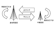
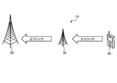
- FIG. 1 is a diagram showing an outline of in-band full-duplex communication.
- conventional full duplex communication is performed using different frequencies in the transmission band and the reception band in order to avoid interference between the transmission signal and the reception signal.
- in-band full-duplex communication transmission and reception are performed simultaneously using the same band.
- a signal transmitted by the communication device leaks into the receiving circuit of the communication device, so that very strong self-interference occurs.
- advances in interference canceling technology make it possible to reduce the self-interference. It is expected that the frequency utilization efficiency can be doubled at the maximum as compared with the conventional full-duplex communication due to the progress of the interference canceling technology.
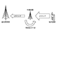
- FIG. 2 is a diagram showing an example of a backhaul link and an access link for in-band full-duplex communication.
- the relay device relay station
- the relay device is equipped with a self-interference canceller
- full-band communication within the band between the backhaul link and the access link is assumed.
- the relay device can improve frequency utilization efficiency and reduce packet transmission delay due to passing through the relay device.
- the in-band full-duplex communication between the backhaul link and the access link is given as an example, but it can also be applied to the in-band full-duplex communication between the backhaul link and the backhaul link. A degree of effect can be expected.
- the relay device of the present embodiment is a device that transmits information from one communication device to the other communication device.
- the relay device is a device that receives a signal from one communication device and transmits the signal to the other communication device.
- the communication performed by the relay device is wireless communication between one communication device and the relay device and between the relay device and the other communication device.
- Residual self-interference> 3 and 4 are diagrams illustrating residual self-interference that occurs in in-band full-duplex communication.
- the self-interference canceller is mounted on a communication device such as a relay device.
- self-interference residual self-interference
- self-interference that cannot be completely eliminated is the reception characteristic of a communication device that performs full-band communication within the band. Deteriorate. In particular, if the transmission power is large, the residual self-interference power that wraps around is also proportionally large, which makes reception using the same resources as transmission difficult.
- the communication device of the present embodiment (for example, a relay device that performs in-band full-duplex communication) is a radio resource for in-band full-duplex communication (hereinafter, while considering the influence of received power and residual self-interference power). , Also called Full Duplex Resource) to control the transmission power of the transmitted signal.
- a radio resource for in-band full-duplex communication hereinafter, while considering the influence of received power and residual self-interference power.
- Full Duplex Resource also called Full Duplex Resource
- a communication device for example, a relay device or a base station device
- a base station device including a relay device
- a base station device including a relay device
- the communication device estimates in advance the estimated reception power of the uplink access link transmitted from the terminal device and the residual self-interference generated by data transmission using the uplink backhaul link (uplink in the backhaul link). , Predict the estimated reception quality (CQI: Channel Quality Indicator).
- CQI Channel Quality Indicator
- the communication device controls another communication device (for example, a terminal device) on the data transmission side so as to increase the transmission power of data transmission using the uplink access link based on the estimated reception quality.
- the control source communication device for example, a relay device or a base station device
- FIG. 5 is a diagram showing communication control in consideration of residual self-interference.
- the communication device can realize high-quality in-band full-duplex communication. As a result, the communication device can achieve high communication performance.
- in-band full-duplex communication may be simply referred to as “full-duplex communication”.
- the communication system 1 includes a base station device and can be wirelessly connected to a terminal device.
- the communication system 1 may be compatible with radio access technology (RAT: Radio Access Technology) such as LTE (Long Term Evolution) and NR (New Radio).
- RAT Radio Access Technology
- LTE and NR are a kind of cellular communication technology, and enable mobile communication of a terminal device by arranging a plurality of areas covered by a base station in a cell shape.
- LTE shall include LTE-A (LTE-Advanced), LTE-A Pro (LTE-Advanced Pro), and EUTRA (Evolved Universal Terrestrial Radio Access).
- NR shall include NLAT (New Radio Access Technology) and FEUTRA (Further EUTRA).
- a single base station may manage a plurality of cells.
- the cell corresponding to LTE is referred to as an LTE cell
- the cell corresponding to NR is referred to as an NR cell.
- NR is the next generation (5th generation) wireless access technology (RAT) of LTE (4th generation communication including LTE-Advanced and LTE-Advanced Pro).
- RAT wireless access technology
- LTE 4th generation communication including LTE-Advanced and LTE-Advanced Pro
- NR is a wireless access technology that can support various use cases including eMBB (Enhanced Mobile Broadband), mMTC (Massive Machine Type Communications) and URLLC (Ultra-Reliable and Low Latency Communications).
- eMBB Enhanced Mobile Broadband
- mMTC Massive Machine Type Communications
- URLLC Ultra-Reliable and Low Latency Communications
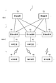
- FIG. 6 is a diagram showing a configuration example of the communication system 1 according to the embodiment of the present disclosure.
- Communication system 1 is a wireless communication system that provides a wireless access network to a terminal device.
- communication system 1 is a cellular communication system using wireless access technology such as LTE and NR.
- the radio access network may be E-UTRAN (Evolved Universal Terrestrial Radio Access Network) or NG-RAN (Next Generation Radio Access Network).
- the communication system 1 includes a management device 10, a base station device 20, a relay device 30, and a terminal device 40.
- the communication system 1 provides a user with a wireless network capable of mobile communication by operating the wireless communication devices constituting the communication system 1 in cooperation with each other.
- the radio network of this embodiment is composed of a radio access network RAN and a core network CN.
- the wireless communication device is a device having a wireless communication function, and in the example of FIG. 6, the base station device 20, the relay device 30, and the terminal device 40 correspond to each other.
- the communication system 1 may include a plurality of management devices 10, a base station device 20, a relay device 30, and a terminal device 40, respectively.
- the communication system 1 includes management devices 10 1 , 10 2 and the like as the management device 10.
- the communication system 1 includes base station apparatus 20 1 as a base station apparatus 20 has a 20 2, 20 3, etc., and a relay apparatus 30 1, 30 2, etc. as the relay device 30.
- the communication system 1 includes a terminal device 40 1, 40 2, 40 3, etc. as a terminal device 40.
- the device in the figure may be considered as a device in a logical sense. That is, a part of the devices in the figure may be realized by a virtual machine (VM: Virtual Machine), a container (Container), a docker (Docker), etc., and they may be mounted on physically the same hardware.
- VM Virtual Machine
- Container Container
- Docker docker
- LTE base stations may be referred to as eNodeB (Evolved Node B) or eNB.
- the NR base station may be referred to as NGRAN Node (Next Generation RAN node), gNodeB or gNB.
- a terminal device also referred to as a mobile station, mobile station device, or terminal
- the terminal device is a kind of communication device, and is also referred to as a mobile station, a mobile station device, or a terminal.
- the concept of a communication device includes not only a portable mobile device (terminal device) such as a mobile terminal, but also a device installed on a structure or a mobile body.
- the structure or the moving body itself may be regarded as a communication device.
- the concept of a communication device includes not only a terminal device but also a base station device and a relay device.
- a communication device is a type of processing device and information processing device. Further, the communication device can be paraphrased as a transmission device or a reception device.
- the management device 10 is a device that manages a wireless network.
- the management device 10 is a device that manages the communication of the base station device 20.
- the management device 10 is a device that functions as an MME (Mobility Management Entity), an AMF (Access and Mobility Management Function), or an SMF (Session Management Function).
- MME Mobility Management Entity
- AMF Access and Mobility Management Function
- SMF Session Management Function
- the management device 10 constitutes a core network CN together with a gateway device and the like.
- the core network CN is, for example, a network owned by a predetermined entity (subject) such as a mobile communication operator.
- the core network CN is EPC (Evolved Packet Core) or 5GC (5G Core network).
- the predetermined entity may be the same as the entity that uses, operates, and / or manages the base station apparatus 20, or may be different.
- the management device 10 may have a gateway function.
- the management device 10 may have a function as an S-GW or a P-GW.
- the management device 10 may have a function as an UPF (User Plane Function).
- the management device 10 may be SMF, PCF, UDM, or the like.
- the core network CN may include SMF, PCF, UDM and the like.
- the management device 10 does not necessarily have to be a device that constitutes the core network CN.
- the core network CN is a core network of W-CDMA (Wideband Code Division Multiple Access) or cdma2000 (Code Division Multiple Access 2000).
- the management device 10 may be a device that functions as an RNC (Radio Network Controller).
- the management device 10 is connected to each of the plurality of base station devices 20.
- each of the plurality of base station devices 20 For example, in the case of 5GS, there is an N2 reference point between the AMF and the NG-RAN, and the AMF and the NG-RAN are logically connected to each other via the NG interface.
- the management device 10 manages the position of the terminal device 40 for each terminal device 40 in an area unit (for example, Tracking Area, RAN Notification Area) composed of a plurality of cells.
- the management device 10 determines which base station device (or which cell) the terminal device 40 is connected to, which base station device (or which cell) is in the communication area, and the like. It may be grasped and managed for each.
- the cell provided by the base station apparatus 20 is called a serving cell.
- the serving cell may include pCell (Primary Cell) and sCell (Secondary Cell).
- pCell Primary Cell
- sCell Secondary Cell
- MN Master Node
- dual connectivity include EUTRA-EUTRA Dual Connectivity, EUTRA-NR Dual Connectivity (ENDC), EUTRA-NR Dual Connectivity with 5GC, NR-EUTRA Dual Connectivity (NEDC), and NR-NR Dual Connectivity.
- the serving cell may include a PSCell (Primary Secondary Cell or Primary SCG Cell). That is, when dual connectivity is provided to the UE, the PSCell and sCell (s) provided by the SN (Secondary Node) are called SCG (Secondary Cell Group).
- PSCell Primary Secondary Cell or Primary SCG Cell
- SCG Secondary Cell Group
- One downlink component carrier (Downlink Component Carrier) and one uplink component carrier (Uplink Component Carrier) may be associated with one cell.
- the system bandwidth corresponding to one cell may be divided into a plurality of bandwidth parts (BWP: Bandwidth Part).
- BWP Bandwidth Part
- one or a plurality of BWPs may be set in the UE, and one BWP may be used in the UE as an active BWP (Active BWP).
- the radio resources for example, frequency band, numerology (subcarrier spacing), slot format (Slot configuration)
- one base station apparatus may provide a plurality of cells.
- the base station device 20 is a wireless communication device that wirelessly communicates with the terminal device 40.
- the base station device 20 is a type of communication device. Further, the base station device 20 is a kind of information processing device.
- the base station device 20 may be, for example, a device corresponding to a wireless base station (Base Station, Node B, eNB, gNB, etc.) or a wireless access point (Access Point).
- a wireless base station Base Station, Node B, eNB, gNB, etc.
- the base station device 20 may be referred to as 3GPP access (3GPP Access).
- 3GPP Access 3GPP Access
- non-3GPP access Non-3GPP Access
- the base station device 20 may be a wireless relay station (Relay Node).
- the base station device 20 may be an optical overhanging device called RRH (Remote Radio Head).
- the base station device 20 may be a receiving station device such as an FPU (Field Pickup Unit). Further, the base station apparatus 20 is an IAB (Integrated Access and Backhaul) donor node or an IAB relay node that provides a wireless access line and a wireless backhaul line by time division multiplexing, frequency division multiplexing, or spatial division multiplexing. You may.
- IAB Integrated Access and Backhaul
- IAB relay node that provides a wireless access line and a wireless backhaul line by time division multiplexing, frequency division multiplexing, or spatial division multiplexing. You may.
- the base station device 20 When the base station device 20 is gNB, the base station device may be referred to as a combination of gNB CU (Central Unit) and gNB DU (Distributed Unit), or any of these.
- the base station of the wireless communication system may be referred to as a base station device.
- the base station device 20 may be configured to be capable of wireless communication with another base station device 20.
- the devices when a plurality of base station devices 20 are eNBs or a combination of eNBs and gNBs, the devices may be connected by an X2 interface. Further, when a plurality of base station devices 20 are gNBs or a combination of eNBs and gNBs, the devices may be connected by an Xn interface.
- a plurality of base station devices 20 are a combination of gNB CU and gNB DU, the devices may be connected by an F1 interface.
- the message information (RRC signaling or DCI information) described later may be communicated between the plurality of base station devices 20 (for example, via the X2, Xn, and F1 interfaces).
- the wireless access technology used by the base station device 20 may be a cellular communication technology or a wireless LAN technology. Of course, the wireless access technology used by the base station apparatus 20 is not limited to these, and may be another wireless access technology.
- the wireless access technology used by the base station device 20 may be LPWA (Low Power Wide Area) communication technology.
- LPWA communication is communication conforming to the LPWA standard. Examples of LPWA standards include ELTRES, ZETA, SIGFOX, LoRaWAN, NB-IoT and the like. Of course, the LPWA standard is not limited to these, and may be another LPWA standard.
- the wireless communication used by the base station apparatus 20 may be wireless communication using millimeter waves. Further, the wireless communication used by the base station device 20 may be wireless communication using radio waves, or wireless communication (optical wireless) using infrared rays or visible light.
- the base station device 20 may be capable of NOMA (Non-Orthogonal Multiple Access) communication with the terminal device 40.
- NOMA communication refers to communication (transmission, reception, or both) using non-orthogonal resources.
- the base station device 20 may be configured to enable NOMA communication with another base station device 20 and a relay device 30.
- the base station device 20 may be able to communicate with each other via an interface between the base station device and the core network (for example, S1 Interface, etc.). This interface may be wired or wireless. Further, the base station devices may be able to communicate with each other via an interface between the base station devices (for example, X2 Interface, S1 Interface, etc.). This interface may be wired or wireless.
- the plurality of base station devices 20 may be able to communicate with each other via a base station device-core network interface (for example, NG Interface, S1 Interface, etc.). This interface may be wired or wireless. Further, the base station devices may be able to communicate with each other via an interface between the base station devices (for example, Xn Interface, X2 Interface, etc.). This interface may be wired or wireless.
- a base station device-core network interface for example, NG Interface, S1 Interface, etc.
- This interface may be wired or wireless.
- the base station devices may be able to communicate with each other via an interface between the base station devices (for example, Xn Interface, X2 Interface, etc.). This interface may be wired or wireless.
- the base station device 20 can be used, operated, and / or managed by various entities.
- the entities include a mobile network operator (MNO: Mobile Network Operator), a virtual mobile network operator (MVNO: Mobile Virtual Network Operator), a virtual mobile communication enabler (MVNE: Mobile Virtual Network Enabler), and a neutral host.
- MNO Mobile Network Operator
- MVNO Mobile Virtual Network Operator
- MVNE Virtual Mobile Network Enabler
- NTN Neutral Host Network
- operators enterprises, educational institutions (school corporations, local government education committees, etc.), real estate (buildings, condominiums, etc.) managers, individuals, etc. can be assumed.
- the base station apparatus 20 may be installed and / or operated by one business operator, or may be installed and / or operated by one individual.
- the installation / operation entity of the base station device 20 is not limited to these.
- the base station device 20 may be jointly installed and operated by a plurality of businesses or a plurality of individuals.
- the base station device 20 may be a shared facility used by a plurality of businesses or a plurality of individuals. In this case, the installation and / or operation of the equipment may be carried out by a third party different from the user.
- a base station device also referred to as a base station
- a base station includes not only a donor base station but also a relay base station (also referred to as a relay station, a relay station, a relay base station, or a relay station device).
- a base station includes not only a structure having a function of a base station but also a device installed in the structure.
- Structures are, for example, high-rise buildings, houses, steel towers, station facilities, airport facilities, port facilities, stadiums, and other buildings.
- the concept of structure includes not only buildings but also non-building structures such as tunnels, bridges, dams, fences, and iron pillars, and equipment such as cranes, gates, and wind turbines.
- the concept of a structure includes not only structures on land (above ground in a narrow sense) or underground, but also structures on water such as piers and mega floats, and structures underwater such as marine observation facilities.
- the base station device can be rephrased as a processing device or an information processing device.
- the base station device 20 may be a donor station or a relay station (relay station). Further, the base station device 20 may be a fixed station or a mobile station.
- a mobile station is a wireless communication device (for example, a base station device) configured to be mobile.
- the base station device 20 may be a device installed on the mobile body or may be the mobile body itself.
- a relay station device having mobility can be regarded as a base station device 20 as a mobile station.
- devices such as vehicles, drones (Aerial Vehicles), and smartphones that are originally mobile and equipped with the functions of base station devices (at least some of the functions of base station devices) are also bases as mobile stations. Corresponds to the station device 20.
- the mobile body may be a mobile terminal such as a smartphone or a mobile phone.
- the moving body may be a moving body (for example, a vehicle such as a car, a bicycle, a bus, a truck, a motorcycle, a train, a linear motor car, etc.) that moves on land (ground in a narrow sense), or in the ground (for example, a vehicle).
- a moving body for example, a subway moving in a tunnel.
- the moving body may be a moving body moving on water (for example, a ship such as a passenger ship, a cargo ship, or a hovercraft), or a moving body moving underwater (for example, a submersible, a submarine, an unmanned submarine, etc.). Submersible).
- the moving body may be a moving body moving in the atmosphere (for example, an aircraft such as an airplane, an airship, or a drone (Aerial Vehicle)), or a moving body moving outside the atmosphere (for example, an artificial satellite, space). It may be an artificial celestial body such as a ship, a space station, or a spacecraft).
- a moving body that moves outside the atmosphere can be rephrased as a space moving body.
- the base station device 20 may be a ground base station device (ground station device) installed on the ground.
- the base station device 20 may be a base station device arranged on a structure on the ground, or may be a base station device installed on a mobile body moving on the ground.
- the base station device 20 may be an antenna installed in a structure such as a building and a signal processing device connected to the antenna.
- the base station device 20 may be a structure or a moving body itself. "Ground" is not only on land (ground in a narrow sense) but also on the ground in a broad sense including underground, water, and water.
- the base station device 20 is not limited to the ground base station device.
- the base station device 20 may be a non-ground base station device (non-ground station device) capable of floating in the air or space.
- the base station device 20 may be an aircraft station device or a satellite station device.
- the aircraft station device is a wireless communication device that can float in the atmosphere (including the stratosphere) such as aircraft.
- the aircraft station device may be a device mounted on an aircraft or the like, or may be an aircraft itself.
- the concept of an aircraft includes not only heavy aircraft such as airplanes and gliders, but also light aircraft such as balloons and airships.
- the concept of an aircraft includes not only heavy aircraft and light aircraft, but also rotary-wing aircraft such as helicopters and autogyros.
- the aircraft station device (or the aircraft on which the aircraft station device is mounted) may be an unmanned aerial vehicle such as a drone.
- unmanned aerial vehicle also includes unmanned aerial vehicles (UAS: Unmanned Aircraft Systems) and tethered unmanned aerial vehicles (tethered UAS).
- UAS Unmanned Aircraft Systems
- tethered UAS tethered unmanned aerial vehicles
- unmanned aerial vehicle includes a light unmanned aerial vehicle system (LTA: Lighter than Air UAS) and a heavy unmanned aerial vehicle system (HTA: Heavier than Air UAS).
- HAPs High Altitude UAS Platforms.
- the satellite station device is a wireless communication device that can float outside the atmosphere.
- the satellite station device may be a device mounted on a space mobile body such as an artificial satellite, or may be a space mobile body itself.
- the satellites that serve as satellite station equipment are low orbit (LEO: Low Earth Orbiting) satellites, medium orbit (MEO: Medium Earth Orbiting) satellites, geostationary (GEO: Geostationary Earth Orbiting) satellites, and high elliptical orbit (HEO: Highly Elliptical Orbiting). It may be any satellite.
- the satellite station device may be a device mounted on a low earth orbit satellite, a medium earth orbit satellite, a geostationary satellite, or a high elliptical orbit satellite.
- the size of the coverage of the base station apparatus 20 may be as large as a macro cell or as small as a pico cell. Of course, the size of the coverage of the base station apparatus 20 may be extremely small, such as a femtocell. Further, the base station apparatus 20 may have a beamforming capability. In this case, the base station apparatus 20 may form a cell or a service area for each beam.
- the base station apparatus 20 1 is connected to the relay device 30 1, the base station apparatus 20 2 is connected to the relay device 30 2.
- the base station apparatus 20 1 is able to indirectly communicate wirelessly with the terminal device 40 via the relay device 30 1.
- the base station apparatus 20 2 it is possible to indirectly communicate wirelessly with the terminal device 40 via the relay device 30 2.
- the relay device 30 is a device that serves as a relay station for the base station.
- the relay device 30 is a type of base station device. Further, the relay device 30 is a kind of information processing device.
- the relay device can be rephrased as a relay base station device (or a relay base station).
- the relay device 30 can perform wireless communication such as NOMA communication with the terminal device 40.
- the relay device 30 relays the communication between the base station device 20 and the terminal device 40.
- the relay device 30 may be configured to enable wireless communication with another relay device 30 and the base station device 20.
- the relay device 30 may be a ground station device or a non-ground station device.
- the relay device 30 and the base station device 20 form a radio access network RAN.
- the relay device of the present embodiment may be a fixed device, a movable device, or a floating device. Further, the size of the coverage of the relay device of the present embodiment is not limited to a specific size. For example, the cell covered by the relay device may be a macro cell, a micro cell, or a small cell.
- the relay device of the present embodiment is not limited to the device to be mounted as long as the relay function is satisfied.
- the repeater may be mounted on a terminal device such as a smartphone, a car or a rickshaw, a balloon, an airplane, a drone, a television, a game machine, or an air conditioner. , Refrigerators, lighting fixtures and other home appliances.
- the configuration of the relay device 30 may be the same as the configuration of the base station device 20 described above.
- the relay device 30 may be a device installed on the mobile body or may be the mobile body itself, similarly to the base station device 20 described above.
- the mobile body may be a mobile terminal such as a smartphone or a mobile phone.
- the moving body may be a moving body that moves on land (ground in a narrow sense) or may be a moving body that moves in the ground.
- the moving body may be a moving body moving on the water or a moving body moving in the water.
- the moving body may be a moving body moving in the atmosphere or a moving body moving out of the atmosphere.
- the base station device 20 may be a ground station device or a non-ground station device.
- the relay device 30 may be an aircraft station device or a satellite station device.
- the size of the coverage of the relay device 30 may be as large as a macro cell or as small as a pico cell, as in the base station device 20. Of course, the size of the coverage of the relay device 30 may be extremely small, such as a femtocell. Further, the relay device 30 may have a beamforming ability. In this case, the relay device 30 may form a cell or a service area for each beam.
- the configuration of the relay device 30 may be the same as the configuration of the base station device 20 described above.
- the terminal device 40 is a wireless communication device that wirelessly communicates with the base station device 20 or the relay device 30.
- the terminal device 40 is, for example, a mobile phone, a smart device (smartphone or tablet), a PDA (Personal Digital Assistant), or a personal computer.
- the terminal device 40 may be a device such as a commercial camera provided with a communication function, or may be a motorcycle, a mobile relay vehicle, or the like equipped with a communication device such as an FPU (Field Pickup Unit). ..
- the terminal device 40 may be an M2M (Machine to Machine) device or an IoT (Internet of Things) device.
- the terminal device 40 may be described by, for example, MTC UE, NB-IoT UE, Cat. Sometimes referred to as MUE.
- the terminal device 40 may be capable of side link communication with another terminal device 40.
- the terminal device 40 may be able to use an automatic retransmission technique such as HARQ when performing side link communication.
- the terminal device 40 may be capable of NOMA communication with the base station device 20 and the relay device 30.
- the terminal device 40 may also be capable of NOMA communication in communication (side link) with another terminal device 40.
- the terminal device 40 may be capable of LPWA communication with other communication devices (for example, the base station device 20, the relay device 30, and the other terminal device 40).
- the wireless communication used by the terminal device 40 may be wireless communication using millimeter waves.
- the wireless communication (including side link communication) used by the terminal device 40 may be wireless communication using radio waves or wireless communication using infrared rays or visible light (optical wireless). Good.
- the terminal device 40 may be a mobile device.
- the mobile device is a mobile wireless communication device.
- the terminal device 40 may be a wireless communication device installed on the mobile body or may be the mobile body itself.
- the terminal device 40 may be a vehicle (Vehicle) moving on the road such as an automobile, a bus, a truck, or a motorcycle, or a wireless communication device mounted on the vehicle.
- the moving body may be a mobile terminal, or may be a moving body that moves on land (ground in a narrow sense), in the ground, on the water, or in the water.
- the moving body may be a moving body such as a drone (Aerial UE) or a helicopter that moves in the atmosphere, or a moving body that moves outside the atmosphere such as an artificial satellite.
- the terminal device 40 may be connected to a plurality of base station devices or a plurality of cells at the same time to perform communication. For example, when one base station apparatus can provide a plurality of cells, the terminal apparatus 40 can perform carrier aggregation by using one cell as a pCell and another cell as an sCell. Further, when the plurality of base station devices 20 can each provide one or a plurality of cells, the terminal device 40 pCells one or a plurality of cells managed by one of the base station devices (MN (for example, MeNB or MgNB)).
- MN for example, MeNB or MgNB
- DC Dual Connectivity
- MC Multi Connectivity
- CA Carrier Aggregation
- DC Dual Connectivity
- MC Multi-Connectivity
- CoMP coordinated multi-point transmission and reception
- the terminal device 40 does not necessarily have to be a device directly used by a person.
- the terminal device 40 may be a sensor installed in a machine or the like in a factory, such as a so-called MTC (Machine Type Communication).
- the terminal device 40 may be an M2M (Machine to Machine) device or an IoT (Internet of Things) device.
- the terminal device 40 may be a device having a relay communication function as represented by D2D (Device to Device) and V2X (Vehicle to everything).
- the terminal device 40 may be a device called CPE (Client Premises Equipment) used in a wireless backhaul or the like.
- CPE Customer Premises Equipment
- each device constituting the communication system 1 will be specifically described.
- the configuration of each device shown below is just an example.
- the configuration of each device may differ from the configuration below.
- FIG. 7 is a diagram showing a configuration example of the management device 10 according to the embodiment of the present disclosure.
- the management device 10 is a device that manages a wireless network.
- the management device 10 includes a communication unit 11, a storage unit 12, and a control unit 13.
- the configuration shown in FIG. 7 is a functional configuration, and the hardware configuration may be different from this. Further, the functions of the management device 10 may be distributed and implemented in a plurality of physically separated configurations.
- the management device 10 may be composed of a plurality of server devices.
- the communication unit 11 is a communication interface for communicating with other devices.
- the communication unit 11 may be a network interface or a device connection interface.
- the communication unit 11 may be a LAN (Local Area Network) interface such as a NIC (Network Interface Card), or a USB interface composed of a USB (Universal Serial Bus) host controller, a USB port, or the like. May be good.
- the communication unit 11 may be a wired interface or a wireless interface.
- the communication unit 11 functions as a communication means of the management device 10.
- the communication unit 11 communicates with the base station device 20 under the control of the control unit 13.
- the storage unit 12 is a data readable / writable storage device such as a DRAM (Dynamic Random Access Memory), a SRAM (Static Random Access Memory), a flash memory, and a hard disk.
- the storage unit 12 functions as a storage means for the management device 10.
- the storage unit 12 stores, for example, the connection state of the terminal device 40.
- the storage unit 12 stores the RRC (Radio Resource Control) state and the ECM (EPS Connection Management) state of the terminal device 40.
- the storage unit 12 may function as a home memory for storing the position information of the terminal device 40.
- the control unit 13 is a controller that controls each unit of the management device 10.
- the control unit 13 is realized by, for example, a processor such as a CPU (Central Processing Unit) or an MPU (Micro Processing Unit).
- the control unit 13 is realized by the processor executing various programs stored in the storage device inside the management device 10 using a RAM (Random Access Memory) or the like as a work area.
- the control unit 13 may be realized by an integrated circuit such as an ASIC (Application Specific Integrated Circuit) or an FPGA (Field Programmable Gate Array).
- the CPU, MPU, ASIC, and FPGA can all be regarded as controllers.
- FIG. 8 is a diagram showing a configuration example of the base station device 20 according to the embodiment of the present disclosure.
- the base station apparatus 20 can simultaneously perform data transmission and data reception using the same band.
- the base station device 20 can perform in-band full-duplex communication with other wireless communication devices such as the terminal device 40 and the relay device 30.
- the base station device 20 may be capable of NOMA communication with another wireless communication device.
- the base station device 20 includes a communication unit 21, a storage unit 22, an upper layer processing unit 23, and a control unit 24.
- the configuration shown in FIG. 8 is a functional configuration, and the hardware configuration may be different from this. Further, the functions of the base station apparatus 20 may be distributed and implemented in a plurality of physically separated configurations.
- the communication unit 21 is a signal processing unit for wireless communication with other wireless communication devices (for example, a terminal device 40, a relay device 30, and another base station device 20).
- the communication unit 21 can simultaneously perform data transmission and data reception using the same band.
- the base station device 20 can perform in-band full-duplex communication with other communication devices such as the terminal device 40 and the relay device 30.
- the communication unit 21 operates according to the control of the control unit 24.
- the communication unit 21 corresponds to one or more wireless access methods.
- the communication unit 21 corresponds to both NR and LTE.
- the communication unit 21 may support W-CDMA and cdma2000 in addition to NR and LTE. Further, the communication unit 21 may support communication using NOMA.
- the communication unit 21 includes a reception processing unit 211, a transmission processing unit 212, a self-canceller unit 213, and an antenna 214.
- the communication unit 21 may include a plurality of reception processing units 211, transmission processing units 212, and antennas 214, respectively.
- each unit of the communication unit 21 may be individually configured for each wireless access method.
- the reception processing unit 211 and the transmission processing unit 212 may be individually configured by LTE and NR.
- the reception processing unit 211 processes the uplink signal received via the antenna 214.
- the reception processing unit 211 includes a wireless reception unit 211a, a multiple separation unit 211b, a demodulation unit 211c, and a decoding unit 211d.
- the wireless receiver 211a performs down-conversion, removal of unnecessary frequency components, control of amplification level, orthogonal demodulation, conversion to digital signal, removal of guard interval (cyclic prefix), and fast Fourier transform for the uplink signal.
- the frequency domain signal is extracted by.
- the multiplex separation unit 211b separates uplink channels such as PUSCH (Physical Uplink Shared Channel) and PUCCH (Physical Uplink Control Channel) and uplink reference signals from the signal output from the wireless reception unit 211a.
- the demodulation unit 211c demodulates the received signal with respect to the modulation symbol of the uplink channel by using a modulation method such as BPSK (Binary Phase Shift Keying) or QPSK (Quadrature Phase Shift Keying).
- BPSK Binary Phase Shift Keying
- QPSK Quadrature Phase Shift Keying
- the modulation method used by the demodulation unit 211c may be 16QAM (Quadrature Amplitude Modulation), 64QAM, or 256QAM. In this case, the signal points on the constellation do not necessarily have to be equidistant.
- the constellation may be a non-uniform constellation (NUC: Non Uniform Constellation).
- the decoding unit 211d performs decoding processing on the coded bits of the demodulated uplink channel. The decoded uplink data and uplink control information are output to the control unit 24.
- the transmission processing unit 212 performs the transmission processing of the downlink control information and the downlink data.
- the transmission processing unit 212 includes a coding unit 212a, a modulation unit 212b, a multiplexing unit 212c, and a wireless transmission unit 212d.
- the coding unit 212a encodes the downlink control information and the downlink data input from the control unit 24 by using a coding method such as block coding, convolutional coding, or turbo coding.
- the coding unit 212a may be encoded by a polar code (Polar code) or by an LDPC code (Low Density Parity Check Code).
- the modulation unit 212b modulates the coding bits output from the coding unit 212a by a predetermined modulation method such as BPSK, QPSK, 16QAM, 64QAM, 256QAM and the like. In this case, the signal points on the constellation do not necessarily have to be equidistant.
- the constellation may be a non-uniform constellation.
- the multiplexing unit 212c multiplexes the modulation symbol of each channel and the downlink reference signal and arranges them in a predetermined resource element.
- the wireless transmission unit 212d performs various signal processing on the signal from the multiplexing unit 212c.
- the radio transmitter 212d converts to the time domain by fast Fourier transform, adds a guard interval (cyclic prefix), generates a baseband digital signal, converts to an analog signal, quadrature modulation, up-converts, and extra. Performs processing such as removing frequency components and amplifying power.
- the signal generated by the transmission processing unit 212 is transmitted from the antenna 214.
- the self-canceller unit 213 cancels the self-interference given to the data reception of the base station device 20 itself due to the data transmission of the base station device 20 itself. For example, the self-canceller unit 213 cancels self-interference when the communication unit 21 performs in-band full-duplex communication. For example, the self-canceller unit 213 removes the influence of the transmission signal from the reception signal acquired by the reception processing unit 211 based on the transmission signal generated by the transmission processing unit 212.
- the storage unit 22 is a storage device that can read and write data such as DRAM, SRAM, flash memory, and hard disk.
- the storage unit 22 functions as a storage means for the base station device 20.
- the upper layer processing unit 23 is a communication interface for communicating with a node (for example, the management device 10) located higher on the network.
- the upper layer processing unit 23 is a LAN interface such as a NIC.
- the upper layer processing unit 23 may be a wired interface or a wireless interface.
- the upper layer processing unit 23 functions as a network communication means of the base station apparatus 20.
- the control unit 24 is a controller that controls each unit of the base station device 20.
- the control unit 24 is realized by, for example, a processor (hardware processor) such as a CPU (Central Processing Unit) or an MPU (Micro Processing Unit).
- the control unit 24 is realized by the processor executing various programs stored in the storage device inside the base station device 20 using a RAM (Random Access Memory) or the like as a work area.
- the control unit 24 may be realized by an integrated circuit such as an ASIC (Application Specific Integrated Circuit) or an FPGA (Field Programmable Gate Array).
- the CPU, MPU, ASIC, and FPGA can all be regarded as controllers.
- the control unit 24 includes an acquisition unit 241, a communication control unit 242, a generation unit 243, a reception unit 244, and a transmission unit 245.
- Each block (acquisition unit 241 to transmission unit 245) constituting the control unit 24 is a functional block indicating the function of the control unit 24, respectively.
- These functional blocks may be software blocks or hardware blocks.
- each of the above-mentioned functional blocks may be one software module realized by software (including a microprocessor), or may be one circuit block on a semiconductor chip (die).
- each functional block may be one processor or one integrated circuit. The method of configuring the functional block is arbitrary.
- the control unit 24 may be configured in a functional unit different from the above-mentioned functional block.
- the operation of each block (acquisition unit 241 to transmission unit 245) constituting the control unit 24 may be the same as the operation of each block constituting the control unit of the relay device 30.
- the configuration of the relay device 30 will be described later.
- FIG. 9 is a diagram showing a configuration example of the relay device 30 according to the embodiment of the present disclosure.
- the relay device 30 can simultaneously perform data transmission and data reception using the same band.
- the relay device 30 can perform in-band full-duplex communication with other wireless communication devices such as the terminal device 40 and the relay device 30.
- the relay device 30 may be capable of NOMA communication with another wireless communication device.
- the relay device 30 includes a communication unit 31, a storage unit 32, an upper layer processing unit 33, and a control unit 34.
- the configuration shown in FIG. 9 is a functional configuration, and the hardware configuration may be different from this. Further, the functions of the relay device 30 may be distributed and implemented in a plurality of physically separated configurations.
- the communication unit 31 is a signal processing unit for wireless communication with other wireless communication devices (for example, base station device 20, terminal device 40, and other relay device 30).
- the communication unit 31 can simultaneously perform data transmission and data reception using the same band.
- the communication unit 31 can perform in-band full-duplex communication with other communication devices such as the base station device 20 and the terminal device 40.
- the communication unit 31 operates according to the control of the control unit 34.
- the communication unit 31 corresponds to one or more wireless access methods.
- the communication unit 41 corresponds to both NR and LTE.
- the communication unit 31 may support W-CDMA and cdma2000 in addition to NR and LTE. Further, the communication unit 31 may support communication using NOMA.
- the communication unit 31 includes a reception processing unit 311, a transmission processing unit 312, a self-canceller unit 313, and an antenna 314.
- the communication unit 31 may include a plurality of reception processing units 311, transmission processing units 312, self-canceller units 313, and antennas 314, respectively.
- the communication unit 31, the reception processing unit 311, the transmission processing unit 312, the self-canceller unit 313, and the antenna 314 are configured by the communication unit 21, the reception processing unit 211, the transmission processing unit 212, and the self-canceller unit 213 of the base station apparatus 20. And antenna 214.
- the storage unit 32 is a storage device that can read and write data such as DRAM, SRAM, flash memory, and hard disk.
- the storage unit 32 functions as a storage means for the relay device 30.
- the configuration of the storage unit 32 is the same as that of the storage unit 22 of the base station device 20.
- the upper layer processing unit 33 is a communication interface for communicating with a node located higher on the network.
- the upper layer processing unit 33 is a LAN interface such as a NIC.
- the upper layer processing unit 33 may be a wired interface or a wireless interface.
- the upper layer processing unit 33 functions as a network communication means of the relay device 30.
- the upper layer processing unit 33 communicates with the base station device 20 under the control of the control unit 34.
- the control unit 34 is a controller that controls each unit of the relay device 30.
- the control unit 34 is realized by, for example, a processor (hardware processor) such as a CPU or MPU.
- the control unit 34 is realized by the processor executing various programs stored in the storage device inside the relay device 30 with the RAM or the like as a work area.
- the control unit 34 may be realized by an integrated circuit such as an ASIC or FPGA.
- the CPU, MPU, ASIC, and FPGA can all be regarded as controllers.
- the control unit 34 includes an acquisition unit 341, a communication control unit 342, a generation unit 343, a reception unit 344, and a transmission unit 345.
- Each block (acquisition unit 341 to transmission unit 345) constituting the control unit 34 is a functional block indicating the function of the control unit 34, respectively.
- These functional blocks may be software blocks or hardware blocks.
- each of the above-mentioned functional blocks may be one software module realized by software (including a microprocessor), or may be one circuit block on a semiconductor chip (die).
- each functional block may be one processor or one integrated circuit. The method of configuring the functional block is arbitrary.
- the control unit 34 may be configured in a functional unit different from the above-mentioned functional block.
- the operation of each block (acquisition unit 341 to transmission unit 345) constituting the control unit 34 is the same as the operation of each block (acquisition unit 241 to transmission unit 245) constituting the control unit 24 of the base station apparatus 20. There may be.
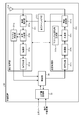
- FIG. 10 is a diagram showing a specific configuration example around the signal processing of the relay device 30.
- the relay device 30 shown in FIG. 10 includes a reception processing unit 311, a transmission processing unit 312, a self-canceller unit 313, an antenna 314, a storage unit 32, an upper layer processing unit 33, and a control unit 34. ..
- the reception processing unit 311 processes the uplink signal received via the antenna 314.
- the reception processing unit 311 includes a wireless reception unit 311a, a multiple separation unit 311b, a demodulation unit 311c, a decoding unit 311d, and a channel measurement unit 311e.
- the channel measurement unit 311e measures the state of the channel based on the processing result of the multiple separation unit 311b, and outputs the measurement result to the multiple separation unit 311b and the control unit 34.
- the functions of the wireless reception unit 311a, the multiple separation unit 311b, the demodulation unit 311c, and the decoding unit 311d are the same as the functions of the wireless reception unit 211a, the multiple separation unit 211b, the demodulation unit 211c, and the decoding unit 211d of the base station apparatus 20. is there.
- the transmission processing unit 312 performs downlink control information and downlink data transmission processing.
- the transmission processing unit 312 includes an encoding unit 312a, a modulation unit 312b, a multiplexing unit 312c, a wireless transmission unit 312d, and a downlink reference signal generation unit 312e.
- the downlink reference signal generation unit 312e generates a downlink reference signal to be transmitted to a lower node on the network.
- the configurations of the coding unit 312a, the modulation unit 312b, the multiplexing unit 312c, and the radio transmission unit 312d are the same as the functions of the coding unit 212a, the modulation unit 212b, the multiplexing unit 212c, and the radio transmission unit 212d of the base station apparatus 20. is there.
- the self-canceller unit 313 cancels the self-interference given to the data reception of the relay device 30 itself due to the data transmission of the relay device 30 itself. For example, the self-canceller unit 313 cancels the self-interference when the communication unit 31 performs in-band full-duplex communication. For example, the self-canceller unit 313 removes the influence of the transmission signal from the reception signal acquired by the radio reception unit 311a based on the transmission signal generated by the radio transmission unit 312d.
- FIG. 11 is a diagram showing a configuration example of the terminal device 40 according to the embodiment of the present disclosure.
- the terminal device 40 can simultaneously perform data transmission and data reception using the same band.
- the terminal device 40 can perform in-band full-duplex communication with other wireless communication devices such as the base station device 20 and the relay device 30.
- the terminal device 40 may be capable of NOMA communication with another wireless communication device.
- the terminal device 40 includes a communication unit 41, a storage unit 42, an upper layer processing unit 43, an input / output unit 44, and a control unit 45.
- the configuration shown in FIG. 11 is a functional configuration, and the hardware configuration may be different from this. Further, the functions of the terminal device 40 may be distributed and implemented in a plurality of physically separated configurations. In the configuration of the terminal device 40, the upper layer processing unit 43 and the input / output unit 44 do not have to be essential components.
- the communication unit 41 is a signal processing unit for wireless communication with other wireless communication devices (for example, a base station device 20, a relay device 30, and another terminal device 40).
- the communication unit 41 can simultaneously perform data transmission and data reception using the same band.
- the communication unit 31 can perform in-band full-duplex communication with other communication devices such as the base station device 20 and the terminal device 40.
- the communication unit 41 operates according to the control of the control unit 45.
- the communication unit 41 corresponds to one or more wireless access methods.
- the communication unit 41 corresponds to both NR and LTE.
- the communication unit 41 may support W-CDMA and cdma2000 in addition to NR and LTE. Further, the communication unit 41 may support communication using NOMA.
- the communication unit 41 includes a reception processing unit 411, a transmission processing unit 412, a self-canceller unit 413, and an antenna 414.
- the communication unit 41 may include a plurality of reception processing units 411, transmission processing units 412, self-canceller units 413, and antennas 414, respectively.
- the communication unit 41, the reception processing unit 411, the transmission processing unit 412, the self-canceller unit 413, and the antenna 414 are configured by the communication unit 21, the reception processing unit 211, the transmission processing unit 212, and the self-canceller unit 213 of the base station apparatus 20. And antenna 214.
- the storage unit 42 is a storage device that can read and write data such as DRAM, SRAM, flash memory, and hard disk.
- the storage unit 42 functions as a storage means for the terminal device 40.
- the storage unit 42 stores "information regarding transmission from the unconnected state (information for unconnected transmission)" acquired from the base station device 20. "Information regarding transmission from the unconnected state (information for unconnected transmission)" will be described in detail later.
- the upper layer processing unit 43 is a communication interface for communicating with a node located higher on the network.
- the upper layer processing unit 43 is a LAN interface such as a NIC.
- the upper layer processing unit 43 may be a wired interface or a wireless interface.
- the upper layer processing unit 43 functions as a network communication means of the terminal device 40.
- the upper layer processing unit 43 communicates with other devices according to the control of the control unit 45.
- the input / output unit 44 is a user interface for exchanging information with the user.
- the input / output unit 44 is an operation device for the user to perform various operations such as a keyboard, a mouse, operation keys, and a touch panel.
- the input / output unit 44 is a display device such as a liquid crystal display (Liquid Crystal Display) or an organic EL display (Organic Electroluminescence Display).
- the input / output unit 44 may be an audio device such as a speaker or a buzzer.
- the input / output unit 44 may be a lighting device such as an LED (Light Emitting Diode) lamp.
- the input / output unit 44 functions as an input / output means (input means, output means, operation means, or notification means) of the terminal device 40.
- the control unit 45 is a controller that controls each unit of the terminal device 40.
- the control unit 45 is realized by, for example, a processor (hardware processor) such as a CPU or MPU.
- the control unit 45 is realized by the processor executing various programs stored in the storage device inside the terminal device 40 using the RAM or the like as a work area.
- the control unit 45 may be realized by an integrated circuit such as an ASIC or FPGA.
- the CPU, MPU, ASIC, and FPGA can all be regarded as controllers.
- the configuration of the control unit 45 may be the same as the configuration of the control unit 34 of the relay device 30.
- FIG. 12 is a diagram showing a specific configuration example around the signal processing of the terminal device 40.
- the terminal device 40 shown in FIG. 12 includes a reception processing unit 411, a transmission processing unit 412, a self-canceller unit 413, an antenna 414, a storage unit 42, an upper layer processing unit 43, and a control unit 45. ..
- the reception processing unit 411 processes the downlink signal received via the antenna 414.
- the reception processing unit 411 includes a wireless reception unit 411a, a multiple separation unit 411b, a demodulation unit 411c, a decoding unit 411d, and a channel measurement unit 411e.
- the channel measurement unit 411e measures the state of the channel based on the processing result of the multiple separation unit 411b, and outputs the measurement result to the multiple separation unit 411b and the control unit 34.
- the functions of the wireless reception unit 411a, the multiple separation unit 411b, the demodulation unit 411c, and the decoding unit 411d are the same as the functions of the wireless reception unit 211a, the multiple separation unit 211b, the demodulation unit 211c, and the decoding unit 211d of the base station apparatus 20. is there.
- the transmission processing unit 412 performs the transmission processing of the uplink control information and the uplink data.
- the transmission processing unit 412 includes a coding unit 412a, a modulation unit 412b, a multiplexing unit 412c, a wireless transmission unit 412d, and an uplink reference signal generation unit 412e.
- the uplink reference signal generation unit 412e generates an uplink reference signal to be transmitted to an upper node on the network.
- the configurations of the coding unit 412a, the modulation unit 412b, the multiplexing unit 412c, and the radio transmission unit 412d are the same as the functions of the coding unit 212a, the modulation unit 212b, the multiplexing unit 212c, and the radio transmission unit 212d of the base station apparatus 20. is there.
- the self-canceller unit 413 cancels the self-interference given to the data reception of the terminal device 40 itself due to the data transmission of the terminal device 40 itself. For example, the self-canceller unit 413 cancels self-interference when the communication unit 41 performs in-band full-duplex communication. For example, the self-canceller unit 413 removes the influence of the transmission signal from the reception signal acquired by the radio reception unit 411a based on the transmission signal generated by the radio transmission unit 412d.
- FIG. 13 is a diagram showing a first communication system. Assumed system 1A performs in-band full-duplex communication using both the backhaul link and the access link. In the example of FIG. 13, the communication system 1A performs multiplexing of the uplink backhaul link (uplink in the backhaul link) and the uplink access link (uplink in the access link). In the example of FIG. 13, the relay device 30 uses the same band to transmit uplink backhaul link data (hereinafter referred to as uplink backhaul link transmission) and uplink access link data reception (referred to as uplink access link reception). And are done at the same time.
- uplink backhaul link transmission uplink backhaul link data
- uplink access link data reception uplink access link reception
- FIG. 14 is a diagram showing a second communication system. Assumed system 1B performs in-band full-duplex communication using both the backhaul link and the access link.
- the assumed system 2A performs multiplexing of the downlink backhaul link (downlink in the backhaul link) and the downlink access link (downlink in the access link).
- the relay device 30 uses the same band to receive downlink backhaul link data (hereinafter referred to as downlink backhaul link reception) and downlink access link data transmission (referred to as downlink access link reception). , Are done at the same time.
- FIG. 15 is a diagram showing a third communication system. Assumed system 1C performs in-band full-duplex communication using a backhaul link or an access link. In the example of FIG. 15, the communication system 1C performs multiplexing of the uplink backhaul link and the downlink backhaul link. In the example of FIG. 15, the relay device 30 simultaneously performs uplink backhaul link transmission and downlink backhaul link reception using the same band.
- the communication control shown below may be applied to the communication control of the communication system 1C shown in FIG. 15 described above.
- the descriptions of the uplink backhaul link and the uplink access link shown below are appropriately replaced with the uplink or the downlink.
- the resource state is not limited to the resource state in NR.
- resource state type In NR, the following three types of resource states can be set. In the embodiment of the present embodiment, resource states other than the following three types (for example, resource states that specify side links) may be defined. (1) UL (uplink) (2) DL (downlink) (3) Flexible
- UL uplink
- UL indicates that the resource is a resource capable of transmitting an uplink channel / signal in the terminal device 40. Further, when UL is set as the type of resource state, it indicates that the resource is a resource that may receive an uplink channel / signal in the base station apparatus 20.
- DL Downlink
- DL indicates that the resource is a resource that is expected to receive the downlink channel / signal in the terminal device 40. Further, when DL is set as the type of resource state, it indicates that the resource is a resource that may transmit a downlink channel / signal in the base station apparatus 20.
- the relay device 30 is set to UL for the backhaul and UL and Flexible for the access link by RRC signaling from the base station apparatus 20. Is expected.
- the relay device 30 can be UL to the access link by RRC signaling from the base station apparatus 20, and the software UL and software to the backhaul. It is assumed that either DL or Flexible is set.
- the resource for which the software UL is set can be set to UL, DL, or Flexible by an instruction from the base station device 20 or the like, and if not instructed, it is set as UL.
- the resource in which the software DL is set can be set to UL, DL, or Flexible by the instruction from the base station device 20 or the like, and if not instructed, it is set as DL.
- the following can be assumed as targets to be controlled based on information on self-interference (for example, the amount of self-interference).
- transmission power (2) Beamforming (3) Radio resources (4) Modulation and Coding Scheme (MCS)
- a communication device for example, a relay device 30 that performs in-band full-duplex communication controls transmission power in in-band full-duplex communication based on information on self-interference. As a result, the communication device can reduce the self-interference power that goes around to the receiving circuit when the signal is transmitted.
- a communication device for example, a relay device 30 that performs in-band full-duplex communication controls beamforming of data transmission in in-band full-duplex communication based on information on self-interference. By controlling the transmission beam in different directions with respect to the reception beam, the communication device can reduce the power of self-interference that goes around the reception circuit.
- a communication device for example, a relay device 30 that performs in-band full-duplex communication is a radio resource (for example, a radio resource) used for data transmission in in-band full-duplex communication based on information on self-interference. , Resource block and symbol length).
- the communication device controls the amount of radio resources according to the amount of self-interference and adjusts the coding rate so that it can be received even with a low SINR (Signal to Interference plus Noise Ratio). Dual communication can be realized.
- SINR Signal to Interference plus Noise Ratio
- a communication device for example, a relay device 30 that performs in-band full-duplex communication is a radio resource (for example, a resource block or a symbol) used for data transmission in in-band full-duplex communication based on information about self-interference. Long) is controlled.
- the communication device can realize high-quality in-band full-duplex communication by controlling the MCS according to the amount of self-interference and adjusting the coding rate so that reception can be performed even with a low SINR.
- the relay device 30 can calculate the self-interference amount using the following resources. (1) Backhaul link UL resource (2) Access link DL resource
- the relay device 30 can measure the self-interference amount (self-interference power) by using the transmission resource of SRS (Sounding Reference Signal).
- SRS Sounding Reference Signal
- the relay device 30 self by subtracting the measured power from the transmitted power (that is, by "transmit power-measured power").
- the amount of interference can be calculated.
- the relay device 30 subtracts the measured power and the cell / terminal interference power from the transmission power (that is, "transmission power-measured power”). -The amount of self-interference (self-interference power) can be calculated from “cell / terminal interference power”).
- the relay device 30 can measure self-interference using a resource in which ZP CSI-RS (Zero Power Channel State Information Reference Signal) is set. In this case, the relay device 30 transmits the uplink channel / signal at the same timing as the ZP CSI-RS resource.
- ZP CSI-RS Zero Power Channel State Information Reference Signal
- the ZP CSI-RS resource for measuring interference is also referred to as a CSI-IM (Channel State Information Interference Measurement) resource.
- the relay device 30 self by subtracting the measured power from the transmitted power (that is, by "transmit power-measured power").
- the amount of interference can be calculated.
- the relay device 30 subtracts the measured power and the cell / terminal interference power from the transmission power (that is, "transmission power-measured power”). -The amount of self-interference (self-interference power) can be calculated from “cell / terminal interference power”).
- the relay device 30 performs transmission control (for example, transmission power control) of the uplink backhaul link based on information on self-interference so as not to interfere with the uplink access link and the subsequent uplink backhaul link.
- the relay device 30 may control the transmission of the uplink backhaul link based on the instruction from the base station device 20 generated based on the information regarding self-interference.
- This control method will be described in ⁇ 5.
- Method 1 Control by parent node> will be described in detail.
- a higher-level device for example, base station device 20
- a communication device for example, relay device 30
- the relay device 30 may control the transmission power of the upstream backhaul link at its own discretion based on the information regarding self-interference. This control method will be described in ⁇ 6. Method 2: Control by the judgment of the child node> will be described in detail.
- a communication device for example, a relay device 30
- a child node a communication device that transmits data by in-band full-duplex communication
- Transmission power control target (2) Uplink access link>
- the relay device 30 performs uplink transmission control (for example, scheduling) based on information about self-interference (for example, the amount of self-interference caused by the backhaul link). This control method will be described in ⁇ 7. Self-interference from downlink access link transmission to downlink backhaul link reception> will be described in detail.
- Transmission power control target (1) Control by parent node >> First, method 1 will be described.
- the relay device 30 controls the transmission power of the uplink backhaul link based on the instruction from the base station device 20 generated based on the information regarding self-interference. For example, in the relay device 30, the transmission power of the uplink backhaul link is controlled by scheduling from the parent node (for example, the base station device 20).
- the relay device 30 transmits information regarding self-interference (for example, the amount of self-interference) to the parent node. The following methods are assumed as the reporting method.
- the power headroom is, for example, information for indicating the surplus power of the transmission power of the relay device 30 (hereinafter, also referred to as information on the surplus power of the transmission power).
- the power headroom may be corrected based on the amount of self-interference.
- the relay device 30 may calculate the power headroom by further adding or subtracting a backoff (correction coefficient) according to the amount of interference from the maximum transmission power. The relay device 30 may then report the calculated power headroom to the parent node.
- Type 1 PH the formula of Type 1 PH is shown in the following formula (1).
- the equation of PH to which full-duplex communication is applied (for example, referred to as Type 4 PH) is, for example, the following equation (2).
- FD (i) indicates a correction coefficient calculated based on the amount of self-interference when transmitting with the assumed transmission power.
- Report method 2 Report by overload indicator
- a report using an overload indicator can be considered.
- the overload indicator is the signaling used in the X2 interface (X2 interface).
- the communication device can use the overload indicator to teach the amount of interference at a predetermined frequency to the adjacent cell with three levels of information of Low, Mid, and High.
- the relay device 30 reports the self-interference amount to the parent node in the overload indicator.
- Reporting method 3 Report as one piece of information on CSI feedback
- CSI Channel State Information
- channel state information information indicating channel information
- the relay device 30 includes self-interference information in the interference information from the surroundings and reports it to the parent node.
- the relay device 30 provides two types of information, a CSI corresponding to in-band full-duplex communication and a CSI corresponding to non-full duplex, to the parent node (for example, the base station device 20).
- the non-full-duplex communication indicates a communication that is not the in-band full-duplex communication.
- the CSI corresponding to the in-band full-duplex communication has self-interference information.
- the CSI corresponding to non-full-duplex communication does not include self-interference information.
- the relay device 30 may report self-interference information to the parent node separately from the interference information from the surroundings. At this time, the relay device 30 reports the CSI (conventional CSI) corresponding to the non-full duplex, and realizes the in-band full-duplex communication in addition to the conventional CSI. Report any additional information needed for.
- non-full-duplex communication refers to communication that is not full-duplex communication within the band.
- the additional information is, for example, additional interference information (including cross-link interference and self-interference) in an in-band full-duplex communication environment.
- interference information from the surroundings in CSI feedback examples include CQI (Channel Quality Indicator), L1-RSRQ (L1 Reference Signal Received Quality), and L1-RSSI (L1 Received Signal Strength Indicator).
- CQI Channel Quality Indicator
- L1-RSRQ L1 Reference Signal Received Quality
- L1-RSSI L1 Received Signal Strength Indicator
- Report method 4 Report uplink transmission power + interference canceling ability
- the parent node base station device 20
- the parent node can estimate the amount of self-interference of the relay device 30 by subtracting the interference canceling ability from the uplink transmission power.
- the relay device 30 notifies the capability information regarding its own interference canceling ability.
- the capability information is, for example, a capability index associated with a predetermined canceling ability.
- Table 1 is a table showing an example of the correspondence between the capability index and the canceling ability.
- the relay device 30 notifies its own interference canceling ability by the capability information that guarantees a predetermined interference canceling performance. It should be noted that a plurality of capabilities for a plurality of interference canceling performances may be defined.
- the relay device 30 may notify the interference cancellation amount. For example, the relay device 30 may notify the amount of attenuation that can be reduced by canceling the interference in dB.
- the base station device 20 estimates the amount of self-interference of the relay device 30 based on the information of the uplink transmission power and the information of the interference canceling ability, and generates an instruction regarding the transmission power control to the relay device 30 based on the estimation result. To do.
- Reporting method 5 Report the calculated amount of self-interference
- the relay device 30 may report the calculated self-interference amount. At this time, the relay device 30 may report the self-interference amount to the parent node independently of other control information.
- the amount of interference is quantized interference power information.
- the interference power information may be information on the quantized self-interference power.
- the quantized interference power information for example, Low and High are assumed if there are two levels. Further, as the quantized interference power information, Low, Mid, and High are assumed if there are three levels. Of course, the number of levels is not limited to 2 levels and 3 levels. The number of levels of interference power information may be more than three levels.
- resources to be interfered with are represented, for example, by resource blocks or slots / symbols.
- the resource may be represented by the same information as DCI (Downlink Control Information).
- resources may be represented by RIV (Resource Indication Value) and SLIV (Start and Length Indicator Value).
- RIV represents a combination of the beginning and the end of the resource on the frequency axis.
- SLIV represents a combination of the head and length of the resource on the time axis.
- C Information on SRI (SRS resource indicator) or PRACH occasion of backhaul link and / or SSB (Synchronization Signal Block) index or CSI-RS index of access link.
- the parent node calculates the self-interference amount of the relay device 30 based on the transmission / reception combination of the beam or the panel.
- Information on self-interference includes information on self-interference power and / or information on resources to be interfered with and / or information on beams and is reported to the parent node.
- Uplink backhaul link scheduling by parent node The parent node that receives the report of the self-interference amount schedules the uplink backhaul link in consideration of the calculated self-interference amount.
- the parent node (for example, the base station device 20) can reduce the amount of self-interference of the child node by controlling the child node (for example, the relay device 30) to reduce the uplink transmission power from the normal level. it can.
- the control of the transmission power of the child node by the parent node can be classified into the following (a) and (b) according to the type of trigger.
- the following (a) can be paraphrased as explicit signaling, and (b) can be paraphrased as implicit signaling.
- the control trigger is not limited to the following.
- A Signaling related to transmission power control Control by reception (explicit signaling) For example, a bit field related to transmission power control included in dynamic signaling indicates adjustment of transmission power from a parent node to a child node.
- Control linked to other control information For example, the adjustment of the transmission power is instructed from the parent node to the child node according to other control information (for example, information related to in-band full-duplex communication by SFI (Slot Format Indicator)).
- SFI Slot Format Indicator
- the parent node includes information regarding transmission power control in the uplink scheduling information (for example, DCI).
- the child node adjusts the transmission power according to the information regarding the transmission power control. For example, a child node notified to control the transmission power by the information regarding the transmission power control lowers the transmission power by a predetermined amount (for example, several dB).
- the offset value (the above-mentioned "predetermined amount”) for lowering the transmission power may be a fixed value (for example, -3 dB), or a value may be set by RRC signaling.
- the offset value is the uplink transmission type (for example, channel (PUSCH / PUCCH / PRACH (Physical Random Access Channel) / SRS) and data QoS (Quality of Service) type (for example, eMBB or URLLC)). May be variable depending on.
- the parent node controls the transmission power of the child node by the TPC command (control information for transmission power control). For example, the parent node controls the transmission power of the child node by the terminal common DCI as in DCI format 2_2 / 2_3. For example, among the bitmaps included in DCI, each number of bits is assigned to each terminal. The child node controls the transmission power according to the state represented by the bits.
- the parent node specifies a resource capable of full-band communication within the band by RRC.
- a resource capable of full duplex is specified by the RRC, and the child node adjusts the transmission power when performing uplink transmission with that resource.
- Signaling related to transmission power control may be realized by the combination of 4-2-1 to 4-2-4 described above.
- signaling related to transmission power control may be realized by a combination of the above 4-2-1 and the above 4-2-4. If a UL grant is instructed on a resource that is instructed to be capable of in-band full-duplex communication, the child node adjusts the transmit power.
- FIG. 16 is a diagram showing an example of a transmission power control sequence of an uplink backhaul link.
- the transmission power control sequence of the uplink backhaul link will be described with reference to FIG.
- the generation unit 343 of the relay device 30 estimates the self-interference that occurs when the in-band full-duplex communication is performed based on the information about the self-interference (step S101).
- the acquisition unit 341 of the relay device 30 acquires the estimation result of step S101 (hereinafter, also referred to as uplink test signal information) as "information on self-interference" to be transmitted to the base station device 20.
- the information regarding self-interference may be transmission power reserve information (for example, power headroom) including information regarding self-interference, or channel state information (for example, CSI) including information regarding self-interference. It may be. Further, the information regarding self-interference may be information on the ability to cancel interference. Then, the transmission unit 345 of the relay device 30 transmits information regarding self-interference to the base station device 20 (step S102).
- the acquisition unit 241 of the base station device 20 acquires information on self-interference from the relay device 30. Then, the generation unit 243 of the base station apparatus 20 bases the information on self-interference (for example, information on the uplink test signal), and estimates SINR of the uplink access link when full-band communication including self-interference is applied. Is calculated (step S103).
- the generation unit 243 of the base station device 20 generates instruction information for instructing the relay device 30 to change the uplink transmission power based on the estimated SINR.
- the communication control unit 242 of the base station device 20 transmits the instruction information generated by the generation unit 243 to the relay device 30 via the transmission unit 245 (step S104). ..
- the communication control unit 242 (or transmission unit 245) of the base station apparatus 20 may transmit an instruction by a transmission power control command (for example, TPC command), or uplink scheduling information (for example, DCI). You may send the instruction by.
- the receiving unit 344 of the relay device 30 receives instruction information from the base station device 20. Then, the communication control unit 342 of the relay device 30 changes the uplink transmission power value based on the instruction information from the base station device 20 (step S105).
- the relay device 30 performs full-band communication within the band. Specifically, the transmission unit 345 (or communication control unit 342) of the relay device 30 transmits the uplink backhaul link signal / channel using the changed uplink transmission power value (step S106a). At the same time, the receiving unit 344 of the relay device 30 receives the signal / channel of the uplink access link from the terminal device 40 (step S106b).
- Transmission power control target (1) Control by child node's own judgment >> First, method 2 will be described.
- the relay device 30 controls the transmission power of the upstream backhaul link by itself based on the information regarding the self-interference. For example, in the relay device 30, the transmission power of the uplink backhaul link is controlled by scheduling from the parent node (for example, the base station device 20).
- the relay device 30 performs different open-loop control depending on whether or not full-band communication within the band is performed.
- the relay device 30 separately operates the open-loop control for the normal uplink that is not the in-band full-duplex communication and the open-loop control for the uplink for the in-band full-duplex communication.
- the relay device 30 has a different open-loop uplink power control factor ⁇ for non-bandwidth full-duplex communication and an open-loop uplink power control factor ⁇ for in-band full-duplex communication. To do.
- the parent node is a node that becomes a parent when viewed from the relay device 30.
- the parent node is the base station device 20.
- the child node is a node that becomes a child when viewed from the relay device 30.
- the child node is the terminal device 40.
- the relay device 30 receives ACK / NACK information for uplink transmission to the parent node (for example, base station device 20) and success / failure information for uplink transmission from the child node (for example, terminal device 40).
- the transmission power is controlled based on both of the above information. For example, when the uplink transmission to the parent node is NACK, the relay device 30 increases the transmission power of the next uplink backhaul link. If the reception of the uplink transmission from the child node fails, the relay device 30 reduces the transmission power of the next uplink backhaul link.
- the relay device 30 does not use the reception success / failure information of the uplink transmission from the child node (for example, the terminal device 40), and ACK / NACK of the uplink transmission to the parent node (for example, the base station device 20).
- the transmission power is controlled based on the information in.
- the relay device 30 does not use the ACK / NACK information of the uplink transmission to the parent node (for example, the base station device 20), and succeeds / fails in receiving the uplink transmission from the child node (for example, the terminal device 40).
- the transmission power is controlled based on the information in.
- the relay device 30 controls the transmission power according to the conditions. For example, the relay device 30 controls the transmission power by SINR. For example, when the estimated SINR of the uplink access link is small, the relay device 30 reduces the transmission power of the uplink backhaul link to reduce the amount of self-interference. At this time, the relay device 30 may determine whether or not to consider the offset of the transmission power based on the SINR threshold value.
- FIG. 17 is a diagram showing an example of a transmission power control sequence of an uplink backhaul link.
- the transmission power control sequence of the uplink backhaul link will be described with reference to FIG.
- the receiving unit 344 of the relay device 30 receives the uplink test signal from the terminal device 40 (step S201).
- the generation unit 343 of the relay device 30 estimates the reception SINR of the uplink access link, including the self-interference that occurs when full-band communication is performed, based on the uplink test signal from the terminal device 40. (Step S202).
- the acquisition unit 341 of the relay device 30 acquires the estimation result (estimated information of the received SINR) in step S202 as information related to self-interference.
- the communication control unit 342 of the relay device 30 controls its own transmission power (for example, open loop control or conditional control) based on information about self-interference.
- the communication control unit 342 changes the uplink transmission power of the uplink backhaul link based on the estimated information of the received SINR (step S203).
- the communication control unit 342 has the above-mentioned ⁇ 5-1.
- Example 1 of open-loop transmission power control> information on success or failure of data transmission to the base station device 20 (first communication device) and data from the terminal device 40 (second communication device). Open-loop control may be performed based on information on success or failure of reception.
- the relay device 30 performs full-band communication within the band. Specifically, the transmission unit 345 (or communication control unit 342) of the relay device 30 transmits the uplink backhaul link signal / channel using the changed uplink transmission power value (step S204a). At the same time, the receiving unit 344 of the relay device 30 receives the signal / channel of the uplink access link from the terminal device 40 (step S204b).
- the relay device 30 schedules the uplink access link in consideration of the amount of self-interference caused by the uplink backhaul link.
- Example 1 For example, when the self-interference amount is small (for example, when the self-interference amount is smaller than a predetermined threshold value), the relay device 30 uplinks with respect to the upstream backhaul link resource so that full-band communication within the band can be performed. Schedule access links. On the other hand, when the self-interference amount is large (for example, when the self-interference amount is larger than a predetermined threshold value), the relay device 30 is uplinked with respect to the upstream backhaul link resource so as to avoid in-band full-duplex communication. Do not schedule access links.
- the relay device 30 adjusts the transmission power of the uplink access link according to the amount of self-interference. For example, when the self-interference amount is large (for example, when the self-interference amount is larger than a predetermined threshold value), the relay device 30 increases the transmission power of the uplink access link, and when the self-interference amount is small (for example, the self-interference amount is large). (If it is smaller than a predetermined threshold value), adjust to reduce the transmission power of the uplink access link.
- the self-interference amount is large (for example, when the self-interference amount is larger than a predetermined threshold value)
- the relay device 30 increases the transmission power of the uplink access link, and when the self-interference amount is small (for example, the self-interference amount is large). (If it is smaller than a predetermined threshold value), adjust to reduce the transmission power of the uplink access link.
- the control method is the same as when the transmission power control target is the upstream backhaul link.
- FIG. 18 is a diagram showing an example of the transmission power control sequence of the uplink access link.
- the transmission power control sequence of the uplink access link will be described with reference to FIG.
- the receiving unit 344 of the relay device 30 receives the uplink test signal from the terminal device 40 (step S301).
- the generation unit 343 of the relay device 30 estimates the reception SINR of the uplink access link, including the self-interference that occurs when full-band communication is performed, based on the uplink test signal from the terminal device 40. (Step S302).
- the acquisition unit 341 of the relay device 30 acquires the estimation result (estimated information of the received SINR) in step S302 as information related to self-interference.
- the generation unit 343 of the relay device 30 generates instruction information for instructing the terminal device 40 to change the uplink transmission power based on the estimated SINR.
- the communication control unit 342 of the relay device 30 transmits the instruction information generated by the generation unit 343 to the terminal device 40 via the transmission unit 345 in order to control the uplink transmission power of the terminal device 40 (step S303).
- the terminal device 40 changes the uplink transmission power value based on the instruction information from the relay device 30 (step S304).
- the relay device 30 performs full-band communication within the band. Specifically, the transmission unit 345 (or communication control unit 342) of the relay device 30 transmits the uplink backhaul link signal / channel using the changed uplink transmission power value (step S305a). At the same time, the terminal device 40 transmits the uplink signal / channel using the modified uplink transmit power value. The receiving unit 344 of the relay device 30 receives the signal / channel of the uplink access link from the terminal device 40 (step S305b).
- the communication control shown below may be applied to the communication control of the communication system 1C shown in FIG. 15 described above.
- the description of the downlink access link and the downlink backhaul link shown below shall be replaced with the downlink or the uplink as appropriate.
- the DL resource of the access link is assumed as a resource capable of full-band communication within the band.
- the relay device 30 can calculate the self-interference amount using the UL resource of the backhaul link and the DL resource of the access link.
- PDSCH Physical Downlink Shared Channel
- the PDSCH transmission power can be freely changed (changeable depending on the implementation).
- the relay device 30 does not change the power of SS (Synchronization Synthesis) / CSI-RS.
- SS / CSI-RS cannot be transmitted by in-band full-duplex communication.
- the relay device 30 teaches the parent node a resource for which full-duplex communication within the band is not possible. For example, the relay device 30 reports the DL slot and SS / CSI-RS resource information to the parent node.
- the relay device 30 performs in-band full-duplex communication, but the communication device that performs in-band full-duplex communication is not limited to the relay device 30.
- the communication device that performs full-duplex communication within the band may be the base station device 20.
- the description of the above-mentioned relay device 30, acquisition unit 341, communication control unit 342, generation unit 343, reception unit 344, and transmission unit 345 describes the base station device 20, acquisition unit 241, communication control unit 242, and generation unit 243.
- the receiving unit 244 and the transmitting unit 245 can be replaced.
- the communication device that performs full-duplex communication within the band may be the terminal device 40.
- the other device when the communication device controls the data transmission based on the information from the other device (information processing device) generated based on the information on the self-interference, the other device is limited to the base station device 20. Absent.
- the other device information processing device may be a management device 10, a relay device 30, or a terminal device 40.
- the control device for controlling the management device 10, the base station device 20, the relay device 30, or the terminal device 40 of the present embodiment may be realized by a dedicated computer system or a general-purpose computer system.
- a communication program for executing the above operation (for example, transmission / reception processing) is stored and distributed in a computer-readable recording medium such as an optical disk, a semiconductor memory, a magnetic tape, or a flexible disk.
- the control device is configured by installing the program on a computer and executing the above-mentioned processing.
- the control device may be a base station device 20, a relay device 30, or an external device (for example, a personal computer) of the terminal device 40.
- the control device may be a device inside the base station device 20, the relay device 30, or the terminal device 40 (for example, the control unit 24, the control unit 34, or the control unit 45).
- the above communication program may be stored in a disk device provided in a server device on a network such as the Internet so that it can be downloaded to a computer or the like.
- the above-mentioned functions may be realized by collaboration between the OS (Operating System) and the application software.
- the part other than the OS may be stored in a medium and distributed, or the part other than the OS may be stored in the server device so that it can be downloaded to a computer or the like.
- each component of each device shown in the figure is a functional concept, and does not necessarily have to be physically configured as shown in the figure. That is, the specific form of distribution / integration of each device is not limited to the one shown in the figure, and all or part of the device is functionally or physically dispersed / physically distributed in arbitrary units according to various loads and usage conditions. It can be integrated and configured.
- the present embodiment includes a device or any configuration constituting the system, for example, a processor as a system LSI (Large Scale Integration) or the like, a module using a plurality of processors, a unit using a plurality of modules, or a unit. It can also be implemented as a set or the like (that is, a part of the configuration of the device) to which other functions are added.
- a processor as a system LSI (Large Scale Integration) or the like, a module using a plurality of processors, a unit using a plurality of modules, or a unit. It can also be implemented as a set or the like (that is, a part of the configuration of the device) to which other functions are added.
- LSI Large Scale Integration
- the system means a set of a plurality of components (devices, modules (parts), etc.), and it does not matter whether all the components are in the same housing. Therefore, a plurality of devices housed in separate housings and connected via a network, and a device in which a plurality of modules are housed in one housing are both systems. ..
- the present embodiment can have a cloud computing configuration in which one function is shared by a plurality of devices via a network and jointly processed.
- the communication device (for example, the relay device 30) can simultaneously perform data transmission and data reception using the same band.
- the communication device acquires information on self-interference that occurs when data transmission and data reception are performed simultaneously using the same band, and controls the data transmission based on the information on self-interference.
- the communication device controls data transmission based on information from another device (for example, base station device 20) generated based on information on self-interference.
- the communication device can realize high quality data transmission and data reception simultaneous transmission (for example, in-band full-duplex communication) using the same band. As a result, the communication device can achieve high communication performance.
- the present technology can also have the following configurations.
- a communication unit that can send and receive data at the same time using the same band, An acquisition unit that acquires information on self-interference that occurs when the data transmission and the data reception are performed simultaneously using the same band.
- a communication control unit that controls data transmission based on the information on the self-interference or the information from another device generated based on the information on the self-interference is provided.
- Communication device (2) The communication control unit controls at least the transmission power of the data transmission based on the information on the self-interference or the information from the other device generated based on the information on the self-interference.
- the communication device according to (1) above.
- the communication control unit controls at least the beamforming of the data transmission based on the information on the self-interference or the information from the other device generated based on the information on the self-interference.
- the communication device according to (1) or (2) above.
- a transmitter that transmits information about the self-interference to the other device, A receiving unit that receives an instruction regarding the data transmission from the other device, which is generated based on the information regarding the self-interference.
- the communication control unit controls the data transmission based on the instruction received from the other device.
- the communication device according to any one of (1) to (3) above.
- the transmission unit transmits information on the transmission power remaining capacity corrected based on the interference amount of the self-interference as the information regarding the self-interference.
- the receiving unit receives an instruction regarding the transmission power of the data transmission from the other device, which is generated based on the information regarding the self-interference.
- the communication control unit controls the transmission power of the data transmission based on the instruction received from the other device.
- the communication device according to (4) above.
- the transmission unit transmits channel state information including information on the amount of interference of the self-interference as information on the self-interference.
- the receiving unit receives the instruction generated based on the channel state information, and receives the instruction.
- the communication control unit controls the data transmission based on the instruction received from the other device.
- the communication device according to (4) above.
- the transmission unit transmits information on the interference canceling ability as information on the self-interference.
- the receiving unit receives the instruction generated based on the information of the interference canceling ability, and receives the instruction.
- the communication control unit controls the data transmission based on the instruction received from the other device.
- the other device is a base station device.
- the instruction regarding the data transmission is an instruction transmitted by the uplink scheduling information from the base station apparatus.
- the other device is a base station device.
- the instruction regarding the data transmission is a transmission power control (TPC) command transmitted from the base station apparatus.
- TPC transmission power control
- the communication control unit performs open loop control regarding the data transmission based on the information regarding the self-interference.
- the communication control unit performs different open-loop control depending on whether or not the data transmission and the data reception are performed simultaneously using the same band.
- the communication unit can simultaneously perform the data transmission to the first communication device and the data reception from a second communication device different from the first communication device using the same band.
- the communication control unit controls the open loop based on the success or failure information of the data transmission to the first communication device and the success or failure information of the data reception from the second communication device. I do, The communication device according to (10) or (11).
- the acquisition department to acquire A communication control unit that controls the data transmission of the communication device based on the information on the self-interference is provided.
- the generation unit estimates and estimates the amount of self-interference of the communication device based on the information of the transmission power of the data transmission of the communication device and the information of the interference canceling ability of the communication device. Based on the amount of interference generated, the instruction to the communication device is generated.
- the information processing device according to (15) above.
- the communication control unit controls at least the transmission power of the data transmission of the communication device based on the information regarding the self-interference of the communication device.
- the communication control unit controls at least the beamforming of the data transmission based on the information regarding the self-interference.
- a communication unit capable of simultaneously performing data transmission and data reception using the same band acquires information on self-interference that occurs when the data transmission and the data reception are performed simultaneously using the same band. Control the data transmission based on the information about the self-interference or the information from another device based on the information about the self-interference. Communication method. (20) Information on self-interference of the communication device that occurs when a communication device capable of simultaneously performing data transmission and data reception using the same band performs the data transmission and the data reception at the same time using the same band. To get Control the data transmission of the communication device based on the information regarding the self-interference. Information processing method.
- (21) Computer, A communication unit that can send and receive data at the same time using the same band, An acquisition unit that acquires information on self-interference that occurs when the data transmission and the data reception are performed simultaneously using the same band. A communication control unit that controls data transmission based on the information on the self-interference or the information from another device generated based on the information on the self-interference. Communication program to function as. (22) Computer, Information on self-interference of the communication device that occurs when a communication device capable of simultaneously performing data transmission and data reception using the same band performs the data transmission and the data reception at the same time using the same band. To get the acquisition department, A communication control unit that controls the data transmission of the communication device based on the information on the self-interference. An information processing program to function as.
Landscapes
- Engineering & Computer Science (AREA)
- Computer Networks & Wireless Communication (AREA)
- Signal Processing (AREA)
- Quality & Reliability (AREA)
- Mobile Radio Communication Systems (AREA)
Abstract
通信装置は、同一帯域を使ってデータ送信とデータ受信とを同時に行うことが可能な通信部と、同一帯域を使って前記データ送信とデータ受信とを同時に行ったときに生じる自己干渉に関する情報を取得する取得部と、自己干渉に関する情報、若しくは自己干渉に関する情報に基づき生成された他の装置からの情報に基づいて、データ送信に関する制御を行う通信制御部と、を備える。
Description
本開示は、通信装置、情報処理装置、通信方法、及び情報処理方法に関する。
通信技術の進展により、周波数利用効率の向上や低遅延化等、通信パフォーマンスが大幅に向上している。しかしながら、近年では、通信パフォーマンスのさらなる向上に向けて通信技術の検討が進められている。例えば、近年では、周波数利用効率のさらなる向上のため、帯域内全二重通信(in band full duplex)が考えられている。
しかし、単に新たな通信技術を導入しただけでは、高い通信パフォーマンスが実現するとは限らない。例えば、帯域内全二重通信では、1つの通信装置が同一帯域を用いて送信と受信を同時に行うが、通信装置が送信する信号が自身の受信回路に漏れ込むことによって非常に強い自己干渉が発生する。そうなると、通信装置は、送信信号と受信信号の混信を避けるため、結局のところ従来の通信方式を使用せざるを得ず、結果として、高い通信パフォーマンスが実現されない可能性がある。
そこで、本開示では、高い通信パフォーマンスを実現可能な通信装置、情報処理装置、通信方法、及び情報処理方法を提案する。
上記の課題を解決するために、本開示に係る一形態の通信装置は、同一帯域を使ってデータ送信とデータ受信とを同時に行うことが可能な通信部と、前記同一帯域を使って前記データ送信と前記データ受信とを同時に行ったときに生じる自己干渉に関する情報を取得する取得部と、前記自己干渉に関する情報、若しくは該自己干渉に関する情報に基づき生成された他の装置からの情報に基づいて、前記データ送信に関する制御を行う通信制御部と、を備える。
以下に、本開示の実施形態について図面に基づいて詳細に説明する。なお、以下の各実施形態において、同一の部位には同一の符号を付することにより重複する説明を省略する。
また、本明細書及び図面において、実質的に同一の機能構成を有する複数の構成要素を、同一の符号の後に異なる数字を付して区別する場合もある。例えば、実質的に同一の機能構成を有する複数の構成を、必要に応じて端末装置401、402及び403のように区別する。ただし、実質的に同一の機能構成を有する複数の構成要素の各々を特に区別する必要がない場合、同一符号のみを付する。例えば、端末装置401、402及び403を特に区別する必要が無い場合には、単に端末装置40と称する。
また、以下に示す項目順序に従って本開示を説明する。
1.はじめに
1-1.帯域内全二重通信の概要
1-2.残留自己干渉
2.通信システムの構成
2-1.通信システムの全体構成
2-2.管理装置の構成
2-3.基地局装置の構成
2-4.中継装置の構成
2-5.端末装置の構成
2-6.想定システムの構成
3.上りバックホールリンク送信から上りアクセスリンク受信への自己干渉
3-1.全二重リレーシステムにおける全二重通信可能なリソース
3-2.自己干渉に関する情報に基づき制御される対象
3-3.自己干渉量の計算方法
3-4.送信電力制御対象(1):上りバックホールリンク
3-5.送信電力制御対象(2):上りアクセスリンク
4.送信電力制御対象(1)手法その1:親ノードによる制御
4-1.自己干渉に関する情報の親ノードへの報告
4-1-1.報告方法1:パワーヘッドルームによる報告
4-1-2.報告方法2:オーバロードインディケータによる報告
4-1-3.報告方法3:CSIフィードバックの1つの情報として報告
4-1-4.報告方法4:上りリンク送信電力+干渉キャンセル能力を報告
4-1-5.報告方法5:計算した自己干渉量を報告
4-1-6.報告する自己干渉に関する情報
4-2.親ノードによる上りバックホールリンクのスケジューリング
4-2-1.シグナリング1:ULグラント
4-2-2.シグナリング2:TPCコマンド
4-2-3.シグナリング3:スロットフォーマットインディケータ
4-2-4.シグナリング4:RRCシグナリング
4-2-5.その他のシグナリング
4-3.上りバックホールリンクの送信電力制御シーケンスの一例
5.送信電力制御対象(1)手法その2:子ノード自らの判断による制御
5-1.オープンループ送信電力制御
5-2.条件による送信電力制御
5-3.上りバックホールリンクの送信電力制御シーケンスの一例
6.送信電力制御対象(2):上りアクセスリンク
6-1.スケジューリング
6-2.上りアクセスリンクの送信電力制御シーケンスの一例
7.下りアクセスリンク送信から下りバックホールリンク受信への自己干渉
8.変形例
9.むすび
<<1.はじめに>>
近年のモバイルトラヒック急増に伴い、周波数利用効率を向上させる革新技術の検討が盛んに行われている。その代表的な技術の一つとして、帯域内全二重通信(in band full duplex)が考えられている。
近年のモバイルトラヒック急増に伴い、周波数利用効率を向上させる革新技術の検討が盛んに行われている。その代表的な技術の一つとして、帯域内全二重通信(in band full duplex)が考えられている。
<1-1.帯域内全二重通信の概要>
図1は、帯域内全二重通信の概要を示す図である。従来の全二重通信(full duplex)では、送信信号と受信信号の混信を避けるために、送信帯域と受信帯域で異なる周波数を用いて通信が行われる。対して、帯域内全二重通信では、同一帯域を用いて送信と受信とが同時に行われる。なお、帯域内全二重通信では、通信装置が送信する信号がその通信装置の受信回路に漏れ込むことによって非常に強い自己干渉が発生する。しかし、干渉キャンセル技術の進歩によってその自己干渉を軽減させることが可能となる。干渉キャンセル技術の進歩により、従来の全二重通信と比較して、周波数利用効率を最大で2倍とすることができると想定される。
図1は、帯域内全二重通信の概要を示す図である。従来の全二重通信(full duplex)では、送信信号と受信信号の混信を避けるために、送信帯域と受信帯域で異なる周波数を用いて通信が行われる。対して、帯域内全二重通信では、同一帯域を用いて送信と受信とが同時に行われる。なお、帯域内全二重通信では、通信装置が送信する信号がその通信装置の受信回路に漏れ込むことによって非常に強い自己干渉が発生する。しかし、干渉キャンセル技術の進歩によってその自己干渉を軽減させることが可能となる。干渉キャンセル技術の進歩により、従来の全二重通信と比較して、周波数利用効率を最大で2倍とすることができると想定される。
図2は、帯域内全二重通信のバックホールリンク及びアクセスリンクの一例を示す図である。本実施形態では、中継装置(リレー局)に自己干渉キャンセラが搭載されることを想定した、バックホールリンクとアクセスリンク間の帯域内全二重通信を想定する。中継装置が、バックホールリンクとアクセスリンク間で帯域内全二重通信を行うことによって、周波数利用効率向上に加え、中継装置を経由することによるパケット伝送遅延を軽減することが可能となる。なお、本実施形態では、バックホールリンクとアクセスリンク間の帯域内全二重通信を一例として挙げるが、バックホールリンクとバックホールリンク間の帯域内全二重通信においても適用可能であり、同程度の効果が期待できる。
ここで、本実施形態の中継装置は、一方の通信装置から、他方の通信装置へと、情報を伝達する一装置である。具体的には、中継装置は、一方の通信装置からの信号を受信し、他方の通信装置へ信号を送信する装置である。本実施形態では、中継装置が行う通信は、一方の通信装置と中継装置との間、および、中継装置と他方の通信装置との間は無線通信であることを想定する。
<1-2.残留自己干渉>
図3及び図4は、帯域内全二重通信で生じる残留自己干渉を説明する図である。上述したように、本実施形態では、中継装置等の通信装置に自己干渉キャンセラが搭載されることを想定する。しかしながら、干渉キャンセル技術を用いても全ての自己干渉を除去することは極めて困難であり、除去しきれなかった自己干渉(残留自己干渉)は、帯域内全二重通信を行う通信装置の受信特性を劣化させる。特に、送信電力が大きいと回り込む残留自己干渉電力も比例して大きくなるため、送信と同リソースを用いた受信を困難にさせる。
図3及び図4は、帯域内全二重通信で生じる残留自己干渉を説明する図である。上述したように、本実施形態では、中継装置等の通信装置に自己干渉キャンセラが搭載されることを想定する。しかしながら、干渉キャンセル技術を用いても全ての自己干渉を除去することは極めて困難であり、除去しきれなかった自己干渉(残留自己干渉)は、帯域内全二重通信を行う通信装置の受信特性を劣化させる。特に、送信電力が大きいと回り込む残留自己干渉電力も比例して大きくなるため、送信と同リソースを用いた受信を困難にさせる。
そこで、本実施形態の通信装置(例えば、帯域内全二重通信を行う中継装置)は、受信電力と残留自己干渉電力の影響を考慮しながら、帯域内全二重通信用の無線リソース(以下、全二重リソース(Full Duplex Resource)ともいう。)を使って送信される信号の送信電力を制御する。
例えば、図3の例を使って説明すると、通信装置(例えば、中継装置或いは基地局装置)は、基地局装置(中継装置を含む。)および基地局装置(中継装置を含む。)間のリンクであるバックホールリンクと基地局装置(中継装置を含む。)と端末装置間のリンクであるアクセスリンク間で帯域内全二重通信用が行われるリソースを認識する。そして、通信装置は、端末装置から送信される上りアクセスリンクの想定受信電力と、上りバックホールリンク(バックホールリンクにおける上り方向のリンク)を使ったデータ送信によって発生する残留自己干渉を予め推定し、推定受信品質(CQI:Channel Quality Indicator)を予測する。通信装置は、その推定受信品質に基づいて、上りアクセスリンクを使ったデータ送信の送信電力を上げるよう、データ送信側の他の通信装置(例えば端末装置)を制御する。または、制御元の通信装置(例えば、中継装置或いは基地局装置)は、上りバックホールリンクを使ったデータ送信の送信電力を下げるよう、自身(例えば、中継装置)或いは他の通信装置(制御元の通信装置が基地局装置なのであれば、中継装置)を制御する。
図5は、残留自己干渉を考慮した通信制御を示す図である。本実施形態の通信制御により、通信装置は、品質の高い帯域内全二重通信を実現できる。結果として、通信装置は、高い通信パフォーマンスを実現できる。
以上、本実施形態の概要を説明したが、以下、本実施形態の通信システム1を詳細に説明する。なお、以下の説明では、「帯域内全二重通信」のことを単に「全二重通信」ということがある。
<<2.通信システムの構成>>
通信システム1は、基地局装置を備え、端末装置と無線接続が可能である。
通信システム1は、基地局装置を備え、端末装置と無線接続が可能である。
なお、通信システム1は、LTE(Long Term Evolution)、NR(New Radio)等の無線アクセス技術(RAT:Radio Access Technology)に対応していてもよい。LTE及びNRは、セルラー通信技術の一種であり、基地局がカバーするエリアをセル状に複数配置することで端末装置の移動通信を可能にする。
なお、以下の説明では、「LTE」には、LTE-A(LTE-Advanced)、LTE-A Pro(LTE-Advanced Pro)、及びEUTRA(Evolved Universal Terrestrial Radio Access)が含まれるものとする。また、NRには、NRAT(New Radio Access Technology)、及びFEUTRA(Further EUTRA)が含まれるものとする。なお、単一の基地局は複数のセルを管理してもよい。以下の説明において、LTEに対応するセルはLTEセルと呼称され、NRに対応するセルはNRセルと呼称される。
NRは、LTE(LTE-Advanced、LTE-Advanced Proを含む第4世代通信)の次の世代(第5世代)の無線アクセス技術(RAT)である。NRは、eMBB(Enhanced Mobile Broadband)、mMTC(Massive Machine Type Communications)及びURLLC(Ultra-Reliable and Low Latency Communications)を含む様々なユースケースに対応できる無線アクセス技術である。NRは、これらのユースケースにおける利用シナリオ、要求条件、及び配置シナリオなどに対応する技術フレームワークを目指して検討されている。
以下、通信システム1の構成を具体的に説明する。
<2-1.通信システムの全体構成>
図6は、本開示の実施形態に係る通信システム1の構成例を示す図である。通信システム1は、端末装置に無線アクセスネットワークを提供する無線通信システムである。例えば、通信システム1は、LTE、NR等の無線アクセス技術を使ったセルラー通信システムである。ここで、無線アクセスネットワークは、E-UTRAN(Evolved Universal Terrestrial Radio Access Network)やNG-RAN(Next Generation Radio Access Network)であってもよい。
図6は、本開示の実施形態に係る通信システム1の構成例を示す図である。通信システム1は、端末装置に無線アクセスネットワークを提供する無線通信システムである。例えば、通信システム1は、LTE、NR等の無線アクセス技術を使ったセルラー通信システムである。ここで、無線アクセスネットワークは、E-UTRAN(Evolved Universal Terrestrial Radio Access Network)やNG-RAN(Next Generation Radio Access Network)であってもよい。
通信システム1は、図6に示すように、管理装置10と、基地局装置20と、中継装置30と、端末装置40と、を備える。通信システム1は、通信システム1を構成する各無線通信装置が連携して動作することで、ユーザに対し、移動通信が可能な無線ネットワークを提供する。本実施形態の無線ネットワークは、無線アクセスネットワークRANとコアネットワークCNとで構成される。なお、無線通信装置は、無線通信の機能を有する装置のことであり、図6の例では、基地局装置20、中継装置30、及び端末装置40が該当する。
通信システム1は、管理装置10、基地局装置20、中継装置30、及び端末装置40をそれぞれ複数備えていてもよい。図6の例では、通信システム1は、管理装置10として管理装置101、102等を備えている。また、通信システム1は、基地局装置20として基地局装置201、202、203等を備えており、中継装置30として中継装置301、302等を備えている。また、通信システム1は、端末装置40として端末装置401、402、403等を備えている。
なお、図中の装置は、論理的な意味での装置と考えてもよい。つまり、同図の装置の一部が仮想マシン(VM:Virtual Machine)、コンテナ(Container)、ドッカー(Docker)などで実現され、それらが物理的に同一のハードウェア上で実装されてもよい。
なお、LTEの基地局は、eNodeB(Evolved Node B)又はeNBと称されることがある。また、NRの基地局は、NGRAN Node(Next Generation RAN node)、gNodeB又はgNBと称されることがある。また、LTE及びNRでは、端末装置(移動局、移動局装置、又は端末ともいう。)はUE(User Equipment)と称されることがある。なお、端末装置は、通信装置の一種であり、移動局、移動局装置、又は端末とも称される。
本実施形態において、通信装置という概念には、携帯端末等の持ち運び可能な移動体装置(端末装置)のみならず、構造物や移動体に設置される装置も含まれる。構造物や移動体そのものを通信装置とみなしてもよい。また、通信装置という概念には、端末装置のみならず、基地局装置及び中継装置も含まれる。通信装置は、処理装置及び情報処理装置の一種である。また、通信装置は、送信装置又は受信装置と言い換えることが可能である。
[管理装置]
管理装置10は、無線ネットワークを管理する装置である。例えば、管理装置10は基地局装置20の通信を管理する装置である。例えば、管理装置10は、MME(Mobility Management Entity)、AMF(Access and Mobility Management Function)、或いは、SMF(Session Management Function)として機能する装置である。
管理装置10は、無線ネットワークを管理する装置である。例えば、管理装置10は基地局装置20の通信を管理する装置である。例えば、管理装置10は、MME(Mobility Management Entity)、AMF(Access and Mobility Management Function)、或いは、SMF(Session Management Function)として機能する装置である。
管理装置10は、ゲートウェイ装置等とともに、コアネットワークCNを構成する。コアネットワークCNは、例えば、移動体通信事業者等の所定のエンティティ(主体)が有するネットワークである。例えば、コアネットワークCNは、EPC(Evolved Packet Core)や5GC(5G Core network)である。なお、所定のエンティティは、基地局装置20を利用、運用、及び/又は管理するエンティティと同じであってもよいし、異なっていてもよい。
なお、管理装置10はゲートウェイの機能を有していてもよい。例えば、コアネットワークがEPCなのであれば、管理装置10は、S-GWやP-GWとしての機能を有していてもよい。また、コアネットワークが5GCなのであれば、管理装置10は、UPF(User Plane Function)としての機能を有していてもよい。また、管理装置10は、SMF、PCF、UDMなどであってもよい。コアネットワークCNはSMF、PCF、UDMなどを含んでいてもよい。
なお、管理装置10は必ずしもコアネットワークCNを構成する装置でなくてもよい。例えば、コアネットワークCNがW-CDMA(Wideband Code Division Multiple Access)やcdma2000(Code Division Multiple Access 2000)のコアネットワークであるとする。このとき、管理装置10はRNC(Radio Network Controller)として機能する装置であってもよい。
管理装置10は、複数の基地局装置20それぞれと接続される。例えば5GSの場合、AMFとNG-RANとの間には、N2レファレンスポイントが存在し、NGインタフェースを介してAMFとNG-RANが互いに論理接続される。
基地局装置20の通信を管理する。例えば、管理装置10は、端末装置40が、どの位置に存在するかを、複数のセルからなるエリア単位(例えば、Tracking Area、RAN Notification Area)で端末装置40ごとに管理する。なお、管理装置10は、端末装置40がどの基地局装置(或いはどのセル)に接続しているか、どの基地局装置(或いはどのセル)の通信エリア内に存在しているか、等を端末装置40ごとに把握して管理してもよい。
基地局装置20により提供されるセルはサービングセル(Serving cell)と呼ばれる。サービングセルはpCell(Primary Cell)及びsCell(Secondary Cell)を含んでいてもよい。デュアルコネクティビティ(Dual Connectivity)がUE(例えば、端末装置40)に提供される場合、マスターノード(MN:Master Node)によって提供されるpCell及びsCell(s)はマスターセルグループ(Master Cell Group)と呼ばれる。デュアルコネクティビティの例としては、EUTRA-EUTRA Dual Connectivity、EUTRA-NR Dual Connectivity(ENDC)、EUTRA-NR Dual Connectivity with 5GC、NR-EUTRA Dual Connectivity(NEDC)、NR-NR Dual Connectivityが挙げられる。
さらに、サービングセルはPSCell(Primary Secondary Cell又はPrimary SCG Cell)を含んでもよい。すなわち、デュアルコネクティビティがUEに提供される場合、SN(Secondary Node)によって提供されるPSCell及びsCell(s)はSCG(Secondary Cell Group)と呼ばれる。
1つのセルには、1つのダウンリンクコンポーネントキャリア(Downlink Component Carrier)と1つのアップリンクコンポーネントキャリア(Uplink Component Carrier)が対応付けられてもよい。また、1つのセルに対応するシステム帯域幅は、複数の帯域部分(BWP:Bandwidth Part)に分割されてもよい。この場合、1又は複数のBWPがUEに設定され、1つのBWPがアクティブBWP(Active BWP)として、UEに使用されてもよい。また、セルごと、コンポーネントキャリアごと、又はBWPごとに、端末装置40が使用できる無線資源(例えば、周波数帯域、ヌメロロジー(サブキャリアスペーシング)、スロットフォーマット(Slot configuration))が異なっていてもよい。また、一つの基地局装置が複数のセルを提供してもよい。
[基地局装置]
基地局装置20は、端末装置40と無線通信する無線通信装置である。基地局装置20は通信装置の一種である。また、基地局装置20は情報処理装置の一種である。
基地局装置20は、端末装置40と無線通信する無線通信装置である。基地局装置20は通信装置の一種である。また、基地局装置20は情報処理装置の一種である。
基地局装置20は、例えば、無線基地局(Base Station、Node B、eNB、gNB、など)や無線アクセスポイント(Access Point)に相当する装置であってもよい。なお、基地局装置20がeNB、gNBなどである場合、基地局装置20が3GPPアクセス(3GPP Access)と称されてもよい。また、基地局装置20が無線アクセスポイント(Access Point)である場合、非3GPPアクセス(Non-3GPP Access)と称されてもよい。また、基地局装置20は、無線リレー局(Relay Node)であってもよい。また、基地局装置20は、RRH(Remote Radio Head)と呼ばれる光張り出し装置であってもよい。また、基地局装置20は、FPU(Field Pickup Unit)等の受信局装置であってもよい。また、基地局装置20は、無線アクセス回線と無線バックホール回線を時分割多重、周波数分割多重、或いは、空間分割多重で提供するIAB(Integrated Access and Backhaul)ドナーノード、或いは、IABリレーノードであってもよい。
なお、基地局装置20がgNBである場合、基地局装置はgNB CU(Central Unit)とgNB DU(Distributed Unit)の組み合わせ又はこれらのいずれかと称されてもよい。本実施形態では、無線通信システムの基地局のことを基地局装置ということがある。基地局装置20は、他の基地局装置20と無線通信可能に構成されていてもよい。例えば、複数の基地局装置20がeNB同士、又はeNBとgNBの組み合わせである場合、当該装置間はX2インタフェースで接続されてもよい。また、複数の基地局装置20がgNB同士又はeNBとgNBの組み合わせである場合、当該装置間はXnインタフェースで接続されてもよい。また、複数の基地局装置20がgNB CUとgNB DUの組み合わせである場合、当該装置間はF1インタフェースで接続されてもよい。後述されるメッセージ・情報(RRCシグナリング又はDCIの情報)は複数の基地局装置20間で(例えばX2、Xn、F1インタフェースを介して)通信されてもよい。
なお、基地局装置20が使用する無線アクセス技術は、セルラー通信技術であってもよいし、無線LAN技術であってもよい。勿論、基地局装置20が使用する無線アクセス技術は、これらに限定されず、他の無線アクセス技術であってもよい。基地局装置20が使用する無線アクセス技術は、LPWA(Low Power Wide Area)通信技術であってもよい。ここで、LPWA通信は、LPWA規格に準拠した通信のことである。LPWA規格としては、例えば、ELTRES、ZETA、SIGFOX、LoRaWAN、NB-Iot等が挙げられる。勿論、LPWA規格はこれらに限定されず、他のLPWA規格であってもよい。その他、基地局装置20が使用する無線通信は、ミリ波を使った無線通信であってもよい。また、基地局装置20が使用する無線通信は、電波を使った無線通信であってもよいし、赤外線や可視光を使った無線通信(光無線)であってもよい。
基地局装置20は、端末装置40とNOMA(Non-Orthogonal Multiple Access)通信が可能であってもよい。ここで、NOMA通信は、非直交リソースを使った通信(送信、受信、或いはその双方)のことである。なお、基地局装置20は、他の基地局装置20及び中継装置30とNOMA通信可能に構成されていてもよい。
なお、基地局装置20は、基地局装置-コアネットワーク間インタフェース(例えば、S1 Interface等)を介してお互いに通信可能であってもよい。このインタフェースは、有線及び無線のいずれであってもよい。また、基地局装置は、基地局装置間インタフェース(例えば、X2 Interface、S1 Interface等)を介して互いに通信可能であってもよい。このインタフェースは、有線及び無線のいずれであってもよい。
なお、複数の基地局装置20は、基地局装置-コアネットワーク間インタフェース(例えば、NG Interface、S1 Interface等)を介してお互いに通信可能であってもよい。このインタフェースは、有線及び無線のいずれであってもよい。また、基地局装置は、基地局装置間インタフェース(例えば、Xn Interface、X2 Interface等)を介して互いに通信可能であってもよい。このインタフェースは、有線及び無線のいずれであってもよい。
基地局装置20は、さまざまなエンティティ(主体)によって利用、運用、及び/又は管理されうる。例えば、エンティティとしては、移動体通信事業者(MNO:Mobile Network Operator)、仮想移動体通信事業者(MVNO:Mobile Virtual Network Operator)、仮想移動体通信イネーブラ(MVNE:Mobile Virtual Network Enabler)、ニュートラルホストネットワーク(NHN:Neutral Host Network)事業者、エンタープライズ、教育機関(学校法人、各自治体教育委員会、等)、不動産(ビル、マンション等)管理者、個人などが想定されうる。
勿論、基地局装置20の利用、運用、及び/又は管理の主体はこれらに限定されない。基地局装置20は1事業者が設置及び/又は運用を行うものであってもよいし、一個人が設置及び/又は運用を行うものであってもよい。勿論、基地局装置20の設置・運用主体はこれらに限定されない。例えば、基地局装置20は、複数の事業者または複数の個人が共同で設置・運用を行うものであってもよい。また、基地局装置20は、複数の事業者または複数の個人が利用する共用設備であってもよい。この場合、設備の設置及び/又は運用は利用者とは異なる第三者によって実施されてもよい。
なお、基地局装置(基地局ともいう。)という概念には、ドナー基地局のみならず、リレー基地局(リレー局、中継局、中継基地局、或いは中継局装置ともいう。)も含まれる。また、基地局という概念には、基地局の機能を備えた構造物(Structure)のみならず、構造物に設置される装置も含まれる。
構造物は、例えば、高層ビル、家屋、鉄塔、駅施設、空港施設、港湾施設、スタジアム等の建物である。なお、構造物という概念には、建物のみならず、トンネル、橋梁、ダム、塀、鉄柱等の構築物(Non-building structure)や、クレーン、門、風車等の設備も含まれる。また、構造物という概念には、陸上(狭義の地上)又は地中の構造物のみならず、桟橋、メガフロート等の水上の構造物や、海洋観測設備等の水中の構造物も含まれる。基地局装置は、処理装置、或いは情報処理装置と言い換えることができる。
基地局装置20は、ドナー局であってもよいし、リレー局(中継局)であってもよい。また、基地局装置20は、固定局であってもよいし、移動局であってもよい。移動局は、移動可能に構成された無線通信装置(例えば、基地局装置)である。このとき、基地局装置20は、移動体に設置される装置であってもよいし、移動体そのものであってもよい。例えば、移動能力(Mobility)をもつリレー局装置は、移動局としての基地局装置20とみなすことができる。また、車両、ドローン(Aerial Vehicle)、スマートフォンなど、もともと移動能力がある装置であって、基地局装置の機能(少なくとも基地局装置の機能の一部)を搭載した装置も、移動局としての基地局装置20に該当する。
ここで、移動体は、スマートフォンや携帯電話等のモバイル端末であってもよい。また、移動体は、陸上(狭義の地上)を移動する移動体(例えば、自動車、自転車、バス、トラック、自動二輪車、列車、リニアモーターカー等の車両)であってもよいし、地中(例えば、トンネル内)を移動する移動体(例えば、地下鉄)であってもよい。
また、移動体は、水上を移動する移動体(例えば、旅客船、貨物船、ホバークラフト等の船舶)であってもよいし、水中を移動する移動体(例えば、潜水艇、潜水艦、無人潜水機等の潜水船)であってもよい。
また、移動体は、大気圏内を移動する移動体(例えば、飛行機、飛行船、ドローン等の航空機(Aerial Vehicle))であってもよいし、大気圏外を移動する移動体(例えば、人工衛星、宇宙船、宇宙ステーション、探査機等の人工天体)であってもよい。大気圏外を移動する移動体は宇宙移動体と言い換えることができる。
また、基地局装置20は、地上に設置される地上基地局装置(地上局装置)であってもよい。例えば、基地局装置20は、地上の構造物に配置される基地局装置であってもよいし、地上を移動する移動体に設置される基地局装置であってもよい。より具体的には、基地局装置20は、ビル等の構造物に設置されたアンテナ及びそのアンテナに接続する信号処理装置であってもよい。勿論、基地局装置20は、構造物や移動体そのものであってもよい。「地上」は、陸上(狭義の地上)のみならず、地中、水上、水中も含む広義の地上である。なお、基地局装置20は、地上基地局装置に限られない。基地局装置20は、空中又は宇宙を浮遊可能な非地上基地局装置(非地上局装置)であってもよい。例えば、基地局装置20は、航空機局装置や衛星局装置であってもよい。
航空機局装置は、航空機等、大気圏(成層圏を含む)内を浮遊可能な無線通信装置である。航空機局装置は、航空機等に搭載される装置であってもよいし、航空機そのものであってもよい。なお、航空機という概念には、飛行機、グライダー等の重航空機のみならず、気球、飛行船等の軽航空機も含まれる。また、航空機という概念には、重航空機や軽航空機のみならず、ヘリコプターやオートジャイロ等の回転翼機も含まれる。なお、航空機局装置(又は、航空機局装置が搭載される航空機)は、ドローン等の無人航空機であってもよい。
なお、無人航空機という概念には、無人航空システム(UAS:Unmanned Aircraft Systems)、つなぎ無人航空システム(tethered UAS)も含まれる。また、無人航空機という概念には、軽無人航空システム(LTA:Lighter than Air UAS)、重無人航空システム(HTA:Heavier than Air UAS)が含まれる。その他、無人航空機という概念には、高高度無人航空システムプラットフォーム(HAPs:High Altitude UAS Platforms)も含まれる。
衛星局装置は、大気圏外を浮遊可能な無線通信装置である。衛星局装置は、人工衛星等の宇宙移動体に搭載される装置であってもよいし、宇宙移動体そのものであってもよい。衛星局装置となる衛星は、低軌道(LEO:Low Earth Orbiting)衛星、中軌道(MEO:Medium Earth Orbiting)衛星、静止(GEO:Geostationary Earth Orbiting)衛星、高楕円軌道(HEO:Highly Elliptical Orbiting)衛星の何れであってもよい。勿論、衛星局装置は、低軌道衛星、中軌道衛星、静止衛星、又は高楕円軌道衛星に搭載される装置であってもよい。
基地局装置20のカバレッジの大きさは、マクロセルのような大きなものから、ピコセルのような小さなものであってもよい。勿論、基地局装置20のカバレッジの大きさは、フェムトセルのような極めて小さなものであってもよい。また、基地局装置20はビームフォーミングの能力を有していてもよい。この場合、基地局装置20はビームごとにセルやサービスエリアが形成されてもよい。
図6の例では、基地局装置201は、中継装置301と接続されており、基地局装置202は、中継装置302と接続されている。基地局装置201は中継装置301を介して端末装置40と間接的に無線通信することが可能である。同様に、基地局装置202は、中継装置302を介して端末装置40と間接的に無線通信することが可能である。
[中継装置]
中継装置30は、基地局の中継局となる装置である。中継装置30は、基地局装置の一種である。また、中継装置30は情報処理装置の一種である。中継装置は、リレー基地局装置(或いはリレー基地局)と言い換えることができる。
中継装置30は、基地局の中継局となる装置である。中継装置30は、基地局装置の一種である。また、中継装置30は情報処理装置の一種である。中継装置は、リレー基地局装置(或いはリレー基地局)と言い換えることができる。
中継装置30は、端末装置40とNOMA通信等の無線通信をすることが可能である。中継装置30は、基地局装置20と端末装置40との通信を中継する。なお、中継装置30は、他の中継装置30及び基地局装置20と無線通信可能に構成されていてもよい。中継装置30は、地上局装置であってもよいし、非地上局装置であってもよい。中継装置30は基地局装置20とともに無線アクセスネットワークRANを構成する。
なお、本実施形態の中継装置は、固定された装置であっても、可動可能な装置であっても、浮遊可能な装置であってもよい。また、本実施形態の中継装置のカバレッジの大きさは特定の大きさに限定されない。例えば、中継装置がカバーするセルは、マクロセルであっても、ミクロセルであっても、スモールセルであってもよい。
また、本実施形態の中継装置は、中継の機能が満たされるのであれば、搭載される装置に限定されない。例えば、当該中継機は、スマートフォン等の端末装置に搭載されてもよいし、自動車や人力車に搭載されてもよいし、気球や飛行機、ドローンに搭載されてもよいし、テレビやゲーム機、エアコン、冷蔵庫、照明器具などの家電に搭載されてもよい。
その他、中継装置30の構成は上述した基地局装置20の構成と同様であってもよい。例えば、中継装置30は、上述した基地局装置20と同様に、移動体に設置される装置であってもよいし、移動体そのものであってもよい。移動体は、上述したように、スマートフォンや携帯電話等のモバイル端末であってもよい。また、移動体は、陸上(狭義の地上)を移動する移動体であってもよいし、地中を移動する移動体であってもよい。勿論、移動体は、水上を移動する移動体であってもよいし、水中を移動する移動体であってもよい。その他、移動体は、大気圏内を移動する移動体であってもよいし、大気圏外を移動する移動体であってもよい。また、基地局装置20は、地上局装置であってもよいし、非地上局装置であってもよい。このとき、中継装置30は、航空機局装置や衛星局装置であってもよい。
また、中継装置30のカバレッジの大きさは、基地局装置20と同様に、マクロセルのような大きなものから、ピコセルのような小さなものであってもよい。勿論、中継装置30のカバレッジの大きさは、フェムトセルのような極めて小さなものであってもよい。また、中継装置30はビームフォーミングの能力を有していてもよい。この場合、中継装置30はビームごとにセルやサービスエリアが形成されてもよい。
その他、中継装置30の構成は上述した基地局装置20の構成と同様であってもよい。
[端末装置]
端末装置40は、基地局装置20或いは中継装置30と無線通信する無線通信装置である。端末装置40は、例えば、携帯電話、スマートデバイス(スマートフォン、又はタブレット)、PDA(Personal Digital Assistant)、パーソナルコンピュータである。また、端末装置40は、通信機能が具備された業務用カメラといった機器であってもよいし、FPU(Field Pickup Unit)等の通信機器が搭載されたバイクや移動中継車等であってもよい。また、端末装置40は、M2M(Machine to Machine)デバイス、又はIoT(Internet of Things)デバイスであってもよい。端末装置40は、例えば、MTC UE、NB-IoT UE、Cat.M UEと称呼されることがある。
端末装置40は、基地局装置20或いは中継装置30と無線通信する無線通信装置である。端末装置40は、例えば、携帯電話、スマートデバイス(スマートフォン、又はタブレット)、PDA(Personal Digital Assistant)、パーソナルコンピュータである。また、端末装置40は、通信機能が具備された業務用カメラといった機器であってもよいし、FPU(Field Pickup Unit)等の通信機器が搭載されたバイクや移動中継車等であってもよい。また、端末装置40は、M2M(Machine to Machine)デバイス、又はIoT(Internet of Things)デバイスであってもよい。端末装置40は、例えば、MTC UE、NB-IoT UE、Cat.M UEと称呼されることがある。
また、端末装置40は、他の端末装置40とサイドリンク通信が可能であってもよい。端末装置40は、サイドリンク通信を行う際、HARQ等の自動再送技術を使用可能であってもよい。端末装置40は、基地局装置20及び中継装置30とNOMA通信が可能であってもよい。なお、端末装置40は、他の端末装置40との通信(サイドリンク)においてもNOMA通信が可能であってもよい。また、端末装置40は、他の通信装置(例えば、基地局装置20、中継装置30、及び他の端末装置40)とLPWA通信が可能であってもよい。その他、端末装置40が使用する無線通信は、ミリ波を使った無線通信であってもよい。なお、端末装置40が使用する無線通信(サイドリンク通信を含む。)は、電波を使った無線通信であってもよいし、赤外線や可視光を使った無線通信(光無線)であってもよい。
また、端末装置40は、移動体装置であってもよい。ここで、移動体装置は、移動可能な無線通信装置である。このとき、端末装置40は、移動体に設置される無線通信装置であってもよいし、移動体そのものであってもよい。例えば、端末装置40は、自動車、バス、トラック、自動二輪車等の道路上を移動する車両(Vehicle)、或いは、当該車両に搭載された無線通信装置であってもよい。なお、移動体は、モバイル端末であってもよいし、陸上(狭義の地上)、地中、水上、或いは、水中を移動する移動体であってもよい。また、移動体は、ドローン(Aerial UE)、ヘリコプター等の大気圏内を移動する移動体であってもよいし、人工衛星等の大気圏外を移動する移動体であってもよい。
端末装置40は、同時に複数の基地局装置または複数のセルと接続して通信を実施してもよい。例えば、1つの基地局装置が複数のセルを提供できる場合、端末装置40は、あるセルをpCellとして使用し、他のセルをsCellとして使用することでキャリアアグリゲーションを実行することができる。また、複数の基地局装置20がそれぞれ1又は複数のセルを提供できる場合、端末装置40は、一方の基地局装置(MN(例えば、MeNB又はMgNB))が管理する1又は複数のセルをpCell、又はpCellとsCell(s)として使用し、他方の基地局装置(Sn(例えば、SeNB又はSgNB))が管理する1又は複数のセルをpCell、又はpCellとsCell(s)として使用することでDC(Dual Connectivity)を実現することができる。DCはMC(Multi Connectivity)と称されてもよい。
なお、異なる基地局装置20のセル(異なるセル識別子又は同一セル識別子を持つ複数セル)を介して通信エリアをサポートしている場合に、キャリアアグリゲーション(CA:Carrier Aggregation)技術やデュアルコネクティビティ(DC:Dual Connectivity)技術、マルチコネクティビティ(MC:Multi-Connectivity)技術によって、それら複数のセルを束ねて基地局装置20と端末装置40とで通信することが可能である。或いは、異なる基地局装置20のセルを介して、協調送受信(CoMP:Coordinated Multi-Point Transmission and Reception)技術によって、端末装置40とそれら複数の基地局装置20が通信することも可能である。
なお、端末装置40は、必ずしも人が直接的に使用する装置である必要はない。端末装置40は、いわゆるMTC(Machine Type Communication)のように、工場の機械等に設置されるセンサであってもよい。また、端末装置40は、M2M(Machine to Machine)デバイス、又はIoT(Internet of Things)デバイスであってもよい。また、端末装置40は、D2D(Device to Device)やV2X(Vehicle to everything)に代表されるように、リレー通信機能を具備した装置であってもよい。また、端末装置40は、無線バックホール等で利用されるCPE(Client Premises Equipment)と呼ばれる機器であってもよい。
以下、実施形態に係る通信システム1を構成する各装置の構成を具体的に説明する。なお、以下に示す各装置の構成はあくまで一例である。各装置の構成は、以下の構成とは異なっていてもよい。
<2-2.管理装置の構成>
図7は、本開示の実施形態に係る管理装置10の構成例を示す図である。管理装置10は、無線ネットワークを管理する装置である。管理装置10は、通信部11と、記憶部12と、制御部13と、を備える。なお、図7に示した構成は機能的な構成であり、ハードウェア構成はこれとは異なっていてもよい。また、管理装置10の機能は、複数の物理的に分離された構成に分散して実装されてもよい。例えば、管理装置10は、複数のサーバ装置により構成されていてもよい。
図7は、本開示の実施形態に係る管理装置10の構成例を示す図である。管理装置10は、無線ネットワークを管理する装置である。管理装置10は、通信部11と、記憶部12と、制御部13と、を備える。なお、図7に示した構成は機能的な構成であり、ハードウェア構成はこれとは異なっていてもよい。また、管理装置10の機能は、複数の物理的に分離された構成に分散して実装されてもよい。例えば、管理装置10は、複数のサーバ装置により構成されていてもよい。
通信部11は、他の装置と通信するための通信インタフェースである。通信部11は、ネットワークインタフェースであってもよいし、機器接続インタフェースであってもよい。例えば、通信部11は、NIC(Network Interface Card)等のLAN(Local Area Network)インタフェースであってもよいし、USB(Universal Serial Bus)ホストコントローラ、USBポート等により構成されるUSBインタフェースであってもよい。また、通信部11は、有線インタフェースであってもよいし、無線インタフェースであってもよい。通信部11は、管理装置10の通信手段として機能する。通信部11は、制御部13の制御に従って基地局装置20と通信する。
記憶部12は、DRAM(Dynamic Random Access Memory)、SRAM(Static Random Access Memory)、フラッシュメモリ、ハードディスク等のデータ読み書き可能な記憶装置である。記憶部12は、管理装置10の記憶手段として機能する。記憶部12は、例えば、端末装置40の接続状態を記憶する。例えば、記憶部12は、端末装置40のRRC(Radio Resource Control)の状態やECM(EPS Connection Management)の状態を記憶する。記憶部12は、端末装置40の位置情報を記憶するホームメモリとして機能してもよい。
制御部13は、管理装置10の各部を制御するコントローラ(controller)である。制御部13は、例えば、CPU(Central Processing Unit)、MPU(Micro Processing Unit)等のプロセッサにより実現される。例えば、制御部13は、管理装置10内部の記憶装置に記憶されている各種プログラムを、プロセッサがRAM(Random Access Memory)等を作業領域として実行することにより実現される。なお、制御部13は、ASIC(Application Specific Integrated Circuit)やFPGA(Field Programmable Gate Array)等の集積回路により実現されてもよい。CPU、MPU、ASIC、及びFPGAは何れもコントローラとみなすことができる。
<2-3.基地局装置の構成>
次に、基地局装置20の構成を説明する。図8は、本開示の実施形態に係る基地局装置20の構成例を示す図である。基地局装置20は、同一帯域を使ってデータ送信とデータ受信とを同時に行うことが可能である。例えば、基地局装置20は、端末装置40及び中継装置30等の他の無線通信装置と、帯域内全二重通信が可能である。基地局装置20は、他の無線通信装置とNOMA通信が可能であってもよい。
次に、基地局装置20の構成を説明する。図8は、本開示の実施形態に係る基地局装置20の構成例を示す図である。基地局装置20は、同一帯域を使ってデータ送信とデータ受信とを同時に行うことが可能である。例えば、基地局装置20は、端末装置40及び中継装置30等の他の無線通信装置と、帯域内全二重通信が可能である。基地局装置20は、他の無線通信装置とNOMA通信が可能であってもよい。
基地局装置20は、通信部21と、記憶部22と、上位層処理部23と、制御部24と、を備える。なお、図8に示した構成は機能的な構成であり、ハードウェア構成はこれとは異なっていてもよい。また、基地局装置20の機能は、複数の物理的に分離された構成に分散して実装されてもよい。
通信部21は、他の無線通信装置(例えば、端末装置40、中継装置30、及び他の基地局装置20)と無線通信するための信号処理部である。通信部21は、同一帯域を使ってデータ送信とデータ受信とを同時に行うことが可能である。例えば、基地局装置20は、端末装置40及び中継装置30等の他の通信装置と、帯域内全二重通信が可能である。通信部21は、制御部24の制御に従って動作する。通信部21は1又は複数の無線アクセス方式に対応する。例えば、通信部21は、NR及びLTEの双方に対応する。通信部21は、NRやLTEに加えて、W-CDMAやcdma2000に対応していてもよい。また、通信部21は、NOMAを使った通信に対応していてもよい。
通信部21は、受信処理部211と、送信処理部212と、自己キャンセラ部213と、アンテナ214と、を備える。通信部21は、受信処理部211、送信処理部212、及びアンテナ214をそれぞれ複数備えていてもよい。なお、通信部21が複数の無線アクセス方式に対応する場合、通信部21の各部は、無線アクセス方式毎に個別に構成されうる。例えば、受信処理部211及び送信処理部212は、LTEとNRとで個別に構成されてもよい。
受信処理部211は、アンテナ214を介して受信された上りリンク信号の処理を行う。受信処理部211は、無線受信部211aと、多重分離部211bと、復調部211cと、復号部211dと、を備える。
無線受信部211aは、上りリンク信号に対して、ダウンコンバート、不要な周波数成分の除去、増幅レベルの制御、直交復調、デジタル信号への変換、ガードインターバル(サイクリックプレフィックス)の除去、高速フーリエ変換による周波数領域信号の抽出等を行う。多重分離部211bは、無線受信部211aから出力された信号から、PUSCH(Physical Uplink Shared Channel)、PUCCH(Physical Uplink Control Channel)等の上りリンクチャネル及び上りリンク参照信号を分離する。復調部211cは、上りリンクチャネルの変調シンボルに対して、BPSK(Binary Phase Shift Keying)、QPSK(Quadrature Phase shift Keying)等の変調方式を使って受信信号の復調を行う。復調部211cが使用する変調方式は、16QAM(Quadrature Amplitude Modulation)、64QAM、又は256QAMであってもよい。この場合、コンステレーション上の信号点は必ずしも等距離である必要はない。コンステレーションは、不均一コンステレーション(NUC:Non Uniform Constellation)であってもよい。復号部211dは、復調された上りリンクチャネルの符号化ビットに対して、復号処理を行う。復号された上りリンクデータ及び上りリンク制御情報は制御部24へ出力される。
送信処理部212は、下りリンク制御情報及び下りリンクデータの送信処理を行う。送信処理部212は、符号化部212aと、変調部212bと、多重部212cと、無線送信部212dと、を備える。
符号化部212aは、制御部24から入力された下りリンク制御情報及び下りリンクデータを、ブロック符号化、畳み込み符号化、ターボ符号化等の符号化方式を用いて符号化を行う。なお、符号化部212aは、ポーラ符号(Polar code)による符号化、LDPC符号(Low Density Parity Check Code)による符号化を行ってもよい。変調部212bは、符号化部212aから出力された符号化ビットをBPSK、QPSK、16QAM、64QAM、256QAM等の所定の変調方式で変調する。この場合、コンステレーション上の信号点は必ずしも等距離である必要はない。コンステレーションは、不均一コンステレーションであってもよい。多重部212cは、各チャネルの変調シンボルと下りリンク参照信号とを多重化し、所定のリソースエレメントに配置する。無線送信部212dは、多重部212cからの信号に対して、各種信号処理を行う。例えば、無線送信部212dは、高速フーリエ変換による時間領域への変換、ガードインターバル(サイクリックプレフィックス)の付加、ベースバンドのデジタル信号の生成、アナログ信号への変換、直交変調、アップコンバート、余分な周波数成分の除去、電力の増幅等の処理を行う。送信処理部212で生成された信号は、アンテナ214から送信される。
自己キャンセラ部213は、基地局装置20自身のデータ送信による基地局装置20自身のデータ受信に与える自己干渉をキャンセルする。例えば、自己キャンセラ部213は、通信部21が帯域内全二重通信を行った場合の自己干渉をキャンセルする。例えば、自己キャンセラ部213は、送信処理部212が生成した送信信号に基づいて、受信処理部211が取得した受信信号から上記送信信号による影響を取り除く。
記憶部22は、DRAM、SRAM、フラッシュメモリ、ハードディスク等のデータ読み書き可能な記憶装置である。記憶部22は、基地局装置20の記憶手段として機能する。
上位層処理部23は、ネットワーク上で上位に位置するノード(例えば、管理装置10)と通信するための通信インタフェースである。例えば、上位層処理部23は、NIC等のLANインタフェースである。上位層処理部23は、有線インタフェースであってもよいし、無線インタフェースであってもよい。上位層処理部23は、基地局装置20のネットワーク通信手段として機能する。
制御部24は、基地局装置20の各部を制御するコントローラ(controller)である。制御部24は、例えば、CPU(Central Processing Unit)、MPU(Micro Processing Unit)等のプロセッサ(ハードウェアプロセッサ)により実現される。例えば、制御部24は、基地局装置20内部の記憶装置に記憶されている各種プログラムを、プロセッサがRAM(Random Access Memory)等を作業領域として実行することにより実現される。なお、制御部24は、ASIC(Application Specific Integrated Circuit)やFPGA(Field Programmable Gate Array)等の集積回路により実現されてもよい。CPU、MPU、ASIC、及びFPGAは何れもコントローラとみなすことができる。
制御部24は、図8に示すように、取得部241と、通信制御部242と、生成部243と、受信部244と、送信部245と、を備える。制御部24を構成する各ブロック(取得部241~送信部245)はそれぞれ制御部24の機能を示す機能ブロックである。これら機能ブロックはソフトウェアブロックであってもよいし、ハードウェアブロックであってもよい。例えば、上述の機能ブロックが、それぞれ、ソフトウェア(マイクロプログラムを含む。)で実現される1つのソフトウェアモジュールであってもよいし、半導体チップ(ダイ)上の1つの回路ブロックであってもよい。勿論、各機能ブロックがそれぞれ1つのプロセッサ又は1つの集積回路であってもよい。機能ブロックの構成方法は任意である。
なお、制御部24は上述の機能ブロックとは異なる機能単位で構成されていてもよい。なお、制御部24を構成する各ブロック(取得部241~送信部245)の動作は、中継装置30の制御部を構成する各ブロックの動作と同様であってもよい。中継装置30の構成は後述する。
<2-4.中継装置の構成>
次に、中継装置30の構成を説明する。図9は、本開示の実施形態に係る中継装置30の構成例を示す図である。中継装置30は、同一帯域を使ってデータ送信とデータ受信とを同時に行うことが可能である。例えば、中継装置30は、端末装置40及び中継装置30等の他の無線通信装置と、帯域内全二重通信が可能である。中継装置30は、他の無線通信装置とNOMA通信が可能であってもよい。
次に、中継装置30の構成を説明する。図9は、本開示の実施形態に係る中継装置30の構成例を示す図である。中継装置30は、同一帯域を使ってデータ送信とデータ受信とを同時に行うことが可能である。例えば、中継装置30は、端末装置40及び中継装置30等の他の無線通信装置と、帯域内全二重通信が可能である。中継装置30は、他の無線通信装置とNOMA通信が可能であってもよい。
中継装置30は、通信部31と、記憶部32と、上位層処理部33と、制御部34と、を備える。なお、図9に示した構成は機能的な構成であり、ハードウェア構成はこれとは異なっていてもよい。また、中継装置30の機能は、複数の物理的に分離された構成に分散して実装されてもよい。
通信部31は、他の無線通信装置(例えば、基地局装置20、端末装置40、及び他の中継装置30)と無線通信するための信号処理部である。通信部31は、同一帯域を使ってデータ送信とデータ受信とを同時に行うことが可能である。例えば、通信部31は、基地局装置20及び端末装置40等の他の通信装置と、帯域内全二重通信が可能である。通信部31は、制御部34の制御に従って動作する。通信部31は1又は複数の無線アクセス方式に対応する。例えば、通信部41は、NR及びLTEの双方に対応する。通信部31は、NRやLTEに加えて、W-CDMAやcdma2000に対応していてもよい。また、通信部31は、NOMAを使った通信に対応していてもよい。
通信部31は、受信処理部311と、送信処理部312と、自己キャンセラ部313と、アンテナ314と、を備える。通信部31は、受信処理部311、送信処理部312、自己キャンセラ部313、及びアンテナ314をそれぞれ複数備えていてもよい。通信部31、受信処理部311、送信処理部312、自己キャンセラ部313、及びアンテナ314の構成は、基地局装置20の通信部21、受信処理部211、送信処理部212、自己キャンセラ部213、及びアンテナ214と同様である。
記憶部32は、DRAM、SRAM、フラッシュメモリ、ハードディスク等のデータ読み書き可能な記憶装置である。記憶部32は、中継装置30の記憶手段として機能する。記憶部32の構成は、基地局装置20の記憶部22と同様である。
上位層処理部33は、ネットワーク上で上位に位置するノードと通信するための通信インタフェースである。例えば、上位層処理部33は、NIC等のLANインタフェースである。上位層処理部33は、有線インタフェースであってもよいし、無線インタフェースであってもよい。上位層処理部33は、中継装置30のネットワーク通信手段として機能する。上位層処理部33は、制御部34の制御に従って基地局装置20と通信する。
制御部34は、中継装置30の各部を制御するコントローラである。制御部34は、例えば、CPU、MPU等のプロセッサ(ハードウェアプロセッサ)により実現される。例えば、制御部34は、中継装置30内部の記憶装置に記憶されている各種プログラムを、プロセッサがRAM等を作業領域として実行することにより実現される。なお、制御部34は、ASICやFPGA等の集積回路により実現されてもよい。CPU、MPU、ASIC、及びFPGAは何れもコントローラとみなすことができる。
制御部34は、図9に示すように、取得部341と、通信制御部342と、生成部343と、受信部344と、送信部345と、を備える。制御部34を構成する各ブロック(取得部341~送信部345)はそれぞれ制御部34の機能を示す機能ブロックである。これら機能ブロックはソフトウェアブロックであってもよいし、ハードウェアブロックであってもよい。例えば、上述の機能ブロックが、それぞれ、ソフトウェア(マイクロプログラムを含む。)で実現される1つのソフトウェアモジュールであってもよいし、半導体チップ(ダイ)上の1つの回路ブロックであってもよい。勿論、各機能ブロックがそれぞれ1つのプロセッサ又は1つの集積回路であってもよい。機能ブロックの構成方法は任意である。
なお、制御部34は上述の機能ブロックとは異なる機能単位で構成されていてもよい。なお、制御部34を構成する各ブロック(取得部341~送信部345)の動作は、基地局装置20の制御部24を構成する各ブロック(取得部241~送信部245)の動作と同様であってもよい。
図10は、中継装置30の信号処理周りの具体的構成例を示す図である。図10に示す中継装置30は、受信処理部311と、送信処理部312と、自己キャンセラ部313と、アンテナ314と、記憶部32と、上位層処理部33と、制御部34と、を備える。
受信処理部311は、アンテナ314を介して受信された上りリンク信号の処理を行う。受信処理部311は、無線受信部311aと、多重分離部311bと、復調部311cと、復号部311dと、チャネル測定部311eを備える。チャネル測定部311eは、多重分離部311bの処理結果に基づいてチャネルの状態を測定するとともに、測定結果を多重分離部311b及び制御部34に出力する。無線受信部311a、多重分離部311b、復調部311c、及び復号部311dの機能は、基地局装置20の無線受信部211a、多重分離部211b、復調部211c、及び復号部211dの機能と同様である。
送信処理部312は、下りリンク制御情報及び下りリンクデータの送信処理を行う。送信処理部312は、符号化部312aと、変調部312bと、多重部312cと、無線送信部312dと、下りリンク参照信号生成部312eと、を備える。下りリンク参照信号生成部312eは、ネットワーク上の下位のノードに送信する下りリンク参照信号を生成する。符号化部312a、変調部312b、多重部312c、及び無線送信部312dの構成は、基地局装置20の符号化部212a、変調部212b、多重部212c、及び無線送信部212dの機能と同様である。
自己キャンセラ部313は、中継装置30自身のデータ送信による中継装置30自身のデータ受信に与える自己干渉をキャンセルする。例えば、自己キャンセラ部313は、通信部31が帯域内全二重通信を行った場合の自己干渉をキャンセルする。例えば、自己キャンセラ部313は、無線送信部312dが生成した送信信号に基づいて、無線受信部311aが取得した受信信号から上記送信信号による影響を取り除く。
<2-5.端末装置の構成>
次に、端末装置40の構成を説明する。図11は、本開示の実施形態に係る端末装置40の構成例を示す図である。端末装置40は、同一帯域を使ってデータ送信とデータ受信とを同時に行うことが可能である。例えば、端末装置40は、基地局装置20及び中継装置30等の他の無線通信装置と、帯域内全二重通信が可能である。端末装置40は、他の無線通信装置とNOMA通信が可能であってもよい。
次に、端末装置40の構成を説明する。図11は、本開示の実施形態に係る端末装置40の構成例を示す図である。端末装置40は、同一帯域を使ってデータ送信とデータ受信とを同時に行うことが可能である。例えば、端末装置40は、基地局装置20及び中継装置30等の他の無線通信装置と、帯域内全二重通信が可能である。端末装置40は、他の無線通信装置とNOMA通信が可能であってもよい。
端末装置40は、通信部41と、記憶部42と、上位層処理部43と、入出力部44と、制御部45と、を備える。なお、図11に示した構成は機能的な構成であり、ハードウェア構成はこれとは異なっていてもよい。また、端末装置40の機能は、複数の物理的に分離された構成に分散して実装されてもよい。なお、端末装置40の構成において、上位層処理部43及び入出力部44は必須の構成要素でなくてもよい。
通信部41は、他の無線通信装置(例えば、基地局装置20、中継装置30、及び他の端末装置40)と無線通信するための信号処理部である。通信部41は、同一帯域を使ってデータ送信とデータ受信とを同時に行うことが可能である。例えば、通信部31は、基地局装置20及び端末装置40等の他の通信装置と、帯域内全二重通信が可能である。通信部41は、制御部45の制御に従って動作する。通信部41は1又は複数の無線アクセス方式に対応する。例えば、通信部41は、NR及びLTEの双方に対応する。通信部41は、NRやLTEに加えて、W-CDMAやcdma2000に対応していてもよい。また、通信部41は、NOMAを使った通信に対応していてもよい。
通信部41は、受信処理部411と、送信処理部412と、自己キャンセラ部413と、アンテナ414と、を備える。通信部41は、受信処理部411、送信処理部412、自己キャンセラ部413、及びアンテナ414をそれぞれ複数備えていてもよい。通信部41、受信処理部411、送信処理部412、自己キャンセラ部413、及びアンテナ414の構成は、基地局装置20の通信部21、受信処理部211、送信処理部212、自己キャンセラ部213、及びアンテナ214と同様である。
記憶部42は、DRAM、SRAM、フラッシュメモリ、ハードディスク等のデータ読み書き可能な記憶装置である。記憶部42は、端末装置40の記憶手段として機能する。記憶部42は、基地局装置20から取得した「未接続状態からの送信に関する情報(未接続送信用情報)」を記憶する。「未接続状態からの送信に関する情報(未接続送信用情報)」については後に詳述する。
上位層処理部43は、ネットワーク上で上位に位置するノードと通信するための通信インタフェースである。例えば、上位層処理部43は、NIC等のLANインタフェースである。上位層処理部43は、有線インタフェースであってもよいし、無線インタフェースであってもよい。上位層処理部43は、端末装置40のネットワーク通信手段として機能する。上位層処理部43は、制御部45の制御に従って、他の装置と通信する。
入出力部44は、ユーザと情報をやりとりするためのユーザインタフェースである。例えば、入出力部44は、キーボード、マウス、操作キー、タッチパネル等、ユーザが各種操作を行うための操作装置である。又は、入出力部44は、液晶ディスプレイ(Liquid Crystal Display)、有機ELディスプレイ(Organic Electroluminescence Display)等の表示装置である。入出力部44は、スピーカー、ブザー等の音響装置であってもよい。また、入出力部44は、LED(Light Emitting Diode)ランプ等の点灯装置であってもよい。入出力部44は、端末装置40の入出力手段(入力手段、出力手段、操作手段又は通知手段)として機能する。
制御部45は、端末装置40の各部を制御するコントローラである。制御部45は、例えば、CPU、MPU等のプロセッサ(ハードウェアプロセッサ)により実現される。例えば、制御部45は、端末装置40内部の記憶装置に記憶されている各種プログラムを、プロセッサがRAM等を作業領域として実行することにより実現される。なお、制御部45は、ASICやFPGA等の集積回路により実現されてもよい。CPU、MPU、ASIC、及びFPGAは何れもコントローラとみなすことができる。制御部45の構成は、中継装置30の制御部34の構成と同様であってもよい。
図12は、端末装置40の信号処理周りの具体的構成例を示す図である。図12に示す端末装置40は、受信処理部411と、送信処理部412と、自己キャンセラ部413と、アンテナ414と、記憶部42と、上位層処理部43と、制御部45と、を備える。
受信処理部411は、アンテナ414を介して受信された下りリンク信号の処理を行う。受信処理部411は、無線受信部411aと、多重分離部411bと、復調部411cと、復号部411dと、チャネル測定部411eを備える。チャネル測定部411eは、多重分離部411bの処理結果に基づいてチャネルの状態を測定するとともに、測定結果を多重分離部411b及び制御部34に出力する。無線受信部411a、多重分離部411b、復調部411c、及び復号部411dの機能は、基地局装置20の無線受信部211a、多重分離部211b、復調部211c、及び復号部211dの機能と同様である。
送信処理部412は、上りリンク制御情報及び上りリンクデータの送信処理を行う。送信処理部412は、符号化部412aと、変調部412bと、多重部412cと、無線送信部412dと、上りリンク参照信号生成部412eと、を備える。上りリンク参照信号生成部412eは、ネットワーク上の上位のノードに送信する上りリンク参照信号を生成する。符号化部412a、変調部412b、多重部412c、及び無線送信部412dの構成は、基地局装置20の符号化部212a、変調部212b、多重部212c、及び無線送信部212dの機能と同様である。
自己キャンセラ部413は、端末装置40自身のデータ送信による端末装置40自身のデータ受信に与える自己干渉をキャンセルする。例えば、自己キャンセラ部413は、通信部41が帯域内全二重通信を行った場合の自己干渉をキャンセルする。例えば、自己キャンセラ部413は、無線送信部412dが生成した送信信号に基づいて、無線受信部411aが取得した受信信号から上記送信信号による影響を取り除く。
<2-6.想定システムの構成>
本実施形態では、通信システム1として、以下の3つの全二重通信システムを想定する。
(1)第1の通信システム(想定システム1A)
(2)第2の通信システム(想定システム1B)
(3)第3の通信システム(想定システム1C)
本実施形態では、通信システム1として、以下の3つの全二重通信システムを想定する。
(1)第1の通信システム(想定システム1A)
(2)第2の通信システム(想定システム1B)
(3)第3の通信システム(想定システム1C)
(1)第1の通信システム(想定システム1A)
図13は、第1の通信システムを示す図である。想定システム1Aは、バックホールリンクとアクセスリンクの双方を使った帯域内全二重通信を行う。図13の例では、通信システム1Aは、上りバックホールリンク(バックホールリンクにおける上り方向のリンク)と上りアクセスリンク(アクセスリンクにおける上り方向のリンク)の多重(multiplexing)を行っている。図13の例では、中継装置30が、同一帯域を使って上りバックホールリンクのデータ送信(以下、上りバックホールリンク送信という。)と、上りアクセスリンクのデータ受信(上りアクセスリンク受信という。)と、を同時に行っている。
図13は、第1の通信システムを示す図である。想定システム1Aは、バックホールリンクとアクセスリンクの双方を使った帯域内全二重通信を行う。図13の例では、通信システム1Aは、上りバックホールリンク(バックホールリンクにおける上り方向のリンク)と上りアクセスリンク(アクセスリンクにおける上り方向のリンク)の多重(multiplexing)を行っている。図13の例では、中継装置30が、同一帯域を使って上りバックホールリンクのデータ送信(以下、上りバックホールリンク送信という。)と、上りアクセスリンクのデータ受信(上りアクセスリンク受信という。)と、を同時に行っている。
(2)第2の通信システム(想定システム2A)
図14は、第2の通信システムを示す図である。想定システム1Bは、バックホールリンクとアクセスリンクの双方を使った帯域内全二重通信を行う。図14の例では、想定システム2Aは、下りバックホールリンク(バックホールリンクにおける下り方向のリンク)と下りアクセスリンク(アクセスリンクにおける下り方向のリンク)の多重(multiplexing)を行っている。図14の例では、中継装置30が、同一帯域を使って下りバックホールリンクのデータ受信(以下、下りバックホールリンク受信という。)と下りアクセスリンクのデータ送信(下りアクセスリンク受信という。)と、を同時に行っている。
図14は、第2の通信システムを示す図である。想定システム1Bは、バックホールリンクとアクセスリンクの双方を使った帯域内全二重通信を行う。図14の例では、想定システム2Aは、下りバックホールリンク(バックホールリンクにおける下り方向のリンク)と下りアクセスリンク(アクセスリンクにおける下り方向のリンク)の多重(multiplexing)を行っている。図14の例では、中継装置30が、同一帯域を使って下りバックホールリンクのデータ受信(以下、下りバックホールリンク受信という。)と下りアクセスリンクのデータ送信(下りアクセスリンク受信という。)と、を同時に行っている。
(3)第3の通信システム(想定システム1C)
図15は、第3の通信システムを示す図である。想定システム1Cは、バックホールリンク若しくはアクセスリンクを使った帯域内全二重通信を行う。図15の例では、通信システム1Cは、上りバックホールリンクと下りバックホールリンクの多重(multiplexing)を行っている。図15の例では、中継装置30のが、同一帯域を使って上りバックホールリンク送信と下りバックホールリンク受信とを同時に行っている。
図15は、第3の通信システムを示す図である。想定システム1Cは、バックホールリンク若しくはアクセスリンクを使った帯域内全二重通信を行う。図15の例では、通信システム1Cは、上りバックホールリンクと下りバックホールリンクの多重(multiplexing)を行っている。図15の例では、中継装置30のが、同一帯域を使って上りバックホールリンク送信と下りバックホールリンク受信とを同時に行っている。
<<3.上りバックホールリンク送信から上りアクセスリンク受信への自己干渉>>
上りバックホールリンク送信から上りアクセスリンク受信への自己干渉に関する通信制御について説明する。この通信制御は、例えば、上述の図13に示す想定システム1Aの通信制御に適用される。
上りバックホールリンク送信から上りアクセスリンク受信への自己干渉に関する通信制御について説明する。この通信制御は、例えば、上述の図13に示す想定システム1Aの通信制御に適用される。
なお、以下に示す通信制御は、上述の図15に示す通信システム1Cの通信制御に適用されてもよい。この場合、以下に示す上りバックホールリンク、及び上りアクセスリンクの記載は、適宜、上りリンク、又は下りリンクに置き換える。
<3-1.全二重リレーシステムにおける全二重通信可能なリソース>
最初に、帯域内全二重通信が可能なリソースについて説明する。
最初に、帯域内全二重通信が可能なリソースについて説明する。
帯域内全二重通信が可能なリソースについて説明する前に、NRにおけるリソース状態の種類について説明しておく。なお、リソース状態はNRにおけるリソース状態に限定されない。
[リソース状態の種類]
NRではリソース状態の種類として以下の3つを設定可能である。なお、本実施形態の実施において、以下の3種類以外のリソース状態(例えば、サイドリンクを指定するリソース状態)が定義されてもよい。
(1)UL(アップリンク)
(2)DL(ダウンリンク)
(3)Flexible
NRではリソース状態の種類として以下の3つを設定可能である。なお、本実施形態の実施において、以下の3種類以外のリソース状態(例えば、サイドリンクを指定するリソース状態)が定義されてもよい。
(1)UL(アップリンク)
(2)DL(ダウンリンク)
(3)Flexible
以下、(1)~(3)をそれぞれ説明する。
(1)UL(アップリンク)
リソース状態の種類としてULが設定された場合、当該リソースは、端末装置40において、上りリンクチャネル/信号を送信することが可能なリソースであることを示す。また、リソース状態の種類としてULが設定された場合、当該リソースは、基地局装置20において、上りリンクチャネル/信号を受信する可能性があるリソースであることを示す。
リソース状態の種類としてULが設定された場合、当該リソースは、端末装置40において、上りリンクチャネル/信号を送信することが可能なリソースであることを示す。また、リソース状態の種類としてULが設定された場合、当該リソースは、基地局装置20において、上りリンクチャネル/信号を受信する可能性があるリソースであることを示す。
(2)DL(ダウンリンク)
リソース状態の種類としてDLが設定された場合、当該リソースは、端末装置40において、下りリンクチャネル/信号を受信することを期待するリソースであることを示す。また、リソース状態の種類としてDLが設定された場合、当該リソースは、基地局装置20において、下りリンクチャネル/信号を送信する可能性があるリソースであることを示す。
リソース状態の種類としてDLが設定された場合、当該リソースは、端末装置40において、下りリンクチャネル/信号を受信することを期待するリソースであることを示す。また、リソース状態の種類としてDLが設定された場合、当該リソースは、基地局装置20において、下りリンクチャネル/信号を送信する可能性があるリソースであることを示す。
(3)Flexible
リソース状態の種類としてFlexibleが設定された場合、当該リソースは、端末装置40において、他のリソース状態として指示されていなければ、上りリンクチャネル/信号の送信、および、下りリンクチャネル/信号の受信の、両方を行わないリソースであることを示す。他のリソース状態として指示された場合には、端末装置40は、その指示されたリソース状態の動作を行う。
リソース状態の種類としてFlexibleが設定された場合、当該リソースは、端末装置40において、他のリソース状態として指示されていなければ、上りリンクチャネル/信号の送信、および、下りリンクチャネル/信号の受信の、両方を行わないリソースであることを示す。他のリソース状態として指示された場合には、端末装置40は、その指示されたリソース状態の動作を行う。
[ULにおける帯域内全二重通信が可能なリソース]
上りバックホールリンクに対して下りアクセスリンクを割り当てることができる例としては、中継装置30が、基地局装置20から、RRCシグナリングによって、バックホールにUL、かつ、アクセスリンクにUL、Flexibleが設定された場合が想定される。
上りバックホールリンクに対して下りアクセスリンクを割り当てることができる例としては、中継装置30が、基地局装置20から、RRCシグナリングによって、バックホールにUL、かつ、アクセスリンクにUL、Flexibleが設定された場合が想定される。
また、上りアクセスリンクに対して上りバックホールリンクを割り当てることができる例としては、中継装置30が、基地局装置20から、RRCシグナリングによって、アクセスリンクにUL、かつ、バックホールにソフトUL、ソフトDLまたはFlexibleのいずれかが設定された場合が想定される。
なお、ソフトULが設定されたリソースは、基地局装置20等からの指示によりUL、DL、または、Flexibleに設定されることができ、指示されなかった場合にはULとして設定される。
また、ソフトDLが設定されたリソースは、基地局装置20等からの指示によりUL、DL、または、Flexibleに設定されることができ、指示されなかった場合にはDLとして設定される。
<3-2.自己干渉に関する情報に基づき制御される対象>
次に、自己干渉に関する情報に基づき制御される対象について説明する。
次に、自己干渉に関する情報に基づき制御される対象について説明する。
自己干渉に関する情報(例えば、自己干渉量)に基づいて制御される対象としては以下が想定されうる。
(1)送信電力
(2)ビームフォーミング
(3)無線リソース
(4)変調符号化方式(MCS:Modulation and Coding Scheme)
(1)送信電力
(2)ビームフォーミング
(3)無線リソース
(4)変調符号化方式(MCS:Modulation and Coding Scheme)
以下、(1)~(4)をそれぞれ説明する。
(1)送信電力
例えば、帯域内全二重通信を行う通信装置(例えば、中継装置30)は、自己干渉に関する情報に基づいて、帯域内全二重通信における送信電力を制御する。これにより、通信装置は、信号を送信した際に、受信回路に回り込む自己干渉の電力を低減することができる。
例えば、帯域内全二重通信を行う通信装置(例えば、中継装置30)は、自己干渉に関する情報に基づいて、帯域内全二重通信における送信電力を制御する。これにより、通信装置は、信号を送信した際に、受信回路に回り込む自己干渉の電力を低減することができる。
(2)ビームフォーミング
例えば、帯域内全二重通信を行う通信装置(例えば、中継装置30)は、自己干渉に関する情報に基づいて、帯域内全二重通信におけるデータ送信のビームフォーミングを制御する。通信装置は、受信ビームに対して、送信ビームを異なる方向に制御することで、受信回路に回り込む自己干渉の電力を低減することができる。
例えば、帯域内全二重通信を行う通信装置(例えば、中継装置30)は、自己干渉に関する情報に基づいて、帯域内全二重通信におけるデータ送信のビームフォーミングを制御する。通信装置は、受信ビームに対して、送信ビームを異なる方向に制御することで、受信回路に回り込む自己干渉の電力を低減することができる。
(3)無線リソース
例えば、帯域内全二重通信を行う通信装置(例えば、中継装置30)は、自己干渉に関する情報に基づいて、帯域内全二重通信におけるデータ送信に使用する無線リソース(例えば、リソースブロックやシンボル長)を制御する。通信装置は、例えば、自己干渉量に応じて、無線リソース量を制御し、低SINR(Signal to Interference plus Noise Ratio)でも受信できるように符号化率を調整することで、品質の高い帯域内全二重通信を実現できる。
例えば、帯域内全二重通信を行う通信装置(例えば、中継装置30)は、自己干渉に関する情報に基づいて、帯域内全二重通信におけるデータ送信に使用する無線リソース(例えば、リソースブロックやシンボル長)を制御する。通信装置は、例えば、自己干渉量に応じて、無線リソース量を制御し、低SINR(Signal to Interference plus Noise Ratio)でも受信できるように符号化率を調整することで、品質の高い帯域内全二重通信を実現できる。
(4)変調符号化方式(MCS)
例えば、帯域内全二重通信を行う通信装置(例えば、中継装置30)は、自己干渉に関する情報に基づいて、帯域内全二重通信におけるデータ送信に使用する無線リソース(例えば、リソースブロックやシンボル長)を制御する。通信装置は、例えば、自己干渉量に応じて、MCSを制御し、低SINRでも受信できるように符号化率を調整することで、品質の高い帯域内全二重通信を実現できる。
例えば、帯域内全二重通信を行う通信装置(例えば、中継装置30)は、自己干渉に関する情報に基づいて、帯域内全二重通信におけるデータ送信に使用する無線リソース(例えば、リソースブロックやシンボル長)を制御する。通信装置は、例えば、自己干渉量に応じて、MCSを制御し、低SINRでも受信できるように符号化率を調整することで、品質の高い帯域内全二重通信を実現できる。
<3-3.自己干渉量の計算方法>
自己干渉に関する情報としては、中継装置30の自己干渉量が想定される。以下、自己干渉量の計算方法について説明する。
自己干渉に関する情報としては、中継装置30の自己干渉量が想定される。以下、自己干渉量の計算方法について説明する。
中継装置30が自己干渉量を計算する場合、中継装置30は、以下のリソースを使って自己干渉量を計算できる。
(1)バックホールリンクのULリソース
(2)アクセスリンクのDLリソース
(1)バックホールリンクのULリソース
(2)アクセスリンクのDLリソース
以下、(1)~(2)をそれぞれ説明する。
(1)バックホールリンクのULリソース
例えば、中継装置30は、SRS(Sounding Reference Signal)の送信リソースを用いて、自己干渉量(自己干渉電力)を測定できる。
例えば、中継装置30は、SRS(Sounding Reference Signal)の送信リソースを用いて、自己干渉量(自己干渉電力)を測定できる。
例えば、周囲のセル/端末も同リソースで信号を送らないように調整した場合、中継装置30は、送信電力から測定電力を減算することで(すなわち、「送信電力-測定電力」により)、自己干渉量(自己干渉電力)を計算できる。
一方、周囲のセル/端末も同リソースで信号を送ることができる場合、中継装置30は、送信電力から測定電力とセル/端末間干渉電力を減算することで(すなわち、「送信電力-測定電力-セル/端末間干渉電力」により)、自己干渉量(自己干渉電力)を計算できる。
(2)アクセスリンクのDLリソース
例えば、中継装置30は、ZP CSI-RS(Zero Power Channel State Information Reference Signal)が設定されたリソースを用いて自己干渉を測定できる。この場合、中継装置30は、ZP CSI-RSリソースと同じタイミングで、上りリンクチャネル/信号を送信する。干渉を測定するZP CSI-RSリソースは、CSI-IM(Channel State Information Interference Measurement)リソースとも呼称される。
例えば、中継装置30は、ZP CSI-RS(Zero Power Channel State Information Reference Signal)が設定されたリソースを用いて自己干渉を測定できる。この場合、中継装置30は、ZP CSI-RSリソースと同じタイミングで、上りリンクチャネル/信号を送信する。干渉を測定するZP CSI-RSリソースは、CSI-IM(Channel State Information Interference Measurement)リソースとも呼称される。
例えば、周囲のセル/端末も同リソースで信号を送らないように調整した場合、中継装置30は、送信電力から測定電力を減算することで(すなわち、「送信電力-測定電力」により)、自己干渉量(自己干渉電力)を計算できる。
一方、周囲のセル/端末も同リソースで信号を送ることができる場合、中継装置30は、送信電力から測定電力とセル/端末間干渉電力を減算することで(すなわち、「送信電力-測定電力-セル/端末間干渉電力」により)、自己干渉量(自己干渉電力)を計算できる。
<3-4.送信電力制御対象(1):上りバックホールリンク>
中継装置30は、上りアクセスリンクや後段の上りバックホールリンクに干渉を与えないように、自己干渉に関する情報に基づいて、上りバックホールリンクの送信制御(例えば、送信電力制御)を行う。
中継装置30は、上りアクセスリンクや後段の上りバックホールリンクに干渉を与えないように、自己干渉に関する情報に基づいて、上りバックホールリンクの送信制御(例えば、送信電力制御)を行う。
このとき、中継装置30は、自己干渉に関する情報に基づき生成された基地局装置20からの指示に基づいて、上りバックホールリンクの送信制御を行ってもよい。この制御手法については、後述の<5.手法その1:親ノードによる制御>で詳細に述べる。なお、以下の説明では、帯域内全二重通信でデータ送信を行う通信装置(例えば、中継装置30)のネットワーク上で上位の装置(例えば、基地局装置20)のことを親ノードということがある。
中継装置30は、自己干渉に関する情報に基づく自らの判断で上りバックホールリンクの送信電力制御を行ってもよい。この制御手法については、後述の<6.手法その2:子ノード自らの判断による制御>で詳細に述べる。なお、以下の説明では、帯域内全二重通信でデータ送信を行う通信装置(例えば、中継装置30)のことを子ノードということがある。
<3-5.送信電力制御対象(2):上りアクセスリンク>
中継装置30は、自己干渉に関する情報(例えば、バックホールリンクに起因する自己干渉量)に基づいて、上りアクセスリンクの送信制御(例えば、スケジューリング)を行う。この制御手法については、後述の<7.下りアクセスリンク送信から下りバックホールリンク受信への自己干渉>で詳細に述べる。
中継装置30は、自己干渉に関する情報(例えば、バックホールリンクに起因する自己干渉量)に基づいて、上りアクセスリンクの送信制御(例えば、スケジューリング)を行う。この制御手法については、後述の<7.下りアクセスリンク送信から下りバックホールリンク受信への自己干渉>で詳細に述べる。
<<4.送信電力制御対象(1)手法その1:親ノードによる制御>>
まず、手法その1について説明する。手法その1では、中継装置30は、自己干渉に関する情報に基づき生成された基地局装置20からの指示に基づいて、上りバックホールリンクの送信電力制御を行う。例えば、中継装置30は、親ノード(例えば、基地局装置20)からのスケジューリングによって、上りバックホールリンクの送信電力が制御される。
まず、手法その1について説明する。手法その1では、中継装置30は、自己干渉に関する情報に基づき生成された基地局装置20からの指示に基づいて、上りバックホールリンクの送信電力制御を行う。例えば、中継装置30は、親ノード(例えば、基地局装置20)からのスケジューリングによって、上りバックホールリンクの送信電力が制御される。
<4-1.自己干渉に関する情報の親ノードへの報告>
親ノードが中継装置30のデータ送信を制御することを可能にするため、中継装置30は、自己干渉に関する情報(例えば、自己干渉量)を親ノードに送信する。報告方法としては、以下の方法が想定される。
親ノードが中継装置30のデータ送信を制御することを可能にするため、中継装置30は、自己干渉に関する情報(例えば、自己干渉量)を親ノードに送信する。報告方法としては、以下の方法が想定される。
〔4-1-1.報告方法1:パワーヘッドルームによる報告〕
まず、報告方法としては、パワーヘッドルーム(Power head room)による報告が考えられる。パワーヘッドルームは、例えば、中継装置30の送信電力の余力を示すための情報(以下、送信電力余力の情報ともいう。)である。このとき、パワーヘッドルームは、自己干渉の干渉量に基づき補正されたものであってもよい。例えば、中継装置30は、最大送信電力から更に干渉量に応じたバックオフ(補正係数)を加算或いは減算し、パワーヘッドルームを計算してもよい。中継装置30は、そして、計算したパワーヘッドルームを親ノードに報告してもよい。
まず、報告方法としては、パワーヘッドルーム(Power head room)による報告が考えられる。パワーヘッドルームは、例えば、中継装置30の送信電力の余力を示すための情報(以下、送信電力余力の情報ともいう。)である。このとき、パワーヘッドルームは、自己干渉の干渉量に基づき補正されたものであってもよい。例えば、中継装置30は、最大送信電力から更に干渉量に応じたバックオフ(補正係数)を加算或いは減算し、パワーヘッドルームを計算してもよい。中継装置30は、そして、計算したパワーヘッドルームを親ノードに報告してもよい。
なお、パワーヘッドルームの具体例として、以下の式(1)にType 1 PHの式を示す。

式(1)中の各変数の意味は以下のとおりである。

なお、全二重通信が適用されるPH(例えば、Type 4 PHと呼称される)の式は、例えば、以下の式(2)となる。

式(2)中、FD(i)は想定送信電力で送信した際の自己干渉量に基づいて算出された補正係数を示す。
〔4-1-2.報告方法2:オーバロードインディケータによる報告〕
次に、報告方法として、オーバロードインディケータ(Overload Indicator)による報告が考えられる。
次に、報告方法として、オーバロードインディケータ(Overload Indicator)による報告が考えられる。
オーバロードインディケータとは、X2インタフェース(X2 interface)で用いられるシグナリングである。通信装置は、オーバロードインディケータを使って、所定の周波数における被干渉量をLow、Mid、Highの3レベルの情報で隣接セルに教えることが可能である。
中継装置30は、オーバロードインディケータに自己干渉量を含めて親ノードに報告する。
〔4-1-3.報告方法3:CSIフィードバックの1つの情報として報告〕
次に、報告方法として、CSI(Channel State Information)フィードバックの1つの情報として報告する方法が考えられる。CSIは、チャネルの情報を示す情報(以下、チャネル状態情報ともいう。)である。
次に、報告方法として、CSI(Channel State Information)フィードバックの1つの情報として報告する方法が考えられる。CSIは、チャネルの情報を示す情報(以下、チャネル状態情報ともいう。)である。
例えば、中継装置30は、周囲からの干渉情報に自己干渉情報を含めて親ノードに報告する。このとき、中継装置30は、帯域内全二重通信に対応するCSIと、非全二重通信(non-full duplex)に対応するCSIの2種類の情報を親ノード(例えば、基地局装置20にフィードバックしてもよい。ここで、非全二重通信は、帯域内全二重通信でない通信を示す。このとき、ここで、帯域内全二重通信に対応するCSIには、自己干渉情報を含めて報告される。一方、非全二重通信に対応するCSIには、自己干渉情報は含まれない。
中継装置30は、周囲からの干渉情報とは別に自己干渉情報を親ノードに報告してもよい。このとき、中継装置30は、非全二重通信(non-full duplex)に対応するCSI(従来のCSI)を報告し、その従来のCSIに加えて、帯域内全二重通信を実現するのに必要な追加情報を報告する。ここで、非全二重通信は、帯域内全二重通信でない通信を示す。追加情報は、例えば、帯域内全二重通信環境における追加の干渉情報(クロスリンク間干渉、自己干渉を含む)である。
CSIフィードバックにおける、周囲からの干渉情報としては、例えば、CQI(Channel Quality Indicator)、L1-RSRQ(L1 Reference Signal Received Quality)、L1-RSSI(L1 Received Signal Strength Indicator)などが挙げられる。
〔4-1-4.報告方法4:上りリンク送信電力+干渉キャンセル能力を報告〕
次に、報告方法として、上りリンク送信電力と干渉キャンセル能力とを報告することが想定される。親ノード(基地局装置20)は、上りリンク送信電力から干渉キャンセル能力を引くことで、中継装置30の自己干渉量を推定することができる。
次に、報告方法として、上りリンク送信電力と干渉キャンセル能力とを報告することが想定される。親ノード(基地局装置20)は、上りリンク送信電力から干渉キャンセル能力を引くことで、中継装置30の自己干渉量を推定することができる。
親ノードへの干渉キャンセル能力の通知方法としては、中継装置30が、自身の干渉キャンセル能力に関するケイパビリティ情報を通知することが考えられる。ケイパビリティ情報は、例えば、所定のキャンセル能力が紐づいたケイパビリティインデックスである。表1は、ケイパビリティインデックスとキャンセル能力との対応の一例を示す表である。中継装置30は、所定の干渉キャンセル性能を保証するケイパビリティ情報により自身の干渉キャンセル能力を通知する。なお、複数の干渉キャンセル性能に対する複数のケイパビリティが定義されてもよい。

中継装置30は、干渉キャンセル量を通知してもよい。例えば、中継装置30は、干渉キャンセルによって、低減することができる減衰量をdBで通知してもよい。
基地局装置20は、上りリンク送信電力の情報と干渉キャンセル能力の情報にと基づき中継装置30の自己干渉量を推定し、その推定結果に基づいて中継装置30への送信電力制御に関する指示を生成する。
〔4-1-5.報告方法5:計算した自己干渉量を報告〕
中継装置30は、計算した自己干渉量を報告してもよい。このとき、中継装置30は、他の制御情報とは独立に、自己干渉量を親ノードに報告してもよい。
中継装置30は、計算した自己干渉量を報告してもよい。このとき、中継装置30は、他の制御情報とは独立に、自己干渉量を親ノードに報告してもよい。
〔4-1-6.報告する自己干渉に関する情報
上記報告方法1~5等の方法を使って親ノードに報告する「自己干渉に関する情報」としては、以下の情報が想定されうる。
(1)干渉量
(2)干渉を受けるリソースの情報
(3)ビームに関する情報
上記報告方法1~5等の方法を使って親ノードに報告する「自己干渉に関する情報」としては、以下の情報が想定されうる。
(1)干渉量
(2)干渉を受けるリソースの情報
(3)ビームに関する情報
以下、(1)~(3)をそれぞれ説明する。
(1)干渉量
干渉量は、量子化された干渉電力情報。ここで、干渉電力情報は、量子化された自己干渉電力の情報であってもよい。量子化された干渉電力情報としては、2レベルであれば、例えば、Low、Highが想定される。また、量子化された干渉電力情報としては、3レベルであればLow、Mid、Highが想定される。勿論、レベル数は、2レベル、3レベルに限られない。干渉電力情報のレベル数は、3レベルより多くてもよい。
干渉量は、量子化された干渉電力情報。ここで、干渉電力情報は、量子化された自己干渉電力の情報であってもよい。量子化された干渉電力情報としては、2レベルであれば、例えば、Low、Highが想定される。また、量子化された干渉電力情報としては、3レベルであればLow、Mid、Highが想定される。勿論、レベル数は、2レベル、3レベルに限られない。干渉電力情報のレベル数は、3レベルより多くてもよい。
(2)干渉を受けるリソースの情報
干渉を受けるリソースの情報、時間および周波数の情報である。干渉を受けるリソースは、例えば、リソースブロックやスロット/シンボルによって表される。また、リソースは、DCI(Downlink Control Information)と同じ情報によって表されてもよい。例えば、リソースは、RIV(Resource Indication Value)およびSLIV(Start and Length Indicator Value)によって表されてもよい。ここで、RIVは、周波数軸におけるリソースの先頭と後方の組み合わせを表す。また、SLIVは、時間軸におけるリソースの先頭と長さの組み合わせを表す。
干渉を受けるリソースの情報、時間および周波数の情報である。干渉を受けるリソースは、例えば、リソースブロックやスロット/シンボルによって表される。また、リソースは、DCI(Downlink Control Information)と同じ情報によって表されてもよい。例えば、リソースは、RIV(Resource Indication Value)およびSLIV(Start and Length Indicator Value)によって表されてもよい。ここで、RIVは、周波数軸におけるリソースの先頭と後方の組み合わせを表す。また、SLIVは、時間軸におけるリソースの先頭と長さの組み合わせを表す。
(3)ビームに関する情報
ビームに関する情報としては以下の(a)~(d)が想定される。
ビームに関する情報としては以下の(a)~(d)が想定される。
(a)バックホールリンクの上りリンク送信ビームおよび/またはアクセスリンクの上りリンク受信ビームに関する情報。
(b)バックホールリンクの上りリンク送信アンテナ(パネル)および/またはアクセスリンクの上りリンク受信アンテナ(パネル)に関する情報。
(c)バックホールリンクのSRI(SRS resource indicator)もしくはPRACHオケージョン、および/または、アクセスリンクのSSB(Synchronization Signal Block)インデックスもしくはCSI-RSインデックスに関する情報。
(d)バックホールリンクの上りリンクアンテナポートおよび/またはアクセスリンクの下りリンクアンテナポートに関する情報。
ビームまたはパネルの送受信組み合わせによって、自己干渉量が異なる。そこで、親ノード(例えば、基地局装置20)は、ビームまたはパネルの送受信組み合わせに基づき、中継装置30の自己干渉量を計算する。
自己干渉に関する情報として、自己干渉電力の情報、および/または、干渉を受けるリソースの情報、および/または、ビームに関する情報が含まれて、親ノードに報告される。
<4-2.親ノードによる上りバックホールリンクのスケジューリング>
自己干渉量の報告を受けた親ノードは、計算した自己干渉量を考慮して、上りバックホールリンクのスケジューリングを行う。親ノード(例えば、基地局装置20)は、子ノード(例えば、中継装置30)に対して、上りリンク送信電力を通常から下げる制御を行うことで、子ノードの自己干渉量を低減させることができる。
自己干渉量の報告を受けた親ノードは、計算した自己干渉量を考慮して、上りバックホールリンクのスケジューリングを行う。親ノード(例えば、基地局装置20)は、子ノード(例えば、中継装置30)に対して、上りリンク送信電力を通常から下げる制御を行うことで、子ノードの自己干渉量を低減させることができる。
親ノードによる子ノードの送信電力の制御は、トリガの種類によって以下の(a)、(b)に分類できる。下記の(a)は、明示的シグナリング(explicit signaling)、(b)は、黙示的シグナリング(implicit signaling)と言い換えることができる。勿論、制御のトリガは以下には限定されない。
(a)送信電力制御に関するシグナリング受信による制御(明示的シグナリング)
例えば、動的シグナリングに含まれる、送信電力制御に関するビットフィールド(bit field)によって、親ノードから子ノードへ送信電力の調整が指示される。
例えば、動的シグナリングに含まれる、送信電力制御に関するビットフィールド(bit field)によって、親ノードから子ノードへ送信電力の調整が指示される。
(b)他の制御情報に連動した制御(黙示的シグナリング)
例えば、他の制御情報(例えば、SFI(Slot Format Indicator)による帯域内全二重通信に関連する情報)に応じて、親ノードから子ノードへ送信電力の調整が指示される。
例えば、他の制御情報(例えば、SFI(Slot Format Indicator)による帯域内全二重通信に関連する情報)に応じて、親ノードから子ノードへ送信電力の調整が指示される。
送信電力制御に関するシグナリングとしては、以下の4-2-1~4-2-5のシグナリングが想定され得る。
〔4-2-1.シグナリング1:ULグラント〕
例えば、親ノードは、上りリンクスケジューリング情報(例えば、DCI)に送信電力制御に関する情報を含ませる。子ノードは、送信電力制御に関する情報によって、送信電力を調整する。例えば、この送信電力制御に関する情報によって送信電力を制御するよう通知された子ノードは、送信電力を所定量(例えば、数dB)下げる。
例えば、親ノードは、上りリンクスケジューリング情報(例えば、DCI)に送信電力制御に関する情報を含ませる。子ノードは、送信電力制御に関する情報によって、送信電力を調整する。例えば、この送信電力制御に関する情報によって送信電力を制御するよう通知された子ノードは、送信電力を所定量(例えば、数dB)下げる。
送信電力を下げるオフセット値(上記「所定量」)は、固定値(例えば、-3dB)であってもよいし、RRCシグナリングで値が設定されてもよい。また、オフセット値は、上りリンクの送信タイプ(例えば、チャネル(PUSCH/PUCCH/PRACH(Physical Random Access Channel)/SRS)や、データのQoS(Quality of Service)の種類(例えば、eMBBまたはURLLC))によって可変であってもよい。
〔4-2-2.シグナリング2:TPCコマンド〕
親ノードは、TPCコマンド(送信電力制御用の制御情報)により、子ノードの送信電力制御を行う。例えば、親ノードは、DCI format 2_2/2_3のように、端末共通DCIによって、子ノードの送信電力制御を行う。例えば、DCIに含まれるビットマップのうち、各数bitsを各端末に割り当てる。子ノードは、該bitsが表す状態に応じて、送信電力を制御する。
親ノードは、TPCコマンド(送信電力制御用の制御情報)により、子ノードの送信電力制御を行う。例えば、親ノードは、DCI format 2_2/2_3のように、端末共通DCIによって、子ノードの送信電力制御を行う。例えば、DCIに含まれるビットマップのうち、各数bitsを各端末に割り当てる。子ノードは、該bitsが表す状態に応じて、送信電力を制御する。
〔4-2-3.シグナリング3:スロットフォーマットインディケータ〕
親ノードは、スロットフォーマットインディケータ(slot format indicator)により帯域内全二重通信に関するリソースを指示する。スロットフォーマットインディケータによって、帯域内全二重通信に関するリソースであると指示された場合には、子ノードは送信電力を調整する。
親ノードは、スロットフォーマットインディケータ(slot format indicator)により帯域内全二重通信に関するリソースを指示する。スロットフォーマットインディケータによって、帯域内全二重通信に関するリソースであると指示された場合には、子ノードは送信電力を調整する。
〔4-2-4.シグナリング4:RRCシグナリング〕
親ノードは、帯域内全二重通信が可能なリソースをRRCで指定する。全二重通信(full duplex)が可能なリソースがRRCによって指定され、そのリソースで上りリンク送信を行う際には、子ノードは送信電力を調整する。
親ノードは、帯域内全二重通信が可能なリソースをRRCで指定する。全二重通信(full duplex)が可能なリソースがRRCによって指定され、そのリソースで上りリンク送信を行う際には、子ノードは送信電力を調整する。
〔4-2-5.その他のシグナリング〕
送信電力制御に関するシグナリングは、上記4-2-1~4-2-4の組み合わせによって実現されてもよい。例えば、送信電力制御に関するシグナリングは、上記4-2-1と上記4-2-4の組み合わせによって実現されてもよい。帯域内全二重通信が可能であると指示されたリソースにおいて、ULグラントが指示された場合には、子ノードは送信電力を調整する。
送信電力制御に関するシグナリングは、上記4-2-1~4-2-4の組み合わせによって実現されてもよい。例えば、送信電力制御に関するシグナリングは、上記4-2-1と上記4-2-4の組み合わせによって実現されてもよい。帯域内全二重通信が可能であると指示されたリソースにおいて、ULグラントが指示された場合には、子ノードは送信電力を調整する。
<4-3.上りバックホールリンクの送信電力制御シーケンスの一例>
図16は、上りバックホールリンクの送信電力制御シーケンスの一例を示す図である。以下、図16を参照しながら、上りバックホールリンクの送信電力制御シーケンスを説明する。
図16は、上りバックホールリンクの送信電力制御シーケンスの一例を示す図である。以下、図16を参照しながら、上りバックホールリンクの送信電力制御シーケンスを説明する。
中継装置30の生成部343は、自己干渉に関する情報に基づいて、帯域内全二重通信を行ったときに発生する自己干渉を推定する(ステップS101)。
中継装置30の取得部341は、ステップS101の推定結果(以下、上りリンクテスト信号の情報ともいう。)を、基地局装置20に送信する「自己干渉に関する情報」として取得する。ここで、自己干渉に関する情報は、自己干渉に関する情報が含まれる送信電力余力の情報(例えば、パワーヘッドルーム)であってもよいし、自己干渉に関する情報が含まれるチャネル状態情報(例えば、CSI)であってもよい。また、自己干渉に関する情報は、干渉キャンセル能力の情報であってもよい。そして、中継装置30の送信部345は、基地局装置20に対して、自己干渉に関する情報を送信する(ステップS102)。
基地局装置20の取得部241は、中継装置30から、自己干渉に関する情報を取得する。そして、基地局装置20の生成部243は、自己干渉に関する情報(例えば、上りリンクテスト信号の情報)に基づいて、自己干渉を含めた帯域内全二重通信適用時の上りアクセスリンクの推定SINRを計算する(ステップS103)。
基地局装置20の生成部243は、推定したSINRに基づいて、中継装置30に上りリンク送信電力の変更を指示するための指示情報を生成する。基地局装置20の通信制御部242は、中継装置30の上りリンク送信電力を制御するため、送信部245を介して、生成部243が生成した指示情報を中継装置30に送信する(ステップS104)。このとき、基地局装置20の通信制御部242(又は、送信部245)は、送信電力制御コマンド(例えば、TPCコマンド)により指示を送信してもよいし、上りリンクスケジューリング情報(例えば、DCI)により指示を送信してもよい。
中継装置30の受信部344は、基地局装置20から指示情報を受信する。そして、中継装置30の通信制御部342は、基地局装置20からの指示情報に基づいて、上りリンク送信電力値を変更する(ステップS105)。
そして、中継装置30は、帯域内全二重通信を行う。具体的には、中継装置30の送信部345(或いは通信制御部342)は、変更された上りリンク送信電力値を用いて、上りバックホールリンクの信号/チャネルを送信する(ステップS106a)。同時に、中継装置30の受信部344は、端末装置40からの上りアクセスリンクの信号/チャネルを受信する(ステップS106b)。
<<5.送信電力制御対象(1)手法その2:子ノード自らの判断による制御>>
まず、手法その2について説明する。手法その2では、中継装置30は、自己干渉に関する情報に基づき、自ら上りバックホールリンクの送信電力制御を行う。例えば、中継装置30は、親ノード(例えば、基地局装置20)からのスケジューリングによって、上りバックホールリンクの送信電力が制御される。
まず、手法その2について説明する。手法その2では、中継装置30は、自己干渉に関する情報に基づき、自ら上りバックホールリンクの送信電力制御を行う。例えば、中継装置30は、親ノード(例えば、基地局装置20)からのスケジューリングによって、上りバックホールリンクの送信電力が制御される。
<5-1.オープンループ送信電力制御>
中継装置30は、オープンループ制御により送信電力を制御する。
中継装置30は、オープンループ制御により送信電力を制御する。
このとき、中継装置30は、帯域内全二重通信を行う場合と行わない場合とで、異なるオープンループ制御を行う。例えば、中継装置30は、帯域内全二重通信でない通常の上りリンクに対するオープンループ制御と、帯域内全二重通信用の上りリンクに対するオープンループ制御とを別々に動作させる。具体的には、中継装置30は、帯域内全二重通信でない場合のオープンループ上りリンク電力制御ファクタδと、帯域内全二重通信用のオープンループ上りリンク電力制御ファクタδとを異なるものとする。
帯域内全二重通信用の上りリンクに対するオープンループ制御としては、以下の例1、例2が想定されうる。なお、以下の説明において、親ノードとは中継装置30から見て親となるノードである。例えば、親ノードは基地局装置20である。また、子ノードは中継装置30から見て子となるノードである。例えば、子ノードは端末装置40である。
(例1)
中継装置30は、親ノード(例えば、基地局装置20)への上りリンク送信のACK/NACKの情報と、子ノード(例えば、端末装置40)からの上りリンク送信の受信成功/失敗の情報、の両方の情報に基づいて送信電力の制御を行う。例えば、親ノードへの上りリンク送信がNACKであった場合、中継装置30は、次の上りバックホールリンクの送信電力を上げる。子ノードからの上りリンク送信の受信失敗であった場合、中継装置30は、次の上りバックホールリンクの送信電力を下げる。
中継装置30は、親ノード(例えば、基地局装置20)への上りリンク送信のACK/NACKの情報と、子ノード(例えば、端末装置40)からの上りリンク送信の受信成功/失敗の情報、の両方の情報に基づいて送信電力の制御を行う。例えば、親ノードへの上りリンク送信がNACKであった場合、中継装置30は、次の上りバックホールリンクの送信電力を上げる。子ノードからの上りリンク送信の受信失敗であった場合、中継装置30は、次の上りバックホールリンクの送信電力を下げる。
(例2)
中継装置30は、子ノード(例えば、端末装置40)からの上りリンク送信の受信成功/失敗の情報は使用せず、親ノード(例えば、基地局装置20)への上りリンク送信のACK/NACKの情報に基づいて送信電力を制御する。
中継装置30は、子ノード(例えば、端末装置40)からの上りリンク送信の受信成功/失敗の情報は使用せず、親ノード(例えば、基地局装置20)への上りリンク送信のACK/NACKの情報に基づいて送信電力を制御する。
(例3)
中継装置30は、親ノード(例えば、基地局装置20)への上りリンク送信のACK/NACKの情報は使用せず、子ノード(例えば、端末装置40)からの上りリンク送信の受信成功/失敗の情報に基づいて送信電力を制御する。
中継装置30は、親ノード(例えば、基地局装置20)への上りリンク送信のACK/NACKの情報は使用せず、子ノード(例えば、端末装置40)からの上りリンク送信の受信成功/失敗の情報に基づいて送信電力を制御する。
<5-2.条件による送信電力制御>
中継装置30は、条件により送信電力を制御する。例えば、中継装置30は、SINRにより送信電力を制御する。例えば、中継装置30は、上りアクセスリンクの推定SINRが小さい場合には、上りバックホールリンクの送信電力を下げて、自己干渉量を低減させる。このとき、中継装置30は、SINRの閾値によって送信電力のオフセットを考慮するか否かを判断してもよい。
中継装置30は、条件により送信電力を制御する。例えば、中継装置30は、SINRにより送信電力を制御する。例えば、中継装置30は、上りアクセスリンクの推定SINRが小さい場合には、上りバックホールリンクの送信電力を下げて、自己干渉量を低減させる。このとき、中継装置30は、SINRの閾値によって送信電力のオフセットを考慮するか否かを判断してもよい。
<5-3.上りバックホールリンクの送信電力制御シーケンスの一例>
図17は、上りバックホールリンクの送信電力制御シーケンスの一例を示す図である。以下、図17を参照しながら、上りバックホールリンクの送信電力制御シーケンスを説明する。
図17は、上りバックホールリンクの送信電力制御シーケンスの一例を示す図である。以下、図17を参照しながら、上りバックホールリンクの送信電力制御シーケンスを説明する。
中継装置30の受信部344は、端末装置40からの上りリンクテスト信号を受信する(ステップS201)。
中継装置30の生成部343は、端末装置40からの上りリンクテスト信号を基に、帯域内全二重通信を行ったときに発生する自己干渉を含めた、上りアクセスリンクの受信SINRを推定する(ステップS202)。
中継装置30の取得部341は、ステップS202の推定結果(受信SINRの推定情報)を自己干渉に関する情報として取得する。中継装置30の通信制御部342は、自己干渉に関する情報に基づいて自身の送信電力の制御(例えば、オープンループ制御や条件による制御)を行う。例えば、通信制御部342は、受信SINRの推定情報に基づいて、上りバックホールリンクの上りリンク送信電力を変更する(ステップS203)。このとき、通信制御部342は、上述の<5-1.オープンループ送信電力制御>の例1で示すように、基地局装置20(第1の通信装置)へのデータ送信の成功或いは失敗の情報と、端末装置40(第2の通信装置)からのデータ受信の成功或いは失敗の情報と、に基づきオープンループ制御を行ってもよい。
そして、中継装置30は、帯域内全二重通信を行う。具体的には、中継装置30の送信部345(或いは通信制御部342)は、変更された上りリンク送信電力値を用いて、上りバックホールリンクの信号/チャネルを送信する(ステップS204a)。同時に、中継装置30の受信部344は、端末装置40からの上りアクセスリンクの信号/チャネルを受信する(ステップS204b)。
<<6.送信電力制御対象(2):上りアクセスリンク>>
次に、上りアクセスリンクの送信電力制御について述べる。
次に、上りアクセスリンクの送信電力制御について述べる。
<6-1.スケジューリング>
中継装置30は、上りバックホールリンクに起因する自己干渉量を考慮して、上りアクセスリンクのスケジューリングを行う。
中継装置30は、上りバックホールリンクに起因する自己干渉量を考慮して、上りアクセスリンクのスケジューリングを行う。
(例1)
例えば、中継装置30は、自己干渉量が小さい場合(例えば、自己干渉量が所定の閾値より小さい場合)、帯域内全二重通信ができるように、上りバックホールリンクのリソースに対して、上りアクセスリンクのスケジューリングを行う。一方、中継装置30は、自己干渉量が大きい場合(例えば、自己干渉量が所定の閾値より大きい場合)、帯域内全二重通信を避けるように、上りバックホールリンクのリソースに対して、上りアクセスリンクのスケジューリングを行わない。
例えば、中継装置30は、自己干渉量が小さい場合(例えば、自己干渉量が所定の閾値より小さい場合)、帯域内全二重通信ができるように、上りバックホールリンクのリソースに対して、上りアクセスリンクのスケジューリングを行う。一方、中継装置30は、自己干渉量が大きい場合(例えば、自己干渉量が所定の閾値より大きい場合)、帯域内全二重通信を避けるように、上りバックホールリンクのリソースに対して、上りアクセスリンクのスケジューリングを行わない。
(例2)
例えば、中継装置30は、自己干渉量に応じて、上りアクセスリンクの送信電力を調整する。例えば、中継装置30は、自己干渉量が大きい場合(例えば、自己干渉量が所定の閾値より大きい場合)、上りアクセスリンクの送信電力を上げ、自己干渉量が小さい場合(例えば、自己干渉量が所定の閾値より小さい場合)、上りアクセスリンクの送信電力を下げるように調整する。
例えば、中継装置30は、自己干渉量に応じて、上りアクセスリンクの送信電力を調整する。例えば、中継装置30は、自己干渉量が大きい場合(例えば、自己干渉量が所定の閾値より大きい場合)、上りアクセスリンクの送信電力を上げ、自己干渉量が小さい場合(例えば、自己干渉量が所定の閾値より小さい場合)、上りアクセスリンクの送信電力を下げるように調整する。
なお、制御方法は、送信電力制御対象が上りバックホールリンクの場合と同様である。
<6-2.上りアクセスリンクの送信電力制御シーケンスの一例>
図18は、上りアクセスリンクの送信電力制御シーケンスの一例を示す図である。以下、図18を参照しながら、上りアクセスリンクの送信電力制御シーケンスを説明する。
図18は、上りアクセスリンクの送信電力制御シーケンスの一例を示す図である。以下、図18を参照しながら、上りアクセスリンクの送信電力制御シーケンスを説明する。
中継装置30の受信部344は、端末装置40からの上りリンクテスト信号を受信する(ステップS301)。
中継装置30の生成部343は、端末装置40からの上りリンクテスト信号を基に、帯域内全二重通信を行ったときに発生する自己干渉を含めた、上りアクセスリンクの受信SINRを推定する(ステップS302)。
中継装置30の取得部341は、ステップS302の推定結果(受信SINRの推定情報)を自己干渉に関する情報として取得する。中継装置30の生成部343は、推定したSINRに基づいて、端末装置40に上りリンク送信電力の変更を指示するための指示情報を生成する。中継装置30の通信制御部342は、端末装置40の上りリンク送信電力を制御するため、送信部345を介して、生成部343が生成した指示情報を端末装置40に送信する(ステップS303)。
端末装置40は、中継装置30からの指示情報に基づいて、上りリンク送信電力値を変更する(ステップS304)。
そして、中継装置30は、帯域内全二重通信を行う。具体的には、中継装置30の送信部345(或いは通信制御部342)は、変更された上りリンク送信電力値を用いて、上りバックホールリンクの信号/チャネルを送信する(ステップS305a)。同時に、端末装置40は、変更された上りリンク送信電力値を用いて、上りアクセスリンクの信号/チャネルを送信する。中継装置30の受信部344は、端末装置40からの上りアクセスリンクの信号/チャネルを受信する(ステップS305b)。
<<7.下りアクセスリンク送信から下りバックホールリンク受信への自己干渉>>
次に、下りアクセスリンク送信から下りバックホールリンク受信への自己干渉に関する通信制御について説明する。この通信制御は、例えば、上述の図14に示す想定システム1Aの通信制御に適用される。
次に、下りアクセスリンク送信から下りバックホールリンク受信への自己干渉に関する通信制御について説明する。この通信制御は、例えば、上述の図14に示す想定システム1Aの通信制御に適用される。
なお、以下に示す通信制御は、上述の図15に示す通信システム1Cの通信制御に適用されてもよい。この場合、以下に示す下りアクセスリンク、及び下りバックホールリンクの記載は、適宜、下りリンク、又は上りリンクに置き換える。
まず、帯域内全二重通信が可能なリソースとしては、アクセスリンクのDLリソースが想定される。
中継装置30が自己干渉量を計算する場合、中継装置30は、バックホールリンクのULリソースやアクセスリンクのDLリソースを使って自己干渉量を計算できる。
送信電力の制御対象としてはPDSCH(Physical Downlink Shared Channel)が想定される。PDSCHの送信電力は、自由に変更可能(実装依存で変更可能)である。
しかし、中継装置30は、SS(Synchronization Sygnals)/CSI-RSの電力は変更しない。SS/CSI-RSは、帯域内全二重通信により送信できない。中継装置30は、帯域内全二重通信が不可能なリソースを親ノードに教える。例えば、中継装置30は、DLスロットやSS/CSI-RSリソースの情報を親ノードに報告する。
<<8.変形例>>
上述の実施形態は一例を示したものであり、種々の変更及び応用が可能である。
上述の実施形態は一例を示したものであり、種々の変更及び応用が可能である。
例えば、上述の実施形態では、中継装置30が帯域内全二重通信を行うものとしたが、帯域内全二重通信を行う通信装置は中継装置30に限られない。例えば、帯域内全二重通信を行う通信装置は基地局装置20であってもよい。このとき、上述の中継装置30、取得部341、通信制御部342、生成部343、受信部344、送信部345の記載は、基地局装置20、取得部241、通信制御部242、生成部243、受信部244、送信部245に置き換えることができる。勿論、帯域内全二重通信を行う通信装置は端末装置40であってもよい。
また、通信装置が、自己干渉に関する情報に基づき生成された他の装置(情報処理装置)からの情報に基づいて、前記データ送信に関する制御を行う場合、他の装置は基地局装置20に限られない。例えば、他の装置(情報処理装置)は、管理装置10、中継装置30、或いは端末装置40であってもよい。
本実施形態の管理装置10、基地局装置20、中継装置30、又は端末装置40を制御する制御装置は、専用のコンピュータシステム、又は汎用のコンピュータシステムによって実現してもよい。
例えば、上述の動作(例えば、送受信処理)を実行するための通信プログラムを、光ディスク、半導体メモリ、磁気テープ、フレキシブルディスク等のコンピュータ読み取り可能な記録媒体に格納して配布する。そして、例えば、該プログラムをコンピュータにインストールし、上述の処理を実行することによって制御装置を構成する。このとき、制御装置は、基地局装置20、中継装置30、又は端末装置40の外部の装置(例えば、パーソナルコンピュータ)であってもよい。また、制御装置は、基地局装置20、中継装置30、又は端末装置40の内部の装置(例えば、制御部24、制御部34、又は制御部45)であってもよい。
また、上記通信プログラムをインターネット等のネットワーク上のサーバ装置が備えるディスク装置に格納しておき、コンピュータにダウンロード等できるようにしてもよい。また、上述の機能を、OS(Operating System)とアプリケーションソフトとの協働により実現してもよい。この場合には、OS以外の部分を媒体に格納して配布してもよいし、OS以外の部分をサーバ装置に格納しておき、コンピュータにダウンロード等できるようにしてもよい。
また、上記実施形態において説明した各処理のうち、自動的に行われるものとして説明した処理の全部又は一部を手動的に行うこともでき、あるいは、手動的に行われるものとして説明した処理の全部又は一部を公知の方法で自動的に行うこともできる。この他、上記文書中や図面中で示した処理手順、具体的名称、各種のデータやパラメータを含む情報については、特記する場合を除いて任意に変更することができる。例えば、各図に示した各種情報は、図示した情報に限られない。
また、図示した各装置の各構成要素は機能概念的なものであり、必ずしも物理的に図示の如く構成されていることを要しない。すなわち、各装置の分散・統合の具体的形態は図示のものに限られず、その全部又は一部を、各種の負荷や使用状況などに応じて、任意の単位で機能的又は物理的に分散・統合して構成することができる。
また、上述の実施形態は、処理内容を矛盾させない領域で適宜組み合わせることが可能である。また、上述の実施形態のフローチャート及びシーケンス図に示された各ステップは、適宜順序を変更することが可能である。
また、例えば、本実施形態は、装置またはシステムを構成するあらゆる構成、例えば、システムLSI(Large Scale Integration)等としてのプロセッサ、複数のプロセッサ等を用いるモジュール、複数のモジュール等を用いるユニット、ユニットにさらにその他の機能を付加したセット等(すなわち、装置の一部の構成)として実施することもできる。
なお、本実施形態において、システムとは、複数の構成要素(装置、モジュール(部品)等)の集合を意味し、全ての構成要素が同一筐体中にあるか否かは問わない。したがって、別個の筐体に収納され、ネットワークを介して接続されている複数の装置、及び、1つの筐体の中に複数のモジュールが収納されている1つの装置は、いずれも、システムである。
また、例えば、本実施形態は、1つの機能を、ネットワークを介して複数の装置で分担、共同して処理するクラウドコンピューティングの構成をとることができる。
<9.むすび>
以上説明したように、本開示の一実施形態によれば、通信装置(例えば、中継装置30)は、同一帯域を使ってデータ送信とデータ受信とを同時に行うことが可能である。通信装置は、同一帯域を使ってデータ送信とデータ受信とを同時に行ったときに生じる自己干渉に関する情報を取得し、自己干渉に関する情報に基づいて、前記データ送信に関する制御を行う。若しくは、通信装置は、自己干渉に関する情報に基づき生成された他の装置(例えば、基地局装置20)からの情報に基づいて、データ送信に関する制御を行う。
以上説明したように、本開示の一実施形態によれば、通信装置(例えば、中継装置30)は、同一帯域を使ってデータ送信とデータ受信とを同時に行うことが可能である。通信装置は、同一帯域を使ってデータ送信とデータ受信とを同時に行ったときに生じる自己干渉に関する情報を取得し、自己干渉に関する情報に基づいて、前記データ送信に関する制御を行う。若しくは、通信装置は、自己干渉に関する情報に基づき生成された他の装置(例えば、基地局装置20)からの情報に基づいて、データ送信に関する制御を行う。
これにより、通信装置は、同一帯域を使ったデータ送信とデータ受信の同時送信(例えば、帯域内全二重通信)を高品質に実現できる。結果として、通信装置は、高い通信パフォーマンスを実現できる。
以上、本開示の各実施形態について説明したが、本開示の技術的範囲は、上述の各実施形態そのままに限定されるものではなく、本開示の要旨を逸脱しない範囲において種々の変更が可能である。また、異なる実施形態及び変形例にわたる構成要素を適宜組み合わせてもよい。
また、本明細書に記載された各実施形態における効果はあくまで例示であって限定されるものでは無く、他の効果があってもよい。
なお、本技術は以下のような構成も取ることができる。
(1)
同一帯域を使ってデータ送信とデータ受信とを同時に行うことが可能な通信部と、
前記同一帯域を使って前記データ送信と前記データ受信とを同時に行ったときに生じる自己干渉に関する情報を取得する取得部と、
前記自己干渉に関する情報、若しくは該自己干渉に関する情報に基づき生成された他の装置からの情報に基づいて、前記データ送信に関する制御を行う通信制御部と、を備える、
通信装置。
(2)
前記通信制御部は、前記自己干渉に関する情報、若しくは該自己干渉に関する情報に基づき生成された前記他の装置からの情報に基づいて、少なくとも、前記データ送信の送信電力を制御する、
前記(1)に記載の通信装置。
(3)
前記通信制御部は、前記自己干渉に関する情報、若しくは該自己干渉に関する情報に基づき生成された前記他の装置からの情報に基づいて、少なくとも、前記データ送信のビームフォーミングを制御する、
前記(1)又は(2)に記載の通信装置。
(4)
前記自己干渉に関する情報を前記他の装置に送信する送信部と、
前記自己干渉に関する情報に基づき生成された、前記他の装置からの前記データ送信に関する指示を受信する受信部と、を備え、
前記通信制御部は、前記他の装置から受信した前記指示に基づいて前記データ送信に関する制御を行う、
前記(1)~(3)のいずれかに記載の通信装置。
(5)
前記送信部は、前記自己干渉に関する情報として、前記自己干渉の干渉量に基づき補正された送信電力余力の情報を送信し、
前記受信部は、前記自己干渉に関する情報に基づき生成された、前記他の装置からの前記データ送信の送信電力に関する指示を受信し、
前記通信制御部は、前記他の装置から受信した前記指示に基づいて前記データ送信の送信電力を制御する、
前記(4)に記載の通信装置。
(6)
前記送信部は、前記自己干渉に関する情報として、前記自己干渉の干渉量の情報が含まれるチャネル状態情報を送信し、
前記受信部は、前記チャネル状態情報に基づき生成された前記指示を受信し、
前記通信制御部は、前記他の装置から受信した前記指示に基づいて前記データ送信に関する制御を行う、
前記(4)に記載の通信装置。
(7)
前記送信部は、前記自己干渉に関する情報として、干渉キャンセル能力の情報を送信し、
前記受信部は、前記干渉キャンセル能力の情報に基づき生成された前記指示を受信し、
前記通信制御部は、前記他の装置から受信した前記指示に基づいて前記データ送信に関する制御を行う、
前記(4)に記載の通信装置。
(8)
前記他の装置は、基地局装置であり、
前記データ送信に関する指示は、前記基地局装置からの上りリンクスケジューリング情報により送信される指示である、
前記(4)~(7)のいずれかに記載の通信装置。
(9)
前記他の装置は、基地局装置であり、
前記データ送信に関する指示は、前記基地局装置から送信される送信電力制御(TPC:Transmission Power Control)コマンドである、
前記(4)~(7)のいずれかに記載の通信装置。
(10)
前記通信制御部は、前記自己干渉に関する情報に基づいて前記データ送信に関するオープンループ制御を行う、
前記(1)に記載の通信装置。
(11)
前記通信制御部は、前記同一帯域を使って前記データ送信と前記データ受信とを同時に行う場合と行わない場合とで、異なるオープンループ制御を行う、
前記(10)に記載の通信装置。
(12)
前記通信部は、同一帯域を使って第1の通信装置への前記データ送信と前記第1の通信装置とは異なる第2の通信装置からの前記データ受信とを同時に行うことが可能であり、
前記通信制御部は、前記第1の通信装置への前記データ送信の成功或いは失敗の情報と、前記第2の通信装置からの前記データ受信の成功或いは失敗の情報と、に基づき前記オープンループ制御を行う、
前記(10)又は(11)に記載の通信装置。
(13)
同一帯域を使ってデータ送信とデータ受信とを同時に行うことが可能な通信装置が該同一帯域を使って前記データ送信と前記データ受信とを同時に行ったときに生じる前記通信装置の自己干渉に関する情報を取得する取得部と、
前記自己干渉に関する情報に基づいて前記通信装置の前記データ送信に関する制御を行う通信制御部と、を備える、
情報処理装置。
(14)
前記自己干渉に関する情報を前記通信装置から取得する取得部と、
前記自己干渉に関する情報に基づいて、前記通信装置の前記データ送信に関する指示を生成する生成部と、を備え、
前記通信制御部は、生成した前記指示により前記通信装置の前記データ送信を制御する、
前記(13)に記載の情報処理装置。
(15)
前記取得部は、前記自己干渉に関する情報として、前記通信装置の干渉キャンセル能力の情報を取得し、
前記生成部は、前記干渉キャンセル能力の情報に基づいて、前記通信装置の前記データ送信に関する指示を生成する、
前記(14)に記載の情報処理装置。
(16)
前記生成部は、前記通信装置の前記データ送信の送信電力の情報と、前記通信装置の前記干渉キャンセル能力の情報と、に基づいて、前記通信装置の前記自己干渉の干渉量を推定し、推定した該干渉量に基づいて、前記通信装置への前記指示を生成する、
前記(15)に記載の情報処理装置。
(17)
前記通信制御部は、前記通信装置の前記自己干渉に関する情報に基づいて、少なくとも、前記通信装置の前記データ送信の送信電力を制御する、
前記(13)~(16)のいずれかに記載の情報処理装置。
(18)
前記通信制御部は、前記自己干渉に関する情報に基づいて、少なくとも、前記データ送信のビームフォーミングを制御する、
前記(13)~(17)のいずれかに記載の情報処理装置。
(19)
同一帯域を使ってデータ送信とデータ受信とを同時に行うことが可能な通信部が該同一帯域を使って前記データ送信と前記データ受信とを同時に行ったときに生じる自己干渉に関する情報を取得し、
前記自己干渉に関する情報若しくは該自己干渉に関する情報に基づく他の装置からの情報に基づいて、前記データ送信に関する制御を行う、
通信方法。
(20)
同一帯域を使ってデータ送信とデータ受信とを同時に行うことが可能な通信装置が該同一帯域を使って前記データ送信と前記データ受信とを同時に行ったときに生じる前記通信装置の自己干渉に関する情報を取得し、
前記自己干渉に関する情報に基づいて前記通信装置の前記データ送信に関する制御を行う、
情報処理方法。
(21)
コンピュータを、
同一帯域を使ってデータ送信とデータ受信とを同時に行うことが可能な通信部と、
前記同一帯域を使って前記データ送信と前記データ受信とを同時に行ったときに生じる自己干渉に関する情報を取得する取得部、
前記自己干渉に関する情報、若しくは該自己干渉に関する情報に基づき生成された他の装置からの情報に基づいて、前記データ送信に関する制御を行う通信制御部と、
として機能させるための通信プログラム。
(22)
コンピュータを、
同一帯域を使ってデータ送信とデータ受信とを同時に行うことが可能な通信装置が該同一帯域を使って前記データ送信と前記データ受信とを同時に行ったときに生じる前記通信装置の自己干渉に関する情報を取得する取得部、
前記自己干渉に関する情報に基づいて前記通信装置の前記データ送信に関する制御を行う通信制御部と、
として機能させるための情報処理プログラム。
1 通信システム
10 管理装置
20 基地局装置
30 中継装置
40 端末装置
11 通信部
21、31、41 通信部
12、22、32、42 記憶部
13、24、34、45 制御部
23、33、43 上位層処理部
44 入出力部
211、311、411 受信処理部
211a、311a、411a 無線受信部
211b、311b、411b 多重分離部
211c、311c、411c 復調部
211d、311d、411d 復号部
311e、411e チャネル測定部
212、312、412 送信処理部
212a、312a、412a 符号化部
212b、312b、412b 変調部
212c、312c、412c 多重部
212d、312d、412d 無線送信部
312e 下りリンク参照信号生成部
412e 上りリンク参照信号生成部
213、313、413 自己キャンセラ部
214、314、414 アンテナ
241、341 取得部
242、342 通信制御部
243、343 生成部
244、344 受信部
245、345 送信部
Claims (20)
- 同一帯域を使ってデータ送信とデータ受信とを同時に行うことが可能な通信部と、
前記同一帯域を使って前記データ送信と前記データ受信とを同時に行ったときに生じる自己干渉に関する情報を取得する取得部と、
前記自己干渉に関する情報、若しくは該自己干渉に関する情報に基づき生成された他の装置からの情報に基づいて、前記データ送信に関する制御を行う通信制御部と、を備える、
通信装置。 - 前記通信制御部は、前記自己干渉に関する情報、若しくは該自己干渉に関する情報に基づき生成された前記他の装置からの情報に基づいて、少なくとも、前記データ送信の送信電力を制御する、
請求項1に記載の通信装置。 - 前記通信制御部は、前記自己干渉に関する情報、若しくは該自己干渉に関する情報に基づき生成された前記他の装置からの情報に基づいて、少なくとも、前記データ送信のビームフォーミングを制御する、
請求項1に記載の通信装置。 - 前記自己干渉に関する情報を前記他の装置に送信する送信部と、
前記自己干渉に関する情報に基づき生成された、前記他の装置からの前記データ送信に関する指示を受信する受信部と、を備え、
前記通信制御部は、前記他の装置から受信した前記指示に基づいて前記データ送信に関する制御を行う、
請求項1に記載の通信装置。 - 前記送信部は、前記自己干渉に関する情報として、前記自己干渉の干渉量に基づき補正された送信電力余力の情報を送信し、
前記受信部は、前記自己干渉に関する情報に基づき生成された、前記他の装置からの前記データ送信の送信電力に関する指示を受信し、
前記通信制御部は、前記他の装置から受信した前記指示に基づいて前記データ送信の送信電力を制御する、
請求項4に記載の通信装置。 - 前記送信部は、前記自己干渉に関する情報として、前記自己干渉の干渉量の情報が含まれるチャネル状態情報を送信し、
前記受信部は、前記チャネル状態情報に基づき生成された前記指示を受信し、
前記通信制御部は、前記他の装置から受信した前記指示に基づいて前記データ送信に関する制御を行う、
請求項4に記載の通信装置。 - 前記送信部は、前記自己干渉に関する情報として、干渉キャンセル能力の情報を送信し、
前記受信部は、前記干渉キャンセル能力の情報に基づき生成された前記指示を受信し、
前記通信制御部は、前記他の装置から受信した前記指示に基づいて前記データ送信に関する制御を行う、
請求項4に記載の通信装置。 - 前記他の装置は、基地局装置であり、
前記データ送信に関する指示は、前記基地局装置からの上りリンクスケジューリング情報により送信される指示である、
請求項4に記載の通信装置。 - 前記他の装置は、基地局装置であり、
前記データ送信に関する指示は、前記基地局装置から送信される送信電力制御(TPC:Transmission Power Control)コマンドである、
請求項4に記載の通信装置。 - 前記通信制御部は、前記自己干渉に関する情報に基づいて前記データ送信に関するオープンループ制御を行う、
請求項1に記載の通信装置。 - 前記通信制御部は、前記同一帯域を使って前記データ送信と前記データ受信とを同時に行う場合と行わない場合とで、異なるオープンループ制御を行う、
請求項10に記載の通信装置。 - 前記通信部は、同一帯域を使って第1の通信装置への前記データ送信と前記第1の通信装置とは異なる第2の通信装置からの前記データ受信とを同時に行うことが可能であり、
前記通信制御部は、前記第1の通信装置への前記データ送信の成功或いは失敗の情報と、前記第2の通信装置からの前記データ受信の成功或いは失敗の情報と、に基づき前記オープンループ制御を行う、
請求項10に記載の通信装置。 - 同一帯域を使ってデータ送信とデータ受信とを同時に行うことが可能な通信装置が該同一帯域を使って前記データ送信と前記データ受信とを同時に行ったときに生じる前記通信装置の自己干渉に関する情報を取得する取得部と、
前記自己干渉に関する情報に基づいて前記通信装置の前記データ送信に関する制御を行う通信制御部と、を備える、
情報処理装置。 - 前記自己干渉に関する情報を前記通信装置から取得する受信部と、
前記自己干渉に関する情報に基づいて、前記通信装置の前記データ送信に関する指示を生成する生成部と、を備え、
前記通信制御部は、生成した前記指示により前記通信装置の前記データ送信を制御する、
請求項13に記載の情報処理装置。 - 前記取得部は、前記自己干渉に関する情報として、前記通信装置の干渉キャンセル能力の情報を取得し、
前記生成部は、前記干渉キャンセル能力の情報に基づいて、前記通信装置の前記データ送信に関する指示を生成する、
請求項14に記載の情報処理装置。 - 前記生成部は、前記通信装置の前記データ送信の送信電力の情報と、前記通信装置の前記干渉キャンセル能力の情報と、に基づいて、前記通信装置の前記自己干渉の干渉量を推定し、推定した該干渉量に基づいて、前記通信装置への前記指示を生成する、
請求項15に記載の情報処理装置。 - 前記通信制御部は、前記通信装置の前記自己干渉に関する情報に基づいて、少なくとも、前記通信装置の前記データ送信の送信電力を制御する、
請求項13に記載の情報処理装置。 - 前記通信制御部は、前記自己干渉に関する情報に基づいて、少なくとも、前記データ送信のビームフォーミングを制御する、
請求項13に記載の情報処理装置。 - 同一帯域を使ってデータ送信とデータ受信とを同時に行うことが可能な通信部が該同一帯域を使って前記データ送信と前記データ受信とを同時に行ったときに生じる自己干渉に関する情報を取得し、
前記自己干渉に関する情報若しくは該自己干渉に関する情報に基づく他の装置からの情報に基づいて、前記データ送信に関する制御を行う、
通信方法。 - 同一帯域を使ってデータ送信とデータ受信とを同時に行うことが可能な通信装置が該同一帯域を使って前記データ送信と前記データ受信とを同時に行ったときに生じる前記通信装置の自己干渉に関する情報を取得し、
前記自己干渉に関する情報に基づいて前記通信装置の前記データ送信に関する制御を行う、
情報処理方法。
Priority Applications (4)
| Application Number | Priority Date | Filing Date | Title |
|---|---|---|---|
| KR1020217036223A KR102759806B1 (ko) | 2019-05-22 | 2020-04-30 | 통신 장치, 정보 처리 장치, 통신 방법 및 정보 처리 방법 |
| US17/611,911 US12137422B2 (en) | 2019-05-22 | 2020-04-30 | Communication device, information processing device, communication method, and information processing method |
| EP26156402.5A EP4716112A2 (en) | 2019-05-22 | 2020-04-30 | Communication device, information processing device, communication method, and information processing method |
| EP20809535.6A EP3975604B1 (en) | 2019-05-22 | 2020-04-30 | Communication device, information processing device, communication method, and information processing method |
Applications Claiming Priority (2)
| Application Number | Priority Date | Filing Date | Title |
|---|---|---|---|
| JP2019096417 | 2019-05-22 | ||
| JP2019-096417 | 2019-05-22 |
Publications (1)
| Publication Number | Publication Date |
|---|---|
| WO2020235326A1 true WO2020235326A1 (ja) | 2020-11-26 |
Family
ID=73458435
Family Applications (1)
| Application Number | Title | Priority Date | Filing Date |
|---|---|---|---|
| PCT/JP2020/018348 Ceased WO2020235326A1 (ja) | 2019-05-22 | 2020-04-30 | 通信装置、情報処理装置、通信方法、及び情報処理方法 |
Country Status (4)
| Country | Link |
|---|---|
| US (1) | US12137422B2 (ja) |
| EP (2) | EP4716112A2 (ja) |
| KR (1) | KR102759806B1 (ja) |
| WO (1) | WO2020235326A1 (ja) |
Cited By (5)
| Publication number | Priority date | Publication date | Assignee | Title |
|---|---|---|---|---|
| WO2022113651A1 (ja) * | 2020-11-30 | 2022-06-02 | 株式会社デンソー | 中継装置、第1の通信装置及び第2の通信装置 |
| WO2022167465A1 (en) * | 2021-02-04 | 2022-08-11 | Nokia Technologies Oy | Control of radio repeaters |
| WO2022202260A1 (ja) * | 2021-03-25 | 2022-09-29 | 株式会社Nttドコモ | 端末及び通信方法 |
| EP4170926A1 (en) * | 2021-10-21 | 2023-04-26 | Nokia Solutions and Networks Oy | Dynamic isolation measurement of beamforming repeater |
| US20240154647A1 (en) * | 2021-05-11 | 2024-05-09 | Qualcomm Incorporated | Techniques for configuring reconfigurable intelligent surfaces serving full-duplex nodes |
Families Citing this family (17)
| Publication number | Priority date | Publication date | Assignee | Title |
|---|---|---|---|---|
| WO2021153157A1 (en) * | 2020-01-28 | 2021-08-05 | Sharp Kabushiki Kaisha | Power control for iab node fronthaul |
| US11770473B2 (en) * | 2020-05-01 | 2023-09-26 | Qualcomm Incorporated | Avoid and react to sudden possibility of damage to receiver in self-interference measurement |
| US11778650B2 (en) * | 2020-06-02 | 2023-10-03 | Qualcomm Incorporated | UE assistance to configure self-interference measurement |
| US11818666B2 (en) * | 2020-07-16 | 2023-11-14 | Qualcomm Incorporated | Power configuration of self-interference measurement |
| US11546032B2 (en) * | 2020-07-17 | 2023-01-03 | Qualcomm Incorporated | Beam direction selection for transmission and reception in full duplex operation |
| US12369178B2 (en) * | 2020-07-20 | 2025-07-22 | Qualcomm Incorporated | Concurrent self-interference and cross-link interference measurement and reporting |
| US12047125B2 (en) * | 2020-08-04 | 2024-07-23 | Qualcomm Incorporated | Techniques for self-interference measurement for a repeater node |
| US20230388932A1 (en) * | 2020-10-15 | 2023-11-30 | Ntt Docomo, Inc. | Radio communication node |
| US12301376B2 (en) * | 2020-12-03 | 2025-05-13 | Intel Corporation | Dynamic energy detection threshold and transmission power adjustment |
| US12107802B2 (en) * | 2021-01-15 | 2024-10-01 | Qualcomm Incorporated | Enhanced duplexing capability indication in wireless networks |
| US11825427B2 (en) * | 2021-08-20 | 2023-11-21 | Qualcomm Incorporated | Techniques for performing physical layer security during full-duplex communications |
| EP4270813A1 (en) * | 2022-04-25 | 2023-11-01 | Panasonic Intellectual Property Corporation of America | Power control for network-controlled repeater |
| WO2023211334A1 (en) * | 2022-04-28 | 2023-11-02 | Telefonaktiebolaget Lm Ericsson (Publ) | Repeater self-interference reporting |
| WO2024024159A1 (ja) * | 2022-07-28 | 2024-02-01 | パナソニック インテレクチュアル プロパティ コーポレーション オブ アメリカ | 通信装置および通信方法 |
| JP7732958B2 (ja) * | 2022-09-28 | 2025-09-02 | トヨタ自動車株式会社 | 中継局、情報処理装置、及び、方法 |
| CN116600407B (zh) * | 2022-11-29 | 2025-12-16 | 中国人民解放军火箭军工程大学 | 空地联合干扰系统的自组网波形处理方法及其相关设备 |
| CN119487895A (zh) * | 2023-03-17 | 2025-02-18 | 中兴通讯股份有限公司 | 用于网络节点的干扰测量的系统和方法 |
Citations (4)
| Publication number | Priority date | Publication date | Assignee | Title |
|---|---|---|---|---|
| WO2005045555A2 (en) | 2003-11-05 | 2005-05-19 | Septier Communication Ltd. | Hybrid intelligent network |
| WO2011111113A1 (ja) * | 2010-03-12 | 2011-09-15 | 富士通株式会社 | 通信区間設定方法、中継局、基地局、移動通信システム |
| JP2018152720A (ja) * | 2017-03-13 | 2018-09-27 | 株式会社東芝 | 無線通信装置および無線通信方法 |
| JP2019057763A (ja) * | 2017-09-19 | 2019-04-11 | 株式会社東芝 | 無線通信装置および無線通信方法 |
Family Cites Families (4)
| Publication number | Priority date | Publication date | Assignee | Title |
|---|---|---|---|---|
| WO2017063696A1 (en) * | 2015-10-15 | 2017-04-20 | Huawei Technologies Co., Ltd. | A full-duplex communication apparatus and a method of operating a full-duplex communication apparatus |
| US10979132B2 (en) * | 2018-08-10 | 2021-04-13 | Qualcomm Incorporated | Organization of inter-relay discovery reference signals |
| WO2020206572A1 (en) * | 2019-04-06 | 2020-10-15 | Qualcomm Incorporated | Communicating multiple transport formats in a slot with full-duplex |
| EP3954158B1 (en) * | 2019-04-06 | 2025-07-02 | Qualcomm Incorporated | Physical uplink shared channel transmit power configuration |
-
2020
- 2020-04-30 US US17/611,911 patent/US12137422B2/en active Active
- 2020-04-30 WO PCT/JP2020/018348 patent/WO2020235326A1/ja not_active Ceased
- 2020-04-30 EP EP26156402.5A patent/EP4716112A2/en active Pending
- 2020-04-30 KR KR1020217036223A patent/KR102759806B1/ko active Active
- 2020-04-30 EP EP20809535.6A patent/EP3975604B1/en active Active
Patent Citations (4)
| Publication number | Priority date | Publication date | Assignee | Title |
|---|---|---|---|---|
| WO2005045555A2 (en) | 2003-11-05 | 2005-05-19 | Septier Communication Ltd. | Hybrid intelligent network |
| WO2011111113A1 (ja) * | 2010-03-12 | 2011-09-15 | 富士通株式会社 | 通信区間設定方法、中継局、基地局、移動通信システム |
| JP2018152720A (ja) * | 2017-03-13 | 2018-09-27 | 株式会社東芝 | 無線通信装置および無線通信方法 |
| JP2019057763A (ja) * | 2017-09-19 | 2019-04-11 | 株式会社東芝 | 無線通信装置および無線通信方法 |
Non-Patent Citations (4)
| Title |
|---|
| HTC: "In-band full duplexing in NR", 3GPP TSG-RAN WG1#86B R1-1610091, 14 October 2016 (2016-10-14), pages 1 - 5, XP051150116 * |
| LG ELECTRONICS: "Issues on multiplexing of WAN and D2D", 3GPP TSG-RAN WG1 #76B R1-141354, 4 April 2014 (2014-04-04), pages 1 - 10, XP050787026 * |
| LG ELECTRONICS: "Motivation for new SI : Study on Flexible and Full Duplex for NR", 3GPP TSG RAN #83 RP-190265, 31 March 2019 (2019-03-31), pages 1 - 11, XP051690115 * |
| VIVO: "Solutions for UE self-interference", 3GPP TSG RAN WG1 #90 R1-1712872, 25 August 2017 (2017-08-25), pages 1 - 6, XP051315684 * |
Cited By (6)
| Publication number | Priority date | Publication date | Assignee | Title |
|---|---|---|---|---|
| WO2022113651A1 (ja) * | 2020-11-30 | 2022-06-02 | 株式会社デンソー | 中継装置、第1の通信装置及び第2の通信装置 |
| WO2022167465A1 (en) * | 2021-02-04 | 2022-08-11 | Nokia Technologies Oy | Control of radio repeaters |
| US12471033B2 (en) | 2021-02-04 | 2025-11-11 | Nokia Technologies Oy | Control of radio repeaters |
| WO2022202260A1 (ja) * | 2021-03-25 | 2022-09-29 | 株式会社Nttドコモ | 端末及び通信方法 |
| US20240154647A1 (en) * | 2021-05-11 | 2024-05-09 | Qualcomm Incorporated | Techniques for configuring reconfigurable intelligent surfaces serving full-duplex nodes |
| EP4170926A1 (en) * | 2021-10-21 | 2023-04-26 | Nokia Solutions and Networks Oy | Dynamic isolation measurement of beamforming repeater |
Also Published As
| Publication number | Publication date |
|---|---|
| EP4716112A2 (en) | 2026-03-25 |
| US12137422B2 (en) | 2024-11-05 |
| EP3975604A1 (en) | 2022-03-30 |
| US20220232481A1 (en) | 2022-07-21 |
| EP3975604B1 (en) | 2026-03-25 |
| KR20220009382A (ko) | 2022-01-24 |
| EP3975604A4 (en) | 2022-07-06 |
| KR102759806B1 (ko) | 2025-02-03 |
Similar Documents
| Publication | Publication Date | Title |
|---|---|---|
| KR102759806B1 (ko) | 통신 장치, 정보 처리 장치, 통신 방법 및 정보 처리 방법 | |
| US11785479B2 (en) | Terminal device and communication method | |
| US12464552B2 (en) | Communication device and communication method | |
| WO2022113809A1 (ja) | 通信装置、通信方法、基地局、及び基地局の方法 | |
| US12273943B2 (en) | Communication device and communication method | |
| US20240048266A1 (en) | Communication apparatus and communication method | |
| US20240406983A1 (en) | Communication device and communication method | |
| WO2021241302A1 (ja) | 情報処理装置、情報処理システム及び通信方法 | |
| US20240056164A1 (en) | Communication device, communication method, and communication system | |
| WO2021241345A1 (ja) | 情報処理装置、通信システム及び情報処理方法 | |
| CN114503741B (zh) | 终端装置、基站以及通信控制方法 | |
| WO2024219408A1 (en) | Relay device, communication device, and communication method | |
| US20250119908A1 (en) | Communication device and communication method | |
| US20230142149A1 (en) | Communication device, communication method, and communication program | |
| WO2024219407A1 (en) | Relay device, communication device, and communication method | |
| US20250392975A1 (en) | Terminal device, information processing device, and communication method | |
| WO2025013543A1 (ja) | 端末装置、通信装置、基地局及び通信方法 | |
| WO2026014284A1 (ja) | 情報処理装置、通信装置、通信システム、情報処理方法、及びプログラム | |
| CN118743301A (zh) | 通信设备、通信方法和通信系统 |
Legal Events
| Date | Code | Title | Description |
|---|---|---|---|
| 121 | Ep: the epo has been informed by wipo that ep was designated in this application |
Ref document number: 20809535 Country of ref document: EP Kind code of ref document: A1 |
|
| NENP | Non-entry into the national phase |
Ref country code: DE |
|
| ENP | Entry into the national phase |
Ref document number: 2020809535 Country of ref document: EP Effective date: 20211222 |
|
| NENP | Non-entry into the national phase |
Ref country code: JP |
|
| WWG | Wipo information: grant in national office |
Ref document number: 2020809535 Country of ref document: EP |