WO2020235371A1 - 自動二輪車 - Google Patents
自動二輪車 Download PDFInfo
- Publication number
- WO2020235371A1 WO2020235371A1 PCT/JP2020/018791 JP2020018791W WO2020235371A1 WO 2020235371 A1 WO2020235371 A1 WO 2020235371A1 JP 2020018791 W JP2020018791 W JP 2020018791W WO 2020235371 A1 WO2020235371 A1 WO 2020235371A1
- Authority
- WO
- WIPO (PCT)
- Prior art keywords
- roll angle
- motorcycle
- angular velocity
- transmission
- control unit
- Prior art date
- Legal status (The legal status is an assumption and is not a legal conclusion. Google has not performed a legal analysis and makes no representation as to the accuracy of the status listed.)
- Ceased
Links
Images


Classifications
-
- F—MECHANICAL ENGINEERING; LIGHTING; HEATING; WEAPONS; BLASTING
- F16—ENGINEERING ELEMENTS AND UNITS; GENERAL MEASURES FOR PRODUCING AND MAINTAINING EFFECTIVE FUNCTIONING OF MACHINES OR INSTALLATIONS; THERMAL INSULATION IN GENERAL
- F16H—GEARING
- F16H61/00—Control functions within control units of change-speed- or reversing-gearings for conveying rotary motion ; Control of exclusively fluid gearing, friction gearing, gearings with endless flexible members or other particular types of gearing
- F16H61/16—Inhibiting or initiating shift during unfavourable conditions , e.g. preventing forward-reverse shift at high vehicle speed, preventing engine overspeed
-
- B—PERFORMING OPERATIONS; TRANSPORTING
- B62—LAND VEHICLES FOR TRAVELLING OTHERWISE THAN ON RAILS
- B62J—CYCLE SADDLES OR SEATS; AUXILIARY DEVICES OR ACCESSORIES SPECIALLY ADAPTED TO CYCLES AND NOT OTHERWISE PROVIDED FOR, e.g. ARTICLE CARRIERS OR CYCLE PROTECTORS
- B62J45/00—Electrical equipment arrangements specially adapted for use as accessories on cycles, not otherwise provided for
- B62J45/40—Sensor arrangements; Mounting thereof
- B62J45/41—Sensor arrangements; Mounting thereof characterised by the type of sensor
- B62J45/415—Inclination sensors
-
- F—MECHANICAL ENGINEERING; LIGHTING; HEATING; WEAPONS; BLASTING
- F16—ENGINEERING ELEMENTS AND UNITS; GENERAL MEASURES FOR PRODUCING AND MAINTAINING EFFECTIVE FUNCTIONING OF MACHINES OR INSTALLATIONS; THERMAL INSULATION IN GENERAL
- F16H—GEARING
- F16H59/00—Control inputs to control units of change-speed- or reversing-gearings for conveying rotary motion
- F16H59/48—Inputs being a function of acceleration
-
- F—MECHANICAL ENGINEERING; LIGHTING; HEATING; WEAPONS; BLASTING
- F16—ENGINEERING ELEMENTS AND UNITS; GENERAL MEASURES FOR PRODUCING AND MAINTAINING EFFECTIVE FUNCTIONING OF MACHINES OR INSTALLATIONS; THERMAL INSULATION IN GENERAL
- F16H—GEARING
- F16H59/00—Control inputs to control units of change-speed- or reversing-gearings for conveying rotary motion
- F16H59/50—Inputs being a function of the status of the machine, e.g. position of doors or safety belts
-
- F—MECHANICAL ENGINEERING; LIGHTING; HEATING; WEAPONS; BLASTING
- F16—ENGINEERING ELEMENTS AND UNITS; GENERAL MEASURES FOR PRODUCING AND MAINTAINING EFFECTIVE FUNCTIONING OF MACHINES OR INSTALLATIONS; THERMAL INSULATION IN GENERAL
- F16H—GEARING
- F16H59/00—Control inputs to control units of change-speed- or reversing-gearings for conveying rotary motion
- F16H59/50—Inputs being a function of the status of the machine, e.g. position of doors or safety belts
- F16H59/58—Inputs being a function of the status of the machine, e.g. position of doors or safety belts dependent on signals from the steering
-
- F—MECHANICAL ENGINEERING; LIGHTING; HEATING; WEAPONS; BLASTING
- F16—ENGINEERING ELEMENTS AND UNITS; GENERAL MEASURES FOR PRODUCING AND MAINTAINING EFFECTIVE FUNCTIONING OF MACHINES OR INSTALLATIONS; THERMAL INSULATION IN GENERAL
- F16H—GEARING
- F16H59/00—Control inputs to control units of change-speed- or reversing-gearings for conveying rotary motion
- F16H59/74—Inputs being a function of engine parameters
-
- F—MECHANICAL ENGINEERING; LIGHTING; HEATING; WEAPONS; BLASTING
- F16—ENGINEERING ELEMENTS AND UNITS; GENERAL MEASURES FOR PRODUCING AND MAINTAINING EFFECTIVE FUNCTIONING OF MACHINES OR INSTALLATIONS; THERMAL INSULATION IN GENERAL
- F16H—GEARING
- F16H61/00—Control functions within control units of change-speed- or reversing-gearings for conveying rotary motion ; Control of exclusively fluid gearing, friction gearing, gearings with endless flexible members or other particular types of gearing
- F16H61/02—Control functions within control units of change-speed- or reversing-gearings for conveying rotary motion ; Control of exclusively fluid gearing, friction gearing, gearings with endless flexible members or other particular types of gearing characterised by the signals used
- F16H61/0202—Control functions within control units of change-speed- or reversing-gearings for conveying rotary motion ; Control of exclusively fluid gearing, friction gearing, gearings with endless flexible members or other particular types of gearing characterised by the signals used the signals being electric
- F16H61/0204—Control functions within control units of change-speed- or reversing-gearings for conveying rotary motion ; Control of exclusively fluid gearing, friction gearing, gearings with endless flexible members or other particular types of gearing characterised by the signals used the signals being electric for gearshift control, e.g. control functions for performing shifting or generation of shift signal
- F16H61/0213—Control functions within control units of change-speed- or reversing-gearings for conveying rotary motion ; Control of exclusively fluid gearing, friction gearing, gearings with endless flexible members or other particular types of gearing characterised by the signals used the signals being electric for gearshift control, e.g. control functions for performing shifting or generation of shift signal characterised by the method for generating shift signals
-
- B—PERFORMING OPERATIONS; TRANSPORTING
- B60—VEHICLES IN GENERAL
- B60Y—INDEXING SCHEME RELATING TO ASPECTS CROSS-CUTTING VEHICLE TECHNOLOGY
- B60Y2200/00—Type of vehicle
- B60Y2200/10—Road Vehicles
- B60Y2200/12—Motorcycles, Trikes; Quads; Scooters
-
- F—MECHANICAL ENGINEERING; LIGHTING; HEATING; WEAPONS; BLASTING
- F16—ENGINEERING ELEMENTS AND UNITS; GENERAL MEASURES FOR PRODUCING AND MAINTAINING EFFECTIVE FUNCTIONING OF MACHINES OR INSTALLATIONS; THERMAL INSULATION IN GENERAL
- F16H—GEARING
- F16H61/00—Control functions within control units of change-speed- or reversing-gearings for conveying rotary motion ; Control of exclusively fluid gearing, friction gearing, gearings with endless flexible members or other particular types of gearing
- F16H61/02—Control functions within control units of change-speed- or reversing-gearings for conveying rotary motion ; Control of exclusively fluid gearing, friction gearing, gearings with endless flexible members or other particular types of gearing characterised by the signals used
- F16H61/0202—Control functions within control units of change-speed- or reversing-gearings for conveying rotary motion ; Control of exclusively fluid gearing, friction gearing, gearings with endless flexible members or other particular types of gearing characterised by the signals used the signals being electric
- F16H61/0204—Control functions within control units of change-speed- or reversing-gearings for conveying rotary motion ; Control of exclusively fluid gearing, friction gearing, gearings with endless flexible members or other particular types of gearing characterised by the signals used the signals being electric for gearshift control, e.g. control functions for performing shifting or generation of shift signal
- F16H61/0213—Control functions within control units of change-speed- or reversing-gearings for conveying rotary motion ; Control of exclusively fluid gearing, friction gearing, gearings with endless flexible members or other particular types of gearing characterised by the signals used the signals being electric for gearshift control, e.g. control functions for performing shifting or generation of shift signal characterised by the method for generating shift signals
- F16H2061/0234—Adapting the ratios to special vehicle conditions
-
- F—MECHANICAL ENGINEERING; LIGHTING; HEATING; WEAPONS; BLASTING
- F16—ENGINEERING ELEMENTS AND UNITS; GENERAL MEASURES FOR PRODUCING AND MAINTAINING EFFECTIVE FUNCTIONING OF MACHINES OR INSTALLATIONS; THERMAL INSULATION IN GENERAL
- F16H—GEARING
- F16H61/00—Control functions within control units of change-speed- or reversing-gearings for conveying rotary motion ; Control of exclusively fluid gearing, friction gearing, gearings with endless flexible members or other particular types of gearing
- F16H61/16—Inhibiting or initiating shift during unfavourable conditions , e.g. preventing forward-reverse shift at high vehicle speed, preventing engine overspeed
- F16H2061/163—Holding the gear for delaying gear shifts under unfavorable conditions, e.g. during cornering
Definitions
- the present invention relates to a motorcycle including a transmission that transmits power from the drive shaft to the driven shaft while automatically shifting between the drive shaft and the driven shaft, and a control unit that prohibits shifting by the transmission.
- Patent Document 1 discloses a motorcycle.
- the shift control device includes a roll angular velocity sensor that detects the angular velocity of the roll angle of the vehicle body and a steering angular velocity sensor that detects the angular velocity of the steering angle of the steering wheel.
- the shift control device prohibits shifting.
- the driving force of the wheels is maintained constant during winding running, and good turning operation can be realized.
- the present invention has been made in view of the above circumstances, and an object of the present invention is to provide a motorcycle capable of performing shift control according to the situation of a vehicle body in more detail.
- the transmission that transmits power from the drive shaft to the driven shaft while automatically shifting between the drive shaft and the driven shaft, and the magnitude of the roll angle of the vehicle body are detected.
- a motorcycle including a first detection unit, a second detection unit that detects the angular velocity of the roll angle of the vehicle body, and a control unit that prohibits shifting by the transmission based on the size of the roll angle and the angular velocity.
- the control unit when the control unit detects the angular velocity in the direction of falling from the neutral position of the vehicle body, the transmission of the transmission is prohibited from shifting.
- the control unit when the control unit detects the roll angle exceeding the threshold value in the direction of falling from the neutral position of the vehicle body, the transmission is prohibited from shifting.
- control unit changes the threshold value according to the magnitude of acceleration in the forward direction.
- the control unit when the control unit detects the angular velocity exceeding the reference value in the direction of returning from the collapsed position to the neutral position, the said Prohibit shifting of the transmission.
- the motorcycle has a map that defines the angular velocity that prohibits the shift of the transmission for each size of the roll angle. It has a storage device to store it.
- the motorcycle is provided with an inertial sensor that detects the magnitude of the roll angle and the angular velocity.
- control unit changes the intervention intensity of the traction control based on the roll angle and the angular velocity.
- control unit releases the prohibition of the shift when the engine speed exceeds a predetermined value.
- the magnitude of the roll angle in addition to the angular velocity of the roll angle, it is possible to tilt left and right (formation of a bank), turn back to the left and right, and return from the collapse to the neutral position. Can be determined separately. In this way, the control of the transmission can be executed while responding to the situation of the vehicle body in detail. The driving feeling of a motorcycle is improved. The driver can enjoy riding even more.
- the angular velocity of the roll angle occurs in the direction of falling from the neutral position of the vehicle body when entering a corner or turning to the left or right. In such a case, it is desirable that shifting of the transmission is prohibited.
- the running feeling of the motorcycle can be improved by prohibiting the shifting of the transmission when the vehicle body falls down.
- the roll angle exceeds the threshold value in the direction of falling from the neutral position of the vehicle body, it can be determined that the motorcycle is in cornering. It is desirable that shifting of the transmission is prohibited during cornering driving. By prohibiting shifting of the transmission during cornering driving, the driving feeling of the motorcycle can be improved.
- the fourth aspect when the vehicle is in a state where it can accelerate even during cornering driving, if the shift up is executed by the transmission, the excessive hold feeling of the shift stage can be eliminated.
- a large angular velocity exceeding the reference value occurs when the vehicle body returns from the collapsed position to the neutral position. It is desirable that shifting of the transmission is prohibited when turning back and forth.
- the angular velocity of the roll angle remains below the reference value when the vehicle body returns from the collapsed position to the neutral position, such as when shifting from winding traveling to straight traveling.
- the magnitude and angular velocity of the roll angle for prohibiting the shift of the transmission can be uniquely quantified, the execution of the control for prohibiting the shift of the transmission is simplified. Can be done.
- the configuration of the shifting control device can be simplified.
- the road surface condition can be predicted based on the size of the roll angle and the angular velocity.
- the running feeling of the motorcycle can be improved by executing the shift up when the engine speed is high.
- FIG. 1 is a side view schematically showing an overall image of a motorcycle according to an embodiment of the present invention.
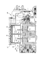
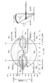
- FIG. 2 is an enlarged cross-sectional view of one bank cut by a cut surface including a rotation axis of a crankshaft and a cylinder axis in a V-type engine.
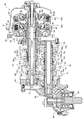
- FIG. 3 is an enlarged cross-sectional view of the transmission cut at the cut surface including the axial centers of the main shaft and the counter shaft.
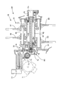
- FIG. 4 is an enlarged cross-sectional view of the shift control device cut at the cut surface including the rotation axis of the shift drum.
- FIG. 1 is a side view schematically showing an overall image of a motorcycle according to an embodiment of the present invention.
- FIG. 2 is an enlarged cross-sectional view of one bank cut by a cut surface including a rotation axis of a crankshaft and a cylinder axis in a V-type engine.
- FIG. 3 is an enlarged cross-sectional view of the transmission cut at the cut surface including
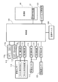
- FIG. 5 is a block diagram schematically showing the configuration of a control system for a motorcycle.
- FIG. 6 is a graph showing a two-dimensional distribution of the roll angle and the angular velocity of the roll angle actually measured by a motorcycle.
- FIG. 7 is a graph showing changes in the threshold value of the roll angle.
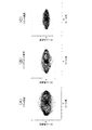
- FIG. 8 is a graph corresponding to FIG. 6 and showing a two-dimensional distribution of a roll angle and an angular velocity of a roll angle actually measured on a dry road surface, a slightly wet road surface, and a wet road surface.
- top, bottom, front, back, left, and right of the vehicle body are defined based on the line of sight of the occupant riding the motorcycle.
- FIG. 1 schematically shows an overall image of a motorcycle according to an embodiment of the present invention.
- the motorcycle 11 includes a vehicle body frame 12 and a vehicle body cover 13 mounted on the vehicle body frame 12.
- the vehicle body cover 13 has a front cowl 14 that covers the vehicle body frame 12 from the front, and a tank cover 17 that is continuous from the outer surface of the fuel tank 15 to the front and is connected to the occupant seat 16 behind the fuel tank 15. Fuel is stored in the fuel tank 15. When driving the motorcycle 11, the occupant straddles the occupant seat 16.
- the body frame 12 includes a head pipe 18, a pair of left and right main frames 21 extending rearward from the head pipe 18 and having a pivot plate 19 at the rear lower end, and a position below the main frame 21 below the head pipe 18. It has a down frame 22 extending to and integrated with the main frame 21.
- the front fork 23 is supported on the head pipe 18 so that it can be steered freely.
- the front wheel WF is rotatably supported on the front fork 23 around the axle 24.
- a steering handle 25 is coupled to the upper end of the front fork 24. The driver grips the left and right grips of the steering wheel 25 when driving the motorcycle 11.
- a swing arm 27 is connected to the vehicle body frame 12 at the rear of the vehicle so as to swing up and down around the pivot 26.
- the rear wheel WR is rotatably supported around the axle 28 at the rear end of the swing arm 27.
- a power unit 29 that generates power transmitted to the rear wheel WR is mounted on the vehicle body frame 12 between the front wheel WF and the rear wheel WR.
- the power unit 29 is connected to and supported by the down frame 22 and the main frame 21. The power of the power unit 29 is transmitted to the rear wheel WR via the drive shaft 31.
- the power unit 29 includes a V-type engine having a front bank located in front of the vehicle body frame 12 and a rear bank located behind the front bank. As shown in FIG. 2, the engine 32 is coupled to a crankcase 34 that rotatably supports one crankshaft 33 in both the front bank and the rear bank, and a crankcase 34 for each of the front bank and the rear bank.
- a cylinder block 36 for partitioning the cylinder bore 35 and a cylinder head 37 coupled to the cylinder block 36 to close the cylinder bore 35 are provided.
- the piston 38 is housed in the cylinder bore 35 so as to be linearly reciprocating.
- a combustion chamber 39 is partitioned between the piston 38 and the cylinder head 37.
- a connecting rod 41 connected to the crankshaft 33 is connected to the piston 38.
- the reciprocating linear motion of the piston 38 is converted into the rotational motion of the crankshaft 33 by the action of the crank.
- One end of the crankshaft 33 projects from the crankcase 34 into the cam chain chamber 42.
- a drive gear 43 is fixed to one end of the crankshaft 33 in the camshane chamber 42.
- a pulsar ring 44 is fixed to the drive gear 43 coaxially with the rotation axis Rx of the crankshaft 33. Retractors are formed at equal intervals along the outer circumference of the pulsar ring 44.
- a pulsar sensor 45 that detects the number of revolutions (per minute) of the crankshaft 33 based on the pulse signal generated by the retractor is faced to the retractor.
- the power unit 29 is incorporated in the crankcase 34 and includes a transmission 46 that transmits the power of the crankshaft 33 to the drive shaft 31.
- the transmission 46 is rotatable around an axis parallel to the rotation axis Rx of the crankshaft 33, and is rotatable around a main shaft (drive shaft) 47 supported by the crankcase 34 and an axis parallel to the axis of the main shaft 47. Is provided with a counter shaft 48 (driven shaft) supported by the crankcase 34.
- gear trains that can be selectively established, that is, 1st gear train G1, 2nd gear train G2, 3rd gear train G3, 4th gear train G4, 5
- a speed gear train G5 and a speed gear train G6 are arranged.
- the main shaft 47 is composed of an inner shaft 47a that is rotatably supported by the crankcase 34 around the axis and a sleeve 47b that is coaxially mounted on the inner shaft 47a and rotatably mounted on the inner shaft 47a.
- the 1st gear train G1 includes a drive gear 49a coaxially fixed to the inner shaft 47a and a driven gear 49b coaxially mounted on the counter shaft 48 so as to be rotatable relative to the drive gear 49a.
- the drive gear 49a is integrally formed with the inner shaft 47a.
- the driven gear 49b is connected to the counter shaft 48 so as not to be relatively displaceable in the axial direction of the counter shaft 48.
- the 5-speed gear train G5 includes a drive gear 51a coaxially mounted on the inner shaft 47a so as to be relatively rotatable, and a driven gear 51b coaxially coupled to the counter shaft 48 so as not to rotate relative to the drive gear 51a. ..
- the drive gear 51a is supported by the inner shaft 47a so as not to be displaced in the axial direction of the inner shaft 47a.
- the driven gear 51b is coupled to a first shifter 52 that is spline-coupled on the counter shaft 48 so as to be axially relative to each other.
- the dowel of the first shifter 52 is connected to the driven gear 49b of the first gear train G1. In this way, power is transmitted from the inner shaft 47a to the counter shaft 48 via the first gear train G1.
- the 1st speed is established.
- the third gear train G3 includes a drive gear 53a coaxially coupled to the inner shaft 47a so as not to rotate relative to each other, and a driven gear 53b coaxially mounted to the counter shaft 48 so as to be relatively rotatable.
- the drive gear 53a is coupled to a second shifter 54 which is spline-coupled on the inner shaft 47a so as to be displaced relative to the axial direction.
- the driven gear 53b is connected to the counter shaft 48 so as not to be relatively displaceable in the axial direction of the counter shaft 48.
- the first shifter 52 moves from the neutral position to the second in the opposite direction to the first direction DR1.
- the drive gear 51a and the driven gear 51b are disengaged, and the dowel of the first shifter 52 is connected to the driven gear 53b of the third gear train G3. In this way, power is transmitted from the inner shaft 47a to the counter shaft 48 via the third gear train G3. The 3rd speed is established.
- the second gear train G2 includes a drive gear 55a coaxially fixed to the sleeve 47b and a driven gear 55b coaxially mounted on the counter shaft 48 so as to be rotatable relative to the drive gear 55a and meshed with the drive gear 55a.
- the drive gear 55a is integrally formed with the sleeve 47b.
- the driven gear 55b is connected to the counter shaft 48 so as not to be relatively displaceable in the axial direction of the counter shaft 48.
- the 6-speed gear train G6 includes a drive gear 56a that is coaxially mounted on the sleeve 47b so as to be relatively rotatable, and a driven gear 56b that is coaxially coupled to the counter shaft 48 so as not to be relatively rotatable and meshes with the drive gear 56a.
- the drive gear 56a is non-displaceable in the axial direction of the sleeve 47b and is supported by the sleeve 47b.
- the driven gear 56b is coupled to a third shifter 57 which is spline-coupled on the counter shaft 48 so as to be axially relative to each other.
- the 4-speed gear train G4 includes a drive gear 58a coaxially coupled to the sleeve 47b so as not to rotate relative to each other, and a driven gear 58b coaxially mounted to the counter shaft 48 so as to be relatively rotatable.
- the drive gear 58a is coupled to a fourth shifter 59 which is spline-coupled on the sleeve 47b so as to be axially relative to each other.
- the driven gear 58b is connected to the counter shaft 48 so as not to be relatively displaceable in the axial direction of the counter shaft 48.
- the transmission 46 includes a shift control device 61 that sequentially switches gears to neutral, 1st gear, 2nd gear, 3rd gear, 4th gear, 5th gear, and 6th gear. Be prepared.
- the shift control device 61 includes a shift drum 62 that rotates around a rotation axis Dx parallel to the axis of the main shaft 47 and the axis of the counter shaft 48, and a first shift fork 63 and a first shift fork 63 that is parallel to the rotation axis Dx of the shift drum 62.
- a first cam groove 62a that meshes with the first shift fork 63 and causes the first shift fork 63 to be displaced along the first guide shaft 65 according to the rotation of the shift drum 62.
- the second cam groove 62b which meshes with the second shift fork 66 and causes the displacement of the second shift fork 66 along the second guide shaft 68 according to the rotation of the shift drum 62, meshes with the third shift fork 64.
- the third cam groove 62c which causes the displacement of the third shift fork 64 along the first guide shaft 65 according to the rotation of the shift drum 62, meshes with the fourth shift fork 67, and the third cam groove 62c meshes with the fourth shift fork 67 according to the rotation of the shift drum 62.
- a fourth cam groove 62d that causes displacement of the fourth shift fork 67 is formed along the guide shaft 68.
- the first shift fork 63 is connected to the first shifter 52 so as to be relatively rotatable around the counter shaft 48.
- the second shift fork 66 is connected to the second shifter 54 so as to be relatively rotatable around the inner shaft 47a.
- the third shift fork 64 is connected to the third shifter 57 so as to be relatively rotatable around the counter shaft 48.
- the fourth shift fork 67 is connected to the fourth shifter 59 so as to be relatively rotatable around the sleeve 47b.
- the displacement of the fourth shifter 59 in the axial direction is caused on the inner shaft 47b.
- an electric motor 71 is connected to the shift drum 62 via a power transmission mechanism 69.
- the power transmission mechanism 69 is coupled to a transmission shaft 72 that penetrates the center of the shift drum 62 coaxially with the shift drum 62 and one end of the transmission shaft 72, and engages with pins at equal intervals around the rotation axis Dx of the transmission shaft 72.
- a barrel cam 75 that causes rotation of the transmission shaft 72 is provided. The driving force is transmitted from the electric motor 71 to the barrel cam 75 via the reduction gear mechanism 69.
- the shift drum 62 is connected to the transmission shaft 72 by a lost motion spring 76.
- the lost motion spring 76 is composed of a torsion spring that is wound around a transmission shaft 72 and exerts an elastic force around the transmission shaft 72.
- the shift drum 62 follows the rotation of the transmission shaft 72 by the action of the elastic force of the lost motion spring 76.
- a shift sensor 77 that detects the rotation angle of the shift drum 62 is connected to the shift drum 62.
- the shift sensor 77 detects the rotation of the detection shaft 78 that rotates around the axis parallel to the rotation axis Dx of the shift drum 62. Rotation is transmitted from the shift drum 62 to the detection shaft 78 via the reduction gear train 79.
- the first clutch 82a and the second clutch 82b that share the clutch outer 81 are connected to the main shaft 47.
- the clutch outer 81 is formed of a cylindrical body coaxial with the main shaft 47.
- a driven gear 83 coaxially and relatively rotatably supported on the sleeve 47b is coupled to the clutch outer 81 via a damper spring 84.
- the driven gear 83 meshes with the drive gear 43 on the crankshaft 33.
- the power of the crankshaft 33 is transmitted to the clutch outer 81 via the drive gear 43 and the driven gear 83.
- the first clutch 82a faces the first clutch inner 85, which is coaxially surrounded by the clutch outer 81 and is coupled to the inner shaft 47a so as not to rotate relative to the inner shaft 47a, and the pressure receiving plate of the first clutch inner 85 in the axial direction. It is arranged between the pressing body 86 supported on the first clutch inner 85 and the pressure receiving plate and the pressing body 86 so as to be rotatable in the axial direction of the inner shaft 47a, and is freely displaced in the axial direction and cannot rotate relative to the clutch outer 81.
- the drive friction plate 87 is connected to the drive friction plate 87, and the driven friction plate 88 is arranged alternately with the drive friction plate 87 in the axial direction and is connected to the first clutch inner 85 so as to be axially displaceable and relatively non-rotatable. ..
- a hydraulic chamber 89 that generates a hydraulic pressure that causes displacement of the pressing body 86 toward the pressure receiving plate is formed.
- a spring 91 that exerts an elastic force on the pressing body 86 is arranged between the first clutch inner 85 and the pressing body 86 in a direction in which the volume of the hydraulic chamber 89 is reduced in response to the decompression of the hydraulic chamber 89.
- the second clutch 82b is axially opposed to the pressure receiving plate of the second clutch inner 92 and the second clutch inner 92, which is coaxially surrounded by the clutch outer 81 and coupled to the sleeve 47b so as not to rotate relative to the sleeve 47b. It is arranged between the pressing body 93 supported on the second clutch inner 92 and the pressure receiving plate and the pressing body 93 so as to be displaced in the axial direction of 47b, and is connected to the clutch outer 81 so as to be axially displaceable and relatively non-rotatable.
- the driven friction plate 94 is provided with a driven friction plate 94 which is arranged alternately with the drive friction plate 94 in the axial direction and is connected to the second clutch inner 92 so as to be axially displaceable and relatively non-rotatable.
- a hydraulic chamber 96 that generates a hydraulic pressure that causes displacement of the pressing body 93 toward the pressure receiving plate is formed.
- a spring 97 that exerts an elastic force on the pressing body 93 is arranged between the second clutch inner 92 and the pressing body 93 in a direction in which the volume of the hydraulic chamber 96 is reduced in response to the decompression of the hydraulic chamber 96.
- a drive bevel gear 98 is coaxially fixed to the counter shaft 48 on the outside of the crankcase 34.
- a driven bevel gear 99 that rotates around an axis orthogonal to the rotation axis of the counter shaft 48 meshes with the drive bevel gear 98.
- An output shaft 101 connected to the drive shaft 31 is integrally formed on the driven bevel gear 99.
- the motorcycle 11 detects the vehicle speed, the first detection unit 111 that detects the size of the roll angle of the vehicle body, the second detection unit 112 that detects the angular velocity of the roll angle of the vehicle body, and the vehicle speed.
- the operation of the transmission 46 is controlled based on the third detection unit 113, the fourth detection unit 114 that detects the acceleration in the forward direction of the vehicle body, the magnitude of the roll angle, the angular velocity of the roll angle, the vehicle speed, and the acceleration in the forward direction.
- the control unit 115 is provided.
- An inertial sensor 116 (for example, a gyro sensor) is commonly connected to the first detection unit 111 and the second detection unit 112.
- the inertial sensor 116 is connected to the engine 32, for example, and is arranged on the upper surface of an air cleaner that filters the air supplied to the combustion chamber 39.
- the inertial sensor 116 detects the roll angle of the vehicle body and its angular velocity according to the inclination of the vehicle body in the left-right direction.
- a signal for specifying the magnitude of the roll angle is supplied from the inertial sensor 116 to the first detection unit 111.
- a signal for specifying the angular velocity of the roll angle is supplied from the inertial sensor 116 to the second detection unit 112.
- the roll angle corresponds to the rotation angle around the axis extending horizontally in the front-rear direction of the vehicle body through the center of gravity of the vehicle body.
- the first detection unit 111 and the second detection unit 112 may function as input ports of the control unit 115.
- a vehicle speed sensor 117 is commonly connected to the third detection unit 113 and the fourth detection unit 114.
- the vehicle speed sensor 117 detects the vehicle speed based on, for example, the rotational speed of the front wheel WF.
- a signal for identifying the vehicle speed is supplied from the vehicle speed sensor 117 to the third detection unit 113.
- the fourth detection unit 114 calculates the acceleration in the forward direction based on, for example, the differential value of the vehicle speed.
- the third detection unit 113 and the fourth detection unit 114 may function as input ports of the control unit 115.
- the control unit 115 is connected to, for example, a mode switch 118 operated for switching between fully automatic shifting and semi-automatic shifting, and a shift switch 119 operated for selecting a shift stage when semi-automatic shifting is selected.
- a mode switch 118 operated for switching between fully automatic shifting and semi-automatic shifting
- a shift switch 119 operated for selecting a shift stage when semi-automatic shifting is selected.
- the control unit 115 selects fully automatic shifting.
- the transmission 46 automatically shifts up and down based on the vehicle speed and the acceleration in the forward direction. It is not necessary for the driver to operate the clutch or shift when shifting.
- the "MT" button 118b is operated by the mode switch 118, the control unit 115 selects semi-automatic shifting.
- the mode switch 118 and the shift switch 119 may be installed on the steering handle 25 within a range that can be reached by the fingers of the hand holding the grip of the steering handle 25, for example.
- a fifth detection unit 121 that detects the wheel speed of the rear wheel WR is connected to the control unit 115.
- a wheel speed sensor 122 that detects the rotational speed of the rear wheel WR is connected to the fifth detection unit 121.
- a signal for specifying the rotation speed of the rear wheel WR is supplied from the wheel speed sensor 122 to the fifth detection unit 121.
- a traction changing device 123 for adjusting the traction of the rear wheel WR is connected to the control unit 115.
- the traction changing device 123 can be composed of, for example, a throttle bubble of the engine 31 or a braking system of the rear wheel WR.
- the traction changing device 123 suppresses the traction of the rear wheel WR.
- the control unit 115 can control the operation of the traction changing device 123 based on the vehicle speed and the wheel speed of the rear wheel WR.
- a storage device 124 is connected to the control unit 115.
- the storage device 124 stores a map that defines an angular velocity that prohibits shifting of the transmission 46 for each size of the roll angle.
- the roll angle shows 0 degrees at the neutral position (upright position) of the vehicle body.
- the roll angle increases with a positive value.
- the roll angle increases with a negative value.
- the map when the roll angle is in the positive range and the angular velocity of the roll angle is positive (acceleration that collapses to the right), the transmission 46 is prohibited from shifting.
- the transmission of the transmission 46 is prohibited from shifting.
- the transmission 46 is prohibited from shifting.
- the angular velocity of the roll angle exceeds the reference value PR of the positive value in the range of the negative value
- the transmission of the transmission 46 is prohibited.
- the absolute value of the roll angle exceeds the threshold value TH, shifting of the transmission 46 is prohibited.
- FIG. 6 shows a two-dimensional distribution of the roll angle and the angular velocity of the roll angle actually measured when the motorcycle 11 is running. It is understood that the angular velocity is maximized at the neutral position specified by the roll angle when the vehicle body is tilted from the right bank state to the left bank state or from the left bank state to the right bank state. On the other hand, it is understood that the angular velocity converges to zero at the neutral position specified by the roll angle in the "falling down” that collapses from the neutral position to the left and right and the “body raising” that returns from the collapsed position to the neutral position. ..
- the roll angle threshold TH and the reference values PL and PR of the angular velocity can be set based on the measured two-dimensional distribution of the roll angle and the angular velocity.
- a drive signal is supplied from the control unit 115 to the electric motor 71 of the shift control device 61.
- the electric motor 71 drives the shift drum 62 around the rotation axis Dx according to the supply of the drive signal.
- the first shift fork 63 is displaced along the first guide shaft 65 according to the rotation of the shift drum 62.
- the first shifter 52 is displaced from the neutral position to the first direction DR1.
- the first shifter 52 is coupled to the driven gear 49b of the first gear train G1. Rotation is transmitted from the inner shaft 47a to the counter shaft 48 according to the engagement of the drive gear 49a and the driven gear 49b of the first gear train G1.
- a drive signal is supplied from the control unit 115 to the electric motor 71 of the shift control device 61.
- the electric motor 71 drives the shift drum 62 around the rotation axis Dx according to the supply of the drive signal.
- the third shift fork 64 is displaced along the first guide shaft 65 according to the rotation of the shift drum 62.
- the third shifter 57 is displaced from the neutral position to the second direction DR2.
- the third shifter 57 is coupled to the driven gear 55b of the second gear train G2. Rotation is transmitted from the sleeve 47b to the counter shaft 48 according to the engagement of the drive gear 55a and the driven gear 55b of the second gear train G2.
- the hydraulic chamber 89 of the first clutch 82a is depressurized and the oil pressure is supplied to the hydraulic chamber 96 of the second clutch 82b.
- the pressing body 86 moves away from the pressure receiving plate in the second direction DR2.
- the pressing body 93 approaches the pressure receiving plate in the first direction DR1. In this way, the coupling between the clutch outer 81 and the inner shaft 47a is released, and the clutch outer 81 and the sleeve 47b are coupled around the rotation axis.
- the first clutch 82a is disengaged and the second clutch 82b is connected. In the engine 32, the second speed stage is established.
- the upshift and downshift of the transmission 46 are realized according to the drive of the electric motor 71 and the connection and disconnection of the first clutch 82a and the second clutch 82b.
- the transmission 46 transmits power from the main shaft 47 to the counter shaft 48 while automatically shifting between the main shaft 47 (drive shaft) and the counter shaft 48 (driven shaft).
- the control unit 115 establishes the automatic transmission mode based on the signal supplied from the "AT" button 118a.
- the control unit 115 determines upshifts and downshifts of the transmission 46 based on the vehicle speed, the throttle opening degree, and the acceleration in the forward direction.
- the control unit 115 refers to the size of the roll angle and the angular velocity of the roll angle. The driver can enjoy riding without worrying about upshifts and downshifts.
- the control unit 115 executes upshifting and downshifting of the transmission 46 based on the vehicle speed, the throttle opening degree, and the acceleration in the forward direction. The driver can enjoy riding without feeling an excessive hold when accelerating.
- the control unit 115 detects the positive angular velocity in the range of the positive roll angle. Alternatively, the control unit 115 detects a negative angular velocity in the range of the negative roll angle. The control unit 115 compares the size of the roll angle and the angular velocity of the roll angle with the map of the storage device 124. As a result, the control unit 115 prohibits the transmission 46 from shifting up. The running feeling of the motorcycle 11 is improved by prohibiting the shift-up of the transmission 46 when the vehicle body falls down.
- the control unit 115 When turning to the left or right, the angular velocity of the roll angle occurs from the position where the vehicle body collapses to the neutral position.
- the control unit 115 detects a negative angular velocity larger than the reference value PL in the range of the positive roll angle.
- the control unit 115 detects a positive angular velocity larger than the reference value PR in the range of the negative roll angle.
- the control unit 115 compares the size of the roll angle and the angular velocity of the roll angle with the map of the storage device 124. As a result, the control unit 115 prohibits the transmission 46 from shifting up. By prohibiting the upshifting of the speed machine 46 when turning to the left or right, the running feeling of the motorcycle 11 is improved.
- the control unit 115 detects a negative angular velocity that includes the reference value PL within the range of the positive roll angle and is smaller than the reference value PL.
- the control unit 115 detects a positive angular velocity that includes the reference value PR in the range of the negative roll angle and is smaller than the reference value PR.
- the control unit 115 compares the size of the roll angle and the angular velocity of the roll angle with the map of the storage device 124. As a result, the control unit 115 allows the transmission 46 to shift up. If the upshift is executed, the motorcycle 11 can get out of the cornering run and accelerate immediately. The running feeling of the motorcycle 11 can be improved. The driver can enjoy riding even more.
- the control unit 115 When the "MT" button 118b is operated by the mode switch 118, the control unit 115 establishes the semi-automatic shift mode based on the signal supplied from the "MT" button 118b. In the semi-automatic shift mode, the control unit 115 determines the shift up and down of the transmission 46 based on the operation of the shift switch 119. The driver can enjoy riding without being bothered by the operation of the clutch when shifting gears. In the semi-automatic shifting mode, the prohibition of shifting based on the size of the roll angle and the angular velocity does not apply. That is, the driver's intention is applied with the highest priority.
- the threshold value TH of the absolute value of the roll angle is changed according to the magnitude of the acceleration in the forward direction.
- the threshold TH is switched between acceleration and non-acceleration. Acceleration and non-acceleration may be separated by a predetermined threshold value.
- the threshold TH of the absolute value of the roll angle is set large.
- the threshold value TH of the absolute value of the roll angle is set larger as the vehicle speed increases.
- the control unit 115 changes the intervention intensity of the traction control based on the roll angle and the angular velocity of the roll angle.
- the control unit 115 estimates the friction coefficient ⁇ of the road surface based on the size of the roll angle and the angular velocity of the roll angle.
- the threshold value composed of the speed difference between the vehicle speed and the wheel speed of the rear wheel WR is set small.
- the degree of deceleration of the rear wheel WR is also increased.
- the acceleration of the idling of the rear wheel WR is large, so that the traction control is executed at an early stage and the increase of the idling of the rear wheel WR can be suppressed.
- the control unit 115 has a dry road surface having a first friction coefficient, a slightly wet surface having a second friction coefficient smaller than the first friction coefficient, and a second surface based on the distribution of the roll angle and the angular velocity. It can be distinguished from the wet surface of the third friction coefficient, which is smaller than the friction coefficient.
- the size of the roll angle is referred to in addition to the angular velocity of the roll angle in the shift control, so that the motorcycle falls to the left and right (formation of a bank), turns back to the left and right, and falls. It can be determined separately from the return to the neutral position. In this way, the control of the transmission can be executed while responding to the situation of the vehicle body in detail.
- the running feeling of the motorcycle 11 is improved. The driver can enjoy riding even more.
- control unit 115 When the control unit 115 according to the present embodiment detects an angular velocity in the direction of falling from the neutral position of the vehicle body, the control unit 115 prohibits the transmission of the transmission 46 from shifting. When entering a corner or turning to the left or right, the angular velocity of the roll angle occurs in the direction of falling from the neutral position of the vehicle body. In such a case, it is desired that the shift-up of the transmission 46 is prohibited.
- the running feeling of the motorcycle 11 can be improved by prohibiting the shift-up of the transmission 46 when the vehicle body falls down.
- the control unit 115 detects a roll angle larger than the threshold value TH in the direction of falling from the neutral position of the vehicle body, the control unit 115 prohibits shifting of the transmission 46.
- the control unit 115 detects a roll angle larger than the threshold value TH in the direction of falling from the neutral position of the vehicle body, the control unit 115 prohibits shifting of the transmission 46.
- the roll angle exceeds the threshold value TH in the direction of falling from the neutral position of the vehicle body, it can be determined that the motorcycle 11 is in cornering. It is desirable that the shift-up of the transmission 46 is prohibited during the cornering run. By prohibiting the shift-up of the transmission 46 during the cornering run, the running feeling of the motorcycle 11 can be improved.
- control unit 115 changes the threshold value TH according to the magnitude of acceleration in the forward direction.
- the control unit 115 When the control unit 115 detects an angular velocity exceeding the reference values PL and PR in the direction of returning from the collapsed position to the neutral position, the control unit 115 prohibits the transmission 46 from shifting.
- a large angular velocity exceeding the reference values PL and PR occurs when the vehicle body returns from the collapsed position to the neutral position. It is desirable that shifting of the transmission 46 is prohibited when switching to the left or right.
- the angular velocity of the roll angle including the reference values PL and PR, remains smaller than the reference values PL and PR when the vehicle body returns from the collapsed position to the neutral position, such as when shifting from winding running to straight running. ..
- the motorcycle 11 can get out of the winding running and accelerate immediately. The running feeling of the motorcycle 11 can be improved. The driver can enjoy riding even more.
- the motorcycle 11 includes a storage device 124 that stores a map that defines an angular velocity that prohibits shifting of the transmission 46 for each size of the roll angle. Since the magnitude and angular velocity of the roll angle for prohibiting the shift-up of the transmission 46 are uniquely quantified, the execution of the control for prohibiting the shift of the transmission 46 can be simplified.
- the inertial sensor 116 detects the magnitude of the roll angle and the angular velocity. Since the prohibition of shift-up is controlled based on the information obtained by the single inertial sensor 116, the configuration of the shift control device 61 can be simplified.
- the control unit 115 changes the intervention intensity of the traction control based on the roll angle and the angular velocity of the roll angle.
- Road surface conditions can be predicted based on the magnitude of the roll angle and the angular velocity.
- control unit 115 may refer to the rotation speed of the engine 32 when prohibiting the shift up. In this case, the control unit 115 releases the prohibition of shifting when the engine speed exceeds a predetermined value. Even if the condition for prohibiting shifting is satisfied, if the engine speed is high, the driving feeling of the motorcycle can be improved by executing the shift up.
- the aforementioned threshold TH may be changed based on the estimated cornering radius estimated by the centrifugal acceleration ⁇ y and the vehicle speed. Further, when it is determined that the estimated cornering radius is smaller than the predetermined value, the control unit 115 may prohibit the shift. As a result, shifting is prohibited even during fine cornering, and the operability of the vehicle body can be improved.
Landscapes
- Engineering & Computer Science (AREA)
- General Engineering & Computer Science (AREA)
- Mechanical Engineering (AREA)
- Control Of Transmission Device (AREA)
- Control Of Vehicle Engines Or Engines For Specific Uses (AREA)
Abstract
自動二輪車は、駆動軸および従動軸の間で自動的に変速しながら駆動軸から従動軸に動力を伝達する変速機と、車体のロール角の大きさを検出する第1検出部(111)と、車体のロール角の角速度を検出する第2検出部(112)と、ロール角の大きさおよび角速度に基づき、変速機で変速を禁止する制御部(115)とを備える。これにより、さらにきめ細かく車体の状況に応じて変速制御を実行することができる自動二輪車を提供する。
Description
本発明は、駆動軸および従動軸の間で自動的に変速しながら駆動軸から従動軸に動力を伝達する変速機と、変速機で変速を禁止する制御部とを備える自動二輪車に関する。
特許文献1は自動二輪車を開示する。変速制御装置は、車体のロール角の角速度を検出するロール角速度センサーと、ハンドルの操舵角の角速度を検出する操舵角速度センサーとを備える。ワインディング走行時など、ロール角の角速度が基準値を超え、操舵角の角速度が基準値を超えると、変速制御装置は変速を禁止する。その結果、ワインディング走行時に車輪の駆動力が一定に維持されて良好な旋回動作は実現されることができる。
ワインディング走行から直線走行に移行する際に、運転手は車体を起こしてすぐさま加速したいと考える。しかしながら、特許文献1に記載の変速制御装置では、直線走行に移行する直前までロール角の角速度および操舵角の角速度はともに基準値を超えることから、シフトアップすることができず、運転手は思い通りに自動二輪車を加速させることができない。
本発明は、上記実状に鑑みてなされたもので、さらにきめ細かく車体の状況に応じて変速制御を実行することができる自動二輪車を提供することを目的とする。
本発明の第1側面によれば、駆動軸および従動軸の間で自動的に変速しながら前記駆動軸から前記従動軸に動力を伝達する変速機と、車体のロール角の大きさを検出する第1検出部と、前記車体の前記ロール角の角速度を検出する第2検出部と、前記ロール角の大きさおよび前記角速度に基づき、前記変速機で変速を禁止する制御部とを備える自動二輪車が提供される。
第2側面によれば、第1側面の構成に加えて、前記制御部は、前記車体の中立位置から倒れ込む方向に前記角速度を検出すると、前記変速機の変速を禁止する。
第3側面によれば、第2側面の構成に加えて、前記制御部は、前記車体の中立位置から倒れ込む方向に閾値を超える前記ロール角を検出すると、前記変速機の変速を禁止する。
第4側面によれば、第3側面の構成に加えて、前記制御部は、前進方向の加速度の大きさに応じて前記閾値を変更する。
第5側面によれば、第2~第4側面のいずれか1の構成に加えて、前記制御部は、倒れ込んだ位置から中立位置に復帰する方向に基準値を超える前記角速度を検出すると、前記変速機の変速を禁止する。
第6側面によれば、第1~第5側面のいずれか1の構成に加えて、自動二輪車は、前記ロール角の大きさごとに前記変速機の変速を禁止する前記角速度を規定するマップを格納する記憶デバイスを備える。
第7側面によれば、第1~第6側面のいずれか1の構成に加えて、自動二輪車は、前記ロール角の大きさおよび前記角速度を検出する慣性センサーを備える。
第8側面によれば、第1~第7側面のいずれか1の構成に加えて、前記制御部は、前記ロール角および前記角速度に基づきトラクションコントロールの介入強度を変更する。
第9側面によれば、第1~第8側面のいずれか1の構成に加えて、前記制御部は、エンジン回転数が所定値を超えた場合には前記変速の禁止を解除する。
第1側面によれば、ロール角の角速度に加えてロール角の大きさが参照されることで、左右への倒れ込み(バンクの形成)や左右への切り返しと、倒れ込みから中立位置への復帰とは切り分けて判定されることができる。こうして車体の状況にきめ細かく対応しながら変速機の制御は実行されることができる。自動二輪車の走行感は向上する。運転者はライディングをさらに楽しむことができる。
第2側面によれば、コーナーに進入する際や左右への切り返し時には車体の中立位置から倒れ込む方向にロール角の角速度は生じる。こういった場合には変速機の変速は禁止されることが望まれる。車体が倒れ込む際に変速機の変速が禁止されることで自動二輪車の走行感は向上することができる。
第3側面によれば、車体の中立位置から倒れ込む方向にロール角が閾値を超えると、自動二輪車はコーナリング走行中と判断されることができる。コーナリング走行中には変速機の変速は禁止されることが望まれる。コーナリング走行中に変速機の変速が禁止されることで自動二輪車の走行感は向上することができる。
第4側面によれば、コーナリング走行中であっても車両が加速できる状態の場合には変速機でシフトアップが実行されると、変速段の過剰なホールド感は解消されることができる。
第5側面によれば、例えば右バンク状態から左バンク状態に車体を傾ける左右への切り返しでは、車体が倒れ込んだ位置から中立位置に復帰する際に基準値を超える大きな角速度が生じる。左右への切り返し時には変速機の変速は禁止されることが望まれる。その一方で、ワインディング走行から直線走行に移行する際など、車体が倒れ込んだ位置から中立位置に復帰する際にロール角の角速度は基準値以下に留まる。このとき、シフトアップが実行されれば、自動二輪車はワインディング走行から抜けて即座に加速することができる。自動二輪車の走行感は向上することができる。運転者はライディングをさらに楽しむことができる。
第6側面によれば、変速機の変速を禁止するロール角の大きさおよび角速度は一義的に数値化されることができることから、変速機の変速を禁止する制御の実行は簡素化されることができる。
第7側面によれば、単一の慣性センサーによって得られる情報に基づき変速の禁止は制御されることから、変速制御装置の構成は簡素化されることができる。
第8側面によれば、ロール角の大きさおよび角速度に基づき路面状況は予測されることができる。予測される路面状況に応じてトラクションコントロールを実行することで、自動二輪車の走行感は向上することができる。運転者はライディングをさらに楽しむことができる。
第9側面によれば、変速禁止の条件が成立した場合でも、エンジン回転数が高い場合にはシフトアップを実行することで、自動二輪車の走行感は向上することができる。
11…自動二輪車
46…変速機
47…駆動軸(メインシャフト)
48…従動軸(カウンターシャフト)
111…第1検出部
112…第2検出部
115…制御部
116…慣性センサー
124…記憶デバイス
PL…基準値
PR…基準値
TH…閾値
46…変速機
47…駆動軸(メインシャフト)
48…従動軸(カウンターシャフト)
111…第1検出部
112…第2検出部
115…制御部
116…慣性センサー
124…記憶デバイス
PL…基準値
PR…基準値
TH…閾値
以下、添付図面を参照しつつ本発明の実施形態を説明する。ここで、車体の上下前後左右は自動二輪車に乗車した乗員の目線に基づき規定されるものとする。
図1は本発明の一実施形態に係る自動二輪車の全体像を概略的に示す。自動二輪車11は、車体フレーム12と、車体フレーム12に装着された車体カバー13とを備える。車体カバー13は、前方から車体フレーム12を覆うフロントカウル14と、燃料タンク15の外面から前方に連続し、燃料タンク15の後方の乗員シート16に接続されるタンクカバー17とを有する。燃料タンク15に燃料は貯留される。自動二輪車11の運転にあたって乗員は乗員シート16を跨ぐ。
車体フレーム12は、ヘッドパイプ18と、ヘッドパイプ18から後ろ下がりに延びて、後下端にピボットプレート19を有する左右1対のメインフレーム21と、メインフレーム21の下方の位置でヘッドパイプ18から下方に延び、メインフレーム21に一体化されるダウンフレーム22とを有する。
ヘッドパイプ18には操向自在にフロントフォーク23が支持される。フロントフォーク23には車軸24回りで回転自在に前輪WFが支持される。フロントフォーク24の上端には操向ハンドル25が結合される。運転者は自動二輪車11の運転にあたって操向ハンドル25の左右端のグリップを握る。
車両の後方で車体フレーム12にはピボット26回りで上下に揺動自在にスイングアーム27が連結される。スイングアーム27の後端に車軸28回りで回転自在に後輪WRが支持される。前輪WFと後輪WRとの間で車体フレーム12には後輪WRに伝達される動力を生成する動力ユニット29が搭載される。動力ユニット29はダウンフレーム22およびメインフレーム21に連結されて支持される。動力ユニット29の動力はドライブシャフト31を経て後輪WRに伝達される。
動力ユニット29は、車体フレーム12への搭載時に前方に位置する前バンクと、前バンクよりも後方に位置する後バンクとを有するV型エンジンを備える。図2に示されるように、エンジン32は、前バンクおよび後バンクに共通に1つのクランクシャフト33を回転自在に支持するクランクケース34と、前バンクおよび後バンクごとにクランクケース34に結合されて、シリンダーボア35を区画するシリンダーブロック36と、シリンダーブロック36に結合されてシリンダーボア35を塞ぐシリンダーヘッド37とを備える。シリンダーボア35には線形往復運動自在にピストン38が収容される。ピストン38とシリンダーヘッド37との間には燃焼室39が区画される。燃焼室39内で混合気の吸入、混合気の圧縮、混合気の燃焼および排ガスの排気が繰り返される。こうして混合気の燃焼に基づきピストン38の往復線形運動は引き起こされる。
ピストン38には、クランクシャフト33に連結されるコネクティングロッド41が接続される。クランクの働きでピストン38の往復線形運動はクランクシャフト33の回転運動に変換される。クランクシャフト33の一端はクランクケース34からカムチェーン室42に突出する。カムシェーン室42内でクランクシャフト33の一端には駆動歯車43が固定される。
駆動歯車43には、クランクシャフト33の回転軸線Rxに同軸にパルサーリング44が固定される。パルサーリング44には外周に沿って等間隔にリラクターが形成される。リラクターには、リラクターで生成されるパルス信号に基づきクランクシャフト33の(1分当たり)回転数を検出するパルサーセンサー45が向き合わせられる。
図3に示されるように、動力ユニット29は、クランクケース34内に組み込まれて、ドライブシャフト31にクランクシャフト33の動力を伝達する変速機46を備える。変速機46は、クランクシャフト33の回転軸線Rxに平行な軸線回りに回転自在にクランクケース34に支持されるメインシャフト(駆動軸)47と、メインシャフト47の軸線に平行な軸線回りで回転自在にクランクケース34に支持されるカウンターシャフト48(従動軸)とを備える。メインシャフト47およびカウンターシャフト48の間には、選択的に確立可能な複数変速段の歯車列すなわち1速歯車列G1、2速歯車列G2、3速歯車列G3、4速歯車列G4、5速歯車列G5および6速歯車列G6が配置される。
メインシャフト47は、軸線回りで回転自在にクランクケース34に支持されるインナーシャフト47aと、インナーシャフト47aに同軸にインナーシャフト47aに相対回転自在に装着されるスリーブ47bとから構成される。
1速歯車列G1は、インナーシャフト47aに同軸に固定される駆動歯車49aと、カウンターシャフト48に同軸に相対回転自在に装着されて、駆動歯車49aに噛み合う被動歯車49bとを備える。駆動歯車49aはインナーシャフト47aに一体に形成される。被動歯車49bはカウンターシャフト48の軸方向に相対変位不能にカウンターシャフト48に連結される。
5速歯車列G5は、インナーシャフト47aに同軸に相対回転自在に装着される駆動歯車51aと、カウンターシャフト48に同軸に相対回転不能に結合されて、駆動歯車51aに噛み合う被動歯車51bとを備える。駆動歯車51aは、インナーシャフト47aの軸方向に変位不能にインナーシャフト47aに支持される。被動歯車51bは、カウンターシャフト48上に軸方向相対変位自在にスプライン結合される第1シフター52に結合される。第1シフター52が中立位置から第1方向DR1に変位すると、第1シフター52のダボは1速歯車列G1の被動歯車49bに連結される。こうしてインナーシャフト47aからカウンターシャフト48に1速歯車列G1経由で動力は伝達される。1速段は確立される。
3速歯車列G3は、インナーシャフト47aに同軸に相対回転不能に結合される駆動歯車53aと、カウンターシャフト48に同軸に相対回転自在に装着される被動歯車53bとを備える。駆動歯車53aは、インナーシャフト47a上に軸方向相対変位自在にスプライン結合される第2シフター54に結合される。被動歯車53bはカウンターシャフト48の軸方向に相対変位不能にカウンターシャフト48に連結される。第2シフター54が初期位置から第1方向DR1に変位すると、第2シフター54のダボは5速歯車列G5の駆動歯車51aに連結される。こうしてインナーシャフト47aからカウンターシャフト48に5速歯車列G5経由で動力は伝達される。5速段は確立される。
その一方で、第2シフター54が初期位置に止まり3速歯車列G3で駆動歯車53aおよび被動歯車53bが噛み合った状態で、第1シフター52が中立位置から第1方向DR1に反対向きの第2方向DR2に変位すると、駆動歯車51aおよび被動歯車51bの噛み合いが解除され、第1シフター52のダボは3速歯車列G3の被動歯車53bに連結される。こうしてインナーシャフト47aからカウンターシャフト48に3速歯車列G3経由で動力は伝達される。3速段は確立される。
2速歯車列G2は、スリーブ47bに同軸に固定される駆動歯車55aと、カウンターシャフト48に同軸に相対回転自在に装着されて、駆動歯車55aに噛み合う被動歯車55bとを備える。駆動歯車55aはスリーブ47bに一体に形成される。被動歯車55bはカウンターシャフト48の軸方向に相対変位不能にカウンターシャフト48に連結される。
6速歯車列G6は、スリーブ47bに同軸に相対回転自在に装着される駆動歯車56aと、カウンターシャフト48に同軸に相対回転不能に結合されて、駆動歯車56aに噛み合う被動歯車56bとを備える。駆動歯車56aは、スリーブ47bの軸方向に変位不能にスリーブ47bに支持される。被動歯車56bは、カウンターシャフト48上に軸方向相対変位自在にスプライン結合される第3シフター57に結合される。第3シフター57が中立位置から第2方向DR2に変位すると、第3シフター57のダボは2速歯車列G2の被動歯車55bに連結される。こうしてスリーブ47bからカウンターシャフト48に2速歯車列G2経由で動力は伝達される。2速段は確立される。
4速歯車列G4は、スリーブ47bに同軸に相対回転不能に結合される駆動歯車58aと、カウンターシャフト48に同軸に相対回転自在に装着される被動歯車58bとを備える。駆動歯車58aは、スリーブ47b上に軸方向相対変位自在にスプライン結合される第4シフター59に結合される。被動歯車58bはカウンターシャフト48の軸方向に相対変位不能にカウンターシャフト48に連結される。第4シフター59が初期位置から第2方向DR2に変位すると、第4シフター59のダボは6速歯車列G6の駆動歯車56aに連結される。こうしてスリーブ47bからカウンターシャフト48に6速歯車列G6経由で動力は伝達される。6速段は確立される。
その一方で、第4シフター59が初期位置に止まり4速歯車列G4で駆動歯車58aおよび被動歯車58bが噛み合った状態で、第3シフター57が中立位置から第1方向DR1に変位すると、第3シフター57のダボは4速歯車列G4の被動歯車58bに連結される。こうしてスリーブ47bからカウンターシャフト48に4速歯車列G4経由で動力は伝達される。4速段は確立される。
図4に示されるように、変速機46は、ニュートラル、1速段、2速段、3速段、4速段、5速段および6速段に順次に変速段を切り替える変速制御装置61を備える。変速制御装置61は、メインシャフト47の軸心およびカウンターシャフト48の軸心に平行な回転軸線Dx回りで回転するシフトドラム62と、シフトドラム62の回転軸線Dxに平行に第1シフトフォーク63および第3シフトフォーク64の変位を案内する第1案内軸65と、シフトドラム62の回転軸線Dxに平行に第2シフトフォーク66および第4シフトフォーク67の変位を案内する第2案内軸68とを備える。シフトドラム62の外周面には、第1シフトフォーク63に噛み合って、シフトドラム62の回転に応じて第1案内軸65に沿って第1シフトフォーク63の変位を引き起こす第1カム溝62aと、第2シフトフォーク66に噛み合って、シフトドラム62の回転に応じて第2案内軸68に沿って第2シフトフォーク66の変位を引き起こす第2カム溝62bと、第3シフトフォーク64に噛み合って、シフトドラム62の回転に応じて第1案内軸65に沿って第3シフトフォーク64の変位を引き起こす第3カム溝62cと、第4シフトフォーク67に噛み合って、シフトドラム62の回転に応じて第2案内軸68に沿って第4シフトフォーク67の変位を引き起こす第4カム溝62dとが形成される。
図3に示されるように、第1シフトフォーク63はカウンターシャフト48回りに相対回転自在に第1シフター52に連結される。シフトドラム62の回転に応じて第1シフトフォーク63が変位すると、カウンターシャフト48上で軸方向に第1シフター52の変位は引き起こされる。第2シフトフォーク66はインナーシャフト47a回りに相対回転自在に第2シフター54に連結される。シフトドラム62の回転に応じて第2シフトフォーク66が変位すると、インナーシャフト47a上で軸方向に第2シフター54の変位は引き起こされる。第3シフトフォーク64はカウンターシャフト48回りに相対回転自在に第3シフター57に連結される。シフトドラム62の回転に応じて第3シフトフォーク64が変位すると、カウンターシャフト48上で軸方向に第3シフター57の変位は引き起こされる。第4シフトフォーク67はスリーブ47b回りに相対回転自在に第4シフター59に連結される。シフトドラム62の回転に応じて第4シフトフォーク67が変位すると、インナーシャフト47b上で軸方向に第4シフター59の変位は引き起こされる。
図4に示されるように、シフトドラム62には動力伝達機構69を介して電動モーター71が連結される。動力伝達機構69は、シフトドラム62に同軸にシフトドラム62の中心を貫通する伝動軸72と、伝動軸72の一端に結合されて、伝動軸72の回転軸線Dx回りに等間隔に係り合いピン73を配置する回転体74と、伝動軸72の回転軸線Dxに直交する仮想平面内に配置される回転軸線Cx回りで回転し、係り合いピン73に噛み合って回転軸線Cx回りの回転に応じて伝動軸72の回転を引き起こすバレルカム75とを備える。バレルカム75には減速歯車機構69を介して電動モーター71から駆動力が伝達される。
シフトドラム62はロストモーションばね76で伝動軸72に連結される。ロストモーションばね76は、伝動軸72に巻かれて伝動軸72回りに弾性力を発揮する捻りばねで構成される。シフトドラム62はロストモーションばね76の弾性力の働きで伝動軸72の回転に追随する。
シフトドラム62には、シフトドラム62の回転角を検出するシフトセンサー77が連結される。シフトセンサー77は、シフトドラム62の回転軸線Dxに平行な軸線回りで回転する検出軸78の回転を検出する。検出軸78には減速歯車列79を介してシフトドラム62から回転が伝達される。
図3に示されるように、メインシャフト47にはクラッチアウター81を共通化する第1クラッチ82aおよび第2クラッチ82bが連結される。クラッチアウター81はメインシャフト47に同軸の円筒体で形成される。クラッチアウター81には、スリーブ47b上に同軸に相対回転自在に支持される従動歯車83がダンパーばね84を介して結合される。従動歯車83はクランクシャフト33上の駆動歯車43に噛み合う。クランクシャフト33の動力は駆動歯車43および従動歯車83を経てクラッチアウター81に伝達される。
第1クラッチ82aは、クラッチアウター81に同軸に囲まれてインナーシャフト47aに相対回転不能に結合される第1クラッチインナー85と、軸方向に第1クラッチインナー85の受圧板に向き合わせられて、インナーシャフト47aの軸方向に変位自在に第1クラッチインナー85上に支持される押圧体86と、受圧板および押圧体86の間に配置されて、クラッチアウター81に軸方向変位自在かつ相対回転不能に連結される駆動摩擦板87と、軸方向に駆動摩擦板87と交互に配置されて、第1クラッチインナー85に軸方向変位自在にかつ相対回転不能に連結される従動摩擦板88とを備える。
第1クラッチインナー85上には、受圧板に向かって押圧体86の変位を引き起こす油圧を生成する油圧室89が形成される。第1クラッチインナー85と押圧体86との間には、油圧室89の減圧に応じて油圧室89の容積を縮小させる方向に押圧体86に弾性力を発揮するばね91が配置される。油圧室89に油圧が生成されると、押圧体86は受圧板に向かって駆動され、駆動摩擦板87および従動摩擦板88は密着し、第1クラッチ82aの接続状態は確立される。クランクシャフト33からインナーシャフト47aに動力は伝達される。油圧室89の油圧が解放されると、ばね91の弾性力で押圧体86は受圧板から遠ざかり、駆動摩擦板87および従動摩擦板88の密着は解除され、第1クラッチ82aの切断状態は確立される。
第2クラッチ82bは、クラッチアウター81に同軸に囲まれてスリーブ47bに相対回転不能に結合される第2クラッチインナー92と、軸方向に第2クラッチインナー92の受圧板に向き合わせられて、スリーブ47bの軸方向に変位自在に第2クラッチインナー92上に支持される押圧体93と、受圧板および押圧体93の間に配置されて、クラッチアウター81に軸方向変位自在かつ相対回転不能に連結される駆動摩擦板94と、軸方向に駆動摩擦板94と交互に配置されて、第2クラッチインナー92に軸方向変位自在にかつ相対回転不能に連結される従動摩擦板95とを備える。
第2クラッチインナー92上には、受圧板に向かって押圧体93の変位を引き起こす油圧を生成する油圧室96が形成される。第2クラッチインナー92と押圧体93との間には、油圧室96の減圧に応じて油圧室96の容積を縮小させる方向に押圧体93に弾性力を発揮するばね97が配置される。油圧室96に油圧が生成されると、押圧体93は受圧板に向かって駆動され、駆動摩擦板94および従動摩擦板95は密着し、第2クラッチ82bの接続状態は確立される。クランクシャフト33からスリーブ47bに動力は伝達される。油圧室96の油圧が解放されると、ばね97の弾性力で押圧体93は受圧板から遠ざかり、駆動摩擦板94および従動摩擦板95の密着は解除され、第2クラッチ82bの切断状態は確立される。
カウンターシャフト48にはクランクケース34の外側で駆動傘歯車98が同軸に固定される。駆動傘歯車98には、カウンターシャフト48の回転軸線に直交する軸線回りで回転する被動傘歯車99が噛み合う。被動傘歯車99には、ドライブシャフト31に連結される出力軸101が一体に形成される。
図5に示されるように、自動二輪車11は、車体のロール角の大きさを検出する第1検出部111と、車体のロール角の角速度を検出する第2検出部112と、車速を検出する第3検出部113と、車体の前進方向に加速度を検出する第4検出部114と、ロール角の大きさ、ロール角の角速度、車速および前進方向の加速度に基づき、変速機46の動作を制御する制御部115とを備える。
第1検出部111および第2検出部112には共通に慣性センサー116(例えばジャイロセンサー)が接続される。慣性センサー116は、例えばエンジン32に接続されて、燃焼室39に供給される空気を濾過するエアクリーナーの上面などに配置される。車体の左右方向の傾きに応じて慣性センサー116は車体のロール角およびその角速度を検出する。慣性センサー116から第1検出部111にロール角の大きさを特定する信号は供給される。慣性センサー116から第2検出部112にロール角の角速度を特定する信号は供給される。ロール角は、車体の重心を通って車体の前後方向に水平に延びる軸線回りの回転角に相当する。第1検出部111および第2検出部112は制御部115の入力ポートとして機能すればよい。
第3検出部113および第4検出部114には例えば共通に車速センサー117が接続される。車速センサー117は例えば前輪WFの回転速度に基づき車速を検出する。車速センサー117から第3検出部113に車速を特定する信号は供給される。第4検出部114は例えば車速の微分値に基づき前進方向の加速度を算出する。第3検出部113および第4検出部114は制御部115の入力ポートとして機能すればよい。
制御部115には、例えば完全自動変速および半自動変速の切り替えにあたって操作されるモードスイッチ118と、半自動変速の選択時に変速段の選択にあたって操作されるシフトスイッチ119とが接続される。ここでは、モードスイッチ118で「AT」ボタン118aが操作されると、制御部115では完全自動変速が選択される。車速および前進方向の加速度に基づき変速機46で自動的にシフトアップおよびシフトダウンは実施される。変速にあたって運転者のクラッチの操作や変速の操作は要求されずに済む。モードスイッチ118で「MT」ボタン118bが操作されると、制御部115では半自動変速が選択される。半自動変速では、シフトスイッチ119の「UP」ボタン119aが操作されると変速機46でシフトアップが実施され、シフトスイッチ119の「DOWN」ボタン119bが操作されると変速機46でシフトダウンが実施される。変速にあたって運転者のクラッチの操作は要求されずに済む。モードスイッチ118およびシフトスイッチ119は例えば操向ハンドル25のグリップを握る手の指で届く範囲に操向ハンドル25上に設置されればよい。
制御部115には、後輪WRの車輪速を検出する第5検出部121が接続される。第5検出部121には、後輪WRの回転速度を検出する車輪速センサー122が接続される。車輪速センサー122から第5検出部121に後輪WRの回転速度を特定する信号は供給される。
制御部115には、後輪WRのトラクションを調整するトラクション変更装置123が接続される。トラクション変更装置123は例えばエンジン31のスロットルバブルや後輪WRのブレーキシステムで構成されることができる。トラクション変更装置123は後輪WRのトラクションを抑制する。制御部115は、車速および後輪WRの車輪速に基づきトラクション変更装置123の動作を制御することができる。
制御部115には記憶デバイス124が接続される。記憶デバイス124には、ロール角の大きさごとに変速機46の変速を禁止する角速度を規定するマップが格納される。ここでは、図6に示されるように、車体の中立位置(直立位置)でロール角は0度を示す。中立位置から右方向に車体が倒れ込むと、ロール角はプラス値で増大する。中立位置から左方向に車体が倒れ込むと、ロール角はマイナス値で増大する。マップでは、ロール角がプラス値の範囲でロール角の角速度がプラス値(右方向に倒れ込む加速度)のとき、変速機46の変速は禁止される。ロール角がマイナス値の範囲でロール角の角速度がマイナス値(左方向に倒れ込む加速度)のとき、変速機46の変速は禁止される。同様に、マップでは、ロール角がプラス値の範囲でロール角の角速度がマイナス値の基準値PLを超えるとき、変速機46の変速は禁止される。ロール角がマイナス値の範囲でロール角の角速度がプラス値の基準値PRを超えるとき、変速機46の変速は禁止される。ロール角の絶対値が閾値THを超えるとき、変速機46の変速は禁止される。
ここで、図6には、自動二輪車11の走行時に実測されたロール角およびロール角の角速度の二次元分布が示される。右バンク状態から左バンク状態に、あるいは、左バンク状態から右バンク状態に車体が傾けられる左右の切り返しではロール角で特定される中立位置で角速度が極大化することが理解される。これに対して、中立位置から左右に倒れ込む「倒しこみ」や倒れ込んだ位置から中立位置に復帰する「車体起こし」ではロール角で特定される中立位置で角速度はゼロに収束することが理解される。ロール角の閾値THおよび角速度の基準値PL、PRは実測されたロール角および角速度の二次元分布に基づき設定されることができる。
1速段の確立にあたって、制御部115から変速制御装置61の電動モーター71に駆動信号は供給される。駆動信号の供給に応じて電動モーター71は回転軸線Dx回りでシフトドラム62を駆動する。シフトドラム62の回転に応じて第1シフトフォーク63は第1案内軸65に沿って変位する。カウンターシャフト48上で第1シフター52は中立位置から第1方向DR1に変位する。その結果、第1シフター52は1速歯車列G1の被動歯車49bに結合される。1速歯車列G1の駆動歯車49aおよび被動歯車49bの噛み合いに応じてインナーシャフト47aからカウンターシャフト48に回転が伝達される。このとき、第1クラッチ82aの油圧室89に油圧が供給される。第1クラッチインナー85上で押圧体86は第1方向DR1に受圧板に接近する。駆動摩擦体87および従動摩擦板88は相互に密着する。こうしてクラッチアウター81とインナーシャフト47aとは回転軸線回りに結合される。第1クラッチ82aは接続される。エンジン32では1速段は確立される。
2速段へのシフトアップにあたって、制御部115から変速制御装置61の電動モーター71に駆動信号は供給される。駆動信号の供給に応じて電動モーター71は回転軸線Dx回りでシフトドラム62を駆動する。シフトドラム62の回転に応じて第3シフトフォーク64は第1案内軸65に沿って変位する。カウンターシャフト48上で第3シフター57は中立位置から第2方向DR2に変位する。その結果、第3シフター57は2速歯車列G2の被動歯車55bに結合される。2速歯車列G2の駆動歯車55aおよび被動歯車55bの噛み合いに応じてスリーブ47bからカウンターシャフト48に回転が伝達される。
このとき、第1クラッチ82aの油圧室89が減圧されるとともに第2クラッチ82bの油圧室96に油圧が供給される。第1クラッチインナー85上で押圧体86は第2方向DR2に受圧板から遠ざかる。第2クラッチインナー92上で押圧体93は第1方向DR1に受圧板に接近する。こうしてクラッチアウター81とインナーシャフト47aとの結合は解除されクラッチアウター81とスリーブ47bとは回転軸線回りに結合される。第1クラッチ82aは切断され第2クラッチ82bは接続される。エンジン32では2速段は確立される。同様に、電動モーター71の駆動、並びに、第1クラッチ82aおよび第2クラッチ82bの接続および切断に応じて、変速機46のシフトアップおよびシフトダウンは実現される。変速機46は、メインシャフト47(駆動軸)およびカウンターシャフト48(従動軸)の間で自動的に変速しながらメインシャフト47からカウンターシャフト48に動力を伝達する。
次に本実施形態に係る自動二輪車の動作を説明する。モードスイッチ118で「AT」ボタン118aが操作されると、制御部115は「AT」ボタン118aから供給される信号に基づき自動変速モードを確立する。自動変速モードでは、制御部115は、車速、スロットル開度および前進方向の加速度に基づき変速機46のシフトアップおよびシフトダウンを決定する。シフトアップの決定にあたって制御部115はロール角の大きさおよびロール角の角速度を参照する。運転者は、シフトアップやシフトダウンを気にせずにライディングを楽しむことができる。
直線道路の走行時、ロール角の絶対値は閾値以下に留まる。したがって、制御部115は、車速、スロットル開度および前進方向の加速度に基づき変速機46のシフトアップおよびシフトダウンを実行する。運転者は加速時に過剰なホールド感を持たずにライディングを楽しむことができる。
特定の曲率を上回るコーナリング走行中、制御部115は、車体の中立位置(ロール角=0度)から倒れ込む方向に閾値THを超えるロール角を検出する。制御部115はロール角の大きさに基づき自動二輪車11のコーナリング走行中を判定する。このとき、制御部115は変速機46のシフトアップを禁止する。コーナリング走行中に変速機46の変速段は維持される。こうしてコーナリング走行中に変速機46のシフトアップが禁止されることで自動二輪車11の走行感は向上する。
コーナーに進入する際や左右への切り返し時には車体の中立位置から倒れ込む方向にロール角の角速度は生じる。制御部115はプラス値のロール角の範囲でプラス値の角速度を検出する。あるいは、制御部115はマイナス値のロール角の範囲でマイナス値の角速度を検出する。制御部115は、記憶デバイス124のマップにロール角の大きさおよびロール角の角速度を照らし合わせる。その結果、制御部115は変速機46のシフトアップを禁止する。車体が倒れ込む際に変速機46のシフトアップが禁止されることで自動二輪車11の走行感は向上する。
左右への切り返し時には、車体が倒れ込んだ位置から中立位置に向かってロール角の角速度は生じる。制御部115はプラス値のロール角の範囲で基準値PLより大きいマイナス値の角速度を検出する。あるいは、制御部115はマイナス値のロール角の範囲で基準値PRより大きいプラス値の角速度を検出する。制御部115は、記憶デバイス124のマップにロール角の大きさおよびロール角の角速度を照らし合わせる。その結果、制御部115は変速機46のシフトアップを禁止する。左右への切り返し時に速機46のシフトアップが禁止されることで自動二輪車11の走行感は向上する。
コーナリング走行から直線走行に移行する際など、車体が倒れ込んだ位置から中立位置に向かってロール角の角速度は生じる。ただし、この角速度は左右の切り返し時の角速度よりも小さい。制御部115はプラス値のロール角の範囲で基準値PLを含み基準値PLより小さいマイナス値の角速度を検出する。あるいは、制御部115はマイナス値のロール角の範囲で基準値PRを含み基準値PRより小さいプラス値の角速度を検出する。制御部115は、記憶デバイス124のマップにロール角の大きさおよびロール角の角速度を照らし合わせる。その結果、制御部115は変速機46のシフトアップを許容する。シフトアップが実行されれば、自動二輪車11はコーナリング走行から抜けて即座に加速することができる。自動二輪車11の走行感は向上することができる。運転者はライディングをさらに楽しむことができる。
モードスイッチ118で「MT」ボタン118bが操作されると、制御部115は「MT」ボタン118bから供給される信号に基づき半自動変速モードを確立する。半自動変速モードでは、制御部115は、シフトスイッチ119の操作に基づき変速機46のシフトアップおよびシフトダウンを決定する。運転者は、変速にあたってクラッチの操作に煩わされずにライディングを楽しむことができる。半自動変速モードでは、ロール角の大きさおよび角速度に基づく変速の禁止は適用されない。すなわち、運転者の意図が最優先に適用される。
図7に示されるように、ロール角の絶対値の閾値THは前進方向の加速度の大きさに応じて変更される。ここでは、閾値THは加速時と非加速時とで切り替えられる。加速時と非加速時とは予め決められた閾値で切り分けられればよい。加速中にはロール角の絶対値の閾値THは大きく設定される。しかも、車速の増大に応じてロール角の絶対値の閾値THは大きく設定される。コーナリング走行中であっても車両が加速できる状態の場合には変速機46でシフトアップが実行されるので、変速段の過剰なホールド感は解消されることができる。
制御部115は、ロール角およびロール角の角速度に基づきトラクションコントロールの介入強度を変更する。介入強度の変更にあたって制御部115はロール角の大きさおよびロール角の角速度に基づき路面の摩擦係数μを推定する。摩擦係数μが小さくなると、車速および後輪WRの車輪速の速度差で構成される閾値は小さく設定される。とともに、後輪WRの減速の度合いも高められる。その結果、路面が滑りやすい場合には、後輪WRの空転の加速度が大きいことから、早期にトラクションコントロールが実行され、後輪WRの空転の増加は抑制されることができる。その一方で、路面の摩擦係数μが大きいときには、トラクションコントロールが早期に介入すると運転者のアクセル操作に対して違和感を覚えやすいことから、介入強度を弱めることで自然な走行感は実現されることができる。図8に示されるように、制御部115は、ロール角および角速度の分布に基づき、第1摩擦係数のドライ路面と、第1摩擦係数よりも小さい第2摩擦係数のややウエット面と、第2摩擦係数よりも小さい第3摩擦係数のウエット面とを区別することができる。
本実施形態に係る自動二輪車11では、変速制御にあたって、ロール角の角速度に加えてロール角の大きさが参照されることで、左右への倒れ込み(バンクの形成)や左右への切り返しと、倒れ込みから中立位置への復帰とは切り分けて判定されることができる。こうして車体の状況にきめ細かく対応しながら変速機の制御は実行されることができる。自動二輪車11の走行感は向上する。運転者はライディングをさらに楽しむことができる。
本実施形態に係る制御部115は、車体の中立位置から倒れ込む方向に角速度を検出すると、変速機46の変速を禁止する。コーナーに進入する際や左右への切り返し時には車体の中立位置から倒れ込む方向にロール角の角速度は生じる。こういった場合には変速機46のシフトアップは禁止されることが望まれる。車体が倒れ込む際に変速機46のシフトアップが禁止されることで自動二輪車11の走行感は向上することができる。
車体のロール角は車両左右方向の重心の加速度に依存することから、例えば自動二輪車のコーナリング走行時にロール角が大きければ大きいほど、車両左右方向に重心の加速度は増大すると考えられる。制御部115は、車体の中立位置から倒れ込む方向に閾値THより大きいロール角を検出すると、変速機46の変速を禁止する。車体の中立位置から倒れ込む方向にロール角が閾値THを超えると、自動二輪車11はコーナリング走行中と判断されることができる。コーナリング走行中には変速機46のシフトアップは禁止されることが望まれる。コーナリング走行中に変速機46のシフトアップが禁止されることで自動二輪車11の走行感は向上することができる。
本実施形態では、制御部115は、前進方向の加速度の大きさに応じて閾値THを変更する。車両の加速中、コーナリング走行中であっても変速機46でシフトアップが実行されると、過剰なホールド感は解消されることができる。
制御部115は、倒れ込んだ位置から中立位置に復帰する方向に基準値PL、PRを超える角速度を検出すると、変速機46の変速を禁止する。左右への切り返しでは、車体が倒れ込んだ位置から中立位置に復帰する際に基準値PL、PRを超える大きな角速度が生じる。左右への切り替えし時には変速機46の変速は禁止されることが望まれる。その一方で、ワインディング走行から直線走行に移行する際など、車体が倒れ込んだ位置から中立位置に復帰する際にロール角の角速度は基準値PL、PRを含み基準値PL、PRより小さい値に留まる。このとき、シフトアップが実行されれば、自動二輪車11はワインディング走行から抜けて即座に加速することができる。自動二輪車11の走行感は向上することができる。運転者はライディングをさらに楽しむことができる。
本実施形態に係る自動二輪車11は、ロール角の大きさごとに変速機46の変速を禁止する角速度を規定するマップを格納する記憶デバイス124を備える。変速機46のシフトアップを禁止するロール角の大きさおよび角速度は一義的に数値化されることから、変速機46の変速を禁止する制御の実行は簡素化されることができる。
本実施形態では慣性センサー116はロール角の大きさおよび角速度を検出する。単一の慣性センサー116によって得られる情報に基づきシフトアップの禁止は制御されることから、変速制御装置61の構成は簡素化されることができる。
制御部115は、ロール角およびロール角の角速度に基づきトラクションコントロールの介入強度を変更する。ロール角の大きさおよび角速度に基づき路面状況は予測されることができる。予測される路面状況に応じてトラクションコントロールを実行することで、自動二輪車11の走行感は向上することができる。運転者はライディングをさらに楽しむことができる。
その他、制御部115はシフトアップの禁止にあたってエンジン32の回転数を参照してもよい。この場合には、制御部115は、エンジン回転数が所定値を超えた場合には変速の禁止を解除する。変速禁止の条件が成立した場合でも、エンジン回転数が高い場合にはシフトアップを実行することで、自動二輪車の走行感は向上することができる。
前述の閾値THは、遠心加速度αyおよび車速によって推定される推定コーナリング半径に基づき変更されてもよい。また、推定コーナリング半径が所定値よりも小さいと判断された場合には、制御部115は変速を禁止してもよい。これにより細かなコーナリング時にも変速が禁止され、車体の操作性は向上することができる。
Claims (9)
- 駆動軸(47)および従動軸(48)の間で自動的に変速しながら前記駆動軸(47)から前記従動軸(48)に動力を伝達する変速機(46)と、
車体のロール角の大きさを検出する第1検出部(111)と、
前記車体の前記ロール角の角速度を検出する第2検出部(112)と、
前記ロール角の大きさおよび前記角速度に基づき、前記変速機(46)で変速を禁止する制御部(115)と
を備えることを特徴とする自動二輪車。 - 請求項1に記載の自動二輪車において、前記制御部(115)は、前記車体の中立位置から倒れ込む方向に前記角速度を検出すると、前記変速機(46)の変速を禁止することを特徴とする自動二輪車。
- 請求項2に記載の自動二輪車において、前記制御部(115)は、前記車体の中立位置から倒れ込む方向に閾値(TH)を超える前記ロール角を検出すると、前記変速機(46)の変速を禁止することを特徴とする自動二輪車。
- 請求項3に記載の自動二輪車において、前記制御部(115)は、前進方向の加速度の大きさに応じて前記閾値(TH)を変更することを特徴とする自動二輪車。
- 請求項2~4に記載の自動二輪車において、前記制御部(115)は、倒れ込んだ位置から中立位置に復帰する方向に基準値(PL、PR)を超える前記角速度を検出すると、前記変速機(46)の変速を禁止することを特徴とする自動二輪車。
- 請求項1~5のいずれか1項に記載の自動二輪車において、前記ロール角の大きさごとに前記変速機(46)の変速を禁止する前記角速度を規定するマップを格納する記憶デバイス(124)を備えることを特徴とする自動二輪車。
- 請求項1~6のいずれか1項に記載の自動二輪車において、前記ロール角の大きさおよび前記角速度を検出する慣性センサー(116)を備えることを特徴とする自動二輪車。
- 請求項1~7のいずれか1項に記載の自動二輪車において、前記制御部(115)は、前記ロール角および前記角速度に基づきトラクションコントロールの介入強度を変更することを特徴とする自動二輪車。
- 請求項1~8のいずれか1項に記載の自動二輪車において、前記制御部(115)は、エンジン回転数が所定値を超えた場合には前記変速の禁止を解除することを特徴とする自動二輪車。
Priority Applications (3)
| Application Number | Priority Date | Filing Date | Title |
|---|---|---|---|
| JP2021520706A JP7267410B2 (ja) | 2019-05-17 | 2020-05-11 | 自動二輪車 |
| US17/607,079 US11719332B2 (en) | 2019-05-17 | 2020-05-11 | Motorcycle |
| EP20808908.6A EP3971450B1 (en) | 2019-05-17 | 2020-05-11 | Motorcycle |
Applications Claiming Priority (2)
| Application Number | Priority Date | Filing Date | Title |
|---|---|---|---|
| JP2019094003 | 2019-05-17 | ||
| JP2019-094003 | 2019-05-17 |
Publications (1)
| Publication Number | Publication Date |
|---|---|
| WO2020235371A1 true WO2020235371A1 (ja) | 2020-11-26 |
Family
ID=73458445
Family Applications (1)
| Application Number | Title | Priority Date | Filing Date |
|---|---|---|---|
| PCT/JP2020/018791 Ceased WO2020235371A1 (ja) | 2019-05-17 | 2020-05-11 | 自動二輪車 |
Country Status (4)
| Country | Link |
|---|---|
| US (1) | US11719332B2 (ja) |
| EP (1) | EP3971450B1 (ja) |
| JP (1) | JP7267410B2 (ja) |
| WO (1) | WO2020235371A1 (ja) |
Citations (8)
| Publication number | Priority date | Publication date | Assignee | Title |
|---|---|---|---|---|
| JP2007218269A (ja) * | 2006-02-14 | 2007-08-30 | Honda Motor Co Ltd | 自動二輪車用変速機の制御方法 |
| JP2008075761A (ja) | 2006-09-21 | 2008-04-03 | Honda Motor Co Ltd | 自動二輪車の変速制御装置 |
| JP2010121672A (ja) * | 2008-11-18 | 2010-06-03 | Yamaha Motor Co Ltd | 変速制御装置およびそれを備えた自動二輪車 |
| JP2015071330A (ja) * | 2013-10-02 | 2015-04-16 | ヤマハ発動機株式会社 | 評価プログラム、記録媒体、評価方法、評価装置および車両 |
| WO2015133396A1 (ja) * | 2014-03-03 | 2015-09-11 | ボッシュ株式会社 | 車両の駆動トルク制御方法及び駆動トルク制御装置 |
| JP2017178285A (ja) * | 2016-03-31 | 2017-10-05 | 本田技研工業株式会社 | 鞍乗型車両の走行状況報知装置および鞍乗型車両の走行状況検出装置 |
| JP2018052309A (ja) * | 2016-09-29 | 2018-04-05 | 本田技研工業株式会社 | 前二輪揺動車両の揺動制御装置 |
| JP2018189229A (ja) * | 2017-05-09 | 2018-11-29 | 摩特動力工業股▲ふん▼有限公司Motive Power Industry Co.,Ltd. | Cvtシステム及びその制御方法 |
Family Cites Families (4)
| Publication number | Priority date | Publication date | Assignee | Title |
|---|---|---|---|---|
| WO2010032493A1 (ja) * | 2008-09-17 | 2010-03-25 | 株式会社村田製作所 | 転倒防止制御装置及びコンピュータプログラム |
| US8219308B2 (en) * | 2010-02-02 | 2012-07-10 | Leeser Karl F | Monowheel type vehicle |
| JP5713741B2 (ja) | 2011-03-18 | 2015-05-07 | 本田技研工業株式会社 | 自動二輪車の変速制御装置 |
| JP2022053553A (ja) | 2019-02-06 | 2022-04-06 | ヤマハ発動機株式会社 | リーン車両 |
-
2020
- 2020-05-11 EP EP20808908.6A patent/EP3971450B1/en active Active
- 2020-05-11 JP JP2021520706A patent/JP7267410B2/ja active Active
- 2020-05-11 WO PCT/JP2020/018791 patent/WO2020235371A1/ja not_active Ceased
- 2020-05-11 US US17/607,079 patent/US11719332B2/en active Active
Patent Citations (8)
| Publication number | Priority date | Publication date | Assignee | Title |
|---|---|---|---|---|
| JP2007218269A (ja) * | 2006-02-14 | 2007-08-30 | Honda Motor Co Ltd | 自動二輪車用変速機の制御方法 |
| JP2008075761A (ja) | 2006-09-21 | 2008-04-03 | Honda Motor Co Ltd | 自動二輪車の変速制御装置 |
| JP2010121672A (ja) * | 2008-11-18 | 2010-06-03 | Yamaha Motor Co Ltd | 変速制御装置およびそれを備えた自動二輪車 |
| JP2015071330A (ja) * | 2013-10-02 | 2015-04-16 | ヤマハ発動機株式会社 | 評価プログラム、記録媒体、評価方法、評価装置および車両 |
| WO2015133396A1 (ja) * | 2014-03-03 | 2015-09-11 | ボッシュ株式会社 | 車両の駆動トルク制御方法及び駆動トルク制御装置 |
| JP2017178285A (ja) * | 2016-03-31 | 2017-10-05 | 本田技研工業株式会社 | 鞍乗型車両の走行状況報知装置および鞍乗型車両の走行状況検出装置 |
| JP2018052309A (ja) * | 2016-09-29 | 2018-04-05 | 本田技研工業株式会社 | 前二輪揺動車両の揺動制御装置 |
| JP2018189229A (ja) * | 2017-05-09 | 2018-11-29 | 摩特動力工業股▲ふん▼有限公司Motive Power Industry Co.,Ltd. | Cvtシステム及びその制御方法 |
Non-Patent Citations (1)
| Title |
|---|
| See also references of EP3971450A4 |
Also Published As
| Publication number | Publication date |
|---|---|
| JP7267410B2 (ja) | 2023-05-01 |
| EP3971450C0 (en) | 2023-07-19 |
| US20220154822A1 (en) | 2022-05-19 |
| US11719332B2 (en) | 2023-08-08 |
| EP3971450B1 (en) | 2023-07-19 |
| JPWO2020235371A1 (ja) | 2020-11-26 |
| EP3971450A4 (en) | 2022-06-15 |
| EP3971450A1 (en) | 2022-03-23 |
Similar Documents
| Publication | Publication Date | Title |
|---|---|---|
| JP5041974B2 (ja) | 制御システムおよび車両 | |
| JP2015077887A (ja) | ハイブリッド二輪車 | |
| JP2008144756A (ja) | 制御システムおよびそれを備えた車両 | |
| CN109154340B (zh) | 跨骑型车辆的驱动力控制装置 | |
| JP5112346B2 (ja) | 制御システムおよびそれを備えた鞍乗り型車両 | |
| JP5690693B2 (ja) | 変速制御装置 | |
| US11858344B2 (en) | Vehicle and control method thereof | |
| JP2010117005A (ja) | 変速制御装置およびそれを備えた車両 | |
| EP2696091B1 (en) | Straddle-type vehicle | |
| JPWO2020213333A1 (ja) | クラッチ制御装置 | |
| JP7267410B2 (ja) | 自動二輪車 | |
| JP5107184B2 (ja) | 制御システムおよび車両 | |
| US12455007B2 (en) | Method for controlling a powertrain of a vehicle having a dual-clutch transmission | |
| JP7059442B2 (ja) | 鞍乗り型車両のクラッチ制御装置およびクラッチ制御方法 | |
| JP6953473B2 (ja) | 動力伝達装置 | |
| JPH0562086B2 (ja) | ||
| US7497804B2 (en) | Automatic gearshift control device and vehicle | |
| JP4998736B2 (ja) | 自動二輪車の自動変速機制御装置 | |
| EP2716533B1 (en) | Straddle-type vehicle | |
| EP2299093B1 (en) | Saddle-riding-vehicle | |
| JP2009221964A (ja) | 制御システムおよびそれを備えた鞍乗り型車両 | |
| JP5003899B2 (ja) | 自動二輪車の自動変速機制御装置 | |
| JP6979441B2 (ja) | 変速制御装置 | |
| JP5003898B2 (ja) | 自動二輪車の自動変速機制御装置 | |
| JP5214769B2 (ja) | 自動変速制御装置および車両 |
Legal Events
| Date | Code | Title | Description |
|---|---|---|---|
| 121 | Ep: the epo has been informed by wipo that ep was designated in this application |
Ref document number: 20808908 Country of ref document: EP Kind code of ref document: A1 |
|
| DPE1 | Request for preliminary examination filed after expiration of 19th month from priority date (pct application filed from 20040101) | ||
| ENP | Entry into the national phase |
Ref document number: 2021520706 Country of ref document: JP Kind code of ref document: A |
|
| NENP | Non-entry into the national phase |
Ref country code: DE |
|
| WWE | Wipo information: entry into national phase |
Ref document number: 2020808908 Country of ref document: EP |