WO2020235413A1 - 光学素子又は偏光板及びこれらを用いたアイウェア - Google Patents
光学素子又は偏光板及びこれらを用いたアイウェア Download PDFInfo
- Publication number
- WO2020235413A1 WO2020235413A1 PCT/JP2020/019085 JP2020019085W WO2020235413A1 WO 2020235413 A1 WO2020235413 A1 WO 2020235413A1 JP 2020019085 W JP2020019085 W JP 2020019085W WO 2020235413 A1 WO2020235413 A1 WO 2020235413A1
- Authority
- WO
- WIPO (PCT)
- Prior art keywords
- group
- light emitting
- polarized light
- polarizing
- polarized
- Prior art date
- Legal status (The legal status is an assumption and is not a legal conclusion. Google has not performed a legal analysis and makes no representation as to the accuracy of the status listed.)
- Ceased
Links
Images



Classifications
-
- G—PHYSICS
- G02—OPTICS
- G02C—SPECTACLES; SUNGLASSES OR GOGGLES INSOFAR AS THEY HAVE THE SAME FEATURES AS SPECTACLES; CONTACT LENSES
- G02C7/00—Optical parts
- G02C7/10—Filters, e.g. for facilitating adaptation of the eyes to the dark; Sunglasses
- G02C7/104—Filters, e.g. for facilitating adaptation of the eyes to the dark; Sunglasses having spectral characteristics for purposes other than sun-protection
-
- G—PHYSICS
- G02—OPTICS
- G02B—OPTICAL ELEMENTS, SYSTEMS OR APPARATUS
- G02B27/00—Optical systems or apparatus not provided for by any of the groups G02B1/00 - G02B26/00, G02B30/00
- G02B27/28—Optical systems or apparatus not provided for by any of the groups G02B1/00 - G02B26/00, G02B30/00 for polarising
- G02B27/281—Optical systems or apparatus not provided for by any of the groups G02B1/00 - G02B26/00, G02B30/00 for polarising used for attenuating light intensity, e.g. comprising rotatable polarising elements
-
- G—PHYSICS
- G02—OPTICS
- G02B—OPTICAL ELEMENTS, SYSTEMS OR APPARATUS
- G02B5/00—Optical elements other than lenses
- G02B5/30—Polarising elements
- G02B5/3025—Polarisers, i.e. arrangements capable of producing a definite output polarisation state from an unpolarised input state
- G02B5/3033—Polarisers, i.e. arrangements capable of producing a definite output polarisation state from an unpolarised input state in the form of a thin sheet or foil, e.g. Polaroid
-
- G—PHYSICS
- G02—OPTICS
- G02C—SPECTACLES; SUNGLASSES OR GOGGLES INSOFAR AS THEY HAVE THE SAME FEATURES AS SPECTACLES; CONTACT LENSES
- G02C11/00—Non-optical adjuncts; Attachment thereof
- G02C11/04—Illuminating means
-
- G—PHYSICS
- G02—OPTICS
- G02C—SPECTACLES; SUNGLASSES OR GOGGLES INSOFAR AS THEY HAVE THE SAME FEATURES AS SPECTACLES; CONTACT LENSES
- G02C7/00—Optical parts
- G02C7/02—Lenses; Lens systems ; Methods of designing lenses
- G02C7/021—Lenses; Lens systems ; Methods of designing lenses with pattern for identification or with cosmetic or therapeutic effects
-
- G—PHYSICS
- G02—OPTICS
- G02C—SPECTACLES; SUNGLASSES OR GOGGLES INSOFAR AS THEY HAVE THE SAME FEATURES AS SPECTACLES; CONTACT LENSES
- G02C7/00—Optical parts
- G02C7/12—Polarisers
-
- G—PHYSICS
- G02—OPTICS
- G02C—SPECTACLES; SUNGLASSES OR GOGGLES INSOFAR AS THEY HAVE THE SAME FEATURES AS SPECTACLES; CONTACT LENSES
- G02C2202/00—Generic optical aspects applicable to one or more of the subgroups of G02C7/00
- G02C2202/16—Laminated or compound lenses
Definitions
- the present invention relates to an element having a polarization function for eyewear and the like.
- polarized lenses with a polarizing function are used to give high anti-glare properties.
- iodine and / or a dichroic dye which are dichroic dyes, are generally adsorbed and oriented on a polyvinyl alcohol film.
- a transparent protective base material is attached to both sides of the polarizing element to form a polarizing plate, which is bent to form a polarizing lens.
- an injection polarized lens lined with a polycarbonate resin or a polyamide resin by injection molding after being bent is also widely used. ..
- Patent Document 1 a technique of using a reflective polarizing film and a color absorbing polarizing film in combination for the purpose of imparting a polarizing mirror function is disclosed. Further, Patent Document 2 discloses a technique of providing a mirror layer made of a cholesteric liquid crystal film.
- An object of the present invention is to provide a polarizing element having both light emitting property and anti-glare property in order to impart a new function and design to eyewear.
- the present invention relates to, but is not limited to: [Invention 1] An optical element characterized by laminating a polarized light emitting element that polarizes and emits light in the visible region and a non-emissive polarizing element that absorbs and / or reflects light in the visible region. [Invention 2] The optical element according to invention 1, wherein the light emitting polarization axis of the polarized light emitting element and the polarization axis of the non-light emitting polarizing element are orthogonal to each other. [Invention 3] The optical element according to invention 1 or 2, wherein a polarized light emitting element and a non-light emitting polarizing element are laminated via an adhesive layer.
- invention 4 The optical element according to any one of inventions 1 to 3, wherein a polarized light emitting element and a non-light emitting polarizing element are laminated via a support.
- invention 5 A polarizing plate characterized in that a substrate is provided on at least one side of the optical element according to any one of the inventions 1 to 4.
- invention 6 The polarizing plate according to invention 5, wherein the substrate provided on the polarized light emitting element side has a transmittance of 50% or more of a wavelength of light required for polarized light emission.
- FIG. 7 An eyewear lens comprising the optical element according to any one of the inventions 1 to 4 or the polarizing plate according to the invention 5 or 6, and the polarized light emitting element is arranged so as to be on the outside.
- FIG. 8 Eyewear provided with the eyewear lens according to the invention 7.
- the optical element of the present invention includes a laminate of a polarized light emitting element that emits polarized light in the visible region and a non-emitting polarizing element that absorbs and / or reflects light in the visible region.
- the non-emission polarizing element used in the present invention includes an absorption type polarizing element that absorbs polarized light of visible light and a reflective polarizing element that reflects polarized light of visible light.
- Absorption-type polarizing elements are generally composed of dichroic dye iodine and / or dichroic dye adsorbed and oriented on a polyvinyl alcohol film, and are usually used for polarizing plates used in polarized sunglasses and liquid crystal displays. What is available is available.
- the reflective polarizing element examples include a wire grid type polarizing element having fine irregularities on the surface, a birefringence interference type polarizing element in which a large number of films having different birefringence are laminated, and a polarizing element using a cholesteric liquid crystal. Since the non-emission polarizing element is arranged on the eyeball side when it is made into eyewear, it is preferable to use an absorption type polarizing element in order to prevent the light entering from the gap when it is hung from being reflected and feeling dazzling.
- the absorption type polarizing element may reflect the polarized light of a part of visible light, and the reflective polarizing element may absorb the polarized light of a part of visible light.
- the polarized light emitting element used in the present invention is a polarized light emitting element in which at least one kind of polarized light emitting dye capable of emitting polarized light is oriented by utilizing absorption of light, preferably light including ultraviolet light.
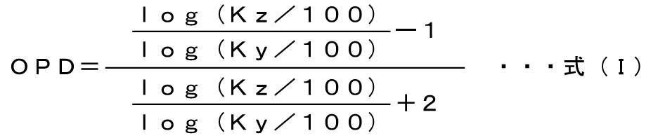
- the degree of the change can be indicated by the value of the order parameter (OPD), preferably 0.50 to 1.00, and more preferably 0.81 to 0.95.
- Ky in the above formula (I) represents the light transmittance when light polarized orthogonal to the axis showing the highest absorption of light in the polarized light emitting element is incident.
- Kz represents the light transmittance when light polarized parallel to the axis showing the highest absorption of light in the polarized light emitting element is incident.
- Polarized light emitting dyes capable of emitting polarized light by utilizing light absorption generally belong to fluorescent dyes or phosphorescent dyes, but specifically, they absorb specific light and utilize the light to emit light energy.
- a dye that can be converted to either a fluorescent dye or a phosphorescent dye may be used, but it is preferable to use a fluorescent dye.
- the dye often has a different wavelength of absorbed light from the emitted light, and is sometimes called a wavelength conversion dye.
- At least one kind of polarized light emitting dye contained in the polarized light emitting element preferably has a fluorescent light emitting characteristic, and in particular, the light in the visible range is polarized by absorbing the light in the ultraviolet region to the near ultraviolet visible region. It is more preferable to have a fluorescent emission characteristic capable of emitting light.
- the polarized light emitting dye has light absorption anisotropy between the axis oriented to the base material and the axis orthogonal to the axis, like the dichroic dye, by orienting the polarized light emitting dye, and the light absorption anisotropy. That is, it exhibits a polarization function.
- the light transmittance (that is, the transmittance on the axis with a small amount of light transmission) was defined as Kz, while the polarized light emitting element in which the polarized light emitting dye was oriented was polarized at an orthogonal position to the axis showing the highest absorption.
- Ky be the light transmittance when light is incident (that is, the transmittance on the axis where the amount of light transmitted is large). Then, by substituting these Ky and Kz into the above equation (I), the order parameter, that is, the degree of orientation order can be calculated.
- the value of the order parameter is generally used as an index used to measure the orientation of substances such as liquid crystals, and the higher the value of the order parameter, the higher the orientation order of the polarized light emitting element. It shows that it is doing.
- the formula for calculating the value of the order parameter is expressed as the following formula (II) (see “Display materials and functional dyes (CMC Publishing, supervised by Hiroyuki Nakazumi, 2004, P65)").
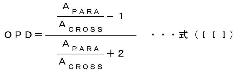
- the following equation (III) is derived.
- the value of the order parameter (OPD) can be expressed by the above equation (I).
- a PARA is the absorbance in the direction parallel to the absorption axis of the oriented polarized luminescent dye
- a CROSS is the absorbance in the direction orthogonal to the absorption axis of the oriented dye. ..
- Each absorbance is calculated by Log (A).
- formula (III) formula (I) is derived by substituting the absorbances obtained by Ky and Kz into the respective absorbances calculated by Log (A). Based on this formula (I), the degree of orientation order of a dye capable of emitting polarized light is controlled by utilizing the absorption of light, whereby a polarized light emitting device exhibiting polarized light emission having a high contrast value can be obtained.
- the upper limit of the value of the order parameter is more preferably set to 0.95.
- the value of the order parameter is preferably controlled in the range of 0.50 to 1.00, more preferably 0.81 to 0.95, and even more preferably 0.85 to 0.94. ..
- a polarized light emitting device exhibiting polarized light emission can be obtained by containing one or a plurality of polarized light emitting dyes in a substrate and orienting them.
- Such a polarized light emitting element exhibits various emission colors by adjusting the blending ratio of the polarized light emitting dye. For example, when the absolute value of hue a * measured according to JIS Z 8781-4: 2013 is 5 or less and the absolute value of hue b * is 5 or less, the emission color from the polarized light emitting element becomes white. Shown.
- the hue a * value and the hue b * value according to the standard of JIS Z 8781-4: 2013 are values generally used as an index indicating the hue of light.
- the polarized luminescent dye is preferably a compound having a stilbene skeleton or a biphenyl skeleton as a basic skeleton, or a salt thereof.
- the polarized light emitting dye having such a basic skeleton is oriented toward the base material so as to exhibit fluorescent light emitting characteristics and to control the value of the order parameter in the range of 0.50 to 1.00. It is possible to emit light having a higher degree of polarization than other polarized light emitting dyes, that is, light having a high contrast.
- the stilbene skeleton and the biphenyl skeleton as the basic skeletons of the polarized luminescent dye have the effect of exhibiting fluorescence emission characteristics in their respective skeletons and exhibiting high dichroism by being oriented toward the substrate. Since this action is due to the structure of each basic skeleton of the stilbene skeleton and the biphenyl skeleton, any substituent may be further bonded to the basic skeleton structure. However, when substituting an azo group for the basic skeletal structure, the substituting position is important in order to obtain a desired amount of emitted light.
- the polarized luminescent dye may be used alone or in combination of two or more.
- the polarized light emitting dye has a fluorescent light emitting characteristic capable of polarized light in the visible range by absorbing light in the ultraviolet region to the near ultraviolet visible region. Specifically, by incorporating a polarized luminescent dye into a substrate and then irradiating light in the ultraviolet to near-ultraviolet visible region, in the visible region (generally 380 to 780 nm), for example, in the wavelength region of 400 to 700 nm.
- ultraviolet light means light in a wavelength range of 400 nm or less, but light in a wavelength range of 430 nm or less is also extremely low in human visual sensitivity. Therefore, the light in the ultraviolet to near-ultraviolet visible region can be defined as the light invisible to the human eye, and for example, the light absorbed by the polarized light emitting dye is preferably the light in the wavelength region of 300 to 430 nm.
- Polarized luminescent dye having a stilbene skeleton is preferably a compound represented by the following formula (1) or a salt thereof.
- L and M each independently have a nitro group, an amino group which may have a substituent, a carbonylamide group which may have a substituent, and a substituent.
- which may be a naphthotriazole group which may have a substituent C 1 -C 20 (1 ⁇ 20 carbon atoms) alkyl group, optionally a vinyl group which may have a substituent and may have a substituent It is selected from the group consisting of an amide group, a ureido group which may have a substituent, an aryl group which may have a substituent, and a carbonyl group which may have a substituent, but is limited thereto. is not.
- the compound having a stilbene skeleton represented by the formula (1) exhibits fluorescence emission, and dichroism can be obtained by orientation. Since the luminescence property is due to the stilbene skeleton, the substituent to which each group of L and M can be bonded is not particularly limited and may be any substituent. It is preferable that the substituent has no azo group.
- Each of the "substituents” is not particularly limited, and examples thereof include the following: Amino group; Nitro group; Cyano group; Hydroxyl group; Sulfonic acid group; Phosphate group; Carboxylic group; Carboxyalkyl groups such as methylcarboxyl group and ethylcarboxyl group; Halogen atoms such as fluorine atom, chlorine atom, bromine atom, iodine atom; Alkoxy groups such as methoxy group, ethoxy group and propoxy group; Aryloxy groups such as phenoxy group and naphthoxy group; Methyl group, ethyl group, n- butyl group, n- hexyl, n- octyl group, n- dodecyl group, an isopropyl group, sec- butyl group, tert- butyl group, a cyclohexyl groups, C 1 -C such cyclopenty
- Aryl groups such as; Methylcarbonyl group, ethylcarbonyl group, n- butyl - C 1 -C 20 alkylcarbonyl group such as a carbonyl group; Arylcarbonyl groups such as phenylcarbonyl group, biphenylcarbonyl group, naphthylcarbonyl group; Methylsulfonyl group, ethylsulfonyl group, propylsulfonyl group, n- butyl - C 1 -C 20 alkylsulfonyl group such as a sulfonyl group; Arylsulfonyl groups such as phenylsulfonyl groups and naphthylsulfonyl groups.
- substituents may have additional substituents, and the above-mentioned examples can be mentioned as the additional substituents.
- the number of such substitution chains is not limited.
- Compound Example 1-5 exemplified later has an amino group as a substituent, the amino group has a triazine group as a substituent, and the triazine group has two amino groups as a substituent and is an amino group.
- Amino groups that may have substituents include, for example: Unsubstituted amino group; Methylamino group, ethylamino group, n-butylamino group, tert-butylamino group, n-hexylamino group, dodecylamino group, dimethylamino group, diethylamino group, di-n-butylamino group, ethylmethylamino group, good C 1 -C 20 alkylamino group which may have a substituent such as ethylhexyl amino group; Arylamino group which may have a substituent such as a phenylamino group, a diphenylamino group, a naphthylamino group, an N-phenyl-N-naphthylamino group; Methylcarbonylamino group, ethylcarbonylamino group, n- butyl - -C C
- an optionally substituted C 1 -C 20 alkyl carbonyl amino group an optionally substituted aryl carbonyl amino group, C 1 -C 20 alkylsulfonylamino group, a substituted group
- the arylsulfonylamino group which may have is preferable.
- Examples of the carbonylamide group that may have a substituent include an N-methyl-carbonylamide group (-CONHCH 3 ), an N-ethyl-carbonylamide group (-CONHC 2 H 5 ), and an N-phenyl-carbonylamide.
- Groups (-CONHC 6 H 5 ) and the like can be mentioned.
- C 1 -C 20 alkyl group which may have a substituent C 1 -C 20 alkyl group, e.g., methyl group, ethyl group, n- butyl group, n- hexyl, n- octyl, n- Linear C 1- C 12 alkyl group such as dodecyl group; branched C 3- C 10 alkyl group such as isopropyl group, sec-butyl group, tert-butyl group; cyclic group such as cyclohexyl group and cyclopentyl group C 3- C 7 alkyl group and the like.
- a linear or branched alkyl group is preferable, and a linear alkyl group is more preferable.
- Examples of the vinyl group which may have a substituent include an ethenyl group, a styryl group, a vinyl group having an alkyl group, a vinyl group having an alkoxy group, a divinyl group, a pentadienyl group and the like.
- Examples of the amide group which may have a substituent include an acetamide group (-NHCOCH 3 ) and a benzamide group (-NHCOC 6 H 5 ).
- the aryl group of the aryl group which may have a substituent, for example, a phenyl group, a naphthyl group, an anthracenyl group, a biphenyl group and the like, preferably a C 6 -C 12 aryl group.
- the aryl group may be a 5- or 6-membered heterocyclic group containing 1 to 3 heteroatoms selected from the group consisting of a nitrogen atom, an oxygen atom and a sulfur atom as ring-constituting atoms.
- the heterocyclic group contains an atom selected from a nitrogen atom and a sulfur atom as a ring-constituting atom.
- Examples of the carbonyl group which may have a substituent include a methylcarbonyl group, an ethylcarbonyl group, an n-butyl-carbonyl group, a phenylcarbonyl group and the like.
- Examples of the compound represented by the formula (1) include the Kayaphor series (manufactured by Nippon Kayaku Co., Ltd.), the Whitex series (manufactured by Sumitomo Chemical Co., Ltd.) such as Whitex RP, and the like, which are also represented by the formula (1) below. Examples of, but are not limited to, these compounds.
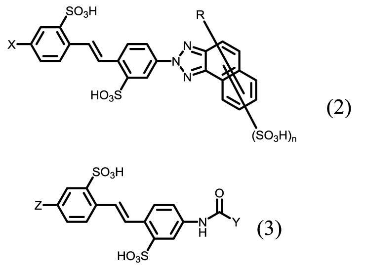
- a compound represented by the following formula (2) or formula (3) or a salt thereof is preferable.
- a polarized light emitting device that emits clear white light can be obtained.
- the compounds represented by the following formulas (2) and (3) also exhibit fluorescence emission due to the stilbene skeleton, and dichroism can be obtained by orientation.
- X represents an amino group which may have a nitro group or a substituent.
- the amino group which may have a substituent is defined in the same manner as the amino group which may have a substituent in the above formula (1).
- X is a nitro group, an optionally substituted C 1 -C 20 alkyl carbonyl amino group, an optionally substituted aryl carbonyl amino group, C 1 -C 20 alkylsulfonylamino group , Or an arylsulfonylamino group which may have a substituent, and more preferably a nitro group.
- R is a halogen atom such as a hydrogen atom, a chlorine atom, a bromine atom or a fluorine atom, a hydroxyl group, a carboxyl group, a nitro group, an alkyl group which may have a substituent, or a substituent.
- the alkyl group which may have a substituent group is similarly defined with good C 1 -C 20 alkyl group which may have a substituent in the formula (1).
- the alkoxy group which may have a substituent is preferably a methoxy group, an ethoxy group or the like.
- the amino group which may have a substituent is defined in the same manner as the amino group which may have a substituent in the above formula (1), and is preferably a methylamino group, a dimethylamino group, an ethylamino group or a diethylamino group. , Or a phenylamino group or the like.
- R is preferably a hydrogen atom or a C 1 -C 20 alkyl group, when R is C 1 -C 20 alkyl group, preferably a methyl group.
- R may be bonded to any carbon of the naphthalene ring in the naphthotriazole ring, but when the carbon atom condensed with the triazole ring is at the 1-position and the 2-position, the 3-position, 5-position, or 8 is used. It is preferably bonded to the position.
- n is an integer of 0 to 3, preferably 1.
- ⁇ (SO 3 H) may be bonded to an arbitrary carbon atom of the naphthalene ring in the naphthotriazole ring.
- R is a hydrogen atom and n is 1 or 2.
- Y represents an optionally substituted C 1 -C 20 alkyl group, optionally a vinyl group which may have a substituent, or an aryl group which may have a substituent.
- an aryl group which may have a substituent is preferable, a naphthyl group which may have a substituent is more preferable, and a naphthyl group in which an amino group and a sulfo group are substituted as a substituent is preferable. Is particularly preferable.
- Z is defined in the same manner as X in the above formula (2), represents a nitro group or an amino group which may have a substituent, and is preferably a nitro group.
- the compound having a biphenyl skeleton is preferably a compound represented by the following formula (4) or a salt thereof.
- P and Q may independently have a nitro group, an amino group which may have a substituent, a carbonylamide group which may have a substituent, and a substituent.
- naphthotriazole group which may have a substituent C 1 -C 20 alkyl group, an optionally substituted vinyl group, an amide group which may have a substituent and may have a substituent It represents a ureido group, an aryl group which may have a substituent, or a carbonyl group which may have a substituent, but is not limited thereto.
- P and / or Q preferably do not have an azo group in order to increase the fluorescence emission of the compound having a biphenyl skeleton.
- the compound represented by the above formula (4) is preferably a compound represented by the following formula (5).
- j independently represents an integer of 0 to 2.
- R 1 , R 2 , R 3 and R 4 are independently hydrogen atom, C 1- C 4 alkyl group, C 1- C 4 alkoxy group, aralkylyl group, alkeniroxy group, C 1 -C 4 alkyl sulfonyl group, C 6- C 20 aryl sulfonyl group, carboxylic amide group, sulfon amide group, carboxyalkyl group.
- the position where R 1 to R 4 are bonded is not particularly limited, but when the carbon atom bonded to the vinyl group is the 1-position, the 2-position, 4-position, and 6-position are preferable, and the 4-position is preferable. Is particularly preferable.
- the C 1 -C 4 alkyl group e.g., methyl group, ethyl group, propyl group, n- butyl group, sec- butyl group, tert- butyl group, a cyclobutyl group.
- the C 1 -C 4 alkoxy group include a methoxy group, an ethoxy group, a propoxy group, n- butoxy group, sec- butoxy group, tert- butoxy group, cyclobutoxy group, and the like.
- Examples of the aralkyloxy group include C 7- C 18 aralkyloxy groups.
- the alkenyloxy group for example, C 1 -C 18 alkenyloxy group.
- the C 1 -C 4 alkylsulfonyl group for example, include methylsulfonyl group, ethylsulfonyl group, propylsulfonyl group, n- butylsulfonyl group, sec- butylsulfonyl group, tert- butylsulfonyl group, cyclobutylsulfonyl group, and the Be done.
- the compound represented by the above formula (5) can be prepared by a known method, and can be synthesized, for example, by condensing 4-nitrobenzaldehyde-2-sulfonic acid with phosphonate and then reducing the nitro group. ..
- Specific examples of the compound represented by the formula (5) include the following compounds described in JP-A-4-226162.
- the salt of the compound represented by the formulas (1) to (5) means a state in which the free acid of each compound represented by each of the above formulas forms a salt together with an inorganic cation or an organic cation.
- the inorganic cations for example, the cations of alkali metals (such as lithium, sodium, potassium, etc.), or ammonium (NH 4 +), and the like.
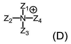
- examples of the organic cation include organic ammonium represented by the following formula (D).
- Z 1 to Z 4 independently represent a hydrogen atom, an alkyl group, a hydroxyalkyl group or a hydroxyalkoxyalkyl group, and at least one of Z 1 to Z 4 is hydrogen. It is a group other than an atom.
- Z 1 to Z 4 include: Methyl, ethyl, butyl group, pentyl group, C 1 -C 6 alkyl such as hexyl, preferably C 1 -C 4 alkyl group; Hydroxy C 1- C 6 alkyl groups such as hydroxymethyl group, 2-hydroxyethyl group, 3-hydroxypropyl group, 2-hydroxypropyl group, 4-hydroxybutyl group, 3-hydroxybutyl group and 2-hydroxybutyl are preferable.
- hydroxy C 1- C 4 alkyl group Is a hydroxy C 1- C 4 alkyl group;
- hydroxy C 1- C 6 alkoxy C 1- C 6 alkyl groups such as hydroxyethoxymethyl group, 2-hydroxyethoxyethyl group, 3-hydroxyethoxypropyl group, 3-hydroxyethoxybutyl group and 2-hydroxyethoxybutyl group,
- a hydroxy C 1- C 4 alkoxy C 1- C 4 alkyl group is preferred.
- each cation such as lithium, sodium, potassium, monoethanolamine, diethanolamine, triethanolamine, monoisopropanolamine, diisopropanolamine, triisopropanolamine, and ammonium is more preferable.
- Each inorganic cation of lithium, ammonium or sodium is particularly preferred.
- the polarized light emitting dye having the above structure does not have an azo group in the molecule, the absorption of light due to the azo bond is suppressed.
- a compound having a stilbene skeleton exhibits a luminescent effect when irradiated with ultraviolet light, and the molecule is stabilized by the presence of a strong carbon-carbon double bond in the stilbene skeleton. Therefore, a polarized light emitting element using a polarized light emitting dye having such a specific structure can absorb light and utilize the energy to emit polarized light in the visible region.
- the polarized light emitting element exhibiting the above-mentioned characteristics may further contain at least one kind of fluorescent dye and / or organic dye different from the above-mentioned polarized light emitting dye as long as the polarization performance of the polarized light emitting element is not impaired.
- the fluorescent dye used in combination include C.I. I. Fluorescent Fluorescenter 5, C.I. I. Fluorescent Fluorescenter 8, C.I. I. Fluorescent Fluorescent 12, C.I. I. Fluorescent Fluorescent 28, C.I. I. Fluorescent Brightener 30, C.I. I. Fluorescent Fluorescent 33, C.I. I. Fluorescent Fluorescent 350, C.I. I. Fluorescent Fluorescent 360, C.I. I. Fluorescent Fluorescent 365 and the like can be mentioned.
- organic dye for example, C.I. Ai. direct. Yellow 12, Sea. Ai. direct. Yellow 28, Sea. Ai. direct. Yellow 44, Sea. Ai. direct. Orange 26, Sea. Ai. direct. Orange 39, Sea. Ai. direct. Orange 71, Sea. Ai. direct. Orange 107, Sea. Ai. direct. Red 2, Sea. Ai. direct. Red 31, Sea. Ai. direct. Red 79, Sea. Ai. direct. Red 81, Sea. Ai. direct. Red 247, Sea. Ai. direct. Blue 69, Sea. Ai. direct. Blue 78, Sea. Ai. direct. Green 80 and Sea. Ai. direct. Green 59 and the like can be mentioned.
- These organic dyes may be free acids, or may be alkali metal salts (eg Li salt, Na salt, K salt), ammonium salts or amine salts.
- the polarized light emitting device is obtained by orienting the polarized light emitting dye.
- the method of orientation is not limited, and examples thereof include a method of aligning the polarized light emitting dye by containing the polarized light emitting dye in the base material and aligning the entire base material.
- the substrate used in the present invention is not particularly limited as long as it can contain a polarized light emitting dye and can be oriented.
- Such a base material preferably contains, for example, a hydrophilic polymer that adsorbs a polarized luminescent dye and can be crosslinked with a boron derivative or the like, and is hydrophilic obtained by forming a film of the hydrophilic polymer. Polymer films are more preferred.
- the hydrophilic polymer is not particularly limited, but for example, a polyvinyl alcohol-based resin and a starch-based resin are preferable.
- the hydrophilic polymer preferably contains a polyvinyl alcohol-based resin or a derivative thereof from the viewpoint of dyeability, processability, crosslinkability and the like of the polarized light emitting dye, and more preferably contains polyvinyl alcohol.
- the polyvinyl alcohol-based resin or its derivative include polyvinyl alcohol or a derivative thereof, polyvinyl alcohol or a derivative thereof as an olefin such as ethylene or propylene, or crotonic acid, acrylic acid, methacrylic acid, and maleic acid.
- the base material is preferably a film made of polyvinyl alcohol or a partially esterified polyvinyl alcohol derivative.
- a method for producing the polarized light emitting device of the present invention using a base material containing a polyvinyl alcohol-based resin will be exemplified.
- the base material containing the polyvinyl alcohol-based resin for example, a commercially available product may be used, or it may be produced by forming a film of the polyvinyl alcohol-based resin.
- the film-forming method of the polyvinyl alcohol-based resin is not particularly limited, and for example, a method of melt-extruding a hydrous polyvinyl alcohol, a casting film-forming method, a wet film-forming method, and a gel film-forming method (the polyvinyl alcohol aqueous solution is once cooled).
- a known film-forming method can be adopted, such as a method of extracting and removing the solvent after gelation), a cast film-forming method (flowing a polyvinyl alcohol aqueous solution on a substrate and drying), and a method using a combination thereof.
- the thickness of the base material can be appropriately designed, but is usually 10 to 100 ⁇ m, preferably 20 to 80 ⁇ m.
- a swelling treatment may be performed in order to facilitate the adsorption of the polarized light emitting dye.
- the swelling treatment is preferably carried out by immersing the base material in a swelling solution at 20 to 50 ° C. for 30 seconds to 10 minutes, and the swelling solution is preferably water.
- the draw ratio of the base material with the swelling liquid is preferably adjusted to 1.00 to 1.50 times, more preferably 1.10 to 1.35 times.
- At least one kind of polarized luminescent dye is impregnated and adsorbed on the base material obtained by performing the swelling treatment in the above swelling step.
- the dyeing step is not particularly limited as long as it is a method of impregnating and adsorbing the polarized light emitting dye on the base material, but for example, a method of immersing the base material in a dyeing solution containing the polarized light emitting dye, the same as the base material. Examples thereof include a method of applying a dyeing solution and adsorbing it. Of these, a method of immersing in a dyeing solution containing a polarized luminescent dye is preferable.
- the concentration of the polarized luminescent dye in the dyeing solution is not particularly limited as long as the polarized luminescent dye is sufficiently adsorbed in the substrate, but is, for example, 0.0001 to 1% by mass in the dyeing solution. It is preferably 0.001 to 0.5% by mass, and more preferably 0.001 to 0.5% by mass.
- the temperature of the dyeing solution in the dyeing step is preferably 5 to 80 ° C, more preferably 20 to 50 ° C, and particularly preferably 40 to 50 ° C.
- the time for immersing the substrate in the dyeing solution is important in controlling the value of the order parameter exhibited by the polarizing light emitting device. In order to control the value of the order parameter within a desired range, the time for immersing the substrate in the dyeing solution is preferably adjusted between 6 and 20 minutes, more preferably between 7 and 10 minutes.
- the polarized luminescent dye contained in the dyeing solution may be used alone or in combination of two or more. Since the luminescent color of the polarized luminescent dye differs depending on the compound, it is possible to appropriately adjust the luminescent color to be produced by containing one or more kinds of the polarized luminescent dye in the substrate. Further, if necessary, the dyeing solution may further contain one or more organic dyes and / or fluorescent dyes different from the polarized light emitting dyes.
- the blending ratio of the fluorescent dye or the organic dye is not particularly limited, but in general, the total amount of the fluorescent dye and / or the organic dye is 0.01 to 10 parts by mass with respect to 100 parts by mass of the polarizing element. It is preferable to use in the range of.
- a dyeing aid may be further used if necessary.
- the dyeing aid include sodium carbonate, sodium hydrogencarbonate, sodium chloride, sodium sulfate (Glauber's salt), anhydrous sodium sulfate, sodium tripolyphosphate and the like, and sodium sulfate is preferable.
- the content of the dyeing aid can be arbitrarily adjusted by the above-mentioned immersion time based on the dyeability of the dichroic dye used, the temperature at the time of dyeing, etc., but is 0.0001 to 10% by mass in the dyeing solution. It is preferably 0.0001 to 2% by mass, and more preferably 0.0001 to 2% by mass.
- a pre-cleaning step can be optionally performed in order to remove the dyeing solution adhering to the surface of the base material in the dyeing step.
- a pre-cleaning step it is possible to suppress the transfer of the polarized luminescent dye remaining on the surface of the substrate into the liquid to be treated next.
- water is generally used as the cleaning liquid.
- cleaning method it is preferable to immerse the dyed base material in the cleaning liquid, and on the other hand, cleaning can also be performed by applying the cleaning liquid to the base material.
- the washing time is not particularly limited, but is preferably 1 to 300 seconds, and more preferably 1 to 60 seconds.
- the temperature of the cleaning liquid in this pre-cleaning step needs to be a temperature at which the material constituting the base material does not dissolve, and the cleaning treatment is generally performed at 5 to 40 ° C. Even if there is no pre-cleaning step, the pre-cleaning step can be omitted because it does not have a particularly large effect on the performance of the polarizing element.
- the substrate can contain a cross-linking agent.
- a cross-linking agent for example, a solution containing a boron compound is used.
- the boron compound examples include inorganic compounds such as boric acid, borax, boron oxide and boron hydroxide, alkenylboronic acid, arylboronic acid, alkylboronic acid, boronic acid ester, trifluoroborate or a salt thereof, which are boronic acids.
- Boric acid and borax are preferable, and boric acid is particularly preferable.
- the solvent in the treatment solution is not particularly limited, but water is preferable.
- the concentration of the boron derivative in the treatment solution is preferably 0.1 to 15% by mass, more preferably 0.1 to 10% by mass.
- the temperature of the treatment solution is preferably 30 to 80 ° C, more preferably 40 to 75 ° C.
- the treatment time of this cross-linking step is preferably 30 seconds to 10 minutes, more preferably 1 to 6 minutes.
- the polarized light emitting device obtained by this cross-linking step exhibits high contrast. This is an excellent action that cannot be expected from the function of the boron compound used for the purpose of improving water resistance or light transmission in the prior art.
- a fixing treatment may be further performed with an aqueous solution containing a cation and a cationic polymer compound.
- the cation is an ion derived from a metal such as sodium, potassium, calcium, magnesium, aluminum, iron or barium, and a divalent ion is preferably used.
- cationic polymer compound for example, dicyanamide and formalin polymerization condensate as dicyan, dicyandiamide / diethylenetriamine polycondensate as polyamine, epichlorohydrin / dimethylamine addition polymer as polycation, dimethyldialylammon Nium chloride / ion dioxide ion copolymer, diallylamine salt polymer, dimethyldiallylammonium chloride polymer, allylamine salt polymer, dialkylaminoethyl acrylate quaternary salt polymer and the like are used.
- the stretching step is performed by uniaxially stretching the base material in a certain direction.
- the stretching method may be either a wet stretching method or a dry stretching method.
- the draw ratio of the substrate is also important in controlling the values of the order parameters.
- the draw ratio of the base material is preferably 3.3 times or more, and more preferably 3.3 to 8.0 times. , 3.5 to 6.0 times is more preferable, and 4.0 to 5.0 times is particularly preferable.
- the stretching treatment is performed while immersing the base material in a solution containing at least one cross-linking agent.
- a cross-linking agent for example, a boron compound in the above-mentioned cross-linking step can be used, and preferably, the stretching treatment can be performed in the treatment solution used in the cross-linking step.
- the stretching temperature is preferably 40 to 60 ° C, more preferably 45 to 58 ° C.
- the stretching time is usually 30 seconds to 20 minutes, preferably 2 to 7 minutes.
- the wet stretching step may be carried out by one-step stretching or by two or more steps of multi-step stretching.
- the stretching treatment may be optionally performed before the dyeing step, and in this case, the orientation of the polarized light emitting dye can also be performed at the time of dyeing.
- the stretching medium when the stretching medium is an air medium, it is preferable to stretch the base material at a temperature of the air medium of room temperature to 180 ° C.
- the humidity is preferably in an atmosphere of 20 to 95% RH.
- the method for heating the base material include, but are not limited to, an inter-roll zone stretching method, a roll heating stretching method, a hot pressure stretching method, and an infrared heating stretching method.
- the dry stretching step may be carried out by one-step stretching or by two or more steps of multi-step stretching.
- the base material containing the polarized light emitting dye can be stretched while containing the boron derivative, or the base material can be stretched after containing the boron compound, but the base material contains the boron compound.
- the temperature at which the boron derivative is applied is preferably 40 to 90 ° C, more preferably 50 to 75 ° C.
- the concentration of the boron compound is preferably 1 to 10%, more preferably 3 to 8%.
- the treatment time for dry stretching is preferably 1 to 15 minutes, more preferably 2 to 12 minutes, and even more preferably 3 to 10 minutes.
- the cross-linking agent may precipitate or foreign matter may adhere to the surface of the base material, so that the cleaning step of cleaning the surface of the base material can be performed.
- the washing time is preferably 1 second to 5 minutes.
- a cleaning method it is preferable to immerse the base material in a cleaning liquid, and on the other hand, the cleaning liquid can be applied to the base material or cleaned by coating. Water is preferable as the cleaning liquid.
- the cleaning treatment may be carried out in one step or in two or more steps.
- the temperature of the cleaning liquid in the cleaning step is not particularly limited, but is usually 5 to 50 ° C, preferably 10 to 40 ° C, and may be room temperature.
- examples of the solvent for the solution or treatment solution used in each of the above steps include dimethyl sulfoxide; N-methylpyrrolidone; methanol, ethanol, propanol, isopropyl alcohol, glycerin, ethylene glycol, propylene glycol, and diethylene glycol. Alcohols such as triethylene glycol, tetraethylene glycol or trimethylolpropane; amines such as ethylenediamine and diethylenetriamine can be mentioned.
- the solvent of the solution or the treatment liquid is not limited to these, but is preferably water. Further, the solvent of these solutions or the treatment liquid may be used alone or in combination of two or more.
- a drying step of the base material is performed.
- the drying treatment can be carried out by natural drying, in order to further improve the drying efficiency, it can be carried out by compression with a roll, removal of moisture on the surface with an air knife or a water absorption roll, etc. It is also possible to do it.
- the temperature of the drying treatment is preferably 20 to 100 ° C, more preferably 60 to 100 ° C.
- the drying time is preferably 30 seconds to 20 minutes, more preferably 5 to 10 minutes.
- the polarized light emitting device according to the present invention can be manufactured by the above-mentioned manufacturing method, and the obtained polarized light emitting device exhibits polarized light emission having high durability and high degree of polarization (contrast).
- a polyvinyl alcohol-based resin film containing a polarized light emitting dye is prepared in advance, and each step of swelling, stretching, washing, cross-linking, and drying is performed without going through a dyeing step to carry out polarized light emission of the present invention. It is also possible to manufacture the element.
- the polarized light emitting device according to the present invention can be manufactured by the above-exemplified manufacturing method, and the obtained polarized light emitting device exhibits polarized light emission having high durability and high degree of polarization (contrast).
- the polarized light emitting element uses the energy obtained by absorbing light, particularly light in the ultraviolet region, to emit polarized light in the visible region.
- the polarized light emission has a high degree of polarization (contrast). Since the light emitted from the polarized light emitting element is polarized in the visible region, when the polarized light emitting element is observed through a general polarizing plate having a polarizing function for the light in the visible region, the axis of the polarizing plate By changing the angle, polarized light emission and non-polarized light emission can be visually recognized.
- the degree of polarization of the polarized light emitted by the polarized light emitting element is, for example, 70% or more, preferably 80% or more, more preferably 90% or more, still more preferably 95% or more, and particularly preferably 99% or more. Further, the higher the contrast, the more preferable, and the higher the degree of polarization, the higher the tendency.
- the transmittance of the light in the visible region of the polarized light emitting element is, for example, 60% or more, preferably 70% or more in terms of the luminosity correction transmittance. , More preferably 80% or more, still more preferably 85% or more, and particularly preferably 90% or more. Since such a polarized light emitting element has a high degree of polarization, the absorption of light in the visible region becomes small in a non-light emitting state, whereby a highly transparent polarized light emitting element can be obtained.
- the optical element of the present invention can be obtained by laminating the polarized light emitting element and the non-light emitting polarizing element thus obtained.
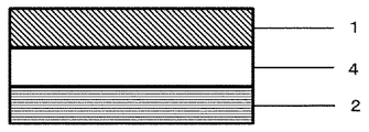
- FIG. 1 shows an optical element 3 of the present invention in which a polarized light emitting element 1 and a non-light emitting polarizing element 2 are laminated.
- the non-emission polarizing element 2 is an absorption type polarizing element, it is preferable to stack the polarization axis of the absorption type polarizing element and the emission polarization axis of the polarization light emitting element 1 so as to be orthogonal to each other.
- the absorption axis of the absorption type polarizing element and the emission polarization axis of the polarizing light emitting element are laminated so as to be parallel to each other.
- the non-emission polarizing element 2 is a reflection type polarizing element
- the reflection polarization axis of the reflection type polarizing element and the emission polarization axis of the polarization light emitting element are laminated so as to be parallel to each other.
- the adhesive layer is omitted in FIGS.
- various adhesive means such as an adhesive, an adhesive, and a plasma bonding treatment can be used for laminating.
- the adhesive include a water-soluble adhesive obtained by adding a cross-linking agent such as glioxal to an aqueous solution of polyvinyl alcohol or modified polyvinyl alcohol, or an epoxy-based, urethane-based, or acrylic-based heat-curable urethane.
- heat-curable adhesives such as system adhesives and ultraviolet curable adhesives containing an ultraviolet curable resin and a photopolymerization initiator, but in particular, if light can be transmitted and a desired adhesive force can be obtained. There is no limit.
- the pressure-sensitive adhesive examples include an acrylic pressure-sensitive adhesive obtained by cross-linking an acrylic polymer made of a copolymer of acrylic acid or a plurality of acrylic acid esters with a curing agent such as isocyanate, and a silicone pressure-sensitive adhesive made of a silicone resin. Can be mentioned. Further, a plasma bonding treatment may be used in which the surface of the polarizing element is activated by atmospheric pressure plasma treatment in an inert gas, and then laminated and bonded.
- a support 4 may be interposed between them.
- the base material is not particularly limited as long as it is transparent enough to transmit light, but it is preferably as transparent as possible if it is not intentionally colored from the viewpoint of color tone and design, and visible light at 400 nm to 700 nm.
- the transmittance is 80% to 100%, more preferably 85% to 98%, and even more preferably 90% to 95%.
- the material of the support is not particularly limited, and examples thereof include glass and resin.
- the resin for example, various resins such as cellulose resin such as triacetyl cellulose, acrylic resin, nylon resin, and polyolefin resin can be used.
- This support may be used in one layer or two or more layers. Further, this support may be attached to each or any of the non-emission polarizing element and the polarized light emitting element with an adhesive, an adhesive or the like, and if there is practically sufficient adhesion to the polarizing element, an adhesive It may be directly laminated without the intervention of.
- the adhesive or the adhesive is not particularly limited, but it is preferable to use a water-soluble adhesive, a thermosetting adhesive, an ultraviolet curable adhesive, an acrylic adhesive, or the like.
- a support may be provided on one side of the optical element, or both sides of the optical element may be sandwiched between the supports.
- the means for providing or holding the support is not particularly limited, but when an adhesive or an adhesive is used, a water-soluble adhesive, a thermosetting adhesive, an ultraviolet curable adhesive, an acrylic adhesive, or the like is used. Is preferable.
- various resin materials such as glass, cellulose resin such as triacetyl cellulose, acrylic resin, nylon resin, and polyolefin resin can be used.
- the transmittance of the base material or the adhesive layer at the wavelength of the light absorbed by the element is preferably 50 so as not to interfere with the light emission of the polarized light emitting element. It is preferably about 100%, more preferably 70 to 98%, and even more preferably about 80 to 95%.
- the support in the present invention preferably does not absorb light having an absorption wavelength of the polarized light emitting element. For example, since the support often contains an ultraviolet absorber, it is preferable to use a support that does not contain an ultraviolet absorber in the case of ultraviolet rays having an absorption wavelength of 350 to 380 nm of the polarizing light emitting element. FIG.
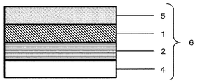
- FIG. 3 shows the polarizing plate 6 of the present invention in which the optical element 3 of the present invention is sandwiched between the support 4 and the support 5 that transmits light having a wavelength required for polarized light emission.
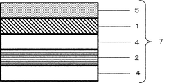
- a support 4 exists between the polarized light emitting element 1 and the non-light emitting polarizing element 2, and the polarizing plate 7 of the present invention is configured by sandwiching them between the support 4 and the support 5. It may be.
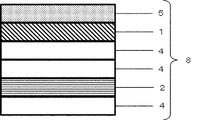
- the polarizing light emitting element 1 is sandwiched between the supports 4 and 5, while the non-light emitting polarizing element 2 is sandwiched between the supports 4 and 5, and the polarizing plate 8 of the present invention is configured by laminating each of them. May be good.
- a support is adhered to one side of the non-emission polarizing element produced as described above and the emission polarizing element. Use and stick together. Next, they may be attached to each other by using an adhesive or the like so that the polarizing elements face each other.
- the eyewear lens of the present invention can be obtained by processing a lens using the polarizing plate of the present invention obtained by sandwiching the optical element of the present invention thus obtained.
- the lens for eyewear of the present invention refers to an article including a state in which the polarizing plate of the present invention is bent into a lens shape.
- FIG. 6 shows the eyewear lens 9 of the present invention obtained by bending the polarizing plate 6 of the present invention.
- the polarizing plate of the present invention is processed into a desired curved surface shape using a bending machine, and further cut into a desired shape.
- the eyewear lens of the present invention needs to be arranged so that the polarized light emitting element side is finally convex.
- FIG. 7 shows one form of the eyewear lens 11 of the present invention processed into a lens shape as described above using such an insert molding resin 10 (hard coat and antifouling treatment layer are omitted).
- the eyewear of the present invention can be obtained by attaching the eyewear lens of the present invention to the frame of sunglasses or goggles.
- Example 1 Manufacturing of polarized light emitting element
- a polyvinyl alcohol film having a thickness of 75 ⁇ m (VF-PS # 7500 manufactured by Kuraray Co., Ltd.) was immersed in warm water at 40 ° C. for 3 minutes to swell the film.
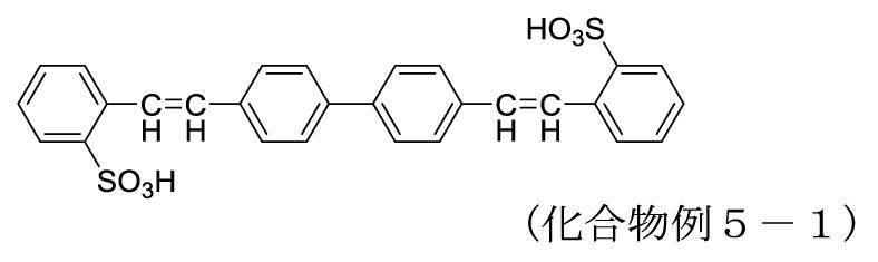
- the film obtained by swelling was subjected to 0.05 part of an aqueous solution of 4,4'-bis- (sulfostylyl) biphenyl disodium (Tinopal NFW Liquid manufactured by BASF) described in Compound Example 5-1 and 1.0 part of Glauber's salt.
- the film was immersed in an aqueous solution at 45 ° C. containing 1000 parts of water for 10 minutes.
- the obtained film was immersed in a 3% aqueous boric acid solution at 50 ° C. for 5 minutes and stretched 5.0 times.
- the film obtained by stretching was washed with water at room temperature for 20 seconds while maintaining a tense state, and dried to obtain a polarized light emitting device.
- the obtained polarized light emitting element was measured using a spectrophotometer (manufactured by Hitachi, Ltd .: U-4100), the absorption peak was 370 nm, the luminosity factor correction single transmittance (Ys) was 92.3%, and the order parameter was The value of (OPD) was 0.886.
- both sides of a triacetyl cellulose film (ZRD-60 manufactured by Fuji Film Co., Ltd.) that transmits ultraviolet rays having a transmittance of 90% at 370 nm are used at 35 ° C. using a 1.5-specified aqueous sodium hydroxide solution. It was treated for minutes, washed with water, and then dried at 70 ° C. for 10 minutes.
- a triacetyl cellulose film treated with sodium hydroxide was laminated on one side of the polarized light emitting element produced above via an aqueous solution containing a 4% polyvinyl alcohol resin (NH-26 manufactured by Nippon Vinegar Vipovar) to obtain a polarizing element.
- a protective film (NSA-33T manufactured by Sanei Kaken Co., Ltd.) was attached to the other surface and dried at 60 ° C. for 10 minutes to obtain a polarized light emitting element having a triacetyl cellulose film that transmits ultraviolet rays on one side.
- the sandwiched polarizing plate 6 of the present invention was obtained.
- the polarizing plate of the present invention was obtained by laminating with each other.
- Example 1 Evaluation of Example 1
- the polarized light emitting layer showed pale light emission.
- the surroundings were observed from the absorption type polarizing element side so that the absorption axis of the polarizing element was horizontal to the ground, but no glare was felt (a unified view by 10 monitors).
- the polarizing light emitting element is arranged so as to be on the water surface side, the polarization light emitting axis is substantially parallel to the water surface, and the absorption type polarizing element is transmitted.
- the polarized light emitting element When the water surface was observed at a position where the axes were orthogonal (the absorption axis was parallel to the light emitting axis of the polarized light emitting element), the polarized light emitting element emitted strong light, but when the water surface was observed from the absorption type polarizer side, it was dazzling. It was not felt, and the reflection on the water surface was greatly reduced, and the visibility was good (unified view by 10 monitors).
- Example 2 Evaluation of Example 2
- the polarizing plate of the present invention When the polarizing plate of the present invention was evaluated in the same manner as in Example 1, it showed stronger light emission than in Example 1. In this state, the surroundings were observed from the reflective polarizer side so that the reflecting axis of the polarizer was horizontal to the ground, but no glare was felt (a unified view by 10 monitors). Further, in a place where the reflected light of sunlight from the water surface is strong, the polarized light emitting element is arranged so as to be on the water surface side, the polarization light emitting axis is substantially parallel to the water surface, and the light emitting polarizing element is transmitted.
- the polarized light emitting element When the water surface was observed at a position where the axes were orthogonal (the reflection axis was parallel to the light emitting axis of the polarized light emitting element), the polarized light emitting element emitted strong light, but when the water surface was observed from the reflective polarizer side, it was dazzling. It was not felt, and the reflection on the water surface was greatly reduced, and the visibility was good (a unified view by 10 monitors).
- the polarized light emitting layer showed pale light emission when sunlight in fine weather was applied to the polarized light emitting element side.
- the surroundings were observed from the side of the colored triacetyl cellulose film in this state, it felt dazzling (a unified view by 10 monitors).
- the polarized light emitting element is arranged so as to be on the water surface side, and the polarized light emitting axis is further arranged so as to be substantially parallel to the water surface. The water surface was observed from the cellulose film side, but it felt dazzling and the visibility was not good (a unified view by 10 monitors).
- the intensity of ultraviolet rays outdoors can be estimated by the degree of light emission, and it can be used as an index for determining whether or not to wear sunglasses.
- the polarized light emitting element can be made to emit light by the light in the ultraviolet region to the near-ultraviolet visible region contained in the external light, and it is possible to impart unprecedented design.
- the emitted light is polarized, the emitted light is reflected and / or absorbed by the laminated non-emission polarizing elements. Therefore, the function as polarized sunglasses can be maintained.
- Polarized light emitting element 2 Non-emission polarizing element 3: Optical element of the present invention 4: Support 5: Support that transmits light of a wavelength required for polarized light emission 6: Polarizing plate of the present invention 7: Polarized light of the present invention Plate 8: Polarizing plate 9 of the present invention: Eyewear lens 10 of the present invention: Injection resin 11: Eyewear lens 12 of the present invention: Colored triacetyl cellulose film 13: Laminate
Landscapes
- Physics & Mathematics (AREA)
- Health & Medical Sciences (AREA)
- Ophthalmology & Optometry (AREA)
- General Physics & Mathematics (AREA)
- Optics & Photonics (AREA)
- General Health & Medical Sciences (AREA)
- Spectroscopy & Molecular Physics (AREA)
- Polarising Elements (AREA)
- Electroluminescent Light Sources (AREA)
- Eyeglasses (AREA)
Abstract
Description
[発明1]
可視域の光を偏光発光する偏光発光素子と可視域の光を吸収及び/又は反射する非発光偏光素子とを積層したことを特徴とする光学素子。
[発明2]
偏光発光素子の発光偏光軸と非発光偏光素子の偏光軸とが直交していることを特徴とする発明1に記載の光学素子。
[発明3]
偏光発光素子と非発光偏光素子とが接着層を介して積層されていることを特徴とする発明1又は2に記載の光学素子。
[発明4]
偏光発光素子と非発光偏光素子とが支持体を介して積層されていることを特徴とする発明1~3のいずれか一項に記載の光学素子。
[発明5]
発明1~4のいずれか一項に記載の光学素子の少なくとも片側に基材を備えていることを特徴とする偏光板。
[発明6]
偏光発光素子側に備えられた基材において、偏光発光に必要な光の波長の透過率が50%以上であることを特徴とする発明5に記載の偏光板。
[発明7]
発明1~4のいずれか一項に記載の光学素子又は発明5もしくは6に記載の偏光板を備え、かつ、偏光発光素子が外側になるよう配置されたことを特徴とするアイウェア用レンズ。
[発明8]
発明7に記載のアイウェアレンズを備えたアイウェア。
吸収型偏光素子が一部の可視光の偏光を反射してもよく、反射型偏光素子が一部の可視光の偏光を吸収してもよい。

偏光発光色素は、スチルベン骨格又はビフェニル骨格を基本骨格として有する化合物又はその塩であることが好ましい。このような基本骨格を有する偏光発光色素が、蛍光発光特性を示しつつ、かつ、オーダーパラメーターの値が0.50~1.00の範囲に制御されるよう基材に配向されるにことにより、他の偏光発光色素よりも高い偏光度を有する光、すなわち、高いコントラストを有する光を発光させることができる。偏光発光色素の基本骨格としてのスチルベン骨格及びビフェニル骨格は、それぞれの骨格自体が蛍光発光特性を示し、かつ、基材に配向させることにより高い二色性を示す作用を有する。この作用は、スチルベン骨格及びビフェニル骨格の各基本骨格の構造に起因するため、基本骨格構造にはさらに任意の置換基が結合されていてもよい。ただし、基本骨格構造にアゾ基を置換する場合、所望とする発光光量が得るためにはその置換位置が重要となる。偏光発光色素は、1種単独で使用してもよく、2種以上組み合わせて併用してもよい。
スチルベン骨格を有する偏光発光色素は、好ましくは、下記式(1)で表される化合物又はその塩である。

アミノ基;
ニトロ基;
シアノ基;
ヒドロキシル基;
スルホン酸基;
リン酸基;
カルボキシル基;
メチルカルボキシル基、エチルカルボキシル基等カルボキシアルキル基;
フッ素原子、塩素原子、臭素原子、ヨウ素原子等のハロゲン原子;
メトキシ基、エトキシ基、プロポキシ基等のアルコキシ基;
フェノキシ基、ナフトキシ基等アリールオキシ基;
メチル基、エチル基、n-ブチル基、n-ヘキシル基、n-オクチル基、n-ドデシル基、イソプロピル基、sec-ブチル基、tert-ブチル基、シクロヘキシル基、シクロペンチル基等のC1-C20アルキル基;
フェニル基、ナフチル基、アントラセニル基、ビフェニル基、環構成原子として窒素原子、酸素原子及び硫黄原子からなる群から選択される1~3つのヘテロ原子を含む5員環又は6員環の複素環基等のアリール基;
メチルカルボニル基、エチルカルボニル基、n-ブチル-カルボニル基等のC1-C20アルキルカルボニル基;
フェニルカルボニル基、ビフェニルカルボニル基、ナフチルカルボニル基等のアリールカルボニル基;
メチルスルホニル基、エチルスルホニル基、プロピルスルホニル基、n-ブチル-スルホニル基等のC1-C20アルキルスルホニル基;
フェニルスルホニル基、ナフチルスルホニル基等のアリールスルホニル基。
非置換のアミノ基;
メチルアミノ基、エチルアミノ基、n-ブチルアミノ基、tert-ブチルアミノ基、n-ヘキシルアミノ基、ドデシルアミノ基、ジメチルアミノ基、ジエチルアミノ基、ジ-n-ブチルアミノ基、エチルメチルアミノ基、エチルヘキシルアミノ基等の置換基を有してもよいC1-C20アルキルアミノ基;
フェニルアミノ基、ジフェニルアミノ基、ナフチルアミノ基、N-フェニル-N-ナフチルアミノ基等の置換基を有してもよいアリールアミノ基;
メチルカルボニルアミノ基、エチルカルボニルアミノ基、n-ブチル-カルボニルアミノ基等の置換基を有してもよいC1-C20アルキルカルボニルアミノ基;
フェニルカルボニルアミノ基、ビフェニルカルボニルアミノ基、ナフチルカルボニルアミノ基等の置換基を有してもよいアリールカルボニルアミノ基;
メチルスルホニルアミノ基、エチルスルホニルアミノ基、プロピルスルホニルアミノ基、n-ブチル-スルホニルアミノ基等のC1-C20アルキルスルホニルアミノ基;
フェニルスルホニルアミノ基、ナフチルスルホニルアミノ基等の置換基を有してもよいアリールスルホニルアミノ基。



式(5)で示される化合物の具体例としては、例えば、特開平4-226162号公報に記載されている下記の化合物が挙げられる。
メチル基、エチル基、ブチル基、ペンチル基、ヘキシル基等のC1-C6アルキル基、好ましくはC1-C4アルキル基;
ヒドロキシメチル基、2-ヒドロキシエチル基、3-ヒドロキシプロピル基、2-ヒドロキシプロピル基、4-ヒドロキシブチル基、3-ヒドロキシブチル基、2-ヒドロキシブチル等のヒドロキシC1-C6アルキル基、好ましくはヒドロキシC1-C4アルキル基;
並びに、ヒドロキシエトキシメチル基、2-ヒドロキシエトキシエチル基、3-ヒドロキシエトキシプロピル基、3-ヒドロキシエトキシブチル基、2-ヒドロキシエトキシブチル等のヒドロキシC1-C6アルコキシC1-C6アルキル基、好ましくはヒドロキシC1-C4アルコキシC1-C4アルキル基。
上記の特性を示す偏光発光素子は、偏光発光素子の偏光性能を阻害しない範囲で、上述した偏光発光色素とは異なる少なくとも1種の蛍光染料及び/又は有機染料をさらに含んでいてもよい。併用される蛍光染料としては、例えば、C.I.Fluorescent Brightener 5、C.I.Fluorescent Brightener 8、C.I.Fluorescent Brightener 12、C.I.Fluorescent Brightener 28、C.I.Fluorescent Brightener 30、C.I.Fluorescent Brightener 33、C.I.Fluorescent Brightener 350、C.I.Fluorescent Brightener 360、C.I.Fluorescent Brightener 365等が挙げられる。
偏光発光素子は、偏光発光色素を配向させることにより得られる。配向させる方法に制限はないが、例えば、偏光発光色素を基材に含有させ、基材ごと配向させることによって偏光発光色素を配向する方法が挙げられる。本発明で用いる基材は、偏光発光色素を含有することができ、かつ、配向することができれば特に制限はない。そのような基材としては、例えば、偏光発光色素を吸着し、かつ、ホウ素誘導体等によって架橋しうる親水性高分子を含むことが好ましく、該親水性高分子を製膜して得られる親水性高分子フィルムがより好ましい。親水性高分子は、特に限定されないが、例えば、ポリビニルアルコール系樹脂、デンプン系樹脂が好ましい。親水性高分子は、偏光発光色素の染色性、加工性及び架橋性などの観点からポリビニルアルコール系樹脂又はその誘導体を含むことが好ましく、ポリビニルアルコールを含むことがより好ましい。ポリビニルアルコール系樹脂又はその誘導体としては、例えば、ポリビニルアルコール又はその誘導体、ポリビニルアルコール又はその誘導体のいずれかをエチレン、プロピレンのようなオレフィンや、クロトン酸、アクリル酸、メタクリル酸、及びマレイン酸のような不飽和カルボン酸等で変性した樹脂等が挙げられる。これらのなかでも、偏光発光色素の吸着性及び配向性の点から、基材は、ポリビニルアルコール又は一部がエステル化されているポリビニルアルコール誘導体から作製されたフィルムが好ましい。
ポリビニルアルコール系樹脂の場合、偏光発光色素の吸着を容易にするために、膨潤処理を行うことがある。膨潤処理は、20~50℃の膨潤液に、上記基材を30秒~10分間浸漬させることにより行うことが好ましく、膨潤液は水であることが好ましい。膨潤液による基材の延伸倍率は、1.00~1.50倍に調整することが好ましく、1.10~1.35倍に調整することがより好ましい。
上記膨潤工程にて膨潤処理を施して得られた基材に、少なくとも1種の偏光発光色素を含浸及び吸着させる。染色工程は、偏光発光色素を基材に含浸及び吸着させる方法であれば特に限定されるものではないが、例えば、基材を、偏光発光色素を含む染色溶液に浸漬させる方法、基材に該染色溶液を塗布し、吸着させる方法等が挙げられる。これらのうち、偏光発光色素を含む染色溶液に浸漬させる方法が好ましい。染色溶液中の偏光発光色素の濃度は、基材中に偏光発光色素が十分に吸着されるのであれば特に限定されるものではないが、例えば、染色溶液中に0.0001~1質量%であることが好ましく、0.001~0.5質量%であることがより好ましい。
染色工程又は予備洗浄工程の後、基材に架橋剤を含有させることができる。基材に架橋剤を含有させる方法は、架橋剤を含む処理溶液に基材を浸漬させることが好ましく、一方で、当該処理溶液を基材に塗布又は塗工してもよい。処理溶液中の架橋剤としては、例えば、ホウ素化合物を含有する溶液を使用する。ホウ素化合物としては、例えば、ホウ酸、硼砂、酸化ホウ素、水酸化ホウ素等の無機化合物、ボロン酸であるアルケニルボロン酸、アリールボロン酸、アルキルボロン酸、ボロン酸エステル、トリフルオロボラート又はその塩等が挙げられ、ホウ酸、硼砂が好ましくは、ホウ酸が特に好ましい。処理溶液中の溶媒は、特に限定されるものではないが、水が好ましい。処理溶液中のホウ素誘導体の濃度は、0.1~15質量%であることが好ましく、0.1~10質量%であることがより好ましい。処理溶液の温度は、30~80℃が好ましく、40~75℃がより好ましい。また、この架橋工程の処理時間は30秒~10分が好ましく、1~6分がより好ましい。この架橋工程により、得られる偏光発光素子は、高いコントラストを示す。このことは、従来技術において、耐水性又は光透過性を改善する目的で使用されていたホウ素化合物の機能からは全く予期し得ない優れた作用である。また、架橋工程においては、必要に応じて、カチオン、カチオン系高分子化合物を含む水溶液で、フィックス処理をさらに併せて行ってもよい。カチオンとはナトリウム、カリウム、カルシウム、マグネシウム、アルミニウム、鉄、バリウムなどの金属に由来するイオンであり、好ましくは2価のイオンが用いられる。具体例としては塩化カルシウム、塩化マグネシウム、塩化鉄、塩化バリウム等に由来するカチオンが挙げられる。フィックス処理により、基材中における偏光発光色素の固定化が可能となる。このとき、カチオン系高分子化合物として、例えば、ジシアン系としてジシアンアミドとホルマリン重合縮合物、ポリアミン系としてジシアンジアミド・ジエチレントリアミン重縮合物、ポリカチオン系としてエピクロロヒドリン・ジメチルアミン付加重合物、ジメチルジアリルアモンニウムクロライド・二酸化イオン共重合物、ジアリルアミン塩重合物、ジメチルジアリルアンモニウムクロライド重合物、アリルアミン塩の重合物、ジアルキルアミノエチルアクリレート四級塩重合物等が使用される。
上記架橋工程を行った後、延伸工程を実施する。延伸工程は、基材を一定の方向に一軸延伸することにより行われる。延伸方法は、湿式延伸法又は乾式延伸法のいずれであってもよい。基材の延伸倍率もまた、オーダーパラメーターの値を制御する際、重要である。偏光発光素子が示すオーダーパラメーターの値を所望の範囲に制御するため、基材の延伸倍率は、3.3倍以上であることが好ましく、3.3~8.0倍であることがより好ましく、3.5~6.0倍であることがさらに好ましく、4.0~5.0倍であることが特に好ましい。
上記延伸工程を実施した後には、基材の表面に架橋剤の析出又は異物が付着することがあるため、基材の表面を洗浄する洗浄工程を行うことができる。洗浄時間は1秒~5分が好ましい。洗浄方法は、基材を洗浄液に浸漬することが好ましく、一方で、洗浄液を基材に塗布又は塗工によって洗浄することもできる。洗浄液としては、水が好ましい。洗浄処理は一段階で実施しても、二段階以上の多段処理で実施してもよい。洗浄工程の洗浄液の温度は、特に限定されるものではないが、通常、5~50℃、好ましくは10~40℃であり、常温であってよい。
上記洗浄工程の後、基材の乾燥工程を行う。乾燥処理は、自然乾燥により行うことができるものの、より乾燥効率を高めるため、ロールによる圧縮やエアーナイフ又は吸水ロール等による表面の水分除去等により行うことが可能であり、さらには、送風乾燥を行うことも可能である。乾燥処理の温度は、20~100℃であることが好ましく、60~100℃であることがより好ましい。乾燥時間は、30秒~20分であることが好ましく、5~10分であることがより好ましい。
非発光偏光素子2が吸収型偏光素子の場合、吸収型偏光素子の偏光軸と偏光発光素子1の発光偏光軸とが直交するように積層することが好ましい。このことは吸収型偏光素子の吸収軸と偏光発光素子の発光偏光軸とが平行になるように積層されていることを意味する。また、非発光偏光素子2が反射型偏光素子である場合、反射型偏光素子の透過偏光軸と偏光発光素子1の発光偏光軸とが直交するように積層することが好ましい。このことは、反射型偏光素子の反射偏光軸と偏光発光素子の発光偏光軸とが平行になるように積層されていることを意味する。図1及び以降の図面ではいずれも接着層は省略しているが、積層する際には接着剤、粘着剤、プラズマ接合処理等種々の接着手段を用いることができる。接着剤としては、例えば、ポリビニルアルコール、もしくは変性ポリビニルアルコールの水溶液等に必要に応じて、グリオキザール等の架橋剤を添加した水溶性接着剤や、エポキシ系、ウレタン系、アクリル系の熱硬化させるウレタン系接着剤等の熱硬化型接着剤や、紫外線硬化型樹脂と光重合開始剤とを含む紫外線硬化型接着剤等が挙げられるが、光が透過でき、所望の接着力を得ることができれば特に制限はない。また、粘着剤としては、例えば、アクリル酸や複数のアクリル酸エステルの共重合体からなるアクリルポリマーにイソシアネート等の硬化剤を用いて架橋させたアクリル系粘着剤やシリコーン樹脂からなるシリコーン粘着剤などが挙げられる。さらには、偏光素子表面を不活性ガス中での大気圧プラズマ処理により活性化させ、積層して接着させるプラズマ接合処理を用いてもよい。
(偏光発光素子の作製)
厚さ75μmのポリビニルアルコールフィルム(クラレ社製 VF-PS#7500)を40℃の温水に3分間浸漬して、フィルムを膨潤させた。膨潤して得られたフィルムを、化合物例5-1に記載の4,4’-ビス-(スルホスチリル)ビフェニル2ナトリウム水溶液(BASF社製 Tinopal NFW Liquid)を0.05部、芒硝1.0部、水1000部を含む45℃の水溶液に10分間浸漬させた。得られたフィルムを3%ホウ酸水溶液中に50℃で5分間浸漬し、5.0倍に延伸した。延伸して得られたフィルムを、緊張状態を保ったまま常温の水で20秒間水洗し、乾燥して偏光発光素子を得た。得られた偏光発光素子を分光光度計(日立製作所製:U-4100)を用いて測定したところ、吸収ピークは370nmであり、視感度補正単体透過率(Ys)は92.3%、オーダーパラメーターの値(OPD)は0.886であった。
支持体として、370nmにおける透過率が90%である紫外線を透過するトリアセチルセルロースフィルム(富士フィルム社製 ZRD-60)の両面を、1.5規定の水酸化ナトリウム水溶液を用いて35℃で10分間処理し、水洗し、次いで、70℃で10分乾燥させた。水酸化ナトリウムで処理したトリアセチルセルロースフィルムを、上記で作製した偏光発光素子の片面に4%のポリビニルアルコール樹脂(日本酢ビポバール社製 NH-26)を含む水溶液を介して積層し、偏光素子のもう一方の面には保護フィルム(サンエー化研製 NSA-33T)を貼り合わせて、60℃で10分間乾燥させることにより、片面に紫外線を透過するトリアセチルセルロースフィルムを有する偏光発光素子を得た。
吸収型偏光素子として、単体透過率Ys=29%、透過色相a*=0.64、透過色相b*=1.03、視感度補正偏光度Py=99.9%である染料系偏光素子(ポラテクノ製 Grey-30)を用い、基材として370nmにおける透過率が0.5%以下である紫外線吸収剤を含有したトリアセチルセルロースフィルム(タックブライト社製 Tacphan P980GL)を用いる以外は、上記と同様の操作により、片面に紫外線を吸収するトリアセチルセルロースフィルムを有する吸収型偏光素子を得た。
上記の、片面に紫外線を透過するトリアセチルセルロースフィルムを有する偏光発光素子と片面にほとんど紫外線を透過しないトリアセチルセルロースフィルムを有する吸収型偏光素子とをそれぞれの保護フィルムを剥離してから、4%のポリビニルアルコール樹脂(日本酢ビポバール社製 NH-26)を含む水溶液を介して、それぞれの偏光素子が向き合うように(保護フィルムを剥離した面同士が向き合うように)、かつ、偏光発光素子の発光軸方向と、吸収型偏光素子の吸収軸方向とが平行になるように配置して積層し、60℃で10分間乾燥させることにより、図3に示すような本発明の光学素子が支持体により挟持された本発明の偏光板6を得た。
吸収型偏光板の代わりに、反射型偏光子として550nmにおける偏光透過率96.1=%、偏光反射率=0.21%であるワイヤーグリッド型偏光素子(ポラテクノ製 PFU01C)を用い、実施例1で作製した片面に紫外線を透過するトリアセチルセルロースフィルムを有する偏光発光素子とを、偏光発光素子の発光軸方向と、反射型偏光子の反射軸方向とが平行になるように配置して粘着剤を用いて貼り合わせて、本発明の偏光板を得た。
本発明の偏光板に晴天時の太陽光を偏光発光素子側にあてた際、偏光発光層は青白い発光を示した。この状態で吸収型偏光素子側から該偏光素子の吸収軸が地面に対して水平になるようにして周囲を観察したが、眩しさは感じられなかった(10人のモニターによる統一見解)。また、水面からの太陽光の反射光が強い場所において、偏光発光素子が水面側になるように配置して、さらに偏光発光軸が水面とほぼ平行であって、かつ、吸収型偏光素子の透過軸が直交(吸収軸が偏光発光素子の発光軸と平行)となるような位置で水面を観察したところ、偏光発光素子は強く発光したが、吸収型偏光子側から水面を観察したところ、眩しさは感じられず、しかも水面の反射が大幅に軽減されており、良好な視認性であった(10人のモニターによる統一見解)。
本発明の偏光板を実施例1と同様の評価を行ったところ、実施例1よりも強い発光を示した。この状態で反射型偏光子側から該偏光子の反射軸が地面に対して水平になるようにして周囲を観察したが、眩しさは感じられなかった(10人のモニターによる統一見解)。また、水面からの太陽光の反射光が強い場所において、偏光発光素子が水面側になるように配置して、さらに偏光発光軸が水面とほぼ平行であって、かつ、反射型偏光素子の透過軸が直交(反射軸が偏光発光素子の発光軸と平行)となるような位置で水面を観察したところ、偏光発光素子は強く発光したが、反射型偏光子側から水面を観察したところ、眩しさは感じられず、しかも水面の反射が大幅に軽減されており、良好な視認性であった(10人のモニターによる統一見解)。
吸収型偏光板の代わりに、単体透過率Ys=30%、透過色相a*=1.65、透過色相b*=-4.63である着色されたトリアセチルセルロースフィルム(IHI社製 13SG80S-LH)を用いること以外は実施例1と同様の操作により、図8に示すような偏光発光素子が紫外線を透過するトリアセチルセルロースフィルムと着色されたトリアセチルセルロースフィルム12に挟持された積層体13を得た。
積層体を実施例1と同様の環境下で観察したところ、晴天時の太陽光を偏光発光素子側にあてた際、偏光発光層は青白い発光を示した。この状態で着色されたトリアセチルセルロースフィルム側から周囲を観察したが、眩しく感じられた(10人のモニターによる統一見解)。また、水面からの太陽光の反射光が強い場所において、偏光発光素子が水面側になるように配置して、さらに偏光発光軸が水面とほぼ平行になるような位置で、着色されたトリアセチルセルロースフィルム側から水面を観察したが、眩しく感じられ、視認性は良くなかった(10人のモニターによる統一見解)。
2:非発光偏光素子
3:本発明の光学素子
4:支持体
5:偏光発光に必要な波長の光を透過する支持体
6:本発明の偏光板
7:本発明の偏光板
8:本発明の偏光板
9:本発明のアイウェア用レンズ
10:インジェクション樹脂
11:本発明のアイウェア用レンズ
12:着色されたトリアセチルセルロースフィルム
13:積層体
Claims (8)
- 可視域の光を偏光発光する偏光発光素子と可視域の光を吸収及び/又は反射する非発光偏光素子とを積層したことを特徴とする光学素子。
- 偏光発光素子の発光偏光軸と非発光偏光素子の偏光軸とが直交していることを特徴とする請求項1に記載の光学素子。
- 偏光発光素子と非発光偏光素子とが接着層を介して積層されていることを特徴とする請求項1又は2に記載の光学素子。
- 偏光発光素子と非発光偏光素子とが支持体を介して積層されていることを特徴とする請求項1~3のいずれか一項に記載の光学素子。
- 請求項1~4のいずれか一項に記載の光学素子の少なくとも片側に基材を備えていることを特徴とする偏光板。
- 偏光発光素子側に備えられた基材において、偏光発光に必要な光の波長の透過率が50%以上であることを特徴とする請求項5に記載の偏光板。
- 請求項1~4のいずれか一項に記載の光学素子又は請求項5もしくは6に記載の偏光板を備え、かつ、偏光発光素子が外側になるよう配置されたことを特徴とするアイウェア用レンズ。
- 請求項7に記載のアイウェアレンズを備えたアイウェア。
Priority Applications (4)
| Application Number | Priority Date | Filing Date | Title |
|---|---|---|---|
| EP20808899.7A EP3971636A4 (en) | 2019-05-17 | 2020-05-13 | OPTICAL ELEMENT OR POLARIZING PLATE AND GLASSES WITH IT |
| CN202080034598.XA CN113795784B (zh) | 2019-05-17 | 2020-05-13 | 光学元件以及使用这些的眼用器具 |
| JP2021520730A JP7442517B2 (ja) | 2019-05-17 | 2020-05-13 | 光学素子又は偏光板及びこれらを用いたアイウェア |
| US17/609,814 US12181735B2 (en) | 2019-05-17 | 2020-05-13 | Optical element or polarizing plate, and eyewear using same |
Applications Claiming Priority (2)
| Application Number | Priority Date | Filing Date | Title |
|---|---|---|---|
| JP2019093752 | 2019-05-17 | ||
| JP2019-093752 | 2019-05-17 |
Publications (1)
| Publication Number | Publication Date |
|---|---|
| WO2020235413A1 true WO2020235413A1 (ja) | 2020-11-26 |
Family
ID=73458797
Family Applications (1)
| Application Number | Title | Priority Date | Filing Date |
|---|---|---|---|
| PCT/JP2020/019085 Ceased WO2020235413A1 (ja) | 2019-05-17 | 2020-05-13 | 光学素子又は偏光板及びこれらを用いたアイウェア |
Country Status (6)
| Country | Link |
|---|---|
| US (1) | US12181735B2 (ja) |
| EP (1) | EP3971636A4 (ja) |
| JP (1) | JP7442517B2 (ja) |
| CN (1) | CN113795784B (ja) |
| TW (1) | TWI848113B (ja) |
| WO (1) | WO2020235413A1 (ja) |
Cited By (3)
| Publication number | Priority date | Publication date | Assignee | Title |
|---|---|---|---|---|
| WO2022196785A1 (ja) * | 2021-03-18 | 2022-09-22 | 日本化薬株式会社 | 光学積層体 |
| WO2022196784A1 (ja) * | 2021-03-18 | 2022-09-22 | 日本化薬株式会社 | 光学積層体、それを用いたアイウェア |
| WO2023286744A1 (ja) * | 2021-07-16 | 2023-01-19 | 日本化薬株式会社 | 光学積層体、偏光レンズ及びアイウェア |
Citations (6)
| Publication number | Priority date | Publication date | Assignee | Title |
|---|---|---|---|---|
| JPH04226162A (ja) | 1990-06-16 | 1992-08-14 | Bayer Ag | 偏光フイルム及びその製造に用いる染料 |
| WO2013051489A1 (ja) | 2011-10-03 | 2013-04-11 | 三菱瓦斯化学株式会社 | 偏光ミラーめがねレンズ |
| WO2016002582A1 (ja) | 2014-07-01 | 2016-01-07 | 日本化薬株式会社 | 光学フィルムおよびこれを用いた光学積層体 |
| WO2019022212A1 (ja) * | 2017-07-28 | 2019-01-31 | 日本化薬株式会社 | 偏光発光素子、偏光発光板、表示装置及び偏光発光素子の製造方法 |
| WO2019058758A1 (ja) * | 2017-09-20 | 2019-03-28 | 日本化薬株式会社 | 光学システム及び表示装置 |
| JP2019056904A (ja) * | 2017-09-20 | 2019-04-11 | 日本化薬株式会社 | 面状偏光発光素子 |
Family Cites Families (7)
| Publication number | Priority date | Publication date | Assignee | Title |
|---|---|---|---|---|
| TWI551893B (zh) | 2011-01-24 | 2016-10-01 | 富士軟片股份有限公司 | 3d顯示裝置及3d顯示系統 |
| JP5985167B2 (ja) * | 2011-06-02 | 2016-09-06 | 伊藤光学工業株式会社 | 防眩光学要素 |
| JP6220213B2 (ja) * | 2013-10-04 | 2017-10-25 | 旭化成株式会社 | 偏光部材、眼鏡レンズ、及び模様入りサングラス |
| JP6112249B2 (ja) | 2015-09-30 | 2017-04-12 | 住友化学株式会社 | 偏光板のセット及び液晶パネル |
| US10267966B2 (en) * | 2016-04-13 | 2019-04-23 | Talex Optical Co., Ltd. | Composite functional polarized lens |
| JP2018022026A (ja) | 2016-08-03 | 2018-02-08 | 住友化学株式会社 | 積層フィルム |
| KR102889627B1 (ko) * | 2019-03-28 | 2025-11-21 | 니폰 가야꾸 가부시끼가이샤 | 광학 필름 및 아이웨어 |
-
2020
- 2020-05-13 WO PCT/JP2020/019085 patent/WO2020235413A1/ja not_active Ceased
- 2020-05-13 EP EP20808899.7A patent/EP3971636A4/en not_active Withdrawn
- 2020-05-13 US US17/609,814 patent/US12181735B2/en active Active
- 2020-05-13 JP JP2021520730A patent/JP7442517B2/ja active Active
- 2020-05-13 CN CN202080034598.XA patent/CN113795784B/zh active Active
- 2020-05-15 TW TW109116231A patent/TWI848113B/zh active
Patent Citations (6)
| Publication number | Priority date | Publication date | Assignee | Title |
|---|---|---|---|---|
| JPH04226162A (ja) | 1990-06-16 | 1992-08-14 | Bayer Ag | 偏光フイルム及びその製造に用いる染料 |
| WO2013051489A1 (ja) | 2011-10-03 | 2013-04-11 | 三菱瓦斯化学株式会社 | 偏光ミラーめがねレンズ |
| WO2016002582A1 (ja) | 2014-07-01 | 2016-01-07 | 日本化薬株式会社 | 光学フィルムおよびこれを用いた光学積層体 |
| WO2019022212A1 (ja) * | 2017-07-28 | 2019-01-31 | 日本化薬株式会社 | 偏光発光素子、偏光発光板、表示装置及び偏光発光素子の製造方法 |
| WO2019058758A1 (ja) * | 2017-09-20 | 2019-03-28 | 日本化薬株式会社 | 光学システム及び表示装置 |
| JP2019056904A (ja) * | 2017-09-20 | 2019-04-11 | 日本化薬株式会社 | 面状偏光発光素子 |
Non-Patent Citations (1)
| Title |
|---|
| See also references of EP3971636A4 |
Cited By (7)
| Publication number | Priority date | Publication date | Assignee | Title |
|---|---|---|---|---|
| WO2022196785A1 (ja) * | 2021-03-18 | 2022-09-22 | 日本化薬株式会社 | 光学積層体 |
| WO2022196784A1 (ja) * | 2021-03-18 | 2022-09-22 | 日本化薬株式会社 | 光学積層体、それを用いたアイウェア |
| JPWO2022196785A1 (ja) * | 2021-03-18 | 2022-09-22 | ||
| JPWO2022196784A1 (ja) * | 2021-03-18 | 2022-09-22 | ||
| CN116917782A (zh) * | 2021-03-18 | 2023-10-20 | 日本化药株式会社 | 光学层叠体、使用了其的眼镜 |
| WO2023286744A1 (ja) * | 2021-07-16 | 2023-01-19 | 日本化薬株式会社 | 光学積層体、偏光レンズ及びアイウェア |
| JPWO2023286744A1 (ja) * | 2021-07-16 | 2023-01-19 |
Also Published As
| Publication number | Publication date |
|---|---|
| JP7442517B2 (ja) | 2024-03-04 |
| EP3971636A4 (en) | 2023-06-14 |
| CN113795784B (zh) | 2024-06-07 |
| US12181735B2 (en) | 2024-12-31 |
| CN113795784A (zh) | 2021-12-14 |
| TWI848113B (zh) | 2024-07-11 |
| US20220229315A1 (en) | 2022-07-21 |
| EP3971636A1 (en) | 2022-03-23 |
| TW202103922A (zh) | 2021-02-01 |
| JPWO2020235413A1 (ja) | 2020-11-26 |
Similar Documents
| Publication | Publication Date | Title |
|---|---|---|
| JP7287889B2 (ja) | 偏光発光素子、偏光発光板、表示装置及び偏光発光素子の製造方法 | |
| JPWO2019058758A1 (ja) | 光学システム及び表示装置 | |
| JP7442517B2 (ja) | 光学素子又は偏光板及びこれらを用いたアイウェア | |
| JP2021086082A (ja) | スクリーン及びこれを用いたヘッドアップディスプレイ | |
| JPWO2019022211A1 (ja) | スチルベン系化合物又はその塩、並びに、偏光膜、偏光板及び表示装置 | |
| JP2019056904A (ja) | 面状偏光発光素子 | |
| JP7429105B2 (ja) | 偏光発光板、及びそれを備えた光学装置 | |
| WO2021166907A1 (ja) | 光学システム及びそれを備えた光学装置 | |
| JP7336964B2 (ja) | 光学制御システム | |
| WO2021215332A1 (ja) | 光学部材及びこれを用いた画像表示装置 | |
| JP7479136B2 (ja) | 偏光発光素子、偏光発光板、並びにそれを用いた表示装置 | |
| JP7288298B2 (ja) | 表示装置 | |
| JP7452969B2 (ja) | 偏光発光板、及びそれを備えた光学装置 | |
| WO2021106798A1 (ja) | 偏光発光素子、偏光発光板、及び表示装置 | |
| JP7411361B2 (ja) | 光の反射を抑制する偏光発光光源および表示装置 | |
| JP7406458B2 (ja) | 水溶性ペリレン系二色性蛍光染料、又はその塩を用いた偏光機能を有する偏光発光膜、偏光発光板及び表示装置 | |
| CN114026199B (zh) | 含有水溶性香豆素系化合物或其盐的偏光发光膜、偏光发光板及显示装置 | |
| TWI826705B (zh) | 發光性化合物或其鹽,以及含有該化合物之偏光發光元件、偏光發光板及顯示裝置 | |
| CN113924289B (zh) | 发光性化合物或其盐,以及含有该化合物的偏光发光元件、偏光发光板及显示装置 | |
| WO2023286744A1 (ja) | 光学積層体、偏光レンズ及びアイウェア | |
| WO2021010351A1 (ja) | 発光性化合物又はその塩を用いた偏光発光素子、偏光発光板、及び表示装置 | |
| HK1205268A1 (en) | Polarizing element, and polarizer |
Legal Events
| Date | Code | Title | Description |
|---|---|---|---|
| 121 | Ep: the epo has been informed by wipo that ep was designated in this application |
Ref document number: 20808899 Country of ref document: EP Kind code of ref document: A1 |
|
| ENP | Entry into the national phase |
Ref document number: 2021520730 Country of ref document: JP Kind code of ref document: A |
|
| NENP | Non-entry into the national phase |
Ref country code: DE |
|
| WWE | Wipo information: entry into national phase |
Ref document number: 2020808899 Country of ref document: EP |
|
| WWW | Wipo information: withdrawn in national office |
Ref document number: 2020808899 Country of ref document: EP |