WO2020238182A1 - 风电机组的前馈控制方法、装置以及控制系统 - Google Patents
风电机组的前馈控制方法、装置以及控制系统 Download PDFInfo
- Publication number
- WO2020238182A1 WO2020238182A1 PCT/CN2019/127920 CN2019127920W WO2020238182A1 WO 2020238182 A1 WO2020238182 A1 WO 2020238182A1 CN 2019127920 W CN2019127920 W CN 2019127920W WO 2020238182 A1 WO2020238182 A1 WO 2020238182A1
- Authority
- WO
- WIPO (PCT)
- Prior art keywords
- wind
- wind speed
- target
- inflow
- section
- Prior art date
- Legal status (The legal status is an assumption and is not a legal conclusion. Google has not performed a legal analysis and makes no representation as to the accuracy of the status listed.)
- Ceased
Links
Images




Classifications
-
- F—MECHANICAL ENGINEERING; LIGHTING; HEATING; WEAPONS; BLASTING
- F03—MACHINES OR ENGINES FOR LIQUIDS; WIND, SPRING, OR WEIGHT MOTORS; PRODUCING MECHANICAL POWER OR A REACTIVE PROPULSIVE THRUST, NOT OTHERWISE PROVIDED FOR
- F03D—WIND MOTORS
- F03D7/00—Controlling wind motors
-
- F—MECHANICAL ENGINEERING; LIGHTING; HEATING; WEAPONS; BLASTING
- F03—MACHINES OR ENGINES FOR LIQUIDS; WIND, SPRING, OR WEIGHT MOTORS; PRODUCING MECHANICAL POWER OR A REACTIVE PROPULSIVE THRUST, NOT OTHERWISE PROVIDED FOR
- F03D—WIND MOTORS
- F03D7/00—Controlling wind motors
- F03D7/02—Controlling wind motors the wind motors having rotation axis substantially parallel to the air flow entering the rotor
- F03D7/04—Automatic control; Regulation
- F03D7/042—Automatic control; Regulation by means of an electrical or electronic controller
- F03D7/043—Automatic control; Regulation by means of an electrical or electronic controller characterised by the type of control logic
-
- F—MECHANICAL ENGINEERING; LIGHTING; HEATING; WEAPONS; BLASTING
- F03—MACHINES OR ENGINES FOR LIQUIDS; WIND, SPRING, OR WEIGHT MOTORS; PRODUCING MECHANICAL POWER OR A REACTIVE PROPULSIVE THRUST, NOT OTHERWISE PROVIDED FOR
- F03D—WIND MOTORS
- F03D7/00—Controlling wind motors
- F03D7/02—Controlling wind motors the wind motors having rotation axis substantially parallel to the air flow entering the rotor
- F03D7/04—Automatic control; Regulation
- F03D7/042—Automatic control; Regulation by means of an electrical or electronic controller
- F03D7/043—Automatic control; Regulation by means of an electrical or electronic controller characterised by the type of control logic
- F03D7/045—Automatic control; Regulation by means of an electrical or electronic controller characterised by the type of control logic with model-based controls
-
- F—MECHANICAL ENGINEERING; LIGHTING; HEATING; WEAPONS; BLASTING
- F05—INDEXING SCHEMES RELATING TO ENGINES OR PUMPS IN VARIOUS SUBCLASSES OF CLASSES F01-F04
- F05B—INDEXING SCHEME RELATING TO WIND, SPRING, WEIGHT, INERTIA OR LIKE MOTORS, TO MACHINES OR ENGINES FOR LIQUIDS COVERED BY SUBCLASSES F03B, F03D AND F03G
- F05B2270/00—Control
- F05B2270/30—Control parameters, e.g. input parameters
- F05B2270/32—Wind speeds
-
- F—MECHANICAL ENGINEERING; LIGHTING; HEATING; WEAPONS; BLASTING
- F05—INDEXING SCHEMES RELATING TO ENGINES OR PUMPS IN VARIOUS SUBCLASSES OF CLASSES F01-F04
- F05B—INDEXING SCHEME RELATING TO WIND, SPRING, WEIGHT, INERTIA OR LIKE MOTORS, TO MACHINES OR ENGINES FOR LIQUIDS COVERED BY SUBCLASSES F03B, F03D AND F03G
- F05B2270/00—Control
- F05B2270/30—Control parameters, e.g. input parameters
- F05B2270/321—Wind directions
-
- F—MECHANICAL ENGINEERING; LIGHTING; HEATING; WEAPONS; BLASTING
- F05—INDEXING SCHEMES RELATING TO ENGINES OR PUMPS IN VARIOUS SUBCLASSES OF CLASSES F01-F04
- F05B—INDEXING SCHEME RELATING TO WIND, SPRING, WEIGHT, INERTIA OR LIKE MOTORS, TO MACHINES OR ENGINES FOR LIQUIDS COVERED BY SUBCLASSES F03B, F03D AND F03G
- F05B2270/00—Control
- F05B2270/40—Type of control system
- F05B2270/404—Type of control system active, predictive, or anticipative
-
- F—MECHANICAL ENGINEERING; LIGHTING; HEATING; WEAPONS; BLASTING
- F05—INDEXING SCHEMES RELATING TO ENGINES OR PUMPS IN VARIOUS SUBCLASSES OF CLASSES F01-F04
- F05B—INDEXING SCHEME RELATING TO WIND, SPRING, WEIGHT, INERTIA OR LIKE MOTORS, TO MACHINES OR ENGINES FOR LIQUIDS COVERED BY SUBCLASSES F03B, F03D AND F03G
- F05B2270/00—Control
- F05B2270/80—Devices generating input signals, e.g. transducers, sensors, cameras or strain gauges
- F05B2270/804—Optical devices
- F05B2270/8042—Lidar systems
-
- Y—GENERAL TAGGING OF NEW TECHNOLOGICAL DEVELOPMENTS; GENERAL TAGGING OF CROSS-SECTIONAL TECHNOLOGIES SPANNING OVER SEVERAL SECTIONS OF THE IPC; TECHNICAL SUBJECTS COVERED BY FORMER USPC CROSS-REFERENCE ART COLLECTIONS [XRACs] AND DIGESTS
- Y02—TECHNOLOGIES OR APPLICATIONS FOR MITIGATION OR ADAPTATION AGAINST CLIMATE CHANGE
- Y02A—TECHNOLOGIES FOR ADAPTATION TO CLIMATE CHANGE
- Y02A30/00—Adapting or protecting infrastructure or their operation
-
- Y—GENERAL TAGGING OF NEW TECHNOLOGICAL DEVELOPMENTS; GENERAL TAGGING OF CROSS-SECTIONAL TECHNOLOGIES SPANNING OVER SEVERAL SECTIONS OF THE IPC; TECHNICAL SUBJECTS COVERED BY FORMER USPC CROSS-REFERENCE ART COLLECTIONS [XRACs] AND DIGESTS
- Y02—TECHNOLOGIES OR APPLICATIONS FOR MITIGATION OR ADAPTATION AGAINST CLIMATE CHANGE
- Y02E—REDUCTION OF GREENHOUSE GAS [GHG] EMISSIONS, RELATED TO ENERGY GENERATION, TRANSMISSION OR DISTRIBUTION
- Y02E10/00—Energy generation through renewable energy sources
- Y02E10/70—Wind energy
- Y02E10/72—Wind turbines with rotation axis in wind direction
Definitions
- the present disclosure generally relates to the field of wind power technology, and more specifically, to a feedforward control method, device and control system of a wind turbine.
- Exemplary embodiments of the present disclosure provide a feedforward control method, device, and control system of a wind turbine to overcome at least one of the above-mentioned drawbacks.
- a feedforward control method for a wind turbine including: acquiring inflow wind information at multiple spatial points in front of the wind turbine through a remote sensing measurement device, the multiple spatial points are distributed in multiple For different cross sections, the distances of the multiple different cross sections to the wind turbine are different; use the acquired inflow wind information to synthesize the target wind speed; based on the synthesized target wind speed, predict the incoming flow required for the inflow wind at the target point to reach the impeller plane Arrival time: feed forward control of wind turbines based on the predicted arrival time of incoming flow.
- a feedforward control device for a wind turbine including: an inflow wind information acquisition module, which acquires inflow wind information at multiple spatial points in front of the wind turbine through a remote sensing measurement device. The three spatial points are distributed in multiple different sections, and the multiple different sections have different distances from the wind turbine; the wind speed synthesis module uses the acquired inflow wind information to synthesize the target wind speed; the time prediction module is based on the synthesized target wind speed , Predict the arrival time of the incoming flow required for the inflow wind at the target point to reach the impeller plane; the feedforward control module performs feedforward control on the wind turbine according to the predicted arrival time of the incoming flow.
- a controller for a wind turbine generator including: a processor; an input ⁇ output interface; and a memory for storing a computer program that, when executed by the processor, realizes the above-mentioned wind turbine generator The feedforward control method.
- a control system for a wind turbine including: a remote sensing measurement device that detects inflow wind information at multiple spatial points in front of the wind turbine, and the multiple spatial points are distributed in multiple different locations. The distance between the multiple different sections and the wind turbine is different, and the controller obtains the inflow wind information at multiple spatial point positions from the remote sensing measurement device to realize the above-mentioned feedforward control method for the wind turbine.
- a computer-readable storage medium storing a computer program
- the above-mentioned feedforward control method of a wind turbine is realized.
- the feedforward control method, device, and control system of the wind turbine generator set according to the exemplary embodiments of the present disclosure, it is possible to accurately calculate the time for the incoming flow to reach the impeller plane based on the accurate wind speed, so that the wind turbine generator can be actively controlled to minimize wind power.
- the unit is subjected to the load caused by the uncertainty of the inflow wind.
- Fig. 1 shows a flowchart of a feedforward control method for a wind turbine according to an exemplary embodiment of the present disclosure
- FIG. 2 shows a schematic diagram of the remote sensing measurement device detecting inflow wind information at multiple spatial point positions according to an exemplary embodiment of the present disclosure
- FIG. 3 shows a schematic diagram of the two-dimensional spatial distribution of inflow wind information at multiple spatial point positions detected by the remote sensing measurement device according to an exemplary embodiment of the present disclosure
- Fig. 4 shows a schematic diagram of a wind speed change curve according to an exemplary embodiment of the present disclosure
- Fig. 5 shows a flow chart of the steps of performing feedforward control on a wind turbine generator according to the predicted arrival time of the incoming flow according to an exemplary embodiment of the present disclosure
- Fig. 6 shows a flowchart of steps for performing feedforward control of a wind turbine according to an exemplary embodiment of the present disclosure
- FIG. 7 shows a flowchart of the steps of calculating a target wind shear factor according to an exemplary embodiment of the present disclosure
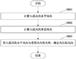
- FIG. 8 shows a flowchart of the steps of determining a target wind direction according to an exemplary embodiment of the present disclosure
- Fig. 9 shows a block diagram of a feedforward control device of a wind turbine according to an exemplary embodiment of the present disclosure
- Fig. 10 shows a block diagram of a control system of a wind turbine according to an exemplary embodiment of the present disclosure.
- Fig. 1 shows a flowchart of a feedforward control method of a wind turbine according to an exemplary embodiment of the present disclosure.
- step S10 the inflow wind information at a plurality of spatial points in front of the wind turbine generator is acquired by the remote sensing measurement device.
- the inflow wind information may include, but is not limited to, the wind speed of the inflow wind at each spatial point position.
- a remote sensing measurement device may be provided on the top of the nacelle of the wind turbine generator for detecting inflow wind information at multiple spatial points.
- the inflow wind information at multiple spatial point positions is acquired from the remote sensing measurement device.
- the remote sensing measurement device may refer to a non-contact, long-distance detection technology.
- the remote sensing measurement device may include but not limited to laser radium, and other devices may also be used to detect the inflow wind information at each spatial point position, such as , Ultrasonic wind measuring device.
- the above-mentioned multiple spatial points are located in front of the impeller plane of the wind turbine (that is, on the windward side).
- the laser beam is emitted to the front of the impeller plane to detect the impeller plane of the wind turbine. Inflow wind information at multiple spatial points in front of.
- Fig. 2 shows a schematic diagram of the remote sensing measurement device detecting inflow wind information at multiple spatial point positions according to an exemplary embodiment of the present disclosure.
- the remote sensing measurement device is a laser radium as an example. It is assumed that the laser radium emits four beams. Based on the emitted beams, the laser radium can detect multiple spatial points on each beam. Inflow wind information at the location.
- the space point with the same distance as the laser radium forms a cross section.
- the laser radium has multiple cross sections, that is, multiple space points are distributed in multiple different cross sections, and the multiple different cross sections have different distances from the wind turbine.
- each section can be parallel to the plane of the impeller.
- the distance between the section and the laser radium refers to the detection distance, and the position of section N can refer to the farthest distance the laser radium can detect.
- Fig. 3 shows a schematic diagram of a two-dimensional spatial distribution of inflow wind information at multiple spatial point positions detected by a remote sensing measurement device according to an exemplary embodiment of the present disclosure.
- the position of each spatial point on the beam includes not only the distance value from the remote sensing measurement device (that is, the detection distance along the centerline of the beam), but also The height value of the space point (such as height z, height z+k), therefore, the wind speed of the inflow wind at each space point at different detection distances and different heights can be detected by the remote sensing measuring device.
- the inflow wind information at each spatial point position detected by the remote sensing measuring device may include the wind speed along the direction of the beam center line and the wind speed in the direction perpendicular to the beam center line.
- RAW i,j is the wind speed of the inflow wind of the i-th beam of the remote sensing measuring device at the j-th section
- U i,j is the ith beam along the beam centerline at the j-th section
- the wind speed in the direction, Vi ,j is the wind speed of the i-th beam perpendicular to the beam centerline at the j-th section
- ⁇ i is the zenith angle of the i-th beam
- the predetermined plane refers to the plane in the middle of the upper and lower beams of the remote sensing measuring device.
- both the zenith angle and the azimuth angle are inherent parameters of the remote sensing measurement device.
- step S20 the target wind speed is synthesized by using the acquired inflow wind information at the multiple spatial point positions.
- the induction effect In front of the impeller of the wind turbine, due to the obstruction of the impeller, an area where the wind speed is lower than the incoming wind speed will appear. This phenomenon is called the induction effect.
- the area where the wind speed is weakened by the induction effect is called the induction zone.
- the existing remote sensing measurement device wind measurement method is susceptible to the inductive effect, resulting in inaccurate wind speed measurement.
- the target wind speed is obtained through wind speed synthesis, thereby removing the influence of the inductive effect on the wind speed, so as to obtain a more accurate inflow wind speed, and realize precise control of the wind turbine based on the inflow wind speed.
- the target wind speed obtained after synthesis is the wind speed of the inflow wind that is not affected by the induction effect.
- the remote sensing measurement device can emit multiple beams to detect the inflow wind information at different cross-sections. Based on this, in the exemplary embodiment of the present disclosure, it is proposed that wind speed synthesis can be performed for each beam or for each beam. Wind speed synthesis is performed on the cross-section, and the different wind speed synthesis methods will be introduced separately below.
- wind speed synthesis is performed based on each section of the remote sensing measurement device to obtain the target wind speed.
- the average wind speed of the section is determined based on the inflow wind information at each spatial point position of the section, and the target wind speed is obtained based on the average wind speed of each section.
- the cross-sectional average wind speed of any cross-section may be the average value of the wind speed of the inflow wind at each spatial point position of the any cross-section.
- the present disclosure is not limited to this, and the average cross-sectional wind speed can also be calculated in other ways, for example, selecting the median value or the average value of the maximum and minimum wind speeds of the inflow wind at each spatial point position of any cross-section, etc. .
- the following will exemplarily introduce the method of obtaining the target wind speed based on the average wind speed of each section.
- the target wind speed can be obtained according to the cross-sectional average wind speed of all cross-sections and the corresponding inductive effect coefficients of all cross-sections.
- each cross-section set the corresponding weight value for the cross-section, calculate the ratio of the average wind speed of the cross-section to the inductive effect coefficient corresponding to the cross-section, and calculate the ratio of the calculated ratio for each cross-section to the corresponding weight value.
- the weighted sum is determined as the target wind speed.
- the inductive effect influence coefficient corresponding to each section varies with the distance from each spatial point to the impeller plane.
- the inductive effect coefficient corresponding to each section can be determined in the following manner.
- the reference section can be any one of all sections.
- the reference section may be a section at a position where the wind speed is least affected by the induced effect among all sections.
- the historical wind resource data of the wind turbine can be used to find the position in front of the impeller plane of the wind turbine that is least affected by the induced effect, and the section at that position (or the section closest to the position) among all the sections is determined as the reference section.
- the reference section may also be selected in other ways. For example, a section may be selected from all sections as the reference section based on experience.
- the inductive effect coefficient corresponding to the reference cross section can be set to 1, and the inductive effect coefficient corresponding to the reference cross section can be adjusted according to the distance between other cross sections and the reference cross section. For example, as the distance between each other cross-section and the reference cross-section increases, the inductive effect coefficient corresponding to each other cross-section gradually decreases from 1.
- the inductive effect influence coefficient corresponding to any other cross section may be the reciprocal of the distance between the any other cross section and the reference cross section.
- the historical wind resource data of the wind turbine can also be used to determine the inductive effect coefficient corresponding to each section through a machine learning algorithm.
- the historical wind resource data may include the actual wind speed and the detected wind speed of the inflow wind at each cross-section, and based on this, build data samples of the machine learning algorithm, and obtain the inductive effect influence coefficient corresponding to each cross-section through the machine learning algorithm.
- the machine learning algorithm may include but is not limited to ELM (Extreme Learning Machine), and may also be other machine learning algorithms.
- the target wind speed can also be obtained by eliminating the time phase difference of the cross-sectional average wind speed of each section.
- the influence coefficient of a given induction effect can be determined in the following manner.
- the inductive effect coefficient corresponding to each cross-section can be obtained by adjusting the inductive effect coefficient of the reference cross-section as described above.
- the above-mentioned method of determining the influence coefficient of a given inductive effect given in the exemplary embodiments of the present disclosure is only an example, and the influence coefficient of a given inductive effect may also be determined in other ways, for example, the given inductive effect
- the influence coefficient can be set based on experience.
- the intermediate wind speed can be obtained in the following way.
- For each section determine the estimated wind speed when the inflow wind flows from the section to the specified section according to the distance from the section to the specified section and the average wind speed of the section, and determine the average of all estimated wind speeds as the intermediate wind speed.
- the estimated wind speed when the inflow wind flows from any cross section to a specified cross section can be determined in the following way.
- the flow time required for the inflow wind to flow from any section to the designated section is calculated; the section of the designated section determined after the flow time has elapsed
- the average wind speed is determined as the estimated wind speed when the inflow wind flows from any section to the specified section.
- the above-mentioned designated section may be any one of all sections.
- the ratio of the distance from any section to the designated section to the average wind speed of any section can be determined as the inflow wind flowing from any section to Specify the flow time required for the section.
- the above method of removing the time phase difference of the average wind speed of multiple sections to synthesize the intermediate wind speed considering that the wind speeds of the inflow wind at different section positions at any time are different, and the time required for the inflow wind to flow from different sections to the impeller plane Also different. Assuming that the wind flow field space is frozen, based on the distance between two adjacent sections and the average wind speed of the section, the flow time required for the inflow wind to flow within this distance can be calculated.
- the inflow wind information at each spatial point position is acquired in real time, and the cross-sectional average wind speed of each section is calculated in real time.
- the wind speed of the inflow wind at each spatial point position obtained when the inflow wind flows to the designated section after the flow time has passed, and the section average wind speed of the designated section calculated at this time is determined as The wind speed is estimated, and the average value of the estimated wind speed when the inflow wind flows from each section to the specified section is determined as the intermediate wind speed.
- wind speed synthesis is performed based on each beam emitted by the laser laser to obtain the target wind speed.
- the combined wind speed of any beam can be determined by the following method: set the corresponding weight value for each spatial point position, calculate the inflow wind information at each spatial point position on the any beam and the corresponding inductive effect influence
- the ratio of the coefficients is determined by the weighted summation of each ratio and the corresponding weight value as the beam composite wind speed of any beam.
- the aforementioned method of determining the inductive effect coefficient corresponding to each cross-section can be referred to to determine the inductive effect coefficient corresponding to each spatial point position.
- the target wind speed may also be obtained based on a wind speed fitting curve.
- wind speed synthesis can be performed based on a beam of ultrasonic waves emitted by the ultrasonic wind measurement device.
- the target wind speed is obtained based on the wind speed fitting curve of the inflow wind information at multiple spatial point positions.
- the wind speed change curve of the inflow wind flowing from the target point to the impeller plane is obtained, and the obtained wind speed change curve is integrated, and the integrated area is compared to the target point.
- the ratio of the distance to the impeller plane is determined as the target wind speed.
- Fig. 4 shows a schematic diagram of a wind speed change curve according to an exemplary embodiment of the present disclosure.
- the target point can be any point within a finite distance from the impeller plane, and the target point can be an inflow point within a finite distance from the impeller plane without the influence of inductive effects (for example, point Q shown in Fig. 4) .
- the target wind speed may be defined as the wind speed of the inflow wind at the target point.
- various fitting, filtering, and smoothing methods can be used to obtain the wind speed change curve of the inflow wind from the target point to the impeller plane (that is, the smooth wind speed change curve) , To determine the target wind speed based on the wind speed change curve.
- the methods of fitting, filtering, and smoothing multiple values are common knowledge in the art, and the content of this part will not be repeated in this disclosure.
- different calculation methods can be selected based on the location of the target point to determine the target wind speed.
- the turbulent freezing theory is introduced, and it is assumed that the wind flow domain in front of the impeller plane has not evolved. If the position of the target point Q x OPT (that is, the distance from the target point to the impeller plane of the wind turbine) is greater than or Equal to the farthest detection distance D(N) of the remote sensing measuring device, the method shown in the following formula (2) can be used to calculate the target wind speed.
- U OPT is the target wind speed
- RAWS j is the average wind speed of the j-th section of the remote sensing measurement device
- x OPT is the distance from the target point to the impeller plane
- x j is the distance from the j-th section to the impeller plane.
- Distance, 1 ⁇ j ⁇ n, n is the number of cross-sections used to calculate the target wind speed
- t m is the flow time required for the inflow wind to flow from the target point to the impeller plane
- Is the average wind speed of the inflow wind from the jth section to the adjacent j-1th section.
- the method shown in formula (3) can be used to calculate the target wind speed.
- the wind speed of the above formula (2) and formula (3) can be obtained by removing the time phase difference of the cross-sectional average wind speed of each section and then performing the average calculation to obtain the target wind speed that is not affected by the induction.
- the average wind speed in the above formula It can be obtained by using the wind speed change curve shown in Figure 4.
- the wind speed change curve from the jth section to the adjacent j-1th section can be integrated, and the ratio of the integral area to the distance difference ⁇ d between the two sections can be determined as the average wind speed
- ⁇ U represents the difference between the average wind speeds of the two sections
- t j represents the flow time required for the inflow wind to flow from the Nth section to the jth section.
- the flow field in front of the impeller is affected by the input of multiple spatial points.
- the flow wind information is synthesized to obtain the target wind speed that is not affected by the induction effect, which is used in the active control and evaluation of the wind turbine.
- step S30 based on the synthesized target wind speed, the arrival time of the incoming flow required for the inflow wind at the target point to reach the impeller plane is predicted.
- the turbulence freezing theory when predicting the arrival time of the incoming flow, the turbulence freezing theory can be introduced, that is, assuming that the wind flow domain in front of the impeller plane has not evolved, under this precondition, the incoming flow arrival time is predicted based on the synthesized target wind speed. .
- the arrival time can be predicted in the following manner.
- the arrival time of the incoming flow can be predicted based on the distance from the position of the target point to the impeller plane and the target wind speed.
- the ratio of the distance from the position of the target point to the plane of the impeller and the target wind speed can be determined as the arrival time of the incoming flow.
- the arrival time of the incoming flow can be predicted based on the wind speed change curve and the target wind speed.
- the wind speed change curve from the target point to the impeller plane can be integrated, and the ratio of its integrated area to the target wind speed can be integrated , Determined as the arrival time of the inflow wind required by the target point to reach the impeller plane.
- the arrival time of the incoming flow required for the inflow wind at the target point to reach the impeller plane can be predicted.
- a deep learning method can be used to establish in advance the corresponding relationship between the target wind speed and the flow time required for the inflow wind at the target point to reach the impeller plane based on the historical wind resource data of the wind turbine.
- the flow time corresponding to the synthesized target wind speed can be searched according to the pre-established correspondence relationship, and the found flow time can be determined as the arrival time of the incoming flow.
- the target wind speed and flow time used to establish the correspondence relationship may be obtained using the above-mentioned method in the exemplary embodiment of the present disclosure.
- the arrival time of the incoming flow can be calculated in sections to predict the incoming flow arrival time required for the inflow wind at the target point to reach the impeller plane.
- each predetermined section may refer to a section whose distance from the plane of the impeller is greater than the distance from the designated section to the plane of the impeller.
- the arrival time required for the inflow wind at the target point to reach the impeller plane can be predicted by the following formula:
- t OPT is the arrival time required for the inflow wind at the target point to reach the impeller plane
- t b is the first flow time required for the inflow wind to flow from the b-th predetermined section to the designated section a
- t a is the second flow time required for the inflow wind to flow from the designated section a to the plane of the impeller
- c is the number of the predetermined section.
- the ratio of the distance from the b-th section to the designated section a to the average wind speed of the b-th section can be determined as the first flow time t b , or the wind speed from the b-th section to the designated section a
- the change curve is integrated, and the ratio of its integrated area to the average wind speed of the b-th section is determined as the first flow time t b .
- the ratio of the distance from the designated section a to the impeller plane to the average wind speed of the designated section a can be determined as the second flow time t a , or the wind speed change curve from the designated section a to the impeller plane can be integrated , The ratio of its integral area to the average wind speed of the designated section a is determined as the second flow time t a .
- the above formula (4) can be used to predict the arrival time. If the location of the target point Q is greater than the farthest detection distance D(N) of the remote sensing measuring device, then In addition to the first flow time t b and the second flow time t a mentioned above, the third flow time t d should also be included.
- the third flow time t d refers to the inflow wind flowing from the target point to the farthest detection distance D(N ) The required flow time.
- the third flow time t d may be determined by the ratio of the distance from the target point to the farthest detection distance D(N) and the cross-sectional average wind speed at the farthest detection distance D(N).
- the method of predicting the arrival time of the incoming flow based on the target wind speed listed in the above exemplary embodiment of the present disclosure is only an example, and the arrival time of the incoming flow may also be predicted in other ways.
- step S40 feedforward control is performed on the wind turbine according to the predicted arrival time of the incoming flow.
- the target wind speed of the shearing inflow wind outside the induction area can be accurately calculated, so as to perform feedforward control on the wind turbine when the inflow wind arrives.
- FIG. 5 shows a flowchart of the steps of performing feedforward control of a wind turbine according to a predicted arrival time of an incoming flow according to an exemplary embodiment of the present disclosure.
- step S31 the control response time required for the wind turbine generator to execute the feedforward control is determined.
- the time required to perform feedforward control once in the history of the wind turbine can be used as the control response time, or the control response time required for the wind turbine to perform feedforward control can also be artificially set based on experience.
- step S32 according to the predicted arrival time of the incoming flow and the determined control response time, the waiting time for the wind turbine generator to execute the feedforward control is determined.
- the difference between the predicted arrival time of the incoming flow and the determined control response time may be determined as the waiting time for the wind turbine to execute the feedforward control.
- step S33 when the determined waiting time is reached, feedforward control is performed on the wind turbine.
- feedforward control can perform feedforward control on the wind turbine when the predicted arrival time of the incoming flow is reached.
- Fig. 6 shows a flowchart of the steps of performing feedforward control on a wind turbine according to an exemplary embodiment of the present disclosure.
- step S331 when the determined waiting time is reached, the target wind speed at the current moment is determined.
- the inflow wind information at each spatial point position is acquired in real time, and the synthesized target wind speed is calculated in real time.
- the target wind speed at the time when the waiting time is reached is acquired.
- step S332 the control strategy corresponding to the target wind speed at the current moment is determined.
- the wind speed and the control strategy corresponding to the wind speed may be stored in the control strategy look-up table.
- the control strategy look-up table may be searched for a control strategy matching the target wind speed at the current moment.
- control strategy corresponding to the target wind speed based on the control strategy look-up table is only an example, and the present disclosure is not limited to this, and the control strategy corresponding to the target wind speed may also be determined in other ways.
- step S333 the wind turbine generator is controlled to execute the determined control strategy.
- the feedforward control method for a wind turbine can obtain a target wind speed that is not affected by an inductive effect, and can also obtain a target wind direction that is not affected by an inductive effect (which can be referred to as inflow wind). Wind direction), target turbulence intensity, target wind shear factor.
- the feedforward control method of a wind turbine generator may further include: determining the target wind shear factor, target wind direction, and/or target turbulence by using the acquired inflow wind information at multiple spatial point positions strength.
- the target wind shear factor, target wind direction and/or target turbulence intensity at the current moment may also be determined.
- the control strategy executed by controlling the wind turbine may be a control strategy corresponding to at least one of the target wind shear factor, target wind direction, target turbulence intensity, and target wind speed at the current moment.
- control strategy look-up table may store wind resource parameters and control strategies corresponding to the wind resource parameters.
- the wind resource parameters include at least one of wind shear factor, wind direction, turbulence intensity, and wind speed.
- control strategy may include, but is not limited to, at least one of the following items: yaw control, pitch control, load reduction control, shutdown control, and torque adjustment control of the wind turbine.
- the control strategy of the control strategy look-up table can store the control parameters corresponding to the above-mentioned control methods, such as the yaw angle value, the pitch angle value, etc. At this time, the wind resource at the current time can be searched from the control strategy look-up table. Each control parameter under the control strategy corresponding to the parameter is sent to the wind turbine generator so that the wind turbine generator operates based on each control parameter.
- the control strategy may also include calculating predetermined parameters (such as power generation) of the wind turbine, for example, based on the obtained target wind shear factor, target wind direction, target turbulence intensity and/or target wind speed. Evaluate the power generation of wind turbines.
- control strategy corresponding to the target wind speed may be the pitch control of the wind turbine
- control strategy corresponding to the target wind speed and target wind direction may be the yaw control and shutdown control of the wind turbine
- the strategy can be to adjust the torque of the wind turbine. It should be understood that the corresponding relationship between the wind resource parameters and the control strategy listed above is only an example, and the present disclosure is not limited to this, and those skilled in the art can establish a control strategy lookup table according to actual needs.
- the wind turbine will respond to “just in time” through active control, and finally realize “follow the wind and follow the trend”.
- the acquired inflow wind information at multiple spatial point positions can be divided into first inflow wind information and second inflow wind information.
- first inflow wind information may include the inflow wind information at each spatial point above the plane where the beam centerline of the remote sensing measurement device is located
- second inflow wind information may include the inflow wind information located below the plane where the beam centerline of the remote sensing measurement device is located. Inflow wind information at each spatial point location.
- Fig. 7 shows a flowchart of steps of calculating a target wind shear factor according to an exemplary embodiment of the present disclosure.
- step S701 the first synthetic wind speed is obtained by synthesizing the first inflow wind information.
- the average value of the wind speed of the inflow wind at each spatial point position above the plane where the beam center line of the remote sensing measurement device is located can be determined as the first synthetic wind speed, but the present disclosure is not limited to this, and can also be obtained in other ways Synthetic wind speed.
- step S702 the second synthesized wind speed is obtained by synthesizing the second inflow wind information.
- the average value of the wind speed of the inflow wind at each spatial point position below the plane where the beam center line of the remote sensing measurement device is located can be determined as the second synthetic wind speed, but the present disclosure is not limited to this, and can also be obtained in other ways Synthetic wind speed.
- step S703 the average value of the height value of each spatial point position above the plane where the beam center line of the remote sensing measurement device is located is calculated to obtain the first height value.
- the acquired inflow wind information at multiple spatial point positions may also include the height value of each spatial point position. Therefore, at this time, the height value of each spatial point position above the plane where the beam center line of the remote sensing measurement device is located The average value of is determined as the first height value.
- step S704 the average value of the height value of each spatial point position below the plane where the beam center line of the remote sensing measurement device is located is calculated to obtain the second height value.
- step S705 the target wind shear factor is calculated according to the first synthetic wind speed, the second synthetic wind speed, the first height value and the second height value.
- V Shear represents the target wind shear factor (vertical wind shear factor)
- HWS + represents the first synthetic wind speed
- HWS - represents the second synthetic wind speed
- H + represents the first height value
- H - represents the first Two height value.
- the above process is to calculate a target wind shear factor for multiple spatial point positions, but the present disclosure is not limited to this, and the corresponding wind shear factor can also be calculated for each section.
- the target wind shear The factor includes the wind shear factor corresponding to each section.
- the wind shear factor corresponding to any cross-section can be calculated based on the inflow wind information at each spatial point position at any cross-section position, and formula (5) is used to calculate the wind shear factor corresponding to any cross-section.
- FIG. 8 shows a flowchart of steps of determining a target wind direction according to an exemplary embodiment of the present disclosure.
- step S801 the horizontal wind direction of the inflow wind is calculated based on the first inflow wind information, the second inflow wind information, and the zenith angle of each beam of the remote sensing measuring device.
- U + represents the horizontal wind direction of the inflow wind
- It represents the average value of the wind speed of the inflow wind at each spatial point position below the plane where the beam center line of the remote sensing measurement device is located
- ⁇ is the average value of the zenith angle of each beam.
- step S802 the vertical wind direction of the inflow wind is calculated according to the first inflow wind information, the second inflow wind information, the zenith angles of the beams of the remote sensing measuring device, and the azimuth angles of the beams of the remote sensing measuring device and the plane of the beam centerline.
- V + represents the vertical wind direction of the inflow wind, It is the average value of the azimuth angle of each beam and the predetermined plane.
- step S803 the angle between the horizontal wind direction and the vertical wind direction of the inflow wind is determined as the target wind direction.
- ⁇ + represents the target wind direction
- atan2() represents a function used to calculate the angle between the horizontal wind direction and the vertical wind direction of the inflow wind.
- the following describes the steps to determine the target turbulence intensity by using the inflow wind information obtained at multiple spatial point positions.
- the target turbulence intensity can be obtained by the following method: synthesize the target wind speed with the acquired inflow wind information, calculate the wind speed standard deviation of the target wind speed in a predetermined time period and the average wind speed of the target wind speed in the predetermined time period, and calculate the wind speed standard The ratio of the difference to the average wind speed is determined as the target turbulence intensity.
- the above process is to calculate a target turbulence intensity for multiple spatial point positions, but the present disclosure is not limited to this, and the corresponding turbulence intensity can also be calculated for each section.
- the target turbulence intensity includes the turbulence intensity corresponding to each section.
- the turbulence intensity corresponding to any cross-section can be calculated based on the inflow wind information at each spatial point position at the any cross-section position, and the turbulence intensity corresponding to any cross-section can be calculated using the methods listed above.
- the above methods for determining the target wind direction, the target wind shear factor, and the target turbulence intensity are only examples.
- the present disclosure is not limited to this, and the target wind direction, the target wind shear factor, and the target turbulence intensity can also be determined by other methods. .
- Fig. 9 shows a block diagram of a feedforward control device of a wind turbine according to an exemplary embodiment of the present disclosure.
- the feedforward control device of the wind turbine includes: an inflow wind information acquisition module 10, a wind speed synthesis module 20, a time prediction module 30 and a feedforward control module 40.
- the inflow wind information acquisition module 10 acquires the inflow wind information at multiple spatial point positions in front of the wind turbine through a remote sensing measurement device.
- multiple spatial points are distributed in multiple different sections, and the multiple different sections have different distances from the wind turbine.
- the inflow wind information may include, but is not limited to, the wind speed of the inflow wind at each spatial point position.
- a remote sensing measurement device may be provided on the top of the nacelle of the wind turbine to detect the inflow wind information at multiple spatial points.
- the inflow wind information acquisition module 10 can acquire inflow wind information at multiple spatial point positions from the remote sensing measurement device.
- the remote sensing measurement device may include but is not limited to laser radium.
- the wind speed synthesis module 20 uses the acquired inflow wind information to synthesize the target wind speed.
- the wind speed synthesis module 20 may perform wind speed synthesis for each light beam or wind speed synthesis for each cross section. The following will separately introduce different wind speed synthesis methods.
- the wind speed synthesis module 20 performs wind speed synthesis based on each section of the remote sensing measurement device to obtain the target wind speed.
- the wind speed synthesis module 20 determines the average wind speed of the section according to the inflow wind information at each spatial point position of the section, and obtains the target wind speed according to the average wind speed of each section.
- the cross-sectional average wind speed of any cross-section may be the average value of the wind speed of the inflow wind at each spatial point position of the any cross-section.
- the following introduces two ways to obtain the target wind speed based on the average wind speed of each section.
- the wind speed synthesis module 20 can obtain the target wind speed according to the cross-sectional average wind speed of all the cross-sections and the inductive effect influence coefficient corresponding to all the cross-sections.
- the wind speed synthesis module 20 sets a corresponding weight value for the section, calculates the ratio of the average wind speed of the section to the inductive effect coefficient corresponding to the section, and compares the ratio calculated for each section to the corresponding The weighted summation of the weight values of is determined as the target wind speed.
- the wind speed synthesis module 20 may determine the inductive effect influence coefficient corresponding to each section in the following manner.
- the inductive effect coefficient of the reference cross-section is used to obtain the inductive effect coefficient of other cross sections.
- the reference section can be any one of all sections. Ground, the reference section may be the section at the position where the wind speed is least affected by the induced effect among all sections.
- the wind speed synthesis module 20 can obtain the target wind speed by eliminating the time phase difference of the cross-sectional average wind speed of each section.
- the wind speed synthesis module 20 obtains the intermediate wind speed by synthesizing the cross-sectional average wind speed of each cross-section to remove the time phase difference between the cross-sectional average wind speed of each cross-section, and obtains the target wind speed according to the intermediate wind speed and a given inductive effect coefficient.
- the wind speed synthesis module 20 can determine the influence coefficient of a given induction effect in the following manner.
- the wind speed synthesis module 20 may obtain the intermediate wind speed in the following manner.
- For each section determine the estimated wind speed when the inflow wind flows from the section to the specified section according to the distance from the section to the specified section and the average wind speed of the section, and determine the average of all estimated wind speeds as the intermediate wind speed.
- the wind speed synthesis module 20 can determine the estimated wind speed when the inflow wind flows from any cross section to a specified cross section in the following manner.
- the flow time required for the inflow wind to flow from any section to the designated section is calculated; the section of the designated section determined after the flow time has elapsed
- the average wind speed is determined as the estimated wind speed when the inflow wind flows from any section to the specified section.
- the wind speed synthesis module 20 performs wind speed synthesis based on each light beam emitted by the remote sensing measurement device to obtain the target wind speed.
- the wind speed synthesis module 20 determines the light beam according to the inflow wind information at each spatial point position on the beam and the inductive effect influence coefficient corresponding to each spatial point position The combined wind speed of all beams is determined as the target wind speed.
- the wind speed synthesis module 20 can determine the beam synthesis wind speed of any beam in the following manner: set a corresponding weight value for each spatial point position, and calculate the inflow wind information at each spatial point position on the any beam and the corresponding The ratio of the inductive effect influence coefficient of, and the weighted sum of each ratio and the corresponding weight value is determined as the beam composite wind speed of any beam.
- the target wind speed may also be obtained based on a wind speed fitting curve.
- the wind speed synthesis module 20 obtains the target wind speed based on the wind speed fitting curve of the inflow wind information at multiple spatial point positions.
- the wind speed synthesis module 20 obtains the wind speed change curve of the inflow wind from the target point to the impeller plane according to the obtained inflow wind information at multiple spatial point positions, integrates the obtained wind speed change curve, and integrates the area The ratio of the distance from the target point to the impeller plane is determined as the target wind speed.
- the time prediction module 30 predicts the arrival time of the incoming flow required for the inflow wind at the target point to reach the impeller plane based on the synthesized target wind speed.
- the time prediction module 30 can predict the arrival time of the incoming flow according to the distance from the position of the target point to the impeller plane and the target wind speed.
- the time prediction module 30 may determine the ratio of the distance from the position of the target point to the impeller plane to the target wind speed as the arrival time of the incoming flow.
- the time prediction module 30 can predict the arrival time of the incoming flow according to the wind speed change curve and the target wind speed.
- the time prediction module 30 can integrate the wind speed change curve from the target point to the impeller plane, and the integrated area is compared with The ratio of the target wind speed is determined as the arrival time of the incoming flow required for the inflow wind at the target point to reach the plane of the impeller.
- the time prediction module 30 can predict the arrival time of the incoming flow required for the inflow wind at the target point to reach the impeller plane according to the corresponding relationship between the target wind speed and the arrival time of the incoming flow.
- the time prediction module 30 may pre-establish the corresponding relationship between the target wind speed and the flow time required for the inflow wind at the target point to reach the impeller plane.
- the time prediction module 30 can search for the flow time corresponding to the synthesized target wind speed according to the pre-established correspondence, and determine the found flow time as the arrival time of the incoming flow.
- the time prediction module 30 can predict the arrival time of the incoming flow required for the inflow wind at the target point to reach the impeller plane by calculating the arrival time of the incoming flow in sections.
- the time prediction module 30 can calculate the first flow time required for the inflow wind to flow from each predetermined section to the designated section and the second flow time required for the inflow wind to flow from the designated section to the plane of the impeller, and calculate the first The sum of the flow time and the second flow time is determined as the incoming flow arrival time required for the inflow wind at the target point to reach the impeller plane.
- each predetermined section may refer to a section whose distance from the plane of the impeller is greater than the distance from the designated section to the plane of the impeller.
- the feedforward control module 40 performs feedforward control of the wind turbine according to the predicted arrival time of the incoming flow.
- the feedforward control module 40 can determine the control response time required for the wind turbine to perform the feedforward control, and determine the waiting time for the wind turbine to perform the feedforward control according to the predicted arrival time and the determined control response time. When the determined waiting time is reached, feed forward control is performed on the wind turbine.
- the difference between the predicted arrival time of the incoming flow and the determined control response time may be determined as the waiting time for the wind turbine to execute the feedforward control.
- the feedforward control module 40 can perform feedforward control of the wind turbine generator in the following manner: when the determined waiting time is reached, the target wind speed at the current moment is determined, and the control strategy corresponding to the target wind speed at the current moment is determined. Control the wind turbine to implement the determined control strategy.
- the wind speed and the control strategy corresponding to the wind speed may be stored in the control strategy look-up table.
- the feedforward control module 40 may search the control strategy look-up table for a control strategy that matches the target wind speed at the current moment.
- the feedforward control device of a wind turbine can obtain a target wind direction, a target turbulence intensity, and a target wind speed that are not affected by an inductive effect, in addition to obtaining a target wind speed that is not affected by an inductive effect.
- Target wind shear factor can be obtained.
- the feedforward control device of a wind turbine generator may further include: a target parameter determination module (not shown in the figure), which uses the acquired inflow wind information at multiple spatial point positions, Determine the target wind shear factor, target wind direction and/or target turbulence intensity.
- a target parameter determination module (not shown in the figure), which uses the acquired inflow wind information at multiple spatial point positions, Determine the target wind shear factor, target wind direction and/or target turbulence intensity.
- the feedforward control module 40 may determine the target wind shear factor, target wind direction, and/or target turbulence intensity at the current moment in addition to determining the target wind speed at the current moment.
- the control strategy executed by controlling the wind turbine may be a control strategy corresponding to at least one of the target wind shear factor, target wind direction, target turbulence intensity, and target wind speed at the current moment.
- control strategy look-up table may store wind resource parameters and control strategies corresponding to the wind resource parameters.
- the wind resource parameters include at least one of wind shear factor, wind direction, turbulence intensity, and wind speed.
- the inflow wind information at the multiple spatial point positions acquired by the inflow wind information acquisition module 10 may be divided into the first inflow wind information and the second inflow wind information.
- the first inflow wind information may include the inflow wind information at each spatial point above the plane where the beam centerline of the remote sensing measurement device is located
- the second inflow wind information may include the inflow wind information located below the plane where the beam centerline of the remote sensing measurement device is located. Inflow wind information at each spatial point location.
- the process of determining the target wind shear factor, target wind direction, and target turbulence intensity by the target parameter determination module is respectively introduced below.
- the target parameter determination module can calculate the target wind shear factor in the following manner.
- the target parameter determination module can obtain the first synthesized wind speed by synthesizing the first inflow wind information, and obtain the second synthesized wind speed by synthesizing the second inflow wind information, and calculate the distance above the plane where the beam centerline of the remote sensing measurement device is located.
- the average value of the height value of each spatial point position is obtained, and the first height value is obtained.
- the average value of the height value of each spatial point position under the plane where the beam center line of the remote sensing measurement device is located is calculated to obtain the second height value.
- the synthetic wind speed, the second synthetic wind speed, the first height value and the second height value are used to calculate the target wind shear factor.
- the target parameter determination module can determine the target wind direction in the following manner.
- the target parameter determination module can calculate the horizontal wind direction of the inflow wind according to the first inflow wind information, the second inflow wind information, and the zenith angle of each beam of the remote sensing measurement device, and according to the first inflow wind information, the second inflow wind information,
- the zenith angle of each beam of the remote sensing measurement device and the azimuth angle of each beam of the remote sensing measurement device and the plane of the beam centerline are used to calculate the vertical wind direction of the inflow wind, and determine the angle between the horizontal and vertical wind directions of the inflow wind as the target wind direction.
- the target parameter determination module can determine the target turbulence intensity in the following manner.
- the target parameter determination module can use the acquired inflow wind information to synthesize the target wind speed, calculate the wind speed standard deviation of the target wind speed in a predetermined time period and the average wind speed of the target wind speed in the predetermined time period, and combine the wind speed standard deviation and the average wind speed The ratio of is determined as the target turbulence intensity.
- Fig. 10 shows a block diagram of a controller of a wind turbine according to an exemplary embodiment of the present disclosure.
- the controller of the wind turbine generator includes: a processor 100, a memory 200 for storing a computer program, and an input/output interface 300, which is used by the processor When 100 is executed, the above-mentioned feedforward control method of the wind turbine is realized.
- the input/output interface 300 is used to connect various input/output devices.
- the controller may be a main controller inside the wind turbine generator set, or a sub-controller that interacts with the main controller.
- the controller may also be a controller deployed in a centralized control system of a wind farm, and is used to send instructions to all wind power generators in the wind farm.
- the instructions include control instructions or operation scheduling instructions from the power grid.
- the feedforward control method of the wind turbine generator shown in FIG. 1 may be executed in the processor 100 shown in FIG. 10.
- the modules shown in Figure 9 can be implemented by general-purpose hardware processors such as digital signal processors, field programmable gate arrays, etc., can also be implemented by dedicated hardware processors such as dedicated chips, or can be implemented entirely through computer programs. It is implemented in software, for example, it may be implemented as various modules in the processor 100 shown in FIG. 10.
- the storage 200 may include: a data storage 210 for storing inflow wind information at a plurality of spatial point positions acquired from a remote sensing measurement device.
- the data storage 210 may be various storages capable of storing data for a long time.
- the processor 100 After the processor 100 obtains the inflow wind information at multiple spatial point positions from the remote sensing measurement device, it stores the obtained inflow wind information in the data storage 210. In addition, the processor 100 may also store the obtained target wind speed, target wind direction, target wind shear factor, and target turbulence intensity in the data storage 210.
- control strategy look-up table can be stored in the processor 100.
- directly searching locally can increase the processing speed.
- present disclosure is not limited to this.
- the control strategy look-up table can also be stored in other memory besides the processor.
- the control strategy look-up table can be stored in the data storage 210.
- the data storage 210 reads and searches the control strategy look-up table, which can reduce the storage burden of the processor.
- the memory 200 may further include: a data buffer 220.
- the data buffer 220 is a storage unit with a fixed storage capacity, and the storage unit only stores the current time to the forward value. For the input data of a certain length of time, as the subsequent data is continuously input, the previously stored data is automatically overwritten.
- the data buffer 220 may be various memories capable of storing data for a short period of time for the processor 100 to use.
- the target wind speed, target wind direction, target wind shear factor, and target turbulence intensity obtained by the processor 100 may be stored in the data memory 210 or in the data buffer 220.
- the processor 100 can search the data buffer 220 for the target wind speed (or other wind resource parameters) calculated at the current moment (the moment when the waiting time is reached), and obtain the target wind speed (or other wind resource parameters) based on the current moment.
- the target wind speed is to search for a matching control strategy from the control strategy lookup table to control the wind turbine to perform actions.
- a control system of a wind turbine including a remote sensing measurement device and a controller.
- the remote sensing measurement device detects inflow wind information at multiple spatial points in front of the wind turbine.
- multiple spatial points are distributed on multiple different cross sections, and the multiple different cross sections have different distances from the wind turbine.
- the remote sensing measurement device may be set on the top of the nacelle of the wind turbine.
- the remote sensing measurement device may include, but is not limited to, laser radium.
- the controller obtains the inflow wind information at multiple spatial point positions from the remote sensing measurement device, so as to realize the above-mentioned feedforward control method of the wind turbine.
- Exemplary embodiments according to the present disclosure also provide a computer-readable storage medium storing a computer program.
- the computer-readable storage medium stores a computer program that, when executed by a processor, causes the processor to execute the above-mentioned feedforward control method of the wind turbine.
- the computer-readable recording medium is any data storage device that can store data read by a computer system. Examples of the computer-readable recording medium include read-only memory, random access memory, read-only optical disk, magnetic tape, floppy disk, optical data storage device, and carrier wave (such as data transmission through the Internet via a wired or wireless transmission path).
- the wind speed of the inflow wind that is not affected by the induction effect is obtained through an effective wind speed synthesis method, which avoids the measurement of wind speed by the existing wind measuring device The problem of inaccuracy.
- the influence of the induction effect can be effectively corrected, and the wind speed, direction, turbulence intensity and wind shear of the inflow wind that are not affected by the induction effect can be obtained.
- the wind speed is obtained by synthesizing the inflow wind information at multiple spatial point positions, which is compared with the currently widely used induced effect. In terms of measuring wind speed at a single point in space, the wind speed value of the inflow wind obtained is more accurate.
Landscapes
- Engineering & Computer Science (AREA)
- Life Sciences & Earth Sciences (AREA)
- Sustainable Development (AREA)
- Sustainable Energy (AREA)
- Chemical & Material Sciences (AREA)
- Combustion & Propulsion (AREA)
- Mechanical Engineering (AREA)
- General Engineering & Computer Science (AREA)
- Wind Motors (AREA)
- Indicating Or Recording The Presence, Absence, Or Direction Of Movement (AREA)
Abstract
Description


Claims (28)
- 一种风电机组的前馈控制方法,包括:通过遥感测量装置获取所述风电机组前方的多个空间点位置处的入流风信息,所述多个空间点分布在多个不同的截面,所述多个不同的截面相对所述风电机组的距离不同;利用获取的入流风信息合成目标风速;基于合成的目标风速,预测目标点的入流风到达叶轮平面所需的来流到达时间;根据所预测的来流到达时间对风电机组进行前馈控制。
- 如权利要求1所述的前馈控制方法,其中,利用获取的入流风信息合成目标风速包括:针对入流风的每个截面,根据处于该截面的各空间点位置处的入流风信息,确定该截面的截面平均风速;根据各截面的截面平均风速来获得目标风速。
- 如权利要求2所述的前馈控制方法,其中,利用获取的入流风信息合成目标风速还包括:确定每个截面对应的诱导效应影响系数,其中,根据各截面的截面平均风速来获得目标风速包括:根据所有截面的截面平均风速以及对应的诱导效应影响系数,获得目标风速。
- 如权利要求3所述的前馈控制方法,其中,确定每个截面对应的诱导效应影响系数包括:从所有截面中选择一截面作为参考截面;设定所述参考截面的诱导效应影响系数;根据所有截面中除所述参考截面之外的其他截面与所述参考截面之间的距离,调整所述参考截面的诱导效应影响系数,以获得所述其他截面的诱导效应影响系数。
- 如权利要求3所述的前馈控制方法,其中,根据所有截面的截面平均风速以及对应的诱导效应影响系数,获得目标风速包括:为每个截面设置对应的权重值;分别计算每个截面的截面平均风速与对应的诱导效应影响系数的比值,将每个比值与对应的权重值的加权求和确定为目标风速。
- 如权利要求2所述的前馈控制方法,其中,根据各截面的截面平均风速来获得目标风速包括:通过对各截面的截面平均风速进行合成,获得中间风速,以去除各截面的截面平均风速之间的时间相位差;根据中间风速与给定诱导效应影响系数,获得目标风速;其中,通过以下方式确定给定诱导效应影响系数:为每个截面设置对应的权重值;确定每个截面对应的诱导效应影响系数;将每个截面对应的诱导效应影响系数与对应的权重值的加权求和,确定为所述给定诱导效应影响系数。
- 如权利要求6所述的前馈控制方法,其中,通过对各截面的截面平均风速进行合成,获得中间风速包括:针对每个截面,根据该截面到指定截面的距离以及该截面的截面平均风速,确定入流风由该截面流动到所述指定截面时的估测风速;将所有估测风速的平均值确定为中间风速。
- 如权利要求7所述的前馈控制方法,其中,通过以下方式确定入流风由任一截面流动到所述指定截面时的估测风速:根据所述任一截面到所述指定截面的距离以及所述任一截面的截面平均风速,计算入流风由所述任一截面流动到所述指定截面所需的流动时间;将经过所述流动时间之后所确定的所述指定截面的截面平均风速,确定为入流风由所述任一截面流动到所述指定截面时的估测风速。
- 如权利要求1所述的前馈控制方法,其中,所述遥感测量装置包括激光镭达。
- 如权利要求9所述的前馈控制方法,其中,利用获取的入流风信息合成目标风速包括:针对激光镭达发射的每根光束,根据该光束上的各空间点位置处的入流风信息以及与各空间点位置处对应的诱导效应影响系数,确定该光束的光束合成风速;将所有光束的光束合成风速的平均值,确定为目标风速。
- 如权利要求10所述的前馈控制方法,其中,通过以下方式确定任一光束的光束合成风速:为每个空间点位置设置对应的权重值;计算所述任一光束上的每个空间点位置处的入流风信息与对应的诱导效应影响系数的比值,将每个比值与对应的权重值的加权求和确定为所述任一光束的光束合成风速。
- 如权利要求1所述的前馈控制方法,其中,基于合成的目标风速,预测目标点的入流风到达叶轮平面所需的来流到达时间包括:确定目标点所在位置处到叶轮平面的距离;将所确定的距离与合成的目标风速的比值,确定为来流到达时间。
- 如权利要求1所述的前馈控制方法,其中,利用获取的入流风信息合成目标风速包括:根据获取的多个空间点位置处的入流风信息,获得入流风从目标点流动到叶轮平面的风速变化曲线,对获得的风速变化曲线进行积分,将积分面积与目标点到叶轮平面的距离的比值,确定为目标风速,其中,基于合成的目标风速,预测目标点的入流风到达叶轮平面所需的来流到达时间包括:将积分面积与所述目标风速的比值,确定为目标点的入流风到达叶轮平面所需的来流到达时间。
- 如权利要求1所述的前馈控制方法,其中,基于合成的目标风速,预测目标点的入流风到达叶轮平面所需的来流到达时间包括:根据目标风速与来流到达时间的对应关系,查找与合成的目标风速对应的来流到达时间,并将查找到的来流到达时间确定为目标点的入流风到达叶轮平面所需的来流到达时间。
- 如权利要求1所述的前馈控制方法,其中,基于合成的目标风速,预测目标点的入流风到达叶轮平面所需的来流到达时间包括:确定入流风从各预定截面流动到指定截面所需的第一流动时间;确定入流风从指定截面流动到叶轮平面所需的第二流动时间;根据所确定的第一流动时间和第二流动时间,获得目标点的入流风到达叶轮平面所需的来流到达时间。
- 如权利要求15所述的前馈控制方法,其中,基于合成的目标风速,预测目标点的入流风到达叶轮平面所需的来流到达时间还包括:当目标点所在位置大于遥感测量装置的最远探测距离时,还确定入流风从目标点流动到最远探测距离处所需的第三流动时间,其中,根据所确定的第一流动时间、第二流动时间和第三流动时间,获得目标点的入流风到达叶轮平面所需的来流到达时间。
- 如权利要求1所述的前馈控制方法,其中,根据所预测的来流到达时间对风电机组进行前馈控制包括:确定风电机组执行前馈控制所需的控制响应时间;根据所预测的来流到达时间和所确定的控制响应时间,确定风电机组执行前馈控制的等待时间;在到达所确定的等待时间时,对风电机组进行前馈控制。
- 如权利要求17所述的前馈控制方法,其中,风电机组执行前馈控制的等待时间为所预测的来流到达时间与所确定的控制响应时间的差值。
- 如权利要求17所述的前馈控制方法,其中,在到达所确定的等待时间时,对风电机组进行前馈控制包括:在到达所确定的等待时间时,确定当前时刻的目标风速;确定与当前时刻的目标风速所对应的控制策略;控制风电机组执行所确定的控制策略。
- 如权利要求19所述的前馈控制方法,其中,确定与当前时刻的目标风速所对应的控制策略包括:从控制策略查找表中搜索与当前时刻的目标风速匹配的控制策略,其中,控制策略查找表中存储有风速以及与风速对应的控制策略。
- 如权利要求19所述的前馈控制方法,其中,所述前馈控制方法还包括:利用获取的多个空间点位置处的入流风信息,至少确定目标风剪切因子、目标风向或目标湍流强度,其中,在到达所确定的等待时间时,对风电机组进行前馈控制还包括:在到达所确定的等待时间时,还至少确定当前时刻的目标风剪切因子、目标风向或目标湍流强度,其中,所确定的控制策略为与当前时刻的目标风剪切因子、目标风向、目标湍流强度中的至少一项以及目标风速所对应的控制策略。
- 如权利要求21所述的前馈控制方法,其中,获取的入流风信息包括第一入流风信息和第二入流风信息,第一入流风信息包括处于遥感测量装置 的光束中心线所在平面上方的各空间点位置处的入流风信息,第二入流风信息包括处于遥感测量装置的光束中心线所在平面下方的各空间点位置处的入流风信息,其中,确定目标风剪切因子包括:通过对第一入流风信息进行合成获得第一合成风速;通过对第二入流风信息进行合成获得第二合成风速;计算处于遥感测量装置的光束中心线所在平面上方的各空间点位置的高度值的平均值,获得第一高度值;计算处于遥感测量装置的光束中心线所在平面下方的各空间点位置的高度值的平均值,获得第二高度值;根据第一合成风速、第二合成风速、第一高度值和第二高度值,计算目标风剪切因子。
- 如权利要求22所述的前馈控制方法,其中,确定目标风向包括:根据第一入流风信息、第二入流风信息、遥感测量装置各光束的天顶角,计算入流风的水平风向;根据第一入流风信息、第二入流风信息、遥感测量装置各光束的天顶角、遥感测量装置各光束与光束中心线所在平面的方位角,计算入流风的垂直风向;将入流风的水平风向与垂直风向的夹角,确定为目标风向。
- 如权利要求21所述的前馈控制方法,其中,确定目标湍流强度包括:利用获取的多个空间点位置处的入流风信息合成目标风速;计算预定时间段内的目标风速的风速标准差以及风速平均值;将风速标准差与风速平均值的比值,确定为目标湍流强度。
- 一种风电机组的前馈控制装置,其中,包括:入流风信息获取模块,通过遥感测量装置获取所述风电机组前方的多个空间点位置处的入流风信息,所述多个空间点分布在多个不同的截面,所述多个不同的截面相对所述风电机组的距离不同;风速合成模块,利用获取的入流风信息合成目标风速;时间预测模块,基于合成的目标风速,预测目标点的入流风到达叶轮平面所需的来流到达时间;前馈控制模块,根据所预测的来流到达时间对风电机组进行前馈控制。
- 一种风电机组的控制器,其中,包括:处理器;输入\输出接口;存储器,用于存储计算机程序,所述计算机程序在被所述处理器执行时实现如权利要求1至24中任意一项所述的风电机组的前馈控制方法。
- 一种风电机组的控制系统,其中,包括:遥感测量装置,探测所述风电机组前方的多个空间点位置处的入流风信息,所述多个空间点分布在多个不同的截面,所述多个不同的截面相对所述风电机组的距离不同,控制器,从遥感测量装置获取多个空间点位置处的入流风信息,以实现如权利要求1至24中任意一项所述的风电机组的前馈控制方法。
- 一种存储有计算机程序的计算机可读存储介质,其中,当所述计算机程序在被处理器执行时实现如权利要求1至24中任意一项所述的风电机组的前馈控制方法。
Priority Applications (4)
| Application Number | Priority Date | Filing Date | Title |
|---|---|---|---|
| US17/615,095 US12098707B2 (en) | 2019-05-30 | 2019-12-24 | Feedforward control method, apparatus and control system for wind turbine |
| AU2019447706A AU2019447706B2 (en) | 2019-05-30 | 2019-12-24 | Feedforward control method and apparatus for wind turbine generator set, and control system |
| CA3139756A CA3139756A1 (en) | 2019-05-30 | 2019-12-24 | Feedforward control method and apparatus for wind turbine generator set, and control system |
| EP19931285.1A EP3978749A4 (en) | 2019-05-30 | 2019-12-24 | METHOD AND APPARATUS FOR FORWARD COUPLED CONTROL OF A WIND TURBINE GENERATOR SET AND CONTROL SYSTEM |
Applications Claiming Priority (2)
| Application Number | Priority Date | Filing Date | Title |
|---|---|---|---|
| CN201910462953.2A CN112012882B (zh) | 2019-05-30 | 2019-05-30 | 风电机组的前馈控制方法、装置以及控制系统 |
| CN201910462953.2 | 2019-05-30 |
Publications (1)
| Publication Number | Publication Date |
|---|---|
| WO2020238182A1 true WO2020238182A1 (zh) | 2020-12-03 |
Family
ID=73501239
Family Applications (1)
| Application Number | Title | Priority Date | Filing Date |
|---|---|---|---|
| PCT/CN2019/127920 Ceased WO2020238182A1 (zh) | 2019-05-30 | 2019-12-24 | 风电机组的前馈控制方法、装置以及控制系统 |
Country Status (6)
| Country | Link |
|---|---|
| US (1) | US12098707B2 (zh) |
| EP (1) | EP3978749A4 (zh) |
| CN (1) | CN112012882B (zh) |
| AU (1) | AU2019447706B2 (zh) |
| CA (1) | CA3139756A1 (zh) |
| WO (1) | WO2020238182A1 (zh) |
Cited By (1)
| Publication number | Priority date | Publication date | Assignee | Title |
|---|---|---|---|---|
| CN120819470A (zh) * | 2025-09-05 | 2025-10-21 | 华能巴林右旗新能源有限公司 | 风力发电控制方法、装置、设备及计算机可读存储介质 |
Families Citing this family (3)
| Publication number | Priority date | Publication date | Assignee | Title |
|---|---|---|---|---|
| CN112012882B (zh) * | 2019-05-30 | 2022-08-02 | 北京金风科创风电设备有限公司 | 风电机组的前馈控制方法、装置以及控制系统 |
| CN113309663B (zh) * | 2021-03-08 | 2022-11-15 | 新疆金风科技股份有限公司 | 用于风力发电机组的控制方法及控制装置 |
| CN116201698B (zh) * | 2022-11-17 | 2024-10-01 | 盛东如东海上风力发电有限责任公司 | 一种风电机组控制方法及系统 |
Citations (5)
| Publication number | Priority date | Publication date | Assignee | Title |
|---|---|---|---|---|
| CN101368541A (zh) * | 2007-08-13 | 2009-02-18 | 通用电气公司 | 利用逆风信息降低水平轴风力涡轮机中负荷的系统和方法 |
| WO2010061255A2 (en) * | 2008-11-01 | 2010-06-03 | Clipper Windpower, Inc. | Active blade pitch control for reduction of wind turbine noise or loads |
| CN102762852A (zh) * | 2009-12-23 | 2012-10-31 | 维斯塔斯风力系统集团公司 | 用于保护风力涡轮机免受疲劳损坏的方法和装置 |
| CN104364522A (zh) * | 2012-06-15 | 2015-02-18 | 乌本产权有限公司 | 风能设备和用于控制风能设备或风力发电厂的方法 |
| EP1770278B1 (en) * | 2005-09-30 | 2015-06-24 | General Electric Company | System and method for control of a wind turbine based on measured wind speed upstream |
Family Cites Families (6)
| Publication number | Priority date | Publication date | Assignee | Title |
|---|---|---|---|---|
| CN103061980A (zh) * | 2012-12-28 | 2013-04-24 | 东方电气集团东方汽轮机有限公司 | 基于激光测风雷达的风力发电机组的前馈控制系统及其控制方法 |
| WO2016187405A1 (en) * | 2015-05-19 | 2016-11-24 | Ophir Corporation | Systems and methods for predicting arrival of wind event |
| US10539116B2 (en) | 2016-07-13 | 2020-01-21 | General Electric Company | Systems and methods to correct induction for LIDAR-assisted wind turbine control |
| FR3068139B1 (fr) * | 2017-06-21 | 2019-12-20 | IFP Energies Nouvelles | Procede d'acquisition et de modelisation par un capteur lidar d'un champ de vent incident |
| CN108953060B (zh) * | 2018-03-30 | 2020-01-17 | 浙江大学 | 基于激光雷达测风仪的风电场场级偏航控制方法 |
| CN112012882B (zh) * | 2019-05-30 | 2022-08-02 | 北京金风科创风电设备有限公司 | 风电机组的前馈控制方法、装置以及控制系统 |
-
2019
- 2019-05-30 CN CN201910462953.2A patent/CN112012882B/zh active Active
- 2019-12-24 EP EP19931285.1A patent/EP3978749A4/en active Pending
- 2019-12-24 AU AU2019447706A patent/AU2019447706B2/en active Active
- 2019-12-24 WO PCT/CN2019/127920 patent/WO2020238182A1/zh not_active Ceased
- 2019-12-24 US US17/615,095 patent/US12098707B2/en active Active
- 2019-12-24 CA CA3139756A patent/CA3139756A1/en active Pending
Patent Citations (5)
| Publication number | Priority date | Publication date | Assignee | Title |
|---|---|---|---|---|
| EP1770278B1 (en) * | 2005-09-30 | 2015-06-24 | General Electric Company | System and method for control of a wind turbine based on measured wind speed upstream |
| CN101368541A (zh) * | 2007-08-13 | 2009-02-18 | 通用电气公司 | 利用逆风信息降低水平轴风力涡轮机中负荷的系统和方法 |
| WO2010061255A2 (en) * | 2008-11-01 | 2010-06-03 | Clipper Windpower, Inc. | Active blade pitch control for reduction of wind turbine noise or loads |
| CN102762852A (zh) * | 2009-12-23 | 2012-10-31 | 维斯塔斯风力系统集团公司 | 用于保护风力涡轮机免受疲劳损坏的方法和装置 |
| CN104364522A (zh) * | 2012-06-15 | 2015-02-18 | 乌本产权有限公司 | 风能设备和用于控制风能设备或风力发电厂的方法 |
Non-Patent Citations (1)
| Title |
|---|
| See also references of EP3978749A4 * |
Cited By (2)
| Publication number | Priority date | Publication date | Assignee | Title |
|---|---|---|---|---|
| CN120819470A (zh) * | 2025-09-05 | 2025-10-21 | 华能巴林右旗新能源有限公司 | 风力发电控制方法、装置、设备及计算机可读存储介质 |
| CN120819470B (zh) * | 2025-09-05 | 2026-02-24 | 华能巴林右旗新能源有限公司 | 风力发电控制方法、装置、设备及计算机可读存储介质 |
Also Published As
| Publication number | Publication date |
|---|---|
| US20220228557A1 (en) | 2022-07-21 |
| US12098707B2 (en) | 2024-09-24 |
| AU2019447706B2 (en) | 2024-03-07 |
| EP3978749A1 (en) | 2022-04-06 |
| CN112012882A (zh) | 2020-12-01 |
| CN112012882B (zh) | 2022-08-02 |
| CA3139756A1 (en) | 2020-12-03 |
| EP3978749A4 (en) | 2022-08-10 |
| AU2019447706A1 (en) | 2022-01-06 |
Similar Documents
| Publication | Publication Date | Title |
|---|---|---|
| WO2020238182A1 (zh) | 风电机组的前馈控制方法、装置以及控制系统 | |
| CN110632921A (zh) | 机器人路径规划方法、装置、电子设备和存储介质 | |
| CN119758941B (zh) | 一种混凝土浇筑质量智能监控方法、系统、产品和介质 | |
| CN110595472B (zh) | 一种无人船双目标气象航线优化方法和系统 | |
| CN111666716B (zh) | 大型风电机组叶轮面等效风速预测方法 | |
| CN113361149B (zh) | 一种天文台主动反射面的面形调整方法、装置及设备 | |
| CN119779303A (zh) | 一种基于动态环境感知的无人船激光测距优化方法及系统 | |
| CN108918905A (zh) | 风力发电机组风速的预测方法及装置 | |
| CN120926957B (zh) | 一种海洋流场测量方法及装置 | |
| Chen et al. | Path planning of underwater terrain-aided navigation based on improved artificial potential field method | |
| CN120523079A (zh) | 一种轨道交通客服机器人运行控制方法及设备 | |
| CN116736289B (zh) | 基于预测更新网络和动态波门的多机动目标跟踪方法 | |
| JP2018141643A (ja) | ふ仰角算出装置およびふ仰角算出方法 | |
| Yu et al. | Pressure and velocity cross-spectrum of normal modes in low-frequency acoustic vector field of shallow water and its application | |
| WO2023142366A1 (zh) | 估计风力涡轮机转子处风速的方法及装置 | |
| KR20250104763A (ko) | 드론을 이용한 지형 변화 모니터링 시스템 및 방법 | |
| CN116181573A (zh) | 一种风电机组激光雷达的控制方法、装置及介质 | |
| CN121028814B (zh) | 基于动态预测步长的航迹跟踪方法、设备、介质及产品 | |
| CN118067220B (zh) | 一种水深透视探测稳定方法及系统 | |
| CN120653033B (zh) | 一种预冷混凝土生产物联网温控方法及系统 | |
| CN120255582B (zh) | 漂浮式光伏阵列的数据处理方法、装置和计算机设备 | |
| CN113253205B (zh) | 一种水下滑翔机编队的目标观探测方法 | |
| TW202600965A (zh) | 用於控制風場之控制方法、相關電腦程式產品及電子控制裝置 | |
| CN120013412A (zh) | 火电机组存煤量确定方法及装置 | |
| CN120135406A (zh) | 基于多传感器数据的智能船舶航行控制与调节系统及方法 |
Legal Events
| Date | Code | Title | Description |
|---|---|---|---|
| 121 | Ep: the epo has been informed by wipo that ep was designated in this application |
Ref document number: 19931285 Country of ref document: EP Kind code of ref document: A1 |
|
| ENP | Entry into the national phase |
Ref document number: 3139756 Country of ref document: CA |
|
| NENP | Non-entry into the national phase |
Ref country code: DE |
|
| ENP | Entry into the national phase |
Ref document number: 2019447706 Country of ref document: AU Date of ref document: 20191224 Kind code of ref document: A |
|
| ENP | Entry into the national phase |
Ref document number: 2019931285 Country of ref document: EP Effective date: 20220103 |