WO2020240617A1 - 電動機の製造方法、電動機、圧縮機、及び空気調和機 - Google Patents
電動機の製造方法、電動機、圧縮機、及び空気調和機 Download PDFInfo
- Publication number
- WO2020240617A1 WO2020240617A1 PCT/JP2019/020673 JP2019020673W WO2020240617A1 WO 2020240617 A1 WO2020240617 A1 WO 2020240617A1 JP 2019020673 W JP2019020673 W JP 2019020673W WO 2020240617 A1 WO2020240617 A1 WO 2020240617A1
- Authority
- WO
- WIPO (PCT)
- Prior art keywords
- phase coil
- coil
- phase
- rotor
- electric motor
- Prior art date
- Legal status (The legal status is an assumption and is not a legal conclusion. Google has not performed a legal analysis and makes no representation as to the accuracy of the status listed.)
- Ceased
Links
Images










Classifications
-
- H—ELECTRICITY
- H02—GENERATION; CONVERSION OR DISTRIBUTION OF ELECTRIC POWER
- H02K—DYNAMO-ELECTRIC MACHINES
- H02K15/00—Processes or apparatus specially adapted for manufacturing, assembling, maintaining or repairing of dynamo-electric machines
- H02K15/02—Processes or apparatus specially adapted for manufacturing, assembling, maintaining or repairing of dynamo-electric machines of stator or rotor bodies
- H02K15/03—Processes or apparatus specially adapted for manufacturing, assembling, maintaining or repairing of dynamo-electric machines of stator or rotor bodies having permanent magnets
-
- H—ELECTRICITY
- H02—GENERATION; CONVERSION OR DISTRIBUTION OF ELECTRIC POWER
- H02K—DYNAMO-ELECTRIC MACHINES
- H02K15/00—Processes or apparatus specially adapted for manufacturing, assembling, maintaining or repairing of dynamo-electric machines
- H02K15/06—Embedding prefabricated windings in the machines
- H02K15/062—Windings in slots; Salient pole windings
- H02K15/065—Windings consisting of complete sections, e.g. coils or waves
-
- H—ELECTRICITY
- H02—GENERATION; CONVERSION OR DISTRIBUTION OF ELECTRIC POWER
- H02K—DYNAMO-ELECTRIC MACHINES
- H02K15/00—Processes or apparatus specially adapted for manufacturing, assembling, maintaining or repairing of dynamo-electric machines
- H02K15/16—Centring rotors within the stators
-
- H—ELECTRICITY
- H02—GENERATION; CONVERSION OR DISTRIBUTION OF ELECTRIC POWER
- H02K—DYNAMO-ELECTRIC MACHINES
- H02K15/00—Processes or apparatus specially adapted for manufacturing, assembling, maintaining or repairing of dynamo-electric machines
- H02K15/30—Manufacture of winding connections
- H02K15/32—Manufacture of terminal arrangements; Connecting the terminals to external circuits
-
- H—ELECTRICITY
- H02—GENERATION; CONVERSION OR DISTRIBUTION OF ELECTRIC POWER
- H02K—DYNAMO-ELECTRIC MACHINES
- H02K15/00—Processes or apparatus specially adapted for manufacturing, assembling, maintaining or repairing of dynamo-electric machines
- H02K15/30—Manufacture of winding connections
- H02K15/33—Connecting winding sections; Forming leads; Connecting leads to terminals
-
- H—ELECTRICITY
- H02—GENERATION; CONVERSION OR DISTRIBUTION OF ELECTRIC POWER
- H02K—DYNAMO-ELECTRIC MACHINES
- H02K1/00—Details of the magnetic circuit
- H02K1/06—Details of the magnetic circuit characterised by the shape, form or construction
- H02K1/22—Rotating parts of the magnetic circuit
- H02K1/27—Rotor cores with permanent magnets
- H02K1/2706—Inner rotors
- H02K1/272—Inner rotors the magnetisation axis of the magnets being perpendicular to the rotor axis
- H02K1/274—Inner rotors the magnetisation axis of the magnets being perpendicular to the rotor axis the rotor consisting of two or more circumferentially positioned magnets
- H02K1/2753—Inner rotors the magnetisation axis of the magnets being perpendicular to the rotor axis the rotor consisting of two or more circumferentially positioned magnets the rotor consisting of magnets or groups of magnets arranged with alternating polarity
- H02K1/276—Magnets embedded in the magnetic core, e.g. interior permanent magnets [IPM]
- H02K1/2766—Magnets embedded in the magnetic core, e.g. interior permanent magnets [IPM] having a flux concentration effect
-
- H—ELECTRICITY
- H02—GENERATION; CONVERSION OR DISTRIBUTION OF ELECTRIC POWER
- H02K—DYNAMO-ELECTRIC MACHINES
- H02K2213/00—Specific aspects, not otherwise provided for and not covered by codes H02K2201/00 - H02K2211/00
- H02K2213/03—Machines characterised by numerical values, ranges, mathematical expressions or similar information
Definitions
- the present invention relates to an electric motor and a method for manufacturing the electric motor.
- a magnetizing method in which a permanent magnet (specifically, an unmagnetized magnetic material) of a rotor is magnetized using a coil (also referred to as a winding) attached to a stator core.
- a coil also referred to as a winding
- An object of the present invention is to prevent significant deformation of the three-phase coil of the stator when magnetizing with the rotor placed inside the stator.
- the method for manufacturing an electric motor is as follows.
- the electric motor according to another aspect of the present invention
- the rotor Stator iron core and It has a permanent magnet placed on the stator core and In a plane orthogonal to the axial direction of the rotor, one end side of the permanent magnet is when a current flows from the power supply to the first phase coil of the three-phase coil at the center of the magnetic pole of the rotor.
- the compressor With a closed container With the compression device arranged in the closed container, It includes the electric motor that drives the compression device.
- the air conditioner according to another aspect of the present invention is With the compressor Equipped with a heat exchanger.
- the present invention when magnetizing is performed with the rotor arranged inside the stator, it is possible to prevent significant deformation of the three-phase coil of the stator.
- FIG. 1 It is a top view which shows schematic structure of the electric motor which concerns on Embodiment 1 of this invention. It is a top view which shows the structure of a rotor schematicly. It is a top view which shows an example of a stator. It is a figure which shows schematic the internal structure of the stator shown in FIG. It is a schematic diagram which shows an example of the connection in a three-phase coil. It is a figure which shows the example of the connection pattern of a three-phase coil when magnetizing a magnetic material. It is a figure which shows another example of the connection pattern of a three-phase coil when magnetizing a magnetic material. It is a figure which shows still another example of the connection pattern of a three-phase coil when magnetizing a magnetic material.
- connection pattern of a three-phase coil when magnetizing a magnetic material. It is a figure which shows still another example of the connection pattern of a three-phase coil when magnetizing a magnetic material. It is a figure which shows still another example of the connection pattern of a three-phase coil when magnetizing a magnetic material. It is a figure which shows still another example of the connection pattern of a three-phase coil when magnetizing a magnetic material. It is a flowchart which shows an example of the manufacturing process of an electric motor. It is a figure which shows an example of the manufacturing process of an electric motor. It is a figure which shows an example of the manufacturing process of an electric motor. It is a figure which shows an example of the manufacturing process of an electric motor. It is a figure which shows another example of a stator.
- Embodiment 1 In the xyz orthogonal coordinate system shown in each figure, the z-axis direction (z-axis) indicates a direction parallel to the axis Ax of the electric motor 1, and the x-axis direction (x-axis) is orthogonal to the z-axis direction (z-axis).
- the y-axis direction (y-axis) indicates a direction orthogonal to both the z-axis direction and the x-axis direction.
- the axis Ax is the center of the stator 3 and the center of rotation of the rotor 2.
- the direction parallel to the axis Ax is also referred to as "axial direction of rotor 2" or simply "axial direction”.
- the radial direction is the radial direction of the rotor 2 or the stator 3 and is a direction orthogonal to the axis Ax.
- the xy plane is a plane orthogonal to the axial direction.
- the arrow D1 indicates the circumferential direction centered on the axis Ax.
- the circumferential direction of the rotor 2 or the stator 3 is also simply referred to as the "circumferential direction".
- FIG. 1 is a plan view schematically showing the structure of the electric motor 1 according to the first embodiment of the present invention.
- the electric motor 1 has a rotor 2 having a plurality of magnetic poles, a stator 3, and a shaft 4 fixed to the rotor 2.
- the electric motor 1 is, for example, a permanent magnet synchronous motor.
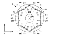
- FIG. 2 is a plan view schematically showing the structure of the rotor 2.
- the rotor 2 is rotatably arranged inside the stator 3.
- the rotor 2 has a rotor core 21 and at least one permanent magnet 22 which is a magnetic material. There is an air gap between the rotor 2 and the stator 3.
- the rotor 2 rotates about the axis Ax.
- the rotor core 21 has a plurality of magnet insertion holes 211 and a shaft hole 212.
- the rotor core 21 may further have at least one flux barrier portion that is a space communicating with each magnet insertion hole 211.
- the rotor 2 has a plurality of permanent magnets 22.
- Each permanent magnet 22 is arranged in each magnet insertion hole 211.
- the shaft 4 is fixed to the shaft hole 212.
- Each permanent magnet 22 provided in the electric motor 1 as a finished product is a magnetized magnetic body 22.
- two permanent magnets 22 adjacent to each other form one magnetic pole of the rotor 2, that is, an N pole or an S pole.
- one permanent magnet 22 may form one magnetic pole of the rotor 2.
- a set of permanent magnets 22 forming one magnetic pole of the rotor 2 are arranged so as to have a V shape.
- the set of permanent magnets 22 forming one magnetic pole of the rotor 2 may be arranged straight.
- each magnetic pole of the rotor 2 is located at the center of each magnetic pole of the rotor 2 (that is, the north pole or the south pole of the rotor 2).
- Each magnetic pole of the rotor 2 (also simply referred to as “each magnetic pole” or “magnetic pole”) means a region that serves as the north pole or the south pole of the rotor 2.
- the center of each magnetic pole of the rotor 2 is indicated by the magnetic pole center line M1.
- the magnetic pole center line M1 passes between the two permanent magnets 22 forming one magnetic pole of the rotor 2 and the axis Ax in the xy plane. That is, in the example shown in FIG. 2, the center of each magnetic pole of the rotor 2 includes a position between two permanent magnets 22 forming one magnetic pole.
- the center of each magnetic pole of the rotor 2 includes the center of one permanent magnet 22 in the xy plane.
- the magnetic pole center line M1 passes through the center of each permanent magnet 22 and the axis Ax.
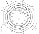
- FIG. 3 is a plan view showing an example of the stator 3.
- FIG. 4 is a diagram schematically showing the internal structure of the stator 3 shown in FIG.
- the stator 3 has a stator core 31 and a three-phase coil 32.
- the stator core 31 has a plurality of slots 311 in which the three-phase coil 32 is arranged. In the example shown in FIG. 3, the stator core 31 has 18 slots 311.
- the three-phase coil 32 is attached to the stator core 31 in a distributed winding manner. As shown in FIG. 4, the three-phase coil 32 has a coil side 32b arranged in the slot 311 and a coil end 32a not arranged in the slot 311. Each coil end 32a is an end of a three-phase coil 32 in the axial direction.
- the three-phase coil 32 includes at least one internal phase coil 321, at least one medium phase coil 322, and at least one external phase coil 323. That is, the three-phase coil 32 has a first phase, a second phase, and a third phase.
- the first phase is the V phase
- the second phase is the W phase
- the third phase is the U phase.
- the three-phase coil 32 forms six magnetic poles.
- the three-phase coil 32 has three internal-phase coils 321, three medium-phase coils 322, and three external-phase coils 323.
- the number of coils in each phase is not limited to three.
- the stator 3 has the structure shown in FIG. 3 at the two coil ends 32a.
- the stator 3 may have a structure shown in FIG. 3 at one of the two coil ends 32a.
- the first-phase coil, the second-phase coil, and the third-phase coil of the three-phase coils 32 are arranged in this order in the circumferential direction of the stator core 31. ing.
- the middle-phase coil 322 in the coil end 32a of the three-phase coil 32, the middle-phase coil 322, the internal-phase coil 321 and the external-phase coil 323 of the three-phase coils 32 are located in the circumferential direction of the stator core 31. They are arranged in this order.
- the coils of each phase are arranged at equal intervals in the circumferential direction.
- a coil of any one phase is arranged in one slot 311. As a result, the magnetic flux of each permanent magnet 22 of the rotor 2 can be effectively used.
- the internal phase coil 321 is located closer to the center of the stator core 31 than the external phase coil 323.
- the first phase coil is the middle phase coil 322
- the second phase coil is the inner phase coil 321
- the third phase coil is the outer phase coil 323.
- the second-phase coil, the first-phase coil, and the third-phase coil may be arranged in this order in the circumferential direction of the stator core 31.
- the first phase coil is located closer to the center of the stator core 31 than the third phase coil.
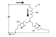
- FIG. 5 is a schematic view showing an example of wiring in the three-phase coil 32.
- the connection in the three-phase coil 32 is, for example, a Y connection.
- the three-phase coil 32 is connected by, for example, a Y connection.
- the internal phase coil 321 and the medium phase coil 322, and the external phase coil 323 are connected by a Y connection.
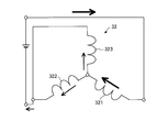
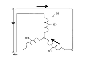
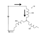
- FIGS. 6 to 11 are diagrams showing an example of a connection pattern of the three-phase coil 32 when magnetizing the unmagnetized magnetic body 22 using the stator 3.
- FIGS. 6 to 11 are diagrams showing an example of a connection state between the three-phase coil 32 connected by the Y connection and the power supply for magnetism.
- the arrows shown in FIGS. 6 to 11 indicate the direction of the current.
- the power source for magnetism is also simply referred to as "power source”. In the present embodiment, the power source is a DC power source.
- the positive side of the power supply (that is, the positive pole side of the power supply) is connected to the medium phase coil 322, and the negative side of the power supply (that is, the negative pole side of the power supply) is the internal phase coil 321. And is connected to the external phase coil 323.
- the connection state shown in FIG. 6 is referred to as a connection pattern P1.
- a large current flows from the power supply to the medium-phase coil 322.
- the current flowing from the power supply to the medium-phase coil 322 is divided into a current flowing through the internal-phase coil 321 and a current flowing through the external-phase coil 323. Therefore, the current flowing through the middle phase coil 322 is larger than the current flowing through the inner phase coil 321 and the current flowing through the outer phase coil 323.
- connection state shown in FIG. 7 is referred to as a connection pattern P2.
- a large current flows from the power supply to the internal phase coil 321.
- the current flowing from the power supply to the internal phase coil 321 is divided into a current flowing through the medium phase coil 322 and a current flowing through the external phase coil 323. Therefore, the current flowing through the inner phase coil 321 is larger than the current flowing through the middle phase coil 322 and the current flowing through the outer phase coil 323.
- connection state shown in FIG. 8 is referred to as a connection pattern P3.
- a large current flows from the power supply to the external phase coil 323.
- the current flowing from the power supply to the outer phase coil 323 is divided into a current flowing through the inner phase coil 321 and a current flowing through the middle phase coil 322. Therefore, the current flowing through the outer phase coil 323 is larger than the current flowing through the inner phase coil 321 and the current flowing through the middle phase coil 322.
- connection state shown in FIG. 9 is referred to as a connection pattern P4.
- a large current flows from the power supply to the medium-phase coil 322.
- the current flowing from the power supply to the middle phase coil 322 flows through the inner phase coil 321 and does not flow through the outer phase coil 323.
- connection state shown in FIG. 10 is referred to as a connection pattern P5.
- a large current flows from the power supply to the internal phase coil 321.
- the current flowing from the power supply to the internal phase coil 321 flows through the external phase coil 323 and does not flow through the medium phase coil 322.
- connection state shown in FIG. 11 is referred to as a connection pattern P6.
- a large current flows from the power supply to the external phase coil 323.
- the current flowing from the power supply to the outer phase coil 323 flows to the middle phase coil 322 and does not flow to the inner phase coil 321.
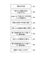
- FIG. 12 is a flowchart showing an example of the manufacturing process of the electric motor 1.
- step S1 the rotor 2 is produced. Specifically, the unmagnetized magnetic body 22 is arranged in each magnet insertion hole 211 of the rotor core 21. In step S1, the shaft 4 may be fixed to the shaft hole 212.
- step S2 the three-phase coil 32 is attached to the stator core 31.
- the three-phase coil 32 is attached to the stator core 31 by distributed winding.
- step S3 the internal phase coil 321 and the medium phase coil 322, and the external phase coil 323 are connected.
- the internal phase coil 321 and the medium phase coil 322, and the external phase coil 323 are connected by a Y connection.
- the internal phase coil 321 and the medium phase coil 322 and the external phase coil 323 may be connected before the three-phase coil 32 is attached to the stator core 31 by distributed winding.
- the internal phase coil 321 and the medium phase coil 322 and the external phase coil 323 connected to each other may be attached to the stator core 31 by distributed winding.
- step S4 the rotor 2 having the unmagnetized magnetic body 22 is arranged inside the stator 3 (specifically, the stator core 31).
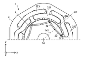
- FIG. 13 is a diagram showing an example of a manufacturing process of the electric motor 1.
- step S4 for example, as shown in FIG. 13, the rotor 2 is placed at a reference position.
- the reference position is a coil in which the center of the magnetizing target magnetic pole of the rotor 2 is connected to the positive side of the power supply with the magnetic pole center line M1 in the xy plane (in the present embodiment, the first phase coil or the second phase). It is a position that coincides with the center of the magnetic pole of the coil).
- the first phase coil is the middle phase coil 322.
- the center of the magnetic poles of the coils of each phase is the center of the magnetic poles formed when a current flows through the three-phase coil 32.
- the center of the magnetic pole of the medium-phase coil 322 is indicated by the magnetic pole center line C1.
- the magnetic pole center line C1 passes through the center of the magnetic pole of the first phase coil formed when a current flows through the three-phase coil 32 and the axis Ax in the xy plane.
- the center of the magnetic pole of the medium-phase coil 322 is the center of the magnetic pole of the medium-phase coil 322 formed when a current flows from the power source to the medium-phase coil 322.
- step S5 the three-phase coil 32 is connected to a power source for magnetizing.
- the connection state between the three-phase coil 32 and the power supply is the first connection state.
- the first connection state is the connection state shown in FIG. 6, the connection state shown in FIG. 7, the connection state shown in FIG. 8, the connection state shown in FIG. 9, the connection state shown in FIG. 10, or the connection state shown in FIG. It is the connection state shown in.
- the coil connected to the positive side of the power supply in the first connection state is referred to as a "first phase coil".
- the medium-phase coil 322 of the three-phase coil 32 is connected to the positive side of the power supply.
- the medium phase coil 322 is referred to as a "first phase coil”.
- the internal phase coil 321 of the three-phase coil 32 is connected to the positive side of the power supply.
- the internal phase coil 321 is referred to as a "first phase coil”.
- the external phase coil 323 of the three-phase coil 32 is connected to the positive side of the power supply.
- the external phase coil 323 is referred to as a "first phase coil”.
- the first connection state is the connection state shown in FIG. 6 or FIG. That is, in the present embodiment, in step S5, the medium phase coil 322 is connected to the positive side of the power supply.
- step S2 to step S5 is not limited to the example shown in FIG. 12, and may be appropriately replaced.
- FIG. 14 is a diagram showing an example of a manufacturing process of the electric motor 1, specifically, a first magnetizing process.
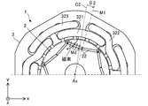
- step S6 the center of the magnetic pole of the rotor 2 having the unmagnetized magnetic body 22 is set at a first angle ⁇ 1 in the first rotation direction of the rotor 2 with respect to the center of the magnetic pole of the coil of the first phase.
- the first phase coil is the middle phase coil 322. That is, a current is passed through the three-phase coil 32 in a state where the center of the magnetic pole of the rotor 2 is rotated by a first angle ⁇ 1 from the reference position in the first rotation direction of the rotor 2.
- a current is passed from the power supply to the three-phase coil 32 (specifically, the first-phase coil).
- the first rotation direction is counterclockwise with respect to the axis Ax.
- the direction of the magnetic flux from the first phase coil is as parallel as possible to the easy magnetization direction on one end side of the magnetic body 22 as the magnetizing target.
- one end side of the magnetic body 22 can be easily magnetized in the direction of easy magnetization without using a large current.
- the first angle ⁇ 1 is such that the direction of the magnetic flux from the first phase coil (medium phase coil 322 in FIG. 14) and the easy magnetization direction of the magnetic body 22 as the magnetizing target are close to parallel. It is desirable to have.
- the first angle ⁇ 1 is an angle at which the direction of the magnetic flux from the first phase coil (medium phase coil 322 in FIG. 14) and the easy magnetization direction of the magnetic body 22 to be magnetized are parallel to each other. Is more desirable.
- the current flowing from the power supply to the first phase coil is the current flowing through the second phase coil and the third phase. It is divided into the current flowing through the coil. That is, the current flows through the coils of each phase, that is, the coil of the first phase, the coil of the second phase, and the coil of the third phase.
- the first angle ⁇ 1 is, for example, 0 degrees ⁇ 1 ⁇ 10 degrees.
- the first connection state is the connection state shown in FIG. 9, FIG. 10, or FIG. 11
- the current flowing from the power supply to the first phase coil is the second phase coil or the third phase coil. And does not flow into either the second phase coil or the third phase coil. That is, the current flows in only two of the three phases and not in one of the three phases.
- the first angle ⁇ 1 is, for example, 2.5 degrees ⁇ ⁇ 1 ⁇ 12.5 degrees.
- the magnetic body 22 to be magnetized is magnetized in the direction Md indicated by the arrow. ..
- the direction Md is the direction in which the magnetic material 22 is easily magnetized. Since the rotor 2 is in a state of being rotated by a first angle ⁇ 1 with respect to the center of the magnetic poles of the first phase coil (the middle phase coil 322 in FIG. 14), the magnetic body 22 is magnetized by the magnetic body 22. It can be easily magnetized in an easy direction. In the present embodiment, the easy magnetization direction of the magnetic body 22 is the lateral direction of the magnetic body 22 in the xy plane.
- the two permanent magnets 22 form one magnetic pole of the rotor 2, but one permanent magnet 22 may form one magnetic pole of the rotor 2.
- the two magnetic bodies 22 shown in FIG. 14 are integrated as one member.
- step S7 the connection of the three-phase coil 32 is switched. Specifically, the connection with the positive side of the power supply is switched from the first phase coil to the second phase coil of the three-phase coil 32.
- the first phase coil is the middle phase coil 322
- the second phase coil is the inner phase coil 321 or the outer phase coil 323.
- the energization path in the three-phase coil 32 is changed.
- step S7 the connection state between the three-phase coil 32 and the power supply is a second connection state different from the first connection state. That is, in step S7, the connection state of the three-phase coil 32 is switched from the first connection state to the second connection state.
- the second connection state is the connection state shown in FIG. 6, the connection state shown in FIG. 7, the connection state shown in FIG. 8, the connection state shown in FIG. 9, the connection state shown in FIG. 10, or the connection state shown in FIG. It is the connection state shown in.
- the coil connected to the positive side of the power supply in the second connection state is referred to as a "second phase coil".
- the second connection state is the connection state shown in FIG. 7. That is, in the present embodiment, the connection with the positive side of the power supply is switched from the medium phase coil 322 to the second phase coil of the three-phase coil 32 (in the present embodiment, the internal phase coil 321) (step S7). ..
- FIG. 15 is a diagram showing an example of a manufacturing process of the electric motor 1, specifically, a second magnetizing process.
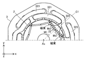
- step S8 the second rotation of the rotor 2 with respect to the center of the magnetic poles of the rotor 2 with respect to the center of the magnetic poles of the second phase coil formed when a current flows from the power source to the second phase coil.
- a current is passed through the three-phase coil 32 in a state of being rotated by a second angle ⁇ 2 in the direction.
- the second phase coil is the internal phase coil 321.
- the second rotation direction is opposite to the first rotation direction.
- a current is passed through the three-phase coil 32 in a state where the center of the magnetic pole of the rotor 2 is rotated by a second angle ⁇ 2 from the reference position in the second rotation direction of the rotor 2.
- a current is passed from the power supply to the three-phase coil 32 (specifically, the second-phase coil).
- the reference position is such that the center of the magnetizing target magnetic pole of the rotor 2 coincides with the center of the magnetic pole of the second phase coil (internal phase coil 321 in FIG. 15) with the magnetic pole center line M1. The position.
- the second rotation direction is clockwise with respect to the axis Ax.
- the second rotation direction may be counterclockwise with respect to the axis Ax.
- the first rotation direction is clockwise.
- the center of the magnetic pole of the internal phase coil 321 is indicated by the magnetic pole center line C2.
- the magnetic pole center line C2 passes through the center of the magnetic poles of the second phase coil formed when a current flows through the three-phase coil 32.
- the center of the magnetic pole of the internal phase coil 321 is the center of the magnetic pole of the internal phase coil 321 formed when a current flows from the power source to the internal phase coil 321.
- the direction of the magnetic flux from the second phase coil is as parallel as possible to the direction of easy magnetization on the other end side of the magnetic body 22 to be magnetized.
- the other end side of the magnetic body 22 can be easily magnetized in the direction of easy magnetization without using a large current.
- the second angle ⁇ 2 is such that the direction of the magnetic flux from the second phase coil (internal phase coil 321 in FIG. 15) and the easy magnetization direction of the magnetic body 22 to be magnetized are close to parallel. It is desirable to have.
- the second angle ⁇ 2 is an angle at which the direction of the magnetic flux from the second phase coil (internal phase coil 321 in FIG. 15) and the easy magnetization direction of the magnetic body 22 to be magnetized are parallel to each other. Is more desirable.
- the current flowing from the power supply to the second phase coil is the current flowing through the first phase coil and the third phase. It is divided into the current flowing through the coil. That is, the current flows through the coils of each phase, that is, the coil of the first phase, the coil of the second phase, and the coil of the third phase.
- the second angle ⁇ 2 is, for example, 0 degrees ⁇ 2 ⁇ 10 degrees.
- the second connection state is the connection state shown in FIG. 9, FIG. 10, or FIG. 11
- the current flowing from the power supply to the second phase coil is the first phase coil or the third phase coil. And does not flow into either the first phase coil or the third phase coil. That is, the current flows in only two of the three phases and not in one of the three phases.
- the second angle ⁇ 2 is, for example, 2.5 degrees ⁇ ⁇ 1 ⁇ 12.5 degrees.
- the magnetic body 22 to be magnetized is magnetized in the direction Md indicated by the arrow. .. Since the rotor 2 is in a state of being rotated by a second angle ⁇ 2 with respect to the center of the magnetic pole of the second phase coil (internal phase coil 321 in FIG. 15), the magnetic body 22 is magnetized by the magnetic body 22. It can be easily magnetized in an easy direction.
- step S9 the three-phase coil 32 is removed from the power supply. As a result, the electric motor 1 is obtained.
- the first phase coil is the middle phase coil 322, the second phase coil is the inner phase coil 321 and the third phase coil is the outer phase coil 323, but the first phase coil is the middle phase coil.
- the phase coil 322 is not limited, the second phase coil is not limited to the internal phase coil 321 and the third phase coil is not limited to the external phase coil 323.
- the first phase coil may be the internal phase coil 321, the second phase coil may be the middle phase coil 322, and the third phase coil may be the external phase coil 323.
- FIG. 16 is a diagram showing another example of the stator 3.
- the number of coils in the first phase is the same as the number of magnetic poles in the rotor 2
- the number of coils in the second phase is the same as the number of magnetic poles in the rotor 2.
- the number of coils in the third phase is the same as the number of magnetic poles in the rotor 2. That is, the three-phase coil 32 has six internal-phase coils 321 and six medium-phase coils 322, and six external-phase coils 323.
- the coils of each phase of the three-phase coil 32 have an annular shape. That is, in the coil end 32a of the three-phase coil 32, the six internal phase coils 321 have an annular shape, the six medium phase coils 322 have an annular shape, and the six external phase coils 323 have an annular shape. have.
- the coils of each phase of the three-phase coil 32 are arranged concentrically. That is, in the coil end 32a of the three-phase coil 32, the six internal phase coils 321 are arranged concentrically, the six medium phase coils 322 are arranged concentrically, and the six external phase coils 323. Are arranged concentrically.
- Coil of the same phase adjacent to each other is arranged in each slot 311.
- the coil of the first phase is located outside the coil of the second phase in the radial direction of the stator core 31, and the coil of the third phase is the coil of the first phase. It is located on the outside of the coil.
- the first phase coil is the middle phase coil 322
- the second phase coil is the inner phase coil 321
- the third phase coil is the outer phase coil 323.
- the second-phase coil may be located outside the first-phase coil, and the third-phase coil may be the second-phase coil. It may be located outside the.
- the stator 3 shown in FIG. 16 is applicable to the above-mentioned electric motor 1.
- the method for manufacturing the electric motor 1 having the stator 3 shown in FIG. 16 is the same as the method described in the above-mentioned ⁇ Method for manufacturing the electric motor 1>.
- FIG. 17 is a diagram showing a magnetizing process in an electric motor as a comparative example.
- the angle with respect to the reference position is zero in the magnetizing step.
- the direction of the magnetic flux from the three-phase coil (medium-phase coil 322 in FIG. 17) is close to a right angle to the easy magnetization direction of the magnetic body 22 as the magnetizing target. Therefore, in the example shown in FIG. 17, it is difficult to magnetize both sides of the magnetic body 22 in the xy plane in the direction of easy magnetization.
- each magnetic pole of the rotor 2 is magnetized twice. Specifically, for each magnetic pole of the rotor 2, the first magnetization is performed in a state where the center of the magnetic pole of the rotor 2 is rotated by a first angle ⁇ 1 with respect to the center of the magnetic poles of the first phase coil. Do. As a result, the magnetic body 22 can be magnetized in a state where the direction of the magnetic flux from the coil of the first phase is as parallel as possible to the direction of easy magnetization on one end side of the magnetic body 22 to be magnetized. In particular, one end side of the magnetic body 22 in the xy plane is easily magnetized in the direction of easy magnetization.
- the center of the magnetic pole of the rotor 2 is rotated by a second angle ⁇ 2 in the second rotation direction R2 of the rotor 2 with respect to the center of the magnetic poles of the second phase coil.
- the second magnetization is performed in the second connection state.
- the magnetic body 22 can be magnetized in a state where the direction of the magnetic flux from the coil of the second phase is as parallel as possible to the direction of easy magnetization on the other end side of the magnetic body 22 to be magnetized.
- the magnetic material 22 can be easily magnetized in the direction of easy magnetization without using a large current.
- the other end side of the magnetic body 22 in the xy plane is easily magnetized in the direction of easy magnetization. Therefore, the magnetizing current can be reduced as compared with the example shown in FIG.
- the magnetic body 22 can be easily magnetized in the direction of easy magnetization, the magnetic force of the rotor 2 can be increased. As a result, it is possible to provide a highly efficient electric motor 1.
- the magnetizing target magnetic pole of the rotor 2 is magnetized twice, a large force is generated in the three-phase coil 32, and the three-phase coil is compared with the example shown in FIG. The coil end 32a of 32 is easily deformed.
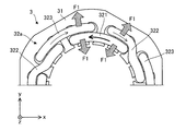
- FIG. 18 shows the radial electromagnetic force F1 generated at the coil end 32a of the three-phase coil 32 when the three-phase coil 32 is energized in the manufacturing process of the electric motor 1, specifically, the magnetizing process of the magnetic body 22. It is a figure which shows an example.
- the arrow shown on the three-phase coil 32 indicates the direction of the current.
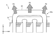
- FIG. 19 shows the axial electromagnetic force F2 generated at the coil end 32a of the three-phase coil 32 when the three-phase coil 32 is energized in the manufacturing process of the electric motor 1, specifically, the magnetizing process of the magnetic body 22. It is a figure which shows an example.
- an electromagnetic force F1 in the radial direction that repels each other is generated between the internal phase coil 321 and the medium phase coil 322.
- An electromagnetic force F1 in the radial direction that repels each other is generated between the internal phase coil 321 and the external phase coil 323.
- an axial electromagnetic force F2 is generated in the three-phase coil 32.
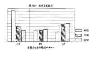
- FIG. 20 is a graph showing the difference in the magnitude of the electromagnetic force F1 in the radial direction for each connection pattern in the three-phase coil 32 when the three-phase coil 32 is energized in the magnetizing step of the magnetic body 22.
- the data shown in FIG. 20 is the result of analysis by electromagnetic field analysis.
- the connection patterns P1, P2, and P3 correspond to the connection patterns shown in FIGS. 6 to 8, respectively.
- connection pattern P3 a large current flows from the magnetizing power supply to the outer phase coil 323, and the current flowing through the outer phase coil 323 is larger than the current flowing through the inner phase coil 321 and the current flowing through the middle phase coil 322.
- the electromagnetic force F1 generated in the external phase coil 323 is much larger than the electromagnetic force F1 generated in the other coils.
- the external phase coil 323 is easily deformed in the radial direction.
- the electric motor 1 is applied to the compressor, the external phase coil 323 approaches a metal part (for example, a closed container of the compressor), and it is difficult to secure the electrical insulation of the external phase coil 323.
- connection pattern P1 a large current flows from the magnetizing power supply to the medium-phase coil 322, and the current flowing through the medium-phase coil 322 is the current flowing through the internal-phase coil 321 and the current flowing through the external-phase coil 323. Greater than each.
- connection pattern P1 there is no big difference in the electromagnetic force F1 generated in the coils of each phase.
- the electromagnetic force F1 generated in the external phase coil 323 is smaller than the electromagnetic force F1 generated in the other coils.
- connection pattern P2 a large current flows from the magnetizing power supply to the internal phase coil 321 and the current flowing through the internal phase coil 321 is larger than the current flowing through the medium phase coil 322 and the current flowing through the external phase coil 323.
- the electromagnetic force F1 generated in the external phase coil 323 is smaller than the electromagnetic force F1 generated in the other coils.
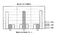
- FIG. 21 is a graph showing the difference in the magnitude of the electromagnetic force F2 in the axial direction for each connection pattern in the three-phase coil 32 when the three-phase coil 32 is energized in the magnetizing step of the magnetic body 22.
- the connection patterns P1, P2, and P3 correspond to the connection patterns P1, P2, and P3 in FIG. 20, respectively.
- a large electromagnetic force F2 is generated in one of the three-phase coils 32 regardless of the connection pattern.
- a large current flows from the power source to the external phase coil 323, and a large electromagnetic force F2 in the axial direction is generated in the external phase coil 323.
- a large current flows from the power source to the medium-phase coil 322, and a large electromagnetic force F2 in the axial direction is generated in the medium-phase coil 322.
- a large current flows from the power source to the internal phase coil 321 and a large electromagnetic force F2 in the axial direction is generated in the internal phase coil 321.
- the first connection state is the connection pattern P1 or P2
- the second connection state is preferably the connection pattern P1 or P2. That is, when the first connection state is the connection pattern P1, the second connection state is the connection pattern P2. When the second connection state is the connection pattern P2, the second connection state is the connection pattern P1.
- FIG. 22 is a graph showing the relationship between the angle [degrees] with respect to the reference position in the connection pattern P1 or P2 and the current value [kAT] from the power source for magnetizing.
- the angle with respect to the reference position corresponds to the above-mentioned first angle ⁇ 1 and second angle ⁇ 2.
- the current value from the magnetizing power supply is 278 [kAT].
- the first connection state and the second connection state are the connection patterns P1 or P2
- the first angle ⁇ 1 and the second angle ⁇ 2 are 0 degrees ⁇ 1 ⁇ . 10 degrees, 0 degrees ⁇ 2 ⁇ 10 degrees.
- the current from the magnetizing power source can be reduced as compared with the conventional magnetizing method. It is more desirable that the first angle ⁇ 1 and the second angle ⁇ 2 are 2.5 degrees ⁇ ⁇ 1 ⁇ 10 degrees and 2.5 degrees ⁇ ⁇ 2 ⁇ 10 degrees.
- the first angle ⁇ 1 is 2.5 degrees ⁇ ⁇ 1 ⁇ 7.5 degrees or 5 degrees ⁇ ⁇ 1 ⁇ 10 degrees.
- the first angle ⁇ 1 and the second angle ⁇ 2 are most preferably 5 degrees. In this case, the current value is reduced by about 20.5% as compared with the conventional magnetizing method.
- FIG. 23 is a graph showing the difference in the magnitude of the electromagnetic force F1 in the radial direction for each connection pattern in the three-phase coil 32 when the three-phase coil 32 is energized in the magnetizing step of the magnetic body 22.
- the data shown in FIG. 23 is the result of analysis by electromagnetic field analysis.
- the connection patterns P4, P5, and P6 correspond to the connection patterns shown in FIGS. 9 to 11, respectively.
- connection pattern P6 a large current flows from the magnetizing power supply to the external phase coil 323.
- the electromagnetic force F1 generated in the external phase coil 323 is much larger than the electromagnetic force F1 generated in the other coils.
- the external phase coil 323 is easily deformed in the radial direction.
- the electric motor 1 is applied to the compressor, the external phase coil 323 approaches a metal part (for example, a closed container of the compressor), and it is difficult to secure the electrical insulation of the external phase coil 323.
- connection pattern P4 a large current flows from the magnetizing power supply to the medium-phase coil 322.
- connection pattern P4 there is no big difference in the electromagnetic force F1 generated in the coils of each phase through which the current flows.
- the electromagnetic force F1 is not generated in the external phase coil 323.
- the deformation of the external phase coil 323 is suppressed, the electrical insulation property of the external phase coil 323 can be ensured.
- FIG. 24 is a graph showing the difference in the magnitude of the electromagnetic force F2 in the axial direction for each connection pattern in the three-phase coil 32 when the three-phase coil 32 is energized in the magnetizing step of the magnetic body 22.
- the connection patterns P4, P5, and P6 correspond to the connection patterns P4, P5, and P6 in FIG. 23, respectively.
- the first connection state is the connection pattern P4 or P5
- the second connection state is preferably the connection pattern P4 or P5. That is, when the first connection state is the connection pattern P4, the second connection state is the connection pattern P5. When the second connection state is the connection pattern P5, the second connection state is the connection pattern P4.
- FIG. 25 is a graph showing the relationship between the angle [degrees] with respect to the reference position in the connection pattern P4 or P5 and the current value [kAT] from the power source for magnetizing.
- the angle with respect to the reference position corresponds to the above-mentioned first angle ⁇ 1 and second angle ⁇ 2.
- the current value from the magnetizing power supply is 450 [kAT].
- the first connection state and the second connection state are the connection patterns P4 or P5
- the first angle ⁇ 1 and the second angle ⁇ 2 are 0 degrees ⁇ 1 ⁇ . It is 12.5 degrees and 0 degrees ⁇ 2 ⁇ 12.5 degrees.
- the current from the magnetizing power source can be reduced as compared with the conventional magnetizing method. It is more desirable that the first angle ⁇ 1 and the second angle ⁇ 2 are 2.5 degrees ⁇ ⁇ 1 ⁇ 12.5 degrees and 2.5 degrees ⁇ ⁇ 2 ⁇ 12.5 degrees.
- first angle ⁇ 1 and the second angle ⁇ 2 are 5 degrees ⁇ ⁇ 1 ⁇ 12.5 degrees, 5 degrees ⁇ ⁇ 2 ⁇ 12.5 degrees.
- the first angle ⁇ 1 and the second angle ⁇ 2 are more preferably 5 degrees ⁇ ⁇ 1 ⁇ 10 degrees, 5 degrees ⁇ ⁇ 2 ⁇ 10 degrees.
- the first angle ⁇ 1 and the second angle ⁇ 2 are most preferably 7.5 degrees. In this case, the current value is reduced by 53.3% as compared with the conventional magnetizing method.
- connection pattern P4 or P5 the current from the magnetizing power source can be reduced to 210 [kAT]. Therefore, in the connection pattern P4 or P5, the current from the magnetizing power source can be reduced as compared with the minimum value 221 [kAT] in the connection pattern P1 or P2.
- FIG. 26 shows a difference in the magnitude of the electromagnetic force F1 in the radial direction for each connection pattern in the three-phase coil 32 when the three-phase coil 32 is energized in the magnetizing step of the magnetic body 22 of the modified example shown in FIG. It is a graph which shows.
- the data shown in FIG. 26 is the result of analysis by electromagnetic field analysis.
- the connection patterns P1, P2, and P3 correspond to the connection patterns shown in FIGS. 6 to 8, respectively.
- FIG. 27 shows a difference in the magnitude of the electromagnetic force F2 in the axial direction for each connection pattern in the three-phase coil 32 when the three-phase coil 32 is energized in the magnetizing step of the magnetic body 22 of the modified example shown in FIG. It is a graph which shows.
- the connection patterns P1, P2, and P3 correspond to the connection patterns P1, P2, and P3 in FIG. 26, respectively.
- the first connection state is the connection pattern P1 or P2, and similarly.
- the second connection state is preferably the connection pattern P1 or P2.
- FIG. 28 shows a difference in the magnitude of the electromagnetic force F1 in the radial direction for each connection pattern in the three-phase coil 32 when the three-phase coil 32 is energized in the magnetizing step of the magnetic body 22 of the modified example shown in FIG. It is a graph which shows.
- the data shown in FIG. 28 is the result of analysis by electromagnetic field analysis.
- the connection patterns P4, P5, and P6 correspond to the connection patterns shown in FIGS. 9 to 11, respectively.
- FIG. 29 shows a difference in the magnitude of the electromagnetic force F2 in the axial direction for each connection pattern in the three-phase coil 32 when the three-phase coil 32 is energized in the magnetizing step of the magnetic body 22 of the modified example shown in FIG. It is a graph which shows.
- the connection patterns P4, P5, and P6 correspond to the connection patterns P4, P5, and P6 in FIG. 28, respectively.
- the first connection state is the connection pattern P4 or P5, and similarly.
- the second connection state is preferably a connection pattern P4 or P5.
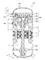
- FIG. 30 is a cross-sectional view schematically showing the structure of the compressor 300.
- the compressor 300 has an electric motor 1 as an electric element, a closed container 307 as a housing, and a compression mechanism 305 as a compression element (also referred to as a compression device).
- the compressor 300 is a scroll compressor.
- the compressor 300 is not limited to the scroll compressor.
- the compressor 300 may be a compressor other than the scroll compressor, for example, a rotary compressor.
- the electric motor 1 in the compressor 300 is the electric motor 1 described in the first embodiment.
- the electric motor 1 drives the compression mechanism 305.
- the compressor 300 further includes a subframe 308 that supports the lower end of the shaft 4 (that is, the end opposite to the compression mechanism 305 side).
- the compression mechanism 305 is arranged in the closed container 307.
- the compression mechanism 305 includes a fixed scroll 301 having a spiral portion, a swing scroll 302 having a spiral portion that forms a compression chamber between the spiral portion of the fixed scroll 301, and a compliance frame 303 that holds the upper end portion of the shaft 4. And a guide frame 304 which is fixed to the closed container 307 and holds the compliance frame 303.
- a suction pipe 310 penetrating the closed container 307 is press-fitted into the fixed scroll 301. Further, the closed container 307 is provided with a discharge pipe 306 for discharging the high-pressure refrigerant gas discharged from the fixed scroll 301 to the outside.
- the discharge pipe 306 communicates with an opening provided between the compression mechanism 305 of the closed container 307 and the electric motor 1.
- the electric motor 1 is fixed to the closed container 307 by fitting the stator 3 into the closed container 307.
- the configuration of the electric motor 1 is as described above.
- a glass terminal 309 that supplies electric power to the electric motor 1 is fixed to the closed container 307 by welding.
- the compressor 300 Since the compressor 300 has the electric motor 1 described in the first embodiment, it has the advantages described in the first embodiment.
- the compressor 300 has the electric motor 1 described in the first embodiment, it is possible to provide the compressor 300 with high efficiency.
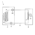
- FIG. 31 is a diagram schematically showing the configuration of the refrigerating air conditioner 7 according to the third embodiment.
- the refrigerating and air-conditioning device 7 can be operated for heating and cooling, for example.
- the refrigerant circuit diagram shown in FIG. 31 is an example of a refrigerant circuit diagram of an air conditioner capable of cooling operation.
- the refrigerating and air-conditioning device 7 has an outdoor unit 71, an indoor unit 72, and a refrigerant pipe 73 connecting the outdoor unit 71 and the indoor unit 72.
- the outdoor unit 71 includes a compressor 300, a condenser 74 as a heat exchanger, a throttle device 75, and an outdoor blower 76 (first blower).
- the condenser 74 condenses the refrigerant compressed by the compressor 300.
- the throttle device 75 decompresses the refrigerant condensed by the condenser 74 and adjusts the flow rate of the refrigerant.
- the diaphragm device 75 is also called a decompression device.
- the indoor unit 72 has an evaporator 77 as a heat exchanger and an indoor blower 78 (second blower).
- the evaporator 77 evaporates the refrigerant decompressed by the throttle device 75 to cool the indoor air.
- the refrigerant is compressed by the compressor 300 and flows into the condenser 74.
- the refrigerant is condensed by the condenser 74, and the condensed refrigerant flows into the drawing device 75.
- the refrigerant is decompressed by the throttle device 75, and the decompressed refrigerant flows into the evaporator 77.
- the refrigerant evaporates in the evaporator 77, and the refrigerant (specifically, the refrigerant gas) flows into the compressor 300 of the outdoor unit 71 again.
- the configuration and operation of the refrigerating air conditioner 7 described above is an example, and is not limited to the above-mentioned example.
- the refrigerating air conditioner 7 according to the third embodiment, it has the advantages described in the first and second embodiments.
- the refrigerating and air-conditioning device 7 according to the third embodiment has the compressor 300 according to the second embodiment, it is possible to provide a highly efficient refrigerating and air-conditioning device 7.
Landscapes
- Engineering & Computer Science (AREA)
- Manufacturing & Machinery (AREA)
- Power Engineering (AREA)
- Windings For Motors And Generators (AREA)
- Manufacture Of Motors, Generators (AREA)
- Permanent Field Magnets Of Synchronous Machinery (AREA)
- Permanent Magnet Type Synchronous Machine (AREA)
Abstract
Description
固定子鉄心及び前記固定子鉄心に分布巻きで取り付けられた3相コイルを持つ固定子と、磁極を持ち、前記固定子の内側に配置された回転子とを有する電動機の製造方法であって、
着磁されていない磁性体を持つ前記回転子を前記固定子の内側に配置することと、
前記3相コイルの第1相のコイルを、着磁用の電源のプラス側に接続することと、
前記回転子の前記磁極の中心を、前記電源から前記第1相のコイルに電流が流れたときに形成される前記第1相のコイルの磁極の中心に対して前記回転子の第1の回転方向に第1の角度回転させた状態で、前記3相コイルに電流を通すことと、
前記電源の前記プラス側との接続を、前記第1相のコイルから前記3相コイルの第2相のコイルに切り替えることと、
前記回転子の前記磁極の中心を、前記電源から前記第2相のコイルに電流が流れたときに形成される前記第2相のコイルの磁極の中心に対して前記回転子の第1の回転方向とは反対方向である第2の回転方向に第2の角度回転させた状態で、前記3相コイルに電流を通すことと
を備える。
本発明の他の態様に係る電動機は、
固定子鉄心及び前記固定子鉄心に分布巻きで取り付けられた3相コイルを持つ固定子と、
磁極を持ち、前記固定子の内側に配置された回転子と
を備え、
前記回転子は、
固定子鉄心と、
前記固定子鉄心に配置された永久磁石と
を有し、
前記回転子の軸方向と直交する平面において、前記永久磁石の一端側は、前記回転子の前記磁極の中心を、前記電源から前記3相コイルの第1相のコイルに電流が流れたときに形成される前記第1相のコイルの磁極の中心に対して前記回転子の第1の回転方向に第1の角度回転させた状態で、前記3相コイルに電流を通すことにより着磁されており、
前記回転子の軸方向と直交する前記平面において、前記永久磁石のもう一端側は、前記回転子の前記磁極の中心を、前記電源から前記3相コイルの第2相のコイルに電流が流れたときに形成される前記第2相のコイルの磁極の中心に対して前記回転子の第1の回転方向とは反対方向である第2の回転方向に第2の角度回転させた状態で、前記3相コイルに電流を通すことにより着磁されている。
本発明の他の態様に係る圧縮機は、
密閉容器と、
前記密閉容器内に配置された圧縮装置と、
前記圧縮装置を駆動する前記電動機と
を備える。
本発明の他の態様に係る空気調和機は、
前記圧縮機と、
熱交換器と
を備える。
各図に示されるxyz直交座標系において、z軸方向(z軸)は、電動機1の軸線Axと平行な方向を示し、x軸方向(x軸)は、z軸方向(z軸)に直交する方向を示し、y軸方向(y軸)は、z軸方向及びx軸方向の両方に直交する方向を示す。軸線Axは、固定子3の中心であり、回転子2の回転中心でもある。軸線Axと平行な方向は、「回転子2の軸方向」又は単に「軸方向」ともいう。径方向は、回転子2又は固定子3の半径方向であり、軸線Axと直交する方向である。xy平面は、軸方向と直交する平面である。矢印D1は、軸線Axを中心とする周方向を示す。回転子2又は固定子3の周方向を、単に「周方向」ともいう。
図1は、本発明の実施の形態1に係る電動機1の構造を概略的に示す平面図である。
回転子2は、固定子3の内側に回転可能に配置されている。回転子2は、回転子鉄心21と、磁性体である少なくとも1つの永久磁石22とを有する。回転子2と固定子3との間には、エアギャップが存在する。回転子2は、軸線Axを中心として回転する。
図3は、固定子3の一例を示す平面図である。
図4は、図3に示される固定子3の内部構造を概略的に示す図である。
3相コイル32における結線は、例えば、Y結線である。言い換えると、3相コイル32は、例えば、Y結線で接続されている。この場合、内相コイル321、中相コイル322、及び外相コイル323は、Y結線で接続されている。
固定子3の製造方法の一例について説明する。
図12は、電動機1の製造工程の一例を示すフローチャートである。
ステップS4において、例えば、図13に示されるように、回転子2を基準位置に配置する。基準位置は、xy平面において、回転子2の着磁対象磁極の中心が、磁極中心線M1が電源のプラス側に接続されたコイル(本実施の形態では、第1相のコイル又は第2相のコイル)の磁極の中心と一致する位置である。
ステップS6では、着磁されていない磁性体22を持つ回転子2の磁極の中心を、第1相のコイルの磁極の中心に対して回転子2の第1の回転方向に第1の角度θ1回転させた状態で、3相コイル32に電流を通す。図14に示される例では、第1相のコイルは、中相コイル322である。すなわち、回転子2の磁極の中心を、基準位置から回転子2の第1の回転方向に第1の角度θ1回転させた状態で、3相コイル32に電流を通す。言い換えると、第1の結線状態において、電源から3相コイル32(具体的には、第1相のコイル)に電流を通す。本実施の形態では、第1の回転方向は、軸線Axについて反時計回りである。
ステップS8では、回転子2の磁極の中心を、電源から第2相のコイルに電流が流れたときに形成される第2相のコイルの磁極の中心に対して回転子2の第2の回転方向に第2の角度θ2回転させた状態で、3相コイル32に電流を通す。図15に示される例では、第2相のコイルは、内相コイル321である。第2の回転方向は、第1の回転方向とは反対方向である。すなわち、回転子2の磁極の中心を、基準位置から回転子2の第2の回転方向に第2の角度θ2回転させた状態で、3相コイル32に電流を通す。言い換えると、第2の結線状態において、電源から3相コイル32(具体的には、第2相のコイル)に電流を通す。
図16は、固定子3の他の例を示す図である。
図16に示される固定子3では、第1相のコイルの数は、回転子2の磁極数と同じであり、第2相のコイルの数は、回転子2の磁極数と同じであり、第3相のコイルの数は、回転子2の磁極数と同じである。すなわち、3相コイル32は、6個の内相コイル321、6個の中相コイル322、及び6個の外相コイル323を持っている。
電動機1の製造方法の利点を説明する。
図17は、比較例としての電動機における着磁工程を示す図である。
図17に示される例では、着磁工程において、基準位置に対する角度がゼロである。この場合、3相コイル(図17では、中相コイル322)からの磁束の向きは、着磁対象としての磁性体22の磁化容易方向に対して直角に近い。したがって、図17に示される例では、xy平面における磁性体22の両側を磁化容易方向に着磁させることが困難である。
図19は、電動機1の製造工程、具体的には、磁性体22の着磁工程において、3相コイル32に通電したとき、3相コイル32のコイルエンド32aに生じる軸方向における電磁力F2の例を示す図である。
本発明の実施の形態2に係る圧縮機300について説明する。
図30は、圧縮機300の構造を概略的に示す断面図である。
本発明の実施の形態3に係る圧縮機300を有する、空気調和機としての冷凍空調装置7について説明する。
図31は、実施の形態3に係る冷凍空調装置7の構成を概略的に示す図である。
Claims (15)
- 固定子鉄心及び前記固定子鉄心に分布巻きで取り付けられた3相コイルを持つ固定子と、磁極を持ち、前記固定子の内側に配置された回転子とを有する電動機の製造方法であって、
着磁されていない磁性体を持つ前記回転子を前記固定子の内側に配置することと、
前記3相コイルの第1相のコイルを、着磁用の電源のプラス側に接続することと、
前記回転子の前記磁極の中心を、前記電源から前記第1相のコイルに電流が流れたときに形成される前記第1相のコイルの磁極の中心に対して前記回転子の第1の回転方向に第1の角度回転させた状態で、前記3相コイルに電流を通すことと、
前記電源の前記プラス側との接続を、前記第1相のコイルから前記3相コイルの第2相のコイルに切り替えることと、
前記回転子の前記磁極の中心を、前記電源から前記第2相のコイルに電流が流れたときに形成される前記第2相のコイルの磁極の中心に対して前記回転子の第1の回転方向とは反対方向である第2の回転方向に第2の角度回転させた状態で、前記3相コイルに電流を通すことと
を備えた電動機の製造方法。 - 前記3相コイルは、前記第1相のコイル、前記第2相のコイル、及び第3相のコイルを含み、
前記3相コイルのコイルエンドにおいて、前記第1相のコイル、前記第2相のコイル、及び前記第3相のコイルは、前記固定子鉄心の周方向においてこの順に配列されており、
前記コイルエンドにおいて、前記第2相のコイルは、前記第3相のコイルに比べて前記固定子鉄心の中心の近くに位置している
請求項1に記載の電動機の製造方法。 - 前記3相コイルは、前記第1相のコイル、前記第2相のコイル、及び第3相のコイルを含み、
前記3相コイルのコイルエンドにおいて、前記第2相のコイル、前記第1相のコイル、及び前記第3相のコイルは、前記固定子鉄心の周方向においてこの順に配列されており、
前記コイルエンドにおいて、前記第1相のコイルは、前記第3相のコイルに比べて前記固定子鉄心の中心の近くに位置している
請求項1に記載の電動機の製造方法。 - 前記3相コイルは、前記第1相のコイル、前記第2相のコイル、及び第3相のコイルを含み、
前記第1相のコイルが前記電源のプラス側に接続されているとき、前記電源から前記第1相のコイルに流れる電流は、前記第2相のコイルに流れる電流及び前記第3相のコイルに流れる電流に分かれ、
前記第2相のコイルが前記電源のプラス側に接続されているとき、前記電源から前記第2相のコイルに流れる電流は、前記第1相のコイルに流れる電流及び前記第3相のコイルに流れる電流に分かれる
請求項1から3のいずれか1項に記載の電動機の製造方法。 - 前記第1の角度をθ1とし、前記第2の角度をθ2としたとき、
前記第1の角度θ1は、0度<θ1≦10度であり、
前記第2の角度θ2は、0度<θ2≦10度である
請求項4に記載の電動機の製造方法。 - 前記3相コイルは、前記第1相のコイル、前記第2相のコイル、及び第3相のコイルを含み、
前記第1相のコイルが前記電源のプラス側に接続されているとき、前記電源から前記第1相のコイルに流れる電流は、前記第2相のコイル又は前記第3相のコイルに流れ、前記第2相のコイル又は前記第3相のコイルの一方には流れず、
前記第2相のコイルが前記電源のプラス側に接続されているとき、前記電源から前記第2相のコイルに流れる電流は、前記第1相のコイル又は前記第3相のコイルに流れ、前記第1相のコイル又は前記第3相のコイルの一方には流れない
請求項1から3のいずれか1項に記載の電動機の製造方法。 - 前記第1の角度をθ1とし、前記第2の角度をθ2としたとき、
前記第1の角度θ1は、0度<θ1≦12.5度であり、
前記第2の角度θ2は、0度<θ2≦12.5度である
請求項6に記載の電動機の製造方法。 - 前記3相コイルは、前記第1相のコイル、前記第2相のコイル、及び第3相のコイルを含み、
前記第1相のコイルの数は、前記回転子の磁極数と同じであり、
前記第2相のコイルの数は、前記回転子の磁極数と同じであり、
前記第3相のコイルの数は、前記回転子の磁極数と同じである
請求項1に記載の電動機の製造方法。 - 前記3相コイルのコイルエンドにおいて、前記3相コイルの各相のコイルは、同心円状に配列されている請求項8に記載の電動機の製造方法。
- 前記3相コイルのコイルエンドにおいて、前記固定子鉄心の径方向において、前記第1相のコイルは前記第2相のコイルの外側に位置しており、前記第3相のコイルは前記第1相のコイルの外側に位置している請求項8又は9に記載の電動機の製造方法。
- 前記3相コイルのコイルエンドにおいて、前記固定子鉄心の径方向において、前記第2相のコイルは前記第1相のコイルの外側に位置しており、前記第3相のコイルは前記第2相のコイルの外側に位置している請求項8又は9に記載の電動機の製造方法。
- 前記3相コイルは、Y結線で接続されている請求項1から11のいずれか1項に記載の電動機の製造方法。
- 固定子鉄心及び前記固定子鉄心に分布巻きで取り付けられた3相コイルを持つ固定子と、
磁極を持ち、前記固定子の内側に配置された回転子と
を備え、
前記回転子は、
固定子鉄心と、
前記固定子鉄心に配置された永久磁石と
を有し、
前記回転子の軸方向と直交する平面において、前記永久磁石の一端側は、前記回転子の前記磁極の中心を、着磁用の電源から前記3相コイルの第1相のコイルに電流が流れたときに形成される前記第1相のコイルの磁極の中心に対して前記回転子の第1の回転方向に第1の角度回転させた状態で、前記3相コイルに電流を通すことにより着磁されており、
前記回転子の軸方向と直交する前記平面において、前記永久磁石のもう一端側は、前記回転子の前記磁極の中心を、前記電源から前記3相コイルの第2相のコイルに電流が流れたときに形成される前記第2相のコイルの磁極の中心に対して前記回転子の第1の回転方向とは反対方向である第2の回転方向に第2の角度回転させた状態で、前記3相コイルに電流を通すことにより着磁されている
電動機。 - 密閉容器と、
前記密閉容器内に配置された圧縮装置と、
前記圧縮装置を駆動する請求項13に記載の電動機と
を備える圧縮機。 - 請求項14に記載の圧縮機と、
熱交換器と
を備える空気調和機。
Priority Applications (6)
| Application Number | Priority Date | Filing Date | Title |
|---|---|---|---|
| PCT/JP2019/020673 WO2020240617A1 (ja) | 2019-05-24 | 2019-05-24 | 電動機の製造方法、電動機、圧縮機、及び空気調和機 |
| JP2021523145A JP7058802B2 (ja) | 2019-05-24 | 2019-05-24 | 電動機の製造方法、電動機、圧縮機、及び空気調和機 |
| CN201980096341.4A CN113841323A (zh) | 2019-05-24 | 2019-05-24 | 电动机的制造方法、电动机、压缩机以及空调机 |
| AU2019448505A AU2019448505B2 (en) | 2019-05-24 | 2019-05-24 | Method for producing electric motor, electric motor, compressor and air conditioner |
| EP19930472.6A EP3979473A4 (en) | 2019-05-24 | 2019-05-24 | METHOD OF MANUFACTURING AN ELECTRIC MOTOR, ELECTRIC MOTOR, COMPRESSOR, AND AIR CONDITIONER |
| US17/603,212 US20220190697A1 (en) | 2019-05-24 | 2019-05-24 | Method for producing electric motor, electric motor, compressor, and air conditioner |
Applications Claiming Priority (1)
| Application Number | Priority Date | Filing Date | Title |
|---|---|---|---|
| PCT/JP2019/020673 WO2020240617A1 (ja) | 2019-05-24 | 2019-05-24 | 電動機の製造方法、電動機、圧縮機、及び空気調和機 |
Publications (1)
| Publication Number | Publication Date |
|---|---|
| WO2020240617A1 true WO2020240617A1 (ja) | 2020-12-03 |
Family
ID=73553114
Family Applications (1)
| Application Number | Title | Priority Date | Filing Date |
|---|---|---|---|
| PCT/JP2019/020673 Ceased WO2020240617A1 (ja) | 2019-05-24 | 2019-05-24 | 電動機の製造方法、電動機、圧縮機、及び空気調和機 |
Country Status (6)
| Country | Link |
|---|---|
| US (1) | US20220190697A1 (ja) |
| EP (1) | EP3979473A4 (ja) |
| JP (1) | JP7058802B2 (ja) |
| CN (1) | CN113841323A (ja) |
| AU (1) | AU2019448505B2 (ja) |
| WO (1) | WO2020240617A1 (ja) |
Cited By (4)
| Publication number | Priority date | Publication date | Assignee | Title |
|---|---|---|---|---|
| WO2022219675A1 (ja) * | 2021-04-12 | 2022-10-20 | 三菱電機株式会社 | 電動機、圧縮機、冷凍サイクル装置、着磁方法および着磁装置 |
| WO2023021588A1 (ja) * | 2021-08-18 | 2023-02-23 | 三菱電機株式会社 | 着磁方法、着磁装置、電動機、圧縮機および冷凍サイクル装置 |
| WO2023112076A1 (ja) * | 2021-12-13 | 2023-06-22 | 三菱電機株式会社 | 電動機、圧縮機、及び空気調和機 |
| WO2023119455A1 (ja) * | 2021-12-21 | 2023-06-29 | 三菱電機株式会社 | 着磁方法、電動機、圧縮機および冷凍サイクル装置 |
Citations (3)
| Publication number | Priority date | Publication date | Assignee | Title |
|---|---|---|---|---|
| JP2015091192A (ja) | 2013-11-06 | 2015-05-11 | 三星電子株式会社Samsung Electronics Co.,Ltd. | モータ |
| WO2016129330A1 (ja) * | 2015-02-10 | 2016-08-18 | 三菱電機株式会社 | 回転電機、エレベータ用巻上機、および回転電機の永久磁石の着磁および脱磁方法 |
| WO2017046954A1 (ja) * | 2015-09-18 | 2017-03-23 | 三菱電機株式会社 | 回転電機の製造方法、回転電機のステータ、及びそのステータを備える回転電機 |
Family Cites Families (12)
| Publication number | Priority date | Publication date | Assignee | Title |
|---|---|---|---|---|
| JPS57186976A (en) * | 1981-05-08 | 1982-11-17 | Nippon Densan Kk | Brushless motor |
| SE9000497L (sv) * | 1990-02-12 | 1991-08-13 | Ragnar Joensson | Foerfarande och apparat foer reglering av en asynkronmotor genom indirekt maetning av luftgapsspaenningen |
| JP3601288B2 (ja) * | 1998-03-17 | 2004-12-15 | ダイキン工業株式会社 | 永久磁石型電動機の着磁方法 |
| JP2002017075A (ja) * | 2000-04-26 | 2002-01-18 | Matsushita Electric Ind Co Ltd | 永久磁石ロータの着磁方法及びそれを用いた応用機器 |
| JP3818152B2 (ja) * | 2001-12-27 | 2006-09-06 | 株式会社日立製作所 | 永久磁石回転電機 |
| US6903640B2 (en) * | 2002-10-11 | 2005-06-07 | Emerson Electric Co. | Apparatus and method of using the stator coils of an electric motor to magnetize permanent magnets of the motor rotor when the span of each stator coil is smaller than the width of each permanent magnet pole |
| KR20050020944A (ko) * | 2003-08-19 | 2005-03-04 | 마츠시타 덴끼 산교 가부시키가이샤 | 영구자석형 전동기의 착자 방법 및 장치 |
| JP4785432B2 (ja) * | 2005-06-10 | 2011-10-05 | キヤノン株式会社 | レンズ鏡筒 |
| JP2009071934A (ja) * | 2007-09-11 | 2009-04-02 | Toshiba Carrier Corp | 電動圧縮機用回転子の着磁方法、電動圧縮機及び冷凍サイクル装置 |
| EP2863061B1 (en) * | 2012-06-19 | 2020-11-25 | Mitsubishi Electric Corporation | Pump, method for manufacturing pump, and refrigeration cycle device |
| DE112016006315T5 (de) * | 2016-01-27 | 2018-10-18 | Mitsubishi Electric Corporation | Rotor, Magnetisierungsverfahren, Motor und Scrollverdichter |
| AU2016390095B9 (en) * | 2016-01-27 | 2018-12-13 | Mitsubishi Electric Corporation | Magnetizing method, rotor, electric motor, and scroll compressor |
-
2019
- 2019-05-24 CN CN201980096341.4A patent/CN113841323A/zh active Pending
- 2019-05-24 WO PCT/JP2019/020673 patent/WO2020240617A1/ja not_active Ceased
- 2019-05-24 JP JP2021523145A patent/JP7058802B2/ja active Active
- 2019-05-24 AU AU2019448505A patent/AU2019448505B2/en not_active Ceased
- 2019-05-24 US US17/603,212 patent/US20220190697A1/en not_active Abandoned
- 2019-05-24 EP EP19930472.6A patent/EP3979473A4/en not_active Withdrawn
Patent Citations (3)
| Publication number | Priority date | Publication date | Assignee | Title |
|---|---|---|---|---|
| JP2015091192A (ja) | 2013-11-06 | 2015-05-11 | 三星電子株式会社Samsung Electronics Co.,Ltd. | モータ |
| WO2016129330A1 (ja) * | 2015-02-10 | 2016-08-18 | 三菱電機株式会社 | 回転電機、エレベータ用巻上機、および回転電機の永久磁石の着磁および脱磁方法 |
| WO2017046954A1 (ja) * | 2015-09-18 | 2017-03-23 | 三菱電機株式会社 | 回転電機の製造方法、回転電機のステータ、及びそのステータを備える回転電機 |
Non-Patent Citations (1)
| Title |
|---|
| See also references of EP3979473A4 |
Cited By (6)
| Publication number | Priority date | Publication date | Assignee | Title |
|---|---|---|---|---|
| WO2022219675A1 (ja) * | 2021-04-12 | 2022-10-20 | 三菱電機株式会社 | 電動機、圧縮機、冷凍サイクル装置、着磁方法および着磁装置 |
| JPWO2022219675A1 (ja) * | 2021-04-12 | 2022-10-20 | ||
| JP7486911B2 (ja) | 2021-04-12 | 2024-05-20 | 三菱電機株式会社 | 電動機、圧縮機、冷凍サイクル装置、着磁方法および着磁装置 |
| WO2023021588A1 (ja) * | 2021-08-18 | 2023-02-23 | 三菱電機株式会社 | 着磁方法、着磁装置、電動機、圧縮機および冷凍サイクル装置 |
| WO2023112076A1 (ja) * | 2021-12-13 | 2023-06-22 | 三菱電機株式会社 | 電動機、圧縮機、及び空気調和機 |
| WO2023119455A1 (ja) * | 2021-12-21 | 2023-06-29 | 三菱電機株式会社 | 着磁方法、電動機、圧縮機および冷凍サイクル装置 |
Also Published As
| Publication number | Publication date |
|---|---|
| JPWO2020240617A1 (ja) | 2021-10-21 |
| AU2019448505A1 (en) | 2021-12-16 |
| JP7058802B2 (ja) | 2022-04-22 |
| EP3979473A4 (en) | 2022-06-08 |
| EP3979473A1 (en) | 2022-04-06 |
| AU2019448505B2 (en) | 2022-12-15 |
| US20220190697A1 (en) | 2022-06-16 |
| CN113841323A (zh) | 2021-12-24 |
Similar Documents
| Publication | Publication Date | Title |
|---|---|---|
| JP7058802B2 (ja) | 電動機の製造方法、電動機、圧縮機、及び空気調和機 | |
| CN109565191B (zh) | 电动机、压缩机及制冷空调装置 | |
| AU2019437867B2 (en) | Rotor, Electric Motor, Compressor, and Air Conditioner. | |
| CN111033947B (zh) | 转子、电动机、压缩机及空调装置 | |
| WO2019215865A1 (ja) | ロータ、電動機、圧縮機および空気調和装置 | |
| JP7048917B2 (ja) | 電動機、圧縮機、送風機、冷凍装置 | |
| WO2023032134A1 (ja) | 電動機、圧縮機および冷凍サイクル装置 | |
| US20230291263A1 (en) | Stator, electric motor, compressor, air conditioner, and method for fabricating stator | |
| US20230318381A1 (en) | Stator, electric motor, compressor, air conditioner, and method for fabricating stator | |
| WO2020053927A1 (ja) | 回転子、電動機、圧縮機、及び冷凍空調装置 | |
| US20230208232A1 (en) | Stator, electric motor, compressor, and air conditioner | |
| US20210152039A1 (en) | Stator, motor, compressor, and refrigerating and air conditioning apparatus | |
| US11962191B2 (en) | Rotor, electric motor, compressor, and air conditioner | |
| JP2011097773A (ja) | 永久磁石モータおよびエアコンディショナ | |
| US20220216757A1 (en) | Stator, electric motor, compressor, air conditioner, method for fabricating stator, and magnetization method | |
| WO2023112076A1 (ja) | 電動機、圧縮機、及び空気調和機 | |
| WO2022254678A1 (ja) | コンシクエントポール型ロータ、電動機、圧縮機、及び空気調和機 | |
| JP7419501B2 (ja) | 着磁方法、電動機の製造方法、電動機、圧縮機、及び空気調和機 | |
| CN115298929A (zh) | 转子、电动机、压缩机、制冷循环装置及空气调节装置 | |
| WO2023119455A1 (ja) | 着磁方法、電動機、圧縮機および冷凍サイクル装置 | |
| WO2023085216A1 (ja) | 回転子、モータ、圧縮機および空気調和装置 | |
| JPWO2020188733A1 (ja) | 固定子、電動機、圧縮機、空気調和機、及び固定子の製造方法 | |
| WO2024150393A1 (ja) | 着磁方法、電動機、圧縮機および冷凍サイクル装置 | |
| WO2022054226A1 (ja) | 固定子、電動機、圧縮機および空気調和装置 | |
| WO2022219675A1 (ja) | 電動機、圧縮機、冷凍サイクル装置、着磁方法および着磁装置 |
Legal Events
| Date | Code | Title | Description |
|---|---|---|---|
| 121 | Ep: the epo has been informed by wipo that ep was designated in this application |
Ref document number: 19930472 Country of ref document: EP Kind code of ref document: A1 |
|
| ENP | Entry into the national phase |
Ref document number: 2021523145 Country of ref document: JP Kind code of ref document: A |
|
| NENP | Non-entry into the national phase |
Ref country code: DE |
|
| ENP | Entry into the national phase |
Ref document number: 2019448505 Country of ref document: AU Date of ref document: 20190524 Kind code of ref document: A |
|
| ENP | Entry into the national phase |
Ref document number: 2019930472 Country of ref document: EP Effective date: 20220103 |