WO2020240987A1 - 傾斜車両 - Google Patents
傾斜車両 Download PDFInfo
- Publication number
- WO2020240987A1 WO2020240987A1 PCT/JP2020/010728 JP2020010728W WO2020240987A1 WO 2020240987 A1 WO2020240987 A1 WO 2020240987A1 JP 2020010728 W JP2020010728 W JP 2020010728W WO 2020240987 A1 WO2020240987 A1 WO 2020240987A1
- Authority
- WO
- WIPO (PCT)
- Prior art keywords
- vehicle
- rotation speed
- tilting
- occupant
- drive
- Prior art date
- Legal status (The legal status is an assumption and is not a legal conclusion. Google has not performed a legal analysis and makes no representation as to the accuracy of the status listed.)
- Ceased
Links
Images


Classifications
-
- B—PERFORMING OPERATIONS; TRANSPORTING
- B62—LAND VEHICLES FOR TRAVELLING OTHERWISE THAN ON RAILS
- B62M—RIDER PROPULSION OF WHEELED VEHICLES OR SLEDGES; POWERED PROPULSION OF SLEDGES OR SINGLE-TRACK CYCLES; TRANSMISSIONS SPECIALLY ADAPTED FOR SUCH VEHICLES
- B62M23/00—Transmissions characterised by use of other elements; Other transmissions
- B62M23/02—Transmissions characterised by use of other elements; Other transmissions characterised by the use of two or more dissimilar sources of power, e.g. transmissions for hybrid motorcycles
-
- B—PERFORMING OPERATIONS; TRANSPORTING
- B60—VEHICLES IN GENERAL
- B60K—ARRANGEMENT OR MOUNTING OF PROPULSION UNITS OR OF TRANSMISSIONS IN VEHICLES; ARRANGEMENT OR MOUNTING OF PLURAL DIVERSE PRIME-MOVERS IN VEHICLES; AUXILIARY DRIVES FOR VEHICLES; INSTRUMENTATION OR DASHBOARDS FOR VEHICLES; ARRANGEMENTS IN CONNECTION WITH COOLING, AIR INTAKE, GAS EXHAUST OR FUEL SUPPLY OF PROPULSION UNITS IN VEHICLES
- B60K6/00—Arrangement or mounting of plural diverse prime-movers for mutual or common propulsion, e.g. hybrid propulsion systems comprising electric motors and internal combustion engines
- B60K6/20—Arrangement or mounting of plural diverse prime-movers for mutual or common propulsion, e.g. hybrid propulsion systems comprising electric motors and internal combustion engines the prime-movers consisting of electric motors and internal combustion engines, e.g. HEVs
- B60K6/42—Arrangement or mounting of plural diverse prime-movers for mutual or common propulsion, e.g. hybrid propulsion systems comprising electric motors and internal combustion engines the prime-movers consisting of electric motors and internal combustion engines, e.g. HEVs characterised by the architecture of the hybrid electric vehicle
- B60K6/48—Parallel type
-
- B—PERFORMING OPERATIONS; TRANSPORTING
- B60—VEHICLES IN GENERAL
- B60K—ARRANGEMENT OR MOUNTING OF PROPULSION UNITS OR OF TRANSMISSIONS IN VEHICLES; ARRANGEMENT OR MOUNTING OF PLURAL DIVERSE PRIME-MOVERS IN VEHICLES; AUXILIARY DRIVES FOR VEHICLES; INSTRUMENTATION OR DASHBOARDS FOR VEHICLES; ARRANGEMENTS IN CONNECTION WITH COOLING, AIR INTAKE, GAS EXHAUST OR FUEL SUPPLY OF PROPULSION UNITS IN VEHICLES
- B60K6/00—Arrangement or mounting of plural diverse prime-movers for mutual or common propulsion, e.g. hybrid propulsion systems comprising electric motors and internal combustion engines
- B60K6/20—Arrangement or mounting of plural diverse prime-movers for mutual or common propulsion, e.g. hybrid propulsion systems comprising electric motors and internal combustion engines the prime-movers consisting of electric motors and internal combustion engines, e.g. HEVs
- B60K6/50—Architecture of the driveline characterised by arrangement or kind of transmission units
- B60K6/52—Driving a plurality of drive axles, e.g. four-wheel drive
-
- B—PERFORMING OPERATIONS; TRANSPORTING
- B60—VEHICLES IN GENERAL
- B60W—CONJOINT CONTROL OF VEHICLE SUB-UNITS OF DIFFERENT TYPE OR DIFFERENT FUNCTION; CONTROL SYSTEMS SPECIALLY ADAPTED FOR HYBRID VEHICLES; ROAD VEHICLE DRIVE CONTROL SYSTEMS FOR PURPOSES NOT RELATED TO THE CONTROL OF A PARTICULAR SUB-UNIT
- B60W10/00—Conjoint control of vehicle sub-units of different type or different function
- B60W10/04—Conjoint control of vehicle sub-units of different type or different function including control of propulsion units
-
- B—PERFORMING OPERATIONS; TRANSPORTING
- B60—VEHICLES IN GENERAL
- B60W—CONJOINT CONTROL OF VEHICLE SUB-UNITS OF DIFFERENT TYPE OR DIFFERENT FUNCTION; CONTROL SYSTEMS SPECIALLY ADAPTED FOR HYBRID VEHICLES; ROAD VEHICLE DRIVE CONTROL SYSTEMS FOR PURPOSES NOT RELATED TO THE CONTROL OF A PARTICULAR SUB-UNIT
- B60W20/00—Control systems specially adapted for hybrid vehicles
- B60W20/10—Controlling the power contribution of each of the prime movers to meet required power demand
- B60W20/15—Control strategies specially adapted for achieving a particular effect
-
- B—PERFORMING OPERATIONS; TRANSPORTING
- B60—VEHICLES IN GENERAL
- B60W—CONJOINT CONTROL OF VEHICLE SUB-UNITS OF DIFFERENT TYPE OR DIFFERENT FUNCTION; CONTROL SYSTEMS SPECIALLY ADAPTED FOR HYBRID VEHICLES; ROAD VEHICLE DRIVE CONTROL SYSTEMS FOR PURPOSES NOT RELATED TO THE CONTROL OF A PARTICULAR SUB-UNIT
- B60W30/00—Purposes of road vehicle drive control systems not related to the control of a particular sub-unit, e.g. of systems using conjoint control of vehicle sub-units
- B60W30/02—Control of vehicle driving stability
- B60W30/045—Improving turning performance
-
- B—PERFORMING OPERATIONS; TRANSPORTING
- B62—LAND VEHICLES FOR TRAVELLING OTHERWISE THAN ON RAILS
- B62J—CYCLE SADDLES OR SEATS; AUXILIARY DEVICES OR ACCESSORIES SPECIALLY ADAPTED TO CYCLES AND NOT OTHERWISE PROVIDED FOR, e.g. ARTICLE CARRIERS OR CYCLE PROTECTORS
- B62J27/00—Safety equipment
-
- B—PERFORMING OPERATIONS; TRANSPORTING
- B62—LAND VEHICLES FOR TRAVELLING OTHERWISE THAN ON RAILS
- B62J—CYCLE SADDLES OR SEATS; AUXILIARY DEVICES OR ACCESSORIES SPECIALLY ADAPTED TO CYCLES AND NOT OTHERWISE PROVIDED FOR, e.g. ARTICLE CARRIERS OR CYCLE PROTECTORS
- B62J45/00—Electrical equipment arrangements specially adapted for use as accessories on cycles, not otherwise provided for
- B62J45/20—Cycle computers as cycle accessories
-
- B—PERFORMING OPERATIONS; TRANSPORTING
- B62—LAND VEHICLES FOR TRAVELLING OTHERWISE THAN ON RAILS
- B62J—CYCLE SADDLES OR SEATS; AUXILIARY DEVICES OR ACCESSORIES SPECIALLY ADAPTED TO CYCLES AND NOT OTHERWISE PROVIDED FOR, e.g. ARTICLE CARRIERS OR CYCLE PROTECTORS
- B62J45/00—Electrical equipment arrangements specially adapted for use as accessories on cycles, not otherwise provided for
- B62J45/40—Sensor arrangements; Mounting thereof
- B62J45/41—Sensor arrangements; Mounting thereof characterised by the type of sensor
-
- B—PERFORMING OPERATIONS; TRANSPORTING
- B62—LAND VEHICLES FOR TRAVELLING OTHERWISE THAN ON RAILS
- B62M—RIDER PROPULSION OF WHEELED VEHICLES OR SLEDGES; POWERED PROPULSION OF SLEDGES OR SINGLE-TRACK CYCLES; TRANSMISSIONS SPECIALLY ADAPTED FOR SUCH VEHICLES
- B62M7/00—Motorcycles characterised by position of motor or engine
- B62M7/02—Motorcycles characterised by position of motor or engine with engine between front and rear wheels
-
- F—MECHANICAL ENGINEERING; LIGHTING; HEATING; WEAPONS; BLASTING
- F02—COMBUSTION ENGINES; HOT-GAS OR COMBUSTION-PRODUCT ENGINE PLANTS
- F02D—CONTROLLING COMBUSTION ENGINES
- F02D11/00—Arrangements for, or adaptations to, non-automatic engine control initiation means, e.g. operator initiated
- F02D11/02—Arrangements for, or adaptations to, non-automatic engine control initiation means, e.g. operator initiated characterised by hand, foot, or like operator controlled initiation means
-
- F—MECHANICAL ENGINEERING; LIGHTING; HEATING; WEAPONS; BLASTING
- F02—COMBUSTION ENGINES; HOT-GAS OR COMBUSTION-PRODUCT ENGINE PLANTS
- F02D—CONTROLLING COMBUSTION ENGINES
- F02D11/00—Arrangements for, or adaptations to, non-automatic engine control initiation means, e.g. operator initiated
- F02D11/06—Arrangements for, or adaptations to, non-automatic engine control initiation means, e.g. operator initiated characterised by non-mechanical control linkages, e.g. fluid control linkages or by control linkages with power drive or assistance
- F02D11/10—Arrangements for, or adaptations to, non-automatic engine control initiation means, e.g. operator initiated characterised by non-mechanical control linkages, e.g. fluid control linkages or by control linkages with power drive or assistance of the electric type
- F02D11/105—Arrangements for, or adaptations to, non-automatic engine control initiation means, e.g. operator initiated characterised by non-mechanical control linkages, e.g. fluid control linkages or by control linkages with power drive or assistance of the electric type characterised by the function converting demand to actuation, e.g. a map indicating relations between an accelerator pedal position and throttle valve opening or target engine torque
-
- F—MECHANICAL ENGINEERING; LIGHTING; HEATING; WEAPONS; BLASTING
- F02—COMBUSTION ENGINES; HOT-GAS OR COMBUSTION-PRODUCT ENGINE PLANTS
- F02D—CONTROLLING COMBUSTION ENGINES
- F02D29/00—Controlling engines, such controlling being peculiar to the devices driven thereby, the devices being other than parts or accessories essential to engine operation, e.g. controlling of engines by signals external thereto
- F02D29/02—Controlling engines, such controlling being peculiar to the devices driven thereby, the devices being other than parts or accessories essential to engine operation, e.g. controlling of engines by signals external thereto peculiar to engines driving vehicles; peculiar to engines driving variable pitch propellers
-
- F—MECHANICAL ENGINEERING; LIGHTING; HEATING; WEAPONS; BLASTING
- F02—COMBUSTION ENGINES; HOT-GAS OR COMBUSTION-PRODUCT ENGINE PLANTS
- F02D—CONTROLLING COMBUSTION ENGINES
- F02D41/00—Electrical control of supply of combustible mixture or its constituents
- F02D41/02—Circuit arrangements for generating control signals
- F02D41/021—Introducing corrections for particular conditions exterior to the engine
-
- F—MECHANICAL ENGINEERING; LIGHTING; HEATING; WEAPONS; BLASTING
- F02—COMBUSTION ENGINES; HOT-GAS OR COMBUSTION-PRODUCT ENGINE PLANTS
- F02D—CONTROLLING COMBUSTION ENGINES
- F02D41/00—Electrical control of supply of combustible mixture or its constituents
- F02D41/02—Circuit arrangements for generating control signals
- F02D41/04—Introducing corrections for particular operating conditions
- F02D41/045—Detection of accelerating or decelerating state
-
- B—PERFORMING OPERATIONS; TRANSPORTING
- B60—VEHICLES IN GENERAL
- B60W—CONJOINT CONTROL OF VEHICLE SUB-UNITS OF DIFFERENT TYPE OR DIFFERENT FUNCTION; CONTROL SYSTEMS SPECIALLY ADAPTED FOR HYBRID VEHICLES; ROAD VEHICLE DRIVE CONTROL SYSTEMS FOR PURPOSES NOT RELATED TO THE CONTROL OF A PARTICULAR SUB-UNIT
- B60W2300/00—Indexing codes relating to the type of vehicle
- B60W2300/36—Cycles; Motorcycles; Scooters
-
- B—PERFORMING OPERATIONS; TRANSPORTING
- B60—VEHICLES IN GENERAL
- B60W—CONJOINT CONTROL OF VEHICLE SUB-UNITS OF DIFFERENT TYPE OR DIFFERENT FUNCTION; CONTROL SYSTEMS SPECIALLY ADAPTED FOR HYBRID VEHICLES; ROAD VEHICLE DRIVE CONTROL SYSTEMS FOR PURPOSES NOT RELATED TO THE CONTROL OF A PARTICULAR SUB-UNIT
- B60W2510/00—Input parameters relating to a particular sub-units
- B60W2510/10—Change speed gearings
- B60W2510/1005—Transmission ratio engaged
-
- B—PERFORMING OPERATIONS; TRANSPORTING
- B60—VEHICLES IN GENERAL
- B60W—CONJOINT CONTROL OF VEHICLE SUB-UNITS OF DIFFERENT TYPE OR DIFFERENT FUNCTION; CONTROL SYSTEMS SPECIALLY ADAPTED FOR HYBRID VEHICLES; ROAD VEHICLE DRIVE CONTROL SYSTEMS FOR PURPOSES NOT RELATED TO THE CONTROL OF A PARTICULAR SUB-UNIT
- B60W2520/00—Input parameters relating to overall vehicle dynamics
- B60W2520/10—Longitudinal speed
-
- B—PERFORMING OPERATIONS; TRANSPORTING
- B60—VEHICLES IN GENERAL
- B60W—CONJOINT CONTROL OF VEHICLE SUB-UNITS OF DIFFERENT TYPE OR DIFFERENT FUNCTION; CONTROL SYSTEMS SPECIALLY ADAPTED FOR HYBRID VEHICLES; ROAD VEHICLE DRIVE CONTROL SYSTEMS FOR PURPOSES NOT RELATED TO THE CONTROL OF A PARTICULAR SUB-UNIT
- B60W2520/00—Input parameters relating to overall vehicle dynamics
- B60W2520/18—Roll
-
- B—PERFORMING OPERATIONS; TRANSPORTING
- B60—VEHICLES IN GENERAL
- B60W—CONJOINT CONTROL OF VEHICLE SUB-UNITS OF DIFFERENT TYPE OR DIFFERENT FUNCTION; CONTROL SYSTEMS SPECIALLY ADAPTED FOR HYBRID VEHICLES; ROAD VEHICLE DRIVE CONTROL SYSTEMS FOR PURPOSES NOT RELATED TO THE CONTROL OF A PARTICULAR SUB-UNIT
- B60W2520/00—Input parameters relating to overall vehicle dynamics
- B60W2520/26—Wheel slip
- B60W2520/263—Slip values between front and rear axle
-
- B—PERFORMING OPERATIONS; TRANSPORTING
- B60—VEHICLES IN GENERAL
- B60W—CONJOINT CONTROL OF VEHICLE SUB-UNITS OF DIFFERENT TYPE OR DIFFERENT FUNCTION; CONTROL SYSTEMS SPECIALLY ADAPTED FOR HYBRID VEHICLES; ROAD VEHICLE DRIVE CONTROL SYSTEMS FOR PURPOSES NOT RELATED TO THE CONTROL OF A PARTICULAR SUB-UNIT
- B60W2540/00—Input parameters relating to occupants
- B60W2540/10—Accelerator pedal position
-
- B—PERFORMING OPERATIONS; TRANSPORTING
- B60—VEHICLES IN GENERAL
- B60W—CONJOINT CONTROL OF VEHICLE SUB-UNITS OF DIFFERENT TYPE OR DIFFERENT FUNCTION; CONTROL SYSTEMS SPECIALLY ADAPTED FOR HYBRID VEHICLES; ROAD VEHICLE DRIVE CONTROL SYSTEMS FOR PURPOSES NOT RELATED TO THE CONTROL OF A PARTICULAR SUB-UNIT
- B60W2710/00—Output or target parameters relating to a particular sub-units
- B60W2710/06—Combustion engines, Gas turbines
- B60W2710/0605—Throttle position
-
- B—PERFORMING OPERATIONS; TRANSPORTING
- B60—VEHICLES IN GENERAL
- B60W—CONJOINT CONTROL OF VEHICLE SUB-UNITS OF DIFFERENT TYPE OR DIFFERENT FUNCTION; CONTROL SYSTEMS SPECIALLY ADAPTED FOR HYBRID VEHICLES; ROAD VEHICLE DRIVE CONTROL SYSTEMS FOR PURPOSES NOT RELATED TO THE CONTROL OF A PARTICULAR SUB-UNIT
- B60W2720/00—Output or target parameters relating to overall vehicle dynamics
- B60W2720/28—Wheel speed
Definitions
- the present invention relates to a tilted vehicle including a tilted vehicle body that tilts to the left when turning left and tilts to the right when turning right.
- the tilting vehicle includes a tilting vehicle body.
- the tilted vehicle body When turning left, the tilted vehicle body is tilted to the left by the force exerted by the occupant due to the left turning motion by the occupant, and when turning right, the force is exerted by the occupant due to the right turning motion by the occupant. It tilts to the right. Therefore, when driving an inclined vehicle, it is necessary to consider the inclination angle of the inclined vehicle body.
- the maximum allowable tilt angle according to the vehicle body speed is preset with respect to the tilt angle of the vehicle body.
- the vehicle body speed is increased.
- the traveling state of the vehicle body after a predetermined time is estimated and the vehicle body speed is controlled.
- the estimated tilt angle which is the tilt angle of the vehicle body after a predetermined time
- the estimated vehicle body speed which is the vehicle body speed after a predetermined time of the vehicle body
- the vehicle speed is increased so as to increase the vehicle speed or suppress the decrease in the vehicle speed. Control.
- An object of the present invention is to provide a tilting vehicle capable of facilitating turning at low speeds, based on a technical concept different from the conventional one.
- the present inventor examined a tilting vehicle. As a result, the following findings were obtained.
- the tilting vehicle is equipped with a tilting vehicle body.
- the tilted vehicle body When turning left, the tilted vehicle body is tilted to the left by the force exerted by the occupant due to the left turning motion by the occupant, and when turning right, the force is exerted by the occupant due to the right turning motion by the occupant. It tilts to the right.
- the tilted vehicle body tilts during turning in this way, the centripetal force and centrifugal force acting on the tilting vehicle during turning are balanced.
- the magnitude of the centrifugal force acting on a tilting vehicle while turning changes according to the magnitude of the vehicle speed. That is, when the vehicle speed is high, the centrifugal force acting on the tilting vehicle during turning becomes large. On the other hand, when the vehicle speed is low, the centrifugal force acting on the tilting vehicle during turning becomes small.
- the centrifugal force acting on the tilting vehicle while turning can be increased.
- the increase in vehicle speed is due to the operation of the accelerator controller by the occupant.
- tilting the tilted vehicle body while operating the accelerator operator increases the burden on the occupant when turning the tilted vehicle, especially when the occupant is a beginner. Therefore, when turning at a low speed, it is possible to secure the centrifugal force acting on the tilting vehicle while turning by increasing the vehicle speed without the occupant operating the accelerator controller. Therefore, it is possible to reduce the burden on the occupant when turning the inclined vehicle. As a result, turning at low speed becomes easy.
- the present invention has been completed based on such findings.
- the tilted vehicle includes a drive source, drive wheels, a tilted vehicle body, and an accelerator operator.
- the drive wheels rotate by transmitting power from the drive source.
- the tilted vehicle body supports the drive source and drive wheels.
- When turning left the tilted vehicle body tilts to the left together with the drive wheels due to the force exerted by the occupant due to the left turning motion by the occupant, and when turning right, the force from the occupant due to the right turning motion by the occupant Will tilt to the right along with the drive wheels.
- the accelerator operator is used to increase the power transmitted from the drive source to the drive wheels and increase the rotational speed of the rotating drive wheels by transmitting the power from the drive source.
- the accelerator controller can be operated by the occupant.
- the tilting vehicle further includes a control device and a braking device.
- the control device increases the rotational speed of the drive wheels by increasing the power transmitted from the drive source to the drive wheels based on the operation of the occupant on the accelerator controller.
- the control device includes a drive wheel rotation speed increase assist control unit.
- the drive wheel rotation speed increase assist control unit increases the centrifugal force acting on the tilting vehicle when the tilting vehicle is turning, so that the drive source does not require the occupant to perform the drive wheel rotation speed increase operation.
- the drive wheel rotation speed increasing operation is an operation performed by the occupant on the accelerator operator in order to increase the rotation speed of the rotating drive wheels by transmitting power from the drive source.
- the braking device is used for the drive wheel rotation speed increase assist control unit to increase the power from the drive source to increase the rotation speed of the drive wheels to reduce the vehicle speed of the increasing inclined vehicle.
- the braking device can be operated by an occupant.
- the vehicle speed of the tilting vehicle can be increased without the occupant operating the accelerator controller. Therefore, it is possible to secure the centrifugal force acting on the tilting vehicle while turning while reducing the operational burden on the occupant when the tilting vehicle is turning. As a result, it is possible to facilitate the turning running of the inclined vehicle at a low speed.
- the vehicle speed of a tilting vehicle that has increased without the occupant operating the accelerator controller can be appropriately reduced by the occupant operating the braking device. Therefore, the vehicle speed of the inclined vehicle can be appropriately adjusted according to the intention of the occupant.
- the tilting vehicle according to the embodiment of the present invention includes, for example, at least one front wheel and at least one rear wheel. That is, the inclined vehicle is not limited to a two-wheeled vehicle, and may be a tricycle in which the front wheels or the rear wheels are composed of a pair of left and right wheels, or a four-wheeled vehicle in which the front wheels and the rear wheels are each composed of a pair of left and right wheels. It may be.
- the drive source is not particularly limited as long as it generates the power transmitted to the drive wheels.
- the drive source may be, for example, an engine, an electric motor, or may include both an engine and an electric motor. If the drive source is an engine, the tilting vehicle may be equipped with, for example, a supercharger.
- the supercharger may be, for example, a turbocharger or a supercharger.
- the drive wheels are not particularly limited as long as they rotate by transmitting power from the drive source.
- the drive wheels may be front wheels or rear wheels.
- the inclined vehicle body supports the drive source and the drive wheels, and when turning left, a force is exerted from the occupant due to the left turning operation by the occupant to move to the left together with the drive wheels.
- the vehicle is not particularly limited as long as it is inclined to the right and is inclined to the right together with the drive wheels by applying a force from the occupant due to the right turning operation by the occupant when turning to the right.
- the inclined vehicle body includes a vehicle body frame.
- the vehicle body frame may be a frame in which a plurality of parts are combined, or a frame in which a plurality of parts are integrally molded.
- the material of the vehicle body frame may be a metal such as aluminum or iron, a synthetic resin such as CFRP, or a combination thereof.
- the body frame may have a monocoque structure composed of exterior parts of the tilting vehicle, or may have a semi-monocoque structure in which a part thereof also serves as exterior parts of the tilting vehicle.
- the mode in which the inclined vehicle body supports the drive source is not particularly limited.
- the inclined vehicle body may, for example, directly support the drive source or indirectly support the drive source.
- the mode in which the inclined vehicle body supports the drive wheels is not particularly limited.
- the inclined vehicle body may, for example, directly support the drive wheels or indirectly support the drive wheels.
- the inclined vehicle body is not particularly limited as long as it is inclined in the direction in which the inclined vehicle turns.
- the tilted vehicle body is not particularly limited as long as it tilts to the right when the tilted vehicle turns to the right and tilts to the left when the tilted vehicle turns to the left.
- the inclined vehicle body is not particularly limited as long as the inclination angle increases due to the action of gravity.
- the inclination angle in this case is based on the state in which the inclined vehicle body is upright (0 degree).
- the left turning operation is, for example, an operation of tilting the inclined vehicle to the left by directly or indirectly applying a force to the inclined vehicle in order to turn the inclined vehicle to the left.
- the right-turning operation is, for example, an operation of tilting the inclined vehicle body to the right by directly or indirectly applying a force to the inclined vehicle body in order to turn the inclined vehicle to the right.
- the accelerator operator increases the power transmitted from the drive source to the drive wheels, and the rotation speed of the drive wheels that rotate by transmitting the power from the drive source.
- the accelerator controller can be operated by, for example, an occupant of an inclined vehicle with one hand.
- the accelerator operator is, for example, a grip rotatably provided with respect to the end of the handlebar provided on the tilting vehicle. When the accelerator operator is a grip, the operation of the occupant on the accelerator operator is an operation of rotating the grip with respect to the handlebar.
- the control device increases the rotational speed of the drive wheels by increasing the power transmitted from the drive source to the drive wheels based on the operation of the occupant on the accelerator controller. It is not particularly limited as long as it includes a drive wheel rotation speed increase assist control unit.
- the control device is, for example, an ECU (Electronic Control Unit).
- the ECU is realized by, for example, a combination of an IC (Integrated Circuit), an electronic component, a circuit board, and the like.
- the drive wheel rotation speed increase assist control unit is driven by an occupant in order to increase the centrifugal force acting on the tilting vehicle when the tilting vehicle is traveling while turning. It is not particularly limited as long as it increases the vehicle speed of the tilting vehicle by increasing the power transmitted from the drive source to the drive wheels and increasing the rotation speed of the drive wheels without performing the wheel rotation speed increase operation.
- the drive wheel rotation speed increase assist control unit is realized, for example, by a CPU (Central Processing Unit) reading a program stored in a non-volatile memory and executing a predetermined process according to the program. The control by the drive wheel rotation speed increase assist control unit may be executed while the occupant is performing the drive wheel rotation speed increase operation.
- the braking device is an tilting vehicle in which the drive wheel rotation speed increase assist control unit increases the power from the drive source to increase the rotation speed of the drive wheels. It is not particularly limited as long as it is used to reduce the vehicle speed of the vehicle and can be operated by an occupant.
- the braking device may reduce the vehicle speed of the tilting vehicle except when, for example, the drive wheel rotation speed increase assist control unit increases the vehicle speed of the tilting vehicle by increasing the rotation speed of the drive wheels.
- the braking device for example, converts kinetic energy into thermal energy by friction.
- Such a braking device may be, for example, a disc brake or a drum brake.
- the braking device may be operated directly by the occupant or indirectly by the occupant.
- the mode in which the occupant indirectly operates the braking device includes, for example, a mode in which the occupant operates the braking device by operating the brake operator.
- the brake operator may be one that can be operated by the occupant by hand, or may be one that can be operated by the occupant by foot. If the brake operator is operable with the occupant's foot, the occupant does not have to manually operate the brake operator when reducing the vehicle speed of the tilting vehicle. Therefore, it becomes easier to turn the inclined vehicle at a low speed.
- the drive wheel rotation speed increase assist control unit may include a turning travel determination unit.
- the turning travel determination unit determines whether or not the tilting vehicle is traveling while turning.
- the turning traveling determination unit determines that the inclined vehicle is traveling while turning
- the inclined vehicle turns when the driving wheel rotation speed increase assist control unit determines.
- the power transmitted from the drive source to the drive wheels is increased without the occupant performing the operation to increase the rotation speed of the drive wheels.
- the vehicle speed of the inclined vehicle may be increased by increasing the rotation speed.
- the vehicle speed of the tilting vehicle can be increased without the occupant operating the accelerator controller. Therefore, it is possible to secure the centrifugal force acting on the tilting vehicle while turning. As a result, it is possible to facilitate the turning running of the inclined vehicle at a low speed.
- the turning traveling determination unit is not particularly limited as long as it determines whether or not the inclined vehicle is traveling while turning.
- the turning travel determination unit is realized, for example, by a CPU (Central Processing Unit) reading a program stored in a non-volatile memory and executing a predetermined process according to the program.
- CPU Central Processing Unit
- the inclined vehicle according to the embodiment of the present invention may further include a steering wheel, a steering wheel rotation speed sensor, and a drive wheel rotation speed sensor.
- the steering wheels are arranged in front of or behind the drive wheels in the front-rear direction of the tilting vehicle, and are steered by applying force from the occupants due to the steering operation by the occupants.
- the steering wheel rotation speed sensor detects the rotation speed of the steering wheel.
- the drive wheel rotation speed sensor detects the rotation speed of the drive wheels.
- the turning traveling determination unit has a rotation speed which is a difference between the rotation speed of the drive wheels detected by the drive wheel rotation speed sensor and the rotation speed of the steering wheels detected by the steering wheel rotation speed sensor. Based on the difference, it may be determined whether or not the inclined vehicle is traveling while turning.
- the steering wheels are arranged in front of or behind the driving wheels in the front-rear direction of the tilting vehicle, and are steered by exerting a force from the occupant due to the steering operation by the occupant.
- the steering operation is, for example, an operation of steering the steering wheels by directly or indirectly applying a force to the steering wheels in order to steer the steering wheels.
- the steering wheel rotation speed sensor is not particularly limited as long as it can detect the rotation speed of the steering wheel.
- the drive wheel rotation speed sensor is not particularly limited as long as it can detect the rotation speed of the drive wheels.
- the steering wheel rotation speed sensor and the drive wheel rotation speed sensor can be realized, for example, by utilizing a change in the magnetic flux passing through the coil.
- the tilting vehicle according to the embodiment of the present invention may further include a roll angle detection sensor or a roll rate detection sensor.
- the roll angle detection sensor detects the roll angle of the inclined vehicle body.
- the roll rate detection sensor detects the roll rate of the inclined vehicle body.
- the turning traveling determination unit is based on the roll angle of the tilting vehicle body detected by the roll angle detection sensor or the roll rate of the tilting vehicle body detected by the roll rate detection sensor. It may be determined whether or not the vehicle is traveling while turning.
- the roll angle detection sensor is not particularly limited as long as it detects the roll angle of the inclined vehicle body.
- the roll angle detection sensor can be realized by, for example, an inertial measurement unit (IMU).
- IMU inertial measurement unit
- the roll rate detection sensor is not particularly limited as long as it detects the roll rate of the inclined vehicle body.
- the roll rate detection sensor can be realized by, for example, a gyro sensor.
- the tilting vehicle according to the embodiment of the present invention may further include a transmission and a gear position detection sensor.
- the transmission is arranged on a path in which power from the drive source is transmitted to the drive wheels.
- the transmission can be operated by an occupant.
- the gear position detection sensor detects the gear position in the transmission.
- the drive wheel rotation speed increase assist control unit turns the tilting vehicle left or right when the gear position in the transmission detected by the gear position detection sensor is the first gear.
- the power transmitted from the drive source to the drive wheels is increased without the occupant performing the operation to increase the rotation speed of the drive wheels.
- the vehicle speed of the inclined vehicle may be increased by increasing the rotation speed.
- the vehicle speed of the tilting vehicle can be increased without the occupant operating the accelerator controller. Therefore, it is possible to secure the centrifugal force acting on the tilting vehicle while turning. As a result, it is possible to facilitate the turning running of the inclined vehicle at a low speed.
- the transmission is not particularly limited as long as it is arranged on the path where the power from the drive source is transmitted to the drive wheels and can be operated by the occupant.
- the transmission may be operated directly by the occupant or indirectly by the occupant.
- the mode in which the occupant indirectly operates the transmission includes, for example, a mode in which the occupant operates the transmission by operating the speed change controller.
- the speed change controller may be one that can be operated by the occupant by hand, or may be one that can be operated by the occupant by foot.
- the shift controller is, for example, a shift pedal that can be operated by the occupant with his / her foot.
- the gear position detection sensor is not particularly limited as long as it can detect the gear position in the transmission.
- the gear position detection sensor is, for example, a non-contact type gear position detection sensor.
- the non-contact type gear position detection sensor can be realized, for example, by using a Hall element.
- the tilting vehicle according to the embodiment of the present invention may further include a vehicle speed sensor that detects the vehicle speed of the tilting vehicle.
- the drive wheel rotation speed increase assist control unit may include a vehicle speed determination unit.
- the vehicle speed determination unit determines whether or not the vehicle speed of the tilting vehicle detected by the vehicle speed sensor is equal to or lower than a predetermined vehicle speed.
- the drive wheel rotation speed increase assist control unit When the vehicle speed determination unit determines that the vehicle speed of the tilting vehicle detected by the vehicle speed sensor is equal to or less than a predetermined vehicle speed, the drive wheel rotation speed increase assist control unit according to such an aspect travels while the tilting vehicle turns.
- the rotation speed of the drive wheels In order to increase the centrifugal force acting on the tilting vehicle while the train is operating, the rotation speed of the drive wheels is increased by increasing the power transmitted from the drive source to the drive wheels without the occupant performing the operation of increasing the rotation speed of the drive wheels.
- the vehicle speed of the inclined vehicle may be increased by increasing.
- the vehicle speed of the tilting vehicle when the vehicle speed is equal to or lower than the predetermined vehicle speed, the vehicle speed of the tilting vehicle can be increased without the occupant operating the accelerator controller. Therefore, it is possible to secure the centrifugal force acting on the tilting vehicle while turning. As a result, it is possible to facilitate the turning running of the inclined vehicle at a low speed.
- the vehicle speed sensor is not particularly limited as long as it can detect the vehicle speed of the tilting vehicle.
- the vehicle speed of the tilting vehicle may be detected, for example, based on the rotational speed of the drive wheels. That is, the vehicle speed sensor may detect the vehicle speed of the inclined vehicle itself, or may detect the information necessary for calculating the vehicle speed of the inclined vehicle.
- the mode in which the vehicle speed sensor detects the vehicle speed of the tilting vehicle includes not only the mode of directly detecting the vehicle speed of the tilting vehicle but also the mode of indirectly detecting the vehicle speed of the tilting vehicle.
- the drive source may be an engine having a combustion chamber for burning the air-fuel mixture.
- the engine is not particularly limited as long as it has a combustion chamber for burning the air-fuel mixture.
- the engine may be, for example, an engine having a single cylinder or an engine having a plurality of cylinders. That is, the engine may be an engine having a single combustion chamber or an engine having a plurality of combustion chambers.
- the combustion chamber of the engine may include, for example, a main combustion chamber and an auxiliary combustion chamber connected to the main combustion chamber.
- the arrangement of the plurality of cylinders is not particularly limited.
- the engine having a plurality of cylinders may be, for example, a V-type engine, an in-line engine, or a horizontally opposed engine.
- the engine may be a forward tilting engine whose cylinder axis is tilted forward, or a backward tilting engine whose cylinder axis is tilted backward.
- the crank axis of the engine may extend in the left-right direction of the inclined vehicle, or the crank axis may extend in the front-rear direction of the inclined vehicle.
- the engine may be, for example, a water-cooled engine, an oil-cooled engine, or an air-cooled engine.
- the air-cooled engine may be a natural air-cooled engine or a forced air-cooled engine.
- the engine may be, for example, a reciprocating engine or a rotary engine.
- the air-fuel mixture is not particularly limited as long as it is a mixture of intake air and fuel.
- the fuel may be, for example, fossil fuel or alcohol fuel.
- the fossil fuel may be, for example, gasoline or light oil.
- the alcohol fuel may be, for example, methanol, ethanol, butanol, or propanol.
- the tilting vehicle according to the embodiment of the present invention may further include a clutch and a clutch operator.
- the clutch is arranged on a path in which power from the drive source is transmitted to the drive wheels, and switches between a power transmission allowable state and a power transmission cutoff state. In the power transmission allowable state, the power from the drive source is transmitted to the drive wheels. In the power transmission cutoff state, the power from the drive source is not transmitted to the drive wheels.
- the clutch operator is used to switch the clutch between a power transmission allowable state and a power transmission cutoff state.
- the clutch operator can be operated by an occupant.
- the clutch operator does not need to be operated by an occupant when maintaining the clutch in the power transmission allowable state.
- the driving wheel rotation speed increase assist control unit causes the inclined vehicle to turn left or turn left when the clutch is maintained in the power transmission allowable state by the occupant not operating the clutch operator.
- the power transmitted from the drive source to the drive wheels is increased without the occupant performing the operation to increase the rotation speed of the drive wheels.
- the vehicle speed of the inclined vehicle may be increased by increasing the rotation speed of the drive wheels.
- the vehicle speed of the tilting vehicle can be increased without the occupant operating the clutch operator and the accelerator operator. Therefore, it is possible to secure the centrifugal force acting on the tilting vehicle while turning while reducing the operational burden on the occupant when the tilting vehicle is turning. As a result, it is possible to facilitate the turning running of the inclined vehicle at a low speed.
- the clutch is arranged on a path in which the power from the drive source is transmitted to the drive wheels and switches between the power transmission allowable state and the power transmission cutoff state.
- the clutch may be, for example, a dry clutch or a wet clutch.
- the clutch operator is used to switch the clutch between the power transmission allowable state and the power transmission cutoff state, and can be operated by the occupant.
- the clutch is not particularly limited as long as it does not require operation by an occupant when maintaining the power transmission allowable state.
- the clutch operator may be one that can be operated by the occupant by hand, or may be one that can be operated by the occupant by foot.
- the clutch operator is, for example, a clutch lever that can be manually operated by an occupant.
- the tilting vehicle includes a main drive source, a main drive wheel, a tilted vehicle body, and an accelerator controller.
- the main drive wheels rotate by transmitting power from the main drive source.
- the tilted vehicle body supports the main drive source and main drive wheels.
- When turning left the tilted vehicle body tilts to the left together with the main drive wheels due to the force exerted by the occupant due to the left turning operation by the occupant.
- the accelerator controller is used to increase the power transmitted from the main drive source to the main drive wheels and increase the rotational speed of the main drive wheels that rotate by transmitting the power from the main drive source.
- the accelerator controller can be operated by the occupant.
- the tilting vehicle further includes a sub drive source, a sub drive wheel, a control device, and a braking device.
- the sub drive wheels rotate by transmitting power from the sub drive source.
- the control device includes a sub drive wheel rotation speed increase assist control unit.
- the sub drive wheel rotation speed increase assist control unit increases the centrifugal force acting on the tilting vehicle when the tilting vehicle is turning, so that the main drive wheel rotation speed increase operation is not performed by the occupant.
- the vehicle speed of the inclined vehicle is increased by transmitting the power from the sub drive source to the sub drive wheels to increase the rotation speed of the sub drive wheels.
- the operation for increasing the rotation speed of the main drive wheels is an operation performed by the occupant on the accelerator operator in order to increase the rotation speed of the main drive wheels that rotate by transmitting power from the main drive source.
- the sub drive wheel rotation speed increase assist control unit transmits the power from the sub drive source to the sub drive wheels to increase the rotation speed of the sub drive wheels, thereby reducing the vehicle speed of the increasing inclined vehicle.
- Used for The braking device can be operated by an occupant.
- the vehicle speed of the tilting vehicle can be increased without the occupant operating the accelerator controller. Therefore, it is possible to secure the centrifugal force acting on the tilting vehicle while turning while reducing the operational burden on the occupant when the tilting vehicle is turning. As a result, it is possible to facilitate the turning running of the inclined vehicle at a low speed.
- the vehicle speed of a tilting vehicle that has increased without the occupant operating the accelerator controller can be appropriately reduced by the occupant operating the braking device. Therefore, the vehicle speed of the inclined vehicle can be appropriately adjusted according to the intention of the occupant.
- control by the sub drive wheel rotation speed increase assist control unit may be executed while the occupant is performing the main drive wheel rotation speed increase operation.
- the sub drive source is not particularly limited as long as it generates power transmitted to the sub drive wheels.
- the sub drive source is, for example, an in-wheel motor provided on the sub drive wheels.
- the sub drive wheels are not particularly limited as long as they rotate by transmitting power from the sub drive source.
- the sub drive wheels are arranged at positions different from the main drive wheels in the front-rear direction of the inclined vehicle, for example. For example, if the main drive wheels are the rear wheels, the sub drive wheels are the front wheels.
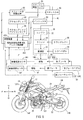
- FIG. 1 shows the left side view of the tilting vehicle according to the embodiment of the present invention, and the block diagram of the control system included in the tilting vehicle together. It is a top view of the tilting vehicle according to the embodiment of this invention. It is a block diagram of the control device provided in the inclined vehicle by embodiment of this invention. It is a flowchart which shows the drive wheel rotation speed increase assist control executed by the control device provided in the inclined vehicle by embodiment of this invention. It is a drawing which shows both the left side view of the tilting vehicle according to the first modification of the embodiment of the present invention, and the block diagram of the control system included in the tilting vehicle. FIG.
- FIG. 5 is a block diagram of a control device included in a tilting vehicle according to a first modification of the embodiment of the present invention. It is a flowchart which shows the drive wheel rotation speed increase assist control executed by the control device provided in the inclined vehicle by the modification 1 of the Embodiment of this invention. It is a drawing which shows both the left side view of the tilting vehicle according to the second modification of the embodiment of the present invention, and the block diagram of the control system included in the tilting vehicle.
- FIG. 5 is a block diagram of a control device included in a tilting vehicle according to a second modification of the embodiment of the present invention.
- FIG. 1 is a drawing showing a left side view of the tilting vehicle 10 and a block diagram of a control system included in the tilting vehicle 10.
- the front direction of the inclined vehicle 10 is defined as the vehicle front direction F.
- the rear direction of the inclined vehicle 10 is defined as the vehicle rear direction B.
- the left direction of the inclined vehicle 10 is defined as the vehicle left direction L.
- the right direction of the inclined vehicle 10 is defined as the vehicle right direction R.
- the upward direction of the inclined vehicle 10 is defined as the vehicle upward direction U.
- the downward direction of the inclined vehicle 10 is defined as the vehicle downward direction D.
- the front-rear direction of the inclined vehicle 10 is defined as the vehicle front-rear direction FB.
- the left-right direction of the inclined vehicle 10 is defined as the vehicle left-right direction LR.
- the vertical direction of the inclined vehicle 10 is defined as the vehicle vertical direction UD.
- the front-rear, up-down, left-right directions of the tilting vehicle 10 are the front-rear, up-down, left-right directions as seen from the occupant seated on the seat 24 of the inclined vehicle 10.
- the vehicle body 12 can be inclined to the left direction L of the vehicle or the right direction R of the vehicle.
- the vertical and horizontal directions of the vehicle body 12 do not match the vertical UD and the horizontal LR of the tilted vehicle 10.
- the vertical direction and the horizontal direction of the vehicle body 12 in the upright state coincide with the vertical direction UD and the horizontal direction LR of the inclined vehicle 10.
- the tilting vehicle 10 is a motorcycle as a saddle-mounted vehicle.
- the tilting vehicle 10 includes a vehicle body 12 as an inclined vehicle body, front wheels 14F, and rear wheels 14B.
- the vehicle body 12 rotatably supports the front wheels 14F and the rear wheels 14B, respectively.
- the vehicle body 12 tilts to the left L of the vehicle together with the front wheels 14 and the rear wheels 14B due to the force exerted by the occupants due to the left turning operation by the occupants.
- the force is applied from the occupant due to the right turning operation by the occupant, so that the vehicle tilts in the right direction R of the vehicle together with the front wheels 14F and the rear wheels 14B.
- the vehicle body 12 includes the vehicle body frame 121.
- the body frame 121 includes a head pipe 1211.
- the head pipe 1211 is provided at the front end portion of the vehicle body frame 121.
- the tilting vehicle 10 further includes a steering shaft 16, a steering wheel 18, and a front fork 20.
- the steering shaft 16 is inserted into the head pipe 1211.
- the handle 18 is provided at the upper end of the steering shaft 16.
- the front fork 20 is provided at the lower end of the steering shaft 16.
- the front fork 20 rotatably supports the front wheel 14F.
- the steering shaft 16 rotates when the steering wheel 18 is operated. As the steering shaft 16 rotates, the front fork 20 rotates. As a result, the front wheels 14F are steered. That is, the front wheels 14F are steering wheels.
- the tilting vehicle 10 further includes a rear arm 22.
- the rear arm 22 is provided so as to be swingable with respect to the vehicle body frame 121.
- the rear arm 22 rotatably supports the rear wheel 14B. In this state, the rear wheel 14B is located behind the front wheel 14F.
- the tilting vehicle 10 further includes a seat 24.
- the seat 24 is supported by the vehicle body frame 121. The occupant of the tilting vehicle 10 sits on the seat 24 while driving the tilting vehicle 10.
- the tilting vehicle 10 further includes a power unit 30.
- the power unit 30 is supported by the body frame 121.
- the rear wheel 14B rotates by transmitting the power from the power unit 30. That is, the rear wheel 14B is a driving wheel.
- the power unit 30 includes, for example, an engine 32 as a drive source, a transmission 34, and a clutch 36. These will be described below.
- the engine 32 has a combustion chamber for burning the air-fuel mixture.
- the air-fuel mixture in the combustion chamber is ignited by a spark discharge generated by a spark plug.
- the air-fuel mixture is a mixture of intake air and fuel.
- the engine 32 is, for example, a 4-stroke engine.
- a 4-stroke engine is an engine that repeats an intake stroke, a compression stroke, a combustion stroke (expansion stroke), and an exhaust stroke. In a 4-stroke engine, the intake stroke, compression stroke, combustion stroke (expansion stroke), and exhaust stroke are set as one cycle.
- the transmission 34 can change the torque and the number of revolutions of the engine 32 transmitted to the rear wheels 14B according to the traveling state.
- the transmission 34 is arranged on a path in which the power from the engine 32 is transmitted to the rear wheels 14B. That is, the transmission 34 is provided between the engine 32 and the rear wheels 14B.
- the transmission 34 can change the torque and the number of revolutions of the engine 32 transmitted to the rear wheels 14B by the occupant operating the shift pedal 68 described later to change the gear combination. That is, the transmission 34 is a so-called manual transmission.
- the clutch 36 switches between a power transmission allowable state and a power transmission cutoff state.
- the power from the engine 32 is transmitted to the rear wheels 14B.
- the power transmission cutoff state the power from the engine 32 is not transmitted to the rear wheels 14B.
- the clutch 36 is arranged on a path in which the power from the engine 32 is transmitted to the rear wheels 14B. That is, the clutch 36 is provided between the engine 32 and the rear wheel 14B. More specifically, the clutch 36 is provided between the engine 32 and the transmission 34.
- the clutch 36 switches between a power transmission allowable state and a power transmission cutoff state by the occupant operating the clutch lever 66 described later. When the occupant is not operating the clutch lever 66, the clutch 36 is maintained in the power transmission allowable state.
- the tilting vehicle 10 further includes a throttle valve 40.
- the throttle valve 40 is arranged in an intake passage 42 in which intake air, which is air sucked from the atmosphere, flows toward the combustion chamber of the engine 32.
- the throttle valve 40 is arranged in the intake passage 42 in a state of being rotatable around a predetermined rotation center axis so that the amount of intake air flowing toward the combustion chamber of the engine 32 can be adjusted.
- the predetermined rotation center axis extends in the direction orthogonal to the direction in which the intake air flows through the intake passage 42.
- the adjustment of the amount of intake air flowing toward the combustion chamber of the engine 32 by the throttle valve 40 is realized, for example, by changing the passage cross-sectional area of the intake passage 42 due to the rotation of the throttle valve 40 around the rotation center axis. Will be done.
- the throttle valve 40 is linked to the movement of the accelerator grip 64 as an accelerator operator, which will be described later. Specifically, when the accelerator grip 64 is rotated in the first direction, the throttle valve 40 moves so that the amount of intake air flowing through the intake passage 42 increases. By rotating the accelerator grip 64 in the second direction (opposite to the first direction), the throttle valve 40 moves so that the amount of intake air flowing through the intake passage 42 is reduced. That is, the throttle valve 40 adjusts the amount of intake air flowing through the intake passage 42 according to the movement of the accelerator grip 64. The opening degree of the throttle valve 40 is changed according to the amount of rotation of the accelerator grip 64 in the first direction.
- the tilting vehicle 10 further includes an injector 50.
- the injector 50 injects fuel toward the intake air flowing through the intake passage 42.
- the injector 50 adjusts the fuel injection amount according to the opening degree of the throttle valve 40 and the like.
- the injector 50 is arranged between the throttle valve 40 and the combustion chamber of the engine 32.
- the inclined vehicle 10 further includes a braking device 60, a brake operator 62, an accelerator grip 64 as an accelerator operator, a clutch lever 66 as a clutch operator, and a shift pedal 68 as a shift operator.
- the braking device 60 includes a front brake 60F and a rear brake 60B.
- the brake operator includes a front brake lever 62F and a rear brake pedal 62B.
- the front brake 60F reduces the rotational speed of the front wheels 14F. That is, the front brake 60F reduces the vehicle speed of the inclined vehicle 10.
- the front brake 60F converts kinetic energy based on the rotation of the front wheels 14F into thermal energy by friction.
- the front brake 60F is, for example, a disc brake.
- the front brake lever 62F is operated by the occupant when the front brake 60F reduces the rotational speed of the front wheels 14F.
- the arrangement of the front brake lever 62F will be described later.
- the rear brake 60B reduces the rotational speed of the rear wheels 14B. That is, the rear brake 60B reduces the vehicle speed of the inclined vehicle 10.
- the rear brake 60B converts kinetic energy based on the rotation of the rear wheels 14B into thermal energy by friction.
- the rear brake 60B is, for example, a disc brake.
- the rear brake pedal 62B is operated by the occupant when the rear brake 60B reduces the rotational speed of the rear wheels 14B.
- the arrangement of the rear brake pedal 62B will be described later.
- the accelerator grip 64 is used to increase the power from the engine 32.
- the power from the engine 32 is increased.
- the output of the engine 32 is increased by operating the accelerator grip 64 by the occupant.
- the rotational speed of the rear wheels 14B increases. The arrangement of the accelerator grip 64 will be described later.
- the clutch lever 66 is used to switch the clutch 36 to either a power transmission allowable state or a power transmission cutoff state.
- the clutch lever 66 is operated by the occupant when switching the clutch 36 to either the power transmission allowable state or the power transmission cutoff state.
- the clutch lever 66 does not need to be operated by an occupant when maintaining the clutch 36 in the power transmission allowable state. The arrangement of the clutch lever 66 will be described later.
- the shift pedal 68 is used to change the gear combination in the transmission 34.
- the shift pedal 68 is operated by the occupant when changing the gear combination in the transmission 34.
- the arrangement of the shift pedal 68 will be described later.
- FIG. 2 is a plan view of the tilting vehicle 10.
- the tilting vehicle 10 further includes a left step 70L and a right step 70R. These will be described below.
- the left foot of the occupant seated on the seat 24 is placed on the left step 70L. That is, the left step 70L is arranged at a position where the occupant seated on the seat 24 can put his / her left foot.
- the left step 70L is attached to the vehicle body frame 121.
- the left step 70L extends in the vehicle left-right direction LR.
- the right foot of the occupant seated on the seat 24 is placed on the right step 70R. That is, the right step 70R is arranged at a position where the occupant seated on the seat 24 can put his / her right foot.
- the right step 70R is attached to the vehicle body frame 121.
- the right step 70R extends in the vehicle left-right direction LR.
- the front brake lever 62F extends in the vehicle left-right direction LR.
- the front brake lever 62F is attached to the steering wheel 18 in a state where it can swing in the vehicle front-rear direction FB centering on the left end portion.
- the front brake lever 62F is located in front of the right portion of the handle 18 when viewed in the vehicle upward direction U or the vehicle downward direction D. That is, the front brake lever 62F is arranged near the right grip of the handle 18.
- the front brake lever 62F is arranged at a position where the occupant can operate it.
- the rear brake pedal 62B extends in the vehicle front-rear direction FB.
- the rear brake pedal 62B is attached to the vehicle body frame 121 in a state where it can swing in the vehicle vertical direction UD around the rear end portion.
- the front end of the rear brake pedal 62B is located in front of the right step 70R when viewed in the vehicle upward direction U or the vehicle downward direction D.
- the occupant can operate the rear brake pedal 62B while placing his right foot on the right step 70R. That is, the rear brake pedal 62B is arranged at a position where the occupant can operate it.
- the accelerator grip 64 extends in the vehicle left-right direction LR.
- the accelerator grip 64 is provided on the right side of the steering wheel 18.
- the accelerator grip 64 functions as a right grip of the steering wheel 18. The occupant can operate the accelerator grip 64 while driving the tilting vehicle 10. That is, the accelerator grip 64 is arranged at a position where the occupant can operate it.
- the clutch lever 66 extends in the vehicle left-right direction LR.
- the clutch lever 66 is attached to the steering wheel 18 in a state where it can swing in the vehicle front-rear direction FB with the right end portion as the center.
- the clutch lever 66 is located in front of the left portion of the handle 18 when viewed in the vehicle upward direction U or the vehicle downward direction D. That is, the clutch lever 66 is arranged near the left grip of the handle 18. As a result, the occupant can operate the clutch lever 66 while touching the left grip of the steering wheel 18. That is, the clutch lever 66 is arranged at a position where the occupant can operate it.
- the shift pedal 68 extends in the front-rear direction FB of the vehicle.
- the shift pedal 68 is attached to the vehicle body frame 121 in a state where it can swing in the vehicle vertical direction UD around the rear end portion.
- the front end of the shift pedal 68 is located in front of the left step 70L when viewed in the vehicle upward direction U or the vehicle downward direction D.
- the occupant can operate the shift pedal 68 while placing his / her left foot on the left step 70L. That is, the shift pedal 68 is arranged at a position where the occupant can operate it.
- the tilting vehicle 10 further includes a control device 80.
- the control device 80 increases the rotational speed of the rear wheels 14B by increasing the power transmitted from the engine 32 to the rear wheels 14B based on the operation of the occupant on the accelerator grip 64.
- the control device 80 is, for example, an ECU (Electronic Control Unit).
- the ECU is realized by, for example, a combination of an IC (Integrated Circuit), an electronic component, a circuit board, and the like.
- the control device 80 includes a drive wheel rotation speed increase assist control unit 82.
- the drive wheel rotation speed increase assist control unit 82 is realized, for example, by a CPU (Central Processing Unit) reading a program stored in a non-volatile memory and executing a predetermined process according to the program.
- a CPU Central Processing Unit
- the drive wheel rotation speed increase assist control unit 82 increases the output of the engine 32 even if the occupant does not perform the drive wheel rotation speed increase operation in order to increase the centrifugal force acting on the tilting vehicle 10 during turning.
- the drive wheel rotation speed increasing operation is an operation performed by the occupant on the accelerator grip 64 in order to increase the rotation speed of the rear wheels 14B.
- the operation of rotating the accelerator grip 64 in the first direction corresponds to the operation of increasing the rotation speed of the drive wheels.
- the vehicle speed when the inclined vehicle 10 can travel without the occupant performing the operation for increasing the rotation speed of the drive wheels is, for example, 5 to 20 km / h.
- the inclined vehicle 10 further includes an accelerator grip position sensor 90, a throttle valve drive device 92, a rear wheel speed sensor 94B as a drive wheel rotation speed sensor, and a throttle opening sensor 95. These will be described below.
- the accelerator grip position sensor 90 detects the rotation angle of the accelerator grip 64 from the initial position, that is, the amount of operation of the accelerator grip 64.
- the accelerator grip position sensor 90 inputs the detected operation amount of the accelerator grip 64 to the control device 80.
- the throttle valve drive device 92 drives the throttle valve 40 based on the signal from the control device 80.
- the throttle valve drive device 92 includes, for example, an electric motor and a speed reduction mechanism.
- the rear wheel speed sensor 94B detects the rotational speed of the rear wheel 14B.
- the rear wheel speed sensor 94B inputs the detected rotation speed of the rear wheel 14B to the control device 80.
- the throttle opening sensor 95 detects the throttle opening, which is the opening of the throttle valve 40.
- the throttle opening sensor 95 inputs the detected throttle opening to the control device 80.
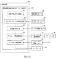
- FIG. 3 is a block diagram of the control device 80.
- the drive wheel rotation speed increase assist control unit 82 includes a tilting vehicle travel determination unit 821, an accelerator grip operation determination unit 822, a throttle opening adjustment unit 823, and an injector control unit 824.
- the inclined vehicle running determination unit 821, the accelerator grip operation determination unit 822, the throttle opening adjustment unit 823, and the injector control unit 824 read, for example, a program stored in the non-volatile memory by the CPU (Central Processing Unit), respectively. It is realized by executing a predetermined process according to the program.
- the tilting vehicle travel determination unit 821 determines whether or not the tilting vehicle 10 is traveling based on the rotation speed of the rear wheels 14B input from the rear wheel speed sensor 94B.
- the accelerator grip operation determination unit 822 determines whether or not the accelerator grip 64 is being operated based on the amount of operation of the accelerator grip 64 input from the accelerator grip position sensor 90.
- the throttle opening adjustment unit 823 drives the throttle valve 40 so that the throttle opening becomes a predetermined throttle opening when the inclined vehicle 10 is traveling and the accelerator grip 64 is not operated. .. Specifically, a signal is input to the throttle valve drive device 92, and the throttle valve drive device 92 drives the throttle valve 40 based on the input signal.
- the injector control unit 824 sets the fuel injection amount based on the throttle opening degree input from the throttle opening degree sensor 95. Further, the injector control unit 824 controls the injector 50 so that the fuel is injected at the set injection amount.
- the injector control unit 824 may set the fuel injection amount by referring to not only the signal input from the throttle opening sensor 95 but also the signal input from another sensor, for example.
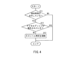
- FIG. 4 is a flowchart showing the drive wheel rotation speed increase assist control executed by the control device 80.
- step S11 the control device 80 determines whether or not the inclined vehicle 10 is traveling. The determination is made based on the rotational speed of the rear wheels 14B input from the rear wheel speed sensor 94B.
- step S11: NO When the tilting vehicle 10 is not traveling (step S11: NO), the control device 80 ends the drive wheel rotation speed increase assist control.
- step S11: YES the control device 80 determines in step S12 whether or not the accelerator grip 64 is being operated. The determination is made based on the amount of operation of the accelerator grip 64 input from the accelerator grip position sensor 90.
- step S12 When the accelerator grip 64 is operated (step S12: YES), the control device 80 ends the drive wheel rotation speed increase assist control.
- step S12: NO the control device 80 inputs a signal for adjusting the throttle opening degree to the throttle valve drive device 92 in step S13.
- the signal is a signal for changing the throttle valve 40 to a state different from the fully closed state even when the accelerator grip 64 is not operated.
- the signal is a signal for maintaining the throttle valve 40 from the fully closed position to a slightly open position when the accelerator grip 64 is not operated.
- the throttle valve drive device 92 adjusts the throttle opening degree based on the input signal. After that, the control device 80 ends the drive wheel rotation speed increase assist control.
- step S12 instead of determining "whether or not the accelerator grip 64 is operated (step S12)", for example, "whether or not the vehicle speed is equal to or higher than a predetermined vehicle speed" or "shift". Whether or not the position is in 1st gear ”may be determined. If the vehicle speed is equal to or higher than the predetermined vehicle speed, or if the shift position is other than the first speed, the process of step S13 is not executed.
- the fuel injection amount set by the injector control unit 824 also changes. Specifically, the fuel injection amount set by the injector control unit 824 is larger than that when the throttle valve 40 is in the fully closed position. As a result, the rotation speed of the engine 32 increases.
- the rotation speed of the engine 32 can be increased even if the accelerator grip 64 is not operated when the inclined vehicle 10 is traveling. Therefore, if the clutch 36 is engaged by not operating the clutch lever 66, the tilting vehicle 10 can be driven at a low speed (for example, 10 km / h or less). In this case, even if the tilting vehicle 10 is turned, the centrifugal force acting on the tilting vehicle 10 during turning can be secured. That is, it is not necessary to operate the accelerator grip 64 and the clutch lever 66 when turning the inclined vehicle 10. Therefore, it is possible to reduce the burden on the occupant when turning the inclined vehicle 10. As a result, the tilting vehicle 10 can be easily turned at a low speed.
- the vehicle speed of the tilting vehicle 10 can be reduced by operating the front brake lever 62F or the rear brake pedal 62B by the occupant. Therefore, when turning the tilting vehicle 10, the occupant can adjust the vehicle speed of the tilting vehicle 10 during turning. That is, the front brake lever 62F and the rear brake pedal 62B can reduce the vehicle speed of the inclined vehicle 10 even when the accelerator grip 64 and the clutch lever 66 are not operated, respectively.
- the vehicle speed of the tilting vehicle 10 can be reduced simply by operating the rear brake pedal 62B with the right foot of the occupant. Therefore, the occupant does not have to operate the front brake lever 62F in order to reduce the vehicle speed during turning of the inclined vehicle 10. As a result, it is possible to reduce the burden on the occupant when turning the inclined vehicle 10.
- FIG. 5 is a drawing showing a left side view of the tilting vehicle 10A and a block diagram of a control system included in the tilting vehicle 10A.
- the tilting vehicle 10A is different from the tilting vehicle 10 in that it further includes a front wheel speed sensor 94F as a steering wheel rotation speed sensor.
- the front wheel speed sensor 94F detects the rotational speed of the front wheel 14F.
- the front wheel speed sensor 94F inputs the detected rotation speed of the front wheel 14F to the control device 80A.
- the tilting vehicle 10A is different from the tilting vehicle 10 in that the control device 80A is provided instead of the control device 80.
- the control device 80A will be described with reference to FIG. FIG. 6 is a block diagram of the control device 80A.
- the control device 80A includes a drive wheel rotation speed increase assist control unit 82A instead of the drive wheel rotation speed increase assist control unit 82.
- the drive wheel rotation speed increase assist control unit 82A further includes a turning travel determination unit 825 as compared with the drive wheel rotation speed increase assist control unit 82.
- the turning traveling determination unit 825 is based on the difference in rotational speed, which is the difference between the rotational speed of the front wheels 14F detected by the front wheel speed sensor 94F and the rotational speed of the rear wheels 14B detected by the rear wheel speed sensor 94B. It is determined whether or not the vehicle is traveling while turning.
- the turning travel determination unit 825 determines a rotational speed difference, which is a difference between the rotational speed of the front wheels 14F detected by the front wheel speed sensor 94F and the rotational speed of the rear wheels 14B detected by the rear wheel speed sensor 94B. When it is larger than the rotation speed difference, it is determined that the inclined vehicle 10A is traveling while turning.
- the turning travel determination unit 825 is realized, for example, by the CPU (Central Processing Unit) reading a program stored in the non-volatile memory and executing a predetermined process according to the program.
- CPU Central Processing Unit
- FIG. 7 is a flowchart showing the drive wheel rotation speed increase assist control executed by the control device 80A.
- step S21 the control device 80A determines whether or not the tilting vehicle 10A is traveling. The determination is made based on the rotational speed of the rear wheels 14B input from the rear wheel speed sensor 94B.
- step S21: NO When the tilting vehicle 10A is not traveling (step S21: NO), the control device 80A ends the drive wheel rotation speed increase assist control.
- step S21: YES the control device 80A determines in step S22 whether or not the accelerator grip 64 is being operated. The determination is made based on the amount of operation of the accelerator grip 64 input from the accelerator grip position sensor 90.
- step S22: YES When the accelerator grip 64 is operated (step S22: YES), the control device 80A ends the drive wheel rotation speed increase assist control.
- step S22: NO the control device 80A determines in step S23 whether or not the tilting vehicle 10A is turning. The determination is made based on the difference in rotational speed, which is the difference between the rotational speed of the front wheels 14F detected by the front wheel speed sensor 94F and the rotational speed of the rear wheels 14B detected by the rear wheel speed sensor 94B.
- step S23: NO When the tilting vehicle 10A is not turning (step S23: NO), the control device 80A ends the drive wheel rotation speed increase assist control.
- step S23: YES the control device 80A inputs a signal for adjusting the throttle opening degree to the throttle valve drive device 92 in step S24.
- the throttle valve drive device 92 adjusts the throttle opening degree based on the input signal. After that, the control device 80A ends the drive wheel rotation speed increase assist control.
- step S22 instead of determining "whether or not the accelerator grip 64 is operated (step S22)", for example, "whether or not the vehicle speed is equal to or higher than a predetermined vehicle speed" or "shift". Whether or not the position is in 1st gear ”may be determined. If the vehicle speed is equal to or higher than the predetermined vehicle speed, or if the shift position is other than the first speed, the process of step S24 is not executed.
- the fuel injection amount set by the injector control unit 824 also changes. Specifically, the fuel injection amount set by the injector control unit 824 is larger than that when the throttle valve 40 is in the fully closed position. As a result, the rotation speed of the engine 32 increases.
- the control device 80A executes the drive wheel rotation speed increase assist control, it is determined whether or not the tilting vehicle 10A is turning. Therefore, the rotation speed of the engine 32 can be increased without operating the accelerator grip 64 only when the inclined vehicle 10A is actually turning.
- FIG. 8 is a drawing showing a left side view of the tilting vehicle 10B and a block diagram of a control system included in the tilting vehicle 10B.
- the tilting vehicle 10B is different from the tilting vehicle 10 in that it further includes a gear position detection sensor 96.
- the gear position detection sensor 96 detects the gear position in the transmission 34.
- the gear position detection sensor 96 inputs the detected gear position of the transmission 34 to the control device 80B.
- the tilting vehicle 10B is different from the tilting vehicle 10 in that the control device 80B is provided instead of the control device 80.
- the control device 80B will be described with reference to FIG.
- FIG. 9 is a block diagram of the control device 80B.
- the control device 80B is different from the control device 80 in that the drive wheel rotation speed increase assist control unit 82B is provided instead of the drive wheel rotation speed increase assist control unit 82.
- the drive wheel rotation speed increase assist control unit 82B is different from the drive wheel rotation speed increase assist control unit 82 in that it further includes a gear position determination unit 826.
- the gear position determination unit 826 determines whether or not the gear position in the transmission 34 is the first gear based on the gear position in the transmission 34 detected by the gear position sensor 96.
- the gear position determination unit 826 is realized, for example, by the CPU (Central Processing Unit) reading a program stored in the non-volatile memory and executing a predetermined process according to the program.
- CPU Central Processing Unit
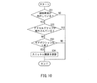
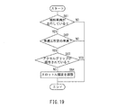
- FIG. 10 is a flowchart showing the drive wheel rotation speed increase assist control executed by the control device 80B.
- step S31 the control device 80B determines whether or not the tilting vehicle 10B is traveling. The determination is made based on the rotational speed of the rear wheels 14B input from the rear wheel speed sensor 94B.
- step S31: NO When the tilting vehicle 10B is not traveling (step S31: NO), the control device 80B ends the drive wheel rotation speed increase assist control.
- step S31: YES the control device 80B determines in step S32 whether or not the accelerator grip 64 is being operated. The determination is made based on the amount of operation of the accelerator grip 64 input from the accelerator grip position sensor 90.
- step S32: YES When the accelerator grip 64 is operated (step S32: YES), the control device 80B ends the drive wheel rotation speed increase assist control.
- step S32: NO the control device 80B determines in step S33 whether or not the gear position in the transmission 34 is the first gear. The determination is made based on the gear position in the transmission 34 detected by the gear position detection sensor 96.
- step S33: NO When the gear position in the transmission 34 is not the first gear (step S33: NO), the control device 80B ends the drive wheel rotation speed increase assist control.
- step S33: YES When the gear position in the transmission 34 is the first gear (step S33: YES), the control device 80B inputs a signal for adjusting the throttle opening to the throttle valve drive device 92 in step S34.
- the throttle valve drive device 92 adjusts the throttle opening degree based on the input signal. After that, the control device 80B ends the drive wheel rotation speed increase assist control.
- step S32 instead of determining "whether or not the accelerator grip 64 is being operated (step S32)", for example, "whether or not the vehicle speed is equal to or higher than a predetermined vehicle speed" is determined. May be good. If the vehicle speed is equal to or higher than the predetermined vehicle speed, the process of step S34 is not executed.
- the fuel injection amount set by the injector control unit 824 also changes. Specifically, the fuel injection amount set by the injector control unit 824 is larger than that when the throttle valve 40 is in the fully closed position. As a result, the rotation speed of the engine 32 increases.
- the control device 80B executes the drive wheel rotation speed increase assist control, it is determined whether or not the gear position in the transmission 34 is the first speed. Therefore, the rotation speed of the engine 32 can be increased without operating the accelerator grip 64 only when the gear position in the transmission 34 is the first gear.
- FIG. 11 is a drawing showing a left side view of the tilting vehicle 10C and a block diagram of a control system included in the tilting vehicle 10C.
- the tilting vehicle 10C is different from the tilting vehicle 10 in that it further includes a roll angle detection sensor 98.
- the roll angle detection sensor 98 detects the roll angle of the vehicle body 12.
- the roll angle detection sensor 98 inputs the detected roll angle of the vehicle body 12 to the control device 80C.
- the tilting vehicle 10C is different from the tilting vehicle 10 in that the control device 80C is provided instead of the control device 80.
- the control device 80C will be described with reference to FIG. FIG. 12 is a block diagram of the control device 80C.
- the control device 80C is different from the control device 80 in that the drive wheel rotation speed increase assist control unit 82C is provided instead of the drive wheel rotation speed increase assist control unit 82.
- the drive wheel rotation speed increase assist control unit 82C is different from the drive wheel rotation speed increase assist control unit 82 in that it further includes a turning travel determination unit 827.
- the turning travel determination unit 827 determines whether or not the tilting vehicle 10C is turning according to the roll angle of the vehicle body 12 detected by the roll angle detection sensor 98. Specifically, the turning travel determination unit 827 determines that the tilting vehicle 10C is turning when the roll angle of the vehicle body 12 detected by the roll angle detection sensor 98 is larger than a predetermined roll angle.
- the turning travel determination unit 827 is realized, for example, by the CPU (Central Processing Unit) reading a program stored in the non-volatile memory and executing a predetermined process according to the program.
- CPU Central Processing Unit
- FIG. 13 is a flowchart showing the drive wheel rotation speed increase assist control executed by the control device 80C.
- step S41 the control device 80C determines whether or not the inclined vehicle 10C is traveling. The determination is made based on the rotational speed of the rear wheels 14B input from the rear wheel speed sensor 94B.
- step S41: NO When the tilting vehicle 10C is not traveling (step S41: NO), the control device 80C ends the drive wheel rotation speed increase assist control.
- step S41: YES the control device 80C determines in step S42 whether or not the accelerator grip 64 is being operated. The determination is made based on the amount of operation of the accelerator grip 64 input from the accelerator grip position sensor 90.
- step S42 YES
- step S42: NO the control device 80C is turning the tilting vehicle 10C based on the roll angle of the vehicle body 12 detected by the roll angle detection sensor 98 in step S43. Judge whether or not.
- step S43: NO When the tilting vehicle 10C is not turning (step S43: NO), the control device 80C ends the drive wheel rotation speed increase assist control.
- step S43: YES the control device 80C inputs a signal for adjusting the throttle opening degree to the throttle valve drive device 92 in step S44.
- the throttle valve drive device 92 adjusts the throttle opening degree based on the input signal. After that, the control device 80C ends the drive wheel rotation speed increase assist control.
- step S42 instead of determining "whether or not the accelerator grip 64 is operated (step S42)", for example, "whether or not the vehicle speed is equal to or higher than a predetermined vehicle speed" or "shift". Whether or not the position is in 1st gear ”may be determined. If the vehicle speed is equal to or higher than the predetermined vehicle speed, or if the shift position is other than the first speed, the process of step S44 is not executed.
- the fuel injection amount set by the injector control unit 824 also changes. Specifically, the fuel injection amount set by the injector control unit 824 is larger than that when the throttle valve 40 is in the fully closed position. As a result, the rotation speed of the engine 32 increases.
- the tilting vehicle 10C when the control device 80C executes the drive wheel rotation speed increase assist control, the tilting vehicle 10C is turning based on the roll angle of the vehicle body 12 detected by the roll angle detection sensor 98. Whether or not it is judged. Therefore, the rotation speed of the engine 32 can be increased without operating the accelerator grip 64 only when the inclined vehicle 10C is turning.
- a roll rate detection sensor that detects the roll rate of the vehicle body 12 may be provided.
- the roll rate detection sensor inputs the detected roll rate of the vehicle body 12 to the control device 80C.
- the turning travel determination unit 827 included in the control device 80C determines whether or not the tilting vehicle 10C is turning based on the roll rate of the vehicle body 12 detected by the roll rate detection sensor.
- FIG. 14 is a drawing showing a left side view of the tilting vehicle 10D and a block diagram of a control system included in the tilting vehicle 10D.
- the tilting vehicle 10D is different from the tilting vehicle 10 in that it further includes a mode changeover switch 100.
- the mode changeover switch 100 switches between an assist mode in which the control device 80D executes the drive wheel rotation speed increase assist control and a normal mode in which the control device 80D does not execute the drive wheel rotation speed increase assist control.
- the mode changeover switch 100 is provided at a position where the occupant can operate it.
- the mode changeover switch 100 is provided on the handle 18, for example.
- the mode changeover switch 100 inputs a signal indicating the operation content by the occupant to the control device 80D.
- the tilting vehicle 10D is different from the tilting vehicle 10 in that it includes a control device 80D instead of the control device 80.
- the control device 80D will be described with reference to FIG.
- FIG. 15 is a block diagram of the control device 80D.
- the control device 80D is different from the control device 80 in that the drive wheel rotation speed increase assist control unit 82D is provided instead of the drive wheel rotation speed increase assist control unit 82.
- the drive wheel rotation speed increase assist control unit 82D is different from the drive wheel rotation speed increase assist control unit 82 in that it further includes a mode determination unit 828.
- the mode determination unit 828 determines whether or not the mode is in the assist mode based on the signal input from the mode changeover switch 100.
- the mode determination unit 828 is realized, for example, by the CPU (Central Processing Unit) reading a program stored in the non-volatile memory and executing a predetermined process according to the program.
- FIG. 16 is a flowchart showing the drive wheel rotation speed increase assist control executed by the control device 80D.
- step S51 the control device 80D determines whether or not it is in the assist mode based on the signal from the mode changeover switch 100. When not in the assist mode (step S51: NO), the control device 80D ends the drive wheel rotation speed increase assist control. In the assist mode (step S51: YES), the control device 80D determines in step S52 whether or not the tilting vehicle 10D is traveling. The determination is made based on the rotational speed of the rear wheels 14B input from the rear wheel speed sensor 94B.
- step S52: NO When the tilting vehicle 10D is not traveling (step S52: NO), the control device 80D ends the drive wheel rotation speed increase assist control.
- step S52: YES the control device 80D determines in step S53 whether or not the accelerator grip 64 is being operated. The determination is made based on the amount of operation of the accelerator grip 64 input from the accelerator grip position sensor 90.
- step S53: YES When the accelerator grip 64 is operated (step S53: YES), the control device 80D ends the drive wheel rotation speed increase assist control.
- step S53: NO the control device 80D inputs a signal for adjusting the throttle opening degree to the throttle valve drive device 92 in step S54.
- the throttle valve drive device 92 adjusts the throttle opening degree based on the input signal. After that, the control device 80D ends the drive wheel rotation speed increase assist control.
- step S53 instead of determining "whether or not the accelerator grip 64 is operated (step S53)", for example, "whether or not the vehicle speed is equal to or higher than a predetermined vehicle speed" or "shift". Whether or not the position is in 1st gear ”may be determined. If the vehicle speed is equal to or higher than the predetermined vehicle speed, or if the shift position is other than the first speed, the process of step S54 is not executed.
- the fuel injection amount set by the injector control unit 824 also changes. Specifically, the fuel injection amount set by the injector control unit 824 is larger than that when the throttle valve 40 is in the fully closed position. As a result, the rotation speed of the engine 32 increases.
- the control device 80D executes the drive wheel rotation speed increase assist control, it is determined whether or not the signal from the mode changeover switch 100 is a signal indicating the assist mode. .. Therefore, only in the assist mode, the rotation speed of the engine 32 can be increased without operating the accelerator grip 64.
- FIG. 17 is a drawing showing a left side view of the tilting vehicle 10E and a block diagram of a control system included in the tilting vehicle 10E.
- the tilting vehicle 10E is different from the tilting vehicle 10 in that the control device 80E is provided instead of the control device 80.
- FIG. 18 is a block diagram of the control device 80E.
- the control device 80E is different from the control device 80 in that the drive wheel rotation speed increase assist control unit 82E is provided instead of the drive wheel rotation speed increase assist control unit 82.
- the drive wheel rotation speed increase assist control unit 82E is different from the drive wheel rotation speed increase assist control unit 82 in that the vehicle speed determination unit 829 is further provided.
- the vehicle speed determination unit 829 determines whether or not the vehicle speed of the inclined vehicle 10E is equal to or lower than a predetermined vehicle speed based on the signal input from the rear wheel speed sensor 94B.
- the predetermined vehicle speed is, for example, 20 km / h.
- the vehicle speed determination unit 829 is realized, for example, by the CPU (Central Processing Unit) reading a program stored in the non-volatile memory and executing a predetermined process according to the program.
- CPU Central Processing Unit
- FIG. 19 is a flowchart showing the drive wheel rotation speed increase assist control executed by the control device 80E.
- step S61 the control device 80E determines whether or not the tilting vehicle 10E is traveling. The determination is made based on the rotational speed of the rear wheels 14B input from the rear wheel speed sensor 94B.
- step S61: NO When the tilting vehicle 10E is not traveling (step S61: NO), the control device 80E ends the drive wheel rotation speed increase assist control.
- step S61: YES the control device 80E determines in step S62 whether or not the vehicle speed of the tilting vehicle 10E is equal to or less than a predetermined vehicle speed.
- step S62: NO When the vehicle speed of the inclined vehicle 10E is higher than the predetermined vehicle speed (step S62: NO), the control device 80E ends the drive wheel rotation speed increase assist control.
- step S62: YES When the vehicle speed of the inclined vehicle 10E is equal to or lower than the predetermined vehicle speed (step S62: YES), the control device 80E determines whether or not the accelerator grip 64 is operated in step S63. The determination is made based on the amount of operation of the accelerator grip 64 input from the accelerator grip position sensor 90.
- step S63: YES When the accelerator grip 64 is operated (step S63: YES), the control device 80E ends the drive wheel rotation speed increase assist control.
- step S63: NO the control device 80E inputs a signal for adjusting the throttle opening degree to the throttle valve drive device 92 in step S64.
- the throttle valve drive device 92 adjusts the throttle opening degree based on the input signal. After that, the control device 80E ends the drive wheel rotation speed increase assist control.
- step S63 instead of determining "whether or not the accelerator grip 64 is operated (step S63)", for example, "whether or not the shift position is in the first speed" may be determined. Good. If the shift position is other than the 1st speed, the process of step S64 is not executed.
- the fuel injection amount set by the injector control unit 824 also changes. Specifically, the fuel injection amount set by the injector control unit 824 is larger than that when the throttle valve 40 is in the fully closed position. As a result, the rotation speed of the engine 32 increases.
- the control device 80E executes the drive wheel rotation speed increase assist control, it is determined whether or not the vehicle speed of the tilting vehicle 10E is equal to or less than a predetermined vehicle speed. Therefore, the rotation speed of the engine 32 can be increased without operating the accelerator grip 64 only when the vehicle speed of the inclined vehicle 10E is equal to or lower than a predetermined vehicle speed.
- the tilting vehicle 10 includes a clutch lever 66 and a shift pedal 68. Then, when the occupant operates the clutch operating lever 66 and the shift pedal 68, the gear combination in the transmission 34 is changed.
- the tilting vehicle to which the present invention is applied is not limited to the tilting vehicle provided with the clutch lever 66 and the shift pedal 68 as described above.
- the tilting vehicle according to the modified example 7 of the embodiment of the present invention is different from the tilting vehicle 10 in that it does not have the clutch lever 66 and the shift pedal 68. Further, the tilting vehicle according to the modified example 7 of the embodiment of the present invention is different in that it is provided with a centrifugal continuously variable transmission instead of the transmission 34 which is a so-called manual transmission. Further, the tilting vehicle according to the modified example 7 of the embodiment of the present invention is different in that it includes a centrifugal clutch instead of the clutch 36. Further, the tilting vehicle according to the modified example 7 of the embodiment of the present invention is different in that the rear brake lever is provided instead of the rear brake pedal 62B.
- the rotation speed of the engine 32 increases even if the accelerator grip 64 is not operated when the inclined vehicle is traveling. Therefore, the centrifugal clutch is engaged. As a result, the inclined vehicle can be driven at a low speed without operating the accelerator grip 64. Further, the vehicle speed of the inclined vehicle can be reduced by the occupant operating the front brake lever 62F or the rear brake lever. Therefore, the occupant can adjust the vehicle speed of the inclined vehicle in a state where the inclined vehicle can be driven at a low speed without operating the accelerator grip 64.
- the rotation speed of the engine 32 may increase only when the tilting vehicle is turning even if the accelerator grip 64 is not operated. .. Whether or not the inclined vehicle is turning may be determined based on, for example, the difference between the rotation speed of the front wheels 14F and the rotation speed of the rear wheels 14B.
- the inclined vehicle it may be determined whether or not the inclined vehicle is turning based on the roll angle or the roll rate of the vehicle body.
- the reason why the rotation speed of the engine 32 increases even if the accelerator grip 64 is not operated is that the control device executes the drive wheel rotation speed increase assist control. It may be limited to the mode. Switching of the assist mode can be realized by, for example, ON / OFF of the mode changeover switch.
- FIG. 20 is a drawing showing a left side view of the tilting vehicle 10F and a block diagram of a control system included in the tilting vehicle 10F.
- the tilting vehicle 10F is different from the tilting vehicle 10 in that it further includes an in-wheel motor 15 as a sub drive source. That is, the inclined vehicle 10F is an inn that generates power transmitted to the front wheels 14F as sub drive wheels in addition to the engine 30 as a main drive source that generates power transmitted to the rear wheels 14 as main drive wheels. A wheel motor 15 is provided. The in-wheel motor 15 is provided on the front wheel 14F.
- the tilting vehicle 10F is different from the tilting vehicle 10 in that the control device 80F is provided instead of the control device 80.
- FIG. 21 is a block diagram of the control device 80F.
- the control device 80F includes a sub drive wheel rotation speed increase assist control unit 84 and an injector control unit 86.
- the sub-drive wheel rotation speed increase assist control unit 84 and the injector control unit 86 for example, read a program stored in a non-volatile memory by a CPU (Central Processing Unit) and execute a predetermined process according to the program. It is realized by such as.
- CPU Central Processing Unit
- the sub drive wheel rotation speed increase assist control unit 84 applies power from the in-wheel motor 15 even if the occupant does not perform the drive wheel rotation speed increase operation.
- the vehicle speed of the inclined vehicle 10F is increased by transmitting the transmission to the front wheels 14F to increase the rotation speed of the front wheels 14F.
- the sub-drive wheel rotation speed increase assist control unit 84 includes an inclined vehicle travel determination unit 841, an accelerator grip operation determination unit 842, and an in-wheel motor control unit 843.
- the inclined vehicle running determination unit 841, the accelerator grip operation determination unit 842, and the in-wheel motor control unit 843 for example, each read a program stored in a non-volatile memory by a CPU (Central Processing Unit) and determine a predetermined program according to the program. It is realized by executing the process.
- a CPU Central Processing Unit
- the tilting vehicle travel determination unit 841 determines whether or not the tilting vehicle 10F is traveling based on the rotation speed of the rear wheels 14B input from the rear wheel speed sensor 94B.
- the accelerator grip operation determination unit 842 determines whether or not the accelerator grip 64 is being operated based on the amount of operation of the accelerator grip 64 input from the accelerator grip position sensor 90.
- the in-wheel motor control unit 843 drives the in-wheel motor 15 when the inclined vehicle 10F is running and the accelerator grip 64 is not operated. As a result, the power of the in-wheel motor 15 is transmitted to the front wheels 14F.
- the injector control unit 86 sets the fuel injection amount based on the throttle opening degree input from the throttle opening degree sensor 95. Further, the injector control unit 86 controls the injector 50 so that the fuel is injected at the set injection amount.
- the injector control unit 86 may set the fuel injection amount by referring to not only the signal input from the throttle opening sensor 95 but also the signal input from another sensor, for example.
- FIG. 22 is a flowchart showing the sub drive wheel rotation speed increase assist control executed by the control device 80F.
- step S71 the control device 80F determines whether or not the tilting vehicle 10F is traveling. The determination is made based on the rotational speed of the rear wheels 14B input from the rear wheel speed sensor 94B.
- step S71: NO When the inclined vehicle 10F is not traveling (step S71: NO), the control device 80F ends the sub drive wheel rotation speed increase assist control.
- step S71: YES the control device 80F determines in step S72 whether or not the accelerator grip 64 is being operated. The determination is made based on the amount of operation of the accelerator grip 64 input from the accelerator grip position sensor 90.
- step S72 YES
- step S72: NO the control device 80F drives the in-wheel motor 15 in step S73. After that, the control device 80F ends the sub-drive wheel rotation speed increase assist control.
- step S72 instead of determining "whether or not the accelerator grip 64 is operated (step S72)", for example, "whether or not the vehicle speed is equal to or higher than a predetermined vehicle speed" or "shift". Whether or not the position is in 1st gear ”may be determined. If the vehicle speed is equal to or higher than the predetermined vehicle speed, or if the shift position is other than the first speed, the process of step S73 is not executed.
- the in-wheel motor 15 When the in-wheel motor 15 is driven as described above, the power of the in-wheel motor 15 is transmitted to the front wheels 14F. As a result, the rotation speed of the front wheels 14F can be increased so that the inclined vehicle 10F can be driven at a low speed even if the accelerator grip 64 is not operated.
- the inclined vehicle 10F when the inclined vehicle 10F is traveling, the inclined vehicle 10F can be traveled at a low speed (for example, 10 km / h or less) even if the accelerator grip 64 is not operated. .. In this case, even if the tilting vehicle 10F is turned, the centrifugal force acting on the tilting vehicle 10F during turning can be secured. That is, it is not necessary to operate the accelerator grip 64 when turning the inclined vehicle 10F. Therefore, it is possible to reduce the burden on the occupant when turning the inclined vehicle 10F. As a result, it is possible to facilitate the turning running of the inclined vehicle 10F at a low speed.
- a low speed for example, 10 km / h or less
- the vehicle speed of the tilting vehicle 10F can be reduced by operating the front brake lever 62F or the rear brake pedal 62B by the occupant. Therefore, when turning the tilting vehicle 10F, the occupant can adjust the vehicle speed of the tilting vehicle 10F during turning.
- FIG. 23 is a graph showing the relationship between the vehicle speed and the roll response time of the inclined vehicle according to the embodiment of the present invention.
- FIG. 24 is a graph showing the relationship between the vehicle speed of the tilting vehicle and the maximum value of the roll rate according to the embodiment of the present invention.
- FIG. 23 shows the time from when the vehicle body is upright until the roll angle reaches a roll angle of a size corresponding to the input steering torque when a constant steering torque is input, that is, constant after the roll angle starts to change. The time required to reach the size of (roll response time) is recorded for each vehicle speed.
- FIG. 24 shows the maximum value of the roll rate when a constant steering torque is input from the upright state of the vehicle body for each vehicle speed.
- the lower the vehicle speed the larger the maximum value of the roll rate exponentially. Therefore, the maximum value of the roll rate can be reduced by increasing the vehicle speed a little. In other words, even with the same turning motion, the vehicle body slowly collapses just by increasing the vehicle speed a little. Therefore, the turning operation becomes easy.
- Such gist is an equal element, modification, deletion, combination (eg, combination of features across embodiments and variants), improvement, modification that can be recognized by those skilled in the art based on the embodiments disclosed herein. Including.
- the limitations of the claims should be broadly construed based on the terms used in the claims and are limited to the embodiments and variations described herein or in the process of the present application. Should not be done.
- Such embodiments and variations should be construed as non-exclusive.
- the terms "preferably” and “good” are non-exclusive and are “preferable but not limited to” and “good but not limited thereto”. It means "no".
- the tilting vehicle having an engine as a drive source has been described, but the present invention is also applied to a tilting vehicle having an electric motor as a drive source and a tilting vehicle having an engine and an electric motor as a drive source. It is, of course, possible to do so.
- the tilting vehicle 10 may include a front wheel speed sensor that detects the rotational speed of the front wheels 14F.
- the drive wheel rotation speed increase assist control unit 82 may determine whether or not the inclined vehicle 10 is traveling by using the rotation speed of the front wheels 14F detected by the front wheel speed sensor.
- the throttle opening does not have to be changed when the rotation speed of the engine 32 is increased.
- the throttle valve 40 may be a mechanical type that is driven by a throttle wire.
- Tilting train 12 Tilting train (tilting train) 14F front wheel (steering wheel) 14B rear wheel (drive wheel) 16 Steering shaft 18 Handle 20 Front fork 22 Rear arm 24 Seat 30 Power unit 32 Engine 34 Transmission 36 Clutch 40 Throttle valve 50 Injector 60 Braking device 60F Front brake 60B Rear brake 62 Brake operator 62F Front brake lever 62B Rear brake pedal 64 Accelerator grip 66 Clutch lever 68 Shift pedal 70L Left step 70R Right step 80 Control device 82 Drive wheel rotation speed increase Assist control unit 821 Inclined vehicle travel judgment unit 822 Accelerator grip operation judgment unit 823 Throttle opening adjustment unit 824 Injector control unit 825 Turning travel judgment Part 826 Gear position judgment part 827 Turning running judgment part 828 Mode judgment part 829 Vehicle speed judgment part 90 Accelerator grip position sensor 92 Throttle valve drive device 94F Front wheel speed sensor 94B Rear wheel speed sensor 95 Throttle opening sensor 96 Gear position detection sensor 98 Roll Angle
Landscapes
- Engineering & Computer Science (AREA)
- Mechanical Engineering (AREA)
- Chemical & Material Sciences (AREA)
- Combustion & Propulsion (AREA)
- Transportation (AREA)
- General Engineering & Computer Science (AREA)
- Automation & Control Theory (AREA)
- Electric Propulsion And Braking For Vehicles (AREA)
- Automatic Cycles, And Cycles In General (AREA)
- Vehicle Body Suspensions (AREA)
Abstract
低速走行時の旋回を容易にすることができる傾斜車両を提供する。傾斜車両は、傾斜車両が旋回しながら走行しているときに傾斜車両に作用する遠心力を増加させるために、駆動源からの動力が伝達されることで回転する駆動輪の回転速度を増加させるために乗員がアクセル操作子に対して行う操作である駆動輪回転速度増加操作を乗員が行わなくても、駆動源から駆動輪に伝達される動力を増加させて駆動輪の回転速度を増加させることで傾斜車両の車速を増加させる駆動輪回転速度増加アシスト制御部を含む制御装置と、駆動輪回転速度増加アシスト制御部が駆動源からの動力を増加させて駆動輪の回転速度を増加させることで増加している傾斜車両の車速を減少させるために用いられ、乗員による操作が可能な制動装置とを備える。
Description
本発明は、左旋回時には左方向に傾斜し、右旋回時には右方向に傾斜する傾斜車体を備える傾斜車両に関する。
従来、自動二輪車等の傾斜車両が知られている。傾斜車両は、傾斜車体を備える。傾斜車体は、左旋回時には乗員による左旋回動作に起因して乗員から力が及ぼされることで左方向に傾斜し、右旋回時には乗員による右旋回動作に起因して乗員から力が及ぼされることで右方向に傾斜する。そのため、傾斜車両を運転する際には、傾斜車体の傾斜角を考慮する必要がある。
傾斜車両としての二輪車に関し、特に低速域での走行安定性を確保するための技術、より具体的には、低速旋回時の走行安定性を確保して、低速走行時の旋回を容易にするための技術が知られている。このような技術は、例えば、国際公開第2014/017138号に開示されている。
上記公報では、車体の傾斜角に関して、車体速度に応じた最大許容傾斜角が予め設定されている。実際の車体の傾斜角が上記最大許容傾斜角を超えた場合に、車体速度を増加させる。
また、上記公報では、より好ましい態様として、所定時間後の車体の走行状態を推定して車体速度を制御することが開示されている。具体的には、車体の所定時間後の傾斜角である推定傾斜角が、車体の実際の傾斜角の時間変化に基づいて推定される。車体の所定時間後の車体速度である推定車体速度が、車体の実際の車体速度の時間変化に基づいて推定される。推定傾斜角が推定車体速度に対応する最大許容傾斜角を超える場合、或いは、超えそうな場合には、車体速度を増加させるように、或いは、車体速度の減少を抑制するように、車体速度を制御する。
このように、低速走行時の旋回を容易にすることができる傾斜車両が求められている。
本発明の目的は、従来とは異なる技術思想で、低速走行時の旋回を容易にすることができる傾斜車両を提供することである。
上記の目的を達成するために、本発明者は、傾斜車両について検討した。その結果、以下の知見を得るに至った。
傾斜車両は、傾斜車体を備える。傾斜車体は、左旋回時には乗員による左旋回動作に起因して乗員から力が及ぼされることで左方向に傾斜し、右旋回時には乗員による右旋回動作に起因して乗員から力が及ぼされることで右方向に傾斜する。このようにして傾斜車体が旋回中に傾斜することにより、旋回中の傾斜車両に作用する向心力と遠心力が釣り合う。
旋回中の傾斜車両に作用する遠心力の大きさは、車速の大きさに応じて変化する。つまり、車速が大きい場合には、旋回中の傾斜車両に作用する遠心力が大きくなる。一方、車速が小さい場合には、旋回中の傾斜車両に作用する遠心力が小さくなる。
このような知見に基づいて、本発明者は、さらなる検討を行った。その結果、以下の知見を得るに至った。
低速で旋回するときに車速を増加させれば、旋回中の傾斜車両に作用する遠心力を大きくすることができる。車速の増加は、乗員によるアクセル操作子の操作に起因するものである。しかしながら、アクセル操作子を操作しながら傾斜車体を傾けるのは、特に乗員が初心者である場合に、傾斜車両を旋回走行させる際の乗員への負担が大きくなる。そこで、低速で旋回するときには、乗員がアクセル操作子を操作しなくても、車速を増加させるようにすれば、旋回中の傾斜車両に作用する遠心力を確保することができる。そのため、乗員が傾斜車両を旋回走行させる際の負担を軽減することができる。その結果、低速での旋回が容易になる。本発明は、このような知見に基づいて完成されたものである。
本発明の一実施形態に係る傾斜車両は、駆動源と、駆動輪と、傾斜車体と、アクセル操作子とを備える。駆動輪は、駆動源からの動力が伝達されることで回転する。傾斜車体は、駆動源及び駆動輪を支持する。傾斜車体は、左旋回時には乗員による左旋回動作に起因して乗員から力が及ぼされることで駆動輪とともに左方向に傾斜し、右旋回時には乗員による右旋回動作に起因して乗員から力が及ぼされることで駆動輪とともに右方向に傾斜する。アクセル操作子は、駆動源から駆動輪に伝達される動力を増加させて、駆動源からの動力が伝達されることで回転する駆動輪の回転速度を増加させるために用いられる。アクセル操作子は、乗員による操作が可能である。
本発明の一実施形態に係る傾斜車両は、制御装置と、制動装置とをさらに備える。制御装置は、乗員のアクセル操作子への操作に基づいて駆動源から駆動輪に伝達される動力を増加させることで駆動輪の回転速度を増加させる。制御装置は、駆動輪回転速度増加アシスト制御部を含む。駆動輪回転速度増加アシスト制御部は、傾斜車両が旋回しながら走行しているときに傾斜車両に作用する遠心力を増加させるために、乗員が駆動輪回転速度増加操作を行わなくても駆動源から駆動輪に伝達される動力を増加させて駆動輪の回転速度を増加させることで傾斜車両の車速を増加させる。駆動輪回転速度増加操作は、駆動源からの動力が伝達されることで回転する駆動輪の回転速度を増加させるために乗員がアクセル操作子に対して行う操作である。制動装置は、駆動輪回転速度増加アシスト制御部が駆動源からの動力を増加させて駆動輪の回転速度を増加させることで増加している傾斜車両の車速を減少させるために用いられる。制動装置は、乗員による操作が可能である。
本発明の一実施形態に係る傾斜車両においては、乗員がアクセル操作子を操作しなくても、傾斜車両の車速を増加させることができる。そのため、傾斜車両が旋回しているときの乗員の操作負担を軽減しつつ、旋回中の傾斜車両に作用する遠心力を確保することができる。その結果、低速での傾斜車両の旋回走行を容易にすることができる。
なお、乗員がアクセル操作子を操作せずに増加した傾斜車両の車速は、乗員が制動装置を操作することで適宜減少させることができる。そのため、傾斜車両の車速は、乗員の意思により、適宜調整することができる。
本発明の一実施形態に係る傾斜車両は、例えば、少なくとも1つの前輪と、少なくとも1つの後輪とを備える。つまり、傾斜車両は、二輪車に限定されず、前輪又は後輪が左右一対の車輪で構成された三輪車であってもよいし、前輪及び後輪がそれぞれ左右一対の車輪で構成された四輪車であってもよい。
本発明の一実施形態に係る傾斜車両において、駆動源は、駆動輪に伝達される動力を発生させるものであれば、特に限定されない。駆動源は、例えば、エンジンであってもよいし、電気モータであってもよいし、エンジンと電気モータの両方を備えるものであってもよい。駆動源がエンジンである場合、傾斜車両は、例えば、過給機を備えていてもよい。過給機は、例えば、ターボチャージャーであってもよいし、スーパーチャージャーであってもよい。
本発明の一実施形態に係る傾斜車両において、駆動輪は、駆動源からの動力が伝達されることで回転するものであれば、特に限定されない。傾斜車両が前輪及び後輪を備える場合、駆動輪は、前輪であってもよいし、後輪であってもよい。
本発明の一実施形態に係る傾斜車両において、傾斜車体は、駆動源及び駆動輪を支持し、左旋回時には乗員による左旋回動作に起因して乗員から力が及ぼされることで駆動輪とともに左方向に傾斜し、右旋回時には乗員による右旋回動作に起因して乗員から力が及ぼされることで駆動輪とともに右方向に傾斜するものであれば、特に限定されない。傾斜車体は、車体フレームを含む。車体フレームは、複数の部品を組み合わせたフレ-ムであってもよいし、複数の部品を一体的に成形したフレ-ムであってもよい。車体フレームの材料は、アルミ、鉄などの金属であってもよいし、CFRPなどの合成樹脂であってもよいし、それらの組み合わせであってもよい。車体フレームは、傾斜車両の外観部品で構成したモノコック構造であってもよいし、その一部が傾斜車両の外観部品を兼ねるセミモノコック構造であってもよい。傾斜車体が駆動源を支持する態様は、特に限定されない。傾斜車体は、例えば、駆動源を直接支持していてもよいし、駆動源を間接的に支持していてもよい。傾斜車体が駆動輪を支持する態様は、特に限定されない。傾斜車体は、例えば、駆動輪を直接支持していてもよいし、駆動輪を間接的に支持していてもよい。傾斜車体は、傾斜車両が旋回する方向に傾斜するものであれば、特に限定されない。具体的には、傾斜車体は、傾斜車両が右方向に旋回するときには右方向に傾斜し、傾斜車両が左方向に旋回するときには左方向に傾斜するものであれば、特に限定されない。傾斜車体は、重力が作用することで傾斜角が増加するものであれば、特に限定されない。この場合の傾斜角は、傾斜車体が直立している状態を基準(0度)にしている。左旋回動作は、例えば、傾斜車両を左旋回させるために傾斜車体に対して直接又は間接的に力を加えることで傾斜車体を左方向に傾ける動作である。右旋回動作は、例えば、傾斜車両を右旋回させるために傾斜車体に対して直接又は間接的に力を加えることで傾斜車体を右方向に傾ける動作である。
本発明の一実施形態に係る傾斜車両において、アクセル操作子は、駆動源から駆動輪に伝達される動力を増加させて、駆動源からの動力が伝達されることで回転する駆動輪の回転速度を増加させるために用いられるものであって、かつ、乗員による操作が可能なものであれば、特に限定されない。アクセル操作子は、例えば、傾斜車両の乗員が片手で操作可能なものである。アクセル操作子は、例えば、傾斜車両が備えるハンドルバーの端部に対して回転可能に設けられたグリップである。アクセル操作子がグリップである場合、乗員によるアクセル操作子への操作は、グリップをハンドルバーに対して回転させる操作である。
本発明の一実施形態に係る傾斜車両において、制御装置は、乗員のアクセル操作子への操作に基づいて駆動源から駆動輪に伝達される動力を増加させることで駆動輪の回転速度を増加させるものであって、駆動輪回転速度増加アシスト制御部を含むものであれば、特に限定されない。制御装置は、例えば、ECU(Electric Control Unit)である。ECUは、例えば、IC(Integrated Circuit)、電子部品、回路基板等の組み合わせによって実現される。
本発明の一実施形態に係る傾斜車両において、駆動輪回転速度増加アシスト制御部は、傾斜車両が旋回しながら走行しているときに傾斜車両に作用する遠心力を増加させるために、乗員が駆動輪回転速度増加操作を行わなくても駆動源から駆動輪に伝達される動力を増加させて駆動輪の回転速度を増加させることで傾斜車両の車速を増加させるものであれば、特に限定されない。駆動輪回転速度増加アシスト制御部は、例えば、CPU(Central Processing Unit)が不揮発性のメモリに記憶されたプログラムを読み出し、当該プログラムに従って所定の処理を実行すること等によって実現される。なお、駆動輪回転速度増加アシスト制御部による制御は、乗員が駆動輪回転速度増加操作を行っているときに実行されてもよい。
本発明の一実施形態に係る傾斜車両において、制動装置は、駆動輪回転速度増加アシスト制御部が駆動源からの動力を増加させて駆動輪の回転速度を増加させることで増加している傾斜車両の車速を減少させるために用いられ、かつ、乗員による操作が可能であれば、特に限定されない。制動装置は、例えば、駆動輪回転速度増加アシスト制御部が駆動輪の回転速度を増加させることで傾斜車両の車速を増加させているとき以外において、傾斜車両の車速を減少させてもよい。制動装置は、例えば、運動エネルギーを摩擦により熱エネルギーに変換するものである。このような制動装置は、例えば、ディスクブレーキであってもよいし、ドラムブレーキであってもよい。制動装置は、乗員が直接操作してもよいし、乗員が間接的に操作してもよい。乗員が制動装置を間接的に操作する態様には、例えば、乗員がブレーキ操作子を操作することで制動装置を操作する態様が含まれる。ブレーキ操作子は、乗員が手で操作可能なものであってもよいし、乗員が足で操作可能なものであってもよい。ブレーキ操作子が乗員の足で操作可能なものである場合、乗員は傾斜車両の車速を減少させるときに、ブレーキ操作子を手で操作しなくてもよい。そのため、低速での傾斜車両の旋回走行がより容易になる。
本発明の一実施形態に係る傾斜車両において、駆動輪回転速度増加アシスト制御部は、旋回走行判定部を含んでいてもよい。旋回走行判定部は、傾斜車両が旋回しながら走行している状態であるか否かを判定する。
このような態様に係る傾斜車両において、駆動輪回転速度増加アシスト制御部は、傾斜車両が旋回しながら走行している状態であると旋回走行判定部が判定した場合には、傾斜車両が旋回しながら走行しているときに傾斜車両に作用する遠心力を増加させるために、乗員が駆動輪回転速度増加操作を行わなくても駆動源から駆動輪に伝達される動力を増加させて駆動輪の回転速度を増加させることで傾斜車両の車速を増加させてもよい。
このような態様に係る傾斜車両においては、傾斜車両が旋回しながら走行しているときに、乗員がアクセル操作子を操作しなくても傾斜車両の車速を増加させることができる。そのため、旋回中の傾斜車両に作用する遠心力を確保することができる。その結果、低速での傾斜車両の旋回走行を容易にすることができる。
本発明の一実施形態に係る傾斜車両において、旋回走行判定部は、傾斜車両が旋回しながら走行している状態であるか否かを判定するものであれば、特に限定されない。旋回走行判定部は、例えば、CPU(Central Processing Unit)が不揮発性のメモリに記憶されたプログラムを読み出し、当該プログラムに従って所定の処理を実行すること等によって実現される。
本発明の一実施形態に係る傾斜車両は、操舵輪と操舵輪回転速度センサと駆動輪回転速度センサとをさらに備えていてもよい。操舵輪は、傾斜車両の前後方向において駆動輪よりも前又は後に配置され、乗員による操舵動作に起因して乗員から力が及ぼされることで操舵される。操舵輪回転速度センサは、操舵輪の回転速度を検出する。駆動輪回転速度センサは、駆動輪の回転速度を検出する。
このような態様に係る傾斜車両において、旋回走行判定部は、駆動輪回転速度センサが検出した駆動輪の回転速度と操舵輪回転速度センサが検出した操舵輪の回転速度との差分である回転速度差に基づいて、傾斜車両が旋回しながら走行している状態であるか否かを判定してもよい。
本発明の一実施形態に係る傾斜車両において、操舵輪は、傾斜車両の前後方向において駆動輪よりも前又は後に配置され、乗員による操舵動作に起因して乗員から力が及ぼされることで操舵されるものであれば、特に限定されない。操舵動作は、例えば、操舵輪を操舵するために操舵輪に対して直接又は間接的に力を加えることで操舵輪を操舵する動作である。
本発明の一実施形態に係る傾斜車両において、操舵輪回転速度センサは、操舵輪の回転速度を検出できるものであれば、特に限定されない。駆動輪回転速度センサは、駆動輪の回転速度を検出できるものであれば、特に限定されない。操舵輪回転速度センサ及び駆動輪回転速度センサは、例えば、コイルを通過する磁束の変化を利用するもの等によって実現することができる。
本発明の一実施形態に係る傾斜車両は、ロール角検出センサ又はロールレート検出センサをさらに備えていてもよい。ロール角検出センサは、傾斜車体のロール角を検出する。ロールレート検出センサは、傾斜車体のロールレートを検出する。
このような態様に係る傾斜車両において、旋回走行判定部は、ロール角検出センサが検出した傾斜車体のロール角、又は、ロールレート検出センサが検出した傾斜車体のロールレートに基づいて、傾斜車両が旋回しながら走行している状態であるか否かを判定してもよい。
本発明の一実施形態に係る傾斜車両において、ロール角検出センサは、傾斜車体のロール角を検出するものであれば、特に限定されない。ロール角検出センサは、例えば、慣性計測装置(IMU)によって実現することができる。
本発明の一実施形態に係る傾斜車両において、ロールレート検出センサは、傾斜車体のロールレートを検出するものであれば、特に限定されない。ロールレート検出センサは、例えば、ジャイロセンサによって実現することができる。
本発明の一実施形態に係る傾斜車両は、変速機とギアポジション検出センサとをさらに備えていてもよい。変速機は、駆動源からの動力が駆動輪に伝達される経路上に配置される。変速機は、乗員による操作が可能である。ギアポジション検出センサは、変速機におけるギアポジションを検出する。
このような態様に係る傾斜車両において、駆動輪回転速度増加アシスト制御部は、ギアポジション検出センサが検出した変速機におけるギアポジションが1速である場合には、傾斜車両が左旋回又は右旋回しながら走行しているときに傾斜車両に作用する遠心力を増加させるために、乗員が駆動輪回転速度増加操作を行わなくても駆動源から駆動輪に伝達される動力を増加させて駆動輪の回転速度を増加させることで傾斜車両の車速を増加させてもよい。
このような態様に係る傾斜車両においては、変速機におけるギアポジションが1速である場合に、乗員がアクセル操作子を操作しなくても傾斜車両の車速を増加させることができる。そのため、旋回中の傾斜車両に作用する遠心力を確保することができる。その結果、低速での傾斜車両の旋回走行を容易にすることができる。
本発明の一実施形態に係る傾斜車両において、変速機は、駆動源からの動力が駆動輪に伝達される経路上に配置され、かつ、乗員による操作が可能であれば、特に限定されない。変速機は、乗員が直接操作してもよいし、乗員が間接的に操作してもよい。乗員が変速機を間接的に操作する態様には、例えば、乗員が変速操作子を操作することで変速機を操作する態様が含まれる。変速操作子は、乗員が手で操作可能なものであってもよいし、乗員が足で操作可能なものであってもよい。変速操作子は、例えば、乗員が足で操作可能なシフトペダルである。
本発明の一実施形態に係る傾斜車両において、ギアポジション検出センサは、変速機におけるギアポジションを検出できるものであれば、特に限定されない。ギアポジション検出センサは、例えば、非接触式のギアポジション検出センサである。非接触式のギアポジション検出センサは、例えば、ホール素子を用いたもので実現することができる。
本発明の一実施形態に係る傾斜車両は、傾斜車両の車速を検出する車速センサをさらに備えていてもよい。
このような態様に係る傾斜車両において、駆動輪回転速度増加アシスト制御部は、車速判定部を含んでいてもよい。車速判定部は、車速センサが検出した傾斜車両の車速が所定の車速以下であるか否かを判定する。
このような態様に係る駆動輪回転速度増加アシスト制御部は、車速センサが検出した傾斜車両の車速が所定の車速以下であると車速判定部が判定した場合には、傾斜車両が旋回しながら走行しているときに傾斜車両に作用する遠心力を増加させるために、乗員が駆動輪回転速度増加操作を行わなくても駆動源から駆動輪に伝達される動力を増加させて駆動輪の回転速度を増加させることで傾斜車両の車速を増加させてもよい。
このような態様に係る傾斜車両においては、車速が所定の車速以下である場合に、乗員がアクセル操作子を操作しなくても傾斜車両の車速を増加させることができる。そのため、旋回中の傾斜車両に作用する遠心力を確保することができる。その結果、低速での傾斜車両の旋回走行を容易にすることができる。
本発明の一実施形態に係る傾斜車両において、車速センサは、傾斜車両の車速を検出することができるものであれば、特に限定されない。傾斜車両の車速は、例えば、駆動輪の回転速度に基づいて検出してもよい。つまり、車速センサは、傾斜車両の車速そのものを検出してもよいし、傾斜車両の車速の算出に必要な情報を検出してもよい。要するに、車速センサが傾斜車両の車速を検出する態様には、傾斜車両の車速を直接検出する態様だけでなく、傾斜車両の車速を間接的に検出する態様も含まれる。
本発明の一実施形態に係る傾斜車両において、駆動源は、混合気を燃焼するための燃焼室を有するエンジンであってもよい。
本発明の一実施形態に係る傾斜車両において、エンジンは、混合気を燃焼するための燃焼室を有するものであれば、特に限定されない。エンジンは、例えば、単一の気筒を有するエンジンであってもよいし、複数の気筒を有するエンジンであってもよい。つまり、エンジンは、単一の燃焼室を有するエンジンであってもよいし、複数の燃焼室を有するものであってもよい。エンジンが有する燃焼室は、例えば、主燃焼室と、当該主燃焼室につながる副燃焼室とを含んでいてもよい。エンジンが複数の気筒を有する場合、複数の気筒の配置は、特に限定されない。複数の気筒を有するエンジンは、例えば、V型エンジンであってもよいし、直列エンジンであってもよいし、水平対向エンジンであってもよい。エンジンは、そのシリンダ軸線が前方に向かって傾斜する前傾エンジンであってもよいし、そのシリンダ軸線が後方に向かって傾斜する後傾エンジンであってもよい。エンジンは、そのクランク軸線が傾斜車両の左右方向に延びていてもよいし、そのクランク軸線が傾斜車両の前後方向に延びていてもよい。エンジンは、例えば、水冷式エンジンであってもよいし、油冷式エンジンであってもよいし、空冷式エンジンであってもよい。空冷式エンジンは、自然空冷式エンジンであってもよいし、強制空冷式エンジンであってもよい。エンジンは、例えば、レシプロエンジンであってもよいし、ロータリーエンジンであってもよい。混合気は、吸入空気と燃料とが混合されたものであれば、特に限定されない。燃料は、例えば、化石燃料であってもよいし、アルコール燃料であってもよい。化石燃料は、例えば、ガソリンであってもよいし、軽油であってもよい。アルコール燃料は、例えば、メタノールであってもよいし、エタノールであってもよいし、ブタノールであってもよいし、プロパノールであってもよい。
本発明の一実施形態に係る傾斜車両は、クラッチと、クラッチ操作子とをさらに備えていてもよい。クラッチは、駆動源からの動力が駆動輪に伝達される経路上に配置され、動力伝達許容状態と動力伝達遮断状態とを切り替える。動力伝達許容状態では、駆動源からの動力が駆動輪に伝達される。動力伝達遮断状態では、駆動源からの動力が駆動輪に伝達されない。クラッチ操作子は、クラッチを動力伝達許容状態と動力伝達遮断状態との何れかに切り替えるために用いられる。クラッチ操作子は、乗員による操作が可能である。クラッチ操作子は、クラッチを動力伝達許容状態に維持するときに乗員による操作が不要である。
このような態様に係る傾斜車両において、駆動輪回転速度増加アシスト制御部は、乗員がクラッチ操作子を操作しないことでクラッチを動力伝達許容状態に維持しているときに、傾斜車両が左旋回又は右旋回しながら走行しているときに傾斜車両に作用する遠心力を増加させるために、乗員が駆動輪回転速度増加操作を行わなくても駆動源から駆動輪に伝達される動力を増加させて駆動輪の回転速度を増加させることで傾斜車両の車速を増加させてもよい。
このような態様に係る傾斜車両においては、乗員がクラッチ操作子及びアクセル操作子を操作しなくても、傾斜車両の車速を増加させることができる。そのため、傾斜車両が旋回しているときの乗員の操作負担を軽減しつつ、旋回中の傾斜車両に作用する遠心力を確保することができる。その結果、低速での傾斜車両の旋回走行を容易にすることができる。
本発明の一実施形態に係る傾斜車両において、クラッチは、駆動源からの動力が駆動輪に伝達される経路上に配置され、動力伝達許容状態と動力伝達遮断状態とを切り替えるものであれば、特に限定されない。クラッチは、例えば、乾式クラッチであってもよいし、湿式クラッチであってもよい。
本発明の一実施形態に係る傾斜車両において、クラッチ操作子は、クラッチを動力伝達許容状態と動力伝達遮断状態との何れかに切り替えるために用いられ、乗員による操作が可能なものであって、クラッチを動力伝達許容状態に維持するときに乗員による操作が不要であるものであれば、特に限定されない。クラッチ操作子は、乗員が手で操作可能なものであってもよいし、乗員が足で操作可能なものであってもよい。クラッチ操作子は、例えば、乗員が手で操作可能なクラッチレバーである。
本発明の他の実施形態に係る傾斜車両は、メイン駆動源と、メイン駆動輪と、傾斜車体と、アクセル操作子とを備える。メイン駆動輪は、メイン駆動源からの動力が伝達されることで回転する。傾斜車体は、メイン駆動源及びメイン駆動輪を支持する。傾斜車体は、左旋回時には乗員による左旋回動作に起因して乗員から力が及ぼされることでメイン駆動輪とともに左方向に傾斜する。傾斜車体は、右旋回時には乗員による右旋回動作に起因して乗員から力が及ぼされることでメイン駆動輪とともに右方向に傾斜する。アクセル操作子は、メイン駆動源からメイン駆動輪に伝達される動力を増加させて、メイン駆動源からの動力が伝達されることで回転するメイン駆動輪の回転速度を増加させるために用いられる。アクセル操作子は、乗員による操作が可能である。
本発明の他の実施形態に係る傾斜車両は、さらに、サブ駆動源と、サブ駆動輪と、制御装置と、制動装置とを備える。サブ駆動輪は、サブ駆動源からの動力が伝達されることで回転する。制御装置は、サブ駆動輪回転速度増加アシスト制御部を含む。サブ駆動輪回転速度増加アシスト制御部は、傾斜車両が旋回しながら走行しているときに傾斜車両に作用する遠心力を増加させるために、メイン駆動輪回転速度増加操作を乗員が行わなくてもサブ駆動源からの動力をサブ駆動輪に伝達させてサブ駆動輪の回転速度を増加させることで傾斜車両の車速を増加させる。メイン駆動輪回転速度増加操作は、メイン駆動源からの動力が伝達されることで回転するメイン駆動輪の回転速度を増加させるために乗員がアクセル操作子に対して行う操作である。制動装置は、サブ駆動輪回転速度増加アシスト制御部がサブ駆動源からの動力をサブ駆動輪に伝達させてサブ駆動輪の回転速度を増加させることで増加している傾斜車両の車速を減少させるために用いられる。制動装置は、乗員による操作が可能である。
本発明の他の実施形態に係る傾斜車両においては、乗員がアクセル操作子を操作しなくても、傾斜車両の車速を増加させることができる。そのため、傾斜車両が旋回しているときの乗員の操作負担を軽減しつつ、旋回中の傾斜車両に作用する遠心力を確保することができる。その結果、低速での傾斜車両の旋回走行を容易にすることができる。
なお、乗員がアクセル操作子を操作せずに増加した傾斜車両の車速は、乗員が制動装置を操作することで適宜減少させることができる。そのため、傾斜車両の車速は、乗員の意思により、適宜調整することができる。
なお、サブ駆動輪回転速度増加アシスト制御部による制御は、乗員がメイン駆動輪回転速度増加操作を行っているときに実行されてもよい。
本発明の他の実施形態に係る傾斜車両において、サブ駆動源は、サブ駆動輪に伝達される動力を発生させるものであれば、特に限定されない。サブ駆動源は、例えば、サブ駆動輪に設けられるインホイールモータである。
本発明の他の実施形態に係る傾斜車両において、サブ駆動輪は、サブ駆動源からの動力が伝達されることで回転するものであれば、特に限定されない。サブ駆動輪は、例えば、傾斜車両の前後方向においてメイン駆動輪とは異なる位置に配置される。例えば、メイン駆動輪が後輪である場合、サブ駆動輪は前輪である。
この発明の上述の目的及びその他の目的、特徴、局面及び利点は、添付図面に関連して行われる以下のこの発明の実施形態の詳細な説明から一層明らかとなろう。
本明細書にて使用される場合、用語「及び/又は(and/or)」は1つの、又は複数の関連した列挙されたアイテム(items)のあらゆる又は全ての組み合わせを含む。
本明細書中で使用される場合、用語「含む、備える(including)」、「含む、備える(comprising)」又は「有する(having)」及びその変形の使用は、記載された特徴、工程、操作、要素、成分及び/又はそれらの等価物の存在を特定するが、ステップ、動作、要素、コンポーネント、及び/又はそれらのグループのうちの1つ又は複数を含むことができる。
他に定義されない限り、本明細書で使用される全ての用語(技術用語及び科学用語を含む)は、本発明が属する当業者によって一般的に理解されるのと同じ意味を有する。
一般的に使用される辞書に定義された用語のような用語は、関連する技術及び本開示の文脈における意味と一致する意味を有すると解釈されるべきであり、本明細書で明示的に定義されていない限り、理想的又は過度に形式的な意味で解釈されることはない。
本発明の説明においては、技術及び工程の数が開示されていると理解される。これらの各々は個別の利益を有し、それぞれは、他の開示された技術の1つ以上、又は、場合によっては全てと共に使用することもできる。従って、明確にするために、この説明は、不要に個々のステップの可能な組み合わせの全てを繰り返すことを控える。それにもかかわらず、明細書及び特許請求の範囲は、そのような組み合わせが全て本発明及び特許請求項の範囲内にあることを理解して読まれるべきである。
以下の説明では、説明の目的で、本発明の完全な理解を提供するために多数の具体的な詳細を述べる。しかしながら、当業者には、これらの特定の詳細なしに本発明を実施できることが明らかである。本開示は、本発明の例示として考慮されるべきであり、本発明を以下の図面又は説明によって示される特定の実施形態に限定することを意図するものではない。
本発明によれば、傾斜車両の低速走行時の旋回を容易にすることができる。
以下、図面を参照しながら、本発明の実施の形態による傾斜車両の詳細について説明する。なお、以下に説明する実施の形態は、あくまでも一例である。本発明は、以下に説明する実施の形態によって、何等、限定的に解釈されるものではない。
図1を参照しながら、本発明の実施の形態による傾斜車両10について説明する。図1は、傾斜車両10の左側面図と、傾斜車両10が備える制御システムのブロック図とを併せて示す図面である。
本明細書では、傾斜車両10における各種の方向を、以下のように定義する。
傾斜車両10の前方向を車両前方向Fと定義する。傾斜車両10の後方向を車両後方向Bと定義する。傾斜車両10の左方向を車両左方向Lと定義する。傾斜車両10の右方向を車両右方向Rと定義する。傾斜車両10の上方向を車両上方向Uと定義する。傾斜車両10の下方向を車両下方向Dと定義する。傾斜車両10の前後方向を車両前後方向FBと定義する。傾斜車両10の左右方向を車両左右方向LRと定義する。傾斜車両10の上下方向を車両上下方向UDと定義する。なお、傾斜車両10の前後上下左右は、傾斜車両10のシート24に着座した乗員から見た前後上下左右である。
傾斜車両10では、車体12が車両左方向L又は車両右方向Rに傾斜できる。車体12が車両左方向L又は車両右方向Rに傾斜している場合、車体12の上下方向及び左右方向は、傾斜車両10の上下方向UD及び左右方向LRと一致しない。一方、直立状態の車体12の上下方向及び左右方向は、傾斜車両10の上下方向UD及び左右方向LRと一致する。
傾斜車両10は、鞍乗型車両としての自動二輪車である。傾斜車両10は、傾斜車体としての車体12と、前輪14Fと、後輪14Bとを備える。
車体12は、前輪14F及び後輪14Bをそれぞれ回転可能に支持する。車体12は、傾斜車両10が車両左方向Lに旋回するときには乗員による左旋回動作に起因して乗員から力が及ぼされることで前輪14及び後輪14Bとともに車両左方向Lに傾斜し、傾斜車両10が車両右方向Rに旋回するときには乗員による右旋回動作に起因して乗員から力が及ぼされることで前輪14F及び後輪14Bとともに車両右方向Rに傾斜する。
車体12は、車体フレーム121を含む。車体フレーム121は、ヘッドパイプ1211を含む。ヘッドパイプ1211は、車体フレーム121の前端部に設けられている。
傾斜車両10は、ステアリングシャフト16と、ハンドル18と、フロントフォーク20とをさらに備える。ステアリングシャフト16は、ヘッドパイプ1211に挿入されている。ハンドル18は、ステアリングシャフト16の上端に設けられている。フロントフォーク20は、ステアリングシャフト16の下端に設けられている。フロントフォーク20は、前輪14Fを回転可能に支持する。
ハンドル18が操作されることにより、ステアリングシャフト16が回転する。ステアリングシャフト16が回転することにより、フロントフォーク20が回転する。その結果、前輪14Fが操舵される。つまり、前輪14Fは、操舵輪である。
傾斜車両10は、リアアーム22をさらに備える。リアアーム22は、車体フレーム121に対して揺動可能に設けられている。リアアーム22は、後輪14Bを回転可能に支持する。この状態で、後輪14Bは、前輪14Fよりも後に位置している。
傾斜車両10は、シート24をさらに備える。シート24は、車体フレーム121に支持されている。傾斜車両10の乗員は、傾斜車両10を運転しているときに、シート24に着座する。
傾斜車両10は、パワーユニット30をさらに備える。パワーユニット30は、車体フレーム121によって支持されている。パワーユニット30からの動力が伝達されることにより、後輪14Bが回転する。つまり、後輪14Bは、駆動輪である。
パワーユニット30は、例えば、駆動源としてのエンジン32と、変速機34と、クラッチ36とを含む。以下、これらについて説明する。
エンジン32は、混合気を燃焼するための燃焼室を有する。燃焼室内の混合気は、点火プラグが発生させる火花放電によって点火される。なお、混合気とは、吸入空気と燃料とが混合されたものである。エンジン32は、例えば、4ストローク式のエンジンである。4ストローク式のエンジンは、吸気行程、圧縮行程、燃焼行程(膨張行程)及び排気行程を繰り返すエンジンである。4ストローク式のエンジンでは、吸気行程、圧縮行程、燃焼行程(膨張行程)及び排気行程を1サイクルとしている。
変速機34は、後輪14Bに伝達されるエンジン32のトルク及び回転数を走行状態に応じて変化させることができる。変速機34は、エンジン32からの動力が後輪14Bに伝達される経路上に配置されている。つまり、変速機34は、エンジン32と後輪14Bとの間に設けられている。
変速機34は、乗員が後述するシフトペダル68を操作してギアの組み合わせを変えることで後輪14Bに伝達されるエンジン32のトルク及び回転数を変化させることができる。つまり、変速機34は、所謂マニュアルトランスミッションである。
クラッチ36は、動力伝達許容状態と、動力伝達遮断状態とを切り替える。動力伝達許容状態では、エンジン32からの動力が後輪14Bに伝達される。動力伝達遮断状態では、エンジン32からの動力が後輪14Bに伝達されない。クラッチ36は、エンジン32からの動力が後輪14Bに伝達される経路上に配置されている。つまり、クラッチ36は、エンジン32と後輪14Bとの間に設けられている。より具体的には、クラッチ36は、エンジン32と変速機34との間に設けられている。
クラッチ36は、乗員が後述するクラッチレバー66を操作することで、動力伝達許容状態と動力伝達遮断状態とを切り替える。乗員がクラッチレバー66を操作していない状態では、クラッチ36は、動力伝達許容状態に維持される。
傾斜車両10は、スロットル弁40をさらに備える。スロットル弁40は、大気から吸入した空気である吸入空気がエンジン32の燃焼室に向かって流れる吸気通路42に配置されている。
スロットル弁40は、エンジン32の燃焼室に向かって流れる吸入空気の量を調整できるように、所定の回転中心軸線回りに回転可能な状態で、吸気通路42に配置されている。所定の回転中心軸線は、吸気通路42を吸入空気が流れる方向に対して直交する方向に延びる。スロットル弁40によるエンジン32の燃焼室に向かって流れる吸入空気の量の調整は、例えば、スロットル弁40の回転中心軸線回りの回転に起因して吸気通路42の通路断面積が変化することによって実現される。
スロットル弁40は、後述するアクセル操作子としてのアクセルグリップ64の動きに連動する。具体的には、アクセルグリップ64が第1方向に回転操作されることで、吸気通路42を流れる吸入空気の量が増えるように、スロットル弁40が動く。アクセルグリップ64が第2方向(第1方向とは逆方向)に回転操作されることで、吸気通路42を流れる吸入空気の量が減るように、スロットル弁40が動く。つまり、スロットル弁40は、アクセルグリップ64の動きに応じて、吸気通路42を流れる吸入空気の量を調整する。スロットル弁40の開度は、アクセルグリップ64の第1方向への回転操作量に応じて変更される。
傾斜車両10は、インジェクタ50をさらに備える。インジェクタ50は、吸気通路42を流れる吸入空気に向かって燃料を噴射する。インジェクタ50は、スロットル弁40の開度等に応じて、燃料の噴射量を調整する。インジェクタ50は、スロットル弁40とエンジン32の燃焼室との間に配置されている。
傾斜車両10は、制動装置60と、ブレーキ操作子62と、アクセル操作子としてのアクセルグリップ64と、クラッチ操作子としてのクラッチレバー66と、変速操作子としてのシフトペダル68とをさらに備える。制動装置60は、前ブレーキ60Fと、後ブレーキ60Bとを含む。ブレーキ操作子は、前ブレーキレバー62Fと、後ブレーキペダル62Bとを含む。
前ブレーキ60Fは、前輪14Fの回転速度を減少させる。つまり、前ブレーキ60Fは、傾斜車両10の車速を減少させる。前ブレーキ60Fは、前輪14Fの回転に基づく運動エネルギーを摩擦により熱エネルギーに変換するものである。前ブレーキ60Fは、例えば、ディスクブレーキである。
前ブレーキレバー62Fは、前ブレーキ60Fによって前輪14Fの回転速度を減少させるときに、乗員によって操作される。なお、前ブレーキレバー62Fの配置については、後述する。
後ブレーキ60Bは、後輪14Bの回転速度を減少させる。つまり、後ブレーキ60Bは、傾斜車両10の車速を減少させる。後ブレーキ60Bは、後輪14Bの回転に基づく運動エネルギーを摩擦により熱エネルギーに変換するものである。後ブレーキ60Bは、例えば、ディスクブレーキである。
後ブレーキペダル62Bは、後ブレーキ60Bによって後輪14Bの回転速度を減少させるときに、乗員によって操作される。なお、後ブレーキペダル62Bの配置については、後述する。
アクセルグリップ64は、エンジン32からの動力を増加させるために用いられる。アクセルグリップ64が乗員によって操作されることにより、エンジン32からの動力が増加する。別の表現をすれば、アクセルグリップ64が乗員によって操作されることにより、エンジン32の出力が増加する。エンジン32からの動力が増加することにより、後輪14Bの回転速度が増加する。なお、アクセルグリップ64の配置については、後述する。
クラッチレバー66は、クラッチ36を動力伝達許容状態及び動力伝達遮断状態の何れかに切り替えるために用いられる。クラッチレバー66は、クラッチ36を動力伝達許容状態及び動力伝達遮断状態の何れかに切り替えるときに、乗員によって操作される。クラッチレバー66は、クラッチ36を動力伝達許容状態に維持するときに、乗員による操作が不要である。なお、クラッチレバー66の配置については、後述する。
シフトペダル68は、変速機34におけるギアの組み合わせを変更するために用いられる。シフトペダル68は、変速機34におけるギアの組み合わせを変更するときに、乗員によって操作される。なお、シフトペダル68の配置については、後述する。
図2を参照しながら、傾斜車両10についてさらに説明する。図2は、傾斜車両10の平面図である。
傾斜車両10は、左ステップ70L及び右ステップ70Rをさらに備える。以下、これらについて説明する。
左ステップ70Lには、シート24に着座している乗員の左足が載せられる。つまり、左ステップ70Lは、シート24に着座している乗員が左足を載せることができる位置に配置されている。左ステップ70Lは、車体フレーム121に取り付けられている。左ステップ70Lは、車両左右方向LRに延びている。
右ステップ70Rには、シート24に着座している乗員の右足が載せられる。つまり、右ステップ70Rは、シート24に着座している乗員が右足を載せることができる位置に配置されている。右ステップ70Rは、車体フレーム121に取り付けられている。右ステップ70Rは、車両左右方向LRに延びている。
前ブレーキレバー62Fは、車両左右方向LRに延びている。前ブレーキレバー62Fは、左端部を中心にして車両前後方向FBに揺動可能な状態でハンドル18に取り付けられている。前ブレーキレバー62Fは、車両上方向U又は車両下方向Dに見て、ハンドル18の右部の前に位置している。つまり、前ブレーキレバー62Fは、ハンドル18の右グリップの近傍に配置されている。これにより、乗員は、ハンドル18の右グリップに触りながら、前ブレーキレバー62Fを操作することができる。つまり、前ブレーキレバー62Fは、乗員が操作可能な位置に配置されている。
後ブレーキペダル62Bは、車両前後方向FBに延びている。後ブレーキペダル62Bは、後端部を中心にして車両上下方向UDに揺動可能な状態で車体フレーム121に取り付けられている。後ブレーキペダル62Bの前端部は、車両上方向U又は車両下方向Dに見て、右ステップ70Rの前に位置している。これにより、乗員は、右ステップ70Rに右足を載せながら、後ブレーキペダル62Bを操作することができる。つまり、後ブレーキペダル62Bは、乗員が操作可能な位置に配置されている。
アクセルグリップ64は、車両左右方向LRに延びている。アクセルグリップ64は、ハンドル18の右部に設けられている。アクセルグリップ64は、ハンドル18の右グリップとして機能する。乗員は、傾斜車両10を運転しているときに、アクセルグリップ64を操作することができる。つまり、アクセルグリップ64は、乗員が操作可能な位置に配置されている。
クラッチレバー66は、車両左右方向LRに延びている。クラッチレバー66は、右端部を中心にして車両前後方向FBに揺動可能な状態でハンドル18に取り付けられている。クラッチレバー66は、車両上方向U又は車両下方向Dに見て、ハンドル18の左部の前に位置している。つまり、クラッチレバー66は、ハンドル18の左グリップの近傍に配置されている。これにより、乗員は、ハンドル18の左グリップに触りながら、クラッチレバー66を操作することができる。つまり、クラッチレバー66は、乗員が操作可能な位置に配置されている。
シフトペダル68は、車両前後方向FBに延びている。シフトペダル68は、後端部を中心にして車両上下方向UDに揺動可能な状態で車体フレーム121に取り付けられている。シフトペダル68の前端部は、車両上方向U又は車両下方向Dに見て、左ステップ70Lの前に位置している。これにより、乗員は、左ステップ70Lに左足を載せながら、シフトペダル68を操作することができる。つまり、シフトペダル68は、乗員が操作可能な位置に配置されている。
図1を参照しながら、傾斜車両10についてさらに説明する。傾斜車両10は、制御装置80をさらに備える。制御装置80は、乗員のアクセルグリップ64への操作に基づいてエンジン32から後輪14Bに伝達される動力を増加させることで後輪14Bの回転速度を増加させる。制御装置80は、例えば、ECU(Electric Control Unit)である。ECUは、例えば、IC(Integrated Circuit)、電子部品、回路基板等の組み合わせによって実現される。
制御装置80は、駆動輪回転速度増加アシスト制御部82を備える。駆動輪回転速度増加アシスト制御部82は、例えば、CPU(Central Processing Unit)が不揮発性のメモリに記憶されたプログラムを読み出し、当該プログラムに従って所定の処理を実行すること等によって実現される。
駆動輪回転速度増加アシスト制御部82は、旋回中の傾斜車両10に作用する遠心力を増加させるために、乗員が駆動輪回転速度増加操作を行わなくてもエンジン32の出力を増加させて後輪14Bの回転速度を増加させることで傾斜車両10の車速を増加させる。なお、駆動輪回転速度増加操作とは、後輪14Bの回転速度を増加させるために乗員がアクセルグリップ64に対して行う操作である。具体的には、アクセルグリップ64の第1方向への回転操作が駆動輪回転速度増加操作に相当する。なお、乗員が駆動輪回転速度増加操作を行わなくても傾斜車両10が走行できるときの車速は、例えば、5~20km/hである。
傾斜車両10は、アクセルグリップポジションセンサ90と、スロットル弁駆動装置92と、駆動輪回転速度センサとしての後輪速度センサ94Bと、スロットル開度センサ95とをさらに備える。以下、これらについて説明する。
アクセルグリップポジションセンサ90は、アクセルグリップ64の初期位置からの回転角度、つまり、アクセルグリップ64の操作量を検出する。アクセルグリップポジションセンサ90は、検出したアクセルグリップ64の操作量を制御装置80に入力する。
スロットル弁駆動装置92は、制御装置80からの信号に基づいて、スロットル弁40を駆動する。スロットル弁駆動装置92は、例えば、電気モータと、減速機構とを含む。
後輪速度センサ94Bは、後輪14Bの回転速度を検出する。後輪速度センサ94Bは、検出した後輪14Bの回転速度を制御装置80に入力する。
スロットル開度センサ95は、スロットル弁40の開度であるスロットル開度を検出する。スロットル開度センサ95は、検出したスロットル開度を制御装置80に入力する。
図3を参照しながら、制御装置80について説明する。図3は、制御装置80のブロック図である。
駆動輪回転速度増加アシスト制御部82は、傾斜車両走行判定部821と、アクセルグリップ操作判定部822と、スロットル開度調整部823と、インジェクタ制御部824とを含む。傾斜車両走行判定部821、アクセルグリップ操作判定部822、スロットル開度調整部823及びインジェクタ制御部824は、それぞれ、例えば、CPU(Central Processing Unit)が不揮発性のメモリに記憶されたプログラムを読み出し、当該プログラムに従って所定の処理を実行すること等によって実現される。
傾斜車両走行判定部821は、後輪速度センサ94Bから入力される後輪14Bの回転速度に基づいて、傾斜車両10が走行しているか否かを判定する。
アクセルグリップ操作判定部822は、アクセルグリップポジションセンサ90から入力されるアクセルグリップ64の操作量に基づいて、アクセルグリップ64が操作されているか否かを判定する。
スロットル開度調整部823は、傾斜車両10が走行しており、かつ、アクセルグリップ64が操作されていない場合に、スロットル開度が所定のスロットル開度になるように、スロットル弁40を駆動させる。具体的には、スロットル弁駆動装置92に信号を入力し、当該入力信号に基づいてスロットル弁駆動装置92がスロットル弁40を駆動する。
インジェクタ制御部824は、スロットル開度センサ95から入力されるスロットル開度に基づいて、燃料の噴射量を設定する。また、インジェクタ制御部824は、設定した噴射量にて燃料が噴射されるように、インジェクタ50を制御する。なお、インジェクタ制御部824は、例えば、スロットル開度センサ95から入力される信号だけでなく、他のセンサから入力される信号も参照して、燃料の噴射量を設定してもよい。
図4を参照しながら、制御装置80が実行する駆動輪回転速度増加アシスト制御について説明する。図4は、制御装置80が実行する駆動輪回転速度増加アシスト制御を示すフローチャートである。
制御装置80は、先ず、ステップS11において、傾斜車両10が走行しているか否かを判定する。当該判定は、後輪速度センサ94Bから入力される後輪14Bの回転速度に基づいて行われる。
傾斜車両10が走行していない場合(ステップS11:NO)、制御装置80は、駆動輪回転速度増加アシスト制御を終了する。傾斜車両10が走行している場合(ステップS11:YES)、制御装置80は、ステップS12において、アクセルグリップ64が操作されているか否かを判定する。当該判定は、アクセルグリップポジションセンサ90から入力されるアクセルグリップ64の操作量に基づいて行われる。
アクセルグリップ64が操作されている場合(ステップS12:YES)、制御装置80は、駆動輪回転速度増加アシスト制御を終了する。アクセルグリップ64が操作されていない場合(ステップS12:NO)、制御装置80は、ステップS13において、スロットル開度を調整するための信号をスロットル弁駆動装置92に入力する。当該信号は、アクセルグリップ64が操作されていない状態であっても、スロットル弁40を全閉状態とは異なる状態にするための信号である。具体的には、当該信号は、アクセルグリップ64が操作されていない場合に、スロットル弁40を全閉位置から少し開いた位置に維持するための信号である。スロットル弁駆動装置92は、当該入力信号に基づいて、スロットル開度を調整する。その後、制御装置80は、駆動輪回転速度増加アシスト制御を終了する。
なお、図4に示す例において、「アクセルグリップ64が操作されているか否か(ステップS12)」を判定する代わりに、例えば、「車速が所定の車速以上であるか否か」や、「シフトポジションが1速であるか否か」を判定してもよい。車速が所定の車速以上である場合や、シフトポジションが1速以外である場合、ステップS13の処理は実行されない。
上記のようにして、スロットル開度が調整されると、スロットル開度センサ95からの入力信号が変化する。そのため、インジェクタ制御部824が設定する燃料の噴射量も変化する。具体的には、インジェクタ制御部824が設定する燃料の噴射量は、スロットル弁40が全閉位置にある場合よりも多くなる。その結果、エンジン32の回転数が上昇する。
このようにして、エンジン32の回転数が上昇することにより、後輪14Bに伝達される動力は大きくなる。乗員がクラッチレバー66を操作しないようにして、クラッチ36が繋がった状態にすれば、より大きな動力をエンジン32から後輪14Bに伝達することができる。その結果、傾斜車両10を低速にて走行させることができるように、後輪14Bの回転速度を増加させることができる。
このような傾斜車両10においては、傾斜車両10が走行しているときに、アクセルグリップ64を操作していなくても、エンジン32の回転数を増加させることができる。そのため、クラッチレバー66を操作しないことでクラッチ36が繋がった状態にすると、傾斜車両10を低速(例えば、10km/h以下)で走行させることができる。この場合、傾斜車両10を旋回させても、旋回中の傾斜車両10に作用する遠心力を確保することができる。つまり、傾斜車両10を旋回させる際に、アクセルグリップ64及びクラッチレバー66を操作しなくてもよくなる。そのため、乗員が傾斜車両10を旋回走行させる際の負担を軽減することができる。その結果、傾斜車両10の低速での旋回走行を容易にすることができる。
また、傾斜車両10においては、前ブレーキレバー62F又は後ブレーキペダル62Bを乗員が操作することで、傾斜車両10の車速を減少させることができる。そのため、傾斜車両10を旋回させるときに、乗員が傾斜車両10の旋回中の車速を調整することができる。つまり、前ブレーキレバー62F及び後ブレーキペダル62Bは、それぞれ、アクセルグリップ64及びクラッチレバー66を操作していない状態であっても、傾斜車両10の車速を減少させることができる。
特に、傾斜車両10においては、後ブレーキペダル62Bを乗員が右足で操作するだけで、傾斜車両10の車速を減少させることができる。そのため、傾斜車両10の旋回中の車速を減少させるために、乗員が前ブレーキレバー62Fを操作しなくてもよい。その結果、傾斜車両10を旋回させるときの乗員の負担を軽減することができる。
(実施の形態の変形例1)
図5を参照しながら、本発明の実施の形態の変形例1による傾斜車両10Aについて説明する。図5は、傾斜車両10Aの左側面図と、傾斜車両10Aが備える制御システムのブロック図とを併せて示す図面である。
図5を参照しながら、本発明の実施の形態の変形例1による傾斜車両10Aについて説明する。図5は、傾斜車両10Aの左側面図と、傾斜車両10Aが備える制御システムのブロック図とを併せて示す図面である。
傾斜車両10Aは、傾斜車両10と比べて、操舵輪回転速度センサとしての前輪速度センサ94Fをさらに備える点で異なる。前輪速度センサ94Fは、前輪14Fの回転速度を検出する。前輪速度センサ94Fは、検出した前輪14Fの回転速度を制御装置80Aに入力する。
傾斜車両10Aは、傾斜車両10と比べて、制御装置80の代わりに、制御装置80Aを備える点で異なる。図6を参照しながら、制御装置80Aについて説明する。図6は、制御装置80Aのブロック図である。
制御装置80Aは、制御装置80と比べて、駆動輪回転速度増加アシスト制御部82の代わりに、駆動輪回転速度増加アシスト制御部82Aを備える。駆動輪回転速度増加アシスト制御部82Aは、駆動輪回転速度増加アシスト制御部82と比べて、旋回走行判定部825をさらに含む。旋回走行判定部825は、前輪速度センサ94Fが検出した前輪14Fの回転速度と後輪速度センサ94Bが検出した後輪14Bの回転速度との差分である回転速度差に基づいて、傾斜車両10Aが旋回しながら走行している状態であるか否かを判定する。具体的には、旋回走行判定部825は、前輪速度センサ94Fが検出した前輪14Fの回転速度と後輪速度センサ94Bが検出した後輪14Bの回転速度との差分である回転速度差が所定の回転速度差よりも大きい場合に、傾斜車両10Aが旋回しながら走行していると判定する。なお、旋回走行判定部825は、例えば、CPU(Central Processing Unit)が不揮発性のメモリに記憶されたプログラムを読み出し、当該プログラムに従って所定の処理を実行すること等によって実現される。
続いて、図7を参照しながら、制御装置80Aが実行する駆動輪回転速度増加アシスト制御について説明する。図7は、制御装置80Aが実行する駆動輪回転速度増加アシスト制御を示すフローチャートである。
制御装置80Aは、先ず、ステップS21において、傾斜車両10Aが走行しているか否かを判定する。当該判定は、後輪速度センサ94Bから入力される後輪14Bの回転速度に基づいて行われる。
傾斜車両10Aが走行していない場合(ステップS21:NO)、制御装置80Aは、駆動輪回転速度増加アシスト制御を終了する。傾斜車両10Aが走行している場合(ステップS21:YES)、制御装置80Aは、ステップS22において、アクセルグリップ64が操作されているか否かを判定する。当該判定は、アクセルグリップポジションセンサ90から入力されるアクセルグリップ64の操作量に基づいて行われる。
アクセルグリップ64が操作されている場合(ステップS22:YES)、制御装置80Aは、駆動輪回転速度増加アシスト制御を終了する。アクセルグリップ64が操作されていない場合(ステップS22:NO)、制御装置80Aは、ステップS23において、傾斜車両10Aが旋回しているか否かを判定する。当該判定は、前輪速度センサ94Fが検出した前輪14Fの回転速度と後輪速度センサ94Bが検出した後輪14Bの回転速度との差分である回転速度差に基づいて行われる。
傾斜車両10Aが旋回していない場合(ステップS23:NO)、制御装置80Aは、駆動輪回転速度増加アシスト制御を終了する。傾斜車両10Aが旋回している場合(ステップS23:YES)、制御装置80Aは、ステップS24において、スロットル開度を調整するための信号をスロットル弁駆動装置92に入力する。スロットル弁駆動装置92は、当該入力信号に基づいて、スロットル開度を調整する。その後、制御装置80Aは、駆動輪回転速度増加アシスト制御を終了する。
なお、図7に示す例において、「アクセルグリップ64が操作されているか否か(ステップS22)」を判定する代わりに、例えば、「車速が所定の車速以上であるか否か」や、「シフトポジションが1速であるか否か」を判定してもよい。車速が所定の車速以上である場合や、シフトポジションが1速以外である場合、ステップS24の処理は実行されない。
上記のようにして、スロットル開度が調整されると、スロットル開度センサ95からの入力信号が変化する。そのため、インジェクタ制御部824が設定する燃料の噴射量も変化する。具体的には、インジェクタ制御部824が設定する燃料の噴射量は、スロットル弁40が全閉位置にある場合よりも多くなる。その結果、エンジン32の回転数が上昇する。
このようにして、エンジン32の回転数が上昇することにより、後輪14Bに伝達される動力は大きくなる。乗員がクラッチレバー66を操作しないようにして、クラッチ36が繋がった状態にすれば、より大きな動力をエンジン32から後輪14Bに伝達することができる。その結果、傾斜車両10Aを低速にて走行させることができるように、後輪14Bの回転速度を増加させることができる。
このような傾斜車両10Aにおいても、傾斜車両10と同様に、低速での旋回走行を容易に実現することができる。
特に、傾斜車両10Aにおいては、制御装置80Aが駆動輪回転速度増加アシスト制御を実行する際に、傾斜車両10Aが旋回中であるか否かを判断するようにしている。そのため、傾斜車両10Aが実際に旋回しているときにだけ、アクセルグリップ64を操作しなくてもエンジン32の回転数を上昇させることができる。
(実施の形態の変形例2)
図8を参照しながら、本発明の実施の形態の変形例2による傾斜車両10Bについて説明する。図8は、傾斜車両10Bの左側面図と、傾斜車両10Bが備える制御システムのブロック図とを併せて示す図面である。
図8を参照しながら、本発明の実施の形態の変形例2による傾斜車両10Bについて説明する。図8は、傾斜車両10Bの左側面図と、傾斜車両10Bが備える制御システムのブロック図とを併せて示す図面である。
傾斜車両10Bは、傾斜車両10と比べて、ギアポジション検出センサ96をさらに備える点で異なる。ギアポジション検出センサ96は、変速機34におけるギアポジションを検出する。ギアポジション検出センサ96は、検出した変速機34におけるギアポジションを制御装置80Bに入力する。
傾斜車両10Bは、傾斜車両10と比べて、制御装置80の代わりに、制御装置80Bを備える点で異なる。図9を参照しながら、制御装置80Bについて説明する。図9は、制御装置80Bのブロック図である。
制御装置80Bは、制御装置80と比べて、駆動輪回転速度増加アシスト制御部82の代わりに、駆動輪回転速度増加アシスト制御部82Bを備える点で異なる。駆動輪回転速度増加アシスト制御部82Bは、駆動輪回転速度増加アシスト制御部82と比べて、ギアポジション判定部826をさらに備える点で異なる。ギアポジション判定部826は、ギアポジションセンサ96が検出した変速機34におけるギアポジションに基づいて、変速機34におけるギアポジションが1速であるか否かを判定する。なお、ギアポジション判定部826は、例えば、CPU(Central Processing Unit)が不揮発性のメモリに記憶されたプログラムを読み出し、当該プログラムに従って所定の処理を実行すること等によって実現される。
続いて、図10を参照しながら、制御装置80Bが実行する駆動輪回転速度増加アシスト制御について説明する。図10は、制御装置80Bが実行する駆動輪回転速度増加アシスト制御を示すフローチャートである。
制御装置80Bは、先ず、ステップS31において、傾斜車両10Bが走行しているか否かを判定する。当該判定は、後輪速度センサ94Bから入力される後輪14Bの回転速度に基づいて行われる。
傾斜車両10Bが走行していない場合(ステップS31:NO)、制御装置80Bは、駆動輪回転速度増加アシスト制御を終了する。傾斜車両10Bが走行している場合(ステップS31:YES)、制御装置80Bは、ステップS32において、アクセルグリップ64が操作されているか否かを判定する。当該判定は、アクセルグリップポジションセンサ90から入力されるアクセルグリップ64の操作量に基づいて行われる。
アクセルグリップ64が操作されている場合(ステップS32:YES)、制御装置80Bは、駆動輪回転速度増加アシスト制御を終了する。アクセルグリップ64が操作されていない場合(ステップS32:NO)、制御装置80Bは、ステップS33において、変速機34におけるギアポジションが1速であるか否かを判定する。当該判定は、ギアポジション検出センサ96が検出した変速機34におけるギアポジションに基づいて行われる。
変速機34におけるギアポジションが1速でない場合(ステップS33:NO)、制御装置80Bは、駆動輪回転速度増加アシスト制御を終了する。変速機34におけるギアポジションが1速である場合(ステップS33:YES)、制御装置80Bは、ステップS34において、スロットル開度を調整するための信号をスロットル弁駆動装置92に入力する。スロットル弁駆動装置92は、当該入力信号に基づいて、スロットル開度を調整する。その後、制御装置80Bは、駆動輪回転速度増加アシスト制御を終了する。
なお、図10に示す例において、「アクセルグリップ64が操作されているか否か(ステップS32)」を判定する代わりに、例えば、「車速が所定の車速以上であるか否か」を判定してもよい。車速が所定の車速以上である場合、ステップS34の処理は実行されない。
上記のようにして、スロットル開度が調整されると、スロットル開度センサ95からの入力信号が変化する。そのため、インジェクタ制御部824が設定する燃料の噴射量も変化する。具体的には、インジェクタ制御部824が設定する燃料の噴射量は、スロットル弁40が全閉位置にある場合よりも多くなる。その結果、エンジン32の回転数が上昇する。
このようにして、エンジン32の回転数が上昇することにより、後輪14Bに伝達される動力は大きくなる。乗員がクラッチレバー66を操作しないようにして、クラッチ36が繋がった状態にすれば、より大きな動力をエンジン32から後輪14Bに伝達することができる。その結果、傾斜車両10Bを低速にて走行させることができるように、後輪14Bの回転速度を増加させることができる。
このような傾斜車両10Bにおいても、傾斜車両10と同様に、低速での旋回走行を容易に実現することができる。
特に、傾斜車両10Bにおいては、制御装置80Bが駆動輪回転速度増加アシスト制御を実行する際に、変速機34におけるギアポジションが1速であるか否かを判定するようにしている。そのため、変速機34におけるギアポジションが1速であるときにだけ、アクセルグリップ64を操作しなくてもエンジン32の回転数を上昇させることができる。
(実施の形態の変形例3)
図11を参照しながら、本発明の実施の形態の変形例3による傾斜車両10Cについて説明する。図11は、傾斜車両10Cの左側面図と、傾斜車両10Cが備える制御システムのブロック図とを併せて示す図面である。
図11を参照しながら、本発明の実施の形態の変形例3による傾斜車両10Cについて説明する。図11は、傾斜車両10Cの左側面図と、傾斜車両10Cが備える制御システムのブロック図とを併せて示す図面である。
傾斜車両10Cは、傾斜車両10と比べて、ロール角検出センサ98をさらに備える点で異なる。ロール角検出センサ98は、車体12のロール角を検出する。ロール角検出センサ98は、検出した車体12のロール角を制御装置80Cに入力する。
傾斜車両10Cは、傾斜車両10と比べて、制御装置80の代わりに、制御装置80Cを備える点で異なる。図12を参照しながら、制御装置80Cについて説明する。図12は、制御装置80Cのブロック図である。
制御装置80Cは、制御装置80と比べて、駆動輪回転速度増加アシスト制御部82の代わりに、駆動輪回転速度増加アシスト制御部82Cを備える点で異なる。駆動輪回転速度増加アシスト制御部82Cは、駆動輪回転速度増加アシスト制御部82と比べて、旋回走行判定部827をさらに備える点で異なる。旋回走行判定部827は、ロール角検出センサ98が検出した車体12のロール角に応じて、傾斜車両10Cが旋回中であるか否かを判定する。具体的には、旋回走行判定部827は、ロール角検出センサ98が検出した車体12のロール角が所定のロール角よりも大きい場合に、傾斜車両10Cが旋回中であると判定する。なお、旋回走行判定部827は、例えば、CPU(Central Processing Unit)が不揮発性のメモリに記憶されたプログラムを読み出し、当該プログラムに従って所定の処理を実行すること等によって実現される。
続いて、図13を参照しながら、制御装置80Cが実行する駆動輪回転速度増加アシスト制御について説明する。図13は、制御装置80Cが実行する駆動輪回転速度増加アシスト制御を示すフローチャートである。
制御装置80Cは、先ず、ステップS41において、傾斜車両10Cが走行しているか否かを判定する。当該判定は、後輪速度センサ94Bから入力される後輪14Bの回転速度に基づいて行われる。
傾斜車両10Cが走行していない場合(ステップS41:NO)、制御装置80Cは、駆動輪回転速度増加アシスト制御を終了する。傾斜車両10Cが走行している場合(ステップS41:YES)、制御装置80Cは、ステップS42において、アクセルグリップ64が操作されているか否かを判定する。当該判定は、アクセルグリップポジションセンサ90から入力されるアクセルグリップ64の操作量に基づいて行われる。
アクセルグリップ64が操作されている場合(ステップS42:YES)、制御装置80Cは、駆動輪回転速度増加アシスト制御を終了する。アクセルグリップ64が操作されていない場合(ステップS42:NO)、制御装置80Cは、ステップS43において、ロール角検出センサ98が検出した車体12のロール角に基づいて、傾斜車両10Cが旋回中であるか否かを判定する。
傾斜車両10Cが旋回していない場合(ステップS43:NO)、制御装置80Cは、駆動輪回転速度増加アシスト制御を終了する。傾斜車両10Cが旋回している場合(ステップS43:YES)、制御装置80Cは、ステップS44において、スロットル開度を調整するための信号をスロットル弁駆動装置92に入力する。スロットル弁駆動装置92は、当該入力信号に基づいて、スロットル開度を調整する。その後、制御装置80Cは、駆動輪回転速度増加アシスト制御を終了する。
なお、図13に示す例において、「アクセルグリップ64が操作されているか否か(ステップS42)」を判定する代わりに、例えば、「車速が所定の車速以上であるか否か」や、「シフトポジションが1速であるか否か」を判定してもよい。車速が所定の車速以上である場合や、シフトポジションが1速以外である場合、ステップS44の処理は実行されない。
上記のようにして、スロットル開度が調整されると、スロットル開度センサ95からの入力信号が変化する。そのため、インジェクタ制御部824が設定する燃料の噴射量も変化する。具体的には、インジェクタ制御部824が設定する燃料の噴射量は、スロットル弁40が全閉位置にある場合よりも多くなる。その結果、エンジン32の回転数が上昇する。
このようにして、エンジン32の回転数が上昇することにより、後輪14Bに伝達される動力は大きくなる。乗員がクラッチレバー66を操作しないようにして、クラッチ36が繋がった状態にすれば、より大きな動力をエンジン32から後輪14Bに伝達することができる。その結果、傾斜車両10Cを低速にて走行させることができるように、後輪14Bの回転速度を増加させることができる。
このような傾斜車両10Cにおいても、傾斜車両10と同様に、低速での旋回走行を容易に実現することができる。
特に、傾斜車両10Cにおいては、制御装置80Cが駆動輪回転速度増加アシスト制御を実行する際に、ロール角検出センサ98が検出した車体12のロール角に基づいて、傾斜車両10Cが旋回中であるか否かを判定している。そのため、傾斜車両10Cが旋回しているときにだけ、アクセルグリップ64を操作しなくてもエンジン32の回転数を上昇させることができる。
なお、上記変形例3において、例えば、ロール角検出センサ98の代わりに、車体12のロールレートを検出するロールレート検出センサを備えていてもよい。この場合、ロールレート検出センサは、検出した車体12のロールレートを制御装置80Cに入力する。制御装置80Cが備える旋回走行判定部827は、ロールレート検出センサが検出した車体12のロールレートに基づいて、傾斜車両10Cが旋回中であるか否かを判定する。
(実施の形態の変形例4)
図14を参照しながら、本発明の実施の形態の変形例4による傾斜車両10Dについて説明する。図14は、傾斜車両10Dの左側面図と、傾斜車両10Dが備える制御システムのブロック図とを併せて示す図面である。
図14を参照しながら、本発明の実施の形態の変形例4による傾斜車両10Dについて説明する。図14は、傾斜車両10Dの左側面図と、傾斜車両10Dが備える制御システムのブロック図とを併せて示す図面である。
傾斜車両10Dは、傾斜車両10と比べて、モード切替スイッチ100をさらに備える点で異なる。モード切替スイッチ100は、制御装置80Dが駆動輪回転速度増加アシスト制御を実行するアシストモードと、制御装置80Dが駆動輪回転速度増加アシスト制御を実行しない通常モードとを切り替える。モード切替スイッチ100は、乗員が操作可能な位置に設けられている。モード切替スイッチ100は、例えば、ハンドル18に設けられる。モード切替スイッチ100は、乗員による操作内容を示す信号を制御装置80Dに入力する。
傾斜車両10Dは、傾斜車両10と比べて、制御装置80の代わりに、制御装置80Dを備える点で異なる。図15を参照しながら、制御装置80Dについて説明する。図15は、制御装置80Dのブロック図である。
制御装置80Dは、制御装置80と比べて、駆動輪回転速度増加アシスト制御部82の代わりに、駆動輪回転速度増加アシスト制御部82Dを備える点で異なる。駆動輪回転速度増加アシスト制御部82Dは、駆動輪回転速度増加アシスト制御部82と比べて、モード判定部828をさらに備える点で異なる。モード判定部828は、モード切替スイッチ100から入力される信号に基づいて、アシストモードであるか否かを判定する。なお、モード判定部828は、例えば、CPU(Central Processing Unit)が不揮発性のメモリに記憶されたプログラムを読み出し、当該プログラムに従って所定の処理を実行すること等によって実現される。
続いて、図16を参照しながら、制御装置80Dが実行する駆動輪回転速度増加アシスト制御について説明する。図16は、制御装置80Dが実行する駆動輪回転速度増加アシスト制御を示すフローチャートである。
制御装置80Dは、先ず、ステップS51において、モード切替スイッチ100からの信号に基づいて、アシストモードであるか否かを判定する。アシストモードでない場合(ステップS51:NO)、制御装置80Dは、駆動輪回転速度増加アシスト制御を終了する。アシストモードである場合(ステップS51:YES)、制御装置80Dは、ステップS52において、傾斜車両10Dが走行しているか否かを判定する。当該判定は、後輪速度センサ94Bから入力される後輪14Bの回転速度に基づいて行われる。
傾斜車両10Dが走行していない場合(ステップS52:NO)、制御装置80Dは、駆動輪回転速度増加アシスト制御を終了する。傾斜車両10Dが走行している場合(ステップS52:YES)、制御装置80Dは、ステップS53において、アクセルグリップ64が操作されているか否かを判定する。当該判定は、アクセルグリップポジションセンサ90から入力されるアクセルグリップ64の操作量に基づいて行われる。
アクセルグリップ64が操作されている場合(ステップS53:YES)、制御装置80Dは、駆動輪回転速度増加アシスト制御を終了する。アクセルグリップ64が操作されていない場合(ステップS53:NO)、制御装置80Dは、ステップS54において、スロットル開度を調整するための信号をスロットル弁駆動装置92に入力する。スロットル弁駆動装置92は、当該入力信号に基づいて、スロットル開度を調整する。その後、制御装置80Dは、駆動輪回転速度増加アシスト制御を終了する。
なお、図16に示す例において、「アクセルグリップ64が操作されているか否か(ステップS53)」を判定する代わりに、例えば、「車速が所定の車速以上であるか否か」や、「シフトポジションが1速であるか否か」を判定してもよい。車速が所定の車速以上である場合や、シフトポジションが1速以外である場合、ステップS54の処理は実行されない。
上記のようにして、スロットル開度が調整されると、スロットル開度センサ95からの入力信号が変化する。そのため、インジェクタ制御部824が設定する燃料の噴射量も変化する。具体的には、インジェクタ制御部824が設定する燃料の噴射量は、スロットル弁40が全閉位置にある場合よりも多くなる。その結果、エンジン32の回転数が上昇する。
このようにして、エンジン32の回転数が上昇することにより、後輪14Bに伝達される動力は大きくなる。乗員がクラッチレバー66を操作しないようにして、クラッチ36が繋がった状態にすれば、より大きな動力をエンジン32から後輪14Bに伝達することができる。その結果、傾斜車両10Dを低速にて走行させることができるように、後輪14Bの回転速度を増加させることができる。
このような傾斜車両10Dにおいても、傾斜車両10と同様に、低速での旋回走行を容易に実現することができる。
特に、傾斜車両10Dにおいては、制御装置80Dが駆動輪回転速度増加アシスト制御を実行する際に、モード切替スイッチ100からの信号がアシストモードを示す信号であるか否かを判定するようにしている。そのため、アシストモードである場合にだけ、アクセルグリップ64を操作しなくてもエンジン32の回転数を上昇させることができる。
(実施の形態の変形例5)
図17を参照しながら、本発明の実施の形態の変形例5による傾斜車両10Eについて説明する。図17は、傾斜車両10Eの左側面図と、傾斜車両10Eが備える制御システムのブロック図とを併せて示す図面である。傾斜車両10Eは、傾斜車両10と比べて、制御装置80の代わりに、制御装置80Eを備える点で異なる。
図17を参照しながら、本発明の実施の形態の変形例5による傾斜車両10Eについて説明する。図17は、傾斜車両10Eの左側面図と、傾斜車両10Eが備える制御システムのブロック図とを併せて示す図面である。傾斜車両10Eは、傾斜車両10と比べて、制御装置80の代わりに、制御装置80Eを備える点で異なる。
図18を参照しながら、制御装置80Eについて説明する。図18は、制御装置80Eのブロック図である。
制御装置80Eは、制御装置80と比べて、駆動輪回転速度増加アシスト制御部82の代わりに、駆動輪回転速度増加アシスト制御部82Eを備える点で異なる。駆動輪回転速度増加アシスト制御部82Eは、駆動輪回転速度増加アシスト制御部82と比べて、車速判定部829をさらに備える点で異なる。車速判定部829は、後輪速度センサ94Bから入力される信号に基づいて、傾斜車両10Eの車速が所定の車速以下であるか否かを判定する。所定の車速は、例えば、20km/hである。なお、車速判定部829は、例えば、CPU(Central Processing Unit)が不揮発性のメモリに記憶されたプログラムを読み出し、当該プログラムに従って所定の処理を実行すること等によって実現される。
続いて、図19を参照しながら、制御装置80Eが実行する駆動輪回転速度増加アシスト制御について説明する。図19は、制御装置80Eが実行する駆動輪回転速度増加アシスト制御を示すフローチャートである。
制御装置80Eは、先ず、ステップS61において、傾斜車両10Eが走行しているか否かを判定する。当該判定は、後輪速度センサ94Bから入力される後輪14Bの回転速度に基づいて行われる。
傾斜車両10Eが走行していない場合(ステップS61:NO)、制御装置80Eは、駆動輪回転速度増加アシスト制御を終了する。傾斜車両10Eが走行している場合(ステップS61:YES)、制御装置80Eは、ステップS62において、傾斜車両10Eの車速が所定の車速以下であるか否かを判定する。
傾斜車両10Eの車速が所定の車速よりも大きい場合(ステップS62:NO)、制御装置80Eは、駆動輪回転速度増加アシスト制御を終了する。傾斜車両10Eの車速が所定の車速以下である場合(ステップS62:YES)、制御装置80Eは、ステップS63において、アクセルグリップ64が操作されているか否かを判定する。当該判定は、アクセルグリップポジションセンサ90から入力されるアクセルグリップ64の操作量に基づいて行われる。
アクセルグリップ64が操作されている場合(ステップS63:YES)、制御装置80Eは、駆動輪回転速度増加アシスト制御を終了する。アクセルグリップ64が操作されていない場合(ステップS63:NO)、制御装置80Eは、ステップS64において、スロットル開度を調整するための信号をスロットル弁駆動装置92に入力する。スロットル弁駆動装置92は、当該入力信号に基づいて、スロットル開度を調整する。その後、制御装置80Eは、駆動輪回転速度増加アシスト制御を終了する。
なお、図19に示す例において、「アクセルグリップ64が操作されているか否か(ステップS63)」を判定する代わりに、例えば、「シフトポジションが1速であるか否か」を判定してもよい。シフトポジションが1速以外である場合、ステップS64の処理は実行されない。
上記のようにして、スロットル開度が調整されると、スロットル開度センサ95からの入力信号が変化する。そのため、インジェクタ制御部824が設定する燃料の噴射量も変化する。具体的には、インジェクタ制御部824が設定する燃料の噴射量は、スロットル弁40が全閉位置にある場合よりも多くなる。その結果、エンジン32の回転数が上昇する。
このようにして、エンジン32の回転数が上昇することにより、後輪14Bに伝達される動力は大きくなる。乗員がクラッチレバー66を操作しないようにして、クラッチ36が繋がった状態にすれば、より大きな動力をエンジン32から後輪14Bに伝達することができる。その結果、傾斜車両10Eを低速にて走行させることができるように、後輪14Bの回転速度を増加させることができる。
このような傾斜車両10Eにおいても、傾斜車両10と同様に、低速での旋回走行を容易に実現することができる。
特に、傾斜車両10Eにおいては、制御装置80Eが駆動輪回転速度増加アシスト制御を実行する際に、傾斜車両10Eの車速が所定の車速以下であるか否かを判定するようにしている。そのため、傾斜車両10Eの車速が所定の車速以下である場合にだけ、アクセルグリップ64を操作しなくてもエンジン32の回転数を上昇させることができる。
(実施の形態の変形例6)
上記変形例1~5に記載された追加の条件を、適宜、組み合わせてもよい。例えば、変形例5に記載された追加の条件(傾斜車両の車速が所定の車速以下であるか否か)と、変形例3に記載された追加の条件(傾斜車両が旋回中であるか否か)との両方を採用してもよい。
上記変形例1~5に記載された追加の条件を、適宜、組み合わせてもよい。例えば、変形例5に記載された追加の条件(傾斜車両の車速が所定の車速以下であるか否か)と、変形例3に記載された追加の条件(傾斜車両が旋回中であるか否か)との両方を採用してもよい。
(実施の形態の変形例7)
上記実施の形態による傾斜車両10は、クラッチレバー66及びシフトペダル68を備えている。そして、乗員がクラッチ操作レバー66及びシフトペダル68を操作することにより、変速機34におけるギアの組み合わせが変更される。しかしながら、本発明が適用される傾斜車両は、上記のようにクラッチレバー66及びシフトペダル68を備える傾斜車両に限定されない。
上記実施の形態による傾斜車両10は、クラッチレバー66及びシフトペダル68を備えている。そして、乗員がクラッチ操作レバー66及びシフトペダル68を操作することにより、変速機34におけるギアの組み合わせが変更される。しかしながら、本発明が適用される傾斜車両は、上記のようにクラッチレバー66及びシフトペダル68を備える傾斜車両に限定されない。
本発明の実施の形態の変形例7による傾斜車両は、傾斜車両10と比べて、クラッチレバー66及びシフトペダル68を備えていない点で異なる。また、本発明の実施の形態の変形例7による傾斜車両は、所謂マニュアルトランスミッションである変速機34の代わりに、遠心式の無段変速機を備える点で異なる。また、本発明の実施の形態の変形例7による傾斜車両は、クラッチ36の代わりに、遠心式クラッチを備える点で異なる。また、本発明の実施の形態の変形例7による傾斜車両は、後ブレーキペダル62Bの代わりに、後ブレーキレバーを備える点で異なる。
このような傾斜車両においては、傾斜車両が走行しているときに、アクセルグリップ64を操作しなくても、エンジン32の回転数が上昇する。そのため、遠心式クラッチが繋がった状態になる。その結果、アクセルグリップ64を操作しなくても、傾斜車両を低速で走行させることができる。また、傾斜車両の車速は、乗員が前ブレーキレバー62F又は後ブレーキレバーを操作することで、減少させることができる。したがって、アクセルグリップ64を操作しなくても傾斜車両を低速で走行させることができる状態において、乗員が傾斜車両の車速を調整することができる。
このような傾斜車両においても、傾斜車両10と同様に、低速での旋回走行を容易に実現することができる。
本発明の実施の形態の変形例7による傾斜車両において、アクセルグリップ64を操作していなくてもエンジン32の回転数が上昇するのは、傾斜車両が旋回している場合に限定してもよい。傾斜車両が旋回しているか否かは、例えば、前輪14Fの回転速度と後輪14Bの回転速度との差分に基づいて判定すればよい。
本発明の実施の形態の変形例7による傾斜車両において、車体のロール角又はロールレートに基づいて、傾斜車両が旋回中であるか否かを判定してもよい。
本発明の実施の形態の変形例7による傾斜車両において、アクセルグリップ64を操作していなくてもエンジン32の回転数が上昇するのは、制御装置が駆動輪回転速度増加アシスト制御を実行するアシストモードである場合に限定してもよい。アシストモードの切替は、例えば、モード切替スイッチのON/OFFによって実現することができる。
(他の実施の形態)
図20を参照しながら、本発明の他の実施の形態による傾斜車両10Fについて説明する。図20は、傾斜車両10Fの左側面図と、傾斜車両10Fが備える制御システムのブロック図とを併せて示す図面である。
図20を参照しながら、本発明の他の実施の形態による傾斜車両10Fについて説明する。図20は、傾斜車両10Fの左側面図と、傾斜車両10Fが備える制御システムのブロック図とを併せて示す図面である。
傾斜車両10Fは、傾斜車両10と比べて、サブ駆動源としてのインホイールモータ15をさらに備える点で異なる。つまり、傾斜車両10Fは、メイン駆動輪としての後輪14に伝達される動力を発生させるメイン駆動源としてのエンジン30に加えて、サブ駆動輪としての前輪14Fに伝達される動力を発生させるインホイールモータ15を備える。インホイールモータ15は、前輪14Fに設けられている。
傾斜車両10Fは、傾斜車両10と比べて、制御装置80の代わりに、制御装置80Fを備える点で異なる。
図21を参照しながら、制御装置80Fについて説明する。図21は、制御装置80Fのブロック図である。
制御装置80Fは、サブ駆動輪回転速度増加アシスト制御部84と、インジェクタ制御部86とを備える。サブ駆動輪回転速度増加アシスト制御部84及びインジェクタ制御部86は、それぞれ、例えば、CPU(Central Processing Unit)が不揮発性のメモリに記憶されたプログラムを読み出し、当該プログラムに従って所定の処理を実行すること等によって実現される。
サブ駆動輪回転速度増加アシスト制御部84は、旋回中の傾斜車両10Fに作用する遠心力を増加させるために、乗員が駆動輪回転速度増加操作を行わなくてもインホイールモータ15からの動力を前輪14Fに伝達させて前輪14Fの回転速度を増加させることで傾斜車両10Fの車速を増加させる。
サブ駆動輪回転速度増加アシスト制御部84は、傾斜車両走行判定部841と、アクセルグリップ操作判定部842と、インホイールモータ制御部843とを含む。傾斜車両走行判定部841、アクセルグリップ操作判定部842及びインホイールモータ制御部843は、それぞれ、例えば、CPU(Central Processing Unit)が不揮発性のメモリに記憶されたプログラムを読み出し、当該プログラムに従って所定の処理を実行すること等によって実現される。
傾斜車両走行判定部841は、後輪速度センサ94Bから入力される後輪14Bの回転速度に基づいて、傾斜車両10Fが走行しているか否かを判定する。
アクセルグリップ操作判定部842は、アクセルグリップポジションセンサ90から入力されるアクセルグリップ64の操作量に基づいて、アクセルグリップ64が操作されているか否かを判定する。
インホイールモータ制御部843は、傾斜車両10Fが走行しており、かつ、アクセルグリップ64が操作されていない場合に、インホイールモータ15を駆動させる。これにより、インホイールモータ15の動力が前輪14Fに伝達される。
インジェクタ制御部86は、スロットル開度センサ95から入力されるスロットル開度に基づいて、燃料の噴射量を設定する。また、インジェクタ制御部86は、設定した噴射量にて燃料が噴射されるように、インジェクタ50を制御する。なお、インジェクタ制御部86は、例えば、スロットル開度センサ95から入力される信号だけでなく、他のセンサから入力される信号も参照して、燃料の噴射量を設定してもよい。
図22を参照しながら、制御装置80Fが実行するサブ駆動輪回転速度増加アシスト制御について説明する。図22は、制御装置80Fが実行するサブ駆動輪回転速度増加アシスト制御を示すフローチャートである。
制御装置80Fは、先ず、ステップS71において、傾斜車両10Fが走行しているか否かを判定する。当該判定は、後輪速度センサ94Bから入力される後輪14Bの回転速度に基づいて行われる。
傾斜車両10Fが走行していない場合(ステップS71:NO)、制御装置80Fは、サブ駆動輪回転速度増加アシスト制御を終了する。傾斜車両10Fが走行している場合(ステップS71:YES)、制御装置80Fは、ステップS72において、アクセルグリップ64が操作されているか否かを判定する。当該判定は、アクセルグリップポジションセンサ90から入力されるアクセルグリップ64の操作量に基づいて行われる。
アクセルグリップ64が操作されている場合(ステップS72:YES)、制御装置80Fは、サブ駆動輪回転速度増加アシスト制御を終了する。アクセルグリップ64が操作されていない場合(ステップS72:NO)、制御装置80Fは、ステップS73において、インホイールモータ15を駆動する。その後、制御装置80Fは、サブ駆動輪回転速度増加アシスト制御を終了する。
なお、図22に示す例において、「アクセルグリップ64が操作されているか否か(ステップS72)」を判定する代わりに、例えば、「車速が所定の車速以上であるか否か」や、「シフトポジションが1速であるか否か」を判定してもよい。車速が所定の車速以上である場合や、シフトポジションが1速以外である場合、ステップS73の処理は実行されない。
上記のようにして、インホイールモータ15が駆動されると、インホイールモータ15の動力が前輪14Fに伝達される。その結果、アクセルグリップ64が操作されていなくても、傾斜車両10Fを低速にて走行させることができるように、前輪14Fの回転速度を増加させることができる。
このような傾斜車両10Fにおいては、傾斜車両10Fが走行しているときに、アクセルグリップ64を操作していなくても、傾斜車両10Fを低速(例えば、10km/h以下)で走行させることができる。この場合、傾斜車両10Fを旋回させても、旋回中の傾斜車両10Fに作用する遠心力を確保することができる。つまり、傾斜車両10Fを旋回させる際に、アクセルグリップ64を操作しなくてもよくなる。そのため、乗員が傾斜車両10Fを旋回走行させる際の負担を軽減することができる。その結果、傾斜車両10Fの低速での旋回走行を容易にすることができる。
また、傾斜車両10Fにおいては、前ブレーキレバー62F又は後ブレーキペダル62Bを乗員が操作することで、傾斜車両10Fの車速を減少させることができる。そのため、傾斜車両10Fを旋回させるときに、乗員が傾斜車両10Fの旋回中の車速を調整することができる。
本発明の実施の形態による傾斜車両について、傾斜車両の車速とロール応答時間との関係を調査するとともに、傾斜車両の車速とロールレートの極大値との関係を調査した。図23は、本発明の実施の形態による傾斜車両の車速とロール応答時間との関係を示すグラフである。図24は、本発明の実施の形態による傾斜車両の車速とロールレートの極大値との関係を示すグラフである。図23は、車体が直立の状態から一定の操舵トルクを入力した際にロール角が入力した操舵トルクに対応する大きさのロール角になるまでの時間、つまり、ロール角が変化し始めてから一定の大きさになるまでの時間(ロール応答時間)を車速別に記録したものである。図24は、車体が直立の状態から一定の操舵トルクを入力した際のロールレートの極大値を車速別に記録したものである。
図23を参照して、傾斜車両の車速を上げると、ロール応答時間が長くなる。そのため、同じ旋回動作であっても、車体がゆっくり倒れる。その結果、旋回動作がし易くなる。
図24を参照して、車速が低いほど、ロールレートの極大値が指数関数的に大きくなる。そのため、車速を少し上げるだけで、ロールレートの極大値を小さくすることができる。別の表現をすれば、同じ旋回動作であっても、車速を少し上げるだけで、車体がゆっくり倒れる。したがって、旋回動作がし易くなる。
(その他の実施形態)
本明細書において記載と図示の少なくとも一方がなされた実施形態及び変形例は、本開示の理解を容易にするためのものであって、本開示の思想を限定するものではない。上記の実施形態及び変形例は、その趣旨を逸脱することなく変更・改良され得る。
本明細書において記載と図示の少なくとも一方がなされた実施形態及び変形例は、本開示の理解を容易にするためのものであって、本開示の思想を限定するものではない。上記の実施形態及び変形例は、その趣旨を逸脱することなく変更・改良され得る。
当該趣旨は、本明細書に開示された実施形態に基づいて当業者によって認識されうる、均等な要素、修正、削除、組み合わせ(例えば、実施形態及び変形例に跨る特徴の組み合わせ)、改良、変更を包含する。特許請求の範囲における限定事項は当該特許請求の範囲で用いられた用語に基づいて広く解釈されるべきであり、本明細書あるいは本願のプロセキューション中に記載された実施形態及び変形例に限定されるべきではない。そのような実施形態及び変形例は非排他的であると解釈されるべきである。例えば、本明細書において、「好ましくは」、「よい」という用語は非排他的なものであって、「好ましいがこれに限定されるものではない」、「よいがこれに限定されるものではない」ということを意味する。
上記実施の形態では、駆動源としてのエンジンを備える傾斜車両について説明したが、駆動源として電気モータを備える傾斜車両や、駆動源としてのエンジン及び電気モータを備える傾斜車両についても、本発明を適用することは、勿論、可能である。
上記実施の形態において、傾斜車両10は、前輪14Fの回転速度を検出する前輪速度センサを備えていてもよい。この場合、駆動輪回転速度増加アシスト制御部82は、前輪速度センサが検出した前輪14Fの回転速度を用いて、傾斜車両10が走行しているか否かを判定してもよい。
上記実施の形態において、エンジン32の回転速度を上昇させる際に、スロットル開度を変化させなくてもよい。
上記実施の形態において、スロットル弁40はスロットルワイヤによって動く機械式であってもよい。
10 傾斜車両
12 車体(傾斜車体)
14F 前輪(操舵輪)
14B 後輪(駆動輪)
16 ステアリングシャフト
18 ハンドル
20 フロントフォーク
22 リアアーム
24 シート
30 パワーユニット
32 エンジン
34 変速機
36 クラッチ
40 スロットル弁
50 インジェクタ
60 制動装置
60F 前ブレーキ
60B 後ブレーキ
62 ブレーキ操作子
62F 前ブレーキレバー
62B 後ブレーキペダル
64 アクセルグリップ
66 クラッチレバー
68 シフトペダル
70L 左ステップ
70R 右ステップ
80 制御装置
82 駆動輪回転速度増加アシスト制御部
821 傾斜車両走行判定部
822 アクセルグリップ操作判定部
823 スロットル開度調整部
824 インジェクタ制御部
825 旋回走行判定部
826 ギアポジション判定部
827 旋回走行判定部
828 モード判定部
829 車速判定部
90 アクセルグリップポジションセンサ
92 スロットル弁駆動装置
94F 前輪速度センサ
94B 後輪速度センサ
95 スロットル開度センサ
96 ギアポジション検出センサ
98 ロール角検出センサ
100 モード切替スイッチ
Claims (10)
- 駆動源と、
前記駆動源からの動力が伝達されることで回転する駆動輪と、
前記駆動源及び前記駆動輪を支持し、左旋回時には乗員による左旋回動作に起因して前記乗員から力が及ぼされることで前記駆動輪とともに左方向に傾斜し、右旋回時には前記乗員による右旋回動作に起因して前記乗員から力が及ぼされることで前記駆動輪とともに右方向に傾斜する傾斜車体と、
前記駆動源から前記駆動輪に伝達される動力を増加させて、前記駆動源からの動力が伝達されることで回転する前記駆動輪の回転速度を増加させるために用いられ、前記乗員による操作が可能なアクセル操作子と、
を備える傾斜車両において、
前記乗員の前記アクセル操作子への操作に基づいて前記駆動源から前記駆動輪に伝達される動力を増加させることで前記駆動輪の回転速度を増加させる制御装置であって、前記傾斜車両が旋回しながら走行しているときに前記傾斜車両に作用する遠心力を増加させるために、前記駆動源からの動力が伝達されることで回転する前記駆動輪の回転速度を増加させるために前記乗員が前記アクセル操作子に対して行う操作である駆動輪回転速度増加操作を前記乗員が行わなくても、前記駆動源から前記駆動輪に伝達される動力を増加させて前記駆動輪の回転速度を増加させることで前記傾斜車両の車速を増加させる駆動輪回転速度増加アシスト制御部を含む制御装置と、
前記駆動輪回転速度増加アシスト制御部が前記駆動源からの動力を増加させて前記駆動輪の回転速度を増加させることで増加している前記傾斜車両の車速を減少させるために用いられ、前記乗員による操作が可能な制動装置とをさらに備える、傾斜車両。 - 請求項1に記載の傾斜車両であって、
前記駆動輪回転速度増加アシスト制御部は、
前記傾斜車両が旋回しながら走行している状態であるか否かを判定する旋回走行判定部を含み、
前記傾斜車両が旋回しながら走行している状態であると前記旋回走行判定部が判定した場合には、前記傾斜車両が旋回しながら走行しているときに前記傾斜車両に作用する遠心力を増加させるために、前記乗員が前記駆動輪回転速度増加操作を行わなくても前記駆動源から前記駆動輪に伝達される動力を増加させて前記駆動輪の回転速度を増加させることで前記傾斜車両の車速を増加させる、傾斜車両。 - 請求項2に記載の傾斜車両であって、さらに、
前記傾斜車両の前後方向において前記駆動輪よりも前又は後に配置され、前記乗員による操舵動作に起因して前記乗員から力が及ぼされることで操舵される操舵輪と、
前記操舵輪の回転速度を検出する操舵輪回転速度センサと、
前記駆動輪の回転速度を検出する駆動輪回転速度センサとを備え、
前記旋回走行判定部は、
前記駆動輪回転速度センサが検出した前記駆動輪の回転速度と前記操舵輪回転速度センサが検出した前記操舵輪の回転速度との差分である回転速度差に基づいて、前記傾斜車両が旋回しながら走行している状態であるか否かを判定する、傾斜車両。 - 請求項2又は3に記載の傾斜車両であって、さらに、
前記傾斜車体のロール角を検出するロール角検出センサ、又は、前記傾斜車体のロールレートを検出するロールレート検出センサを備え、
前記旋回走行判定部は、
前記ロール角検出センサが検出した前記傾斜車体のロール角、又は、前記ロールレート検出センサが検出した前記傾斜車体のロールレートに基づいて、前記傾斜車両が旋回しながら走行している状態であるか否かを判定する、傾斜車両。 - 請求項1~4の何れか1項に記載の傾斜車両であって、さらに、
前記駆動源からの動力が前記駆動輪に伝達される経路上に配置され、前記乗員による操作が可能な変速機と、
前記変速機におけるギアポジションを検出するギアポジション検出センサとを備え、
前記駆動輪回転速度増加アシスト制御部は、
前記ギアポジション検出センサが検出した前記変速機における前記ギアポジションが1速である場合には、前記傾斜車両が左旋回又は右旋回しながら走行しているときに前記傾斜車両に作用する遠心力を増加させるために、前記乗員が前記駆動輪回転速度増加操作を行わなくても前記駆動源から前記駆動輪に伝達される動力を増加させて前記駆動輪の回転速度を増加させることで前記傾斜車両の車速を増加させる、傾斜車両。 - 請求項1~5の何れか1項に記載の傾斜車両であって、さらに、
前記傾斜車両の車速を検出する車速センサを備え、
前記駆動輪回転速度増加アシスト制御部は、
前記車速センサが検出した前記傾斜車両の車速が所定の車速以下であるか否かを判定する車速判定部を含み、
前記車速センサが検出した前記傾斜車両の車速が所定の車速以下であると前記車速判定部が判定した場合には、前記傾斜車両が旋回しながら走行しているときに前記傾斜車両に作用する遠心力を増加させるために、前記乗員が前記駆動輪回転速度増加操作を行わなくても前記駆動源から前記駆動輪に伝達される動力を増加させて前記駆動輪の回転速度を増加させることで前記傾斜車両の車速を増加させる、傾斜車両。 - 請求項1~6の何れか1項に記載の傾斜車両であって、
前記駆動源は、混合気を燃焼するための燃焼室を有するエンジンである、傾斜車両。 - 請求項1~7の何れか1項に記載の傾斜車両であって、さらに、
前記駆動源からの動力が前記駆動輪に伝達される経路上に配置され、前記駆動源からの動力が前記駆動輪に伝達される動力伝達許容状態と前記駆動源からの動力が前記駆動輪に伝達されない動力伝達遮断状態とを切り替えるクラッチと、
前記クラッチを前記動力伝達許容状態と前記動力伝達遮断状態との何れかに切り替えるために用いられ、前記乗員による操作が可能なクラッチ操作子であって、前記クラッチを前記動力伝達許容状態に維持するときに前記乗員による操作が不要なクラッチ操作子と、
を備え、
前記駆動輪回転速度増加アシスト制御部は、
前記乗員が前記クラッチ操作子を操作しないことで前記クラッチを前記動力伝達許容状態に維持しているときに、前記傾斜車両が左旋回又は右旋回しながら走行しているときに前記傾斜車両に作用する遠心力を増加させるために、前記乗員が前記駆動輪回転速度増加操作を行わなくても前記駆動源から前記駆動輪に伝達される動力を増加させて前記駆動輪の回転速度を増加させることで前記傾斜車両の車速を増加させる、傾斜車両。 - メイン駆動源と、
前記メイン駆動源からの動力が伝達されることで回転するメイン駆動輪と、
前記メイン駆動源及び前記メイン駆動輪を支持し、左旋回時には乗員による左旋回動作に起因して前記乗員から力が及ぼされることで前記メイン駆動輪とともに左方向に傾斜し、右旋回時には前記乗員による右旋回動作に起因して前記乗員から力が及ぼされることで前記メイン駆動輪とともに右方向に傾斜する傾斜車体と、
前記メイン駆動源から前記メイン駆動輪に伝達される動力を増加させて、前記メイン駆動源からの動力が伝達されることで回転する前記メイン駆動輪の回転速度を増加させるために用いられ、前記乗員による操作が可能なアクセル操作子と、
を備える傾斜車両において、
サブ駆動源と、
前記サブ駆動源からの動力が伝達されることで回転するサブ駆動輪と、
前記傾斜車両が旋回しながら走行しているときに前記傾斜車両に作用する遠心力を増加させるために、前記メイン駆動源からの動力が伝達されることで回転する前記メイン駆動輪の回転速度を増加させるために前記乗員が前記アクセル操作子に対して行う操作であるメイン駆動輪回転速度増加操作を前記乗員が行わなくても、前記サブ駆動源からの動力を前記サブ駆動輪に伝達させて前記サブ駆動輪の回転速度を増加させることで前記傾斜車両の車速を増加させるサブ駆動輪回転速度増加アシスト制御部を含む制御装置と、
前記サブ駆動輪回転速度増加アシスト制御部が前記サブ駆動源からの動力を前記サブ駆動輪に伝達させて前記サブ駆動輪の回転速度を増加させることで増加している前記傾斜車両の車速を減少させるために用いられ、前記乗員による操作が可能な制動装置とをさらに備える、傾斜車両。 - 請求項9に記載の傾斜車両であって、
前記サブ駆動源は、前記サブ駆動輪に設けられたインホイールモータである、傾斜車両。
Priority Applications (2)
| Application Number | Priority Date | Filing Date | Title |
|---|---|---|---|
| EP20815492.2A EP3978341A4 (en) | 2019-05-30 | 2020-03-12 | TILTING VEHICLE |
| JP2021522647A JPWO2020240987A1 (ja) | 2019-05-30 | 2020-03-12 |
Applications Claiming Priority (2)
| Application Number | Priority Date | Filing Date | Title |
|---|---|---|---|
| JP2019-101708 | 2019-05-30 | ||
| JP2019101708 | 2019-05-30 |
Publications (1)
| Publication Number | Publication Date |
|---|---|
| WO2020240987A1 true WO2020240987A1 (ja) | 2020-12-03 |
Family
ID=73552914
Family Applications (1)
| Application Number | Title | Priority Date | Filing Date |
|---|---|---|---|
| PCT/JP2020/010728 Ceased WO2020240987A1 (ja) | 2019-05-30 | 2020-03-12 | 傾斜車両 |
Country Status (3)
| Country | Link |
|---|---|
| EP (1) | EP3978341A4 (ja) |
| JP (1) | JPWO2020240987A1 (ja) |
| WO (1) | WO2020240987A1 (ja) |
Citations (6)
| Publication number | Priority date | Publication date | Assignee | Title |
|---|---|---|---|---|
| JP2009196545A (ja) * | 2008-02-22 | 2009-09-03 | Tetsuo Sugioka | ハイブリッド駆動方式の車両 |
| WO2012157013A1 (ja) * | 2011-05-13 | 2012-11-22 | 川崎重工業株式会社 | 電動二輪車、乗物制御装置及び乗物制御方法 |
| WO2014017138A1 (ja) | 2012-07-25 | 2014-01-30 | ボッシュ株式会社 | 二輪車の転倒防止方法及び装置 |
| JP2014151897A (ja) * | 2013-02-14 | 2014-08-25 | Honda Motor Co Ltd | 直進旋回判定装置 |
| JP2016068769A (ja) * | 2014-09-30 | 2016-05-09 | 本田技研工業株式会社 | 鞍乗り型車両 |
| JP2017087827A (ja) * | 2015-11-05 | 2017-05-25 | スズキ株式会社 | 前後輪駆動車両の駆動制御システムおよびその駆動制御方法 |
Family Cites Families (3)
| Publication number | Priority date | Publication date | Assignee | Title |
|---|---|---|---|---|
| DE102012211963A1 (de) * | 2012-07-10 | 2014-01-30 | Robert Bosch Gmbh | Verfahren zur Stabilisierung eines Zweirads bei Kurvenfahrt |
| JP6410509B2 (ja) * | 2014-08-04 | 2018-10-24 | 株式会社エフ・シー・シー | 鞍乗り型車両 |
| JP2018154272A (ja) * | 2017-03-21 | 2018-10-04 | ローベルト ボッシュ ゲゼルシャフト ミット ベシュレンクテル ハフツング | 制御装置及び制御方法 |
-
2020
- 2020-03-12 EP EP20815492.2A patent/EP3978341A4/en not_active Withdrawn
- 2020-03-12 WO PCT/JP2020/010728 patent/WO2020240987A1/ja not_active Ceased
- 2020-03-12 JP JP2021522647A patent/JPWO2020240987A1/ja active Pending
Patent Citations (6)
| Publication number | Priority date | Publication date | Assignee | Title |
|---|---|---|---|---|
| JP2009196545A (ja) * | 2008-02-22 | 2009-09-03 | Tetsuo Sugioka | ハイブリッド駆動方式の車両 |
| WO2012157013A1 (ja) * | 2011-05-13 | 2012-11-22 | 川崎重工業株式会社 | 電動二輪車、乗物制御装置及び乗物制御方法 |
| WO2014017138A1 (ja) | 2012-07-25 | 2014-01-30 | ボッシュ株式会社 | 二輪車の転倒防止方法及び装置 |
| JP2014151897A (ja) * | 2013-02-14 | 2014-08-25 | Honda Motor Co Ltd | 直進旋回判定装置 |
| JP2016068769A (ja) * | 2014-09-30 | 2016-05-09 | 本田技研工業株式会社 | 鞍乗り型車両 |
| JP2017087827A (ja) * | 2015-11-05 | 2017-05-25 | スズキ株式会社 | 前後輪駆動車両の駆動制御システムおよびその駆動制御方法 |
Non-Patent Citations (1)
| Title |
|---|
| See also references of EP3978341A4 |
Also Published As
| Publication number | Publication date |
|---|---|
| EP3978341A1 (en) | 2022-04-06 |
| JPWO2020240987A1 (ja) | 2020-12-03 |
| EP3978341A4 (en) | 2022-07-20 |
Similar Documents
| Publication | Publication Date | Title |
|---|---|---|
| JP5926095B2 (ja) | 自動二輪車用トラクション制御装置 | |
| CN103562526B (zh) | 发动机控制装置 | |
| JP2010261385A (ja) | 電子制御スロットルバルブ制御装置 | |
| JP4879081B2 (ja) | 乗り物 | |
| JP5155569B2 (ja) | アイドル回転数制御装置およびそれを備える車両 | |
| JP2006307797A (ja) | 鞍乗型車両のエンジン制御装置及びエンジン制御方法 | |
| JP4745258B2 (ja) | 電子制御スロットル装置及び自動二輪車 | |
| JP2010229912A (ja) | エンジン出力制御装置 | |
| TWI832423B (zh) | 傾斜控制裝置及傾斜車輛 | |
| JP7603715B2 (ja) | バーハンドルを備えたストラドルドビークル及び電動操舵装置 | |
| CN111936346A (zh) | 电动车辆的驱动控制装置 | |
| WO2013175680A1 (ja) | 車両 | |
| JP5695438B2 (ja) | 自動二輪車の車体ロール角の算出方法、及び自動二輪車の車体ロール角の算出装置 | |
| TWI604978B (zh) | 驅動轉矩控制裝置、驅動源單元及車輛 | |
| WO2020240987A1 (ja) | 傾斜車両 | |
| JP5703077B2 (ja) | ハイブリッド車両における回生システム | |
| US11725598B2 (en) | Method for controlling engine braking in a vehicle | |
| JP2009257270A (ja) | 鞍乗型車両 | |
| US12337925B2 (en) | Vehicle | |
| JP5191523B2 (ja) | 鞍乗型車両のエンジン制御装置及びエンジン制御方法 | |
| JP2019177823A (ja) | 鞍乗型車両 | |
| TWI725373B (zh) | 傾斜車輛 | |
| JP6940573B2 (ja) | 鞍乗型車両、および操作装置 | |
| WO2023067705A1 (ja) | 自動二輪車の制御装置 | |
| WO2024236825A1 (ja) | 鞍乗型車両 |
Legal Events
| Date | Code | Title | Description |
|---|---|---|---|
| 121 | Ep: the epo has been informed by wipo that ep was designated in this application |
Ref document number: 20815492 Country of ref document: EP Kind code of ref document: A1 |
|
| ENP | Entry into the national phase |
Ref document number: 2021522647 Country of ref document: JP Kind code of ref document: A |
|
| NENP | Non-entry into the national phase |
Ref country code: DE |
|
| ENP | Entry into the national phase |
Ref document number: 2020815492 Country of ref document: EP Effective date: 20220103 |