WO2020241135A1 - 密封装置 - Google Patents
密封装置 Download PDFInfo
- Publication number
- WO2020241135A1 WO2020241135A1 PCT/JP2020/017589 JP2020017589W WO2020241135A1 WO 2020241135 A1 WO2020241135 A1 WO 2020241135A1 JP 2020017589 W JP2020017589 W JP 2020017589W WO 2020241135 A1 WO2020241135 A1 WO 2020241135A1
- Authority
- WO
- WIPO (PCT)
- Prior art keywords
- seal ring
- peripheral surface
- inner seal
- ring
- axial direction
- Prior art date
- Legal status (The legal status is an assumption and is not a legal conclusion. Google has not performed a legal analysis and makes no representation as to the accuracy of the status listed.)
- Ceased
Links
Images




Classifications
-
- F—MECHANICAL ENGINEERING; LIGHTING; HEATING; WEAPONS; BLASTING
- F16—ENGINEERING ELEMENTS AND UNITS; GENERAL MEASURES FOR PRODUCING AND MAINTAINING EFFECTIVE FUNCTIONING OF MACHINES OR INSTALLATIONS; THERMAL INSULATION IN GENERAL
- F16J—PISTONS; CYLINDERS; SEALINGS
- F16J15/00—Sealings
- F16J15/16—Sealings between relatively-moving surfaces
- F16J15/18—Sealings between relatively-moving surfaces with stuffing-boxes for elastic or plastic packings
-
- F—MECHANICAL ENGINEERING; LIGHTING; HEATING; WEAPONS; BLASTING
- F16—ENGINEERING ELEMENTS AND UNITS; GENERAL MEASURES FOR PRODUCING AND MAINTAINING EFFECTIVE FUNCTIONING OF MACHINES OR INSTALLATIONS; THERMAL INSULATION IN GENERAL
- F16J—PISTONS; CYLINDERS; SEALINGS
- F16J15/00—Sealings
- F16J15/16—Sealings between relatively-moving surfaces
- F16J15/32—Sealings between relatively-moving surfaces with elastic sealings, e.g. O-rings
- F16J15/3204—Sealings between relatively-moving surfaces with elastic sealings, e.g. O-rings with at least one lip
-
- F—MECHANICAL ENGINEERING; LIGHTING; HEATING; WEAPONS; BLASTING
- F15—FLUID-PRESSURE ACTUATORS; HYDRAULICS OR PNEUMATICS IN GENERAL
- F15B—SYSTEMS ACTING BY MEANS OF FLUIDS IN GENERAL; FLUID-PRESSURE ACTUATORS, e.g. SERVOMOTORS; DETAILS OF FLUID-PRESSURE SYSTEMS, NOT OTHERWISE PROVIDED FOR
- F15B15/00—Fluid-actuated devices for displacing a member from one position to another; Gearing associated therewith
- F15B15/08—Characterised by the construction of the motor unit
- F15B15/14—Characterised by the construction of the motor unit of the straight-cylinder type
- F15B15/1423—Component parts; Constructional details
- F15B15/1447—Pistons; Piston to piston rod assemblies
- F15B15/1452—Piston sealings
-
- F—MECHANICAL ENGINEERING; LIGHTING; HEATING; WEAPONS; BLASTING
- F16—ENGINEERING ELEMENTS AND UNITS; GENERAL MEASURES FOR PRODUCING AND MAINTAINING EFFECTIVE FUNCTIONING OF MACHINES OR INSTALLATIONS; THERMAL INSULATION IN GENERAL
- F16J—PISTONS; CYLINDERS; SEALINGS
- F16J15/00—Sealings
- F16J15/002—Sealings comprising at least two sealings in succession
-
- F—MECHANICAL ENGINEERING; LIGHTING; HEATING; WEAPONS; BLASTING
- F16—ENGINEERING ELEMENTS AND UNITS; GENERAL MEASURES FOR PRODUCING AND MAINTAINING EFFECTIVE FUNCTIONING OF MACHINES OR INSTALLATIONS; THERMAL INSULATION IN GENERAL
- F16J—PISTONS; CYLINDERS; SEALINGS
- F16J15/00—Sealings
- F16J15/16—Sealings between relatively-moving surfaces
- F16J15/18—Sealings between relatively-moving surfaces with stuffing-boxes for elastic or plastic packings
- F16J15/24—Sealings between relatively-moving surfaces with stuffing-boxes for elastic or plastic packings with radially or tangentially compressed packing
-
- F—MECHANICAL ENGINEERING; LIGHTING; HEATING; WEAPONS; BLASTING
- F16—ENGINEERING ELEMENTS AND UNITS; GENERAL MEASURES FOR PRODUCING AND MAINTAINING EFFECTIVE FUNCTIONING OF MACHINES OR INSTALLATIONS; THERMAL INSULATION IN GENERAL
- F16J—PISTONS; CYLINDERS; SEALINGS
- F16J15/00—Sealings
- F16J15/56—Other sealings for reciprocating rods
Definitions
- the present invention relates to a sealing device having an inner seal ring, an outer seal ring, and a buck ring.
- Patent Document 1 discloses a sealing device having an inner seal ring, an outer seal ring, and a buck ring.
- the present invention provides a sealing device that suppresses deterioration of sealing performance.
- the sealing device is arranged in the peripheral groove of the inner member that reciprocates relative to the outer member, and is brought into contact with the inner peripheral surface of the hole of the outer member, so that one space and the other It is a sealing device that separates spaces, and has an outer peripheral surface having a peripheral groove, a resin inner seal ring having an inner peripheral surface, and an elasticity higher than the elasticity of the material of the inner seal ring.
- An outer seal ring fitted in the peripheral groove of the seal ring which protrudes radially outward from the peripheral groove of the inner seal ring and slidably contacts the inner peripheral surface of the hole of the outer member.
- It has an outer seal ring having an outer portion to be made to be formed and an elasticity higher than the elasticity of the material of the inner seal ring, and is arranged inside the inner seal ring in the radial direction, and the inner peripheral surface of the inner seal ring. It has a buckling that is compressed between the inner member and the bottom wall surface of the peripheral groove of the inner member. Inclined surfaces are formed at both ends of the outer peripheral surface of the inner seal ring in the axial direction, and the inclined surfaces have a diameter smaller as the distance from the center in the axial direction increases. At both ends of the inner peripheral surface of the inner seal ring in the axial direction, protruding ring portions that project inward in the radial direction and regulate the movement of the buck ring in the axial direction are formed.
- the outer seal ring sliding on the inner peripheral surface of the hole of the outer member is worn, and as a result, the outer peripheral surface of the inner seal ring comes into contact with the inner peripheral surface of the hole of the outer member. Since inclined surfaces are formed at both ends of the outer peripheral surface of the inner seal ring in the axial direction, if the outer seal ring wears and the back ring deviates in the circumferential groove of the inner member, the back is backed. When pressed outward in the radial direction from the ring, one end of the inner seal ring on which one inclined surface is formed is elastically deformed in the axial direction, and the sealing performance of the sealing device is deteriorated.
- the protruding ring portions formed at both ends of the inner peripheral surface of the inner seal ring in the axial direction restrict the movement of the buck ring in the axial direction. For this reason, the buckling is suppressed from being biased in the axial direction in the circumferential groove of the inner member, the elastic deformation of one end of the inner seal ring in the axial direction is suppressed, and the deterioration of the sealing performance of the sealing device is also suppressed. Will be done.
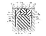
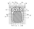
- FIG. 5 is a side sectional view showing a part of the sealing device of FIG. 1 in a used state. It is a side sectional view which shows a part of the sealing device of a comparative example. It is a side sectional view which shows a part of the sealing device of the comparative example in which the outer seal ring is worn.
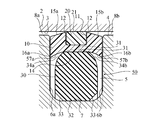
- FIG. 5 is a side sectional view showing a part of a sealing device of a comparative example in which the outer seal ring is further worn. It is a side sectional view which shows a part of the sealing device of FIG. It is a side view of the sealing device which concerns on the modification of embodiment.
- the sealing device 1 includes an inner seal ring 10, an outer seal ring 20, and a back ring 30.
- an inner seal ring 10 In the upper part of FIG. 1, a cross section of the inner seal ring 10, the outer seal ring 20, and the back ring 30 is shown.
- the inner seal ring 10 is a resin ring and has an outer peripheral surface and an inner peripheral surface that are concentric with each other.
- the diameter of the central portion of the outer peripheral surface in the axial direction is large, and the diameter of both ends of the outer peripheral surface in the axial direction is small. Further, the diameter of the central portion of the inner peripheral surface in the axial direction is large, and the diameter of both ends of the inner peripheral surface in the axial direction is small.
- the inner seal ring 10 is formed of a resin having high strength, that is, high rigidity, such as polyamide, polyacetal, polyethylene, polyimide, and PEEK (polyetheretherketone).
- the tensile strength of the material of the inner seal ring 10 is preferably 40 MPa or more.
- a peripheral groove 11 is formed on the outer peripheral surface of the inner seal ring 10.
- the peripheral groove 11 has two side wall surfaces that are parallel to each other and perpendicular to the axial direction of the sealing device 1. Further, the peripheral groove 11 has a uniform depth in the circumferential direction. That is, the peripheral groove 11 has a bottom wall surface that is concentric with the columnar inner peripheral surface 14 of the inner seal ring 10.
- the outer seal ring 20 is fitted in the peripheral groove 11 of the inner seal ring 10. However, the difference between the initial outer radius and the inner radius of the outer seal ring 20 is larger than the depth of the peripheral groove 11, and the radial outer portion 21 of the outer seal ring 20 projects radially outward from the peripheral groove 11.
- the outer seal ring 20 is an endless ring and has an outer peripheral surface and an inner peripheral surface that are concentric with each other. As shown in FIGS. 1 and 3, the outer seal ring 20 has a substantially rectangular cross section. That is, the outer seal ring 20 has a side wall surface parallel to the side wall surface of the peripheral groove 11, and an inner peripheral surface and an outer peripheral surface concentric with the bottom wall surface of the peripheral groove 11.
- the outer peripheral surface of the outer seal ring 20 has a uniform diameter in the axial direction, and the inner peripheral surface also has a uniform diameter in the axial direction.
- the outer portion 21 in the radial direction of the outer seal ring 20 protrudes from the peripheral groove 11, so that the outer peripheral surface of the outer seal ring 20 is arranged radially outside the outermost end 12 of the inner seal ring 10. ing.
- the outer seal ring 20 is formed of a material having elasticity higher than the elasticity of the material of the inner seal ring 10.
- the outer seal ring 20 may be formed of an elastomer.
- the outer seal ring 20 is made of a material having a coefficient of friction much smaller than that of the material of the inner seal ring 10.
- Such materials include, for example, polytetrafluoroethylene (PTFE), perfluoroalkoxy alkane resin (PFA), tetrafluoroethylene / hexafluoropropylene copolymer (FEP), tetrafluoroethylene / ethylene copolymer (ETFE). , Urethane, or polyamide.
- the back ring 30 is an endless ring arranged inside the inner seal ring 10 in the radial direction, and has an outer peripheral surface 31 and an inner peripheral surface 32 that are concentric with each other.
- the back ring 30 is formed of a material having elasticity higher than the elasticity of the material of the inner seal ring 10.
- the buck ring 30 is made of elastomer or urethane.
- the sealing device 1 is used as a piston seal for a hydraulic cylinder.
- the hydraulic cylinder has a fixed cylinder tube (outer member) 2 and a piston (inner member) 4 arranged inside the hole of the cylinder tube 2.
- the piston 4 reciprocates with respect to the cylinder tube 2 along the axial direction of the piston 4 (horizontal direction in FIG. 3).
- the cylinder tube 2 and the piston 4 are made of a material having a rigidity higher than that of the sealing device 1, for example, metal.
- a peripheral groove 5 is formed on the outer peripheral surface of the piston 4.
- the peripheral groove 5 has two side wall surfaces 6a and 6b that are parallel to each other and perpendicular to the axial direction of the piston 4.
- the distance between the side wall surfaces 6a and 6b is larger than the maximum axial length of the sealing device 1 (the distance between the two side wall surfaces of the inner seal ring 10).
- the peripheral groove 5 has a uniform depth over the entire circumferential direction. That is, the peripheral groove 5 has a bottom wall surface 7 that is concentric with the outer peripheral surface of the piston 4.
- the sealing device 1 is arranged in the peripheral groove 5 of the piston 4 and is brought into contact with the inner peripheral surface 3 of the hole of the cylinder tube 2 to separate one space from the other space.
- the left side of the sealing device 1 is one oil storage space
- the right side of the sealing device 1 is the other oil storage space. Is assumed to be.
- the inner diameter of the hole of the cylinder tube 2 is larger than the outer diameter of the piston 4, so that the gap 8a on the oil storage space side between the inner peripheral surface 3 of the hole of the cylinder tube 2 and the outer peripheral surface of the piston 4 A gap 8b on the oil storage space side of the other is provided.
- the sealing device 1 regulates oil leakage from the gap 8a to the gap 8b and oil leakage in the opposite direction.
- the inner peripheral surface 32 of the back ring 30 arranged radially inside the inner seal ring 10 is the bottom wall surface of the peripheral groove 5 of the piston 4. Face contact with 7.
- the outer peripheral surface 31 of the back ring 30 comes into surface contact with the columnar inner peripheral surface 14 of the inner seal ring 10.
- the back ring 30 having elasticity higher than the elasticity of the inner seal ring 10 is compressed between the inner peripheral surface 14 of the inner seal ring 10 and the bottom wall surface 7 of the peripheral groove 5 of the piston 4. Therefore, the back ring 30 applies a pressing force that the inner seal ring 10 and thus the outer seal ring 20 expands radially outward to the inner seal ring 10 and thus the outer seal ring 20.
- the outermost end 12 of the inner seal ring 10 does not come into contact with the inner peripheral surface 3 of the hole of the cylinder tube 2, but the outer seal is arranged radially outside the outermost end 12 of the inner seal ring 10.
- the outer peripheral surface of the ring 20 is brought into surface contact with the inner peripheral surface 3 of the hole of the cylinder tube 2.
- the outer seal ring 20 is compressed between the bottom wall surface of the peripheral groove 11 of the inner seal ring 10 and the inner peripheral surface 3 of the hole of the cylinder tube 2.
- the outer peripheral surface of the outer seal ring 20 slides with respect to the inner peripheral surface 3 as the piston 4 reciprocates.
- Inclined surfaces 33 are formed at both ends of the inner peripheral surface 32 of the buckling 30 in the axial direction.
- the inclined surface 33 facilitates arranging the buckling 30 around the piston 4 and deploying it inside the peripheral groove 5.
- the outer peripheral surface 31 of the buck ring 30 may have a uniform diameter along the axial direction.
- inclined surfaces 34a and 34b are formed at least at both ends in the axial direction of the outer peripheral surface 31, and each of the inclined surfaces 34a and 34b of the buckling 30 has a diameter smaller as the distance from the center in the axial direction increases.
- the inclined surfaces 34a and 34b are curved in an arc shape when viewed from the side, but may be a straight line.
- the outer peripheral surface 31 in the initial state, as shown by the virtual line in FIG. 3, the outer peripheral surface 31 has a substantially semicircular contour, and both ends thereof are inclined surfaces 34a and 34b having an arc shape.
- the central portion of the outer peripheral surface 31 in the axial direction is compressed by the inner peripheral surface 14 of the inner seal ring 10.
- the outer seal ring 20 and the back ring 30 are endless rings, while the inner seal ring 10 is a ring formed by abutting two ends 10A and 10B (see FIGS. 1 and 2) of a rod. .. Therefore, the inner seal ring 10 having high rigidity can be easily arranged in the peripheral groove 5 of the piston 4.
- the shapes of the ends 10A and 10B are known as disclosed in FIG. 9 of Patent Document 1.
- the shape of the end portions 10A and 10B of the embodiment is an example, and the shape of the end portion of the inner seal ring 10 is not limited to the shape shown in the figure, and may be a straight cut, a bias cut, or another cut. May be good.
- inclined surfaces 15a and 15b are formed at both ends of the outer peripheral surface of the inner seal ring 10 in the axial direction.
- Each of the inclined surfaces 15a and 15b has a diameter that becomes smaller as the distance from the center in the axial direction increases. Therefore, as will be described later, after the outer portion 21 of the outer seal ring 20 is worn, it takes a certain amount of time for the entire outer peripheral surface of the inner seal ring 10 to come into contact with the inner peripheral surface 3 of the hole of the cylinder tube 2. ..
- Protruding ring portions 16a and 16b protruding inward in the radial direction are formed at both ends of the inner peripheral surface 14 of the inner seal ring 10 in the axial direction.
- the protruding ring portions 16a and 16b each have a linear inclined surface 17a and 17b when viewed from the side, and each of the inclined surfaces 17a and 17b has a diameter smaller as the distance from the center in the axial direction increases.
- the outer peripheral surface 31 of the back ring 30 is brought into surface contact with the inner peripheral surface 14 of the inner seal ring 10.
- FIG. 4 shows a sealing device 40 in a used state according to a comparative example.
- the entire inner peripheral surface 14 of the inner seal ring 10 of the sealing device 40 is a cylindrical surface and has a uniform diameter in the axial direction. That is, the inner peripheral surface 14 of the inner seal ring 10 of the sealing device 40 is not provided with protruding ring portions 16a and 16b that regulate the movement of the back ring 30 in the axial direction.
- Other features of the sealing device 40 are the same as those of the sealing device 1 according to the embodiment.
- the outer peripheral surface of the inner seal ring 10 also wears by sliding with respect to the inner peripheral surface 3 of the hole of the cylinder tube 2.
- the piston 4 since the protruding ring portions 16a and 16b for restricting the movement of the back ring 30 in the axial direction are not provided on the inner peripheral surface 14 of the inner seal ring 10, the piston 4 reciprocates. Therefore, the buck ring 30 is biased in the axial direction in the peripheral groove 5 of the piston 4.
- FIG. 6 shows a state in which the buck ring 30 is close to one side wall surface 6b of the peripheral groove 5. Since the back ring 30 applies a pressing force that the inner seal ring 10 expands radially outward to the inner seal ring 10, the end 41 of the inner seal ring 10 near the side wall surface 6b of the peripheral groove 5 is a biased back. Pressed by the ring 30, it is greatly elastically deformed outward in the radial direction, and the wide area of the surface 45b, which was the inclined surface 15b of the outer peripheral surface of the inner seal ring 10, comes into contact with the inner peripheral surface 3 of the hole of the cylinder tube 2. To do. In this case, the cylinder tube 2 gives a large sliding resistance to the inner seal ring 10 and thus the piston 4.
- the wear of the surface 45b of the inner seal ring 10 is accelerated. Further, in the contact region 42 between the end 41 of the inner seal ring 10 and the buck ring 30, the compressed state of the buck ring 30 is weakened, so that there is a concern that the sealing performance of the sealing device 40 may be deteriorated in the contact region 42.
- the protruding ring portions 16a and 16b formed at both ends of the inner peripheral surface 14 of the inner seal ring 10 in the axial direction restrict the movement of the buck ring 30 in the axial direction. .. Therefore, as shown in FIG. 7, even if the outer seal ring 20 is worn, the back ring 30 is prevented from being displaced in the axial direction in the peripheral groove 5 of the piston 4. Therefore, the local wear of the outer peripheral surface of the inner seal ring 10 is not accelerated, the elastic deformation of the end portion of the inner seal ring 10 in the axial direction is suppressed, and the deterioration of the sealing performance of the sealing device 1 is also suppressed. Will be done.
- inclined surfaces 34a and 34b are formed at least at both ends of the outer peripheral surface 31 of the buckling 30 in the axial direction, and each of the inclined surfaces 34a and 34b becomes smaller as the distance from the center in the axial direction increases. Has a diameter. Therefore, the buck ring 30 can be easily arranged inside the inner seal ring 10 in which the protruding ring portions 16a and 16b are formed on the inner peripheral surface 14, and the buck ring 30 can be positioned with respect to the inner seal ring 10. It's easy.
- each of the protruding ring portions 16a and 16b has an inner diameter that is smaller as the distance from the center in the axial direction increases. Therefore, when the buck ring 30 moves in the axial direction, the outer peripheral surface 31 of the back ring 30 easily comes into surface contact with the protruding ring portions 16a and 16b of the inner peripheral surface 14 of the inner seal ring 10, so that the sealing device 1 Sealing performance is ensured.
- the protruding ring portions 16a and 16b of the inner peripheral surface 14 of the inner seal ring 10 have inclined surfaces 17a and 17b that are linear when viewed from the side, respectively.
- the protruding ring portions 16a and 16b of the inner peripheral surface 14 of the inner seal ring 10 have arcuate inclined surfaces 57a and 57b when viewed from the side, respectively. You may have.
- Each of the inclined surfaces 57a and 57b has a diameter smaller as the distance from the center in the axial direction increases.
- the shapes of the protruding ring portions 16a and 16b are not limited to those shown in the drawing, and may be other shapes.
- the sealing device 1 is used as a piston seal of a hydraulic cylinder, and in the hydraulic cylinder, the piston 4 which is an inner member moves with respect to the cylinder tube 2 which is a fixed outer member. It may be used for other types of hydraulic or hydraulic equipment.
- the inner member to which the sealing device 1 is deployed may be fixed, and the outer member may reciprocate with respect to the inner member. Alternatively, both the inner member and the outer member may be moved so that the inner member and the outer member move relatively back and forth.
- a sealing device that is arranged in a peripheral groove of an inner member that reciprocates relative to an outer member, is brought into contact with the inner peripheral surface of a hole of the outer member, and separates one space from the other.
- An outer peripheral surface having a peripheral groove, a resin inner seal ring having an inner peripheral surface, and The outer seal ring has elasticity higher than the elasticity of the material of the inner seal ring and is fitted in the peripheral groove of the inner seal ring, and is radially outside from the peripheral groove of the inner seal ring.
- An outer seal ring having an outer portion that protrudes into the outer member and is slidably brought into contact with the inner peripheral surface of the hole of the outer member.
- a sealing device characterized in that protruding ring portions that project inward in the radial direction and regulate the movement of the buck ring in the axial direction are formed at both ends of the inner peripheral surface of the inner seal ring in the axial direction. ..
- the buck ring has an outer peripheral surface that is brought into surface contact with the inner peripheral surface of the inner seal ring.
- a sealing device arranged in a peripheral groove of an inner member that reciprocates relative to an outer member.
- An outer peripheral surface having a peripheral groove, a resin inner seal ring having an inner peripheral surface, and
- the outer seal ring has elasticity higher than the elasticity of the material of the inner seal ring and is fitted in the peripheral groove of the inner seal ring, and is radially outside from the peripheral groove of the inner seal ring.
- an outer seal ring that has an outer part that protrudes into A buckling that has elasticity higher than the elasticity of the material of the inner seal ring, is arranged inside the inner seal ring in the radial direction, and has an outer peripheral surface that is brought into surface contact with the inner peripheral surface of the inner seal ring.
- a sealing device characterized in that it is brought into surface contact with the inner peripheral surface of the inner seal ring.
- the buck ring can be easily arranged inside the inner seal ring having the protruding ring portion formed on the inner peripheral surface in the radial direction, and the positioning of the buck ring with respect to the inner seal ring is also easy.
Landscapes
- Engineering & Computer Science (AREA)
- General Engineering & Computer Science (AREA)
- Mechanical Engineering (AREA)
- Physics & Mathematics (AREA)
- Fluid Mechanics (AREA)
- Sealing Devices (AREA)
Abstract
Description
周溝を有する外周面と、内周面を有する樹脂製のインナーシールリングと、
前記インナーシールリングの材料の弾性よりも高い弾性を有しており、前記インナーシールリングの前記周溝内に嵌め込まれたアウターシールリングであって、前記インナーシールリングの前記周溝から径方向外側に突出して前記外側部材の前記孔の前記内周面に摺動可能に接触させられる外側部分を有するアウターシールリングと、
前記インナーシールリングの材料の弾性よりも高い弾性を有しており、前記インナーシールリングの径方向内側に配置され、前記インナーシールリングの前記内周面と前記内側部材の前記周溝の底壁面との間で圧縮させられるバックリングとを有し、
前記インナーシールリングの前記外周面の軸線方向の両端部に傾斜面が形成され、前記傾斜面は、軸線方向中央から離れるほど小さい直径を有し、
前記インナーシールリングの前記内周面の軸線方向の両端部には、径方向内側に突出し、前記バックリングの軸線方向の移動を規制する突出環部が形成されている
ことを特徴とする密封装置。
前記インナーシールリングの前記突出環部の間で、前記バックリングの前記外周面が前記インナーシールリングの前記内周面に面接触させられる
ことを特徴とする条項1に記載の密封装置。
周溝を有する外周面と、内周面を有する樹脂製のインナーシールリングと、
前記インナーシールリングの材料の弾性よりも高い弾性を有しており、前記インナーシールリングの前記周溝内に嵌め込まれたアウターシールリングであって、前記インナーシールリングの前記周溝から径方向外側に突出する外側部分を有するアウターシールリングと、
前記インナーシールリングの材料の弾性よりも高い弾性を有しており、前記インナーシールリングの径方向内側に配置され、前記インナーシールリングの前記内周面に面接触させられる外周面を有するバックリングとを有し、
前記インナーシールリングの前記外周面の軸線方向の両端部に傾斜面が形成され、前記傾斜面は、軸線方向中央から離れるほど小さい直径を有し、
前記インナーシールリングの前記内周面の軸線方向の両端部には、径方向内側に突出する突出環部が形成されており、これらの突出環部の間で、前記バックリングの前記外周面が前記インナーシールリングの前記内周面に面接触させられる
ことを特徴とする密封装置。
ことを特徴とする条項1から3のいずれか1項に記載の密封装置。
ことを特徴とする条項1から4のいずれか1項に記載の密封装置。
2 シリンダチューブ(外側部材)
3 内周面
4 ピストン(内側部材)
5 周溝
10 インナーシールリング
11 周溝
14 内周面
15a,15b 傾斜面
16a,16b 突出環部
20 アウターシールリング
21 外側部分
30 バックリング
31 外周面
32 内周面
33 傾斜面
34a,34b 傾斜面
Claims (6)
- 外側部材に相対的に往復する内側部材の周溝内に配置され、前記外側部材の孔の内周面に接触させられて、一方の空間と他方の空間を隔てる密封装置であって、
周溝を有する外周面と、内周面を有する樹脂製のインナーシールリングと、
前記インナーシールリングの材料の弾性よりも高い弾性を有しており、前記インナーシールリングの前記周溝内に嵌め込まれたアウターシールリングであって、前記インナーシールリングの前記周溝から径方向外側に突出して前記外側部材の前記孔の前記内周面に摺動可能に接触させられる外側部分を有するアウターシールリングと、
前記インナーシールリングの材料の弾性よりも高い弾性を有しており、前記インナーシールリングの径方向内側に配置され、前記インナーシールリングの前記内周面と前記内側部材の前記周溝の底壁面との間で圧縮させられるバックリングとを有し、
前記インナーシールリングの前記外周面の軸線方向の両端部に傾斜面が形成され、前記傾斜面は、軸線方向中央から離れるほど小さい直径を有し、
前記インナーシールリングの前記内周面の軸線方向の両端部には、径方向内側に突出し、前記バックリングの軸線方向の移動を規制する突出環部が形成されている
ことを特徴とする密封装置。 - 前記バックリングの外周面の少なくとも軸線方向の両端部に傾斜面が形成され、前記バックリングの前記傾斜面は、軸線方向中央から離れるほど小さい直径を有する
ことを特徴とする請求項1に記載の密封装置。 - 前記突出環部は、軸線方向中央から離れるほど小さい内径を有する
ことを特徴とする請求項1または2に記載の密封装置。 - 外側部材に相対的に往復する内側部材の周溝内に配置される密封装置であって、
周溝を有する外周面と、内周面を有する樹脂製のインナーシールリングと、
前記インナーシールリングの材料の弾性よりも高い弾性を有しており、前記インナーシールリングの前記周溝内に嵌め込まれたアウターシールリングであって、前記インナーシールリングの前記周溝から径方向外側に突出する外側部分を有するアウターシールリングと、
前記インナーシールリングの材料の弾性よりも高い弾性を有しており、前記インナーシールリングの径方向内側に配置され、前記インナーシールリングの前記内周面に面接触させられる外周面を有するバックリングとを有し、
前記インナーシールリングの前記外周面の軸線方向の両端部に傾斜面が形成され、前記傾斜面は、軸線方向中央から離れるほど小さい直径を有し、
前記インナーシールリングの前記内周面の軸線方向の両端部には、径方向内側に突出する突出環部が形成されており、これらの突出環部の間で、前記バックリングの前記外周面が前記インナーシールリングの前記内周面に面接触させられる
ことを特徴とする密封装置。 - 前記バックリングの外周面の少なくとも軸線方向の両端部に傾斜面が形成され、前記バックリングの前記傾斜面は、軸線方向中央から離れるほど小さい直径を有する
ことを特徴とする請求項4に記載の密封装置。 - 前記突出環部は、軸線方向中央から離れるほど小さい内径を有する
ことを特徴とする請求項4または5に記載の密封装置。
Priority Applications (5)
| Application Number | Priority Date | Filing Date | Title |
|---|---|---|---|
| EP20814465.9A EP3978786A4 (en) | 2019-05-27 | 2020-04-24 | SEALING DEVICE |
| US17/606,494 US20220205537A1 (en) | 2019-05-27 | 2020-04-24 | Sealing device |
| CN202080034250.0A CN113874642A (zh) | 2019-05-27 | 2020-04-24 | 密封装置 |
| KR1020217035724A KR20210148276A (ko) | 2019-05-27 | 2020-04-24 | 밀봉 장치 |
| JP2021522715A JPWO2020241135A1 (ja) | 2019-05-27 | 2020-04-24 |
Applications Claiming Priority (2)
| Application Number | Priority Date | Filing Date | Title |
|---|---|---|---|
| JP2019-098234 | 2019-05-27 | ||
| JP2019098234 | 2019-05-27 |
Publications (1)
| Publication Number | Publication Date |
|---|---|
| WO2020241135A1 true WO2020241135A1 (ja) | 2020-12-03 |
Family
ID=73554046
Family Applications (1)
| Application Number | Title | Priority Date | Filing Date |
|---|---|---|---|
| PCT/JP2020/017589 Ceased WO2020241135A1 (ja) | 2019-05-27 | 2020-04-24 | 密封装置 |
Country Status (6)
| Country | Link |
|---|---|
| US (1) | US20220205537A1 (ja) |
| EP (1) | EP3978786A4 (ja) |
| JP (1) | JPWO2020241135A1 (ja) |
| KR (1) | KR20210148276A (ja) |
| CN (1) | CN113874642A (ja) |
| WO (1) | WO2020241135A1 (ja) |
Families Citing this family (3)
| Publication number | Priority date | Publication date | Assignee | Title |
|---|---|---|---|---|
| WO2024182709A1 (en) * | 2023-03-01 | 2024-09-06 | A.W. Chesterton Company | Anti-rotational cap seal |
| FR3163986A1 (fr) * | 2024-06-28 | 2026-01-02 | Compagnie Generale Des Etablissements Michelin | Joint d’étanchéité de tige à la géométrie optimisée |
| FR3163985A1 (fr) * | 2024-06-28 | 2026-01-02 | Compagnie Generale Des Etablissements Michelin | Joint d’étanchéité de piston à la géométrie optimisée |
Citations (5)
| Publication number | Priority date | Publication date | Assignee | Title |
|---|---|---|---|---|
| US2784013A (en) * | 1953-12-21 | 1957-03-05 | Bendix Aviat Corp | Hydraulic seal |
| US2968501A (en) * | 1957-04-18 | 1961-01-17 | A P D Co | Fluid seal |
| US4889351A (en) * | 1988-05-12 | 1989-12-26 | Frost Stanley A | Hydraulic seal |
| JP6371570B2 (ja) | 2014-02-25 | 2018-08-08 | Nok株式会社 | 密封装置 |
| JP2018179141A (ja) * | 2017-04-13 | 2018-11-15 | Nok株式会社 | 密封装置 |
Family Cites Families (10)
| Publication number | Priority date | Publication date | Assignee | Title |
|---|---|---|---|---|
| GB1074756A (en) * | 1965-06-24 | 1967-07-05 | Minnesota Rubber Co | Sealing device between relatively movable surfaces |
| US4101140A (en) * | 1972-03-23 | 1978-07-18 | Tetrafluor, Inc. | Peripherally grooved seal |
| GB1550293A (en) * | 1976-11-22 | 1979-08-08 | Caterpillar Tractor Co | Shaft seal |
| JPS5959573U (ja) * | 1982-10-13 | 1984-04-18 | 三菱電線工業株式会社 | シ−ル装置 |
| US5092610A (en) * | 1990-11-15 | 1992-03-03 | Itt Corporation | High pressure piston seal |
| DE19925083A1 (de) * | 1999-06-01 | 2000-12-14 | Festo Ag & Co | Kolben für einen Arbeitszylinder und Verfahren zu seiner Herstellung |
| JP2005221028A (ja) * | 2004-02-06 | 2005-08-18 | Nok Corp | 密封装置 |
| JP5177391B2 (ja) * | 2008-03-10 | 2013-04-03 | いすゞ自動車株式会社 | ピストンシール構造 |
| JP5226765B2 (ja) * | 2010-01-18 | 2013-07-03 | 三菱電線工業株式会社 | 密封構造 |
| WO2016092932A1 (ja) * | 2014-12-12 | 2016-06-16 | Nok株式会社 | 密封装置 |
-
2020
- 2020-04-24 EP EP20814465.9A patent/EP3978786A4/en not_active Withdrawn
- 2020-04-24 CN CN202080034250.0A patent/CN113874642A/zh active Pending
- 2020-04-24 WO PCT/JP2020/017589 patent/WO2020241135A1/ja not_active Ceased
- 2020-04-24 KR KR1020217035724A patent/KR20210148276A/ko not_active Ceased
- 2020-04-24 US US17/606,494 patent/US20220205537A1/en not_active Abandoned
- 2020-04-24 JP JP2021522715A patent/JPWO2020241135A1/ja active Pending
Patent Citations (5)
| Publication number | Priority date | Publication date | Assignee | Title |
|---|---|---|---|---|
| US2784013A (en) * | 1953-12-21 | 1957-03-05 | Bendix Aviat Corp | Hydraulic seal |
| US2968501A (en) * | 1957-04-18 | 1961-01-17 | A P D Co | Fluid seal |
| US4889351A (en) * | 1988-05-12 | 1989-12-26 | Frost Stanley A | Hydraulic seal |
| JP6371570B2 (ja) | 2014-02-25 | 2018-08-08 | Nok株式会社 | 密封装置 |
| JP2018179141A (ja) * | 2017-04-13 | 2018-11-15 | Nok株式会社 | 密封装置 |
Non-Patent Citations (1)
| Title |
|---|
| See also references of EP3978786A4 |
Also Published As
| Publication number | Publication date |
|---|---|
| JPWO2020241135A1 (ja) | 2020-12-03 |
| US20220205537A1 (en) | 2022-06-30 |
| KR20210148276A (ko) | 2021-12-07 |
| CN113874642A (zh) | 2021-12-31 |
| EP3978786A1 (en) | 2022-04-06 |
| EP3978786A4 (en) | 2022-06-22 |
Similar Documents
| Publication | Publication Date | Title |
|---|---|---|
| US11536373B2 (en) | Seal assemblies and related methods | |
| EP3312482B1 (en) | Seal assemblies for extreme temperatures and related methods | |
| US11428321B2 (en) | Seals | |
| US10989305B2 (en) | Axial and radial floating seals | |
| WO2020241135A1 (ja) | 密封装置 | |
| US8739684B2 (en) | Fluid pressure apparatus | |
| JP6017738B1 (ja) | 密封装置 | |
| KR101802897B1 (ko) | 유체압 기기 | |
| JP7598863B2 (ja) | 複数部品シール組立品 | |
| US6517081B2 (en) | Machinery seal | |
| KR20210002624A (ko) | 피스톤 링 및 압축기 | |
| JP6934387B2 (ja) | 密封装置 | |
| JP2010196751A (ja) | 密封装置 | |
| KR19990022874A (ko) | 밀봉장치 | |
| KR20170003399U (ko) | 밀봉 장치 | |
| JP3966901B2 (ja) | シールリング | |
| KR101694641B1 (ko) | 실링조립체 및 이를 구비한 터빈밸브 유압액추에이터 실린더어셈블리 | |
| JP2011231781A (ja) | 摺動用シール材 | |
| JP2023516701A (ja) | ピストンリングアセンブリ、ピストン圧縮機、および、圧縮室を密閉する方法 | |
| JPWO2020241135A5 (ja) | ||
| CN111630305A (zh) | 密封件 | |
| KR20180075645A (ko) | 축 및 밀봉구조 | |
| JP6128596B2 (ja) | 密封装置 | |
| WO2012132659A1 (ja) | 密封装置 | |
| JP7203971B2 (ja) | 密封装置 |
Legal Events
| Date | Code | Title | Description |
|---|---|---|---|
| 121 | Ep: the epo has been informed by wipo that ep was designated in this application |
Ref document number: 20814465 Country of ref document: EP Kind code of ref document: A1 |
|
| ENP | Entry into the national phase |
Ref document number: 2021522715 Country of ref document: JP Kind code of ref document: A |
|
| ENP | Entry into the national phase |
Ref document number: 20217035724 Country of ref document: KR Kind code of ref document: A |
|
| NENP | Non-entry into the national phase |
Ref country code: DE |
|
| ENP | Entry into the national phase |
Ref document number: 2020814465 Country of ref document: EP Effective date: 20220103 |