WO2020241593A1 - 燃料電池装置 - Google Patents
燃料電池装置 Download PDFInfo
- Publication number
- WO2020241593A1 WO2020241593A1 PCT/JP2020/020609 JP2020020609W WO2020241593A1 WO 2020241593 A1 WO2020241593 A1 WO 2020241593A1 JP 2020020609 W JP2020020609 W JP 2020020609W WO 2020241593 A1 WO2020241593 A1 WO 2020241593A1
- Authority
- WO
- WIPO (PCT)
- Prior art keywords
- fuel cell
- fuel
- utilization rate
- current
- relational expression
- Prior art date
- Legal status (The legal status is an assumption and is not a legal conclusion. Google has not performed a legal analysis and makes no representation as to the accuracy of the status listed.)
- Ceased
Links
Images



Classifications
-
- H—ELECTRICITY
- H01—ELECTRIC ELEMENTS
- H01M—PROCESSES OR MEANS, e.g. BATTERIES, FOR THE DIRECT CONVERSION OF CHEMICAL ENERGY INTO ELECTRICAL ENERGY
- H01M8/00—Fuel cells; Manufacture thereof
- H01M8/10—Fuel cells with solid electrolytes
- H01M8/12—Fuel cells with solid electrolytes operating at high temperature, e.g. with stabilised ZrO2 electrolyte
-
- H—ELECTRICITY
- H01—ELECTRIC ELEMENTS
- H01M—PROCESSES OR MEANS, e.g. BATTERIES, FOR THE DIRECT CONVERSION OF CHEMICAL ENERGY INTO ELECTRICAL ENERGY
- H01M8/00—Fuel cells; Manufacture thereof
- H01M8/04—Auxiliary arrangements, e.g. for control of pressure or for circulation of fluids
- H01M8/04298—Processes for controlling fuel cells or fuel cell systems
- H01M8/04694—Processes for controlling fuel cells or fuel cell systems characterised by variables to be controlled
- H01M8/04746—Pressure; Flow
- H01M8/04753—Pressure; Flow of fuel cell reactants
-
- G—PHYSICS
- G05—CONTROLLING; REGULATING
- G05B—CONTROL OR REGULATING SYSTEMS IN GENERAL; FUNCTIONAL ELEMENTS OF SUCH SYSTEMS; MONITORING OR TESTING ARRANGEMENTS FOR SUCH SYSTEMS OR ELEMENTS
- G05B15/00—Systems controlled by a computer
- G05B15/02—Systems controlled by a computer electric
-
- H—ELECTRICITY
- H01—ELECTRIC ELEMENTS
- H01M—PROCESSES OR MEANS, e.g. BATTERIES, FOR THE DIRECT CONVERSION OF CHEMICAL ENERGY INTO ELECTRICAL ENERGY
- H01M8/00—Fuel cells; Manufacture thereof
- H01M8/04—Auxiliary arrangements, e.g. for control of pressure or for circulation of fluids
- H01M8/04082—Arrangements for control of reactant parameters, e.g. pressure or concentration
- H01M8/04089—Arrangements for control of reactant parameters, e.g. pressure or concentration of gaseous reactants
-
- H—ELECTRICITY
- H01—ELECTRIC ELEMENTS
- H01M—PROCESSES OR MEANS, e.g. BATTERIES, FOR THE DIRECT CONVERSION OF CHEMICAL ENERGY INTO ELECTRICAL ENERGY
- H01M8/00—Fuel cells; Manufacture thereof
- H01M8/04—Auxiliary arrangements, e.g. for control of pressure or for circulation of fluids
- H01M8/04298—Processes for controlling fuel cells or fuel cell systems
- H01M8/04313—Processes for controlling fuel cells or fuel cell systems characterised by the detection or assessment of variables; characterised by the detection or assessment of failure or abnormal function
- H01M8/04537—Electric variables
-
- H—ELECTRICITY
- H01—ELECTRIC ELEMENTS
- H01M—PROCESSES OR MEANS, e.g. BATTERIES, FOR THE DIRECT CONVERSION OF CHEMICAL ENERGY INTO ELECTRICAL ENERGY
- H01M8/00—Fuel cells; Manufacture thereof
- H01M8/04—Auxiliary arrangements, e.g. for control of pressure or for circulation of fluids
- H01M8/04298—Processes for controlling fuel cells or fuel cell systems
- H01M8/04313—Processes for controlling fuel cells or fuel cell systems characterised by the detection or assessment of variables; characterised by the detection or assessment of failure or abnormal function
- H01M8/04537—Electric variables
- H01M8/04574—Current
- H01M8/04582—Current of the individual fuel cell
-
- H—ELECTRICITY
- H01—ELECTRIC ELEMENTS
- H01M—PROCESSES OR MEANS, e.g. BATTERIES, FOR THE DIRECT CONVERSION OF CHEMICAL ENERGY INTO ELECTRICAL ENERGY
- H01M8/00—Fuel cells; Manufacture thereof
- H01M8/04—Auxiliary arrangements, e.g. for control of pressure or for circulation of fluids
- H01M8/04298—Processes for controlling fuel cells or fuel cell systems
- H01M8/04694—Processes for controlling fuel cells or fuel cell systems characterised by variables to be controlled
- H01M8/04746—Pressure; Flow
-
- H—ELECTRICITY
- H01—ELECTRIC ELEMENTS
- H01M—PROCESSES OR MEANS, e.g. BATTERIES, FOR THE DIRECT CONVERSION OF CHEMICAL ENERGY INTO ELECTRICAL ENERGY
- H01M8/00—Fuel cells; Manufacture thereof
- H01M8/04—Auxiliary arrangements, e.g. for control of pressure or for circulation of fluids
- H01M8/04298—Processes for controlling fuel cells or fuel cell systems
- H01M8/04694—Processes for controlling fuel cells or fuel cell systems characterised by variables to be controlled
- H01M8/04858—Electric variables
-
- Y—GENERAL TAGGING OF NEW TECHNOLOGICAL DEVELOPMENTS; GENERAL TAGGING OF CROSS-SECTIONAL TECHNOLOGIES SPANNING OVER SEVERAL SECTIONS OF THE IPC; TECHNICAL SUBJECTS COVERED BY FORMER USPC CROSS-REFERENCE ART COLLECTIONS [XRACs] AND DIGESTS
- Y02—TECHNOLOGIES OR APPLICATIONS FOR MITIGATION OR ADAPTATION AGAINST CLIMATE CHANGE
- Y02E—REDUCTION OF GREENHOUSE GAS [GHG] EMISSIONS, RELATED TO ENERGY GENERATION, TRANSMISSION OR DISTRIBUTION
- Y02E60/00—Enabling technologies; Technologies with a potential or indirect contribution to GHG emissions mitigation
- Y02E60/30—Hydrogen technology
- Y02E60/50—Fuel cells
Definitions
- This disclosure relates to a fuel cell device.
- the solid oxide fuel cell device uses raw fuel (hydrogen-containing gas) and air (oxygen-containing gas) to generate electricity.
- this fuel cell device is used for small-scale power generation with low power consumption (current value) such as for home use and small-scale business use, it is required power by an external load (hereinafter, also simply referred to as "load”). Fluctuates relatively large. Therefore, in addition to the so-called rated operation, the fuel cell device has a specification (mode) called “load follow-up operation” or “partial load operation” in which the power generation operation is performed at a low current whose power generation current is less than the rated operation.
- mode specification
- Patent Document 1 describes the relationship between the air utilization rate [Ua (%)] of the cell stack and the generated current amount [current value I (A)] during the partial load (load follow-up) operation. It is shown. That is, in the graph showing the correlation between the air utilization rate Ua and the power generation current amount I shown in the figure of Patent Document 1, the rate of increase in the air utilization rate Ua with the increase in the power generation current amount I in response to the load request is shown in the box. Proposals for changing the temperature of the air (oxygen-containing gas) in the body are disclosed.
- Patent Document 2 describes the relationship between the fuel utilization rate [Uf (%)] of the cell stack and the generated current amount [current value I (A)] during the partial load (load tracking) operation. It is shown. That is, in the graph showing the correlation between the fuel utilization rate Uf and the power generation current amount I shown in the figure of Patent Document 1, the rate of increase of the fuel utilization rate Uf with the increase of the power generation current amount I in response to the load request is set to 2.
- a proposal for making a "non-straight line" (non-linear straight line) such as a linear curve or a cubic curve is disclosed.
- the "self-sustaining operation" mode in which the fuel cell device alone can supply power to the load is executed.
- the current increase speed is increased in order to improve the output tracking performance (hereinafter referred to as "load tracking property") to the external load for the purpose of immediately responding to the fluctuation (request) of the external load.
- load tracking property the output tracking performance
- a state in which the amount of air and / or the amount of fuel gas required for power generation is temporarily insufficient in the cell stack may occur, and the fuel cell may be damaged.
- the fuel cell apparatus of the present disclosure includes a fuel cell that generates electricity using a fuel gas and an oxygen-containing gas, an oxygen-containing gas supply unit that supplies the oxygen-containing gas to the fuel cell, and a fuel that supplies the fuel gas to the fuel cell.
- the control device has a plurality of predetermined relational expressions of the power generation amount of the fuel cell and the air utilization rate and / or the fuel utilization rate, and the current increase speed set by the power regulator.
- the selection control for selecting the relational expression is executed based on.
- the fuel cell device 100 of the embodiment shown in FIG. 1 includes a fuel cell module 1 that generates power using a fuel gas and an oxygen-containing gas, an oxygen-containing gas supply unit 13 having an air blower B1 and an air flow path F, and a fuel. Supplement to assist the independent power generation operation of the fuel cell, such as the fuel supply unit 14 having the pump B2 and the raw fuel flow path G, the reforming water supply unit 15 including the reforming water tank 6 and the reforming water pump P1 and the like. Equipped with aircraft.
- the fuel cell device 100 includes a power adjusting device (power conditioner 20) as an auxiliary device for coordinating the power supply to the outside and the system power source, and cooperates with the power conditioner 20 to obtain the above-mentioned fuel.
- a control device 30 for controlling the operation of each auxiliary device that assists the power generation operation of the battery is provided.
- the power conditioner 20 has an ammeter (A ampere), a voltmeter (V volt), and the like.
- the fuel cell device 100 of the present embodiment includes a heat exchanger 2, a heat storage tank 3 (also referred to as a hot water storage tank), a radiator (radiator 4), a flow path pipe connecting them, a heat medium pump P2, and the like. It is equipped with a heat recovery system (heat cycle HC1).
- the fuel cell device 100 shown in FIG. 1 further includes a second heat exchanger 5 (also referred to as a tap water heat exchanger) for heating tap water (tap water) to be supplied to the outside, and the above-mentioned. It is provided with a hot water supply system (heat cycle HC2) including a heat supply pump P3 for taking out a high-temperature heat medium from the heat storage tank 3 and circulating it, a circulation pipe, and the like.
- the fuel cell device may be a so-called monogeneration system that does not supply hot water to the outside.
- the fuel cell device 100 is arranged in a case 40 including each frame 41 and each exterior panel 42 as shown in FIG.
- a plurality of measuring devices, sensors, and the like as described below are provided around the fuel cell module 1 and each auxiliary machine, a flow path, a pipe, and the like in the case 40.
- an air flow meter FM1 such as a flow meter is arranged in the air flow path F of the oxygen-containing gas supply unit 13 that supplies air (oxygen-containing gas) to the fuel cell module 1.
- the air flow meter FM1 measures the flow rate of air supplied to the cell stack 11 per hour.
- a fuel flow meter FM2 such as a flow meter is arranged in the raw fuel flow path G of the fuel supply unit 14 that supplies raw fuel (gas) to the fuel cell module 1.
- the fuel flow meter FM2 measures the flow rate per hour of raw fuel (fuel gas) such as city gas supplied to the reformer 12.
- the fuel cell device 100 may be provided with a plurality of temperature sensors for measuring the temperature of each part of the fuel cell, a temperature measuring device such as a thermistor, a thermometer (not shown), and the like.
- the control device 30 that controls the operation of the fuel cell device 100 as a whole is connected to a storage device and a display device (both not shown), and various components and sensors constituting the fuel cell device 100. , The entire fuel cell apparatus 100 including each of these functional units is controlled and managed. Further, the control device 30 acquires a program stored in a storage device attached to the control device 30 and executes the program to realize various functions related to each part of the fuel cell device 100.
- control device 30 and the other functional unit may be connected by wire or wirelessly.
- the control characteristic of the present embodiment performed by the control device 30 will be described later.
- control device 30 particularly represents the magnitude of the electric power required from the external load, instructions and commands of the external device (water heater 200, etc.) connected to the fuel cell device, and the amount of electric power supplied to the outside.
- the air blower B1 of the oxygen-containing gas supply unit 13 that supplies air to the cell stack 11 based on the measured values of an ammeter, a voltmeter, etc. (VA apparent power, etc.) or the instructions and measured values of the various sensors described above.
- the operation of the fuel pump B2 and the like of the fuel supply unit 14 are controlled.
- the control device 30 controls the operations of the oxygen-containing gas supply unit 13 and the fuel supply unit 14 to obtain an amount of oxygen-containing gas required for operation. Fuel gas is supplied to the fuel cell. As a result, the electric power generated by the fuel cell is supplied to the external load via the electric power regulator (power conditioner 20).
- air flow rate control for operating and increasing / decreasing the “air utilization rate (Ua)” that substitutes for the air flow rate will be described according to the generated current amount [I (A)].
- the control device 30 of the fuel cell device 100 of the first and second embodiments corresponds to an air blower corresponding to the generated current amount I (A) of the fuel cell controlled by the power regulator (hereinafter, power conditioner 20).
- Control B1 controls the air blower B1 according to a preset "air utilization rate" (that is, Ua) corresponding to the generated current amount I (A).
- the "air utilization rate” (Ua) means the ratio of the amount of air used for power generation to the amount of air supplied to the fuel cell.
- control device 30 of the fuel cell device 100 of the embodiment has a plurality of relational expressions between the power generation amount of the fuel cell (fuel cell module 1) and the air utilization rate, and is set by the power conditioner 20.
- the selection control for selecting the relational expression is executed based on the current rise rate. As a result, damage to the fuel cell can be suppressed by selecting and executing an appropriate relational expression according to the current rise rate.
- the "current rise rate” refers to the displacement amount (difference) when the amount of current generated by the fuel cell (generated current amount or current value) changes in the increasing direction per unit time.
- the unit is A (ampere) / sec.
- FIG. 3 is a graph of the first embodiment showing the relationship between the amount of current [I] generated by power generation and the air utilization rate [Ua] in the cell stack of the fuel cell device of the embodiment.
- two types of graphs are shown, a relational expression shown by a solid line and a relational expression shown by a partially broken line.
- the values of the air utilization rate Ua and the current amount I which is the power generation amount, can be appropriately set. Therefore, FIG. 3 shows only an example of the relational expression (graph) between the air utilization rate Ua and the power generation amount (I). Further, the relational expression may have three or more relational expressions.
- the graph shown in FIG. 3 will be used for description.
- An example (displayed with a solid line) is shown. It should be noted that the relational expression is common except for the broken line portion of the first relational expression.
- the curve shown by the broken line in the first relational expression is air other than during "self-sustaining operation" in the event of a power failure or the like, that is, during normal operation (when the "current rise rate” of the present disclosure is slow or low). This is an example of a curve of a graph showing the relationship between the utilization rate Ua and the generated current amount I.
- this [first increase section] is a section in which the air utilization rate Ua is set low at the time of start-up, and then the air utilization rate Ua gradually increases in response to an increase in the current amount I of the fuel cell. is there.
- the amount of excess oxygen-containing gas (air) increases at the time of startup, so that the heat of combustion can be increased and the temperature of the fuel cell can be raised quickly. Therefore, the startup time can be shortened.
- by gradually increasing the air utilization rate Ua as the current amount I increases efficient operation becomes possible while raising the temperature of the fuel cell.
- the air utilization rate Ua has a constant [second constant section].
- This [second fixed section] indicates a section called "rated" in which the output of the fuel cell is at the maximum rated. In the section where the amount of current I is high, efficient operation can be performed by setting the air utilization rate Ua high.
- the [first constant section] in FIG. 3 is the [first increase section], which is a section (current) provided to suppress an increase in the air utilization rate Ua that gradually increases with the increase in the current amount I. Section).
- the air flow rate of the same ratio is increased with respect to the increase of the current amount I, and as a result, there is no slope of the graph curve, that is, the current amount I and the air utilization rate Ua.
- the coefficient of the "linear expression" representing the relationship between the two is the interval of "0 (zero)". The coefficient of the linear equation does not have to be completely 0, it may be almost 0.
- the control device 30 has a current increase speed lower than the predetermined speed at least in the above-mentioned [first fixed section].
- the [first constant section] is a section in which the increase rate of the air utilization rate Ua due to the increase in the current is different from the above-mentioned [first increase section].
- second increasing section it is a section connecting the first fixed section and the second fixed section, and is a coefficient of the "linear equation" representing the relationship between the current amount I and the air utilization rate Ua. Is the "positive (plus)” section.
- the slope of the graph in this section can be set as appropriate, and the slope may be steeper or looser than that of the first increase section.
- the fuel cell device 100 of the present embodiment shifts to the self-sustaining operation mode, and in a state where the current rising speed is set high as described above, the load (output current) is increased by the request of the external load. Even if the amount rises sharply, the amount of air supplied is set to be larger than during normal operation in advance, so the amount of air required for power generation is temporarily insufficient in the cell stack, resulting in a high Ua state. Is suppressed.
- the coefficient of the linear equation representing the relationship between the current amount I and the air utilization rate Ua in the [first fixed section] in FIG. 3 is "negative (minus)", that is, the slope of the graph curve is negative (minus). You may try to take it.
- the increment of the air utilization rate Ua with respect to the current amount I in the [second increase interval] does not necessarily have to be linear (functional), and is a quadratic curve (quadratic function) or a cubic curve (cubic function).
- the graph curve may be non-linear, such as. The same applies to the [first increase section].
- FIG. 3 showing the setting of the air utilization rate Ua of the first embodiment
- FIG. 4 showing the setting of the air utilization rate Ua of the second embodiment
- the difference between the second increasing section in the first relational expression Is a decreasing section
- the value of the air utilization rate Ua in the section called "rated" where the output of the fuel cell is the maximum rating is constant (Fig. 3) or as the current value rises. Is decreasing (Fig. 4).
- the description of the same part as that of the first embodiment will be simplified.
- the [constant section] is set. It is provided.
- the amount of air of the same ratio is increased with respect to the increase in the amount of current I.
- the [constant section] is a section in which the coefficient of the “linear equation” representing the relationship between the current amount I and the air utilization rate Ua is “0 (zero)” without the slope of the graph curve. The coefficient of the linear equation does not have to be completely 0, it may be almost 0.
- control device 30 of the fuel cell device 100 determines the current rise rate at least in the above-mentioned [constant section] when the current rise rate set by the power regulator 20 is the self-sustaining operation mode of a predetermined speed or higher.
- the "second relational expression" ([first constant section]] set so that the air utilization rate Ua is lower than the "first relational expression” (corresponding to the [first increase section]) when the speed is lower than the speed. (Equivalent to) is selected.
- the whole relational expression may be selected, but for example, the relational expression may be selected only for different sections.
- the [constant section] is a section in which the increase rate of the air utilization rate Ua due to the increase in the current is different from the above-mentioned [first increase section].
- the minimum amount of air required for the maximum amount of current I in the fuel cell can be calculated.
- the air utilization rate Ua is calculated so that this amount of air is minimized.
- the air utilization rate Ua in the [second increase section] and [decrease section] is calculated based on the minimum amount of air required for the maximum amount of current I, and is based on the first relational expression. It becomes a continuous falling section. As a result, even if the load (output current) suddenly rises due to the request of the external load, the amount of air required for power generation may be temporarily insufficient in the cell stack, and a high Ua state may occur. , Suppressed.
- the [second increase section] is a section connecting the constant section and the decrease section, and as in the first embodiment, with respect to the increase in the amount of current I.
- This is the section where the air flow rate at a smaller ratio is increased.
- the slope of the graph curve that is, the coefficient of the "linear equation" representing the relationship between the current amount I and the air utilization rate Ua is "positive (plus)".
- the slope of the graph in this section can be set as appropriate, and the slope may be steeper or looser than that of the first increase section.
- the section where the air utilization rate Ua is lowered from the normal operating state that is, a large amount of air is cell-stacked between the [first increasing section] and the [decreasing section].
- relational expression for example, a relational expression regarding the upper limit value of the air utilization rate Ua and a relational expression regarding the upper limit lower limit value of the oxygen-containing gas flow rate may be held.
- a relational expression having priority is appropriately set and the relational expression is selected. You may do it.
- the control device 30 of the fuel cell device 100 of the third embodiment controls the fuel pump B2 in response to the generated current amount I (A) of the fuel cell controlled by the power regulator (hereinafter, power conditioner 20). To do.
- the control device 30 controls the fuel pump B2 according to a preset "fuel utilization rate" (that is, Uf) corresponding to the generated current amount I (A).
- the fuel utilization rate (Uf) means the ratio of the amount of fuel gas used for power generation to the amount of fuel gas supplied to the fuel cell.
- control device 30 of the fuel cell device 100 of the third embodiment stores a plurality of relational expressions of the power generation amount and the fuel utilization rate of the fuel cell (fuel cell module 1), and is set by the power conditioner 20.
- the selection control for selecting the relational expression is executed based on the current rising rate. As a result, damage to the fuel cell can be suppressed by selecting and executing an appropriate relational expression according to the current rise rate.
- the "current rise rate” refers to the displacement amount (difference) when the amount of current generated by the fuel cell (generated current amount or current value) changes in the increasing direction per unit time.
- the unit is A (ampere) / sec.
- FIG. 5 is a graph showing the relationship between the amount of current [I] generated by power generation and the fuel utilization rate [Uf] in the cell stack of the fuel cell device of the third embodiment.
- two types of graphs are shown, a relational expression shown by a solid line and a relational expression shown by a partially broken line.
- the values of the fuel utilization rate Uf and the current amount I which is the amount of power generation, can be appropriately set depending on the size (rated power generation amount) of the fuel cell device and the like. Therefore, FIG. 5 shows only an example of the relational expression (graph) between the fuel utilization rate Uf and the power generation amount (I). Further, the relational expression may have three or more relational expressions.
- the graph shown in FIG. 5 will be used for description.
- An example (displayed with a solid line) is shown. It should be noted that the relational expression is common except for the broken line portion of the third relational expression.
- the curve shown by the broken line of the third relational expression is the fuel other than the "self-sustaining operation" in the event of a power failure or the like, that is, during the normal operation (when the "current rise rate” of the present disclosure is slow or low). This is an example of a curve of a graph showing the relationship between the utilization rate Uf and the generated current amount I.
- this [first increase section] is a section in which the fuel utilization rate Uf is set low at the time of start-up, and then the fuel utilization rate Uf gradually increases in response to an increase in the current amount I of the fuel cell. is there.
- the graph of FIG. 5 has a [second constant section] in which the fuel utilization rate Uf is constant.
- This [second fixed section] indicates a section called "rated" in which the output of the fuel cell is at the maximum rated. As described above, in the section where the current amount I is high, efficient operation can be performed by setting the fuel utilization rate Uf high.
- the [first constant section] in FIG. 5 is the [first increase section], which is a section (current) provided to suppress an increase in the fuel utilization rate Uf that has gradually increased with the increase in the current amount I. Section).
- the [first fixed section] the raw material flow rate of the same ratio is increased with respect to the increase of the current amount I, and as a result, there is no slope of the graph curve, that is, the current amount I and the fuel utilization rate.
- the coefficient of the "linear expression" representing the relationship of Uf is the interval of "0 (zero)". The coefficient of the linear equation does not have to be completely 0, it may be almost 0.
- the control device 30 when the current rise speed set by the power conditioner 20 is the self-sustaining operation mode of the predetermined speed or higher, the control device 30 has a current rise speed lower than the predetermined speed at least in the above-mentioned [first fixed section].
- the [first constant section] is a section in which the rate of increase in the fuel utilization rate Uf due to the increase in current is different from the above-mentioned [first increase section].
- second increase section it is a section connecting the first fixed section and the second fixed section, and is a coefficient of the "linear equation" representing the relationship between the current amount I and the fuel utilization rate Uf. Is the "positive (plus)” section.
- the slope of the graph in this section can be set as appropriate, and the slope may be steeper or looser than that of the first increase section.
- the fuel cell device 100 of the present embodiment shifts to the self-sustaining operation mode, and in a state where the current rising speed is set high as described above, the load (output current) is increased by the request of the external load. Even if the amount rises sharply, the amount of raw fuel supplied is set to be larger than during normal operation in advance, so the amount of fuel gas required for power generation is temporarily insufficient in the cell stack and is high. The occurrence of the Uf state is suppressed.
- the increment of the fuel utilization rate Uf with respect to the current amount I in the [second increase section] in FIG. 5 does not necessarily have to be linear (function), and is a quadratic curve (quadratic function) or a cubic curve (). It may be a non-linear graph curve such as a cubic function). The same applies to the [first increase section].
- relational expression for example, a relational expression regarding the upper limit value of the fuel utilization rate Uf and a relational expression regarding the upper limit value or the lower limit value in the fuel gas flow rate may be held.
- a relational expression that gives priority as appropriate is set. The relational expression may be selected.
- air flow rate control that operates and increases / decreases the “air utilization rate (Ua)” that substitutes for the air flow rate according to the generated current amount [I (A)] and the generated current amount.
- fuel gas flow rate control that operates and increases / decreases the “fuel utilization rate (Uf)” that substitutes for the fuel gas flow rate has been explained individually. It can be done at the same time.
- the fuel cell device of the present disclosure it is possible to provide a fuel cell device having improved durability in which damage to the fuel cell is suppressed while performing self-sustaining operation.
- Fuel cell module 11 Cell stack 12 Reformer 20 Power conditioner 30 Control device 13 Oxygen-containing gas supply section 14 Fuel supply section 100 Fuel cell device F Air flow path G Raw fuel flow path B1 Air blower B2 Fuel pump FM1 Air flow rate FM2 fuel flow meter
Landscapes
- Engineering & Computer Science (AREA)
- Chemical & Material Sciences (AREA)
- Life Sciences & Earth Sciences (AREA)
- Manufacturing & Machinery (AREA)
- Sustainable Development (AREA)
- Sustainable Energy (AREA)
- Chemical Kinetics & Catalysis (AREA)
- Electrochemistry (AREA)
- General Chemical & Material Sciences (AREA)
- Physics & Mathematics (AREA)
- General Physics & Mathematics (AREA)
- Automation & Control Theory (AREA)
- General Engineering & Computer Science (AREA)
- Fuel Cell (AREA)
Abstract
本開示の燃料電池装置は、燃料電池モジュール(1)に空気を供給する酸素含有ガス供給部(13)と、燃料電池に燃料ガスを供給する燃料供給部(14)と、発電した電流の負荷への供給を調整する電力調整装置(20)と、制御装置(30)と、を備える。制御装置(30)は、予め定められた、燃料電池が発電する電流量〔I〕と、空気利用率〔Ua〕および/または燃料利用率〔Uf〕と、の関係式を複数有しており、停電時等の自立運転時に、発電電流量を増量しようとする際、電力調整装置(20)で設定された電流上昇速度に基づいて関係式を選択する。
Description
本開示は、燃料電池装置に関する。
固体酸化物形の燃料電池装置(SOFC)は、原燃料(水素含有ガス)および空気(酸素含有ガス)を用いて発電を行なう。この燃料電池装置は、家庭用途や小規模事業所用途等、使用電力(電流値)の低い、小規模な発電に利用される場合、外部負荷(以下、単に「負荷」ともいう)による要求電力は、比較的大きく変動する。そのため、燃料電池装置は、いわゆる定格運転の他に、発電電流が定格運転未満の低電流で発電運転を行なう、「負荷追従運転」または「部分負荷運転」と呼ばれる仕様(モード)を備える。
この部分負荷運転に関し、特許文献1には、部分負荷(負荷追従)運転中の、セルスタックの空気利用率〔Ua(%)〕と発電電流量〔電流値I(A)〕との関係が示されている。すなわち、特許文献1の図に示す、空気利用率Uaと発電電流量Iの相関を表すグラフにおいて、負荷の要求に応じた発電電流量Iの増加に伴う空気利用率Uaの増加割合を、筐体内の空気(酸素含有ガス)の温度に応じて変化させる提案が開示されている。
またこの部分負荷運転に関し、特許文献2には、部分負荷(負荷追従)運転中の、セルスタックの燃料利用率〔Uf(%)〕と発電電流量〔電流値I(A)〕との関係が示されている。すなわち、特許文献1の図に示す、燃料利用率Ufと発電電流量Iの相関を表すグラフにおいて、負荷の要求に応じた発電電流量Iの増加に伴う燃料利用率Ufの増加割合を、二次曲線あるいは三次曲線等の「非直線」(非一次直線)状とする提案が開示されている。
燃料電池装置においては、停電や外部電源の喪失等、系統電源と解列した場合、燃料電池装置単体で、負荷に対して電力の供給を行なうことのできる「自立運転」モードが実行される。
この自立運転モードにおいては、外部負荷の変動(要求)に即座に応えることを目的に、外部負荷への出力追従性能(以下、「負荷追従性」という)を引き上げるべく、電流上昇速度を高くする場合がある。この場合に、一時的に、セルスタックの中で、発電に必要な空気の量および/または燃料ガスの量が不足する状態が発生し、燃料電池セルに損傷等が発生するおそれがある。
本開示の燃料電池装置は、燃料ガスと酸素含有ガスとを用いて発電を行なう燃料電池と、燃料電池に酸素含有ガスを供給する酸素含有ガス供給部と、燃料電池に燃料ガスを供給する燃料供給部と、燃料電池で発電した電流の負荷への供給を調整する電力調整装置と、前記酸素含有ガス供給部および/または前記燃料供給部と、前記電力調整装置の動作と、を制御する制御装置と、を備える。
前記制御装置は、予め定められた、前記燃料電池の発電量と、空気利用率および/または燃料利用率と、の関係式を複数有しており、前記電力調整装置で設定された電流上昇速度に基づいて、前記関係式を選択する選択制御を実行する。
前記制御装置は、予め定められた、前記燃料電池の発電量と、空気利用率および/または燃料利用率と、の関係式を複数有しており、前記電力調整装置で設定された電流上昇速度に基づいて、前記関係式を選択する選択制御を実行する。
本開示の目的、特色、および利点は、下記の詳細な説明と図面とからより明確になるであろう。
実施形態の燃料電池装置の概略構成図である。
外装ケース内の燃料電池装置の構成を示す斜視図である。
第1実施形態の燃料電池装置のセルスタックにおける、発電により発生する電流量〔I〕と空気利用率〔Ua〕との関係を示すグラフである。
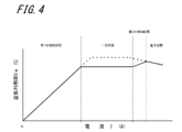
第2実施形態の燃料電池装置のセルスタックにおける、発電により発生する電流量〔I〕と空気利用率〔Ua〕との関係を示すグラフである。
第3実施形態の燃料電池装置のセルスタックにおける、発電により発生する電流量〔I〕と燃料利用率〔Uf〕との関係を示すグラフである。
以下、図面を参考にして本実施形態の燃料電池装置について説明する。
図1に示す実施形態の燃料電池装置100は、燃料ガスと酸素含有ガスとを用いて発電を行なう燃料電池モジュール1と、空気ブロアB1および空気流路Fを有する酸素含有ガス供給部13、燃料ポンプB2および原燃料流路Gを有する燃料供給部14、改質水タンク6および改質水ポンプP1等を含む改質水供給部15等、燃料電池の自立した発電運転を補助するための補機類を備える。
図1に示す実施形態の燃料電池装置100は、燃料ガスと酸素含有ガスとを用いて発電を行なう燃料電池モジュール1と、空気ブロアB1および空気流路Fを有する酸素含有ガス供給部13、燃料ポンプB2および原燃料流路Gを有する燃料供給部14、改質水タンク6および改質水ポンプP1等を含む改質水供給部15等、燃料電池の自立した発電運転を補助するための補機類を備える。
また、燃料電池装置100は、外部への電力供給と系統電源への連係を担う補機として、電力調整装置(パワーコンディショナ20)を備え、このパワーコンディショナ20と連係して、前述の燃料電池の発電運転を補助する各補機の動作を制御する制御装置30を備える。なお、パワーコンディショナ20は、電流計(Aアンペア)、電圧計(Vボルト)等を有している。
さらに、本実施形態の燃料電池装置100は、熱交換器2、蓄熱タンク3(貯湯タンクともいう)、放熱器(ラジエータ4)およびこれらを繋ぐ流路配管、熱媒ポンプP2等を含む、排熱回収システム(ヒートサイクルHC1)を備える。
図1に記載の燃料電池装置100は、さらに、外部に供給するための水道水(上水)を加温するための第2熱交換器5(上水熱交換器ともいう)と、前述の蓄熱タンク3から高温の熱媒を取り出して循環させるための与熱ポンプP3および循環配管等を含む、温水供給システム(ヒートサイクルHC2)を備えている。なお、燃料電池装置は、外部への温水供給を行わない、いわゆるモノジェネレーションシステムとしてもよい。
そして、燃料電池装置100は、図2に示すような、各フレーム41と各外装パネル42とからなるケース40の中に配設されている。このケース40の中の、燃料電池モジュール1および各補機の周りや流路、配管等には、以下のような複数の計測機器やセンサ等が設けられている。
たとえば、燃料電池モジュール1に空気(酸素含有ガス)を供給する酸素含有ガス供給部13の空気流路Fには、フローメータ等の空気流量計FM1が配設される。空気流量計FM1は、セルスタック11に供給する、空気の時間あたり流量を計測する。
たとえば、燃料電池モジュール1に原燃料(ガス)を供給する燃料供給部14の原燃料流路Gには、フローメータ等の燃料流量計FM2が配設される。燃料流量計FM2は、改質器12に供給する、都市ガス等の原燃料(燃料ガス)の時間あたり流量を計測する。
また、燃料電池装置100は、燃料電池各部の温度を計測する温度センサ、サーミスタ等の温度計測器または温度計(図示省略)等を複数備えることもできる。
そして、燃料電池装置100全体を統括して、その運転を制御する制御装置30は、記憶装置および表示装置(ともに図示省略)と、燃料電池装置100を構成する各種構成部品および各種センサと接続され、これらの各機能部をはじめとして、燃料電池装置100の全体を制御および管理する。また、制御装置30は、それに付属する記憶装置に記憶されているプログラムを取得して、このプログラムを実行することにより、燃料電池装置100の各部にかかる、種々の機能を実現する。
制御装置30から、他の機能部または装置に制御信号または各種の情報などを送信する場合、制御装置30と他の機能部とは、有線または無線により接続されていればよい。制御装置30が行う本実施形態に特徴的な制御については、後記で説明する。
なお、本実施形態において、制御装置30は特に、外部負荷から要求される電力の大小、燃料電池装置に繋がる外部装置(給湯器200等)の指示、指令や、外部への電力供給量を表す電流計、電圧計等の計測値(VA皮相電力等)、あるいは先に述べた各種センサの指示や計測値にもとづいて、セルスタック11に空気を供給する酸素含有ガス供給部13の空気ブロアB1の動作と、燃料供給部14の燃料ポンプB2等の動作を制御する。
具体的には、前述したような構成の燃料電池装置100では、制御装置30は、酸素含有ガス供給部13および燃料供給部14の動作を制御して、運転に必要な量の酸素含有ガスと燃料ガスとを、燃料電池セルに供給する。それにより、燃料電池セルで発電した電力は、電力調整装置(パワーコンディショナ20)を介して、外部負荷に供給される。
以下、発電電流量〔I(A)〕に対応して、空気の流量を代替する「空気利用率(Ua)」を操作・増減させる「空気流量制御」について説明する。
第1および第2実施形態の燃料電池装置100の制御装置30は、電力調整装置(以下、パワーコンディショナ20)により制御される燃料電池の発電電流量I(A)に対応して、空気ブロアB1を制御する。ここで、制御装置30は、発電電流量I(A)に対応して予め設定された「空気利用率」(すなわちUa)に応じて、空気ブロアB1を制御する。なお、「空気利用率」(Ua)とは、燃料電池に供給される空気の量に対する、発電に利用される空気量の割合を意味するものである。
ここで、実施形態の燃料電池装置100の制御装置30は、燃料電池(燃料電池モジュール1)の発電量と空気利用率との関係式を複数有しており、パワーコンディショナ20で設定された電流上昇速度に基づいて、関係式を選択する選択制御を実行する。それにより、電流上昇速度に応じて適切な関係式を選択して実行することで、燃料電池セルの破損を抑制することができる。
なお、「電流上昇速度」とは、単位時間あたりに、燃料電池で発電した電流の量(発電電流量または電流値)が増加方向に変化する際の変位量(差分)のことを言う。単位は、A(アンペア)/秒である。
図3は、実施形態の燃料電池装置のセルスタックにおける、発電により発生する電流量〔I〕と空気利用率〔Ua〕との関係を示す第1実施形態のグラフである。この図3においては、実線で示す関係式と、一部破線で示す関係式の2種類のグラフを示している。なお、燃料電池装置のサイズ(定格発電量)等により、空気利用率Uaや発電量である電流量Iの値は適宜設定できる。したがって、図3は、あくまで空気利用率Uaと発電量(I)との関係式(グラフ)の一例を示すものである。また、関係式は3つ以上の関係式を有していてもよい。以下の説明においては、図3に示すグラフを用いて説明する。
図3においては、通常運転時に選択される本開示の「第1関係式」(一部破線で表示)と、停電等の際の自立運転時に選択される本開示の「第2関係式」(実線で表示)の一例を示している。なお、第1関係式の破線部分以外は、共通の関係式となっている。なお、第1関係式の破線で示しているカーブは、停電等の際の「自立運転」時以外の、すなわち通常運転時(本開示の「電流上昇速度」が遅いまたは低い場合)の、空気利用率Uaと発電電流量Iとの関係を示すグラフのカーブの一例である。
まず共通部分について説明する。燃料電池の発電電流量Iと空気利用率Uaとの関係(式)を表す図3のグラフにおいて、燃料電池の電流量Iの増加に対応して空気利用率Uaが漸次増加する〔第1の増加区間〕を有している。
この〔第1の増加区間〕は、言い換えれば、起動時は空気利用率Uaが低く設定され、その後、燃料電池の電流量Iの増加に対応して、空気利用率Uaが漸次増加する区間である。それにより、起動時は余剰の酸素含有ガス(空気)量が増えることで、燃焼熱を大きくすることができ、燃料電池の温度を早く上昇させることができる。よって起動時間を早めることができる。一方で、電流量Iの増加とともに、空気利用率Uaを漸次増加させることで、燃料電池の温度を上昇させつつも、効率のよい運転が可能となる。
続いて、図3のグラフにおいて、空気利用率Uaが一定となる〔第2の一定区間〕を有している。この〔第2の一定区間〕は、燃料電池の出力が定格最大となった「定格」と呼ばれる区間を示している。電流量Iが高い区間においては、空気利用率Uaを高く設定することで、効率のよい運転を行なうことができる。
続いて第1関係式と第2関係式とで異なる区間について説明する。具体的には、前述の図3のグラフにおける、通常運転時とは異なるグラフカーブの区間である、〔第1の一定区間〕と〔第2の増加区間〕とについて説明する。なお、前述の〔第1の一定区間〕および〔第2の増加区間〕は連続しており、本開示における「少なくとも一部の電流区間」の一例である。以下の説明においては、第2関係式を基準として説明する。
図3における〔第1の一定区間〕は、〔第1の増加区間〕で、電流量Iの増加にともない漸次増加してきた空気利用率Uaの上昇を、抑えるために設けられている区間(電流区間)である。〔第1の一定区間〕では、電流量Iの増加分に対して、同比率の空気流量を増量しており、結果として、グラフカーブの傾きがない、すなわち、電流量Iと空気利用率Uaの関係を表す「一次式」の係数が「0(ゼロ)」の区間になっている。なお、一次式の係数は完全に0である必要はなく、ほぼ0となっていればよい。
すなわち、制御装置30は、電力調整装置20で設定された電流上昇速度が所定速度以上の自立運転モードの場合に、少なくとも前述の〔第1の一定区間〕において、電流上昇速度が所定速度より低い場合の第1関係式を表す〔第1の増加区間〕よりも空気利用率Uaが低くなるように設定された第2関係式を表す〔第1の一定区間〕を選択する。
関係式の選択としては、上述までの説明の通り、全体の関係式を選択するようにしてもよいが、たとえば、この異なる区間のみを関係式を選択するようにしてもよい。なお、〔第1の一定区間〕は、前述の〔第1の増加区間〕とは、電流の増加に伴う空気利用率Uaの増加率が異なっている区間である。
また、続く〔第2の増加区間〕では、第1の一定区間と第2の一定区間とを繋ぐ区間となっており、電流量Iと空気利用率Uaの関係を表す「一次式」の係数が「正(プラス)」の区間になっている。なお、この区間におけるグラフの傾き等は適宜設定でき、第1の増加区間よりも傾きが急になっていてもよく、また緩くなっていてもよい。
このように、〔第1の増加区間〕と、〔第2の一定区間〕との間に、通常運転状態より空気利用率Uaを下げた区間、すなわち、多くの空気をセルスタックに供給する〔第1の一定区間〕および〔第2の増加区間〕を設定することにより、これらの区間における、自立運転時の、高空気利用率(高Ua)の状態の発生を抑制することができる。
したがって、本実施形態の燃料電池装置100は、自立運転モードに移行して、先に述べたような電流上昇速度が高く設定されている状態で、外部負荷の要求により、負荷(出力電流)が急激に上昇した場合でも、空気の供給量が、予め、通常運転時より多めに設定されているため、一時的にセルスタックの中で、発電に必要な空気の量が不足して高Ua状態が発生することが、抑制されている。
その結果、停電時等に自立運転を行なっても、燃料電池セルに損傷等が発生するおそれを回避することができ、耐久性が向上した燃料電池装置とすることができる。
なお、図3における〔第1の一定区間〕における電流量Iと空気利用率Uaの関係を表す一次式の係数は、「負(マイナス)」、すなわち、グラフカーブの傾きが負(マイナス)をとるようにしてもよい。
また、〔第2の増加区間〕における、電流量Iに対する空気利用率Uaの増分は、必ずしも一次(関数)的である必要はなく、二次曲線(二次関数)あるいは三次曲線(三次関数)等の、非直線的なグラフカーブとなるようにしてもよい。〔第1の増加区間〕も同様である。
つぎに、第2実施形態について図4を用いて説明する。なお、第1実施形態の空気利用率Uaの設定を表す図3と、第2実施形態の空気利用率Uaの設定を表す図4との違いは、第1関係式において、第2の増加区間が減少区間となっていることと、燃料電池の出力が定格最大となった「定格」と呼ばれる区間における空気利用率Uaの値が、一定(図3)であるか、電流値の上昇に伴って低下(図4)しているかである。なお、以下の説明において、第1実施形態と同じ部分については説明を簡略化する。
第2実施形態である「図4」のグラフにおいても、〔第1の増加区間〕で電流量Iの増加にともない漸次増加してきた空気利用率Uaの上昇を抑えるために、〔一定区間〕が設けられている。この〔一定区間〕では、第1実施形態の〔第1の一定区間〕と同様、電流量Iの増加分に対して、同比率の空気が増量されている。なお、〔一定区間〕は、グラフカーブの傾きがない、電流量Iと空気利用率Uaの関係を表す「一次式」の係数が「0(ゼロ)」の区間である。なお、一次式の係数は完全に0である必要はなく、ほぼ0となっていればよい。
言い換えれば、燃料電池装置100の制御装置30は、電力調整装置20で設定された電流上昇速度が所定速度以上の自立運転モードの場合に、少なくとも前述の〔一定区間〕において、電流上昇速度が所定速度より低い場合の「第1関係式」(〔第1の増加区間〕に相当)よりも空気利用率Uaが低くなるように設定された「第2関係式」(〔第1の一定区間〕に相当)を、選択する。
関係式の選択としては、上述までの説明の通り、全体の関係式を選択するようにしてもよいが、たとえば、異なる区間のみを関係式を選択するようにしてもよい。なお、〔一定区間〕は、前述の〔第1の増加区間〕とは、電流の増加に伴う空気利用率Uaの増加率が異なっている区間である。
続いて、〔第2の増加区間〕および空気利用率Uaが低下する〔低下区間〕を有している。なお、第1関係式を基準とすると、第2の増加区間および低下区間は、連続する低下区間であるとも言える。〔低下区間〕は、燃料電池の出力が定格最大となった「定格」と呼ばれる区間を示している。
また、燃料電池(燃料電池モジュール1)における最大の電流量Iに対して最低限必要な空気量を算出することができる。この空気量が最低限となるように空気利用率Uaを算出する。
すなわち、〔第2の増加区間〕および〔低下区間〕における空気利用率Uaは、最大の電流量Iに対して最低限必要な空気量に基づいて算出され、第1関係式を基準とすると、連続する低下区間となる。それにより、外部負荷の要求により、負荷(出力電流)が急激に上昇した場合でも、一時的にセルスタックの中で、発電に必要な空気の量が不足して高Ua状態が発生することが、抑制されている。
一方で、第2関係式においては、〔第2の増加区間〕は、一定区間と低下区間とを繋ぐ区間となっており、第1実施形態と同様、電流量Iの増加分に対して、それより小さな比率の空気流量が増量される区間である。この区間において、グラフカーブの傾き、すなわち、電流量Iと空気利用率Uaの関係を表す「一次式」の係数は「正(プラス)」になっている。なお、この区間におけるグラフの傾き等は適宜設定でき、第1の増加区間よりも傾きが急になっていてもよく、また緩くなっていてもよい。
このように、第2実施形態においても、〔第1の増加区間〕と、〔低下区間〕との間に、通常運転状態より空気利用率Uaを下げた区間、すなわち、多くの空気をセルスタックに供給する〔一定区間〕および〔第2の増加区間〕を設定することにより、これらの区間における、自立運転時の、高空気利用率(高Ua)の状態の発生を抑制することができる。
その結果、停電時等に自立運転を行なっても、燃料電池セルに損傷等が発生するおそれを回避することができ、耐久性が向上した燃料電池装置とすることができる。
また関係式として、例えば空気利用率Uaの上限値に関する関係式や、酸素含有ガス流量における上限下限値に関する関係式を有していてもよい。この場合に、例えば上述した〔第1の増加区間〕、〔一定区間〕、〔第2の増加区間〕、〔低下区間〕において、適宜優先する関係式を設定して、関係式を選択するようにしてもよい。
続いて、以下、発電電流量〔I(A)〕に対応して、燃料ガスの流量を代替する「燃料利用率(Uf)」を操作・増減させる「燃料ガス流量制御」について説明する。
第3実施形態の燃料電池装置100の制御装置30は、電力調整装置(以下、パワーコンディショナ20)により制御される燃料電池の発電電流量I(A)に対応して、燃料ポンプB2を制御する。ここで、制御装置30は、発電電流量I(A)に対応して予め設定された「燃料利用率」(すなわちUf)に応じて、燃料ポンプB2を制御する。なお、燃料利用率(Uf)とは、燃料電池に供給される燃料ガスの量に対する、発電に利用される燃料ガス量の割合を意味するものである。
ここで、第3実施形態の燃料電池装置100の制御装置30は、燃料電池(燃料電池モジュール1)の発電量と燃料利用率の関係式を複数記憶しており、パワーコンディショナ20で設定された電流上昇速度に基づいて、関係式を選択する選択制御を実行する。それにより、電流上昇速度に応じて適切な関係式を選択して実行することで、燃料電池セルの破損を抑制することができる。
なお、「電流上昇速度」とは、単位時間あたりに、燃料電池で発電した電流の量(発電電流量または電流値)が増加方向に変化する際の変位量(差分)のことを言う。単位は、A(アンペア)/秒である。
図5は、第3実施形態の燃料電池装置のセルスタックにおける、発電により発生する電流量〔I〕と燃料利用率〔Uf〕との関係を示すグラフである。この図5においては、実線で示す関係式と、一部破線で示す関係式の2種類のグラフを示している。なお、燃料電池装置のサイズ(定格発電量)等により、燃料利用率Ufや発電量である電流量Iの値は適宜設定できる。したがって、図5は、あくまで燃料利用率Ufと発電量(I)との関係式(グラフ)の一例を示すものである。また、関係式は3つ以上の関係式を有していてもよい。以下の説明においては、図5に示すグラフを用いて説明する。
図5においては、通常運転時に選択される本開示の「第3関係式」(一部破線で表示)と、停電等の際の自立運転時に選択される本開示の「第4関係式」(実線で表示)の一例を示している。なお、第3関係式の破線部分以外は、共通の関係式となっている。なお、第3関係式の破線で示しているカーブは、停電等の際の「自立運転」時以外の、すなわち通常運転時(本開示の「電流上昇速度」が遅いまたは低い場合)の、燃料利用率Ufと発電電流量Iとの関係を示すグラフのカーブの一例である。
まず共通部分について説明する。燃料電池の発電電流量Iと燃料利用率Ufとの関係(式)を表す図5のグラフにおいて、燃料電池の電流量Iの増加に対応して燃料利用率Ufが漸次増加する〔第1の増加区間〕を有している。
この〔第1の増加区間〕は、言い換えれば、起動時は燃料利用率Ufが低く設定され、その後、燃料電池の電流量Iの増加に対応して、燃料利用率Ufが漸次増加する区間である。
それにより、起動時は余剰の燃料ガス量が増えることで、燃焼熱を大きくすることができ、燃料電池の温度を早く上昇させることができる。よって起動時間を早めることができる。一方で、電流量Iの増加とともに、燃料利用率Ufを漸次増加させることで、燃料電池の温度を上昇させつつも、効率のよい運転が可能となる。
続いて、図5のグラフは、燃料利用率Ufが一定となる〔第2の一定区間〕を有している。この〔第2の一定区間〕は、燃料電池の出力が定格最大となった「定格」と呼ばれる区間を示している。このように、電流量Iが高い区間においては、燃料利用率Ufを高く設定することで、効率のよい運転を行なうことができる。
続いて第3関係式と第4関係式とで異なる区間について説明する。具体的には、前述の図5のグラフにおける、通常運転時とは異なるグラフカーブの区間である、〔第1の一定区間〕と〔第2の増加区間〕とについて説明する。なお、前述の〔第1の一定区間〕および〔第2の増加区間〕は連続しており、本開示における「少なくとも一部の電流区間」の一例である。以下の説明においては、第4関係式を基準として説明する。
図5における〔第1の一定区間〕は、〔第1の増加区間〕で、電流量Iの増加にともない漸次増加してきた燃料利用率Ufの上昇を、抑えるために設けられている区間(電流区間)である。〔第1の一定区間〕では、電流量Iの増加分に対して、同比率の原燃料流量を増量しており、結果として、グラフカーブの傾きがない、すなわち、電流量Iと燃料利用率Ufの関係を表す「一次式」の係数が「0(ゼロ)」の区間になっている。なお、一次式の係数は、完全に0である必要はなく、ほぼ0となっていればよい。
すなわち、制御装置30は、パワーコンディショナ20で設定された電流上昇速度が所定速度以上の自立運転モードの場合に、少なくとも前述の〔第1の一定区間〕において、電流上昇速度が所定速度より低い場合の第3関係式を表す〔第1の増加区間〕よりも燃料利用率Ufが低くなるように設定された第4関係式を表す〔第1の一定区間〕を選択する。
関係式の選択としては、上述までの説明の通り、全体の関係式を選択するようにしてもよいが、たとえば、この異なる区間のみを関係式を選択するようにしてもよい。なお、〔第1の一定区間〕は、前述の〔第1の増加区間〕とは、電流の増加に伴う燃料利用率Ufの増加率が異なっている区間である。
また、続く〔第2の増加区間〕では、第1の一定区間と第2の一定区間とを繋ぐ区間となっており、電流量Iと燃料利用率Ufの関係を表す「一次式」の係数が「正(プラス)」の区間になっている。なお、この区間におけるグラフの傾き等は適宜設定でき、第1の増加区間よりも傾きが急になっていてもよく、また緩くなっていてもよい。
このように、〔第1の増加区間〕と、〔第2の一定区間〕との間に、通常運転状態より燃料利用率Ufを下げた区間、すなわち、多くの原燃料ガスを改質器に供給する〔第1の一定区間〕および〔第2の増加区間〕を設定することにより、これらの区間における、自立運転時の、高燃料利用率(高Uf)の状態の発生を抑制することができる。
したがって、本実施形態の燃料電池装置100は、自立運転モードに移行して、先に述べたような電流上昇速度が高く設定されている状態で、外部負荷の要求により、負荷(出力電流)が急激に上昇した場合でも、原燃料の供給量が、予め、通常運転時より多めに設定されているため、一時的にセルスタックの中で、発電に必要な燃料ガスの量が不足して高Uf状態が発生することが、抑制されている。
その結果、停電時等に自立運転を行なっても、燃料電池セルに損傷等が発生するおそれを回避することができ、耐久性が向上した燃料電池装置とすることができる。
なお、図5における〔第2の増加区間〕における、電流量Iに対する燃料利用率Ufの増分は、必ずしも一次(関数)的である必要はなく、二次曲線(二次関数)あるいは三次曲線(三次関数)等の、非直線的なグラフカーブとなるようにしてもよい。〔第1の増加区間〕も同様である。
また関係式として、例えば燃料利用率Ufの上限値に関する関係式や、燃料ガス流量における上限値または下限値に関する関係式を有していてもよい。この場合に、たとえば上述した〔第1の増加区間〕、〔第1の一定区間〕、〔第2の増加区間〕、〔第2の一定区間〕において、適宜優先する関係式を設定して、関係式を選択するようにしてもよい。
なお、以上の説明において、発電電流量〔I(A)〕に対応して、空気の流量を代替する「空気利用率(Ua)」を操作・増減させる「空気流量制御」と、発電電流量〔I(A)〕に対応して、燃料ガスの流量を代替する「燃料利用率(Uf)」を操作・増減させる「燃料ガス流量制御」とを、個別に説明したが、それぞれの制御を同時に行うこともできる。
本開示の燃料電池装置によれば、自立運転を行ないつつも、燃料電池セルに損傷等が発生することが抑制された、耐久性が向上した燃料電池装置を提供できる。
本開示は、その精神または主要な特徴から逸脱することなく、他のいろいろな形態で実施できる。したがって、前述の実施形態はあらゆる点で単なる例示に過ぎず、本開示の範囲は特許請求の範囲に示すものであって、明細書本文には何ら拘束されない。さらに、特許請求の範囲に属する変形や変更は全て本開示の範囲内のものである。
1 燃料電池モジュール
11 セルスタック
12 改質器
20 パワーコンディショナ
30 制御装置
13 酸素含有ガス供給部
14 燃料供給部
100 燃料電池装置
F 空気流路
G 原燃料流路
B1 空気ブロア
B2 燃料ポンプ
FM1 空気流量計
FM2 燃料流量計
11 セルスタック
12 改質器
20 パワーコンディショナ
30 制御装置
13 酸素含有ガス供給部
14 燃料供給部
100 燃料電池装置
F 空気流路
G 原燃料流路
B1 空気ブロア
B2 燃料ポンプ
FM1 空気流量計
FM2 燃料流量計
Claims (7)
- 燃料ガスと酸素含有ガスとを用いて発電を行なう燃料電池と、
燃料電池に酸素含有ガスを供給する酸素含有ガス供給部と、
燃料電池に燃料ガスを供給する燃料供給部と、
燃料電池で発電した電流の負荷への供給を調整する電力調整装置と、
前記酸素含有ガス供給部および/または前記燃料供給部と、前記電力調整装置の動作と、を制御する制御装置と、を備え
前記制御装置は、
予め定められた、前記燃料電池の発電量と、空気利用率および/または燃料利用率と、の関係式を複数有しており、
前記電力調整装置で設定された電流上昇速度に基づいて、前記関係式を選択する選択制御を実行する燃料電池装置。 - 前記燃料電池の発電量と、前記空気利用率との関係式を複数有しており、
前記制御装置は、前記電力調整装置で設定された前記電流上昇速度が所定速度以上の場合、
少なくとも一部の電流区間において、前記電流上昇速度が前記所定速度より低い場合の第1関係式よりも空気利用率が低くなるように設定された第2関係式を選択する、請求項1に記載の燃料電池装置。 - 前記第2関係式は、前記少なくとも一部の電流区間内において、電流の増加に伴う空気利用率の増加率が異なっている、請求項2に記載の燃料電池装置。
- 前記制御装置は、前記燃料電池が自立運転を行なう場合に、前記第2関係式を選択する、請求項2または3に記載の燃料電池装置。
- 前記燃料電池の発電量と、前記燃料利用率との関係式を複数有しており、
前記制御装置は、前記電力調整装置で設定された前記電流上昇速度が所定速度以上の場合に、
少なくとも一部の電流区間において、前記電流上昇速度が前記所定速度より低い場合の第3関係式よりも燃料利用率が低くなるように設定された第4関係式を選択する、請求項1~4のいずれかに記載の燃料電池装置。 - 前記第4関係式は、前記少なくとも一部の電流区間内において、電流の増加に伴う燃料利用率の増加率が異なっている、請求項5に記載の燃料電池装置。
- 前記制御装置は、前記燃料電池が自立運転を行なう場合に、前記第4関係式を選択する、請求項5または6に記載の燃料電池装置。
Priority Applications (4)
| Application Number | Priority Date | Filing Date | Title |
|---|---|---|---|
| JP2020564024A JP6984047B2 (ja) | 2019-05-27 | 2020-05-25 | 燃料電池装置 |
| US17/614,341 US12113253B2 (en) | 2019-05-27 | 2020-05-25 | Fuel cell system |
| CN202080035029.7A CN113841273B (zh) | 2019-05-27 | 2020-05-25 | 燃料电池装置 |
| EP20815291.8A EP3979375A4 (en) | 2019-05-27 | 2020-05-25 | FUEL CELL DEVICE |
Applications Claiming Priority (4)
| Application Number | Priority Date | Filing Date | Title |
|---|---|---|---|
| JP2019-098645 | 2019-05-27 | ||
| JP2019098644 | 2019-05-27 | ||
| JP2019098645 | 2019-05-27 | ||
| JP2019-098644 | 2019-05-27 |
Publications (1)
| Publication Number | Publication Date |
|---|---|
| WO2020241593A1 true WO2020241593A1 (ja) | 2020-12-03 |
Family
ID=73552628
Family Applications (1)
| Application Number | Title | Priority Date | Filing Date |
|---|---|---|---|
| PCT/JP2020/020609 Ceased WO2020241593A1 (ja) | 2019-05-27 | 2020-05-25 | 燃料電池装置 |
Country Status (5)
| Country | Link |
|---|---|
| US (1) | US12113253B2 (ja) |
| EP (1) | EP3979375A4 (ja) |
| JP (1) | JP6984047B2 (ja) |
| CN (1) | CN113841273B (ja) |
| WO (1) | WO2020241593A1 (ja) |
Citations (3)
| Publication number | Priority date | Publication date | Assignee | Title |
|---|---|---|---|---|
| JPS5528451B2 (ja) | 1971-10-22 | 1980-07-28 | ||
| JP2013229228A (ja) * | 2012-04-26 | 2013-11-07 | Osaka Gas Co Ltd | 燃料電池システム |
| JP5591249B2 (ja) | 2009-09-28 | 2014-09-17 | 京セラ株式会社 | 燃料電池装置 |
Family Cites Families (20)
| Publication number | Priority date | Publication date | Assignee | Title |
|---|---|---|---|---|
| DE19948908C2 (de) * | 1999-10-11 | 2001-10-04 | Siemens Ag | Verfahren zur Bestimmung der Alkoholkonzentration in Brennstoffzellen sowie ein zu dessen Durchführung geeignetes Brennstoffzellensystem |
| JP3721947B2 (ja) * | 2000-05-30 | 2005-11-30 | 日産自動車株式会社 | 燃料電池システムの制御装置 |
| US6698278B2 (en) * | 2001-12-19 | 2004-03-02 | Ballard Power Systems Inc. | Indirect measurement of fuel concentration in a liquid feed fuel cell |
| JP2004056868A (ja) * | 2002-07-17 | 2004-02-19 | Honda Motor Co Ltd | 燃料電池車両のアイドル制御装置 |
| US7582371B2 (en) * | 2003-06-09 | 2009-09-01 | Panasonic Corporation | Fuel cell system having fuel and water controlling means |
| JP4595317B2 (ja) * | 2003-11-19 | 2010-12-08 | 日産自動車株式会社 | 燃料電池システム |
| US6959249B2 (en) * | 2003-12-02 | 2005-10-25 | General Motors Corporation | Load following algorithm for a fuel cell based system |
| US8815456B2 (en) * | 2004-07-21 | 2014-08-26 | Kyocera Corporation | Fuel cell system |
| US7456517B2 (en) * | 2005-04-12 | 2008-11-25 | General Electric Company | Methods and apparatus for controlled solid oxide fuel cell (SOFC)/turbine hybrid power generation |
| JP4943037B2 (ja) * | 2005-07-27 | 2012-05-30 | 京セラ株式会社 | 燃料電池モジュール |
| CA2742611C (en) * | 2008-11-04 | 2014-07-29 | Nissan Motor Co., Ltd. | Current limiting power generation control device and method |
| JP5409121B2 (ja) * | 2009-05-27 | 2014-02-05 | 京セラ株式会社 | 燃料電池装置 |
| JP5528451B2 (ja) | 2009-07-29 | 2014-06-25 | 京セラ株式会社 | 燃料電池装置 |
| JP5101583B2 (ja) * | 2009-09-16 | 2012-12-19 | 本田技研工業株式会社 | 燃料電池車両 |
| JP5783358B2 (ja) * | 2011-03-31 | 2015-09-24 | Toto株式会社 | 固体酸化物型燃料電池 |
| JP5765668B2 (ja) * | 2011-07-04 | 2015-08-19 | Toto株式会社 | 固体酸化物型燃料電池 |
| JP5855955B2 (ja) * | 2012-01-30 | 2016-02-09 | 京セラ株式会社 | エネルギー管理装置 |
| JP5829936B2 (ja) * | 2012-02-09 | 2015-12-09 | Jx日鉱日石エネルギー株式会社 | 固体酸化物形燃料電池システム、及び、固体酸化物形燃料電池システムの運転方法 |
| US20190245220A1 (en) * | 2018-02-02 | 2019-08-08 | Lg Fuel Cell Systems, Inc. | Methods for Transitioning a Fuel Cell System between Modes of Operation |
| US10826088B2 (en) * | 2018-02-02 | 2020-11-03 | Lg Electronics, Inc. | Methods for transitioning a fuel cell system between modes of operation |
-
2020
- 2020-05-25 EP EP20815291.8A patent/EP3979375A4/en active Pending
- 2020-05-25 WO PCT/JP2020/020609 patent/WO2020241593A1/ja not_active Ceased
- 2020-05-25 CN CN202080035029.7A patent/CN113841273B/zh active Active
- 2020-05-25 US US17/614,341 patent/US12113253B2/en active Active
- 2020-05-25 JP JP2020564024A patent/JP6984047B2/ja active Active
Patent Citations (3)
| Publication number | Priority date | Publication date | Assignee | Title |
|---|---|---|---|---|
| JPS5528451B2 (ja) | 1971-10-22 | 1980-07-28 | ||
| JP5591249B2 (ja) | 2009-09-28 | 2014-09-17 | 京セラ株式会社 | 燃料電池装置 |
| JP2013229228A (ja) * | 2012-04-26 | 2013-11-07 | Osaka Gas Co Ltd | 燃料電池システム |
Non-Patent Citations (1)
| Title |
|---|
| See also references of EP3979375A4 |
Also Published As
| Publication number | Publication date |
|---|---|
| CN113841273B (zh) | 2024-11-05 |
| JPWO2020241593A1 (ja) | 2021-09-13 |
| EP3979375A1 (en) | 2022-04-06 |
| JP6984047B2 (ja) | 2021-12-17 |
| US12113253B2 (en) | 2024-10-08 |
| CN113841273A (zh) | 2021-12-24 |
| US20220223891A1 (en) | 2022-07-14 |
| EP3979375A4 (en) | 2024-08-07 |
Similar Documents
| Publication | Publication Date | Title |
|---|---|---|
| KR20110139184A (ko) | 에너지 공급 시스템 | |
| EP2454779B1 (en) | Integrated fuel processor and fuel cell system control method | |
| JP2006032262A (ja) | 燃料電池システム及び制御方法 | |
| KR20030024886A (ko) | 코제너레이션시스템, 코제너레이션방법, 프로그램 및 매체 | |
| JPWO2004027914A1 (ja) | 燃料電池コージェネレーションシステム、燃料電池コージェネレーションシステムの運転方法、そのプログラムおよび記録媒体 | |
| JP7347981B2 (ja) | 燃料電池装置 | |
| JP6984047B2 (ja) | 燃料電池装置 | |
| JP2009300061A (ja) | コージェネレーションシステムの運転計画作成装置、運転計画作成方法、及びそのプログラム | |
| JP7036929B2 (ja) | 燃料電池装置 | |
| CN104011348B (zh) | 用于生产电能的燃气涡轮机设备以及用于操作所述燃气涡轮机设备的方法 | |
| JP5914799B2 (ja) | 発電システム | |
| JP5916122B2 (ja) | 熱電併給型調整用電源 | |
| US20120214028A1 (en) | Fuel cell system and operation method of fuel cell system | |
| JP2017033665A (ja) | 制御機器の制御方法、制御システム、及び制御機器 | |
| JP2011222478A (ja) | 固体酸化物形燃料電池 | |
| JP7273957B2 (ja) | 燃料電池装置 | |
| JP7774110B2 (ja) | 水素製造システム及び水素製造システムの運転方法 | |
| JP2006250380A (ja) | コージェネレーションシステムの暖房負荷予測装置 | |
| WO2018181101A1 (ja) | 加熱装置、及び加熱方法 | |
| JP2006278711A (ja) | 太陽電池用制御装置 | |
| CN121992424A (zh) | 氢制造系统 | |
| JP5735618B1 (ja) | 貯湯式熱源装置 | |
| JP4701696B2 (ja) | 燃料電池システム | |
| CN121993938A (zh) | 多热泵联动控制方法、装置、系统及存储介质 | |
| JP2021009825A (ja) | 燃料電池装置 |
Legal Events
| Date | Code | Title | Description |
|---|---|---|---|
| ENP | Entry into the national phase |
Ref document number: 2020564024 Country of ref document: JP Kind code of ref document: A |
|
| 121 | Ep: the epo has been informed by wipo that ep was designated in this application |
Ref document number: 20815291 Country of ref document: EP Kind code of ref document: A1 |
|
| NENP | Non-entry into the national phase |
Ref country code: DE |
|
| ENP | Entry into the national phase |
Ref document number: 2020815291 Country of ref document: EP Effective date: 20220103 |