WO2020241893A1 - 樹脂被覆超電導線、超電導コイルおよびシールドコイル - Google Patents
樹脂被覆超電導線、超電導コイルおよびシールドコイル Download PDFInfo
- Publication number
- WO2020241893A1 WO2020241893A1 PCT/JP2020/021496 JP2020021496W WO2020241893A1 WO 2020241893 A1 WO2020241893 A1 WO 2020241893A1 JP 2020021496 W JP2020021496 W JP 2020021496W WO 2020241893 A1 WO2020241893 A1 WO 2020241893A1
- Authority
- WO
- WIPO (PCT)
- Prior art keywords
- resin
- superconducting wire
- coated
- coated superconducting
- wire according
- Prior art date
- Legal status (The legal status is an assumption and is not a legal conclusion. Google has not performed a legal analysis and makes no representation as to the accuracy of the status listed.)
- Ceased
Links
Images




Classifications
-
- H—ELECTRICITY
- H01—ELECTRIC ELEMENTS
- H01B—CABLES; CONDUCTORS; INSULATORS; SELECTION OF MATERIALS FOR THEIR CONDUCTIVE, INSULATING OR DIELECTRIC PROPERTIES
- H01B12/00—Superconductive or hyperconductive conductors, cables, or transmission lines
- H01B12/02—Superconductive or hyperconductive conductors, cables, or transmission lines characterised by their form
-
- H—ELECTRICITY
- H01—ELECTRIC ELEMENTS
- H01B—CABLES; CONDUCTORS; INSULATORS; SELECTION OF MATERIALS FOR THEIR CONDUCTIVE, INSULATING OR DIELECTRIC PROPERTIES
- H01B3/00—Insulators or insulating bodies characterised by the insulating materials; Selection of materials for their insulating or dielectric properties
- H01B3/18—Insulators or insulating bodies characterised by the insulating materials; Selection of materials for their insulating or dielectric properties mainly consisting of organic substances
- H01B3/30—Insulators or insulating bodies characterised by the insulating materials; Selection of materials for their insulating or dielectric properties mainly consisting of organic substances plastics; resins; waxes
- H01B3/303—Macromolecular compounds obtained by reactions forming a linkage containing nitrogen with or without oxygen or carbon in the main chain of the macromolecule, not provided for in groups H01B3/38 or H01B3/302
- H01B3/305—Polyamides or polyesteramides
-
- H—ELECTRICITY
- H01—ELECTRIC ELEMENTS
- H01B—CABLES; CONDUCTORS; INSULATORS; SELECTION OF MATERIALS FOR THEIR CONDUCTIVE, INSULATING OR DIELECTRIC PROPERTIES
- H01B1/00—Conductors or conductive bodies characterised by the conductive materials; Selection of materials as conductors
- H01B1/02—Conductors or conductive bodies characterised by the conductive materials; Selection of materials as conductors mainly consisting of metals or alloys
-
- H—ELECTRICITY
- H01—ELECTRIC ELEMENTS
- H01B—CABLES; CONDUCTORS; INSULATORS; SELECTION OF MATERIALS FOR THEIR CONDUCTIVE, INSULATING OR DIELECTRIC PROPERTIES
- H01B3/00—Insulators or insulating bodies characterised by the insulating materials; Selection of materials for their insulating or dielectric properties
- H01B3/18—Insulators or insulating bodies characterised by the insulating materials; Selection of materials for their insulating or dielectric properties mainly consisting of organic substances
- H01B3/30—Insulators or insulating bodies characterised by the insulating materials; Selection of materials for their insulating or dielectric properties mainly consisting of organic substances plastics; resins; waxes
- H01B3/307—Other macromolecular compounds
-
- H—ELECTRICITY
- H01—ELECTRIC ELEMENTS
- H01B—CABLES; CONDUCTORS; INSULATORS; SELECTION OF MATERIALS FOR THEIR CONDUCTIVE, INSULATING OR DIELECTRIC PROPERTIES
- H01B7/00—Insulated conductors or cables characterised by their form
- H01B7/02—Disposition of insulation
- H01B7/0208—Cables with several layers of insulating material
- H01B7/0216—Two layers
-
- H—ELECTRICITY
- H01—ELECTRIC ELEMENTS
- H01F—MAGNETS; INDUCTANCES; TRANSFORMERS; SELECTION OF MATERIALS FOR THEIR MAGNETIC PROPERTIES
- H01F6/00—Superconducting magnets; Superconducting coils
- H01F6/06—Coils, e.g. winding, insulating, terminating or casing arrangements therefor
-
- Y—GENERAL TAGGING OF NEW TECHNOLOGICAL DEVELOPMENTS; GENERAL TAGGING OF CROSS-SECTIONAL TECHNOLOGIES SPANNING OVER SEVERAL SECTIONS OF THE IPC; TECHNICAL SUBJECTS COVERED BY FORMER USPC CROSS-REFERENCE ART COLLECTIONS [XRACs] AND DIGESTS
- Y02—TECHNOLOGIES OR APPLICATIONS FOR MITIGATION OR ADAPTATION AGAINST CLIMATE CHANGE
- Y02E—REDUCTION OF GREENHOUSE GAS [GHG] EMISSIONS, RELATED TO ENERGY GENERATION, TRANSMISSION OR DISTRIBUTION
- Y02E40/00—Technologies for an efficient electrical power generation, transmission or distribution
- Y02E40/60—Superconducting electric elements or equipment; Power systems integrating superconducting elements or equipment
Definitions
- the present disclosure relates to resin-coated superconducting wires, superconducting coils and shield coils.
- NMR nuclear magnetic resonance
- MRI magnetic resonance imaging
- a superconducting wire 22 such as an NbTi wire is coated with a stabilized copper 21 called a copper channel, and the periphery thereof is coated with a braid of a resin such as polyester 23.
- a resin-coated superconducting wire 2 made of copper.
- the periphery of the superconducting wire 22 is coated with stabilized copper 21 to dissipate heat generated from the superconducting wire 22 to the outside, and the superconducting wire 22 is immersed in, for example, liquid helium for cooling. The temperature rise is suppressed.
- Patent Document 1 proposes a superconducting wire in which a plurality of superconducting wires are embedded in stabilized copper, a resin is coated around the superconducting wire, and the superconducting wire is further embedded in the stabilized copper. ing.
- the present disclosure has been made in view of the above circumstances, and an object of the present disclosure is to provide a resin-coated superconducting wire that is lighter, more flexible, and inexpensive than the conventional one.
- a resin-coated superconducting wire having a matrix resin made of a synthetic resin material and a superconducting wire extending in the matrix resin, and the matrix resin is cut off when viewed in a cross section of the resin-coated superconducting wire.
- a resin-coated superconducting wire having an area equal to or larger than the cross-sectional area of the superconducting wire.
- the superconducting wire comprises one or more selected from the group consisting of metal / niobium titanium, metal / niobium tritin, metal / magnesium diboride, rare earth-based and bismuth-based superconducting materials. , The resin-coated superconducting wire according to the above [1].
- the resin-coated superconducting wire has two layers composed of an inner matrix resin layer in which the matrix resin covers the outer periphery of the superconducting wire and one or more outer matrix resin layers covering the outside of the inner matrix resin layer.
- the inner matrix resin layer is an olefin resin containing at least one functional group selected from the group consisting of an epoxy group, an oxazolyl group, an amino group and a maleic anhydride residue, or a copolymer thereof.
- the resin-coated superconducting wire according to the above [10] characterized in that it is present.
- the resin-coated superconducting wire according to the above [10] wherein the inner matrix resin layer is an olefin-based copolymer containing a metal salt of a carboxylic acid.
- FIG. 1 is a cross-sectional view of the resin-coated superconducting wire (flat shape) of one embodiment.
- FIG. 2 is a cross-sectional view of the resin-coated superconducting wire (circular shape) of one embodiment.
- FIG. 3 is a cross-sectional view of the resin-coated superconducting wire (flat shape) of one embodiment.
- FIG. 4 is a cross-sectional view of the resin-coated superconducting wire (circular shape) of one embodiment.
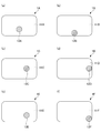
- 5 (a) to 5 (f) are cross-sectional views showing various modified examples of the resin-coated superconducting wire (flat shape), respectively.
- FIG. 6 is a cross-sectional view of a conventional resin-coated superconducting wire.
- the present inventors have a resin-coated superconducting wire having a matrix resin made of a synthetic resin material and a superconducting wire extending in the matrix resin, and the matrix resin is cut off when viewed in a cross section of the resin-coated superconducting wire.
- a resin-coated superconducting wire that is lighter, more flexible, and inexpensive than the conventional one by having an area larger than the cross-sectional area of the superconducting wire, and completed the present disclosure. ..
- the resin-coated superconducting wire according to the present disclosure includes a matrix resin made of a synthetic resin material and a superconducting wire extending in the matrix resin. Then, in the resin-coated superconducting wire, the cross-sectional area of the matrix resin is equal to or larger than the cross-sectional area of the superconducting wire when viewed in cross section of the resin-coated superconducting wire.
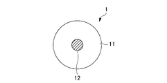
- FIG. 1 is a cross-sectional view of the resin-coated superconducting wire of one embodiment
- FIG. 2 is a cross-sectional view of the resin-coated superconducting wire of one embodiment
- the resin-coated superconducting wire 1 has a matrix resin 11 made of a synthetic resin material and a superconducting wire 12 extending in the matrix resin 11.
- the cross-sectional area of the matrix resin 11 is equal to or larger than the cross-sectional area of the superconducting wire 12 when viewed in the cross section of the resin-coated superconducting wire 1.
- FIG. 1 is a resin-coated superconducting wire 1 having a flat cross-sectional shape
- the resin-coated superconducting wire 1 shown in FIGS. 1 and 2 is a single-layer coated wire in which a matrix resin 11 composed of a single-layer matrix resin layer covers the outer periphery of the superconducting wire 12.
- the current flowing inside the superconducting wire 12 constituting the resin-coated superconducting wire 1 is relatively small. Therefore, the superconducting wire 12 used for such an application is less likely to cause quenching, and even if it is quenched, the current is small, so that it is not necessary to combine a large amount of stabilized copper.
- the superconducting wire 12 is extended (preferably embedded) in the matrix resin 11 having the same or larger cross-sectional area in cross section. As a result, in the resin-coated superconducting wire, the matrix resin 11 acts as a so-called spacer, and the adjacent superconducting wires 12, 12 can be arranged at a certain distance from each other.
- the matrix resin 11 is made of a synthetic resin material.
- the matrix resin 11 ensures the insulation between the superconducting wires 12 and also serves as a so-called spacer as described above, and arranges the adjacent superconducting wires 12 at a certain distance from each other.
- the matrix resin is solid and excludes braided yarns.
- the matrix resin 11 is extruded, which is an effective method for performing thick-wall coating molding so that the cross-sectional area of the matrix resin 11 is equal to or larger than the cross-sectional area of the superconducting wire 12 when viewed from the cross section of the resin-coated superconducting wire 1.
- a thermoplastic resin that can be molded is preferable, and a polyamide or polyolefin is more preferable.
- the polyamide is preferably nylon.
- the above thermoplastic resins include, for example, polyethylene, polypropylene, polystyrene, nylon 11, nylon 12, nylon 6, nylon 66, nylon 610, nylon MXD6 (polycondensate of metaxylylene diamine and adipic acid), polyethylene terephthalate, and poly.
- Butylene terephthalate, polyethylene naphthalate, polyphenylene sulfide, ethylene tetrafluoride / propylene hexafluoride copolymer resin (FEP), ethylene tetrafluoride / ethylene copolymer resin (ETFE), polycarbonate, polyphenylene ether, polyetherimide, polyether Polyethylene and the like are preferable, and these resins may be a single substance or a mixture of two or more kinds of resins.
- the synthetic resin material constituting the matrix resin 11 includes not only a synthetic resin but also a resin composition mainly composed of a synthetic resin.
- the resin composition may contain various additives contained in ordinary resin compositions, such as additives that improve mechanical or chemical durability, such as various fillers and antioxidants.
- additives that improve mechanical or chemical durability such as various fillers and antioxidants.
- the heat shrinkage rate of the matrix resin 11 can be made smaller and closer to the heat shrinkage rate of the superconducting wire 12, and the heat cycle property of the resin-coated superconducting wire 1 can be improved. Can be done.
- the melting point of the matrix resin 11 is preferably, for example, 290 ° C. or lower, more preferably 280 ° C. or lower, and further preferably 270 ° C. or lower.
- the above crystalline resins constituting the matrix resin 11 include, for example, polyethylene, polypropylene, nylon 11, nylon 12, nylon 6, nylon 66, nylon 610, nylon MXD6, polyethylene terephthalate, polybutylene terephthalate, polyethylene naphthalate, and polyphenylene sulfide.
- Polyethylene tetrafluoride / propylene hexafluoride copolymer resin (FEP), ethylene tetrafluoride / ethylene copolymer resin (ETFE) and the like are suitable.
- the melting point of the matrix resin 11 is preferably 210 ° C. or lower, more preferably 200 ° C. or lower, and 190 ° C. The following is more preferable.
- the above-mentioned crystalline resins constituting the matrix resin 11 polyethylene, polypropylene, nylon 11, and nylon 12 are preferable.
- the matrix resin 11 is preferably nylon or polyolefin, and among them, nylon 11, nylon 12, nylon 6, nylon 66, nylon 610, nylon MXD6, polyethylene, and polypropylene are more preferable, and particularly low melting point and low heat shrinkage. Nylon 11, nylon 12, polyethylene, and polypropylene are more preferable because of their rate, excellent water absorption resistance (low water absorption rate), flexibility, and mechanical properties.
- the glass transition point of the synthetic resin material constituting the matrix resin 11 is preferably, for example, 250 ° C. or lower, more preferably 240 ° C. or lower, 230 ° C. or lower. It is more preferably ° C. or lower.
- the glass transition point of the synthetic resin material constituting the matrix resin 11 is preferably, for example, 250 ° C. or lower, more preferably 240 ° C. or lower, 230 ° C. or lower. It is more preferably ° C. or lower.
- amorphous resin constituting the matrix resin 11 for example, polycarbonate, polyphenylene ether, polyetherimide, polyether sulfone and the like are suitable.
- FIG. 3 is a cross-sectional view of another example of the resin-coated superconducting wire (flat shape), and FIG. 4 is a cross-sectional view of another example of the resin-coated superconducting wire (circular shape).
- the resin-coated superconducting wire 1 shown in FIGS. 3 to 4 is a multilayer coated wire in which a matrix resin 11 composed of a multilayer resin layer covers the outer periphery of the superconducting wire 12.
- the matrix resin 11 is an annular inner matrix resin layer 11a that covers the outer periphery of the superconducting wire 12 and one that covers the inner matrix resin layer 11a from the outside. It is composed of the above outer matrix resin layer 11b.
- FIGS. 3 to 4 show a two-layer structure in which the matrix resin 11 is composed of an inner matrix resin layer 11a and one outer matrix resin layer 11b.
- the resin-coated superconducting wire 1 is preferably a multilayer-coated wire having two or more matrix resin layers, such as the inner matrix resin layer 11a and the outer matrix resin layer 11b. It is more preferable that the resin layer is a multilayer coated wire having 2 or more and 4 or less layers.
- the resin-coated superconducting wire 1 a multilayer-coated wire, it can be expected that the dimensional accuracy of the extrusion-coated wire can be improved by reducing the amount of resin at the time of one-time extrusion coating. Further, by using a different resin for each matrix resin layer, the functionality of the resin-coated superconducting wire 1 can be further enhanced.
- the inner matrix resin layer 11a which is the first layer on the conductor side, has an epoxy group, an oxazolyl group, an amino group and a maleic anhydride residue.
- an olefin resin containing at least one functional group selected from the group consisting of groups, or a multilayer coated wire which is a copolymer thereof (also referred to as a copolymer (A)) the superconducting wire 12 and Adhesion with the outer polyolefin resin 11b can be improved.
- the adhesion is improved in the same manner as described above by forming the inner matrix resin layer 11a into a multilayer coated wire which is an olefin-based copolymer (also referred to as an olefin-based copolymer (B)) containing a metal salt of a carboxylic acid. Can be expected.
- an olefin-based copolymer also referred to as an olefin-based copolymer (B)
- B olefin-based copolymer
- the olefin components constituting the copolymer (A) include ethylene, propylene, butene-1, pentene-1,4-methylpentene-1, isobutylene, hexene-1, decene-1, octene-1, 1,4. -Hexadiene, dicyclopentadiene and the like are preferable, and among them, ethylene, propylene and butene-1 are preferable. Further, these components may be used alone or in combination of two or more.
- the copolymer component other than the olefin constituting the copolymer (A) may be at least one of an acrylic component and a vinyl component.
- Acrylic acid components include acrylic acid, methyl acrylate, ethyl acrylate, n-propyl acrylate, isopropyl acrylate, n-butyl acrylate, t-butyl acrylate, isobutyl acrylate, methyl methacrylate, ethyl methacrylate, Butyl methacrylate and the like are suitable.
- vinyl component vinyl acetate, vinyl propionate, vinyl butyrate, vinyl chloride, vinyl alcohol, styrene and the like are suitable. Of these, methyl acrylate and methyl methacrylate are more preferable. Further, these components may be used alone or in combination of two or more.
- Typical preferred examples of the copolymer (A) include polyethylene or polypropylene grafted with maleic anhydride, an ethylene / glycidyl methacrylate copolymer, and the like, and examples of the city plate resin include Admer ( There are Mitsui Chemical Co., Ltd., product name), Bond First (Sumitomo Chemical Industry Co., Ltd., product name), and Rotada (Atofina Co., Ltd., product name).
- the carboxylic acid constituting the olefin copolymer (B) is preferably an unsaturated monocarboxylic acid such as acrylic acid, methacrylic acid or crotonic acid, or a non-carboxylic acid such as maleic acid, fumaric acid or phthalic acid.
- unsaturated monocarboxylic acids such as acrylic acid, methacrylic acid or crotonic acid
- non-carboxylic acid such as maleic acid, fumaric acid or phthalic acid.
- Saturated dicarboxylic acids can be mentioned, and examples of these metal salts include salts of Zn, Na, K, Mg and the like.
- an olefin-based copolymer (B) preferably, a part of the carboxylic acid of the ethylene-methacrylic acid copolymer is made into a metal salt, and a resin generally called an ionomer (for example, Hymilan; trade name, Mitsui) (Made by Polychemical Co., Ltd.) can be mentioned.
- an ionomer for example, Hymilan; trade name, Mitsui
- the heat shrinkage rate calculated by the following method is preferably 5% or less, more preferably 2% or less, and further preferably 1% or less.
- Heat shrinkage rate (%) ⁇ (Dimensions of resin-coated superconducting wire before immersion-Dimensions of resin-coated superconducting wire after immersion) / Dimensions of resin-coated superconducting wire before immersion ⁇ ⁇ 100 ⁇ ⁇ ⁇ Equation (1)
- the water absorption rate calculated by the following method is more preferably 1.0% or less, and further preferably 0.7% or less.
- the lower the water absorption rate the smaller the expansion of the surface of the matrix resin 11. Therefore, it is possible to suppress damage or deterioration of the matrix resin 11 due to water absorption, deterioration of the matrix resin 11 due to water absorption, or deterioration of mechanical strength due to generation of cracks.
- the calculation method shown below is one of the methods for obtaining the water absorption rate of plastic specified in JIS K7209.
- the superconducting wire 12 is a wire rod extending in the matrix resin 11 described above, and has superconducting property.
- the size of the cross section of the superconducting wire 12 is preferably 0.05 to 2.00 mm ⁇ , more preferably 0.07 to 1.50 mm ⁇ , and 0.1 to 1 for a circular shape, for example. If the cross section of the superconducting wire 12 is a flat shape, the long side thereof is preferably 0.8 mm to 2.5 mm, more preferably 1.5 mm to 2.0 mm. The short side is preferably 0.5 mm to 1.5 mm, and more preferably 0.9 mm to 1.2 mm.
- the superconducting wire 12 is composed of one or more superconducting materials selected from the group consisting of, for example, metal / niobium titanium, metal / niobium tritin, metal / magnesium diboride, rare earth-based and bismuth-based superconducting materials. Is preferable.
- metal / niobium titanium metal / niobium tritin
- metal / magnesium diboride rare earth-based and bismuth-based superconducting materials.
- metal / niobium titanium metal / niobium tritin
- metal / magnesium diboride means that a metal such as copper or iron is coated around niobium titanium, niobium tritin or magnesium diboride. It is a composite.
- rare earth material examples include YBa 2 Cu 3 O 7- ⁇ and GdBa 2 Cu 3 O 7- ⁇ .
- bismuth-based material examples include Bi 2 Sr 2 Ca 2 Cu 3 O 10 + ⁇ and Bi 2 Sr 2 CaCu 2 O 8 + ⁇ .
- the superconducting wire 12 either a single wire or a stranded wire obtained by twisting a plurality of strands can be used.
- the cross-sectional area of the matrix resin 11 is equal to or larger than the cross-sectional area of the superconducting wire 12 when viewed in cross section.
- the ratio of the cross-sectional area of the matrix resin 11 to the cross-sectional area of the superconducting wire 12 is doubled. It is preferably 5 times or more, more preferably 5 times or more, further preferably 10 times or more, particularly preferably 20 times or more, and most preferably 40 times or more.
- the upper limit of the cross-sectional area ratio is preferably 1000 times, for example, from the practical viewpoints such as suitability as a coil material and handleability of winding work.
- the superconducting wire 12 is located at the center (center of gravity) of the matrix resin 11 in FIGS. 1 and 2, but the resin-coated superconducting wire 12 is shown. As long as it is not exposed from the surface of the wire 1 (as long as even a small amount of the resin component of the matrix resin 11 is present on the surface of the resin-coated superconducting wire), it may be present at any position in the matrix resin 11. For example, FIGS.
- 5A to 5F show cross sections of resin-coated superconducting wires 1A to 1F having a flat cross-sectional shape, in which superconducting wires 12A to 12F are arranged at different cross-sectional positions of the matrix resins 11A to 11F, respectively.
- This is a modified example of.
- one superconducting wire 12 is arranged as a single wire or a stranded wire with respect to one matrix resin 11.
- the resin-coated superconducting wire may have any shape such as a circular shape including an elliptical shape, a triangular shape, a square shape, and a flat shape, but the resin-coated superconducting wire should have a flat shape due to the ease of coil formation. Is preferable.
- the cross-sectional shape of the resin-coated superconducting wire is a flat shape
- the cross-sectional shape of the resin-coated superconducting wire includes those having an R value of 1 mm or less at the corners.
- the long side of the cross section of the resin-coated superconducting wire is preferably, for example, 0.5 mm to 10 mm, and more preferably 1 mm to 7 mm.
- the short side of the cross section of the resin-coated superconducting wire is preferably, for example, 0.1 mm to 5 mm, and more preferably 0.5 mm to 3 mm.
- the dimensional accuracy of the width and thickness of the resin-coated superconducting wire is preferably ⁇ 0.10 mm or less, and preferably ⁇ 0.05 mm or less.
- the "dimensional accuracy” refers to the range of the difference between the maximum value and the minimum value of the dimensions of one resin-coated superconducting wire.
- the resin-coated superconducting wire can realize higher electromagnetic shielding performance.
- a method of scraping the outer surface after resin extrusion processing can be mentioned.
- a method of coating the surface of the above-mentioned matrix resin with, for example, a UV curable resin material can also be mentioned.
- the resin-coated superconducting wire as described above can be applied to a superconducting coil, particularly a shield coil used in an NMR device, an MRI inspection device, or the like.
- the voltage that can be applied to the resin-coated superconducting wire as described above is not particularly limited, but is, for example, preferably 0 to 50 V, more preferably 0 to 20 V, and even more preferably 0 to 10 V. ..
- the resin-coated superconducting wire is lighter and cheaper than the conventional superconducting wire provided with stabilized copper, and further, it is less prone to bending habits, has improved flexibility, and has flexibility such as flexibility. It is also excellent in handling, so it is easy to wind when coiling.
- the resin-coated superconducting wire according to the above embodiment is, for example, a method for manufacturing an extruded body of a normal resin material by inserting the superconducting wire into a synthetic resin raw material constituting a matrix resin. Similarly, it can be manufactured by extrusion molding. The heating temperature, extrusion speed, and the like may be appropriately adjusted depending on the type of synthetic resin raw material, the size and shape of the molded product to be molded, and the like.
- a superconducting wire which is a wire
- resin in advance and then embedded in a copper channel in a two-step process.
- the resin-coated superconducting wire of the embodiment since the matrix resin can form the same shape as the copper channel, the conventional two-step process can be completed in one step.
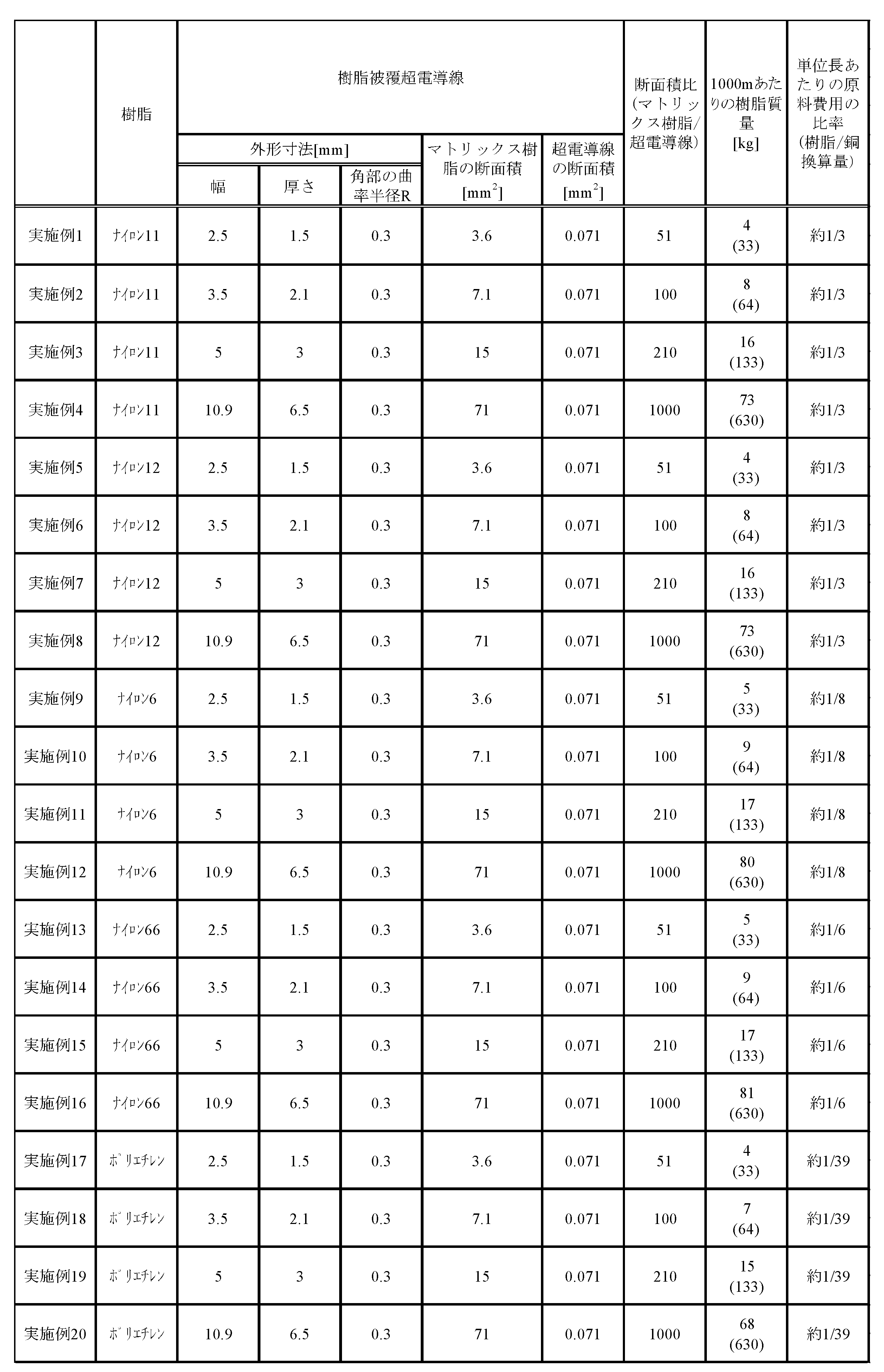
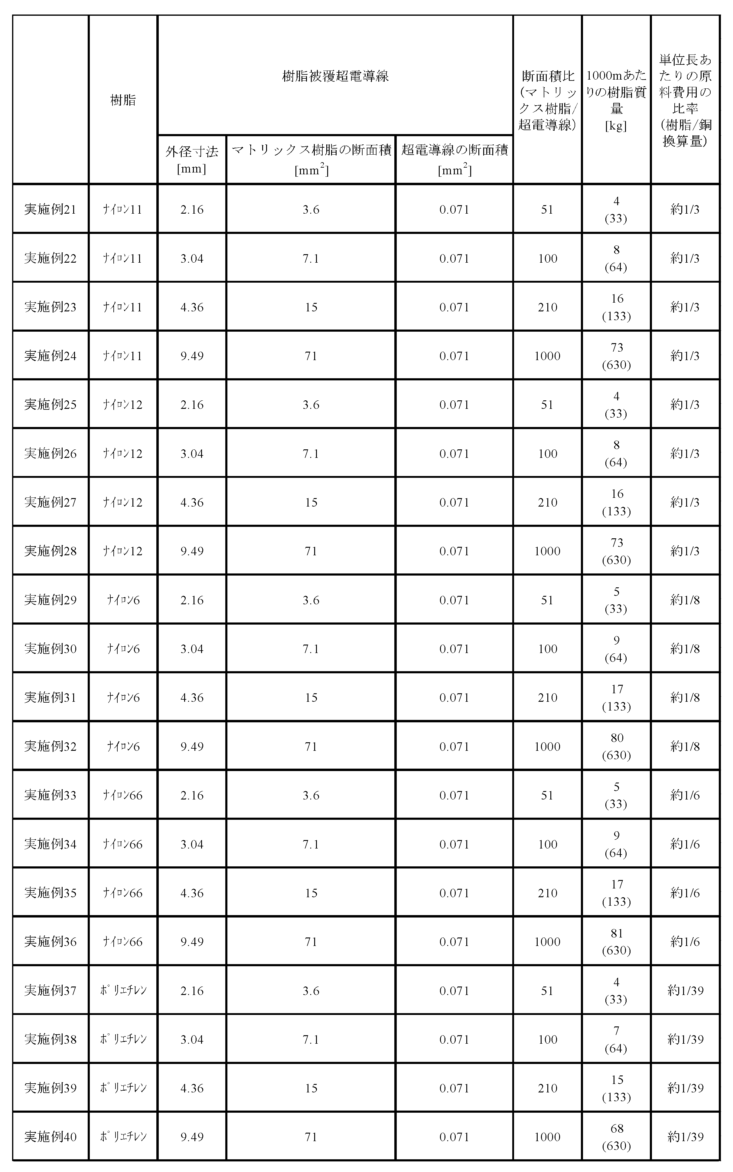
- Nylon 11 (ARKEMA, BESN Noir TL), Nylon 12 (Ube Kosan, UBESTA3030LUX), Nylon 6 (Ube Kosan, UBESTA1024JI), Nylon 66 (Asahi Kasei, Leona (registered trademark) 1300S) as raw materials for synthetic resin materials , High-density polyethylene (Asahi Kasei, Suntech (registered trademark) -HD B891) was used, and a 0.3 mm ⁇ copper / nylon superconducting wire was inserted into the raw material of the synthetic resin material to form a flat shape (Examples 1 to 20).
- Examples 21 to 40 Or round shape (Examples 21 to 40) and extruded under temperature conditions of melting point + 20 ° C or higher and melting point + 80 ° C or lower of each resin material using a mold having the dimensions shown in Tables 2 and 3 below. ..
- the superconducting wire was arranged so as to be the center of the synthetic resin material.
- resin-coated superconducting wires having a flat cross-sectional shape were manufactured.
- Examples 21 to 40 resin-coated superconducting wires having a circular cross-sectional shape were manufactured.
- High-density polyethylene (Asahi Kasei, Suntech (registered trademark) -HD B891) is used as a raw material for synthetic resin materials, and modified low-density polyethylene (Mitsui Chemicals, Admer NB508) graft-copolymerized with maleic anhydride is 20 ⁇ m thick.
- Insert the 0.3 mm ⁇ copper / niobium titanium superconducting wire coated with the above into the raw material of the synthetic resin material and use a mold that is flat and has the dimensions shown in Table 4 below, and the melting point of each resin material is +20. Extrusion was performed under temperature conditions of ° C. or higher and melting point + 80 ° C. or lower. As shown in FIG. 3, the superconducting wire was arranged so as to be the center of the synthetic resin material.
- Example 42 Example 41 except that a 0.3 mm ⁇ copper / niobium-titanium superconducting wire coated with an ethylene-methacrylic acid copolymer (manufactured by Mitsui Polychemical Co., Ltd., Hymilan 1855) in which a part of the carboxylic acid is a metal salt and coated with a thickness of 20 ⁇ m was used.
- a resin-coated superconducting wire was obtained in the same manner as above.
- High-density polyethylene (Asahi Kasei, Suntech (registered trademark) -HD B891) is used as a raw material for synthetic resin materials, and modified low-density polyethylene (Mitsui Chemicals, Admer NB508) graft-copolymerized with maleic anhydride is 20 ⁇ m thick.
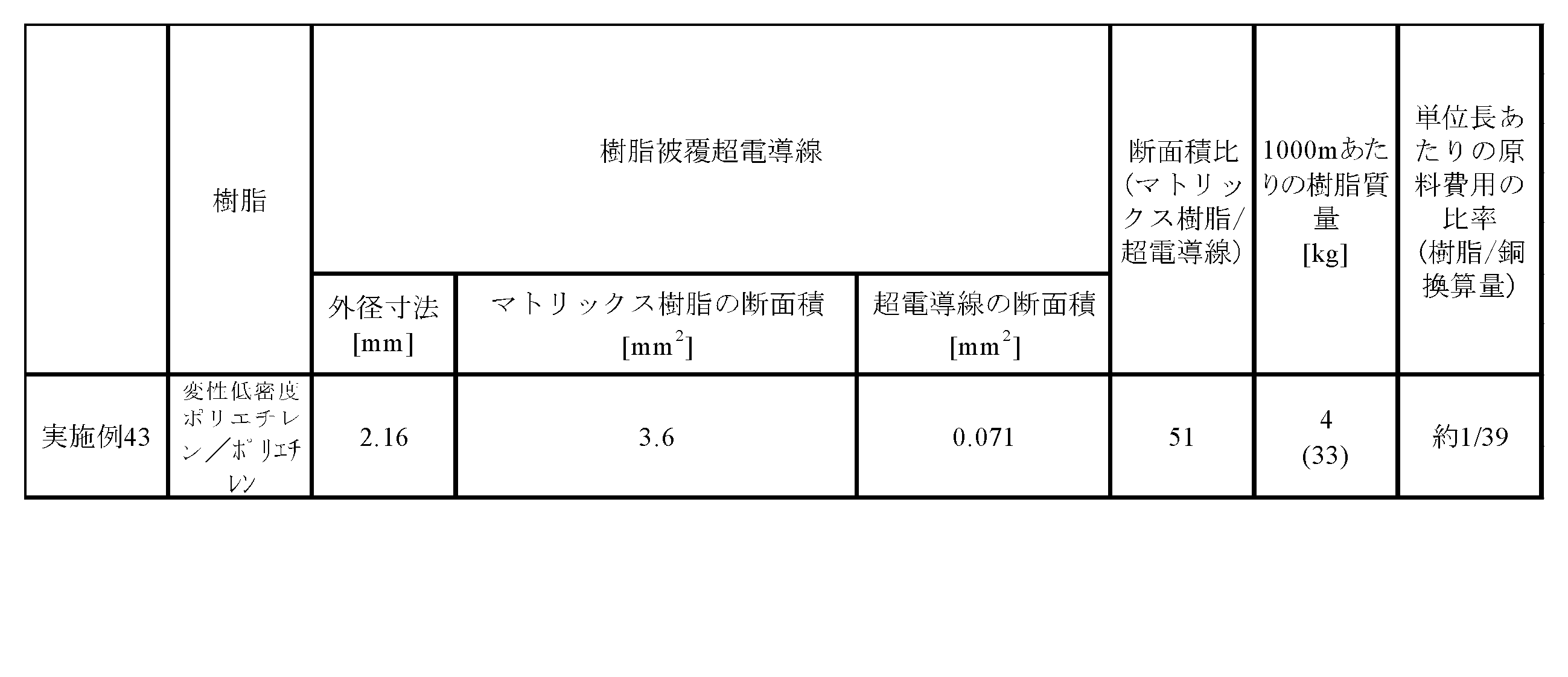
- the cross-sectional area of the matrix resin was calculated from the cross-sectional area of the resin-coated superconducting wire, the outer cross-sectional area of the resin-coated superconducting wire, and the difference between the cross-sectional area and the superconducting wire. From the cross-sectional area of this matrix resin, the mass and cost of the resin per 1000 m in length of the resin-coated superconducting wire, and their copper equivalent values were calculated. The results are shown in Tables 2 to 5 below. In Tables 2 to 5, the amount in parentheses indicates the amount of copper converted in the same volume.
- Table 1 shows the melting point, glass transition point, heat shrinkage rate, and water absorption rate of each of the synthetic resin materials used in Examples 1 to 43.
- the heat shrinkage rate and the water absorption rate were determined by the above-mentioned method.
- the resin-coated superconducting wires of Examples 1 to 43 were obtained with the same dimensions as the superconducting wire using the conventional copper channel, and thereby achieved the same magnetic shielding characteristics as the superconducting wire using the conventional copper channel. It was confirmed that it could be done.
Landscapes
- Physics & Mathematics (AREA)
- Spectroscopy & Molecular Physics (AREA)
- Engineering & Computer Science (AREA)
- Power Engineering (AREA)
- Chemical & Material Sciences (AREA)
- Chemical Kinetics & Catalysis (AREA)
- Superconductors And Manufacturing Methods Therefor (AREA)
- Magnetic Resonance Imaging Apparatus (AREA)
Abstract
Description
[2] 前記超電導線が、金属/ニオブチタン、金属/ニオブ三スズ、金属/二ホウ化マグネシウム、希土類系およびビスマス系の超電導材料からなる群から選択される1種以上からなることを特徴とする、上記[1]に記載の樹脂被覆超電導線。
[3] 前記合成樹脂材料が、熱可塑性樹脂であることを特徴とする、上記[1]または[2]に記載の樹脂被覆超電導線。
[4] 前記熱可塑性樹脂の融点が290℃以下であることを特徴とする、上記[3]に記載の樹脂被覆超電導線。
[5] 前記熱可塑性樹脂の融点が210℃以下であることを特徴とする、上記[3]または[4]に記載の樹脂被覆超電導線。
[6] 前記合成樹脂材料が、ポリアミドまたはポリオレフィンであることを特徴とする、上記[1]~[5]のいずれか1つに記載の樹脂被覆超電導線。
[7] 前記ポリアミドがナイロンであることを特徴とする、上記[6]に記載の樹脂被覆超電導線。
[8] 前記合成樹脂材料が、ナイロン11、ナイロン12またはポリエチレンであることを特徴とする、上記[1]~[7]のいずれか1つに記載の樹脂被覆超電導線。
[9] 前記合成樹脂材料が、250℃以下のガラス転移点を有する非晶性樹脂であることを特徴とする、上記[1]~[5]のいずれか1つに記載の樹脂被覆超電導線。
[10] 前記樹脂被覆超電導線は、前記マトリックス樹脂が前記超電導線の外周を覆う内側マトリックス樹脂層と前記内側マトリックス樹脂層の外側を覆う1つ以上の外側マトリックス樹脂層とから構成される2層以上のマトリックス樹脂層から構成される、多層被覆線であることを特徴とする、上記[1]~[9]のいずれか1つに記載の樹脂被覆超電導線。
[11] 前記内側マトリックス樹脂層は、エポキシ基、オキサゾリル基、アミノ基及び無水マレイン酸残基からなる群から選択される少なくとも1種類の官能基を含有するオレフィン系樹脂、又その共重合体であることを特徴とする、上記[10]に記載の樹脂被覆超電導線。
[12] 前記内側マトリックス樹脂層は、カルボン酸の金属塩を含有するオレフィン系共重合体であることを特徴とする、上記[10]に記載の樹脂被覆超電導線。
[13] 前記超電導線が単線であることを特徴とする、上記[1]~[12]のいずれか1つに記載の樹脂被覆超電導線。
[14] 前記超電導線が撚線であることを特徴とする、上記[1]~[12]のいずれか1つに記載の樹脂被覆超電導線。
[15] 前記樹脂被覆超電導線の横断面形状が、平角形状であることを特徴とする、上記[1]~[14]のいずれか1つに記載の樹脂被覆超電導線。
[16] 前記樹脂被覆超電導線の横断面形状が、円形状であることを特徴とする、上記[1]~[14]のいずれか1つに記載の樹脂被覆超電導線。
[17] 前記樹脂被覆超電導線の幅および厚さの寸法精度が±0.10mm以下であることを特徴とする、上記[1]~[16]のいずれか1つに記載の樹脂被覆超電導線。
[18] 前記樹脂被覆超電導線の幅および厚さの寸法精度が±0.05mm以下であることを特徴とする、上記[1]~[17]のいずれか1つに記載の樹脂被覆超電導線。
[19] 上記[1]~[18]のいずれか1つに記載の樹脂被覆超電導線を用いた超電導コイル。
[20] 上記[1]~[18]のいずれか1つに記載の樹脂被覆超電導線を用いたシールドコイル。
本開示に係る樹脂被覆超電導線は、合成樹脂材料からなるマトリックス樹脂と、マトリックス樹脂中に延在する超電導線とを有する。そして、樹脂被覆超電導線において、樹脂被覆超電導線の横断面で見て、マトリックス樹脂の断面積が、超電導線の断面積以上である。
マトリックス樹脂11は、合成樹脂材料からなるものである。マトリックス樹脂11は、超電導線12間の絶縁性を担保するとともに、上述したとおりいわゆるスペーサーの役割を果たし、隣接する超電導線12同士を、一定の距離を隔てて配置するものである。なお、マトリックス樹脂は、固形状であり、糸を編組したものを除くものとする。
樹脂被覆超電導線1の長手方向に切り出した0.2gの樹脂被覆超電導線1を、500mL、液体ヘリウムに数分間浸漬して、樹脂被覆超電導線1の寸法を測定し、以下の式(1)により、熱収縮率を算出する。
熱収縮率(%)={(浸漬前の樹脂被覆超電導線の寸法-浸漬後の樹脂被覆超電導線の寸法)/浸漬前の樹脂被覆超電導線の寸法}×100 ・・・式(1)
樹脂被覆超電導線1の長手方向に切り出した1.0gの樹脂被覆超電導線1を、500mL、23℃の水に24時間浸漬した後、表面の水を拭き取り、樹脂被覆超電導線1の質量を測定し、以下の式(2)により吸水率を算出する。
吸水率(%)={(浸漬前の樹脂被覆超電導線の質量-浸漬後の樹脂被覆超電導線の質量)/浸漬前の樹脂被覆超電導線の質量}×100 ・・・式(2)
超電導線12は、上述したマトリックス樹脂11中に延在する線材であり、超電導性を有するものである。
上述したとおり、樹脂被覆超電導線1においては、その横断面で見て、マトリックス樹脂11の断面積は、超電導線12の断面積以上である。
以上のような実施形態の樹脂被覆超電導線は、例えば、マトリックス樹脂を構成する合成樹脂原料中に超電導線を挿入して、通常の樹脂材料の押出成形体の製造方法と同様に、押出成形することにより製造することができる。加熱温度や押出速度などは、合成樹脂原料の種類、成形する成形体の大きさや形状などにより、適宜調整すればよい。
合成樹脂材料の原料としてナイロン11(ARKEMA製、BESN Noir TL)、ナイロン12(宇部興産製、UBESTA3030LUX)、ナイロン6(宇部興産製、UBESTA1024JI)、ナイロン66(旭化成製、レオナ(登録商標)1300S)、高密度ポリエチレン(旭化成製、サンテック(登録商標)-HD B891)を用い、0.3mmφの銅/ニオブチタン超電導線を、合成樹脂材料の原料中に挿入して、平角状(実施例1~20)または丸状(実施例21~40)でかつ下記表2と3に示す寸法となるような金型を用い、各樹脂材料の融点+20℃以上融点+80℃以下の温度条件下で押出加工した。なお、超電導線の配置は、図1と図2に示すように、合成樹脂材料の中心となるように配置した。実施例1~20では、横断面形状が平角形状である樹脂被覆超電導線を製造した。実施例21~40では、横断面形状が円形状である樹脂被覆超電導線を製造した。
合成樹脂材料の原料として高密度ポリエチレン(旭化成製、サンテック(登録商標)-HD B891)を用い、無水マレイン酸をグラフト共重合させた変性低密度ポリエチレン(三井化学製、アドマーNB508)を厚さ20μmで被覆した0.3mmφの銅/ニオブチタン超電導線を、合成樹脂材料の原料中に挿入して、平角状でかつ下記表4に示す寸法となるような金型を用い、各樹脂材料の融点+20℃以上融点+80℃以下の温度条件下で押出加工した。なお、超電導線の配置は、図3に示すように、合成樹脂材料の中心となるように配置した。
カルボン酸の一部を金属塩にしたエチレン-メタクリル酸共重合体(三井ポリケミカル製、ハイミラン1855)を厚さ20μmで被覆した0.3mmφの銅/ニオブチタン超電導線を使用した以外は実施例41と同様にして樹脂被覆超電導線を得た。
合成樹脂材料の原料として高密度ポリエチレン(旭化成製、サンテック(登録商標)-HD B891)を用い、無水マレイン酸をグラフト共重合させた変性低密度ポリエチレン(三井化学製、アドマーNB508)を厚さ20μmで被覆した0.3mmφの銅/ニオブチタン超電導線を、合成樹脂材料の原料中に挿入して、丸状でかつ下記表5に示す寸法となるような金型を用い、各樹脂材料の融点+20℃以上融点+80℃以下の温度条件下で押出加工した。なお、超電導線の配置は、図4に示すように、合成樹脂材料の中心となるように配置した。


11,11A,11B,11C,11D,11E,11F マトリックス樹脂
11a 内側マトリックス樹脂層
11b 外側マトリックス樹脂層
12,12A,12B,12C,12D,12E,12F,22 超電導線
21 安定化銅
Claims (20)
- 合成樹脂材料からなるマトリックス樹脂と、
前記マトリックス樹脂中に延在する超電導線と
を有する樹脂被覆超電導線であって、
前記樹脂被覆超電導線の横断面で見て、前記マトリックス樹脂の断面積が、前記超電導線の断面積以上であることを特徴とする、樹脂被覆超電導線。 - 前記超電導線が、金属/ニオブチタン、金属/ニオブ三スズ、金属/二ホウ化マグネシウム、希土類系およびビスマス系の超電導材料からなる群から選択される1種以上からなることを特徴とする、請求項1に記載の樹脂被覆超電導線。
- 前記合成樹脂材料が、熱可塑性樹脂であることを特徴とする、請求項1または2に記載の樹脂被覆超電導線。
- 前記熱可塑性樹脂の融点が290℃以下であることを特徴とする、請求項3に記載の樹脂被覆超電導線。
- 前記熱可塑性樹脂の融点が210℃以下であることを特徴とする、請求項3または4に記載の樹脂被覆超電導線。
- 前記合成樹脂材料が、ポリアミドまたはポリオレフィンであることを特徴とする、請求項1~5のいずれか1項に記載の樹脂被覆超電導線。
- 前記ポリアミドがナイロンであることを特徴とする、請求項6に記載の樹脂被覆超電導線。
- 前記合成樹脂材料が、ナイロン11、ナイロン12またはポリエチレンであることを特徴とする、請求項1~7のいずれか1項に記載の樹脂被覆超電導線。
- 前記合成樹脂材料が、250℃以下のガラス転移点を有する非晶性樹脂であることを特徴とする、請求項1~5のいずれか1項に記載の樹脂被覆超電導線。
- 前記樹脂被覆超電導線は、前記マトリックス樹脂が前記超電導線の外周を覆う内側マトリックス樹脂層と前記内側マトリックス樹脂層の外側を覆う1つ以上の外側マトリックス樹脂層とから構成される2層以上のマトリックス樹脂層から構成される、多層被覆線であることを特徴とする、請求項1~9のいずれか1項に記載の樹脂被覆超電導線。
- 前記内側マトリックス樹脂層は、エポキシ基、オキサゾリル基、アミノ基及び無水マレイン酸残基からなる群から選択される少なくとも1種類の官能基を含有するオレフィン系樹脂、又その共重合体であることを特徴とする、請求項10に記載の樹脂被覆超電導線。
- 前記内側マトリックス樹脂層は、カルボン酸の金属塩を含有するオレフィン系共重合体であることを特徴とする、請求項10に記載の樹脂被覆超電導線。
- 前記超電導線が単線であることを特徴とする、請求項1~12のいずれか1項に記載の樹脂被覆超電導線。
- 前記超電導線が撚線であることを特徴とする、請求項1~12のいずれか1項に記載の樹脂被覆超電導線。
- 前記樹脂被覆超電導線の横断面形状が、平角形状であることを特徴とする、請求項1~14のいずれか1項に記載の樹脂被覆超電導線。
- 前記樹脂被覆超電導線の横断面形状が、円形状であることを特徴とする、請求項1~14のいずれか1項に記載の樹脂被覆超電導線。
- 前記樹脂被覆超電導線の幅および厚さの寸法精度が±0.10mm以下であることを特徴とする、請求項1~16のいずれか1項に記載の樹脂被覆超電導線。
- 前記樹脂被覆超電導線の幅および厚さの寸法精度が±0.05mm以下であることを特徴とする、請求項1~17のいずれか1項に記載の樹脂被覆超電導線。
- 請求項1~18のいずれか1項に記載の樹脂被覆超電導線を用いた超電導コイル。
- 請求項1~18のいずれか1項に記載の樹脂被覆超電導線を用いたシールドコイル。
Priority Applications (6)
| Application Number | Priority Date | Filing Date | Title |
|---|---|---|---|
| JP2021521919A JP7704676B2 (ja) | 2019-05-31 | 2020-05-29 | 樹脂被覆超電導線、超電導コイルおよびシールドコイル |
| CN202080040169.3A CN113950725B (zh) | 2019-05-31 | 2020-05-29 | 树脂被覆超导线、超导线圈及屏蔽线圈 |
| KR1020217039966A KR102847529B1 (ko) | 2019-05-31 | 2020-05-29 | 수지 피복 초전도선, 초전도 코일 및 실드 코일 |
| EP20815589.5A EP3979264A4 (en) | 2019-05-31 | 2020-05-29 | Resin-coated superconducting wire, superconducting coil, and shield coil |
| US17/615,236 US20220230777A1 (en) | 2019-05-31 | 2020-05-29 | Resin coated superconducting wire, superconducting coil, and shield coil |
| JP2025033274A JP2025078729A (ja) | 2019-05-31 | 2025-03-03 | 樹脂被覆超電導線、超電導コイルおよびシールドコイル |
Applications Claiming Priority (2)
| Application Number | Priority Date | Filing Date | Title |
|---|---|---|---|
| JP2019103286 | 2019-05-31 | ||
| JP2019-103286 | 2019-05-31 |
Publications (1)
| Publication Number | Publication Date |
|---|---|
| WO2020241893A1 true WO2020241893A1 (ja) | 2020-12-03 |
Family
ID=73552838
Family Applications (1)
| Application Number | Title | Priority Date | Filing Date |
|---|---|---|---|
| PCT/JP2020/021496 Ceased WO2020241893A1 (ja) | 2019-05-31 | 2020-05-29 | 樹脂被覆超電導線、超電導コイルおよびシールドコイル |
Country Status (6)
| Country | Link |
|---|---|
| US (1) | US20220230777A1 (ja) |
| EP (1) | EP3979264A4 (ja) |
| JP (2) | JP7704676B2 (ja) |
| KR (1) | KR102847529B1 (ja) |
| CN (1) | CN113950725B (ja) |
| WO (1) | WO2020241893A1 (ja) |
Citations (2)
| Publication number | Priority date | Publication date | Assignee | Title |
|---|---|---|---|---|
| JPS5229071U (ja) * | 1975-08-20 | 1977-03-01 | ||
| JP2013020727A (ja) * | 2011-07-07 | 2013-01-31 | Nitto Denko Corp | 平角電線用被覆材、被覆平角電線及び電気機器 |
Family Cites Families (20)
| Publication number | Priority date | Publication date | Assignee | Title |
|---|---|---|---|---|
| US3310398A (en) * | 1964-08-14 | 1967-03-21 | Nat Res Corp | Electrical materials and devices |
| US3527873A (en) * | 1968-12-27 | 1970-09-08 | Atomic Energy Commission | Composite superconducting cable having a porous matrix |
| US3743986A (en) * | 1972-02-08 | 1973-07-03 | Atomic Energy Commission | Improved resistive envelope for a multifilament superconductor wire |
| JPS49105885U (ja) * | 1972-12-29 | 1974-09-11 | ||
| JPS50114772U (ja) * | 1974-02-27 | 1975-09-18 | ||
| JPS56137605A (en) * | 1980-03-31 | 1981-10-27 | Toshiba Corp | Superelectroconductive coil |
| DE3048418C2 (de) * | 1980-12-22 | 1983-06-09 | Siemens AG, 1000 Berlin und 8000 München | Kabelförmiger, kryogen stabilisierter Supraleiter für hohe Ströme und Wechselfeldbelastungen |
| JPS63121215A (ja) * | 1986-11-07 | 1988-05-25 | 住友電気工業株式会社 | 超電導線及びその製造方法 |
| JPH01195616A (ja) * | 1988-01-29 | 1989-08-07 | Fujikura Ltd | 酸化物系長尺超電導材の製造方法 |
| JPH0459169U (ja) * | 1990-09-28 | 1992-05-21 | ||
| JP3451401B2 (ja) * | 1992-12-16 | 2003-09-29 | 鐘淵化学工業株式会社 | 超電導線材被覆用熱融着性積層フィルム |
| JP2776180B2 (ja) * | 1992-12-18 | 1998-07-16 | 株式会社日立製作所 | 超電導マグネット、超電導マグネットコイル及びその製造方法 |
| JPH07142282A (ja) * | 1993-11-18 | 1995-06-02 | Nitto Boseki Co Ltd | コイル巻線の固定方法及び巻芯 |
| US7009104B2 (en) * | 2000-12-27 | 2006-03-07 | Pirelli Cavi E Sistemi S.P.A. | Superconducting cable |
| US20080163474A1 (en) * | 2007-01-09 | 2008-07-10 | Seung Hong | Soldered superconductor with hard insulation |
| JP5367248B2 (ja) * | 2007-10-04 | 2013-12-11 | 古河電気工業株式会社 | 多層絶縁電線 |
| CN106062893B (zh) * | 2013-12-26 | 2018-05-04 | 古河电气工业株式会社 | 绝缘电线、线圈和电气/电子设备以及抗皮膜剥离绝缘电线的制造方法 |
| FI20145755A7 (fi) * | 2014-09-01 | 2016-03-02 | Luvata Espoo Oy | Metallikokoonpano joka käsittää suprajohteen |
| JP6133249B2 (ja) * | 2014-09-09 | 2017-05-24 | 古河電気工業株式会社 | 絶縁電線、コイルおよび電気・電子機器ならびに絶縁電線の製造方法 |
| CN206179576U (zh) * | 2016-09-30 | 2017-05-17 | 无锡友方电工股份有限公司 | 高温超导绞线 |
-
2020
- 2020-05-29 WO PCT/JP2020/021496 patent/WO2020241893A1/ja not_active Ceased
- 2020-05-29 CN CN202080040169.3A patent/CN113950725B/zh active Active
- 2020-05-29 KR KR1020217039966A patent/KR102847529B1/ko active Active
- 2020-05-29 US US17/615,236 patent/US20220230777A1/en active Pending
- 2020-05-29 EP EP20815589.5A patent/EP3979264A4/en active Pending
- 2020-05-29 JP JP2021521919A patent/JP7704676B2/ja active Active
-
2025
- 2025-03-03 JP JP2025033274A patent/JP2025078729A/ja active Pending
Patent Citations (2)
| Publication number | Priority date | Publication date | Assignee | Title |
|---|---|---|---|---|
| JPS5229071U (ja) * | 1975-08-20 | 1977-03-01 | ||
| JP2013020727A (ja) * | 2011-07-07 | 2013-01-31 | Nitto Denko Corp | 平角電線用被覆材、被覆平角電線及び電気機器 |
Non-Patent Citations (1)
| Title |
|---|
| See also references of EP3979264A4 |
Also Published As
| Publication number | Publication date |
|---|---|
| JPWO2020241893A1 (ja) | 2020-12-03 |
| EP3979264A4 (en) | 2023-05-31 |
| JP7704676B2 (ja) | 2025-07-08 |
| US20220230777A1 (en) | 2022-07-21 |
| CN113950725B (zh) | 2026-01-27 |
| KR102847529B1 (ko) | 2025-08-18 |
| KR20220008296A (ko) | 2022-01-20 |
| JP2025078729A (ja) | 2025-05-20 |
| EP3979264A1 (en) | 2022-04-06 |
| CN113950725A (zh) | 2022-01-18 |
Similar Documents
| Publication | Publication Date | Title |
|---|---|---|
| JP5345057B2 (ja) | 銅覆アルミニウムチャネル超伝導体の製造方法およびチャネル導体 | |
| US8946557B2 (en) | Multilayer insulated electric wire and transformer using the same | |
| CN101479812B (zh) | 多层绝缘电线 | |
| US7771819B2 (en) | Multilayer insulated wire and transformer made using the same | |
| CN106688058B (zh) | 包括超导体的金属组件 | |
| EP1163685A1 (en) | A cable, a method of constructing a cable, and use of a cable | |
| JP6086323B2 (ja) | シールドパイプ | |
| US20140024534A1 (en) | Superconducting joints | |
| CN1358317A (zh) | 多层绝缘导线以及使用其的变压器 | |
| JP2025066827A (ja) | 超電導コイルおよびその製造方法ならびに超電導コイル用超電導平角線材 | |
| JP7704676B2 (ja) | 樹脂被覆超電導線、超電導コイルおよびシールドコイル | |
| JP7210411B2 (ja) | 超電導コイル装置 | |
| US20120103658A1 (en) | Coaxial cable center conductor having multiple precoat layers | |
| US20110203829A1 (en) | Superconducting cable with wide-width type superconducting strip lines | |
| CN105185441A (zh) | 一种船用水密电缆及其制备方法 | |
| ES2335197T3 (es) | Funda de blindaje electromagnetico, con diametro extensible. | |
| JP6887967B2 (ja) | 絶縁電線、その製造方法、コイル、電気・電子機器および電気・電子機器の製造方法 | |
| JP2008257924A (ja) | 絶縁電線及びそれを用いた変圧器 | |
| JP2008282584A (ja) | 超電導テープおよびその製造方法 | |
| JP2006114342A (ja) | 超電導ケーブル | |
| CN105869699A (zh) | 一种绝缘架空电缆 | |
| CN223038654U (zh) | 一种具有耐腐蚀效果的编织膜包线 | |
| JPWO2020067335A1 (ja) | 酸化物超電導コイルおよびその製造方法 | |
| WO2022250059A1 (ja) | 超電導コイル用超電導平角線材および超電導コイル | |
| JP2026084373A (ja) | 超電導線材 |
Legal Events
| Date | Code | Title | Description |
|---|---|---|---|
| 121 | Ep: the epo has been informed by wipo that ep was designated in this application |
Ref document number: 20815589 Country of ref document: EP Kind code of ref document: A1 |
|
| ENP | Entry into the national phase |
Ref document number: 2021521919 Country of ref document: JP Kind code of ref document: A |
|
| NENP | Non-entry into the national phase |
Ref country code: DE |
|
| ENP | Entry into the national phase |
Ref document number: 20217039966 Country of ref document: KR Kind code of ref document: A |
|
| ENP | Entry into the national phase |
Ref document number: 2020815589 Country of ref document: EP Effective date: 20220103 |