WO2020246206A1 - 密封装置 - Google Patents
密封装置 Download PDFInfo
- Publication number
- WO2020246206A1 WO2020246206A1 PCT/JP2020/019064 JP2020019064W WO2020246206A1 WO 2020246206 A1 WO2020246206 A1 WO 2020246206A1 JP 2020019064 W JP2020019064 W JP 2020019064W WO 2020246206 A1 WO2020246206 A1 WO 2020246206A1
- Authority
- WO
- WIPO (PCT)
- Prior art keywords
- peripheral side
- outer peripheral
- elastic body
- sealing device
- inner peripheral
- Prior art date
- Legal status (The legal status is an assumption and is not a legal conclusion. Google has not performed a legal analysis and makes no representation as to the accuracy of the status listed.)
- Ceased
Links
Images

Classifications
-
- F—MECHANICAL ENGINEERING; LIGHTING; HEATING; WEAPONS; BLASTING
- F16—ENGINEERING ELEMENTS AND UNITS; GENERAL MEASURES FOR PRODUCING AND MAINTAINING EFFECTIVE FUNCTIONING OF MACHINES OR INSTALLATIONS; THERMAL INSULATION IN GENERAL
- F16J—PISTONS; CYLINDERS; SEALINGS
- F16J15/00—Sealings
- F16J15/16—Sealings between relatively-moving surfaces
- F16J15/164—Sealings between relatively-moving surfaces the sealing action depending on movements; pressure difference, temperature or presence of leaking fluid
-
- F—MECHANICAL ENGINEERING; LIGHTING; HEATING; WEAPONS; BLASTING
- F16—ENGINEERING ELEMENTS AND UNITS; GENERAL MEASURES FOR PRODUCING AND MAINTAINING EFFECTIVE FUNCTIONING OF MACHINES OR INSTALLATIONS; THERMAL INSULATION IN GENERAL
- F16J—PISTONS; CYLINDERS; SEALINGS
- F16J15/00—Sealings
- F16J15/16—Sealings between relatively-moving surfaces
- F16J15/32—Sealings between relatively-moving surfaces with elastic sealings, e.g. O-rings
- F16J15/3204—Sealings between relatively-moving surfaces with elastic sealings, e.g. O-rings with at least one lip
- F16J15/3232—Sealings between relatively-moving surfaces with elastic sealings, e.g. O-rings with at least one lip having two or more lips
-
- F—MECHANICAL ENGINEERING; LIGHTING; HEATING; WEAPONS; BLASTING
- F16—ENGINEERING ELEMENTS AND UNITS; GENERAL MEASURES FOR PRODUCING AND MAINTAINING EFFECTIVE FUNCTIONING OF MACHINES OR INSTALLATIONS; THERMAL INSULATION IN GENERAL
- F16J—PISTONS; CYLINDERS; SEALINGS
- F16J15/00—Sealings
- F16J15/16—Sealings between relatively-moving surfaces
- F16J15/32—Sealings between relatively-moving surfaces with elastic sealings, e.g. O-rings
- F16J15/3204—Sealings between relatively-moving surfaces with elastic sealings, e.g. O-rings with at least one lip
-
- F—MECHANICAL ENGINEERING; LIGHTING; HEATING; WEAPONS; BLASTING
- F16—ENGINEERING ELEMENTS AND UNITS; GENERAL MEASURES FOR PRODUCING AND MAINTAINING EFFECTIVE FUNCTIONING OF MACHINES OR INSTALLATIONS; THERMAL INSULATION IN GENERAL
- F16J—PISTONS; CYLINDERS; SEALINGS
- F16J15/00—Sealings
- F16J15/16—Sealings between relatively-moving surfaces
- F16J15/32—Sealings between relatively-moving surfaces with elastic sealings, e.g. O-rings
- F16J15/3204—Sealings between relatively-moving surfaces with elastic sealings, e.g. O-rings with at least one lip
- F16J15/3224—Sealings between relatively-moving surfaces with elastic sealings, e.g. O-rings with at least one lip capable of accommodating changes in distances or misalignment between the surfaces, e.g. able to compensate for defaults of eccentricity or angular deviations
-
- F—MECHANICAL ENGINEERING; LIGHTING; HEATING; WEAPONS; BLASTING
- F16—ENGINEERING ELEMENTS AND UNITS; GENERAL MEASURES FOR PRODUCING AND MAINTAINING EFFECTIVE FUNCTIONING OF MACHINES OR INSTALLATIONS; THERMAL INSULATION IN GENERAL
- F16J—PISTONS; CYLINDERS; SEALINGS
- F16J15/00—Sealings
- F16J15/16—Sealings between relatively-moving surfaces
- F16J15/32—Sealings between relatively-moving surfaces with elastic sealings, e.g. O-rings
- F16J15/3248—Sealings between relatively-moving surfaces with elastic sealings, e.g. O-rings provided with casings or supports
- F16J15/3252—Sealings between relatively-moving surfaces with elastic sealings, e.g. O-rings provided with casings or supports with rigid casings or supports
- F16J15/3256—Sealings between relatively-moving surfaces with elastic sealings, e.g. O-rings provided with casings or supports with rigid casings or supports comprising two casing or support elements, one attached to each surface, e.g. cartridge or cassette seals
- F16J15/3264—Sealings between relatively-moving surfaces with elastic sealings, e.g. O-rings provided with casings or supports with rigid casings or supports comprising two casing or support elements, one attached to each surface, e.g. cartridge or cassette seals the elements being separable from each other
-
- F—MECHANICAL ENGINEERING; LIGHTING; HEATING; WEAPONS; BLASTING
- F16—ENGINEERING ELEMENTS AND UNITS; GENERAL MEASURES FOR PRODUCING AND MAINTAINING EFFECTIVE FUNCTIONING OF MACHINES OR INSTALLATIONS; THERMAL INSULATION IN GENERAL
- F16J—PISTONS; CYLINDERS; SEALINGS
- F16J15/00—Sealings
- F16J15/16—Sealings between relatively-moving surfaces
- F16J15/32—Sealings between relatively-moving surfaces with elastic sealings, e.g. O-rings
- F16J15/3268—Mounting of sealing rings
- F16J15/3276—Mounting of sealing rings with additional static sealing between the sealing, or its casing or support, and the surface on which it is mounted
-
- F—MECHANICAL ENGINEERING; LIGHTING; HEATING; WEAPONS; BLASTING
- F16—ENGINEERING ELEMENTS AND UNITS; GENERAL MEASURES FOR PRODUCING AND MAINTAINING EFFECTIVE FUNCTIONING OF MACHINES OR INSTALLATIONS; THERMAL INSULATION IN GENERAL
- F16J—PISTONS; CYLINDERS; SEALINGS
- F16J15/00—Sealings
- F16J15/16—Sealings between relatively-moving surfaces
- F16J15/32—Sealings between relatively-moving surfaces with elastic sealings, e.g. O-rings
- F16J15/328—Manufacturing methods specially adapted for elastic sealings
-
- F—MECHANICAL ENGINEERING; LIGHTING; HEATING; WEAPONS; BLASTING
- F16—ENGINEERING ELEMENTS AND UNITS; GENERAL MEASURES FOR PRODUCING AND MAINTAINING EFFECTIVE FUNCTIONING OF MACHINES OR INSTALLATIONS; THERMAL INSULATION IN GENERAL
- F16J—PISTONS; CYLINDERS; SEALINGS
- F16J15/00—Sealings
- F16J15/16—Sealings between relatively-moving surfaces
- F16J15/32—Sealings between relatively-moving surfaces with elastic sealings, e.g. O-rings
- F16J15/3284—Sealings between relatively-moving surfaces with elastic sealings, e.g. O-rings characterised by their structure; Selection of materials
Definitions
- the present invention relates to a sealing device.
- a sealing device having a plurality of relative rotatable members has been widely used.
- this kind of sealing device one of two relative rotatable members, for example, a slinger fixed to a rotating shaft, and the other of two relative rotating members, for example, an inner peripheral side surface of a shaft hole of a housing are fixed.
- a sealing device having a sealing device main body is known (see, for example, Patent Document 1).
- Such a sealing device is used to seal a lubricant or the like in an internal space of a vehicle or a general-purpose machine.
- the slinger is provided with a flange, which prevents or reduces the ingress of mud and dust from the atmospheric side to the internal space side. For this reason, such sealing devices are used in mud or dusty environments such as railroad bogies, sintered pallet bogies, construction machinery, truck trunnion suspensions, and agricultural machinery.
- the sealing device main body of such a sealing device has an annular reinforcing ring and an elastic body portion made of a rubber material integrally formed so as to cover the reinforcing ring.
- the elastic body portion is integrally formed with the reinforcing ring by adhering the elastic body portion to the reinforcing ring by cross-linking adhesion.
- the reinforcing ring may be provided with holes at equal intervals to improve the adhesive force between the elastic body portion and the reinforcing ring, and the inside of the holes may be filled with a rubber material.
- Grooves formed by holding the reinforcing ring at the time of cross-linking adhesion may be provided at equal intervals.
- the hole of the reinforcing ring and the groove of the elastic body portion have a portion that overlaps in the radial direction, the portion where the thickness of the rubber material of the elastic body portion is thin due to the expansion and contraction of the rubber material due to the adhesion of the solvent.
- the conventional sealing device is required to have a structure capable of further suppressing the occurrence of through cracks in the rubber material of the elastic body portion.
- the present invention has been made in view of the above-mentioned problems, and an object of the present invention is to provide a sealing device capable of further suppressing the occurrence of through cracks in the rubber material of the elastic body portion.
- the sealing device comprises an annular outer peripheral side member that can rotate relative to each other on the axis and an annular inner peripheral side member that is at least partially surrounded by the outer peripheral side member. It is a sealing device that seals between, and includes a sealing device main body attached to the outer peripheral side member and a slinger attached to the inner peripheral side member, and the sealing device main body is an annular reinforcement centered on the axis. It includes a ring and an annular elastic body portion centered on the axis of the elastic body attached to the reinforcing ring, and the reinforcing ring penetrates between the internal space side surface and the atmospheric side surface of the reinforcing ring.
- a through hole is formed, and a positioning portion for fixing the position of the reinforcing ring at the time of vulcanization is formed on the inner space side surface of the elastic body portion, and the through hole and the positioning portion are formed. Is formed at positions separated in the radial direction.
- the thickness of the elastic body portion formed on the atmospheric side of the reinforcing ring is thicker than the thickness of the elastic body portion formed on the internal space side of the reinforcing ring. It has become.
- the positioning portion is an annular groove portion formed on the outer peripheral side and / or inner peripheral side of the through hole and recessed from the internal space side to the atmospheric side.
- the sealing device it is possible to further suppress the occurrence of through cracks in the rubber material of the elastic body portion.
- FIG. 5 is an enlarged cross-sectional view for showing a schematic configuration of a through hole of a sealing device according to an embodiment of the present invention and the vicinity of a positioning portion. It is sectional drawing which shows the schematic structure of the sealing structure which is the state which the sealing device which concerns on embodiment of this invention is assembled with the sealing object.
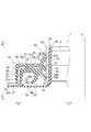
- FIG. 1 is a cross-sectional view for showing a schematic configuration of a sealing device 1 according to an embodiment of the present invention.
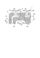
- FIG. 2 is an enlarged cross-sectional view for showing a schematic configuration in the vicinity of the through hole 24 and the positioning portion 36 of the sealing device 1.
- FIGS. 1 and 2 only one side portion of the sealing device 1 is shown.
- the sealing device 1 is used in a mud or dusty environment such as a railroad vehicle bogie, a sintered pallet bogie, a construction machine, a trunnion type suspension of a truck, and an agricultural machine (cultivator, tractor, rice transplanter, etc.).
- a mud or dusty environment such as a railroad vehicle bogie, a sintered pallet bogie, a construction machine, a trunnion type suspension of a truck, and an agricultural machine (cultivator, tractor, rice transplanter, etc.).
- the sealing device 1 has a role of sealing between an annular outer peripheral side member that can rotate relative to each other and an annular inner peripheral side member that is at least partially surrounded by the outer peripheral side member.
- the target to which the sealing device 1 is applied is not limited to the above.
- the sealing device 1 according to the embodiment of the present invention comprises an annular outer peripheral side member 101 that can rotate relative to each other on the axis Y1 and an annular inner peripheral side member 102 that is at least partially surrounded by the outer peripheral side member 101. It is a sealing device that seals between.
- the sealing device 1 includes a sealing device main body 10 attached to the outer peripheral side member 101, and a slinger 40 attached to the inner peripheral side member 102.
- the sealing device main body 10 includes an annular reinforcing ring 20 centered on the axis Y1 and an annular elastic body portion 30 centered on the axis Y1 made of an elastic body attached to the reinforcing ring 20.
- the reinforcing ring 20 is formed with a through hole 24 penetrating between the internal space side surface of the reinforcing ring 20 and the atmospheric side surface, and the internal space side surface of the elastic body portion 30 is formed by the reinforcing ring 20 during vulcanization.
- a positioning portion 36 for fixing the position is formed.
- the through hole 24 and the positioning portion 36 are formed at positions separated in the radial direction.
- the configuration of the sealing device 1 will be specifically described.
- one (arrow a direction) in the direction of the axis Y1 (hereinafter, also referred to as the axis Y1 direction), which is the axis of the sealing device 1 in FIGS.
- the direction of arrow b) is the atmosphere side.
- one (arrow c direction) in the direction extending orthogonal to the axis Y1 of the sealing device 1 in FIGS. 1 and 2 (hereinafter, also referred to as a radial direction) is the inner peripheral side, and the other (arrow d direction) is. It is on the outer peripheral side.
- the positional relationship and direction in the drawing are shown to the last, and the positional relationship and direction when incorporated in an actual vehicle or the like are not shown.
- the outer shape of the sealing device 1 is formed in an annular shape or a substantially annular shape around the axis Y1, and a cylindrical or substantially cylindrical opening 2 is formed in the central portion thereof. ing.
- the sealing device 1 is formed with an annular or substantially annular sealing device main body 10 around the axis Y1 and an inner peripheral side of the sealing device main body 10, and a cylindrical or substantially cylindrical slinger 40 around the axis Y1. have.
- the outer shape of the sealing device main body 10 is formed in an annular shape or a substantially annular shape around the axis Y1.
- the sealing device main body 10 is formed of an annular or substantially cylindrical reinforcing ring 20 around the axis Y1 and an elastic body integrally formed with the reinforcing ring 20, and is formed of an annular or substantially annular shape around the axis Y1. It has an elastic body portion 30.
- the elastic body of the elastic body portion 30 is, for example, a rubber material such as fluororubber or acrylic rubber.
- the reinforcing ring 20 is made of metal, for example, and is manufactured by press working or forging, and the elastic body portion 30 is molded by cross-linking (vulcanization) molding using a molding die.
- the reinforcing ring 20 includes a tubular portion 21, an annular inner peripheral side flange portion 22 extending inward from the internal space side end portion which is an end portion of the tubular portion 21 on the internal space side, and the tubular portion 21. It has an annular outer peripheral side flange portion 23 extending from the atmospheric side end portion, which is the atmospheric side end portion, to the outer peripheral side.
- the tubular portion 21 extends parallel to or substantially parallel to the axis Y1 direction, and is formed in a cylindrical or substantially cylindrical shape around the axis Y1.
- the tubular portion 21 has an internal space side end portion, an atmospheric side end portion, an inner peripheral side surface, and an outer peripheral side surface embedded in the elastic body portion 30.
- the inner peripheral side flange portion 22 extends parallel to or substantially parallel to the radial direction, and is an annular or substantially annular flange portion around the axis Y1 extending from the internal space side end portion of the tubular portion 21 to the inner peripheral side. is there.
- the inner space side surface, the atmospheric side surface, the inner peripheral side end portion, and the outer peripheral side end portion are embedded in the elastic body portion 30.
- a through hole 24 is formed in the central portion of the inner peripheral side flange portion 22 in the radial direction so as to penetrate between the inner space side surface and the atmospheric side surface of the inner peripheral side flange portion 22 of the reinforcing ring 20.
- the through holes 24 are formed, for example, in a cylindrical shape or a substantially cylindrical shape, and a plurality (for example, eight) of the through holes 24 are formed concentrically or substantially concentrically from the axis Y1 at equiangular intervals or substantially equiangular intervals.
- the diameter of the through hole 24 is, for example, 3 mm, and the through hole 24 is filled with the elastic body of the elastic body portion 30.
- the outer peripheral side flange portion 23 extends parallel to or substantially parallel to the radial direction, and is an annular or substantially annular flange portion around the axis Y1 extending from the atmospheric side end portion of the tubular portion 21 to the outer peripheral side.
- the inner peripheral side end portion (atmospheric side end portion of the tubular portion 21) and the atmospheric side surface are embedded in the elastic body portion 30, and most of the outer peripheral side end portion and the internal space side surface are elastic. It is exposed from the body part 30.
- the elastic body portion 30 has an internal space side elastic body portion 31, an atmospheric side elastic body portion 32, a seal lip portion 33, and a dust strip portion 34.
- the internal space side elastic body portion 31 extends in parallel or substantially parallel to the axis Y1 direction, and has a cylindrical or substantially cylindrical outer peripheral side portion 31d formed around the axis Y1 and a radial direction. It extends in parallel or substantially parallel, and has an annular or substantially annular internal space side portion 31a around an axis Y1 extending from the internal space side end portion of the outer peripheral side portion 31d to the outer peripheral side.
- the internal space side elastic body portion 31 is the outer peripheral side surface of the tubular portion 21, the internal space side end portion of the tubular portion 21 (the outer peripheral side end portion of the inner peripheral side flange portion 22), and the internal space of the inner peripheral side flange portion 22. It covers the sides.
- the elastic body portion 31 on the internal space side has an annular or substantially annular outer peripheral side lip portion 35 around the axis Y1 extending from the outer peripheral side portion 31d to the outer peripheral side.
- a positioning portion 36 for fixing the position of the reinforcing ring 20 during vulcanization is formed in the internal space side portion 31a of the internal space side elastic body portion 31.
- the positioning portion 36 is an annular groove portion formed on the outer peripheral side and / or the inner peripheral side of the through hole 24 and recessed from the internal space side to the atmospheric side.
- the positioning unit 36 has an inner peripheral side positioning unit 36c and an outer peripheral side positioning unit 36d.
- the inner peripheral side positioning portion 36c is located on the inner peripheral side of the through hole 24 from the internal space side surface 31aa of the internal space side portion 31a of the internal space side elastic body portion 31 to the inner peripheral side of the reinforcing ring 20. It is a groove portion having a rectangular shape or a substantially rectangular shape in a cross-sectional view that is recessed toward the side surface of the internal space of the flange portion 22. Further, the inner peripheral side positioning portion 36c is a peripheral groove formed in a bottomed cylindrical shape or a substantially bottomed cylindrical shape around the axis Y1.
- the inner peripheral side positioning portion 36c is an annular or substantially circular shape extending in parallel or substantially parallel to the radial direction from the internal space side surface 31aa of the internal space side portion 31a of the inner peripheral side positioning portion 36c to a position at a predetermined depth on the atmospheric side. It has an annular bottom surface of 36 ct. The bottom surface 36ct does not reach the inner space side surface of the inner peripheral side flange portion 22 of the reinforcing ring 20, and defines the boundary on the atmospheric side of the inner peripheral side positioning portion 36c.
- An inner peripheral side surface 36cc is formed on the inner peripheral side of the lower surface 36ct of the inner peripheral side positioning portion 36c, and an outer peripheral side surface 36cd is formed on the outer peripheral side of the lower surface 36ct of the inner peripheral side positioning portion 36c.
- the inner peripheral side surface 36cc of the inner peripheral side positioning portion 36c is a surface that defines the boundary on the inner peripheral side of the inner peripheral side positioning portion 36c, and the outer peripheral side surface 36cd of the inner peripheral side positioning portion 36c is the inner peripheral side positioning portion. It is a surface that defines the boundary on the outer peripheral side of 36c.
- the inner peripheral side surface 36cc of the inner peripheral side positioning portion 36c is a cylindrical or substantially cylindrical surface extending along the axis Y1 direction extending from the inner peripheral side edge of the bottom surface 36ct toward the internal space side with the axis Y1 as the center. is there.
- the outer peripheral side surface 36cd of the inner peripheral side positioning portion 36c is a cylindrical or substantially cylindrical surface extending from the outer peripheral side edge of the bottom surface 36ct toward the internal space side with the axis Y1 as the center along the axis Y1 direction.
- the outer peripheral side positioning portion 36d faces the inner space side surface of the inner peripheral side flange portion 22 of the reinforcing ring 20 from the internal space side surface 31aa of the internal space side portion 31a of the internal space side elastic body portion 31. It is a groove portion having a rectangular shape or a substantially rectangular shape in a cross-sectional view. Further, the outer peripheral side positioning portion 36d is a peripheral groove formed in a bottomed cylindrical shape or a substantially bottomed cylindrical shape around the axis Y1.
- the outer peripheral side positioning portion 36d is an annular shape or a substantially circular shape extending in parallel or substantially parallel to the radial direction from the internal space side surface 31aa of the internal space side portion 31a of the internal space side elastic body portion 31 to a position at a predetermined depth on the atmospheric side. It has an annular bottom surface of 36 dt. The bottom surface 36 dt does not reach the inner space side surface of the inner peripheral side flange portion 22 of the reinforcing ring 20, and defines the boundary of the outer peripheral side positioning portion 36 d on the atmospheric side.
- An inner peripheral side surface 36dc is formed on the inner peripheral side of the lower surface 36dt of the outer peripheral side positioning portion 36d, and an outer peripheral side surface 36dd is formed on the outer peripheral side of the bottom surface 36dt of the outer peripheral side positioning portion 36d.
- the inner peripheral side surface 36dc of the outer peripheral side positioning portion 36d is a surface that defines the boundary on the inner peripheral side of the outer peripheral side positioning portion 36d, and the outer peripheral side surface 36dd of the outer peripheral side positioning portion 36d is the outer peripheral side of the outer peripheral side positioning portion 36d. It is the surface that defines the boundary of.
- the inner peripheral side surface 36dc of the outer peripheral side positioning portion 36d is a cylindrical or substantially cylindrical surface extending along the axis Y1 direction extending from the inner peripheral side edge of the bottom surface 36dt toward the internal space side with the axis Y1 as the center. ..
- the outer peripheral side surface 36dd of the outer peripheral side positioning portion 36d is a cylindrical or substantially cylindrical surface extending from the outer peripheral side edge of the bottom surface 36dt toward the internal space side with the axis Y1 as the center along the axis Y1 direction.
- the through hole 24 and the positioning portion 36 are formed at positions separated in the radial direction.
- the outer peripheral side surface 36cd of the inner peripheral side positioning portion 36c is formed on the inner peripheral side of the peripheral surface of the through hole 24, and the inner peripheral side surface 36dc of the outer peripheral side positioning portion 36d is the circumference of the through hole 24. It is formed on the outer peripheral side of the surface. That is, a predetermined width W1 is formed between the outer peripheral side surface 36cd of the inner peripheral side positioning portion 36c and the peripheral surface of the through hole 24, and the inner peripheral side surface 36dc of the outer peripheral side positioning portion 36d and the through hole 24 A predetermined width W2 is formed between the peripheral surface and the peripheral surface.
- the entire surface of the bottom surface 36ct of the inner peripheral side positioning portion 36c and the bottom surface 36dt of the outer peripheral side positioning portion 36d faces the internal space side surface 22a of the inner peripheral side flange portion 22.
- the atmospheric side elastic body portion 32 extends parallel to or substantially parallel to the axis Y1 direction, and has an inner peripheral side portion 32c formed in a cylindrical or substantially cylindrical shape around the axis Y1. Further, the atmospheric side elastic body portion 32 extends parallel to or substantially parallel to the radial direction, and is an annular or substantially annular outer atmosphere around the axis Y1 extending from the atmospheric side end portion of the inner peripheral side portion 32c to the outer peripheral side. An annular or substantially annular inner peripheral atmosphere side portion extending around the axis Y1 extending from the internal space side end of the inner peripheral side portion 32c to the inner peripheral side, extending parallel to or substantially parallel to the side portion 32d. It has 32b and.
- the atmospheric side elastic body portion 32 includes the atmospheric side surface of the outer peripheral side flange portion 23 of the reinforcing ring 20, the inner peripheral side end portion of the outer peripheral side flange portion 23 (the atmospheric side end portion of the tubular portion 21), and the inner side of the tubular portion 21. It covers the peripheral side surface, the internal space side end portion of the tubular portion 21, the outer peripheral side end portion of the inner peripheral side flange portion 22, and the atmospheric side surface of the inner peripheral side flange portion 22.
- the thickness T1 of the inner peripheral atmosphere side portion 32b of the elastic body portion 30 formed on the atmospheric side of the reinforcing ring 20 is the thickness T2 of the internal space side portion 31a of the elastic body portion 30 formed on the internal space side of the reinforcing ring 20. Is thicker than.
- An atmospheric side positioning portion 37 for fixing the position of the reinforcing ring 20 at the time of vulcanization is formed on the outer peripheral atmospheric side surface of the outer peripheral atmospheric side portion 32d of the atmospheric side elastic body portion 32.
- the atmospheric side positioning portion 37 has a rectangular shape in a cross-sectional view that is recessed from the outer peripheral atmospheric side surface of the outer peripheral atmospheric side portion 32d toward the atmospheric side surface of the outer peripheral side flange portion 23 of the reinforcing ring 20 in the central portion in the radial direction of the outer peripheral atmospheric side portion 32d. Alternatively, it is a substantially rectangular groove. Further, the atmospheric side positioning portion 37 is a peripheral groove formed in a bottomed cylindrical shape or a substantially bottomed cylindrical shape around the axis Y1.
- the inner peripheral atmosphere side portion 32b of the atmospheric side elastic body portion 32 fills the through hole 24 of the inner peripheral side flange portion 22 of the reinforcing ring 20 with an elastic body, and the inner space side portion 31a of the internal space side elastic body portion 31.
- the reinforcing ring 20 and the elastic body portion 30 are connected to each other so that the adhesive force between the reinforcing ring 20 and the elastic body portion 30 can be improved.
- the seal lip portion 33 is formed in a truncated cone shape or a substantially truncated cone shape extending toward the internal space side from the inner peripheral side end portion of the internal space side portion 31a of the internal space side elastic body portion 31 toward the inner peripheral side.
- the tip has a lip tip 33a at the tip.
- the lip tip portion 33a is a wedge-shaped annular or substantially annular lip whose cross-sectional shape is convex toward the inner peripheral side, and is formed so as to be slidably in close contact with the slinger 40. Has been done.
- a garter spring 38 that presses the lip tip 33a toward the inner circumference in the radial direction is fitted on the outer peripheral side of the lip tip 33a.
- the dust strip portion 34 has a first dust strip portion 34a, a second dust strip portion 34b, and a third dust strip portion 34c in this order from the internal space side.
- the first dust strip portion 34a is a truncated cone-shaped or substantially truncated cone-shaped lip extending toward the atmosphere from the inner peripheral side end portion of the inner space side portion 31a of the inner space side elastic body portion 31 toward the inner peripheral side. , Is formed so as to be slidably in close contact with the slinger 40.
- the second dust strip portion 34b is a truncated cone-shaped or substantially truncated cone-shaped lip extending toward the atmosphere from the inner peripheral side end portion of the inner peripheral atmospheric side portion 32b of the atmospheric side elastic body portion 32 toward the inner peripheral side. , Is formed so as to be slidably in close contact with the slinger 40.
- the third dust strip portion 34c is a truncated cone-shaped or substantially truncated cone-shaped lip extending from the inner peripheral side end portion of the inner peripheral atmospheric side portion 32b of the atmospheric side elastic body portion 32 toward the atmospheric side toward the atmospheric side. It is formed so as to be slidably in close contact with the slinger 40.
- the slinger 40 is formed on the inner peripheral side of the sealing device main body 10, and the outer shape is formed in an annular shape or a substantially annular shape around the axis Y1.
- the slinger 40 is formed of an annular or substantially cylindrical reinforcing ring 50 around the axis Y1 and an elastic body integrally formed with the reinforcing ring 50, and is an annular or substantially annular elastic body around the axis Y1. It has a unit 60.
- the elastic body of the elastic body portion 60 is, for example, a rubber material such as fluororubber or acrylic rubber.
- the reinforcing ring 50 is made of metal, for example, and is manufactured by press working or forging, and the elastic body portion 60 is molded by cross-linking (vulcanization) molding using a molding die.
- the reinforcing ring 50 has a tubular portion 51 and an annular outer peripheral side flange portion 52 extending from the atmospheric side end portion 51b, which is the atmospheric side end portion of the tubular portion 51, to the outer peripheral side.
- the tubular portion 51 extends parallel to or substantially parallel to the axis Y1 direction, and is formed in a cylindrical or substantially cylindrical shape around the axis Y1.
- the atmosphere side end portion and the inner peripheral side surface are embedded in the elastic body portion 60, and the internal space side end portion and the outer peripheral side surface are exposed from the elastic body portion 60.
- the outer peripheral side surface of the tubular portion 51 is slidably in close contact with the seal lip portion 33, the first dust strip portion 34a, and the second dust strip portion 34b.
- the outer peripheral side flange portion 52 extends parallel to or substantially parallel to the radial direction, and is an annular or substantially annular flange portion around the axis Y1 extending from the atmospheric side end portion of the tubular portion 51 to the outer peripheral side.
- the outer peripheral side end portion, the inner peripheral side end portion (the atmospheric side end portion of the tubular portion 51) and the atmospheric side surface are buried in the elastic body portion 60, and the internal space side surface is the elastic body portion 60. It is exposed from.
- the internal space side surface 52a of the outer peripheral side flange portion 52 is slidably in close contact with the third dust strip portion 34c.
- the elastic body portion 60 extends parallel to or substantially parallel to the axis Y1 direction, and extends parallel to or substantially parallel to the radial direction with the inner peripheral side portion 61 formed in a cylindrical or substantially cylindrical shape around the axis Y1. It has an annular or substantially annular atmospheric side portion 62 around an axis Y1 extending from the atmospheric side end of the inner peripheral side portion 61 to the outer peripheral side. Further, the elastic body portion 60 has an annular or substantially annular inner peripheral side lip portion 63 around the axis Y1 extending from the inner peripheral side portion 61 to the inner peripheral side.
- the inner peripheral side portion 61 of the elastic body portion 60 covers the inner peripheral side surface and the atmospheric side end portion of the tubular portion 51.
- the atmospheric side portion 62 of the elastic body portion 60 covers the inner peripheral side end portion (atmospheric side end portion of the inner peripheral side portion 61), the atmospheric side surface, and the outer peripheral side end portion of the atmospheric side portion 62.
- the outer peripheral side end of the atmospheric side portion 62 of the elastic body portion 60 faces the outer peripheral atmospheric side portion 32d of the atmospheric side elastic body portion 32 of the elastic body portion 30 with a predetermined gap, and the elastic body portion 60
- a gap G is formed between the outer peripheral side end portion of the atmospheric side portion 62 and the outer peripheral atmospheric side portion 32d of the atmospheric side elastic body portion 32.
- FIG. 3 is a cross-sectional view showing a schematic configuration of a sealing structure 100 in which the sealing device 1 according to the embodiment of the present invention is assembled to a sealing target.
- the sealing structure 100 is a sealing device in an annular gap between an annular outer peripheral member 101 that can rotate relative to each other on the axis Y1 and an annular inner peripheral member 102 that is at least partially surrounded by the outer peripheral member 101. 1 is assembled and configured, and an annular gap between the outer peripheral side member 101 and the inner peripheral side member 102 is sealed.
- the inner peripheral side member 102 extends parallel or substantially parallel to the axis Y1 direction, and extends parallel or substantially parallel to the radial direction with the rod-shaped portion 103 formed in the shape of a cylindrical rod or substantially a cylindrical rod around the axis Y1.
- the rod-shaped portion 103 has an annular or substantially annular outer peripheral side flange portion 104 around an axis Y1 extending from the atmospheric side end portion 103b to the outer peripheral side.
- the outer peripheral side member 101 is arranged on the outer peripheral side of the inner peripheral side member 102, and the outer peripheral side member 101 is formed with a cylindrical or substantially cylindrical opening 105 around the axis Y1.
- An inner peripheral side member 102 is inserted into the opening 105 of the outer peripheral side member 101, and an annular space is formed between the opening 105 and the outer peripheral side surface of the rod-shaped portion 103 of the inner peripheral side member 102. .. That is, the outer peripheral side member 101, the rod-shaped portion 103 of the inner peripheral side member 102, and the outer peripheral side flange portion 104 form an accommodating portion 106 for accommodating the sealing device 1.
- the accommodating portion 106 is recessed from the internal space side of the outer peripheral side member 101 and the inner peripheral side member 102 toward the atmosphere side, and a predetermined space is provided between the outer peripheral side member 101 and the outer peripheral side flange portion 104 of the inner peripheral side member 102. The gap is formed.
- the slinger 40 of the sealing device 1 is fixed to the outer peripheral side surface of the rod-shaped portion 103 of the inner peripheral side member 102 by the inner peripheral side lip portion 63 of the inner peripheral side portion 61 of the elastic body portion 60, for example, by closing and fitting.
- the atmospheric side portion 62 of the elastic body portion 60 is in close contact with the internal space side surface of the outer peripheral side flange portion 104 of the inner peripheral side member 102.
- the sealing device main body 10 of the sealing device 1 is fixed to the opening 105 of the outer peripheral side member 101 by the outer peripheral side lip portion 35 of the internal space side elastic body portion 31 of the elastic body portion 30, for example, by closing and fitting.
- the inner space side surface of the outer peripheral side flange portion 23 of 10 is in close contact with the atmospheric side end portion of the outer peripheral side member 101.
- the seal lip portion 33 in the elastic body portion 30 of the sealing device main body 10 of the sealing device 1, the first dust strip portion 34a and the second dust strip portion 34b of the dust strip portion 34 are the outer peripheral side surfaces of the tubular portion 51 of the slinger 40. It is closely slidable. Further, the third dust strip portion 34c of the dust strip portion 34 is slidably in close contact with the internal space side surface of the outer peripheral side flange portion 52 of the slinger 40.
- a gap G is formed between the outer peripheral side end of the inner peripheral side portion 61 of the elastic body portion 60 and the outer peripheral atmospheric side portion 32d of the atmospheric side elastic body portion 32, and the outer peripheral side end of the inner peripheral side portion 61 is formed.
- a predetermined gap between the outer peripheral side member 101 and the outer peripheral side flange portion 104 of the inner peripheral side member 102 is reduced by the portion and the outer peripheral atmospheric side portion 32d of the atmospheric side elastic body portion 32.
- the sealing device 1 is assembled to the annular gap between the outer peripheral side member 101 and the annular inner peripheral side member 102 that is at least partially surrounded, so that the outer peripheral side member 101 and the inner peripheral side member 101 are assembled. It is possible to seal the annular gap between the peripheral member 102 and the peripheral member 102.
- the sealing device main body 10 is an annular elastic body centered on the axis Y1 composed of an annular reinforcing ring 20 centered on the axis Y1 and an elastic body attached to the reinforcing ring 20. It is provided with a unit 30.
- the reinforcing ring 20 is formed with a through hole 24 penetrating between the internal space side surface of the reinforcing ring 20 and the atmospheric side surface, and the internal space side surface of the elastic body portion 30 is formed by the reinforcing ring 20 during vulcanization.
- a positioning portion 36 for fixing the position is formed.
- the through hole 24 and the positioning portion 36 are formed at positions separated in the radial direction.
- the positioning portion 36 which is a portion where the thickness of the rubber material of the elastic body portion 30 is thin, due to the swelling and contraction of the rubber material of the elastic body portion 30 due to the adhesion of the solvent, it penetrates. Since the hole 24 and the positioning portion 36 are separated in the radial direction, the crack generated from the positioning portion 36 is stopped by the reinforcing ring 20, and it is possible to suppress the formation of a through crack through the through hole 24.
- the thickness T1 of the inner peripheral atmospheric side portion 32b of the elastic body portion 30 formed on the atmospheric side of the reinforcing ring 20 is the inside of the elastic body portion 30 formed on the internal space side of the reinforcing ring 20. It is thicker than the thickness T2 of the space side portion 31a. Therefore, it is possible to further suppress the formation of a through crack through the through hole 24.
- the positioning portion 36 is an annular groove portion formed on the outer peripheral side and / or the inner peripheral side of the through hole 24 and recessed from the internal space side to the atmospheric side. Therefore, the position of the reinforcing ring 20 at the time of vulcanization can be easily fixed.
- the through holes 24 are formed, for example, in a cylindrical shape or a substantially cylindrical shape, and are concentric or substantially concentric intervals from the axis Y1.
- the embodiment of the present invention has been described as an example in the case where a plurality (for example, eight) are formed.
- the present invention is not limited to this, and the through hole 24 may be a hole having an arbitrary shape, and the position, number, and size of the holes are also formed at an arbitrary position, number, and size. Just do it.
- the positioning portion 36 is an annular groove portion formed on the outer peripheral side and / or the inner peripheral side of the through hole 24 and recessed from the internal space side to the atmospheric side.
- the embodiment of the present invention has been described as an example. However, the present invention is not limited to this, and any shape may be used as long as the position of the reinforcing ring 20 at the time of vulcanization can be fixed.
- Sealing device 10 ... Sealing device body, 20 ... Reinforcing ring, 30 ... Elastic body part, 24 ... Through hole, 36 ... Positioning part, 40 ... Slinger, 100 ... Sealing structure, 101 ... Outer peripheral side member, 102 ... Peripheral member, G ... Gap, Y1 ... Axis
Landscapes
- Engineering & Computer Science (AREA)
- General Engineering & Computer Science (AREA)
- Mechanical Engineering (AREA)
- Manufacturing & Machinery (AREA)
- Sealing With Elastic Sealing Lips (AREA)
- Sealing Devices (AREA)
Abstract
Description
Claims (3)
- 軸線において互いに相対回転可能な環状の外周側部材と、該外周側部材に少なくとも部分的に包囲された環状の内周側部材との間を密封する密封装置であって、
前記外周側部材に取り付けられる密封装置本体と、
前記内周側部材に取り付けられるスリンガとを備え、
前記密封装置本体は、前記軸線を中心とする環状の補強環と、該補強環に取り付けられた弾性体からなる前記軸線を中心とする環状の弾性体部とを備え、
前記補強環には、該補強環の内部空間側面と大気側面との間を貫通する貫通孔が形成されており、
前記弾性体部の内部空間側面には、加硫時における前記補強環の位置を固定するための位置決め部が形成されており、
前記貫通孔と前記位置決め部とが径方向において離れた位置に形成されていることを特徴とする密封装置。 - 前記補強環の大気側に形成される前記弾性体部の厚みは、前記補強環の内部空間側に形成される前記弾性体部の厚みよりも厚くなっていることを特徴とする請求項1記載の密封装置。
- 前記位置決め部は、前記貫通孔の外周側及び/又は内周側に形成される内部空間側から大気側に凹む環状の溝部であることを特徴とする請求項1又は2記載の密封装置。
Priority Applications (4)
| Application Number | Priority Date | Filing Date | Title |
|---|---|---|---|
| EP20818041.4A EP3982016A4 (en) | 2019-06-05 | 2020-05-13 | Sealing device |
| JP2021524725A JP7319364B2 (ja) | 2019-06-05 | 2020-05-13 | 密封装置 |
| US17/604,090 US11906049B2 (en) | 2019-06-05 | 2020-05-13 | Sealing device |
| CN202080027877.3A CN113677917B (zh) | 2019-06-05 | 2020-05-13 | 密封装置 |
Applications Claiming Priority (2)
| Application Number | Priority Date | Filing Date | Title |
|---|---|---|---|
| JP2019105378 | 2019-06-05 | ||
| JP2019-105378 | 2019-06-05 |
Publications (1)
| Publication Number | Publication Date |
|---|---|
| WO2020246206A1 true WO2020246206A1 (ja) | 2020-12-10 |
Family
ID=73652799
Family Applications (1)
| Application Number | Title | Priority Date | Filing Date |
|---|---|---|---|
| PCT/JP2020/019064 Ceased WO2020246206A1 (ja) | 2019-06-05 | 2020-05-13 | 密封装置 |
Country Status (5)
| Country | Link |
|---|---|
| US (1) | US11906049B2 (ja) |
| EP (1) | EP3982016A4 (ja) |
| JP (1) | JP7319364B2 (ja) |
| CN (1) | CN113677917B (ja) |
| WO (1) | WO2020246206A1 (ja) |
Cited By (1)
| Publication number | Priority date | Publication date | Assignee | Title |
|---|---|---|---|---|
| WO2023167103A1 (ja) * | 2022-03-04 | 2023-09-07 | Nok株式会社 | 密封装置及び密封構造 |
Citations (4)
| Publication number | Priority date | Publication date | Assignee | Title |
|---|---|---|---|---|
| JPH0385761U (ja) * | 1989-12-15 | 1991-08-29 | ||
| JP4978074B2 (ja) | 2006-06-19 | 2012-07-18 | Nok株式会社 | 密封装置 |
| JP2015059644A (ja) * | 2013-09-20 | 2015-03-30 | Ntn株式会社 | 密封装置およびこれを備えた車輪用軸受装置 |
| JP2015098881A (ja) * | 2013-11-18 | 2015-05-28 | Nok株式会社 | 密封装置の製造方法 |
Family Cites Families (13)
| Publication number | Priority date | Publication date | Assignee | Title |
|---|---|---|---|---|
| JPS60194665U (ja) * | 1984-06-06 | 1985-12-25 | 株式会社 荒井製作所 | オイルシ−ル |
| JP2804517B2 (ja) | 1989-06-15 | 1998-09-30 | エヌオーケー株式会社 | オイルシール用スリンガー付スリーブおよびそのシール組立体 |
| JP2005226826A (ja) | 2004-01-14 | 2005-08-25 | Nsk Ltd | 転がり軸受 |
| DE602005020219D1 (de) * | 2004-07-09 | 2010-05-12 | Freudenberg Carl Kg | Wellendichtring |
| KR20060131366A (ko) * | 2005-06-16 | 2006-12-20 | 주식회사 이노씰 | 씰 |
| WO2009078314A1 (ja) * | 2007-12-17 | 2009-06-25 | Nok Corporation | 密封装置 |
| JP4953022B2 (ja) | 2008-03-07 | 2012-06-13 | 株式会社ジェイテクト | 軸受用密封装置 |
| JP2010185465A (ja) | 2009-02-10 | 2010-08-26 | Nsk Ltd | 組み合わせシールリング付転がり軸受ユニット |
| DE102011002491A1 (de) * | 2011-01-11 | 2012-07-12 | Aktiebolaget Skf | Radialwellendichtring |
| JP5704316B2 (ja) * | 2011-01-14 | 2015-04-22 | Nok株式会社 | オイルシール |
| JP2014126105A (ja) * | 2012-12-26 | 2014-07-07 | Nsk Ltd | 車輪支持用転がり軸受ユニット |
| JP6610166B2 (ja) | 2015-01-21 | 2019-11-27 | 日本精工株式会社 | ハブユニット軸受 |
| CN206682305U (zh) * | 2017-03-01 | 2017-11-28 | 舍弗勒技术股份两合公司 | 盒式密封装置 |
-
2020
- 2020-05-13 US US17/604,090 patent/US11906049B2/en active Active
- 2020-05-13 EP EP20818041.4A patent/EP3982016A4/en active Pending
- 2020-05-13 CN CN202080027877.3A patent/CN113677917B/zh active Active
- 2020-05-13 JP JP2021524725A patent/JP7319364B2/ja active Active
- 2020-05-13 WO PCT/JP2020/019064 patent/WO2020246206A1/ja not_active Ceased
Patent Citations (4)
| Publication number | Priority date | Publication date | Assignee | Title |
|---|---|---|---|---|
| JPH0385761U (ja) * | 1989-12-15 | 1991-08-29 | ||
| JP4978074B2 (ja) | 2006-06-19 | 2012-07-18 | Nok株式会社 | 密封装置 |
| JP2015059644A (ja) * | 2013-09-20 | 2015-03-30 | Ntn株式会社 | 密封装置およびこれを備えた車輪用軸受装置 |
| JP2015098881A (ja) * | 2013-11-18 | 2015-05-28 | Nok株式会社 | 密封装置の製造方法 |
Non-Patent Citations (1)
| Title |
|---|
| See also references of EP3982016A4 |
Cited By (2)
| Publication number | Priority date | Publication date | Assignee | Title |
|---|---|---|---|---|
| WO2023167103A1 (ja) * | 2022-03-04 | 2023-09-07 | Nok株式会社 | 密封装置及び密封構造 |
| US12442418B2 (en) | 2022-03-04 | 2025-10-14 | Nok Corporation | Sealing device and sealing structure |
Also Published As
| Publication number | Publication date |
|---|---|
| EP3982016A1 (en) | 2022-04-13 |
| US20220205539A1 (en) | 2022-06-30 |
| JP7319364B2 (ja) | 2023-08-01 |
| JPWO2020246206A1 (ja) | 2020-12-10 |
| CN113677917B (zh) | 2025-01-14 |
| EP3982016A4 (en) | 2023-06-28 |
| US11906049B2 (en) | 2024-02-20 |
| CN113677917A (zh) | 2021-11-19 |
Similar Documents
| Publication | Publication Date | Title |
|---|---|---|
| KR101873175B1 (ko) | 밀봉구조 | |
| US10746229B2 (en) | Wheel bearing sealing device and manufacturing method therefor | |
| US3479840A (en) | Trunnion seal for cardan-type universal joint | |
| US3813102A (en) | Locking and sealing ring | |
| JPWO2020250579A5 (ja) | ||
| US10634193B2 (en) | Rotary seal | |
| CN104641134A (zh) | 具有密封组件的滚动轴承 | |
| CN103370564B (zh) | 滑环密封件 | |
| JP7319364B2 (ja) | 密封装置 | |
| JP6679914B2 (ja) | 密封装置 | |
| KR20150136024A (ko) | 카세트형 씰 | |
| JP7065037B2 (ja) | 密封装置 | |
| JP6123945B2 (ja) | 密封構造 | |
| KR101734691B1 (ko) | 휨 방지수단을 구비한 베어링용 플링거 | |
| JP6868386B2 (ja) | 密封装置 | |
| CA2974717A1 (en) | Sealing device | |
| JP2009002425A (ja) | 密封装置 | |
| JP2017048871A (ja) | 密封装置 | |
| JP2019108898A (ja) | 密封装置 | |
| JP6804362B2 (ja) | 密封装置 | |
| CN105179466A (zh) | 滚动轴承,特别是用于离合器分离轴承装置的滚动轴承 | |
| CN113969942A (zh) | 离合器分离轴承和用于离合器分离轴承的滚动轴承 | |
| JP2009085419A (ja) | 密封装置 | |
| US11846354B2 (en) | Sealing device | |
| JP2020118233A (ja) | 密封装置 |
Legal Events
| Date | Code | Title | Description |
|---|---|---|---|
| 121 | Ep: the epo has been informed by wipo that ep was designated in this application |
Ref document number: 20818041 Country of ref document: EP Kind code of ref document: A1 |
|
| ENP | Entry into the national phase |
Ref document number: 2021524725 Country of ref document: JP Kind code of ref document: A |
|
| NENP | Non-entry into the national phase |
Ref country code: DE |
|
| ENP | Entry into the national phase |
Ref document number: 2020818041 Country of ref document: EP Effective date: 20220105 |
|
| WWG | Wipo information: grant in national office |
Ref document number: 202080027877.3 Country of ref document: CN |