WO2020246251A1 - 情報処理装置および方法、並びに、プログラム - Google Patents
情報処理装置および方法、並びに、プログラム Download PDFInfo
- Publication number
- WO2020246251A1 WO2020246251A1 PCT/JP2020/020062 JP2020020062W WO2020246251A1 WO 2020246251 A1 WO2020246251 A1 WO 2020246251A1 JP 2020020062 W JP2020020062 W JP 2020020062W WO 2020246251 A1 WO2020246251 A1 WO 2020246251A1
- Authority
- WO
- WIPO (PCT)
- Prior art keywords
- information
- unit
- moving body
- target
- event
- Prior art date
- Legal status (The legal status is an assumption and is not a legal conclusion. Google has not performed a legal analysis and makes no representation as to the accuracy of the status listed.)
- Ceased
Links
Images






Classifications
-
- G—PHYSICS
- G08—SIGNALLING
- G08B—SIGNALLING SYSTEMS, e.g. PERSONAL CALLING SYSTEMS; ORDER TELEGRAPHS; ALARM SYSTEMS
- G08B13/00—Burglar, theft or intruder alarms
- G08B13/18—Actuation by interference with heat, light, or radiation of shorter wavelength; Actuation by intruding sources of heat, light, or radiation of shorter wavelength
- G08B13/189—Actuation by interference with heat, light, or radiation of shorter wavelength; Actuation by intruding sources of heat, light, or radiation of shorter wavelength using passive radiation detection systems
- G08B13/194—Actuation by interference with heat, light, or radiation of shorter wavelength; Actuation by intruding sources of heat, light, or radiation of shorter wavelength using passive radiation detection systems using image scanning and comparing systems
- G08B13/196—Actuation by interference with heat, light, or radiation of shorter wavelength; Actuation by intruding sources of heat, light, or radiation of shorter wavelength using passive radiation detection systems using image scanning and comparing systems using television cameras
- G08B13/19639—Details of the system layout
- G08B13/19647—Systems specially adapted for intrusion detection in or around a vehicle
-
- G—PHYSICS
- G06—COMPUTING OR CALCULATING; COUNTING
- G06V—IMAGE OR VIDEO RECOGNITION OR UNDERSTANDING
- G06V20/00—Scenes; Scene-specific elements
- G06V20/10—Terrestrial scenes
- G06V20/17—Terrestrial scenes taken from planes or by drones
-
- B—PERFORMING OPERATIONS; TRANSPORTING
- B64—AIRCRAFT; AVIATION; COSMONAUTICS
- B64U—UNMANNED AERIAL VEHICLES [UAV]; EQUIPMENT THEREFOR
- B64U10/00—Type of UAV
- B64U10/60—Tethered aircraft
-
- B—PERFORMING OPERATIONS; TRANSPORTING
- B64—AIRCRAFT; AVIATION; COSMONAUTICS
- B64U—UNMANNED AERIAL VEHICLES [UAV]; EQUIPMENT THEREFOR
- B64U70/00—Launching, take-off or landing arrangements
- B64U70/90—Launching from or landing on platforms
- B64U70/92—Portable platforms
-
- G—PHYSICS
- G05—CONTROLLING; REGULATING
- G05D—SYSTEMS FOR CONTROLLING OR REGULATING NON-ELECTRIC VARIABLES
- G05D1/00—Control of position, course, altitude or attitude of land, water, air or space vehicles, e.g. using automatic pilots
- G05D1/12—Target-seeking control
-
- G—PHYSICS
- G06—COMPUTING OR CALCULATING; COUNTING
- G06T—IMAGE DATA PROCESSING OR GENERATION, IN GENERAL
- G06T7/00—Image analysis
- G06T7/20—Analysis of motion
-
- G—PHYSICS
- G06—COMPUTING OR CALCULATING; COUNTING
- G06V—IMAGE OR VIDEO RECOGNITION OR UNDERSTANDING
- G06V20/00—Scenes; Scene-specific elements
- G06V20/50—Context or environment of the image
- G06V20/52—Surveillance or monitoring of activities, e.g. for recognising suspicious objects
-
- G—PHYSICS
- G08—SIGNALLING
- G08B—SIGNALLING SYSTEMS, e.g. PERSONAL CALLING SYSTEMS; ORDER TELEGRAPHS; ALARM SYSTEMS
- G08B13/00—Burglar, theft or intruder alarms
- G08B13/18—Actuation by interference with heat, light, or radiation of shorter wavelength; Actuation by intruding sources of heat, light, or radiation of shorter wavelength
- G08B13/189—Actuation by interference with heat, light, or radiation of shorter wavelength; Actuation by intruding sources of heat, light, or radiation of shorter wavelength using passive radiation detection systems
- G08B13/194—Actuation by interference with heat, light, or radiation of shorter wavelength; Actuation by intruding sources of heat, light, or radiation of shorter wavelength using passive radiation detection systems using image scanning and comparing systems
- G08B13/196—Actuation by interference with heat, light, or radiation of shorter wavelength; Actuation by intruding sources of heat, light, or radiation of shorter wavelength using passive radiation detection systems using image scanning and comparing systems using television cameras
- G08B13/19639—Details of the system layout
- G08B13/19647—Systems specially adapted for intrusion detection in or around a vehicle
- G08B13/1965—Systems specially adapted for intrusion detection in or around a vehicle the vehicle being an aircraft
-
- H—ELECTRICITY
- H04—ELECTRIC COMMUNICATION TECHNIQUE
- H04N—PICTORIAL COMMUNICATION, e.g. TELEVISION
- H04N7/00—Television systems
- H04N7/18—Closed-circuit television [CCTV] systems, i.e. systems in which the video signal is not broadcast
- H04N7/183—Closed-circuit television [CCTV] systems, i.e. systems in which the video signal is not broadcast for receiving images from a single remote source
- H04N7/185—Closed-circuit television [CCTV] systems, i.e. systems in which the video signal is not broadcast for receiving images from a single remote source from a mobile camera, e.g. for remote control
-
- B—PERFORMING OPERATIONS; TRANSPORTING
- B64—AIRCRAFT; AVIATION; COSMONAUTICS
- B64U—UNMANNED AERIAL VEHICLES [UAV]; EQUIPMENT THEREFOR
- B64U2101/00—UAVs specially adapted for particular uses or applications
- B64U2101/30—UAVs specially adapted for particular uses or applications for imaging, photography or videography
-
- B—PERFORMING OPERATIONS; TRANSPORTING
- B64—AIRCRAFT; AVIATION; COSMONAUTICS
- B64U—UNMANNED AERIAL VEHICLES [UAV]; EQUIPMENT THEREFOR
- B64U2201/00—UAVs characterised by their flight controls
- B64U2201/10—UAVs characterised by their flight controls autonomous, i.e. by navigating independently from ground or air stations, e.g. by using inertial navigation systems [INS]
-
- B—PERFORMING OPERATIONS; TRANSPORTING
- B64—AIRCRAFT; AVIATION; COSMONAUTICS
- B64U—UNMANNED AERIAL VEHICLES [UAV]; EQUIPMENT THEREFOR
- B64U2201/00—UAVs characterised by their flight controls
- B64U2201/20—Remote controls
- B64U2201/202—Remote controls using tethers for connecting to ground station
-
- G—PHYSICS
- G06—COMPUTING OR CALCULATING; COUNTING
- G06T—IMAGE DATA PROCESSING OR GENERATION, IN GENERAL
- G06T2207/00—Indexing scheme for image analysis or image enhancement
- G06T2207/10—Image acquisition modality
- G06T2207/10032—Satellite or aerial image; Remote sensing
-
- G—PHYSICS
- G06—COMPUTING OR CALCULATING; COUNTING
- G06T—IMAGE DATA PROCESSING OR GENERATION, IN GENERAL
- G06T2207/00—Indexing scheme for image analysis or image enhancement
- G06T2207/30—Subject of image; Context of image processing
- G06T2207/30232—Surveillance
Definitions
- the present disclosure relates to information processing devices and methods and programs, and in particular, to information processing devices and methods and programs capable of providing more useful support for the activity of a target moving object.
- a designated range monitoring system that monitors the intrusion of a person or another vehicle into a designated range around the vehicle has been considered (see, for example, Patent Document 1).
- the monitoring range can be freely set in the captured image based on the operator's operation, signs, and the like.
- the priority of each of the plurality of photographing devices is determined based on the position of the specified priority monitoring target, and the processing related to the image for photographing the monitoring area is the priority determined for the photographing device for photographing the image.
- a method of determining according to the degree has also been considered (see, for example, Patent Document 2). In the case of this method, the position measured by the companion terminal possessed by the companion can be specified as the position in the monitoring area of the priority monitoring target.
- Patent Document 1 when the subject of the activity to be supported is a moving body (also referred to as a target moving body), a region at a predetermined relative position with respect to the target moving body is monitored. It was difficult.
- This disclosure has been made in view of such circumstances, and is intended to enable more useful support for the activity of the target moving object.
- the information processing device of one aspect of the present technology is capable of detecting predetermined information by the moving body based on the target moving body-related information about the target moving body detected by the moving body, and is a predetermined device based on the target moving body. It is an information processing apparatus including a setting unit that sets a predetermined area at a relative position as a monitoring target area.
- the information processing method of one aspect of the present technology is a predetermined information processing method based on the target moving body, which can detect predetermined information by the moving body based on the target moving body-related information about the target moving body detected by the moving body.
- This is an information processing method for setting a predetermined area at a relative position as a monitoring target area.
- a program of one aspect of the present technology allows a computer to detect predetermined information by the moving body based on the target moving body-related information about the target moving body detected by the moving body, based on the target moving body. It is a program that functions as a setting unit that sets a predetermined area at a relative position of the monitoring target area.
- a target whose predetermined information can be detected by the moving body based on the target moving body-related information about the target moving body detected by the moving body.
- a predetermined area at a predetermined relative position with respect to the moving body is set as a monitoring target area.
- a monitoring system for monitoring an area for example, there is a designated range monitoring system for monitoring the intrusion of a person, another vehicle, or the like into a designated range around a vehicle, as described in Patent Document 1.
- the monitoring range can be freely set in the captured image based on the operator's operation, signs, and the like.
- the priority of each of a plurality of photographing devices is determined based on the position of the specified priority monitoring target, and the image in which the monitoring area is photographed is determined.
- the priority of the photographing apparatus can be updated according to the position of the monitoring target.
- Patent Document 1 and Patent Document 2 when the subject of the activity to be supported is a moving body (also referred to as a target moving body), a region at a predetermined relative position with respect to the target moving body is monitored. It was difficult. For example, in the method described in Patent Document 1, the case where the object is a moving object is not considered. In addition, only a bird's-eye view was taken from above the vehicle, and the field of view (blind spot) of the target was not taken into consideration. Further, for example, in the case of the method described in Patent Document 2, only the priority imaging device is selected according to the position of the companion terminal, and the position relative to the target moving object by the observer terminal or the fixed camera is used. Shooting of the area was not guaranteed. In addition, the field of view (blind spot) of the subject was not considered.
- a predetermined area at a predetermined relative position with respect to the target moving body is monitored so that the moving body can detect the predetermined information.
- Set it as the target area For example, in an information processing device, it is at a predetermined relative position with respect to the target moving body, which can detect predetermined information by the moving body based on the target moving body-related information about the target moving body detected by the moving body.
- a setting unit for setting a predetermined area as a monitoring target area is provided.
- the program causes the computer to be placed in a predetermined relative position relative to the target moving body, which can detect predetermined information by the moving body based on the target moving body-related information about the target moving body detected by the moving body. It is made to function as a setting unit for setting a predetermined area as a monitoring target area.
- the target moving body can be more easily used.
- a predetermined area at a predetermined relative position with respect to the above can be set as a monitoring target area. That is, it is possible to more easily obtain information (monitor the area) from a region at a desired relative position of the target moving object, and to support the activity of the target moving object based on the information.
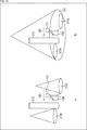
- the area that becomes the blind spot of the target moving object is an area in which it is difficult to obtain information from the target moving object.
- the blind spot indicates an area that cannot be seen from the subject (police officer 113) due to, for example, the visual field limit of the subject (police officer 113) or an obstacle obstructing the object.
- the rear side of the police officer 113 in the opposite direction of the face or the line of sight of the police officer 113) is out of the field of view of the police officer 113 and becomes a blind spot.
- the field of view may be obstructed by a wall or the like, resulting in a blind spot. Information generated in such blind spots tends to be difficult for police officers to grasp.
- the monitoring target area so as to include such a blind spot of the target moving object
- the blind spot of the target moving body can be monitored. Then, by notifying the target moving body of an event (event related to the activity performed by the target movement) that occurs in the blind spot of the target moving body, it is possible to notify the target moving body of information that is difficult for the target moving body to obtain. In other words, it is possible to provide more useful support for the activities performed by the target moving object.
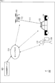
- FIG. 1 is a block diagram showing an example of a main configuration of a patrol support system, which is an aspect of an information processing system to which the present technology is applied.
- the patrol support system 100 shown in FIG. 1 is a system that supports patrol of police officers by taking an image and using the obtained image.
- the patrol support system 100 includes a patrol car 101, a base station 102, an air vehicle 103, a terminal device 104, and a central control server 105.
- the patrol car 101 is a vehicle on which the police officer 113 rides, and the police officer 113 performs operations such as driving. In addition to having a function as a normal vehicle, the patrol car 101 also has equipment peculiar to police vehicles such as a rotating light (also referred to as a red light or a light bar) and a wireless communication device. Further, the patrol car 101 includes a base station 102.
- the base station 102 is a control device that controls the flying object 103, and is a device that serves as an airfield for the flying object 103.
- the base station 102 and the flying object 103 are connected to each other by a cable 111 in order to physically limit the flight range of the flying object 103.
- the base station 102 has a communication function and can communicate with other devices such as a patrol car 101, an air vehicle 103, a terminal device 104, or a central control server 105.
- These communication methods are arbitrary, and may be wireless communication, wired communication, or both.
- the base station 102 and the aircraft 103 may communicate via the cable 111 (wired communication), or may perform wireless communication without the cable 111.
- the cable 111 may or may not be a communication medium.
- the base station 102 may be able to wind the cable 111 so that the cable 111 does not loosen.
- the length of the cable 111 may be variable, and the flight restriction range of the flying object 103 may be variable.
- Aircraft 103 is an unmanned aerial vehicle such as a so-called drone.
- the aircraft body 103 uses the base station 102 as a takeoff and landing ground and flies within the flight restriction range by the cable 111.
- the flying object 103 can fly autonomously or fly (remotely controlled) under the control of other devices (or other devices) such as the base station 102, the terminal device 104, and the central control server 105. You can also do it.
- the flying object 103 is provided with an arbitrary sensor, and the sensor can detect arbitrary information.
- the flying object 103 may include a camera 112 as its sensor and have an imaging function.
- the flying object 103 can take an image while flying by using the camera 112 (imaging function unit). That is, the flying object 103 is an imaging range variable unit that makes the imaging range of the camera 112 variable (controls the imaging range). This imaging can be performed autonomously or can be controlled by another device such as the base station 102.
- the flying object 103 images the surroundings of a patrol car 101, a police officer 113, etc. during patrol while flying, depending on the situation.
- the captured image can be used for any purpose.
- this captured image may be used for controlling any other device such as the patrol car 101, the flying object 103, and the terminal device 104.
- the captured image may be used to support patrol activities such as recording and guidance.
- the camera 112 includes a flying object 103 and has a flight function. That is, the flying object 103 and the camera 112 can be said to be an aircraft (aircraft) having an imaging function unit and a variable imaging range unit, and can also be said to be an imaging device including an imaging function unit and a variable imaging range unit.
- the terminal device 104 is an electronic device carried by a police officer 113 who is a user (driver, crew member) of the patrol car 101.
- the terminal device 104 may be a portable terminal device such as a smartphone or a tablet device.
- the terminal device 104 may be a wearable device such as a wristwatch type, an eyeglass type, a ring type, a shoe type, a pocket type, or a pendant type.
- the terminal device 104 includes an arbitrary sensor, and the sensor can detect arbitrary information.
- the terminal device 104 may have an imaging function such as a camera to capture an image of a subject.
- the terminal device 104 carried by the police officer 113 on patrol images the situation around the police officer 113.
- This captured image can be used for any purpose.
- this captured image may be used for controlling any other device such as a patrol car 101 or an air vehicle 103.
- the terminal device 104 may use a sensor to detect the use of weapons and tools by the police officer 113, and the biological information of the police officer 113 such as pulse, heart rate, and line-of-sight direction.
- This detected information can be used for any purpose.
- this sensor information may be used to control any other device such as the patrol car 101 or the flying object 103.
- the central control server 105 is a server that manages the patrol support system 100.
- the patrol car 101 to the terminal device 104 described above are devices (local devices) on the terminal side in the patrol support system 100.
- the central control server 105 is a server-side device, and manages or controls, for example, the patrol car 101 to the terminal device 104.
- the configuration of the central control server 105 is arbitrary, and may be, for example, an information processing device provided in a central management facility such as a control center, or an information processing device such as a so-called cloud server whose configuration is not specified.
- the central control server 105 is communicably connected to the base station 102 via the network 114, communicates with the base station 102, controls the base station 102, acquires information from the base station 102, and obtains information from the base station 102. Communicates with other devices via.
- the central control server 105 is communicably connected to the patrol car 101, the flying object 103, and the terminal device 104 via the network 114, and can communicate with those devices without going through the base station 102. You may do so.
- the method (standard) of this communication is arbitrary, and may be wireless communication, wired communication, or both.
- the network 114 is an arbitrary network such as the Internet or a local area network.
- the network 114 consists of one or more networks composed of wired and / or wireless.
- the patrol car 101 to the terminal device 104 are connected to the network 114 by, for example, wireless communication.
- the central control server 105 is connected to the network 114 by wired communication, wireless communication, or both.
- each device constituting the patrol support system 100 is arbitrary. Each device may be singular or plural. Moreover, the number of each device does not have to match.
- a plurality of base stations 102 may be provided for one patrol car 101.
- a plurality of flying objects 103 may be provided for one base station 102. That is, the plurality of aircraft 103 may use the same base station 102 as the takeoff and landing ground. In other words, one base station 102 may be able to control a plurality of flying objects 103.
- a plurality of terminal devices 104 may be provided for one patrol car 101.
- a plurality of police officers 113 may be on board one patrol car 101, and the plurality of police officers 113 may each carry a terminal device 104. Further, one police officer 113 may carry a plurality of terminal devices 104.
- a plurality of local devices may be provided for one central control server 105. That is, a plurality of patrol cars 101 (as well as a base station 102 and a terminal device 104) may be provided for one central control server 105. In that case, the central control server 105 communicates with the base station 102 of each patrol car 101 or other local devices. Further, the patrol support system 100 may be provided with a plurality of central control servers 105. In that case, each central control server 105 may communicate with different local devices, or a plurality of central control servers 105 may communicate with the same local device. Further, the plurality of central control servers 105 may share a plurality of processes or cooperate with each other to perform one process.
- the patrol support system 100 can perform arbitrary processing related to patrol support by police officer 113.
- the patrol support system 100 collects and records information about the surrounding environment, alerts (detection of abnormal occurrences and suspicious persons, etc.), information notification to police officer 113 (notification of investigation information, warning when danger occurs, guidance, etc.) ), The behavior of police officer 113 can be monitored and recorded.
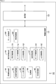
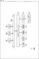
- FIG. 2 is a block diagram showing an example of a main configuration of a base station 102, which is an aspect of an information processing apparatus to which the present technology is applied.
- the base station 102 has an information processing unit 131 and a communication unit 132.
- Information processing department 131 performs various information processing related to patrol support by police officer 113.
- the information processing unit 131 communicates with another device (for example, patrol car 101, flying object 103, terminal device 104, central control server 105, etc.) via the communication unit 132, and acquires information from the other device. Or you can supply the information you generate to other devices.
- the information processing unit 131 can specify a target moving body (a moving body that is the subject of the activity to be supported) and set a monitoring target area (also referred to as a safe zone). Further, the information processing unit 131 can detect (occurrence) a predetermined event in the safe zone.
- the information processing unit 131 can perform processing related to control of other devices such as the patrol car 101, the flying object 103, and the terminal device 104. Further, the information processing unit 131 can perform processing in cooperation with the central control server 105, such as distribution of captured images.
- the configuration of the information processing unit 131 is arbitrary.
- the information processing unit 131 may have the information acquisition unit 141.
- the information acquisition unit 141 performs processing related to information acquisition.
- the information acquisition unit 141 can acquire information supplied from another device (for example, patrol car 101, flying object 103, terminal device 104, central control server 105, etc.) via the communication unit 132. ..
- the information acquisition unit 141 may acquire information (also referred to as sensor information) detected by the sensor of the flying object 103.
- the information acquisition unit 141 may acquire an image captured by the camera 112 as sensor information (also referred to as flight object detection information) from the flight object 103.
- the information acquisition unit 141 may acquire the sensor information (also referred to as terminal detection information) detected by the sensor included in the terminal device 104. Further, the information acquisition unit 141 may acquire information (for example, control information) supplied from the central control server 105. In addition, the information acquisition unit 141 may acquire information (also referred to as vehicle information) regarding the vehicle (patrol car 101) generated in the patrol car 101.
- the sensor information also referred to as terminal detection information
- the information acquisition unit 141 may acquire information (for example, control information) supplied from the central control server 105.
- the information acquisition unit 141 may acquire information (also referred to as vehicle information) regarding the vehicle (patrol car 101) generated in the patrol car 101.
- the content of this vehicle information is arbitrary as long as it is related to the vehicle.
- the vehicle information may include vehicle position / attitude information which is information on the position and attitude of the vehicle.
- the content of this vehicle position / attitude information is arbitrary as long as it relates to the position and attitude of the vehicle.
- the vehicle position / attitude information may include information indicating the position of the patrol car 101, which is positioned by receiving a signal transmitted from a GPS (Global Positioning System) satellite or the like. Further, the vehicle position / attitude information may include information indicating the position and orientation (posture) of the patrol car 101 measured by using an angular velocity sensor (also referred to as a gyroscope or a gyro sensor). Further, the vehicle position / attitude information may include information indicating the position and orientation (posture) of the patrol car 101, which is derived based on the operation (driving operation) of the accelerator, brake, steering, and the like.
- GPS Global Positioning System
- the vehicle information may include vehicle operation information which is information on operations on the vehicle (operations on equipment as a vehicle).
- vehicle operation information is arbitrary as long as it relates to the operation of the vehicle.
- the vehicle operation information indicates the state of the engine of the patrol car 101 (that is, whether or not the engine is running, etc.) (or the state of the ignition key (engine key) (ON / OFF / ACC (accessory power supply)). ) Etc.) may be included.
- the vehicle operation information may include information indicating an open / closed state of the door of the patrol car 101.
- the vehicle information may include vehicle accessory equipment information which is information regarding vehicle accessory equipment.
- vehicle accessory equipment information is information regarding vehicle accessory equipment.
- the content of this vehicle accessory information is arbitrary as long as it relates to the vehicle accessory.
- the vehicle accessory equipment information may include information on the equipment installed in the patrol car 101.
- the equipment may be ancillary equipment as a police vehicle. That is, the vehicle accessory equipment information may include information (police equipment information) regarding the accessory equipment as the police vehicle.
- the vehicle accessory equipment information includes information indicating the state (lighting / extinguishing, etc.) of the rotating light (red light or light bar) of the patrol car 101 (or information indicating the operating status of the operation unit of the rotating light). May be good.
- the information on the equipment attached to the vehicle indicates the usage status (whether it is not used, in use, or recently used, etc.) of the siren or loudspeaker of the patrol car 101 (or the operation of the operation unit of the siren or loudspeaker). Information indicating the situation) may be included.
- the vehicle accessory equipment information indicates the usage status (whether not used, in use, or recently used, etc.) of the wireless communication device of the patrol car 101 (or the operation status of the operation unit of the wireless communication device). Information to be shown) may be included.
- the vehicle accessory equipment information may include information indicating the usage status of equipment that can be attached to and detached from the patrol car 101 (whether or not it has been taken out from the patrol car 101, etc.). For example, it detects the usage status (whether or not it has been removed from the predetermined position, etc.) of weapons (guns, batons, etc.) and tools (flashlights, signs, etc.) installed at a predetermined position (for example, trunk room, etc.) of the patrol car 101. The detection result may be included in the vehicle accessory equipment information.
- the information processing unit 131 may have the target person tracking unit 142.
- the target person tracking unit 142 performs processing related to tracking of the target moving object by the flying object 103.
- the target person tracking unit 142 can identify the police officer 113 on board the patrol car 101 as a target moving object (also referred to as a target person in this case) based on the information acquired by the information acquisition unit 141.
- a process for the target person tracking unit 142 to track the police officer 113 identified as the target person by the flying object 103 based on the information acquired by the information acquisition unit 141 for example, image processing or the processing of the flying object 103). (Generation of movement instruction, etc.) may be performed.
- the information acquired by the information acquisition unit 141 used in the processing related to the tracking of the target moving object may be any information.
- the target person tracking unit 142 may perform those processes based on the flying object detection information, or may perform those processes based on the terminal detection information.
- the content of the information is arbitrary.
- the target person tracking unit 142 may perform those processes based on the position information of the terminal device 104. Further, the subject tracking unit 142 may perform the processing using the identification information of the police officer 113. Further, the subject tracking unit 142 may perform the processing based on the images around the police officer 113 including the police officer 113. Further, the subject tracking unit 142 may perform the processing based on a plurality of information among them.
- the subject tracking unit 142 moves the flying object 103 to the vicinity of the patrol car 101 corresponding to the flying object 103, and tracks the patrol car 101. It may be a target. Further, when the protection target is designated, the target person tracking unit 142 may move the flying object 103 to the vicinity of the designated protection target and set the protection target as the tracking target.
- the information processing unit 131 may have a zone setting unit 143.
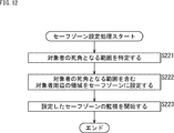
- the zone setting unit 143 performs processing related to the setting of the safe zone.
- the zone setting unit 143 uses the target moving object as a reference, which can detect predetermined information by the flying object 103 (camera 112) based on the target moving object-related information about the target moving object acquired by the information acquisition unit 141.
- a predetermined area at a predetermined relative position can be set as a safe zone (monitored area).
- the zone setting unit 143 may set the area around the police officer 113, which is the target moving object, in a predetermined direction as a safe zone.
- the zone setting unit 143 may set the safe zone so as to include the area behind the police officer 113.
- the zone setting unit 143 may specify a range to be a blind spot of the police officer 113 in the area around the police officer 113, and set the area including the specified range as a safe zone.
- the zone setting unit 143 may set the area behind the police officer 113 as a blind spot of the police officer 113 and set the safe zone so as to include the area behind the police officer 113.
- the zone setting unit 143 may set a safe zone based on, for example, the flying object detection information detected by the flying object 103.
- the sensor information detected by the flying object 103 may be any information. For example, it may be information related to the target moving object (police officer 113).
- the target moving object-related information may be any information as long as it is related to the target moving body, for example, an image, a sound, a temperature distribution, or an image, a sound, a temperature distribution, or an image around the police officer 113 including the target moving body. It may include at least one of the distances. That is, the target moving object-related information may be information about the target moving body itself (for example, the position of the target moving body, the orientation of the face, etc.), information on the area around the target moving body, or the information thereof. It may be both. Further, the target moving object-related information may include other information as well.
- the zone setting unit 143 sets a safe zone based on, for example, the flying object detection information (for example, target moving object related information) detected by the flying object 103 and the terminal detection information detected by the terminal device 104. You may.
- This flying object detection information may be any information.
- the flying object detection information target moving object-related information
- the terminal detection information may be any information.
- the terminal detection information relates to the image or sound of the police officer 113, which is the target moving object, in the field of view, the image or sound of the police officer 113, the biometric information of the police officer 113, or the position, orientation, or posture of the police officer 113. It may include at least one of the information.
- the zone setting unit 143 may set an area in a predetermined range including the patrol car 101 as a safe zone. Further, when the target person tracking unit 142 identifies a predetermined protection target as a tracking target, the zone setting unit 143 may set an area in a predetermined range including the protection target as a safe zone.
- the information processing unit 131 may have a monitoring unit 144.
- the monitoring unit 144 performs processing related to monitoring the safe zone.
- the monitoring unit 144 can detect a predetermined event that occurs in the safe zone set by the zone setting unit 143 based on the information acquired by the information acquisition unit 141.
- the event detected by the monitoring unit 144 is arbitrary.
- the monitoring unit 144 may detect the detection of an invading moving object that has entered the safe zone as an event.
- the monitoring unit 144 may be able to evaluate the detected event.
- the monitoring unit 144 may detect the detection of an invading moving object that has entered the safe zone as an event, and evaluate the importance of the detected event based on the information about the invading moving object.
- Information about this invading object is optional.
- the information about the invading object is at least one of the speed at which the invading object approaches the target object, the components of the invading object, the movement of the invading object, and the known assessment of the invading object. May be included.
- the importance of the event may be determined in consideration of, for example, the degree of danger and the urgency.
- the information processing unit 131 may have a coping processing unit 145.
- the coping processing unit 145 performs processing corresponding to the event.
- the coping processing unit 145 can perform processing according to the event detected by the monitoring unit 144.
- the coping processing unit 145 may perform processing related to notification of the occurrence of an event for the target moving object (for example, notification of invasion of the safe zone by a suspicious person to police officer 113).
- the coping processing unit 145 may cause the flying object 103, the terminal device 104, or both of them to notify the notification.
- the information processing unit 131 may have an air vehicle control unit 146.
- the flight object control unit 146 performs processing related to control of the flight object 103.
- the flight object control unit 146 controls the flight object 103 by generating control information for controlling the flight object 103 and supplying the control information to the flight object 103 via the communication unit 132.
- the flight control unit 146 may have the flight control unit 151.
- the flight control unit 151 controls the flight of the flying object 103.
- the flight control unit 151 generates control information (also referred to as flight control information) regarding the flight (for example, position, altitude, attitude, etc.) of the flying object 103, and the flight control information is flown via the communication unit 132.
- control information also referred to as flight control information
- the flight control information for example, position, altitude, attitude, etc.
- the flying object control unit 146 may have the sensor control unit 152.
- the sensor control unit 152 controls the drive of the sensor of the flying object 103.
- the sensor control unit 152 generates control information (also referred to as sensor control information) that controls the drive of the sensor of the flying object 103 (for example, imaging of the subject by the camera 112), and the sensor control information is used as the communication unit.
- control information also referred to as sensor control information
- the sensor control information controls the drive of the sensor of the flying object 103 (for example, imaging of the subject by the camera 112)
- the flight object control unit 146 may have an output control unit 153.
- the output control unit 153 controls the drive of the output unit (for example, monitor, projector, light emitting unit, speaker, etc.) of the flying object 103.
- the output control unit 153 controls control information (output control information, for example, image display by a monitor, image projection by a projector, light emission of a light emitting unit, audio output by a speaker, etc.) of the flying object 103. (Also referred to as) is generated, and the output control information thereof is supplied to the flying object 103 via the communication unit 132 to control the output of the information by the flying object 103 (for example, notification to the police officer 113).
- the information processing unit 131 may have a terminal control unit 147.
- the terminal control unit 147 performs processing related to the control of the terminal device 104.
- the terminal control unit 147 controls the terminal device 104 by generating control information for controlling the terminal device 104 and supplying the control information to the terminal device 104 via the communication unit 132.
- the terminal control unit 147 may include the sensor control unit 161.
- the sensor control unit 161 controls the drive of the sensor included in the terminal device 104.
- the sensor control unit 161 generates control information (also referred to as sensor control information) that controls the drive of the sensor of the terminal device 104 (for example, imaging of a subject by an image sensor), and uses the sensor control information as a communication unit.
- control information also referred to as sensor control information
- the sensor control information controls the drive of the sensor of the terminal device 104 (for example, imaging of a subject by an image sensor)
- the sensor control information for example, imaging of a subject by an image sensor
- the terminal control unit 147 may have an output control unit 162.
- the output control unit 162 controls the drive of the output unit (for example, a monitor, a projector, a light emitting unit, a speaker, a vibrator, etc.) of the terminal device 104.
- the output control unit 162 controls control information for controlling the drive of the output unit (for example, image display by a monitor, image projection by a projector, light emission of a light emitting unit, audio output by a speaker, vibration by a vibrator, etc.) of the terminal device 104.
- output control information is generated, and the output control information is supplied to the air vehicle 103 via the communication unit 132 to output information by the terminal device 104 (for example, notification to police officer 113). Control.
- the information processing unit 131 may have a server processing unit 148.
- the server processing unit 148 performs processing in cooperation with the central control server 105.
- the server processing unit 148 can perform processing based on the control information transmitted from the central control server 105 and acquired by the information acquisition unit 141.
- This process is optional.
- it may be a process related to control of the flying object 103 or the terminal device 104.
- the server processing unit 148 can also perform processing related to transmission of images and sounds to the central control server 105.
- the server processing unit 148 may transmit the captured image and voice data generated by the flying object 103 and the terminal device 104 to the central control server 105 via the communication unit 132. Further, the server processing unit 148 may cooperate with the central control server 105 to transmit the image or sound by a streaming method.
- the information processing unit 131 may have a vehicle control unit 149.
- the vehicle control unit 149 performs processing related to control of the patrol car 101, which is a vehicle.
- the vehicle control unit 149 controls the patrol car 101 by generating control information for controlling the patrol car 101 and supplying the control information to the patrol car 101 via the communication unit 132.
- the vehicle control unit 149 can move the patrol car 101 or drive the equipment of the patrol car 101 by this control.
- the communication unit 132 has a communication interface and communicates with another device via the communication interface.
- This communication method (standard) is arbitrary, and may be wireless communication, wired communication, or both.
- the communication unit 132 communicates with the patrol car 101, the flying object 103, the terminal device 104, the central control server 105, etc., receives the information transmitted from them, and supplies the information to the information acquisition unit 141. Can be done. Further, the communication unit 132 uses the patrol car 101, the air vehicle 103, and the patrol car 101 to obtain information (for example, control information) supplied from the air vehicle control unit 146, the terminal control unit 147, the server processing unit 148, the vehicle control unit 149, and the like. It can be transmitted to the terminal device 104, the central control server 105, and the like.
- information for example, control information supplied from the air vehicle control unit 146, the terminal control unit 147, the server processing unit 148, the vehicle control unit 149, and the like. It can be transmitted to the terminal device 104, the central control server 105, and the like.
- each processing unit (information acquisition unit 141 to vehicle control unit 149) of the information processing unit 131 can have an arbitrary configuration.
- each of these processing units may be configured by a logic circuit that realizes the above processing.
- each of these processing units may have, for example, a CPU, ROM, RAM, etc., and execute a program using them to realize the above-mentioned processing.
- each of these processing units may have both configurations, and a part of the above-mentioned processing may be realized by a logic circuit, and the other may be realized by executing a program.
- the communication unit 132 can have an arbitrary configuration in addition to the above-mentioned communication interface.
- the communication unit 132 may have a logic circuit that realizes a control process for controlling the above-mentioned communication interface.
- the communication unit 132 may have, for example, a CPU, ROM, RAM, etc., and execute a program using them to realize the control process.
- the communication unit 132 may have both configurations, a part of the control process may be realized by a logic circuit, and the other may be realized by executing a program.
- the configurations of the processing units (information acquisition unit 141 to vehicle control unit 149) of the information processing unit 131 may be independent of each other.
- some processing units realize processing by a logic circuit, and other processing units may be used.
- the processing may be realized by some processing units executing the program, and the other processing units may realize the processing by both the logic circuit and the execution of the program.
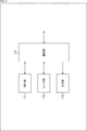
- FIG. 3 is a block diagram showing an example of a main configuration of a flying object 103, which is an aspect of an imaging device (or a moving object) to which the present technology is applied.
- the flying object 103 has a flight unit 171, a sensor unit 172, an output unit 173, and a communication unit 174.
- the flight unit 171 has a configuration related to the flight of the flying object 103, and performs processing related to the flight of the flying object 103.
- the configuration for this flight is optional.
- the flight configuration may include propellers and motors.
- the flight-related configuration may include a control unit or the like that controls them.
- the flight unit 171 may have a configuration for acquiring information from the configuration related to this flight.
- the information obtained from this flight configuration is optional.
- information related to flight such as the position, attitude (direction, inclination, etc.), speed, and rotation speed of the propeller of the flying object 103 may be included.
- information about the periphery of the flying object 103 such as the temperature and the wind speed may be included.
- the configuration for acquiring this information is arbitrary.
- a configuration for acquiring flight information such as a positioning unit that positions the position of the flying object 103 using a GPS signal, a gyro sensor that detects the attitude and speed, and a sensor that detects the rotation speed of the propeller is included. You may. Further, a configuration for acquiring information about the periphery of the flying object 103, such as a temperature sensor and a wind speed sensor, may be included. Further, a control unit for controlling those sensors and the like may be included.
- the flight unit 171 can acquire flight control information (flight control information transmitted from the base station 102) supplied via the communication unit 174.
- the flight unit 171 can drive the configuration related to flight according to the acquired flight control information and fly the flight body 103.
- the flight unit 171 can generate information on flight, information on the periphery of the flying object 103, and the like by using the configuration for acquiring the above-mentioned information.
- the flight unit 171 can transmit the information to other devices (for example, the base station 102, the terminal device 104, the central control server 105, etc.) via the communication unit 174.
- the sensor unit 172 has a configuration related to information detection, and performs processing related to information detection.
- the sensor unit 172 may have a sensor. This sensor may detect any information.
- this sensor may be an image sensor, a microphone, a temperature sensor, a humidity sensor, a distance sensor, a brightness sensor, an invisible light sensor such as infrared rays, or a sensor other than these.
- each sensor may have a plurality of sensors. Further, the sensor unit 172 may have a plurality of types of sensors that detect information different from each other, such as an image sensor and a microphone. Of course, the sensor unit 172 may have a plurality of sensors of a plurality of types, such as two image sensors, three temperature sensors, and four microphones. Further, one sensor may be able to detect a plurality of types of information.
- the sensor unit 172 may have a control unit that controls the above-mentioned sensor. Further, the sensor unit 172 may also have a processing unit that processes the information detected by the above-mentioned sensor.
- the sensor unit 172 can drive the sensor based on the sensor control information supplied via the communication unit 174 to detect the flying object detection information (for example, the target moving object related information). For example, the sensor unit 172 sets parameters related to imaging (exposure, timing, shutter speed, imaging position, imaging direction, angle of view, image processing, etc.) based on sensor control information, and performs imaging using an image sensor. , Capturing images can be generated.
- the flight object detection information may be any information as long as it is the information detected by the sensor included in the sensor unit 172.
- the flight object detection information may be an image, a voice, a temperature distribution, a distance, or a combination of two or more of them. It may be a combination of one or more of these information and information other than these, or it may be only information other than these.
- the sensor unit 172 can transmit the detected information as the flying object detection information to another device (for example, the base station 102 or the like) via the communication unit 174. Further, the sensor unit 172 can analyze the detected information by a predetermined method and transmit the analysis result as the flying object detection information to another device via the communication unit 174.
- the output unit 173 has a configuration related to information output, and performs processing related to information output.
- the output unit 173 may have an output device.
- This output device may be capable of outputting arbitrary information.
- the output device may be a device that outputs information (also referred to as visual information) obtained from vision such as an image or light.
- the device that outputs this visual information may be any.
- it may be a display that displays an image (for example, an LCD (Liquid Crystal Display)), a projector that projects an image, or a light emitting body that emits light (for example, an LED (Light Emitting Diode)). It may be.
- an LCD Liquid Crystal Display
- a projector that projects an image
- a light emitting body that emits light (for example, an LED (Light Emitting Diode)). It may be.
- the output device may be a device that outputs information (also referred to as auditory information) obtained from hearing such as voice. Any device may be used to output this auditory information. For example, it may be a speaker that outputs sound. Of course, the output device may be a device that outputs information other than these.
- the output unit 173 may have a plurality of output devices. Further, the output unit 173 may have a plurality of types of output devices that output different types of information, such as a display and a speaker. Of course, the output unit 173 may have a plurality of output devices of a plurality of types, such as two displays, three projectors, and four speakers. Further, one output device may be able to output a plurality of types of information.
- the output unit 173 may also have a control unit or the like that controls the output device. Further, the output unit 173 may also have a processing unit that generates information output by the output device.
- the output unit 173 can drive the output device based on the output control information supplied via the communication unit 174, and output the information supplied via the communication unit 174, for example.
- the communication unit 174 has a communication interface and communicates with other devices via the communication interface.
- This communication method (standard) is arbitrary, and may be wireless communication, wired communication, or both.
- the communication unit 174 communicates with another device (for example, the base station 102), receives information transmitted from the other device, and supplies the control information to the flight unit 171, the sensor unit 172, or the output unit 173. can do. Further, the communication unit 174 can transmit the information supplied from the flight unit 171, the sensor unit 172, or the output unit 173 to another device (for example, the base station 102).
- each processing unit of the flight unit 171 to the communication unit 174 may have a predetermined logic circuit, and the above-mentioned processing may be realized by using the logic circuit. Further, each processing unit may have, for example, a CPU, ROM, RAM, etc., and execute a program using them to realize the above-mentioned processing. Of course, each processing unit may have both configurations, and a part of the above-mentioned processing may be realized by a logic circuit, and the other may be realized by executing a program.
- each processing unit may be independent of each other. For example, some processing units realize processing by a logic circuit, and some other processing units realize processing by executing a program. In addition, another processing unit may realize the processing by both the logic circuit and the execution of the program.
- FIG. 4 is a block diagram showing an example of a main configuration of a terminal device 104, which is an aspect of an information processing device to which the present technology is applied.
- the terminal device 104 has a sensor unit 181, an output unit 182, and a communication unit 183.
- the sensor unit 181 has a configuration related to information detection, and performs processing related to information detection.
- the sensor unit 181 may have a sensor.
- This sensor may detect any information.
- this sensor may be a sensor such as an image sensor or a microphone that detects a state around the terminal device 104.
- this sensor may be a biosensor that detects biometric information of a person (for example, police officer 113) who carries the terminal device 104, such as heart rate, pulse, and line-of-sight direction.
- this sensor is a sensor that detects the position, orientation, posture, movement, etc.
- the terminal device 104 or a person carrying the terminal device 104 (for example, a police officer 113)), such as a gyro sensor or a GPS receiver.
- a gyro sensor or a GPS receiver.
- sensors other than these may be used.
- the specifications of each sensor are arbitrary.
- the sensor unit 181 may have a plurality of sensors. Further, the sensor unit 181 may have a plurality of types of sensors that detect information different from each other, such as an image sensor and a microphone. Of course, the sensor unit 181 may have a plurality of sensors of a plurality of types, such as two image sensors, three temperature sensors, and four microphones. Further, one sensor may be able to detect a plurality of types of information.
- the sensor unit 181 may have a control unit that controls the above-mentioned sensor. Further, the sensor unit 181 may also have a processing unit that processes the information detected by the above-mentioned sensor.
- the sensor unit 181 can drive the sensor and detect the information based on the sensor control information supplied via the communication unit 183.
- the sensor unit 181 sets parameters related to imaging (exposure, timing, shutter speed, imaging position, imaging direction, angle of view, image processing, etc.) based on sensor control information, and performs imaging using an image sensor. , Capturing images can be generated.
- This information is arbitrary, and may be any information as long as it is the information detected by the sensor included in the sensor unit 181.
- it may be an image, may be voice, may be biometric information of a person carrying the terminal device 104 (for example, police officer 113), or may be the terminal device 104 (or the terminal device 104). It may be the position, orientation, posture, movement, etc. of the person carrying it (for example, police officer 113), it may be a combination of two or more of these, or one or more of these. It may be a combination of information and information other than these, or may be only information other than these.
- the sensor unit 181 can transmit the detected information as terminal detection information to another device (for example, the base station 102 or the like) via the communication unit 183. Further, the sensor unit 181 can analyze the detected information by a predetermined method and transmit the analysis result as terminal detection information to another device via the communication unit 183.
- the output unit 182 has a configuration related to information output, and performs processing related to information output.
- the output unit 182 may have an output device.
- This output device may be capable of outputting arbitrary information.
- the output device may be a device that outputs visual information. Any device may be used to output this visual information.
- it may be a display that displays an image (for example, an LCD (Liquid Crystal Display)), a projector that projects an image, or a light emitting body that emits light (for example, an LED (Light Emitting Diode)).
- the output device may be a device that outputs auditory information. Any device may be used to output this auditory information.
- it may be a speaker that outputs sound.
- the output device may be a device that vibrates itself and outputs information by using the strength, length, period, on / off timing, etc. of the vibration. Any device that outputs information by this vibration may be used. For example, it may be a vibrator. Of course, the output device may be a device that outputs information other than these.
- the output unit 182 may have a plurality of output devices. Further, the output unit 182 may have a plurality of types of output devices that output different types of information, such as a display and a speaker. Of course, the output unit 173 may have a plurality of output devices of a plurality of types, such as two displays, three projectors, and four speakers. Further, one output device may be able to output a plurality of types of information.
- the output unit 182 may also have a control unit or the like that controls the output device. Further, the output unit 182 may also have a processing unit that generates information output by the output device.
- the output unit 182 can drive the output device based on the output control information supplied via the communication unit 183, and output the information supplied via the communication unit 183, for example.
- the communication unit 183 has a communication interface, and communicates with another device via the communication interface.
- This communication method (standard) is arbitrary, and may be wireless communication, wired communication, or both.
- the communication unit 183 can communicate with another device (for example, the base station 102), receive information transmitted from the other device, and supply the control information to the sensor unit 181 or the output unit 182. Further, the communication unit 183 can transmit the information supplied from the sensor unit 181 or the output unit 182 to another device (for example, the base station 102). Further, the communication unit 183 stores information (referred to as terminal information) related to the terminal device 104 in advance, such as identification information of the terminal device 104, and transmits the terminal information to another device (for example, the base station 102). can do.
- another device for example, the base station 102
- the communication unit 183 stores information (referred to as terminal information) related to the terminal device 104 in advance, such as identification information of the terminal device 104, and transmits the terminal information to another device (for example, the base station 102). can do.
- each processing unit of the sensor unit 181 to the communication unit 183 may have a predetermined logic circuit, and the above-mentioned processing may be realized by using the logic circuit. Further, each processing unit may have, for example, a CPU, ROM, RAM, etc., and execute a program using them to realize the above-mentioned processing. Of course, each processing unit may have both configurations, and a part of the above-mentioned processing may be realized by a logic circuit, and the other may be realized by executing a program.
- each processing unit may be independent of each other. For example, some processing units realize processing by a logic circuit, and some other processing units realize processing by executing a program. In addition, another processing unit may realize the processing by both the logic circuit and the execution of the program.
- FIG. 5 is a block diagram showing an example of a main configuration of a central control server 105, which is an aspect of an information processing apparatus to which the present technology is applied.
- the central control server 105 has an instruction instruction generation unit 191 and a streaming processing unit 192, and a communication unit 193.
- the instruction command generation unit 191 performs processing related to generation of instruction commands for other devices of the patrol support system 100.
- the instruction command generation unit 191 can accept a user (operator) operation for a user interface (not shown) and generate an instruction command based on the user operation or the like. Further, the instruction command generation unit 191 can transmit the generated instruction instruction to another device (for example, the base station 102 or the like) via the communication unit 193.
- Streaming processing unit 192 performs processing related to playback of streaming data.
- the streaming processing unit 192 can receive the streaming data transmitted from another device (for example, the base station 102 or the like) via the communication unit 193, and reproduce and display the received streaming data.
- the operator can view the captured image to be streamed.
- the operator can more easily grasp the situation around the patrol car 101 and the police officer 113. Therefore, more appropriate instructions can be given depending on the situation.
- the communication unit 193 has a communication interface and communicates with other devices via the communication interface.
- This communication method (standard) is arbitrary, and may be wireless communication, wired communication, or both.
- the communication unit 193 can acquire the instruction command supplied from the instruction command generation unit 191 and transmit it to another device (for example, the base station 102). Further, the communication unit 193 can receive the streaming data transmitted from another device (for example, the base station 102) and supply it to the streaming processing unit 192.
- each processing unit of the instruction command generation unit 191 to the communication unit 193 may have a predetermined logic circuit, and the above-mentioned processing may be realized by using the logic circuit. Further, each processing unit may have, for example, a CPU, ROM, RAM, etc., and execute a program using them to realize the above-mentioned processing. Of course, each processing unit may have both configurations, and a part of the above-mentioned processing may be realized by a logic circuit, and the other may be realized by executing a program.
- each processing unit may be independent of each other. For example, some processing units realize processing by a logic circuit, and some other processing units realize processing by executing a program. In addition, another processing unit may realize the processing by both the logic circuit and the execution of the program.
- Each device has the above configuration, and by performing the above-mentioned processing, it is possible to provide more useful support for the activity of the target moving object.
- the base station 102 of the patrol support system 100 can perform processing related to patrol support (activity support processing) based on the information supplied from the flying object 103 and the terminal device 104.
- An example of the flow of the activity support process executed by the base station 102, the flying object 103, and the terminal device 104 of the patrol support system 100 will be described with reference to the flowchart of FIG.
- step S111 the sensor unit 172 of the flying object 103 detects information using the sensor, and the detected information is used as sensor information (flying object detection information), and the communication unit 174 is used. It is supplied to the base station 102 via.
- step S101 the information acquisition unit 141 of the base station 102 acquires the sensor information (flying object detection information) supplied from the flying object 103 via the communication unit 132.
- step S121 the communication unit 183 of the terminal device 104 supplies the terminal information stored in advance to the base station 102.
- the information acquisition unit 141 of the base station 102 acquires the terminal information supplied from the terminal device 104 via the communication unit 132.
- step S122 the sensor unit 181 of the terminal device 104 detects information using the sensor, and supplies the detected information as sensor information (terminal detection information) to the base station 102 via the communication unit 183. ..
- step S103 the information acquisition unit 141 of the base station 102 acquires the sensor information (terminal detection information) supplied from the terminal device 104 via the communication unit 132.
- step S104 the target person tracking unit 142 to the coping processing unit 145 of the base station 102 performs processing related to the safe zone based on the information acquired in steps S101 to S103.
- step S105 the flight object control unit 146 generates control information (flight control information, sensor control information, output control information, etc.) for controlling the flight object 103 based on the processing result of step S104, and causes the communication unit 132.
- the control information is supplied to the flying object 103 via.
- step S112 the communication unit 174 of the aircraft 103 acquires the control information supplied from the base station 102.
- step S113 the flight unit 171 to the output unit 173 perform output processing related to patrol support based on the control information acquired in step S112.
- step S106 the terminal control unit 147 generates control information (sensor control information, output control information, etc.) for controlling the terminal device 104 based on the processing result of step S104, and controls the control information via the communication unit 132.
- Information is supplied to the terminal device 104.
- step S123 the communication unit 183 of the terminal device 104 acquires the control information supplied from the base station 102.
- step S124 the sensor unit 181 and the output unit 182 perform output processing related to patrol support based on the control information acquired in step S123.
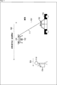
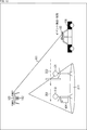
- This police officer 113 carries a terminal device 104. Further, the police officer 113 rides on the patrol car 101, moves, and when it arrives at a desired area, disembarks from the patrol car 101 and patrols the vicinity as shown by the dotted arrow 201. During the patrol, police officer 113 may be at higher risk of being attacked by a thug, for example, than a general person. Therefore, the patrol support system 100 monitors the police officer 113 and its surroundings, detects the occurrence of danger or abnormality, and notifies the police officer 113 or the like, for example, so that the police officer 113 can patrol more safely. To support.
- the patrol support system 100 causes the police officer 113 to be tracked by the flying object 103. Therefore, the target person tracking unit 142 of the base station 102 first controls the flight of the flight object 103 via the flight control unit 151, and takes off the flight object 103 from the base station 102. More specifically, the flight control unit 151 generates control information for taking off the flight object 103 according to the control of the target person tracking unit 142, and transmits the control information to the flight object 103 via the communication unit 132. The flight unit 171 of the flight body 103 acquires the control information via the communication unit 174, drives the flight unit 103 based on the control information, takes off the flight body 103 from the base station 102, and starts the flight.
- the target person tracking unit 142 identifies the police officer 113 who is the target person (target moving object), and tracks the specified police officer 113 by the flying object 103 as shown by the dotted arrow 203.
- the subject tracking unit 142 identifies and identifies the police officer 113 based on the position information of the terminal device 104 carried by the police officer 113 and the image around the police officer 113 including the police officer 113.
- the 113 may be tracked by the flying object 103.
- the police officer 113 can be specified based on the flying object detection information (for example, the target moving object related information regarding the police officer 113) detected by the sensor unit 172 of the flying object 103.
- This flight object detection information may be any information as long as it is detected by the sensor unit 172.
- the police officer 113 may be specified based on the image captured by the police officer 113 captured by the sensor unit 172. That is, the captured image of the police officer 113 or the like may be used as the target moving object-related information.
- the target person tracking unit 142 of the base station 102 controls the sensor unit 172 of the flying object 103 via the sensor control unit 152, and images the police officer 113 using an image sensor or the like (for example, a camera 112). Let me. Then, the target person tracking unit 142 of the base station 102 acquires the captured image (target moving object-related information) from the flying object 103 via the information acquisition unit 141, analyzes the image, and performs the uniform and identification card of the police officer 113. , Or a badge or the like is recognized, and the police officer 113 is specified based on the recognition result.
- the police officer 113 may be specified based on the voice of the police officer 113 recorded by the sensor unit 172. That is, the voice of the police officer 113 or the like may be used as the target moving object-related information.
- the target person tracking unit 142 of the base station 102 controls the sensor unit 172 of the flying object 103 via the sensor control unit 152, and makes the voice of the police officer 113 recorded by using a microphone or the like. Then, the target person tracking unit 142 of the base station 102 acquires the voice data (voice of the police officer 113) from the flying object 103 as the target moving object-related information via the information acquisition unit 141, analyzes the voice, and performs the voice analysis to the police officer.
- the voice of 113 is recognized, and the police officer 113 is identified based on the recognition result.
- the police officer 113 can be specified based on the sensor information (terminal detection information) detected by the sensor unit 181 of the terminal device 104.
- This terminal detection information may be any information as long as it is detected by the sensor unit 181.
- the police officer 113 may be specified based on the image captured by the police officer 113 captured by the sensor unit 181. That is, the captured image of the police officer 113 may be used as the terminal detection image.
- the target person tracking unit 142 of the base station 102 controls the sensor unit 181 of the terminal device 104 via the sensor control unit 161 and causes the police officer 113 to take an image using an image sensor or the like. Then, the target person tracking unit 142 of the base station 102 acquires an image (terminal detection information) of the police officer 113 from the terminal device 104 via the information acquisition unit 141, analyzes the image, and uniforms the police officer 113. , Identification card, badge, etc., and identify police officer 113 based on the recognition result.
- the police officer 113 may be specified based on the voice of the police officer 113 recorded by the sensor unit 181. That is, the captured image of the police officer 113 may be used as the terminal detection information.
- the target person tracking unit 142 of the base station 102 controls the sensor unit 181 of the terminal device 104 via the sensor control unit 161 to record the voice of the police officer 113 using a microphone or the like. Then, the target person tracking unit 142 of the base station 102 acquires the voice data (voice of the police officer 113) from the terminal device 104 as terminal detection information via the information acquisition unit 141, analyzes the voice, and performs the voice analysis to the police officer 113.
- the police officer 113 is identified based on the recognition result.
- the police officer 113 may be specified based on the position of the terminal device 104 (police officer 113) detected by the sensor unit 181. That is, the position information of the police officer 113 may be used as the terminal detection information.
- the target person tracking unit 142 of the base station 102 controls the sensor unit 181 of the terminal device 104 via the sensor control unit 161 and uses a gyro sensor, a GPS receiver, or the like to control the terminal device 104 (police officer). 113) The position and the like are detected.
- the target person tracking unit 142 of the base station 102 acquires the position data (position of the terminal device 104, etc.) from the terminal device 104 as terminal detection information via the information acquisition unit 141, analyzes it, and police officer 113.
- the position of the police officer 113 is recognized, and the police officer 113 is specified based on the recognition result.
- the subject tracking unit 142 can more easily identify the subject using a general sensor (without the need for a special sensor). Therefore, the increase in cost can be suppressed (the target person can be identified at a lower cost).
- the police officer 113 can be specified based on the terminal information of the terminal device 104.
- This terminal information may be any information as long as it can identify the terminal device 104.
- the police officer 113 may be specified based on the terminal information of the terminal device 104 carried by the police officer 113.
- the target person tracking unit 142 of the base station 102 acquires the terminal information from the terminal device 104 via the information acquisition unit 141, and identifies the police officer 113 based on the terminal information.
- the target person tracking unit 142 can more easily identify the target person by using the identification information of the terminal device carried by the police officer 113. Therefore, the increase in cost can be suppressed (the target person can be identified at a lower cost).
- the method of specifying the police officer 113 is arbitrary and is not limited to the above example. For example, a plurality of methods in the above-mentioned examples may be combined and applied.
- the subject tracking unit 142 may identify the police officer 113 by using a plurality of information in the above-mentioned example. Further, any method in the above-mentioned examples may be applied in combination with another method not described above.
- the subject tracking unit 142 may identify the police officer 113 by using any of the information in the above-mentioned example and other information not described above.
- the target person tracking unit 142 causes the flying object 103 to track the specified target person.
- the flight control unit 151 of the flight body control unit 146 generates flight control information based on the instruction and transmits the flight control information to the flight body 103 to control the flight of the flight body 103 and control the flight of the flight body 103.
- the aircraft body 103 flies under its control and flies over the identified police officer 113.
- the subject tracking unit 142 When the tracking is started, the subject tracking unit 142 repeatedly or continuously identifies the police officer 113 as described above, updates the position of the identified police officer 113, and changes the flying object 103 to the police officer 113. Track to the latest position.
- the target person tracking unit 142 executes the tracking process as the process of step S104 of FIG. An example of the flow of the tracking process will be described with reference to the flowchart of FIG.
- the subject tracking unit 142 receives, for example, sensor information (flying object detection information or terminal detection) from the flying object 103, the terminal device 104, or both via the information acquisition unit 141. Information) and terminal information, etc., which are necessary for identifying police officer 113.
- the target person tracking unit 142 identifies the target person (police officer 113) to be tracked based on the acquired information (sensor information, terminal information, or both).
- step S202 the subject tracking unit 142 controls the flying object 103 via the flight control unit 151, and the specified police officer 113 is tracked.
- the flight unit 171 of the flight body 103 is driven according to the control thereof, and causes the flight body 103 to fly so as to track the police officer 113.
- step S203 the target person tracking unit 142 determines whether or not to end the tracking, and waits until it is determined that the tracking is completed. For example, when it is determined that the tracking is finished when a predetermined condition is satisfied or an instruction is given, the target person tracking unit 142 ends the tracking process.
- the subject tracking unit 142 can more easily identify the police officer 113 and track the specified police officer 113.
- the zone setting unit 143 of the base station 102 sets the safe zone 211, which is the monitoring target area by the monitoring unit 144, as shown in FIG. At that time, the zone setting unit 143 sets the safe zone 211 based on the target moving object-related information regarding the police officer 113 detected by the flying object 103 (sensor unit 172).
- the zone setting unit 143 provides information related to the target moving object detected by the sensor unit 172 (for example, information such as an image, sound, temperature distribution, or distance around the police officer 113 including the police officer 113 (among these).
- the safe zone 211 may be set based on (including at least one of)).
- the flying object 103 Since the flying object 103 is movable, it is possible to detect information around the police officer 113 (information related to the target moving object) from an arbitrary position. Therefore, it is possible to detect the target moving object-related information at a more suitable position, such as a position where more accurate information can be obtained. Therefore, by using the target moving object-related information detected by the sensor unit 172 of the flying object 103, the zone setting unit 143 can set the safe zone 211 based on more accurate information. That is, the zone setting unit 143 can set the safe zone 211 more accurately. Further, since the monitoring unit 144 can more accurately identify the set range of the safe zone 211, the monitoring unit 144 suppresses a decrease in the monitoring accuracy of the safe zone 211 (more typically, the accuracy is improved). be able to.
- the safe zone 211 may be any region as long as the predetermined information can be detected by the flying object 103 (sensor unit 172).
- the shape of the safe zone 211 is arbitrary.
- the safe zone 211 may be a two-dimensional region or a three-dimensional region.
- the zone setting unit 143 may set a two-dimensional area of a predetermined range on the ground as a safe zone 211.
- the shape of the safe zone 211 may be any shape as long as it is a two-dimensional shape, for example, it may be circular, rectangular, or any other shape. May be good.
- the zone setting unit 143 may set a three-dimensional area in a predetermined range of space as a safe zone 211.
- the shape of the safe zone 211 may be any shape as long as it is a three-dimensional shape, for example, it may be conical as shown in FIG. 9, or it may be a rectangular parallelepiped. Other shapes may be used.
- the size of the safe zone 211 is arbitrary.
- the range of the safe zone 211 may be wider or narrower than the detectable range of the sensor included in the sensor unit 172 of the flying object 103.
- the flying object 103 may be moved or the image sensor may be imaged. By changing the posture and imaging the safe zone 211 a plurality of times, the entire area of the safe zone 211 may be imaged.
- the zone setting unit 143 may set the safe zone 211 by using the depth information around the police officer 113. That is, this depth information may be included in the target moving object related information.
- the method of deriving this depth information is arbitrary.
- the flight control unit 151 moves the flying object 103
- the sensor control unit 152 causes the sensor unit 172 to image the periphery of the police officer 113 at a plurality of angles, and the parallax of the captured images is used to derive depth information. You may let it.
- the sensor unit 172 may use a plurality of cameras to image the periphery of the police officer 113, and use the parallax of the captured images to derive the depth information.
- the sensor unit 172 may derive the depth information by using a distance sensor or the like. Of course, this depth information may be derived by any processing unit other than the sensor unit 172.
- the zone setting unit 143 can set the safe zone 211 more accurately. Further, since the monitoring unit 144 can more accurately identify the set range of the safe zone 211, the monitoring unit 144 suppresses a decrease in the monitoring accuracy of the safe zone 211 (more typically, the accuracy is improved). be able to.
- the zone setting unit 143 sets the safe zone 211 based on the terminal detection information detected by the terminal device 104 (sensor unit 181) carried by the police officer 113 in addition to the target moving object related information. You may do it.
- the terminal detection information includes an image or sound of the police officer 113 in the field of view detected by the sensor unit 181, an image or sound of the police officer 113, biometric information of the police officer 113, or the position and orientation of the police officer 113.
- it may include information about the posture (including at least one of these). That is, the safe zone 211 may be set based on this information.
- the zone setting unit 143 can set the safe zone 211 more accurately. Further, since the monitoring unit 144 can more accurately identify the set range of the safe zone 211, the monitoring unit 144 suppresses a decrease in the monitoring accuracy of the safe zone 211 (more typically, the accuracy is improved). be able to.
- the zone setting unit 143 When setting such a safe zone 211, for example, the zone setting unit 143 is in a predetermined relative position with respect to the police officer 113 in which predetermined information can be detected by the flying object 103 (camera 112).
- a predetermined area may be set as the safe zone 211.
- the zone setting unit 143 may set the area around the police officer 113 in a predetermined direction as the safe zone 211.
- the zone setting unit 143 may set the safe zone 211 so as to include the area behind the police officer 113.
- the zone setting unit 143 may set an area of a predetermined range including the blind spot of the police officer 113 as the safe zone 211.
- the monitoring unit 144 can monitor the area (for example, the blind spot) where it is difficult for the police officer 113 to guard.
- the area where it is difficult to be alert means, for example, an angle (predetermined direction) that police officers cannot visually see based on the direction of the face or the direction of the eyes, for example, a rear area. Therefore, the coping processing unit 145 can provide more useful information for the police officer 113. That is, the patrol support system 100 can provide more useful support for the activity of the target moving object.
- the zone setting unit 143 may set the area around the police officer 113 in a predetermined direction as the safe zone 211.
- the zone setting unit 143 may specify a range of the area around the police officer 113 that is a blind spot of the police officer 113, and set the area including the specified range as the safe zone 211.
- the zone setting unit 143 specifies the moving direction, face direction, line-of-sight direction, etc. of the police officer 113, identifies the range of the blind spot of the police officer 113 from the information, and divides a part or all of the blind spot.
- the safe zone 211 may be set to include the safe zone 211.
- the moving direction, face direction, line-of-sight direction, etc. of the police officer 113 can be specified based on arbitrary information.
- the zone setting unit 143 may specify based on the image of the police officer 113 captured by the image sensor included in the sensor unit 172 of the flying object 103. Since the flying object 103 is movable, the image sensor included in the sensor unit 172 can image the police officer 113 from an arbitrary position. That is, it is possible to easily realize an image from a position where the face of the police officer 113 can be clearly seen (for example, the front). Therefore, by using the captured image, the zone setting unit 143 can more accurately specify the moving direction, the direction of the face, the direction of the line of sight, and the like of the police officer 113.
- the image sensor included in the sensor unit 172 can more easily realize imaging from a position where the range of the blind spot of the police officer 113 can be more accurately specified. That is, the zone setting unit 143 can more accurately identify the range of the blind spot of the police officer 113 by using this captured image. Therefore, the zone setting unit 143 can more easily realize more accurate setting of the safe zone 211.
- the image sensor of the sensor unit 172 can always take an image from a suitable position even when the moving object police officer 113 is targeted. it can. That is, the zone setting unit 143 can set the safe zone 211 more accurately with respect to the object which is a moving object by using the captured image captured by this image sensor.
- the zone setting unit 143 captures an image of the face and eyes of the police officer 113 and the front direction of the police officer 113 captured by the image sensor of the sensor unit 181 of the terminal device 104 carried by the police officer 113. Or information on the position and posture of the police officer 113 derived by using the gyro sensor or GPS receiver of the sensor unit 181 may be used for identification. By doing so, it is possible to more accurately identify the range of the blind spot of the police officer 113.
- the blind spot of the police officer 113 may include, for example, an area outside the field of view of the police officer 113 (for example, behind the police officer 113).
- the zone setting unit 143 specifies, for example, the movement direction, the direction of the face, the direction of the line of sight, etc. of the police officer 113 as described above, so that the area outside the line of sight of the police officer 113 (that is, the area outside the view of the police officer 113) ) Can be easily identified.
- the zone setting unit 143 may set the safe zone 211 so as to include an area outside the field of view of the police officer 113 thus identified.
- the zone setting unit 143 may set only the area behind the police officer 113 as the safe zone 211 as shown in A of FIG. That is, the zone setting unit 143 may set the safe zone 211 so as not to include the position of the police officer 113. Further, for example, the zone setting unit 143 may set the safe zone 211 so that the position of the police officer 113 and the area behind the police officer 113 are included as shown in B of FIG. In that case, the zone setting unit 143 may set the safe zone 211 so that the area outside the field of view of the police officer 113 is wider than the area within the field of view of the police officer 113. For example, the zone setting unit 143 may set the safe zone 211 so that the area behind the police officer 113 is wider than the area in front of the police officer 113.
- the flying body 103 When the police officer 113 is tracked by the flying body 103, the flying body 103 is positioned in front of the police officer 113 (face or line of sight), and the image sensor of the sensor unit 172 of the flying body 103 causes the police.
- the police officer 113 and its surroundings may be imaged from the front of the officer 113.
- the zone setting unit 143 can more easily set the safe zone 211 so as to include the range that becomes the blind spot of the police officer 113.
- the rear side of the police officer 113 has been used as an example outside the line of sight of the police officer 113, but the blind spot of the police officer 113 is not limited to this, and is, for example, the side of the police officer 113. You may. Further, for example, the range of the blind spot of the police officer 113, where it is difficult for the police officer 113 to detect danger or abnormality, may be set as a safe zone 211, which is wider than the range where it is easy to detect. For example, in general, the side is easier to detect danger or abnormality than the rear. Therefore, the zone setting unit 143 may set the area behind the police officer 113 as the safe zone 211 wider than the area on the side of the police officer 113.
- the blind spot of the police officer 113 may include, for example, an area where the view of the police officer 113 is obstructed by an obstacle or the like.
- the zone setting unit 143 identifies an obstacle (an object that obstructs the view of the police officer 113) around the police officer 113, and from the information thereof and the range of the view of the police officer 113 identified as described above, the police A range that becomes a blind spot of the officer 113 (an area that cannot be seen from the police officer 113 due to the obstacle) may be specified, and the safe zone 211 may be set.
- This obstacle can be identified based on arbitrary information.
- the zone setting unit 143 may identify this obstacle based on an image of the vicinity of the police officer 113 captured by the image sensor included in the sensor unit 172 of the flying object 103. Since the flying object 103 is movable, it is possible to more easily take an image from a position where an obstacle can be more easily identified. That is, by doing so, the zone setting unit 143 can more accurately identify the obstacle.
- the flying object 103 is movable, it is possible to more easily image the range including the area where the view of the police officer 113 is obstructed by the obstacle or the like. For example, it is possible to easily realize that the flying object 103 wraps around behind the obstacle when viewed from the police officer 113 and performs an image pickup. That is, by doing so, the zone setting unit 143 can more accurately identify the area where the view of the police officer 113 is blocked by an obstacle or the like.
- the zone setting unit 143 identifies an obstacle by using an image in the front direction of the police officer 113 captured by the image sensor of the sensor unit 181 of the terminal device 104 carried by the police officer 113. You may try to do it. By doing so, the zone setting unit 143 can more accurately identify an obstacle, or can identify an area where the view of the police officer 113 is obstructed by the obstacle or the like.
- the safe zone 211 may be set so that the zone setting unit 143 includes an area in which the view of the police officer 113 is obstructed by the obstacles identified in this way.
- the zone setting unit 143 can more easily identify the blind spot of the police officer 113.
- the safe zone 211 can be set to include a range (a region where the view of the police officer 113 is obstructed by an obstacle or the like).
- the zone setting unit 143 includes a safe zone 211A including an area behind the police officer 113 and a safe zone including an area where the view of the police officer 113 is obstructed by an obstacle 212.
- 211B may be set. That is, a plurality of safe zones 211 can be set. In that case, the ranges of the safe zones 211 may be set independently of each other. That is, the shape and width of each safe zone 211 are arbitrary and may or may not be unified.
- the zone setting unit 143 includes a safe zone 211A including an area behind the police officer 113 and a safe area including an area where the view of the police officer 113 is obstructed by an obstacle 212.
- One safe zone 211 including both the zone 211B may be set.
- the zone setting unit 143 can more easily set the safe zone 211 based on the information detected by the flying object 103, so that the zone setting unit 143 can have an arbitrary shape, an arbitrary width, an arbitrary position, and an arbitrary position.
- a number of safe zones 211 can be set. Therefore, the zone setting unit 143 can set a more appropriate shape, size, position, and number of safe zones 211 so that it can provide more useful information for the police officer 113. That is, the patrol support system 100 can provide more useful support for the activity of the target moving object.
- Safe zone setting process flow> In order to set the safe zone as described above, the zone setting unit 143 executes the safe zone setting process as the process of step S104 of FIG. An example of the flow of the safe zone setting process will be described with reference to the flowchart of FIG.
- the zone setting unit 143 acquires the target moving object related information and the like from the flying object 103 and the like via the information acquisition unit 141 in step S221 as described above, and uses the information as the information. Based on this, the range of the blind spot of the target person (police officer 113) is specified.
- step S222 as described above, the zone setting unit 143 sets the area around the target person as the safe zone 211, including the range that becomes the blind spot of the target person specified in step S221.
- step S223 the monitoring unit 144 starts monitoring the safe zone 211 set in step S222 (detection of an event occurring in the safe zone 211).
- step S223 When the process of step S223 is completed, the safe zone setting process is completed.
- the zone setting unit 143 can more easily set the safe zone 211.
- the monitoring unit 144 can start monitoring the safe zone 211.
- Event detection / action> When the safe zone 211 is set, the monitoring unit 144 of the base station 102 monitors the safe zone 211 and detects a predetermined event that occurs in the safe zone 211, as shown in FIG. When an event is detected by the monitoring unit 144, the coping processing unit 145 of the base station 102 performs processing corresponding to the detected event.
- the event detection by the monitoring unit 144 can be performed based on arbitrary information.
- the monitoring unit 144 may detect the event based on the sensor information detected by the sensor included in the sensor unit 172 of the flying object 103.
- the monitoring unit 144 uses an image captured by the image sensor of the sensor unit 172 to capture an image of the safe zone 211, a sound recorded by the microphone of the sensor unit 172 near the safe zone 211, or a temperature sensor of the sensor unit 172.
- the event may be detected based on the detected temperature distribution of the safe zone 211 or the like.
- the monitoring unit 144 may detect the event based on the sensor information other than these examples, or may detect the event based on a plurality of types of sensor information. Since the flying object 103 is movable, the sensor unit 172 can detect the information at a position where more accurate information can be detected. Therefore, the monitoring unit 144 can detect the event more accurately by using the sensor information detected by the sensor included in the sensor unit 172.
- the monitoring unit 144 can also detect an event based on information other than the information detected by the sensor unit 172.
- the monitoring unit 144 can also detect an event based on the sensor information detected by the sensor unit 181 of the terminal device 104 possessed by the police officer 113. Further, the monitoring unit 144 can also detect an event by using both the information detected by the sensor unit 172 and the information detected by the sensor unit 181.
- the event to be detected is arbitrary.
- the monitoring unit 144 may detect the detection of an invading moving object that has entered the safe zone 211 as an event.
- the monitoring unit 144 may detect the event based on arbitrary information.
- the monitoring unit 144 may detect an intruding object invading the safe zone 211 based on the captured image of the safe zone 211 captured by the image sensor of the sensor unit 172.
- the monitoring unit 144 may detect the detection of all invading moving objects as an event. Further, for example, the monitoring unit 144 may detect the intrusion of the suspicious person 221 into the safe zone 211 as an event, as indicated by the dotted arrow 222 in FIG. That is, the monitoring unit 144 detects an intruding object that invades the safe zone 211, further determines whether or not the invading object is a suspicious person 221 and detects it as an event if it is a suspicious person 221. You may do so. That is, the monitoring unit 144 may detect the event using a plurality of conditions.
- the monitoring unit 144 can detect a more specific event (detection of intrusion of suspicious person 221 instead of intrusion of intruding moving object). Therefore, the coping processing unit 145 can perform more appropriate processing for the event. That is, the patrol support system 100 can provide more useful support for the activity of the target moving object.
- the method of determining whether or not the invading object is a suspicious person is arbitrary.
- the monitoring unit 144 identifies the shape and movement of the invading object detected from the captured image by image analysis, and attacks the police officer 113 to determine whether or not the person possesses the weapon.
- Whether or not the person is a person for example, whether or not the person is registered in the registration information prepared in advance such as a criminal database, and whether or not the person is a suspicious person 221 based on the judgment result. May be determined.
- the monitoring unit 144 may detect a state change (abnormal occurrence) of the police officer 113 who is the target person as an event.
- the change of state (abnormality occurrence) of the police officer 113 means that the police officer 113 cannot normally patrol, for example, due to injury or mental instability.
- the monitoring unit 144 can detect the event based on arbitrary information.
- the monitoring unit 144 may detect a change of state (abnormality occurrence) of the police officer 113 based on the image captured by the image sensor of the sensor unit 172.
- the monitoring unit 144 changes the state of the police officer 113 based on the biometric information (for example, heartbeat, pulse, exhalation, sweating amount, etc.) of the police officer 113 detected by the biosensor or the like of the sensor unit 181. (Abnormality) may be detected.
- biometric information for example, heartbeat, pulse, exhalation, sweating amount, etc.
- the monitoring unit 144 may be able to detect an event that occurs outside the safe zone 211.
- the monitoring unit 144 may detect a firing sound or an explosion sound generated outside the safe zone 211 as an event based on the voice information detected by the sensor unit 172.
- the sensor unit 172 detects the sound near the safe zone 211 using a plurality of microphones having directivity in different directions, and the monitoring unit 144 generates a firing sound or an explosion sound based on the sound information. It may be detected, and further, the direction of occurrence of the firing sound or the explosion sound may be specified.
- the processing corresponding to the event performed by the coping processing unit 145 is arbitrary.
- the coping processing unit 145 may perform processing related to notification regarding the detected event as the processing.
- the content of the notification regarding this event is optional.
- it may be a notification that an event has occurred.
- information related to the event (supplementary information, etc.) may be presented.
- the subject of this notification is arbitrary.
- the coping processing unit 145 may process the notification to be given to the police officer 113 (target person). It should be noted that this notification may be given to a person other than police officer 113.
- the method of this notification is arbitrary.
- the coping processing unit 145 may perform this notification using visual information such as an image or light. Further, the coping processing unit 145 may perform this notification using auditory information such as voice. Further, the coping processing unit 145 may perform this notification by using vibration or the like.
- the device that gives this notification is arbitrary.
- the flying object 103 may make this notification.
- the coping processing unit 145 controls the output unit 173 of the aircraft 103 via the output control unit 153, and causes the output device to notify the output device.
- the coping processing unit 145 can display an image notifying the occurrence of an event on a display such as an LCD included in the output unit 173.
- the coping processing unit 145 can project an image notifying the occurrence of an event on the projector included in the output unit 173.
- the coping processing unit 145 can cause the light emitting body such as the LED included in the output unit 173 to emit light of a pattern indicating the occurrence of an event.
- the coping processing unit 145 can cause the speaker of the output unit 173 to output a voice notifying the occurrence of an event.
- the flying object 103 may make a notification by a plurality of methods among these. Further, the flying object 103 may make the notification by a method other than the above-mentioned example.
- the terminal device 104 may perform this notification.
- the coping processing unit 145 controls the output unit 182 of the terminal device 104 via the output control unit 162, and causes the output device to notify the output device.
- the coping processing unit 145 can display an image notifying the occurrence of an event on a display such as an LCD included in the output unit 182.
- the coping processing unit 145 can project an image notifying the occurrence of an event on the projector included in the output unit 182.
- the coping processing unit 145 can cause the light emitting body such as the LED included in the output unit 182 to emit light of a pattern indicating the occurrence of an event.
- the coping processing unit 145 can cause the speaker of the output unit 182 to output a voice notifying the occurrence of an event. Further, the coping processing unit 145 can vibrate the vibrator included in the output unit 182 with a pattern indicating the occurrence of an event.
- the terminal device 104 may perform the notification by a plurality of methods among these. Further, the terminal device 104 may perform the notification by a method other than the above-mentioned example.
- this notification may be made on both the flying object 103 and the terminal device 104.
- this notification may be made in a device other than the flying object 103 and the terminal device 104.
- the patrol car 101 or the central control server 105 may make this notification.
- the coping processing unit 145 supplies the information regarding the notification to the device.
- the monitoring unit 144 may evaluate the detected event. For example, the monitoring unit 144 may evaluate the importance of the detected event. The criteria for the importance of this event is arbitrary. For example, the monitoring unit 144 may evaluate the importance of the detected event based on the risk or urgency of the event.
- the method of determining the degree of danger or urgency of this event is arbitrary.
- the monitoring unit 144 may determine the degree of danger or the degree of urgency based on the content of the detected event. For example, when the intrusion of an intruding object into the safe zone 211 is detected as an event as in the above example, the risk or urgency (that is, importance) of the detected event is evaluated based on the information about the invading object. You may do so.
- the content of the information about the invading object used to evaluate this importance is arbitrary. For example, when the invading object enters the safe zone 211 in the direction toward the police officer 113 (target person), the invading object is more likely to approach the police officer 113 than in the other directions. , police officer 113 is likely to be in danger. Therefore, the monitoring unit 144 sets the risk (importance) of the event higher when the invading moving object is in the direction toward the police officer 113 (target person) than in the other directions. In this way, the monitoring unit 144 may evaluate the importance of the event according to the invasion direction of the invading moving object.
- the monitoring unit 144 sets the urgency (importance) of the event higher as the speed of approaching the invading police officer 113 (target person) is faster. In this way, the monitoring unit 144 may evaluate the importance of the event according to the approach speed of the invading vehicle to the police officer 113.
- the police officer 113 is compared with the case where the suspicious person 221 does not possess the weapon or the invading object is not the suspicious person 221.
- the suspicious person 221 is more likely to attack, and police officer 113 is more likely to be in danger. Therefore, when the monitoring unit 144 determines that the invading object is a suspicious person 221 possessing a weapon, the monitoring unit 144 sets the risk (importance) of the event higher than in other cases. In this way, the monitoring unit 144 may evaluate the importance of the event according to whether or not the invading object is a suspicious person 221 possessing a weapon.
- the mode of the invading body (or the component of the invading body) used for evaluating the importance of this event is arbitrary and is not limited to the above-mentioned example (suspicious person 221 possessing a weapon). That is, the monitoring unit 144 may evaluate the importance of the event based on the information about the mode (or the component of the invading object) of the invading object.
- the monitoring unit 144 sets the risk level (importance) of the event higher than in other cases. In this way, the monitoring unit 144 may evaluate the importance of the event depending on whether or not the movement of the invading moving object is an attacking movement.
- the action (behavior) of the invading object used to evaluate the importance of this event is arbitrary and is not limited to the above example (attack action). That is, the monitoring unit 144 may evaluate the importance of the event based on the information regarding the behavior of the invading object.
- the invading object when it is determined that the invading object is a person registered in the registration information in which a high-risk person is registered, the invading object is a person who is not registered in the registration information, as compared with the case where the intruding object is not registered in the registration information.
- police officer 113 is more likely to be attacked by the person, and police officer 113 is more likely to be in danger. For example, if the intruder is a person registered in a criminal database that registers a person with a criminal record, police officer 113 is more likely to be in danger.
- the monitoring unit 144 determines that the intruding object is a person registered in the registration information, the monitoring unit 144 sets the risk level (importance level) of the event higher than in other cases. In this way, the monitoring unit 144 may evaluate the importance of the event according to whether or not the invading object is a person registered in the registration information in which a person with a high risk is registered.
- the registration information used to evaluate the importance of this event is arbitrary and is not limited to the above example (criminal database). That is, the monitoring unit 144 may evaluate the importance of the event based on arbitrary registration information (known evaluation of moving objects).
- the monitoring unit 144 may evaluate the importance of the event based on the information regarding a plurality of invading moving objects in the above-mentioned example. That is, the information about the invading object may include at least one of the velocity of the invading object approaching the target object, the components of the invading object, the movement of the invading object, and the evaluation of the known invading object. ..
- the coping processing unit 145 may perform processing corresponding to the event detected by the monitoring unit 144 and the evaluation result of the event by the monitoring unit 144.
- the coping processing unit 145 may be made to notify not only the occurrence of the event but also its importance (urgency or risk).
- the importance of the event may be indicated by a message or a pattern.
- the importance of the event may be indicated by the color of the light emission, the amount of light, the light emission pattern, or the like.
- the importance of the event may be indicated by a message, a melody, a pitch, a volume, or the like.
- the importance of the event may be indicated by the frequency, amplitude, vibration pattern, etc. of the vibration.
- the processing corresponding to the event performed by the coping processing unit 145 is arbitrary and is not limited to the notification as described above.
- the coping processing unit 145 controls the flying object 103 via the flying object control unit 146, causes the invading object to be tracked, and relates to the invading object.
- the sensor information may be detected.
- the coping processing unit 145 may control the flight object 103 via the flight object control unit 146 to closely monitor (focus on monitoring) the vicinity where the event has occurred.
- the coping processing unit 145 controls the flight unit 171 to bring the flying object 103 closer to the event occurrence location, controls the sensor unit 172 to pan or tilt the image sensor, or zooms in. You may. By doing so, the monitoring unit 144 can more accurately detect the event that has occurred. Therefore, the coping processing unit 145 can perform more appropriate processing.
- the monitoring unit 144 monitors the safe zone 211 as described above in step S241.
- step S242 the monitoring unit 144 determines whether or not an event has occurred, and waits until it is determined that an event has occurred. If it is determined that an event has occurred, the monitoring unit 144 proceeds to step S243.
- step S243 the monitoring unit 144 evaluates the event detected in step S242.
- step S244 the coping processing unit 145 performs processing according to the event detected in step S242 and the evaluation result of the event derived in step S243.
- step S245 the monitoring unit 144 determines whether or not to end the monitoring of the safe zone 211. If it is determined that the process does not end, the process returns to step S242, and the subsequent processes are repeated. If it is determined in step S245 to end the monitoring, the monitoring process ends.
- the monitoring unit 144 can more easily monitor the safe zone 211.
- the coping processing unit 145 can perform processing corresponding to the event detected in the safe zone 211.
- each processing unit of the patrol support system 100 performs each processing, so that the coping processing unit 145 can provide more useful information for the police officer 113. That is, the patrol support system 100 can provide more useful support for the activity of the target moving object.
- the safe zone 211 can be monitored by using the flying object 103, the terminal device 104, or the like. That is, since the safe zone 211 can be monitored unattended, the patrol support system 100 can suppress a decrease in the efficiency of activity support. More typically, the efficiency of activity support can be improved. Therefore, the increase in cost can be suppressed. More typically, costs can be reduced. In addition, it is possible to suppress an increase in the risk of monitoring the safe zone 211. More typically, the safety of monitoring the safe zone 211 can be improved.
- the patrol support system 100 monitors the safe zone 211 and performs processing (activity support) corresponding to the event, so that the danger of patrol of the police officer 113 can be suppressed. In other words, this activity support will allow police officer 113 to patrol more safely.
- Vehicle monitoring mode> ⁇ 2-1. Processing in vehicle monitoring mode> For example, if it becomes difficult for the aircraft 103 to track the police officer 113 (that is, to monitor the safe zone 211 set around the police officer 113), the patrol support system 100 stops the tracking of the police officer 113. Then, the vehicle monitoring mode in which the safe zone 211 is set around the patrol car 101 may be entered.
- the flight connected to the base station 102 by the cable 111 can no longer track police officer 113.
- the flying object 103 may not be able to track the police officer 113 due to the police officer 113 moving into the building or the like.
- the patrol support system 100 shifts to the vehicle monitoring mode and changes the target of support (protection) from the police officer to the patrol car 101.
- the subject tracking unit 142 connects the flying object 103 to the patrol car 101 (the flying object 103 is connected by the cable 111) corresponding to the flying object 103 as shown by the dotted arrow 302 in FIG.
- the base station 102 is returned to the sky above the patrol car 101) on which it is installed.
- the target person tracking unit 142 sets the patrol car 101 as a target for tracking (protection).
- the zone setting unit 143 sets an area in a predetermined range including the patrol car 101 as a safe zone 311.
- the monitoring unit 144 detects an attack or theft of the patrol car 101 as an event.
- the coping processing unit 145 can notify the police officer 113 and other persons of the occurrence of the event as processing for the event.
- the coping processing unit 145 may use the terminal device 104 to perform the notification.
- the coping processing unit 145 may supply information to the central control server 105 and cause the user of the central control server 105 to be notified.
- the coping processing unit 145 can warn, collect information, intimidate, or attack a suspicious person who attacks or steals the event as processing for the event.
- the coping processing unit 145 may use the output unit 173 of the flying object 103 or the equipment of the patrol car 101 to give a warning or intimidation to the suspicious person by images or sounds.
- the coping processing unit 145 may use the sensor unit 172 of the flying object 103 to collect information on the suspicious person (for example, imaging the suspicious person). Further, for example, the coping processing unit 145 may use the flying object 103 to attack the suspicious person.
- the patrol support system 100 can also protect the vehicle (patrol car 101). Therefore, the patrol support system 100 can provide more useful support for the activity of the target moving object.
- the target person tracking unit 142 determines in step S301 whether or not the police officer 113 (target person) cannot be tracked, and until it is determined that the tracking is impossible. stand by. If it is determined in step S301 that the police officer 113 cannot be tracked, the process proceeds to step S302.
- step S302 the target person tracking unit 142 changes the tracking target to a vehicle (patrol car 101).
- step S303 the zone setting unit 143 sets the area around the patrol car 101 as the safe zone 311.
- step S304 the monitoring unit 144 starts monitoring the safe zone 311.
- step S304 When the process of step S304 is completed, the vehicle monitoring process is completed.
- the information processing unit 131 can more easily realize the vehicle monitoring mode.
- Designated object monitoring mode> ⁇ 3-1. Processing in designated object monitoring mode> For example, as shown in FIG. 17, when some object 321 other than the police officer 113 is designated as a target for monitoring / protection, the patrol support system 100 sets a safe zone 211 around the designated target. The mode may be changed to the specified object monitoring mode to be set.
- the subject tracking unit 142 moves the flying object 103 over the designated object 321 as shown by the dotted arrow 322 in FIG. Then, the target person tracking unit 142 sets the object 321 as a tracking (protection) target.
- the zone setting unit 143 sets an area of a predetermined range including the object 321 as a safe zone 311.
- the target is specified by any user or any device (processing unit).
- police officer 113 may specify. For example, if police officer 113 arrests a criminal during patrol and then pursues other criminals, police officer 113 monitors the arrested criminal so that the arrested criminal does not escape.
- the patrol support system 100 shifts to the designated object monitoring mode.
- the subject tracking unit 142 moves the flying object 103 to the vicinity of the target (arrested criminal) as described above, and sets the arrested criminal as the target for tracking. ..
- the zone setting unit 143 sets a predetermined area including the arrested criminal as a safe zone 311.
- the monitoring unit 144 monitors the safe zone 311 and detects, for example, the escape of the arrested criminal or the act of trying to escape as an event.
- the content of the event is arbitrary and is not limited to this example.
- the coping processing unit 145 notifies the police officer 113 using the terminal device 104, for example, that the criminal has escaped or is about to escape, as a process corresponding to the detected event.
- the process corresponding to the event is optional and is not limited to this example (notification to police officer 113).
- a flying object 103, a patrol car 101, or the like may be used to notify police officers other than police officer 113.
- the central control server 105 may be used to notify the user (for example, an administrator) of the central control server 105.
- the process corresponding to the event may be other than notification.
- the flying object 103 may be used to warn or interfere with a fleeing criminal.
- police officer 113 seizes evidence during patrol and then places the evidence to pursue a criminal, police officer 113 does not lose the seized evidence.
- the patrol support system 100 shifts to the designated object monitoring mode.
- the target person tracking unit 142 moves the flying object 103 to the vicinity of the target (evidence) in the same manner as described above, and sets the evidence as the tracking target.
- the zone setting unit 143 sets a predetermined area including the evidence product as a safe zone 311.
- the monitoring unit 144 monitors the safe zone 311 and detects, for example, the theft of evidence or the act of trying to steal evidence as an event.
- the content of the event is arbitrary and is not limited to this example.
- the coping processing unit 145 notifies the police officer 113 using the terminal device 104, for example, that the evidence has been stolen or that the evidence is about to be stolen, as a process corresponding to the detected event. ..
- the process corresponding to the event is optional and is not limited to this example (notification to police officer 113).
- a flying object 103, a patrol car 101, or the like may be used to notify police officers other than police officer 113.
- the central control server 105 may be used to notify the user (for example, an administrator) of the central control server 105.
- the process corresponding to the event may be other than notification.
- the flying object 103 may be used to warn a person who steals evidence, or to prevent the theft.
- the patrol support system 100 can also protect and monitor the designated target. Therefore, the patrol support system 100 can provide more useful support for the activity of the target moving object.
- the target person tracking unit 142 identifies the designated object as the target object in step S321. Then, in step S322, the subject tracking unit 142 starts tracking the object.
- step S323 the zone setting unit 143 sets the area around the object as the safe zone 311.
- step S324 the monitoring unit 144 starts monitoring the safe zone 311.
- step S324 When the process of step S324 is completed, the designated object monitoring process is completed.
- the information processing unit 131 can more easily realize the designated object monitoring mode.
- the monitored area is set based on the information detected by the aircraft 103, but the information for setting the monitored area is not limited to the aircraft, for example.
- the arbitrary moving body may have a sensor unit, and the monitoring target area may be set based on the information detected by the sensor unit.
- the sensor constituting this sensor unit (that is, the content of the information detected by this sensor unit) is arbitrary as in the case of the above-mentioned flying object 103.
- police officers have been used as examples of support targets (management target, tracking target, protection target), but this support target is arbitrary and is not limited to the above-mentioned police officers.
- this support target is arbitrary and is not limited to the above-mentioned police officers.
- any person who performs some activity (work) such as an emergency medical technician, a firefighter, a factory worker, a mining worker, an agricultural worker, an elderly person, a child, etc. may be supported (target person).
- the support target is not limited to humans and may be any animal (target animal).
- the support target is not limited to animals, but any moving object (target) that performs activities based on information detected by the sensor unit (for example, an image captured around the camera captured by the camera), such as a robot. It may be a moving body).
- the area that becomes the blind spot of the sensor of the target moving object that is, the area where the information cannot be detected by the sensor (for example, the area outside the angle of view of the camera or the area hidden by an obstacle or the like (camera due to an obstacle or the like).
- the monitored area is set so as to include the area)) that cannot be seen from the position of.
- the setting and monitoring of the safe zone 311 may be performed using a plurality of flying objects 103.
- the series of processes described above can be executed by hardware or by software.
- the programs constituting the software are installed on the computer.
- the computer includes a computer embedded in dedicated hardware, a general-purpose personal computer capable of executing various functions by installing various programs, and the like.
- FIG. 19 is a block diagram showing a configuration example of computer hardware that executes the above-mentioned series of processes programmatically.
- the CPU Central Processing Unit
- ROM Read Only Memory
- RAM Random Access Memory
- the input / output interface 910 is also connected to the bus 904.
- An input unit 911, an output unit 912, a storage unit 913, a communication unit 914, and a drive 915 are connected to the input / output interface 910.
- the input unit 911 includes, for example, a keyboard, a mouse, a microphone, a touch panel, an input terminal, and the like.
- the output unit 912 includes, for example, a display, a speaker, an output terminal, and the like.
- the storage unit 913 includes, for example, a hard disk, a RAM disk, a non-volatile memory, or the like.
- the communication unit 914 includes, for example, a network interface.
- the drive 915 drives a removable medium 921 such as a magnetic disk, an optical disk, a magneto-optical disk, or a semiconductor memory.
- the CPU 901 loads the program stored in the storage unit 913 into the RAM 903 via the input / output interface 910 and the bus 904 and executes the above-described series. Is processed.
- the RAM 903 also appropriately stores data and the like necessary for the CPU 901 to execute various processes.
- the program executed by the computer can be recorded and applied to the removable media 921 as a package media or the like, for example.
- the program can be installed in the storage unit 913 via the input / output interface 910 by mounting the removable media 921 in the drive 915.
- the program can also be provided via wired or wireless transmission media such as local area networks, the Internet, and digital satellite broadcasting.
- the program can be received by the communication unit 914 and installed in the storage unit 913.
- this program can be installed in advance in ROM 902 or storage unit 913.
- the present technology can be applied to any configuration.
- the present technology includes a processor as a system LSI (Large Scale Integration) or the like (for example, a video processor), a module using a plurality of processors (for example, a video module), a unit using a plurality of modules (for example, a video unit), or , A set in which other functions are added to the unit (for example, a video set), etc., can be implemented as a partial configuration of the device.
- LSI Large Scale Integration
- this technology can be applied to a network system composed of a plurality of devices.
- the present technology may be implemented as cloud computing that is shared and jointly processed by a plurality of devices via a network.
- this technology is implemented in a cloud service that provides services related to images (moving images) to arbitrary terminals such as computers, AV (AudioVisual) devices, portable information processing terminals, and IoT (Internet of Things) devices. You may try to do it.
- the system means a set of a plurality of components (devices, modules (parts), etc.), and it does not matter whether all the components are in the same housing. Therefore, a plurality of devices housed in separate housings and connected via a network, and a device in which a plurality of modules are housed in one housing are both systems. ..
- Systems, devices, processing units, etc. to which this technology is applied can be used in any field such as transportation, medical care, crime prevention, agriculture, livestock industry, mining, beauty, factories, home appliances, weather, nature monitoring, etc. .. The use is also arbitrary.
- the configuration described as one device (or processing unit) may be divided and configured as a plurality of devices (or processing units).
- the configurations described above as a plurality of devices (or processing units) may be collectively configured as one device (or processing unit).
- a configuration other than the above may be added to the configuration of each device (or each processing unit).
- a part of the configuration of one device (or processing unit) may be included in the configuration of another device (or other processing unit). ..
- the above-mentioned program may be executed in any device.
- the device may have necessary functions (functional blocks, etc.) so that necessary information can be obtained.
- each step of one flowchart may be executed by one device, or may be shared and executed by a plurality of devices.
- the plurality of processes may be executed by one device, or may be shared and executed by a plurality of devices.
- a plurality of processes included in one step can be executed as processes of a plurality of steps.
- the processes described as a plurality of steps can be collectively executed as one step.
- the processing of the steps for writing the program may be executed in chronological order in the order described in the present specification, or may be executed in parallel or in calls. It may be executed individually at the required timing such as when it is broken. That is, as long as there is no contradiction, the processing of each step may be executed in an order different from the above-mentioned order. Further, the processing of the step for writing this program may be executed in parallel with the processing of another program, or may be executed in combination with the processing of another program.
- a plurality of technologies related to this technology can be independently implemented independently as long as there is no contradiction.
- any plurality of the present technologies can be used in combination.
- some or all of the techniques described in any of the embodiments may be combined with some or all of the techniques described in other embodiments. It is also possible to carry out a part or all of any of the above-mentioned techniques in combination with other techniques not described above.
- the present technology can also have the following configurations. (1) Based on the target moving body-related information about the target moving body detected by the moving body, a predetermined region at a predetermined relative position with respect to the target moving body capable of detecting predetermined information by the moving body is formed. An information processing device that has a setting unit that is set as a monitoring target area. (2) The information processing device according to (1), wherein the setting unit sets a region around the target moving object in a predetermined direction as the monitoring target region. (3) The information processing device according to (1), wherein the setting unit sets a region behind the target moving body as the monitoring target region.
- An event detection unit that detects a predetermined event in the monitored area, and The information processing apparatus according to (1), further comprising a corresponding processing unit that performs processing corresponding to the event detected by the event detection unit.
- the information processing device according to (6), wherein the corresponding processing unit causes the moving body, the terminal device carried by the target moving body, or both of them to perform the notification.
- the event detection unit evaluates the detected event and evaluates the detected event.
- the information processing apparatus performs processing corresponding to the event detected by the event detection unit and the evaluation result of the event.
- the event detection unit detects the detection of an invading moving object that has invaded the monitored area as the event, and evaluates the importance of the detected event based on the information about the invading moving object (8).
- the information processing device described in. (10) The information about the invading moving body is at least one of the speed at which the invading moving body approaches the target moving body, the components of the invading moving body, the movement of the invading moving body, and the evaluation of the known invading moving body.
- the information processing apparatus according to (9), which includes one.
- the information processing apparatus wherein the target moving object-related information includes at least one of an image, a sound, a temperature distribution, and a distance around the target moving body including the target moving body.
- the setting unit sets the monitoring target area based on the target moving object-related information and the terminal detection information detected by the terminal device carried by the target moving object. apparatus.
- the terminal detection information includes an image or sound of the target moving object in the visual field direction, an image or sound of the target moving body, biological information of the target moving body, or information regarding a position, orientation, or posture of the target moving body.
- the information processing apparatus which includes at least one of the above.
- the information processing apparatus further comprising a tracking processing unit that identifies the target moving body and tracks the specified target moving body to the moving body.
- the tracking processing unit identifies the target moving body based on the position information of the terminal device carried by the target moving body and the image around the target moving body including the target moving body, and identifies the target moving body.
- the information processing apparatus according to (14), wherein a moving body is tracked by the moving body.
- the tracking processing unit moves the moving body to the periphery of the vehicle corresponding to the moving body.
- the information processing device according to (14), wherein the setting unit sets an area of a predetermined range including the vehicle as a monitoring target area.
- the tracking processing unit moves the moving body to the periphery of the protection target.
- a predetermined region at a predetermined relative position with respect to the target moving body capable of detecting predetermined information by the moving body is formed. Information processing method set as the monitored area.
- a monitoring target area is a predetermined area at a predetermined relative position with respect to the target moving body, which can detect predetermined information by the moving body based on the target moving body-related information about the target moving body detected by the moving body.
Landscapes
- Engineering & Computer Science (AREA)
- General Physics & Mathematics (AREA)
- Physics & Mathematics (AREA)
- Aviation & Aerospace Engineering (AREA)
- Multimedia (AREA)
- Remote Sensing (AREA)
- Theoretical Computer Science (AREA)
- Mechanical Engineering (AREA)
- Computer Vision & Pattern Recognition (AREA)
- Radar, Positioning & Navigation (AREA)
- Automation & Control Theory (AREA)
- Signal Processing (AREA)
- Alarm Systems (AREA)
Abstract
本開示は、対象動体の活動についてより有用な支援を行うことができるようにする情報処理装置および方法、並びに、プログラムに関する。 移動体により検出された対象動体に関する対象動体関連情報に基づいて、前記移動体により所定の情報の検出が可能な、前記対象動体を基準とする所定の相対位置にある所定の領域を監視対象領域として設定する。例えば、対象動体の所定の方向の周辺の領域を監視対象領域として設定する。本開示は、例えば、情報処理装置、画像処理装置、通信装置、電子機器、情報処理方法、またはプログラム等に適用することができる。
Description
本開示は、情報処理装置および方法、並びに、プログラムに関し、特に、対象動体の活動についてより有用な支援を行うことができるようにした情報処理装置および方法、並びに、プログラムに関する。
近年、パトロール中の警察官の周辺を監視し、不審者の接近を通知する等、パトロールの支援を行うことが考えられた。
監視システムとしては、例えば、車両周囲の指定範囲への人や他の車両等の侵入を監視する指定範囲監視システムが考えられた(例えば特許文献1参照)。この方法の場合、操作者の操作や標識等に基づいて、撮像画像内において監視範囲を自由に設定することができる。
また、特定された重点的な監視対象の位置に基づいて複数の撮影装置のそれぞれの優先度を判定し、監視エリアを撮影する映像に関する処理を、その映像を撮影する撮影装置について判定された優先度に応じて決定する方法も考えられた(例えば特許文献2参照)。この方法の場合、同行者が所持する同行者端末が測定する位置を重点的な監視対象の監視エリア内の位置として特定することができる。
しかしながら、特許文献1や特許文献2に記載の方法では、支援の対象となる活動の主体が動体(対象動体とも称する)の場合に、その対象動体に対する所定の相対位置の領域を監視対象とすることは困難であった。
本開示は、このような状況に鑑みてなされたものであり、対象動体の活動についてより有用な支援を行うことができるようにするものである。
本技術の一側面の情報処理装置は、移動体により検出された対象動体に関する対象動体関連情報に基づいて、前記移動体により所定の情報の検出が可能な、前記対象動体を基準とする所定の相対位置にある所定の領域を監視対象領域として設定する設定部を備える情報処理装置である。
本技術の一側面の情報処理方法は、移動体により検出された対象動体に関する対象動体関連情報に基づいて、前記移動体により所定の情報の検出が可能な、前記対象動体を基準とする所定の相対位置にある所定の領域を監視対象領域として設定する情報処理方法である。
本技術の一側面のプログラムは、コンピュータを、移動体により検出された対象動体に関する対象動体関連情報に基づいて、前記移動体により所定の情報の検出が可能な、前記対象動体を基準とする所定の相対位置にある所定の領域を監視対象領域として設定する設定部として機能させるプログラムである。
本技術の一側面の情報処理装置および方法、並びに、プログラムにおいては、移動体により検出された対象動体に関する対象動体関連情報に基づいて、その移動体により所定の情報の検出が可能な、その対象動体を基準とする所定の相対位置にある所定の領域が監視対象領域として設定される。
以下、本開示を実施するための形態(以下実施の形態とする)について説明する。なお、説明は以下の順序で行う。
1.第1の実施の形態(パトロール支援システム)
2.車両監視モード
3.指定物監視モード
4.付記
1.第1の実施の形態(パトロール支援システム)
2.車両監視モード
3.指定物監視モード
4.付記
<1.第1の実施の形態>
<1-1.活動支援>
近年、動体が主体となって行う活動を支援するシステムが考えられた。例えば、パトロール中の警察官の周辺を監視し、不審者の接近を通知する等の、パトロールの支援を行うことが考えられた。領域を監視する監視システムとしては、例えば、特許文献1に記載のような、車両周囲の指定範囲への人や他の車両等の侵入を監視する指定範囲監視システムがあった。この方法の場合、操作者の操作や標識等に基づいて、撮像画像内において監視範囲を自由に設定することができる。
<1-1.活動支援>
近年、動体が主体となって行う活動を支援するシステムが考えられた。例えば、パトロール中の警察官の周辺を監視し、不審者の接近を通知する等の、パトロールの支援を行うことが考えられた。領域を監視する監視システムとしては、例えば、特許文献1に記載のような、車両周囲の指定範囲への人や他の車両等の侵入を監視する指定範囲監視システムがあった。この方法の場合、操作者の操作や標識等に基づいて、撮像画像内において監視範囲を自由に設定することができる。
また、監視システムとしては、例えば、特許文献2に記載のような、特定された重点的な監視対象の位置に基づいて複数の撮影装置のそれぞれの優先度を判定し、監視エリアを撮影する映像に関する処理を、その映像を撮影する撮影装置について判定された優先度に応じて決定するシステムがあった。この方法の場合、監視対象の位置に応じて撮影装置の優先度を更新することができる。
しかしながら、特許文献1や特許文献2に記載の方法では、支援の対象となる活動の主体が動体(対象動体とも称する)の場合に、その対象動体に対する所定の相対位置の領域を監視対象とすることは困難であった。例えば、特許文献1に記載の方法においては、対象が動体の場合について考慮されていなかった。また、車両上方から俯瞰して撮影するのみであり、対象の視界(死角)は考慮されていなかった。また、例えば、特許文献2に記載の方法の場合も、同行者端末の位置に応じて優先する撮影装置を選択するのみであり、監視員端末や固定カメラによる、対象動体に対する所定の相対位置の領域の撮影は、保証されていなかった。また、対象の視界(死角)についても考慮されていなかった。
そのため、特許文献1および特許文献2のいずれに記載の方法でも、対象動体が主体となって行う活動について有用な支援を行うことは困難であった。
そこで、移動体により検出された対象動体に関する対象動体関連情報に基づいて、その移動体により所定の情報の検出が可能な、その対象動体を基準とする所定の相対位置にある所定の領域を監視対象領域として設定するようにする。例えば、情報処理装置において、移動体により検出された対象動体に関する対象動体関連情報に基づいて、その移動体により所定の情報の検出が可能な、その対象動体を基準とする所定の相対位置にある所定の領域を監視対象領域として設定する設定部を備えるようにする。例えば、プログラムにより、コンピュータを、移動体により検出された対象動体に関する対象動体関連情報に基づいて、その移動体により所定の情報の検出が可能な、その対象動体を基準とする所定の相対位置にある所定の領域を監視対象領域として設定する設定部として機能させるようにする。
このように、移動体により検出された対象動体関連情報に基づいて監視対象領域を設定することにより、活動を行う主体が動体である(対象動体である)場合も、より容易に、その対象動体を基準とする所定の相対位置にある所定の領域を監視対象領域として設定することができる。つまり、より容易に、対象動体の所望の相対位置にある領域から情報を得る(その領域を監視する)ことができ、その情報に基づいて対象動体の活動についての支援を行うことができる。
例えば、対象動体の死角となる領域は、その対象動体により情報を得ることが困難な領域である。ここで、死角とは、例えば主体(警察官113)の視野限界や客体を遮る障害物等により、その主体(警察官113)から視認不可能な領域のことを示す。例えば、一般的に、警察官113の後方(警察官113の顔または目線の向きの逆方向)は、その警察官113の視野外となり、死角となる。また、視野内であっても壁等により視界が遮られて死角となる場合もある。このような死角において発生する情報は、警察官にとって把握し難いものとなり易い。
そこで、このような対象動体の死角を含むように監視対象領域を設定することにより、その対象動体の死角を監視することができる。そして、その対象動体の死角において発生する事象(対象動作が行う活動に関する事象)を対象動体に通知することにより、対象動体が得ることが困難な情報を対象動体に通知することができる。つまり、対象動体が行う活動についてより有用な支援を行うことができる。
<1-2.パトロール支援システム>
図1は、本技術を適用した情報処理システムの一態様であるパトロール支援システムの主な構成の一例を示すブロック図である。図1に示されるパトロール支援システム100は、撮像を行い、得られた撮像画像を用いて警察官のパトロールを支援するシステムである。図1に示されるように、パトロール支援システム100は、パトロールカー101、ベースステーション102、飛行体103、端末装置104、および中央制御サーバ105を備える。
図1は、本技術を適用した情報処理システムの一態様であるパトロール支援システムの主な構成の一例を示すブロック図である。図1に示されるパトロール支援システム100は、撮像を行い、得られた撮像画像を用いて警察官のパトロールを支援するシステムである。図1に示されるように、パトロール支援システム100は、パトロールカー101、ベースステーション102、飛行体103、端末装置104、および中央制御サーバ105を備える。
パトロールカー101は、警察官113が乗車する車両であり、警察官113により運転等の操作が行われる。パトロールカー101には、通常の車両としての機能を有する他、例えば回転灯(赤色灯またはライトバーとも称する)や無線通信機等の、警察の車両特有の設備も有する。また、パトロールカー101は、ベースステーション102を備える。
ベースステーション102は、飛行体103を制御する制御装置であり、飛行体103の離着陸場となる装置である。ベースステーション102および飛行体103は、飛行体103の飛行範囲を物理的に制限するために、ケーブル111により互いに接続されている。また、ベースステーション102は、通信機能を有し、パトロールカー101、飛行体103、端末装置104、または中央制御サーバ105等の他の装置と通信を行うことができる。これらの通信の方法(規格)は任意であり、無線通信であってもよいし、有線通信であってもよいし、その両方であってもよい。例えば、ベースステーション102および飛行体103が、ケーブル111を介して通信を行う(有線通信を行う)ようにしてもよいし、ケーブル111を介さずに、無線通信を行うようにしてもよい。つまり、ケーブル111は、通信媒体であってもよいし、通信媒体でなくてもよい。なお、ケーブル111が弛まないように、例えばベースステーション102がケーブル111を巻き取ることができるようにしてもよい。換言するに、ケーブル111の長さを可変とし、飛行体103の飛行制限範囲を可変としてもよい。
飛行体103は、所謂ドローン等のような無人航空機である。飛行体103は、ベースステーション102を離着陸場とし、ケーブル111による飛行制限範囲内を飛行する。飛行体103は、自律的に飛行することもできるし、ベースステーション102、端末装置104、中央制御サーバ105等の他の装置(またはそれら以外の装置)の制御に従って(遠隔操作されて)飛行することもできる。
また、飛行体103は、任意のセンサを備え、そのセンサにより任意の情報を検出することができる。例えば、飛行体103が、そのセンサとしてカメラ112を備え、撮像機能を有するようにしてもよい。その場合、飛行体103は、このカメラ112(撮像機能部)を用いて、飛行しながら撮像を行うことができる。つまり、飛行体103は、カメラ112の撮像範囲を可変とする(撮像範囲を制御する)撮像範囲可変部である。この撮像は自律的に行うこともできるし、ベースステーション102等の他の装置が制御することもできる。
例えば、飛行体103は、状況に応じて、飛行しながらパトロール中のパトロールカー101や警察官113等の周辺を撮像する。その撮像画像は、任意の目的に利用することができる。例えば、この撮像画像が、パトロールカー101、飛行体103、端末装置104等の任意の他の装置の制御に利用されるようにしてもよい。また、例えば、この撮像画像が、記録や案内等の、パトロール活動の支援に利用されるようにしてもよい。
換言するに、カメラ112は、飛行体103を備え、飛行機能を有する。つまり、飛行体103およびカメラ112は、撮像機能部および撮像範囲可変部を備える飛行体(航空機)であるとも言えるし、撮像機能部および撮像範囲可変部を備える撮像装置とも言える。
端末装置104は、パトロールカー101のユーザ(運転者、乗務員)である警察官113が携帯する電子機器である。例えば、端末装置104は、スマートホンやタブレット型デバイス等の携帯型端末装置であってもよい。また、例えば、端末装置104は、腕時計型、眼鏡型、指輪型、靴型、懐中型、またはペンダント型等のウェアラブル機器であってもよい。端末装置104は、任意のセンサを備え、そのセンサにより任意の情報を検出することができる。例えば、端末装置104が、カメラ等の撮像機能を有し、被写体を撮像するようにしてもよい。
例えば、パトロール中の警察官113が携帯する端末装置104が、その警察官113周辺の様子を撮像する。この撮像画像は、任意の目的に利用することができる。例えば、この撮像画像が、パトロールカー101や飛行体103等の任意の他の装置の制御に利用されるようにしてもよい。
また、例えば、端末装置104が、センサによって、警察官113による武器や道具の使用や、脈拍、心拍数、視線方向等の警察官113の生体情報等を検出するようにしてもよい。この検出された情報(センサ情報)は、任意の目的に利用することができる。例えば、このセンサ情報が、パトロールカー101や飛行体103等の任意の他の装置の制御に利用されるようにしてもよい。
中央制御サーバ105は、パトロール支援システム100を管理するサーバである。上述したパトロールカー101乃至端末装置104は、パトロール支援システム100における端末側の装置(ローカルデバイス)である。これに対して、中央制御サーバ105は、サーバ側の装置であり、例えば、パトロールカー101乃至端末装置104を管理したり、制御したりする。
この中央制御サーバ105の構成は任意であり、例えばコントロールセンタ等の中央管理設備に設けられる情報処理装置としてもよいし、所謂クラウドサーバのように構成が特定されない情報処理装置としてもよい。
中央制御サーバ105は、ネットワーク114を介してベースステーション102と通信可能に接続され、ベースステーション102と通信を行い、ベースステーション102を制御したり、ベースステーション102から情報を取得したり、ベースステーション102を介してその他の装置と通信を行ったりする。もちろん、中央制御サーバ105が、ネットワーク114を介して、パトロールカー101、飛行体103、端末装置104と通信可能に接続され、ベースステーション102を介さずに、それらの装置と通信を行うことができるようにしてもよい。なお、この通信の方法(規格)は任意であり、無線通信であってもよいし、有線通信であってもよいし、その両方であってもよい。
ネットワーク114は、例えば、インターネットやローカルエリアネットワーク等の任意のネットワークである。ネットワーク114は、有線若しくは無線またはその両方により構成される1つ若しくは複数のネットワークよりなる。パトロールカー101乃至端末装置104は、例えば、無線通信によりネットワーク114に接続される。また、中央制御サーバ105は、有線通信若しくは無線通信、またはその両方によりネットワーク114に接続される。
なお、図1においては、パトロールカー101乃至中央制御サーバ105が1台ずつ示されているが、パトロール支援システム100を構成する各装置の数は任意である。各装置は、単数であってもよいし、複数であってもよい。また、各装置の数が一致していなくてもよい。
例えば、1台のパトロールカー101に対して、ベースステーション102が複数設けられていてもよい。また、例えば、1台のベースステーション102に対して飛行体103が複数設けられていてもよい。つまり、複数の飛行体103が互いに同一のベースステーション102を離着陸場とするようにしてもよい。換言するに、1台のベースステーション102が複数の飛行体103を制御することができるようにしてもよい。
また、1台のパトロールカー101に対して端末装置104が複数設けられていてもよい。例えば、1台のパトロールカー101に複数人の警察官113が乗務し、その複数人の警察官113がそれぞれ端末装置104を携帯するようにしてもよい。また、1人の警察官113が複数の端末装置104を携帯するようにしてもよい。
また、1つの中央制御サーバ105に対して、ローカルデバイスが複数設けられるようにしてもよい。つまり、1つの中央制御サーバ105に対して、パトロールカー101(並びに、ベースステーション102および端末装置104)が複数設けられるようにしてもよい。その場合、その中央制御サーバ105が、各パトロールカー101のベースステーション102、または、その他のローカルデバイスと通信を行う。また、パトロール支援システム100に中央制御サーバ105が複数設けられるようにしてもよい。その場合に、各中央制御サーバ105が互いに異なるローカルデバイスと通信を行うようにしてもよいし、複数の中央制御サーバ105が、互いに同一のローカルデバイスと通信を行うようにしてもよい。また、複数の中央制御サーバ105が、複数の処理を分担したり、協働して1つの処理を行ったりするようにしてもよい。
<1-3.支援内容>
次にパトロール支援システム100が行う支援の内容について説明する。パトロール支援システム100は、警察官113によるパトロールの支援に関する任意の処理を行うことができる。例えば、パトロール支援システム100は、周辺環境についての情報収集および記録、警戒(異常発生や不審者の検出等)、警察官113への情報通知(捜査情報の通知、危険発生時の警告、誘導等)、警察官113の行動監視・記録等を行うことができる。
次にパトロール支援システム100が行う支援の内容について説明する。パトロール支援システム100は、警察官113によるパトロールの支援に関する任意の処理を行うことができる。例えば、パトロール支援システム100は、周辺環境についての情報収集および記録、警戒(異常発生や不審者の検出等)、警察官113への情報通知(捜査情報の通知、危険発生時の警告、誘導等)、警察官113の行動監視・記録等を行うことができる。
<1-4.装置の構成>
<ベースステーション>
次に、各装置の構成について説明する。図2は、本技術を適用した情報処理装置の一態様であるベースステーション102の主な構成の一例を示すブロック図である。図2に示されるように、ベースステーション102は、情報処理部131および通信部132を有する。
<ベースステーション>
次に、各装置の構成について説明する。図2は、本技術を適用した情報処理装置の一態様であるベースステーション102の主な構成の一例を示すブロック図である。図2に示されるように、ベースステーション102は、情報処理部131および通信部132を有する。
情報処理部131は、警察官113によるパトロールの支援に関する各種情報処理を行う。例えば、情報処理部131は、通信部132を介して他の装置(例えば、パトロールカー101、飛行体103、端末装置104、中央制御サーバ105等)と通信を行い、他の装置より情報を取得したり、自身が生成した情報を他の装置に供給したりすることができる。また、情報処理部131は、対象動体(支援の対象となる活動の主体である動体)を特定したり、監視対象領域(セーフゾーンとも称する)を設定したりすることができる。さらに、情報処理部131は、そのセーフゾーンにおける所定のイベント(の発生)を検出することができる。また、情報処理部131は、パトロールカー101、飛行体103、端末装置104等の他の装置の制御に関する処理を行うことができる。さらに、情報処理部131は、例えば撮像画像の配信等、中央制御サーバ105と連携した処理を行うことができる。
情報処理部131の構成は任意である。例えば、情報処理部131が、情報取得部141を有するようにしてもよい。情報取得部141は、情報の取得に関する処理を行う。例えば、情報取得部141は、通信部132を介して、他の装置(例えば、パトロールカー101、飛行体103、端末装置104、中央制御サーバ105等)から供給される情報を取得することができる。例えば、情報取得部141が、飛行体103が有するセンサにより検出した情報(センサ情報とも称する)を取得してもよい。例えば、情報取得部141が、そのセンサ情報(飛行体検出情報とも称する)として、カメラ112が撮像して生成した撮像画像等を、飛行体103より取得してもよい。また、情報取得部141が、端末装置104が有するセンサにより検出したセンサ情報(端末検出情報とも称する)を取得してもよい。さらに、情報取得部141が、中央制御サーバ105から供給される情報(例えば制御情報等)を取得してもよい。また、情報取得部141が、パトロールカー101において生成される車両(パトロールカー101)に関する情報(車両情報とも称する)を取得してもよい。
なお、この車両情報の内容は、車両に関するものであれば任意である。例えば、車両情報が、車両の位置や姿勢に関する情報である車両位置姿勢情報を含むようにしてもよい。この車両位置姿勢情報の内容は、車両の位置や姿勢に関するものであれば任意である。
例えば、車両位置姿勢情報が、GPS(Global Positioning System)衛星等から送信された信号を受信して測位された、パトロールカー101の位置を示す情報を含むようにしてもよい。また、車両位置姿勢情報が、角速度センサ(ジャイロスコープまたはジャイロセンサとも称する)を用いて測定された、パトロールカー101の位置や向き(姿勢)を示す情報を含むようにしてもよい。さらに、車両位置姿勢情報が、アクセル、ブレーキ、ステアリング等の操作(運転動作)に基づいて導出された、パトロールカー101の位置や向き(姿勢)を示す情報を含むようにしてもよい。
さらに、例えば、車両情報が、車両に対する操作(車両としての設備に対する操作)に関する情報である車両操作情報を含むようにしてもよい。この車両操作情報の内容は、車両に対する操作に関するものであれば、任意である。例えば、車両操作情報が、パトロールカー101のエンジンの状態(つまり、エンジンが駆動しているか否か等)を示す情報(または、イグニッションキー(エンジンキー)の状態(ON・OFF・ACC(アクセサリ電源)等)を示す情報)を含むようにしてもよい。また、車両操作情報が、パトロールカー101のドアの開閉状態を示す情報を含むようにしてもよい。
さらに、例えば、車両情報が、車両の付属設備に関する情報である車両付属設備情報を含むようにしてもよい。この車両付属設備情報の内容は、車両の付属設備に関するものであれば任意である。例えば、車両付属設備情報が、パトロールカー101に備え付けの設備に関する情報を含むようにしてもよい。また、その設備が警察車両としての付属設備であってもよい。つまり、車両付属設備情報が、その警察車両としての付属設備に関する情報(警察設備情報)を含むようにしてもよい。
例えば、車両付属設備情報が、パトロールカー101の回転灯(赤色灯またはライトバー)の状態(点灯・消灯等)を示す情報(またはその回転灯の操作部の操作状況を示す情報)を含むようにしてもよい。また、車両付属設備情報が、パトロールカー101のサイレンや拡声器の利用状況(不使用か、使用中か、または最近使用したか等)を示す情報(またはそのサイレンや拡声器の操作部の操作状況を示す情報)を含むようにしてもよい。さらに、車両付属設備情報が、パトロールカー101の無線通信機の利用状況(不使用か、使用中か、または最近使用したか等)を示す情報(またはその無線通信機の操作部の操作状況を示す情報)を含むようにしてもよい。
また、車両付属設備情報が、パトロールカー101から着脱可能な設備の利用状況(パトロールカー101から持ち出されたか否か等)を示す情報を含むようにしてもよい。例えば、パトロールカー101の所定位置(例えばトランクルーム等)に設置された武器(銃や警棒等)や道具(懐中電灯や標識等)等の利用状況(所定位置から外されたか否か等)をセンサ等により検出し、その検出結果を車両付属設備情報に含めるようにしてもよい。
また、情報処理部131が、対象者追尾部142を有するようにしてもよい。対象者追尾部142は、飛行体103による対象動体の追尾に関する処理を行う。例えば、対象者追尾部142は、情報取得部141が取得した情報に基づいて、パトロールカー101に乗務する警察官113を対象動体(この場合、対象者とも称する)として特定することができる。また、対象者追尾部142が、情報取得部141が取得した情報に基づいて、対象者として特定した警察官113を、飛行体103により追尾させるための処理(例えば、画像処理や飛行体103の移動指示の生成等)を行ってもよい。
この対象動体の追尾に関する処理に用いられる、情報取得部141が取得した情報は、どのような情報であってもよい。例えば、対象者追尾部142が、飛行体検出情報に基づいてそれらの処理を行ってもよいし、端末検出情報に基づいてそれらの処理を行ってもよい。
また、その情報の内容は任意である。例えば、対象者追尾部142が、端末装置104の位置情報に基づいてそれらの処理を行うようにしてもよい。また、対象者追尾部142が、警察官113の識別情報を用いてそれらの処理を行うようにしてもよい。さらに、対象者追尾部142が、警察官113を含むその警察官113の周辺の画像に基づいて、それらの処理を行うようにしもよい。また、対象者追尾部142が、これらの内の複数の情報に基づいて、それらの処理を行うようにしてもよい。
なお、対象者追尾部142は、警察官113の追尾が不可能になった場合、飛行体103を、その飛行体103に対応するパトロールカー101の周辺に移動させ、そのパトロールカー101を追尾の対象としてもよい。また、対象者追尾部142は、保護対象を指定された場合、飛行体103をその指定された保護対象の周辺に移動させ、その保護対象を追尾の対象としてもよい。
さらに、情報処理部131が、ゾーン設定部143を有するようにしてもよい。ゾーン設定部143は、セーフゾーンの設定に関する処理を行う。例えば、ゾーン設定部143は、情報取得部141が取得した対象動体に関する対象動体関連情報に基づいて、飛行体103(のカメラ112)により所定の情報の検出が可能な、対象動体を基準とする所定の相対位置にある所定の領域をセーフゾーン(監視対象領域)として設定することができる。
例えば、ゾーン設定部143が、対象動体である警察官113の所定の方向の周辺の領域をセーフゾーンとして設定してもよい。例えば、ゾーン設定部143が、警察官113の後方の領域を含むようにセーフゾーンを設定してもよい。また、例えば、ゾーン設定部143が、警察官113の周辺の領域において、その警察官113の死角となる範囲を特定し、その特定した範囲を含む領域をセーフゾーンとして設定してもよい。例えば、ゾーン設定部143が、警察官113の後方の領域をその警察官113の死角とし、その警察官113の後方の領域を含むようにセーフゾーンを設定してもよい。
なお、ゾーン設定部143は、例えば、飛行体103により検出された飛行体検出情報に基づいて、セーフゾーンを設定してもよい。この飛行体103により検出されたセンサ情報はどのような情報であってもよい。例えば、対象動体(警察官113)に関する対象動体関連情報であってもよい。
この対象動体関連情報は、対象動体に関するものであればどのような情報であってもよく、例えば、対象動体である警察官113を含むその警察官113の周辺の画像、音声、温度分布、または距離の内少なくともいずれか1つを含むようにしてもよい。つまり、対象動体関連情報は、対象動体自身に関する情報(例えば、対象動体の位置や顔の向き等)であってもよいし、対象動体の周辺の領域の情報であってもよいし、それらの両方であってもよい。また、対象動体関連情報が、それ以外の情報も含むようにしてもよい。
また、ゾーン設定部143は、例えば、飛行体103により検出された飛行体検出情報(例えば、対象動体関連情報)と、端末装置104により検出された端末検出情報とに基づいて、セーフゾーンを設定してもよい。この飛行体検出情報は、どのような情報であってもよい。例えば、飛行体検出情報(対象動体関連情報)が、対象動体である警察官113を含むその警察官113の周辺の画像、音声、温度分布、または距離の内少なくともいずれか1つを含むようにしてもよい。また、この端末検出情報も、どのような情報であってもよい。例えば、端末検出情報が、対象動体である警察官113の視界方向の画像若しくは音声、警察官113の画像若しくは音声、警察官113の生体情報、または、警察官113の位置、向き、若しくは姿勢に関する情報の内の少なくともいずれか1つを含むようにしてもよい。
なお、ゾーン設定部143は、対象者追尾部142によりパトロールカー101が追尾の対象として特定された場合、そのパトロールカー101を含む所定の範囲の領域をセーフゾーンとして設定してもよい。また、ゾーン設定部143は、対象者追尾部142により所定の保護対象が追尾の対象として特定された場合、その保護対象を含む所定の範囲の領域をセーフゾーンとして設定してもよい。
また、情報処理部131が、監視部144を有するようにしてもよい。監視部144は、セーフゾーンの監視に関する処理を行う。例えば、監視部144は、情報取得部141が取得した情報に基づいて、ゾーン設定部143が設定したセーフゾーン内において発生する所定のイベントの検出を行うことができる。この監視部144が検出するイベントは任意である。例えば、監視部144が、セーフゾーン内へ侵入した侵入動体の検出をイベントとして検出してもよい。
また、監視部144が、検出したイベントを評価することができるようにしてもよい。例えば、監視部144が、セーフゾーン内へ侵入した侵入動体の検出をイベントとして検出し、その侵入動体に関する情報に基づいて、検出したイベントの重要度を評価してもよい。この侵入動体に関する情報は任意である。例えば、この侵入動体に関する情報が、その侵入動体が対象動体に接近する速度、その侵入動体の構成要素、その侵入動体の動き、および、その侵入動体に関する既知の評価の内の少なくともいずれか1つを含むようにしてもよい。イベントの重要度は、例えば危険度や緊急性等を考慮して判定されるようにしてもよい。
さらに、情報処理部131が、対処処理部145を有するようにしてもよい。対処処理部145は、イベントに対応する処理を行う。例えば、対処処理部145は、監視部144が検出したイベントに応じた処理を行うことができる。例えば、対処処理部145が、対象動体に対するイベントの発生の通知に関する処理(例えば、警察官113に対して不審者によるセーフゾーンへの侵入の通知)を行ってもよい。例えば、対処処理部145が、飛行体103若しくは端末装置104、またはその両方にその通知を行わせてもよい。
また、情報処理部131が、飛行体制御部146を有するようにしてもよい。飛行体制御部146は、飛行体103の制御に関する処理を行う。例えば、飛行体制御部146は、飛行体103を制御する制御情報を生成し、その制御情報を、通信部132を介して飛行体103に供給することにより、飛行体103を制御する。
例えば、飛行体制御部146が、飛行制御部151を有するようにしてもよい。飛行制御部151は、飛行体103の飛行に関する制御を行う。例えば、飛行制御部151は、飛行体103の飛行(例えば、位置、高度、姿勢等)に関する制御情報(飛行制御情報とも称する)を生成し、その飛行制御情報を、通信部132を介して飛行体103に供給することにより、飛行体103の飛行を制御する。
また、飛行体制御部146が、センサ制御部152を有するようにしてもよい。センサ制御部152は、飛行体103が有するセンサの駆動制御を行う。例えば、センサ制御部152は、飛行体103が有するセンサの駆動(例えば、カメラ112による被写体の撮像)を制御する制御情報(センサ制御情報とも称する)を生成し、そのセンサ制御情報を、通信部132を介して飛行体103に供給することにより、飛行体103によるセンサ情報の取得を制御する。
また、飛行体制御部146が、出力制御部153を有するようにしてもよい。出力制御部153は、飛行体103が有する出力部(例えば、モニタ、プロジェクタ、発光部、スピーカ等)の駆動制御を行う。例えば、出力制御部153は、飛行体103が有する出力部の駆動(例えば、モニタによる画像表示、プロジェクタによる画像投影、発光部の発光、スピーカによる音声出力等)を制御する制御情報(出力制御情報とも称する)を生成し、その出力制御情報を、通信部132を介して飛行体103に供給することにより、飛行体103による情報の出力(例えば警察官113への通知等)を制御する。
さらに、情報処理部131が、端末制御部147を有するようにしてもよい。端末制御部147は、端末装置104の制御に関する処理を行う。例えば、端末制御部147は、端末装置104を制御する制御情報を生成し、その制御情報を、通信部132を介して端末装置104に供給することにより、端末装置104を制御する。
例えば、端末制御部147が、センサ制御部161を有するようにしてもよい。センサ制御部161は、端末装置104が有するセンサの駆動制御を行う。例えば、センサ制御部161は、端末装置104が有するセンサの駆動(例えば、イメージセンサによる被写体の撮像)を制御する制御情報(センサ制御情報とも称する)を生成し、そのセンサ制御情報を、通信部132を介して端末装置104に供給することにより、端末装置104によるセンサ情報の取得を制御する。
また、端末制御部147が、出力制御部162を有するようにしてもよい。出力制御部162は、端末装置104が有する出力部(例えば、モニタ、プロジェクタ、発光部、スピーカ、バイブレータ等)の駆動制御を行う。例えば、出力制御部162は、端末装置104が有する出力部の駆動(例えば、モニタによる画像表示、プロジェクタによる画像投影、発光部の発光、スピーカによる音声出力、バイブレータによる振動等)を制御する制御情報(出力制御情報とも称する)を生成し、その出力制御情報を、通信部132を介して飛行体103に供給することにより、端末装置104による情報の出力(例えば警察官113への通知等)を制御する。
また、情報処理部131が、サーバ処理部148を有するようにしてもよい。サーバ処理部148は、中央制御サーバ105と連携した処理を行う。例えば、サーバ処理部148は、中央制御サーバ105から送信され情報取得部141が取得した制御情報に基づいて処理を行うことができる。この処理は任意である。例えば、飛行体103や端末装置104の制御に関する処理であってもよい。
また、例えば、サーバ処理部148は、中央制御サーバ105への画像や音声の送信に関する処理を行うこともできる。例えば、サーバ処理部148が、飛行体103や端末装置104により生成された撮像画像や音声のデータを、通信部132を介して、中央制御サーバ105に送信させてもよい。また、サーバ処理部148が、中央制御サーバ105と連携して、その画像や音声の送信をストリーミング方式により行うようにしてもよい。
さらに、情報処理部131が、車両制御部149を有するようにしてもよい。車両制御部149は、車両であるパトロールカー101の制御に関する処理を行う。例えば、車両制御部149は、パトロールカー101を制御する制御情報を生成し、その制御情報を、通信部132を介してパトロールカー101に供給することにより、パトロールカー101を制御する。例えば、車両制御部149は、この制御により、パトロールカー101を移動させたり、パトロールカー101が有する設備を駆動させたりすることができる。
通信部132は、通信インタフェースを有し、その通信インタフェースを介して他の装置と通信を行う。この通信の方式(規格)は任意であり、無線通信であってもよいし、有線通信であってもよいし、その両方であってもよい。
例えば、通信部132は、パトロールカー101、飛行体103、端末装置104、中央制御サーバ105等と通信を行い、それらから送信される情報を受信し、その情報を情報取得部141に供給することができる。また、通信部132は、飛行体制御部146、端末制御部147、サーバ処理部148、車両制御部149等から供給される情報(例えば、制御情報等)を、パトロールカー101、飛行体103、端末装置104、中央制御サーバ105等に送信することができる。
なお、情報処理部131の各処理部(情報取得部141乃至車両制御部149)は、任意の構成を有することができる。例えば、この各処理部が、上述の処理を実現する論理回路により構成されるようにしてもよい。また、この各処理部が、例えばCPU、ROM、RAM等を有し、それらを用いてプログラムを実行することにより、上述の処理を実現するようにしてもよい。もちろん、この各処理部が、その両方の構成を有し、上述の処理の一部を論理回路により実現し、他を、プログラムを実行することにより実現するようにしてもよい。
また、通信部132は、上述した通信インタフェースに加え、任意の構成を有することができる。例えば、通信部132が、上述の通信インタフェースを制御する制御処理を実現する論理回路を有するようにしてもよい。また、通信部132が、例えばCPU、ROM、RAM等を有し、それらを用いてプログラムを実行することにより、その制御処理を実現するようにしてもよい。もちろん、通信部132が、その両方の構成を有し、その制御処理の一部を論理回路により実現し、他を、プログラムを実行することにより実現するようにしてもよい。
なお、情報処理部131の各処理部(情報取得部141乃至車両制御部149)の構成は互いに独立していてもよく、例えば、一部の処理部が論理回路により処理を実現し、他の一部の処理部がプログラムを実行することにより処理を実現し、さらに他の処理部が論理回路とプログラムの実行の両方により処理を実現するようにしてもよい。
<飛行体>
図3は、本技術を適用した撮像装置(または移動体)の一態様である飛行体103の主な構成の一例を示すブロック図である。図3に示されるように、飛行体103は、飛行部171、センサ部172、出力部173、および通信部174を有する。
図3は、本技術を適用した撮像装置(または移動体)の一態様である飛行体103の主な構成の一例を示すブロック図である。図3に示されるように、飛行体103は、飛行部171、センサ部172、出力部173、および通信部174を有する。
飛行部171は、飛行体103の飛行に関する構成を有し、飛行体103の飛行に関する処理を行う。この飛行に関する構成は任意である。例えば、飛行に関する構成に、プロペラやモータが含まれるようにしてもよい。また、例えば、飛行に関する構成に、それらを制御する制御部等も含まれるようにしてもよい。
また、飛行部171が、この飛行に関する構成から情報を取得する構成を有するようにしてもよい。この飛行に関する構成から取得する情報は任意である。例えば、飛行体103の位置、姿勢(向きや傾き等)、速度、プロペラの回転数等の飛行に関する情報が含まれるようにしてもよい。また、気温や風速等の飛行体103の周辺に関する情報が含まれるようにしてもよい。
また、この情報を取得する構成は、任意である。例えば、GPS信号等を用いて飛行体103の位置を測位する測位部、姿勢や速度を検出するジャイロセンサ、プロペラの回転数を検出するセンサ等、飛行に関する情報を取得する構成が含まれるようにしてもよい。また、例えば温度センサや風速センサ等、飛行体103の周辺に関する情報を取得する構成が含まれるようにしてもよい。さらに、それらのセンサ等を制御する制御部が含まれるようにしてもよい。
飛行部171は、通信部174を介して供給される飛行制御情報(ベースステーション102から送信された飛行制御情報)を取得することができる。また、飛行部171は、その取得した飛行制御情報に従って飛行に関する構成を駆動させ、飛行体103を飛行させることができる。さらに、飛行部171は、上述のような情報を取得する構成を用いて、飛行に関する情報や飛行体103の周辺に関する情報等を生成することができる。また、飛行部171は、それらの情報を、通信部174を介して他の装置(例えば、ベースステーション102、端末装置104、中央制御サーバ105等)に送信することができる。
センサ部172は、情報の検出に関する構成を有し、情報の検出に関する処理を行う。例えば、センサ部172がセンサを有するようにしてもよい。このセンサはどのような情報を検出するものであってもよい。例えば、このセンサは、イメージセンサ、マイクロホン、温度センサ、湿度センサ、距離センサ、明度センサ、または、赤外線等の不可視光センサ等であってもよいし、これら以外のセンサであってもよい。
各センサの仕様は任意である。また、センサ部172が、複数のセンサを有するようにしてもよい。さらに、センサ部172が、例えばイメージセンサとマイクロホン等のように、互いに異なる情報を検出する複数種類のセンサを有するようにしてもよい。勿論、センサ部172が、例えば2つのイメージセンサと3つの温度センサと4つのマイクロホン等のように、複数種類のセンサをそれぞれ複数有するようにしてもよい。また、1つのセンサが複数種類の情報を検出することができるようにしてもよい。
また、センサ部172が、上述のセンサを制御する制御部を有するようにしてもよい。さらに、センサ部172が、上述のセンサにより検出された情報を処理する処理部も有するようにしてもよい。
センサ部172は、通信部174を介して供給されるセンサ制御情報に基づいて、センサを駆動し、飛行体検出情報(例えば対象動体関連情報)を検出することができる。例えば、センサ部172は、センサ制御情報に基づいて、撮像に関するパラメータ(露出、タイミング、シャッタスピード、撮像位置、撮像方向、画角、画像処理等)を設定し、イメージセンサを用いて撮像を行い、撮像画像を生成することができる。この飛行体検出情報は、センサ部172が有するセンサにより検出された情報であればどのような情報であってもよい。例えば、飛行体検出情報は、画像であってもよいし、音声であってもよいし、温度分布であってもよいし、距離であってもよいし、これらの内の2つ以上の組み合わせであってもよいし、これらの内の1つ以上の情報と、これら以外の情報との組み合わせであってもよいし、これら以外の情報のみであってもよい。
また、センサ部172は、検出した情報を飛行体検出情報として、通信部174を介して他の装置(例えばベースステーション102等)に送信することができる。さらに、センサ部172は、検出した情報を所定の方法で解析し、その解析結果を飛行体検出情報として、通信部174を介して他の装置に送信することができる。
出力部173は、情報の出力に関する構成を有し、情報の出力に関する処理を行う。例えば、出力部173が、出力デバイスを有するようにしてもよい。この出力デバイスは、任意の情報を出力することができるものであってよい。例えば、出力デバイスは、画像や光等の視覚から得られる情報(視覚情報とも称する)を出力するデバイスであってもよい。
この視覚情報を出力するデバイスはどのようなものであってもよい。例えば、画像を表示するディスプレイ(例えばLCD(Liquid Crystal Display)等)であってもよいし、画像を投影するプロジェクタであってもよいし、発光する発光体(例えばLED(Light Emitting Diode)等)であってもよい。
また、出力デバイスは、音声等の聴覚から得られる情報(聴覚情報とも称する)を出力するデバイスであってもよい。この聴覚情報を出力するデバイスはどのようなものであってもよい。例えば、音声を出力するスピーカであってもよい。勿論、出力デバイスは、これら以外の情報を出力するデバイスであってもよい。
また、出力部173が、出力デバイスを複数有するようにしてもよい。さらに、出力部173が、例えばディスプレイとスピーカ等のように、互いに異なる種類の情報を出力する複数種類の出力デバイスを有するようにしてもよい。勿論、出力部173が、例えば2つのディスプレイと3つのプロジェクタと4つのスピーカ等のように、複数種類の出力デバイスをそれぞれ複数有するようにしてもよい。また、1つの出力デバイスが複数種類の情報を出力することができるようにしてもよい。
また、出力部173が、出力デバイスを制御する制御部等も有するようにしてもよい。さらに、出力部173が、出力デバイスにより出力する情報を生成する処理部も有するようにしてもよい。
出力部173は、例えば、通信部174を介して供給される出力制御情報に基づいて、出力デバイスを駆動し、通信部174を介して供給される情報を出力することができる。
通信部174は、通信インタフェースを有し、その通信インタフェースを介して他の装置と通信を行う。この通信の方式(規格)は任意であり、無線通信であってもよいし、有線通信であってもよいし、その両方であってもよい。
通信部174は、他の装置(例えば、ベースステーション102)と通信を行い、他の装置から送信される情報を受信し、その制御情報を飛行部171、センサ部172、または出力部173に供給することができる。また、通信部174は、飛行部171、センサ部172、または出力部173から供給された情報を他の装置(例えば、ベースステーション102)に送信することができる。
なお、飛行部171乃至通信部174の各処理部が、所定の論理回路を有し、その論理回路を用いて、上述の処理を実現するようにしてもよい。また、各処理部が、例えばCPU、ROM、RAM等を有し、それらを用いてプログラムを実行することにより、上述の処理を実現するようにしてもよい。もちろん、各処理部が、その両方の構成を有し、上述の処理の一部を論理回路により実現し、その他を、プログラムを実行することにより実現するようにしてもよい。
なお、各処理部の構成は互いに独立していてもよく、例えば、一部の処理部が論理回路により処理を実現し、他の一部の処理部がプログラムを実行することにより処理を実現し、さらに他の処理部が論理回路とプログラムの実行の両方により処理を実現するようにしてもよい。
<端末装置>
図4は、本技術を適用した情報処理装置の一態様である端末装置104の主な構成の一例を示すブロック図である。図4に示されるように、端末装置104は、センサ部181、出力部182、および通信部183を有する。
図4は、本技術を適用した情報処理装置の一態様である端末装置104の主な構成の一例を示すブロック図である。図4に示されるように、端末装置104は、センサ部181、出力部182、および通信部183を有する。
センサ部181は、情報の検出に関する構成を有し、情報の検出に関する処理を行う。例えば、センサ部181がセンサを有するようにしてもよい。このセンサはどのような情報を検出するものであってもよい。例えば、このセンサは、イメージセンサ、マイクロホン等、端末装置104の周囲の状態を検出するセンサであってもよい。また、このセンサは、心拍数、脈拍、視線方向等の、端末装置104を携帯する者(例えば警察官113)の生体情報を検出する生体センサであってもよい。さらに、このセンサは、ジャイロセンサやGPS受信機等のように、端末装置104(または端末装置104を携帯する者(例えば警察官113))の位置、向き、姿勢、動き等を検出するセンサであってもよい。勿論、これら以外のセンサであってもよい。各センサの仕様は任意である。
また、センサ部181が、複数のセンサを有するようにしてもよい。さらに、センサ部181が、例えばイメージセンサとマイクロホン等のように、互いに異なる情報を検出する複数種類のセンサを有するようにしてもよい。勿論、センサ部181が、例えば2つのイメージセンサと3つの温度センサと4つのマイクロホン等のように、複数種類のセンサをそれぞれ複数有するようにしてもよい。また、1つのセンサが複数種類の情報を検出することができるようにしてもよい。
また、センサ部181が、上述のセンサを制御する制御部を有するようにしてもよい。さらに、センサ部181が、上述のセンサにより検出された情報を処理する処理部も有するようにしてもよい。
センサ部181は、通信部183を介して供給されるセンサ制御情報に基づいて、センサを駆動し、情報を検出することができる。例えば、センサ部181は、センサ制御情報に基づいて、撮像に関するパラメータ(露出、タイミング、シャッタスピード、撮像位置、撮像方向、画角、画像処理等)を設定し、イメージセンサを用いて撮像を行い、撮像画像を生成することができる。この情報は任意であり、センサ部181が有するセンサにより検出された情報であればどのような情報であってもよい。例えば、画像であってもよいし、音声であってもよいし、端末装置104を携帯する者(例えば警察官113)の生体情報であってもよいし、端末装置104(または端末装置104を携帯する者(例えば警察官113))の位置、向き、姿勢、動き等であってもよいし、これらの内の2つ以上の組み合わせであってもよいし、これらの内の1つ以上の情報と、これら以外の情報との組み合わせであってもよいし、これら以外の情報のみであってもよい。
また、センサ部181は、検出した情報を端末検出情報として、通信部183を介して他の装置(例えばベースステーション102等)に送信することができる。さらに、センサ部181は、検出した情報を所定の方法で解析し、その解析結果を端末検出情報として、通信部183を介して他の装置に送信することができる。
出力部182は、情報の出力に関する構成を有し、情報の出力に関する処理を行う。例えば、出力部182が、出力デバイスを有するようにしてもよい。この出力デバイスは、任意の情報を出力することができるものであってよい。例えば、出力デバイスは、視覚情報を出力するデバイスであってもよい。この視覚情報を出力するデバイスはどのようなものであってもよい。例えば、画像を表示するディスプレイ(例えばLCD(Liquid Crystal Display)等)であってもよいし、画像を投影するプロジェクタであってもよいし、発光する発光体(例えばLED(Light Emitting Diode)等)であってもよい。また、出力デバイスは、聴覚情報を出力するデバイスであってもよい。この聴覚情報を出力するデバイスはどのようなものであってもよい。例えば、音声を出力するスピーカであってもよい。さらに、出力デバイスは、自身を振動させ、その振動の強弱、長短、周期、オン・オフタイミング等を用いて情報を出力するデバイスであってもよい。この振動により情報を出力するデバイスはどのようなものであってもよい。例えば、バイブレータであってもよい。勿論、出力デバイスは、これら以外の情報を出力するデバイスであってもよい。
また、出力部182が、出力デバイスを複数有するようにしてもよい。さらに、出力部182が、例えばディスプレイとスピーカ等のように、互いに異なる種類の情報を出力する複数種類の出力デバイスを有するようにしてもよい。勿論、出力部173が、例えば2つのディスプレイと3つのプロジェクタと4つのスピーカ等のように、複数種類の出力デバイスをそれぞれ複数有するようにしてもよい。また、1つの出力デバイスが複数種類の情報を出力することができるようにしてもよい。
また、出力部182が、出力デバイスを制御する制御部等も有するようにしてもよい。さらに、出力部182が、出力デバイスにより出力する情報を生成する処理部も有するようにしてもよい。
出力部182は、例えば、通信部183を介して供給される出力制御情報に基づいて、出力デバイスを駆動し、通信部183を介して供給される情報を出力することができる。
通信部183は、通信インタフェースを有し、その通信インタフェースを介して他の装置と通信を行う。この通信の方式(規格)は任意であり、無線通信であってもよいし、有線通信であってもよいし、その両方であってもよい。
通信部183は、他の装置(例えば、ベースステーション102)と通信を行い、他の装置から送信される情報を受信し、その制御情報をセンサ部181または出力部182に供給することができる。また、通信部183は、センサ部181または出力部182から供給された情報を他の装置(例えば、ベースステーション102)に送信することができる。さらに、通信部183は、例えば端末装置104の識別情報等、端末装置104に関する情報(端末情報と称する)を予め記憶しており、その端末情報を他の装置(例えば、ベースステーション102)に送信することができる。
なお、センサ部181乃至通信部183の各処理部が、所定の論理回路を有し、その論理回路を用いて、上述の処理を実現するようにしてもよい。また、各処理部が、例えばCPU、ROM、RAM等を有し、それらを用いてプログラムを実行することにより、上述の処理を実現するようにしてもよい。もちろん、各処理部が、その両方の構成を有し、上述の処理の一部を論理回路により実現し、その他を、プログラムを実行することにより実現するようにしてもよい。
なお、各処理部の構成は互いに独立していてもよく、例えば、一部の処理部が論理回路により処理を実現し、他の一部の処理部がプログラムを実行することにより処理を実現し、さらに他の処理部が論理回路とプログラムの実行の両方により処理を実現するようにしてもよい。
<中央制御サーバ>
図5は、本技術を適用した情報処理装置の一態様である中央制御サーバ105の主な構成の一例を示すブロック図である。図5に示されるように、中央制御サーバ105は、指示命令生成部191、ストリーミング処理部192、および通信部193を有する。
図5は、本技術を適用した情報処理装置の一態様である中央制御サーバ105の主な構成の一例を示すブロック図である。図5に示されるように、中央制御サーバ105は、指示命令生成部191、ストリーミング処理部192、および通信部193を有する。
指示命令生成部191は、パトロール支援システム100の他の装置に対する指示命令の生成に関する処理を行う。指示命令生成部191は、図示せぬユーザインタフェースに対するユーザ(オペレータ)操作を受け付け、そのユーザ操作等に基づいて指示命令を生成することができる。また、指示命令生成部191は、生成した指示命令を、通信部193を介して、他の装置(例えば、ベースステーション102等)に送信することができる。
ストリーミング処理部192は、ストリーミングデータの再生に関する処理を行う。ストリーミング処理部192は、通信部193を介して、他の装置(例えば、ベースステーション102等)から送信されるストリーミングデータを受信し、その受信したストリーミングデータを再生表示することができる。これにより、オペレータは、ストリーミング配信される撮像画像を視聴することができる。これにより、オペレータは、パトロールカー101や警察官113の周辺の状況をより容易に把握することができる。したがって、状況に応じてより適切な指示命令を行うことができる。
通信部193は、通信インタフェースを有し、その通信インタフェースを介して他の装置と通信を行う。この通信の方式(規格)は任意であり、無線通信であってもよいし、有線通信であってもよいし、その両方であってもよい。
通信部193は、指示命令生成部191から供給される指示命令を取得し、それを他の装置(例えばベースステーション102)に送信することができる。また、通信部193は、他の装置(例えばベースステーション102)から送信されるストリーミングデータを受信し、それをストリーミング処理部192に供給することができる。
なお、指示命令生成部191乃至通信部193の各処理部が、所定の論理回路を有し、その論理回路を用いて、上述の処理を実現するようにしてもよい。また、各処理部が、例えばCPU、ROM、RAM等を有し、それらを用いてプログラムを実行することにより、上述の処理を実現するようにしてもよい。もちろん、各処理部が、その両方の構成を有し、上述の処理の一部を論理回路により実現し、その他を、プログラムを実行することにより実現するようにしてもよい。
なお、各処理部の構成は互いに独立していてもよく、例えば、一部の処理部が論理回路により処理を実現し、他の一部の処理部がプログラムを実行することにより処理を実現し、さらに他の処理部が論理回路とプログラムの実行の両方により処理を実現するようにしてもよい。
各装置が以上のような構成を有し、上述したような処理を行うことにより、対象動体の活動についてより有用な支援を行うことができる。
<1-5.活動支援処理の流れ>
パトロール支援システム100のベースステーション102は、飛行体103や端末装置104から供給される情報に基づいて、パトロールの支援に関する処理(活動支援処理)を行うことができる。このような、パトロール支援システム100のベースステーション102、飛行体103、および端末装置104により実行される活動支援処理の流れの例を、図6のフローチャートを参照して説明する。
パトロール支援システム100のベースステーション102は、飛行体103や端末装置104から供給される情報に基づいて、パトロールの支援に関する処理(活動支援処理)を行うことができる。このような、パトロール支援システム100のベースステーション102、飛行体103、および端末装置104により実行される活動支援処理の流れの例を、図6のフローチャートを参照して説明する。
活動支援処理が開始されると、ステップS111において、飛行体103のセンサ部172は、センサを用いて情報を検出し、その検出した情報をセンサ情報(飛行体検出情報)として、通信部174を介してベースステーション102に供給する。ステップS101において、ベースステーション102の情報取得部141は、通信部132を介して、その飛行体103から供給されたセンサ情報(飛行体検出情報)を取得する。
また、ステップS121において、端末装置104の通信部183は、予め記憶している端末情報をベースステーション102に供給する。ステップS102において、ベースステーション102の情報取得部141は、通信部132を介して、その端末装置104から供給された端末情報を取得する。
さらに、ステップS122において、端末装置104のセンサ部181は、センサを用いて情報を検出し、その検出した情報をセンサ情報(端末検出情報)として、通信部183を介してベースステーション102に供給する。ステップS103において、ベースステーション102の情報取得部141は、通信部132を介して、その端末装置104から供給されたセンサ情報(端末検出情報)を取得する。
ステップS104において、ベースステーション102の対象者追尾部142乃至対処処理部145は、ステップS101乃至ステップS103において取得した情報に基づいて、セーフゾーンに関する処理を行う。
ステップS105において、飛行体制御部146は、ステップS104の処理結果に基づいて、飛行体103を制御する制御情報(飛行制御情報、センサ制御情報、出力制御情報等)を生成し、通信部132を介して、その制御情報を飛行体103に供給する。ステップS112において、飛行体103の通信部174は、そのベースステーション102から供給された制御情報を取得する。ステップS113において、飛行部171乃至出力部173は、ステップS112において取得した制御情報に基づいてパトロールの支援に関する出力処理を行う。
ステップS106において、端末制御部147は、ステップS104の処理結果に基づいて、端末装置104を制御する制御情報(センサ制御情報、出力制御情報等)を生成し、通信部132を介して、その制御情報を端末装置104に供給する。ステップS123において、端末装置104の通信部183は、そのベースステーション102から供給された制御情報を取得する。ステップS124において、センサ部181および出力部182は、ステップS123において取得した制御情報に基づいてパトロールの支援に関する出力処理を行う。
<1-6.対象者特定・追尾の概要>
次に、パトロールの支援に関する処理のより具体的な例について説明する。図7に示されるように、パトロール支援システム100が、警察官113によるパトロールの支援を行う場合について説明する。
次に、パトロールの支援に関する処理のより具体的な例について説明する。図7に示されるように、パトロール支援システム100が、警察官113によるパトロールの支援を行う場合について説明する。
この警察官113は、端末装置104を携帯している。また、この警察官113は、パトロールカー101に乗車して移動し、所望の地域に到着するとパトロールカー101から降車し、点線矢印201のように、付近をパトロール(巡回)する。そのパトロールの際、警察官113は、例えば暴漢に襲われる等の危険性が一般的な人よりも高くなる場合がある。そこで、パトロール支援システム100は、警察官113やその周辺を監視し、危険や異常等の発生を検知して、例えば警察官113等に通知することにより、警察官113がより安全にパトロールできるように支援する。
対象動体である警察官113やその周辺を監視するために、パトロール支援システム100は、飛行体103により警察官113を追尾させる。そのために、ベースステーション102の対象者追尾部142は、まず、飛行制御部151を介して飛行体103の飛行を制御し、飛行体103をベースステーション102から離陸させる。より具体的には、飛行制御部151は、対象者追尾部142の制御に従って飛行体103を離陸させる制御情報を生成し、通信部132を介してその制御情報を飛行体103に送信する。飛行体103の飛行部171は、通信部174を介してその制御情報を取得し、その制御情報に基づいて駆動し、飛行体103をベースステーション102から離陸させ、飛行を開始させる。
次に、対象者追尾部142は、対象者(対象動体)である警察官113を特定し、点線矢印203のように、飛行体103によりその特定した警察官113を追尾させる。例えば、対象者追尾部142は、警察官113が携帯する端末装置104の位置情報や、警察官113を含む警察官113の周辺の画像に基づいて、警察官113を特定し、特定した警察官113を飛行体103により追尾させるようにしてもよい。
警察官113の特定は、飛行体103のセンサ部172により検出された飛行体検出情報(例えば、警察官113に関する対象動体関連情報)に基づいて行うことができる。この飛行体検出情報はセンサ部172において検出されるものであればどのような情報であってもよい。
例えば、センサ部172が撮像した警察官113の撮像画像に基づいて警察官113の特定が行われるようにしてもよい。つまり、警察官113等の撮像画像を対象動体関連情報としてもよい。その場合、例えば、ベースステーション102の対象者追尾部142は、センサ制御部152を介して飛行体103のセンサ部172を制御し、イメージセンサ等(例えばカメラ112)を用いて警察官113を撮像させる。そして、ベースステーション102の対象者追尾部142は、情報取得部141を介してその撮像画像(対象動体関連情報)を飛行体103から取得し、画像解析して、警察官113の制服、身分証、またはバッジ等を認識し、その認識結果に基づいて警察官113を特定する。
また、例えば、センサ部172が録音した警察官113の音声に基づいて警察官113の特定が行われるようにしてもよい。つまり、警察官113等の音声を対象動体関連情報としてもよい。その場合、例えば、ベースステーション102の対象者追尾部142は、センサ制御部152を介して飛行体103のセンサ部172を制御し、マイクロホン等を用いて警察官113の音声を録音させる。そして、ベースステーション102の対象者追尾部142は、情報取得部141を介してその音声データ(警察官113の音声)を対象動体関連情報として飛行体103から取得し、音声解析して、警察官113の音声を認識し、その認識結果に基づいて警察官113を特定する。
また、警察官113の特定は、端末装置104のセンサ部181により検出したセンサ情報(端末検出情報)に基づいて行うことができる。この端末検出情報はセンサ部181において検出されるものであればどのような情報であってもよい。
例えば、センサ部181が撮像した警察官113の撮像画像に基づいて警察官113の特定が行われるようにしてもよい。つまり、この警察官113の撮像画像を端末検出画像としてもよい。その場合、例えば、ベースステーション102の対象者追尾部142は、センサ制御部161を介して端末装置104のセンサ部181を制御し、イメージセンサ等を用いて警察官113を撮像させる。そして、ベースステーション102の対象者追尾部142は、情報取得部141を介してその警察官113の撮像画像(端末検出情報)を端末装置104から取得し、画像解析して、警察官113の制服、身分証、またはバッジ等を認識し、その認識結果に基づいて警察官113を特定する。
また、例えば、センサ部181が録音した警察官113の音声に基づいて警察官113の特定が行われるようにしてもよい。つまり、この警察官113の撮像画像を端末検出情報としてもよい。その場合、例えば、ベースステーション102の対象者追尾部142は、センサ制御部161を介して端末装置104のセンサ部181を制御し、マイクロホン等を用いて警察官113の音声を録音させる。そして、ベースステーション102の対象者追尾部142は、情報取得部141を介してその音声データ(警察官113の音声)を端末検出情報として端末装置104から取得し、音声解析して、警察官113の音声を認識し、その認識結果に基づいて警察官113を特定する。
さらに、例えば、センサ部181が検出した端末装置104(警察官113)の位置等に基づいて警察官113の特定が行われるようにしてもよい。つまり、この警察官113の位置情報を端末検出情報としてもよい。その場合、例えば、ベースステーション102の対象者追尾部142は、センサ制御部161を介して端末装置104のセンサ部181を制御し、ジャイロセンサやGPS受信機等を用いて端末装置104(警察官113)の位置等を検出させる。そして、ベースステーション102の対象者追尾部142は、情報取得部141を介してその位置データ(端末装置104の位置等)を端末検出情報として端末装置104から取得し、解析して、警察官113の位置等を認識し、その認識結果に基づいて警察官113を特定する。
これらの方法を適用することにより、対象者追尾部142は、一般的なセンサを用いて(特殊なセンサを必要とせずに)、より容易に対象者を特定することができる。したがって、コストの増大を抑制することができる(より安価に対象者を特定することができる)。
また、警察官113の特定は、端末装置104の端末情報に基づいて行うことができる。この端末情報は、端末装置104を識別することができるものであればどのような情報であってもよい。
例えば、警察官113が携帯する端末装置104の端末情報に基づいて警察官113の特定が行われるようにしてもよい。その場合、例えば、ベースステーション102の対象者追尾部142は、情報取得部141を介してその端末情報を端末装置104から取得し、その端末情報に基づいて警察官113を特定する。
このような方法を適用することにより、対象者追尾部142は、警察官113が携帯する端末装置の識別情報等を用いて、より容易に対象者を特定することができる。したがって、コストの増大を抑制することができる(より安価に対象者を特定することができる)。
なお、警察官113の特定方法は任意であり、上述の例に限定されない。例えば、上述した例の内の複数の方法を組わせて適用するようにしてもよい。例えば、対象者追尾部142が、上述した例の内の複数の情報を用いて警察官113の特定を行うようにしてもよい。また、上述した例の内のいずれかの方法と上述していない他の方法とを組み合わせて適用するようにしてもよい。例えば、対象者追尾部142が、上述した例の内のいずれかの情報と上述していない他の情報とを用いて、警察官113の特定を行うようにしてもよい。
対象者(警察官113)を特定すると、対象者追尾部142は、飛行体103に、その特定した対象者を追尾させる。飛行体制御部146の飛行制御部151は、その指示に基づいて飛行制御情報を生成し、その飛行制御情報を飛行体103に送信することにより、飛行体103の飛行を制御し、飛行体103に対象者を追尾させる。飛行体103は、その制御に従って飛行し、特定した警察官113の頭上を飛行する。
追尾が開始されると、対象者追尾部142は、上述したように警察官113の特定を繰り返しまたは継続的に行い、特定した警察官113の位置を更新させ、飛行体103を警察官113の最新の位置に追尾させる。
<1-7.追尾処理の流れ>
以上のような対象者の特定や追尾を実現するために、対象者追尾部142は、図6のステップS104の処理として追尾処理を実行する。図8のフローチャートを参照して、その追尾処理の流れの例を説明する。
以上のような対象者の特定や追尾を実現するために、対象者追尾部142は、図6のステップS104の処理として追尾処理を実行する。図8のフローチャートを参照して、その追尾処理の流れの例を説明する。
追尾処理が開始されると、対象者追尾部142は、ステップS201において、情報取得部141を介して、飛行体103若しくは端末装置104またはその両方から、例えばセンサ情報(飛行体検出情報や端末検出情報)や端末情報等、警察官113の特定に必要な情報を取得する。対象者追尾部142は、その取得した情報(センサ情報若しくは端末情報、またはその両方)に基づいて追尾する対象者(警察官113)を特定する。
ステップS201の処理により、追尾する警察官113が特定されると、ステップS202において、対象者追尾部142は、飛行制御部151を介して飛行体103を制御し、その特定した警察官113の追尾を開始させる。飛行体103の飛行部171は、その制御に従って駆動し、警察官113を追尾するように飛行体103を飛行させる。
ステップS203において、対象者追尾部142は、追尾を終了するか否かを判定し、追尾を終了すると判定されるまで待機する。例えば、所定の条件が成立したり、指示があったりして、追尾を終了すると判定された場合、対象者追尾部142は、追尾処理を終了する。
このように追尾処理を実行することにより、対象者追尾部142は、より容易に警察官113を特定し、その特定した警察官113の追尾を行うことができる。
<1-8.セーフゾーンの設定>
対象者の追尾が開始されると、ベースステーション102のゾーン設定部143は、図9に示されるように、監視部144による監視対象領域であるセーフゾーン211の設定を行う。その際、ゾーン設定部143は、飛行体103(のセンサ部172)により検出された、警察官113に関する対象動体関連情報に基づいて、このセーフゾーン211の設定を行う。
対象者の追尾が開始されると、ベースステーション102のゾーン設定部143は、図9に示されるように、監視部144による監視対象領域であるセーフゾーン211の設定を行う。その際、ゾーン設定部143は、飛行体103(のセンサ部172)により検出された、警察官113に関する対象動体関連情報に基づいて、このセーフゾーン211の設定を行う。
例えば、ゾーン設定部143が、センサ部172により検出された対象動体関連情報(例えば、警察官113を含むその警察官113の周辺の画像、音声、温度分布、または距離等の情報(これらの内の少なくともいずれか1つを含む))に基づいて、このセーフゾーン211の設定を行うようにしてもよい。
飛行体103は移動可能であるので、任意の位置から警察官113の周辺の情報(対象動体関連情報)を検出することができる。したがって、例えばより正確な情報が得られる位置等のように、より好適な位置においてその対象動体関連情報の検出を行うことができる。したがって、飛行体103のセンサ部172により検出された対象動体関連情報を用いることにより、ゾーン設定部143は、より正確な情報に基づいてセーフゾーン211の設定を行うことができる。つまり、ゾーン設定部143は、セーフゾーン211の設定をより正確に行うことができる。また、監視部144は、設定されたセーフゾーン211の範囲をより正確に特定することができるので、セーフゾーン211の監視の精度の低減を抑制する(より典型的には、精度を向上させる)ことができる。
なお、このセーフゾーン211は、飛行体103(のセンサ部172)により所定の情報を検出可能な領域であればどのような領域であってもよい。例えば、セーフゾーン211の形状は任意である。セーフゾーン211は、2次元の領域であってもよいし、3次元の領域であってもよい。例えば、ゾーン設定部143が、地面の所定の範囲の2次元領域をセーフゾーン211として設定するようにしてもよい。その場合、セーフゾーン211の形状は、2次元形状であればどのような形状であってもよく、例えば、円形であってもよいし、矩形であってもよいし、その他の形状であってもよい。また、例えば、ゾーン設定部143が、空間の所定の範囲の3次元領域をセーフゾーン211として設定するようにしてもよい。その場合、セーフゾーン211の形状は、3次元形状であればどのような形状であってもよく、例えば、図9のように円錐状であってもよいし、直方体であってもよいし、その他の形状であってもよい。
また、セーフゾーン211の広さは任意である。例えば、セーフゾーン211の範囲は、飛行体103のセンサ部172が有するセンサの検出可能範囲より広くてもよいし、狭くてもよい。例えば、セーフゾーン211の範囲が、センサ部172が有するイメージセンサの画角より広く、そのイメージセンサがセーフゾーン211の全域を一度に撮像できない場合、飛行体103を移動させたり、イメージセンサの撮像姿勢を変えたりして、複数回セーフゾーン211を撮像することにより、セーフゾーン211の全域を撮像するようにしてもよい。
なお、ゾーン設定部143が、警察官113の周辺の奥行情報も用いてセーフゾーン211の設定を行うようにしてもよい。つまり、この奥行情報を対象動体関連情報に含めてもよい。この奥行情報の導出方法は任意である。例えば、飛行制御部151が飛行体103を移動させ、センサ制御部152がセンサ部172に複数の角度で警察官113の周辺を撮像させ、それらの撮像画像の視差を利用して奥行情報を導出させるようにしてもよい。また、センサ部172が複数のカメラを用いて警察官113の周辺を撮像し、それらの撮像画像の視差を利用して奥行情報を導出するようにしてもよい。さらに、センサ部172が距離センサ等を用いて奥行情報を導出するようにしてもよい。勿論、この奥行情報は、センサ部172以外の任意の処理部において導出されるようにしてもよい。
奥行情報を用いることにより、ゾーン設定部143は、セーフゾーン211の設定をより正確に行うことができる。また、監視部144は、設定されたセーフゾーン211の範囲をより正確に特定することができるので、セーフゾーン211の監視の精度の低減を抑制する(より典型的には、精度を向上させる)ことができる。
また、例えば、ゾーン設定部143が、その対象動体関連情報に加え、警察官113が携帯する端末装置104(のセンサ部181)により検出された端末検出情報に基づいて、セーフゾーン211の設定を行うようにしてもよい。例えば、端末検出情報が、センサ部181により検出された警察官113の視界方向の画像若しくは音声、警察官113の画像若しくは音声、警察官113の生体情報、または、警察官113の位置、向き、若しくは姿勢に関する情報を含む(これらの内の少なくともいずれか1つを含む)ようにしてもよい。つまり、これらの情報に基づいて、このセーフゾーン211の設定を行うようにしてもよい。
このように、より多様な情報を用いることにより、ゾーン設定部143は、セーフゾーン211の設定をより正確に行うことができる。また、監視部144は、設定されたセーフゾーン211の範囲をより正確に特定することができるので、セーフゾーン211の監視の精度の低減を抑制する(より典型的には、精度を向上させる)ことができる。
このようなセーフゾーン211の設定の際、例えば、ゾーン設定部143が、飛行体103(のカメラ112)により所定の情報の検出が可能な、警察官113を基準とする所定の相対位置にある所定の領域をセーフゾーン211として設定するようにしてもよい。例えば、ゾーン設定部143が、警察官113の所定の方向の周辺の領域をセーフゾーン211として設定するようにしてもよい。例えば、ゾーン設定部143が、警察官113の後方の領域を含むようにセーフゾーン211を設定するようにしてもよい。また、例えば、ゾーン設定部143が、警察官113の死角を含む所定の範囲の領域をセーフゾーン211として設定するようにしてもよい。
このように、警察官113の死角を含むようにセーフゾーン211を設定することにより、監視部144は、警察官113による警戒が困難な領域(例えば死角)を監視することができる。ここで、警戒が困難な領域とは、例えば、顔の向きや目の向きに基づいて、警察官が目視で可視できない角度(所定の方向)、例えば後方の領域を意味する。したがって、対処処理部145は、警察官113にとってより有用な情報を提供することができる。つまり、パトロール支援システム100は、対象動体の活動についてより有用な支援を行うことができる。
以上のようなセーフゾーン211の設定において、ゾーン設定部143が警察官113の所定の方向の周辺の領域をセーフゾーン211として設定するようにしてもよい。ゾーン設定部143が警察官113の周辺の領域の、警察官113の死角となる範囲を特定し、その特定した範囲を含む領域をセーフゾーン211として設定するようにしてもよい。例えば、ゾーン設定部143が警察官113の移動方向、顔の向き、目線の向き等を特定し、それらの情報から警察官113の死角となる範囲を特定し、その死角の一部または全部を含むようにセーフゾーン211を設定するようにしてもよい。
この警察官113の移動方向、顔の向き、目線の向き等(つまり、警察官113の死角)は、任意の情報に基づいて特定しうる。例えば、ゾーン設定部143が、飛行体103のセンサ部172が有するイメージセンサで撮像した警察官113の画像等に基づいて特定するようにしてもよい。飛行体103は移動可能であるので、センサ部172が有するイメージセンサは、任意の位置から警察官113を撮像することができる。つまり、警察官113の顔が良く見える位置(例えば正面等)からの撮像も容易に実現することができる。したがって、その撮像画像を用いることにより、ゾーン設定部143は、より正確に警察官113の移動方向、顔の向き、目線の向き等を特定することができる。
換言するに、センサ部172が有するイメージセンサは、警察官113の死角となる範囲をより正確に特定することができる位置からの撮像をより容易に実現することができる。つまり、ゾーン設定部143は、この撮像画像を用いることにより、警察官113の死角となる範囲をより正確に特定することができる。したがって、ゾーン設定部143は、より正確なセーフゾーン211の設定をより容易に実現することができる。
付言するに、飛行体103は移動可能であるので、動体である警察官113を対象とする場合であっても、センサ部172が有するイメージセンサは、常に、好適な位置から撮像を行うことができる。つまり、ゾーン設定部143は、このイメージセンサにより撮像された撮像画像を用いることにより、動体である対象に対して、より正確にセーフゾーン211を設定することができる。
また、ゾーン設定部143が、その画像等に加え、警察官113が携帯する端末装置104のセンサ部181が有するイメージセンサで撮像した警察官113の顔や目の画像や警察官113の正面方向の画像、または、センサ部181が有するジャイロセンサやGPS受信機等を用いて導出した警察官113の位置や姿勢に関する情報等も用いて特定するようにしてもよい。このようにすることにより、より正確に警察官113の死角の範囲を特定することができる。
なお、警察官113の死角には、例えば、警察官113の視界の外側の領域(例えば警察官113の後方等)が含まれていてもよい。ゾーン設定部143は、例えば、上述したように警察官113の移動方向、顔の向き、目線の向き等を特定することにより、警察官113の視界(つまり、警察官113の視界の外側の領域)を容易に特定することができる。ゾーン設定部143が、このように特定した警察官113の視界の外側の領域を含むように、セーフゾーン211を設定するようにしてもよい。
例えば、ゾーン設定部143が、図10のAに示されるように、警察官113の後方の領域のみをセーフゾーン211として設定してもよい。つまり、ゾーン設定部143が、警察官113の位置を含まないようにセーフゾーン211を設定してもよい。また、例えば、ゾーン設定部143が、図10のBに示されるように、警察官113の位置も警察官113の後方の領域も含むようにセーフゾーン211を設定してもよい。その場合、ゾーン設定部143が、警察官113の視界の外側の領域が警察官113の視界内より広くなるようにセーフゾーン211を設定してもよい。例えば、ゾーン設定部143が、警察官113の前方の領域よりも警察官113の後方の領域の方が広くなるようにセーフゾーン211を設定してもよい。
なお、飛行体103により警察官113を追尾させる際に、その飛行体103を警察官113(の顔または視線)の前方に位置させ、その飛行体103のセンサ部172が有するイメージセンサにより、警察官113の前方から警察官113およびその周辺を撮像するようにしてもよい。このように撮像することにより、警察官の顔が良く見える位置から撮像を行うことができるだけでなく、より容易に警察官113の後方を撮像することができる。したがって、ゾーン設定部143が、より容易に、警察官113の死角となる範囲を含むようにセーフゾーン211を設定することができる。
なお、以上においては、警察官113の視界の外側の例として警察官113の後方を用いて説明したが、警察官113の死角は、これに限らず、例えば、警察官113の側方であってもよい。また、例えば、警察官113の死角の、警察官113が危険や異常を察知し難い範囲を、察知し易い範囲よりも広く、セーフゾーン211として設定するようにしてもよい。例えば、一般的に側方は後方に比べて危険や異常を察知し易い。そこで、ゾーン設定部143が、警察官113の後方の領域を、警察官113の側方の領域よりも広くセーフゾーン211として設定するようにしてもよい。
また、警察官113の死角には、例えば、障害物などにより警察官113の視界が遮られた領域が含まれていてもよい。例えば、ゾーン設定部143が警察官113の周辺の障害物(警察官113の視界を遮る物体)を特定し、それらの情報と、上述したように特定した警察官113の視界の範囲から、警察官113の死角となる範囲(その障害物により警察官113から見ることができない領域)を特定し、セーフゾーン211を設定するようにしてもよい。
この障害物は、任意の情報に基づいて特定しうる。例えば、ゾーン設定部143が、飛行体103のセンサ部172が有するイメージセンサで撮像した警察官113の周辺の画像等に基づいてこの障害物を特定するようにしてもよい。飛行体103は移動可能であるので、より容易に、障害物をより特定しやすい位置から撮像を行うことができる。つまり、このようにすることにより、ゾーン設定部143が、より正確に障害物を特定することができる。
また、飛行体103は移動可能であるので、より容易に、その障害物などにより警察官113の視界が遮られた領域を含む範囲を撮像することができる。例えば、飛行体103が、警察官113からみて障害物の裏側に回り込んで撮像を行うことも容易に実現できる。つまり、このようにすることにより、ゾーン設定部143は、障害物などにより警察官113の視界が遮られた領域をより正確に特定することができる。
また、ゾーン設定部143が、その画像等に加え、警察官113が携帯する端末装置104のセンサ部181が有するイメージセンサで撮像した警察官113の正面方向の画像等も用いて障害物を特定するようにしてもよい。このようにすることにより、ゾーン設定部143が、より正確に障害物を特定したり、その障害物などにより警察官113の視界が遮られた領域を特定したりすることができる。
なお、ゾーン設定部143が、このように特定した障害物などにより警察官113の視界が遮られた領域を含むように、セーフゾーン211を設定してもよい。上述の方法を適用することにより、障害物212により警察官113の視界が遮られた領域をより容易に特定することができるので、ゾーン設定部143は、より容易に、警察官113の死角となる範囲(障害物などにより警察官113の視界が遮られた領域)を含むようにセーフゾーン211を設定することができる。
例えば、ゾーン設定部143が、図11のAに示されるように、警察官113の後方の領域を含むセーフゾーン211Aと、障害物212により警察官113の視界が遮られた領域を含むセーフゾーン211Bとを設定するようにしてもよい。つまり、セーフゾーン211は、複数設定することができる。その場合、各セーフゾーン211の範囲は、互いに独立に設定し得る。つまり、各セーフゾーン211の形状や広さは、それぞれ任意であり、統一されていてもよいし、統一されていなくてもよい。
また、図11のBに示されるように、ゾーン設定部143が、その警察官113の後方の領域を含むセーフゾーン211Aと、障害物212により警察官113の視界が遮られた領域を含むセーフゾーン211Bとの両方を含む1つのセーフゾーン211を設定するようにしてもよい。
なお、上述したように、飛行体103は移動可能であるので、より容易に任意の位置において情報を検出することができる。したがって、ゾーン設定部143は、その飛行体103により検出された情報に基づいてセーフゾーン211の設定を行うことにより、より容易に、任意の形状、任意の広さ、任意の位置、および任意の数のセーフゾーン211を設定することができる。したがって、ゾーン設定部143は、警察官113にとってより有用な情報を提供することができるように、より適切な形状、広さ、位置、および数のセーフゾーン211を設定することができる。つまり、パトロール支援システム100は、対象動体の活動についてより有用な支援を行うことができる。
<1-9.セーフゾーン設定処理の流れ>
以上のようにセーフゾーンを設定するために、ゾーン設定部143は、図6のステップS104の処理としてセーフゾーン設定処理を実行する。図12のフローチャートを参照して、そのセーフゾーン設定処理の流れの例を説明する。
以上のようにセーフゾーンを設定するために、ゾーン設定部143は、図6のステップS104の処理としてセーフゾーン設定処理を実行する。図12のフローチャートを参照して、そのセーフゾーン設定処理の流れの例を説明する。
セーフゾーン設定処理が開始されると、ゾーン設定部143は、上述したように、ステップS221において、情報取得部141を介して飛行体103等から対象動体関連情報等を取得し、それらの情報に基づいて対象者(警察官113)の死角となる範囲を特定する。
ステップS222において、ゾーン設定部143は、上述したように、ステップS221において特定した対象者の死角となる範囲を含む、その対象者の周辺の領域をセーフゾーン211として設定する。
ステップS223において、監視部144は、ステップS222において設定されたセーフゾーン211の監視(セーフゾーン211内において発生するイベントの検出)を開始する。
ステップS223の処理が終了するとセーフゾーン設定処理が終了する。
このようにセーフゾーン設定処理を実行することにより、ゾーン設定部143は、より容易にセーフゾーン211を設定することができる。また、監視部144は、そのセーフゾーン211の監視を開始することができる。
<1-10.イベントの検出・対処>
セーフゾーン211が設定されると、ベースステーション102の監視部144は、図13に示されるように、セーフゾーン211を監視し、セーフゾーン211において発生する所定のイベントを検出する。また、監視部144によりイベントが検出されると、ベースステーション102の対処処理部145は、その検出されたイベントに対応する処理を行う。
セーフゾーン211が設定されると、ベースステーション102の監視部144は、図13に示されるように、セーフゾーン211を監視し、セーフゾーン211において発生する所定のイベントを検出する。また、監視部144によりイベントが検出されると、ベースステーション102の対処処理部145は、その検出されたイベントに対応する処理を行う。
監視部144によるイベントの検出は、任意の情報に基づいて行うことができる。例えば、監視部144が、飛行体103のセンサ部172が有するセンサにより検出されたセンサ情報に基づいて、イベントの検出を行うようにしてもよい。例えば、監視部144が、センサ部172が有するイメージセンサが撮像したセーフゾーン211の撮像画像、センサ部172が有するマイクロホンにより録音したセーフゾーン211付近の音声、または、センサ部172が有する温度センサにより検出したセーフゾーン211の温度分布等に基づいて、イベントの検出を行うようにしてもよい。勿論、監視部144が、これらの例以外のセンサ情報に基づいてイベントの検出を行ってもよいし、複数種類のセンサ情報に基づいてイベントの検出を行ってもよい。飛行体103は移動可能であるので、センサ部172は、より正確な情報を検出可能な位置において情報を検出することができる。したがって、監視部144は、このセンサ部172が有するセンサにより検出されたセンサ情報を用いることにより、より正確にイベントの検出を行うことができる。
なお、監視部144は、センサ部172において検出された情報以外の情報に基づいてイベントの検出を行うこともできる。例えば、監視部144は、警察官113が有する端末装置104のセンサ部181が有するセンサにより検出されたセンサ情報に基づいて、イベントの検出を行うこともできる。また、監視部144は、センサ部172において検出された情報とセンサ部181において検出された情報との両方を用いてイベントの検出を行うこともできる。
検出するイベントは任意である。例えば、監視部144が、セーフゾーン211内へ侵入した侵入動体の検出をイベントとして検出してもよい。例えば、監視部144が、任意の情報に基づいて、そのイベント検出を行うようにしてもよい。例えば、監視部144が、センサ部172のイメージセンサにより撮像されたセーフゾーン211の撮像画像に基づいて、セーフゾーン211内に侵入する侵入動体を検出するようにしてもよい。
その際、監視部144は、全ての侵入動体の検出をイベントとして検出するようにしてもよい。また、例えば、監視部144が、図9において点線矢印222により示されるような、セーフゾーン211内への不審者221の侵入を、イベントとして検出するようにしてもよい。つまり、監視部144が、セーフゾーン211内に侵入する侵入動体を検出し、さらに、その侵入動体が不審者221であるか否かを判定し、不審者221である場合に、イベントとして検出するようにしてもよい。つまり、監視部144が、複数の条件を用いてイベントの検出を行うようにしてもよい。このようにすることにより、監視部144は、より具体的なイベントの検出(侵入動体の侵入ではなく不審者221の侵入の検出)を行うことができる。そのため、対処処理部145は、そのイベントに対してより適切な処理を行うことができる。つまり、パトロール支援システム100は、対象動体の活動についてより有用な支援を行うことができる。
なお、侵入動体が不審者であるか否かの判定方法は任意である。例えば、監視部144が、画像解析により、撮像画像から検出した侵入動体の形状や動き等を特定し、武器を所持した人物であるか否か、警察官113に対して攻撃の動作を行っている人物であるか否か、例えば犯罪者データベースのような予め用意された登録情報に登録された人物であるか否か等を判定し、その判定結果に基づいて不審者221であるか否かを判定してもよい。
また、例えば、監視部144が、対象者である警察官113の状態変化(異常発生)をイベントとして検出してもよい。警察官113の状態変化(異常発生)とは、例えば、負傷したり、精神的に不安定な状態になったりして、警察官113が正常にパトロールを行えない状態になることを示す。監視部144は、任意の情報に基づいて、そのイベント検出を行うことができる。例えば、監視部144が、センサ部172のイメージセンサにより撮像された警察官113の撮像画像に基づいて、その警察官113の状態変化(異常発生)を検出するようにしてもよい。また、例えば、監視部144が、センサ部181の生体センサ等により検出された警察官113の生体情報(例えば、心拍、脈拍、呼気、発汗量等)に基づいて、その警察官113の状態変化(異常発生)を検出するようにしてもよい。
なお、監視部144が、セーフゾーン211外において発生するイベントを検出することができるようにしてもよい。例えば、監視部144が、センサ部172において検出された音声情報に基づいて、セーフゾーン211の外において発生した発砲音や爆発音を、イベントとして検出するようにしてもよい。例えば、センサ部172が互いに異なる方向に指向性を有する複数のマイクロホンを用いてセーフゾーン211付近の音声を検出し、監視部144が、それらの音声情報に基づいて発砲音や爆発音の発生を検出し、さらに、その発砲音や爆発音の発生方向を特定するようにしてもよい。
対処処理部145が行う、イベントに対応する処理は、任意である。例えば、対処処理部145が、その処理として、検出したイベントに関する通知に関する処理を行うようにしてもよい。このイベントに関する通知の内容は任意である。例えば、イベントが発生した旨の通知であってもよい。また、イベントに関連する情報(補足情報等)の提示であってもよい。また、この通知の対象は任意である。例えば、対処処理部145が、警察官113(対象者)に対して行われる通知に関する処理を行うようにしてもよい。なお、この通知が、警察官113以外の人間に対して行われるようにしてもよい。
この通知の方法は任意である。例えば、対処処理部145が、画像や光等の視覚情報を用いてこの通知を行うようにしてもよい。また、対処処理部145が、音声等の聴覚情報を用いてこの通知を行うようにしてもよい。さらに、対処処理部145が、振動等を用いてこの通知を行うようにしてもよい。
また、この通知を行うデバイスは任意である。例えば、飛行体103がこの通知を行うようにしてもよい。その場合、対処処理部145は、出力制御部153を介して飛行体103の出力部173を制御し、その出力デバイスに通知を行わせる。例えば、対処処理部145は、出力部173が有するLCD等のディスプレイに、イベントの発生を通知する画像を表示させることができる。また、対処処理部145は、出力部173が有するプロジェクタに、イベントの発生を通知する画像を投影させることができる。さらに、対処処理部145は、出力部173が有するLED等の発光体に、イベントの発生を示すパタンの発光を行わせることができる。また、対処処理部145は、出力部173が有するスピーカに、イベントの発生を通知する音声を出力させることができる。
さらに、飛行体103が、これらの内の複数の方法により通知を行うようにしてもよい。また、飛行体103が、上述の例以外の方法により通知を行うようにしてもよい。
また、例えば、端末装置104がこの通知を行うようにしてもよい。その場合、対処処理部145は、出力制御部162を介して端末装置104の出力部182を制御し、その出力デバイスに通知を行わせる。例えば、対処処理部145は、出力部182が有するLCD等のディスプレイに、イベントの発生を通知する画像を表示させることができる。また、対処処理部145は、出力部182が有するプロジェクタに、イベントの発生を通知する画像を投影させることができる。さらに、対処処理部145は、出力部182が有するLED等の発光体に、イベントの発生を示すパタンの発光を行わせることができる。また、対処処理部145は、出力部182が有するスピーカに、イベントの発生を通知する音声を出力させることができる。さらに、対処処理部145は、出力部182が有するバイブレータを、イベントの発生を示すパタンで振動させることができる。
さらに、端末装置104が、これらの内の複数の方法により通知を行うようにしてもよい。また、端末装置104が、上述の例以外の方法により通知を行うようにしてもよい。
また、飛行体103および端末装置104の両方において、この通知が行われるようにしてもよい。勿論、この通知が、飛行体103および端末装置104以外の装置において行われるようにしてもよい。例えば、パトロールカー101や中央制御サーバ105においてこの通知が行われるようにしてもよい。その場合、対処処理部145は、通知に関する情報を、その装置に供給する。
また、監視部144が、検出したイベントを評価するようにしてもよい。例えば、監視部144が、検出したイベントの重要度を評価するようにしてもよい。このイベントの重要度の基準は任意である。例えば、監視部144が、検出したイベントの危険度や緊急度に基づいて、その重要度を評価するようにしてもよい。
このイベントの危険度や緊急度の判定方法は任意である。例えば、監視部144が、検出したイベントの内容に基づいて、この危険度や緊急度を判定するようにしてもよい。例えば、上述の例のように侵入動体のセーフゾーン211への侵入をイベントとして検出する場合、その侵入動体に関する情報に基づいて、検出したイベントの危険度や緊急度(すなわち重要度)を評価するようにしてもよい。
この重要度の評価に用いる侵入動体に関する情報の内容は任意である。例えば、侵入動体のセーフゾーン211への侵入方向が警察官113(対象者)に向かう方向である場合、その他の方向である場合に比べて、その侵入動体が警察官113に近づく可能性が高く、警察官113が危険な状態になる可能性が高い。そこで、監視部144は、侵入動体の侵入方向が警察官113(対象者)に向かう方向である場合、その他の方向である場合に比べてイベントの危険度(重要度)を高く設定する。このように、監視部144が、侵入動体の侵入方向に応じてイベントの重要度を評価するようにしてもよい。
また、例えば、侵入動体の警察官113(対象者)への接近速度(相対速度)が速くなる程、その侵入動体がより早期に警察官113に近づく可能性が高く、警察官113がより早期に危険な状態になる可能性が高い。そこで、監視部144は、侵入動体の警察官113(対象者)への接近速度がより高速である程、イベントの緊急度(重要度)を高く設定する。このように、監視部144が、侵入動体の警察官113への接近速度に応じてイベントの重要度を評価するようにしてもよい。
さらに、例えば、侵入動体が武器を所持した不審者221であると判定された場合、不審者221が武器を所持していない場合や侵入動体が不審者221でない場合に比べて、警察官113がその不審者221から攻撃を受ける可能性が高く、警察官113が危険な状態になる可能性がより高い。そこで、監視部144は、侵入動体が武器を所持した不審者221であると判定された場合、その他の場合に比べてイベントの危険度(重要度)を高く設定する。このように、監視部144が、侵入動体が、武器を所持した不審者221であるか否かに応じてイベントの重要度を評価するようにしてもよい。なお、このイベントの重要度の評価に用いられる侵入動体の態様(または侵入動体の構成要素)は、任意であり、上述の例(武器を所持した不審者221)に限定されない。つまり、監視部144が、侵入動体の態様(または侵入動体の構成要素)に関する情報に基づいてイベントの重要度を評価するようにしてもよい。
また、例えば、侵入動体の動きが攻撃の動作であると判定された場合、侵入動体の動きが攻撃の動作でない場合に比べて、警察官113が攻撃を受ける可能性が高い。そこで、監視部144は、侵入動体の動きが攻撃の動作であると判定された場合、その他の場合に比べてイベントの危険度(重要度)を高く設定する。このように、監視部144が、侵入動体の動きが攻撃の動作であるか否かに応じてイベントの重要度を評価するようにしてもよい。なお、このイベントの重要度の評価に用いられる侵入動体の動作(行動)は、任意であり、上述の例(攻撃の動作)に限定されない。つまり、監視部144が、侵入動体の行動に関する情報に基づいてイベントの重要度を評価するようにしてもよい。
さらに、例えば、侵入動体が、危険性の高い人物を登録した登録情報に登録済みの人物であると判定された場合、侵入動体がその登録情報に登録されていない人物である場合に比べて、警察官113がその人物から攻撃を受ける可能性が高く、警察官113が危険な状態になる可能性がより高い。例えば、侵入動体が、前科のある人物を登録した犯罪者データベースに登録されている人物である場合、警察官113が危険な状態になる可能性がより高い。そこで、監視部144は、侵入動体がその登録情報に登録済みの人物であると判定された場合、その他の場合に比べてイベントの危険度(重要度)を高く設定する。このように、監視部144が、侵入動体が危険性の高い人物を登録した登録情報に登録済みの人物であるか否かに応じてイベントの重要度を評価するようにしてもよい。なお、このイベントの重要度の評価に用いられる登録情報は、任意であり、上述の例(犯罪者データベース)に限定されない。つまり、監視部144が、任意の登録情報(動体に関する既知の評価)に基づいてイベントの重要度を評価するようにしてもよい。
なお、監視部144は、上述した例の内の複数の侵入動体に関する情報に基づいて、イベントの重要度を評価するようにしてもよい。つまり、侵入動体に関する情報が、侵入動体の対象動体に接近する速度、侵入動体の構成要素、侵入動体の動き、および、既知の侵入動体に関する評価の内の少なくともいずれか1つを含むようにしてもよい。
また、対処処理部145は、監視部144により検出されたイベントと、監視部144によるそのイベントの評価結果とに対応する処理を行うようにしてもよい。例えば、対処処理部145が、イベントの発生だけでなく、その重要度(緊急度または危険度)も表現するように通知を行わせるようにしてもよい。例えば、画像による通知の場合、メッセージや絵柄などによりイベントの重要度を示すようにしてもよい。また、例えば、発光による通知の場合、その発光の色、光量、または発光パタン等によりイベントの重要度を示すようにしてもよい。また、例えば、音声による通知の場合、メッセージ、メロディ、音程、または音量等によりイベントの重要度を示すようにしてもよい。また、例えば、振動による通知の場合、その振動の周波数、振幅、振動パタン等によりイベントの重要度を示すようにしてもよい。
なお、対処処理部145が行う、イベントに対応する処理は、任意であり、上述のような通知に限定されない。例えば、侵入動体のセーフゾーン211への侵入がイベントとして検出された場合、対処処理部145が飛行体制御部146を介して飛行体103を制御し、その侵入動体を追跡させ、その侵入動体に関するセンサ情報を検出させるようにしてもよい。また、対処処理部145が飛行体制御部146を介して飛行体103を制御し、イベントが発生した付近を注視する(重点的に監視する)ようにしてもよい。例えば、対処処理部145が、飛行部171を制御して飛行体103をそのイベント発生個所に近づけたり、センサ部172を制御してイメージセンサのパンやチルトを行ったり、ズームアップを行ったりしてもよい。このようにすることにより、監視部144は、発生したイベントの検出をより正確に行うことができる。したがって、対処処理部145は、より適切な処理を行うことができる。
<監視処理の流れ>
以上のようにセーフゾーンの監視を行うために、監視部144および対処処理部145は、図6のステップS104の処理として監視処理を実行する。図14のフローチャートを参照して、その監視処理の流れの例を説明する。
以上のようにセーフゾーンの監視を行うために、監視部144および対処処理部145は、図6のステップS104の処理として監視処理を実行する。図14のフローチャートを参照して、その監視処理の流れの例を説明する。
監視処理が開始されると、監視部144は、ステップS241において、上述したようにセーフゾーン211を監視する。
ステップS242において、監視部144は、イベントが発生したか否かを判定し、発生したと判定されるまで待機する。イベントが発生したと判定された場合、監視部144は、処理をステップS243に進む。
ステップS243において、監視部144は、ステップS242において検出されたイベントを評価する。
ステップS244において、対処処理部145は、ステップS242において検出されたイベントや、ステップS243において導出されたそのイベントの評価結果に応じた処理を行う。
ステップS245において、監視部144は、セーフゾーン211の監視を終了するか否かを判定する。終了しないと判定された場合、処理はステップS242に戻り、それ以降の処理を繰り返す。ステップS245において監視を終了すると判定された場合、監視処理が終了する。
このように監視処理を実行することにより、監視部144は、より容易にセーフゾーン211を監視することができる。また、対処処理部145は、そのセーフゾーン211において検出されたイベントに対応する処理を行うことができる。
以上のように、パトロール支援システム100の各処理部が、各処理を行うことにより、対処処理部145は、警察官113にとってより有用な情報を提供することができる。つまり、パトロール支援システム100は、対象動体の活動についてより有用な支援を行うことができる。
また、以上のようなパトロール支援システム100により、セーフゾーン211の監視を飛行体103や端末装置104等を用いて行うことができる。つまり、セーフゾーン211の監視を無人で行うことができるので、パトロール支援システム100は、活動支援の効率の低減を抑制することができる。より典型的には、活動支援の効率を向上させることができる。したがって、コストの増大を抑制することができる。より典型的には、コストを低減させることができる。また、そのセーフゾーン211の監視の危険性の増大を抑制することができる。より典型的には、セーフゾーン211の監視の安全性を向上させることができる。
また、パトロール支援システム100が、セーフゾーン211の監視を行い、イベントに対応する処理(活動支援)を行うことにより、警察官113のパトロールの危険性を抑制することができる。換言するに、この活動支援により、警察官113がより安全にパトロールすることができるようになる。
<2.車両監視モード>
<2-1.車両監視モードにおける処理>
例えば、飛行体103による警察官113の追尾(つまり、警察官113の周辺に設定されたセーフゾーン211の監視)が困難になった場合、パトロール支援システム100が、その警察官113の追尾を中止し、パトロールカー101の周辺にセーフゾーン211を設定する車両監視モードに移行するようにしてもよい。
<2-1.車両監視モードにおける処理>
例えば、飛行体103による警察官113の追尾(つまり、警察官113の周辺に設定されたセーフゾーン211の監視)が困難になった場合、パトロール支援システム100が、その警察官113の追尾を中止し、パトロールカー101の周辺にセーフゾーン211を設定する車両監視モードに移行するようにしてもよい。
例えば、図15において両矢印301で示されるように、警察官113がパトロールカー101から、ケーブル111の長さに対応する所定の距離X以上離れると、ベースステーション102にケーブル111で接続された飛行体103は、それ以上警察官113を追尾することができなくなる。また、警察官113が建物内に移動する等して、飛行体103が警察官113を追尾できなくなる場合もあり得る。
このように、警察官113の追尾が困難な場合、パトロール支援システム100は、車両監視モードに移行し、支援(保護)の対象を警察官からパトロールカー101に変更する。この車両監視モードの場合、対象者追尾部142は、飛行体103を、図15の点線矢印302に示されるように、その飛行体103に対応するパトロールカー101(飛行体103がケーブル111により接続されるベースステーション102が設置されたパトロールカー101)の上空に戻らせる。そして、対象者追尾部142は、そのパトロールカー101を追尾(保護)の対象として設定する。ゾーン設定部143は、そのパトロールカー101を含む所定の範囲の領域をセーフゾーン311として設定する。
この車両監視モードの場合、監視部144は、パトロールカー101に対する攻撃や盗難等をイベントとして検出する。対処処理部145は、そのイベントに対する処理として、そのイベントの発生を警察官113やその他の人物に通知することができる。例えば、対処処理部145が、端末装置104を用いてその通知を行わせるようにしてもよい。また、例えば、対処処理部145が、中央制御サーバ105に情報を供給し、その中央制御サーバ105のユーザに対して通知を行わせるようにしてもよい。
また、対処処理部145は、そのイベントに対する処理として、その攻撃や盗難などを行う不審者に対して警告、情報収集、威嚇、または攻撃等を行うことができる。例えば、対処処理部145が、飛行体103の出力部173やパトロールカー101の設備を用いて、その不審者に対して画像や音声により警告や威嚇を行うようにしてもよい。また、例えば、対処処理部145が、飛行体103のセンサ部172を用いて、その不審者に関する情報収集(例えば不審者の撮像等)を行うようにしてもよい。また、例えば、対処処理部145が、飛行体103を用いて、その不審者に対する攻撃を行うようにしてもよい。
パトロールカー101の追尾、セーフゾーン311の設定、セーフゾーン311の監視や対応処理における各処理について、上述した処理以外は、第1の実施の形態の場合と同様であるのでその説明を省略する。
このようにすることにより、パトロール支援システム100は、車両(パトロールカー101)の保護も行うことができる。したがって、パトロール支援システム100は、対象動体の活動についてより有用な支援を行うことができる。
<2-2.車両監視処理の流れ>
以上のように車両監視モードを実現するために、情報処理部131は、図6のステップS104の処理として車両監視処理を実行する。図16のフローチャートを参照して、その車両監視処理の流れの例を説明する。
以上のように車両監視モードを実現するために、情報処理部131は、図6のステップS104の処理として車両監視処理を実行する。図16のフローチャートを参照して、その車両監視処理の流れの例を説明する。
車両監視処理が開始されると、対象者追尾部142は、ステップS301において、警察官113(対象者)の追尾が不可能であるか否かを判定し、不可能であると判定されるまで待機する。ステップS301において、警察官113の追尾が不可能であると判定された場合、処理はステップS302に進む。
ステップS302において、対象者追尾部142は、追尾の対象を車両(パトロールカー101)に変更する。
ステップS303において、ゾーン設定部143は、そのパトロールカー101の周辺の領域をセーフゾーン311として設定する。
ステップS304において、監視部144は、そのセーフゾーン311の監視を開始する。
ステップS304の処理が終了すると、車両監視処理が終了する。
このように車両監視処理を実行することにより、情報処理部131は、より容易に車両監視モードを実現することができる。
<3.指定物監視モード>
<3-1.指定物監視モードにおける処理>
例えば、図17に示されるように、警察官113以外の何らかの物体321が、監視・保護等の対象として指定された場合、パトロール支援システム100が、その指定された対象の周辺にセーフゾーン211を設定する指定物監視モードに移行するようにしてもよい。
<3-1.指定物監視モードにおける処理>
例えば、図17に示されるように、警察官113以外の何らかの物体321が、監視・保護等の対象として指定された場合、パトロール支援システム100が、その指定された対象の周辺にセーフゾーン211を設定する指定物監視モードに移行するようにしてもよい。
この指定物監視モードの場合、対象者追尾部142は、飛行体103を、図17の点線矢印322に示されるように、その指定された物体321の上空に移動させる。そして、対象者追尾部142は、その物体321を追尾(保護)の対象として設定する。ゾーン設定部143は、その物体321を含む所定の範囲の領域をセーフゾーン311として設定する。
対象の指定は、任意のユーザまたは任意の装置(処理部)により行われる。例えば、警察官113が指定してもよい。例えば、警察官113がパトロール中に犯罪者を逮捕し、さらにその他の犯罪者を追跡するような場合に、逮捕した犯罪者が逃亡しないように、警察官113がその逮捕した犯罪者を監視の対象として指定すると、パトロール支援システム100が、指定物監視モードに移行する。
指定物監視モードに移行すると、対象者追尾部142が、上述のように飛行体103をその対象(逮捕された犯罪者)付近に移動させ、その逮捕された犯罪者を追尾の対象として設定する。ゾーン設定部143は、その逮捕された犯罪者を含む所定の領域をセーフゾーン311として設定する。監視部144は、そのセーフゾーン311を監視し、例えば逮捕された犯罪者の逃亡や逃亡しようとする行為等をイベントとして検出する。勿論、イベントの内容は任意でありこの例に限定されない。
対処処理部145は、検出されたイベントに対応する処理として、例えば、犯罪者が逃亡した旨または逃亡しようとしている旨等を、端末装置104を用いて警察官113に通知する。なお、イベントに対応する処理は任意であり、この例(警察官113への通知)に限定されない。例えば、飛行体103やパトロールカー101等を用いて、警察官113以外の警察官にこの通知を行うようにしてもよい。また、例えば、中央制御サーバ105を用いて、その中央制御サーバ105のユーザ(例えば管理者等)にこの通知を行うようにしてもよい。また、イベントに対応する処理は通知以外であってもよい。例えば、飛行体103を用いて逃亡する犯罪者への警告や妨害などを行うようにしてもよい。
また、例えば、警察官113がパトロール中に証拠品を押収した後、さらにその証拠品を置いて犯罪者を追跡するような場合に、押収した証拠品を紛失しないように、警察官113がその証拠品を保護の対象として指定すると、パトロール支援システム100が、指定物監視モードに移行する。
指定物監視モードに移行すると、対象者追尾部142が、上述の場合と同様に飛行体103をその対象(証拠品)付近に移動させ、その証拠を追尾の対象として設定する。ゾーン設定部143は、その証拠品を含む所定の領域をセーフゾーン311として設定する。監視部144は、そのセーフゾーン311を監視し、例えば証拠品の盗難や、証拠品を盗難しようとする行為等をイベントとして検出する。勿論、イベントの内容は任意でありこの例に限定されない。
対処処理部145は、検出されたイベントに対応する処理として、例えば、証拠品が盗難された旨または証拠品が盗難されかけている旨等を、端末装置104を用いて警察官113に通知する。なお、イベントに対応する処理は任意であり、この例(警察官113への通知)に限定されない。例えば、飛行体103やパトロールカー101等を用いて、警察官113以外の警察官にこの通知を行うようにしてもよい。また、例えば、中央制御サーバ105を用いて、その中央制御サーバ105のユーザ(例えば管理者等)にこの通知を行うようにしてもよい。また、イベントに対応する処理は通知以外であってもよい。例えば、飛行体103を用いて証拠品を盗難する者への警告や、その盗難の妨害などを行うようにしてもよい。
このようにすることにより、パトロール支援システム100は、指定された対象の保護や監視も行うことができる。したがって、パトロール支援システム100は、対象動体の活動についてより有用な支援を行うことができる。
<3-2.指定物監視処理の流れ>
以上のように指定物監視モードを実現するために、情報処理部131は、図6のステップS104の処理として指定物監視処理を実行する。図18のフローチャートを参照して、その指定物監視処理の流れの例を説明する。
以上のように指定物監視モードを実現するために、情報処理部131は、図6のステップS104の処理として指定物監視処理を実行する。図18のフローチャートを参照して、その指定物監視処理の流れの例を説明する。
指定物監視処理が開始されると、対象者追尾部142は、ステップS321において、指定された物体を対象物として特定する。そして、ステップS322において、対象者追尾部142は、その対象物の追尾を開始する。
ステップS323において、ゾーン設定部143は、その対象物の周辺の領域をセーフゾーン311として設定する。
ステップS324において、監視部144は、そのセーフゾーン311の監視を開始する。
ステップS324の処理が終了すると、指定物監視処理が終了する。
このように指定物監視処理を実行することにより、情報処理部131は、より容易に指定物監視モードを実現することができる。
<4.付記>
<応用例>
なお、以上においては、飛行体103により検出された情報等に基づいて監視対象領域が設定されるように説明したが、この監視対象領域を設定するための情報は、飛行体に限らず、例えば、自動車、船舶、航空機、電車、汽車等のように運転者が乗車して移動する装置、遠隔操作されて移動する装置、または自律的に移動する装置等の、任意の移動体において検出されるようにしてもよい。つまり、この任意の移動体がセンサ部を有し、そのセンサ部により検出された情報に基づいて監視対象領域が設定されるようにしてもよい。なお、このセンサ部を構成するセンサ(つまり、このセンサ部により検出される情報の内容)は、上述の飛行体103の場合と同様に任意である。
<応用例>
なお、以上においては、飛行体103により検出された情報等に基づいて監視対象領域が設定されるように説明したが、この監視対象領域を設定するための情報は、飛行体に限らず、例えば、自動車、船舶、航空機、電車、汽車等のように運転者が乗車して移動する装置、遠隔操作されて移動する装置、または自律的に移動する装置等の、任意の移動体において検出されるようにしてもよい。つまり、この任意の移動体がセンサ部を有し、そのセンサ部により検出された情報に基づいて監視対象領域が設定されるようにしてもよい。なお、このセンサ部を構成するセンサ(つまり、このセンサ部により検出される情報の内容)は、上述の飛行体103の場合と同様に任意である。
また、以上においては、支援対象(管理対象、追尾対象、保護対象)の例として警察官を用いて説明したが、この支援対象は任意であり、上述の警察官に限定されない。例えば、救急救命士、消防士、工場労働者、鉱業労働者、農業労働者、お年寄り、子供等、何らかの活動(作業)を行う任意の人物を支援対象(対象者)としてもよい。また、支援対象は人に限らず任意の動物(対象動物)であってもよい。
さらに、支援対象は、動物に限らず、例えばロボット等のように、センサ部により検出された情報(例えばカメラにより撮像されたカメラの周辺の撮像画像)に基づいて活動を行う任意の動体(対象動体)であってもよい。この場合、その対象動体のセンサの死角となる領域、すなわち、センサにより情報を検出不可能な領域(例えばカメラの画角外の領域や、障害物等によって隠された領域(障害物等によりカメラの位置から視認不可能な領域))を含むように監視対象領域が設定される。
また、セーフゾーン311の設定や監視は、複数の飛行体103を用いて行われるようにしてもよい。
<コンピュータ>
上述した一連の処理は、ハードウエアにより実行させることもできるし、ソフトウエアにより実行させることもできる。一連の処理をソフトウエアにより実行する場合には、そのソフトウエアを構成するプログラムが、コンピュータにインストールされる。ここでコンピュータには、専用のハードウエアに組み込まれているコンピュータや、各種のプログラムをインストールすることで、各種の機能を実行することが可能な、例えば汎用のパーソナルコンピュータ等が含まれる。
上述した一連の処理は、ハードウエアにより実行させることもできるし、ソフトウエアにより実行させることもできる。一連の処理をソフトウエアにより実行する場合には、そのソフトウエアを構成するプログラムが、コンピュータにインストールされる。ここでコンピュータには、専用のハードウエアに組み込まれているコンピュータや、各種のプログラムをインストールすることで、各種の機能を実行することが可能な、例えば汎用のパーソナルコンピュータ等が含まれる。
図19は、上述した一連の処理をプログラムにより実行するコンピュータのハードウエアの構成例を示すブロック図である。
図19に示されるコンピュータ900において、CPU(Central Processing Unit)901、ROM(Read Only Memory)902、RAM(Random Access Memory)903は、バス904を介して相互に接続されている。
バス904にはまた、入出力インタフェース910も接続されている。入出力インタフェース910には、入力部911、出力部912、記憶部913、通信部914、およびドライブ915が接続されている。
入力部911は、例えば、キーボード、マウス、マイクロホン、タッチパネル、入力端子などよりなる。出力部912は、例えば、ディスプレイ、スピーカ、出力端子などよりなる。記憶部913は、例えば、ハードディスク、RAMディスク、不揮発性のメモリなどよりなる。通信部914は、例えば、ネットワークインタフェースよりなる。ドライブ915は、磁気ディスク、光ディスク、光磁気ディスク、または半導体メモリなどのリムーバブルメディア921を駆動する。
以上のように構成されるコンピュータでは、CPU901が、例えば、記憶部913に記憶されているプログラムを、入出力インタフェース910およびバス904を介して、RAM903にロードして実行することにより、上述した一連の処理が行われる。RAM903にはまた、CPU901が各種の処理を実行する上において必要なデータなども適宜記憶される。
コンピュータが実行するプログラムは、例えば、パッケージメディア等としてのリムーバブルメディア921に記録して適用することができる。その場合、プログラムは、リムーバブルメディア921をドライブ915に装着することにより、入出力インタフェース910を介して、記憶部913にインストールすることができる。
また、このプログラムは、ローカルエリアネットワーク、インターネット、デジタル衛星放送といった、有線または無線の伝送媒体を介して提供することもできる。その場合、プログラムは、通信部914で受信し、記憶部913にインストールすることができる。
その他、このプログラムは、ROM902や記憶部913に、あらかじめインストールしておくこともできる。
<本技術の適用対象>
また、本技術は、任意の構成に適用することができる。例えば、本技術は、システムLSI(Large Scale Integration)等としてのプロセッサ(例えばビデオプロセッサ)、複数のプロセッサ等を用いるモジュール(例えばビデオモジュール)、複数のモジュール等を用いるユニット(例えばビデオユニット)、または、ユニットにさらにその他の機能を付加したセット(例えばビデオセット)等、装置の一部の構成として実施することもできる。
また、本技術は、任意の構成に適用することができる。例えば、本技術は、システムLSI(Large Scale Integration)等としてのプロセッサ(例えばビデオプロセッサ)、複数のプロセッサ等を用いるモジュール(例えばビデオモジュール)、複数のモジュール等を用いるユニット(例えばビデオユニット)、または、ユニットにさらにその他の機能を付加したセット(例えばビデオセット)等、装置の一部の構成として実施することもできる。
また、例えば、本技術は、複数の装置により構成されるネットワークシステムにも適用することもできる。例えば、本技術を、ネットワークを介して複数の装置で分担、共同して処理するクラウドコンピューティングとして実施するようにしてもよい。例えば、コンピュータ、AV(Audio Visual)機器、携帯型情報処理端末、IoT(Internet of Things)デバイス等の任意の端末に対して、画像(動画像)に関するサービスを提供するクラウドサービスにおいて本技術を実施するようにしてもよい。
なお、本明細書において、システムとは、複数の構成要素(装置、モジュール(部品)等)の集合を意味し、全ての構成要素が同一筐体中にあるか否かは問わない。したがって、別個の筐体に収納され、ネットワークを介して接続されている複数の装置、および、1つの筐体の中に複数のモジュールが収納されている1つの装置は、いずれも、システムである。
<本技術を適用可能な分野・用途>
本技術を適用したシステム、装置、処理部等は、例えば、交通、医療、防犯、農業、畜産業、鉱業、美容、工場、家電、気象、自然監視等、任意の分野に利用することができる。また、その用途も任意である。
本技術を適用したシステム、装置、処理部等は、例えば、交通、医療、防犯、農業、畜産業、鉱業、美容、工場、家電、気象、自然監視等、任意の分野に利用することができる。また、その用途も任意である。
<その他>
本技術の実施の形態は、上述した実施の形態に限定されるものではなく、本技術の要旨を逸脱しない範囲において種々の変更が可能である。
本技術の実施の形態は、上述した実施の形態に限定されるものではなく、本技術の要旨を逸脱しない範囲において種々の変更が可能である。
例えば、1つの装置(または処理部)として説明した構成を分割し、複数の装置(または処理部)として構成するようにしてもよい。逆に、以上において複数の装置(または処理部)として説明した構成をまとめて1つの装置(または処理部)として構成されるようにしてもよい。また、各装置(または各処理部)の構成に上述した以外の構成を付加するようにしてももちろんよい。さらに、システム全体としての構成や動作が実質的に同じであれば、ある装置(または処理部)の構成の一部を他の装置(または他の処理部)の構成に含めるようにしてもよい。
また、例えば、上述したプログラムは、任意の装置において実行されるようにしてもよい。その場合、その装置が、必要な機能(機能ブロック等)を有し、必要な情報を得ることができるようにすればよい。
また、例えば、1つのフローチャートの各ステップを、1つの装置が実行するようにしてもよいし、複数の装置が分担して実行するようにしてもよい。さらに、1つのステップに複数の処理が含まれる場合、その複数の処理を、1つの装置が実行するようにしてもよいし、複数の装置が分担して実行するようにしてもよい。換言するに、1つのステップに含まれる複数の処理を、複数のステップの処理として実行することもできる。逆に、複数のステップとして説明した処理を1つのステップとしてまとめて実行することもできる。
また、例えば、コンピュータが実行するプログラムは、プログラムを記述するステップの処理が、本明細書で説明する順序に沿って時系列に実行されるようにしても良いし、並列に、あるいは呼び出しが行われたとき等の必要なタイミングで個別に実行されるようにしても良い。つまり、矛盾が生じない限り、各ステップの処理が上述した順序と異なる順序で実行されるようにしてもよい。さらに、このプログラムを記述するステップの処理が、他のプログラムの処理と並列に実行されるようにしても良いし、他のプログラムの処理と組み合わせて実行されるようにしても良い。
また、例えば、本技術に関する複数の技術は、矛盾が生じない限り、それぞれ独立に単体で実施することができる。もちろん、任意の複数の本技術を併用して実施することもできる。例えば、いずれかの実施の形態において説明した本技術の一部または全部を、他の実施の形態において説明した本技術の一部または全部と組み合わせて実施することもできる。また、上述した任意の本技術の一部または全部を、上述していない他の技術と併用して実施することもできる。
なお、本技術は以下のような構成も取ることができる。
(1) 移動体により検出された対象動体に関する対象動体関連情報に基づいて、前記移動体により所定の情報の検出が可能な、前記対象動体を基準とする所定の相対位置にある所定の領域を監視対象領域として設定する設定部
を備える情報処理装置。
(2) 前記設定部は、前記対象動体の所定の方向の周辺の領域を前記監視対象領域として設定する
(1)に記載の情報処理装置。
(3) 前記設定部は、前記対象動体の後方の領域を前記監視対象領域として設定する
(1)に記載の情報処理装置。
(4) 前記監視対象領域内における所定のイベントを検出するイベント検出部と、
前記イベント検出部により検出された前記イベントに対応する処理を行う対応処理部と
をさらに備える(1)に記載の情報処理装置。
(5) 前記イベント検出部は、前記監視対象領域内へ侵入した侵入動体の検出を前記イベントとして検出する
(4)に記載の情報処理装置。
(6) 前記対応処理部は、前記対象動体に対する前記イベントの発生の通知に関する処理を行う
(4)に記載の情報処理装置。
(7) 前記対応処理部は、前記移動体若しくは前記対象動体が携帯する端末装置、または両方に前記通知を行わせる
(6)に記載の情報処理装置。
(8) 前記イベント検出部は、検出した前記イベントを評価し、
前記対応処理部は、前記イベント検出部により検出された前記イベントと、前記イベントの評価結果とに対応する処理を行う
(4)に記載の情報処理装置。
(9) 前記イベント検出部は、前記監視対象領域内へ侵入した侵入動体の検出を前記イベントとして検出し、前記侵入動体に関する情報に基づいて、検出した前記イベントの重要度を評価する
(8)に記載の情報処理装置。
(10) 前記侵入動体に関する情報は、前記侵入動体の前記対象動体に接近する速度、前記侵入動体の構成要素、前記侵入動体の動き、および、既知の前記侵入動体に関する評価の内の少なくともいずれか1つを含む
(9)に記載の情報処理装置。
(11) 前記対象動体関連情報は、前記対象動体を含む前記対象動体の周辺の画像、音声、温度分布、または距離の内少なくともいずれか1つを含む
(1)に記載の情報処理装置。
(12) 前記設定部は、前記対象動体関連情報と、前記対象動体が携帯する端末装置により検出された端末検出情報とに基づいて、前記監視対象領域を設定する
(1)に記載の情報処理装置。
(13) 前記端末検出情報は、前記対象動体の視界方向の画像若しくは音声、前記対象動体の画像若しくは音声、前記対象動体の生体情報、または、前記対象動体の位置、向き、若しくは姿勢に関する情報の内の少なくともいずれか1つを含む
(12)に記載の情報処理装置。
(14) 前記対象動体を特定し、特定した前記対象動体を前記移動体に追尾させる追尾処理部をさらに備える
(1)に記載の情報処理装置。
(15) 前記追尾処理部は、前記対象動体が携帯する端末装置の位置情報、および、前記対象動体を含む前記対象動体の周辺の画像に基づいて、前記対象動体を特定し、特定した前記対象動体を前記移動体に追尾させる
(14)に記載の情報処理装置。
(16) 前記追尾処理部は、前記対象動体の追尾が不可能になった場合、前記移動体を、前記移動体に対応する車両の周辺に移動させ、
前記設定部は、前記車両を含む所定の範囲の領域を監視対象領域として設定する
(14)に記載の情報処理装置。
(17) 前記追尾処理部は、保護対象を指定された場合、前記移動体を、前記保護対象の周辺に移動させ、
前記設定部は、前記保護対象を含む所定の範囲の領域を監視対象領域として設定する
(14)に記載の情報処理装置。
(18) 他の装置と通信を行い、前記移動体により検出された情報を取得する通信部をさらに備える
(1)に記載の情報処理装置。
(19) 移動体により検出された対象動体に関する対象動体関連情報に基づいて、前記移動体により所定の情報の検出が可能な、前記対象動体を基準とする所定の相対位置にある所定の領域を監視対象領域として設定する
情報処理方法。
(20) コンピュータを、
移動体により検出された対象動体に関する対象動体関連情報に基づいて、前記移動体により所定の情報の検出が可能な、前記対象動体を基準とする所定の相対位置にある所定の領域を監視対象領域として設定する設定部
として機能させるプログラム。
(1) 移動体により検出された対象動体に関する対象動体関連情報に基づいて、前記移動体により所定の情報の検出が可能な、前記対象動体を基準とする所定の相対位置にある所定の領域を監視対象領域として設定する設定部
を備える情報処理装置。
(2) 前記設定部は、前記対象動体の所定の方向の周辺の領域を前記監視対象領域として設定する
(1)に記載の情報処理装置。
(3) 前記設定部は、前記対象動体の後方の領域を前記監視対象領域として設定する
(1)に記載の情報処理装置。
(4) 前記監視対象領域内における所定のイベントを検出するイベント検出部と、
前記イベント検出部により検出された前記イベントに対応する処理を行う対応処理部と
をさらに備える(1)に記載の情報処理装置。
(5) 前記イベント検出部は、前記監視対象領域内へ侵入した侵入動体の検出を前記イベントとして検出する
(4)に記載の情報処理装置。
(6) 前記対応処理部は、前記対象動体に対する前記イベントの発生の通知に関する処理を行う
(4)に記載の情報処理装置。
(7) 前記対応処理部は、前記移動体若しくは前記対象動体が携帯する端末装置、または両方に前記通知を行わせる
(6)に記載の情報処理装置。
(8) 前記イベント検出部は、検出した前記イベントを評価し、
前記対応処理部は、前記イベント検出部により検出された前記イベントと、前記イベントの評価結果とに対応する処理を行う
(4)に記載の情報処理装置。
(9) 前記イベント検出部は、前記監視対象領域内へ侵入した侵入動体の検出を前記イベントとして検出し、前記侵入動体に関する情報に基づいて、検出した前記イベントの重要度を評価する
(8)に記載の情報処理装置。
(10) 前記侵入動体に関する情報は、前記侵入動体の前記対象動体に接近する速度、前記侵入動体の構成要素、前記侵入動体の動き、および、既知の前記侵入動体に関する評価の内の少なくともいずれか1つを含む
(9)に記載の情報処理装置。
(11) 前記対象動体関連情報は、前記対象動体を含む前記対象動体の周辺の画像、音声、温度分布、または距離の内少なくともいずれか1つを含む
(1)に記載の情報処理装置。
(12) 前記設定部は、前記対象動体関連情報と、前記対象動体が携帯する端末装置により検出された端末検出情報とに基づいて、前記監視対象領域を設定する
(1)に記載の情報処理装置。
(13) 前記端末検出情報は、前記対象動体の視界方向の画像若しくは音声、前記対象動体の画像若しくは音声、前記対象動体の生体情報、または、前記対象動体の位置、向き、若しくは姿勢に関する情報の内の少なくともいずれか1つを含む
(12)に記載の情報処理装置。
(14) 前記対象動体を特定し、特定した前記対象動体を前記移動体に追尾させる追尾処理部をさらに備える
(1)に記載の情報処理装置。
(15) 前記追尾処理部は、前記対象動体が携帯する端末装置の位置情報、および、前記対象動体を含む前記対象動体の周辺の画像に基づいて、前記対象動体を特定し、特定した前記対象動体を前記移動体に追尾させる
(14)に記載の情報処理装置。
(16) 前記追尾処理部は、前記対象動体の追尾が不可能になった場合、前記移動体を、前記移動体に対応する車両の周辺に移動させ、
前記設定部は、前記車両を含む所定の範囲の領域を監視対象領域として設定する
(14)に記載の情報処理装置。
(17) 前記追尾処理部は、保護対象を指定された場合、前記移動体を、前記保護対象の周辺に移動させ、
前記設定部は、前記保護対象を含む所定の範囲の領域を監視対象領域として設定する
(14)に記載の情報処理装置。
(18) 他の装置と通信を行い、前記移動体により検出された情報を取得する通信部をさらに備える
(1)に記載の情報処理装置。
(19) 移動体により検出された対象動体に関する対象動体関連情報に基づいて、前記移動体により所定の情報の検出が可能な、前記対象動体を基準とする所定の相対位置にある所定の領域を監視対象領域として設定する
情報処理方法。
(20) コンピュータを、
移動体により検出された対象動体に関する対象動体関連情報に基づいて、前記移動体により所定の情報の検出が可能な、前記対象動体を基準とする所定の相対位置にある所定の領域を監視対象領域として設定する設定部
として機能させるプログラム。
100 パトロール支援システム, 101 パトロールカー, 102 ベースステーション, 103 飛行体, 104 端末装置, 105 中央制御サーバ, 111 ケーブル, 112 カメラ, 113 警察官, 114 ネットワーク, 131 情報処理部, 132 通信部, 141 情報取得部, 142 対象者追尾部, 143 ゾーン設定部, 144 監視部, 145 対処処理部, 146 飛行体制御部, 147 端末制御部, 148 サーバ処理部, 149 車両制御部, 151 飛行制御部, 152 センサ制御部, 153 出力制御部, 161 センサ制御部, 162 出力制御部, 171 飛行部, 172 センサ部, 173 出力部, 174 通信部, 181 センサ部, 182 出力部, 183 通信部, 191 指示命令生成部, 192 ストリーミング処理部, 193 通信部
Claims (20)
- 移動体により検出された対象動体に関する対象動体関連情報に基づいて、前記移動体により所定の情報の検出が可能な、前記対象動体を基準とする所定の相対位置にある所定の領域を監視対象領域として設定する設定部
を備える情報処理装置。 - 前記設定部は、前記対象動体の所定の方向の周辺の領域を前記監視対象領域として設定する
請求項1に記載の情報処理装置。 - 前記設定部は、前記対象動体の後方の領域を前記監視対象領域として設定する
請求項1に記載の情報処理装置。 - 前記監視対象領域内における所定のイベントを検出するイベント検出部と、
前記イベント検出部により検出された前記イベントに対応する処理を行う対応処理部と
をさらに備える請求項1に記載の情報処理装置。 - 前記イベント検出部は、前記監視対象領域内へ侵入した侵入動体の検出を前記イベントとして検出する
請求項4に記載の情報処理装置。 - 前記対応処理部は、前記対象動体に対する前記イベントの発生の通知に関する処理を行う
請求項4に記載の情報処理装置。 - 前記対応処理部は、前記移動体若しくは前記対象動体が携帯する端末装置、または両方に前記通知を行わせる
請求項6に記載の情報処理装置。 - 前記イベント検出部は、検出した前記イベントを評価し、
前記対応処理部は、前記イベント検出部により検出された前記イベントと、前記イベントの評価結果とに対応する処理を行う
請求項4に記載の情報処理装置。 - 前記イベント検出部は、前記監視対象領域内へ侵入した侵入動体の検出を前記イベントとして検出し、前記侵入動体に関する情報に基づいて、検出した前記イベントの重要度を評価する
請求項8に記載の情報処理装置。 - 前記侵入動体に関する情報は、前記侵入動体の前記対象動体に接近する速度、前記侵入動体の構成要素、前記侵入動体の動き、および、既知の前記侵入動体に関する評価の内の少なくともいずれか1つを含む
請求項9に記載の情報処理装置。 - 前記対象動体関連情報は、前記対象動体を含む前記対象動体の周辺の画像、音声、温度分布、または距離の内少なくともいずれか1つを含む
請求項1に記載の情報処理装置。 - 前記設定部は、前記対象動体関連情報と、前記対象動体が携帯する端末装置により検出された端末検出情報とに基づいて、前記監視対象領域を設定する
請求項1に記載の情報処理装置。 - 前記端末検出情報は、前記対象動体の視界方向の画像若しくは音声、前記対象動体の画像若しくは音声、前記対象動体の生体情報、または、前記対象動体の位置、向き、若しくは姿勢に関する情報の内の少なくともいずれか1つを含む
請求項12に記載の情報処理装置。 - 前記対象動体を特定し、特定した前記対象動体を前記移動体に追尾させる追尾処理部をさらに備える
請求項1に記載の情報処理装置。 - 前記追尾処理部は、前記対象動体が携帯する端末装置の位置情報、および、前記対象動体を含む前記対象動体の周辺の画像に基づいて、前記対象動体を特定し、特定した前記対象動体を前記移動体に追尾させる
請求項14に記載の情報処理装置。 - 前記追尾処理部は、前記対象動体の追尾が不可能になった場合、前記移動体を、前記移動体に対応する車両の周辺に移動させ、
前記設定部は、前記車両を含む所定の範囲の領域を監視対象領域として設定する
請求項14に記載の情報処理装置。 - 前記追尾処理部は、保護対象を指定された場合、前記移動体を、前記保護対象の周辺に移動させ、
前記設定部は、前記保護対象を含む所定の範囲の領域を監視対象領域として設定する
請求項14に記載の情報処理装置。 - 他の装置と通信を行い、前記移動体により検出された情報を取得する通信部をさらに備える
請求項1に記載の情報処理装置。 - 移動体により検出された対象動体に関する対象動体関連情報に基づいて、前記移動体により所定の情報の検出が可能な、前記対象動体を基準とする所定の相対位置にある所定の領域を監視対象領域として設定する
情報処理方法。 - コンピュータを、
移動体により検出された対象動体に関する対象動体関連情報に基づいて、前記移動体により所定の情報の検出が可能な、前記対象動体を基準とする所定の相対位置にある所定の領域を監視対象領域として設定する設定部
として機能させるプログラム。
Priority Applications (2)
| Application Number | Priority Date | Filing Date | Title |
|---|---|---|---|
| EP20818212.1A EP3965415A4 (en) | 2019-06-04 | 2020-05-21 | INFORMATION PROCESSING DEVICE, METHOD AND PROGRAM |
| US17/611,715 US20220237910A1 (en) | 2019-06-04 | 2020-05-21 | Information processing device, information processing method, and program |
Applications Claiming Priority (2)
| Application Number | Priority Date | Filing Date | Title |
|---|---|---|---|
| JP2019-104237 | 2019-06-04 | ||
| JP2019104237 | 2019-06-04 |
Publications (1)
| Publication Number | Publication Date |
|---|---|
| WO2020246251A1 true WO2020246251A1 (ja) | 2020-12-10 |
Family
ID=73652857
Family Applications (1)
| Application Number | Title | Priority Date | Filing Date |
|---|---|---|---|
| PCT/JP2020/020062 Ceased WO2020246251A1 (ja) | 2019-06-04 | 2020-05-21 | 情報処理装置および方法、並びに、プログラム |
Country Status (3)
| Country | Link |
|---|---|
| US (1) | US20220237910A1 (ja) |
| EP (1) | EP3965415A4 (ja) |
| WO (1) | WO2020246251A1 (ja) |
Families Citing this family (6)
| Publication number | Priority date | Publication date | Assignee | Title |
|---|---|---|---|---|
| US11797016B2 (en) | 2020-04-13 | 2023-10-24 | Boston Dynamics, Inc. | Online authoring of robot autonomy applications |
| EP4347195A1 (en) * | 2021-06-04 | 2024-04-10 | Boston Dynamics, Inc. | Autonomous and teleoperated sensor pointing on a mobile robot |
| WO2023223251A1 (en) * | 2022-05-18 | 2023-11-23 | De Wet Christoffel Johannes Henze | Security system and method |
| JP2024141517A (ja) * | 2023-03-29 | 2024-10-10 | 理想科学工業株式会社 | 映像情報加工装置および方法並びにプログラム |
| EP4710178A1 (en) | 2023-05-08 | 2026-03-18 | Boston Dynamics, Inc. | Location based change detection within image data by a mobile robot |
| US12595083B1 (en) * | 2024-11-20 | 2026-04-07 | Blue Vigil Llc | Drone base |
Citations (8)
| Publication number | Priority date | Publication date | Assignee | Title |
|---|---|---|---|---|
| JP2006180326A (ja) * | 2004-12-24 | 2006-07-06 | Equos Research Co Ltd | 車両用状況監視システム |
| JP2014053821A (ja) * | 2012-09-07 | 2014-03-20 | Sogo Keibi Hosho Co Ltd | 警備システム及び警備方法 |
| JP2014150483A (ja) * | 2013-02-04 | 2014-08-21 | Secom Co Ltd | 撮影システム |
| JP2015170141A (ja) | 2014-03-07 | 2015-09-28 | 株式会社中電工 | 指定範囲監視システム |
| JP2015207149A (ja) * | 2014-04-21 | 2015-11-19 | 薫 渡部 | 監視システム及び監視方法 |
| JP2017114270A (ja) * | 2015-12-24 | 2017-06-29 | 株式会社ナカヨ | 特定ビーコン追跡機能を有する無人飛行体および追跡ビーコン発信ユニット |
| JP2018085630A (ja) * | 2016-11-24 | 2018-05-31 | 株式会社デンソー | 情報提供システム、車両用装置、情報提供プログラム |
| JP2018170573A (ja) | 2017-03-29 | 2018-11-01 | セコム株式会社 | 監視システム |
Family Cites Families (3)
| Publication number | Priority date | Publication date | Assignee | Title |
|---|---|---|---|---|
| US10370102B2 (en) * | 2016-05-09 | 2019-08-06 | Coban Technologies, Inc. | Systems, apparatuses and methods for unmanned aerial vehicle |
| WO2017203933A1 (en) * | 2016-05-25 | 2017-11-30 | Sony Corporation | Computational processing device and computational processing method |
| CN113632459A (zh) * | 2019-03-27 | 2021-11-09 | 索尼集团公司 | 信息处理装置、方法和程序 |
-
2020
- 2020-05-21 US US17/611,715 patent/US20220237910A1/en not_active Abandoned
- 2020-05-21 EP EP20818212.1A patent/EP3965415A4/en not_active Withdrawn
- 2020-05-21 WO PCT/JP2020/020062 patent/WO2020246251A1/ja not_active Ceased
Patent Citations (8)
| Publication number | Priority date | Publication date | Assignee | Title |
|---|---|---|---|---|
| JP2006180326A (ja) * | 2004-12-24 | 2006-07-06 | Equos Research Co Ltd | 車両用状況監視システム |
| JP2014053821A (ja) * | 2012-09-07 | 2014-03-20 | Sogo Keibi Hosho Co Ltd | 警備システム及び警備方法 |
| JP2014150483A (ja) * | 2013-02-04 | 2014-08-21 | Secom Co Ltd | 撮影システム |
| JP2015170141A (ja) | 2014-03-07 | 2015-09-28 | 株式会社中電工 | 指定範囲監視システム |
| JP2015207149A (ja) * | 2014-04-21 | 2015-11-19 | 薫 渡部 | 監視システム及び監視方法 |
| JP2017114270A (ja) * | 2015-12-24 | 2017-06-29 | 株式会社ナカヨ | 特定ビーコン追跡機能を有する無人飛行体および追跡ビーコン発信ユニット |
| JP2018085630A (ja) * | 2016-11-24 | 2018-05-31 | 株式会社デンソー | 情報提供システム、車両用装置、情報提供プログラム |
| JP2018170573A (ja) | 2017-03-29 | 2018-11-01 | セコム株式会社 | 監視システム |
Non-Patent Citations (1)
| Title |
|---|
| See also references of EP3965415A4 |
Also Published As
| Publication number | Publication date |
|---|---|
| EP3965415A4 (en) | 2022-06-08 |
| US20220237910A1 (en) | 2022-07-28 |
| EP3965415A1 (en) | 2022-03-09 |
Similar Documents
| Publication | Publication Date | Title |
|---|---|---|
| WO2020246251A1 (ja) | 情報処理装置および方法、並びに、プログラム | |
| US20240038038A1 (en) | Drone based security system | |
| US11029127B2 (en) | Public safety smart belt | |
| JP4617269B2 (ja) | 監視システム | |
| US20150268338A1 (en) | Tracking from a vehicle | |
| US12017768B2 (en) | Information processing apparatus and information processing method | |
| US10930129B2 (en) | Self-propelled monitoring device | |
| US20180103206A1 (en) | Mobile camera and system with automated functions and operational modes | |
| KR101363066B1 (ko) | 무인비행체를 이용한 우범지역 감시시스템 | |
| US20230315128A1 (en) | Unmanned aerial vehicle event response system and method | |
| US20230071981A1 (en) | Drone based security and defense system | |
| US11900778B1 (en) | System for improving safety in schools | |
| US20210272437A1 (en) | Public Safety Smart Belt | |
| KR20150146040A (ko) | 경호용 무인 항공기 | |
| JP2016139343A (ja) | 防犯システム | |
| CN118560423A (zh) | 车辆停放报警的控制方法、装置、电子设备、车辆及存储介质 | |
| KR102735626B1 (ko) | 실외 경비를 위한 이동형 경비 로봇 및 그 제어 방법 | |
| US20260011154A1 (en) | Incident surveillance using unmanned mobile machines | |
| JP2019179527A (ja) | 管制装置 | |
| KR101997680B1 (ko) | 시각 교란형 폭력 진압용 드론 및 이에 따른 드론 콘트롤 시스템 | |
| US20170073069A1 (en) | Security system | |
| KR102019863B1 (ko) | 드론을 이용한 사용자 안전 확보방법 및 그를 위한 시스템 | |
| KR20180058331A (ko) | 드론을 이용한 보안 장치 및 방법 | |
| US20220214702A1 (en) | Systems and methods enabling evasive uav movements during hover and flight | |
| GB2524660A (en) | Tracking from a vehicle |
Legal Events
| Date | Code | Title | Description |
|---|---|---|---|
| 121 | Ep: the epo has been informed by wipo that ep was designated in this application |
Ref document number: 20818212 Country of ref document: EP Kind code of ref document: A1 |
|
| ENP | Entry into the national phase |
Ref document number: 2020818212 Country of ref document: EP Effective date: 20211201 |
|
| NENP | Non-entry into the national phase |
Ref country code: DE |
|
| NENP | Non-entry into the national phase |
Ref country code: JP |