WO2020249123A1 - Handling video unit boundaries and virtual boundaries - Google Patents
Handling video unit boundaries and virtual boundaries Download PDFInfo
- Publication number
- WO2020249123A1 WO2020249123A1 PCT/CN2020/096044 CN2020096044W WO2020249123A1 WO 2020249123 A1 WO2020249123 A1 WO 2020249123A1 CN 2020096044 W CN2020096044 W CN 2020096044W WO 2020249123 A1 WO2020249123 A1 WO 2020249123A1
- Authority
- WO
- WIPO (PCT)
- Prior art keywords
- boundary
- sample
- video
- block
- virtual
- Prior art date
- Legal status (The legal status is an assumption and is not a legal conclusion. Google has not performed a legal analysis and makes no representation as to the accuracy of the status listed.)
- Ceased
Links
Images



Classifications
-
- H—ELECTRICITY
- H04—ELECTRIC COMMUNICATION TECHNIQUE
- H04N—PICTORIAL COMMUNICATION, e.g. TELEVISION
- H04N19/00—Methods or arrangements for coding, decoding, compressing or decompressing digital video signals
- H04N19/10—Methods or arrangements for coding, decoding, compressing or decompressing digital video signals using adaptive coding
- H04N19/102—Methods or arrangements for coding, decoding, compressing or decompressing digital video signals using adaptive coding characterised by the element, parameter or selection affected or controlled by the adaptive coding
- H04N19/117—Filters, e.g. for pre-processing or post-processing
-
- H—ELECTRICITY
- H04—ELECTRIC COMMUNICATION TECHNIQUE
- H04N—PICTORIAL COMMUNICATION, e.g. TELEVISION
- H04N19/00—Methods or arrangements for coding, decoding, compressing or decompressing digital video signals
- H04N19/10—Methods or arrangements for coding, decoding, compressing or decompressing digital video signals using adaptive coding
- H04N19/134—Methods or arrangements for coding, decoding, compressing or decompressing digital video signals using adaptive coding characterised by the element, parameter or criterion affecting or controlling the adaptive coding
- H04N19/167—Position within a video image, e.g. region of interest [ROI]
-
- H—ELECTRICITY
- H04—ELECTRIC COMMUNICATION TECHNIQUE
- H04N—PICTORIAL COMMUNICATION, e.g. TELEVISION
- H04N19/00—Methods or arrangements for coding, decoding, compressing or decompressing digital video signals
- H04N19/10—Methods or arrangements for coding, decoding, compressing or decompressing digital video signals using adaptive coding
- H04N19/169—Methods or arrangements for coding, decoding, compressing or decompressing digital video signals using adaptive coding characterised by the coding unit, i.e. the structural portion or semantic portion of the video signal being the object or the subject of the adaptive coding
- H04N19/17—Methods or arrangements for coding, decoding, compressing or decompressing digital video signals using adaptive coding characterised by the coding unit, i.e. the structural portion or semantic portion of the video signal being the object or the subject of the adaptive coding the unit being an image region, e.g. an object
- H04N19/176—Methods or arrangements for coding, decoding, compressing or decompressing digital video signals using adaptive coding characterised by the coding unit, i.e. the structural portion or semantic portion of the video signal being the object or the subject of the adaptive coding the unit being an image region, e.g. an object the region being a block, e.g. a macroblock
-
- H—ELECTRICITY
- H04—ELECTRIC COMMUNICATION TECHNIQUE
- H04N—PICTORIAL COMMUNICATION, e.g. TELEVISION
- H04N19/00—Methods or arrangements for coding, decoding, compressing or decompressing digital video signals
- H04N19/70—Methods or arrangements for coding, decoding, compressing or decompressing digital video signals characterised by syntax aspects related to video coding, e.g. related to compression standards
-
- H—ELECTRICITY
- H04—ELECTRIC COMMUNICATION TECHNIQUE
- H04N—PICTORIAL COMMUNICATION, e.g. TELEVISION
- H04N19/00—Methods or arrangements for coding, decoding, compressing or decompressing digital video signals
- H04N19/80—Details of filtering operations specially adapted for video compression, e.g. for pixel interpolation
- H04N19/82—Details of filtering operations specially adapted for video compression, e.g. for pixel interpolation involving filtering within a prediction loop
-
- H—ELECTRICITY
- H04—ELECTRIC COMMUNICATION TECHNIQUE
- H04N—PICTORIAL COMMUNICATION, e.g. TELEVISION
- H04N19/00—Methods or arrangements for coding, decoding, compressing or decompressing digital video signals
- H04N19/85—Methods or arrangements for coding, decoding, compressing or decompressing digital video signals using pre-processing or post-processing specially adapted for video compression
- H04N19/86—Methods or arrangements for coding, decoding, compressing or decompressing digital video signals using pre-processing or post-processing specially adapted for video compression involving reduction of coding artifacts, e.g. of blockiness
-
- H—ELECTRICITY
- H04—ELECTRIC COMMUNICATION TECHNIQUE
- H04N—PICTORIAL COMMUNICATION, e.g. TELEVISION
- H04N19/00—Methods or arrangements for coding, decoding, compressing or decompressing digital video signals
- H04N19/90—Methods or arrangements for coding, decoding, compressing or decompressing digital video signals using coding techniques not provided for in groups H04N19/10-H04N19/85, e.g. fractals
- H04N19/96—Tree coding, e.g. quad-tree coding
Definitions
- This patent document is directed generally to video coding and decoding technologies.
- Video coding standards have evolved primarily through the development of the well-known ITU-T and ISO/IEC standards.
- the ITU-T produced H. 261 and H. 263, ISO/IEC produced MPEG-1 and MPEG-4 Visual, and the two organizations jointly produced the H. 262/MPEG-2 Video and H. 264/MPEG-4 Advanced Video Coding (AVC) and H. 265/High Efficiency Video Coding (HEVC) standards.
- AVC H. 264/MPEG-4 Advanced Video Coding
- HEVC High Efficiency Video Coding
- the video coding standards are based on the hybrid video coding structure wherein temporal prediction plus transform coding are utilized.
- Joint Video Exploration Team JVET was founded by VCEG and MPEG jointly in 2015.
- JVET Joint Exploration Model
- embodiments of video encoders or decoders can handle virtual boundaries of coding tree blocks to provide better compression efficiency and simpler implementations of coding or decoding tools.
- a method of video processing includes determining, for a conversion between a picture of a video that comprises one or more blocks and a bitstream representation of the video, whether a virtual boundary is enabled for a block within the picture for a filtering process based on a rule related to a relationship between a bottom boundary of the block and the picture. The method also includes performing the conversion based on the determining.
- a method of video processing includes determining, for a conversion between a picture of a video that comprises one or more blocks and a bitstream representation of the video, usage of virtual samples generated based on a padding process associated with a filtering process for a block within the picture based on a rule related to a dimension of the block. The method also includes performing the conversion based on the determining.
- a method of video processing includes determining, for a conversion between a picture of a video that comprises one or more video units and a bitstream representation of the video, to disable usage of samples across boundaries of the one or more video units in a filtering process.
- the bitstream representation is configured with a syntax flag that indicates that the usage is enabled.
- the method also includes performing the conversion based on the determining.
- a method of video processing includes determining, for a conversion between a block of a video and a bitstream representation of the video, a unified manner in which a padding process is applied for a filtering process according to a rule.
- the padding process is applied to generate one or more virtual samples for a sample of the block that is located in proximity to boundaries of different video units.
- the method also includes performing the conversion based on the determining.
- a method of video processing includes determining, for a conversion between a block of a video and a bitstream representation of the video, a number of lines for which a padding process is applied in a filtering process according to a rule.
- the padding process is applied to generate one or more virtual samples for a sample of the block that is located in proximity to at least two boundaries, the at least two boundaries comprising a virtual boundary and at least one other boundary.
- the rule is related to distances between the sample and the at least two boundaries.
- the method also includes performing the conversion based on the determining.
- a method of video processing includes determining, for a conversion between a block of a video of a video unit and a bitstream representation of the video, (1) a first manner of selecting a first sample prior to applying one or more in-loop filtering process and (2) a second manner of selecting a second sample after applying the one or more in-loop filtering process and prior to applying an adaptive filtering process.
- the method also includes performing the conversion based on the determining.
- a method of video processing includes determining, for a conversion between a block of a video of a video unit and a bitstream representation of the video, an order of applying multiple padding processes to generate one or more virtual samples for a sample of the block for a filtering process. The method also includes performing the conversion based on the determining.
- a method of video processing includes determining, for a conversion between a block of a video and a bitstream representation of the video, whether a sample of the block is positioned within a distance from a boundary of the block to be a boundary sample for a filtering process according to a rule associated with a component identity of the block. The method also includes performing the conversion based on the determining.
- a method of video processing includes determining, for a conversion between a block of a video and a bitstream representation of the video, that usage of samples across a boundary of a video unit of the video for a filtering process is disabled.
- the video comprises one or more video units and each of the one or more video units comprises one or more blocks.
- the method also includes performing the conversion based on the determining.
- a method of video processing includes determining, for a conversion between a block of a video and a bitstream representation of the video, a manner of applying a filtering process to the block without using padding samples. The method also includes performing the conversion based on the determining.
- a method of video processing includes performing a conversion between video blocks of a video picture and a bitstream representation thereof.
- the video blocks are processed using logical groupings of coding tree blocks and the coding tree blocks are processed based on whether a bottom boundary of a bottom coding tree block is outside a bottom boundary of the video picture.
- another video processing method includes determining, based on a condition of a coding tree block of a current video block, a usage status of virtual samples during an in-loop filtering and performing a conversion between the video block and a bitstream representation of the video block consistent with the usage status of virtual samples.
- another video processing method includes determining, during a conversion between a video picture that is logically grouped into one or more video slices or video bricks, and a bitstream representation of the video picture, to disable a use of samples in another slice or brick in the adaptive loop filter process and performing the conversion consistent with the determining.
- another video processing method includes determining, during a conversion between a current video block of a video picture and a bitstream representation of the current video block, that the current video block includes samples located at a boundary of a video unit of the video picture and performing the conversion based on the determining, wherein the performing the conversion includes generating virtual samples for an in-loop filtering process using a unified method that is same for all boundary types in the video picture.
- ALF adaptive loop filter
- another method of video processing includes performing, based on a boundary rule, an in-loop filtering operation over samples of a current video block of a video picture during a conversion between the current video block and a bitstream representation of a current video block; wherein the boundary rule disables using samples that cross a virtual pipeline data unit (VPDU) of the video picture and performing the conversion using a result of the in-loop filtering operation.
- VPDU virtual pipeline data unit
- another method of video processing includes performing, based on a boundary rule, an in-loop filtering operation over samples of a current video block of a video picture during a conversion between the current video block and a bitstream representation of a current video block; wherein the boundary rule specifies to use, for locations of the current video block across a video unit boundary, samples that are generated without using padding and performing the conversion using a result of the in-loop filtering operation.
- another method of video processing includes performing, based on a boundary rule, an in-loop filtering operation over samples of a current video block of a video picture during a conversion between the current video block and a bitstream representation of a current video block; wherein the boundary rule specifies selecting, for the in-loop filtering operation, a filter having dimensions such that samples of current video block used during the in-loop filtering do not cross a boundary of a video unit of the video picture and performing the conversion using a result of the in-loop filtering operation.
- another method of video processing includes performing, based on a boundary rule, an in-loop filtering operation over samples of a current video block of a video picture during a conversion between the current video block and a bitstream representation of a current video block; wherein the boundary rule specifies selecting, for the in-loop filtering operation, clipping parameters or filter coefficients based on whether or not padded samples are needed for the in-loop filtering and performing the conversion using a result of the in-loop filtering operation.
- another method of video processing includes performing, based on a boundary rule, an in-loop filtering operation over samples of a current video block of a video picture during a conversion between the current video block and a bitstream representation of a current video block; wherein the boundary rule depends on a color component identity of the current video block and performing the conversion using a result of the in-loop filtering operation.
- a video encoding apparatus configured to perform an above-described method is disclosed.
- a video decoder that is configured to perform an above-described method is disclosed.
- a machine-readable medium stores code which, upon execution, causes a processor to implement one or more of the above-described methods.
- FIG. 1 shows an example of a picture with 18 by 12 luma coding tree units CTUs that is partitioned into 12 tiles and 3 raster-scan slices.
- FIG. 2 shows an example of apicture with 18 by 12 luma CTUs that is partitioned into 24 tiles and 9 rectangular slices.
- FIG. 3 shows an example of a picture that is partitioned into 4 tiles, 11 bricks, and 4 rectangular slices.
- FIG. 4C shows an example of coding tree blocks CTBs crossing picture borders when K ⁇ M, L ⁇ N.
- FIG. 5 shows an example of encoder block diagram.
- FIG. 6 is an illustration of picture samples and horizontal and vertical block boundaries on the 8 ⁇ 8 grid, and the nonoverlapping blocks of the 8 ⁇ 8 samples, which can be deblocked in parallel.
- FIG. 7 shows examples of pixels involved in filter on/off decision and strong/weak filter selection.
- FIG. 8 shows four 1-D directional patterns.
- FIG. 9 shows examples of geometric adaptive loop filtering (GALF) filter shapes (left: 5 ⁇ 5 diamond, middle: 7 ⁇ 7 diamond, right: 9 ⁇ 9 diamond) .
- GALF geometric adaptive loop filtering
- FIG. 10 shows relative coordinates for the 5 ⁇ 5 diamond filter support.
- FIG. 11 shows examples of relative coordinates for the 5 ⁇ 5 diamond filter support.
- FIG. 12A shows an example arrangement for subsampled Laplacian calculations.
- FIG. 12B shows another example arrangement for subsampled Laplacian calculations.
- FIG. 12C shows another example arrangement for subsampled Laplacian calculations.
- FIG. 12D shows yet another example arrangement for subsampled Laplacian calculations.
- FIG. 13 shows an example of a loop filter line buffer requirement in VTM-4.0 for Luma component.
- FIG. 14 shows an example of a loop filter line buffer requirement in VTM-4.0 for Chroma component.
- FIG. 16A illustrate an example of modified luma ALF filtering at virtual boundary.
- FIG. 16B illustrate another example of modified luma ALF filtering at virtual boundary.
- FIG. 16C illustrate yet another example of modified luma ALF filtering at virtual boundary.
- FIG. 17A shows an example of modified chroma ALF filtering at virtual boundary.
- FIG. 17B shows another example of modified chroma ALF filtering at virtual boundary.
- FIG. 18A shows an example of horizontal wrap around motion compensation.
- FIG. 18B shows another example of horizontal wrap around motion compensation.
- FIG. 19 illustrates an example of a modified adaptive loop filter.
- FIG. 20 shows example of processing CTUs in a video picture.
- FIG. 21 shows an example of a modified adaptive loop filter boundary.
- FIG. 22 is a block diagram of an example of a video processing apparatus.
- FIG. 23 is a flowchart for an example method of video processing.
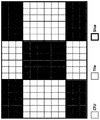
- FIG. 24 shows an example of an image of HEC in 3x2 layout.
- FIG. 25 shows an example of number of padded lines for samples of two kinds of boundaries.
- FIG. 26 shows an example of processing of CTUs in a picture.
- FIG. 27 shows another example of processing of CTUs in a picture.
- FIG. 28 is a block diagram of an example video processing system in which disclosed techniques may be implemented.
- FIG. 29 is a flowchart representation of a method for video processing in accordance with the present technology.
- FIG. 30 is another flowchart representation of a method for video processing in accordance with the present technology.
- FIG. 31 is another flowchart representation of a method for video processing in accordance with the present technology.
- FIG. 32 is another flowchart representation of a method for video processing in accordance with the present technology.
- FIG. 33 is another flowchart representation of a method for video processing in accordance with the present technology.
- FIG. 34 is another flowchart representation of a method for video processing in accordance with the present technology.
- FIG. 35 is another flowchart representation of a method for video processing in accordance with the present technology.
- FIG. 36 is another flowchart representation of a method for video processing in accordance with the present technology.
- FIG. 37 is another flowchart representation of a method for video processing in accordance with the present technology.
- FIG. 38 is yet another flowchart representation of a method for video processing in accordance with the present technology.
- Section headings are used in the present document to facilitate ease of understanding and do not limit the embodiments disclosed in a section to only that section.
- certain embodiments are described with reference to Versatile Video Coding or other specific video codecs, the disclosed techniques are applicable to other video coding technologies also.
- video processing encompasses video coding or compression, video decoding or decompression and video transcoding in which video pixels are represented from one compressed format into another compressed format or at a different compressed bitrate.
- This document is related to video coding technologies. Specifically, it is related to picture/slice/tile/brick boundary and virtual boundary coding especially for the non-linear adaptive loop filter. It may be applied to the existing video coding standard like HEVC, or the standard (Versatile Video Coding) to be finalized. It may be also applicable to future video coding standards or video codec.
- Video coding standards have evolved primarily through the development of the well-known ITU-T and ISO/IEC standards.
- the ITU-T produced H. 261 and H. 263, ISO/IEC produced MPEG-1 and MPEG-4 Visual, and the two organizations jointly produced the H. 262/MPEG-2 Video and H. 264/MPEG-4 Advanced Video Coding (AVC) and H. 265/HEVC standards.
- AVC H. 264/MPEG-4 Advanced Video Coding
- H. 265/HEVC High Efficiency Video Coding
- the video coding standards are based on the hybrid video coding structure wherein temporal prediction plus transform coding are utilized.
- Joint Video Exploration Team JVET was founded by VCEG and MPEG jointly in 2015.
- JVET Joint Exploration Model
- Color space also known as the color model (or color system)
- color model is an abstract mathematical model which simply describes the range of colors as tuples of numbers, typically as 3 or 4 values or color components (e.g. RGB) .
- color space is an elaboration of the coordinate system and sub-space.
- YCbCr, Y′CbCr, or Y Pb/Cb Pr/Cr also written as YCBCR or Y'CBCR, is a family of color spaces used as a part of the color image pipeline in video and digital photography systems.
- Y′ is the luma component and CB and CR are the blue-difference and red- difference chroma components.
- Y′ (with prime) is distinguished from Y, which is luminance, meaning that light intensity is nonlinearly encoded based on gamma corrected RGB primaries.
- Chroma subsampling is the practice of encoding images by implementing less resolution for chroma information than for luma information, taking advantage of the human visual system's lower acuity for color differences than for luminance.
- Each of the three Y'CbCr components have the same sample rate, thus there is no chroma subsampling. This scheme is sometimes used in high-end film scanners and cinematic post production.
- the two chroma components are sampled at half the sample rate of luma: the horizontal chroma resolution is halved. This reduces the bandwidth of an uncompressed video signal by one-third with little to no visual difference
- Cb and Cr are cosited horizontally.
- Cb and Cr are sited between pixels in the vertical direction (sited interstitially) .
- Cb and Cr are sited interstitially, halfway between alternate luma samples.
- Cb and Cr are co-sited in the horizontal direction. In the vertical direction, they are co-sited on alternating lines.
- a picture is divided into one or more tile rows and one or more tile columns.
- a tile is a sequence of CTUs that covers a rectangular region of a picture.
- a tile is divided into one or more bricks, each of which consisting of a number of CTU rows within the tile.
- a tile that is not partitioned into multiple bricks is also referred to as a brick.
- a brick that is a true subset of a tile is not referred to as a tile.
- a slice either contains a number of tiles of a picture or a number of bricks of a tile.
- a slice contains a sequence of tiles in a tile raster scan of a picture.
- a slice contains a number of bricks of a picture that collectively form a rectangular region of the picture. The bricks within a rectangular slice are in the order of brick raster scan of the slice.
- FIG. 1 shows an example of raster-scan slice partitioning of a picture, where the picture is divided into 12 tiles and 3 raster-scan slices.
- FIG. 2 shows an example of rectangular slice partitioning of a picture, where the picture is divided into 24 tiles (6 tile columns and 4 tile rows) and 9 rectangular slices.
- FIG. 3 shows an example of a picture partitioned into tiles, bricks, and rectangular slices, where the picture is divided into 4 tiles (2 tile columns and 2 tile rows) , 11 bricks (the top-left tile contains 1 brick, the top-right tile contains 5 bricks, the bottom-left tile contains 2 bricks, and the bottom-right tile contain 3 bricks) , and 4 rectangular slices.
- the CTU size, signaled in SPS by the syntax element log2_ctu_size_minus2, could be as small as 4x4.
- log2_ctu_size_minus2 plus 2 specifies the luma coding tree block size of each CTU.
- log2_min_luma_coding_block_size_minus2 plus 2 specifies the minimum luma coding block size.
- MinCbLog2SizeY log2_min_luma_coding_block_size_minus2+2 (7-11)
- MinCbSizeY 1 ⁇ MinCbLog2SizeY (7-12)
- MinTbSizeY 1 ⁇ MinTbLog2SizeY (7-15)
- MaxTbSizeY 1 ⁇ MaxTbLog2SizeY (7-16)
- PicWidthInCtbsY Ceil (pic_width_in_luma_samples ⁇ CtbSizeY) (7-17)
- PicHeightInCtbsY Ceil (pic_height_in_luma_samples ⁇ CtbSizeY) (7-18)
- PicSizeInCtbsY PicWidthInCtbsY*PicHeightInCtbsY (7-19)
- PicWidthInMinCbsY pic_width_in_luma_samples/MinCbSizeY (7-20)
- PicHeightInMinCbsY pic_height_in_luma_samples/MinCbSizeY (7-21)
- PicSizeInMinCbsY PicWidthInMinCbsY*PicHeightInMinCbsY (7-22)
- PicSizeInSamplesY pic_width_in_luma_samples*pic_height_in_luma_samples (7-23)
- PicWidthInSamplesC pic_width_in_luma_samples/SubWidthC (7-24)
- PicHeightInSamplesC pic_height_in_luma_samples/SubHeightC (7-25)
- the CTB/LCU size indicated by M x N (typically M is equal to N, as defined in HEVC/VVC)
- K x L samples are within picture border wherein either K ⁇ M or L ⁇ N.
- the CTB size is still equal to MxN, however, the bottom boundary/right boundary of the CTB is outside the picture.
- FIG. 4A shows CTBs crossing the bottom picture border.
- FIG. 4B shows CTBs crossing the right picture border.
- FIG. 4C shows CTBs crossing the right bottom picture border
- FIG. 5 shows an example of encoder block diagram of VVC, which contains three in-loop filtering blocks: deblocking filter (DF) , sample adaptive offset (SAO) and ALF.
- DF deblocking filter
- SAO sample adaptive offset
- ALF utilize the original samples of the current picture to reduce the mean square errors between the original samples and the reconstructed samples by adding an offset and by applying a finite impulse response (FIR) filter, respectively, with coded side information signaling the offsets and filter coefficients.
- FIR finite impulse response
- ALF is located at the last processing stage of each picture and can be regarded as a tool trying to catch and fix artifacts created by the previous stages.
- the input of DB is the reconstructed samples before in-loop filters.
- the vertical edges in a picture are filtered first. Then the horizontal edges in a picture are filtered with samples modified by the vertical edge filtering process as input.
- the vertical and horizontal edges in the CTBs of each CTU are processed separately on a coding unit basis.
- the vertical edges of the coding blocks in a coding unit are filtered starting with the edge on the left-hand side of the coding blocks proceeding through the edges towards the right-hand side of the coding blocks in their geometrical order.
- the horizontal edges of the coding blocks in a coding unit are filtered starting with the edge on the top of the coding blocks proceeding through the edges towards the bottom of the coding blocks in their geometrical order.
- FIG. 6 is an illustration of picture samples and horizontal and vertical block boundaries on the 8 ⁇ 8 grid, and the nonoverlapping blocks of the 8 ⁇ 8 samples, which can be deblocked in parallel.
- Filtering is applied to 8x8 block boundaries. In addition, it must be a transform block boundary or a coding subblock boundary (e.g., due to usage of Affine motion prediction, ATMVP) . For those which are not such boundaries, filter is disabled.
- FIG. 7 shows examples of pixels involved in filter on/off decision and strong/weak filter selection.
- Wider-stronger luma filter is filters are used only if all the Condition1, Condition2 and Condition 3 are TRUE.
- the condition 1 is the “large block condition” . This condition detects whether the samples at P-side and Q-side belong to large blocks, which are represented by the variable bSidePisLargeBlk and bSideQisLargeBlk respectively.
- the bSidePisLargeBlk and bSideQisLargeBlk are defined as follows.
- condition 1 Based on bSidePisLargeBlk and bSideQisLargeBlk, the condition 1 is defined as follows.
- Condition1 and Condition2 are valid, whether any of the blocks uses sub-blocks is further checked:
- condition 3 the large block strong filter condition
- dpq is derived as in HEVC.
- StrongFilterCondition (dpq is less than ( ⁇ >>2) , sp 3 +sq 3 is less than (3* ⁇ >>5) , and Abs (p 0 -q 0 ) is less than (5*t C +1) >>1) ? TRUE : FALSE.
- Bilinear filter is used when samples at either one side of a boundary belong to a large block.
- the bilinear filter is listed below.
- tcPD i and tcPD j term is a position dependent clipping described in Section 2.4.7 and g j , f i , Middle s, t , P s and Q s are given below:
- the chroma strong filters are used on both sides of the block boundary.
- the chromafilter is selected when both sides of the chroma edge aregreater than or equal to 8 (chroma position) , and the following decision with three conditions are satisfied: the first one is for decision of boundary strength as well as large block.
- the proposed filter can be applied when the block width or height which orthogonally crosses the block edge is equal to or larger than 8 in chroma sample domain.
- the second and third one is basically the same as for HEVC luma deblocking decision, which are on/off decision and strong filter decision, respectively.
- boundary strength (bS) is modified for chroma filtering and the conditions are checked sequentially. If a condition is satisfied, then the remaining conditions with lower priorities are skipped.
- Chroma deblocking is performed when bS is equal to 2, or bS is equal to 1 when a large block boundary is detected.
- the second and third condition is basically the same as HEVC luma strong filter decision as follows.
- d is then derived as in HEVC luma deblocking.
- the second condition will be TRUE when d is less than ⁇ .
- dpq is derived as in HEVC.
- the proposed chroma filter performs deblocking on a 4x4 chroma sample grid.
- the position dependent clipping tcPD is applied to the output samples of the luma filtering process involving strong and long filters that are modifying 7, 5 and 3 samples at the boundary. Assuming quantization error distribution, it is proposed to increase clipping value for samples which are expected to have higher quantization noise, thus expected to have higher deviation of the reconstructed sample value from the true sample value.
- position dependent threshold table is selected from two tables (e.g., Tc7 and Tc3 tabulated below) that are provided to decoder as a side information:
- Tc7 ⁇ 6, 5, 4, 3, 2, 1, 1 ⁇ ;
- Tc3 ⁇ 6, 4, 2 ⁇ ;
- position dependent threshold For the P or Q boundaries being filtered with a short symmetrical filter, position dependent threshold of lower magnitude is applied:
- Tc3 ⁇ 3, 2, 1 ⁇ ;
- filtered p’ i and q’ i sample values are clipped according to tcP and tcQ clipping values:
- p’ i and q’ i are filtered sample values
- p” i and q” j are output sample value after the clipping
- tcP i tcP i are clipping thresholds that are derived from the VVC tc parameter and tcPD and tcQD.
- the function Clip3 is a clipping function as it is specified in VVC.
- the long filters is restricted to modify at most 5 samples on a side that uses sub-block deblocking (AFFINE or ATMVP or DMVR) as shown in the luma control for long filters. Additionally, the sub-block deblocking is adjusted such that that sub-block boundaries on an 8x8 grid that are close to a CU or an implicit TU boundary is restricted to modify at most two samples on each side.
- AFFINE or ATMVP or DMVR sub-block deblocking
- edge equal to 0 corresponds to CU boundary
- edge equal to 2 or equal to orthogonalLength-2 corresponds to sub-block boundary 8 samples from a CU boundary etc.
- implicit TU is true if implicit split of TU is used.
- the input of SAO is the reconstructed samples after DB.
- the concept of SAO is to reduce mean sample distortion of a region by first classifying the region samples into multiple categories with a selected classifier, obtaining an offset for each category, and then adding the offset to each sample of the category, where the classifier index and the offsets of the region are coded in the bitstream.
- the region (the unit for SAO parameters signaling) is defined to be a CTU.
- SAO types Two SAO types that can satisfy the requirements of low complexity are adopted in HEVC. Those two types are edge offset (EO) and band offset (BO) , which are discussed in further detail below.
- An index of an SAO type is coded (which is in the range of [0, 2] ) .
- EO edge offset
- BO band offset
- An index of an SAO type is coded (which is in the range of [0, 2] ) .
- the sample classification is based on comparison between current samples and neighboring samples according to 1-D directional patterns: horizontal, vertical, 135° diagonal, and 45° diagonal.
- each sample inside the CTB is classified into one of five categories.
- the current sample value labeled as “c, ” is compared with its two neighbors along the selected 1-D pattern.
- the classification rules for each sample are summarized in Table I. Categories 1 and 4 are associated with a local valley and a local peak along the selected 1-D pattern, respectively. Categories 2 and 3 are associated with concave and convex corners along the selected 1-D pattern, respectively. If the current sample does not belong to EO categories 1–4, then it is category 0 and SAO is not applied.
- the input of DB is the reconstructed samples after DB and SAO.
- the sample classification and filtering process are based on the reconstructed samples after DB and SAO.
- a geometry transformation-based adaptive loop filter (GALF) with block-based filter adaption is applied.
- GLF geometry transformation-based adaptive loop filter
- For the luma component one among 25 filters is selected for each 2 ⁇ 2 block, based on the direction and activity of local gradients.
- up to three diamond filter shapes can be selected for the luma component.
- An index is signalled at the picture level to indicate the filter shape used for the luma component.
- Each square represents a sample, and Ci (i being 0 ⁇ 6 (left) , 0 ⁇ 12 (middle) , 0 ⁇ 20 (right) ) denotes the coefficient to be applied to the sample.
- Ci being 0 ⁇ 6 (left) , 0 ⁇ 12 (middle) , 0 ⁇ 20 (right)
- the 5 ⁇ 5 diamond shape is always used.
- Each 2 ⁇ 2 block is categorized into one out of 25 classes.
- the classification index C is derived based on its directionality Dand a quantized value of activity as follows:
- Indices i and j refer to the coordinates of the upper left sample in the 2 ⁇ 2 block and R (i, j) indicates a reconstructed sample at coordinate (i, j) .
- D maximum and minimum values of the gradients of horizontal and vertical directions are set as:
- Step 1 If both and are true, D is set to 0.
- Step 2 If continue from Step 3; otherwise continue from Step 4.
- Step 3 If D is set to 2; otherwise D is set to 1.
- the activity value A is calculated as:
- A is further quantized to the range of 0 to 4, inclusively, and the quantized value is denoted as
- no classification method is applied, e.g. asingle set of ALF coefficients is applied for each chroma component.
- FIG. 10 shows relative coordinator for the 5 ⁇ 5 diamond filter support: Left: Diagonal Center: Vertical flip, Right: Rotation.
- K is the size of the filter and 0 ⁇ k, l ⁇ K-1 are coefficients coordinates, such that location (0, 0) is at the upper left corner and location (K-1, K-1) is at the lower right corner.
- the transformations are applied to the filter coefficients f (k, l) depending on gradient values calculated for that block.
- the relationship between the transformation and the four gradients of the four directions are summarized in Table 4.
- FIG. 9 shows the transformed coefficients for each position based on the 5x5 diamond.
- GALF filter parameters are signalled for the first CTU, e.g., after the slice header and before the SAO parameters of the first CTU. Up to 25 sets of luma filter coefficients could be signalled. To reduce bits overhead, filter coefficients of different classification can be merged.
- the GALF coefficients of reference pictures are stored and allowed to be reused as GALF coefficients of a current picture. The current picture may choose to use GALF coefficients stored for the reference pictures and bypass the GALF coefficients signalling. In this case, only an index to one of the reference pictures is signalled, and the stored GALF coefficients of the indicated reference picture are inherited for the current picture.
- a candidate list of GALF filter sets is maintained. At the beginning of decoding a new sequence, the candidate list is empty. After decoding one picture, the corresponding set of filters may be added to the candidate list. Once the size of the candidate list reaches the maximum allowed value (e.g., 6) , a new set of filters overwrites the oldest set in decoding order, and that is, first-in-first-out (FIFO) rule is applied to update the candidate list. To avoid duplications, a set could only be added to the list when the corresponding picture doesn’t use GALF temporal prediction. To support temporal scalability, there are multiple candidate lists of filter sets, and each candidate list is associated with a temporal layer.
- each array assigned by temporal layer index may compose filter sets of previously decoded pictures with equal to lower TempIdx.
- the k-th array is assigned to be associated with TempIdx equal to k, and it only contains filter sets from pictures with TempIdx smaller than or equal to k. After coding a certain picture, the filter sets associated with the picture will be used to update those arrays associated with equal or higher TempIdx.
- Temporal prediction of GALF coefficients is used for inter coded frames to minimize signalling overhead.
- temporal prediction is not available, and a set of 16 fixed filters is assigned to each class.
- a flag for each class is signalled and if required, the index of the chosen fixed filter.
- the coefficients of the adaptive filter f (k, l) can still be sent for this class in which case the coefficients of the filter which will be applied to the reconstructed image are sum of both sets of coefficients.
- the filtering process of luma component can controlled at CU level.
- a flag is signalled to indicate whether GALF is applied to the luma component of a CU.
- For chroma component whether GALF is applied or not is indicated at picture level only.
- each sample R (i, j) within the block is filtered, resulting in sample value R′ (i, j) as shown below, where L denotes filter length, f m, n represents filter coefficient, and f (k, l) denotes the decoded filter coefficients.
- FIG. 11 shows an example of relative coordinates used for 5x5 diamond filter support supposing the current sample’s coordinate (i, j) to be (0, 0) . Samples in different coordinates filled with the same color are multiplied with the same filter coefficients.
- the filtering process of the Adaptive Loop Filter is performed as follows:
- L denotes the filter length
- w (i, j) are the filter coefficients in fixed point precision.
- the adaptive filter shape is removed. Only 7x7 filter shape is allowed for luma component and 5x5 filter shape is allowed for chroma component.
- FIG. 12A-12D show Subsampled Laplacian calculation for CE2.6.2.
- FIG. 12 A illustrates subsampledpositions for vertical gradient
- FIG. 12 illustrates subsampled positions for horizontal gradient
- FIG. 12C illustrates subsampled positions for diagonal gradient
- FIG. 12D illustrates subsampled positions for diagonal gradient.
- Equation (11) can be reformulated, without coding efficiency impact, in the following expression:
- VVC introduces the non-linearity to make ALF more efficient by using a simple clipping function to reduce the impact of neighbor sample values (I (x+i, y+j) ) when they are too different with the current sample value (I (x, y) ) being filtered.
- the ALF filter is modified as follows:
- O′ (x, y) I (x, y) + ⁇ (i, j) ⁇ (0, 0) w (i, j) .
- K (d, b) min (b, max (-b, d) ) is the clipping function
- k (i, j) are clipping parameters, which depends on the (i, j) filter coefficient.
- the encoder performs the optimization to find the best k (i, j) .
- the clipping parameters k (i, j) are specified for each ALF filter, one clipping value is signaled per filter coefficient. It means that up to 12 clipping values can be signalled in the bitstream per Luma filter and up to 6 clipping values for the Chroma filter.
- the sets of clipping values used in some embodiments are provided in the Table 5.
- the 4 values have been selected by roughly equally splitting, in the logarithmic domain, the full range of the sample values (coded on 10 bits) for Luma, and the range from 4 to 1024 for Chroma.
- Luma table of clipping values More precisely, the Luma table of clipping values have been obtained by the following formula:
- Chroma tables of clipping values is obtained according to the following formula:
- the selected clipping values are coded in the “alf_data” syntax element by using a Golomb encoding scheme corresponding to the index of the clipping value in the above Table 5.
- This encoding scheme is the same as the encoding scheme for the filter index.
- the total number of line buffers required is 11.25 lines for the Luma component.
- the explanation of the line buffer requirement is as follows: The deblocking of horizontal edge overlapping with CTU edge cannot be performed as the decisions and filtering require lines K, L, M, M from the first CTU and Lines O, P from the bottom CTU. Therefore, the deblocking of the horizontal edges overlapping with the CTU boundary is postponed until the lower CTU comes. Therefore for the lines K, L, M, N reconstructed luma samples have to be stored in the line buffer (4 lines) . Then the SAO filtering can be performed for lines A till J. The line J can be SAO filtered as deblocking does not change the samples in line K.
- the edge offset classification decision is only stored in the line buffer (which is 0.25 Luma lines) .
- the ALF filtering can only be performed for lines A-F. As shown in FIG. 13, the ALF classification is performed for each 4 x 4 block. Each 4 x 4 block classification needs an activity window of size 8 x 8 which in turn needs a 9 x 9 window to compute the 1d Laplacian to determine the gradient.
- the line buffer requirement of the Chroma component is illustrated in FIG. 14.
- the line buffer requirement for Chroma component is evaluated to be 6.25 lines.
- VBs are upward shifted horizontal LCU boundaries by N pixels.
- SAO and ALF can process pixels above the VB before the lower LCU comes but cannot process pixels below the VB until the lower LCU comes, which is caused by DF.
- the block classification only uses the lines E till J.
- Laplacian gradient calculation for the samples belonging to line J requires one more line below (line K) . Therefore, line K is padded with line J.
- truncated version of the filters is used for filtering of the luma samples belonging to the lines close to the virtual boundaries.
- the line M as denoted in FIG. 13, e.g., the center sample of the 7x7 diamond support is in the line M. it requires to access one line above the VB (denoted by bold line) .
- the samples above the VB is copied from the right below sample below the VB, such as the P0 sample in the solid line is copied to the above dash position.
- P3 sample in the solid line is also copied to the right below dashed position even the sample for that position is available.
- the copied samples are only used in the luma filtering process.
- the padding method used for ALF virtual boundaries may be denoted as ‘Two-side Padding’ wherein if one sample located at (i, j) (e.g., the P0A with dash line in FIG. 16B) is padded, then the corresponding sample located at (m, n) (e.g., the P3B with dash line in FIG. 16B) which share the same filter coefficient is also padded even the sample is available, as depicted in FIGS. 16A-16C and FIGS. 17A-17B.
- FIGS. 16A-16C 7x7 diamond filter support, center is the current sample to be filtered.
- FIG. 16A shows one required line above/below VB need to be padded.
- FIG. 16B shows 2 required lines above/below VB need to be padded.
- FIG. 16C shows 3 required lines above/below VB need to be padded.
- FIGS. 17A-17B show modified chroma ALF filtering at virtual boundary (5x5 diamond filter support, center is the current sample to be filtered) .
- FIG. 17A shows 1 required lines above/below VB need to be padded.
- FIG. 17B shows 2 required lines above/below VB need to be padded.
- the padding process could be replaced by modifying the filter coefficients (a.k.a modified-coeff based ALF, MALF) .
- the filter coefficient c5 is modified to c5’ , in this case, there is no need to copy the luma samples from the solid P0A to dashed P0A and solid P3B to dashed P3B FIG. 18A.
- the two-side padding and MALF will generate the same results, assuming the current sample to be filtered is located at (x, y) .
- K (I (x-1, y-2) -I (x, y) , k (-1, -2) ) (c5+c1) .
- K (I (x-1, y-2) -I (x, y) , k (-1, -2) ) ! (c5+c1) .
- Newly added parts are indicated in bold italicized underlined text.
- the deleted parts are indicated using [ [] ] .
- loop_filter_across_bricks_enabled_flag 1 specifies that in-loop filtering operations may be performed across brick boundaries in pictures referring to the PPS.
- loop_filter_across_bricks_enabled_flag 0 specifies that in-loop filtering operations are not performed across brick boundaries in pictures referring to the PPS.
- the in-loop filtering operations include the deblocking filter, sample adaptive offset filter, and adaptive loop filter operations. When not present, the value of loop_filter_across_bricks_enabled_flag is inferred to be equal to 1.
- loop_filter_across_slices_enabled_flag 1 specifies that in-loop filtering operations may be performed across slice boundaries in pictures referring to the PPS.
- loop_filter_across_slice_enabled_flag 0 specifies that in-loop filtering operations are not performed across slice boundaries in pictures referring to the PPS.
- the in-loop filtering operations include the deblocking filter, sample adaptive offset filter, and adaptive loop filter operations. When not present, the value of loop_filter_across_slices_enabled_flag is inferred to be equal to 0.
- pps_loop_filter_across_virtual_boundaries_disabled_flag 1 specifies that the in-loop filtering operations are disabled across the virtual boundaries in pictures referring to the PPS.
- pps_loop_filter_across_virtual_boundaries_disabled_flag 0 specifies that no such disabling of in-loop filtering operations is applied in pictures referring to the PPS.
- the in-loop filtering operations include the deblocking filter, sample adaptive offset filter, and adaptive loop filter operations. When not present, the value of pps_loop_filter_across_virtual_boundaries_disabled_flag is inferred to be equal to 0.
- pps_num_ver_virtual_boundaries specifies the number of pps_virtual_boundaries_pos_x [i] syntax elements that are present in the PPS. When pps_num_ver_virtual_boundaries is not present, it is inferred to be equal to 0.
- a luma location (xCtb, yCtb) specifying the top-left sample of the current luma coding tree block relative to the top left sample of the current picture.
- Output of this process is the modified filtered reconstructed luma picture sample array alfPicture L .
- i slice_alf_aps_id_luma [AlfCtbFiltSetIdxY [xCtb>>Log2CtbSize] [yCtb>>Log2CtbSize] -16] (8-1175)
- the luma filter coefficients and clipping values index idx are derived depending on transposeIdx [x] [y] as follows:
- transposeIndex [x] [y] is equal to 1, the following applies:
- idx [] ⁇ 9, 4, 10, 8, 1, 5, 11, 7, 3, 0, 2, 6 ⁇ (8-1178)
- transposeIndex [x] [y] is equal to 2
- idx [] ⁇ 0, 3, 2, 1, 8, 7, 6, 5, 4, 9, 10, 11 ⁇ (8-1179)
- transposeIndex [x] [y] is equal to 3
- idx [] ⁇ 9, 8, 10, 4, 3, 7, 11, 5, 1, 0, 2, 6 ⁇ (8-1180)
- idx [] ⁇ 0, 1, 2, 3, 4, 5, 6, 7, 8, 9, 10, 11 ⁇ (8-1181)
- pps_num_ver_virtual_boundaries-1 the following applies:
- h x+i Clip3 (PpsVirtualBoundariesPosX [n] , pic_width_in_luma_samples-1, xCtb+x+i) (8-1182)
- pps_num_ver_virtual_boundaries-1 the following applies:
- h x+i Clip3 (0, pic_width_in_luma_samples-1, xCtb+x+i) (8-1184)
- pps_num_hor_virtual_boundaries-1 the following applies:
- v y+j Clip3 (PpsVirtualBoundariesPosY [n] , pic_height_in_luma_samples-1, yCtb+y+j) (8-1185)
- pps_num_hor_virtual_boundaries-1 the following applies:
- v y+j Clip3 (0, pic_height_in_luma_samples-1, yCtb+y+j) (8-1187)
- the bottom boundary of the current coding tree block is the bottom boundary of the picture.
- the bottom boundary of the current coding tree block is the bottom boundary of the brick and loop_filter_across_bricks_enabled_flag is equal to 0.
- the bottom boundary of the current coding tree block is the bottom boundary of the slice and loop_filter_across_slices_enabled_flag is equal to 0.
- the bottom boundary of the current coding tree block is one of the bottom virtual boundaries of the picture and pps_loop_filter_across_virtual_boundaries_disabled_flag is equal to 1.
- applyVirtualBoundary is set equal to 1.
- the reconstructed sample offsets r1, r2 and r3 are specified in Table 8-22 according to the horizontal luma sample position y and applyVirtualBoundary.
- variable curr is derived as follows:
- curr recPicture L [h x , v y ] (8-1188)
- variable sum is derived as follows:
- chroma location (xCtbC, yCtbC) specifying the top-left sample of the current chroma coding tree block relative to the top left sample of the current picture.
- Output of this process is the modified filtered reconstructed chroma picture sample array alfPicture.
- the width and height of the current chroma coding tree block ctbWidthC and ctbHeightC is derived as follows:
- ctbWidthC CtbSizeY/SubWidthC (8-1230)
- pps_num_ver_virtual_boundaries-1 the following applies:
- pps_num_ver_virtual_boundaries-1 the following applies:
- h x+i Clip3 (0, PpsVirtualBoundariesPosX [n] /SubWidthC-1, xCtbC+x+i) (8-1233)
- h x+i Clip3 (0, pic_width_in_luma_samples/SubWidthC-1, xCtbC+x+i) (8-1234)
- pps_num_hor_virtual_boundaries-1 the following applies:
- pps_num_hor_virtual_boundaries-1 the following applies:
- v y+j Clip3 (0, PpsVirtualBoundariesPosY [n] /SubHeightC-1, yCtbC+y+j) (8-1236)
- v y+j Clip3 (0, pic_height_in_luma_samples/SubHeightC-1, yCtbC+y+j) (8-1237)
- the bottom boundary of the current coding tree block is the bottom boundary of the picture.
- the bottom boundary of the current coding tree block is the bottom boundary of the brick and loop_filter_across_bricks_enabled_flag is equal to 0.
- the bottom boundary of the current coding tree block is the bottom boundary of the slice and loop_filter_across_slices_enabled_flag is equal to 0.
- the bottom boundary of the current codingtree block is one of the bottom virtual boundaries of the picture and pps_loop_filter_across_virtual_boundaries_disabled_flag is equal to 1.
- applyVirtualBoundary is set equal to 1.
- the reconstructed sample offsets r1 and r2 are specified in Table 8-22 according to the horizontal luma sample position y and applyVirtualBoundary.
- variable curr is derived as follows:
- curr recPicture [h x , v y ] (8-1238)
- variable sum is derived as follows:
- the ALF virtual boundary handling method is disabled. For example, one picture is split to multiple CTUs and 2 slices as depicted FIG. 19.
- the last 4 lines within a CTB are treated below a virtual boundary.
- the bottom boundary of the CTB is the bottom boundary of a picture (e.g., CTU-D) , it processes the (M+4) ⁇ M block including 4 lines from above CTU row and all lines in current CTU.
- a picture e.g., CTU-D
- a CTU/CTB in the first CTU row in a slice/brick/tile e.g., CTU-A
- a CTU/CTB in not in the first CTU row of a slice/brick/tile (e.g., CTU-B) and not in the last CTU row of a of a slice/brick/tile, it processes the M ⁇ M block including 4 lines from above CTU row and excluding the last 4 lines in current CTU.
- FIG. 19 shows an example of processing of CTUs in a picture.
- the horizontal wrap around motion compensation in the VTM5 is a 360-specific coding tool designed to improve the visual quality of reconstructed 360-degree video in the equi-rectangular (ERP) projection format.
- ERP equi-rectangular
- conventional motion compensation when a motion vector refers to samples beyond the picture boundaries of the reference picture, repetitive padding is applied to derive the values of the out-of-bounds samples by copying from those nearest neighbors on the corresponding picture boundary.
- this method of repetitive padding is not suitable, and could cause visual artefacts called “seam artefacts” in a reconstructed viewport video.
- FIG. 20 shows an example of horizontal wrap around motion compensation in VVC.
- the horizontal wrap around motion compensation process is as depicted in FIG. 20.
- the “out-of-boundary” part is taken from the corresponding spherical neighbors that are of the reference picture toward the right (or left) boundary in the projected domain.
- Repetitive padding is only used for the top and bottom picture boundaries.
- thehorizontal wrap around motion compensation can be combined with the non-normative padding method often used in 360-degree video coding.
- VVC VVC
- this is achieved by signaling a high-level syntax element to indicate the wrap-around offset, which should be set to the ERP picture width before padding; this syntax is used to adjust the position of horizontal wrap around accordingly.
- This syntax is not affected by the specific amount of padding on the left and right picture boundaries, and therefore naturally supports asymmetric padding of the ERP picture, e.g., when left and right padding are different.
- the horizontal wrap around motion compensation provides more meaningful information for motion compensation when the reference samples are outside of the reference picture’s left and right boundaries.
- in-loop filtering operations may be disabled across discontinuities in the frame-packed picture.
- a syntax was proposed to signal vertical and/or horizontal virtual boundaries across which the in-loop filtering operations are disabled. Compared to using two tiles, one for each set of continuous faces, and to disable in-loop filtering operations across tiles, the proposed signaling method is more flexible as it does not require the face size to be a multiple of the CTU size
- Whether in-loop filtering across sub-picture boundaries is disabled can be controlled by the bitstream for each sub-picture.
- the DBF, SAO, and ALF processes are updated for controlling of in-loop filtering operations across sub-picture boundaries.
- sub-picture width, height, horizontal offset, and vertical offset are signalled in units of luma samples in SPS.
- Sub-picture boundaries are constrained to be slice boundaries.
- Treating a sub-picture as a picture in the decoding process is specified by slightly updating the coding_tree_unit () syntax, and updates to the following decoding processes:
- Sub-picture IDs are explicitly specified in the SPS and included in the tile group headers to enable extraction of sub-picture sequences without the need of changing VCL NAL units.
- OSPS Output sub-picture sets
- the current VVC design has the following problems:
- the current setting of enabling ALF virtual boundary is dependent on whether the bottom boundary of a CTB is a bottom boundary of a picture. If it is true, then ALF virtual boundary is disabled, such as CTU-D in FIG. 19. However, it is possible that a bottom boundary of a CTB is outside a bottom boundary of a picture, such as 256x240 picture is split to 4 128x128 CTUs, in this case, the ALF virtual boundary would be wrongly set to true for the last 2 CTUs which has samples outside of the bottom picture boundary.
- ALF virtual boundary is disabled for bottom picture boundary and slice/tile/brick boundary. Disabling VB along slice/brick boundary may create pipeline bubble or require processing 68 lines per Virtual pipeline data units (VPDU, 64x64 in VVC) assuming the LCU size to be 64x64. For example:
- the ALF line buffers need to be restored. Whether the content in the line buffers get used or not for the ALF filtering depends on whether the current CTU is also a slice/brick/tile boundary CTU, this information, however, is unknown until the next slice/brick/tile is decoded.
- the decoders need to live with pipeline bubbles (very unlikely) or run the ALF at a speed of 68 lines per 64x64 VDPU all the time (overprovision) , to avoid using the ALF line buffers.
- the padding method for 360 degree virtual boundary may be firstly applied to generate virtual samples below the 360 degree virtual boundary. Afterwards, these virtual samples located below the 360 degree virtual boundary are treated as being available. And the ALF 2-side padding method may be further applied according to FIG. 16 A-C. An example is depicted in FIG. 25.
- the way for handling virtual boundary may be sub-optimal, since padded samples are utilized which may be less efficient.
- the non-linear ALF is disabled, the MALF and two-side padding methods would be able to generate the same results for filtering a sample which requires to access samples crossing virtual boundary. However, when the the non-linear ALF is enabled, the two methods would bring different results. It would be beneficial to align the two cases.
- the padding method used for ALF virtual boundaries may be denoted as ‘Two-side Padding’ wherein if one sample located at (i, j) is padded, then the corresponding sample located at (m, n) which share the same filter coefficient is also padded even the sample is available, as depicted in FIGS. 12-13.
- the padding method used for picture boundaries/360-degree video virtual boundaries may be denoted as ‘One-side Padding’ wherein if one sample to be used is outside the boundaries, it is copied from an available one inside the picture.
- the padding method used for 360-degree video left and right boundaries may be denoted as ‘wrapping-base Padding’ wherein if one sample to be used is outside the boundaries, it is copied using the motion compensated results.
- a sample is “at a boundary of a video unit” may mean that the distance between the sample and the boundary of the video unit is less or no greater than a threshold.
- a “line” may refer to samples at one same horizontal position or samples at one same vertical position. (e.g., samples in the same row and/or samples in the same column) .
- Function Abs (x) is defined as follows:
- a “virtual sample” refers to a generated sample which may be different from the reconstructed sample (may be processed by deblocking and/or SAO) .
- a virtual sample may be used to conduct ALF for another sample.
- the virtual sample may be generated by padding.
- ‘ALF virtual boundary handling method is enabled for one block’ may indicate that applyVirtualBoundary in the specification is set to true. ‘Enabling virtual boundary’ may indicate that the current block is split to at least two parts by a virtual boundary and the samples located in one part are disallowed to utilize samples in the other part in the filtering process (e.g., ALF) .
- the virtual boundary may be K rows above the bottom boundary of one block.
- the neighboring samples may be those which are required for the filter classification and/or filtering process.
- a neighbouring sample is “unavailable” if it is out of the current picture, or current sub-picture, or current tile, or current slice, or current brick, or current CTU, or current processing unit (such as ALF processing unit or narrow ALF processing unit) , or any other current video unit.
- current processing unit such as ALF processing unit or narrow ALF processing unit
- the determination of ‘The bottom boundary of the current coding tree block is the bottom boundary of the picture’ is replaced by ‘The bottom boundary of the current coding tree block is the bottom boundary of the picture or outside the picture’ .
- the ALF virtual boundary handling method may be disabled.
- Whether to enable the usage of virtual samples may depend on the CTB size.
- ALF is disabled for certain CTU/CTB sizes, such as 4x4, 8x8.
- Whether to enable the usage of virtual samples (e.g, padded from reconstructed samples) in the in-loop filtering processes may depend on whether the bottom boundary of the block is the bottom boundary of a video unit which is in a finer granularity compared to a picture (e.g., slice/tile/brick) or a virtual boundary.
- the ALF virtual boundary handling method may be enabled (e.g., applyVirtualBoundaryis set to true) for a coding tree block (CTB) if the bottom boundary of the CTB is the boundary of the video unit or a virtual boundary.
- CTB coding tree block
- the above method is enabled.
- the ALF virtual boundary handling method may still be enabled (e.g., applyVirtualBoundary is set to true) .
- whether to enable the ALF virtual boundary handling method (e.g., value of applyVirtualBoundary) for a CTB may only depend on the relationship between the bottom boundary of the CTB and the bottom boundary of a picture.
- applyVirtualBoundary is set to false only if the bottom boundary of the CTB is the bottom boundary of a picture containing the CTB or if the bottom boundary is outside the picture.
- applyVirtualBoundary is set to true when the bottom boundary of the CTB is NOT the bottom boundary of a picture containing the CTB.
- M ⁇ M samples may be filtered with K lines from above CTU and excluding K lines below the virtual boundary.
- the signaled loop_filter_across_bricks_enabled_flag/loop_filter_across_slices_enabled_f lag may only control the filtering process of deblocking filter and SAO excluding ALF.
- a virtual sample may be used instead of the reconstructed sample at the corresponding position to conduct ALF for another sample.
- one block e.g., CTB
- contains a sample located at a boundary of a video unit such as slice/brick/tile/360-degree video virtual or normal boundaries boundaries/picture boundary
- how to generate the virtual sample inside or outside the video unit e.g., padding methods
- in-loop filtering such as ALF
- the method of virtual boundaries may be applied to the block to handle the sample at boundary for in-loop filtering.
- the above methods may be applied when the block contains a sample located at the bottom boundary of the video unit.
- virtual samples may be generated in the ALF classification/filtering process to avoid usage of other samples outside these K lines, e.g., the Two-side Padding method may be applied.
- ALF maybe disabled for those last K lines.
- the padding process is performed only once regardless how many boundaries it may belong to.
- how many neighboring lines shall be padded may be dependent on the position of the current line relative to all the boundaries.
- how many neighboring lines shall be padded may be decided by the distances between the current line and the two boundaries, such as when the current line is within two boundaries, with the two boundaries being above and below.
- how many neighboring lines shall be padded may be decided by the distance between the currentline and the nearest boundary, such as when the current line is within two boundaries, with the two boundaries being above and below.
- how many neighboring lines shall be padded may be calculated for each boundary independently, and the maximum one is selected as the final padded line number.
- how many neighboring lines shall be padded may be decided for each side (e.g., the above side and the below side) of the line.
- how many neighboring lines shall be padded may be decided jointly for the two sides.
- ALF may be disabled for it.
- ALF may be disabled for the current line.
- ALF may be disabled for the current line.
- ALF may be disabled for the current line.
- the above methods may be applied when the block contains a sample located at the bottom boundary of the video unit and the in-loop filtering such as ALF is enabled for the block.
- the above methods may be applied under certain conditions, such as when the block contains a sample located at the bottom boundary of the video unit and filtering crossing the boundaries is disallowed (e.g., pps_loop_filter_across_virtual_boundaries_disabled_flag / loop_filter_across_slices_enabled_flag/loop_filter_across_slices_enabled_flag is true) .
- the number of lines for per-side padding is set to (M –min (D0, D1) ) .
- the number of lines for per-side padding is set to (M –max (D0, D1) ) .
- D0, D1 denote the distance between current line and the above/below boundaries.
- M denote the number of lines that ALF virtual boundary is from the bottom of one CTU.
- At least two ways of selecting samples in the ALF classification and/or ALF linear or non-linear filtering process may be defined, with one of them selects samples before any in-loop filtering method is applied; and the other selects samples after one or multiple in-loop filtering methods are applied but before ALF is applied.
- the selection of different ways may depend on the location of samples to be filtered.
- a sample at the bottom boundary of a video unit (such as CTB) may be selected with the first method when it is used in ALF for another sample. Otherwise (it is not at the boundary) , the second method is selected.
- a sample required by the ALF classification process when a sample required by the ALF classification process is outside the VPDU boundary, or below the virtual boundary, it may be replaced by a virtual sample or the classification results for the sample may be copied from that associated with other samples, such as padded from available ones.
- a sample required by a filtering process when a sample required by a filtering process is outside the VPDU boundary, or below the virtual boundary, it may be replaced by a virtual sample, such as padded from available ones.
- the ALF virtual boundary handling method may be enabled (e.g., applyVirtualBoundary is set to true) for a block if it contains samples located at the boundary of a VPDU.
- usage of samples crossing a horizontal VPDU boundary may be disabled in the filtering process.
- a sample required by a filtering process when a sample required by a filtering process is below the horizontal VPDU boundary, or below the virtual boundary, it may be replaced by a virtual sample, such as padded from available ones.
- usage of samples crossing a vertical VPDU boundary may be disabled in the filtering process.
- a sample required by a filtering process when a sample required by a filtering process is outside the vertical VPDU boundary, or below the virtual boundary, it may be replaced by a virtual sample, such as padded from available ones.
- the concept of two-side padding is applied via padding samples from the reconstructed samples before all in-loop filters.
- the symmetric (e.g., symmetrical about the origin, e.g., the current sample) sample in the filter support shall also uses the reconstructed one before all in-loop filters.
- the coordinate of the current sample to be filtered is (x, y) and the sample located at (x + i, y + j) is the reconstructed one before all in-loop filters, then the sample located at (x –i, y –j) is the reconstructed one before all in-loop filters.
- the reconstructed samples before all in-loop filters are those in the original domain converted from the reshaped domain.
- filter coefficient associated with the sample is set to be zero.
- the filter support is modified by excluding samples which require to be padded.
- the filter coefficients applied to other samples except the current sample is kept unchanged, however, the filter coefficient applied to current sample may be modified, such as ( (1 ⁇ C_BD) –sum of all filter coefficients applied to samples which don’t need to be padded) wherein C_BD indicates the filter coefficient’s bit-depth.
- the filter coefficient c12 applied to current sample is modified to be ( (1 ⁇ C_BD) –2* (c4+c5+c6+c7+c8+c9+c10+c11) ) .
- filter coefficient associated with (x1, y1) is added to that of the position (x2, y2) regardless the non-linear filter is enabled or disabled.
- the clipping parameter for (x2, y2) may be derived on-the-fly.
- it may be set equal to the decoded clipping parameter for (x2, y2) .
- it may be set to the returned value of a function with the decoded clipping parameters for (x1, y1) and (x2, y2) as inputs, such as larger value or smaller value.
- Selection of clipping parameters/filter coefficients/filter supports may be dependent on whether filtering a sample need to access padded samples (e.g., not unavailable, above/below virtual boundaries, above/below boundaries of a video unit) .
- different clipping parameters/filter coefficients/filter supports may be utilized for samples with same class index but for some of them require accessing padded samples and other don’t.
- the clipping parameters/filter coefficients/filter supports for filtering samples which require to access padded samples may be signaled in CTU/region/slice/tile level.
- the clipping parameters/filter coefficients/filter supports for filtering samples which require to access padded samples may be derived from that used for filtering samples which don’t require to access padded samples.
- bullets 9a or 9b may be applied.
- How to handle a sample at a boundary for in-loop filtering may depend on the color component and/or color format.
- a luma sample is at the bottom boundary if the distance between it and the bottom boundary is less than T1; a chroma sample is at the bottom boundary if the distance between it and the bottom boundary is less than T2.
- T1 and T2 may be different.
- T1 and T2 may be different when the color format is not 4: 4: 4.
- the padding method e.g., 1-side padding
- the padding method for handling ALF virtual boundaries e.g., 2-side padding method
- the padded samples after the first step are marked as available and may be used to decide how many lines to be padded in the ALF virtual boundary process.
- the same rule e.g., Figure 16 for handling CTUs which are not located at those boundaries are utilized.
- the proposed methods may be applied to one or multiple boundaries between two sub-pictures.
- the boundary applying the proposed methods may be a horizontal boundary.
- the boundary applying the proposed methods may be a vertical boundary.
- loop_filter_across_bricks_enabled_flag 1 specifies that in-loop filtering operations may be performed across brick boundaries in pictures referring to the PPS.
- loop_filter_across_bricks_enabled_flag 0 specifies that in-loop filtering operations are not performed across brick boundaries in pictures referring to the PPS.
- the in-loop filtering operations include the deblocking filter, sample adaptive offset filter [ [, and adaptive loop filter] ] operations. When not present, the value of loop_filter_across_bricks_enabled_flag is inferred to be equal to 1.
- loop_filter_across_slices_enabled_flagequal to 1 specifies that in-loop filtering operations may be performed across slice boundaries in pictures referring to the PPS.
- loop_filter_across_slice_enabled_flag 0 specifies that in-loop filtering operations are not performed across slice boundaries in pictures referring to the PPS.
- the in-loop filtering operations include the deblocking filter, sample adaptive offset filter [ [, and adaptive loop filter] ] operations. When not present, the value of loop_filter_across_slices_enabled_flag is inferred to be equal to 0.
- FIG. 21 shows processing of CTUs in a picture. The differences compared to FIG. 19 highlighted with the dashed lines.
- a luma location (xCtb, yCtb) specifying the top-left sample of the current luma coding tree block relative to the top left sample of the current picture.
- Output of this process is the modified filtered reconstructed luma picture sample array alfPicture L .
- the luma filter coefficients and clipping values index idx are derived depending on transposeIdx [x] [y] as follows:
- the bottomboundary of the current coding tree block is the bottom boundary of the picture.
- the bottom boundary of the current coding tree block is the bottom boundary of the brick and loop_filter_across_bricks_enabled_flag is equal to 0.
- the bottom boundary of the current coding tree block is the bottom boundary of the slice and loop_filter_across_slices_enabled_flag is equal to 0.
- the bottom boundary of the current coding tree block is one of the bottom virtual boundaries of the picture and pps_loop_filter_across_virtual_boundaries_disabled_flag is equal to 1. ] ]
- applyVirtualBoundary is set equal to 1.
- the reconstructed sample offsets r1, r2 and r3 are specified in Table 8-22 according to the horizontal luma sample position y and applyVirtualBoundary.
- chroma location (xCtbC, yCtbC) specifying the top-left sample of the current chroma coding tree block relative to the top left sample of the current picture.
- Output of this process is the modified filtered reconstructed chroma picture sample array alfPicture.
- the width and height of the current chroma coding tree block ctbWidthC and ctbHeightC is derived as follows:
- ctbWidthC CtbSizeY/SubWidthC (8-1230)
- pps_num_ver_virtual_boundaries-1 the following applies:
- pps_num_ver_virtual_boundaries-1 the following applies:
- h x+i Clip3 (0, PpsVirtualBoundariesPosX [n] /SubWidthC-1, xCtbC+x+i) (8-1233)
- h x+i Clip3 (0, pic_width_in_luma_samples/SubWidthC-1, xCtbC+x+i) (8-1234)
- pps_num_hor_virtual_boundaries-1 the following applies:
- pps_num_hor_virtual_boundaries-1 the following applies:
- v y+j Clip3 (0, PpsVirtualBoundariesPosY [n] /SubHeightC-1, yCtbC+y+j) (8-1236)
- v y+j Clip3 (0, pic_height_in_luma_samples/SubHeightC-1, yCtbC+y+j) (8-1237)
- the bottom boundary of the current coding tree block is the bottom boundary of the picture.
- the bottom boundary of the current coding tree block is the bottom boundary of the slice and loop_filter_across_slices_enabled_flag is equal to 0.
- the bottom boundary of the current coding tree block is one of the bottom virtual boundaries of the picture and pps_loop_filter_across_virtual_boundaries_disabled_flag is equal to 1. ] ]
- applyVirtualBoundary is set equal to 1.
- the reconstructed sample offsets r1 and r2 are specified in Table 8-22 according to the horizontal luma sample position y and applyVirtualBoundary.
- the condition “he bottom boundary of the current coding tree block is the bottom boundary of the picture” can be replaced by “the bottom boundary of the current coding tree block is the bottom boundary of the picture or outside the picture. ”
- This embodiment shows an example of disallowing using samples below the VPDU region in the ALF classification process (corresponding to bullet 7 in section 4) .
- a luma location (xCtb, yCtb) specifying the top-left sample of the current luma coding tree block relative to the top left sample of the current picture
- pps_num_ver_virtual_boundaries-1 the following applies:
- h x+i Clip3 (PpsVirtualBoundariesPosX [n] , pic_width_in_luma_samples-1, xCtb+x+i) (8-1193)
- pps_num_ver_virtual_boundaries-1 the following applies:
- h x+i Clip3 (0, pic_width_in_luma_samples-1, xCtb+x+i) (8-1195)
- pps_num_hor_virtual_boundaries-1 the following applies:
- v y+j Clip3 (PpsVirtualBoundariesPosY [n] , pic_height_in_luma_samples-1, yCtb+y+j) (8-1196)
- pps_num_hor_virtual_boundaries-1 the following applies:
- v y+j Clip3 (0, pic_height_in_luma_samples-1, yCtb+y+j) (8-1198)
- v y+j Clip3 (yCtb+CtbSizeY-4, pic_height_in_luma_samples-1, yCtb+y+j) (8-1200)
- the classification filter index array filtIdx and the transpose index array transposeIdx are derived by the following ordered steps:
- filtH [x] [y] Abs ( (recPicture [h x , v y ] ⁇ 1) -recPicture [h x-1 , v y ] -recPicture [h x+1 , v y ] ) (8-1201)
- filtV [x] [y] Abs ( (recPicture [h x , v y ] ⁇ 1) -recPicture [h x , v y-1 ] -recPicture [h x , v y+1 ] ) (8-1202)
- filtD1 [x] [y] Abs ( (recPicture [h x , v y ] ⁇ 1) -recPicture [h x+1 , v y-1 ] -recPicture [h x-1 , v y +1 ] ) (8-1204)
- filtH [x] [y] , filtV [x] [y] , filtD0 [x] [y] and filtD1 [x] [y] are set equal to 0.
- minY is set equal to -2 and maxY is set equal to 5 and ac is set equal to 64.
- transposeTable [] ⁇ 0, 1, 0, 2, 2, 3, 1, 3 ⁇
- transposeIdx [x] [y] transposeTable [dir1 [x] [y] *2+ (dir2 [x] [y] >>1) ]
- the ALF 2-side padding method is applied.
- the symmetric 2-side padding method when a sample is at two boundaries, e.g., one boundary in the above side and one boundary in the below side, how many samples are padded is decided by the nearer boundary as shown in FIG. 27. Meanwhile, when deriving the classification information, only the 4 lines between the two boundaries in FIG. 27 are used.
- FIG. 26 shows an example of the padding methods if 4 lines of samples are of two boundaries.
- the first boundary in FIG. 26 may be the ALF virtual boundary; the second boundary in FIG. 25 may be the slice/tile/brick boundary or the 360-degree virtual boundary.
- FIG. 22 is a block diagram of a video processing apparatus 2200.
- the apparatus 2200 may be used to implement one or more of the methods described herein.
- the apparatus 2200 may be embodied in a smartphone, tablet, computer, Internet of Things (IoT) receiver, and so on.
- the apparatus 2200 may include one or more processors 2202, one or more memories 2204 and video processing hardware 2206.
- the processor (s) 2202 may be configured to implement one or more methods described in the present document.
- the memory (memories) 2204 may be used for storing data and code used for implementing the methods and techniques described herein.
- the video processing hardware 2206 may be used to implement, in hardware circuitry, some techniques described in the present document.
- the video coding methods may be implemented using an apparatus that is implemented on a hardware platform as described with respect to FIG. 22.
- FIG. 23 is a flowchart of an example method 2300 of video processing.
- the method includes determining (2302) , for a conversion between a current video block of a video and a bitstream representation of the current video block, one or more interpolation filters to use during the conversion, wherein the one or more interpolation filters are from multiple interpolation filters for the video and performing (2304) the conversion using the one or more interpolation filters.
- Section 4, item 1 provides additional examples of the following solutions.
- a method of video processing comprising: performing a conversion between video blocks of a video picture and a bitstream representation thereof, wherein the video blocks are processed using logical groupings of coding tree blocks, wherein the coding tree blocks are processed based on whether a bottom boundary of a bottom coding tree block is outside a bottom boundary of the video picture.
- processing the coding tree block includes performing an adaptive loop filtering of sample values of the coding tree block by using samples within the coding tree block.
- processing the coding tree block includes performing an adaptive loop filtering of sample values of the coding tree block by disabling splitting the coding tree block into two parts according to virtual boundaries.
- Section 4, item 2 provides additional examples of the following solutions.
- a method of video processing comprising: determining, based on a condition of a coding tree block of a current video block, a usage status of virtual samples during an in-loop filtering; and performing a conversion between the video block and a bitstream representation of the video block consistent with the usage status of virtual samples.
- Section 4, item 3 provides additional examples of the following solutions.
- Section 4, item 4 provides additional examples of the following solutions.
- a method of video processing comprising: determining, during a conversion between a video picture that is logically grouped into one or more video slices or video bricks, and a bitstream representation of the video picture, to disable a use of samples in another slice or brick in the adaptive loop filter process; and performing the conversion consistent with the determining.
- Section 4, item 5 provides additional examples of the following solutions.
- a method of video processing comprising: determining, during a conversion between a current video block of a video picture and a bitstream representation of the current video block, that the current video block includes samples located at a boundary of a video unit of the video picture; and performing the conversion based on the determining, wherein the performing the conversion includes generating virtual samples for an in-loop filtering process using a unified method that is same for all boundary types in the video picture.
- Section 4, item 6 provides additional examples of the following solutions.
- a method of video processing comprising: determining to apply, during a conversion between a current video block of a video picture and a bitstream representation thereof, one of multiple adaptive loop filter (ALF) sample selection methods available for the video picture during the conversion; and performing the conversion by applying the one of multiple ALF sample selection methods.
- ALF adaptive loop filter
- Section 4, item 7 provides additional examples of the following solutions.
- a method of video processing comprising: performing, based on a boundary rule, an in-loop filtering operation over samples of a current video block of a video picture during a conversion between the current video block and a bitstream representation of a current video block; wherein the boundary rule disables using samples that cross a virtual pipeline data unit (VPDU) of the video picture, and performing the conversion using a result of the in-loop filtering operation.
- VPDU virtual pipeline data unit
- Section 4, item 8 provides additional examples of the following solutions.
- a method of video processing comprising: performing, based on a boundary rule, an in-loop filtering operation over samples of a current video block of a video picture during a conversion between the current video block and a bitstream representation of a current video block; wherein the boundary rule specifies to use, for locations of the current video block across a video unit boundary, samples that are generated without using padding; and performing the conversion using a result of the in-loop filtering operation.
- Section 4, item 9 provides additional examples of the following solutions.
- a method of video processing comprising: performing, based on a boundary rule, an in-loop filtering operation over samples of a current video block of a video picture during a conversion between the current video block and a bitstream representation of a current video block; wherein the boundary rule specifies selecting, for the in-loop filtering operation, a filter having dimensions such that samples of current video block used during the in-loop filtering do not cross a boundary of a video unit of the video picture; and performing the conversion using a result of the in-loop filtering operation.
- Section 4, item 10 provides additional examples of the following solutions.
- a method of video processing comprising: performing, based on a boundary rule, an in-loop filtering operation over samples of a current video block of a video picture during a conversion between the current video block and a bitstream representation of a current video block; wherein the boundary rule specifies selecting, for the in-loop filtering operation, clipping parameters or filter coefficients based on whether or not padded samples are needed for the in-loop filtering; and performing the conversion using a result of the in-loop filtering operation.
- Section 4, item 11 provides additional examples of the following solutions.
- a method of video processing comprising: performing, based on a boundary rule, an in-loop filtering operation over samples of a current video block of a video picture during a conversion between the current video block and a bitstream representation of a current video block; wherein the boundary rule depends on a color component identity of the current video block; and performing the conversion using a result of the in-loop filtering operation.
- a video encoding apparatus comprising a processor configured to implement a method recited in any one or more of solutions 1-38.
- a video decoding apparatus comprising a processor configured to implement a method recited in any one or more of solutions 1-38.
- a computer-readable medium having code stored thereon, the code, upon execution by a processor, causing the processor to implement a method recited in any one or more of solutions 1-38.
- FIG. 28 is a block diagram showing an example video processing system 2800 in which various techniques disclosed herein may be implemented.
- the system 2800 may include input 2802 for receiving video content.
- the video content may be received in a raw or uncompressed format, e.g., 8 or 10 bit multi-component pixel values, or may be in a compressed or encoded format.
- the input 2802 may represent a network interface, a peripheral bus interface, or a storage interface. Examples of network interface include wired interfaces such as Ethernet, passive optical network (PON) , etc. and wireless interfaces such as Wi-Fi or cellular interfaces.
- PON passive optical network
- the system 2800 may include a coding component 2804 that may implement the various coding or encoding methods described in the present document.
- the coding component 2804 may reduce the average bitrate of video from the input 2802 to the output of the coding component 2804 to produce a coded representation of the video.
- the coding techniques are therefore sometimes called video compression or video transcoding techniques.
- the output of the coding component 2804 may be either stored, or transmitted via a communication connected, as represented by the component 2806.
- the stored or communicated bitstream (or coded) representation of the video received at the input 2802 may be used by the component 2808 for generating pixel values or displayable video that is sent to a display interface 2810.
- the process of generating user-viewable video from the bitstream representation is sometimes called video decompression.
- certain video processing operations are referred to as “coding” operations or tools, it will be appreciated that the coding tools or operations are used at an encoder and corresponding decoding tools or operations that reverse the results of the coding will be performed by
- peripheral bus interface or a display interface may include universal serial bus (USB) or high definition multimedia interface (HDMI) or Displayport, and so on.
- storage interfaces include SATA (serial advanced technology attachment) , PCI, IDE interface, and the like.
- FIG. 29 is a flowchart representation of a method 2900 for video processing in accordance with the present technology.
- the method 2900 includes, at operation 2910, determining, for a conversion between a picture of a video that comprises one or more blocks and a bitstream representation of the video, whether a virtual boundary is enabled for a block within the picture for a filtering process based on a rule related to a relationship between a bottom boundary of the block and the picture.
- the method 2900 also includes, at operation 2920, performing the conversion based on the determining.
- the rule defines that the relationship between the bottom boundary of the block and the picture is sufficient for the determining.
- the filtering process comprises an adaptive loop filtering process or an in-loop filtering process.
- the rule specifies that the virtual boundary is enabled in case the bottom boundary of the block is not a bottom boundary of the picture.
- rule specifies that the virtual boundary is disabled in case the bottom boundary of the block is a bottom boundary of the picture or is located outside of the picture. In some embodiments, the rule specifies that the virtual boundary is enabled in case the bottom boundary of the block within the picture is not a bottom boundary of the picture. In some embodiments, the rule specifies that the virtual boundary is enabled in case the bottom boundary of the block is not a boundary of a video unit that is smaller than the picture. In some embodiments, the video unit comprises a slice, a tile, or a brick.
- the rule specifies that the virtual boundary is enabled in case the bottom boundary of the block is a virtual boundary. In some embodiments, the rule specifies that the virtual boundary is enabled for the filtering process despite that a syntax flag at a picture level indicates that virtual boundary usage is disabled. In some embodiments, the syntax flag comprises pps_loop_filter_across_virtual_boundaries_disabled_flag. In some embodiments, the rule specifies that the virtual boundary is enabled for the filtering process despite that the bottom boundary of the block is same as a bottom boundary of the picture. In some embodiments, in case the virtual boundary is enabled for the coding tree block, the filtering process filters samples from above the virtual boundary of the block only.
- FIG. 30 is a flowchart representation of a method 3000 for video processing in accordance with the present technology.
- the method 3000 includes, at operation 3010, determining, for a conversion between a picture of a video that comprises one or more blocks and a bitstream representation of the video, usage of virtual samples generated based on a padding process associated with a filtering process for a block within the picture based on a rule related to a dimension of the block.
- the method 3000 also includes, at operation 3020, performing the conversion based on the determining.
- the usage of the virtual samples is related to whether a virtual boundary is enabled for the block.
- the filtering process comprises an adaptive loop filtering process or an in-loop filtering process.
- FIG. 31 is a flowchart representation of a method 3100 for video processing in accordance with the present technology.
- the method 3100 includes, at operation 3110, determining, for a conversion between a picture of a video that comprises one or more video units and a bitstream representation of the video, to disable usage of samples across boundaries of the one or more video units in a filtering process.
- the bitstream representation is configured with a syntax flag that indicates that the usage is enabled.
- the method 3100 also includes, at operation 3820, performing the conversion based on the determining.
- the one or more video units comprise a brick or a slice.
- the filtering process comprises an adaptive loop filtering process or an in-loop filtering process.
- the syntax flag is not applicable to the adaptive looping filtering process.
- the syntax flag comprises loop_filter_across_bricks_enabled_flag or loop_filter_across_slices_enabled_flag.
- the syntax flag is applicable to a deblocking filter process or a sample adaptive offset (SAO) process.
- the usage of samples comprises usage of virtual samples generated based on a padding process.
- FIG. 32 is a flowchart representation of a method 3200 for video processing in accordance with the present technology.
- the method 3200 includes, at operation 3210, determining, for a conversion between a block of a video and a bitstream representation of the video, a unified manner in which a padding process is applied for a filtering process according to a rule.
- the padding process is applied to generate one or more virtual samples for a sample of the block that is located in proximity to boundaries of different video units.
- the method 3200 also includes, at operation 3220, performing the conversion based on the determining.
- the different video units comprise a slice, a brick, a tile, a picture, or 360-degree video unit.
- the boundaries of different video units comprise a virtual boundary or an actual boundary.
- the filtering process comprises an adaptive loop filtering process or an in-loop filtering process.
- the rule specifies that the padding process is invoked only once for the filtering process. In some embodiments, the rule specifies that the one or more virtual samples are generated based a symmetric padding manner for the in-loop filtering process. In some embodiments, the rule specifies that the padding process is applied in case the sample is located at a bottom boundary of one of the one or more video units.
- the rule specifies that a number of lines in which the one or more virtual samples are located is determined based on a second rule related to a location of the sample relative to at least one of the multiple boundaries.
- the second rule is related to the location of the sample relative to all of the multiple boundaries.
- the sample is located between two boundaries, and the second rule is related to distances between the sample and the two boundaries.
- the second rule is related to a distance between the sample and a nearest boundary to the sample.
- the number of lines in which the one or more virtual samples are located is determined for each of the multiple boundaries, and a maximum number of lines is used for the conversion. In some embodiments, the number of lines in which the one or more virtual samples are located is determined for each side of the sample along a boundary. In some embodiments, the number of lines in which the one or more virtual samples are located are determined jointly for both sides of the sample along a boundary.
- the rule specifies that the filtering process is disabled in case a number of lines in which the one or more virtual samples are located is greater than a threshold. In some embodiments, the filtering process is disabled in case the number of lines on one side of the sample is greater than the threshold. In some embodiments, the filtering process is disabled in case the number of lines is on both sides of the sample is greater than the threshold.
- the rule specifies that the one or more virtual samples are located on both sides of the sample in case the adaptive loop filtering process is applied to the block. In some embodiments, the rule specifies that the adaptive loop filtering process is disabled in case the sample is located at a first boundary between a second boundary and a third boundary of the multiple boundaries. In some embodiments, the rule specifies that the padding process is applied in case the sample is located at a bottom boundary of one of the one or more video units and the in-loop filtering process is enabled for the block.
- the rule specifies that the padding process is applied in case a condition is satisfied.
- the condition is satisfied in case the sample is located at a bottom boundary of one of the one or more video units and a syntax flag indicates that usage of samples across boundaries of the one or more video units in the filtering process is disallowed.
- the syntax flag comprises pps_loop_filter_across_virtual_boundaries_disabled_flag or loop_filter_across_slices_enabled_flag/loop_filter_across_slices_enabled_flag.
- FIG. 33 is a flowchart representation of a method 3300 for video processing in accordance with the present technology.
- the method 3300 includes, at operation 3310, determining, for a conversion between a block of a video and a bitstream representation of the video, a number of lines for which a padding process is applied in a filtering process according to a rule.
- the padding process is applied to generate one or more virtual samples for a sample of the block that is located in proximity to at least two boundaries, the at least two boundaries comprising a virtual boundary and at least one other boundary.
- the rule is related to distances between the sample and the at least two boundaries.
- the method 3300 also includes, at operation 3320, performing the conversion based on the determining.
- the filter process comprises an adaptive loop filtering process.
- the rule specifies that the number of lines for each side of the sample is (M -min (D0, D1) ) .
- D0 represents a first distance between the sample and the virtual boundary and D1 represents a second distance between the sample and the at least one other boundary.
- M represents a number of lines from the virtual boundary to a bottom boundary of the block.
- the rule specifies that the number of lines for each side of the sample is (M -max(D0, D1) ) .
- D0 represents a first distance between the sample and the virtual boundary and D1 represents a second distance between the sample and the at least one other boundary.
- M represents a number of lines from the virtual boundary to a bottom boundary of the block.
- FIG. 34 is a flowchart representation of a method 3400 for video processing in accordance with the present technology.
- the method 3400 includes, at operation 43410, determining, for a conversion between a block of a video of a video unit and a bitstream representation of the video, (1) a first manner of selecting a first sample prior to applying one or more in-loop filtering process and (2) a second manner of selecting a second sample after applying the one or more in-loop filtering process and prior to applying an adaptive filtering process.
- the method 3400 also includes, at operation 3420, performing the conversion based on the determining.
- the video unit comprises a coding tree block, a slice, or a brick.
- the first manner of selecting the first sample and the second manner of selecting the second sample are based on locations of the first sample and the second sample.
- the first manner specifies that a sample located at bottom boundary of the video unit is selected as the first sample in case the sample is used in the adaptive filtering process.
- the second manner specifies that a sample not located at bottom boundary of the video unit is selected as the second sample in case the sample is used in the adaptive filtering process.
- FIG. 35 is a flowchart representation of a method 3500 for video processing in accordance with the present technology.
- the method 3500 includes, at operation 3510, determining, for a conversion between a block of a video of a video unit and a bitstream representation of the video, an order of applying multiple padding processes to generate one or more virtual samples for a sample of the block for a filtering process.
- the method 3500 also includes, at operation 3520, performing the conversion based on the determining.
- the block comprises a coding tree unit or a virtual pipeline data unit.
- the video unit comprises a slice, a brick, or a sub-region of a picture.
- the order specifies that a first padding process of the video unit is applied before a second padding process for virtual boundaries.
- a first set of virtual samples along a single side of a sample of the block is generated in the first padding process.
- a second set of virtual samples along both sides of a sample of the block is generated in the second padding process.
- the first set of virtual samples is used in the second padding process to generate the second set of virtual samples.
- a boundary comprises a horizontal boundary between two regions within the picture. In some embodiments, a boundary comprises a vertical boundary between two regions within the picture. In some embodiments, the two regions comprise a sub-picture of the video.
- FIG. 36 is a flowchart representation of a method 3600 for video processing in accordance with the present technology.
- the method 3600 includes, at operation 3610, determining, for a conversion between a block of a video and a bitstream representation of the video, whether a sample of the block is positioned within a distance from a boundary of the block to be a boundary sample for a filtering process according to a rule associated with a component identity of the block.
- the method 3600 also includes, at operation 3620, performing the conversion based on the determining.
- the filtering process comprises an in-loop filtering process or an adaptive loop filtering process.
- the rule specifies that the sample is a bottom boundary sample of the block in case a distance between the sample and a bottom boundary is smaller than a threshold T1 and the block is a luma block.
- the rule specifies that the sample is a bottom boundary sample of the block in case a distance between the sample and the bottom boundary is smaller than a threshold T2 and the block is a chroma block.
- T1 and T2 are different.
- T1 and T2 are different in case a color format of the video is not 4: 4: 4.
- FIG. 37 is a flowchart representation of a method 3700 for video processing in accordance with the present technology.
- the method 3700 includes, at operation 3710, determining, for a conversion between a block of a video and a bitstream representation of the video, that usage of samples across a boundary of a video unit of the video for a filtering process is disabled.
- the video comprises one or more video units and each of the one or more video units comprises one or more blocks.
- the method 3700 also includes, at operation 3720, performing the conversion based on the determining.
- the video unit comprise a virtual pipeline data unit. In some embodiments, the video unit comprises a 64 ⁇ 64 region.
- the filtering process comprises an in-loop filtering process or an adaptive loop filtering process.
- the boundary comprises a vertical boundary. In some embodiments, the boundary comprises a horizontal boundary. In some embodiments, a virtual boundary is enabled for the block in case the block comprises samples that are located close to the boundary of the video unit.
- a sample required by the filtering process is replaced by a padding sample generated based on available samples within the video unit in case the sample is located outside of the boundary or below the virtual boundary.
- a sample required by a classification step in the adaptive loop filtering process is replaced by a padding sample or a classification result determined based on available samples within the video unit in case the sample is located outside of the boundary or below the virtual boundary.
- FIG. 38 is a flowchart representation of a method 3800 for video processing in accordance with the present technology.
- the method 3800 includes, at operation 3810, determining, for a conversion between a block of a video and a bitstream representation of the video, a manner of applying a filtering process to the block without using padding sample.
- the method 3800 also includes, at operation 3820, performing the conversion based on the determining.
- the filtering process comprises an adaptive loop filtering process.
- the manner specifies that reconstructed samples determined prior to any in-loop filtering process are used in the adaptive loop filtering process.
- two reconstructed samples determined prior to any in-loop filtering process are used in the adaptive loop filter process, wherein each of the two reconstructed sample is positioned on a respective side of the current sample.
- the two reconstructed samples are positioned symmetrically with respect to the current sample.
- a second reconstructed sample is positioned at (x-i, y-j) in case the current sample is positioned at (x, y) and a first reconstructed sample is positioned at (x+i, y+j) , wherein x and y are non-negative integers, and wherein i and j are positive integers.
- the reconstructed samples are selected from a domain converted from a reshaped domain.
- the manner specifies adjusting parameters or samples associated with the adaptive loop filtering process.
- the adjusting comprises modifying filter coefficients associated with a current sample.
- the modifying comprises setting the filter coefficients associated with the current sample to zero.
- the modifying comprises setting a filter coefficient applicable to the current sample to be ( (1 ⁇ C_BD) -Sum) , wherein C_BD represents a bit-depth of the filter coefficient, and wherein Sum represents a sum of all coefficients applicable to samples that do not require padding samples.
- the adjusting comprises excluding samples that require padding samples. In some embodiments, the adjusting comprises adding filter coefficients of a first sample to filter coefficients of a second sample regardless of whether a non-linear filter is enabled or not. In some embodiments, the adjusting further comprises deriving a clipping parameter for the second sample. In some embodiments, the clipping parameter for the second sample is derived based on at least a decoded clipping parameter for the second sample. In some embodiments, the clipping parameter for the second sample is derived based on a function of a first decoded clipping parameter for the first sample and a second decoded clipping parameter for the second sample.
- the manner specifies that a first set of parameters associated with the filtering process for a first sample that do not require padding sample are different than a second set of parameters for a second sample that use padding samples. In some embodiments, the manner specifies the first set of parameters and the second set of parameters are different despite that the first sample and the second sample share a same class index. In some embodiments, parameters associated with the filtering process comprise clipping parameters, filter coefficients, or other parameters that support the filtering process. In some embodiments, the manner specifies that parameters associated with the filtering process are signaled in the bitstream representation. In some embodiments, the parameters are signaled at a coding tree unit level, a region level, a slice level, or a tile level. In some embodiments, the manner specifies that the first set of parameters is determined based on the second set of parameters.
- the manner specifies adjusting parameters associated with the filtering process for the current sample.
- the adjusting comprises modifying filter coefficients associated with the current sample.
- the modifying comprises setting the filter coefficients associated with the current sample to zero.
- the modifying comprises setting a filter coefficient applicable to the current sample to be ( (1 ⁇ C_BD) -Sum) , wherein C_BD represents a bit-depth of the filter coefficient, and Sum represents a sum of all coefficients applicable to samples that do not require padding samples.
- the adjusting comprises excluding samples that require padding samples.
- the adjusting comprises adding filter coefficients of a first sample to filter coefficients of a second sample regardless of whether a non-linear filter is enabled or not. In some embodiments, the adjusting further comprises deriving a clipping parameter for the second sample. In some embodiments, the clipping parameter for the second sample is derived based on at least a decoded clipping parameter for the second sample. In some embodiments, the clipping parameter for the second sample is derived based on a function of a first decoded clipping parameter for the first sample and a second decoded clipping parameter for the second sample.
- the conversion includes encoding the video into the bitstream representation. In some embodiments, the conversion includes decoding the bitstream representation into the video.
- Some embodiments of the disclosed technology include making a decision or determination to enable a video processing tool or mode.
- the encoder when the video processing tool or mode is enabled, the encoder will use or implement the tool or mode in the processing of a block of video, but may not necessarily modify the resulting bitstream based on the usage of the tool or mode. That is, a conversion from the block of video to the bitstream representation of the video will use the video processing tool or mode when it is enabled based on the decision or determination.
- the decoder when the video processing tool or mode is enabled, the decoder will process the bitstream with the knowledge that the bitstream has been modified based on the video processing tool or mode. That is, a conversion from the bitstream representation of the video to the block of video will be performed using the video processing tool or mode that was enabled based on the decision or determination.
- Some embodiments of the disclosed technology include making a decision or determination to disable a video processing tool or mode.
- the encoder will not use the tool or mode in the conversion of the block of video to the bitstream representation of the video.
- the decoder will process the bitstream with the knowledge that the bitstream has not been modified using the video processing tool or mode that was enabled based on the decision or determination.
- Implementations of the subject matter and the functional operations described in this patent document can be implemented in various systems, digital electronic circuitry, or in computer software, firmware, or hardware, including the structures disclosed in this specification and their structural equivalents, or in combinations of one or more of them. Implementations of the subject matter described in this specification can be implemented as one or more computer program products, e.g., one or more modules of computer program instructions encoded on a tangible and non-transitory computer readable medium for execution by, or to control the operation of, data processing apparatus.
- the computer readable medium can be a machine-readable storage device, a machine-readable storage substrate, a memory device, a composition of matter effecting a machine-readable propagated signal, or a combination of one or more of them.
- data processing unit or “data processing apparatus” encompasses all apparatus, devices, and machines for processing data, including by way of example a programmable processor, a computer, or multiple processors or computers.
- the apparatus can include, in addition to hardware, code that creates an execution environment for the computer program in question, e.g., code that constitutes processor firmware, a protocol stack, a database management system, an operating system, or a combination of one or more of them.
- a computer program (also known as a program, software, software application, script, or code) can be written in any form of programming language, including compiled or interpreted languages, and it can be deployed in any form, including as a stand-alone program or as a module, component, subroutine, or other unit suitable for use in a computing environment.
- a computer program does not necessarily correspond to a file in a file system.
- a program can be stored in a portion of a file that holds other programs or data (e.g., one or more scripts stored in a markup language document) , in a single file dedicated to the program in question, or in multiple coordinated files (e.g., files that store one or more modules, sub programs, or portions of code) .
- a computer program can be deployed to be executed on one computer or on multiple computers that are located at one site or distributed across multiple sites and interconnected by a communication network.
- the processes and logic flows described in this specification can be performed by one or more programmable processors executing one or more computer programs to perform functions by operating on input data and generating output.
- the processes and logic flows can also be performed by, and apparatus can also be implemented as, special purpose logic circuitry, e.g., an FPGA (field programmable gate array) or an ASIC (application specific integrated circuit) .
- processors suitable for the execution of a computer program include, by way of example, both general and special purpose microprocessors, and any one or more processors of any kind of digital computer.
- a processor will receive instructions and data from a read only memory or a random access memory or both.
- the essential elements of a computer are a processor for performing instructions and one or more memory devices for storing instructions and data.
- a computer will also include, or be operatively coupled to receive data from or transfer data to, or both, one or more mass storage devices for storing data, e.g., magnetic, magneto optical disks, or optical disks.
- mass storage devices for storing data, e.g., magnetic, magneto optical disks, or optical disks.
- a computer need not have such devices.
- Computer readable media suitable for storing computer program instructions and data include all forms of nonvolatile memory, media and memory devices, including by way of example semiconductor memory devices, e.g., EPROM, EEPROM, and flash memory devices.
- semiconductor memory devices e.g., EPROM, EEPROM, and flash memory devices.
- the processor and the memory can be supplemented by, or incorporated in, special purpose logic circuitry.
Landscapes
- Engineering & Computer Science (AREA)
- Multimedia (AREA)
- Signal Processing (AREA)
- Compression Or Coding Systems Of Tv Signals (AREA)
Abstract
Description

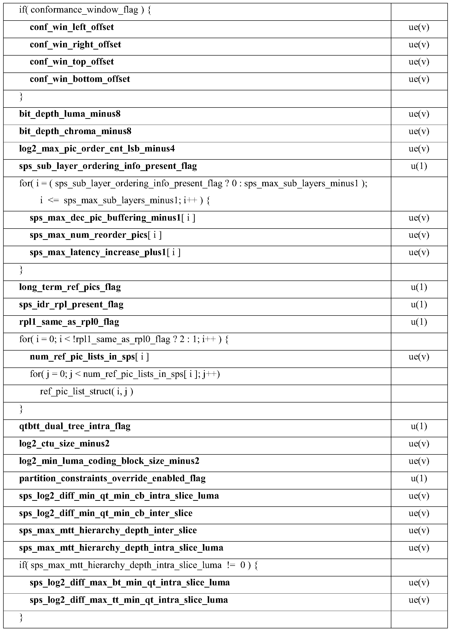


| Category | Condition |
| 1 | c<a and c<b |
| 2 | (c < a &&c==b) || (c == a &&c < b) |
| 3 | (c > a &&c==b) || (c == a &&c > b) |
| 4 | c > a &&c > |
| 5 | None of above |


| Gradient values | Transformation |
| g d2 < g d1 and g h < g v | No transformation |
| g d2 < g d1 and g v < g h | Diagonal |
| g d1 < g d2 and g h < g v | Vertical flip |
| g d1 < g d2 and g v < g h | Rotation |


| condition | r1 | r2 | r3 |
| (y == CtbSizeY-5 || y == CtbSizeY-4) && (applyVirtualBoundary== 1) | 0 | 0 | 0 |
| (y == CtbSizeY-6 || y == CtbSizeY-3) && (applyVirtualBoundary== 1) | 1 | 1 | 1 |
| (y == CtbSizeY-7 || y == CtbSizeY-2) && (applyVirtualBoundary== 1) | 1 | 2 | 2 |
| otherwise | 1 | 2 | 3 |


Claims (75)
- A method of video processing, comprising:determining, for a conversion between a picture of a video that comprises one or more blocks and a bitstream representation of the video, whether a virtual boundary is enabled for a block within the picture for a filtering process based on a rule related to a relationship between a bottom boundary of the block and the picture; andperforming the conversion based on the determining.
- The method of claim 1, wherein the rule defines that the relationship between the bottom boundary of the block and the picture is sufficient for the determining.
- The method of claim 1 or 2, wherein the filtering process comprises an adaptive loop filtering process or an in-loop filtering process.
- The method of any one or more of claims 1 to 3, wherein the rule specifies that the virtual boundary is enabled in case the bottom boundary of the block is not a bottom boundary of the picture.
- The method of any one or more of claims 1 to 3, wherein the rule specifies that the virtual boundary is disabled in case the bottom boundary of the block is a bottom boundary of the picture or is located outside of the picture.
- The method of any one or more of claims 1 to 3, wherein the rule specifies that the virtual boundary is enabled in case the bottom boundary of the block within the picture is not a bottom boundary of the picture.
- The method of any one or more of claims 1 to 3, wherein the rule specifies that the virtual boundary is enabled in case the bottom boundary of the block is not a boundary of a video unit that is smaller than the picture.
- The method of claim 7, wherein the video unit comprises a slice, a tile, or a brick.
- The method of any one or more of claims 1 to 8, wherein the rule specifies that the virtual boundary is enabled in case the bottom boundary of the block is a virtual boundary.
- The method of any one or more of claims 1 to 9, wherein the rule specifies that the virtual boundary is enabled for the filtering process despite that a syntax flag at a picture level indicates that virtual boundary usage is disabled.
- The method of claim 10, wherein the syntax flag comprises pps_loop_filter_across_virtual_boundaries_disabled_flag.
- The method of any one or more of claims 1 to 9, wherein the rule specifies that the virtual boundary is enabled for the filtering process despite that the bottom boundary of the block is same as a bottom boundary of the picture.
- The method of any one or more of claims 1 to 12, wherein, in case the virtual boundary is enabled for the coding tree block, the filtering process filters samples from above the virtual boundary of the block only.
- A method of video processing, comprising:determining, for a conversion between a picture of a video that comprises one or more blocks and a bitstream representation of the video, usage of virtual samples generated based on a padding process associated with a filtering process for a block within the picture based on a rule related to a dimension of the block; andperforming the conversion based on the determining.
- The method of claim 14, wherein the usage of the virtual samples is related to whether a virtual boundary is enabled for the block.
- The method of claim 14 or 15, wherein the filtering process comprises an adaptive loop filtering process or an in-loop filtering process.
- The method of any one or more of claims 14 to 16, wherein the rule specifies that the virtual boundary is always disabled in case the dimension of the block is K×L, K and L being positive integers.
- The method of claim 17, wherein K = L = 4.
- The method of any one or more of claims 14 to 16, wherein the rule specifies that the virtual boundary is always disabled in case the dimension of the block is equal to or smaller than K×L, K and L being positive integers.
- The method of claim 19, wherein K = L = 8.
- The method of any one or more of claims 14 to 16, wherein the rule specifies that the virtual boundary is disabled in case the dimension of the block is M×N, M and N being positive integers.
- The method of claim 21, wherein M = N = 4 or M = N = 8.
- A method of video processing, comprising:determining, for a conversion between a picture of a video that comprises one or more video units and a bitstream representation of the video, to disable usage of samples across boundaries of the one or more video units in a filtering process;wherein the bitstream representation is configured with a syntax flag that indicates that the usage is enabled; andperforming the conversion based on the determining.
- The method of claim 23, wherein the one or more video units comprise a brick or a slice.
- The method of claim 23 or 24, wherein the filtering process comprises an adaptive loop filtering process or an in-loop filtering process.
- The method of any one or more of claims 23 to 25, wherein the syntax flag is not applicable to the adaptive looping filtering process.
- The method of any one or more of claims 23 to 26, wherein the syntax flag comprises loop_filter_across_bricks_enabled_flag or loop_filter_across_slices_enabled_flag.
- The method of any one or more of claims 23 to 27, wherein the syntax flag is applicable to a deblocking filter process or a sample adaptive offset (SAO) process.
- The method of any one or more of claims 23 to 28, wherein the usage of samples comprises usage of virtual samples generated based on a padding process.
- A method of video processing, comprising:determining, for a conversion between a block of a video and a bitstream representation of the video, a unified manner in which a padding process is applied for a filtering process according to a rule, wherein the padding process is applied to generate one or more virtual samples for a sample of the block that is located in proximity to boundaries of different video units; andperforming the conversion based on the determining.
- The method of claim 30, wherein the different video units comprise a slice, a brick, a tile, a picture, or 360-degree video unit.
- The method of claim 30, wherein the boundaries of different video units comprise a virtual boundary or an actual boundary.
- The method of claim 30, wherein the filtering process comprises an adaptive loop filtering process or an in-loop filtering process.
- The method of any one or more of claims 30 to 33, wherein the rule specifies that the padding process is invoked only once for the filtering process.
- The method of any one or more of claims 30 to 34, wherein the rule specifies that the one or more virtual samples are generated based a symmetric padding manner for the in-loop filtering process.
- The method of any one or more of claims 30 to 35, wherein the rule specifies that the padding process is applied in case the sample is located at a bottom boundary of one of the one or more video units.
- The method of any one or more of claims 30 to 36, wherein the rule specifies that a number of lines in which the one or more virtual samples are located is determined based on a second rule related to a location of the sample relative to at least one of the multiple boundaries.
- The method of claim 37, wherein the second rule is related to the location of the sample relative to all of the multiple boundaries.
- The method of claim 37, wherein the sample is located between two boundaries, and the second rule is related to distances between the sample and the two boundaries.
- The method of claim 37, wherein the second rule is related to a distance between the sample and a nearest boundary to the sample.
- The method of any one or more of claims 37 to 40, wherein the number of lines in which the one or more virtual samples are located is determined for each of the multiple boundaries, and a maximum number of lines is used for the conversion.
- The method of any one or more of claims 37 to 41, wherein the number of lines in which the one or more virtual samples are located is determined for each side of the sample along a boundary.
- The method of any one or more of claims 37 to 41, wherein the number of lines in which the one or more virtual samples are located are determined jointly for both sides of the sample along a boundary.
- The method of any one or more of claims 30 to 43, wherein the rule specifies that the filtering process is disabled in case a number of lines in which the one or more virtual samples are located is greater than a threshold.
- The method of claim 44, wherein the filtering process is disabled in case the number of lines on one side of the sample is greater than the threshold.
- The method of claim 44, wherein the filtering process is disabled in case the number of lines is on both sides of the sample is greater than the threshold.
- The method of any one or more of claims 30 to 46, wherein the rule specifies that the one or more virtual samples are located on both sides of the sample in case the adaptive loop filtering process is applied to the block.
- The method of any one or more of claims 30 to 47, wherein the rule specifies that the adaptive loop filtering process is disabled in case the sample is located at a first boundary between a second boundary and a third boundary of the multiple boundaries.
- The method of any one or more of claims 30 to 48, wherein the rule specifies that the padding process is applied in case the sample is located at a bottom boundary of one of the one or more video units and the in-loop filtering process is enabled for the block.
- The method of any one or more of claims 30 to 49, wherein the rule specifies that the padding process is applied in case a condition is satisfied.
- The method of claim 50, wherein the condition is satisfied in case the sample is located at a bottom boundary of one of the one or more video units and a syntax flag indicates that usage of samples across boundaries of the one or more video units in the filtering process is disallowed.
- The method of claim 51, wherein the syntax flag comprises pps_loop_filter_across_virtual_boundaries_disabled_flag or loop_filter_across_slices_enabled_flag/loop_filter_across_slices_enabled_flag.
- A method of video processing, comprising:determining, for a conversion between a block of a video and a bitstream representation of the video, a number of lines for which a padding process is applied in a filtering process according to a rule, wherein the padding process is applied to generate one or more virtual samples for a sample of the block that is located in proximity to at least two boundaries, the at least two boundaries comprising a virtual boundary and at least one other boundary, and wherein the rule is related to distances between the sample and the at least two boundaries; andperforming the conversion based on the determining.
- The method of claim 53, wherein the filter process comprises an adaptive loop filtering process.
- The method of claim 53 or 54, wherein the rule specifies that the number of lines for each side of the sample is (M -min (D0, D1) ) , wherein D0 represents a first distance between the sample and the virtual boundary and D1 represents a second distance between the sample and the at least one other boundary, and wherein M represents a number of lines from the virtual boundary to a bottom boundary of the block.
- The method of claim 53 or 54, wherein the rule specifies that the number of lines for each side of the sample is (M -max (D0, D1) ) , wherein D0 represents a first distance between the sample and the virtual boundary and D1 represents a second distance between the sample and the at least one other boundary, and wherein M represents a number of lines from the virtual boundary to a bottom boundary of the block.
- A method of video processing, comprising:determining, for a conversion between a block of a video of a video unit and a bitstream representation of the video, (1) a first manner of selecting a first sample prior to applying one or more in-loop filtering process and (2) a second manner of selecting a second sample after applying the one or more in-loop filtering process and prior to applying an adaptive filtering process; andperforming the conversion based on the determining.
- The method of claim 57, wherein the video unit comprises a coding tree block, a slice, or a brick.
- The method of claim 57 or 58, wherein the first manner of selecting the first sample and the second manner of selecting the second sample are based on locations of the first sample and the second sample.
- The method of claim 59, wherein the first manner specifies that a sample located at bottom boundary of the video unit is selected as the first sample in case the sample is used in the adaptive filtering process.
- The method of claim 59, wherein the second manner specifies that a sample not located at bottom boundary of the video unit is selected as the second sample in case the sample is used in the adaptive filtering process.
- A method of video processing, comprising:determining, for a conversion between a block of a video of a video unit and a bitstream representation of the video, an order of applying multiple padding processes to generate one or more virtual samples for a sample of the block for a filtering process; andperforming the conversion based on the determining.
- The method of claim 62, wherein the block comprises a coding tree unit or a virtual pipeline data unit.
- The method of claim 62, wherein the video unit comprises a slice, a brick, or a sub-region of a picture.
- The method of any one or more of claims 62 to 64, wherein the order specifies that a first padding process of the video unit is applied before a second padding process for virtual boundaries.
- The method of claim 65, wherein a first set of virtual samples along a single side of a sample of the block is generated in the first padding process.
- The method of claim 66, wherein a second set of virtual samples along both sides of a sample of the block is generated in the second padding process.
- The method of claim 64 or 65, wherein the first set of virtual samples is used in the second padding process to generate the second set of virtual samples.
- The method of any one or more of claims 1 to 66, wherein a boundary comprises a horizontal boundary between two regions within the picture.
- The method of any one or more of claims 1 to 66, wherein a boundary comprises a vertical boundary between two regions within the picture.
- The method of 69 or 70, wherein the two regions comprise a sub-picture of the video.
- The method of any one or more of claims 1 to 71, wherein the conversion includes encoding the video into the bitstream representation.
- The method of any one or more of claims 1 to 71, wherein the conversion includes decoding the bitstream representation into the video.
- A video processing apparatus comprising a processor configured to implement a method recited in any one or more of claims 1 to 73.
- A computer-readable medium having code stored thereon, the code, upon execution by a processor, causing the processor to implement a method recited in any one or more of claims 1 to 73.
Priority Applications (9)
| Application Number | Priority Date | Filing Date | Title |
|---|---|---|---|
| EP20822936.9A EP3970366B1 (en) | 2019-06-14 | 2020-06-15 | Handling video unit boundaries and virtual boundaries |
| BR112021024638-0A BR112021024638B1 (en) | 2019-06-14 | 2020-06-15 | APPARATUS FOR PROCESSING VIDEO DATA, METHOD, RELATED STORAGE AND RECORDING MEDIA |
| CN202080043857.5A CN114424539B (en) | 2019-06-14 | 2020-06-15 | Handling video unit borders and virtual borders |
| CN202311587522.1A CN118138754A (en) | 2019-06-14 | 2020-06-15 | Handling video unit borders and virtual borders |
| JP2021573862A JP7433346B2 (en) | 2019-06-14 | 2020-06-15 | Handling video unit boundaries and virtual boundaries |
| KR1020217039968A KR20220020268A (en) | 2019-06-14 | 2020-06-15 | Processing of Video Unit Boundaries and Virtual Boundaries |
| US17/548,187 US12003712B2 (en) | 2019-06-14 | 2021-12-10 | Handling video unit boundaries and virtual boundaries |
| US18/516,577 US12526407B2 (en) | 2019-06-14 | 2023-11-21 | Handling video unit boundaries and virtual boundaries |
| US19/404,382 US20260089320A1 (en) | 2019-06-14 | 2025-12-01 | Handling video unit boundaries and virtual boundaries |
Applications Claiming Priority (6)
| Application Number | Priority Date | Filing Date | Title |
|---|---|---|---|
| CNPCT/CN2019/091324 | 2019-06-14 | ||
| CN2019091324 | 2019-06-14 | ||
| CN2019092861 | 2019-06-25 | ||
| CNPCT/CN2019/092861 | 2019-06-25 | ||
| CN2019095157 | 2019-07-08 | ||
| CNPCT/CN2019/095157 | 2019-07-08 |
Related Child Applications (1)
| Application Number | Title | Priority Date | Filing Date |
|---|---|---|---|
| US17/548,187 Continuation US12003712B2 (en) | 2019-06-14 | 2021-12-10 | Handling video unit boundaries and virtual boundaries |
Publications (1)
| Publication Number | Publication Date |
|---|---|
| WO2020249123A1 true WO2020249123A1 (en) | 2020-12-17 |
Family
ID=73781981
Family Applications (1)
| Application Number | Title | Priority Date | Filing Date |
|---|---|---|---|
| PCT/CN2020/096044 Ceased WO2020249123A1 (en) | 2019-06-14 | 2020-06-15 | Handling video unit boundaries and virtual boundaries |
Country Status (6)
| Country | Link |
|---|---|
| US (3) | US12003712B2 (en) |
| EP (1) | EP3970366B1 (en) |
| JP (1) | JP7433346B2 (en) |
| KR (1) | KR20220020268A (en) |
| CN (2) | CN118138754A (en) |
| WO (1) | WO2020249123A1 (en) |
Cited By (4)
| Publication number | Priority date | Publication date | Assignee | Title |
|---|---|---|---|---|
| WO2021133236A1 (en) * | 2019-12-24 | 2021-07-01 | Telefonaktiebolaget Lm Ericsson (Publ) | Virtual boundary processing for adaptive loop filtering |
| JP2023502131A (en) * | 2019-11-18 | 2023-01-20 | エルジー エレクトロニクス インコーポレイティド | Image coding apparatus and method for controlling loop filtering |
| JP2023502128A (en) * | 2019-11-18 | 2023-01-20 | エルジー エレクトロニクス インコーポレイティド | Image coding apparatus and method for controlling loop filtering |
| JP2023503070A (en) * | 2019-11-18 | 2023-01-26 | エルジー エレクトロニクス インコーポレイティド | Image coding apparatus and method based on filtering |
Families Citing this family (15)
| Publication number | Priority date | Publication date | Assignee | Title |
|---|---|---|---|---|
| WO2020233660A1 (en) | 2019-05-21 | 2020-11-26 | Beijing Bytedance Network Technology Co., Ltd. | Syntax-based motion candidate derivation in sub-block merge mode |
| CN113994671B (en) | 2019-06-14 | 2024-05-10 | 北京字节跳动网络技术有限公司 | Processing video cell boundaries and virtual boundaries based on color formats |
| EP3970366B1 (en) | 2019-06-14 | 2025-12-10 | Beijing Bytedance Network Technology Co., Ltd. | Handling video unit boundaries and virtual boundaries |
| CN117478878A (en) | 2019-07-09 | 2024-01-30 | 北京字节跳动网络技术有限公司 | Sample point determination for adaptive loop filtering |
| EP3984223A4 (en) | 2019-07-11 | 2022-11-09 | Beijing Bytedance Network Technology Co., Ltd. | SAMPLE FILLING IN ADAPTIVE LOOP FILTERING |
| CN117676168A (en) | 2019-07-15 | 2024-03-08 | 北京字节跳动网络技术有限公司 | Classification in adaptive loop filtering |
| US11641465B2 (en) * | 2019-07-25 | 2023-05-02 | Hfi Innovation Inc. | Method and apparatus of cross-component adaptive loop filtering with virtual boundary for video coding |
| CN120956931A (en) * | 2019-09-06 | 2025-11-14 | 松下电器(美国)知识产权公司 | Encoding device, decoding device and bit stream storage method |
| CN117278747A (en) | 2019-09-22 | 2023-12-22 | 北京字节跳动网络技术有限公司 | Filling process in adaptive loop filtering |
| KR102721536B1 (en) | 2019-09-27 | 2024-10-25 | 베이징 바이트댄스 네트워크 테크놀로지 컴퍼니, 리미티드 | Adaptive loop filtering between different video units |
| JP7454042B2 (en) | 2019-10-10 | 2024-03-21 | 北京字節跳動網絡技術有限公司 | Padding process at unavailable sample positions in adaptive loop filtering |
| KR20220157950A (en) | 2020-03-23 | 2022-11-29 | 베이징 바이트댄스 네트워크 테크놀로지 컴퍼니, 리미티드 | Prediction refinement for affine merge and affine motion vector prediction modes |
| US12309433B2 (en) * | 2021-05-20 | 2025-05-20 | Lemon Inc. | On padding methods for neural network-based in-loop filter |
| US12368879B2 (en) * | 2022-03-25 | 2025-07-22 | Tencent America LLC | Method and apparatus adaptive constraint on bi-prediction for out-of-boundary conditions |
| EP4730781A1 (en) * | 2024-10-17 | 2026-04-22 | InterDigital CE Patent Holdings, SAS | Reuse of loop filter control information from reference frames |
Citations (5)
| Publication number | Priority date | Publication date | Assignee | Title |
|---|---|---|---|---|
| CN103503456A (en) * | 2011-05-10 | 2014-01-08 | 联发科技股份有限公司 | Method and device for reducing in-loop filter buffer |
| CN105847843A (en) * | 2015-02-02 | 2016-08-10 | 联发科技股份有限公司 | Multi-standard video coder with novel intra-prediction decoding |
| WO2018119429A1 (en) * | 2016-12-22 | 2018-06-28 | Qualcomm Incorporated | Deriving bilateral filter information based on a prediction mode in video decoding |
| CN109600611A (en) * | 2018-11-09 | 2019-04-09 | 北京达佳互联信息技术有限公司 | Loop circuit filtering method, loop filter, electronic equipment and readable medium |
| CN109660797A (en) * | 2018-11-09 | 2019-04-19 | 北京达佳互联信息技术有限公司 | Adaptive filter method, device, electronic equipment and computer-readable medium |
Family Cites Families (144)
| Publication number | Priority date | Publication date | Assignee | Title |
|---|---|---|---|---|
| RU2154918C1 (en) * | 1998-08-01 | 2000-08-20 | Самсунг Электроникс Ко., Лтд. | Method and device for loop filtration of image data |
| US7558320B2 (en) * | 2003-06-13 | 2009-07-07 | Microsoft Corporation | Quality control in frame interpolation with motion analysis |
| CN101207812B (en) | 2007-12-10 | 2010-04-07 | 海信集团有限公司 | A video loop filtering method |
| US10123050B2 (en) | 2008-07-11 | 2018-11-06 | Qualcomm Incorporated | Filtering video data using a plurality of filters |
| CN102349107B (en) | 2009-02-10 | 2015-02-18 | 晶像股份有限公司 | Block noise detection and filtering |
| CN105872554A (en) | 2010-03-09 | 2016-08-17 | 汤姆森特许公司 | Methods and apparatus for classification-based loop filter |
| US9094658B2 (en) | 2010-05-10 | 2015-07-28 | Mediatek Inc. | Method and apparatus of adaptive loop filtering |
| EP2388999B1 (en) | 2010-05-17 | 2021-02-24 | Lg Electronics Inc. | New intra prediction modes |
| MX338462B (en) | 2010-09-30 | 2016-04-15 | Mitsubishi Electric Corp | Motion-video encoding apparatus, motion-video decoding apparatus, motion-video encoding method, and motion-video decoding method. |
| US8861617B2 (en) | 2010-10-05 | 2014-10-14 | Mediatek Inc | Method and apparatus of region-based adaptive loop filtering |
| US9055305B2 (en) | 2011-01-09 | 2015-06-09 | Mediatek Inc. | Apparatus and method of sample adaptive offset for video coding |
| WO2012045269A1 (en) | 2010-10-05 | 2012-04-12 | Mediatek Inc. | Method and apparatus of region-based adaptive loop filtering |
| US9525884B2 (en) | 2010-11-02 | 2016-12-20 | Hfi Innovation Inc. | Method and apparatus of slice boundary filtering for high efficiency video coding |
| KR101956284B1 (en) | 2011-06-30 | 2019-03-08 | 엘지전자 주식회사 | Interpolation Method And Prediction method thereof |
| US9641866B2 (en) | 2011-08-18 | 2017-05-02 | Qualcomm Incorporated | Applying partition-based filters |
| US9357235B2 (en) | 2011-10-13 | 2016-05-31 | Qualcomm Incorporated | Sample adaptive offset merged with adaptive loop filter in video coding |
| CN103891292B (en) | 2011-10-24 | 2018-02-02 | 寰发股份有限公司 | Video data loop filtering processing method and device |
| US9247258B2 (en) | 2011-10-26 | 2016-01-26 | Qualcomm Incorporated | Unified design for picture partitioning schemes |
| US20130107973A1 (en) | 2011-10-28 | 2013-05-02 | Qualcomm Incorporated | Loop filtering control over tile boundaries |
| US9077998B2 (en) | 2011-11-04 | 2015-07-07 | Qualcomm Incorporated | Padding of segments in coded slice NAL units |
| US20130128986A1 (en) | 2011-11-23 | 2013-05-23 | Mediatek Inc. | Method and Apparatus of Slice Boundary Padding for Loop Filtering |
| US9538200B2 (en) | 2012-01-19 | 2017-01-03 | Qualcomm Incorporated | Signaling of deblocking filter parameters in video coding |
| US9591331B2 (en) | 2012-03-28 | 2017-03-07 | Qualcomm Incorporated | Merge signaling and loop filter on/off signaling |
| US8983218B2 (en) | 2012-04-11 | 2015-03-17 | Texas Instruments Incorporated | Virtual boundary processing simplification for adaptive loop filtering (ALF) in video coding |
| AU2013248857B2 (en) | 2012-04-16 | 2015-11-05 | Hfi Innovation Inc. | Method and apparatus for loop filtering across slice or tile boundaries |
| US20130343447A1 (en) | 2012-06-25 | 2013-12-26 | Broadcom Corporation | Adaptive loop filter (ALF) padding in accordance with video coding |
| KR102070622B1 (en) | 2012-11-23 | 2020-01-29 | 삼성전자주식회사 | Method and apparatus for estimating a quantization table for a video image |
| US9596461B2 (en) | 2012-11-26 | 2017-03-14 | Qualcomm Incorporated | Loop filtering across constrained intra block boundaries in video coding |
| US10321130B2 (en) | 2013-01-07 | 2019-06-11 | Vid Scale, Inc. | Enhanced deblocking filters for video coding |
| US9467707B2 (en) | 2013-03-05 | 2016-10-11 | Qualcomm Incorporated | Parallel processing for video coding |
| RU2639958C2 (en) | 2013-04-17 | 2017-12-25 | Нокиа Текнолоджиз Ой | Device, method and computer program for coding and decoding videoinformation |
| US9648335B2 (en) | 2013-07-12 | 2017-05-09 | Qualcomm Incorporated | Bitstream restrictions on picture partitions across layers |
| US9578328B2 (en) | 2013-07-15 | 2017-02-21 | Qualcomm Incorporated | Cross-layer parallel processing and offset delay parameters for video coding |
| GB2516824A (en) | 2013-07-23 | 2015-02-11 | Nokia Corp | An apparatus, a method and a computer program for video coding and decoding |
| US20150071357A1 (en) | 2013-09-12 | 2015-03-12 | Qualcomm Incorporated | Partial intra block copying for video coding |
| JP6866157B2 (en) | 2013-09-27 | 2021-04-28 | クゥアルコム・インコーポレイテッドQualcomm Incorporated | Residual coding for depth intra prediction mode |
| EP3069511A4 (en) | 2013-11-15 | 2017-09-27 | MediaTek Inc. | Method of block-based adaptive loop filtering |
| KR102355224B1 (en) | 2014-03-16 | 2022-01-25 | 브이아이디 스케일, 인크. | Method and apparatus for the signaling of lossless video coding |
| US9807406B2 (en) | 2014-03-17 | 2017-10-31 | Qualcomm Incorporated | Picture flushing and decoded picture buffer parameter inference for multi-layer bitstreams |
| KR102298599B1 (en) | 2014-04-29 | 2021-09-03 | 마이크로소프트 테크놀로지 라이센싱, 엘엘씨 | Encoder-side decisions for sample adaptive offset filtering |
| EP3198867A4 (en) | 2014-10-31 | 2018-04-04 | MediaTek Inc. | Method of improved directional intra prediction for video coding |
| US9591325B2 (en) | 2015-01-27 | 2017-03-07 | Microsoft Technology Licensing, Llc | Special case handling for merged chroma blocks in intra block copy prediction mode |
| US10158836B2 (en) | 2015-01-30 | 2018-12-18 | Qualcomm Incorporated | Clipping for cross-component prediction and adaptive color transform for video coding |
| US10057574B2 (en) | 2015-02-11 | 2018-08-21 | Qualcomm Incorporated | Coding tree unit (CTU) level adaptive loop filter (ALF) |
| US20160241881A1 (en) | 2015-02-13 | 2016-08-18 | Mediatek Inc. | Method and Apparatus of Loop Filters for Efficient Hardware Implementation |
| US20180115787A1 (en) | 2015-04-12 | 2018-04-26 | Lg Electronics Inc. | Method for encoding and decoding video signal, and apparatus therefor |
| EP4040791A1 (en) | 2015-06-08 | 2022-08-10 | Vid Scale, Inc. | Intra block copy mode for screen content coding |
| US10887597B2 (en) | 2015-06-09 | 2021-01-05 | Qualcomm Incorporated | Systems and methods of determining illumination compensation parameters for video coding |
| WO2017045101A1 (en) | 2015-09-14 | 2017-03-23 | Mediatek Singapore Pte. Ltd. | Advanced deblocking filter in video coding |
| CN108293136B (en) | 2015-09-23 | 2022-12-30 | 诺基亚技术有限公司 | Method, apparatus and computer-readable storage medium for encoding 360-degree panoramic video |
| US10531111B2 (en) | 2015-11-06 | 2020-01-07 | Microsoft Technology Licensing, Llc | Flexible reference picture management for video encoding and decoding |
| WO2017082670A1 (en) | 2015-11-12 | 2017-05-18 | 엘지전자 주식회사 | Method and apparatus for coefficient induced intra prediction in image coding system |
| KR102345475B1 (en) | 2016-01-05 | 2022-01-03 | 한국전자통신연구원 | Method and apparatus for prediction of residual signal |
| WO2017133660A1 (en) | 2016-02-04 | 2017-08-10 | Mediatek Inc. | Method and apparatus of non-local adaptive in-loop filters in video coding |
| US11405611B2 (en) | 2016-02-15 | 2022-08-02 | Qualcomm Incorporated | Predicting filter coefficients from fixed filters for video coding |
| CN116962721A (en) | 2016-05-04 | 2023-10-27 | 微软技术许可有限责任公司 | Method for intra-picture prediction using non-adjacent reference lines of sample values |
| US10419755B2 (en) | 2016-05-16 | 2019-09-17 | Qualcomm Incorporated | Confusion of multiple filters in adaptive loop filtering in video coding |
| US10264282B2 (en) * | 2016-06-27 | 2019-04-16 | Mediatek Inc. | Method and apparatus of inter coding for VR video using virtual reference frames |
| KR102882879B1 (en) | 2016-07-08 | 2025-11-06 | 인터디지털 브이씨 홀딩스 인코포레이티드 | 360-degree video coding using geometry projection |
| US10841581B2 (en) | 2016-07-14 | 2020-11-17 | Arris Enterprises Llc | Region specific encoding and SAO-sensitive-slice-width-adaptation for improved-quality HEVC encoding |
| WO2018026166A1 (en) | 2016-08-01 | 2018-02-08 | 한국전자통신연구원 | Image encoding/decoding method and apparatus, and recording medium storing bitstream |
| US20180041778A1 (en) | 2016-08-02 | 2018-02-08 | Qualcomm Incorporated | Geometry transformation-based adaptive loop filtering |
| WO2018026219A1 (en) | 2016-08-03 | 2018-02-08 | 주식회사 케이티 | Video signal processing method and device |
| US20180048907A1 (en) | 2016-08-11 | 2018-02-15 | Qualcomm Incorporated | Video coding tools for in-loop sample processing |
| US20180054613A1 (en) | 2016-08-22 | 2018-02-22 | Mediatek Inc. | Video encoding method and apparatus with in-loop filtering process not applied to reconstructed blocks located at image content discontinuity edge and associated video decoding method and apparatus |
| US10419757B2 (en) | 2016-08-31 | 2019-09-17 | Qualcomm Incorporated | Cross-component filter |
| WO2018052224A1 (en) | 2016-09-13 | 2018-03-22 | 한국전자통신연구원 | Video encoding/decoding method and device, and recording medium having bitstream stored therein |
| US10382781B2 (en) | 2016-09-28 | 2019-08-13 | Qualcomm Incorporated | Interpolation filters for intra prediction in video coding |
| US10623737B2 (en) | 2016-10-04 | 2020-04-14 | Qualcomm Incorporated | Peak sample adaptive offset |
| KR20180057566A (en) | 2016-11-22 | 2018-05-30 | 한국전자통신연구원 | Method and apparatus for encoding/decoding image and recording medium for storing bitstream |
| CN108111851B (en) | 2016-11-25 | 2020-12-22 | 华为技术有限公司 | A kind of deblocking filtering method and terminal |
| US20180184127A1 (en) | 2016-12-22 | 2018-06-28 | Qualcomm Incorporated | Determining neighboring samples for bilateral filtering in video coding |
| US20180192074A1 (en) | 2017-01-03 | 2018-07-05 | Mediatek Inc. | Video processing method for processing projection-based frame with 360-degree content represented by projection faces packed in 360-degree virtual reality projection layout |
| US10506230B2 (en) | 2017-01-04 | 2019-12-10 | Qualcomm Incorporated | Modified adaptive loop filter temporal prediction for temporal scalability support |
| US11277635B2 (en) | 2017-03-17 | 2022-03-15 | Vid Scale, Inc. | Predictive coding for 360-degree video based on geometry padding |
| EP3979639A1 (en) | 2017-03-22 | 2022-04-06 | Industry-University Cooperation Foundation Hanyang University | Tile partitions |
| US11212497B2 (en) | 2017-03-30 | 2021-12-28 | Samsung Electronics Co., Ltd. | Method and apparatus for producing 360 degree image content on rectangular projection by selectively applying in-loop filter |
| KR20230079466A (en) | 2017-04-11 | 2023-06-07 | 브이아이디 스케일, 인크. | 360-degree video coding using face continuities |
| US10778974B2 (en) | 2017-07-05 | 2020-09-15 | Qualcomm Incorporated | Adaptive loop filter with enhanced classification methods |
| US20190044809A1 (en) | 2017-08-30 | 2019-02-07 | Intel Corporation | Technologies for managing a flexible host interface of a network interface controller |
| EP3454556A1 (en) | 2017-09-08 | 2019-03-13 | Thomson Licensing | Method and apparatus for video encoding and decoding using pattern-based block filtering |
| US10728573B2 (en) | 2017-09-08 | 2020-07-28 | Qualcomm Incorporated | Motion compensated boundary pixel padding |
| US11418816B2 (en) | 2017-09-20 | 2022-08-16 | Vid Scale, Inc. | Handling face discontinuities in 360-degree video coding |
| US10965941B2 (en) | 2017-10-09 | 2021-03-30 | Qualcomm Incorporated | Position-dependent prediction combinations in video coding |
| CN114979635B (en) | 2017-10-09 | 2023-10-27 | 佳能株式会社 | Method, apparatus and storage medium for filtering a sample block |
| JP2021016016A (en) | 2017-10-20 | 2021-02-12 | シャープ株式会社 | Video encoding device and video decoding device |
| WO2019089864A1 (en) | 2017-11-01 | 2019-05-09 | Vid Scale, Inc. | Overlapped block motion compensation |
| EP4676052A3 (en) | 2017-11-01 | 2026-03-25 | InterDigital VC Holdings, Inc. | Methods for simplifying adaptive loop filter in video coding |
| US10728549B2 (en) | 2017-11-06 | 2020-07-28 | Dolby Laboratories Licensing Corporation | Adaptive loop filtering for high-dynamic range video |
| CN107801024B (en) | 2017-11-09 | 2019-07-12 | 北京大学深圳研究生院 | A Boundary Filtering Method for Intra Prediction |
| US10721469B2 (en) | 2017-11-28 | 2020-07-21 | Qualcomm Incorporated | Line buffer reduction for adaptive loop filtering in video coding |
| EP3720129A4 (en) | 2017-11-29 | 2021-08-25 | Electronics and Telecommunications Research Institute | METHOD AND DEVICE FOR CODING / DECODING IMAGES USING LOOP FILTERING |
| US11432010B2 (en) | 2017-12-19 | 2022-08-30 | Vid Scale, Inc. | Face discontinuity filtering for 360-degree video coding |
| WO2019131400A1 (en) | 2017-12-26 | 2019-07-04 | シャープ株式会社 | Image filter device, image decoding device, and image encoding device |
| US11259021B2 (en) | 2017-12-29 | 2022-02-22 | Sharp Kabushiki Kaisha | Systems and methods for partitioning video blocks at a boundary of a picture for video coding |
| CN109996069B (en) | 2018-01-03 | 2021-12-10 | 华为技术有限公司 | Video image coding and decoding method and device |
| US20190215518A1 (en) | 2018-01-10 | 2019-07-11 | Qualcomm Incorporated | Histogram of gradient based optical flow |
| US10972729B2 (en) | 2018-01-20 | 2021-04-06 | Qualcomm Incorporated | Deblocking filter selection and application in video coding |
| US20190238845A1 (en) | 2018-01-26 | 2019-08-01 | Qualcomm Incorporated | Adaptive loop filtering on deblocking filter results in video coding |
| CN110337811A (en) | 2018-02-14 | 2019-10-15 | 北京大学 | Method, device and computer system for motion compensation |
| US11212438B2 (en) | 2018-02-14 | 2021-12-28 | Qualcomm Incorporated | Loop filter padding for 360-degree video coding |
| US20190281273A1 (en) | 2018-03-08 | 2019-09-12 | Mediatek Inc. | Adaptive loop filtering method for reconstructed projection-based frame that employs projection layout of 360-degree virtual reality projection |
| CN108449591A (en) | 2018-03-21 | 2018-08-24 | 天津大学 | A method for simplification of deep video DMM mode |
| US11470359B2 (en) | 2018-03-30 | 2022-10-11 | Sharp Kabushiki Kaisha | Systems and methods for partitioning video blocks at a boundary of a picture for video coding |
| US10708592B2 (en) | 2018-04-02 | 2020-07-07 | Qualcomm Incorporated | Deblocking filter for video coding and processing |
| US20190306502A1 (en) | 2018-04-02 | 2019-10-03 | Qualcomm Incorporated | System and method for improved adaptive loop filtering |
| WO2019208372A1 (en) | 2018-04-25 | 2019-10-31 | パナソニック インテレクチュアル プロパティ コーポレーション オブ アメリカ | Encoding device, decoding device, encoding method, and decoding method |
| US10904576B2 (en) | 2018-04-27 | 2021-01-26 | Panasonic Intellectual Property Corporation Of America | Encoder, decoder, encoding method, and decoding method for generating a prediction image using a plurality of pixels generated outside of a boundary of a reference picture on which smoothing has been performed |
| CN118660162A (en) | 2018-05-31 | 2024-09-17 | 夏普株式会社 | Video data decoding device, video data encoding device and method |
| US11451773B2 (en) | 2018-06-01 | 2022-09-20 | Qualcomm Incorporated | Block-based adaptive loop filter (ALF) design and signaling |
| US11368677B2 (en) | 2018-06-18 | 2022-06-21 | Interdigital Vc Holdings, Inc. | Boundary filtering for planar and DC modes in intra prediction |
| CN111819847B (en) | 2018-06-21 | 2022-08-09 | 瑞典爱立信有限公司 | Video picture boundary encoding method, video picture boundary decoding method, codec and storage medium |
| CN112335250A (en) | 2018-06-28 | 2021-02-05 | 韩国电子通信研究院 | Method and apparatus for encoding/decoding image and recording medium for storing bitstream |
| WO2020009514A1 (en) | 2018-07-06 | 2020-01-09 | 한국전자통신연구원 | Image encoding/decoding method and device, and recording medium in which bitstream is stored |
| WO2020043192A1 (en) | 2018-08-31 | 2020-03-05 | Mediatek Inc. | Method and apparatus of in-loop filtering for virtual boundaries in video coding |
| FI3847817T3 (en) | 2018-09-14 | 2024-06-26 | Huawei Tech Co Ltd | Slicing and tiling in video coding |
| CN113287316B (en) | 2018-10-23 | 2023-07-21 | 寰发股份有限公司 | Method and device for reducing loop filter buffer |
| CN112913247B (en) | 2018-10-23 | 2023-04-28 | 北京字节跳动网络技术有限公司 | Video processing using local illumination compensation |
| US11044473B2 (en) * | 2018-12-21 | 2021-06-22 | Qualcomm Incorporated | Adaptive loop filtering classification in video coding |
| KR20250107970A (en) | 2018-12-23 | 2025-07-14 | 후아웨이 테크놀러지 컴퍼니 리미티드 | An encoder, a decoder and corresponding methods using an adaptive loop filter |
| PL4221213T3 (en) | 2019-01-09 | 2024-11-18 | Huawei Technologies Co., Ltd. | A video encoder, a video decoder and corresponding methods |
| WO2020143824A1 (en) | 2019-01-13 | 2020-07-16 | Beijing Bytedance Network Technology Co., Ltd. | Interaction between lut and shared merge list |
| KR20240058982A (en) | 2019-02-27 | 2024-05-03 | 후아웨이 테크놀러지 컴퍼니 리미티드 | An encoder, a decoder and corresponding methods |
| KR20210130735A (en) | 2019-03-02 | 2021-11-01 | 베이징 바이트댄스 네트워크 테크놀로지 컴퍼니, 리미티드 | Restrictions on in-loop filtering |
| KR102825177B1 (en) | 2019-03-11 | 2025-06-26 | 후아웨이 테크놀러지 컴퍼니 리미티드 | Encoders, decoders, and corresponding methods |
| US11910024B2 (en) | 2019-03-11 | 2024-02-20 | Qualcomm Incorporated | Boundary handling for adaptive loop filtering |
| CN117499644A (en) | 2019-03-14 | 2024-02-02 | 北京字节跳动网络技术有限公司 | Signaling and syntax of loop shaping information |
| WO2020192645A1 (en) | 2019-03-24 | 2020-10-01 | Beijing Bytedance Network Technology Co., Ltd. | Multi-parameter adaptive loop filtering in video processing |
| US11546587B2 (en) | 2019-04-11 | 2023-01-03 | Mediatek Inc. | Adaptive loop filter with adaptive parameter set |
| WO2020211770A1 (en) | 2019-04-15 | 2020-10-22 | Beijing Bytedance Network Technology Co., Ltd. | Temporal prediction of parameters in non-linear adaptive loop filter |
| WO2020211810A1 (en) | 2019-04-16 | 2020-10-22 | Beijing Bytedance Network Technology Co., Ltd. | On adaptive loop filtering for video coding |
| EP3970366B1 (en) | 2019-06-14 | 2025-12-10 | Beijing Bytedance Network Technology Co., Ltd. | Handling video unit boundaries and virtual boundaries |
| CN113994671B (en) | 2019-06-14 | 2024-05-10 | 北京字节跳动网络技术有限公司 | Processing video cell boundaries and virtual boundaries based on color formats |
| CN117478878A (en) | 2019-07-09 | 2024-01-30 | 北京字节跳动网络技术有限公司 | Sample point determination for adaptive loop filtering |
| EP3998772A4 (en) | 2019-07-11 | 2023-06-07 | Samsung Electronics Co., Ltd. | VIDEO DECODING METHOD AND APPARATUS, AND VIDEO CODING METHOD AND APPARATUS |
| EP3984223A4 (en) | 2019-07-11 | 2022-11-09 | Beijing Bytedance Network Technology Co., Ltd. | SAMPLE FILLING IN ADAPTIVE LOOP FILTERING |
| US11432015B2 (en) | 2019-07-11 | 2022-08-30 | Qualcomm Incorporated | Adaptive loop filtering across raster-scan slices |
| CN117676168A (en) | 2019-07-15 | 2024-03-08 | 北京字节跳动网络技术有限公司 | Classification in adaptive loop filtering |
| US11303890B2 (en) | 2019-09-05 | 2022-04-12 | Qualcomm Incorporated | Reusing adaptive loop filter (ALF) sub-picture boundary processing for raster-scan slice boundaries |
| CN114731419B (en) | 2019-09-05 | 2025-08-22 | 寰发股份有限公司 | Video encoding and decoding method and device |
| CN117278747A (en) | 2019-09-22 | 2023-12-22 | 北京字节跳动网络技术有限公司 | Filling process in adaptive loop filtering |
| KR102721536B1 (en) | 2019-09-27 | 2024-10-25 | 베이징 바이트댄스 네트워크 테크놀로지 컴퍼니, 리미티드 | Adaptive loop filtering between different video units |
| JP7454042B2 (en) | 2019-10-10 | 2024-03-21 | 北京字節跳動網絡技術有限公司 | Padding process at unavailable sample positions in adaptive loop filtering |
| US11115530B1 (en) | 2020-06-23 | 2021-09-07 | Bank Of America Corporation | Integration of human agent and automated tools for interactive voice response (IVR) systems |
-
2020
- 2020-06-15 EP EP20822936.9A patent/EP3970366B1/en active Active
- 2020-06-15 CN CN202311587522.1A patent/CN118138754A/en active Pending
- 2020-06-15 JP JP2021573862A patent/JP7433346B2/en active Active
- 2020-06-15 WO PCT/CN2020/096044 patent/WO2020249123A1/en not_active Ceased
- 2020-06-15 KR KR1020217039968A patent/KR20220020268A/en not_active Ceased
- 2020-06-15 CN CN202080043857.5A patent/CN114424539B/en active Active
-
2021
- 2021-12-10 US US17/548,187 patent/US12003712B2/en active Active
-
2023
- 2023-11-21 US US18/516,577 patent/US12526407B2/en active Active
-
2025
- 2025-12-01 US US19/404,382 patent/US20260089320A1/en active Pending
Patent Citations (5)
| Publication number | Priority date | Publication date | Assignee | Title |
|---|---|---|---|---|
| CN103503456A (en) * | 2011-05-10 | 2014-01-08 | 联发科技股份有限公司 | Method and device for reducing in-loop filter buffer |
| CN105847843A (en) * | 2015-02-02 | 2016-08-10 | 联发科技股份有限公司 | Multi-standard video coder with novel intra-prediction decoding |
| WO2018119429A1 (en) * | 2016-12-22 | 2018-06-28 | Qualcomm Incorporated | Deriving bilateral filter information based on a prediction mode in video decoding |
| CN109600611A (en) * | 2018-11-09 | 2019-04-09 | 北京达佳互联信息技术有限公司 | Loop circuit filtering method, loop filter, electronic equipment and readable medium |
| CN109660797A (en) * | 2018-11-09 | 2019-04-19 | 北京达佳互联信息技术有限公司 | Adaptive filter method, device, electronic equipment and computer-readable medium |
Non-Patent Citations (6)
| Title |
|---|
| ANAND MEHER KOTRA ET AL., CE5-2: LOOP FILTER LINE BUFFER REDUCTION |
| BENJAMIN BROSS ET AL., VERSATILE VIDEO CODING (DRAFT 5 |
| CHEN,CHING-YEH ET AL.: "CE5-1: Adaptive loop filter with virtual boundary processing", JOINT VIDEO EXPERTS TEAM (JVET) OF ITU-T SG 16 WP 3 AND ISO/IEC JTC 1/SC 29/WG 11, 27 March 2019 (2019-03-27), XP030203267 * |
| CHING-YEH CHEN ET AL., NON-CE8.C.7: SINGLE-SOURCE SAO AND ALF VIRTUAL BOUNDARY PROCESSING WITH CROSS9X9 |
| PARK,MINSOO ET AL.: "CE4: Results on Reference picture boundary padding in J0025", JOINT VIDEO EXPERTS TEAM (JVET) OF ITU-T SG 16 WP 3 AND ISO/IEC JTC 1/SC 29/WG 11, 18 July 2018 (2018-07-18), XP030195758 * |
| See also references of EP3970366A4 |
Cited By (28)
| Publication number | Priority date | Publication date | Assignee | Title |
|---|---|---|---|---|
| JP7543524B2 (en) | 2019-11-18 | 2024-09-02 | エルジー エレクトロニクス インコーポレイティド | Image coding apparatus and method for controlling loop filtering - Patents.com |
| JP7713569B2 (en) | 2019-11-18 | 2025-07-25 | エルジー エレクトロニクス インコーポレイティド | Image coding apparatus and method for controlling loop filtering - Patents.com |
| JP2023502131A (en) * | 2019-11-18 | 2023-01-20 | エルジー エレクトロニクス インコーポレイティド | Image coding apparatus and method for controlling loop filtering |
| JP2023502128A (en) * | 2019-11-18 | 2023-01-20 | エルジー エレクトロニクス インコーポレイティド | Image coding apparatus and method for controlling loop filtering |
| JP7853503B2 (en) | 2019-11-18 | 2026-04-28 | エルジー エレクトロニクス インコーポレイティド | Image coding apparatus and method for controlling loop filtering |
| JP7791257B2 (en) | 2019-11-18 | 2025-12-23 | エルジー エレクトロニクス インコーポレイティド | Filtering-based image coding apparatus and method |
| JP7375196B2 (en) | 2019-11-18 | 2023-11-07 | エルジー エレクトロニクス インコーポレイティド | Image coding device and method based on filtering |
| JP7383816B2 (en) | 2019-11-18 | 2023-11-20 | エルジー エレクトロニクス インコーポレイティド | Image coding device and method for controlling loop filtering |
| JP7392144B2 (en) | 2019-11-18 | 2023-12-05 | エルジー エレクトロニクス インコーポレイティド | Image coding device and method for controlling loop filtering |
| JP2023175024A (en) * | 2019-11-18 | 2023-12-08 | エルジー エレクトロニクス インコーポレイティド | Image coding device and method based on filtering |
| JP2024009121A (en) * | 2019-11-18 | 2024-01-19 | エルジー エレクトロニクス インコーポレイティド | Image coding device and method for controlling loop filtering |
| JP2024010186A (en) * | 2019-11-18 | 2024-01-23 | エルジー エレクトロニクス インコーポレイティド | Image coding device and method for controlling loop filtering |
| JP2025137632A (en) * | 2019-11-18 | 2025-09-19 | エルジー エレクトロニクス インコーポレイティド | Image coding apparatus and method for controlling loop filtering |
| JP7528339B2 (en) | 2019-11-18 | 2024-08-05 | エルジー エレクトロニクス インコーポレイティド | Filtering-based image coding apparatus and method |
| JP2023503070A (en) * | 2019-11-18 | 2023-01-26 | エルジー エレクトロニクス インコーポレイティド | Image coding apparatus and method based on filtering |
| US12081805B2 (en) | 2019-11-18 | 2024-09-03 | Lg Electronics Inc. | Image coding device and method, for controlling loop filtering |
| JP2025116134A (en) * | 2019-11-18 | 2025-08-07 | エルジー エレクトロニクス インコーポレイティド | Image coding apparatus and method for controlling loop filtering |
| JP2024144562A (en) * | 2019-11-18 | 2024-10-11 | エルジー エレクトロニクス インコーポレイティド | Filtering-based image coding apparatus and method |
| JP2024159882A (en) * | 2019-11-18 | 2024-11-08 | エルジー エレクトロニクス インコーポレイティド | Image coding apparatus and method for controlling loop filtering - Patents.com |
| JP2024159881A (en) * | 2019-11-18 | 2024-11-08 | エルジー エレクトロニクス インコーポレイティド | Image coding apparatus and method for controlling loop filtering - Patents.com |
| US12262062B2 (en) | 2019-11-18 | 2025-03-25 | Lg Electronics Inc. | In-loop filtering-based image coding device and method |
| US12323632B2 (en) | 2019-11-18 | 2025-06-03 | Lg Electronics Inc. | Image coding device and method for controlling loop filtering |
| JP7690664B2 (en) | 2019-11-18 | 2025-06-10 | エルジー エレクトロニクス インコーポレイティド | Image coding apparatus and method for controlling loop filtering - Patents.com |
| JP7543528B2 (en) | 2019-11-18 | 2024-09-02 | エルジー エレクトロニクス インコーポレイティド | Image coding apparatus and method for controlling loop filtering - Patents.com |
| US12101484B2 (en) | 2019-12-24 | 2024-09-24 | Telefonaktiebolaget Lm Ericsson (Publ) | Virtual boundary processing for adaptive loop filtering |
| US11317095B2 (en) | 2019-12-24 | 2022-04-26 | Telefonaktiebolaget Lm Ericsson (Publ) | Virtual boundary processing for adaptive loop filtering |
| US11689725B2 (en) | 2019-12-24 | 2023-06-27 | Telefonaktieblaget Lm Ericsson (Publ) | Virtual boundary processing for adaptive loop filtering |
| WO2021133236A1 (en) * | 2019-12-24 | 2021-07-01 | Telefonaktiebolaget Lm Ericsson (Publ) | Virtual boundary processing for adaptive loop filtering |
Also Published As
| Publication number | Publication date |
|---|---|
| KR20220020268A (en) | 2022-02-18 |
| CN118138754A (en) | 2024-06-04 |
| US20260089320A1 (en) | 2026-03-26 |
| US12526407B2 (en) | 2026-01-13 |
| EP3970366B1 (en) | 2025-12-10 |
| JP7433346B2 (en) | 2024-02-19 |
| CN114424539B (en) | 2024-07-12 |
| EP3970366C0 (en) | 2025-12-10 |
| EP3970366A1 (en) | 2022-03-23 |
| CN114424539A (en) | 2022-04-29 |
| JP2022536519A (en) | 2022-08-17 |
| EP3970366A4 (en) | 2023-03-29 |
| US20220103817A1 (en) | 2022-03-31 |
| BR112021024638A2 (en) | 2022-01-18 |
| US12003712B2 (en) | 2024-06-04 |
| US20240107014A1 (en) | 2024-03-28 |
Similar Documents
| Publication | Publication Date | Title |
|---|---|---|
| WO2020249123A1 (en) | Handling video unit boundaries and virtual boundaries | |
| WO2021004491A1 (en) | Sample determination for adaptive loop filtering | |
| WO2021004542A1 (en) | Sample padding in adaptive loop filtering | |
| WO2020249124A1 (en) | Handling video unit boundaries and virtual boundaries based on color format | |
| JP7568353B2 (en) | Adaptive Loop Filtering Between Different Video Units - Patent application | |
| US11700368B2 (en) | Classification in adaptive loop filtering | |
| JP7560227B2 (en) | Padding process in adaptive loop filtering. | |
| WO2021068906A1 (en) | Padding process at unavailable sample locations in adaptive loop filtering | |
| WO2022002007A1 (en) | Boundary location for adaptive loop filtering | |
| WO2021115362A1 (en) | Sample padding for cross-component adaptive loop filtering | |
| US12621445B2 (en) | Sample determination for adaptive loop filtering |
Legal Events
| Date | Code | Title | Description |
|---|---|---|---|
| 121 | Ep: the epo has been informed by wipo that ep was designated in this application |
Ref document number: 20822936 Country of ref document: EP Kind code of ref document: A1 |
|
| ENP | Entry into the national phase |
Ref document number: 2021573862 Country of ref document: JP Kind code of ref document: A |
|
| REG | Reference to national code |
Ref country code: BR Ref legal event code: B01A Ref document number: 112021024638 Country of ref document: BR |
|
| WWE | Wipo information: entry into national phase |
Ref document number: 202147058184 Country of ref document: IN |
|
| NENP | Non-entry into the national phase |
Ref country code: DE |
|
| ENP | Entry into the national phase |
Ref document number: 2020822936 Country of ref document: EP Effective date: 20211213 |
|
| ENP | Entry into the national phase |
Ref document number: 112021024638 Country of ref document: BR Kind code of ref document: A2 Effective date: 20211206 |
|
| WWP | Wipo information: published in national office |
Ref document number: 202147058184 Country of ref document: IN |
|
| WWR | Wipo information: refused in national office |
Ref document number: 1020217039968 Country of ref document: KR |
|
| WWG | Wipo information: grant in national office |
Ref document number: 2020822936 Country of ref document: EP |