WO2020250851A1 - イソフタロニトリル化合物、発光材料およびそれを用いた発光素子 - Google Patents
イソフタロニトリル化合物、発光材料およびそれを用いた発光素子 Download PDFInfo
- Publication number
- WO2020250851A1 WO2020250851A1 PCT/JP2020/022547 JP2020022547W WO2020250851A1 WO 2020250851 A1 WO2020250851 A1 WO 2020250851A1 JP 2020022547 W JP2020022547 W JP 2020022547W WO 2020250851 A1 WO2020250851 A1 WO 2020250851A1
- Authority
- WO
- WIPO (PCT)
- Prior art keywords
- group
- groups
- layer
- light emitting
- derivatives
- Prior art date
- Legal status (The legal status is an assumption and is not a legal conclusion. Google has not performed a legal analysis and makes no representation as to the accuracy of the status listed.)
- Ceased
Links
- 0 *c1ccccc1 Chemical compound *c1ccccc1 0.000 description 1
- INWLWYOBQLDWIO-UHFFFAOYSA-N CC(C)(C)c(cc1)cc(c2c3ccc(C(C)(C)C)c2)c1[n]3-c(c(C#N)c1)cc(-[n]2c3ccc(C(C)(C)C)cc3c3c2ccc(C(C)(C)C)c3)c1C#N Chemical compound CC(C)(C)c(cc1)cc(c2c3ccc(C(C)(C)C)c2)c1[n]3-c(c(C#N)c1)cc(-[n]2c3ccc(C(C)(C)C)cc3c3c2ccc(C(C)(C)C)c3)c1C#N INWLWYOBQLDWIO-UHFFFAOYSA-N 0.000 description 1
- OYFFSPILVQLRQA-UHFFFAOYSA-N CC(C)(C)c(cc1)cc2c1[nH]c1c2cc(C(C)(C)C)cc1 Chemical compound CC(C)(C)c(cc1)cc2c1[nH]c1c2cc(C(C)(C)C)cc1 OYFFSPILVQLRQA-UHFFFAOYSA-N 0.000 description 1
- VMCZBJISDHBENX-MMIKYTKMSA-N CC(C)(C)c(cc1)ccc1-c1nnc(C(C[C@@H]23)=CC=C2c2ccccc2C32C3=CCCC=C3c(cc3)c2cc3-c2nnc(-c3ccc(C(C)(C)C)cc3)[o]2)[o]1 Chemical compound CC(C)(C)c(cc1)ccc1-c1nnc(C(C[C@@H]23)=CC=C2c2ccccc2C32C3=CCCC=C3c(cc3)c2cc3-c2nnc(-c3ccc(C(C)(C)C)cc3)[o]2)[o]1 VMCZBJISDHBENX-MMIKYTKMSA-N 0.000 description 1
- JOJZRQRFFNIPFQ-UHFFFAOYSA-N CC(C)(C)c(cc12)ccc1-c1ccc(C(C)(C)C)cc1C21c2cc(N(c3ccccc3)c3ccccc3)ccc2-c(cc2)c1cc2N(c1ccccc1)c1ccccc1 Chemical compound CC(C)(C)c(cc12)ccc1-c1ccc(C(C)(C)C)cc1C21c2cc(N(c3ccccc3)c3ccccc3)ccc2-c(cc2)c1cc2N(c1ccccc1)c1ccccc1 JOJZRQRFFNIPFQ-UHFFFAOYSA-N 0.000 description 1
- RZTDESRVPFKCBH-UHFFFAOYSA-N Cc(cc1)ccc1-c1ccc(C)cc1 Chemical compound Cc(cc1)ccc1-c1ccc(C)cc1 RZTDESRVPFKCBH-UHFFFAOYSA-N 0.000 description 1
- MNOQMGHRLJKQQL-UHFFFAOYSA-N Cc(cc1)ccc1N(c1ccc(C(c2ccccc2)c2ccccc2)cc1)c(cc1)ccc1-c(cc1)ccc1N(c1ccc(C)cc1)c1ccc(C(c2ccccc2)c2ccccc2)cc1 Chemical compound Cc(cc1)ccc1N(c1ccc(C(c2ccccc2)c2ccccc2)cc1)c(cc1)ccc1-c(cc1)ccc1N(c1ccc(C)cc1)c1ccc(C(c2ccccc2)c2ccccc2)cc1 MNOQMGHRLJKQQL-UHFFFAOYSA-N 0.000 description 1
- GFMFFNAOXIHABA-UHFFFAOYSA-N Cc(cc1)ccc1N(c1ccc(C)cc1)c1cccc(-c(cccc2)c2-c2ccccc2-c2cccc(N(c3ccc(C)cc3)c3ccc(C)cc3)c2)c1 Chemical compound Cc(cc1)ccc1N(c1ccc(C)cc1)c1cccc(-c(cccc2)c2-c2ccccc2-c2cccc(N(c3ccc(C)cc3)c3ccc(C)cc3)c2)c1 GFMFFNAOXIHABA-UHFFFAOYSA-N 0.000 description 1
- YXFVVABEGXRONW-UHFFFAOYSA-N Cc1ccccc1 Chemical compound Cc1ccccc1 YXFVVABEGXRONW-UHFFFAOYSA-N 0.000 description 1
- IEEFRXYOJRWUDR-UHFFFAOYSA-N Cl[Si+](CCCc(cc1)ccc1N(c1ccccc1)c(cc1)ccc1-c(cc1)ccc1N(c1ccccc1)c1ccc(CCC[Si+](Cl)(Cl)Cl)cc1)(Cl)Cl Chemical compound Cl[Si+](CCCc(cc1)ccc1N(c1ccccc1)c(cc1)ccc1-c(cc1)ccc1N(c1ccccc1)c1ccc(CCC[Si+](Cl)(Cl)Cl)cc1)(Cl)Cl IEEFRXYOJRWUDR-UHFFFAOYSA-N 0.000 description 1
- IKXLLQNCWIGRBJ-UHFFFAOYSA-N N#Cc(c(-c1ccccc1)cc(-c1ccccc1)c1C#N)c1-[n](c(ccc(-[n]1c(cccc2)c2c2c1cccc2)c1)c1c1c2)c1ccc2-[n]1c2ccccc2c2c1cccc2 Chemical compound N#Cc(c(-c1ccccc1)cc(-c1ccccc1)c1C#N)c1-[n](c(ccc(-[n]1c(cccc2)c2c2c1cccc2)c1)c1c1c2)c1ccc2-[n]1c2ccccc2c2c1cccc2 IKXLLQNCWIGRBJ-UHFFFAOYSA-N 0.000 description 1
- BISTUSYHFMWFHT-UHFFFAOYSA-N N#Cc(c(-c1ccccc1)cc(-c1ccccc1)c1C#N)c1-[n]1c(ccc(-c(cc2)cc(c3c4cccc3)c2[n]4-c2ccccc2)c2)c2c2c1cccc2 Chemical compound N#Cc(c(-c1ccccc1)cc(-c1ccccc1)c1C#N)c1-[n]1c(ccc(-c(cc2)cc(c3c4cccc3)c2[n]4-c2ccccc2)c2)c2c2c1cccc2 BISTUSYHFMWFHT-UHFFFAOYSA-N 0.000 description 1
- UAKXPKOAUDLYKN-UHFFFAOYSA-N N#Cc(c(F)c1)cc(C#N)c1F Chemical compound N#Cc(c(F)c1)cc(C#N)c1F UAKXPKOAUDLYKN-UHFFFAOYSA-N 0.000 description 1
- ATTVYRDSOVWELU-UHFFFAOYSA-N O=P(c1ccccc1)(c1ccccc1)c1ccccc1Oc1ccccc1P(c1ccccc1)(c1ccccc1)=O Chemical compound O=P(c1ccccc1)(c1ccccc1)c1ccccc1Oc1ccccc1P(c1ccccc1)(c1ccccc1)=O ATTVYRDSOVWELU-UHFFFAOYSA-N 0.000 description 1
- NSXJEEMTGWMJPY-UHFFFAOYSA-N c(cc1)cc(c2ccccc22)c1[n]2-c1cccc(-c2cccc(-[n]3c(cccc4)c4c4c3cccc4)c2)c1 Chemical compound c(cc1)cc(c2ccccc22)c1[n]2-c1cccc(-c2cccc(-[n]3c(cccc4)c4c4c3cccc4)c2)c1 NSXJEEMTGWMJPY-UHFFFAOYSA-N 0.000 description 1
- CUQGKGMUSQKHFO-UHFFFAOYSA-N c(cc1)cc(c2ccccc22)c1[n]2-c1nc(-[n]2c3ccccc3c3c2cccc3)ccc1 Chemical compound c(cc1)cc(c2ccccc22)c1[n]2-c1nc(-[n]2c3ccccc3c3c2cccc3)ccc1 CUQGKGMUSQKHFO-UHFFFAOYSA-N 0.000 description 1
- MMNNWKCYXNXWBG-UHFFFAOYSA-N c(cc1)ccc1-c1cc(-c2nc(-c3cccc(-c4ccccc4)c3)nc(-c3cc(-c4ccccc4)ccc3)n2)ccc1 Chemical compound c(cc1)ccc1-c1cc(-c2nc(-c3cccc(-c4ccccc4)c3)nc(-c3cc(-c4ccccc4)ccc3)n2)ccc1 MMNNWKCYXNXWBG-UHFFFAOYSA-N 0.000 description 1
Images



Classifications
-
- C—CHEMISTRY; METALLURGY
- C07—ORGANIC CHEMISTRY
- C07D—HETEROCYCLIC COMPOUNDS
- C07D209/00—Heterocyclic compounds containing five-membered rings, condensed with other rings, with one nitrogen atom as the only ring hetero atom
- C07D209/56—Ring systems containing three or more rings
- C07D209/80—[b, c]- or [b, d]-condensed
- C07D209/82—Carbazoles; Hydrogenated carbazoles
- C07D209/86—Carbazoles; Hydrogenated carbazoles with only hydrogen atoms, hydrocarbon or substituted hydrocarbon radicals, directly attached to carbon atoms of the ring system
-
- C—CHEMISTRY; METALLURGY
- C07—ORGANIC CHEMISTRY
- C07D—HETEROCYCLIC COMPOUNDS
- C07D403/00—Heterocyclic compounds containing two or more hetero rings, having nitrogen atoms as the only ring hetero atoms, not provided for by group C07D401/00
- C07D403/02—Heterocyclic compounds containing two or more hetero rings, having nitrogen atoms as the only ring hetero atoms, not provided for by group C07D401/00 containing two hetero rings
- C07D403/04—Heterocyclic compounds containing two or more hetero rings, having nitrogen atoms as the only ring hetero atoms, not provided for by group C07D401/00 containing two hetero rings directly linked by a ring-member-to-ring-member bond
-
- C—CHEMISTRY; METALLURGY
- C07—ORGANIC CHEMISTRY
- C07D—HETEROCYCLIC COMPOUNDS
- C07D403/00—Heterocyclic compounds containing two or more hetero rings, having nitrogen atoms as the only ring hetero atoms, not provided for by group C07D401/00
- C07D403/02—Heterocyclic compounds containing two or more hetero rings, having nitrogen atoms as the only ring hetero atoms, not provided for by group C07D401/00 containing two hetero rings
- C07D403/10—Heterocyclic compounds containing two or more hetero rings, having nitrogen atoms as the only ring hetero atoms, not provided for by group C07D401/00 containing two hetero rings linked by a carbon chain containing aromatic rings
-
- C—CHEMISTRY; METALLURGY
- C09—DYES; PAINTS; POLISHES; NATURAL RESINS; ADHESIVES; COMPOSITIONS NOT OTHERWISE PROVIDED FOR; APPLICATIONS OF MATERIALS NOT OTHERWISE PROVIDED FOR
- C09K—MATERIALS FOR MISCELLANEOUS APPLICATIONS, NOT PROVIDED FOR ELSEWHERE
- C09K11/00—Luminescent materials, e.g. electroluminescent or chemiluminescent
- C09K11/06—Luminescent materials, e.g. electroluminescent or chemiluminescent containing organic luminescent materials
-
- H—ELECTRICITY
- H10—SEMICONDUCTOR DEVICES; ELECTRIC SOLID-STATE DEVICES NOT OTHERWISE PROVIDED FOR
- H10K—ORGANIC ELECTRIC SOLID-STATE DEVICES
- H10K50/00—Organic light-emitting devices
-
- H—ELECTRICITY
- H10—SEMICONDUCTOR DEVICES; ELECTRIC SOLID-STATE DEVICES NOT OTHERWISE PROVIDED FOR
- H10K—ORGANIC ELECTRIC SOLID-STATE DEVICES
- H10K85/00—Organic materials used in the body or electrodes of devices covered by this subclass
- H10K85/60—Organic compounds having low molecular weight
- H10K85/649—Aromatic compounds comprising a hetero atom
- H10K85/657—Polycyclic condensed heteroaromatic hydrocarbons
- H10K85/6572—Polycyclic condensed heteroaromatic hydrocarbons comprising only nitrogen in the heteroaromatic polycondensed ring system, e.g. phenanthroline or carbazole
-
- C—CHEMISTRY; METALLURGY
- C09—DYES; PAINTS; POLISHES; NATURAL RESINS; ADHESIVES; COMPOSITIONS NOT OTHERWISE PROVIDED FOR; APPLICATIONS OF MATERIALS NOT OTHERWISE PROVIDED FOR
- C09K—MATERIALS FOR MISCELLANEOUS APPLICATIONS, NOT PROVIDED FOR ELSEWHERE
- C09K2211/00—Chemical nature of organic luminescent or tenebrescent compounds
- C09K2211/10—Non-macromolecular compounds
- C09K2211/1003—Carbocyclic compounds
- C09K2211/1007—Non-condensed systems
-
- C—CHEMISTRY; METALLURGY
- C09—DYES; PAINTS; POLISHES; NATURAL RESINS; ADHESIVES; COMPOSITIONS NOT OTHERWISE PROVIDED FOR; APPLICATIONS OF MATERIALS NOT OTHERWISE PROVIDED FOR
- C09K—MATERIALS FOR MISCELLANEOUS APPLICATIONS, NOT PROVIDED FOR ELSEWHERE
- C09K2211/00—Chemical nature of organic luminescent or tenebrescent compounds
- C09K2211/10—Non-macromolecular compounds
- C09K2211/1018—Heterocyclic compounds
- C09K2211/1025—Heterocyclic compounds characterised by ligands
- C09K2211/1029—Heterocyclic compounds characterised by ligands containing one nitrogen atom as the heteroatom
-
- H—ELECTRICITY
- H10—SEMICONDUCTOR DEVICES; ELECTRIC SOLID-STATE DEVICES NOT OTHERWISE PROVIDED FOR
- H10K—ORGANIC ELECTRIC SOLID-STATE DEVICES
- H10K50/00—Organic light-emitting devices
- H10K50/10—OLEDs or polymer light-emitting diodes [PLED]
- H10K50/11—OLEDs or polymer light-emitting diodes [PLED] characterised by the electroluminescent [EL] layers
Definitions
- the present invention relates to an isophthalonitrile compound, a light emitting material, and a light emitting device using the same. More specifically, the present invention relates to an isophthalonitrile compound, a light emitting material, and a light emitting device using the isophthalonitrile compound, which is based on a spiral structure and has stable chirality and excellent light emitting characteristics.
- the present application claims priority based on Japanese Patent Application No. 2019-111304 filed in Japan on June 14, 2019, the contents of which are incorporated herein by reference.
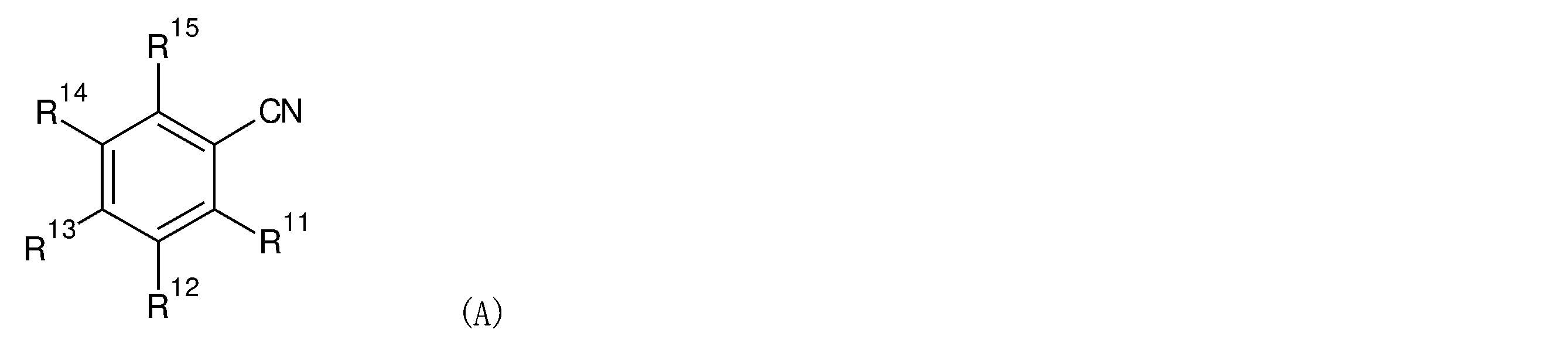
- Patent Document 1 discloses a compound represented by the formula (A).
- R 11 ⁇ R 15 represents a cyano group
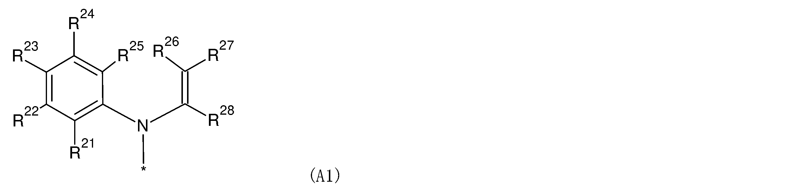
- at least one of R 11 ⁇ R 15 represents a group represented by the formula (A1)
- the remaining R 11 ⁇ R 15 Represents a hydrogen atom or substituent.
- R 21 to R 28 independently represent a hydrogen atom or a substituent. However, R 25 and R 26 may be combined to form a single bond, and R 27 and R 28 may be combined together to form a substituted or unsubstituted benzene with a carbon atom to which R 27 and R 28 are bonded. A ring may be formed.
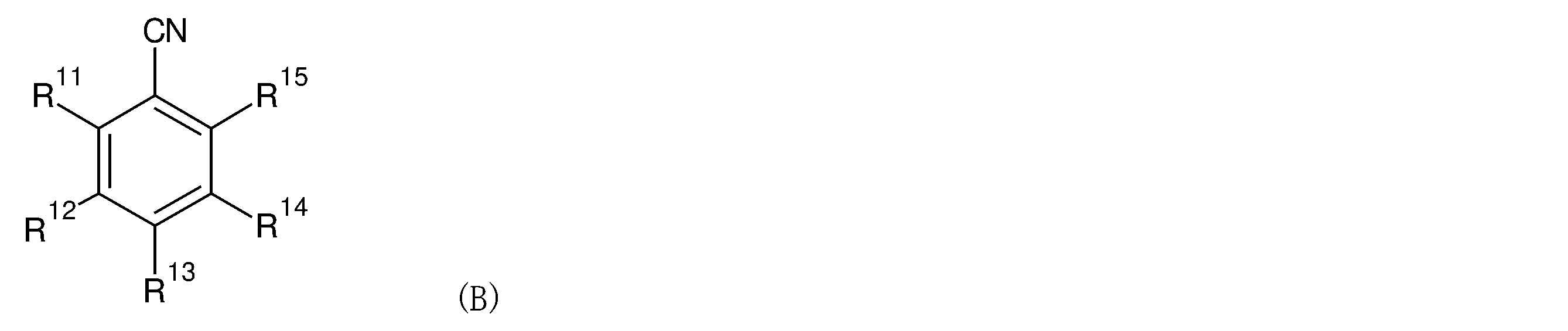
- Patent Document 2 discloses a compound represented by the formula (B).
- R 11 to R 15 each independently represent a hydrogen atom or a substituent, one of R 11 to R 15 represents a cyano group, and 1 to 3 of R 11 to R 15 are represented.
- the number is an aryl group Ar which may be substituted with an alkyl group or an aryl group (however, the benzene ring constituting the latter aryl group contains an oxygen atom or a sulfur atom as a ring skeleton constituent atom in addition to the carbon atom.
- the rings may be condensed, but the rings containing heteroatoms other than oxygen atoms and sulfur atoms as ring skeleton constituent atoms are not condensed.) Of R 11 to R 15 .
- An object of the present invention is to provide an isophthalonitrile compound having excellent light emitting characteristics, a light emitting material, and a light emitting device using the same.
- R 1 , R 2 , R 3 and R 4 are independently hydrogen atoms, alkyl groups, or heteroaryl groups, and R 1 , R 2 , R 3 and R 4 are hydrogen atoms at the same time. There is no.
- R 5 and R 6 are independently hydrogen atoms, alkyl groups, aryl groups, or heteroaryl groups, and R 5 and R 6 are not hydrogen atoms at the same time.
- L 1 and L 2 are independently aryl groups.
- R 7 , R 8 , R 9 and R 10 are independently hydrogen atoms, aryl groups, or heteroaryl groups, and R 7 , R 8 , R 9 and R 10 are hydrogen atoms at the same time. None, and L 1 and L 2 are independently aryl groups.
- the isophthalonitrile compound according to the present invention is useful as a light emitting material.
- the light emitting device containing the light emitting material according to the present invention can realize excellent luminous efficiency.
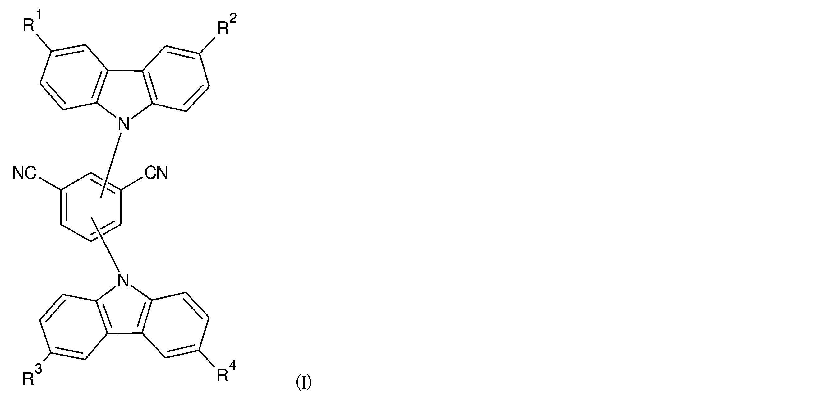
- the isophthalonitrile compound of the present invention is a compound represented by the formula (I), the formula (II) or the formula (III).
- R 1 , R 2 , R 3 and R 4 are independently hydrogen atoms, alkyl groups, or heteroaryl groups, and R 1 , R 2 , R 3 and R 4 are At the same time, it is not a hydrogen atom.
- R 5 and R 6 are independently hydrogen atoms, alkyl groups, aryl groups, or heteroaryl groups, and R 5 and R 6 are not hydrogen atoms at the same time.
- L 1 and L 2 are independently aryl groups.
- R 7 , R 8 , R 9 and R 10 are independently hydrogen atoms, aryl groups, or heteroaryl groups, and R 7 , R 8 , R 9 and R 10 are simultaneous. It cannot be a hydrogen atom.
- L 1 and L 2 are independently aryl groups.
- the term "unsubstituted” means that there are only parental groups. When only the name of the parent group is described, it means “unsubstituted” unless otherwise specified.
- the term “substituted” means that any hydrogen atom of the parent group is substituted with a group having the same or different structure as the mother nucleus. Therefore, a "substituent” is another group attached to a parent group.
- the number of substituents may be one or two or more. The two or more substituents may be the same or different.
- the "substituent” is chemically acceptable and is not particularly limited as long as it has the effect of the present invention.
- groups that can be “substituents” include the following groups. Halogeno groups such as fluoro group, chloro group, bromo group, iod group; C1-6 such as methyl group, ethyl group, n-propyl group, i-propyl group, n-butyl group, s-butyl group, i-butyl group, t-butyl group, n-pentyl group, n-hexyl group, etc.
- Alkyl group Vinyl group, 1-propenyl group, 2-propenyl group, 1-butenyl group, 2-butenyl group, 3-butenyl group, 1-methyl-2-propenyl group, 2-methyl-2-propenyl group, 1-pentenyl group , 2-Pentenyl group, 3-Pentenyl group, 4-Pentenyl group, 1-methyl-2-butenyl group, 2-Methyl-2-butenyl group, 1-hexenyl group, 2-hexenyl group, 3-hexenyl group, 4 -C2-6 alkenyl groups such as hexenyl group, 5-hexenyl group;
- Ethynyl group 1-propynyl group, 2-propynyl group, 1-butynyl group, 2-butynyl group, 3-butynyl group, 1-methyl-2-propynyl group, 2-methyl-3-butynyl group, 1-pentynyl group , 2-Pentynyl group, 3-Pentynyl group, 4-Pentynyl group, 1-methyl-2-butynyl group, 2-Methyl-3-pentynyl group, 1-hexynyl group, 1,1-dimethyl-2-butynyl group, etc.
- C2-6 alkynyl groups C3-8 cycloalkyl groups such as cyclopropyl group, cyclobutyl group, cyclopentyl group, cyclohexyl group, cycloheptyl group, cubicyl group; C3-8 cycloalkenyl groups such as 2-cyclopropenyl group, 2-cyclopentenyl group, 3-cyclohexenyl group, 4-cyclooctenyl group; C6-10 aryl groups such as phenyl group and naphthyl group; 5-membered heteroaryl groups such as pyrrolyl group, frill group, thienyl group, imidazolyl group, pyrazolyl group, oxazolyl group, isooxazolyl group, thiazolyl group, isothiazolyl group, triazolyl group, oxadiazolyl group, thiadiazolyl group, tetrazolyl group; A 6-membered heteroaryl
- Hydroxy group oxo group; C1-6 alkoxy groups such as methoxy group, ethoxy group, n-propoxy group, i-propoxy group, n-butoxy group, s-butoxy group, i-butoxy group, t-butoxy group; C2-6 alkenyloxy groups such as vinyloxy group, allyloxy group, propenyloxy group, butenyloxy group; C2-6 alkynyloxy groups such as ethynyloxy group and propargyloxy group; C6-10 aryloxy groups such as phenoxy group and naphthoxy group; 5- to 6-membered heteroaryloxy groups such as thiazolyloxy groups and pyridyloxy groups;
- Carboxylic group Formyl group; C1-6 alkylcarbonyl group such as acetyl group, propionyl group; Formyloxy group; C1-6 alkylcarbonyloxy group such as acetyloxy group, propionyloxy group; C1-6 alkoxycarbonyl groups such as methoxycarbonyl group, ethoxycarbonyl group, n-propoxycarbonyl group, i-propoxycarbonyl group, n-butoxycarbonyl group, t-butoxycarbonyl group;
- C1-6 haloalkyl groups such as chloromethyl group, chloroethyl group, trifluoromethyl group, 1,2-dichloro-n-propyl group, 1-fluoro-n-butyl group, perfluoro-n-pentyl group; C2-6 haloalkenyl groups such as 2-chloro-1-propenyl group, 2-fluoro-1-butenyl group; C2-6 haloalkynyl groups such as 4,4-dichloro-1-butynyl group, 4-fluoro-1-pentynyl group, 5-bromo-2-pentynyl group; C3-6 halocycloalkyl groups such as 3,3-difluorocyclobutyl group; C1-6 haloalkoxy groups such as 2-chloro-n-propoxy group, 2,3-dichlorobutoxy group, trifluoromethoxy group, 2,2,2-trifluoroethoxy group; C2-6 haloalken
- Cyano group Nitro group; Amino group; C1-6 alkylamino groups such as methylamino group, dimethylamino group, diethylamino group; C6-10 arylamino groups such as anilino group and naphthylamino group; Formylamino group; C1-6 alkylcarbonylamino group such as acetylamino group, propanoylamino group, butyrylamino group, i-propylcarbonylamino group; C1-6 alkoxycarbonylamino groups such as methoxycarbonylamino group, ethoxycarbonylamino group, n-propoxycarbonylamino group, i-propoxycarbonylamino group; C1-6 alkyl sulfoxide imino groups such as S, S-dimethyl sulfoxide imino groups;
- Aminocarbonyl group C1-6 alkylaminocarbonyl groups such as methylaminocarbonyl group, dimethylaminocarbonyl group, ethylaminocarbonyl group, i-propylaminocarbonyl group; Imino C1-6 alkyl groups such as iminomethyl group, (1-imino) ethyl group, (1-imino) -n-propyl group; Hydroxyimino C1-6 alkyl groups such as hydroxyiminomethyl group, (1-hydroxyimino) ethyl group, (1-hydroxyimino) propyl group; C1-6 alkoxyimino C1-6 alkyl groups such as methoxyiminomethyl group, (1-methoxyimino) ethyl group;
- C1-6 alkylthio groups such as methylthio group, ethylthio group, n-propylthio group, i-propylthio group, n-butylthio group, i-butylthio group, s-butylthio group, t-butylthio group; C1-6 haloalkylthio groups such as trifluoromethylthio group, 2,2,2-trifluoroethylthio group; C2-6 alkenylthio groups such as vinylthio groups and allylthio groups; C2-6 alkynylthio groups such as ethynylthio group and propargylthio group; C1-6 alkylsulfinyl groups such as methylsulfinyl group, ethylsulfinyl group, t-butylsulfinyl group; C1-6 haloalkylsulfinyl groups such as trifluoro
- Tri-C1-6 alkylsilyl groups such as trimethylsilyl group, triethylsilyl group, t-butyldimethylsilyl group; Tri-C6-10 arylsilyl groups such as triphenylsilyl groups. Further, in these "substituents", any hydrogen atom in the substituent may be substituted with a group having a different structure.
- C1 to 6 indicate that the number of carbon atoms of the parent group is 1 to 6 or the like. This number of carbon atoms does not include the number of carbon atoms present in the substituent.
- an ethoxybutyl group is classified as a C2 alkoxy C4 alkyl group because the parent group is a butyl group and the substituent is an ethoxy group.
- alkyl groups in R 1 , R 2 , R 3 , R 4 , R 5 and R 6 include methyl group, ethyl group, n-propyl group, i-propyl group, n-butyl group and s-butyl group. , I-butyl group, t-butyl group, n-pentyl group, n-hexyl group and the like, and an alkyl group having 1 to 6 carbon atoms is preferable.
- the number of carbon atoms constituting the "aryl group" in R 5 , R 6 , R 7 , R 8 , R 9 and R 10 and L 1 and L 2 is preferably 6 to 40, more preferably 6 to 20. 6 to 14 are even more preferable, and 6 carbon atoms are even more preferable.
- the unsubstituted aryl group include a phenyl group, a 1-naphthyl group, a 2-naphthyl group, an azulenyl group, an indanyl group, a tetralinyl group and the like.
- substituted aryl group 4-fluorophenyl group, 4-chlorophenyl group, 2,4-dichlorophenyl group, 3,4-dichlorophenyl group, 3,5-dichlorophenyl group, 2,6-difluorophenyl group, 4-trifluoro Examples thereof include methylphenyl group, 4-methoxyphenyl group, 3,4-dimethoxyphenyl group, 3,4-methylenedioxyphenyl group, 4-trifluoromethoxyphenyl group, 4-methoxy-1-naphthyl group and the like. ..
- the "aryl group” is preferably a phenyl group.
- the "heteroaryl group" in R 1 , R 2 , R 3 , R 4 , R 5 , R 6 , R 7 , R 8 , R 9 and R 10 may be monocyclic or polycyclic.
- the polycyclic heteroaryl group may be any of a saturated ring, an unsaturated ring, and an aromatic ring as long as at least one ring is a heteroaromatic ring.
- the number of atoms constituting the heteroaryl group is preferably 5 to 40, more preferably 5 to 26, and even more preferably 5 to 14.
- the heteroaryl group includes a 5-membered ring such as a pyrrolyl group, a furyl group, a thienyl group, an imidazolyl group, a pyrazolyl group, an oxazolyl group, an isooxazolyl group, a thiazolyl group, an isothiazolyl group, a triazolyl group, an oxadiazolyl group, a thiadiazolyl group and a tetrazolyl group.
- a 5-membered ring such as a pyrrolyl group, a furyl group, a thienyl group, an imidazolyl group, a pyrazolyl group, an oxazolyl group, an isooxazolyl group, a thiazolyl group, an isothiazolyl group, a triazolyl group, an oxadiazolyl group, a thiadiazolyl group and a
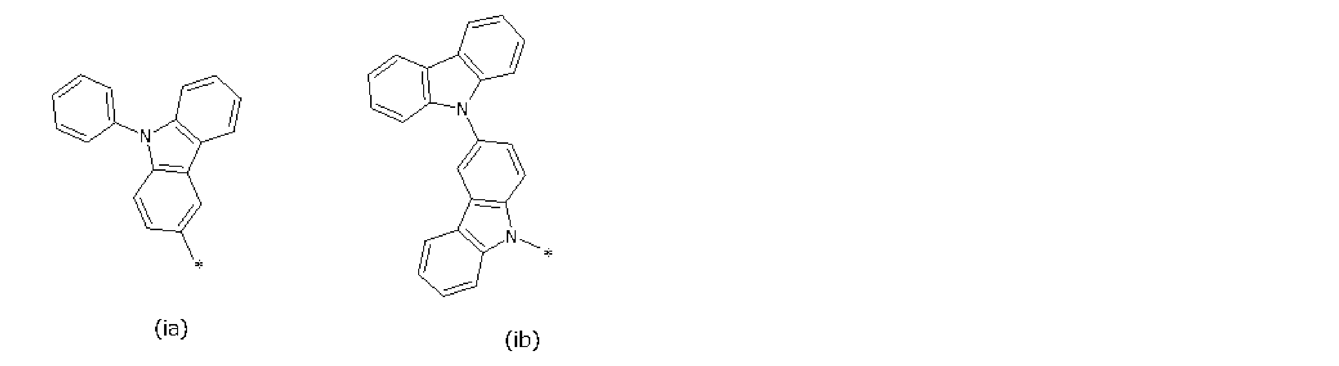
- Heteroaryl group 6-membered heteroaryl group such as pyridyl group, pyrazinyl group, pyrimidinyl group, pyridadinyl group, triazinyl group; indolyl group, benzofuryl group, benzothienyl group, benzoimidazolyl group, benzoxazolyl group, benzothiazolyl group, Heteroaryl groups of fused rings such as a quinolyl group, an isoquinolyl group, and a quinoxalinyl group; can be mentioned, but the group represented by the following formula (ia) or (ib) is preferable.
- R 1 , R 2 , R 3 and R 4 are preferably C1 to 6 alkyl groups independently.
- R 5 and R 6 are independently represented by a hydrogen atom, a C1 to 6 alkyl group, a phenyl group, a group represented by the above formula (ia), or the above formula (ib). It is preferably a group.
- R 5 and R 6 are not hydrogen atoms at the same time.
- L 1 and L 2 are preferably phenyl groups.
- R 7 , R 8 , R 9 and R 10 are independently hydrogen atoms, C1 to 6 alkyl groups, phenyl groups, groups represented by the above formula (ia), or the above formula. It is preferably the group represented by (ib).
- R 7 , R 8 , R 9 and R 10 are not hydrogen atoms at the same time.
- at least one of R 7 , R 8 , R 9 and R 10 is a C1 to 6 alkyl group or a phenyl group, it is preferable that the other group is not a hydrogen atom.
- L 1 and L 2 are preferably phenyl groups.
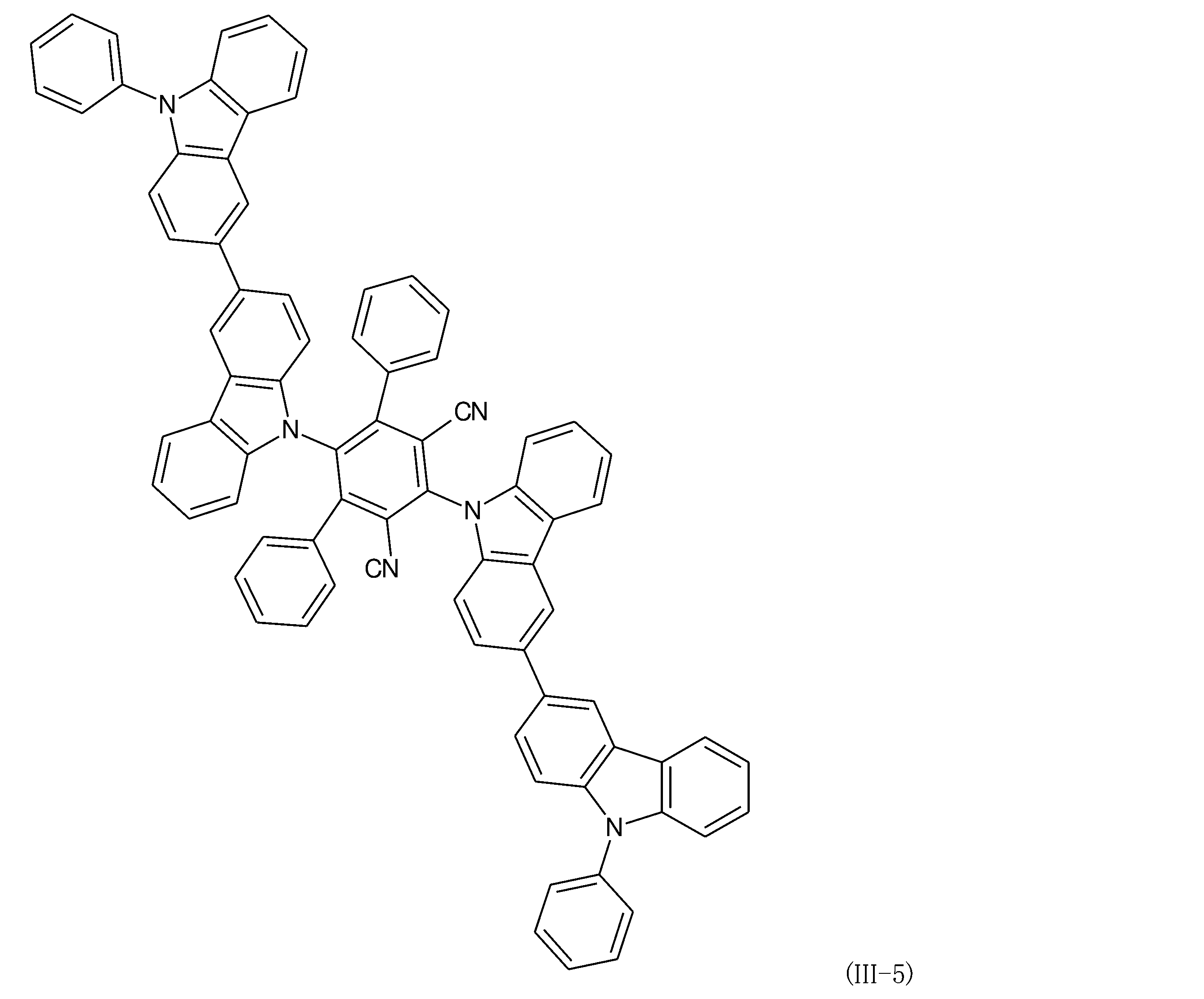
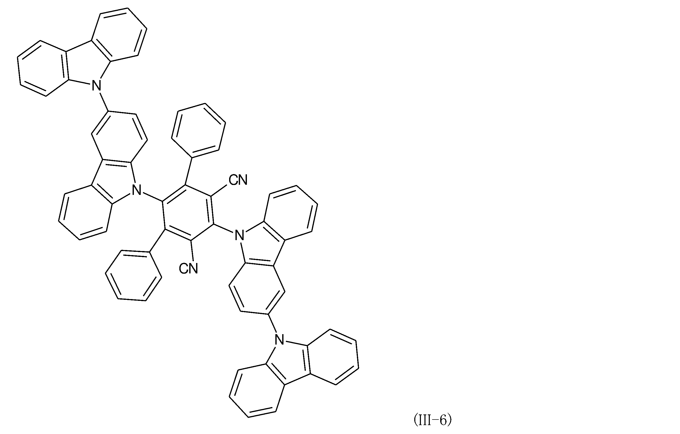
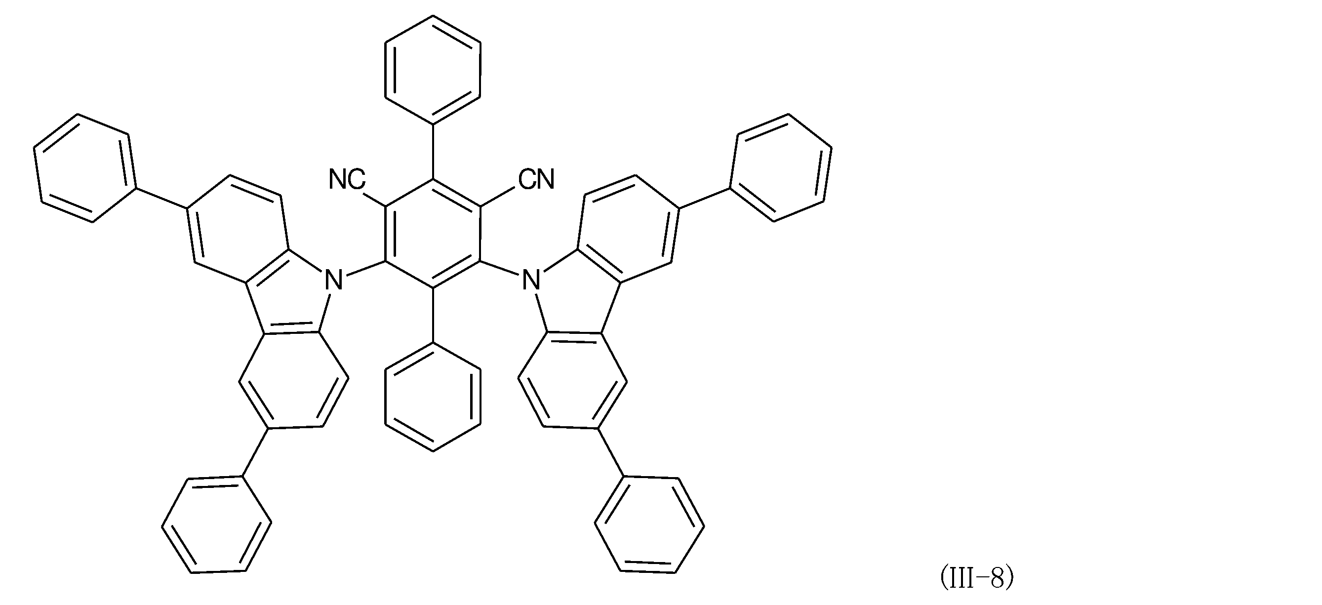
- isophthalonitrile compound of the present invention include the following compounds (I-1) to (III-8), preferably compounds (I-1), (I-2) and (II-). 1), (II-2), (II-3) or (II-6) can be mentioned.
- the isophthalonitrile compound of the present invention can be obtained by performing a combination of known synthetic reactions (for example, coupling reaction, substitution reaction, etc.).
- the synthesized compound can be purified by column chromatography, adsorption purification with silica gel, activated carbon, activated white clay, etc., recrystallization with a solvent, crystallization method, or the like.
- the compound can be identified by NMR analysis or the like.
- the compound of the present invention can be obtained, for example, as follows.
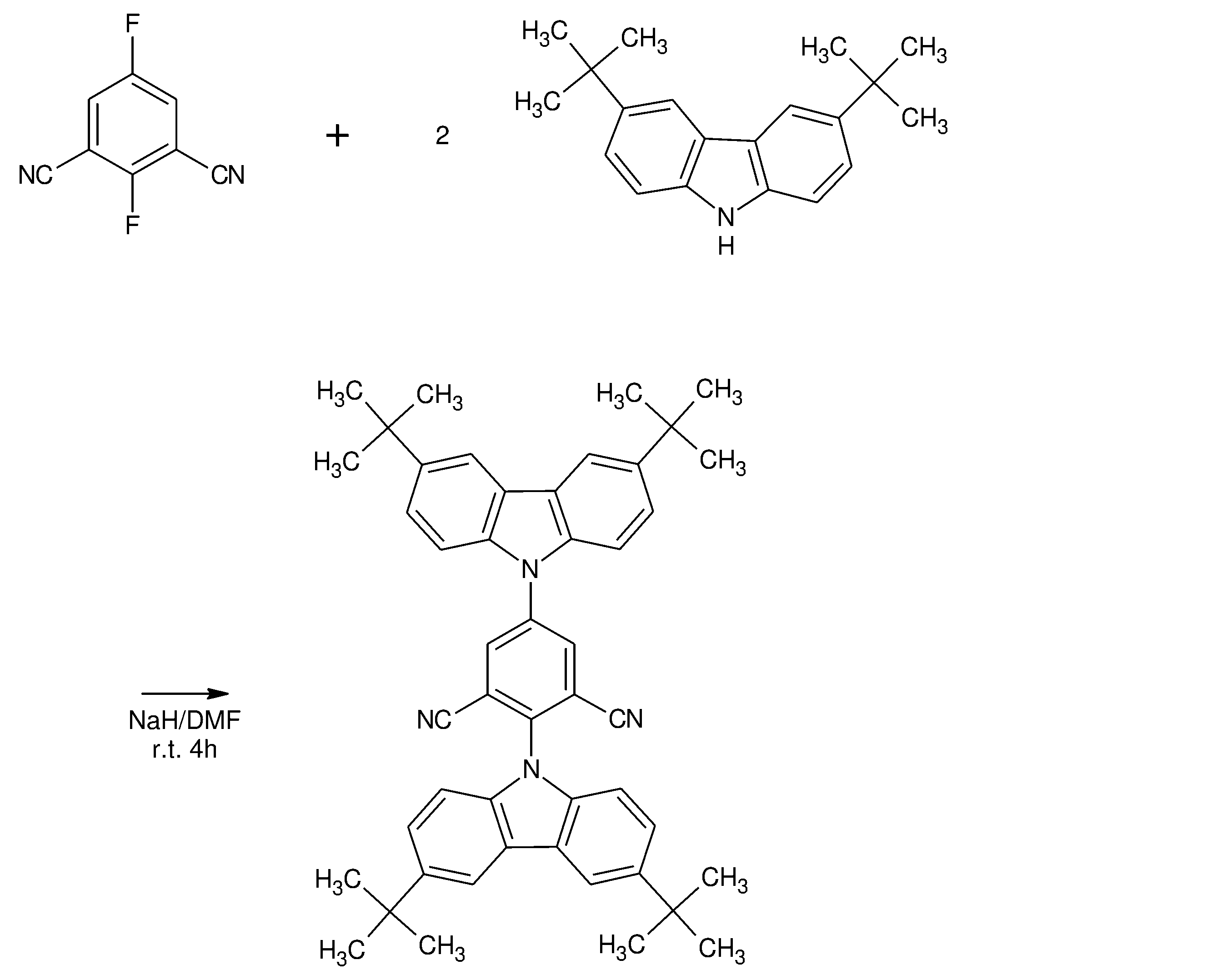
- Example 1 Synthesis of 2,5-bis (3,6-di-tert-butyl-9H-carbazole-9-yl) isophthalonitrile (Compound (I-1): BCz-2IN-I)
- the reaction solution is cooled with ice water, water and ethyl acetate are added, the organic layer is separated, the aqueous layer is further extracted with ethyl acetate, and the mixed organic layer is washed with saturated brine.
- the target compound is obtained by dehydrating the organic layer with magnesium sulfate, filtering and concentrating the organic layer, and then purifying the organic layer.
- the isophthalonitrile compound of the present invention can be used as a light emitting material.
- the light emitting material of the present invention can provide a light emitting element such as an organic photoluminescence element and an organic electroluminescence element. Since the isophthalonitrile compound of the present invention has a function of assisting the light emission of another light emitting material (host material), it can be used by doping with another light emitting material.
- the organic photoluminescence element of the present invention is formed by providing a light emitting layer containing the light emitting material of the present invention on a substrate.
- the light emitting layer can be obtained by a coating method such as spin coating, a printing method such as an inkjet printing method, a vapor deposition method or the like.
- the organic electroluminescence element of the present invention is formed by providing an organic layer between an anode and a cathode.
- the "organic layer" in the present invention means a layer made of substantially organic substances located between the anode and the cathode, and these layers contain inorganic substances as long as the performance of the light emitting device of the present invention is not impaired. You may.
- an anode, a hole injection layer, a hole transport layer, an electron blocking layer, a light emitting layer, a hole blocking layer, and an electron transport layer are sequentially formed on a substrate.
- Examples thereof include those composed of a cathode and those having an electron injection layer between the electron transport layer and the cathode.
- an anode, a hole transport layer, a light emitting layer, an electron transport layer, an electron injection layer, and a cathode can be sequentially used on the substrate.
- the light emitting material of the present invention may be doped not only in the light emitting layer but also in the hole injection layer, the hole transport layer, the electron blocking layer, the hole blocking layer, the electron transport layer, or the electron injection layer.
- the substrate serves as a support for the light emitting element, and silicon plates, quartz plates, glass plates, metal plates, metal foils, resin films, resin sheets, etc. are used.
- a glass plate or a transparent synthetic resin plate such as polyester, polymethacrylate, polycarbonate, or polysulfone is preferable.
- a synthetic resin substrate it is necessary to pay attention to the gas barrier property. If the gas barrier property of the substrate is too low, the light emitting element may be deteriorated by the outside air passing through the substrate. Therefore, it is preferable to provide a dense silicon oxide film or the like on either one side or both sides of the synthetic resin substrate to ensure gas barrier properties.
- An anode is provided on the substrate.
- a material having a large work function is generally used for the anode.
- the material for the anode include metals such as aluminum, gold, silver, nickel, palladium, and platinum; metal oxides such as indium oxide, tin oxide, ITO, zinc oxide, In 2 O 3- ZnO, and IGZO, and iodine.
- metal halides such as copper oxide, carbon black, and conductive polymers such as poly (3-methylthiophene), polypyrrole, and polyaniline.
- the anode is usually formed by a sputtering method, a vacuum vapor deposition method, or the like.
- metal fine particles such as silver, fine particles such as copper iodide, carbon black, conductive metal oxide fine particles, conductive polymer fine powder, etc.
- they are dispersed in an appropriate binder resin solution and placed on the substrate.
- An anode can also be formed by coating.
- a thin film can be formed directly on the substrate by electrolytic polymerization, or an anode can be formed by applying the conductive polymer on the substrate.
- the anode can also be formed by laminating two or more different substances.
- the thickness of the anode depends on the transparency required. When transparency is required, it is desirable that the transmittance of visible light is usually 60% or more, preferably 80% or more, in which case the thickness is usually 10 to 1000 nm, preferably 10 to 10 to. It is 200 nm. If opaque, the anode may be as thick as the substrate.
- the sheet resistance of the anode is preferably several hundred ⁇ / ⁇ or more.
- triphenylamine trimeric and tetramer such as an arylamine compound having a structure linked by a divalent group containing no hetero atom, an accepting heterocyclic compound such as hexacyanoazatriphenylene, and a coating type polymer material.
- these materials can be thin-filmed by a known method such as a spin coating method or an inkjet method.
- the hole transport material used for the hole transport layer provided as needed, it is preferable that the hole injection efficiency from the anode is high and the injected holes can be efficiently transported.
- the ionization potential is small, the transparency to visible light is high, the hole mobility is high, the stability is excellent, and impurities that become traps are unlikely to be generated during manufacturing or use.
- the element has higher heat resistance. Therefore, a material having a Tg value of 70 ° C. or higher is desirable.
- a triazole derivative As the hole transport layer provided as needed, a triazole derivative, an oxadiazole derivative, an imidazole derivative, a carbazole derivative, an indolocarbazole derivative, a polyarylalkane derivative, a pyrazoline derivative, a pyrazolone derivative, a phenylenediamine derivative, an arylamine derivative, Examples thereof include amino-substituted chalcone derivatives, oxazole derivatives, styrylanthracene derivatives, fluorenone derivatives, hydrazone derivatives, stilben derivatives, silazane derivatives, aniline copolymers, and conductive polymer oligomers.
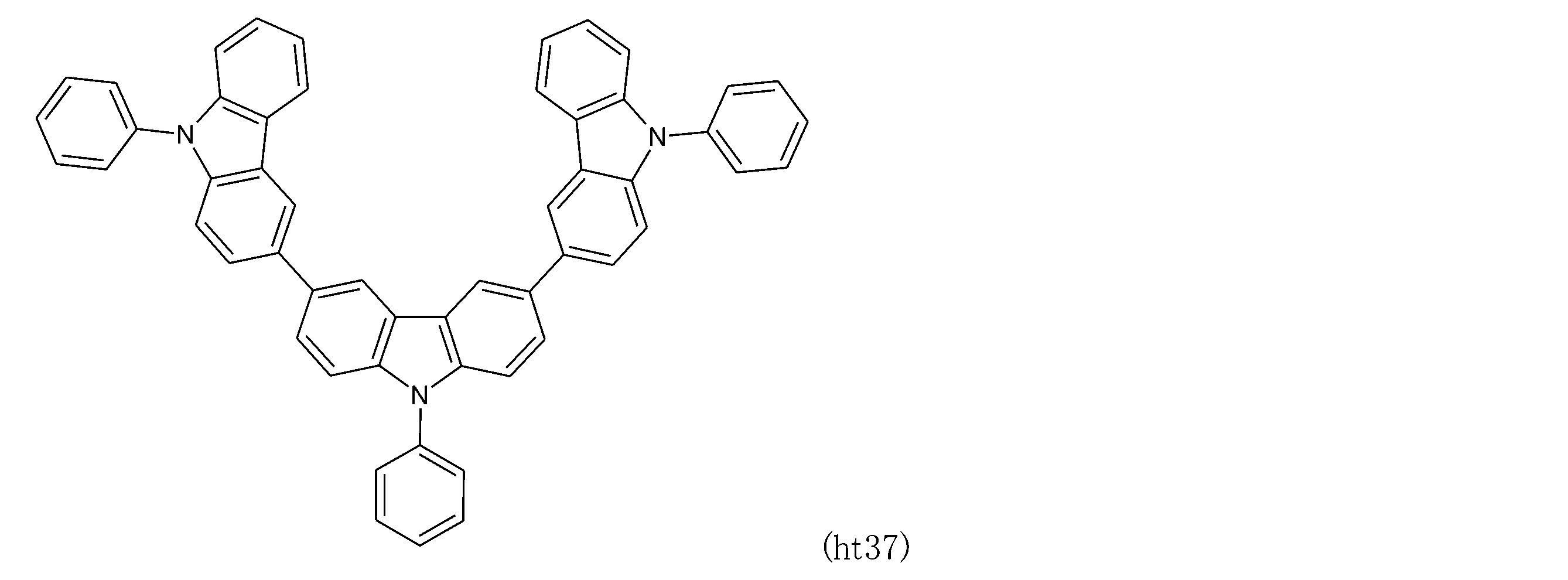
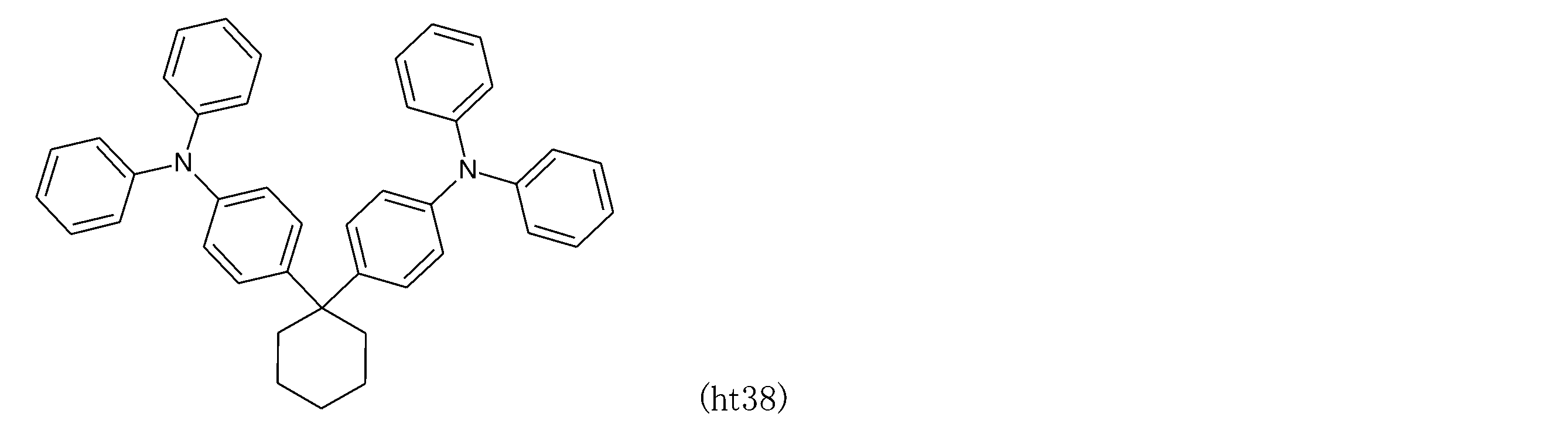
- Benzidine derivatives such as -diphenyl-N, N'-di ( ⁇ -naphthyl) -benzidine (hereinafter abbreviated as NPD), N, N, N', N'-tetrabiphenylyl benzidine, 1,1-bis [ (Di-4-trilamino) phenyl] cyclohexane (hereinafter abbreviated as TAPC), various triphenylamine trimerics and tetramers, carbazole derivatives and the like can be mentioned. These can be used alone or in combination of two or more.
- the hole transport layer may be a single-layer structure film or a laminated structure film.
- a coating type such as poly (3,4-ethylenedioxythiophene) (hereinafter abbreviated as PEDOT) / poly (styrene sulfonate) (hereinafter abbreviated as PSS) is used.
- PEDOT poly (3,4-ethylenedioxythiophene)
- PSS poly (styrene sulfonate)
- Polymer materials can be used. In addition to the vapor deposition method, these materials can be thin-filmed by a known method such as a spin coating method or an inkjet method.
- a material usually used for the layer is further P-doped with trisbromophenylamine hexachloroantimony, or a polymer having a PD structure in its partial structure. Compounds and the like can be used.
- a hole injecting / transporting host material a carbazole derivative such as CBP, TCTA, or mCP can be used.
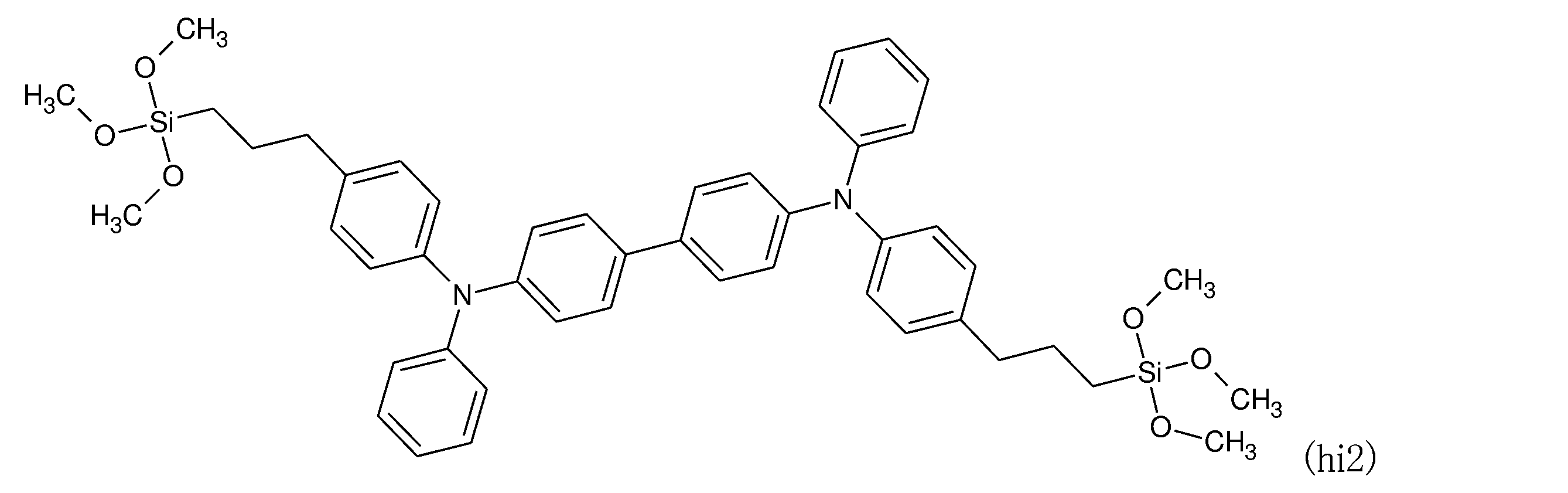
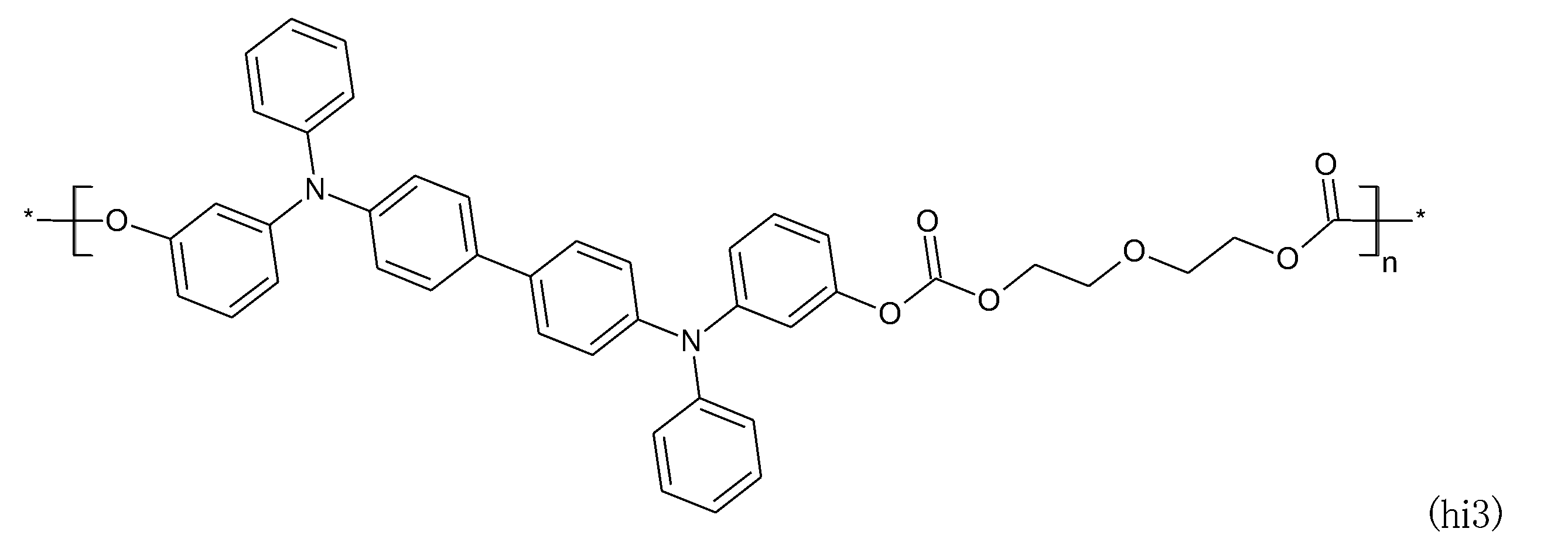
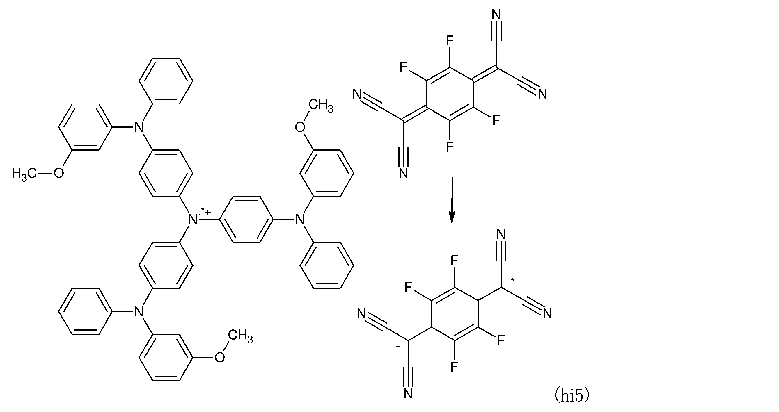
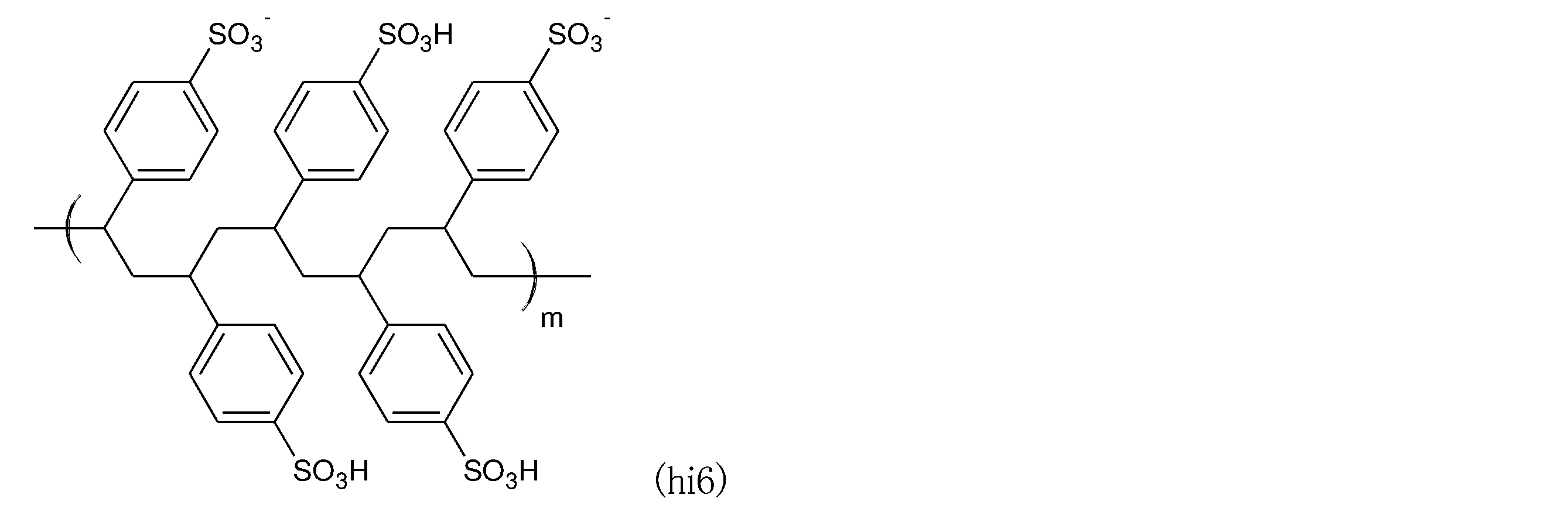
- the preferred compounds (hi1) to (hi7) that can be used as the hole injection material are listed below.
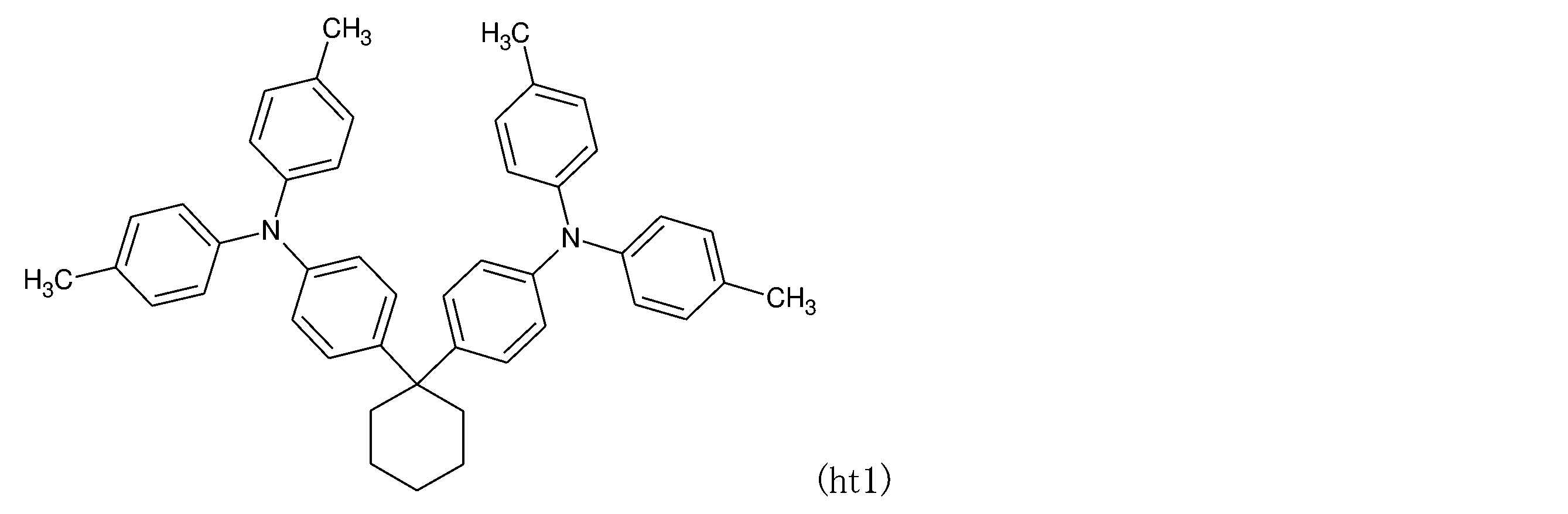
- the preferred compounds (ht1) to (ht38) that can be used as the hole transport material are listed below.
- TCTA 4,4', 4 "-tri (N-carbazolyl) triphenylamine
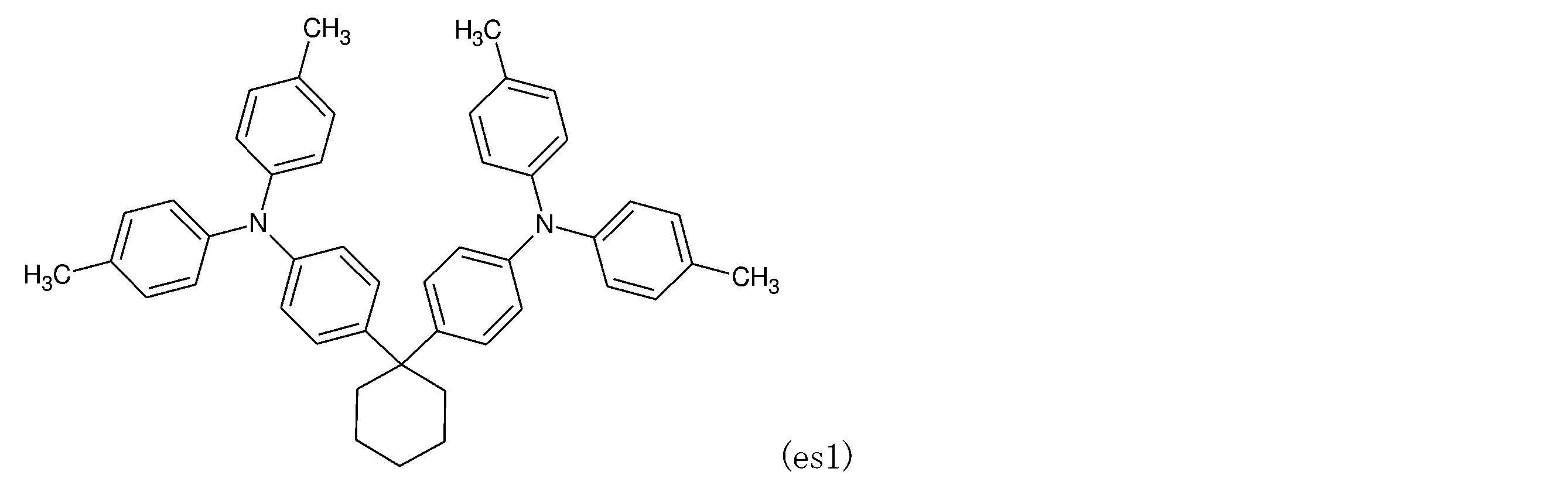
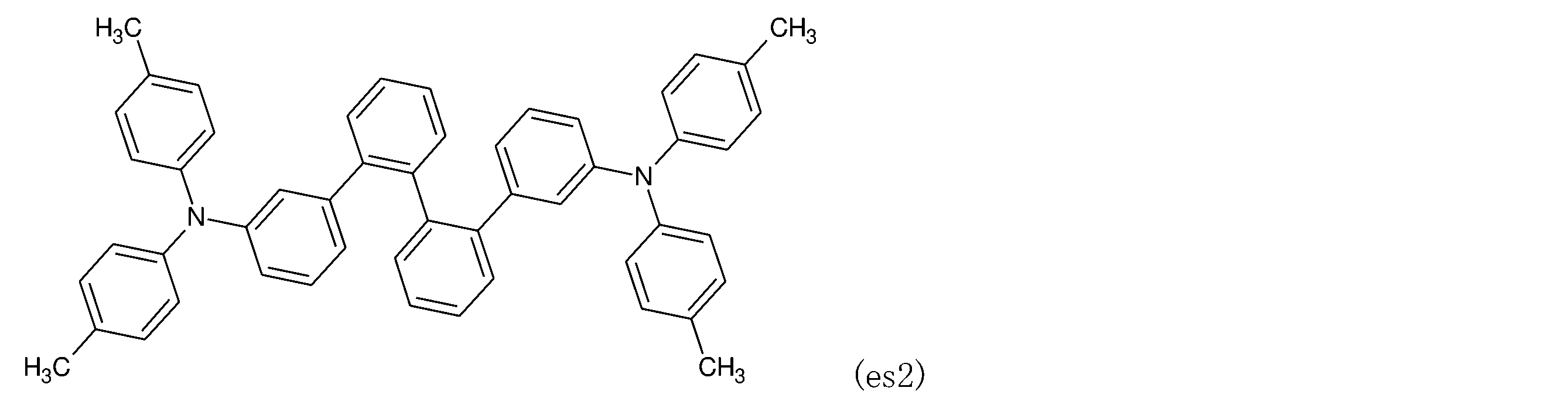
- TCTA 9,9-bis [4- (carbazole-9-)" as an electron blocking layer provided as needed.
- Ill phenyl] fluorene, 1,3-bis (carbazole-9-yl) benzene (hereinafter abbreviated as mCP), 2,2-bis (4-carbazole-9-ylphenyl) adamantan (hereinafter Ad-Cz) Carbazole derivatives such as (abbreviated as), triphenylsilyl groups typified by 9- [4- (carbazole-9-yl) phenyl] -9- [4- (triphenylsilyl) phenyl] -9H-fluorene and tria.
- the electron blocking layer is a film having a single layer structure. It may be a film having a laminated structure, or these materials may be formed into a thin film by a known method such as a spin coating method or an inkjet method in addition to a vapor deposition method.
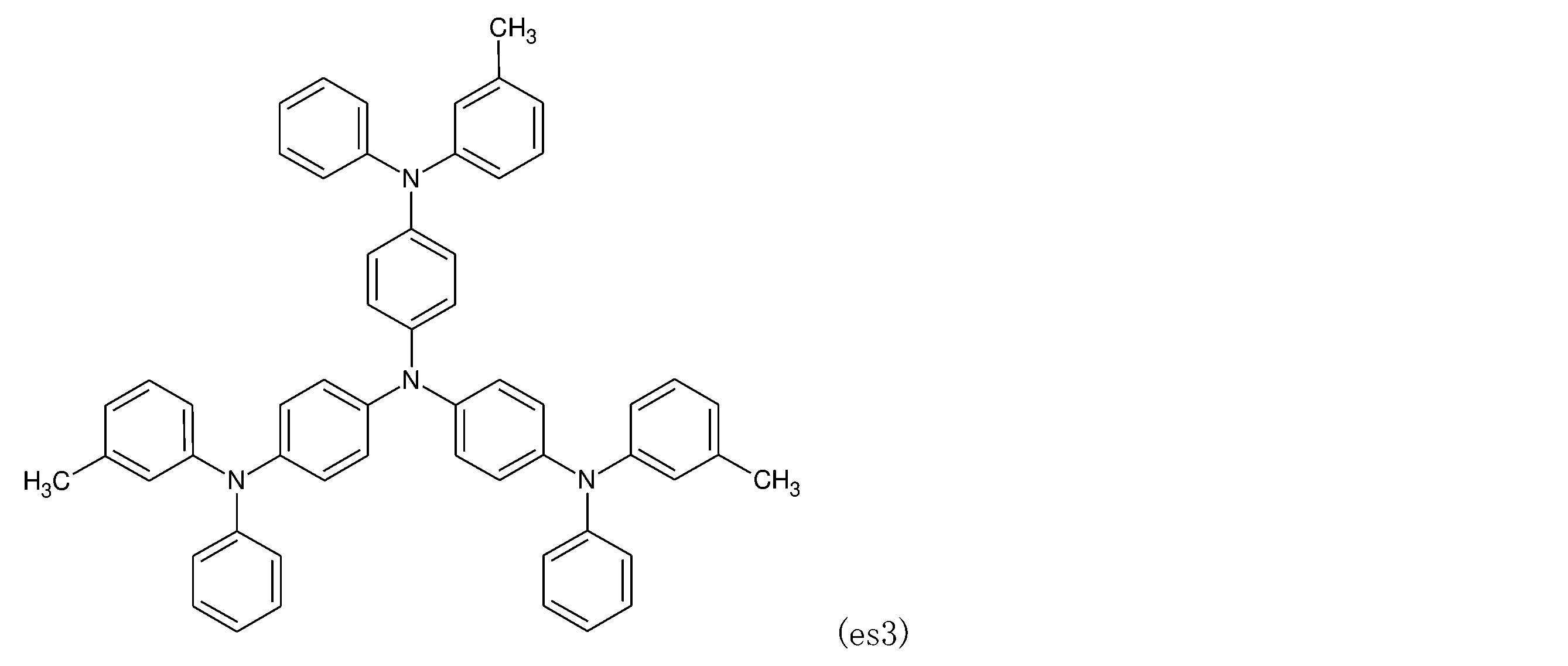
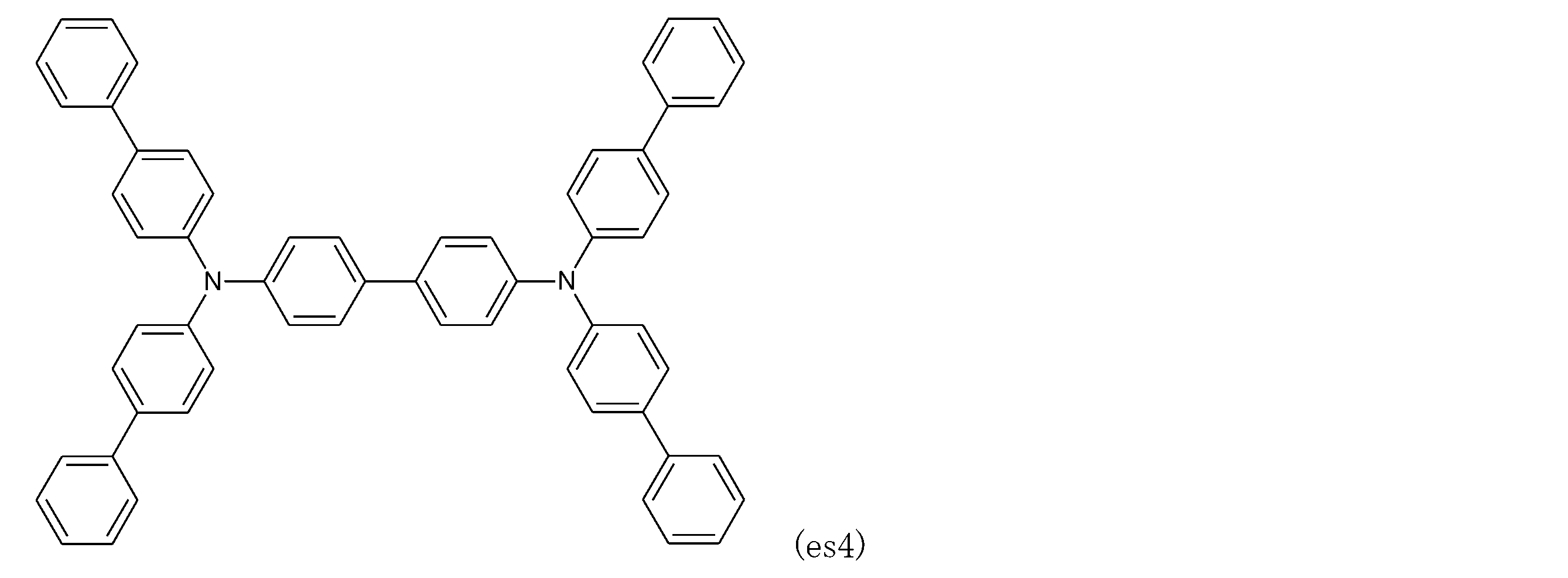
- the preferred compounds (es1) to (es5) that can be used as an electron blocking material are listed below.
- the light emitting layer is a layer having a function of emitting light by generating excitons by recombination of holes and electrons injected from each of the anode and the cathode.
- the light emitting layer may be formed by the light emitting material of the present invention alone, or may be formed by doping the host material with the light emitting material of the present invention.
- host materials include metal complexes of quinolinol derivatives such as tris (8-hydroxyquinolin) aluminum (hereinafter abbreviated as Alq3), anthracene derivatives, bisstyrylbenzene derivatives, pyrene derivatives, oxazole derivatives, and polyparaphenylene vinylene derivatives.
- the light emitting layer may contain a known dopant.
- the dopant include quinacridone, coumarin, rubrene, anthracene, perylene and derivatives thereof, benzopyran derivatives, rhodamine derivatives, aminostyryl derivatives and the like.
- a phosphorescent illuminant such as a green phosphorescent illuminant such as Ir (ppy) 3, a blue phosphorescent illuminant such as FIrpic or FIr6, or a red phosphorescent illuminant such as Btp2Ir (acac) may be used. These can be used alone or in combination of two or more.
- the light emitting layer may be a single-layer structure film or a laminated structure film. In addition to the vapor deposition method, these materials can be thin-filmed by a known method such as a spin coating method or an inkjet method.
- the lower limit of the amount of the light emitting material of the present invention that can be contained in the light emitting layer is preferably 0.1% by mass, more preferably 1% by mass, and the upper limit is preferably 50. It is by mass, more preferably 20% by mass, and even more preferably 10% by mass.
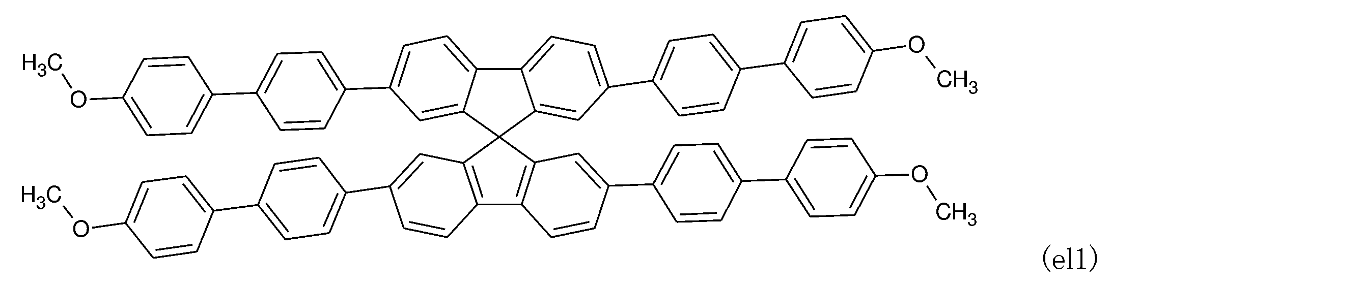
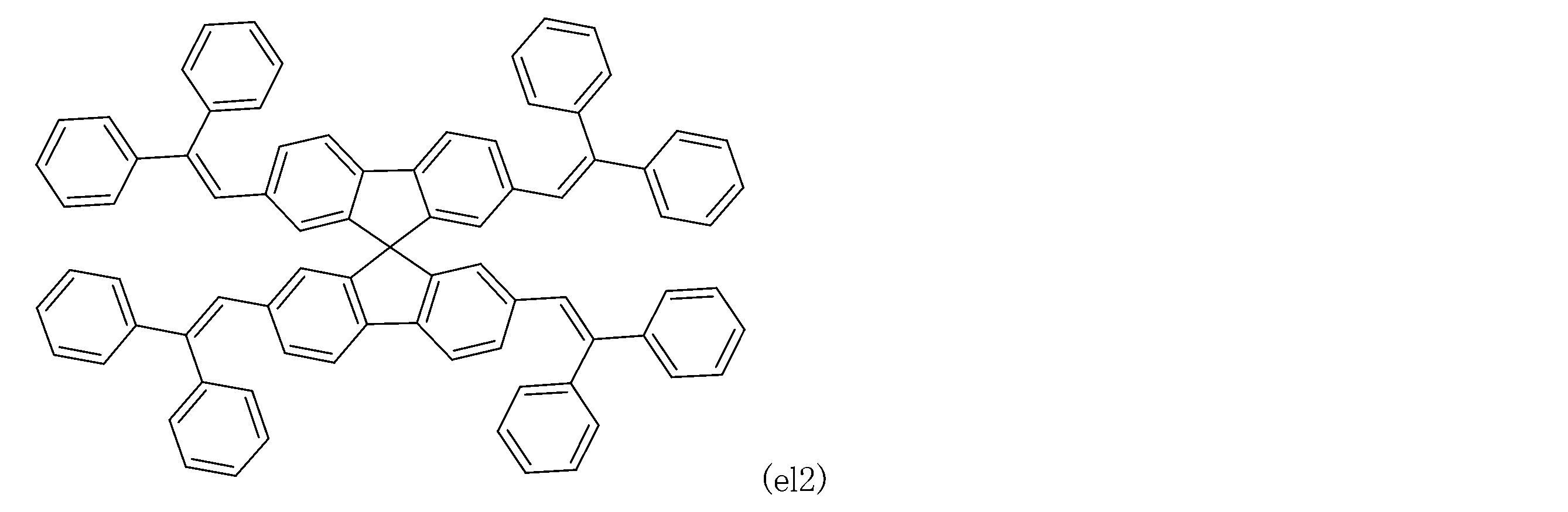
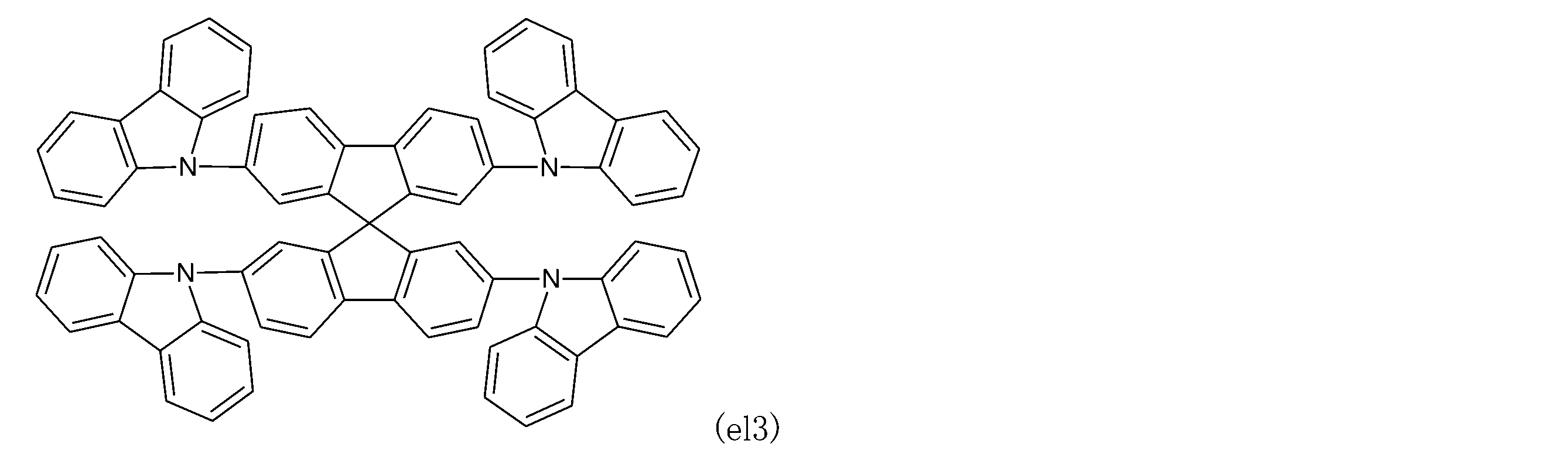
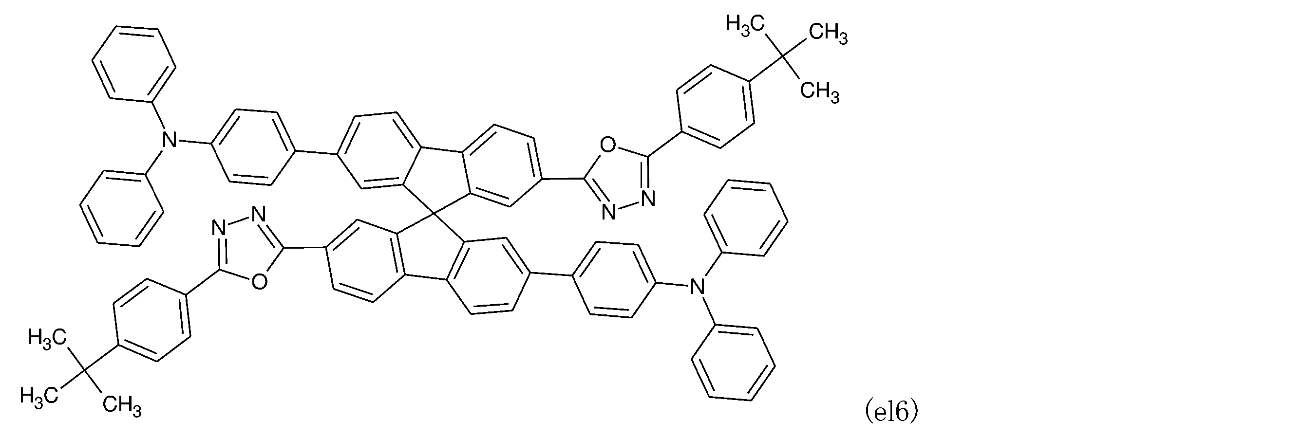
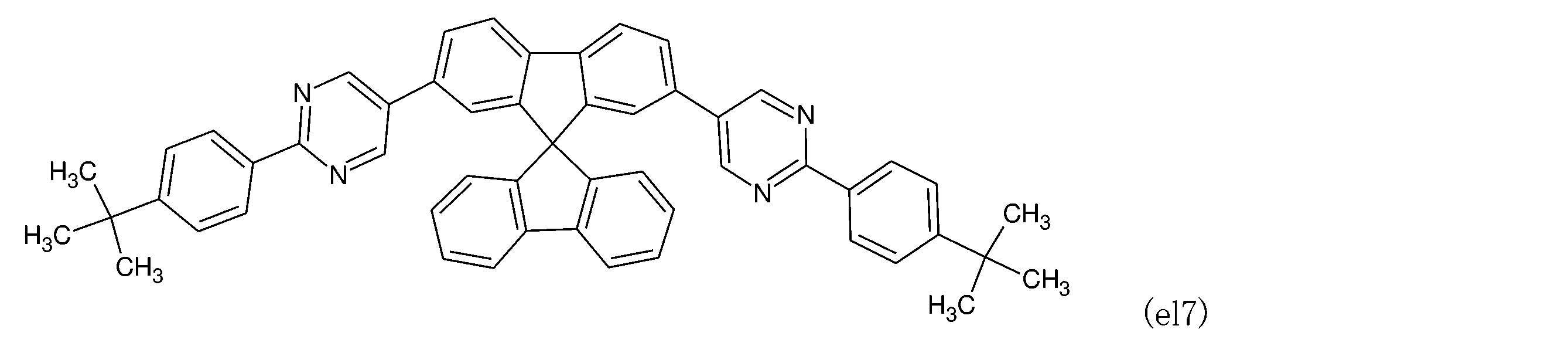
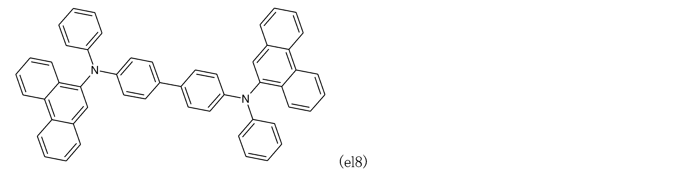
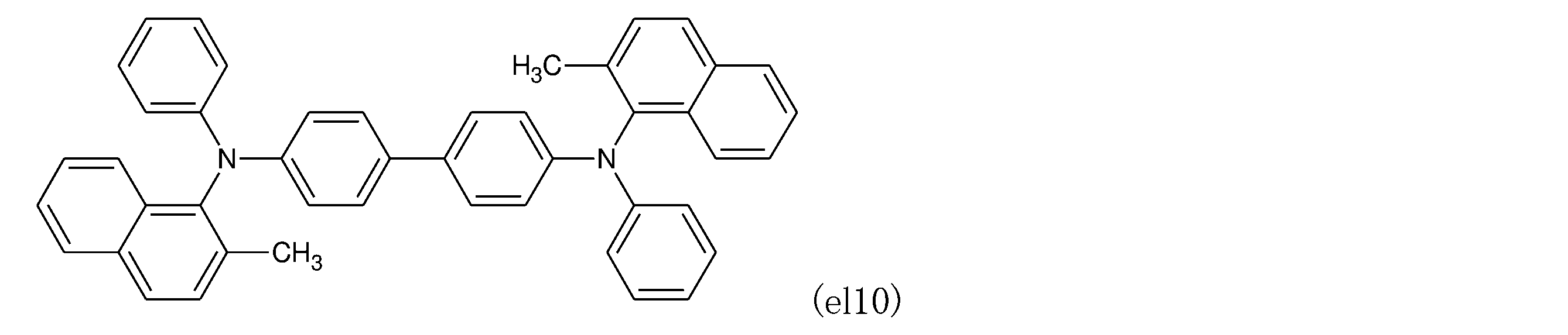
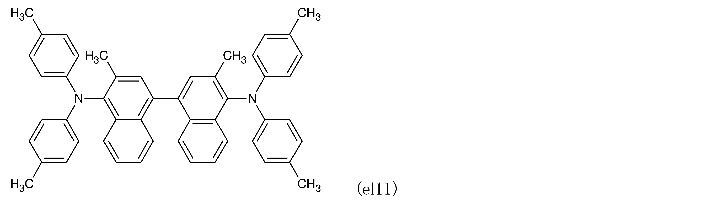
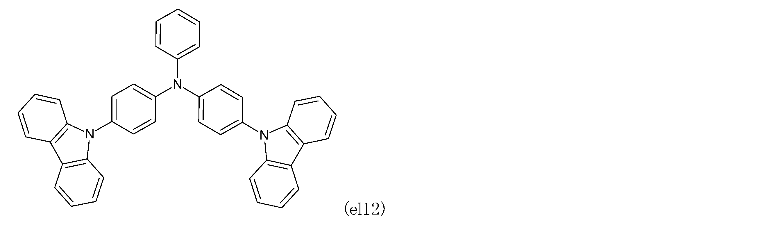
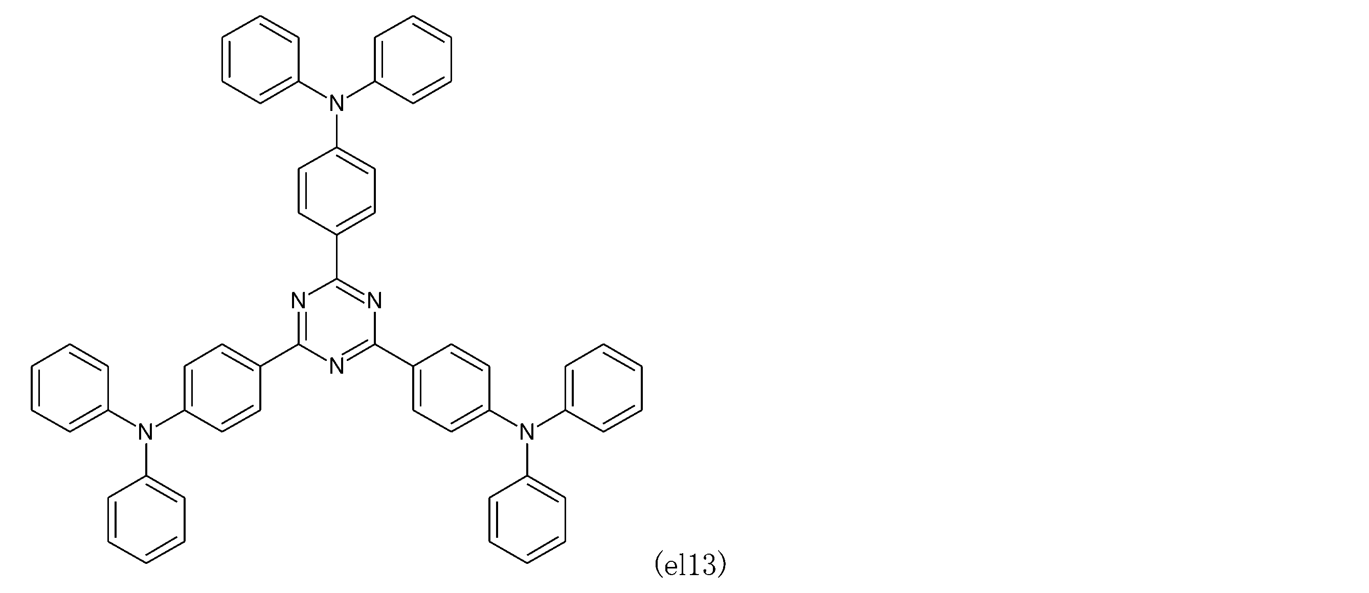
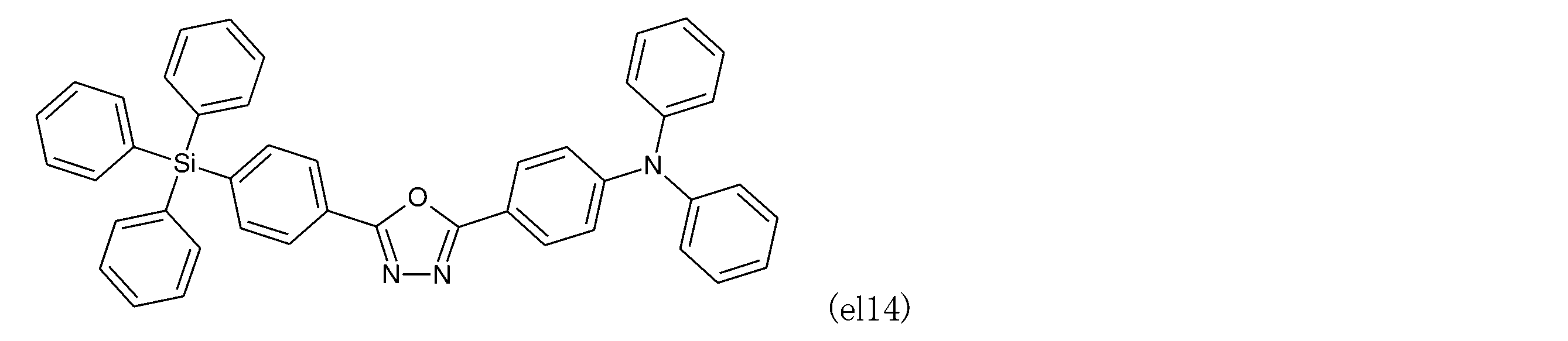
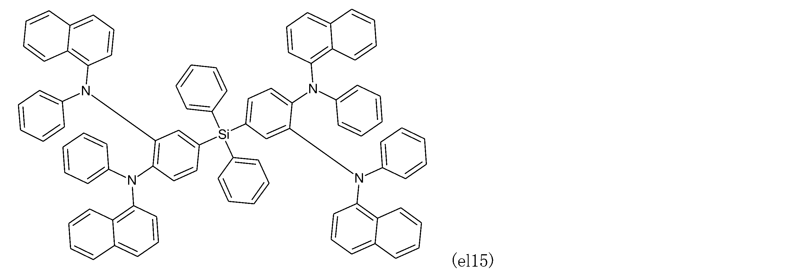
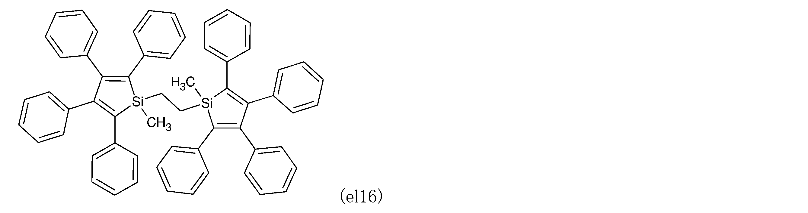
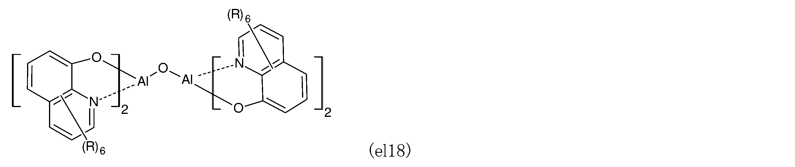
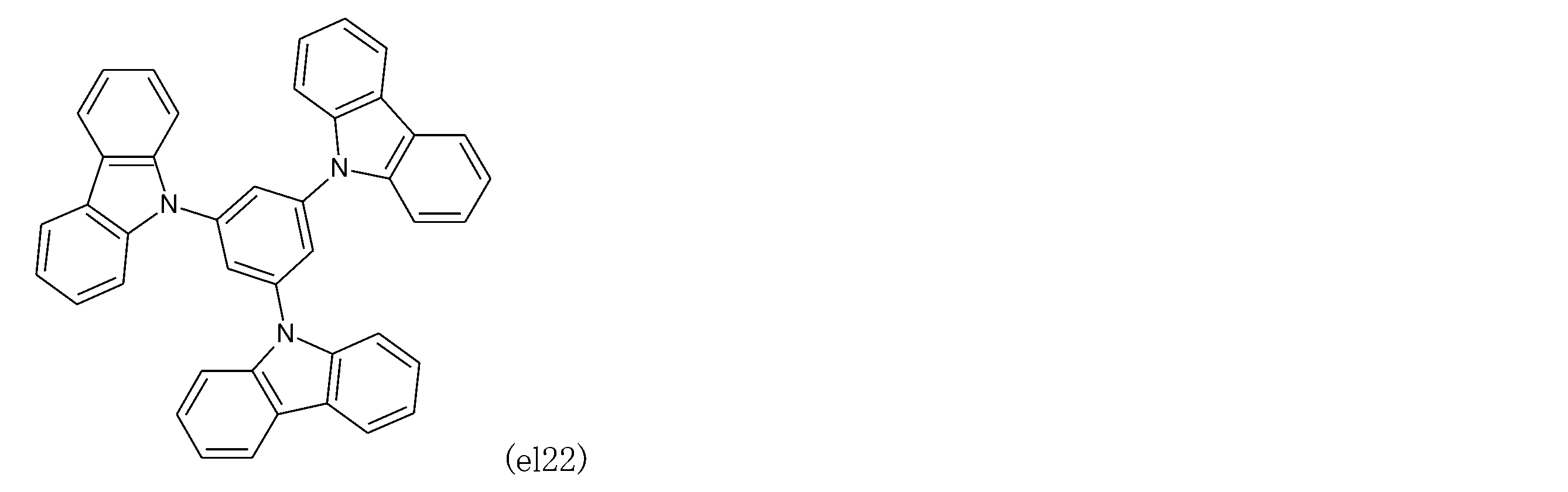
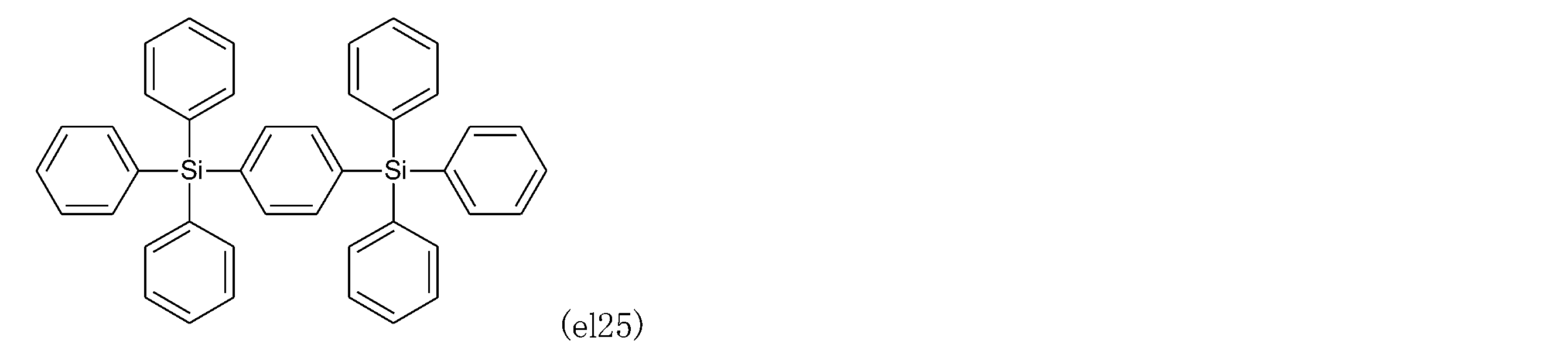
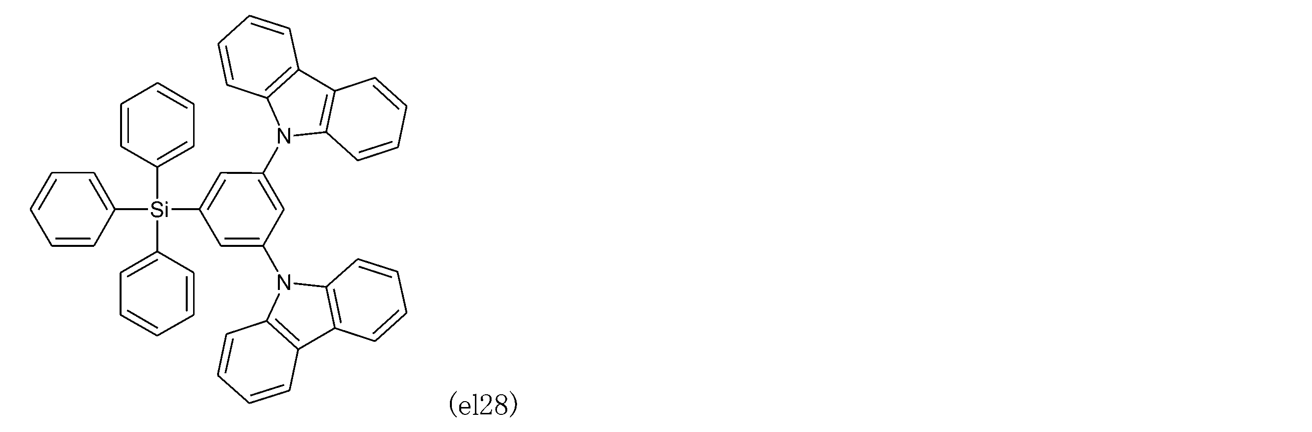
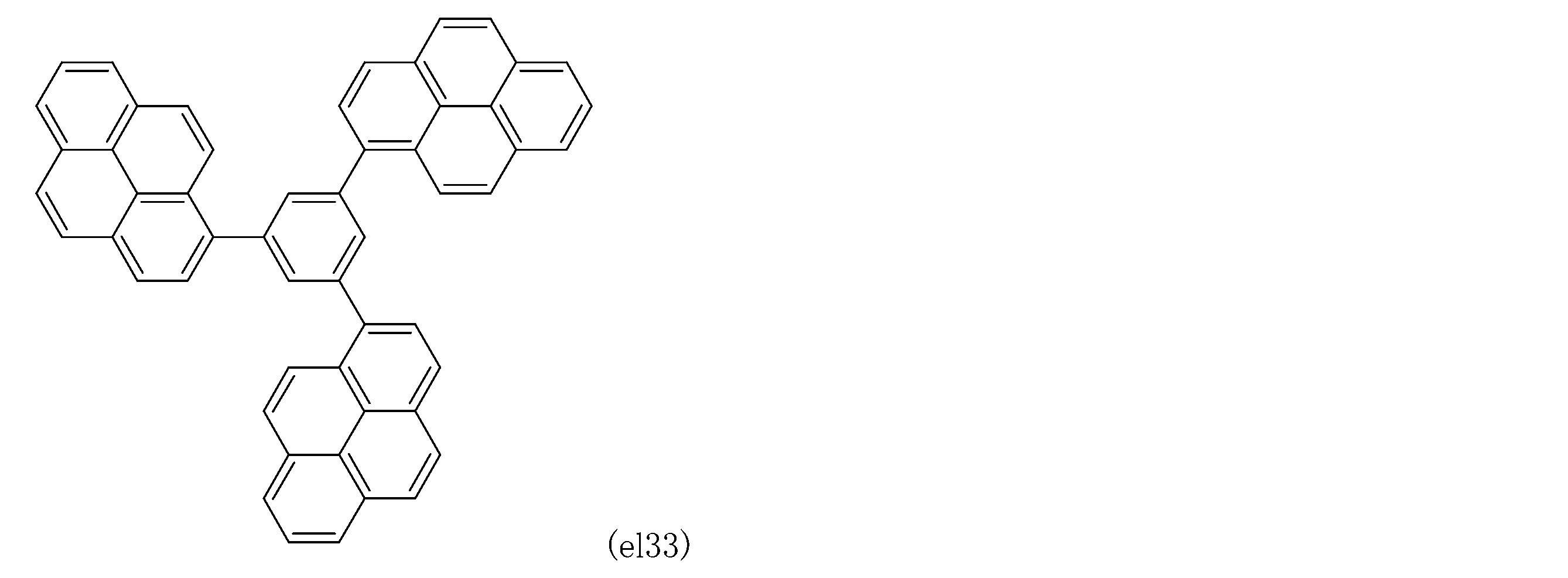
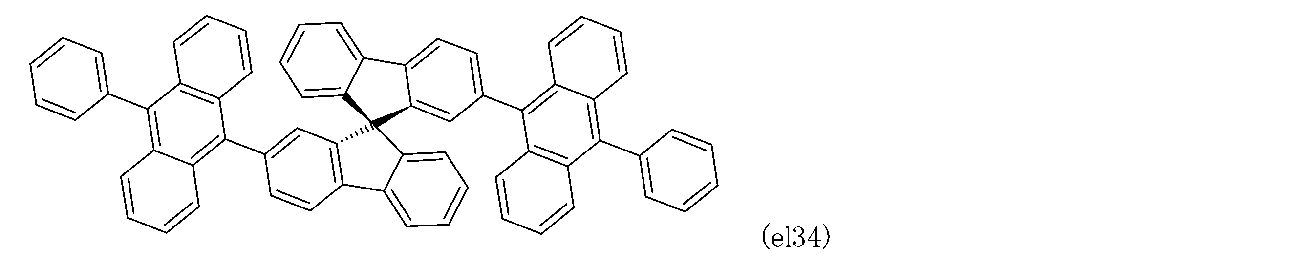
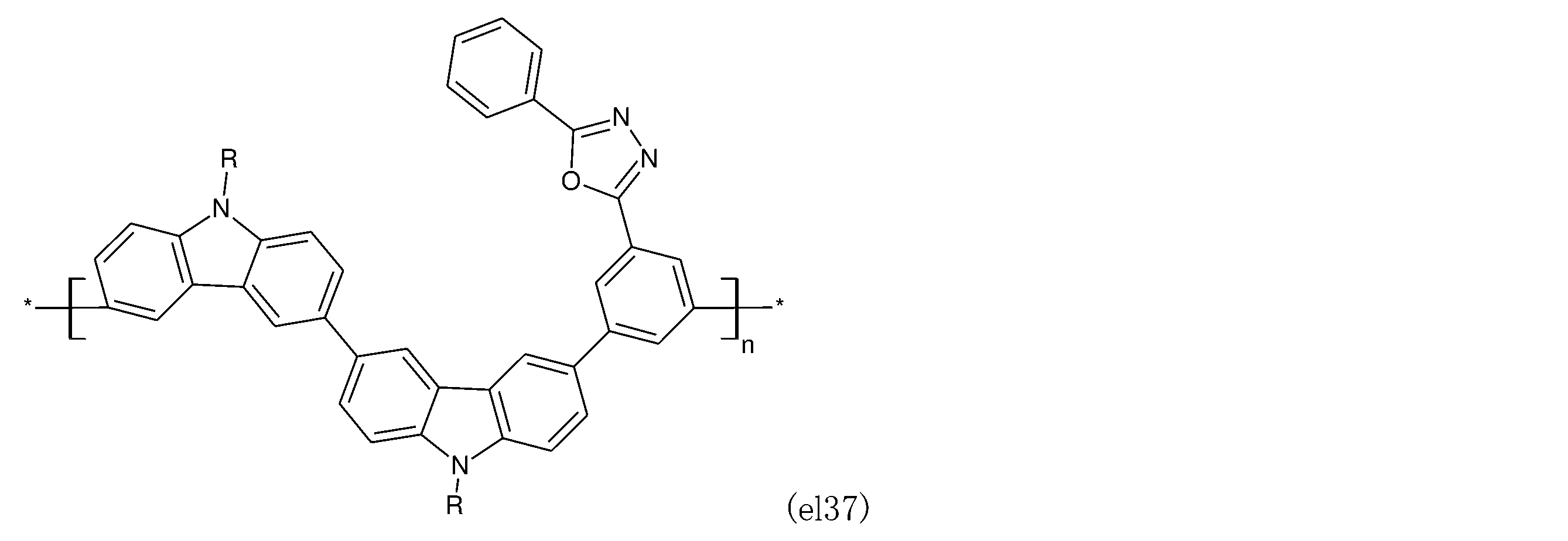
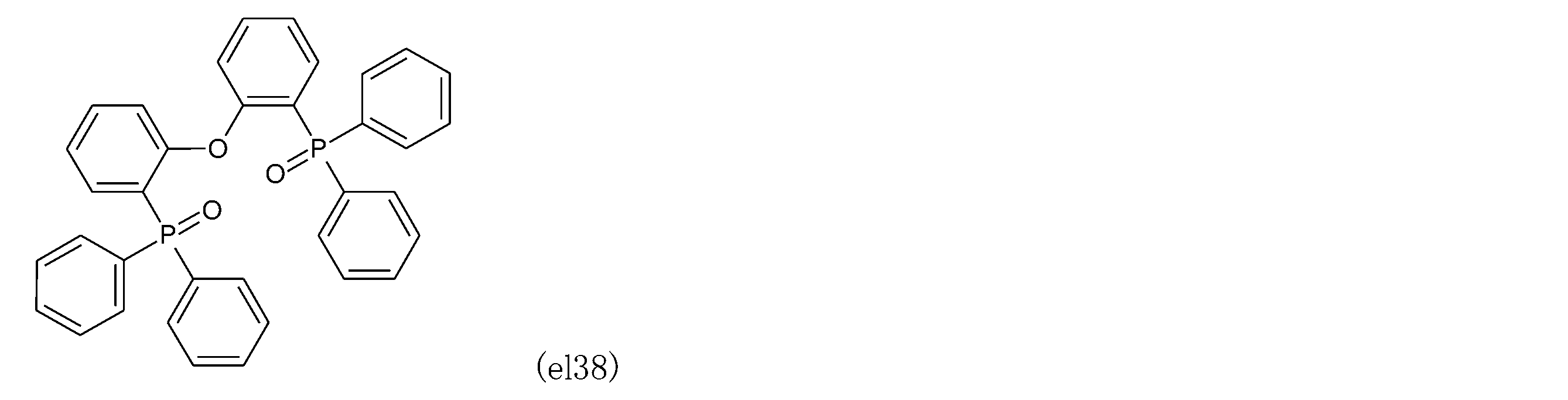
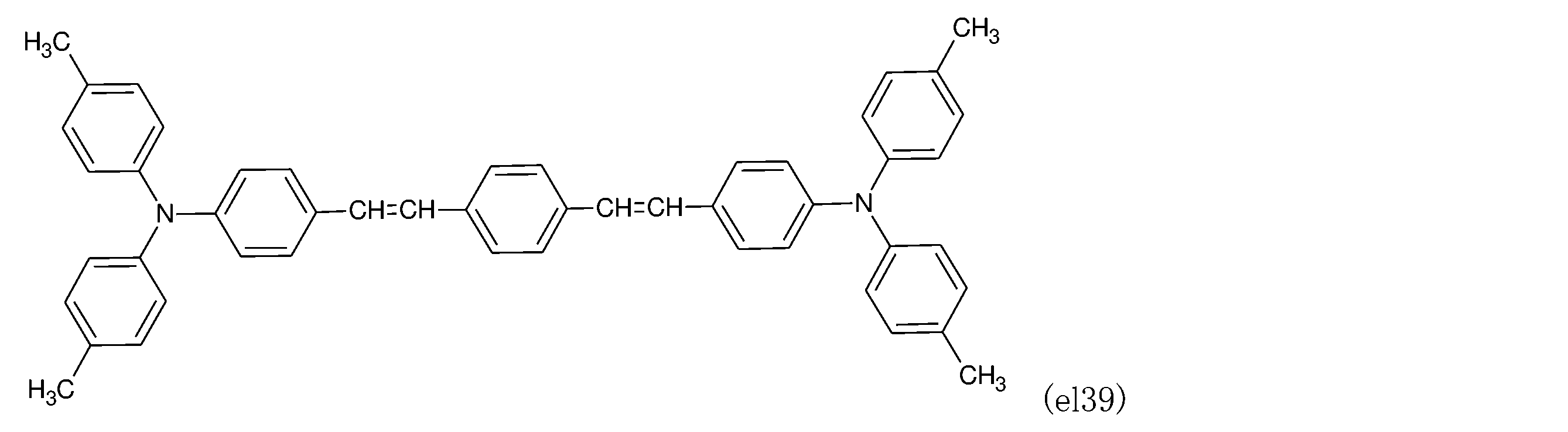
- Preferred compounds (el1) to (el40) that can be used as a host material for the light emitting layer are listed below.
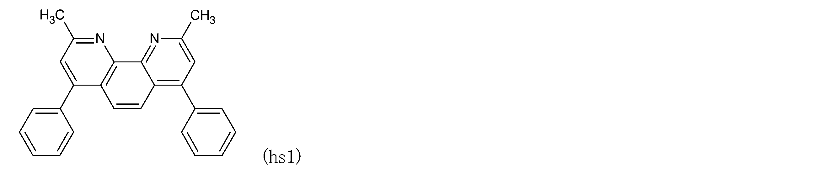
- BCP bassokproin
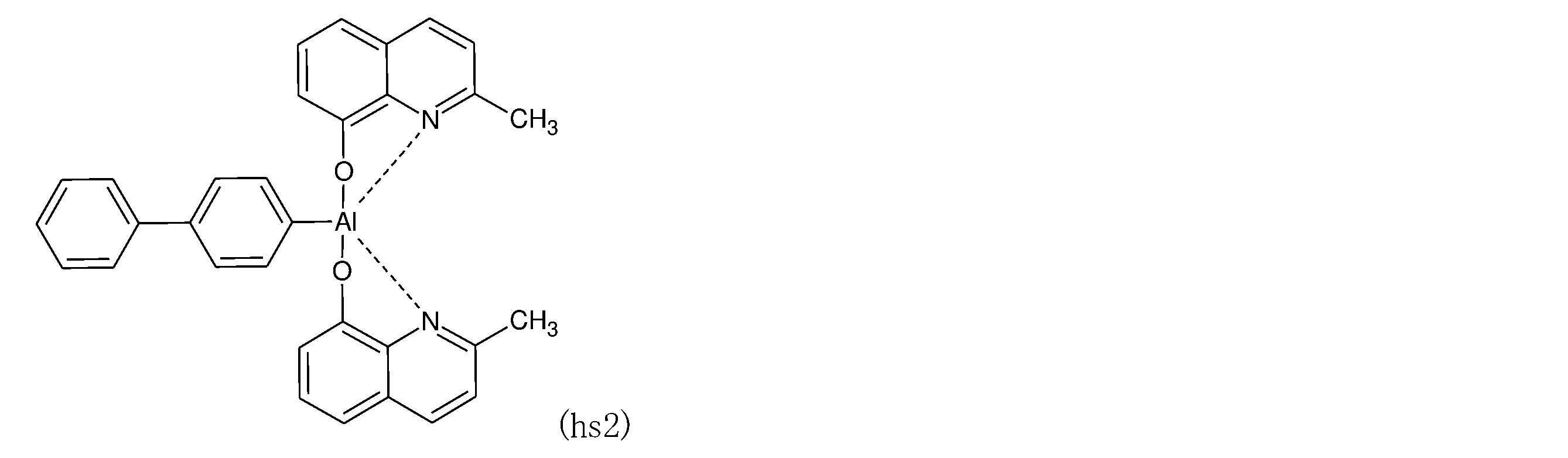
- BCP aluminum (III) bis (2-methyl-8-).
- BAlq a phenanthroline derivative
- BAlq a phenanthroline derivative
- other quinolinol derivative metal complexes various rare earth complexes
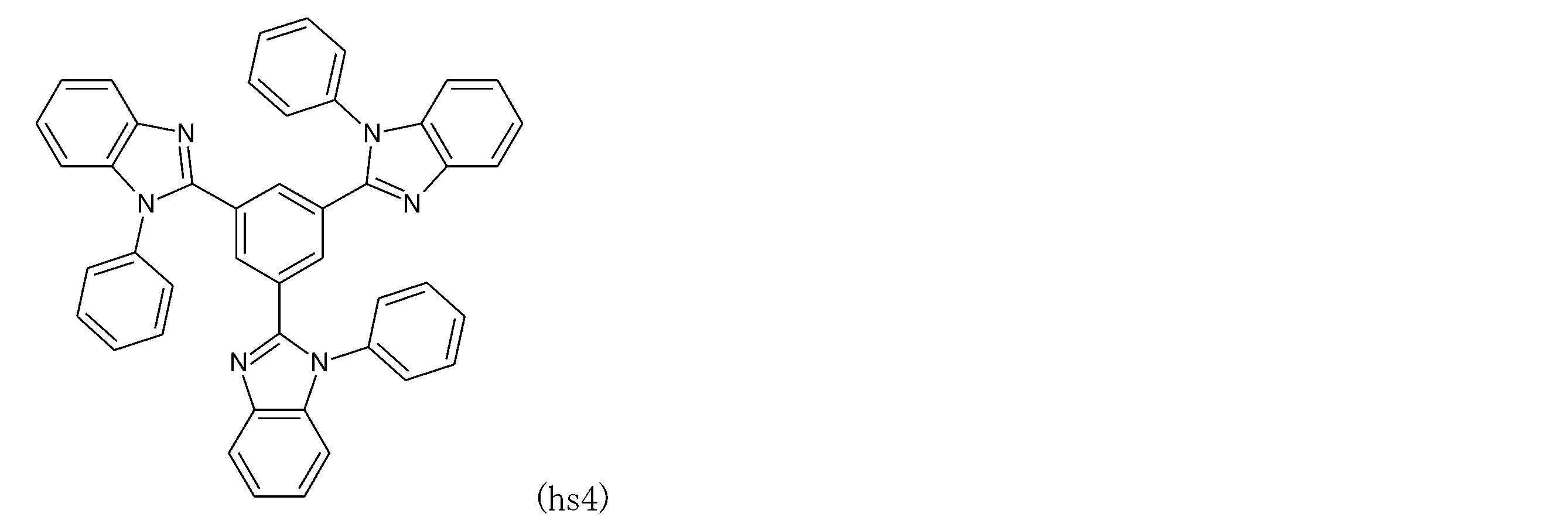
- oxazole derivatives, triazole derivatives, triazine derivatives, and other compounds that have a hole-blocking effect can be mentioned. It can.
- These materials may also serve as materials for the electron transport layer. These can be used alone or in combination of two or more.
- the hole blocking layer may be a single-layered film or a laminated film. In addition to the vapor deposition method, these materials can be thin-filmed by a known method such as a spin coating method or an inkjet method.
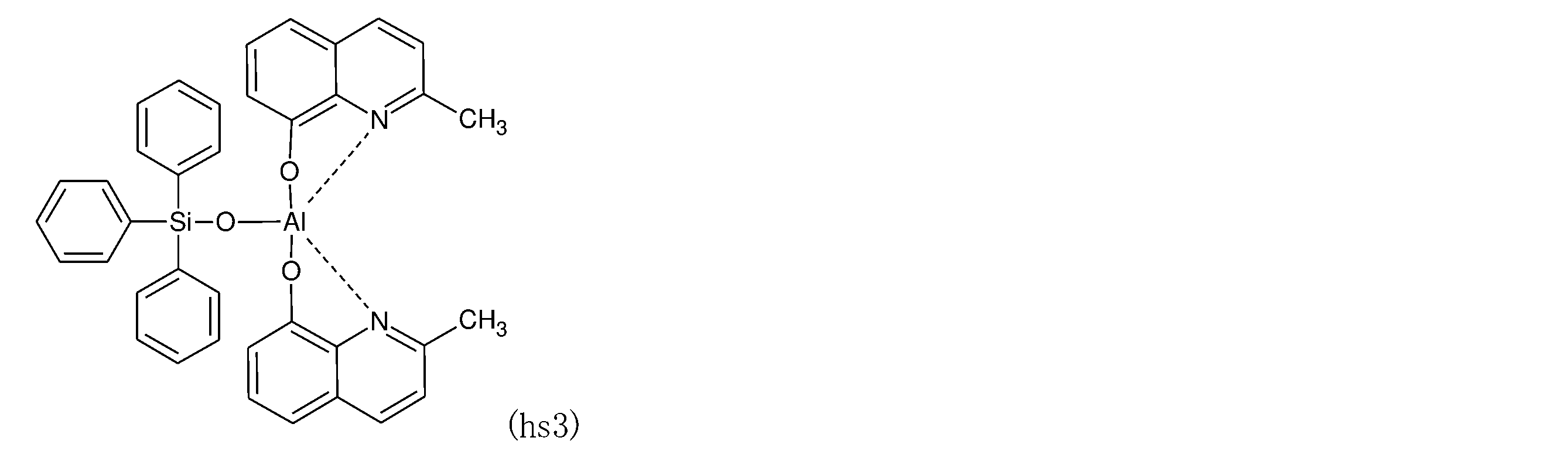
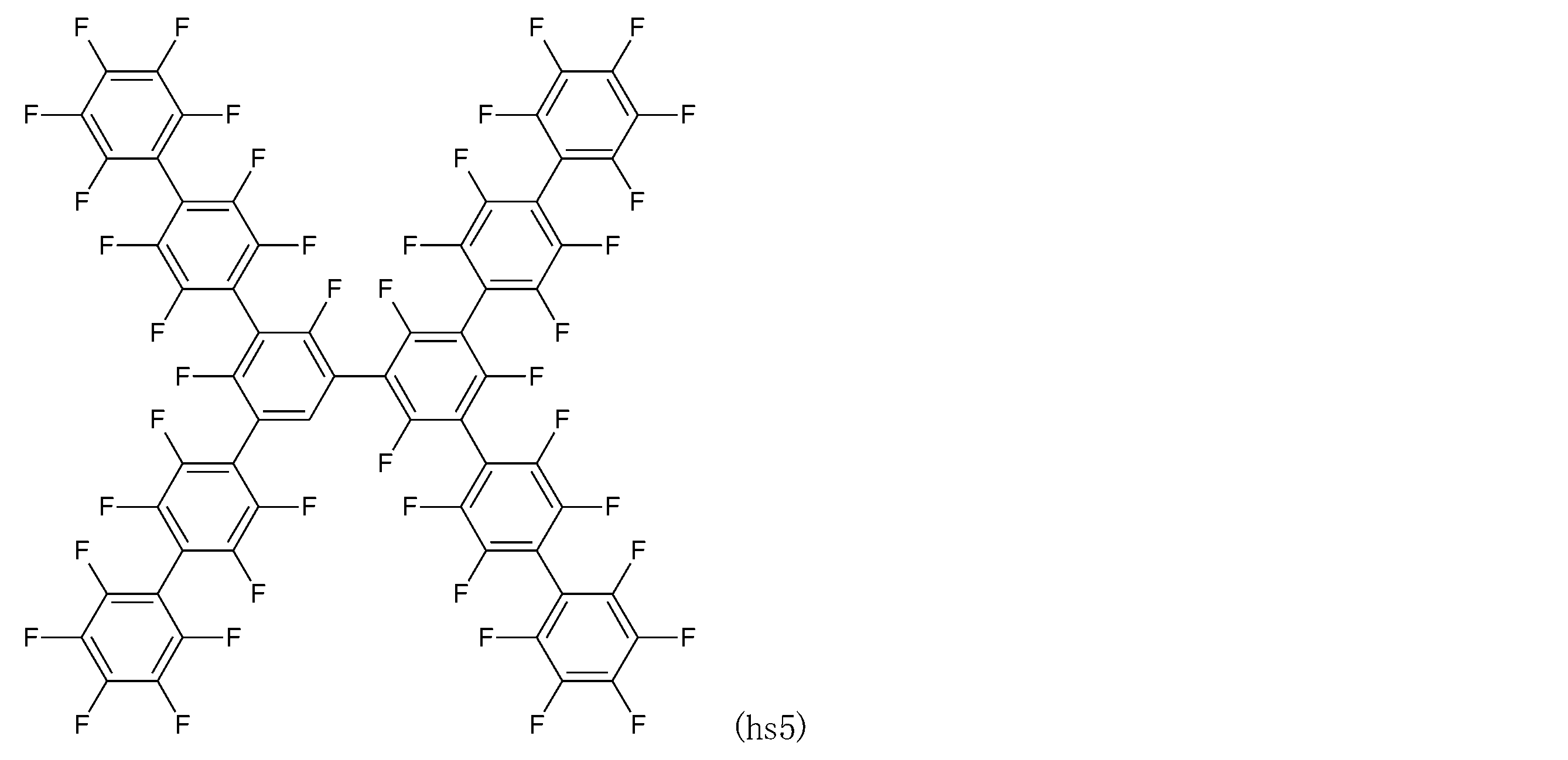
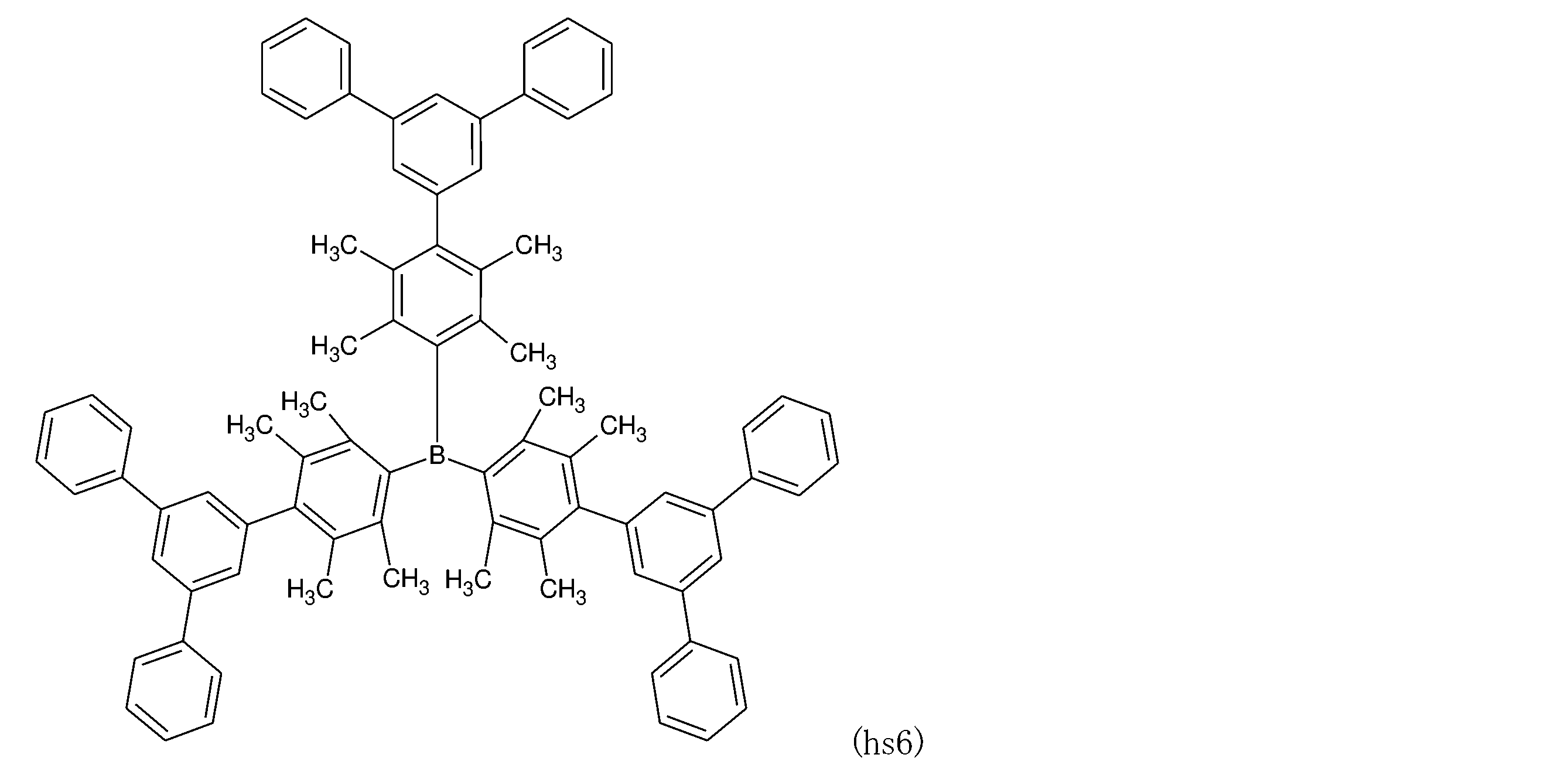
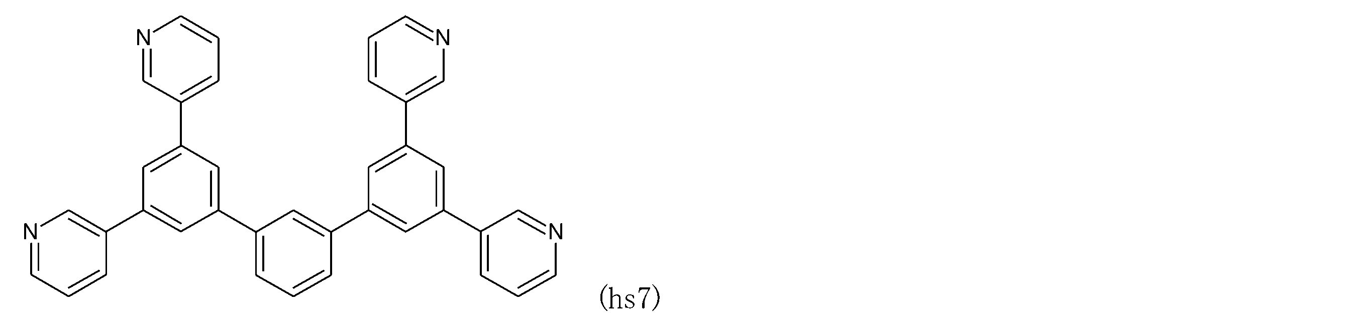
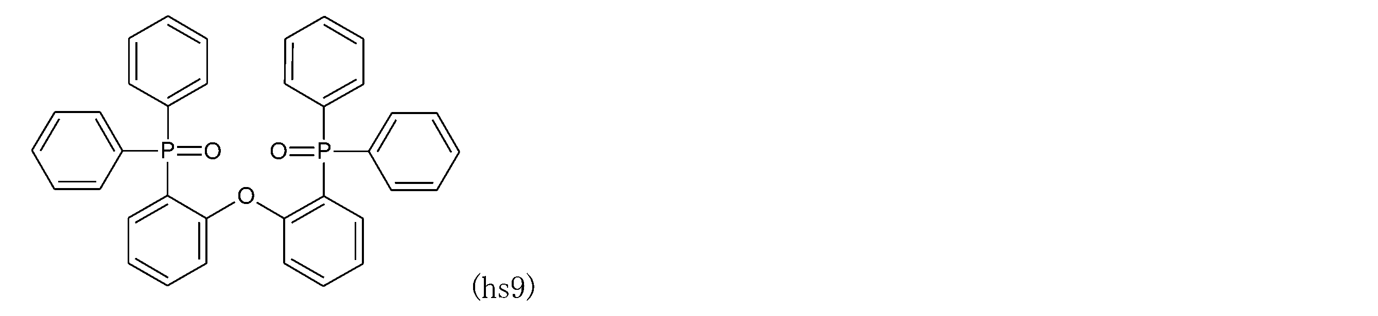
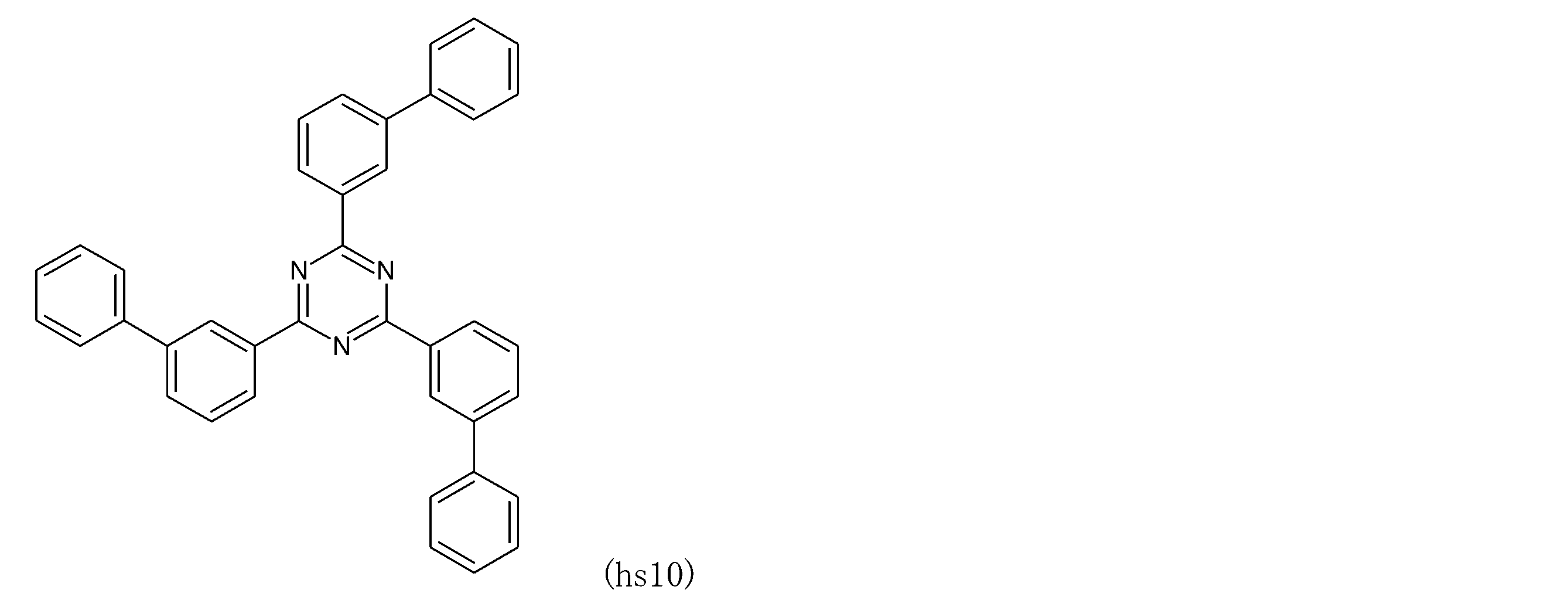
- the preferred compounds (hs1) to (hs11) that can be used as the hole blocking material are listed below.
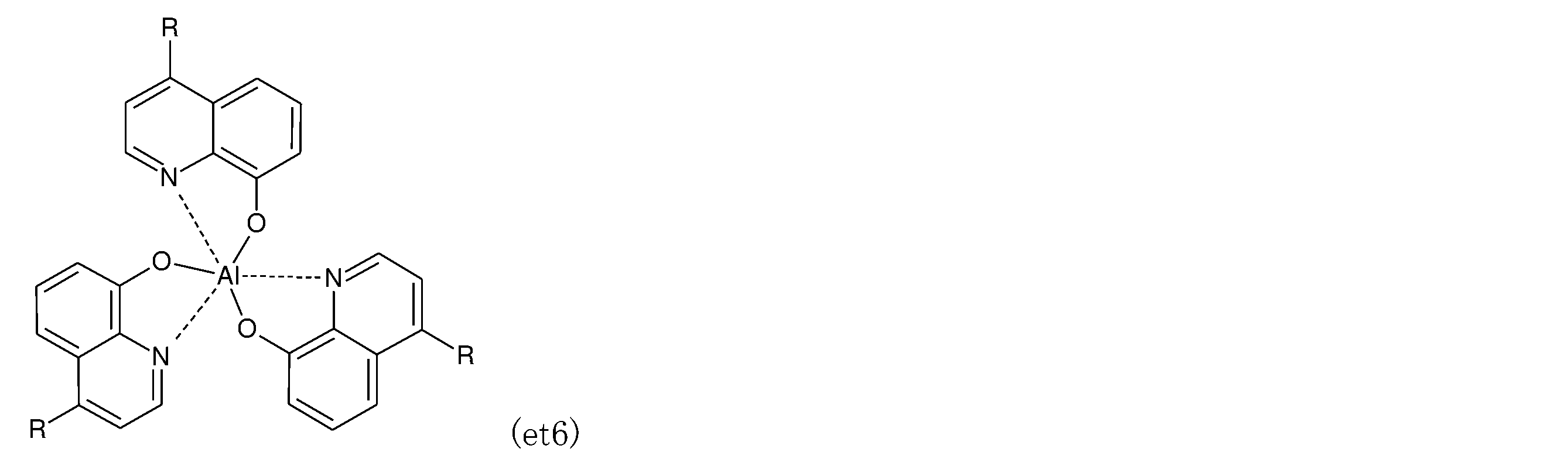
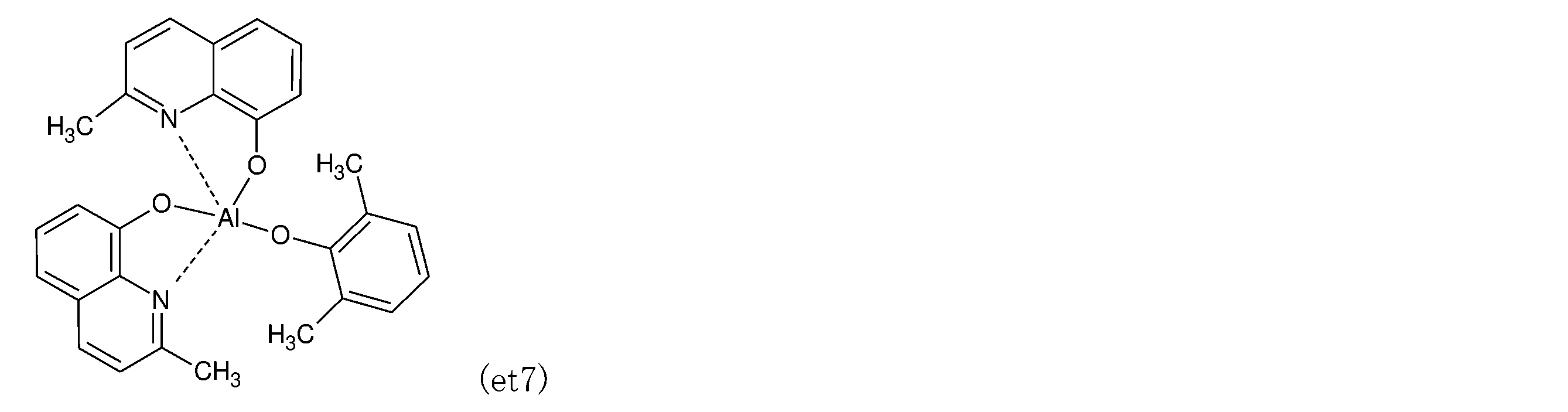
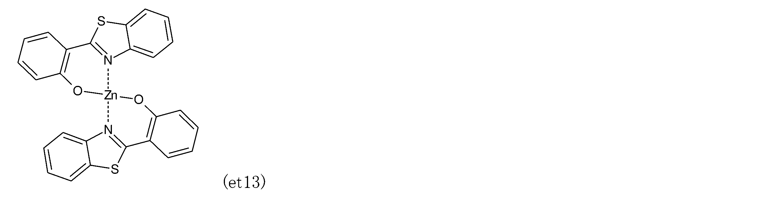
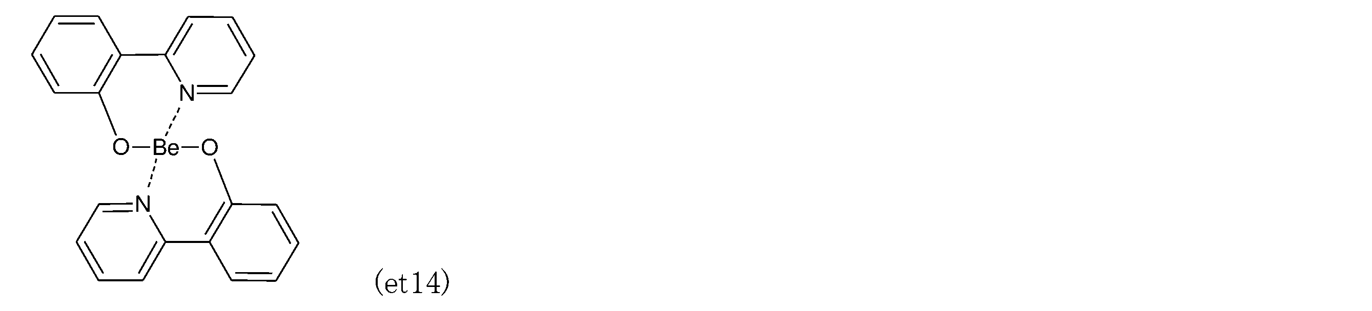
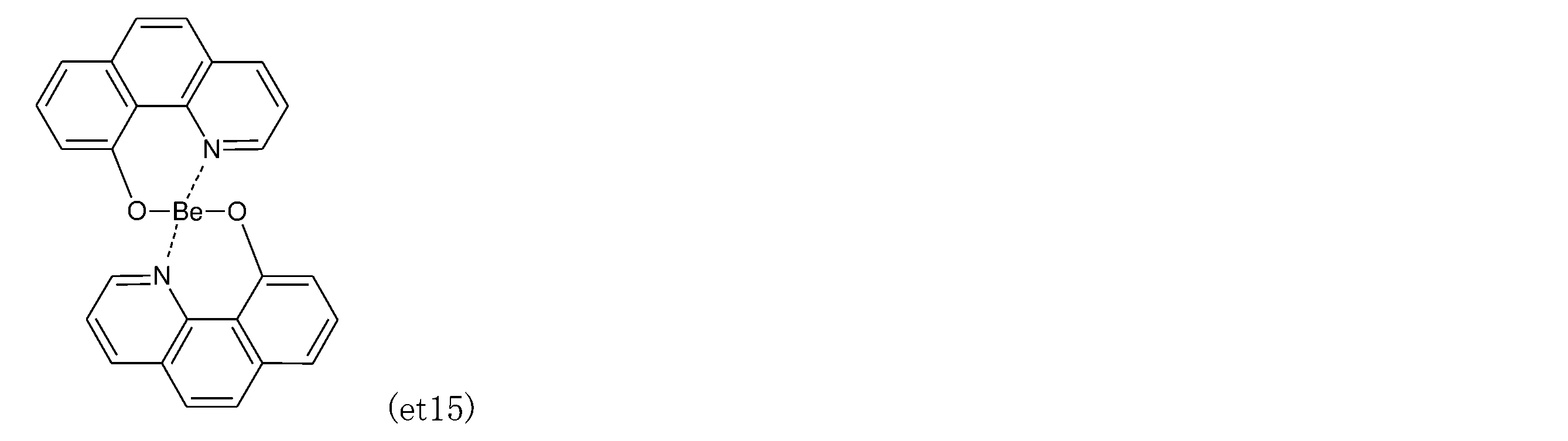
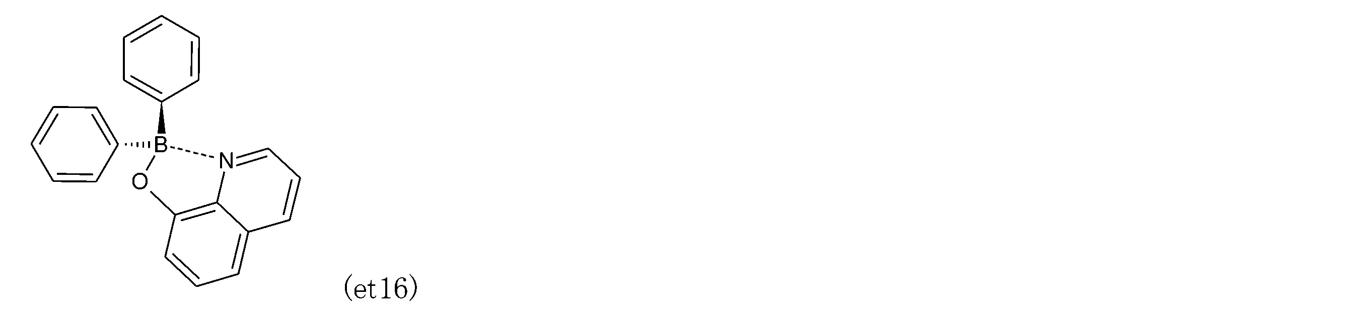
- an electron transporting layer As an electron transporting layer provided as needed, in addition to metal complexes of quinolinol derivatives such as Alq3 and BAlq, various metal complexes, triazole derivatives, triazine derivatives, oxadiazole derivatives, thiadiazol derivatives, carbodiimide derivatives, quinoxalin derivatives A phenanthroline derivative, a silol derivative and the like can be used. These can be used alone or in combination of two or more.
- the electron transport layer may be a single-layer structure film or a laminated structure film. In addition to the vapor deposition method, these materials can be thin-filmed by a known method such as a spin coating method or an inkjet method.
- Alkaline metal salts such as lithium fluoride and cesium fluoride, alkaline earth metal salts such as magnesium fluoride, and metal oxides such as aluminum oxide can be used as the electron injection layer provided as needed. This can be omitted in the preferred choice of electron transport layer and cathode.
- a material usually used for the layer and further N-doped with a metal such as cesium can be used.
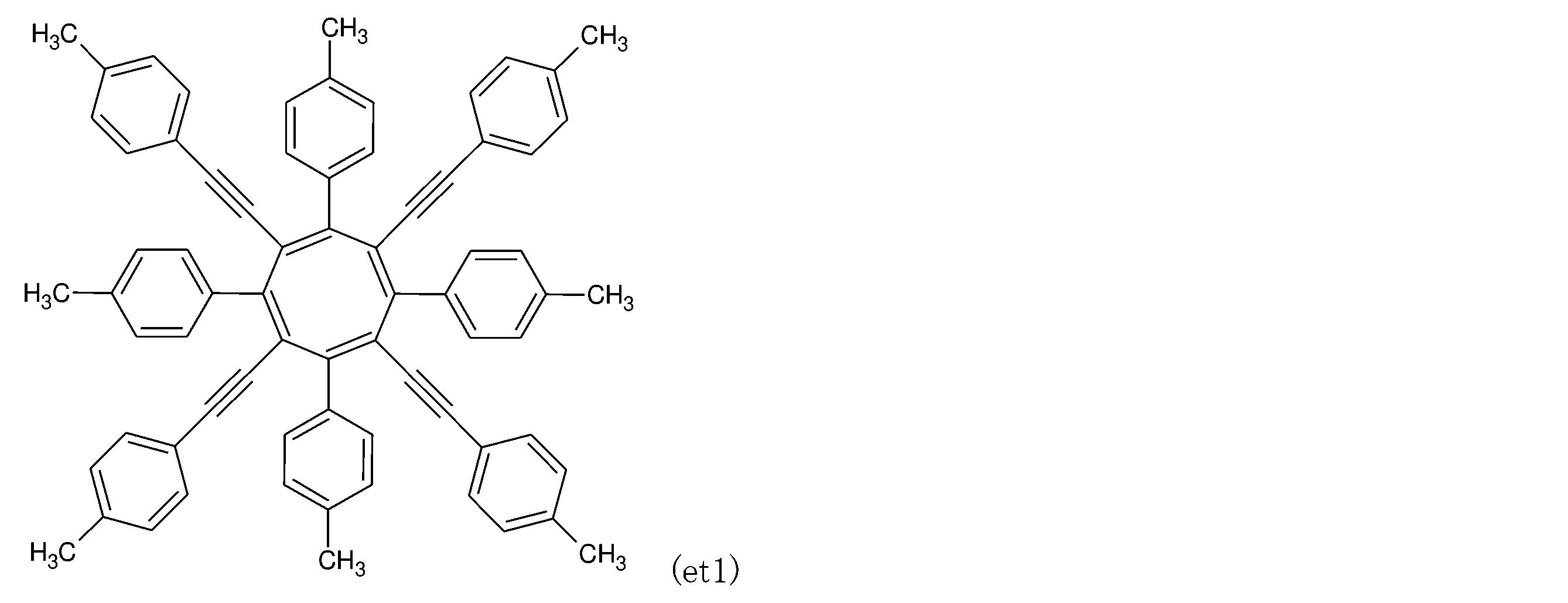
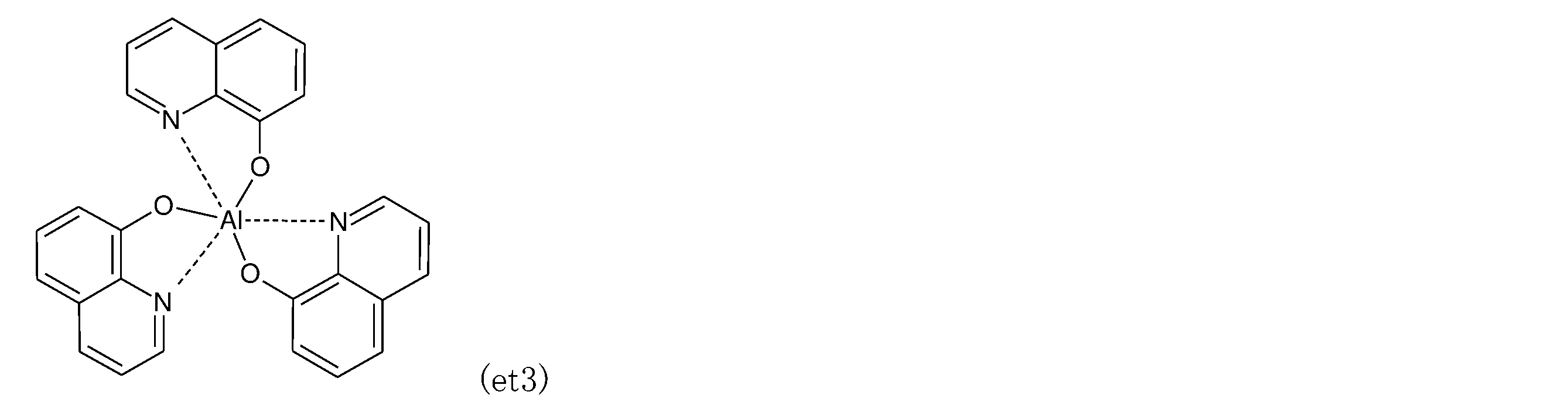
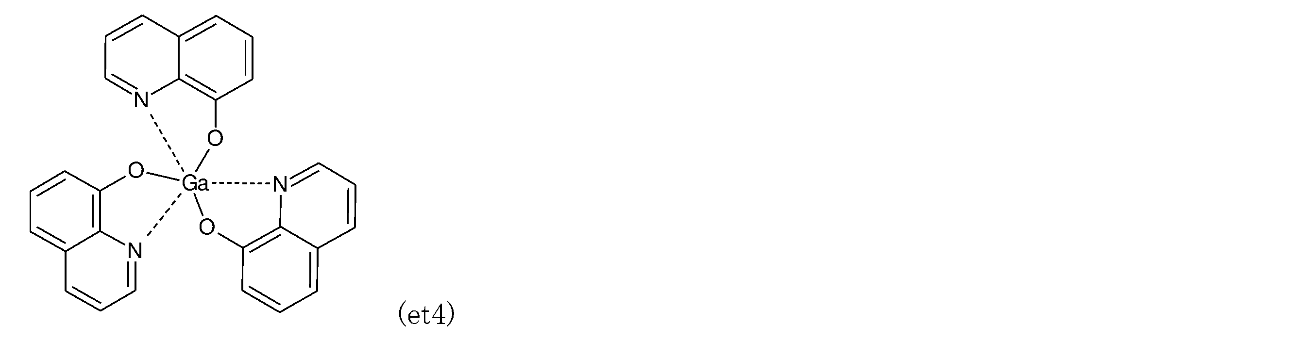
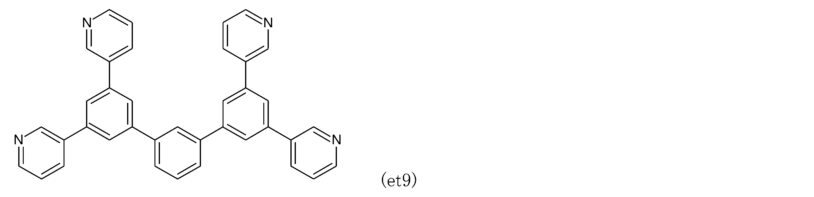
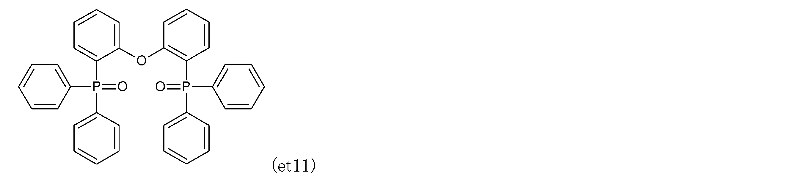
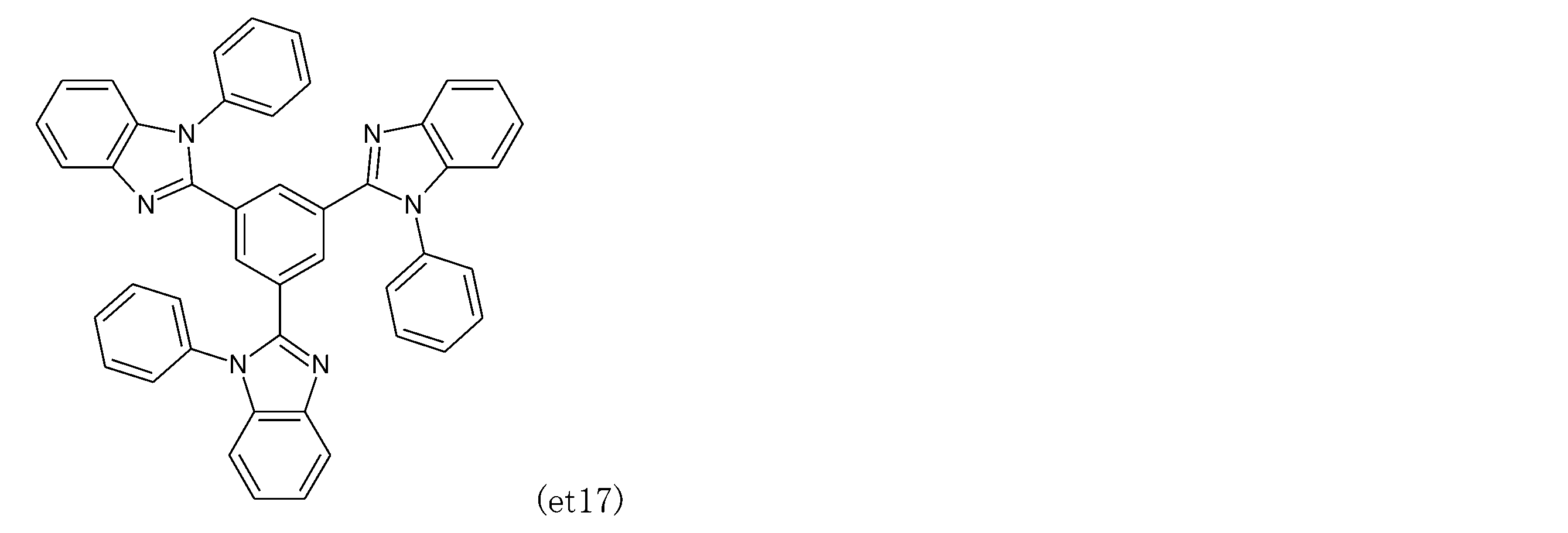
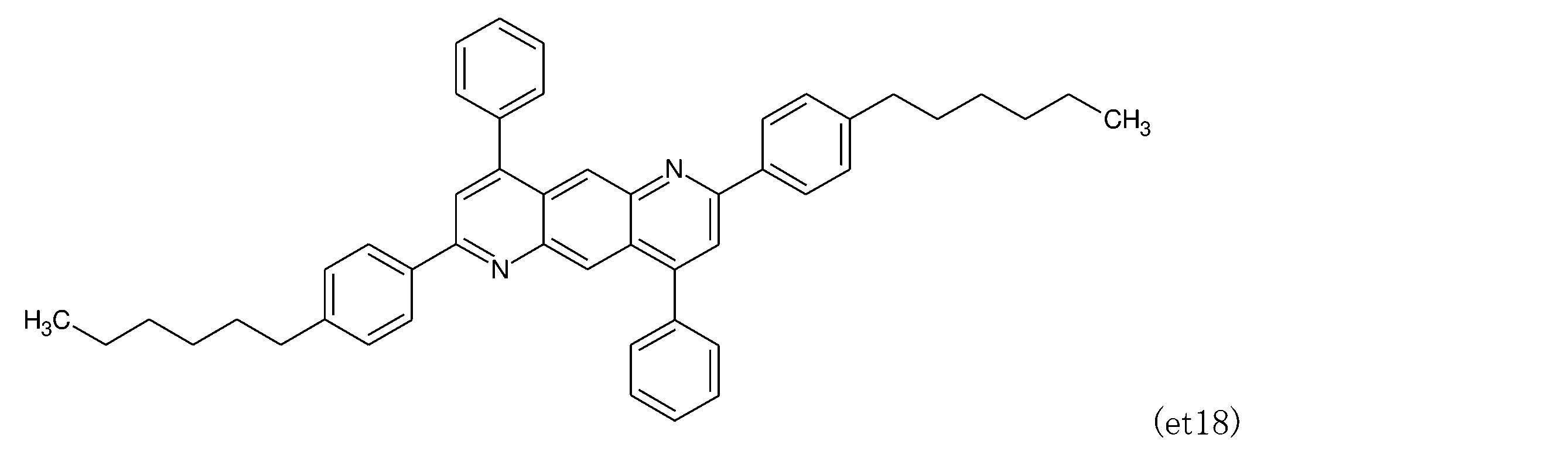
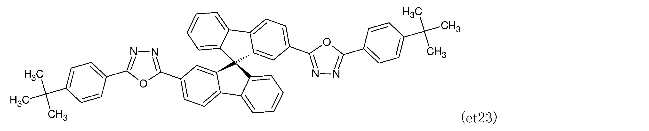
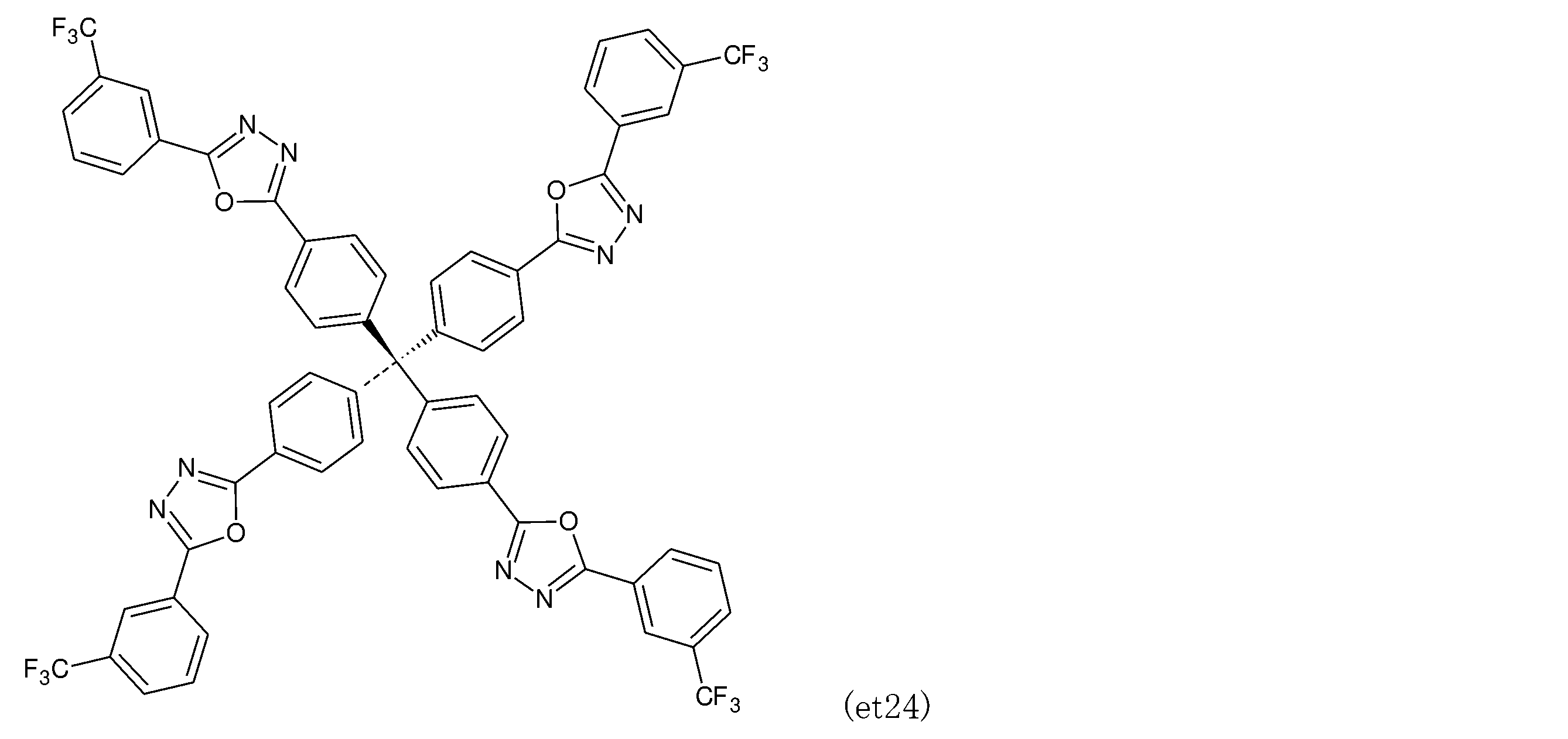
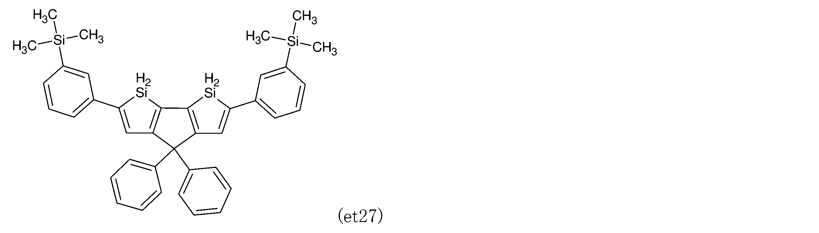
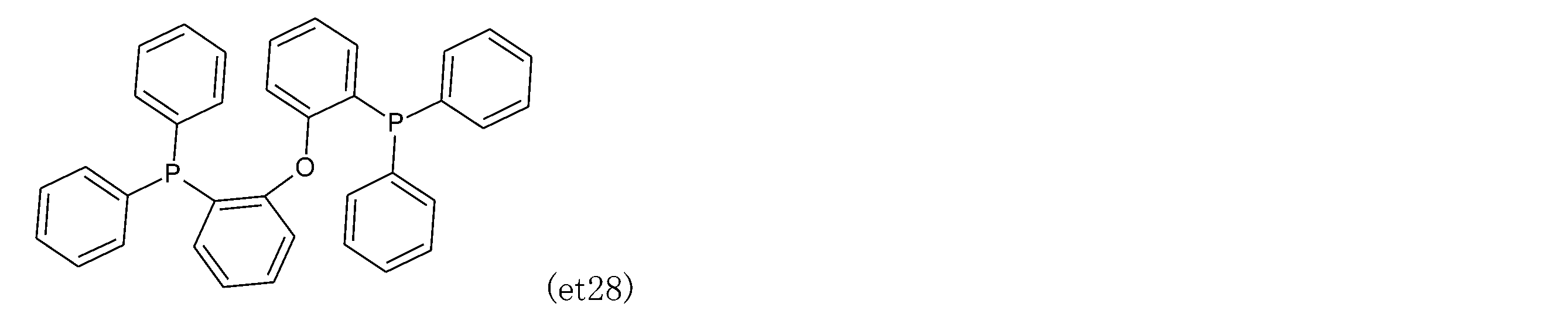
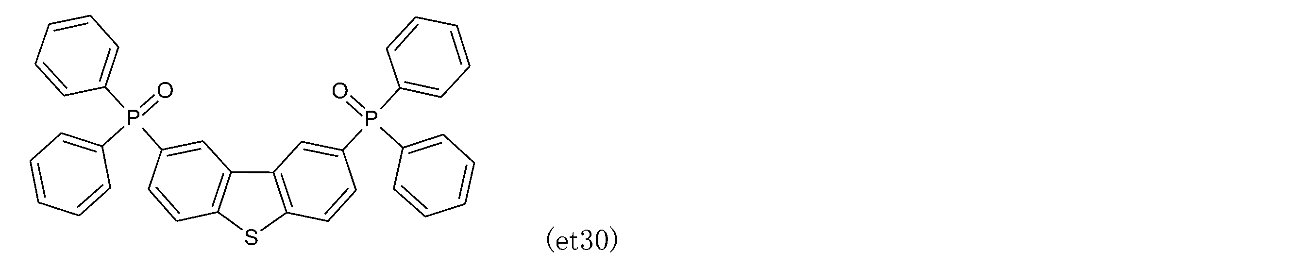
- the preferred compounds (et1) to (et30) that can be used as an electron transport material are listed below.
- the preferred compounds (ei1) to (ei4) that can be used as the electron injection material are listed below.
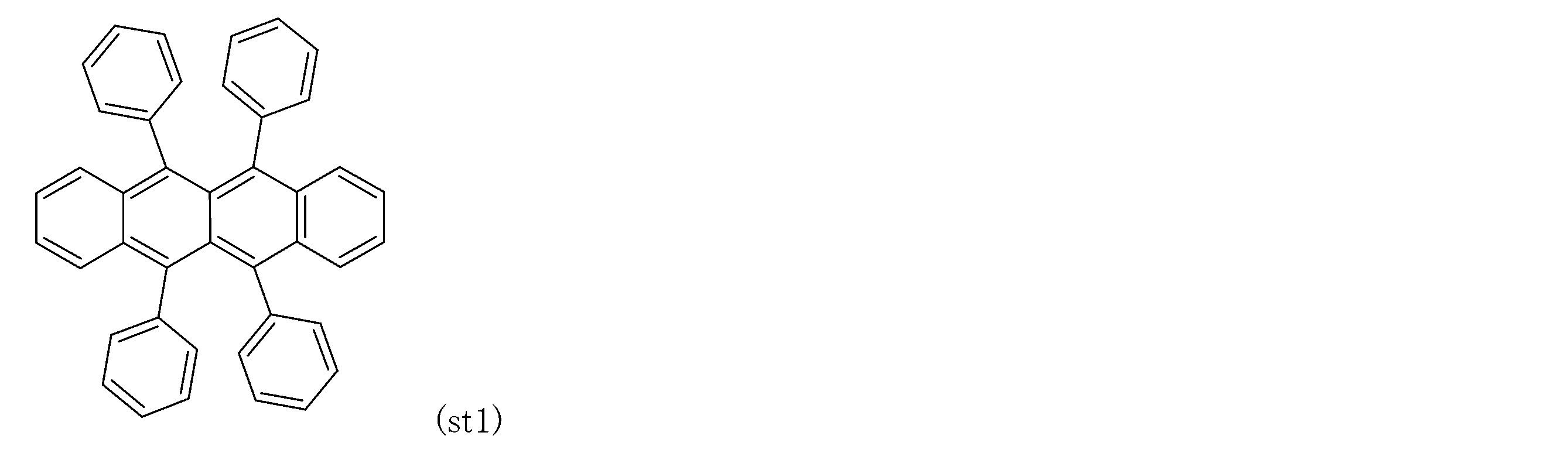
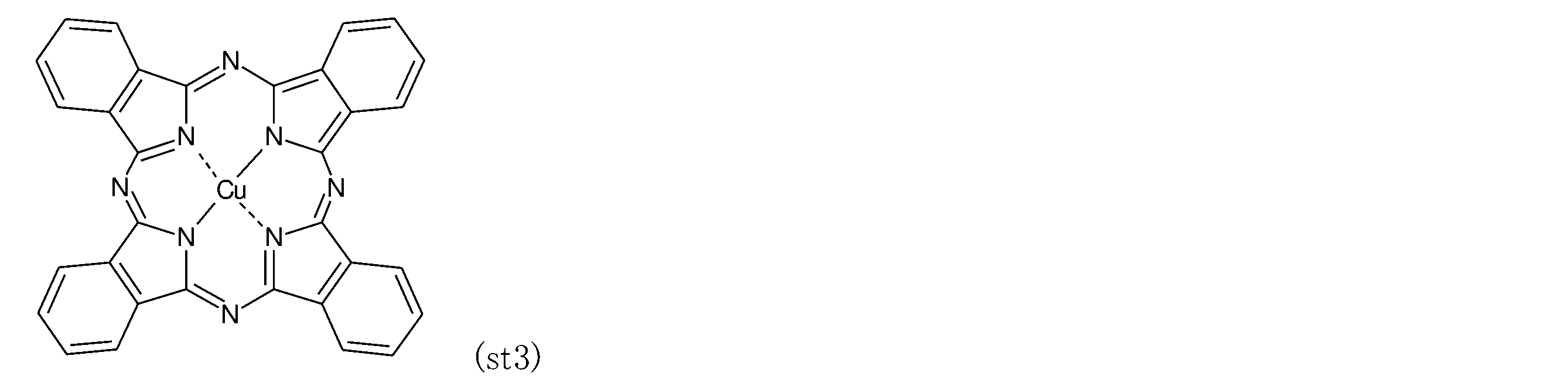
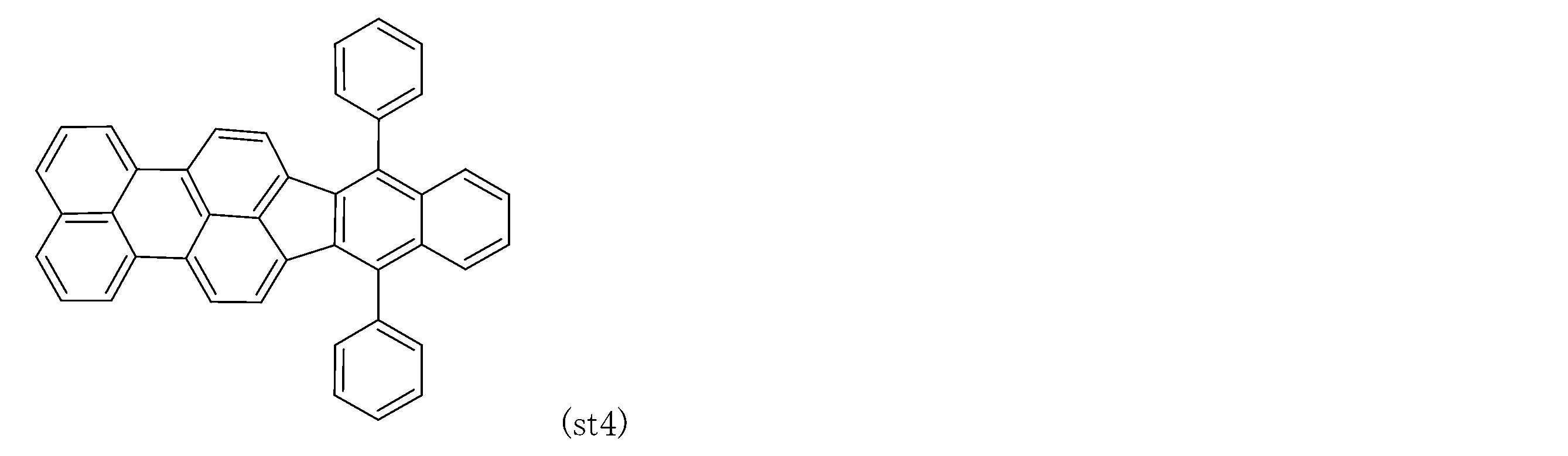
- the preferable compounds (st1) to (st5) that can be used as a stabilizing material are listed below.
- a material with a small work function is generally used for the cathode.
- Materials for cathodes include, for example, sodium, sodium-potassium alloy, lithium, tin, magnesium, magnesium / copper mixture, magnesium / aluminum mixture, magnesium / indium mixture, aluminum / aluminum oxide mixture, indium, calcium, aluminum, silver, lithium. / Aluminum mixture, magnesium silver alloy, magnesium indium alloy, aluminum magnesium alloy, etc. are used.
- a transparent or translucent cathode can be obtained by using a transparent conductive material.
- the thickness of the cathode is usually 10 to 5000 nm, preferably 50 to 200 nm.
- the sheet resistance of the cathode is preferably several hundred ⁇ / ⁇ or more.
- a metal layer having a high work function and stable to the atmosphere such as aluminum, silver, nickel, chromium, gold, and platinum, is further laminated on the cathode. This is preferable because it increases the stability of the device. Further, in order to improve the contact between the cathode and the adjacent organic layer (for example, an electron transport layer or an electron injection layer), a cathode interface layer may be provided between the two.
- Examples of the material used for the cathode interface layer include aromatic diamine compounds, quinacridone compounds, naphthacene derivatives, organosilicon compounds, organophosphorus compounds, compounds having an N-phenylcarbazole skeleton, and N-vinylcarbazole polymers. ..
- the light emitting device of the present invention can be applied to any of a single element, an element having a structure arranged in an array, and a structure in which an anode and a cathode are arranged in an XY matrix.
- an organic photoluminescence device and an organic electroluminescence device were produced, and the light emission characteristics were evaluated. Emission characteristics are evaluated by a source meter (Caseley: 2400 series), a spectral radiance meter (Konica Minolta: CS-2000), a spectral fluorometer (JASCO: FP-8600), and a 100 mm ⁇ integral. This was performed using a sphere (manufactured by JASCO Corporation: ILF-835).
- the reaction solution was cooled with ice water, water and ethyl acetate were added, and the organic layer was separated. Further, the aqueous layer was extracted twice with ethyl acetate, and the mixed organic layer was washed with saturated brine. The organic layer was dehydrated with magnesium sulfate, filtered and concentrated to obtain a crude product.
- the crude product was purified by silica gel column chromatography (eluent: n-hexane / benzene) to obtain a crude product. The crude product was washed with ethyl acetate and filtered, and the solvent was distilled off to obtain 1.21 g of the target compound as a slightly yellowish white solid with a yield of 51.0%.
- Example 4 Toluene solutions of BCz-2PIN, BCz-2IN-I, and BCz-2IN-II (concentration 10-5 M) were prepared in a glove box in a nitrogen atmosphere, respectively, and used as a luminescent material. PL spectra were measured for these luminescent materials. The result is shown in FIG.
- Example 5 HAT-CN (dipyrazino [2,3-F: 2', 3'-H] quinoxalin-2, 10 nm thick on a glass substrate on which an anode made of indium tin oxide (ITO) having a thickness of 50 nm was formed.
- ITO indium tin oxide
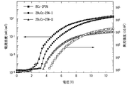
- FIG. 2 shows the voltage-current density-emission intensity characteristics.
- black marks indicate current density
- white marks indicate emission intensity.
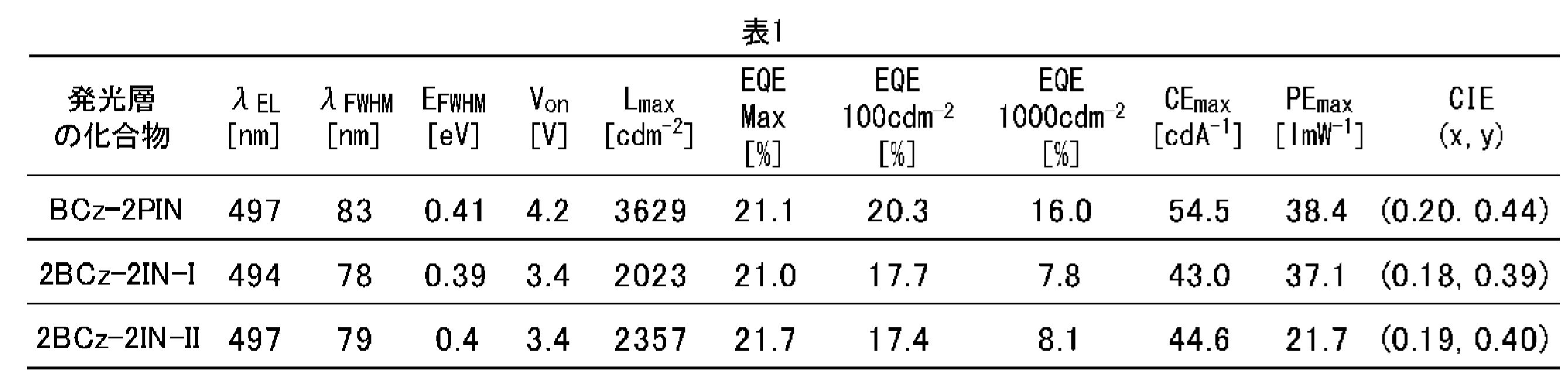
- FIG. 3 shows the current density-external quantum efficiency characteristics. Other results are shown in Table 1.
- Example 9 Toluene solutions of Ph-BiCz-PIN, BiCz-2PIN, and PCz-PIN (concentration 10-5 M) were prepared in a nitrogen-like glove box and used as a luminescent material. PL spectra were measured for these luminescent materials. The result is shown in FIG.
- Example 10 A 10 nm thick HAT-CN layer, a 40 nm thick TAPC layer, a 10 nm thick CCP layer, a 10 nm thick mCP layer, and 20 nm on a glass substrate on which an anode made of indium tin oxide (ITO) having a thickness of 50 nm is formed.
- ITO indium tin oxide
- a thick light emitting layer, a 10 nm thick PPF layer, and a 40 nm thick B3PyPBM layer were laminated in this order by a vacuum vapor deposition method (5.0 ⁇ 10 -4 Pa or less).
- FIG. 5 shows the voltage-current density-emission intensity characteristics.
- black marks indicate current density
- white marks indicate emission intensity.
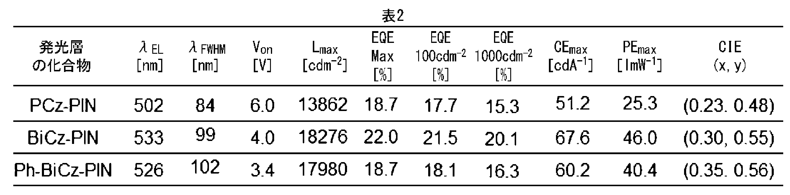
- FIG. 6 shows the current density-external quantum efficiency characteristics. Other results are shown in Table 2.
- the light emitting material made of the compound of the present invention obtained high light emitting characteristics.
- the isophthalonitrile compound according to the present invention is useful as a light emitting material.
- the light emitting device containing the light emitting material according to the present invention can realize excellent luminous efficiency.
Landscapes
- Chemical & Material Sciences (AREA)
- Organic Chemistry (AREA)
- Engineering & Computer Science (AREA)
- Materials Engineering (AREA)
- Physics & Mathematics (AREA)
- Optics & Photonics (AREA)
- Spectroscopy & Molecular Physics (AREA)
- Electroluminescent Light Sources (AREA)
- Plural Heterocyclic Compounds (AREA)
- Indole Compounds (AREA)
Abstract
Description
本願は、2019年6月14日に、日本に出願された特願2019-111304号に基づき優先権を主張し、その内容をここに援用する。
〔1〕 式(I)、式(II)または式(III)で表される化合物。
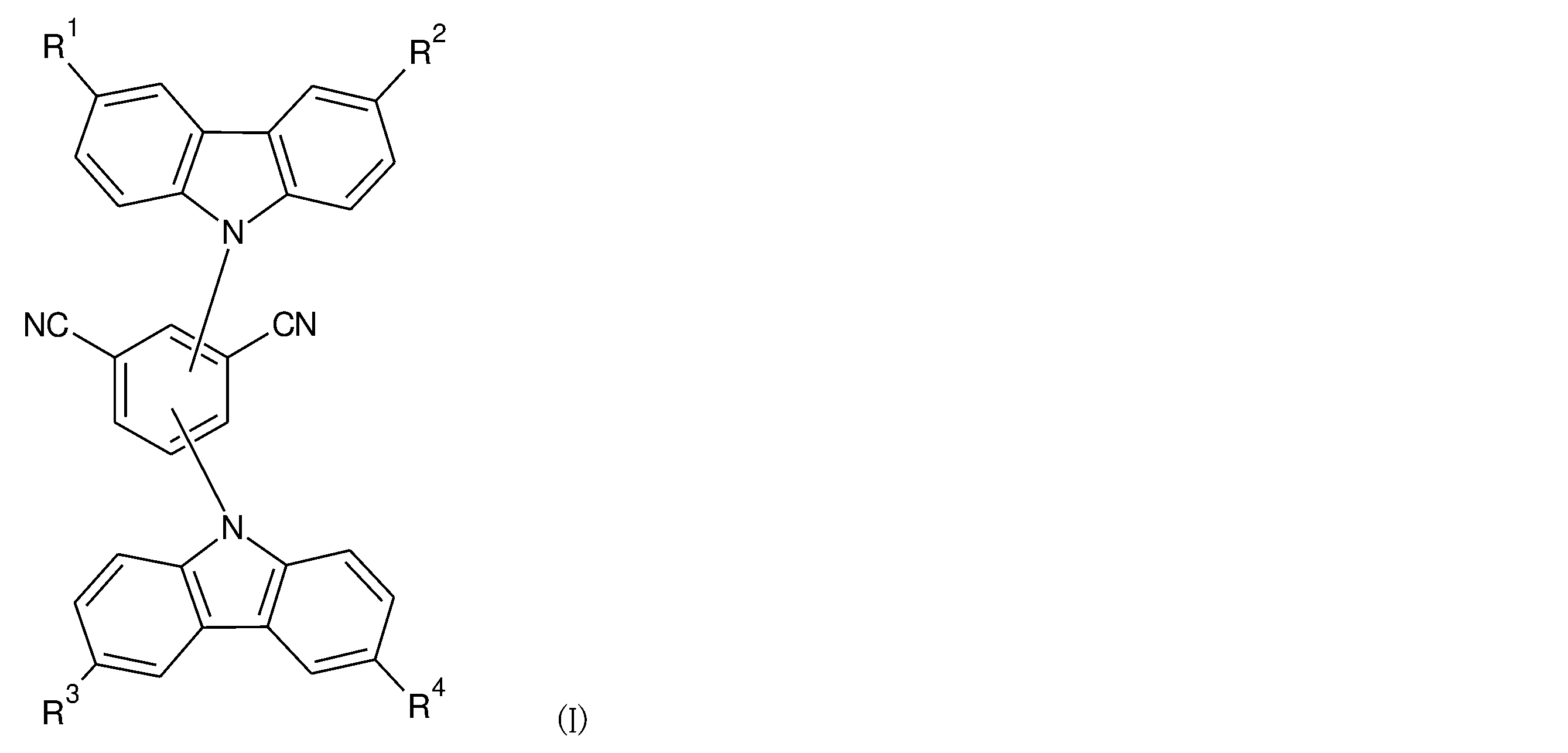
R1、R2、R3およびR4は、それぞれ独立して、水素原子、アルキル基、またはヘテロアリール基であり、且つR1、R2、R3およびR4が同時に水素原子であることはない。

R5およびR6は、それぞれ独立して、水素原子、アルキル基、アリール基、またはヘテロアリール基であり、R5およびR6が同時に水素原子であることはなく、
L1およびL2は、それぞれ独立して、アリール基である。

R7、R8、R9およびR10は、それぞれ独立して、水素原子、アリール基、またはヘテロアリール基であり、R7、R8、R9およびR10が同時に水素原子であることはなく、且つ
L1、およびL2は、それぞれ独立して、アリール基である。
〔3〕 〔2〕に記載の発光材料を含有する発光素子。
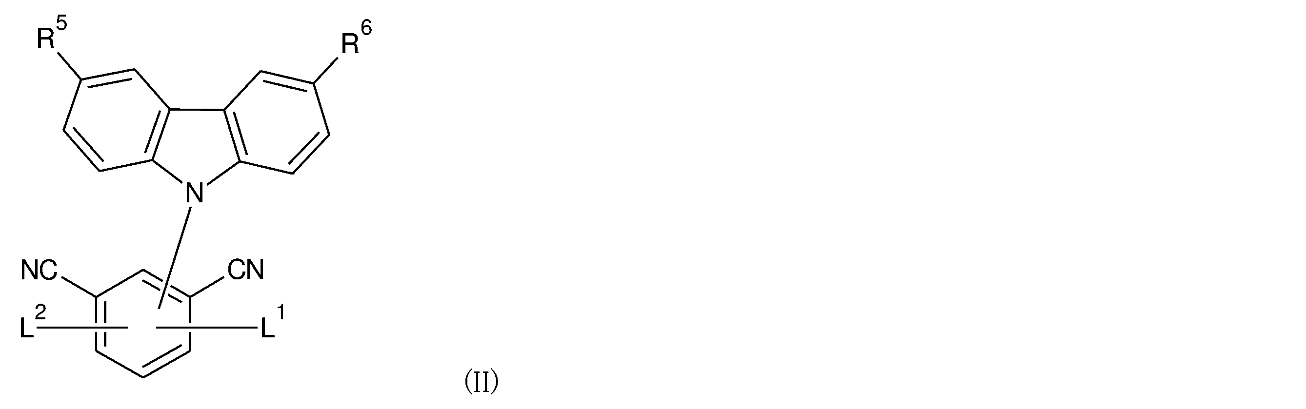
式(II)中、L1およびL2は、それぞれ独立して、アリール基である。

式(III)中、L1およびL2は、それぞれ独立して、アリール基である。
一方、用語「置換(substituted)」は、母核となる基のいずれかの水素原子が、母核と同一または異なる構造の基で置換されていることを意味する。従って、「置換基」は、母核となる基に結合した他の基である。置換基は1個であってもよいし、2個以上であってもよい。2個以上の置換基は同一であってもよいし、異なるものであってもよい。
「置換基」となり得る基の具体例としては、以下の基を挙げることができる。
フルオロ基、クロロ基、ブロモ基、イオド基などのハロゲノ基;
メチル基、エチル基、n-プロピル基、i-プロピル基、n-ブチル基、s-ブチル基、i-ブチル基、t-ブチル基、n-ペンチル基、n-ヘキシル基などのC1~6アルキル基;
ビニル基、1-プロペニル基、2-プロペニル基、1-ブテニル基、2-ブテニル基、3-ブテニル基、1-メチル-2-プロペニル基、2-メチル-2-プロペニル基、1-ペンテニル基、2-ペンテニル基、3-ペンテニル基、4-ペンテニル基、1-メチル-2-ブテニル基、2-メチル-2-ブテニル基、1-ヘキセニル基、2-ヘキセニル基、3-ヘキセニル基、4-ヘキセニル基、5-ヘキセニル基などのC2~6アルケニル基;
シクロプロピル基、シクロブチル基、シクロペンチル基、シクロヘキシル基、シクロヘプチル基、キュバニル基などのC3~8シクロアルキル基;
2-シクロプロペニル基、2-シクロペンテニル基、3-シクロヘキセニル基、4-シクロオクテニル基などのC3~8シクロアルケニル基;
フェニル基、ナフチル基などのC6~10アリール基;
ピロリル基、フリル基、チエニル基、イミダゾリル基、ピラゾリル基、オキサゾリル基、イソオキサゾリル基、チアゾリル基、イソチアゾリル基、トリアゾリル基、オキサジアゾリル基、チアジアゾリル基、テトラゾリル基などの5員環のヘテロアリール基;
ピリジル基、ピラジニル基、ピリミジニル基、ピリダジニル基、トリアジニル基などの6員環のヘテロアリール基;
インドリル基、ベンゾフリル基、ベンゾチエニル基、ベンゾイミダゾリル基、ベンゾオキサゾリル基、ベンゾチアゾリル基、キノリル基、イソキノリル基、キノキサリニル基などの縮合環のヘテロアリール基;
オキシラニル基、テトラヒドロフリル基、ジオキソラニル基、ジオキラニル基などの環状エーテル基;
アジリジニル基、ピロリジニル基、ピペリジル基、ピペラジニル基、モルホリニル基などの環状アミノ基;
メトキシ基、エトキシ基、n-プロポキシ基、i-プロポキシ基、n-ブトキシ基、s-ブトキシ基、i-ブトキシ基、t-ブトキシ基などのC1~6アルコキシ基;
ビニルオキシ基、アリルオキシ基、プロペニルオキシ基、ブテニルオキシ基などのC2~6アルケニルオキシ基;
エチニルオキシ基、プロパルギルオキシ基などのC2~6アルキニルオキシ基;
フェノキシ基、ナフトキシ基などのC6~10アリールオキシ基;
チアゾリルオキシ基、ピリジルオキシ基などの5~6員環のヘテロアリールオキシ基;
ホルミル基; アセチル基、プロピオニル基などのC1~6アルキルカルボニル基;
ホルミルオキシ基; アセチルオキシ基、プロピオニルオキシ基などのC1~6アルキルカルボニルオキシ基;
メトキシカルボニル基、エトキシカルボニル基、n-プロポキシカルボニル基、i-プロポキシカルボニル基、n-ブトキシカルボニル基、t-ブトキシカルボニル基などのC1~6アルコキシカルボニル基;
2-クロロ-1-プロペニル基、2-フルオロ-1-ブテニル基などのC2~6ハロアルケニル基;
4,4-ジクロロ-1-ブチニル基、4-フルオロ-1-ペンチニル基、5-ブロモ-2-ペンチニル基などのC2~6ハロアルキニル基;
3,3-ジフルオロシクロブチル基などのC3~6ハロシクロアルキル基;
2-クロロ-n-プロポキシ基、2,3-ジクロロブトキシ基、トリフルオロメトキシ基、2,2,2-トリフルオロエトキシ基などのC1~6ハロアルコキシ基;
2-クロロプロペニルオキシ基、3-ブロモブテニルオキシ基などのC2~6ハロアルケニルオキシ基;
クロロアセチル基、トリフルオロアセチル基、トリクロロアセチル基などのC1~6ハロアルキルカルボニル基;
メチルアミノ基、ジメチルアミノ基、ジエチルアミノ基などのC1~6アルキルアミノ基;
アニリノ基、ナフチルアミノ基などのC6~10アリールアミノ基;
ホルミルアミノ基; アセチルアミノ基、プロパノイルアミノ基、ブチリルアミノ基、i-プロピルカルボニルアミノ基などのC1~6アルキルカルボニルアミノ基;
メトキシカルボニルアミノ基、エトキシカルボニルアミノ基、n-プロポキシカルボニルアミノ基、i-プロポキシカルボニルアミノ基などのC1~6アルコキシカルボニルアミノ基;
S,S-ジメチルスルホキシイミノ基などのC1~6アルキルスルホキシイミノ基;
メチルアミノカルボニル基、ジメチルアミノカルボニル基、エチルアミノカルボニル基、i-プロピルアミノカルボニル基などのC1~6アルキルアミノカルボニル基;
イミノメチル基、(1-イミノ)エチル基、(1-イミノ)-n-プロピル基などのイミノC1~6アルキル基;
ヒドロキシイミノメチル基、(1-ヒドロキシイミノ)エチル基、(1-ヒドロキシイミノ)プロピル基などのヒドロキシイミノC1~6アルキル基;
メトキシイミノメチル基、(1-メトキシイミノ)エチル基などのC1~6アルコキシイミノC1~6アルキル基;
メチルチオ基、エチルチオ基、n-プロピルチオ基、i-プロピルチオ基、n-ブチルチオ基、i-ブチルチオ基、s-ブチルチオ基、t-ブチルチオ基などのC1~6アルキルチオ基;
トリフルオロメチルチオ基、2,2,2-トリフルオロエチルチオ基などのC1~6ハロアルキルチオ基;
ビニルチオ基、アリルチオ基などのC2~6アルケニルチオ基;
エチニルチオ基、プロパルギルチオ基などのC2~6アルキニルチオ基;
メチルスルフィニル基、エチルスルフィニル基、t-ブチルスルフィニル基などのC1~6アルキルスルフィニル基;
トリフルオロメチルスルフィニル基、2,2,2-トリフルオロエチルスルフィニル基などのC1~6ハロアルキルスルフィニル基;
アリルスルフィニル基などのC2~6アルケニルスルフィニル基;
プロパルギルスルフィニル基などのC2~6アルキニルスルフィニル基;
メチルスルホニル基、エチルスルホニル基、t-ブチルスルホニル基などのC1~6アルキルスルホニル基;
トリフルオロメチルスルホニル基、2,2,2-トリフルオロエチルスルホニル基などのC1~6ハロアルキルスルホニル基;
アリルスルホニル基などのC2~6アルケニルスルホニル基;
プロパルギルスルホニル基などのC2~6アルキニルスルホニル基;
トリフェニルシリル基などのトリC6~10アリールシリル基。
また、これらの「置換基」は、当該置換基中のいずれかの水素原子が、異なる構造の基で置換されていてもよい。
無置換アリール基としては、フェニル基、1-ナフチル基、2-ナフチル基、アズレニル基、インダニル基、テトラリニル基などを挙げることができる。
置換アリール基としては、4-フルオロフェニル基、4-クロロフェニル基、2,4-ジクロロフェニル基、3,4-ジクロロフェニル基、3,5-ジクロロフェニル基、2,6-ジフルオロフェニル基、4-トリフルオロメチルフェニル基、4-メトキシフェニル基、3,4-ジメトキシフェニル基、3,4-メチレンジオキシフェニル基、4-トリフルオロメトキシフェニル基、4-メトキシ-1-ナフチル基などを挙げることができる。
これらの中でも、「アリール基」は、フェニル基であることが好ましい。
ヘテロアリール基としては、ピロリル基、フリル基、チエニル基、イミダゾリル基、ピラゾリル基、オキサゾリル基、イソオキサゾリル基、チアゾリル基、イソチアゾリル基、トリアゾリル基、オキサジアゾリル基、チアジアゾリル基、テトラゾリル基などの5員環のヘテロアリール基;ピリジル基、ピラジニル基、ピリミジニル基、ピリダジニル基、トリアジニル基などの6員環のヘテロアリール基;インドリル基、ベンゾフリル基、ベンゾチエニル基、ベンゾイミダゾリル基、ベンゾオキサゾリル基、ベンゾチアゾリル基、キノリル基、イソキノリル基、キノキサリニル基などの縮合環のヘテロアリール基;などを挙げることができるが、下記式(ia)又は(ib)で示される基であることが好ましい。
L1及びL2は、好ましくは、フェニル基である。
L1及びL2は、好ましくは、フェニル基である。

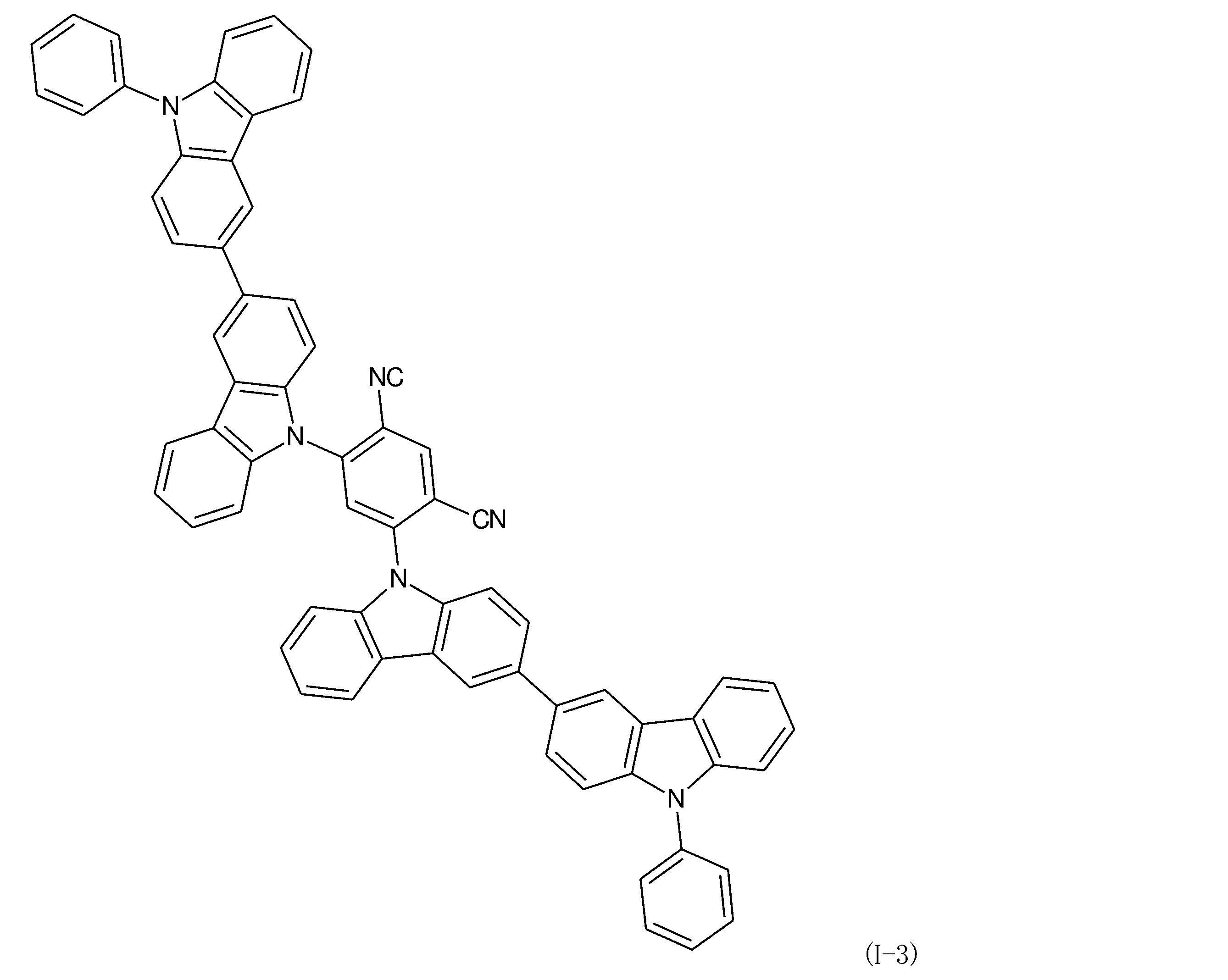


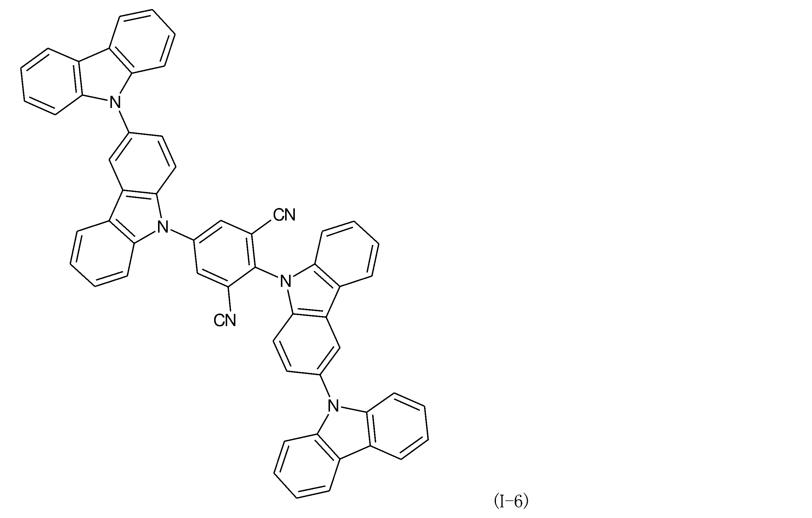

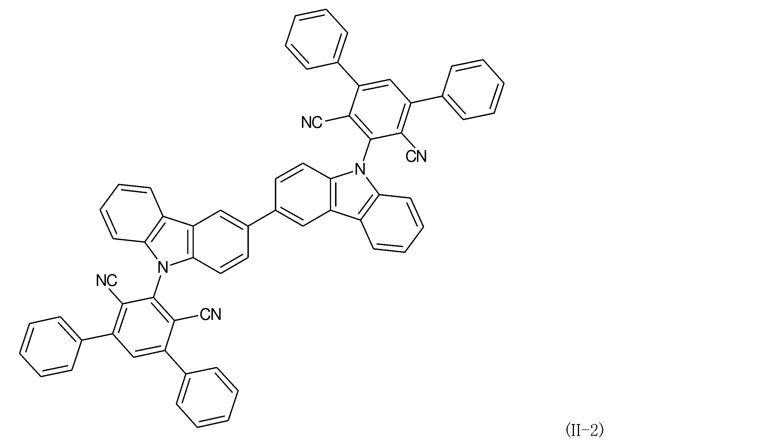

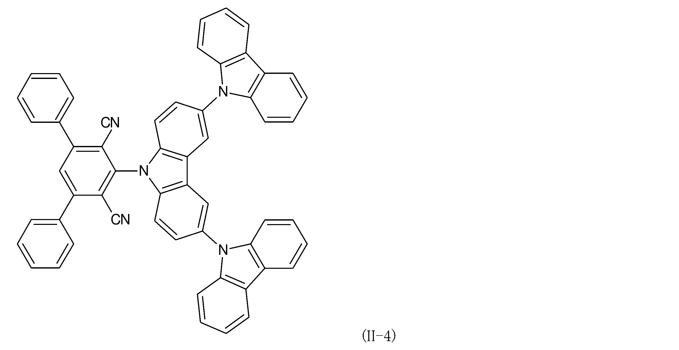

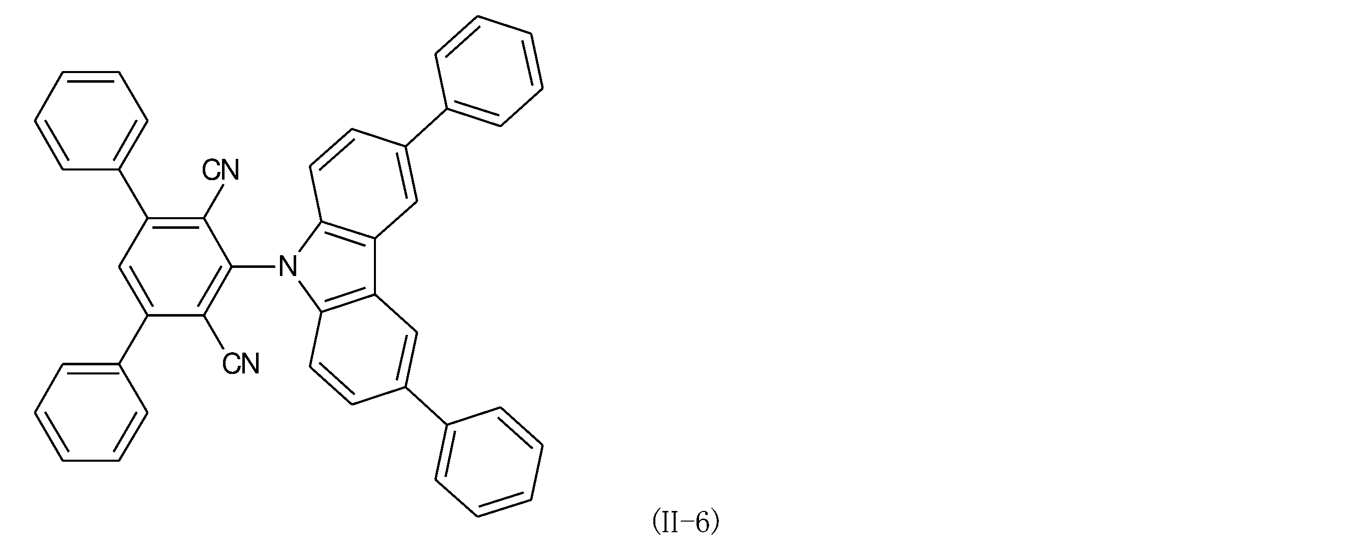
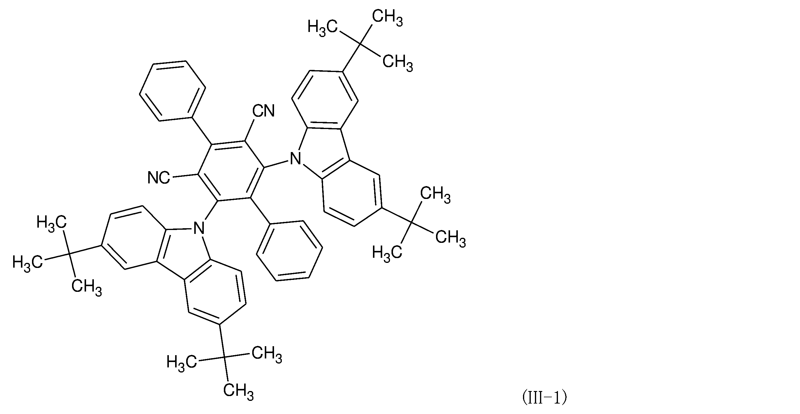

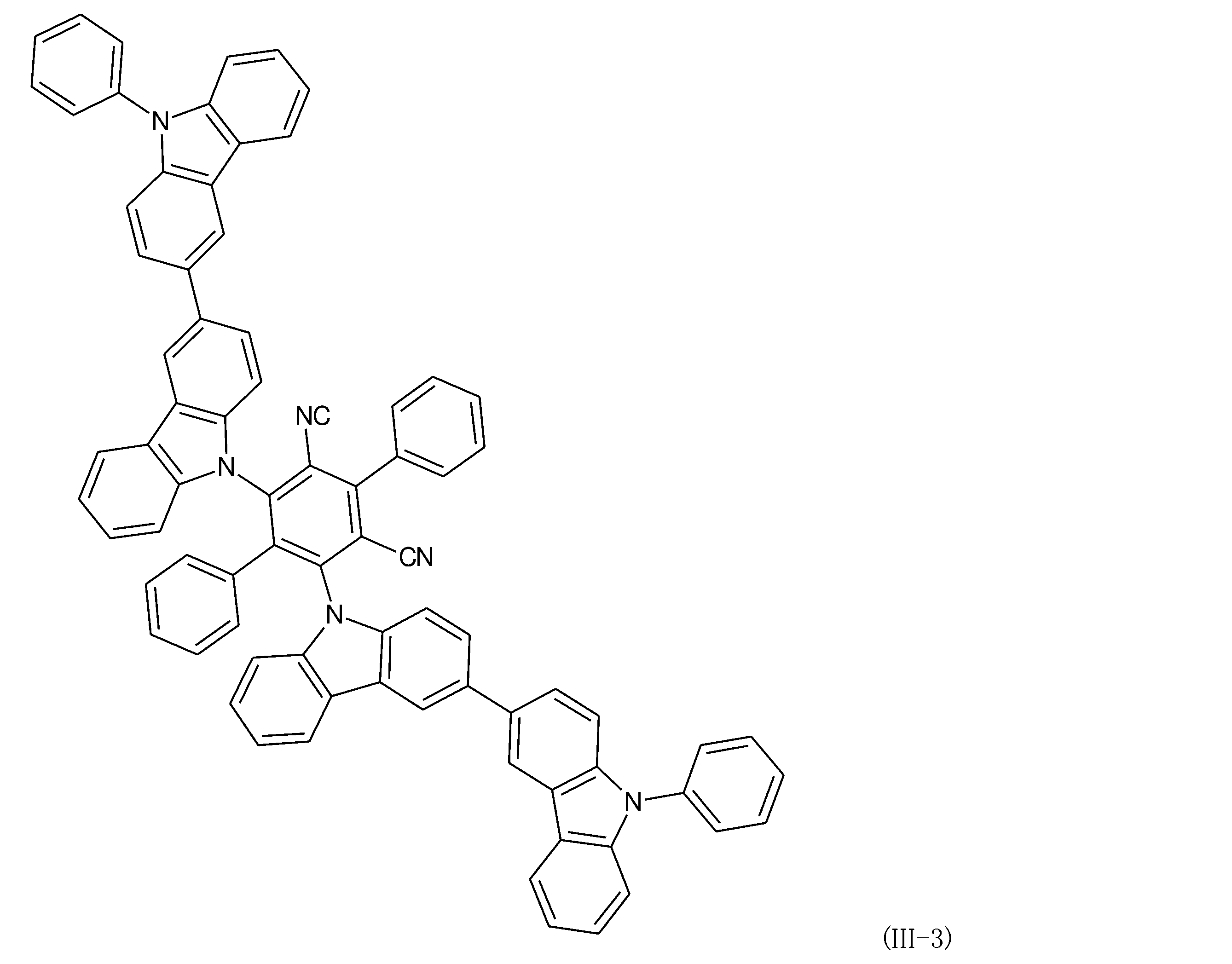
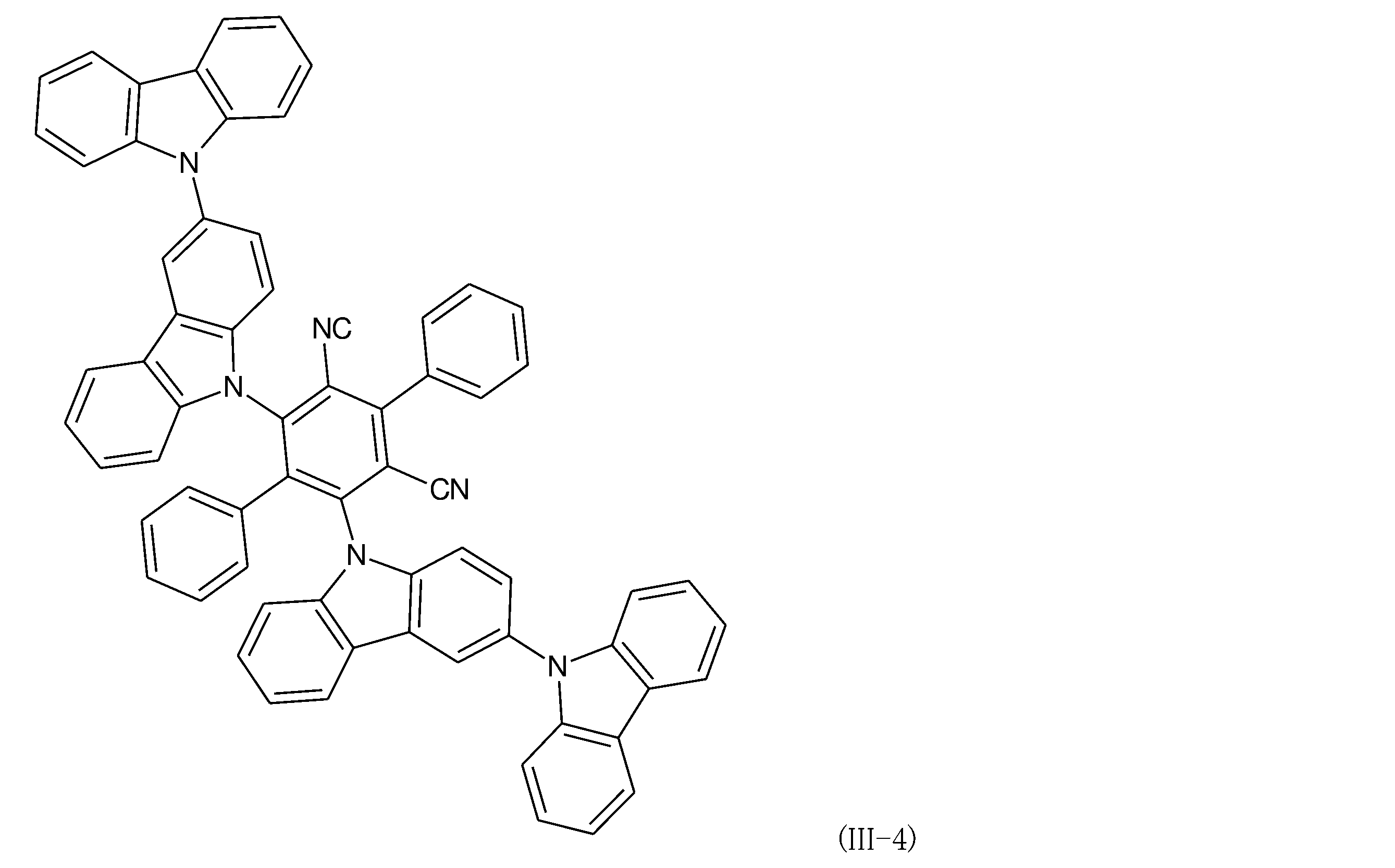

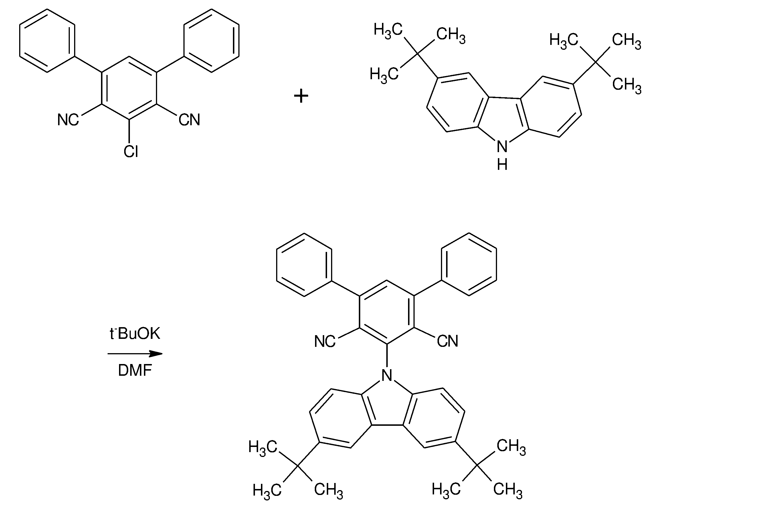
(例1)2,5-ビス(3,6-ジ-tert-ブチル-9H-カルバゾール-9-イル)イソフタロニトリル(化合物(I-1):BCz-2IN-I)の合成


本発明の有機エレクトロルミネッセンス素子の一実施形態における構造としては、基板上に順次に、陽極、正孔注入層、正孔輸送層、電子阻止層、発光層、正孔阻止層、電子輸送層、陰極からなるもの、また、電子輸送層と陰極の間にさらに電子注入層を有するものを挙げることができる。これらの多層構造においては有機層を何層か省略することが可能であり、例えば基板上に順次に、陽極、正孔輸送層、発光層、電子輸送層、電子注入層、陰極とすることや、陽極、正孔輸送層、発光層、電子輸送層、陰極とすることもできる。本発明の発光材料は、発光層のみならず、正孔注入層、正孔輸送層、電子阻止層、正孔阻止層、電子輸送層、または電子注入層にドープさせてもよい。
必要に応じて設けられる正孔輸送層として、トリアゾール誘導体、オキサジアゾール誘導体、イミダゾール誘導体、カルバゾール誘導体、インドロカルバゾール誘導体、ポリアリールアルカン誘導体、ピラゾリン誘導体、ピラゾロン誘導体、フェニレンジアミン誘導体、アリールアミン誘導体、アミノ置換カルコン誘導体、オキサゾール誘導体、スチリルアントラセン誘導体、フルオレノン誘導体、ヒドラゾン誘導体、スチルベン誘導体、シラザン誘導体、アニリン系共重合体、導電性高分子オリゴマーなどを挙げることができる。より具体的に、m-カルバゾリルフェニル基を含有する化合物、N,N’-ジフェニル-N,N’-ジ(m-トリル)-ベンジジン(以後、TPDと略称する)、N,N’-ジフェニル-N,N’-ジ(α-ナフチル)-ベンジジン(以後、NPDと略称する)、N,N,N’,N’-テトラビフェニリルベンジジンなどのベンジジン誘導体、1,1-ビス[(ジ-4-トリルアミノ)フェニル]シクロヘキサン(以後、TAPCと略称する)、種々のトリフェニルアミン3量体および4量体やカルバゾール誘導体などを挙げることができる。これらは、1種単独でまたは2種以上を組み合わせて用いることができる。正孔輸送層は、単層構造の膜であってもよいし、積層構造の膜であってもよい。また、正孔の注入・輸送層として、ポリ(3,4-エチレンジオキシチオフェン)(以後、PEDOTと略称する)/ポリ(スチレンスルフォネート)(以後、PSSと略称する)などの塗布型の高分子材料を用いることができる。これらの材料は蒸着法の他、スピンコート法やインクジェット法などの公知の方法によって薄膜形成を行うことができる。





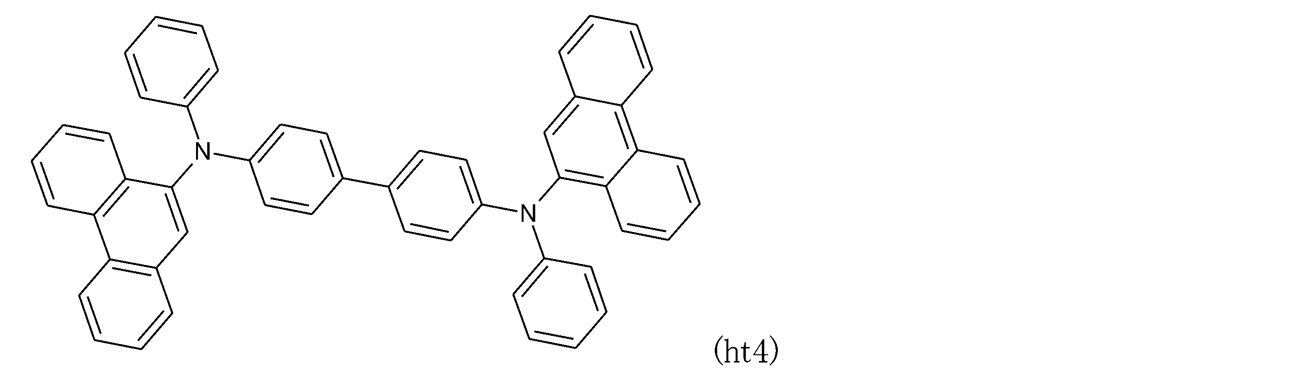
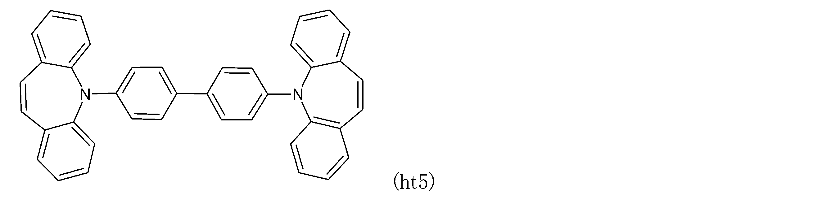
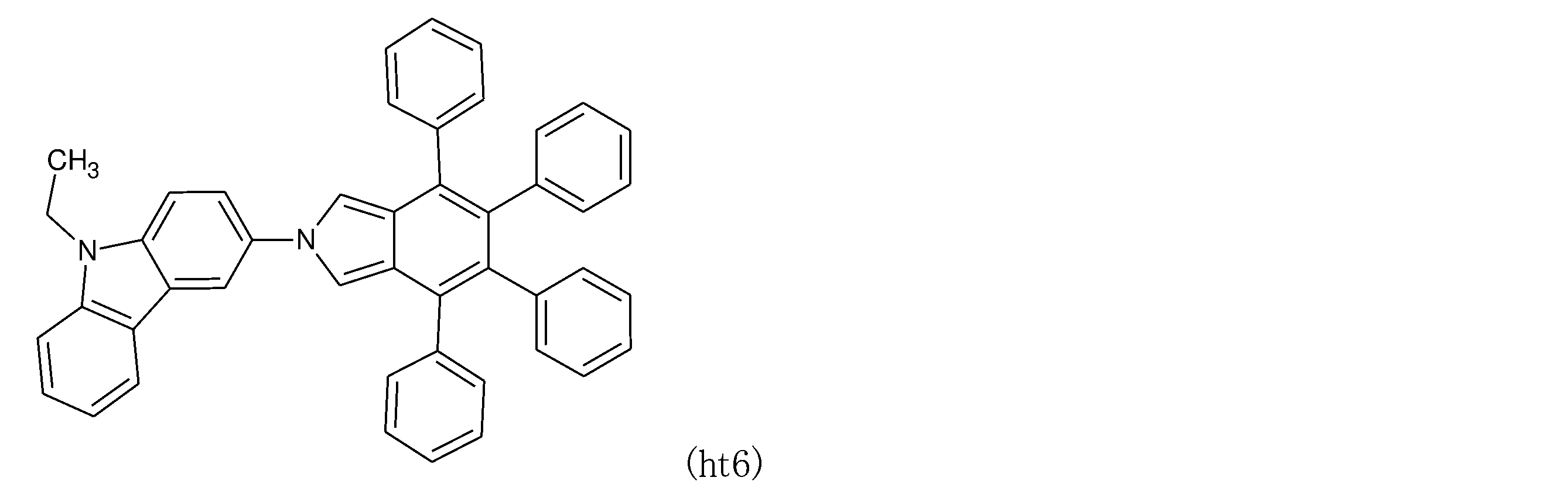
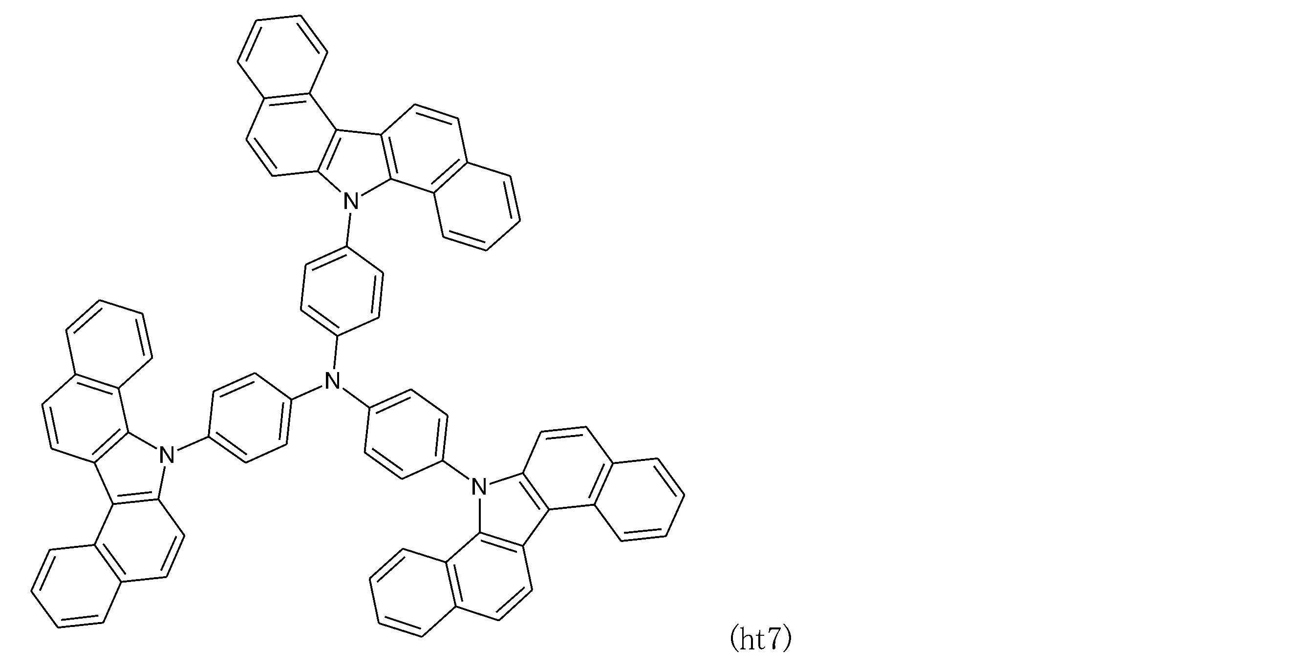

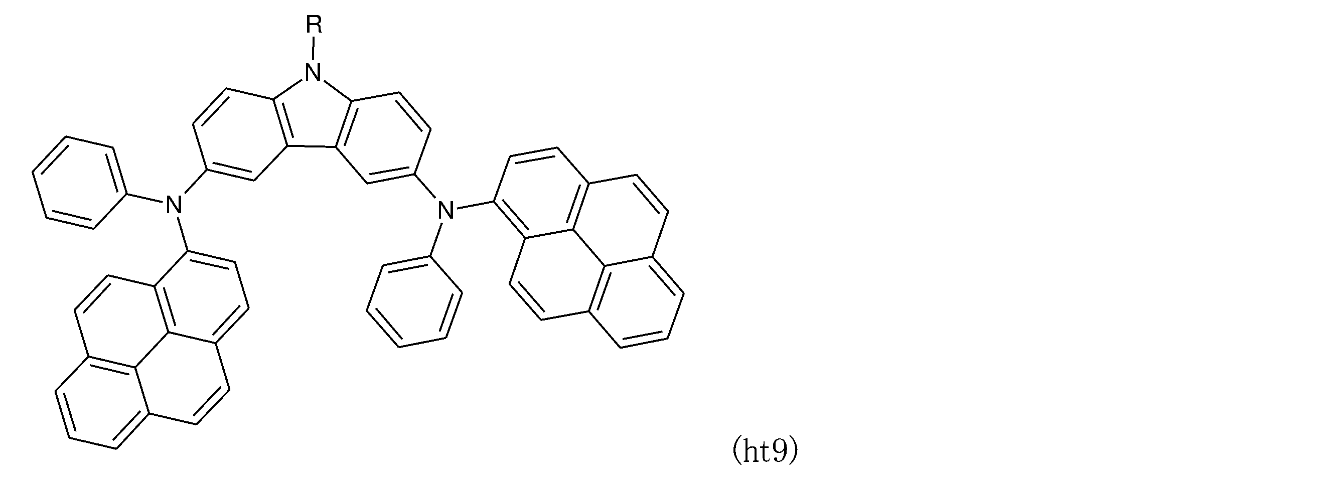
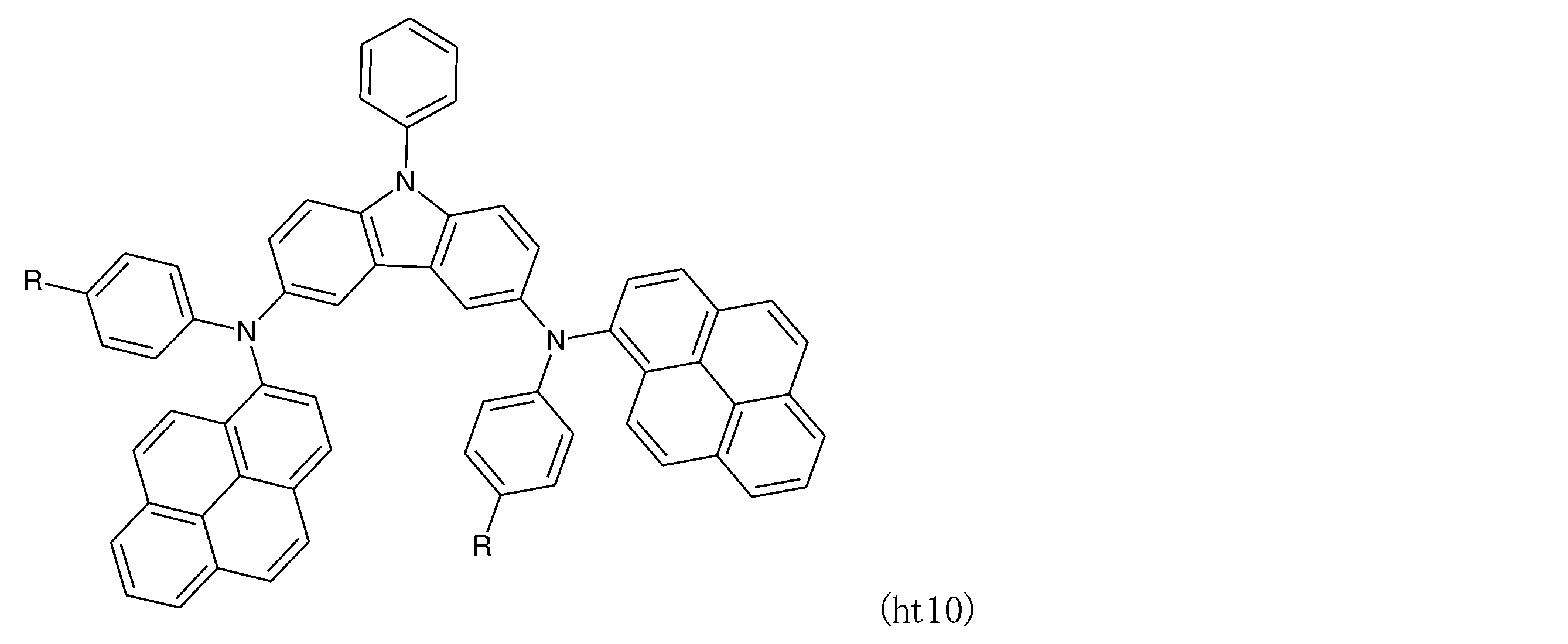
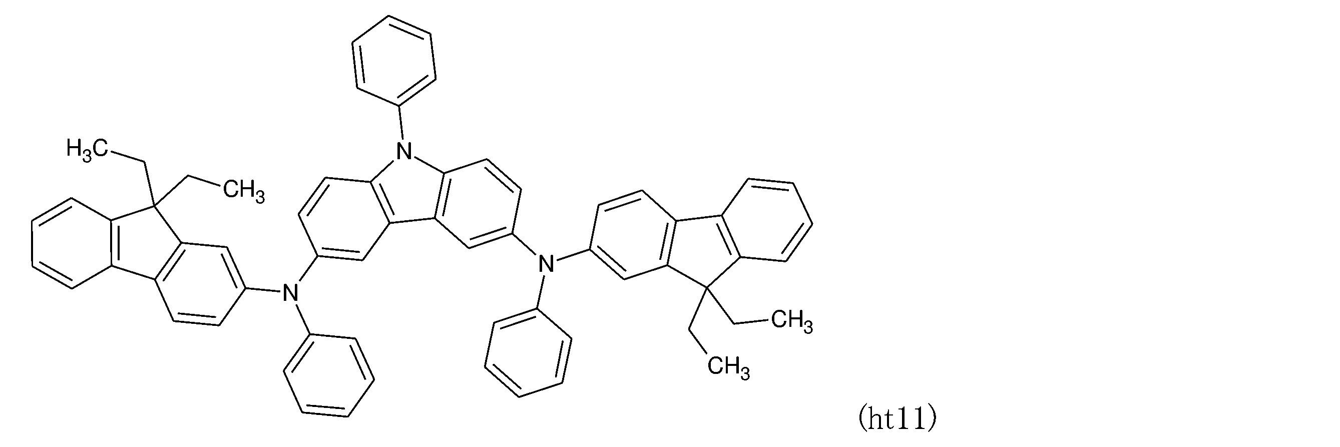
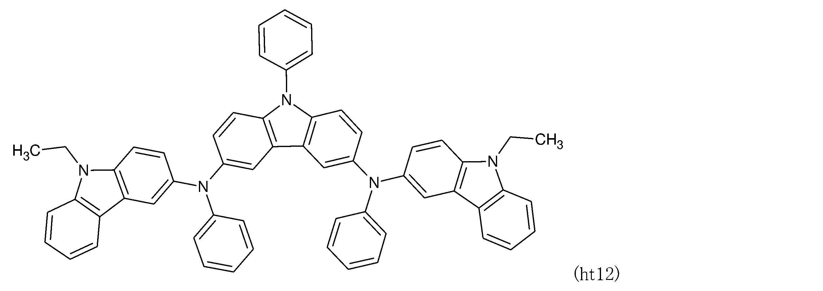

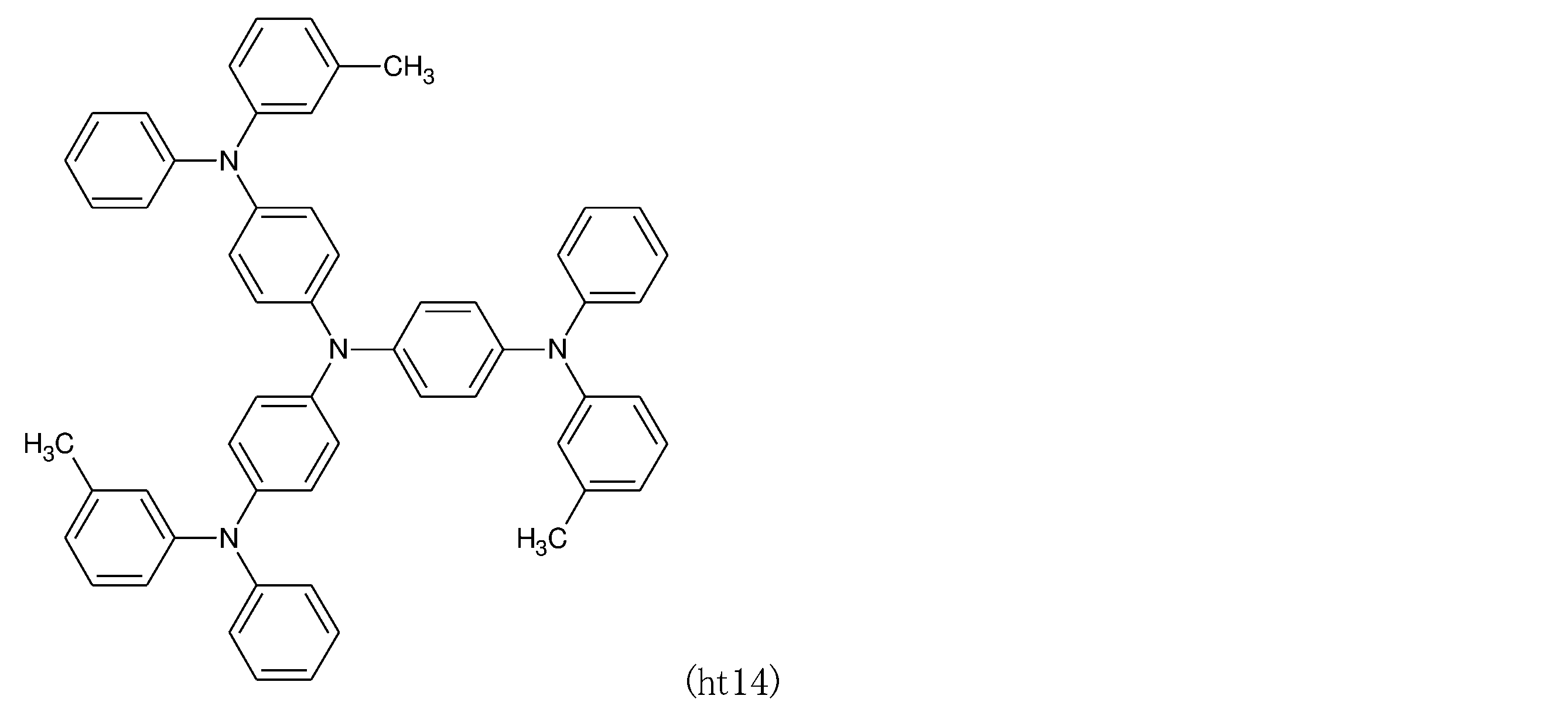
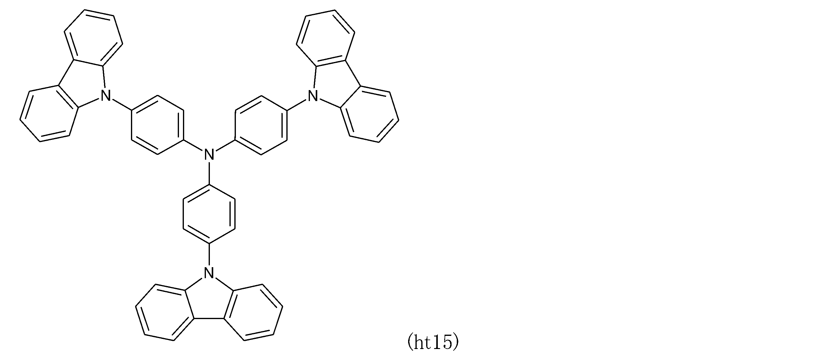
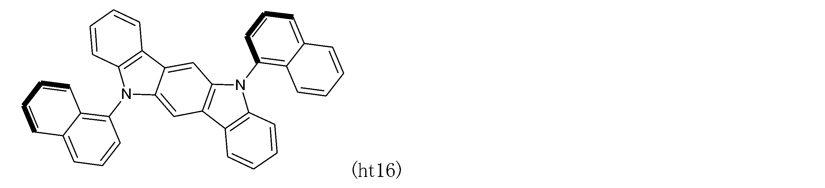
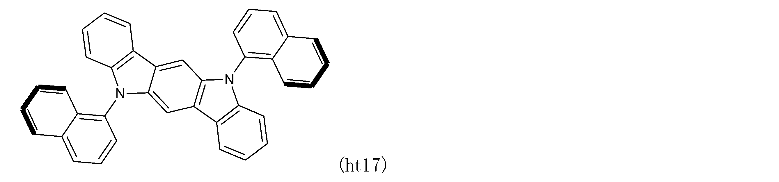
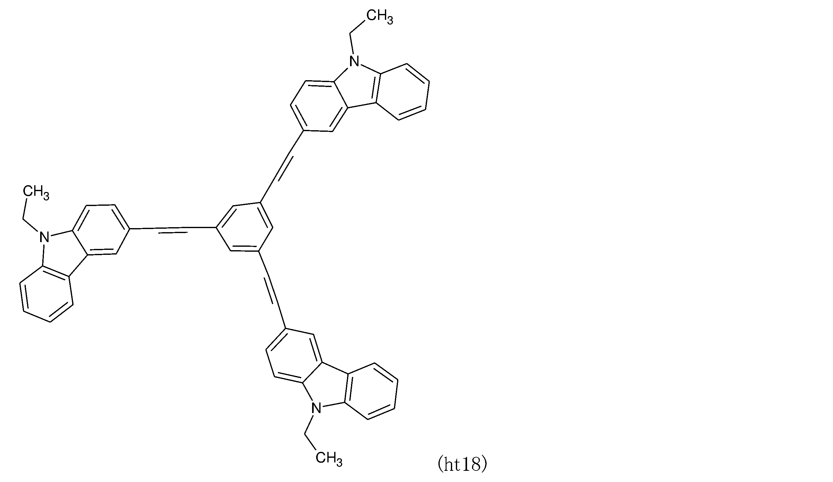
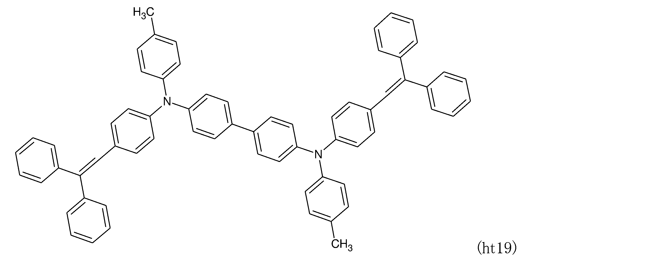


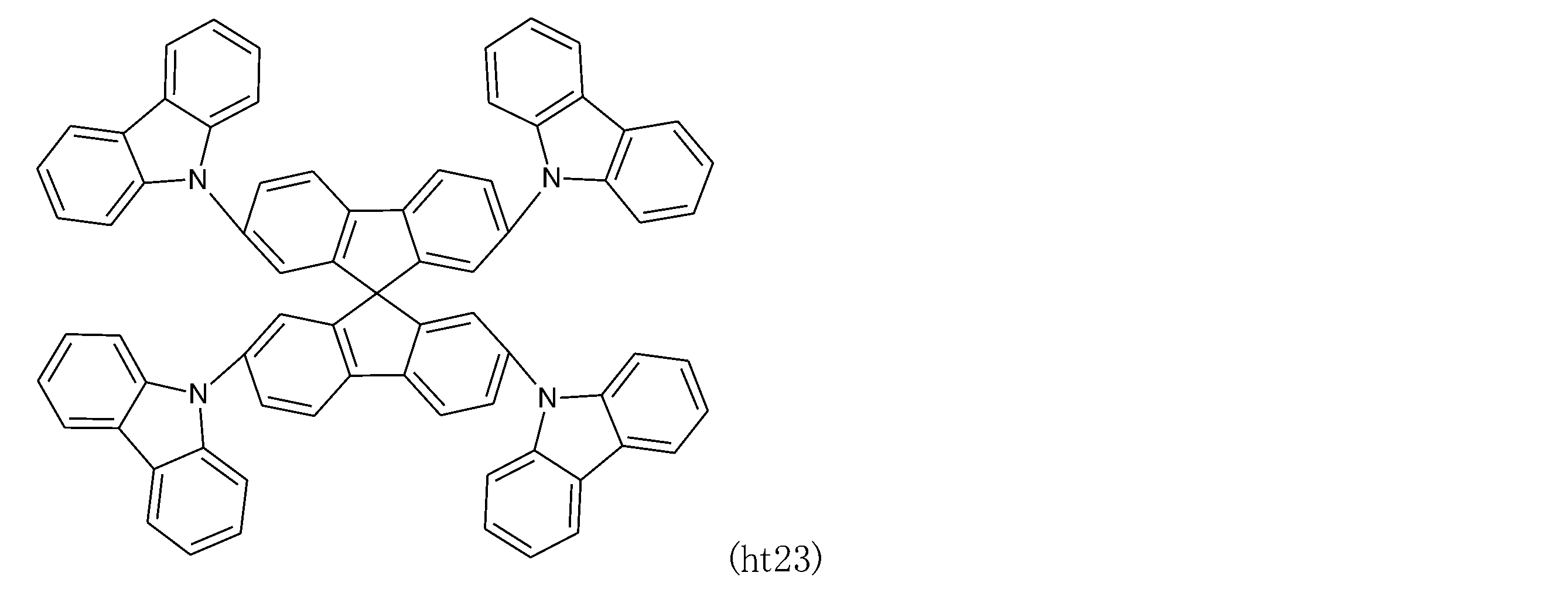




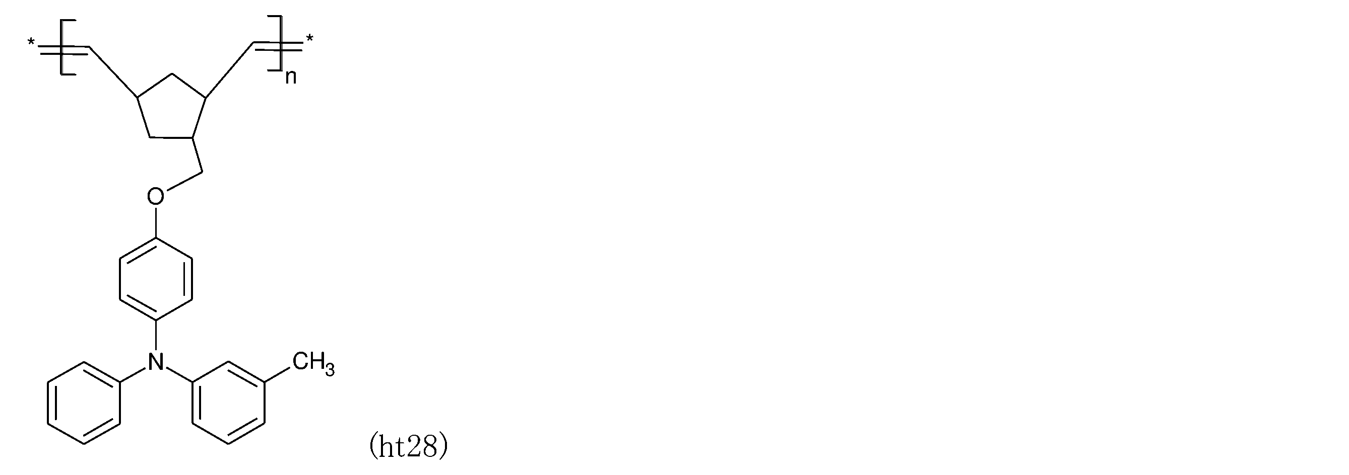

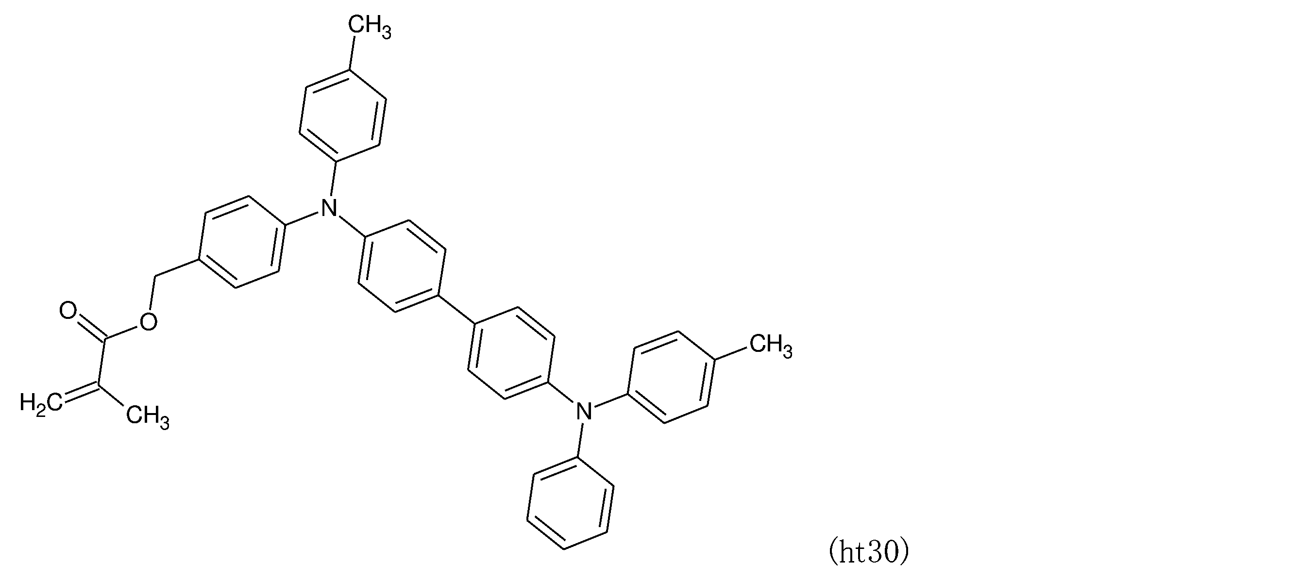
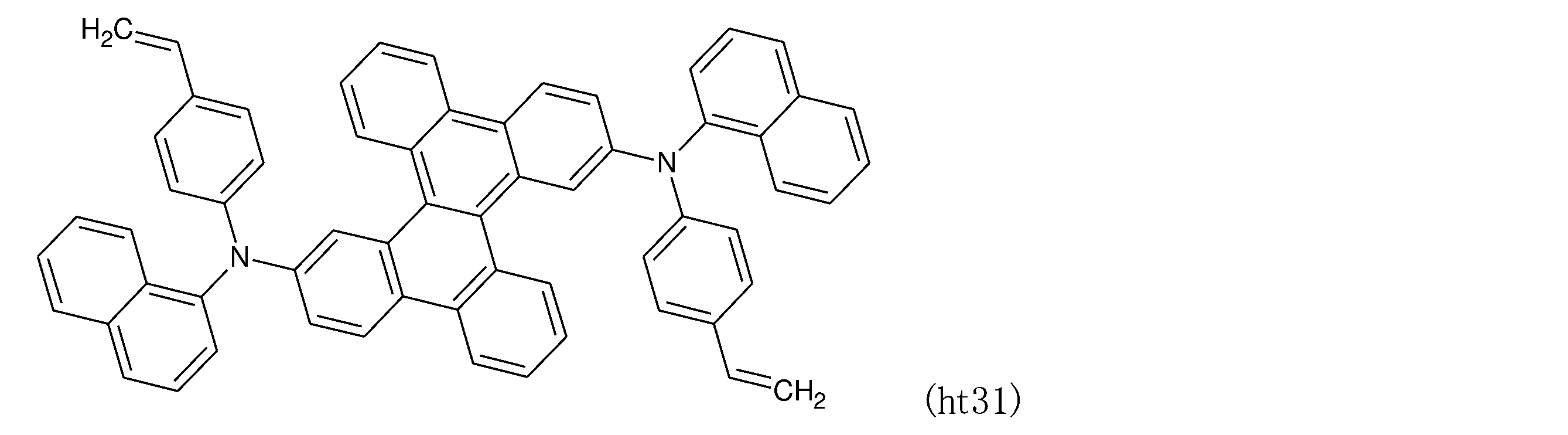

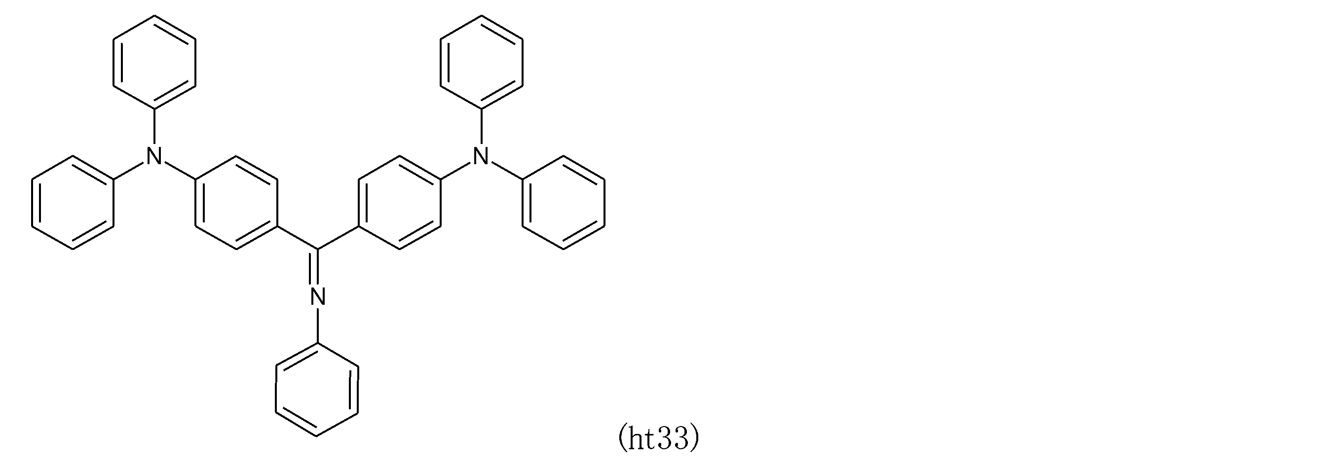


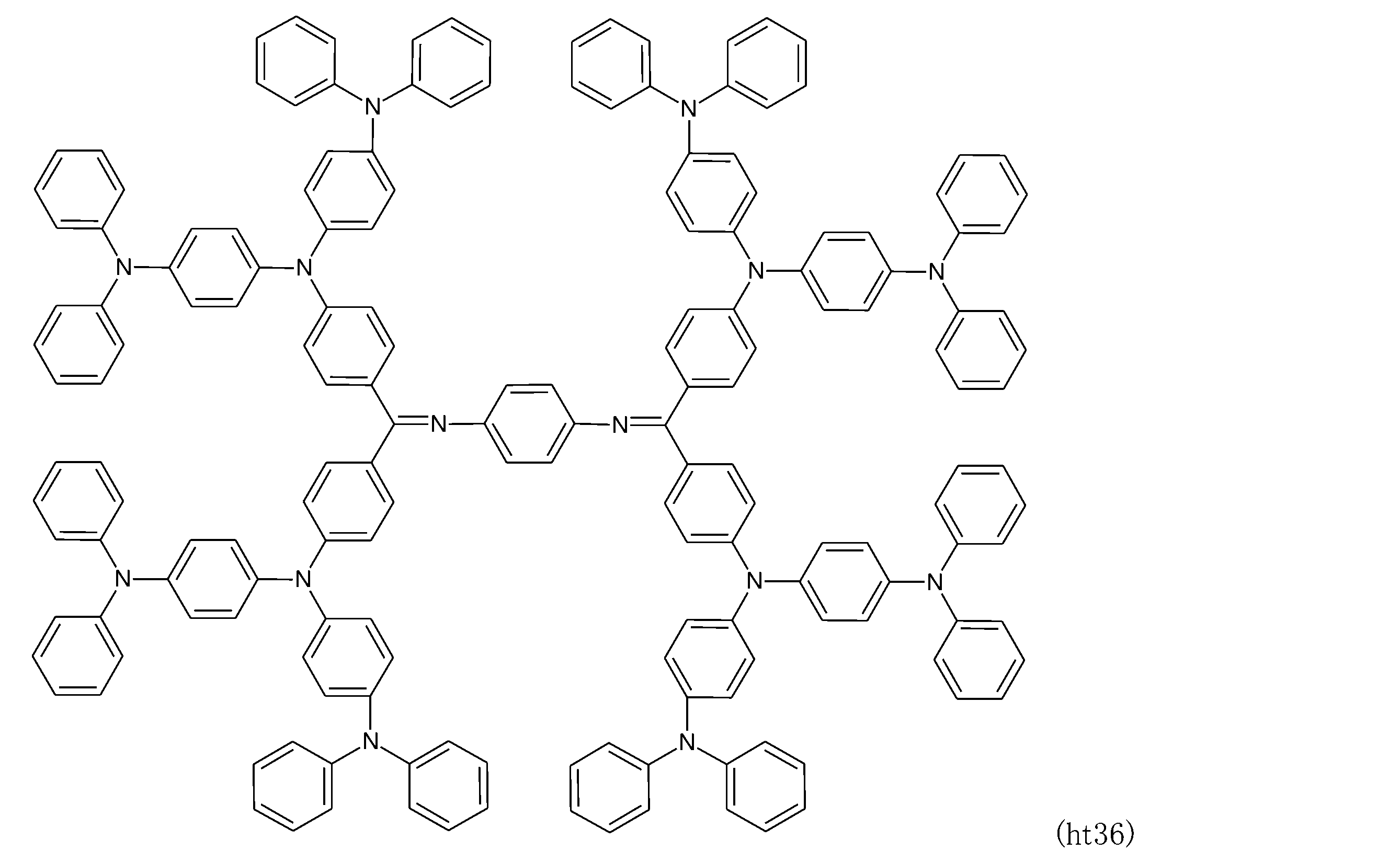

ホスト材料を用いた場合、発光層に含有させることができる本発明の発光材料の量は、下限が、好ましくは0.1質量%、より好ましくは1質量%であり、上限が、好ましくは50質量%、より好ましくは20質量%、さらに好ましくは10質量%である。




































本発明の発光材料を用いて、有機フォトルミネッセンス素子および有機エレクトロルミネッセンス素子を作製し、発光特性を評価した。
発光特性の評価は、ソースメータ(ケースレー社製:2400シリーズ)、分光放射輝度計(コニカミノルタ社製:CS-2000)、分光蛍光光度計(日本分光社製:FP-8600)、および100mmΦ積分球(日本分光社製:ILF-835)を用いて行った。
2,5-ビス(3,6-ジ-tert-ブチル-9H-カルバゾール-9-イル)イソフタロニトリル(BCz-2IN-I)の合成
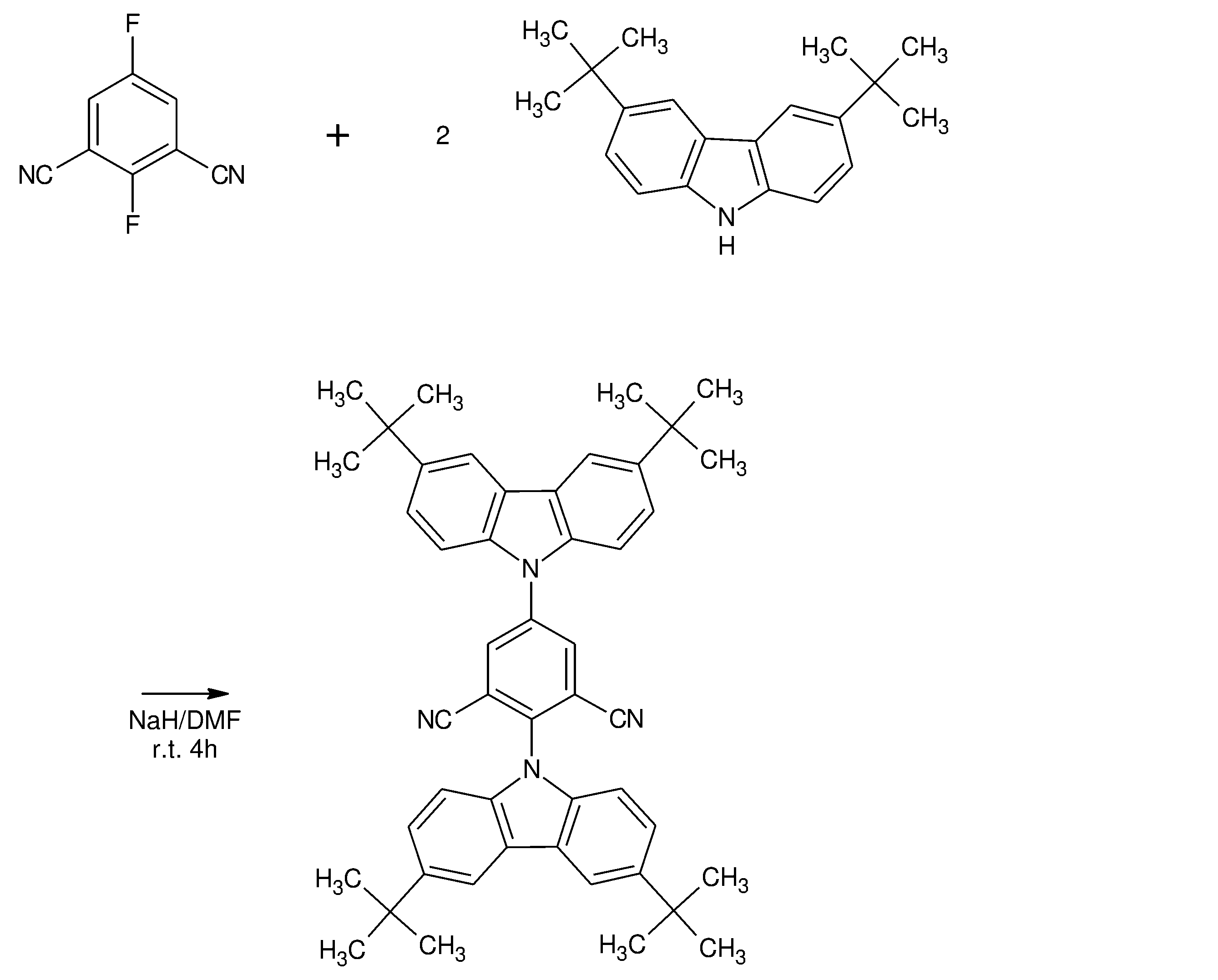
1H-NMR (400 MHz, CDCl3, δ): 8.36 (s, 2H), 8.18 (t, 4H), 7.58 (dd, 2H), 7.54 (dd, 2H), 7.51 (d, 2H), 7.15 (d, 2H), 1.50 (s, 18H), 1.49 (s, 18H)
2,4-ビス(3,6-ジ-tert-ブチル-9H-カルバゾール-9-イル)イソフタロニトリル(略号:BCz-2IN-II)の合成
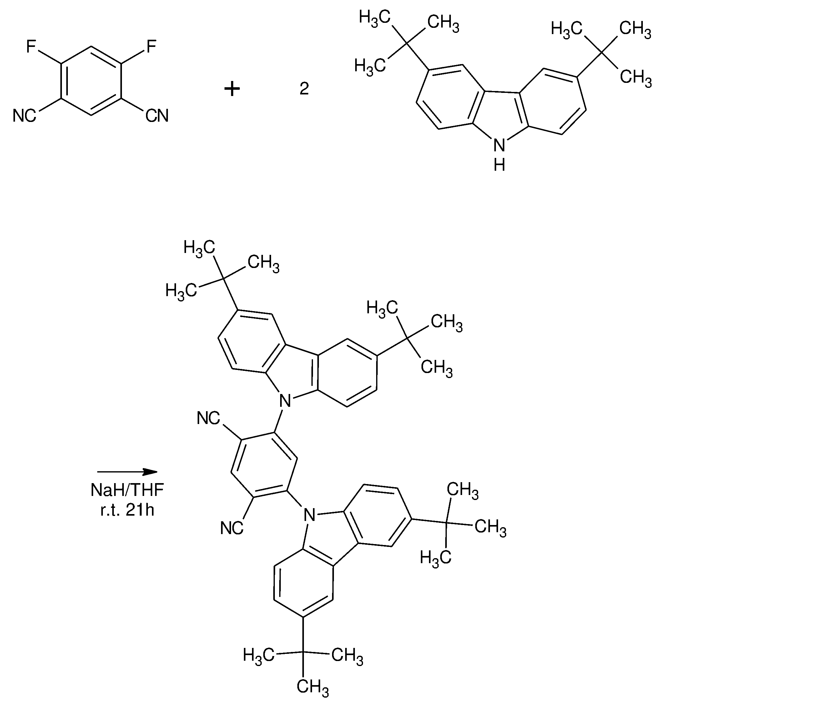
1H-NMR (400MHz, CDCl3, δ): 8.45 (s, 1H), 8.11 (d, J = 1.2 Hz, 4H), 7.89 (s, 1H), 7.50 (dd, J = 8.8 Hz, 1.6 Hz, 4H), 7.27 (d, J = 8.4 Hz, 4H), 1.45 (s, 36H)
2-(3,6-ジ-tert-ブチル-9H-カルバゾール-9-イル)-4,6-ジフェニル-イソフタロニトリル(BCz-2PIN)の合成

1H-NMR (400 MHz, CDCl3, δ): 8.18 (t, J = 0.9 Hz, 2H), 7.83 (s, 1H), 7.71-7.75 (m, 4H), 7.52-7.60 (m, 8H), 7.18 (d, J = 8.5 Hz, 2H), 1.46 (s, 18H).
13C NMR (125 MHz, CDCl3, δ): 151.12, 146.17, 144.246, 138.75, 136.19, 130.88, 130.2, 135.66, 134.14, 125.09, 124.59, 124.20, 123.37, 122.15, 117.63, 116.21, 115.51, 115.07, 112.35, 109.89, 109.10, 109.04, 35.09, 34.70, 34.42, 32.17, 31.88.
窒素雰囲気のグローブボックス中で、BCz-2PIN、BCz-2IN-I、およびBCz-2IN-IIのトルエン溶液(濃度10-5M)をそれぞれ調製し、発光材料とした。これらの発光材料についてPLスペクトルを測定した。その結果を図1に示す。
膜厚50nmのインジウム・スズ酸化物(ITO)からなる陽極が形成されたガラス基板上に10nm厚のHAT-CN(ジピラジノ[2,3-F:2',3'-H]キノキサリン-2,3,6,7,10,11-ヘキサカルボニトリル)層、40nm厚のTAPC(ジ-[4-(N,N-ジトリル-アミノ)-フェニル]シクロヘキサン)層、10nm厚のCCP(1,4-ビス(カルバゾリル)ベンゼン)層、10nm厚のmCP(1,3-ビス(N-カルバゾリル)ベンゼン)層、20nm厚の発光層、10nm厚のPPF(2,8-ビス(ジフェニルフォスフィンオキシド)ジベンゾフラン)層および40nm厚のB3PyPBM(1,3-ビス(3,5-ジピリド-3-イルフェニル)ベンゼン)層をこの順で真空蒸着法(5.0×10⁻⁴Pa以下)によって積層させた。次いで、1nm厚の8-ヒドロキシキノリトリチウム膜、および100nm厚のアルミニウム膜をこの順で真空蒸着法にて積層させることにより陰極を形成させて、有機エレクトロルミネッセンス素子を得た。
発光層のドープ材料としてBCz-2PIN、BCz-IN-I、およびBCz-IN-IIをそれぞれ用いた。ドーブ材料濃度を20重量%(in PPF)に設定した。
有機エレクトロルミネッセンス素子の特性を測定した。図2に電圧-電流密度-発光強度特性を示す。図2中、黒印は電流密度を示し、白抜き印は発光強度を示す。図3に電流密度-外部量子効率特性を示す。その他の結果を表1に示す。
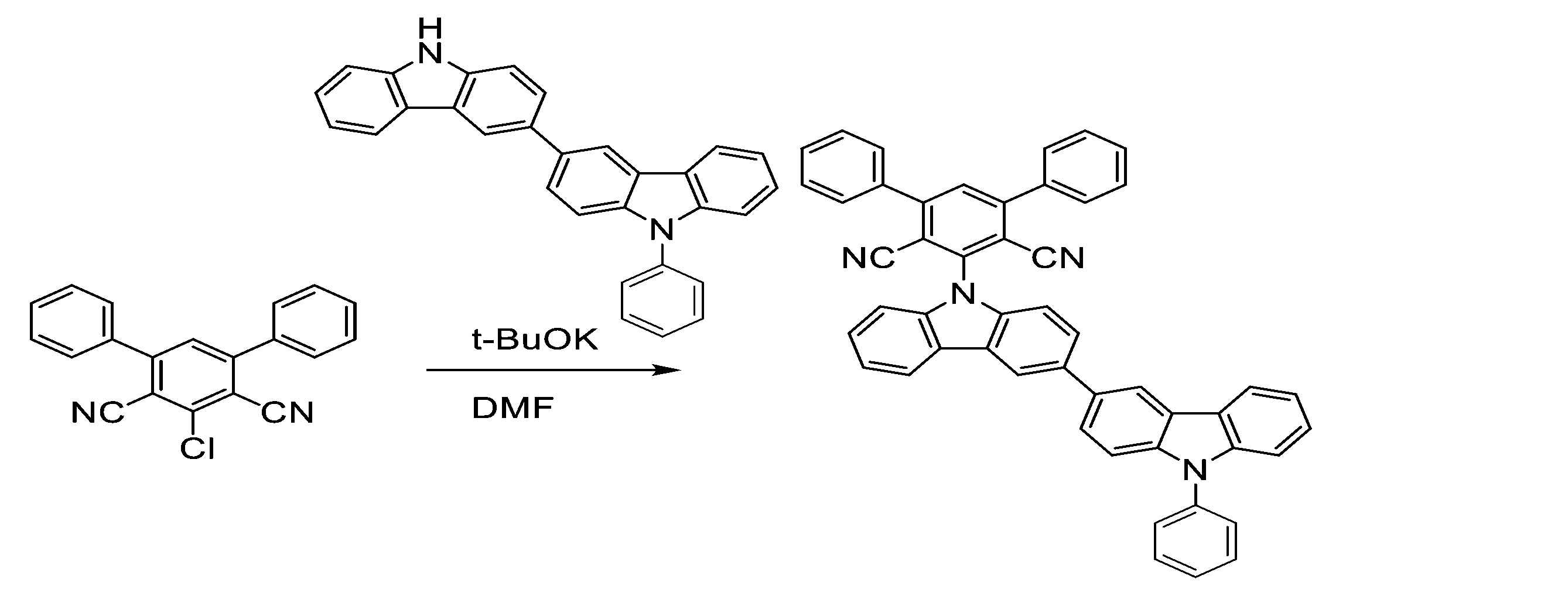
2-(3-(9-フェニル-9H-カルバゾール-3-イル)-9H-カルバゾール-9-イル)-4,6-ジフェニル-イソフタロニトリル(Ph-BiCz-PIN)の合成
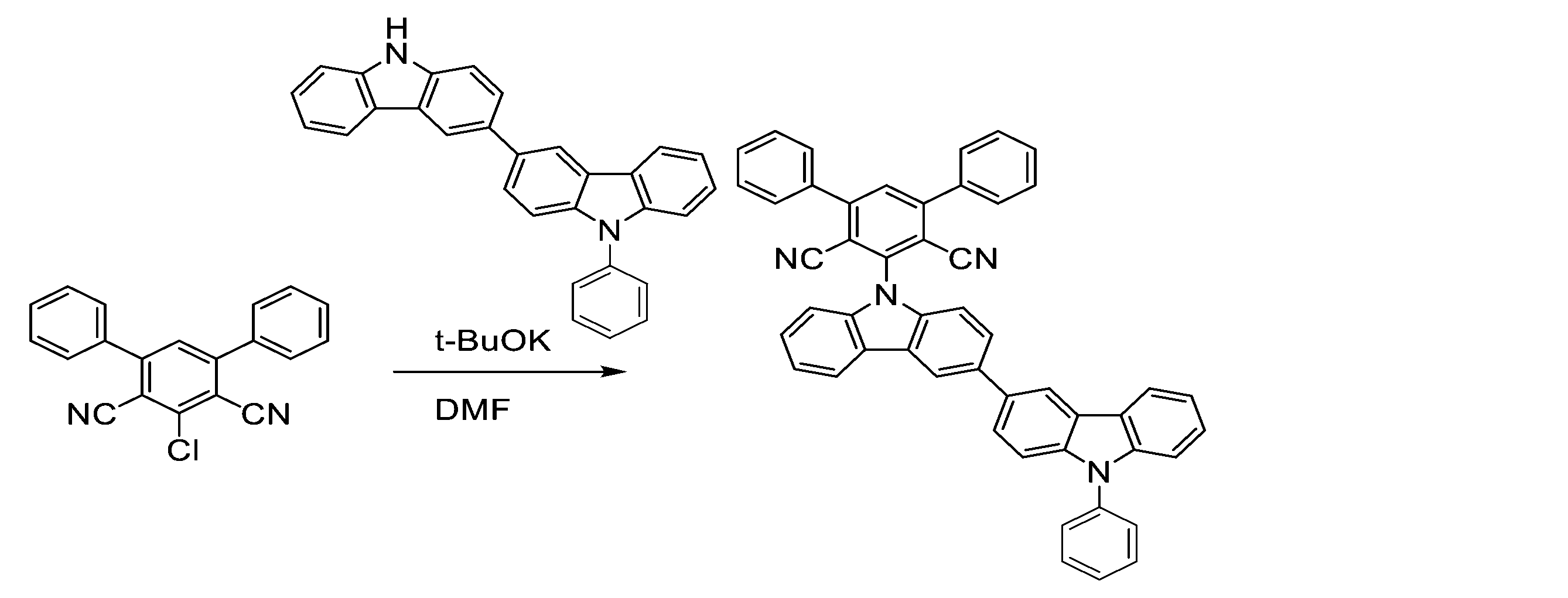
1H-NMR (400 MHz, CDCl3, δ): 8.47 (d, J = 1.8 Hz, 2H), 8.26 (dd, J = 8.5, 7.8 Hz, 2H), 7.87 (s, 1H), 7.84 (dd, J = 8.4, 1.9 Hz, 1H), 7.78 (dd, J = 8.5, 1.8 Hz, 1H), 7.75-7.73 (m, 4H), 7.65-7.62 (m, 4H), 7.60-7.31 (m, 15H)
2-(3-(9-(4,6-ジフェニル-イソフタロニトリル-2-イル)-9H-カルバゾール-3-イル)-9H-カルバゾール-9-イル)-4,6-ジフェニル-イソフタロニトリル(BiCz-2PIN)の合成
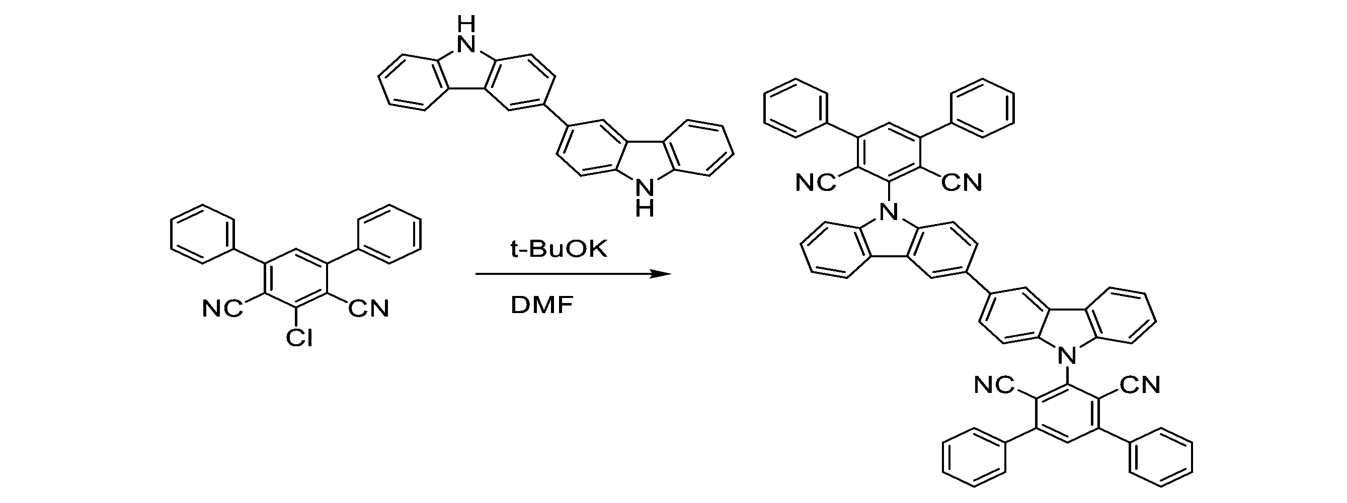
1H-NMR (400MHz, CDCl3, δ): 8.47 (d, J = 1.3 Hz, 2H), 8.26 (d, J = 7.8 Hz, 2H), 7.87 (s, 2H), 7.83 (dd, J = 8.4, 1.9 Hz, 2H), 7.75-7.72 (m, 8H), 7.61-7.50 (m, 14H), 7.43-7.35 (m, 4H), 7.28 (d, J = 8.0 Hz, 2H)
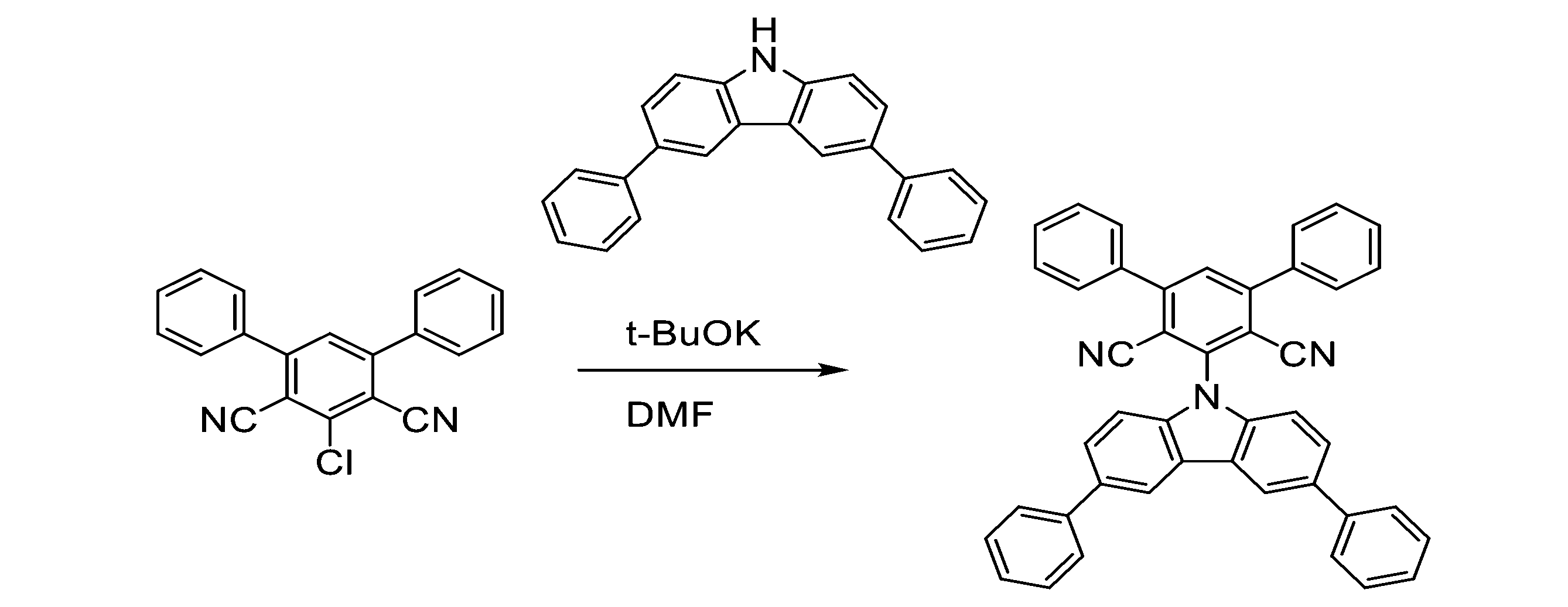
2-(3,6-ジ-フェニル-9H-カルバゾール-9-イル)-4,6-ジフェニル-イソフタロニトリル(PCz-PIN)の合成
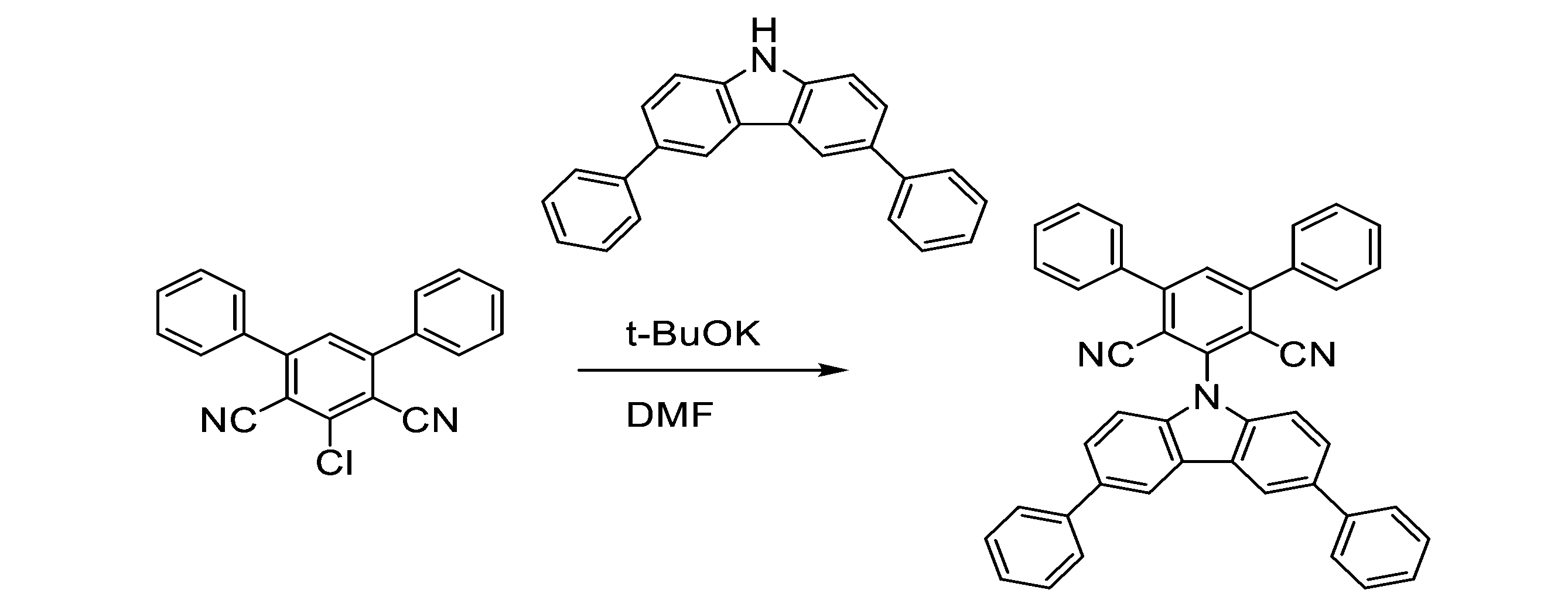
1H-NMR (400 MHz, CDCl3, δ): 8.41 (d, J = 1.3 Hz, 2H), 7.88 (s, 1H), 7.75-7.71 (m, 10H), 7.61-7.47 (m, 10H), 7.39-7.31 (m, 4H)
窒素雰囲気のグローブボックス中で、Ph-BiCz-PIN、BiCz-2PIN、およびPCz-PINのトルエン溶液(濃度10-5M)をそれぞれ調製し、発光材料とした。これらの発光材料についてPLスペクトルを測定した。その結果を図4に示す。
膜厚50nmのインジウム・スズ酸化物(ITO)からなる陽極が形成されたガラス基板上に10nm厚のHAT-CN層、40nm厚のTAPC層、10nm厚のCCP層、10nm厚のmCP層、20nm厚の発光層、10nm厚のPPF層および40nm厚のB3PyPBM層をこの順で真空蒸着法(5.0×10⁻⁴Pa以下)によって積層させた。次いで、1nm厚の8-ヒドロキシキノリトリチウム膜、および100nm厚のアルミニウム膜をこの順で真空蒸着法にて積層させることにより陰極を形成させて、有機エレクトロルミネッセンス素子を得た。
発光層のドープ材料としてPh-BiCz-PIN、BiCz-2PIN、およびPCz-PINをそれぞれ用いた。ドーブ材料濃度を20重量%(in PPF)に設定した。
有機エレクトロルミネッセンス素子の特性を測定した。図5に電圧-電流密度-発光強度特性を示す。図5中、黒印は電流密度を示し、白抜き印は発光強度を示す。図6に電流密度-外部量子効率特性を示す。その他の結果を表2に示す。
Claims (3)
- 式(I)、式(II)または式(III)で表される化合物。

R1、R2、R3およびR4は、それぞれ独立して、水素原子、アルキル基、またはヘテロアリール基であり、且つR1、R2、R3およびR4が同時に水素原子であることはない。)
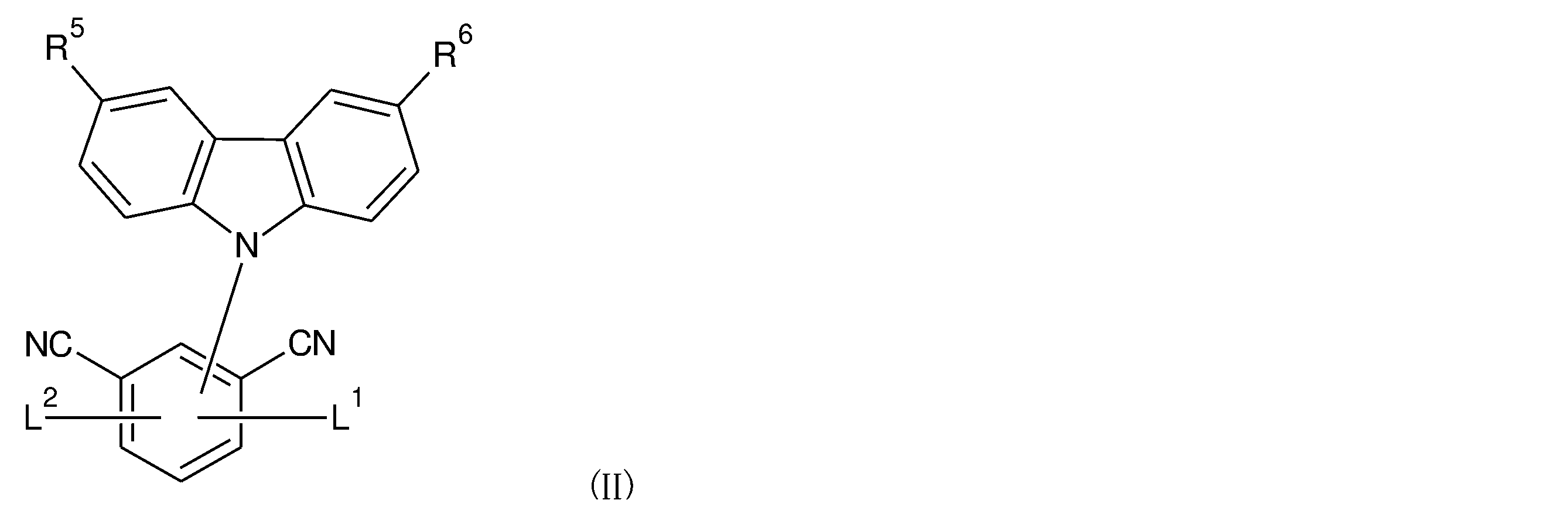
R5およびR6は、それぞれ独立して、水素原子、アルキル基、アリール基、またはヘテロアリール基であり、R5およびR6が同時に水素原子であることはなく、
L1およびL2は、それぞれ独立して、アリール基である。)
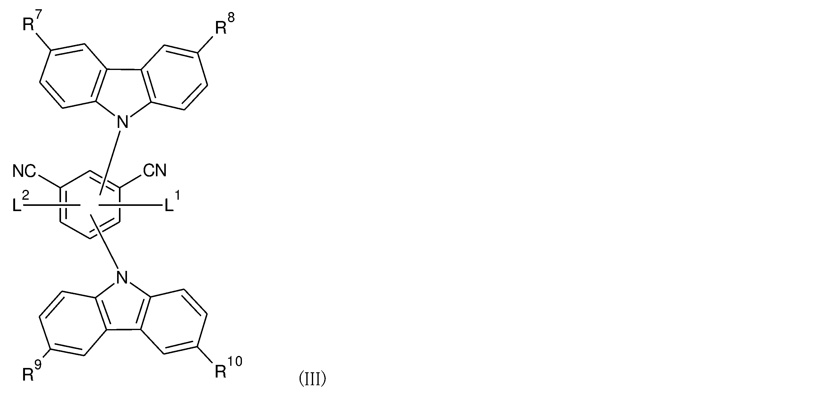
R7、R8、R9およびR10は、それぞれ独立して、水素原子、アリール基、またはヘテロアリール基であり、R7、R8、R9およびR10が同時に水素原子であることはなく、且つ
L1、およびL2は、それぞれ独立して、アリール基である。) - 請求項1に記載の化合物から選ばれる少なくともひとつを含む発光材料。
- 請求項2に記載の発光材料を含有する発光素子。
Priority Applications (5)
| Application Number | Priority Date | Filing Date | Title |
|---|---|---|---|
| US17/616,127 US12497363B2 (en) | 2019-06-14 | 2020-06-08 | Isophthalonitrile compound, luminescent material and luminescent element using the same |
| KR1020217038904A KR102671951B1 (ko) | 2019-06-14 | 2020-06-08 | 이소프탈로니트릴 화합물, 발광 재료 및 그것을 사용한 발광 소자 |
| EP20823145.6A EP3985081B1 (en) | 2019-06-14 | 2020-06-08 | Isophthalonitrile compounds, luminescent material, and luminescent element including same |
| JP2021526078A JP7386486B2 (ja) | 2019-06-14 | 2020-06-08 | イソフタロニトリル化合物、発光材料およびそれを用いた発光素子 |
| CN202080041797.3A CN113939501B (zh) | 2019-06-14 | 2020-06-08 | 间苯二腈化合物、发光材料及使用其的发光元件 |
Applications Claiming Priority (2)
| Application Number | Priority Date | Filing Date | Title |
|---|---|---|---|
| JP2019-111304 | 2019-06-14 | ||
| JP2019111304 | 2019-06-14 |
Publications (1)
| Publication Number | Publication Date |
|---|---|
| WO2020250851A1 true WO2020250851A1 (ja) | 2020-12-17 |
Family
ID=73781216
Family Applications (1)
| Application Number | Title | Priority Date | Filing Date |
|---|---|---|---|
| PCT/JP2020/022547 Ceased WO2020250851A1 (ja) | 2019-06-14 | 2020-06-08 | イソフタロニトリル化合物、発光材料およびそれを用いた発光素子 |
Country Status (7)
| Country | Link |
|---|---|
| US (1) | US12497363B2 (ja) |
| EP (1) | EP3985081B1 (ja) |
| JP (1) | JP7386486B2 (ja) |
| KR (1) | KR102671951B1 (ja) |
| CN (1) | CN113939501B (ja) |
| TW (1) | TWI741639B (ja) |
| WO (1) | WO2020250851A1 (ja) |
Families Citing this family (1)
| Publication number | Priority date | Publication date | Assignee | Title |
|---|---|---|---|---|
| KR102533313B1 (ko) * | 2018-09-05 | 2023-05-16 | 고쿠리쓰다이가쿠호진 규슈다이가쿠 | 벤조니트릴 유도체, 발광 재료 및 그것을 사용한 발광 소자 |
Citations (10)
| Publication number | Priority date | Publication date | Assignee | Title |
|---|---|---|---|---|
| WO2013154064A1 (ja) | 2012-04-09 | 2013-10-17 | 国立大学法人九州大学 | 有機発光素子ならびにそれに用いる発光材料および化合物 |
| JP2016516085A (ja) * | 2013-03-22 | 2016-06-02 | メルク パテント ゲーエムベーハー | 電子素子のための材料 |
| CN107652225A (zh) * | 2017-09-29 | 2018-02-02 | 江苏三月光电科技有限公司 | 一种以氰基苯为核心的化合物及其在oled器件上的应用 |
| WO2018237389A1 (en) * | 2017-06-23 | 2018-12-27 | Kyulux Inc. | Composition of matter for use in organic light-emitting diodes |
| WO2019004254A1 (ja) | 2017-06-27 | 2019-01-03 | 株式会社Kyulux | 発光材料、化合物、遅延蛍光体および発光素子 |
| JP2019006988A (ja) * | 2017-06-27 | 2019-01-17 | 株式会社Kyulux | 発光材料、化合物、遅延蛍光体および発光素子 |
| KR20190049525A (ko) * | 2017-10-30 | 2019-05-09 | 주식회사 엘지화학 | 헤테로고리 화합물 및 이를 포함하는 유기 발광 소자 |
| KR20190062250A (ko) * | 2017-11-28 | 2019-06-05 | 주식회사 엘지화학 | 화합물 및 이를 포함하는 유기 발광 소자 |
| JP2019111304A (ja) | 2017-12-25 | 2019-07-11 | 光敏 栢島 | 端部硬化型可撓性帯状体着脱式接続具 |
| WO2019195104A1 (en) * | 2018-04-02 | 2019-10-10 | Kyulux, Inc. | Composition of matter for use in organic light-emitting diodes |
Family Cites Families (6)
| Publication number | Priority date | Publication date | Assignee | Title |
|---|---|---|---|---|
| KR20090089073A (ko) | 2008-02-18 | 2009-08-21 | 삼성모바일디스플레이주식회사 | 실란일아민계 화합물 및 이를 포함한 유기막을 구비한 유기발광 소자 |
| TWI645014B (zh) * | 2013-07-16 | 2018-12-21 | 國立大學法人九州大學 | 化合物、發光材料及有機發光元件 |
| KR101783650B1 (ko) * | 2014-06-24 | 2017-10-23 | 제일모직주식회사 | 화합물, 이를 포함하는 유기광전자소자 및 표시장치 |
| KR101929860B1 (ko) * | 2015-05-15 | 2018-12-17 | 삼성에스디아이 주식회사 | 유기광전자소자 및 표시장치 |
| CN108264478B (zh) | 2016-12-30 | 2020-09-22 | 昆山国显光电有限公司 | 载流子传输材料及载流子传输层及有机发光器件 |
| KR102743332B1 (ko) * | 2018-12-19 | 2024-12-18 | 삼성디스플레이 주식회사 | 유기 발광 소자 및 이를 포함하는 표시 장치 |
-
2020
- 2020-06-08 WO PCT/JP2020/022547 patent/WO2020250851A1/ja not_active Ceased
- 2020-06-08 EP EP20823145.6A patent/EP3985081B1/en active Active
- 2020-06-08 US US17/616,127 patent/US12497363B2/en active Active
- 2020-06-08 JP JP2021526078A patent/JP7386486B2/ja active Active
- 2020-06-08 TW TW109119133A patent/TWI741639B/zh active
- 2020-06-08 CN CN202080041797.3A patent/CN113939501B/zh active Active
- 2020-06-08 KR KR1020217038904A patent/KR102671951B1/ko active Active
Patent Citations (10)
| Publication number | Priority date | Publication date | Assignee | Title |
|---|---|---|---|---|
| WO2013154064A1 (ja) | 2012-04-09 | 2013-10-17 | 国立大学法人九州大学 | 有機発光素子ならびにそれに用いる発光材料および化合物 |
| JP2016516085A (ja) * | 2013-03-22 | 2016-06-02 | メルク パテント ゲーエムベーハー | 電子素子のための材料 |
| WO2018237389A1 (en) * | 2017-06-23 | 2018-12-27 | Kyulux Inc. | Composition of matter for use in organic light-emitting diodes |
| WO2019004254A1 (ja) | 2017-06-27 | 2019-01-03 | 株式会社Kyulux | 発光材料、化合物、遅延蛍光体および発光素子 |
| JP2019006988A (ja) * | 2017-06-27 | 2019-01-17 | 株式会社Kyulux | 発光材料、化合物、遅延蛍光体および発光素子 |
| CN107652225A (zh) * | 2017-09-29 | 2018-02-02 | 江苏三月光电科技有限公司 | 一种以氰基苯为核心的化合物及其在oled器件上的应用 |
| KR20190049525A (ko) * | 2017-10-30 | 2019-05-09 | 주식회사 엘지화학 | 헤테로고리 화합물 및 이를 포함하는 유기 발광 소자 |
| KR20190062250A (ko) * | 2017-11-28 | 2019-06-05 | 주식회사 엘지화학 | 화합물 및 이를 포함하는 유기 발광 소자 |
| JP2019111304A (ja) | 2017-12-25 | 2019-07-11 | 光敏 栢島 | 端部硬化型可撓性帯状体着脱式接続具 |
| WO2019195104A1 (en) * | 2018-04-02 | 2019-10-10 | Kyulux, Inc. | Composition of matter for use in organic light-emitting diodes |
Non-Patent Citations (1)
| Title |
|---|
| See also references of EP3985081A4 |
Also Published As
| Publication number | Publication date |
|---|---|
| KR102671951B1 (ko) | 2024-06-03 |
| EP3985081A1 (en) | 2022-04-20 |
| CN113939501A (zh) | 2022-01-14 |
| TWI741639B (zh) | 2021-10-01 |
| JP7386486B2 (ja) | 2023-11-27 |
| KR20220004707A (ko) | 2022-01-11 |
| US20220242822A1 (en) | 2022-08-04 |
| TW202106666A (zh) | 2021-02-16 |
| EP3985081A4 (en) | 2024-01-24 |
| EP3985081B1 (en) | 2025-03-12 |
| US12497363B2 (en) | 2025-12-16 |
| CN113939501B (zh) | 2024-10-22 |
| JPWO2020250851A1 (ja) | 2020-12-17 |
Similar Documents
| Publication | Publication Date | Title |
|---|---|---|
| JP6994724B2 (ja) | ジシアノピラジン化合物、発光材料、およびそれを用いた発光素子 | |
| KR102533313B1 (ko) | 벤조니트릴 유도체, 발광 재료 및 그것을 사용한 발광 소자 | |
| JP6760616B2 (ja) | ジシアノn−ヘテロ環化合物、発光材料およびそれを用いた発光素子 | |
| JP7672656B2 (ja) | ホウ素含有化合物、発光材料およびそれを用いた発光素子 | |
| JP7659277B2 (ja) | ホウ素含有化合物、発光材料およびそれを用いた発光素子 | |
| JP6948644B2 (ja) | ジシアノペンタヘリセン化合物、発光材料およびそれを用いた発光素子 | |
| JP7386486B2 (ja) | イソフタロニトリル化合物、発光材料およびそれを用いた発光素子 |
Legal Events
| Date | Code | Title | Description |
|---|---|---|---|
| 121 | Ep: the epo has been informed by wipo that ep was designated in this application |
Ref document number: 20823145 Country of ref document: EP Kind code of ref document: A1 |
|
| ENP | Entry into the national phase |
Ref document number: 2021526078 Country of ref document: JP Kind code of ref document: A |
|
| ENP | Entry into the national phase |
Ref document number: 20217038904 Country of ref document: KR Kind code of ref document: A |
|
| NENP | Non-entry into the national phase |
Ref country code: DE |
|
| WWE | Wipo information: entry into national phase |
Ref document number: 2020823145 Country of ref document: EP |
|
| WWG | Wipo information: grant in national office |
Ref document number: 17616127 Country of ref document: US |