WO2020250976A1 - マウスピース及びマウスピースの製造方法 - Google Patents
マウスピース及びマウスピースの製造方法 Download PDFInfo
- Publication number
- WO2020250976A1 WO2020250976A1 PCT/JP2020/023025 JP2020023025W WO2020250976A1 WO 2020250976 A1 WO2020250976 A1 WO 2020250976A1 JP 2020023025 W JP2020023025 W JP 2020023025W WO 2020250976 A1 WO2020250976 A1 WO 2020250976A1
- Authority
- WO
- WIPO (PCT)
- Prior art keywords
- mouthpiece
- orthodontic aligner
- peripheral edge
- manufacturing
- support
- Prior art date
- Legal status (The legal status is an assumption and is not a legal conclusion. Google has not performed a legal analysis and makes no representation as to the accuracy of the status listed.)
- Ceased
Links
Images





Classifications
-
- A—HUMAN NECESSITIES
- A61—MEDICAL OR VETERINARY SCIENCE; HYGIENE
- A61C—DENTISTRY; APPARATUS OR METHODS FOR ORAL OR DENTAL HYGIENE
- A61C7/00—Orthodontics, i.e. obtaining or maintaining the desired position of teeth, e.g. by straightening, evening, regulating, separating, or by correcting malocclusions
- A61C7/08—Mouthpiece-type retainers or positioners, e.g. for both the lower and upper arch
-
- A—HUMAN NECESSITIES
- A61—MEDICAL OR VETERINARY SCIENCE; HYGIENE
- A61C—DENTISTRY; APPARATUS OR METHODS FOR ORAL OR DENTAL HYGIENE
- A61C7/00—Orthodontics, i.e. obtaining or maintaining the desired position of teeth, e.g. by straightening, evening, regulating, separating, or by correcting malocclusions
- A61C7/002—Orthodontic computer assisted systems
-
- B—PERFORMING OPERATIONS; TRANSPORTING
- B33—ADDITIVE MANUFACTURING TECHNOLOGY
- B33Y—ADDITIVE MANUFACTURING, i.e. MANUFACTURING OF THREE-DIMENSIONAL [3D] OBJECTS BY ADDITIVE DEPOSITION, ADDITIVE AGGLOMERATION OR ADDITIVE LAYERING, e.g. BY 3D PRINTING, STEREOLITHOGRAPHY OR SELECTIVE LASER SINTERING
- B33Y80/00—Products made by additive manufacturing
-
- A—HUMAN NECESSITIES
- A61—MEDICAL OR VETERINARY SCIENCE; HYGIENE
- A61C—DENTISTRY; APPARATUS OR METHODS FOR ORAL OR DENTAL HYGIENE
- A61C7/00—Orthodontics, i.e. obtaining or maintaining the desired position of teeth, e.g. by straightening, evening, regulating, separating, or by correcting malocclusions
- A61C7/002—Orthodontic computer assisted systems
- A61C2007/004—Automatic construction of a set of axes for a tooth or a plurality of teeth
-
- B—PERFORMING OPERATIONS; TRANSPORTING
- B29—WORKING OF PLASTICS; WORKING OF SUBSTANCES IN A PLASTIC STATE IN GENERAL
- B29C—SHAPING OR JOINING OF PLASTICS; SHAPING OF MATERIAL IN A PLASTIC STATE, NOT OTHERWISE PROVIDED FOR; AFTER-TREATMENT OF THE SHAPED PRODUCTS, e.g. REPAIRING
- B29C64/00—Additive manufacturing, i.e. manufacturing of three-dimensional [3D] objects by additive deposition, additive agglomeration or additive layering, e.g. by 3D printing, stereolithography or selective laser sintering
- B29C64/40—Structures for supporting 3D objects during manufacture and intended to be sacrificed after completion thereof
-
- B—PERFORMING OPERATIONS; TRANSPORTING
- B33—ADDITIVE MANUFACTURING TECHNOLOGY
- B33Y—ADDITIVE MANUFACTURING, i.e. MANUFACTURING OF THREE-DIMENSIONAL [3D] OBJECTS BY ADDITIVE DEPOSITION, ADDITIVE AGGLOMERATION OR ADDITIVE LAYERING, e.g. BY 3D PRINTING, STEREOLITHOGRAPHY OR SELECTIVE LASER SINTERING
- B33Y10/00—Processes of additive manufacturing
-
- B—PERFORMING OPERATIONS; TRANSPORTING
- B33—ADDITIVE MANUFACTURING TECHNOLOGY
- B33Y—ADDITIVE MANUFACTURING, i.e. MANUFACTURING OF THREE-DIMENSIONAL [3D] OBJECTS BY ADDITIVE DEPOSITION, ADDITIVE AGGLOMERATION OR ADDITIVE LAYERING, e.g. BY 3D PRINTING, STEREOLITHOGRAPHY OR SELECTIVE LASER SINTERING
- B33Y40/00—Auxiliary operations or equipment, e.g. for material handling
- B33Y40/20—Post-treatment, e.g. curing, coating or polishing
Definitions
- the present invention relates to a mouthpiece and a method for manufacturing a mouthpiece, which is manufactured by a laminated molding apparatus and is mounted in the oral cavity so as to cover teeth.
- Patent Document 1 A method of manufacturing a mouthpiece using a laminated molding device is known (see, for example, Patent Document 1 and Patent Document 2).
- Patent Document 1 describes a configuration in which an orthodontic aligner is manufactured with a 3D printer based on the patient's dentition data. As a result, it is not necessary to directly shape the aligner to produce a male mold as in the existing aligner, the process is shortened, and the cost is also reduced.
- Patent Document 2 describes a configuration in which a bite sprint is produced by a 3D printer based on the patient's dentition data. As a result, it is possible to obtain a bite sprint that can accurately set the normal positional relationship between the maxilla and the mandible after the upper and lower jaw osteotomy in a patient with jaw deformity.
- JP-A-2018-94245 Japanese Unexamined Patent Publication No. 2006-81747
- Patent Document 1 and Patent Document 2 do not describe the support attached to the orthodontic aligner and the bite sprint manufactured by the 3D printer. Therefore, in the aligner described in Patent Document 1 and the bite sprint described in Patent Document 2, support marks are formed when the support for supporting the modeling object such as the aligner and the bite sprint formed in the manufacturing process is removed. There is a problem that it will be done.
- the support mark generally refers to the unevenness formed on the modeling object by removing the support that supported the modeling object. With such a support mark, although it takes time and effort, unevenness can be scraped off and smoothed by polishing.
- the support mark in the present invention includes, in particular, a region where the support is formed and which looks different from other portions due to color unevenness or the like.
- especially transparent mouthpieces manufactured by a 3D printer have a stepped surface formed by stacking, so that light is diffusely reflected and looks whitish.
- the layered step is not formed in the region where the support mark is formed, the color of the tooth is reflected as it is without diffusely reflecting light. Since the color of general teeth is yellowish, when comparing the area where the support marks are formed with the other parts, color unevenness etc. will occur and it will give a sense of discomfort to the person facing, so it is aesthetically pleasing. Sexuality is impaired.
- the entire surface of the mouthpiece can be polished in order to eliminate support marks and restore aesthetics.
- all the laminated steps are lost from the surface of the mouthpieces, and the transparency becomes very high.
- the mouthpieces are basically shaped along the unevenness of the tooth surface, it is difficult to completely polish and smooth the surface. In particular, it takes a lot of time to polish the concave region that receives the teeth.
- an object of the present invention is to provide a mouthpiece and a method for manufacturing a mouthpiece that do not form support marks.
- the method for producing a mouthpiece of the present invention is a method for producing a mouthpiece, which is produced by a laminated molding apparatus and is mounted in the oral cavity so as to cover teeth, and is the same as the mouthpiece. Includes a laminated molding step of molding a modeled object having a peripheral edge portion connected to the mouthpiece and a support for supporting the peripheral edge portion, and a peripheral edge removing step of removing the peripheral edge portion from the modeled object. It is characterized by that.
- the mouthpiece of the present invention is a mouthpiece that is mounted in the oral cavity so as to cover the teeth, the mouthpiece has a stacking mark, and the mouthpiece has a support mark. It is characterized in that it does not have.
- the mouthpiece and the method for manufacturing the mouthpiece of the present invention configured in this way can prevent the formation of support marks.
- FIG. 5 is an exploded perspective view showing an orthodontic aligner and a mandible of Example 1. It is sectional drawing of the molar tooth which shows the state which the orthodontic aligner of Example 1 is attached to the tooth model of the orthodontic target position in 3D data. It is a flowchart explaining the manufacturing method of the orthodontic aligner of Example 1. It is a figure explaining the laminated molding process of Example 1. FIG. It is a figure explaining the laminated molding process of Example 1. FIG. It is a figure explaining the laminated molding process of Example 1. FIG. It is a figure explaining the laminated molding process of Example 1. FIG. It is a side view which shows the modeled object produced in the laminated modeling process of Example 1. FIG. It is a figure explaining the peripheral part removal process of Example 1. FIG. It is a figure explaining the peripheral part removal process of another Example.
- the mouthpiece in Example 1 is applied to an orthodontic aligner that is placed in the oral cavity so as to cover the teeth of the lower jaw.
- FIG. 1 is an exploded perspective view showing an orthodontic aligner and a mandible according to the first embodiment.
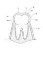
- FIG. 2 is a cross-sectional view of a molar tooth showing a state in which the orthodontic aligner of Example 1 is attached to a tooth model at an orthodontic target position in three-dimensional data.
- the configuration of the orthodontic aligner of Example 1 will be described.
- the tooth 10 shows the one before orthodontics
- the tooth model 10A shows the one at the orthodontic target position.
- the orthodontic aligner 20 is formed by a laminated modeling device based on three-dimensional data created so as to be in close contact with the tooth model 10A at the orthodontic target position.
- the orthodontic aligner 20 is attached to the tooth 10 before orthodontics, and corrects the tooth 10 to be corrected to the correction target position.
- the tooth 10 has a crown composed of an occlusal surface 11, a buccal side surface 12, and a lingual side surface 13.
- the tooth 10 is supported by the gingiva 15 surrounding the root of the tooth 10.
- the occlusal surface 11 is the end of the upper and lower teeth on the occlusal side, and refers to the occlusal surface of the molars.
- the tooth model 10A has an occlusal surface model 11A corresponding to the occlusal surface 11, a buccal lateral model 12A corresponding to the buccal lateral surface 12, and a lingual lateral model corresponding to the lingual lateral surface 13 in the molar portion. It is composed of 13A.
- the tooth model 10A is composed of a buccal lateral model 12A corresponding to the buccal lateral surface 12 and a lingual lateral model 13A corresponding to the lingual lateral surface 13 in the anterior tooth portion.
- the orthodontic aligner 20 is formed in a concave groove shape at the occlusal portion 21, the buccal side portion 22, and the lingual side portion 23 in the molar tooth portion.
- the orthodontic aligner 20 is formed in a concave groove shape on the buccal side portion 22 and the lingual side portion 23 in the anterior tooth portion (incisor portion and canine portion).
- the orthodontic aligner 20 is removable to the crown of the lower jaw.
- the orthodontic aligner 20 is formed in a groove shape so as to cover the crowns of all the teeth 10 of the lower jaw.
- the occlusal portion 21 is formed in a shape along the occlusal surface model 11A of the tooth model 10A. That is, the occlusal portion 21 is formed in a shape that covers the occlusal surface model 11A.
- the buccal side portion 22 is formed in a shape along the buccal side surface model 12A of the tooth model 10A. That is, the buccal side portion 22 is formed in a shape that covers the buccal side surface model 12A.
- the lingual side portion 23 is formed in a shape along the lingual side surface model 13A of the tooth model 10A. That is, the lingual side portion 23 is formed so as to cover the lingual side surface model 13A.
- the orthodontic aligner 20 can be colorless and transparent, for example.
- the orthodontic aligner 20 may be colored and transparent, or may be colored and opaque.
- the orthodontic aligner 20 configured in this way is attached so as to cover the crowns of all the teeth 10 of the lower jaw.
- the tooth 10 to which the orthodontic aligner 20 is attached is corrected to the correction target position.
- a plurality of orthodontic aligners 20 are prepared, and the teeth 10 are stepwise corrected to the final orthodontic target position.
- One orthodontic aligner 20 is formed into a shape capable of orthodontic by moving the tooth 10 by, for example, about 0.25 [mm].
- FIG. 3 is a flowchart illustrating a method for manufacturing the orthodontic aligner 20 according to the first embodiment.
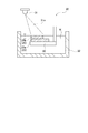
- 4 to 6 are diagrams for explaining the laminated molding process of the first embodiment.
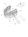
- FIG. 7 is a side view showing a modeled object produced in the laminated modeling process of Example 1.
- FIG. 8 is a diagram illustrating a peripheral edge removing step of the first embodiment.
- a three-dimensional scanner is used to scan the oral cavity of the patient to acquire three-dimensional data of the teeth 10 and gingiva 15 in the oral cavity.
- step S11 the three-dimensional data in the oral cavity acquired in the oral data acquisition step is analyzed by a computer, and the three-dimensional data of the tooth model 10A at the correction target position is created.
- step S11 the three-dimensional data in the oral cavity acquired in the oral data acquisition step is analyzed by a computer, and the three-dimensional data of the tooth model 10A at the correction target position is created.
- step S11 the three-dimensional data in the oral cavity acquired in the oral data acquisition step is analyzed by a computer, and the three-dimensional data of the tooth model 10A at the correction target position is created.
- step S11 the three-dimensional data of the tooth model 10A at the correction target position is created.
- step S12 based on the three-dimensional data of the tooth model 10A of the correction target position created in the digital setup step and the three-dimensional data of the gingival 15 acquired in the intraoral data acquisition step, Three-dimensional data of the aligner 20 for orthodontics and the peripheral edge portion 28 described later are created.
- the support is given only to the peripheral portion 28.
- the shape, thickness, density, angle, etc. of the support are appropriately adjusted according to the size, angle, and overhang portion of the three-dimensional data.
- it may have a conical shape, a columnar shape, a prismatic shape, or a wide curtain-like structure.
- It may have a branched structure or a plurality of supports may be fused in the middle, and for example, a network structure or a honeycomb structure may be formed.
- At the bottom of the support there may be a base part of the support, which is called a base or raft.
- the orthodontic aligner 20 and the peripheral edge portion 28 are used by the laminated modeling device. Create a modeled object that includes.
- the laminated molding apparatus 30 includes a container 32 containing a liquid photocurable resin W, a movable stage 33 configured to be movable in the vertical direction in the container 32, and an ultraviolet laser beam 31a. It is provided with an ultraviolet laser device 31 for irradiating light.
- the photocurable resin W for example, one containing a radically polymerizable compound such as a (meth) acrylic monomer, a polymerizable monomer containing a cationically polymerized compound such as an epoxy compound, and a photopolymerization initiator is used. can do.
- the upper surface of the movable stage 33 is at a predetermined distance from the liquid surface of the photocurable resin W (for example, 0.01 [mm]). It is arranged so that it is located only below.
- the ultraviolet laser device 31 applies the ultraviolet laser light 31a to the thin layer of the photocurable resin W on the movable stage 33 in a predetermined pattern based on the three-dimensional data of the orthodontic aligner 20 and the peripheral portion 28. Scan. As a result, the first cured layer 25a (an example of the cured layer 25) is formed.
- the movable stage 33 moves downward by a predetermined distance (for example, 0.01 [mm]). As a result, a thin layer of the photocurable resin W is formed on the first cured layer 25a.
- the ultraviolet laser device 31 applies the ultraviolet laser light 31a to the thin layer of the photocurable resin W on the first cured layer 25a, the orthodontic aligner 20 and the peripheral portion 28-3. Scan in a predetermined pattern based on the dimensional data. As a result, the second hardened layer 25b (an example of the hardened layer 25) is formed.
- a plurality of cured layers 25a, 25b, ..., 25n (25) have a predetermined stacking pitch (0.01 in Example 1).
- the modeled object 40 laminated with [mm]) is modeled.
- the model 40 is composed of an orthodontic aligner 20, a peripheral edge 28 connected to the orthodontic aligner 20, and a support 26 for supporting the peripheral edge 28.
- the cured layer 25 has a predetermined stacking pitch (0.01 [in Example 1]) in the direction D1 perpendicular to the occlusal plane S1 in the alignment direction of the portion of the orthodontic aligner 20 covering each tooth 10. It is manufactured by laminating with mm]).
- each convex hardened layer 25 is arranged so as to be formed into a continuous shape.
- the structure of the orthodontic aligner 20 is made convex toward the modeling direction (vertical direction D1 in Example 1). That is, it is preferable from the viewpoint of the stability of the molding that the molding is performed from the root to the tip of the crown.
- the orthodontic aligner 20 is modeled by the stacking modeling device 30 with the stacking direction set to the occlusal plane S1 and the direction D1.
- the orthodontic aligner 20 has a stacking mark laminated in the vertical direction D1 on the occlusal plane S1 parallel to the alignment direction of the teeth 10.
- the peripheral edge portion 28 is formed in a shape along the gingiva 15. That is, the peripheral edge portion 28 is formed so as to cover the gingiva 15.
- the peripheral edge portion 28 is connected to the lower end of the buccal side portion 22 and the lower end of the lingual side portion 23. That is, the peripheral edge 28 is connected to the root of the orthodontic aligner 20 corresponding to the root of the crown.
- the support 26 is formed in a columnar shape of, for example, about 1 [mm].
- the support 26 is connected to the lower end of the peripheral edge portion 28 to support the peripheral edge portion 28.
- step S14 In the post-treatment step (step S14), some or all unreacted substances, for example, unpolymerized monomers, are removed from the produced orthodontic aligner 20.
- peripheral edge removing step S15 the peripheral edge 28 is removed from the orthodontic aligner 20 by the laser beam 50a emitted from the laser processing machine 50. At this time, the support 26 attached to the peripheral edge portion 28 is also removed from the orthodontic aligner 20.
- the post-treatment step and the peripheral edge removal step may be reversed before and after if both effects can be sufficiently obtained.
- the post-treatment step is a post-step of the peripheral edge removing step.
- the orthodontic aligner 20 is manufactured.
- the orthodontic aligner 20 manufactured in this way forms stacking marks, but does not form support marks.
- the vertical direction D1 includes an error of about 1 °.
- the method for manufacturing the mouthpiece (orthodontic aligner 20) of Example 1 is a mouthpiece (orthodontic aligner 20) manufactured by the laminated molding apparatus 30 and mounted in the oral cavity so as to cover the teeth 10.
- a molding method including a mouthpiece (orthodontic aligner 20), a peripheral edge portion 28 connected to the mouthpiece (orthodontic aligner 20), and a support 26 for supporting the peripheral edge portion 28. It includes a laminated molding step of molding the object 40 and a peripheral edge removing step of removing the peripheral edge portion 28 from the modeled object 40 (FIG. 8).
- the support 26 is not directly formed on the mouthpiece (orthodontic aligner 20), the position of the support 26 can be easily determined. Further, since the support 26 is not directly formed on the mouthpiece (orthodontic aligner 20), it is possible to easily cope with a change in the modeling direction.
- the support mark is not formed on the occlusal portion 21 of the mouthpiece (orthodontic aligner 20)
- the target occlusal can be achieved, and the side effect of the occlusal change due to the attachment of the mouthpiece (orthodontic aligner 20) Can be reduced.
- workability is improved when cleaning the mouthpiece (orthodontic aligner 20).
- the support mark is not formed on the occlusal portion 21 of the mouthpiece (orthodontic aligner 20), it is possible to suppress the occlusal inconsistency and prevent the occurrence of problems such as malocclusion and temporomandibular joint disease.
- the peripheral edge portion 28 is connected to the root portion of the mouthpiece (orthodontic aligner 20) corresponding to the root of the crown (orthodontic aligner 20). FIG. 7).
- the peripheral edge portion 28 has a shape along the gingiva 15 (FIG. 7).
- the mouthpiece (orthodontic aligner 20) of Example 1 is a mouthpiece (orthodontic aligner 20) that is mounted in the oral cavity so as to cover the teeth 10, and is a mouthpiece (orthodontic aligner 20). 20) has a stacking mark, and the mouthpiece (orthodontic aligner 20) has no support mark (FIG. 1).
- the peripheral portion 28 was formed in a shape along the gingiva 15.
- the peripheral portion is not limited to this aspect.
- the peripheral edge portion 128 may have a shape extending from the lower end of the buccal side portion 22 and the lower end of the lingual side portion 23 in the direction D1 perpendicular to the occlusal plane S1. This makes it possible to facilitate the examination of the peripheral edge portion 128. Further, the laser processing machine 50 makes it easy to remove the peripheral edge portion 128 from the orthodontic aligner 20.
- Example 1 an example was shown in which the peripheral portion 28 was removed from the orthodontic aligner 20 by the laser light 50a emitted from the laser processing machine 50.
- tools such as nippers and scissors may be used to remove the periphery from the orthodontic aligner.
- the laminated modeling apparatus 30 is shown as an example of a stereolithography apparatus using a photocurable resin that is cured by ultraviolet rays.
- the additive manufacturing device may be a projection method in which the resin is cured and laminated using the light of a projector, or a liquid ultraviolet curable resin is jetted and cured by illuminating the ultraviolet rays for lamination. It may be an inkjet method in which heat-dissolving resin is laminated, or a fused deposition modeling method in which heat-dissolvable resins are stacked one by one, or powder sintering in which a powdery material is sintered by applying a high-power laser beam. It may be a method.
- Example 1 an example in which the orthodontic aligner 20 is formed in a concave groove shape covering the crown is shown.
- the orthodontic aligner may have a shape that covers the crown and the gingiva, or the crown and the floor portion.
- the orthodontic aligner 20 is formed in a concave groove shape so as to cover the crowns of all the teeth 10 of the mandible.
- the orthodontic aligner may be formed in a groove shape so as to cover the crown of some teeth.
- Example 1 an example in which the present invention is applied to an orthodontic aligner 20 to be attached to the crown of the lower jaw is shown. However, the present invention can be applied to an orthodontic aligner to be attached to the crown of the maxilla.
- Example 1 an example was shown in which the present invention was applied to an orthodontic aligner 20 mounted in the oral cavity so as to cover the teeth 10.
- the present invention is not limited to the orthodontic aligner, and can be applied to a mouthpiece for preventing bruxism, a mouthpiece for treating sleep apnea syndrome, a mouthpiece for whitening, and a mouthpiece for sports. it can.
- the mouthpiece of the present invention shall include a device worn so as to cover the teeth.
Landscapes
- Health & Medical Sciences (AREA)
- Animal Behavior & Ethology (AREA)
- Life Sciences & Earth Sciences (AREA)
- Veterinary Medicine (AREA)
- Public Health (AREA)
- Oral & Maxillofacial Surgery (AREA)
- Dentistry (AREA)
- Epidemiology (AREA)
- General Health & Medical Sciences (AREA)
- Engineering & Computer Science (AREA)
- General Engineering & Computer Science (AREA)
- Chemical & Material Sciences (AREA)
- Manufacturing & Machinery (AREA)
- Materials Engineering (AREA)
- Dental Tools And Instruments Or Auxiliary Dental Instruments (AREA)
Abstract
Description
図1は、実施例1の歯列矯正用アライナーと下顎を示す分解斜視図である。図2は、実施例1の歯列矯正用アライナーを、3次元データにおいて、矯正目標位置の歯モデルに装着した状態を示す臼歯の断面図である。以下、実施例1の歯列矯正用アライナーの構成を説明する。なお、図中において、歯10は矯正前のものを示し、歯モデル10Aは矯正目標位置のものを示す。
歯10は、図1に示すように、咬合面11と、頬側面12と、舌側面13と、で構成される歯冠を有する。歯10は、歯10の根元を取り巻く歯肉15によって支持される。
歯モデル10Aは、図2に示すように、臼歯部分においては、咬合面11に対応する咬合面モデル11Aと、頬側面12に対応する頬側面モデル12Aと、舌側面13に対応する舌側面モデル13Aと、で構成される。歯モデル10Aは、前歯部分においては、頬側面12に対応する頬側面モデル12Aと、舌側面13に対応する舌側面モデル13Aと、で構成される。
歯列矯正用アライナー20は、図1及び図2に示すように、臼歯部分においては、咬合部21と、頬側部22と、舌側部23とで凹溝状に形成される。歯列矯正用アライナー20は、前歯部分(切歯部分と犬歯部分)においては、頬側部22と、舌側部23とで凹溝状に形成される。歯列矯正用アライナー20は、下顎の歯冠に脱着可能になっている。歯列矯正用アライナー20は、下顎の全部の歯10の歯冠を覆うように、凹溝状に形成される。
図3は、実施例1の歯列矯正用アライナー20の製造方法を説明するフローチャートである。図4~6は、実施例1の積層造形工程を説明する図である。図7は、実施例1の積層造形工程で作製された造形物を示す側面図である。図8は、実施例1の周縁部除去工程を説明する図である。以下、実施例1の歯列矯正用アライナー20の製造方法を説明する。
口腔内データ取得工程(ステップS10)では、3次元スキャナーを用いて、患者の口腔内をスキャンして、口腔内の歯10と歯肉15の3次元データを取得する。
デジタルセットアップ工程(ステップS11)では、口腔内データ取得工程で取得した口腔内の3次元データをコンピュータで解析し、矯正目標位置の歯モデル10Aの3次元データを作成する。例えば、0.25[mm]刻みのように、段階的に最終矯正目標位置に矯正する場合は、複数の矯正目標位置の歯モデル10Aの3次元データを作成する。
3次元データ作成工程(ステップS12)では、デジタルセットアップ工程で作成した矯正目標位置の歯モデル10Aの3次元データと、口腔内データ取得工程で取得した歯肉15の3次元データと、に基づいて、歯列矯正用アライナー20と、後述する周縁部28の3次元データを作成する。
積層造形工程(ステップS13)では、3次元データ作成工程で作成した歯列矯正用アライナー20と周縁部28の3次元データに基づいて、積層造形装置によって、歯列矯正用アライナー20と周縁部28を含む造形物を造形する。
後処理工程(ステップS14)では、製造された歯列矯正用アライナー20から一部あるいは全部の未反応物、例えば未重合の単量体を除去する。後処理工程には、重力や遠心力を利用した未反応物の除去、有機溶剤による洗浄やエアブローによる未反応物の除去、乾燥、蛍光灯、ハロゲンランプ、LED光源などを用いた照射器による光重合や熱重合を施す工程を含んでもよい。
周縁部除去工程(ステップS15)では、図8に示すように、例えば、レーザ加工機50から照射されるレーザ光50aによって、周縁部28を歯列矯正用アライナー20から除去する。この際、周縁部28に付随するサポート26も、歯列矯正用アライナー20から除去される。
以下、実施例1の歯列矯正用アライナー及び歯列矯正用アライナーの製造方法の作用を説明する。実施例1のマウスピース(歯列矯正用アライナー20)の製造方法は、積層造形装置30で製造される、歯10を覆うように口腔内に装着されるマウスピース(歯列矯正用アライナー20)の製造方法であって、マウスピース(歯列矯正用アライナー20)と、マウスピース(歯列矯正用アライナー20)に接続する周縁部28と、周縁部28を支持するサポート26と、を有する造形物40を造形する積層造形工程と、造形物40から周縁部28を除去する周縁部除去工程と、を含む(図8)。
Claims (4)
- 積層造形装置で製造される、歯を覆うように口腔内に装着されるマウスピースの製造方法であって、
前記マウスピースと、前記マウスピースに接続する周縁部と、前記周縁部を支持するサポートと、を有する造形物を造形する積層造形工程と、
前記造形物から前記周縁部を除去する周縁部除去工程と、を含む
ことを特徴とする、マウスピースの製造方法。 - 前記周縁部は、歯冠の根元に対応する、前記マウスピースの根元部に接続される
ことを特徴とする、請求項1に記載のマウスピースの製造方法。 - 前記周縁部は、歯肉に沿った形状である
ことを特徴とする、請求項1又は2に記載のマウスピースの製造方法。 - 歯を覆うように口腔内に装着されるマウスピースであって、
前記マウスピースは、積層痕を有し、
前記マウスピースは、サポート痕を有しない
ことを特徴とする、マウスピース。
Priority Applications (4)
| Application Number | Priority Date | Filing Date | Title |
|---|---|---|---|
| US17/617,959 US20220257345A1 (en) | 2019-06-12 | 2020-06-11 | Mouthpiece and mouthpiece manufacturing method |
| JP2021526134A JP7365411B2 (ja) | 2019-06-12 | 2020-06-11 | マウスピース及びマウスピースの製造方法 |
| EP20823495.5A EP3984497B1 (en) | 2019-06-12 | 2020-06-11 | METHOD FOR MANUFACTURING AN ORAL APPLIANCE |
| CN202080042754.7A CN114007541B (zh) | 2019-06-12 | 2020-06-11 | 齿套以及齿套的制造方法 |
Applications Claiming Priority (2)
| Application Number | Priority Date | Filing Date | Title |
|---|---|---|---|
| JP2019-109888 | 2019-06-12 | ||
| JP2019109888 | 2019-06-12 |
Publications (1)
| Publication Number | Publication Date |
|---|---|
| WO2020250976A1 true WO2020250976A1 (ja) | 2020-12-17 |
Family
ID=73781497
Family Applications (1)
| Application Number | Title | Priority Date | Filing Date |
|---|---|---|---|
| PCT/JP2020/023025 Ceased WO2020250976A1 (ja) | 2019-06-12 | 2020-06-11 | マウスピース及びマウスピースの製造方法 |
Country Status (5)
| Country | Link |
|---|---|
| US (1) | US20220257345A1 (ja) |
| EP (1) | EP3984497B1 (ja) |
| JP (1) | JP7365411B2 (ja) |
| CN (1) | CN114007541B (ja) |
| WO (1) | WO2020250976A1 (ja) |
Cited By (2)
| Publication number | Priority date | Publication date | Assignee | Title |
|---|---|---|---|---|
| CN112872971A (zh) * | 2021-01-05 | 2021-06-01 | 杨洁 | 隐形正畸牙套磨抛机及隐形正畸牙套的加工方法 |
| CN115230167A (zh) * | 2021-04-24 | 2022-10-25 | 清锋(北京)科技有限公司 | 一种3d打印制备的齿科器械及其3d打印支撑件 |
Families Citing this family (3)
| Publication number | Priority date | Publication date | Assignee | Title |
|---|---|---|---|---|
| CN114404078B (zh) * | 2022-01-04 | 2023-05-23 | 深圳技术大学 | 一种隐形矫治器的制备方法及隐形矫治器 |
| US20240090977A1 (en) * | 2022-09-19 | 2024-03-21 | Maria Olinta Zurita Dehó | Orthodontic aligner comprising bite plate |
| WO2025122507A1 (en) * | 2023-12-04 | 2025-06-12 | Align Technology, Inc. | Additively manufactured objects with accessible supports and associated methods |
Citations (6)
| Publication number | Priority date | Publication date | Assignee | Title |
|---|---|---|---|---|
| JP2006081747A (ja) | 2004-09-16 | 2006-03-30 | Osaka Univ | バイトスプリントの製造方法 |
| JP2013081785A (ja) * | 2011-10-12 | 2013-05-09 | Ormco Corp | 歯列矯正アライナー器具の直接製造 |
| JP2017159104A (ja) * | 2006-08-22 | 2017-09-14 | ジャック・キース・ヒリアード | 歯科矯正アライナ製造装置および方法 |
| JP2017537687A (ja) * | 2014-11-12 | 2017-12-21 | アライン テクノロジー, インコーポレイテッド | 隔離セグメントを備える歯科矯正アライナー |
| JP2018094245A (ja) | 2016-12-15 | 2018-06-21 | 岡本化学工業株式会社 | 歯科矯正用アライナー及びその製造方法 |
| JP2019109888A (ja) | 2017-12-18 | 2019-07-04 | ソウル大学校産学協力団Seoul National University R&Db Foundation | 二重閉回路ブレイン−マシーンインターフェースシステム及びその方法 |
Family Cites Families (10)
| Publication number | Priority date | Publication date | Assignee | Title |
|---|---|---|---|---|
| EP2919705B1 (en) * | 2012-11-14 | 2021-06-23 | DENTSPLY SIRONA Inc. | Three-dimensional fabricating material systems for producing dental products |
| EP2842980B1 (en) * | 2013-08-09 | 2021-05-05 | DSM IP Assets B.V. | Low-viscosity liquid radiation curable dental aligner mold resin compositions for additive manufacturing |
| JP6451088B2 (ja) | 2014-06-03 | 2019-01-16 | コニカミノルタ株式会社 | 立体造形物の製造方法 |
| US10709530B2 (en) * | 2015-02-03 | 2020-07-14 | Mitsui Chemicals, Inc. | Photocurable composition, denture base, and plate denture |
| CN105769356A (zh) * | 2016-04-28 | 2016-07-20 | 华南理工大学 | 一种个性化无托槽隐形矫治器光固化增材制造方法 |
| FR3057156B1 (fr) * | 2016-10-10 | 2022-07-15 | D & D | Appareil orthodontique mono-materiau |
| US10575925B2 (en) * | 2017-05-19 | 2020-03-03 | Structo Pte Ltd | Method and apparatus for forming an orthodontic aligner |
| EP4215151B1 (en) * | 2018-05-03 | 2024-04-24 | DENTSPLY SIRONA Inc. | Methods of three dimensional printing for fabricating a dental appliance |
| AU2020247931B2 (en) * | 2019-03-25 | 2025-09-11 | Align Technology, Inc. | Various structured supports for 3D printed aligners/mouth pieces |
| US11511485B2 (en) * | 2019-04-02 | 2022-11-29 | Align Technology, Inc. | 3D printed objects with selective overcure regions |
-
2020
- 2020-06-11 US US17/617,959 patent/US20220257345A1/en active Pending
- 2020-06-11 JP JP2021526134A patent/JP7365411B2/ja active Active
- 2020-06-11 EP EP20823495.5A patent/EP3984497B1/en active Active
- 2020-06-11 WO PCT/JP2020/023025 patent/WO2020250976A1/ja not_active Ceased
- 2020-06-11 CN CN202080042754.7A patent/CN114007541B/zh active Active
Patent Citations (6)
| Publication number | Priority date | Publication date | Assignee | Title |
|---|---|---|---|---|
| JP2006081747A (ja) | 2004-09-16 | 2006-03-30 | Osaka Univ | バイトスプリントの製造方法 |
| JP2017159104A (ja) * | 2006-08-22 | 2017-09-14 | ジャック・キース・ヒリアード | 歯科矯正アライナ製造装置および方法 |
| JP2013081785A (ja) * | 2011-10-12 | 2013-05-09 | Ormco Corp | 歯列矯正アライナー器具の直接製造 |
| JP2017537687A (ja) * | 2014-11-12 | 2017-12-21 | アライン テクノロジー, インコーポレイテッド | 隔離セグメントを備える歯科矯正アライナー |
| JP2018094245A (ja) | 2016-12-15 | 2018-06-21 | 岡本化学工業株式会社 | 歯科矯正用アライナー及びその製造方法 |
| JP2019109888A (ja) | 2017-12-18 | 2019-07-04 | ソウル大学校産学協力団Seoul National University R&Db Foundation | 二重閉回路ブレイン−マシーンインターフェースシステム及びその方法 |
Non-Patent Citations (1)
| Title |
|---|
| See also references of EP3984497A4 |
Cited By (2)
| Publication number | Priority date | Publication date | Assignee | Title |
|---|---|---|---|---|
| CN112872971A (zh) * | 2021-01-05 | 2021-06-01 | 杨洁 | 隐形正畸牙套磨抛机及隐形正畸牙套的加工方法 |
| CN115230167A (zh) * | 2021-04-24 | 2022-10-25 | 清锋(北京)科技有限公司 | 一种3d打印制备的齿科器械及其3d打印支撑件 |
Also Published As
| Publication number | Publication date |
|---|---|
| EP3984497A4 (en) | 2023-01-18 |
| JP7365411B2 (ja) | 2023-10-19 |
| CN114007541A (zh) | 2022-02-01 |
| US20220257345A1 (en) | 2022-08-18 |
| CN114007541B (zh) | 2023-09-01 |
| EP3984497B1 (en) | 2025-04-30 |
| EP3984497C0 (en) | 2025-04-30 |
| JPWO2020250976A1 (ja) | 2020-12-17 |
| EP3984497A1 (en) | 2022-04-20 |
Similar Documents
| Publication | Publication Date | Title |
|---|---|---|
| WO2020250976A1 (ja) | マウスピース及びマウスピースの製造方法 | |
| US20250178276A1 (en) | Overcure regions for 3d printed objects in dentistry | |
| JP7807917B2 (ja) | マウスピース及びマウスピースの製造方法 | |
| CN104644276B (zh) | 制造牙齿矫治器的方法以及牙齿矫治器 | |
| US11684462B2 (en) | Dental prosthesis | |
| KR102426017B1 (ko) | 치아 투명교정에서 어태치먼트의 올바른 형태와 정확한 위치 부착을 위한 지그 일체형 어태치먼트 성형틀의 제조방법 및 이를 이용한 지그 일체형 어태치먼트 성형틀 | |
| US12251276B2 (en) | Additively manufactured denture base with bracing body | |
| JP2018094245A (ja) | 歯科矯正用アライナー及びその製造方法 | |
| KR101612846B1 (ko) | 플라스틱 치아교정장치의 예비성형체 및 그 제조방법 | |
| EP4424276A1 (en) | Mill blank for dentures, cut member for front tooth, and production method for dentures | |
| WO2020250974A1 (ja) | 歯列矯正用アライナー及びその製造方法 | |
| KR101612841B1 (ko) | 플라스틱 치아교정장치의 제조방법 | |
| WO2019193650A1 (ja) | 歯科矯正用アライナー及びその製造方法 | |
| RU2838389C2 (ru) | Заготовка для зубных протезов, подлежащий резке элемент для передних зубов и способ выполнения зубных протезов | |
| WO2022044929A1 (ja) | 歯科造形物の画像データ作成方法、歯科造形物の画像データ作成装置、歯科造形物の画像データ作成プログラム、歯科造形物の製造方法及び歯科造形物 | |
| US20230363863A1 (en) | Systems, methods and devices for providing customized orthodontics devices and techniques | |
| KR20160144850A (ko) | 플라스틱 치아교정장치의 제조방법 | |
| WO2024228376A1 (ja) | 歯科治療用インデックス、歯科治療用インデックス固定ホルダー、歯科治療セット、歯科治療用インデックス三次元データ生成方法、及び歯科治療用インデックス作成用データ | |
| KR20170132630A (ko) | 투명 디바이스의 두께 측정 방법 | |
| HK1250901B (zh) | 用於制作牙科器具或壳体的系统和方法 | |
| JP2006255128A (ja) | 模型歯牙位置調節具 |
Legal Events
| Date | Code | Title | Description |
|---|---|---|---|
| 121 | Ep: the epo has been informed by wipo that ep was designated in this application |
Ref document number: 20823495 Country of ref document: EP Kind code of ref document: A1 |
|
| ENP | Entry into the national phase |
Ref document number: 2021526134 Country of ref document: JP Kind code of ref document: A |
|
| NENP | Non-entry into the national phase |
Ref country code: DE |
|
| ENP | Entry into the national phase |
Ref document number: 2020823495 Country of ref document: EP Effective date: 20220112 |
|
| WWG | Wipo information: grant in national office |
Ref document number: 2020823495 Country of ref document: EP |