WO2020255334A1 - 遠心ファンおよび回転電機 - Google Patents
遠心ファンおよび回転電機 Download PDFInfo
- Publication number
- WO2020255334A1 WO2020255334A1 PCT/JP2019/024510 JP2019024510W WO2020255334A1 WO 2020255334 A1 WO2020255334 A1 WO 2020255334A1 JP 2019024510 W JP2019024510 W JP 2019024510W WO 2020255334 A1 WO2020255334 A1 WO 2020255334A1
- Authority
- WO
- WIPO (PCT)
- Prior art keywords
- blades
- rotation direction
- blade
- centrifugal fan
- rotation
- Prior art date
- Legal status (The legal status is an assumption and is not a legal conclusion. Google has not performed a legal analysis and makes no representation as to the accuracy of the status listed.)
- Ceased
Links
Images


Classifications
-
- F—MECHANICAL ENGINEERING; LIGHTING; HEATING; WEAPONS; BLASTING
- F04—POSITIVE - DISPLACEMENT MACHINES FOR LIQUIDS; PUMPS FOR LIQUIDS OR ELASTIC FLUIDS
- F04D—NON-POSITIVE-DISPLACEMENT PUMPS
- F04D29/00—Details, component parts, or accessories
- F04D29/26—Rotors specially for elastic fluids
- F04D29/28—Rotors specially for elastic fluids for centrifugal or helico-centrifugal pumps for radial-flow or helico-centrifugal pumps
- F04D29/30—Vanes
-
- F—MECHANICAL ENGINEERING; LIGHTING; HEATING; WEAPONS; BLASTING
- F04—POSITIVE - DISPLACEMENT MACHINES FOR LIQUIDS; PUMPS FOR LIQUIDS OR ELASTIC FLUIDS
- F04D—NON-POSITIVE-DISPLACEMENT PUMPS
- F04D29/00—Details, component parts, or accessories
- F04D29/26—Rotors specially for elastic fluids
- F04D29/28—Rotors specially for elastic fluids for centrifugal or helico-centrifugal pumps for radial-flow or helico-centrifugal pumps
- F04D29/281—Rotors specially for elastic fluids for centrifugal or helico-centrifugal pumps for radial-flow or helico-centrifugal pumps for fans or blowers
-
- F—MECHANICAL ENGINEERING; LIGHTING; HEATING; WEAPONS; BLASTING
- F04—POSITIVE - DISPLACEMENT MACHINES FOR LIQUIDS; PUMPS FOR LIQUIDS OR ELASTIC FLUIDS
- F04D—NON-POSITIVE-DISPLACEMENT PUMPS
- F04D17/00—Radial-flow pumps, e.g. centrifugal pumps; Helico-centrifugal pumps
- F04D17/08—Centrifugal pumps
-
- F—MECHANICAL ENGINEERING; LIGHTING; HEATING; WEAPONS; BLASTING
- F04—POSITIVE - DISPLACEMENT MACHINES FOR LIQUIDS; PUMPS FOR LIQUIDS OR ELASTIC FLUIDS
- F04D—NON-POSITIVE-DISPLACEMENT PUMPS
- F04D25/00—Pumping installations or systems
- F04D25/02—Units comprising pumps and their driving means
- F04D25/06—Units comprising pumps and their driving means the pump being electrically driven
-
- F—MECHANICAL ENGINEERING; LIGHTING; HEATING; WEAPONS; BLASTING
- F04—POSITIVE - DISPLACEMENT MACHINES FOR LIQUIDS; PUMPS FOR LIQUIDS OR ELASTIC FLUIDS
- F04D—NON-POSITIVE-DISPLACEMENT PUMPS
- F04D29/00—Details, component parts, or accessories
- F04D29/26—Rotors specially for elastic fluids
- F04D29/28—Rotors specially for elastic fluids for centrifugal or helico-centrifugal pumps for radial-flow or helico-centrifugal pumps
- F04D29/281—Rotors specially for elastic fluids for centrifugal or helico-centrifugal pumps for radial-flow or helico-centrifugal pumps for fans or blowers
- F04D29/282—Rotors specially for elastic fluids for centrifugal or helico-centrifugal pumps for radial-flow or helico-centrifugal pumps for fans or blowers the leading edge of each vane being substantially parallel to the rotation axis
-
- F—MECHANICAL ENGINEERING; LIGHTING; HEATING; WEAPONS; BLASTING
- F04—POSITIVE - DISPLACEMENT MACHINES FOR LIQUIDS; PUMPS FOR LIQUIDS OR ELASTIC FLUIDS
- F04D—NON-POSITIVE-DISPLACEMENT PUMPS
- F04D29/00—Details, component parts, or accessories
- F04D29/66—Combating cavitation, whirls, noise, vibration or the like; Balancing
- F04D29/661—Combating cavitation, whirls, noise, vibration or the like; Balancing especially adapted for elastic fluid pumps
- F04D29/666—Combating cavitation, whirls, noise, vibration or the like; Balancing especially adapted for elastic fluid pumps by means of rotor construction or layout, e.g. unequal distribution of blades or vanes
-
- H—ELECTRICITY
- H02—GENERATION; CONVERSION OR DISTRIBUTION OF ELECTRIC POWER
- H02K—DYNAMO-ELECTRIC MACHINES
- H02K9/00—Arrangements for cooling or ventilating
- H02K9/02—Arrangements for cooling or ventilating by ambient air flowing through the machine
- H02K9/04—Arrangements for cooling or ventilating by ambient air flowing through the machine having means for generating a flow of cooling medium
- H02K9/06—Arrangements for cooling or ventilating by ambient air flowing through the machine having means for generating a flow of cooling medium with fans or impellers driven by the machine shaft
-
- F—MECHANICAL ENGINEERING; LIGHTING; HEATING; WEAPONS; BLASTING
- F04—POSITIVE - DISPLACEMENT MACHINES FOR LIQUIDS; PUMPS FOR LIQUIDS OR ELASTIC FLUIDS
- F04D—NON-POSITIVE-DISPLACEMENT PUMPS
- F04D29/00—Details, component parts, or accessories
- F04D29/26—Rotors specially for elastic fluids
- F04D29/32—Rotors specially for elastic fluids for axial flow pumps
- F04D29/325—Rotors specially for elastic fluids for axial flow pumps for axial flow fans
- F04D29/328—Rotors specially for elastic fluids for axial flow pumps for axial flow fans with unequal distribution of blades around the hub
-
- F—MECHANICAL ENGINEERING; LIGHTING; HEATING; WEAPONS; BLASTING
- F05—INDEXING SCHEMES RELATING TO ENGINES OR PUMPS IN VARIOUS SUBCLASSES OF CLASSES F01-F04
- F05D—INDEXING SCHEME FOR ASPECTS RELATING TO NON-POSITIVE-DISPLACEMENT MACHINES OR ENGINES, GAS-TURBINES OR JET-PROPULSION PLANTS
- F05D2240/00—Components
- F05D2240/20—Rotors
- F05D2240/30—Characteristics of rotor blades, i.e. of any element transforming dynamic fluid energy to or from rotational energy and being attached to a rotor
- F05D2240/301—Cross-sectional characteristics
-
- F—MECHANICAL ENGINEERING; LIGHTING; HEATING; WEAPONS; BLASTING
- F05—INDEXING SCHEMES RELATING TO ENGINES OR PUMPS IN VARIOUS SUBCLASSES OF CLASSES F01-F04
- F05D—INDEXING SCHEME FOR ASPECTS RELATING TO NON-POSITIVE-DISPLACEMENT MACHINES OR ENGINES, GAS-TURBINES OR JET-PROPULSION PLANTS
- F05D2240/00—Components
- F05D2240/20—Rotors
- F05D2240/30—Characteristics of rotor blades, i.e. of any element transforming dynamic fluid energy to or from rotational energy and being attached to a rotor
- F05D2240/304—Characteristics of rotor blades, i.e. of any element transforming dynamic fluid energy to or from rotational energy and being attached to a rotor related to the trailing edge of a rotor blade
Definitions
- This application relates to a centrifugal fan and a rotary electric machine.
- the centrifugal fan sucks fluid from the direction of the axis of rotation with a rotary impeller and discharges it in the direction of the radius of gyration, and is used for the purpose of transporting liquids such as air and other gases and refrigerants.
- Patent Document 1 includes a plurality of blades arranged in the circumferential direction, a disk-shaped or bowl-shaped hub at one end in the axial direction of the blade, and an annular shroud at the other end in the axial direction of the blade. Centrifugal fans are disclosed. Further, in Patent Document 1, auxiliary blades are provided on the annular shroud, and the shape or spacing of the blades or auxiliary blades is changed to improve the air volume performance and reduce noise.
- Patent Document 1 discloses that the frequency of noise generated by a centrifugal fan is modulated and noise of a specific frequency is reduced by randomly arranging the distance between blades and auxiliary blades or changing the number of blades.
- a centrifugal fan having a conventional structure for example, when the number of blades is Z and the frequency generated from the centrifugal fan is modulated by changing from the number of blades Z, a component having a large noise value modulated to a frequency smaller than the number of blades Z. And, a component having a large noise value modulated in a frequency band larger than the number of blades Z is generated at the same time, which causes a problem of causing discomfort.
- nz noise indicated by the frequency of n ⁇ Z, where n is the rotation speed, and is modulated to the frequencies Z-1, Z-2, ..., Which are smaller than the number of blades Z.
- n is the rotation speed
- a component having a large noise value and a component having a large noise value modulated in a frequency band of Z + 1, Z + 2, ... which is larger than the number of blades Z are generated at the same time.
- the noise in the low frequency band is inconspicuous because it is masked by the engine noise, and there is a large discomfort when the noise value in the high frequency band is large. Was occurring.
- An object of the present application is to solve such a conventional problem, and to reduce the noise value in a high frequency band without reducing the air volume in a centrifugal fan having a plurality of blades at irregular intervals. To do.
- the centrifugal fan disclosed in the present application is a centrifugal fan including a main plate having a rotation center and a plurality of blades extending from the main plate in the direction of a rotation axis passing through the rotation center, and the plurality of blades are at least a part thereof.
- the length direction of the blades extends from the inner peripheral side to the outer peripheral side of the main plate, and among the plurality of blades, the blades adjacent to each other in the rotational direction
- the shape of the blade on the rear side in the rotation direction and the shape of the blade on the front side in the rotation direction and the outer peripheral side of the written blade are different, and the blade on the rear side in the rotation direction is in the rotation direction.
- the action of discharging the fluid in the outer peripheral direction is smaller than that of the blade on the front side.
- centrifugal fan disclosed in the present application, it is possible to reduce the noise value in the high frequency band without reducing the air volume.
- FIG. It is a block diagram which shows the outline of the centrifugal fan which concerns on Embodiment 1.
- FIG. It is a partially enlarged view of the centrifugal fan which concerns on Embodiment 1.
- FIG. It is sectional drawing in the XX'direction in FIG. Another partially enlarged view of the centrifugal fan according to the first embodiment.
- FIG. It is a partially enlarged view of another centrifugal fan which concerns on Embodiment 1.
- FIG. It is a figure which showed the nz noise generated from a centrifugal fan.
- It shows the nz noise reduction effect of the centrifugal fan which concerns on Embodiment 5.
- It is a partial sectional view which showed the outline of the alternator for a vehicle which concerns on Embodiment 9.
- FIG. It is a figure which showed the partial structure of the rotor and the centrifugal fan of the alternator for a vehicle which concerns on Embodiment 9.
- FIG. 1 is a diagram showing a schematic configuration of a centrifugal fan according to the first embodiment.
- the centrifugal fan 1 is erected on an annular main plate 2, a plurality of arm-shaped plates 3 formed so as to extend from the outer periphery of the main plate 2 to the same surface as the main plate 2, and the edges of the respective arm-shaped plates 3.
- the blades 4 are provided.
- the main plate 2 has a center of rotation near the center thereof, and a rotation axis is provided so as to pass through the center of rotation and be orthogonal to the main surface of the main plate 2. Further, the main plate 2 is attached to a rotating object, for example, a rotor of a rotating electric machine. As shown in FIG. 1, a hole is provided in the central portion of the main plate 2 for passing, for example, a shaft (see the ninth embodiment described later) which is a rotation shaft of a rotary electric machine.
- the central portion of the main plate 2 may have a bowl-like shape that bulges in the axial direction in which the blades 4 are formed. Ribs or protrusions for reinforcing a part of the main plate 2 may be provided. Further, when it is attached to a rotating electric machine, a notch for positioning with the rotor may be provided.
- the arm-shaped plate 3 is formed so as to extend outward from a part of the outer circumference of the main plate 2 and is in the same plane as the main plate 2.
- the arm-shaped plate 3 may be provided with ribs for strengthening the strength.
- the blade 4 has a shape that rises approximately at a right angle in the direction of the rotation axis from the outer peripheral end of the arm-shaped plate 3, and is a portion that is approximately parallel to the rotation axis.
- the blade 4 does not have to be formed at a right angle to the main plate 2, and may be set so as to have a constant angle with the main plate 2.
- the main plate 2 or the arm-shaped plate 3 extending from the main plate 2 may be provided with cooling holes 5, and the shape of the cooling holes 5 may be circular, elliptical, substantially polygonal, or may be provided in plurality. .. Further, when a plurality of cooling holes 5 are provided, the shape of each cooling hole may be different. Further, in the cooling holes 5 provided in the main plate 2 and the arm-shaped plate 3 extending from the main plate, the hole ends on the blade 4 side are rounded or chamfered so as to reduce the ventilation resistance of the flow sucked into the rotor. It may be provided.
- FIG. 2 shows an enlarged view of the blade 4_3 portion in FIG. 1
- FIG. 3 shows a cross-sectional view in the XX'direction in FIG. The height of the blade 4 in the axial direction is low at the front edge (X side) in the rotation direction and high at the rear edge (X'side) to reduce the collision of wind W at the front edge.
- the blades 4 are formed at irregular intervals in the rotation direction.
- the unequal interval is a form in which the angle P formed by the outer peripheral ends of adjacent blades sandwiching the center of rotation when viewed from the direction of the rotation axis is not constant between the blades.
- the angles P formed by sandwiching the rotation center between all the blades are different. It should be noted that at least a part thereof may include an arrangement in which the intervals between adjacent blades are unequal. Further, it may include a configuration in which the same angle P is formed between different blades among a large number of blades, but it is possible that more than half of the types of angles P are included with respect to the number of blades. desirable.
- FIGS. 4 and 5 show enlarged views in the vicinity of the blades 4_1 and 4_2.
- the number of blades of the centrifugal fan 1 is Z
- the angle between the outermost outer peripheral ends of two adjacent blades when viewed from the rotation axis direction with respect to the rotation center O is the smallest angle P1.
- P2, ..., PZ be the angles of two blades adjacent to each other in order from the angle P1 in the counter-rotation direction.
- the blades 4_1, 4_2, ..., 4_Z provided in the counter-rotation direction from the front side in the rotation direction of P1 are used.
- the outer diameters of the blades 4_1, 4_2, ..., 4_Z on the cross section perpendicular to the rotation axis are R1, R2, ..., RZ.
- the tangent line of the circle centered on the rotation center O at the outer peripheral end of each blade that is, the tangent line of the outer end of the circle whose radius is R1, R2, ..., RZ, respectively. Therefore, the angle formed by the tangent that extends the inclination near the outer peripheral end of each blade from the outer peripheral end with reference to the tangent extending from the outer peripheral end to the rear side in the rotation direction is the exit angles ⁇ 1, ⁇ 2 ..., ⁇ Z. To do.
- the outer peripheral side of the blade is a curved surface
- select two points (Q1 and Q2) near the end for example, from a short range of about 2 mm to 3 mm from the end, and connect the two points with a straight line.
- the exit angles ⁇ 1, ⁇ 2 ..., ⁇ Z may be obtained by using the extended line as a tangent to the extension.
- the length at which the blade 4 is most distant from the main plate 2 in the rotation axis direction is defined as the height H of the blade 4, and the height corresponds to each blade 4_1, 4_2, ..., 4_Z.
- H1, H2, ..., HZ the radius of warpage on the outer peripheral side on the cross section perpendicular to the rotation axis.
- S1 the radius of warpage corresponding to each blade 4_1, 4_2, ..., 4_Z.
- the inner diameter side of the blade has a concave shape in the rotation direction side
- the outer peripheral side has a convex shape
- the inner peripheral side and the outer peripheral side are smoothly connected.
- the warp radius S is the warp radius on the outer peripheral side of each blade.
- the warp radius S2 of the blade 4_2 on the rear side in the rotation direction of the pair of two blades having the smallest distance between the blades adjacent to each other in the rotation direction is smaller than the warp radius of all the other blades. .. That is, the blade 4_2 is a blade set to S2 ⁇ (the minimum value of S1, S3, ..., SZ).
- the two blades having the smallest distance between adjacent blades are a combination of blades forming an angle P1 in which the outermost peripheral end of the two blades sandwiches the rotation center O and the angle P is the smallest.
- the warp radius S2 of the blade 4_2 on the rear side in the rotation direction is set to be at least smaller than the warp radius S1 of the blade 4_1 on the front side in the rotation direction among the pair of two blades having the smallest distance between the blades adjacent to each other in the rotation direction. do it.
- the warp radius S2 of the blade 4_2 is set to be smaller than the warp radius S2 of all the blades or smaller than the warp radius S1 of the blade 4_1, the flow blown out from the blade 4_2 in the centrifugal direction is affected by the other blades. It becomes smaller than the above, and the sudden change in the flow velocity that occurs before and after the blade 4_2 is suppressed.
- the nz noise is a discrete frequency noise caused by the rotation speed generated from the centrifugal fan, and is described by a frequency of n ⁇ Z, where n is the rotation speed and Z is the number of blades.
- n the rotation speed
- Z the number of blades.
- the warp radius of the blades on the rear side of the two blades 4_1 and 4_2 having the smallest spacing is made smaller than the warp radius of the blades on the front side to suppress a sudden change in flow velocity.
- the warp radius of the blades on the rear side of the two blades having the smallest distance is made smaller than the warp radius of at least the front blades.
- the shape in which the blades on the rear side suppress a sudden change in the flow velocity means a shape in which the action of releasing air to the outer periphery as blades is smaller than that on the blades on the front side.
- the air volume may decrease as a centrifugal fan.
- the warp radius S2 on the outer peripheral side of the blades on the rear side in the rotation direction of the two blades having the smallest spacing is half or less of the warp radius S1 on the outer peripheral side of the blades on the front side. It is even better if it is 1/3 or less.
- the warp radius of the outer peripheral side of the two blades with the second or third smallest distance on the rear side in the rotation direction is on the front side. It may be smaller than the warp radius on the outer peripheral side of the blade.
- the pair of two blades, the blades 4_4 and 4_5 in FIG. 1, which are located approximately opposite to the center of the pair of blades having the narrowest spacing, are placed at the second or third smallest spacing. It is a pair of feathers.
- the high frequency component is reduced by setting a similar warp radius relationship, that is, S5 ⁇ S4, S5 ⁇ S4 ⁇ 1/2, or S5 ⁇ S4 ⁇ 1/3. The effect can be further improved.
- FIGS. 1 and 4 show an example in which the outer diameters R1 and R2 of the two blades having the smallest distance between adjacent blades, that is, the blades 4_1 and 4_2 forming the angle P1, are set to R1> R2.
- the blades are arranged at unequal intervals, and the warp radius of the outer peripheral side of the blades on the rear side in the rotation direction of the two blades having the smallest distances. Since S2 is smaller than the warp radius S1 on the outer peripheral side of the blades on the front side, the same air volume can be realized as the same number of centrifugal fans having blades at equal intervals, and the high frequency component of noise is higher than that of the conventional non-equidistant blades. Since it is reduced, the effect of the A characteristic correction becomes large, and the A characteristic sound pressure level (A-weighted sound pressure level) of the noise generated from the centrifugal fan can be greatly reduced.
- the positions of the arm-shaped plates 3 are also unevenly spaced in the rotation direction, and the ring-shaped portion of the main plate 2 is not exposed between the two arm-shaped plates 3 that are close to each other. That is, the base portion of the two arm-shaped plates 3 connected to the main plate 2 may be partially connected.
- the blade 4 Since the blade 4 is provided at the outer peripheral end of the arm-shaped plate 3 extending in the radial direction, the blade 4 is formed together with the arm-shaped plate 3 from the main plate 2 by making a notch in the main plate 2 and performing a bending process to raise a part of the blade 4. It is also possible to form by bending a continuous plate. However, the blade 4 does not have to be provided at the outer peripheral end of the arm-shaped plate 3 extending in the radial direction, and may be inside the arm-shaped plate 3.
- the cooling holes 5 may be provided in all the arm-shaped plates 3, but only one may be provided. Not only the cooling hole 5, but also a part of the arm-shaped plate 3 in the radial direction may be thinned in order to increase the air flow flowing in the axial direction.
- the arm-shaped plate 3 not provided with the cooling hole 5 can be provided with a notch at the front edge or the trailing edge of rotation in the radial direction to increase the air flow flowing in the axial direction. It is desirable that the centrifugal fan 1 is installed so that air can easily flow through the cooling hole 5 in the direction opposite to the direction in which the blade 4 is inclined.
- the air that has passed through the cooling hole 5 escapes in the direction of the rotation axis of the centrifugal fan, and a part of the air flows in the centrifugal direction as the main plate 2 rotates. Further, the weight can be reduced by providing the cooling holes 5 in the main plate 2 and the arm-shaped plate 3. Further, as described above, by providing more cooling holes 5 in places where the installation density of the arm-shaped plate 3 is high, the center of gravity of the centrifugal fan 1 can be brought closer to the center of rotation, and the imbalance can be corrected. ..
- Embodiment 2 the centrifugal fan according to the second embodiment will be described.
- the blades having a narrow spacing generate a high frequency component
- the blades having the smallest spacing have a radius of warpage on the outer peripheral side of the blades behind the two blades having the smallest spacing.
- an example of adjusting the outlet angle ⁇ 2 of the blades 4_2 on the rear side shown in FIGS. 1, 4 and 5 will be described.
- the outlet angle ⁇ 2 of the blade 4_2 behind the two blades with the smallest distance is smaller than the outlet angles of all the other blades, that is, ⁇ 2 ⁇ (minimum value of ⁇ 1, ⁇ 3, ..., ⁇ Z) Set to.
- the outlet angle ⁇ 2 of the blade 4_2 on the rear side in the rotation direction may be smaller than at least the exit angle ⁇ 1 of the blade 4_1 on the front side, so that 0 ⁇ 2 ⁇ 1.
- ⁇ 2 is in the range of 20 ° to 70 °, and it is preferable that the angle is about 5 ° to 15 ° smaller than that of ⁇ 1.
- the outer diameter R2 of the blade on the rear side in the rotation direction among the two blades having the smallest spacing is assumed to be 90 to 99% of the outer diameter R1 of the blade on the front side. Desirably, 95-98% is even better.
- the blades are arranged at unequal intervals, and the outer diameter R2 of the blades on the rear side in the rotation direction among the two blades having the smallest distance is set. Since the outer diameter R1 of the blades on the front side is at least smaller than that of the conventional blades having irregular intervals, the high frequency component of noise is reduced.
- Embodiment 4 the centrifugal fan according to the fourth embodiment will be described.
- the height H2 of the blades 4_2 behind the two blades having the smallest distance is opposed to the fact that the blades having a narrow distance generate a high frequency component.
- the blade height H2 of the blade 4_2 behind the two blades having the smallest distance is smaller than the blade heights of all the other blades, that is, H2 ⁇ (minimum value of H1, H3, ..., HZ).
- H2 ⁇ (minimum value of H1, H3, ..., HZ).
- the height H2 of the blade 4_2 on the rear side in the rotation direction of the two blades having the smallest distance is at least smaller than the height H1 of the blade 4_1 on the front side, and is 90 to 99% of the height H1. Desirably, 95-98% is even better.
- the blades are arranged at unequal intervals, and the height H2 of the blades on the rear side in the rotation direction among the two blades having the smallest distance is set. Since the height of the blades on the front side is made smaller than H1, the high frequency component of noise is reduced as compared with the conventional non-equidistant blades.
- FIG. 7 is a diagram showing the nz noise reduction effect of the centrifugal fan according to the fifth embodiment.
- the horizontal axis is the left side of the above equation (1), and the vertical axis is the difference obtained by subtracting the logarithmic sum of the low frequency components from the logarithmic sum of the high frequency components of the nz noise, and the outer peripheral shape of the two blades with the smallest spacing is tested. It is a graph which plotted the result.
- the position of the arrow in FIG. 7 corresponds to the right side of the above equation (1).
- the outer peripheral shape of the two blades having the smallest distance is defined by the equation (1), but the outer peripheral shape of the blade 4_2 behind the two blades having the smallest distance is the front side. It is desirable that the same relationship as in the above formula (1) is satisfied for the other blades as defined in the formula (1) for the blade 4-1 in the above. That is, it is desirable to satisfy the following equation (2).
- the centrifugal fan according to the sixth embodiment will be described.
- the blades having a narrow spacing generate high frequency components, whereas the two blades having the smallest spacing, particularly the outer circumference of the rear blade 4_2.
- the side shape was specified.
- the circumferential distance between the blades is smaller than the average value of the blade distances, that is, the angle formed by the blades 4_N and the blades 4_ (N + 1) with the rotation center O in between is PN ⁇ (360 ° / Z).
- the blades of No. 3 may satisfy the following equation (3).
- N is 1, 2, 3 ..., Z, and is a natural number that returns to 1 when Z is exceeded.
- Embodiment 7 the centrifugal fan according to the seventh embodiment will be described.
- the outer peripheral side shapes of the two blades having the smallest intervals are calculated by the following equation (4), whereas the blades having a narrow interval generate a high frequency component.
- the angles P1, outlet angles ⁇ 1, ⁇ 2, warpage radii S1, S2, outer diameters R1, R2, and blade heights H1 and H2 formed by the two blades having the smallest distances satisfying this equation (4) are set. Therefore, more effectively than in the fifth embodiment, the high frequency component of noise can be further reduced while maintaining the air volume of the centrifugal fan 1 without lowering it. That is, it is possible to effectively suppress a sudden change in velocity that occurs before and after the blade 4_2, and it is possible to reduce the collision area of the highly turbulent flow caused by the blade 4_1 with the blade 4_2, so that the centrifugal fan can be used.
- the high frequency component of noise can be efficiently reduced while maintaining the air volume of 1.
- the outer peripheral shape of the two blades having the smallest distance is defined by the equation (4), but the outer peripheral shape of the blade 4_2 behind the two blades having the smallest distance is the front side. It is desirable that the same relationship as in the above formula (4) is satisfied for the other blades as defined in the formula (4) for the blade 4-1 in the above. That is, it is desirable to satisfy the following equation (5).
- Embodiment 8 the centrifugal fan according to the eighth embodiment will be described.
- the blades having a narrow spacing generate high frequency components, whereas the two blades having the smallest spacing, particularly the rear blades 4_2, have an outer peripheral shape.
- the circumferential distance between the blades is smaller than the average value of the blade distances, that is, the angle formed by the blades 4_N and the blades 4_ (N + 1) with the rotation center O in between is PN ⁇ (360 ° / Z).
- the following equation (6) may be satisfied for the blades of the above.
- Embodiment 9 The centrifugal fans of the first to eighth embodiments may be attached to a rotor of a rotating electric machine such as an alternator, a motor, or a driving device for use.
- a rotor of a rotating electric machine such as an alternator, a motor, or a driving device for use.
- FIG. 8 is a cross-sectional view showing an outline of an alternator for a vehicle to which the centrifugal fan 1 disclosed in the first to eighth embodiments is applied.
- the vehicle alternator has a casing 32 made of substantially bowl-shaped aluminum front side housing 31 and rear side housing 30, and a shaft rotatably supported by the casing 32 via a pair of bearings 33.
- a stator 9 arranged facing the outer periphery and fixed to the casing 32, and a pair of slip rings 10 fixed to the extending portion of the shaft 34 extending to the rear side of the casing 32 and supplying electric current to the rotor 8.
- a pair of brushes 11 sliding on the surface of each slip ring 10, a brush holder 17 accommodating these brushes 11, and a large amount of AC voltage generated by the stator 9 adjacent to these brushes 11.
- the connector 20 is provided, and the protective cover 27 is provided so as to cover the brush holder 17 and the rectifying device 13.
- the rotor 8 is a Randell type rotor, in which an insulated copper wire is wound in a cylindrical and concentric manner, and a field winding 81 through which an exciting current flows to generate a magnetic flux and a magnetic pole due to the generated magnetic flux It is formed and provided so as to cover the field winding 81, and each includes a field iron core 82 having 6, 8, or 10 or more claws and multiples of 2. ..
- the centrifugal fan 1 is arranged so that the shaft 34 passes through the hole in the central portion of the main plate 2 of the centrifugal fan 1, and is attached to the rotor 8 by welding or the like.
- the centrifugal fan 1 has the features of the above-described first to eighth embodiments, and the outside air is sucked into the vehicle alternator from the Y direction in the drawing by the rotation of the rotor 8, and the components in the vehicle alternator are assembled. Discharge after cooling.
- the rotor 8 is provided with a ventilation path for cooling the field winding 81, and the field winding is performed by flowing fluid in the axial direction by the rotation of the rotor 8 and the centrifugal fan 1.
- the wire 81 is being cooled. Cooling performance is improved by providing the rotor with a centrifugal fan 1 having the characteristics of the above embodiment.
- FIG. 9 shows a partial configuration of the rotor 8 and the centrifugal fan 1, and is a view seen from the rotation axis direction (Y direction in FIG. 8).
- the centrifugal fan 1 is attached to the front of the rotor 8 (in the Y direction in FIG. 8).
- One of the claws of the field iron core 82 has two blades having the smallest angle P1 between the outermost outer peripheral ends of two adjacent blades when viewed from the rotation axis direction with the rotation center O in between. It is positioned between 4_1 and 4_2, and is arranged so as to protrude in the outer peripheral direction from the two blades 4_1 and 4_2.
- the formula (7) is arranged so that the center of the claw portion is located within ⁇ 10 ° with respect to the center of rotation from the center of the two blades having the smallest distance between the two blades adjacent to each other. It means that.
- the effect of the first to eighth embodiments that is, the air volume of the centrifugal fan 1 was maintained. As it is, in addition to reducing the high frequency component of noise, the noise generated by the field iron core 82 can also be suppressed.
Landscapes
- Engineering & Computer Science (AREA)
- Mechanical Engineering (AREA)
- General Engineering & Computer Science (AREA)
- Power Engineering (AREA)
- Structures Of Non-Positive Displacement Pumps (AREA)
- Motor Or Generator Cooling System (AREA)
Abstract
Description
以下、実施の形態1に係る遠心ファンについて図を用いて説明する。
図1は、本実施の形態1に係る遠心ファンの概略構成を示した図である。図において、遠心ファン1は円環状の主板2と、主板2の外周から主板2と同一面に伸びて形成された複数の腕状板3と、それぞれの腕状板3の縁部に立設した羽根4(各羽根は後述する符号4_1、4_2・・・が付されている)とを備えている。
主板2には、その中央付近に回転中心が存在し、その回転中心を通り主板2の主面と直交するように回転軸が設けられる。また主板2は、回転する物体、例えば回転電機の回転子等に取り付けられる。図1で示されるように、主板2の中央部には例えば回転電機の回転軸となるシャフト(後述する実施の形態9を参照)を通すための穴が設けられている。主板2の中央部が羽根4の形成された軸方向に向かってお椀状に膨らんでいる形状でもよい。主板2の一部に補強するためのリブあるいは突起を設けてもよい。また、回転電機に取り付ける場合は、回転子との位置決めのための切り欠き部を設けてもよい。
図1に示すように、遠心ファン1の羽根枚数をZ、回転軸方向から見て隣り合う2枚の羽根の最外周端どうしが回転中心Oを挟んでなす角度が最も小さい角度を角度P1、角度P1から反回転方向に順に隣り合う2枚の羽根の角度をP2、・・・、PZとする。このとき、P1の回転方向前側から反回転方向に設けられた羽根4_1、4_2、・・・、4_Zとする。また、それぞれの羽根4_1、4_2、・・・、4_Zにおける回転軸に垂直な断面上での羽根外径をR1、R2、・・・、RZとする。また、回転軸に垂直な断面において、各羽根の外周端における回転中心Oを中心とする円の接線、すなわち半径をそれぞれR1、R2、・・・、RZとする円の羽根外終端の接線であって、この接線を外周端から回転方向後ろ側に伸ばした接線を基準に各羽根の外周端近傍の傾斜を外周端から延長した接線のなす角度を出口角度θ1、θ2・・・、θZとする。図4に示すように、羽根の外周側が曲面であるので、端部付近、たとえば端部から2mmから3mm程度の短い範囲から2点(Q1,Q2)を選び、その2点を直線でつないで延長した線を延長の接線として、出口角度θ1、θ2・・・、θZを求めればよい。
また、それぞれの羽根4において、回転軸に垂直な断面上での外周側の反り半径をSとし、各羽根4_1、4_2、・・・、4_Zに対応してその反り半径をS1、S2、・・・、SZとする。上述したように、本実施の形態においては羽根の内径側は回転方向側に凹形状、外周側は凸形状となり、内周側と外周側は滑らかに接続されている。図4に示すように、反り半径Sは各羽根の外周側の反り半径としている。
このように、羽根4_2の反り半径S2をすべての羽根の反り半径より小さいあるいは羽根4_1の反り半径S1よりも小さく設定することで、羽根4_2から遠心方向に吹出される流れが他の羽根による作用よりも小さくなり、羽根4_2の前後で生じる急激な流速変化を抑えることになる。羽根の間隔が狭いほど高い周波数の騒音が生じやすい。羽根4_1と羽根4_2との間隔が最も狭いため、高周波のnz騒音を低減させるには羽根4_2の反り半径S2を小さくすることが最も効果的である。
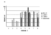
図6は、遠心ファンから生じるnz騒音を示す図で、横軸はnz騒音の周波数であるが回転数を一定として便宜上羽根枚数のZ(Z=1,2,3・・・)で示している。縦軸は騒音値[dB]である。図6において、等ピッチの場合は羽根枚数6枚(Z=6)の場合であり、Z=6にnz騒音が生じる。比較例1、2は等ピッチの場合と同じ羽根枚数6枚(Z=6)で羽根間隔が不等間隔である遠心ファンを等ピッチの場合と同じ回転数で回転させた例である。また比較例1、2は羽根間隔の異なる例である。比較例1、2のように不等間隔の羽根では、Z=6のnz騒音は低減するが、Z=5あるいはZ=7等のZ=6の前後でnz騒音が大きくなる。そして、Z=6より大きい高周波成分(高周波帯)は間隔が狭い羽根において生じる。これに対し、本実施の形態1のように、間隔が最も小さい2つの羽根4_1、4_2の後ろ側にある羽根の反り半径を前側の羽根の反り半径よりも小さくして急激な流速変化を抑えることにより、羽根4_1と羽根4_2の負圧面で生じる剥離を抑制し、遠心ファンの風量低下を抑えつつ、nz騒音の遠心ファンの羽根枚数よりも大きい高周波成分を低減させることが可能となる。
比較例1の不等間隔の遠心ファンにおいて、間隔が最も小さい2つの羽根の後ろ側にある羽根の反り半径を前側の羽根の反り半径よりも小さくした遠心ファンを実施の形態1の遠心ファンとし、図6ではそのnz騒音を示している。本実施の形態1に係る遠心ファンのnz騒音は、破線及び矢印で示すように、Z=6より低周波数側で最も大きな騒音値を示すZ=4の騒音値よりも高周波側であるZ=7及びZ=8の騒音値は小さくなっている。また、比較例1のZ=7及びZ=8における騒音値よりそれぞれ小さく、比較例2のZ=7における騒音値より十分小さく、Z=8における騒音値と同程度まで抑制されていることがわかる。すなわち、本実施の形態1に係る遠心ファンではZ=6より高周波数側におけるトータルの騒音値が比較例1、2より低減している。
以下、実施の形態2に係る遠心ファンについて説明する。
上記実施の形態1においては、不等間隔の羽根を有する遠心ファンにおいて、間隔が狭い羽根が高周波成分を生じることに対し、間隔が最も小さい2つの羽根の後ろ側にある羽根の外周側反り半径を前側の羽根の外周側の反り半径よりも小さくして、後ろ側にある羽根の急激な流速変化を抑えるようにした。本実施の形態2では、図1、4、5で示される、後ろ側にある羽根4_2の出口角度θ2を調整する例について説明する。
θ2<(θ1、θ3、・・・、θZの最小値)
に設定する。このように出口角度を小さくすることで、羽根4の外周から剥離する空気の乱れが小さくなる。これにより、実施の形態1と同様に騒音の高周波成分が低減される効果を奏する。
なお、間隔が最も小さくなる2つの羽根のうち回転方向後ろ側にある羽根4_2の出口角度θ2を、少なくとも前側にある羽根4_1の出口角度θ1より小さくするとよく、したがって0<θ2<θ1となるようにするとよい。その結果、羽根4_2の外周側での急激な流速変化を抑えることができ、騒音の高周波成分低減が可能である。ただし、θが小さくなりすぎると、羽根としての空気を外周に放出させる効果が小さくなって、送風性能が低下することがある。このため、θ2は20°~70°の範囲にあって、θ1よりも5°~15°程度小さな角度であるとよい。
以下、実施の形態3に係る遠心ファンについて説明する。
本実施の形態3においては、不等間隔の羽根を有する遠心ファンにおいて、間隔が狭い羽根が高周波成分を生じることに対し、間隔が最も小さい2つの羽根の後ろ側にある羽根4_2の外径R2を調整する例について説明する。
R2<(R1、R3、・・・、RZの最小値)
に設定する。このように設定することで、回転方向の直前にある羽根4_1で生じた乱流を、後ろ側の羽根4_2が再び乱す現象が抑えられる。その結果、羽根4_2の外周側での急激な流速変化を抑えることができ、騒音の高周波成分低減が可能である。
ただし、他に比べてR2を小さくしすぎると羽根としての空気を外周に放出させる効果が小さくなって、送風性能が低下することがある。このため、図1、4に示されるように間隔が最も小さくなる2つの羽根のうち回転方向後ろ側にある羽根の外径R2は、前側にある羽根の外径R1の90~99%とすると望ましく、95~98%とするとさらによい。
以下、実施の形態4に係る遠心ファンについて説明する。
本実施の形態4においては、不等間隔の羽根を有する遠心ファンにおいて、間隔が狭い羽根が高周波成分を生じることに対し、間隔が最も小さい2つの羽根の後ろ側にある羽根4_2の高さH2を調整する例について説明する。
ただし、他に比べてH2を小さくしすぎると羽根としての空気を外周に放出させる効果が小さくなって、送風性能が低下することがある。このため、間隔が最も小さくなる2つの羽根のうち回転方向後ろ側にある羽根4_2の高さH2は、少なくとも前側にある羽根4_1の高さH1より小さく、高さH1の90~99%とすると望ましく、95~98%とするとさらによい。
以下、実施の形態5に係る遠心ファンについて説明する。
本実施の形態5においては、不等間隔の羽根を有する遠心ファンにおいて、間隔が狭い羽根が高周波成分を生じることに対し、間隔が最も小さい2つの羽根の外周側形状を次の式(1)で規定した。
(4×(θ2/θ1 -1))+0.2×LOG10(S2/S1)
<(P1/(360°/Z)-1) (1)
<(Pm/(360°/Z)-1) (2)
ここで、mは、1、3・・・、Zであり、
例えば、m=1の時、θm=θ1、Sm=S1、Pm=P1
m=3の時、θm=θ3、Sm=S3、Pm=P3
m=Zの時、θm=θZ、Sm=SZ、Pm=PZ
である。
以下、実施の形態6に係る遠心ファンについて説明する。
上記実施の形態1から5においては、不等間隔の羽根を有する遠心ファンにおいて、間隔が狭い羽根が高周波成分を生じることに対し、間隔が最も小さい2つの羽根の特に後ろ側の羽根4_2の外周側形状を規定した。本実施の形態6では、羽根の周方向間隔が羽根間隔の平均値よりも小さい、すなわち、羽根4_Nと羽根4_(N+1)が回転中心Oを挟んでなす角がPN<(360°/Z)の羽根について、次の(3)式を満足するようにしてもよい。
(4×(θ(N+1)/θN -1))
+0.2×LOG10(S(N+1)/SN)
<(PN/(360°/Z) -1) (3)
ここで、Nは、1、2、3・・・、Zであり、Zを超えると1に戻る自然数である。
例えば、N=1の時、
θN=θ1、SN=S1、PN=P1、θ(N+1)=θ2、S(N+1)=S2、
N=2の時、
θN=θ2、SN=S2、PN=P2、θ(N+1)=θ3、S(N+1)=S3、
N=Zの時、
θN=θZ、SN=SZ、PN=PZ、θ(N+1)=θ1、S(N+1)=S1、
である。
以下、実施の形態7に係る遠心ファンについて説明する。
本実施の形態7においては、不等間隔の羽根を有する遠心ファンにおいて、間隔が狭い羽根が高周波成分を生じることに対し、間隔が最も小さい2つの羽根の外周側形状を次の式(4)で規定した。
(4×(θ2/θ1 -1))+(R2/R1 -1)
+(H2/H1 -1 +0.2×LOG10(S2/S1)
<(P1/(360°/Z) -1) (4)
+(H2/Hm -1)+0.2×LOG10(S2/Sm)
<(Pm/(360°/Z) -1) (5)
ここで、mは、1、3・・・、Zであり、
例えば、m=1の時、
θm=θ1、Rm=R1、Hm=H1、Sm=S1、Pm=P1、
m=3の時、
θm=θ3、Rm=R3、Hm=H3、Sm=S3、Pm=P3、
m=Zの時、
θm=θ1、Rm=RZ、Hm=HZ、Sm=SZ、Pm=PZ、
である。
以下、実施の形態8に係る遠心ファンについて説明する。
上記実施の形態7においては、不等間隔の羽根を有する遠心ファンにおいて、間隔が狭い羽根が高周波成分を生じることに対し、間隔が最も小さい2つの羽根の特に後ろ側の羽根4_2の外周側形状を規定した。本実施の形態8では、羽根の周方向間隔が羽根間隔の平均値よりも小さい、すなわち、羽根4_Nと羽根4_(N+1)が回転中心Oを挟んでなす角がPN<(360°/Z)の羽根について次の(6)式を満足するようにしてもよい。
(4×(θ(N+1)/θN -1))+(R(N+1)/RN -1)
+(H(N+1)/HN -1)
+0.2×LOG10(S(N+1)/SN)
<(PN/(360°/Z) -1) (6)
ここで、Nは、1、2、3・・・、Zであり、Zを超えると1に戻る自然数である。
例えば、
N=1の時、
θN=θ1、RN=R1、HN=H1、SN=S1、PN=P1、θ(N+1)=θ2、R(N+1)=R2、HN+1=H2、SN+1=S2、
N=2の時、
θN=θ2、RN=R2、HN=H2、SN=S2、PN=P2、θ(N+1)=θ3、R(N+1)=R3、H(N+1)=H3、S(N+1)=S3、
N=Zの時、
θN=θZ、RN=RZ、HN=HZ、SN=SZ、PN=PZ、θ(N+1)=θ1、R(N+1)=R1、H(N+1)=H1、S(N+1)=S1、
である。
上記実施形態1から実施の形態8の遠心ファンを、交流発電機、モータあるいは駆動装置などの回転電機の回転子に取り付けて利用してもよい。本実施の形態9では一例として、車両用交流発電機に取り付けた例を示す。
図8は上記実施形態1から実施の形態8で開示された遠心ファン1を適用した車両用交流発電機の概略を示した断面図であり。図において、車両用交流発電機は、略椀形状のアルミニウム製のフロント側ハウジング31及びリヤ側ハウジング30からなるケーシング32と、このケーシング32に一対のベアリング33を介して回転自在に支持されたシャフト34と、ケーシング32のフロント側に延出するシャフト34の端部に固着されたプーリ7と、シャフト34と一体的に回転しケーシング32内に配設された回転子8と、回転子8の外周に対向して配置されケーシング32に固定された固定子9と、ケーシング32のリヤ側に延出するシャフト34の延出部に固定され、回転子8に電流を供給する一対のスリップリング10と、各スリップリング10の表面に摺動する一対のブラシ11と、これらのブラシ11を収容しているブラシホルダ17と、これらのブラシ11に隣接されて固定子9で生じた交流電圧の大きさを調整する電圧調整器12と、固定子9で生じる交流電圧を直流電圧に整流する整流装置13と、ヒートシンク18と、電圧調整器12と外部装置(図示せず)との信号の入出力を行うコネクタ20と、ブラシホルダ17と整流装置13を覆うように保護カバー27と、を備えている。
P1/2 -10° < θR < P1/2 +10° (7)
を満たすようにすれば、界磁鉄芯82と遠心ファン1により生じる風音をより効果的に低減することができる。なお、式(7)は概ね爪部の中心が隣り合う2枚の羽根の間隔が最も小さい2枚の羽根の中心から、回転中心に対して±10°の範囲に位置するように配置されることを意味している。このように設定することで、界磁鉄芯82によって生じる急激な速度変化を効果的に抑制することが可能となる。界磁鉄芯82の爪部あるいは遠心ファン1の角度P1を式(7)のように設定することで、実施の形態1から実施の形態8の効果、すなわち、遠心ファン1の風量を維持したまま、騒音の高周波成分を低減することに加え、界磁鉄芯82によって生じる騒音も抑制することができる。
従って、例示されていない無数の変形例が、本願明細書に開示される技術の範囲内において想定される。例えば、少なくとも1つの構成要素を変形する場合、追加する場合または省略する場合、さらには、少なくとも1つの構成要素を抽出し、他の実施の形態の構成要素と組み合わせる場合が含まれるものとする。
Claims (15)
- 回転中心を有する主板と前記主板から前記回転中心を通る回転軸の方向に伸びる複数の羽根とを備えた遠心ファンであって、複数の前記羽根は少なくとも一部に隣り合う羽根の間隔が不等間隔となる配置を含み、前記羽根の長さ方向は前記主板の内周側から外周側に伸びており、前記複数の羽根のうち、回転方向に隣り合う羽根間隔が最も小さくなる間隔の羽根の組において、回転方向後ろ側にある前記羽根と回転方向前側にある前記羽根と前記羽根の外周側の形状が異なり、回転方向後ろ側にある前記羽根は回転方向前側にある前記羽根よりも流体を外周方向に放出させる作用を小さくした遠心ファン。
- 前記複数の羽根のうち、回転方向に隣り合う羽根間隔が最も小さくなる間隔の羽根の組において、前記羽根の内周側から外周側に伸びる第一の部分は、回転方向に対し凹形状に形成され、前記第一の部分から外周側に伸びる第二の部分は、回転方向に対し凸形状に形成されており、回転方向後ろ側にある前記羽根の第二の部分における反り半径が回転方向前側にある前記羽根の第二の部分における反り半径よりも小さい請求項1に記載の遠心ファン。
- 前記複数の羽根の中で、回転方向に隣り合う羽根間隔が最も小さくなる間隔の羽根の組の回転方向後ろ側にある前記羽根の第二の部分における反り半径が最も小さい請求項2に記載の遠心ファン。
- 前記複数の羽根のうち、回転方向に隣り合う羽根間隔が最も小さくなる間隔の羽根の組において、回転方向後ろ側にある前記羽根の出口角度が回転方向前側にある前記羽根の出口角度よりも小さい請求項1から3のいずれか1項に記載の遠心ファン。
- 前記複数の羽根の中で、回転方向に隣り合う羽根間隔が最も小さくなる間隔の羽根の組の回転方向後ろ側にある前記羽根の出口角度が最も小さい請求項4に記載の遠心ファン。
- 前記複数の羽根のうち、回転方向に隣り合う羽根間隔が最も小さくなる間隔の羽根の組において、回転方向後ろ側にある前記羽根の外径が回転方向前側にある前記羽根の外径よりも小さい請求項1から5のいずれか1項に記載の遠心ファン。
- 前記複数の羽根の中で、回転方向に隣り合う羽根間隔が最も小さくなる間隔の羽根の組の回転方向後ろ側にある前記羽根の外径が最も小さい請求項6に記載の遠心ファン。
- 前記複数の羽根のうち、回転方向に隣り合う羽根間隔が最も小さくなる間隔の羽根の組において、回転方向後ろ側にある前記羽根の高さが回転方向前側にある前記羽根の高さよりも小さい請求項1から7のいずれか1項に記載の遠心ファン。
- 前記複数の羽根の中で、回転方向に隣り合う羽根間隔が最も小さくなる間隔の羽根の組の回転方向後ろ側にある前記羽根の高さが最も小さい請求項8に記載の遠心ファン。
- 前記複数の羽根の枚数をZ枚、回転方向に隣り合う羽根間隔が最も小さくなる間隔の羽根の組において、回転方向後ろ側にある前記羽根の第二の部分における反り半径をS2、出口角度をθ2、回転方向前側にある前記羽根の第二の部分における反り半径S1、出口角度をθ1、回転方向後ろ側にある前記羽根と回転方向後ろ側にある前記羽根との最外周端どうしが回転中心を挟んでなす角度をP1とすると、
(4×(θ2/θ1 -1))+0.2×LOG10(S2/S1)
<(P1/(360°/Z) -1)
を満足する請求項2に記載の遠心ファン。 - 前記複数の羽根の枚数をZ枚、回転方向に隣り合う羽根間隔が最も小さくなる間隔の羽根の組において、回転方向後ろ側にある前記羽根の第二の部分における反り半径をS2、出口角度をθ2、羽根の外径をR2、羽根の高さをH2、回転方向前側にある前記羽根の第二の部分における反り半径S1、出口角度をθ1、羽根の外径をR1、羽根の高さをH1、回転方向前側にある前記羽根と回転方向後ろ側にある前記羽根との最外周端どうしが回転中心を挟んでなす角度をP1とすると、
(4×(θ2/θ1 -1))+(R2/R1 -1)
+(H2/H1 -1)+0.2×LOG10(S2/S1)
< (P1/(360°/Z) -1)
を満足する請求項2に記載の遠心ファン。 - 前記複数の羽根の枚数をZ枚、前記羽根の形状を規定する、第二の部分における反り半径をSm、出口角度をθm、羽根の外径をRm、羽根の高さをHm、回転方後ろ側にある前記羽根との最外周端どうしが回転中心を挟んでなす角度をPmとし、
回転方向に隣り合う羽根間隔が最も小さくなる間隔の羽根の組において、回転方向前側にある前記羽根はm=1の第1の羽根であり、回転方向前側にある前記羽根の第二の部分における反り半径をS1、出口角度をθ1、羽根の外径をR1、羽根の高さをH1、回転方前側にある前記羽根と回転方向後ろ側にある前記羽根との最外周端どうしが回転中心を挟んでなす角度をP1とし、
回転方向とは反対方向に順に第Z番目の羽根まで前記羽根の形状を規定するとき、
(4×(θ2/θm -1))+(R2/Rm -1)
+(H2/Hm -1)+0.2×LOG10(S2/Sm)
<(Pm/(360°/Z) -1)
(mは、1、3・・・、Zの自然数)
を満足する請求項2に記載の遠心ファン。 - 回転中心を有する主板と前記主板から前記回転中心を通る回転軸の方向に伸びる枚数をZとする複数の羽根とを備えた遠心ファンであって、複数の前記羽根は少なくとも一部に隣り合う羽根の間隔が不等間隔となる配置を含み、前記羽根の長さ方向は前記主板の内周側から外周側に伸びており、前記複数の羽根のうち、回転方向に隣り合う回転方前側にある前記羽根と回転方向後ろ側にある前記羽根との最外周端どうしが回転中心を挟んでなす角度をPとするとき、P<360°/Z を満たす隣り合う羽根の組において、回転方向後ろ側にある前記羽根と回転方向前側にある前記羽根と前記羽根の外周側の形状が異なり、回転方向後ろ側にある前記羽根は回転方向前側にある前記羽根よりも流体を外周方向に放出させる作用を小さくした遠心ファン。
- 請求項1から13のいずれか1項に記載の遠心ファンが、回転子のフロント側に取り付けられた回転電機。
- 前記回転子は、界磁巻線と、前記界磁巻線を覆うように設けられ複数の爪部を有する界磁鉄芯とを具備し、前記遠心ファンの前記複数の羽根のうち、回転方向に隣り合う羽根間隔が最も小さくなる間隔の羽根の組において、回転方向後ろ側にある前記羽根と回転方向後ろ側にある前記羽根との最外周端どうしが回転中心を挟んでなす角度をP1とすると、前記複数の爪部のうち1つは、回転方向に隣り合う羽根間隔が最も小さくなる間隔の羽根の組の間に配置され、前記回転中心と回転方向の前側の羽根の外周端部とを結ぶ半直線と前記回転中心と前記爪部の中心とを結ぶ半直線とのなす角度をθRとするとき、
P1/2 -10°< θR < P1/2 +10°
を満たす請求項14に記載の回転電機。
Priority Applications (5)
| Application Number | Priority Date | Filing Date | Title |
|---|---|---|---|
| PCT/JP2019/024510 WO2020255334A1 (ja) | 2019-06-20 | 2019-06-20 | 遠心ファンおよび回転電機 |
| JP2019568798A JP6698962B1 (ja) | 2019-06-20 | 2019-06-20 | 遠心ファンおよび回転電機 |
| EP19933808.8A EP3988800B1 (en) | 2019-06-20 | 2019-06-20 | Centrifugal fan and rotary electric machine |
| US17/607,672 US20220220971A1 (en) | 2019-06-20 | 2019-06-20 | Centrifugal fan and rotary electric machine |
| CN201980097449.5A CN114008330B (zh) | 2019-06-20 | 2019-06-20 | 离心风扇和旋转电机 |
Applications Claiming Priority (1)
| Application Number | Priority Date | Filing Date | Title |
|---|---|---|---|
| PCT/JP2019/024510 WO2020255334A1 (ja) | 2019-06-20 | 2019-06-20 | 遠心ファンおよび回転電機 |
Publications (1)
| Publication Number | Publication Date |
|---|---|
| WO2020255334A1 true WO2020255334A1 (ja) | 2020-12-24 |
Family
ID=70776017
Family Applications (1)
| Application Number | Title | Priority Date | Filing Date |
|---|---|---|---|
| PCT/JP2019/024510 Ceased WO2020255334A1 (ja) | 2019-06-20 | 2019-06-20 | 遠心ファンおよび回転電機 |
Country Status (5)
| Country | Link |
|---|---|
| US (1) | US20220220971A1 (ja) |
| EP (1) | EP3988800B1 (ja) |
| JP (1) | JP6698962B1 (ja) |
| CN (1) | CN114008330B (ja) |
| WO (1) | WO2020255334A1 (ja) |
Cited By (2)
| Publication number | Priority date | Publication date | Assignee | Title |
|---|---|---|---|---|
| JP7309302B1 (ja) | 2022-05-13 | 2023-07-18 | 西芝電機株式会社 | 回転電機 |
| JP2023101042A (ja) * | 2022-01-07 | 2023-07-20 | 三菱電機株式会社 | 回転電機 |
Families Citing this family (3)
| Publication number | Priority date | Publication date | Assignee | Title |
|---|---|---|---|---|
| CN110630538A (zh) * | 2018-06-25 | 2019-12-31 | 台达电子工业股份有限公司 | 风扇 |
| JP7123283B1 (ja) * | 2020-12-24 | 2022-08-22 | 三菱電機株式会社 | 遠心ファンおよび遠心ファンを用いた回転電機 |
| US12376660B2 (en) | 2023-01-17 | 2025-08-05 | Sharkninja Operating Llc | Hot brush |
Citations (4)
| Publication number | Priority date | Publication date | Assignee | Title |
|---|---|---|---|---|
| JP2002186215A (ja) * | 2000-10-06 | 2002-06-28 | Hitachi Ltd | 車両用交流発電機 |
| JP2006077631A (ja) | 2004-09-08 | 2006-03-23 | Matsushita Electric Ind Co Ltd | 遠心型送風機の羽根車 |
| JP2011052547A (ja) * | 2009-08-31 | 2011-03-17 | Honda Motor Co Ltd | 遠心式冷却ファンの騒音防止構造 |
| JP2012127217A (ja) * | 2010-12-13 | 2012-07-05 | Mitsubishi Heavy Ind Ltd | 遠心圧縮機の羽根車 |
Family Cites Families (15)
| Publication number | Priority date | Publication date | Assignee | Title |
|---|---|---|---|---|
| US5028826A (en) * | 1989-06-02 | 1991-07-02 | Mitsubishi Denki K.K. | Fan arrangement for a vehicular AC generator |
| US5681145A (en) * | 1996-10-30 | 1997-10-28 | Itt Automotive Electrical Systems, Inc. | Low-noise, high-efficiency fan assembly combining unequal blade spacing angles and unequal blade setting angles |
| JP3871816B2 (ja) * | 1998-09-04 | 2007-01-24 | 三菱電機株式会社 | 車両用交流発電機 |
| JP2001333558A (ja) * | 2000-03-13 | 2001-11-30 | Hitachi Ltd | 車両用交流発電機と冷却ファンの製造方法 |
| FR2811156B1 (fr) * | 2000-06-30 | 2006-12-15 | Valeo Equip Electr Moteur | Ventilateur pour machine electrique tournante, notamment pour alternateur de vehicule automobile |
| JP4211215B2 (ja) * | 2000-10-18 | 2009-01-21 | 株式会社デンソー | 車両用交流発電機 |
| DE10238753B4 (de) * | 2002-08-23 | 2021-11-04 | Seg Automotive Germany Gmbh | Radiallüfterrad zur Förderung von Kühlluft für eine elektrische Maschine |
| FR2850805B1 (fr) * | 2002-12-16 | 2009-01-09 | Valeo Equip Electr Moteur | Dispositif de ventilation pour machine electrique tournante |
| JP4976791B2 (ja) * | 2006-09-08 | 2012-07-18 | 東プレ株式会社 | 遠心ファン用羽根車 |
| US9777742B2 (en) * | 2012-11-06 | 2017-10-03 | Asia Vital Components Co., Ltd. | Centrifugal fan impeller structure |
| JP5930250B2 (ja) * | 2013-03-06 | 2016-06-08 | 三菱電機株式会社 | 回転電機 |
| FR3021171B1 (fr) * | 2014-05-14 | 2020-09-04 | Valeo Equip Electr Moteur | Ventilateur de machine electrique tournante |
| JP2016111894A (ja) * | 2014-12-10 | 2016-06-20 | 株式会社デンソー | 車両用交流発電機 |
| DE102017103984A1 (de) * | 2017-02-27 | 2018-08-30 | Minebea Mitsumi Inc. | Lüfterradanordnung und Verfahren zur Herstellung einer Lüfterradanordnung |
| CN206617363U (zh) * | 2017-03-01 | 2017-11-07 | 讯凯国际股份有限公司 | 叶轮 |
-
2019
- 2019-06-20 CN CN201980097449.5A patent/CN114008330B/zh active Active
- 2019-06-20 WO PCT/JP2019/024510 patent/WO2020255334A1/ja not_active Ceased
- 2019-06-20 EP EP19933808.8A patent/EP3988800B1/en active Active
- 2019-06-20 JP JP2019568798A patent/JP6698962B1/ja active Active
- 2019-06-20 US US17/607,672 patent/US20220220971A1/en not_active Abandoned
Patent Citations (4)
| Publication number | Priority date | Publication date | Assignee | Title |
|---|---|---|---|---|
| JP2002186215A (ja) * | 2000-10-06 | 2002-06-28 | Hitachi Ltd | 車両用交流発電機 |
| JP2006077631A (ja) | 2004-09-08 | 2006-03-23 | Matsushita Electric Ind Co Ltd | 遠心型送風機の羽根車 |
| JP2011052547A (ja) * | 2009-08-31 | 2011-03-17 | Honda Motor Co Ltd | 遠心式冷却ファンの騒音防止構造 |
| JP2012127217A (ja) * | 2010-12-13 | 2012-07-05 | Mitsubishi Heavy Ind Ltd | 遠心圧縮機の羽根車 |
Non-Patent Citations (1)
| Title |
|---|
| See also references of EP3988800A4 |
Cited By (3)
| Publication number | Priority date | Publication date | Assignee | Title |
|---|---|---|---|---|
| JP2023101042A (ja) * | 2022-01-07 | 2023-07-20 | 三菱電機株式会社 | 回転電機 |
| JP7309302B1 (ja) | 2022-05-13 | 2023-07-18 | 西芝電機株式会社 | 回転電機 |
| JP2023167814A (ja) * | 2022-05-13 | 2023-11-24 | 西芝電機株式会社 | 回転電機 |
Also Published As
| Publication number | Publication date |
|---|---|
| EP3988800B1 (en) | 2024-08-07 |
| JP6698962B1 (ja) | 2020-05-27 |
| JPWO2020255334A1 (ja) | 2021-09-13 |
| US20220220971A1 (en) | 2022-07-14 |
| CN114008330B (zh) | 2024-10-11 |
| EP3988800A1 (en) | 2022-04-27 |
| EP3988800A4 (en) | 2022-06-29 |
| CN114008330A (zh) | 2022-02-01 |
Similar Documents
| Publication | Publication Date | Title |
|---|---|---|
| JP6698962B1 (ja) | 遠心ファンおよび回転電機 | |
| CN108302052B (zh) | 直列式轴流风扇 | |
| US6139275A (en) | Impeller for use in cooling dynamoelectric machine | |
| EP2400157B1 (en) | Centrifugal fan | |
| US20180195526A1 (en) | Serial axial flow fan | |
| JPH0795745A (ja) | 回転電機 | |
| JP2661545B2 (ja) | 回転電機 | |
| JP6366851B2 (ja) | 車両用交流発電機 | |
| JP6667745B1 (ja) | 遠心ファンおよび回転電機 | |
| JP6603448B2 (ja) | 遠心インペラ及び遠心ブロワ | |
| JP5652863B2 (ja) | 遠心ファン | |
| JPH09154256A (ja) | 交流発電機 | |
| US7122927B2 (en) | Automotive alternator having cooling-air-intake-window having uneven opening area along rotational direction | |
| JPWO2016189699A1 (ja) | 車両用交流発電機の回転子 | |
| JP4483845B2 (ja) | 車両用交流発電機 | |
| JP7062684B2 (ja) | 遠心ファンおよび回転電機 | |
| JP7123283B1 (ja) | 遠心ファンおよび遠心ファンを用いた回転電機 | |
| JP2018112189A (ja) | 直列式軸流ファン | |
| CN110630536A (zh) | 风扇和电力机械总成及其方法 | |
| WO2021250800A1 (ja) | 遠心ファンおよび回転電機 | |
| JP7416161B2 (ja) | 直列式軸流ファン | |
| JP2021179179A (ja) | 遠心ファンおよび回転電機 | |
| US20220010807A1 (en) | Centrifugal fan and fan blades having integral cooling portion | |
| JP2020186653A (ja) | 軸流ファン | |
| WO2023021597A1 (ja) | 回転電機 |
Legal Events
| Date | Code | Title | Description |
|---|---|---|---|
| ENP | Entry into the national phase |
Ref document number: 2019568798 Country of ref document: JP Kind code of ref document: A |
|
| 121 | Ep: the epo has been informed by wipo that ep was designated in this application |
Ref document number: 19933808 Country of ref document: EP Kind code of ref document: A1 |
|
| NENP | Non-entry into the national phase |
Ref country code: DE |
|
| WWE | Wipo information: entry into national phase |
Ref document number: 2019933808 Country of ref document: EP |
|
| ENP | Entry into the national phase |
Ref document number: 2019933808 Country of ref document: EP Effective date: 20220120 |