WO2020255618A1 - ロータの製造方法およびロータの製造装置 - Google Patents
ロータの製造方法およびロータの製造装置 Download PDFInfo
- Publication number
- WO2020255618A1 WO2020255618A1 PCT/JP2020/020180 JP2020020180W WO2020255618A1 WO 2020255618 A1 WO2020255618 A1 WO 2020255618A1 JP 2020020180 W JP2020020180 W JP 2020020180W WO 2020255618 A1 WO2020255618 A1 WO 2020255618A1
- Authority
- WO
- WIPO (PCT)
- Prior art keywords
- shaft
- pressing member
- core
- rotor
- rotor core
- Prior art date
- Legal status (The legal status is an assumption and is not a legal conclusion. Google has not performed a legal analysis and makes no representation as to the accuracy of the status listed.)
- Ceased
Links
Images












Classifications
-
- H—ELECTRICITY
- H02—GENERATION; CONVERSION OR DISTRIBUTION OF ELECTRIC POWER
- H02K—DYNAMO-ELECTRIC MACHINES
- H02K1/00—Details of the magnetic circuit
- H02K1/06—Details of the magnetic circuit characterised by the shape, form or construction
- H02K1/22—Rotating parts of the magnetic circuit
- H02K1/28—Means for mounting or fastening rotating magnetic parts on to, or to, the rotor structures
-
- H—ELECTRICITY
- H02—GENERATION; CONVERSION OR DISTRIBUTION OF ELECTRIC POWER
- H02K—DYNAMO-ELECTRIC MACHINES
- H02K15/00—Processes or apparatus specially adapted for manufacturing, assembling, maintaining or repairing of dynamo-electric machines
- H02K15/02—Processes or apparatus specially adapted for manufacturing, assembling, maintaining or repairing of dynamo-electric machines of stator or rotor bodies
-
- B—PERFORMING OPERATIONS; TRANSPORTING
- B23—MACHINE TOOLS; METAL-WORKING NOT OTHERWISE PROVIDED FOR
- B23P—METAL-WORKING NOT OTHERWISE PROVIDED FOR; COMBINED OPERATIONS; UNIVERSAL MACHINE TOOLS
- B23P19/00—Machines for simply fitting together or separating metal parts or objects, or metal and non-metal parts, whether or not involving some deformation; Tools or devices therefor so far as not provided for in other classes
- B23P19/02—Machines for simply fitting together or separating metal parts or objects, or metal and non-metal parts, whether or not involving some deformation; Tools or devices therefor so far as not provided for in other classes for connecting objects by press fit or for detaching same
-
- H—ELECTRICITY
- H02—GENERATION; CONVERSION OR DISTRIBUTION OF ELECTRIC POWER
- H02K—DYNAMO-ELECTRIC MACHINES
- H02K15/00—Processes or apparatus specially adapted for manufacturing, assembling, maintaining or repairing of dynamo-electric machines
- H02K15/02—Processes or apparatus specially adapted for manufacturing, assembling, maintaining or repairing of dynamo-electric machines of stator or rotor bodies
- H02K15/028—Fastening stator or rotor bodies to casings, supports, shafts or hubs
-
- Y—GENERAL TAGGING OF NEW TECHNOLOGICAL DEVELOPMENTS; GENERAL TAGGING OF CROSS-SECTIONAL TECHNOLOGIES SPANNING OVER SEVERAL SECTIONS OF THE IPC; TECHNICAL SUBJECTS COVERED BY FORMER USPC CROSS-REFERENCE ART COLLECTIONS [XRACs] AND DIGESTS
- Y02—TECHNOLOGIES OR APPLICATIONS FOR MITIGATION OR ADAPTATION AGAINST CLIMATE CHANGE
- Y02T—CLIMATE CHANGE MITIGATION TECHNOLOGIES RELATED TO TRANSPORTATION
- Y02T10/00—Road transport of goods or passengers
- Y02T10/60—Other road transportation technologies with climate change mitigation effect
- Y02T10/64—Electric machine technologies in electromobility
Definitions
- the present invention relates to a rotor manufacturing method and a rotor manufacturing apparatus.
- Japanese Patent Application Laid-Open No. 2001-268858 discloses a rotor for a motor including a hollow rotating shaft (shaft) having a pipe structure and a laminated iron core (rotor core) into which the rotating shaft is inserted. Further, the rotating shaft is provided with a retaining portion formed by a hydroforming method. The retaining portion is formed by expanding the rotating shaft toward the outer diameter side by the hydroforming method. Further, two retaining portions are provided on one side and the other side in the axial direction of the laminated iron core so as to sandwich the laminated iron core in the axial direction. As a result, the laminated iron core and the rotating shaft are fixed (positioned) in the axial direction by the two retaining portions.
- hydroforming is performed in a state where a molding die (die) for hydroforming is arranged at a position separated by a predetermined distance from the end face of the laminated iron core (rotor core).
- a molding die (die) for hydroforming is arranged at a position separated by a predetermined distance from the end face of the laminated iron core (rotor core).
- the rotation axis between the end face of the laminated iron core and the molding die (die) expands to the outer diameter side, and a retaining portion is formed.
- the rotating shaft is fixed by molding dies (dies) on both sides in the axial direction.
- the laminated iron core (rotor core) is located at a position separated from the hydroforming mold (die) during hydroforming. Since it is provided in, hydroforming is performed with no load on the end face of the laminated iron core.
- the product thickness of the laminated steel cores may vary between products (between motor rotors) due to the formation of gaps between the plurality of electromagnetic steel plates constituting the laminated steel cores. Therefore, there is a disadvantage that the position of the end face of the laminated iron core in the axial direction varies. In this case, there is a problem that the relative positional relationship between the rotating shaft (shaft) and the laminated iron core (rotor core) varies.
- the present invention has been made to solve the above problems, and one object of the present invention is to prevent variations in the relative positional relationship between the shaft and the rotor core. It is to provide a rotor manufacturing method and a rotor manufacturing apparatus.
- the method for manufacturing a rotor according to the first aspect of the present invention is a method for manufacturing a rotor including an annular rotor core having a shaft insertion hole and a tubular shaft, the rotor core.
- This comprises a step of fixing the shaft to the rotor core by hydroforming in which the shaft is brought into pressure contact with the inner peripheral surface of the shaft insertion hole by expanding the shaft.
- hydroforming can be performed in a state where the rotor core is pressed by the core pressing member as described above.
- hydroforming can be performed in a state where the core pressing member prevents a gap from being generated between the electromagnetic steel sheets constituting the rotor core.
- hydroforming can be performed with the product thickness of the rotor core within a certain range (within the tolerance range). As a result, it is possible to prevent variations in the relative positional relationship between the shaft and the rotor core (between products).
- the rotor manufacturing apparatus is a rotor manufacturing apparatus including an annular rotor core having a shaft insertion hole and a tubular shaft, and presses the rotor core in the direction of the central axis of the rotor core.
- the shaft With the mold pressing part including the core pressing member and the rotor core pressed, the shaft is filled with fluid and the shaft is expanded by pressurizing the fluid, so that the shaft is formed on the inner peripheral surface of the shaft insertion hole. It is provided with a hydroforming unit for performing hydroforming to press-contact.
- hydroforming can be performed in a state where the rotor core is pressed by the core pressing member as described above. As a result, hydroforming can be performed in a state where the core pressing member prevents a gap from being generated between the electromagnetic steel sheets constituting the rotor core. As a result, hydroforming can be performed with the product thickness of the rotor core within a certain range (within the tolerance range). As a result, it is possible to provide a rotor manufacturing apparatus capable of preventing variations in the relative positional relationship between the shaft and the rotor core (between products).
- FIG. 5 is a cross-sectional view of a state in which the rotor core according to the first embodiment is arranged on a fixed base.
- FIG. 5 is a cross-sectional view of a state in which the core pressing member according to the first embodiment is in contact with the rotor core.
- FIG. 5 is a cross-sectional view of a state in which the shaft pressing member according to the first embodiment is in contact with a stepped portion of the shaft.
- FIG. 5 is a cross-sectional view of a state in which the upper seal member according to the first embodiment is in contact with the shaft pressing member.
- FIG. 5 is a cross-sectional view of a state in which the shaft according to the first embodiment is in contact with a fixed base. It is a figure which showed the relationship between the pressing force to the end face of a rotor core, and the product thickness of a rotor core.
- FIG. 5 is a cross-sectional view of a state in which the rotor core according to the second embodiment is arranged on a fixed base.
- FIG. 5 is a cross-sectional view of a state in which the core pressing member according to the second embodiment is in contact with the rotor core.
- FIG. 5 is a cross-sectional view of a state in which the shaft pressing member according to the second embodiment is in contact with a stepped portion of the shaft.
- FIG. 5 is a cross-sectional view of a state in which the upper seal member according to the second embodiment is in contact with the shaft pressing member.
- FIG. 5 is a cross-sectional view of a state in which the shaft according to the second embodiment is in contact with a fixed base. It is sectional drawing of the state in which the fluid is introduced into the shaft by 2nd Embodiment. It is sectional drawing of the rotor manufacturing apparatus according to 3rd Embodiment. It is a top view of the shaft pressing member according to 3rd Embodiment.
- FIG. 5 is a cross-sectional view of a state in which the rotor core according to the third embodiment is arranged on a fixed base.
- FIG. 5 is a cross-sectional view of a state in which the shaft pressing member according to the third embodiment is in contact with a stepped portion of the shaft.
- FIG. 5 is a cross-sectional view of a state in which the core pressing member according to the third embodiment is in contact with the rotor core.
- FIG. 5 is a cross-sectional view of a state in which the shaft according to the third embodiment is in contact with a fixed base. It is sectional drawing of the state in which the fluid is introduced into the shaft according to 3rd Embodiment.
- the "axial direction” means a direction (see FIG. 1) along the rotation axis (reference numeral O) (Z1 direction, Z2 direction) of the rotor 10.
- the “circumferential direction” means the circumferential direction (A direction, A1 direction, A2 direction) of the rotor core 11.
- the “diameter inside” means a direction (B1 direction) toward the center of the rotor core 11.
- the “diameter outside” means a direction (B2 direction) toward the outside of the rotor core 11.
- the rotary electric machine 100 includes a rotor 10 and a stator 20.
- the stator 20 includes an annular stator core 21.
- the stator core 21 is provided with a plurality of slots 22.
- a segment conductor 30 is arranged in each of the plurality of slots 22.
- the stator core 21 includes a back yoke 23 that connects the radial outer side of the slot 22 in an annular shape, and a plurality of teeth 24 that are provided between adjacent slots 22 and extend radially inward from the back yoke 23.
- an insulating member (not shown) for insulating the segment conductor 30 and the stator core 21 is arranged.
- the rotor 10 includes a rotor core 11 having a ring shape.
- the rotor core 11 is formed by laminating a plurality of electromagnetic steel plates 12 (see FIG. 2). Further, the rotor core 11 is arranged so as to face the stator core 21 in the radial direction inside the annular stator core 21 in the radial direction. That is, the rotary electric machine 100 is an inner rotor type rotary electric machine. Further, the rotor core 11 includes a shaft insertion hole 110 into which a shaft 13 described later is inserted.
- the rotor 10 includes a shaft 13.
- the shaft 13 functions as a rotation shaft of the rotor core 11. Further, the shaft 13 has a tubular shape. That is, the shaft 13 has a hollow shape and is formed so as to extend in the axial direction (Z direction).
- the shaft 13 has a tubular portion 130 which is a portion fixed to the inner peripheral surface 110a of the shaft insertion hole 110 of the rotor core 11 and a rotor core 11 rather than the tubular portion 130.
- the tubular portion 131 provided on one side (Z1 direction side) in the central axis direction is included.
- the tubular portion 131 projects from the end surface 11a on one side (Z1 direction side) of the rotor core 11 in the central axis direction to one side (Z1 direction side) in the central axis direction.
- the stepped portion 133 of the shaft 13, which will be described later, is arranged on one side (Z1 direction side) in the central axis direction with respect to the end surface 11a of the rotor core 11.
- the tubular portion 130 and the tubular portion 131 are examples of the "first tubular portion” and the "second tubular portion” in the claims, respectively.
- the tubular portion 130 has a diameter r1.
- the second tubular portion has a diameter r2 smaller than the diameter r1 of the tubular portion 130.
- the diameter r1 is the diameter of the outer peripheral surface 130a of the tubular portion 130 (the outer diameter of the tubular portion 130).
- the diameter r2 is the diameter of the outer peripheral surface 131a of the tubular portion 131 (the outer diameter of the tubular portion 131).
- the shaft 13 includes a tubular portion 132 provided on the other side (Z2 direction side) of the rotor core 11 in the central axis direction than the tubular portion 130.
- the tubular portion 132 projects from the end surface 11b on the other side (Z2 direction side) of the rotor core 11 in the central axis direction to the other side (Z2 direction side) in the central axis direction.
- the stepped portion 134 of the shaft 13, which will be described later, is arranged on the other side (Z2 direction side) of the end surface 11b in the central axis direction.
- the tubular portion 132 has a diameter r3 having a size substantially equal to the diameter r2 of the second tubular portion.
- the diameter r3 is the diameter of the outer peripheral surface 132a of the tubular portion 132 (the outer diameter of the tubular portion 132).
- the shaft 13 includes a stepped portion 133 which is a boundary portion between the tubular portion 130 and the tubular portion 131.
- the step portion 133 has an annular shape (see FIG. 1) when viewed from the central axis direction (Z1 direction side).
- the step portion 133 is provided as a bearing arrangement portion in which the bearing portion 14 of the shaft 13 is arranged.
- the shaft 13 includes a stepped portion 134 which is a boundary portion between the tubular portion 130 and the tubular portion 132.
- the step portion 134 has a ring shape like the step portion 133 when viewed from the central axis direction (Z2 direction side).
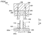
- the manufacturing apparatus 200 of the rotor 10 includes a mold 200a for hydroforming.
- the mold 200a for hydroforming has a mold pressing portion 200b.
- the rotor 10 manufacturing apparatus 200 (200a, 200b) includes a shaft pressing member 201 and a core pressing member 202.
- the shaft pressing member 201 is configured to press the step portion 133, which will be described later, from one side (Z1 direction side) in the central axis direction.
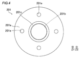
- the shaft pressing member 201 includes a shaft pressing member main body 201a having an annular shape (see FIG. 4).
- a through hole 201b is provided at the center of the shaft pressing member main body 201a.
- the shaft pressing member 201 is provided so as to overlap the core pressing member main body 202a described later when viewed from the central axis direction.
- the shaft pressing member 201 includes a tubular pressing portion 201c provided on the inner peripheral side of the shaft pressing member main body portion 201a.
- the tubular pressing portion 201c is provided so as to extend from the shaft pressing member main body portion 201a toward the other side (Z2 direction side) in the central axis direction.
- the tubular pressing portion 201c is provided along the outer peripheral edge of the through hole 201b of the shaft pressing member main body portion 201a when viewed from the central axis direction (Z2 direction side) (see FIG. 4).
- the shaft 13 in the tubular pressing portion 201c, is in a state where the end portion 201d on the other side (Z2 direction side) of the tubular pressing portion 201c in the central axis direction is in contact with the step portion 133. It is provided so as to guide the tubular portion 131 of the above from the outer peripheral side.
- the tubular portion 131 of the shaft 13 and the upper side of the core pressing member main body portion 202a will be described later, in a state where the end portion 201d of the tubular pressing portion 201c is in contact with the step portion 133. It is arranged so as to be sandwiched between the portion 202d and the portion 202d.
- the shaft pressing member main body 201a is provided with a plurality of through holes 201e (four in the first embodiment, see FIG. 4) through which the core pressing member side shaft 202f, which will be described later, penetrates.
- the plurality of through holes 201e are provided at equal angular intervals around the through holes 201b.
- the number of the core pressing member side shaft 202f and the through hole 201e is not limited to four, and may be, for example, two or three.
- the shaft pressing member 201 is independent of the core pressing member side shaft 202f between the hydraulic cylinder 208 and the core pressing member main body 202a, which will be described later, in a state where the core pressing member side shaft 202f is penetrated through the through hole 201e. It is configured to be movable. That is, the shaft pressing member 201 is configured to slide along the core pressing member side shaft 202f in a state where the core pressing member side shaft 202f penetrates through the through hole 201e.
- the core pressing member 202 is configured to press the end surface 11a of the rotor core 11 from one side (Z1 direction side) in the central axis direction. Further, the core pressing member 202 is configured to be operable independently of the shaft pressing member 201.
- the core pressing member 202 includes a core pressing member main body portion 202a that comes into contact with the end surface 11a of the rotor core 11.
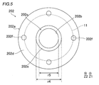
- the core pressing member main body 202a has an annular shape (see FIG. 5). Specifically, a through hole 202b is provided in the center of the core pressing member main body portion 202a.
- the core pressing member main body portion 202a is provided with a step portion 202c.
- the core pressing member main body portion 202a is provided on one side (Z1 direction side) of the step portion 202c in the central axis direction and on the other side (Z2 direction side) of the step portion 202c in the central axis direction.
- the lower portion 202e includes the lower portion 202e to be
- the diameter r4 (see FIG. 5) of the portion of the through hole 202b of the core pressing member 202 corresponding to the upper portion 202d is the portion of the through hole 202b of the core pressing member 202 corresponding to the lower portion 202e. It is larger than the diameter r5 (see FIG. 5).
- the upper portion 202d of the core pressing member 202 is provided so as to guide the tubular pressing portion 201c of the shaft pressing member 201 from the outer peripheral side.
- the lower portion 202e is provided so as to guide the vicinity of one end (the end portion on the Z1 direction side) of the tubular portion 130 of the shaft 13 in the central axis direction from the outer peripheral side.
- the core pressing member 202 includes a core pressing member side shaft 202f extending from the core pressing member main body portion 202a to one side (Z1 direction side) in the central axis direction.
- the core pressing member side shaft 202f is provided in the same number (that is, four) as the through holes 201e of the shaft pressing member main body portion 201a.
- Each of the plurality of core pressing member side shafts 202f is provided so as to penetrate the corresponding through hole 201e.
- the manufacturing apparatus 200 (mold 200a) of the rotor 10 includes a fixing base 203 including a shaft fixing portion 203a and a rotor core fixing portion 203b.
- the shaft fixing portion 203a is integrally formed with the rotor core fixing portion 203b.
- the shaft fixing portion 203a is arranged on the other side (Z2 direction side) of the shaft 13 in the central axis direction.
- the shaft fixing portion 203a is provided so as to fix the shaft 13 from the other side (Z2 direction side) in the central axis direction.
- the shaft fixing portion 203a is arranged so as to fix (hold) the stepped portion 134 of the shaft 13.
- the fixing base 203 is provided with a stepped portion 203c provided at a boundary portion between the shaft fixing portion 203a and the rotor core fixing portion 203b on which the stepped portion 134 of the shaft 13 is placed.
- the rotor core fixing portion 203b is arranged on the other side (Z2 direction side) of the core pressing member 202 (rotor core 11) in the central axis direction.
- the rotor core fixing portion 203b is provided so as to fix the rotor core 11 from the other side (Z2 direction side) in the central axis direction.
- the rotor core 11 is fixed (held) by being placed on the end surface 203d on one side (Z1 direction side) of the rotor core fixing portion 203b in the central axis direction.
- the manufacturing apparatus 200 (mold 200a) of the rotor 10 includes a hydroforming unit 204 for performing hydroforming.
- the hydroforming portion 204 includes an upper seal member 204a and a lower seal member 204b.
- the opening 135 on one side (Z1 direction side) of the shaft 13 in the central axis direction is closed by the upper sealing member 204a, and the opening 136 on the other side (Z2 direction side) of the shaft 13 in the central axis direction is closed.
- the inside of the shaft 13 is filled with the fluid 40 (see FIG. 14) by the fluid introduction path (not shown) provided in the upper seal member 204a or the lower seal member 204b while being closed by the lower seal member 204b. Will be done.
- the tubular portion 130 is pressed against the inner peripheral surface 110a (see FIG. 2) of the shaft insertion hole 110. Will be done.
- the upper seal member 204a has an upper pedestal portion 204c provided on one side in the central axis direction, and an upper pillar portion 204d extending from the upper pedestal portion 204c to the other side (Z2 direction side) in the central axis direction.
- the upper pillar portion 204d is provided so as to be inserted into the through hole 201b of the shaft pressing member 201. That is, the upper seal member 204a (upper pillar portion 204d) is provided so as to close the opening 135 of the shaft 13 inside the through hole 201b of the shaft pressing member 201.
- the lower seal member 204b includes a lower pedestal portion 204e provided on the other side in the central axis direction and a lower pillar portion 204f extending from the lower pedestal portion 204e to one side (Z1 direction side) in the central axis direction.
- the lower pillar portion 204f is provided so as to be inserted into the through hole 203e provided in the fixing base 203. That is, the lower seal member 204b (lower pillar portion 204f) is provided so as to close the opening 136 of the shaft 13 inside the through hole 203e of the fixing base 203.
- the rotor 10 manufacturing apparatus 200 includes a plate portion 205 provided so as to be sandwiched between the moving mechanism portion 207 and the upper seal member 204a (upper pedestal portion 204c) described later.
- the plate portion 205 has a disk shape (see FIG. 6).
- the plate portion 205 is provided with a through hole 205a for penetrating the rod portion 208b of the hydraulic cylinder 208 and the core pressing member side shaft 202f, which will be described later. That is, the number of through holes 205a is the same as that of the core pressing member side shaft 202f (four in the first embodiment).
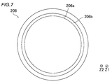
- the rotor 10 manufacturing apparatus 200 (mold 200a) is provided along the outer peripheral edge of the plate portion 205, and has a guide portion 206 extending from the plate portion 205 toward the other side (Z2 direction side) in the central axis direction. Including. That is, the guide portion 206 has an annular shape (see FIG. 7).
- the shaft pressing member 201 (shaft pressing member main body portion 201a) is configured to slide along the inner peripheral surface 206a of the guide portion 206.
- the guide portion 206 includes a protruding portion 206b provided at the end of the guide portion 206 on the other side (Z2 direction side) in the central axis direction and protruding toward the inner peripheral side from the inner peripheral surface 206a. ..
- the protruding portion 206b has an annular shape (see FIG. 7).
- the manufacturing apparatus 200 of the rotor 10 includes a moving mechanism unit 207.
- the moving mechanism unit 207 is configured to be movable along the central axis direction on one side (Z1 direction side) of the rotor core 11 in the central axis direction. Further, the moving mechanism unit 207 is configured to integrally move the shaft pressing member 201 and the core pressing member 202 toward the rotor core 11 side (Z2 direction side).
- the rotor 10 manufacturing apparatus 200 includes a hydraulic cylinder 208 provided between the moving mechanism portion 207 and the core pressing member 202 (see FIG. 8).
- the hydraulic cylinder 208 is configured to be driven by the flood pressure from the outside of the moving mechanism unit 207. That is, the hydraulic cylinder 208 is configured to be expandable and contractible along the central axis direction by moving the rod portion 208b in the central axis direction by the pressure of the fluid flowing into the cylinder tube 208a.
- the cylinder tube 208a is provided inside the moving mechanism portion 207.
- a plurality (that is, four) hydraulic cylinders 208 are provided so as to correspond to each of the plurality of core pressing member side shafts 202f of the core pressing member 202.
- the hydraulic cylinder 208 is an example of the "first cylinder" and the "expandable member” in the claims.
- the hydraulic cylinder 208 is the end portion 202g and the central axis of the core pressing member side shaft 202f protruding from the through hole 201e of the shaft pressing member 201 to one side (Z1 direction side) in the central axis direction. They are provided so as to be adjacent to each other along the direction. Specifically, the tip of the rod portion 208b of the hydraulic cylinder 208 is in contact with the end portion 202g on one side (Z1 direction side) of the core pressing member side shaft 202f in the central axis direction.
- the moving mechanism portion 207 is configured to press the step portion 133 via the shaft pressing member 201.
- the hydraulic cylinder 208 is configured to press the end surface 11a of the rotor core 11 via the core pressing member 202. That is, a pressing force independent (no correlation) from the pressing force by the moving mechanism portion 207 is applied to the end surface 11a of the rotor core 11 by the hydraulic cylinder 208 via the core pressing member 202.
- the rotor core 11 is placed on the fixing base 203 (rotor core fixing portion 203b). As a result, the rotor core 11 is fixed from the other side (Z2 direction side) in the central axis direction.
- the opening 136 on the other side (Z2 direction side) of the shaft 13 in the central axis direction is closed by the lower seal member 204b.
- the stepped portion 133 of the shaft 13 is pressed by the shaft pressing member 201 from one side (Z1 direction side) in the central axis direction, and the shaft is pressed.
- a step of pressing the end surface 11a of the rotor core 11 from one side (Z1 direction side) in the central axis direction is performed by the core pressing member 202 that can operate independently of the member 201.
- the moving mechanism unit 207 integrally moves the shaft pressing member 201 and the core pressing member 202 to the rotor core 11 side (Z2 direction side).
- the shaft pressing member 201 and the core pressing member 202 are integrally on the rotor core 11 side (Z2 direction) until the core pressing member 202 abuts on the end surface 11a of the rotor core 11 by the moving mechanism portion 207. Moved to the side). As a result, the core pressing member 202 (core pressing member main body portion 202a) is brought into contact with the end surface 11a of the rotor core 11.
- the shaft pressing member 201 is further moved to the rotor core 11 side (Z2 direction side) by the moving mechanism portion 207, so that the shaft pressing member 201 hits the step portion 133 of the shaft 13. Be touched.
- the rod portion 208b of the hydraulic cylinder 208 is pushed into the cylinder tube 208a by the core pressing member 202 (core pressing member side shaft 202f), so that the hydraulic cylinder 208 is contracted.
- the moving mechanism portion 207 moves the upper seal member 204a until it comes into contact with the shaft pressing member 201 (shaft pressing member main body portion 201a).
- the guide portion 206 is moved to the other side in the central axis direction by the moving mechanism portion 207, so that the shaft pressing member 201 (shaft pressing member main body portion 201a) is moved along the inner peripheral surface 206a of the guide portion 206. It is slid.
- the rod portion 208b of the hydraulic cylinder 208 is pushed into the cylinder tube 208a by the core pressing member 202 (core pressing member side shaft 202f), so that the hydraulic cylinder 208 is further (compared to the state of FIG. 10). It can be shrunk.
- the opening 135 on one side (Z1 direction side) of the shaft 13 in the central axis direction is closed by the upper seal member 204a.
- the upper seal member 204a, the shaft pressing member 201, and the shaft 13 are moved by the moving mechanism portion 207 until the step portion 134 of the shaft 13 abuts on the step portion 203c of the fixing base 203. It is integrally moved to the other side (Z2 direction side) in the central axis direction.
- the rod portion 208b of the hydraulic cylinder 208 is pushed into the cylinder tube 208a by the core pressing member 202 (core pressing member side shaft 202f), so that the hydraulic cylinder 208 is further (compared to the state of FIG. 11). It can be shrunk.
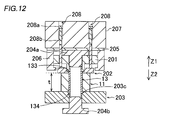
- the stepped portion 133 of the shaft 13 is pressed by the moving mechanism portion 207 via the shaft pressing member 201, and the end surface 11a of the rotor core 11 is pressed via the core pressing member 202 by the pressing force of the hydraulic cylinder 208. Will be done.
- the step portion 133 is pressed by the shaft pressing member 201 from one side (Z1 direction side) in the central axis direction, and is pressed by the core pressing member 202.
- the step portion 133 is pressed by the shaft pressing member 201 to press the shaft 13 against the shaft fixing portion 203a (fixing base 203), and the core pressing member 202.
- the gap between the electromagnetic steel sheets 12 is reduced by pressing the end face 11a of the rotor core 11 while being fixed to the rotor core fixing portion 203b (fixing base 203). Compresses by a predetermined amount. That is, the product thickness t (see FIG. 12) of the rotor core 11 changes depending on the pressing force applied to the end face 11a. Specifically, the larger the pressing force on the end face 11a, the smaller the product thickness t of the rotor core 11.
- the rate of change of the product thickness t with respect to the pressing force becomes equal to or less than a predetermined value (to the extent that there is almost no change).
- the shaft 13 to the shaft fixing portion 203a (fixing base 203), the position in the central axis direction is uniquely determined. As a result, the shaft 13 and the rotor core 11 are relatively positioned by adjusting the pressing force applied to the end surface 11a of the rotor core 11.
- pressing the end surface 11a of the rotor core 11 via the core pressing member 202 by the pressing force of the hydraulic cylinder 208 drives the hydraulic cylinder 208 by the oil pressure from the outside of the moving mechanism portion 207. This is to press the end surface 11a of the rotor core 11 via the core pressing member 202. That is, only the pressing force by the hydraulic cylinder 208 controlled by the flood control, which is independent of the pressing force by the moving mechanism unit 207, is applied to the end surface 11a of the rotor core 11.
- pressing the step portion 133 of the shaft 13 by the shaft pressing member 201 means pressing the step portion 133 as the bearing arrangement portion on which the bearing portion 14 of the shaft 13 is arranged by the shaft pressing member 201. That is, the bearing arrangement portion in which the bearing portion 14 is arranged is diverted as the step portion 133 for pressing the shaft 13.
- pressing the rotor core 11 means pressing the entire surface of the end surface 11a of the rotor core 11 by the core pressing member 202. That is, as shown in FIG. 5, the core pressing member 202 is arranged so as to cover the entire end surface 11a (see FIG. 3) of the rotor core 11 when viewed from the central axis direction.
- pressing the shaft 13 means pressing the stepped portion 133 of the shaft 13 by the shaft pressing member 201 over the entire circumference of the shaft 13. That is, the stepped portion 133 (see FIG. 1) of the shaft 13 provided in an annular shape is pressed by the shaft pressing member 201 (cylindrical pressing portion 201c) (see FIG. 4) provided in an annular shape. ..
- the shaft 13 in a state where the shaft 13 and the rotor core 11 are pressed, the shaft 13 is expanded by filling the inside of the shaft 13 with the fluid 40 and pressurizing the fluid 40.
- the shaft 13 is fixed to the rotor core 11 by hydroforming in which the tubular portion 130 is pressed against the inner peripheral surface 110a of the shaft insertion hole 110. That is, the shaft 13 is fixed to the rotor core 11 by hydroforming while the shaft 13 and the rotor core 11 are relatively positioned.
- the manufacturing apparatus 300 of the rotor 10 includes a mold 300a for hydroforming.
- the mold 300a for hydroforming has a mold pressing portion 200b.
- the rotor 10 manufacturing apparatus 300 (300a, 200b) includes a shaft pressing member 201 and a core pressing member 202.
- the manufacturing apparatus 300 (mold 300a) of the rotor 10 is provided with a hydroforming unit 304 for performing hydroforming.
- the hydroforming portion 304 includes an upper seal member 304a and a lower seal member 204b.
- the opening 135 on one side (Z1 direction side) of the shaft 13 in the central axis direction is closed by the upper seal member 304a, and the opening 136 on the other side (Z2 direction side) of the shaft 13 in the central axis direction is closed.
- the fluid 40 is filled inside the shaft 13 by a fluid introduction path (not shown) provided in the upper seal member 304a or the lower seal member 204b in a state of being closed by the lower seal member 204b.
- the tubular portion 130 is pressed against the inner peripheral surface 110a (see FIG. 2) of the shaft insertion hole 110. Will be done.
- the upper seal member 304a has an upper pedestal portion 304c provided on one side in the central axis direction, and an upper pillar portion 304d extending from the upper pedestal portion 304c to the other side (Z2 direction side) in the central axis direction.
- the upper pillar portion 304d is provided so as to be inserted into the through hole 201b of the shaft pressing member 201. That is, the upper seal member 304a (upper pillar portion 304d) is provided so as to close the opening 135 of the shaft 13 inside the through hole 201b of the shaft pressing member 201.
- the rotor 10 manufacturing apparatus 300 (mold 300a) includes a plate portion 305 provided so as to be sandwiched between the moving mechanism portion 307 and the upper seal member 304a (upper pedestal portion 304c) described later.
- the plate portion 305 has a disk shape (see FIG. 16).
- the rotor 10 manufacturing apparatus 300 (mold 300a) is provided along the outer peripheral edge of the plate portion 305, and has a guide portion 306 extending from the plate portion 305 toward the other side (Z2 direction side) in the central axis direction. Including. That is, the guide portion 306 has an annular shape (see FIG. 17).
- the shaft pressing member 201 (shaft pressing member main body portion 201a) is configured to slide along the inner peripheral surface 306a of the guide portion 306.
- the guide portion 306 includes a protruding portion 306b provided at the other end portion of the guide portion 306 in the direction of the central axis and protruding toward the inner peripheral side from the inner peripheral surface 306a.
- the protruding portion 306b has an annular shape (see FIG. 17).
- the manufacturing apparatus 300 of the rotor 10 includes a moving mechanism unit 307.
- the moving mechanism unit 307 is configured to be movable along the central axis direction on one side (Z1 direction side) of the rotor core 11 in the central axis direction.
- the manufacturing apparatus 300 of the rotor 10 includes an air cylinder 308 provided between the moving mechanism portion 307 and the core pressing member 202.
- the air cylinder 308 is sandwiched between the moving mechanism portion 307 and the core pressing member 202.
- the air cylinder 308 moves to the core pressing member 202 (core pressing member side shaft 202f) side (Z2 direction side) with the core pressing member 202 (core pressing member side shaft 202f) fixed, so that the rod portion 308b Is pushed into the cylinder tube 308a.
- the pressure inside the cylinder tube 308a of the air cylinder 308 changes, so that the pressing force applied from the air cylinder 308 to the end surface 11a of the rotor core 11 via the core pressing member 202 changes.
- a plurality (that is, four) air cylinders 308 are provided so as to correspond to each of the plurality of core pressing member side shafts 202f of the core pressing member 202.
- the air cylinder 308 is an example of the "second cylinder" and the "expandable member" in the claims.
- the air cylinder 308 is along the central axis direction with the end portion 202g of the core pressing member side shaft 202f projecting from the through hole 201e of the shaft pressing member 201 to one side (Z1 direction side) in the central axis direction. It is provided so as to be adjacent to each other. Specifically, the tip of the rod portion 308b of the air cylinder 308 is in contact with the end portion 202g on one side (Z1 direction side) of the core pressing member side shaft 202f in the central axis direction.
- the moving mechanism portion 307 is configured to press the step portion 133 via the shaft pressing member 201.
- the air cylinder 308 is configured to press the end surface 11a of the rotor core 11 via the core pressing member 202. That is, a pressing force independent (no correlation) of the pressing force by the moving mechanism portion 307 is applied to the end surface 11a of the rotor core 11 by the air cylinder 308 via the core pressing member 202.
- the rotor core 11 is placed on the fixing base 203 (rotor core fixing portion 203b). As a result, the rotor core 11 is fixed from the other side (Z2 direction side) in the central axis direction.
- the opening 136 on the other side (Z2 direction side) of the shaft 13 in the central axis direction is closed by the lower seal member 204b.
- the shaft pressing member 201 and the core pressing member 202 are integrally on the rotor core 11 side (Z2) until the core pressing member 202 abuts on the end surface 11a of the rotor core 11 by the moving mechanism portion 307. Moved to the direction side).
- the core pressing member 202 core pressing member main body portion 202a
- the core pressing member main body portion 202a is brought into contact with the end surface 11a of the rotor core 11.
- the shaft pressing member 201 is further moved to the rotor core 11 side (Z2 direction side) by the moving mechanism portion 307, so that the shaft pressing member 201 hits the stepped portion 133 of the shaft 13. Be touched.
- the rod portion 308b of the air cylinder 308 is pushed into the cylinder tube 308a by the core pressing member 202 (core pressing member side shaft 202f), so that the air cylinder 308 is contracted.
- the moving mechanism portion 307 moves the upper seal member 304a until it comes into contact with the shaft pressing member 201 (shaft pressing member main body portion 201a).
- the guide portion 306 is moved to the other side (Z2 direction side) in the central axis direction by the moving mechanism portion 307, so that the shaft pressing member 201 (shaft pressing member main body portion 201a) is moved to the inner circumference of the guide portion 306. It is slid along the surface 306a.
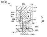
- the rod portion 308b of the air cylinder 308 is pushed into the cylinder tube 308a by the core pressing member 202 (core pressing member side shaft 202f), so that the air cylinder 308 is further (compared to the state of FIG. 20). It can be shrunk.
- the opening 135 on one side (Z1 direction side) of the shaft 13 in the central axis direction is closed by the upper seal member 304a.
- the upper seal member 304a, the shaft pressing member 201, and the shaft 13 are moved by the moving mechanism portion 307 until the step portion 134 of the shaft 13 abuts on the step portion 203c of the fixing base 203. It is integrally moved to the other side (Z2 direction side) in the central axis direction.
- the rod portion 308b of the air cylinder 308 is pushed into the cylinder tube 308a by the core pressing member 202 (core pressing member side shaft 202f), so that the air cylinder 308 is further (compared to the state of FIG. 21). It can be shrunk.
- the pressing force of the air cylinder 308 is a force that presses the rod portion 308b by the pressure of the air inside the cylinder tube 308a of the air cylinder 308 in the contracted state.
- the method for manufacturing the rotor 10 according to the third embodiment and the manufacturing apparatus 400 for the rotor 10 will be described with reference to FIGS. 2 and 24 to 33.
- the spring member 408 is used unlike the first embodiment in which the cylinder (hydraulic cylinder 208) is used.
- the same configuration as that of the first embodiment is illustrated with the same reference numerals as those of the first embodiment, and the description thereof will be omitted.
- the manufacturing apparatus 400 of the rotor 10 includes a mold 400a for hydroforming.
- the mold 400a for hydroforming has a mold pressing portion 400b.
- the rotor 10 manufacturing apparatus 400 (400a, 400b) includes a shaft pressing member 401 and a core pressing member 402.
- the shaft pressing member 401 is configured to press the stepped portion 133 of the shaft 13 from one side (Z1 direction side) in the central axis direction.
- the shaft pressing member 401 includes a shaft pressing member main body 401a having an annular shape (see FIG. 25).
- a through hole 401b is provided at the center of the shaft pressing member main body 401a.
- the shaft pressing member 401 is provided so as to overlap the core pressing member 402 when viewed from the central axis direction.
- the shaft pressing member 401 includes a tubular pressing portion 401c provided on the inner peripheral side of the shaft pressing member main body portion 401a.
- the tubular pressing portion 401c is provided so as to extend from the shaft pressing member main body portion 401a toward the other side (Z2 direction side) in the central axis direction.
- the tubular pressing portion 401c is provided along the outer peripheral edge of the through hole 401b of the shaft pressing member main body portion 401a when viewed from the central axis direction (Z2 direction side).
- the shaft 13 in the tubular pressing portion 401c, is in a state where the end portion 401d on the other side (Z2 direction side) of the tubular pressing portion 401c in the central axis direction is in contact with the step portion 133. It is provided so as to guide the tubular portion 131 of the above from the outer peripheral side.
- the tubular portion 131 (see FIG. 2) of the shaft 13 and the core pressing member 402 are in a state where the end portion 401d of the tubular pressing portion 401c is in contact with the step portion 133. It is arranged so as to be sandwiched between the upper portion 402d described later.
- the shaft pressing member 401 includes a recess 401e provided on the other side in the central axis direction.
- the recess 401e has an annular shape (see FIG. 25). Specifically, the recess 401e is provided so as to surround the tubular pressing portion 401c.
- the shaft pressing member 401 includes an outer peripheral side portion 401f provided so as to surround the recess 401e.
- the shaft pressing member side engaging portion 401g provided at the end of the outer peripheral side portion 401f on the other side (Z2 direction side) in the central axis direction so as to engage with the upper portion 402d described later of the core pressing member 402. Is provided.
- the shaft pressing member side engaging portion 401g is provided so that the end portion on the inner peripheral side projects toward the recess 401e side.
- Each of the outer peripheral side portion 401f and the shaft pressing member side engaging portion 401g has an annular shape (see FIG. 25).
- the core pressing member 402 has an annular shape (see FIG. 26). Specifically, a through hole 402b is provided at the center of the core pressing member 402.
- the core pressing member 402 is provided with a step portion 402c.
- the core pressing member 402 includes an upper portion 402d on one side (Z1 direction side) of the step portion 402c in the central axis direction and a lower portion 402e on the other side (Z2 direction side) of the step portion 402c in the central axis direction. including.
- the diameter r6 (see FIG. 26) of the portion of the through hole 402b corresponding to the upper portion 402d is larger than the diameter r7 (see FIG. 26) of the portion of the through hole 402b corresponding to the lower portion 402e. ..
- a core pressing member side engaging portion 402f having an annular shape (see FIG. 26) and engaging with the shaft pressing member side engaging portion 401g is provided on the outer peripheral edge of the upper portion 402d of the core pressing member 402. Has been done.
- the core pressing member 402 is provided so as to be engaged with the recess 401e by engaging the shaft pressing member side engaging portion 401g and the core pressing member side engaging portion 402f.
- the upper portion 402d of the core pressing member 402 is provided so as to guide the tubular pressing portion 401c of the shaft pressing member 401 from the outer peripheral side.
- the lower portion 402e of the core pressing member 402 is provided so as to guide the vicinity of one end (the end portion on the Z1 direction side) of the tubular portion 130 (see FIG. 2) of the shaft 13 in the central axis direction from the outer peripheral side. Has been done.
- the manufacturing apparatus 400 (mold 400a) of the rotor 10 includes a hydroforming unit 404 for performing hydroforming.
- the hydroforming portion 404 includes an upper seal member 404a and a lower seal member 204b.
- the opening 135 on one side (Z1 direction side) of the shaft 13 in the central axis direction is closed by the upper seal member 404a, and the opening 136 on the other side (Z2 direction side) of the shaft 13 in the central axis direction is closed.
- the fluid 40 is filled inside the shaft 13 by a fluid introduction path (not shown) provided in the upper seal member 404a or the lower seal member 204b in a state of being closed by the lower seal member 204b.
- the tubular portion 130 is pressed against the inner peripheral surface 110a (see FIG. 2) of the shaft insertion hole 110. Will be done.
- the upper seal member 404a has an upper pedestal portion 404c provided on one side in the central axis direction and an upper pillar portion 404d extending from the upper pedestal portion 404c to the other side (Z2 direction side) in the central axis direction.
- the upper pillar portion 404d is provided so as to be inserted into the through hole 401b of the shaft pressing member 401. That is, the upper seal member 404a (upper pillar portion 404d) is provided so as to close the opening 135 of the shaft 13 inside the through hole 401b of the shaft pressing member 401.
- the rotor 10 manufacturing apparatus 400 includes a plate portion 405 provided so as to be sandwiched between the moving mechanism portion 407 and the upper seal member 404a (upper pedestal portion 404c) described later.
- the plate portion 405 has a disk shape (see FIG. 27).
- the spring member 408 sandwiched between the recess 401e of the shaft pressing member 401 and the core pressing member 402 is provided.
- the spring member 408 is arranged inside the annular recess 401e (see FIG. 25). That is, the spring member 408 has an annular shape (see FIG. 28).
- the spring member 408 is an example of the "urging member” and the “expandable member” in the claims.
- the rotor core 11 is placed on the fixing base 203 (rotor core fixing portion 203b). As a result, the rotor core 11 is fixed from the other side (Z2 direction side) in the central axis direction.
- the opening 136 on the other side (Z2 direction side) of the shaft 13 in the central axis direction is closed by the lower seal member 204b.
- the tubular portion 130 (see FIG. 2) of the shaft 13 is inserted into the shaft insertion hole 110 of the rotor core 11.
- a part of the shaft 13 on the other side in the central axis direction is inserted into the shaft insertion hole 110 of the rotor core 11.
- the shaft 13 is not fixed by the fixing base 203 (shaft fixing portion 203a).
- the shaft pressing member 401 and the core pressing member 402 are integrally moved to the rotor core 11 side (Z2 direction side) by the moving mechanism unit 407, so that the shaft pressing member 401 is moved. It comes into contact with the end surface 11a of the rotor core 11.
- the moving mechanism portion 407 integrally moves the shaft pressing member 401, the core pressing member 402, and the shaft 13 until the core pressing member 402 abuts on the end surface 11a of the rotor core 11. Will be done.
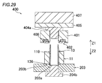
- the shaft pressing member 401 and the shaft 13 are integrally moved until the stepped portion 134 of the shaft 13 comes into contact with the stepped portion 203c of the fixing base 203.
- the spring member 408 is gradually contracted by being sandwiched between the core pressing member 402 that abuts on the end surface 11a of the rotor core 11 and the recess 401e of the shaft pressing member 401.
- the stepped portion 133 of the shaft 13 is pressed by the moving mechanism portion 407 via the shaft pressing member 401, and the end surface 11a of the rotor core 11 is pressed via the core pressing member 402 by the pressing force of the spring member 408. Will be done.
- pressing the end surface 11a of the rotor core 11 via the core pressing member 402 by the pressing force of the spring member 408 is sandwiched between the recess 401e of the shaft pressing member 401 and the core pressing member 402.
- the pressing force of the spring member 408 is to press the end surface 11a of the rotor core 11 via the core pressing member 402.
- the shaft is inserted by filling the inside of the shaft 13 with the fluid 40 and expanding the shaft 13 by pressurizing the fluid 40 while the shaft 13 and the rotor core 11 are pressed.
- the shaft 13 is fixed to the rotor core 11 by hydroforming in which the tubular portion 130 (see FIG. 2) is pressed against the inner peripheral surface 110a of the hole 110.
- the method for manufacturing the rotor (10) involves pressing the rotor core (11) in the direction of the central axis of the rotor core (11) by the core pressing members (202, 402). Be prepared. Further, in the method of manufacturing the rotor (10), the shaft (13) is filled with the fluid (40) and the fluid (40) is pressurized while the rotor core (11) is pressed. The shaft (13) is fixed to the rotor core (11) by hydroforming so that the shaft (13) is pressed against the inner peripheral surface (110a) of the shaft insertion hole (110) by expanding the shaft (13).
- hydroforming can be performed while the rotor core (11) is pressed by the core pressing members (202, 402). As a result, hydroforming can be performed in a state where the core pressing members (202, 402) prevent a gap from being generated between the electromagnetic steel plates (12) constituting the rotor core (11). As a result, hydroforming can be performed with the product thickness (t) of the rotor core (11) within a certain range (within the tolerance range). As a result, it is possible to prevent variations in the relative positional relationship (between products) between the shaft (13) and the rotor core (11).
- the step of inserting the shaft (13) is a step of inserting the first tubular portion (130) of the shaft (13) into the shaft insertion hole (110). is there.
- the step of pressing the rotor core (11) is provided on one side in the central axis direction from the first tubular portion (130), and has a diameter (r2) smaller than that of the first tubular portion (130).
- the step portion (133), which is the boundary portion between the second tubular portion (131) of (13) and the first tubular portion (130) of the shaft (13), is centered by the shaft pressing member (201, 401).
- the step portion (133) is pressed by the shaft pressing members (201, 401) to regulate the movement of the shaft (13) in the central axis direction, while the core pressing members (202, 402). It is possible to prevent a gap from being formed between the electromagnetic steel plates (12) constituting the rotor core (11).
- the step of pressing the end face (11a) of the rotor core (11) by the core pressing member (202, 402) is independent of the shaft pressing member (201, 401).
- the step portion (133) is pressed by the shaft pressing member (201, 401), and the end face (11a) of the rotor core (11) is pressed more reliably by the core pressing member (202, 402). be able to.
- the step portion (133) is pressed by the shaft pressing member (201, 401) in the central axis direction.
- the shaft (13) and the rotor core (11) are relatively positioned by pressing from one side and pressing the end face (11a) from one side in the central axis direction by the core pressing members (202, 402). It is a process. With this configuration, it is possible to more reliably prevent variations in the relative positional relationship between the shaft (13) and the rotor core (11).
- pressing the stepped portion (133) of the shaft (13) with the shaft pressing member (201, 401) means that the bearing portion (14) of the shaft (13) is pressed. ) Is pressed by the shaft pressing member (201, 401) as the step portion (133) as the bearing arrangement portion on which the) is arranged.
- the position of the step portion (133) as the bearing arrangement portion in the central axis direction can be fixed by pressing, so that the end surface (11a) of the rotor core (11) and the bearing arrangement portion are relative to each other. It is possible to prevent the positional relationship from fluctuating (between products).
- the shaft (13) first tubular portion (130)
- the bearing arrangement part may be deformed.
- the operation (rotation) of the shaft (13) (rotor core (11)) is relatively greatly affected. Therefore, it is possible to prevent the relative positional relationship between the end face (11a) of the rotor core (11) and the bearing arrangement portion from fluctuating.
- the step portion (133) is pressed by the shaft pressing members (201, 401).
- the shaft (13) is pressed against the shaft fixing portion (203a) arranged on the other side of the shaft (13) in the central axis direction, and the core pressing members (202, 402) press the shaft (13) on one side of the rotor core (11) in the center axis direction.
- the rotor core (11) By pressing the end face (11a) of the rotor core (11a), the rotor core (11) is pressed against the rotor core fixing portion (203b) arranged on the other side in the central axis direction of the core pressing member (202, 402), thereby pressing the shaft (13).
- This is a step of positioning the rotor core (11) relative to the rotor core (11).
- the rotor core (11) and the shaft (13) are fixed on the other side in the central axis direction, so that the end face (11a) of the rotor core (11) and the step portion (133) are relative to each other. It is possible to more easily prevent the positional relationship from fluctuating.
- the step of pressing the shaft (13) and the rotor core (11) is the shaft pressing included in the hydroforming dies (200a, 300a, 400a).
- the step portion (133) is pressed by the members (201, 401), and the end face (11a) of the rotor core (11) is pressed by the core pressing members (202, 402) included in the molds (200a, 300a, 400a). It is a process.
- the shaft pressing member (201, 401) and the core pressing member (202, 402) are included in the hydroforming mold (200a, 300a, 400a), whereby the shaft pressing member (201, 300a, 400a) is included.
- the pressing state of the stepped portion (133) by 401) and the pressing state of the end face (11a) by the core pressing members (202, 402) can be made relatively constant between products (between rotors (10)). .. As a result, it is possible to easily prevent variations in the relative positional relationship between the shaft (13) and the rotor core (11).
- the step of pressing the shaft (13) and the rotor core (11) is performed by the moving mechanism unit (207, 307, 407) of the shaft pressing member (201,
- the step portion (133) is pressed by the shaft pressing member (201, 401), and the moving mechanism portion (201, 401) is pressed.
- a stretchable telescopic member (208, 308, 408) provided between the core pressing member (202, 402) and the core pressing member (202, 402) of the rotor core (11) via the core pressing member (202, 402). This is a step of pressing the end face (11a).
- the relative positional relationship between the shaft pressing member (201, 401) and the core pressing member (202, 402) can be easily adjusted by expanding and contracting the telescopic member (208, 308, 408). can do.
- it becomes easy to both press the end face (11a) of the rotor core (11) by the core pressing member (202, 402) and press the step portion (133) by the shaft pressing member (201, 401). can do.
- the shaft pressing member (201, 401) and the shaft pressing member (202, 402) are moved.
- the shaft pressing member (201, 401) and the core pressing member (202, 402) can be brought closer to the rotor core (11) while maintaining a constant relative positional relationship with the core pressing member (202, 402).
- the core pressing member (202) is the rotor core by the moving mechanism unit (207, 307).
- the shaft pressing member (201) and the core pressing member (202) are integrally moved to the rotor core (11) side until they come into contact with the end surface (11a) of (11)
- the shaft pressing member (201) is moved to the rotor core (201). It is further moved to the 11) side, and the shaft pressing member (201) is brought into contact with the step portion (133) to be pressed, and the pressing force of the telescopic members (208, 308) causes the shaft pressing member (202) to pass through the core pressing member (202).
- the shaft pressing member (201) is brought into contact with the step portion (133) and then the core pressing member (202) is brought into contact with the end face (11a)
- the core pressing member (202) may not reach the end face (11a).
- the telescopic members (208, 308) ) Is moved while the shaft pressing member (201) is moved so that the shaft pressing member (201) is brought into contact with the step portion (133).
- pressing the end face (11a) of the rotor core (11) via the core pressing member (202) by the pressing force of the telescopic member (208) is a moving mechanism portion
- the end face (11a) of the rotor core (11) is pressed via the core pressing member (202) by driving the first cylinder member (208) as the telescopic member (208) by the hydraulic pressure from the outside of the 207).
- the force for pressing the end face (11a) of the rotor core (11) can be easily adjusted by adjusting the hydraulic pressure for driving the first cylinder member (208).
- pressing the end face (11a) of the rotor core (11) via the core pressing member (202) by the pressing force of the elastic member (308) is a moving mechanism unit (12a).
- the end face (11a) of the rotor core (11) is sandwiched between the core pressing member (202) and the end face (11a) of the rotor core (11) via the core pressing member (202) due to the pressing force of the second cylinder member (308) which is elastically expanded and contracted. Is to press.
- the end face (11a) of the rotor core (11) can be pressed by the elastic force of the second cylinder member (308) in the contracted state.
- pressing the end face (11a) of the rotor core (11) via the core pressing member (402) by the pressing force of the telescopic member (408) is a shaft pressing member (48).
- the end face (11a) of the rotor core (11) is pressed via the core pressing member (402) by the pressing force of the urging member (408) sandwiched between the recess (401e) of the 401) and the core pressing member (402). It is to press.
- the end face (11a) of the rotor core (11) can be pressed by the urging force (elastic force) of the urging member (408) in the contracted state.
- the rotor (10) manufacturing apparatus (200, 300, 400) is a core pressing member (200, 300, 400) that presses the rotor core (11) in the direction of the central axis of the rotor core (11).
- a mold pressing portion (200b, 400b) including 202, 402) is provided.
- the rotor (10) manufacturing apparatus (200, 300, 400) fills the inside of the shaft (13) with the fluid (40) and adds the fluid (40) while the rotor core (11) is pressed.
- hydroforming can be performed while the rotor core (11) is pressed by the core pressing members (202, 402).
- hydroforming can be performed in a state where the core pressing members (202, 402) prevent a gap from being generated between the electromagnetic steel plates (12) constituting the rotor core (11).
- hydroforming can be performed with the product thickness (t) of the rotor core (11) within a certain range (within the tolerance range).
- the rotor (10) manufacturing apparatus (200, 300, 400) capable of preventing variations in the relative positional relationship (between products) between the shaft (13) and the rotor core (11). Can be provided.
- the mold pressing portions (200b, 400b) are the first tubular portion (130) of the shaft (13) and the first tubular portion (130).
- a step portion (133) which is provided on one side in the direction of the central axis and is a boundary portion with the second tubular portion (131) having a diameter (r2) smaller than that of the first tubular portion (130).
- the core pressing members (202, 402) are configured to press the end surface (11a) on one side in the central axis direction of the rotor core (11) from one side in the central axis direction.
- the hydroforming portion (204, 304, 404) has a first tubular portion on the inner peripheral surface (110a) of the shaft insertion hole (110) in a state where the rotor core (11) and the shaft (13) are pressed. It is provided for hydroforming in which (130) is pressure-welded. With this configuration, the step portion (133) is pressed by the shaft pressing members (201, 401) to regulate the movement of the shaft (13) in the central axis direction, while the core pressing members (202, 402). It is possible to provide a rotor (10) manufacturing apparatus (200, 300, 400) capable of preventing a gap from being formed between the electromagnetic steel plates (12) constituting the rotor core (11).
- the core pressing member (202, 402) is configured to be operable independently of the shaft pressing member (201, 401). With this configuration, while pressing the stepped portion (133) with the shaft pressing member (201, 401), the core pressing member (202, 402) more reliably presses the end surface (11a) of the rotor core (11). It is possible to provide a rotor (10) manufacturing apparatus (200, 300, 400) capable of this.
- the shaft pressing member (201, 401) includes the shaft pressing member main body portion (201a, 401a) having an annular shape and the shaft pressing member main body portion (201a). , 401a), and includes a tubular pressing portion (201c, 401c) provided on the inner peripheral side and extending from the shaft pressing member main body portions (201a, 401a) toward the other side in the central axis direction. Further, in the tubular pressing portion (201c, 401c), the other end portion (201d, 401d) of the tubular pressing portion (201c, 401c) in the central axis direction is in contact with the step portion (133).
- the tubular pressing portion (201c, 401c) presses the stepped portion (133) of the shaft (13) to fix the position of the shaft (13) in the central axis direction while performing the tubular pressing.
- the rotor (10) manufacturing apparatus (200, 300, 400) is arranged on the other side of the shaft (13) in the central axis direction, and is centered on the shaft.
- a rotor core (203a) that is fixed from the other side in the axial direction and a rotor core that is arranged on the other side in the central axis direction of the core pressing members (202, 402) and fixes the rotor core (11) from the other side in the central axis direction.
- a fixing base (203) including a fixing portion (203b) is provided.
- the rotor core (11) and the shaft (13) are fixed on the other side in the central axis direction, so that the end face (11a) of the rotor core (11) and the step portion (133) are relative to each other. It is possible to provide a rotor (10) manufacturing apparatus (200, 300, 400) capable of more easily preventing the positional relationship from fluctuating.
- the rotor (10) manufacturing apparatus (200, 300, 400) includes the shaft pressing member (201, 401) and the core pressing member (202, 402). Is provided between the moving mechanism unit (207, 307, 407), the moving mechanism unit (207, 307, 407), and the core pressing member (202, 402) for integrally moving the rotor core (11) side. It includes telescopic members (208, 308, 408) that are configured to be stretchable along the central axis direction. Further, the moving mechanism portion (207, 307, 407) is configured to press the step portion (133) via the shaft pressing member (201, 401), and the telescopic member (208, 308, 408) is the core.
- the shaft pressing member (401) includes a recess (401e) provided on the other side in the central axis direction. Further, the core pressing member (402) is provided so as to engage with the recess (401e). Further, the telescopic member (408) includes an urging member (408) sandwiched between the recess (401e) of the shaft pressing member (401) and the core pressing member (402). With this configuration, the end face (11a) of the rotor core (11) is pressed by the urging force (elastic force) of the urging member (408) in a state of being contracted by the recess (401e) and the core pressing member (402). It is possible to provide a rotor (10) manufacturing apparatus (400) capable of the above.
- the telescopic member (208) includes the first cylinder member (208) driven by the flood control from the outside of the moving mechanism portion (207).
- the rotor (10) can easily adjust the force pressing the end face (11a) of the rotor core (11) by adjusting the hydraulic pressure that drives the first cylinder member (208).
- Manufacturing equipment (200) can be provided.
- the telescopic member (308) is sandwiched between the moving mechanism portion (307) and the core pressing member (202), and the elastically stretchable second cylinder member (20). 308) is included.
- the rotor (10) manufacturing apparatus (300) capable of pressing the end face (11a) of the rotor core (11) by the elastic force of the second cylinder member (308) in the contracted state is provided. Can be provided.
- the core pressing member (202) has a core pressing member main body (202a) that abuts on the end surface (11a) of the rotor core (11) and a core pressing member main body.
- a core pressing member side shaft (202f) extending from the portion (202a) to one side in the central axis direction is included.
- the shaft pressing member (201a) includes a through hole (201e) through which the core pressing member side shaft (202f) penetrates, and the core pressing member side shaft (202f) is penetrated through the through hole (201e).
- the core pressing member side shaft (202f) can be moved independently between the telescopic members (208, 308) and the core pressing member main body (202a).
- the telescopic members (208, 308) are the end portion (202 g) and the central axis of the core pressing member side shaft (202f) protruding from the through hole (201e) of the shaft pressing member (201a) to one side in the central axis direction. It is provided so as to be adjacent along the direction. With this configuration, even when the shaft pressing member (201a) is provided between the telescopic member (208, 308) and the core pressing member main body (202a), the through hole of the shaft pressing member (201a) is provided.
- the core pressing member main body (202a) (end surface (11a) of the rotor core (11)) can be pressed by the telescopic members (208, 308) via the core pressing member side shaft (202f) penetrating (201e). ..
- the shaft pressing member (201a) is configured to be movable independently of the core pressing member side shaft (202f) in a state where the core pressing member side shaft (202f) is penetrated through the through hole (201e).
- the step portion (133) of the rotor core (11) can be easily pressed by the shaft pressing member (201a) independently of the pressing of the core pressing member side shaft (202f) by the telescopic members (208, 308). Can be done.
- the moving mechanism unit (207, 307, 407) integrally moves the shaft pressing member (201, 401) and the core pressing member (202, 402).
- the present invention is not limited to this.
- the shaft pressing member (201, 401) and the core pressing member (202, 402) may be moved independently by a separate moving mechanism unit.
- the rotor core fixing portion 203b and the shaft fixing portion 203a are integrally formed, but the present invention is not limited to this.
- the rotor core fixing portion and the shaft fixing portion may be provided separately.
- the step portion 133 of the shaft 13 is an example in which the bearing portion 14 is arranged, but the present invention is not limited to this.
- the stepped portion 133 of the shaft 13 may be a portion other than the bearing arrangement portion.
- the core pressing member (202, 402) is used to press the entire surface of the end surface 11a of the rotor core 11, but the present invention is not limited to this. Only a part of the end face 11a of the rotor core 11 may be pressed by the core pressing member (202, 402).
- the shaft pressing member (201, 401) has shown an example in which the entire circumference of the stepped portion 133 of the shaft 13 is pressed, but the present invention is not limited to this.
- the shaft pressing member (201, 401) may press only a part of the entire circumference of the stepped portion 133 of the shaft 13.
- the core pressing member 202 is brought into contact with the end surface 11a of the rotor core 11 and then the shaft pressing member 201 is brought into contact with the stepped portion 133 of the shaft 13.
- the present invention is not limited to this.
- the shaft pressing member 201 may be brought into contact with the stepped portion 133 of the shaft 13, and then the core pressing member 202 may be brought into contact with the end surface 11a of the rotor core 11.
- the shaft pressing member 201 may be brought into contact with the stepped portion 133 of the shaft 13 and the core pressing member 202 may be brought into contact with the end surface 11a of the rotor core 11 at the same time.
- the end surface 11a of the rotor core 11 is pressed by the hydraulic cylinder 208 (expansion / contraction member, first cylinder member) is shown, but the present invention is not limited to this.
- the end face 11a of the rotor core 11 may be pressed by a cylinder other than the hydraulic cylinder 208 (expandable member, first cylinder member) (for example, an air cylinder or a spring member).
- the end face 11a of the rotor core 11 may be pressed by a cylinder other than the air cylinder 308 (expandable member, second cylinder member) (for example, a hydraulic cylinder or a spring member).
- the shaft pressing member 401 is brought into contact with the stepped portion 133 of the shaft 13 and then the core pressing member 402 is brought into contact with the end surface 11a of the rotor core 11.
- the core pressing member 402 may be brought into contact with the end surface 11a of the rotor core 11, and then the shaft pressing member 401 may be brought into contact with the step portion 133 of the shaft 13.
- the shaft pressing member 401 may be brought into contact with the stepped portion 133 of the shaft 13 and the core pressing member 402 may be brought into contact with the end surface 11a of the rotor core 11 at the same time.
- the present invention is not limited to this.
- An example of pressing the end face 11a of the rotor core 11 has been shown, but the present invention is not limited to this.
- the end face 11a of the rotor core 11 may be pressed by a cushion material other than the spring member 408.
- the shaft 13 is moved and pressed against the shaft fixing portion 203a by pressing the stepped portion 133 of the shaft 13 with the shaft pressing members (201, 401).
- the present invention is not limited to this.
- the shaft pressing member (201, 401) may be brought into contact with the shaft 13 fixed in the shaft fixing portion 203a.
- the rotor core 11 is pressed by the core pressing member (202, 402) while pressing the stepped portion 133 of the shaft 13 by the shaft pressing member (201, 401).
- the present invention is not limited to this.
- the rotor core 11 may be pressed by the core pressing members (202, 402) without pressing the stepped portion 133 of the shaft 13.
Landscapes
- Engineering & Computer Science (AREA)
- Power Engineering (AREA)
- Manufacturing & Machinery (AREA)
- Mechanical Engineering (AREA)
- Manufacture Of Motors, Generators (AREA)
- Iron Core Of Rotating Electric Machines (AREA)
- Shaping Metal By Deep-Drawing, Or The Like (AREA)
Abstract
Description
(ロータの構造)
図1~図14を参照して、第1実施形態によるロータ10の構造について説明する。
図3に示すように、ロータ10の製造装置200は、ハイドロフォーミング用の金型200aを含む。ハイドロフォーミング用の金型200aは、金型押圧部200bを有する。ロータ10の製造装置200(200a、200b)は、シャフト押圧部材201と、コア押圧部材202と、を備える。
次に、図1、図3~図5、および、図8~図14を参照して、ロータ10の製造方法について説明する。
次に、図2、および、図15~図23を参照して、第2実施形態によるロータ10の製造方法、および、ロータ10の製造装置300について説明する。第2実施形態のロータ10の製造方法、および、ロータ10の製造装置300では、油圧により駆動される油圧シリンダ208が用いられている上記第1実施形態とは異なり、弾性的に変化するエアシリンダ308が用いられる。なお、上記第1実施形態と同様の構成は、第1実施形態と同じ符号を付して図示するとともに説明を省略する。
図15に示すように、ロータ10の製造装置300は、ハイドロフォーミング用の金型300aを含む。ハイドロフォーミング用の金型300aは、金型押圧部200bを有する。ロータ10の製造装置300(300a、200b)は、シャフト押圧部材201と、コア押圧部材202と、を備える。
次に、図18~図23を参照して、ロータ10の製造方法について説明する。
次に、図2、および、図24~図33を参照して、第3実施形態によるロータ10の製造方法、および、ロータ10の製造装置400について説明する。第3実施形態のロータ10の製造方法、および、ロータ10の製造装置400では、シリンダ(油圧シリンダ208)が用いられている上記第1実施形態とは異なり、ばね部材408が用いられる。なお、上記第1実施形態と同様の構成は、第1実施形態と同じ符号を付して図示するとともに説明を省略する。
図24に示すように、ロータ10の製造装置400は、ハイドロフォーミング用の金型400aを含む。ハイドロフォーミング用の金型400aは、金型押圧部400bを有する。ロータ10の製造装置400(400a、400b)は、シャフト押圧部材401と、コア押圧部材402と、を備える。
次に、図29~図33を参照して、ロータ10の製造方法について説明する。
上記第1~第3実施形態では、以下のような効果を得ることができる。
第1~第3実施形態では、上記のように、ロータ(10)の製造方法は、コア押圧部材(202、402)によりロータコア(11)をロータコア(11)の中心軸線方向に押圧する工程を備える。また、ロータ(10)の製造方法は、ロータコア(11)が押圧された状態で、シャフト(13)の内部に流体(40)を充填させるとともに流体(40)を加圧することによってシャフト(13)を膨張させることにより、シャフト挿入孔(110)の内周面(110a)にシャフト(13)を圧接させるハイドロフォーミングによって、シャフト(13)をロータコア(11)に固定する工程と、を備える。これにより、コア押圧部材(202、402)によりロータコア(11)を押圧した状態でハイドロフォーミングを行うことができる。その結果、コア押圧部材(202、402)によりロータコア(11)を構成する電磁鋼板(12)同士の間に隙間が生じるのを防止した状態で、ハイドロフォーミングを行うことができる。これにより、ロータコア(11)の積厚(t)を一定の範囲内(公差範囲内)に収めた状態でハイドロフォーミングを行うことができる。その結果、シャフト(13)とロータコア(11)との相対的な位置関係に(製品間で)ばらつきが生じるのを防止することができる。
第1~第3実施形態では、上記のように、ロータ(10)の製造装置(200、300、400)は、ロータコア(11)をロータコア(11)の中心軸線方向に押圧するコア押圧部材(202、402)を含む金型押圧部(200b、400b)を備える。また、ロータ(10)の製造装置(200、300、400)は、ロータコア(11)が押圧された状態で、シャフト(13)の内部に流体(40)を充填させるとともに流体(40)を加圧することによってシャフト(13)を膨張させることにより、シャフト挿入孔(110)の内周面(110a)にシャフト(13)を圧接させるハイドロフォーミングを行うためのハイドロフォーミング部(204、304、404)を備える。これにより、コア押圧部材(202、402)によりロータコア(11)を押圧した状態でハイドロフォーミングを行うことができる。その結果、コア押圧部材(202、402)によりロータコア(11)を構成する電磁鋼板(12)同士の間に隙間が生じるのを防止した状態で、ハイドロフォーミングを行うことができる。これにより、ロータコア(11)の積厚(t)を一定の範囲内(公差範囲内)に収めた状態でハイドロフォーミングを行うことができる。その結果、シャフト(13)とロータコア(11)との相対的な位置関係に(製品間で)ばらつきが生じるのを防止することが可能なロータ(10)の製造装置(200、300、400)を提供することができる。
なお、今回開示された実施形態は、すべての点で例示であって制限的なものではないと考えられるべきである。本発明の範囲は、上記した実施形態の説明ではなく請求の範囲によって示され、さらに請求の範囲と均等の意味および範囲内でのすべての変更(変形例)が含まれる。
11 ロータコア
11a 端面(ロータコアの中心軸線方向の一方側の端面)
13 シャフト
14 軸受け部
40 流体
110 シャフト挿入孔
110a 内周面
130 筒状部分(第1筒状部分)
131 筒状部分(第2筒状部分)
133 段差部
200、300、400 製造装置
200a、300a、400a 金型
200b、400b 金型押圧部
201、401 シャフト押圧部材
201a、401a シャフト押圧部材本体部
201c、401c 筒状押圧部
201d、401d 端部(筒状押圧部の端部)
201e 貫通孔(コア押圧部材側シャフトが貫通する貫通孔)
202、402 コア押圧部材
202a コア押圧部材本体部
202f コア押圧部材側シャフト
202g 端部(コア押圧部材側シャフトの端部)
203 固定台
203a シャフト固定部
203b ロータコア固定部
204、304、404 ハイドロフォーミング部
207、307、407 移動機構部
208 油圧シリンダ(伸縮部材、第1シリンダ部材)
308 エアシリンダ(伸縮部材、第2シリンダ部材)
401e 凹部
408 ばね部材(伸縮部材、付勢部材)
r2 直径(第2筒状部分の直径)
Claims (20)
- シャフト挿入孔を有する環状のロータコアと、筒状のシャフトと、を含むロータの製造方法であって、
前記ロータコアの前記シャフト挿入孔に、前記シャフトを挿入する工程と、
コア押圧部材により前記ロータコアを前記ロータコアの中心軸線方向に押圧する工程と、
前記ロータコアが押圧された状態で、前記シャフトの内部に流体を充填させるとともに前記流体を加圧することによって前記シャフトを膨張させることにより、前記シャフト挿入孔の内周面に前記シャフトを圧接させるハイドロフォーミングによって、前記シャフトを前記ロータコアに固定する工程と、を備える、ロータの製造方法。 - 前記シャフトを挿入する工程は、前記シャフト挿入孔に、前記シャフトの第1筒状部分を挿入する工程であり、
前記ロータコアを押圧する工程は、前記第1筒状部分よりも前記中心軸線方向の一方側に設けられ、前記第1筒状部分よりも小さい直径を有する前記シャフトの第2筒状部分と、前記シャフトの前記第1筒状部分との境界部分である段差部を、シャフト押圧部材により前記中心軸線方向の一方側から押圧するとともに、前記コア押圧部材により前記ロータコアの前記中心軸線方向の一方側の端面を前記中心軸線方向の一方側から押圧する工程であり、
前記シャフトを前記ロータコアに固定する工程は、前記ロータコアと前記シャフトとが押圧された状態で、前記シャフト挿入孔の前記内周面に前記第1筒状部分を圧接させるハイドロフォーミングによって、前記シャフトを前記ロータコアに固定する工程である、請求項1に記載のロータの製造方法。 - 前記コア押圧部材により前記ロータコアの前記端面を押圧する工程は、前記シャフト押圧部材とは独立して動作可能な前記コア押圧部材により前記ロータコアの前記端面を押圧する工程である、請求項2に記載のロータの製造方法。
- 前記シャフトと前記ロータコアとを押圧する工程は、前記段差部を前記シャフト押圧部材により前記中心軸線方向の一方側から押圧するとともに、前記コア押圧部材により前記端面を前記中心軸線方向の一方側から押圧することにより、前記シャフトと前記ロータコアとを相対的に位置決めする工程である、請求項2または3に記載のロータの製造方法。
- 前記シャフトの前記段差部を前記シャフト押圧部材により押圧することは、前記シャフトの軸受け部が配置される軸受け配置部としての前記段差部を前記シャフト押圧部材により押圧することである、請求項2~4のいずれか1項に記載のロータの製造方法。
- 前記シャフトと前記ロータコアとを押圧する工程は、前記段差部を前記シャフト押圧部材により押圧して前記シャフトを前記シャフトの前記中心軸線方向の他方側に配置されるシャフト固定部に押し付けるとともに、前記コア押圧部材により前記ロータコアの前記中心軸線方向の一方側の前記端面を押圧することにより、前記ロータコアを前記コア押圧部材の前記中心軸線方向の他方側に配置されるロータコア固定部に押し付けることにより、前記シャフトに対して前記ロータコアを相対的に位置決めする工程である、請求項2~5のいずれか1項に記載のロータの製造方法。
- 前記シャフトと前記ロータコアとを押圧する工程は、ハイドロフォーミング用の金型に含まれる前記シャフト押圧部材により前記段差部を押圧するとともに、前記金型に含まれる前記コア押圧部材により前記ロータコアの前記端面を押圧する工程である、請求項2~6のいずれか1項に記載のロータの製造方法。
- 前記シャフトと前記ロータコアとを押圧する工程は、移動機構部により、前記シャフト押圧部材と前記コア押圧部材とを前記ロータコア側に一体的に移動させることにより、前記段差部を前記シャフト押圧部材により押圧するとともに、前記移動機構部と前記コア押圧部材との間に設けられる伸縮可能な伸縮部材により前記コア押圧部材を介して前記ロータコアの前記端面を押圧する工程である、請求項2~7のいずれか1項に記載のロータの製造方法。
- 前記シャフトと前記ロータコアとを押圧する工程は、前記移動機構部により、前記コア押圧部材が前記ロータコアの前記端面に当接するまで前記シャフト押圧部材と前記コア押圧部材とを一体的に前記ロータコア側に移動させた後、前記シャフト押圧部材を前記ロータコア側にさらに移動させて、前記シャフト押圧部材を前記段差部に当接させて押圧するとともに、前記伸縮部材の押圧力により、前記コア押圧部材を介して前記ロータコアの前記端面を押圧する工程である、請求項8に記載のロータの製造方法。
- 前記伸縮部材の押圧力により前記コア押圧部材を介して前記ロータコアの前記端面を押圧することは、前記移動機構部の外部からの油圧により、前記伸縮部材としての第1シリンダ部材を駆動させることにより前記コア押圧部材を介して前記ロータコアの前記端面を押圧することである、請求項8または9に記載のロータの製造方法。
- 前記伸縮部材の押圧力により前記コア押圧部材を介して前記ロータコアの前記端面を押圧することは、前記移動機構部と前記コア押圧部材との間に挟持され、弾性的に伸縮する第2シリンダ部材の押圧力により前記コア押圧部材を介して前記ロータコアの前記端面を押圧することである、請求項8または9に記載のロータの製造方法。
- 前記伸縮部材の押圧力により前記コア押圧部材を介して前記ロータコアの前記端面を押圧することは、前記シャフト押圧部材の凹部と前記コア押圧部材との間に挟持された付勢部材の押圧力により前記コア押圧部材を介して前記ロータコアの前記端面を押圧することである、請求項8または9に記載のロータの製造方法。
- シャフト挿入孔を有する環状のロータコアと、筒状のシャフトと、を含むロータの製造装置であって、
前記ロータコアを前記ロータコアの中心軸線方向に押圧するコア押圧部材を含む金型押圧部と、
前記ロータコアが押圧された状態で、前記シャフトの内部に流体を充填させるとともに前記流体を加圧することによって前記シャフトを膨張させることにより、前記シャフト挿入孔の内周面に前記シャフトを圧接させるハイドロフォーミングを行うためのハイドロフォーミング部と、を備える、ロータの製造装置。 - 前記金型押圧部は、前記シャフトの第1筒状部分と、前記第1筒状部分よりも前記中心軸線方向の一方側に設けられ、前記第1筒状部分よりも小さい直径を有する第2筒状部分との境界部分である段差部を、前記中心軸線方向の一方側から押圧するシャフト押圧部材をさらに含み、
前記コア押圧部材は、前記ロータコアの前記中心軸線方向の一方側の端面を前記中心軸線方向の一方側から押圧するように構成されており、
前記ハイドロフォーミング部は、前記ロータコアと前記シャフトとが押圧された状態で、前記シャフト挿入孔の前記内周面に前記第1筒状部分を圧接させるハイドロフォーミングを行うために設けられている、請求項13に記載のロータの製造装置。 - 前記コア押圧部材は、前記シャフト押圧部材とは独立して動作可能に構成されている、請求項14に記載のロータの製造装置。
- 前記シャフト押圧部材は、円環形状を有するシャフト押圧部材本体部と、前記シャフト押圧部材本体部の内周側に設けられ、前記シャフト押圧部材本体部から前記中心軸線方向の他方側に向かって延びるように設けられる筒状押圧部とを含み、
前記筒状押圧部は、前記筒状押圧部の前記中心軸線方向の他方側の端部が前記段差部と当接した状態で、前記シャフトの前記第2筒状部分を外周側からガイドするように設けられている、請求項14または15に記載のロータの製造装置。 - 前記シャフトの前記中心軸線方向の他方側に配置され、前記シャフトを前記中心軸線方向の他方側から固定するシャフト固定部と、前記コア押圧部材の前記中心軸線方向の他方側に配置され、前記ロータコアを前記中心軸線方向の他方側から固定するロータコア固定部とを含む固定台をさらに備える、請求項14~16のいずれか1項に記載のロータの製造装置。
- 前記シャフト押圧部材と前記コア押圧部材とを前記ロータコア側に一体的に移動させる移動機構部と、
前記移動機構部と前記コア押圧部材との間に設けられ、前記中心軸線方向に沿って伸縮可能に構成されている伸縮部材と、をさらに備え、
前記移動機構部は、前記シャフト押圧部材を介して前記段差部を押圧するように構成され、
前記伸縮部材は、前記コア押圧部材を介して前記ロータコアの前記端面を押圧するように構成されている、請求項14~17のいずれか1項に記載のロータの製造装置。 - 前記シャフト押圧部材は、前記中心軸線方向の他方側に設けられる凹部を含み、
前記コア押圧部材は、前記凹部に係合するように設けられており、
前記伸縮部材は、前記シャフト押圧部材の前記凹部と前記コア押圧部材との間に挟持された付勢部材を含む、請求項18に記載のロータの製造装置。 - 前記伸縮部材は、前記移動機構部の外部からの油圧により駆動される第1シリンダ部材を含む、請求項18に記載のロータの製造装置。
Priority Applications (3)
| Application Number | Priority Date | Filing Date | Title |
|---|---|---|---|
| US17/602,295 US11962204B2 (en) | 2019-06-20 | 2020-05-21 | Rotor manufacturing method and rotor manufacturing apparatus |
| CN202080043302.0A CN113994576A (zh) | 2019-06-20 | 2020-05-21 | 转子的制造方法以及转子的制造装置 |
| EP20825668.5A EP3989419B1 (en) | 2019-06-20 | 2020-05-21 | Rotor manufacturing method and rotor manufacturing device |
Applications Claiming Priority (2)
| Application Number | Priority Date | Filing Date | Title |
|---|---|---|---|
| JP2019114521A JP7302324B2 (ja) | 2019-06-20 | 2019-06-20 | ロータの製造方法およびロータの製造装置 |
| JP2019-114521 | 2019-06-20 |
Publications (1)
| Publication Number | Publication Date |
|---|---|
| WO2020255618A1 true WO2020255618A1 (ja) | 2020-12-24 |
Family
ID=73994305
Family Applications (1)
| Application Number | Title | Priority Date | Filing Date |
|---|---|---|---|
| PCT/JP2020/020180 Ceased WO2020255618A1 (ja) | 2019-06-20 | 2020-05-21 | ロータの製造方法およびロータの製造装置 |
Country Status (5)
| Country | Link |
|---|---|
| US (1) | US11962204B2 (ja) |
| EP (1) | EP3989419B1 (ja) |
| JP (1) | JP7302324B2 (ja) |
| CN (1) | CN113994576A (ja) |
| WO (1) | WO2020255618A1 (ja) |
Cited By (1)
| Publication number | Priority date | Publication date | Assignee | Title |
|---|---|---|---|---|
| CN116111788A (zh) * | 2023-04-12 | 2023-05-12 | 中山市德信自动化设备科技有限公司 | 一种电机轴压入机 |
Families Citing this family (3)
| Publication number | Priority date | Publication date | Assignee | Title |
|---|---|---|---|---|
| JP7302324B2 (ja) * | 2019-06-20 | 2023-07-04 | 株式会社アイシン | ロータの製造方法およびロータの製造装置 |
| JP7438170B2 (ja) | 2021-09-09 | 2024-02-26 | 東芝三菱電機産業システム株式会社 | 回転電機の製造方法 |
| WO2023162070A1 (ja) * | 2022-02-24 | 2023-08-31 | 株式会社アイシン | 回転電機用のロータの製造方法 |
Citations (5)
| Publication number | Priority date | Publication date | Assignee | Title |
|---|---|---|---|---|
| JPS53149608A (en) * | 1978-05-18 | 1978-12-27 | Mitsubishi Electric Corp | Manufacture method of laminated iron core |
| JP2001268858A (ja) | 2000-03-17 | 2001-09-28 | Toyota Autom Loom Works Ltd | モータ用ロータ、電動圧縮機及びモータ用ロータの製造方法 |
| US20140097711A1 (en) * | 2012-10-05 | 2014-04-10 | Larry Kubes | One piece rotor hub/shaft for an electric machine and method |
| JP2014529508A (ja) * | 2011-09-01 | 2014-11-13 | ローベルト ボッシュ ゲゼルシャフト ミット ベシュレンクテル ハフツング | 複合部品としてのねじ付き部品を製造する方法、転動体ねじ装置、リニアアクチュエータ、このような複合部品を備える電気機械式のブレーキ倍力装置 |
| JP2017041991A (ja) * | 2015-08-20 | 2017-02-23 | トヨタ自動車株式会社 | ロータコアの製造方法 |
Family Cites Families (7)
| Publication number | Priority date | Publication date | Assignee | Title |
|---|---|---|---|---|
| GB9727063D0 (en) * | 1997-12-23 | 1998-02-18 | Gkn Sankey Ltd | A hydroforming process |
| DE102008043661A1 (de) * | 2008-11-12 | 2010-05-20 | Robert Bosch Gmbh | Welle für eine elektrische Maschine, insbesondere für einen Motorgenerator |
| EP2887502B1 (en) * | 2013-12-18 | 2016-10-05 | Skf Magnetic Mechatronics | Rotor assembly with permanent magnets and method of manufacture |
| JP6484002B2 (ja) * | 2014-10-29 | 2019-03-13 | Kyb株式会社 | ロータ及びロータ製造方法 |
| DE102016215090A1 (de) * | 2016-08-12 | 2018-02-15 | Thyssenkrupp Ag | Verfahren zur Montage einer Rotorwelle eines Elektromotors |
| DE112016007296T5 (de) * | 2016-09-30 | 2019-06-13 | Nidec Corporation | Verfahren zum herstellen eines rotors, rotor und motor |
| JP7302324B2 (ja) * | 2019-06-20 | 2023-07-04 | 株式会社アイシン | ロータの製造方法およびロータの製造装置 |
-
2019
- 2019-06-20 JP JP2019114521A patent/JP7302324B2/ja active Active
-
2020
- 2020-05-21 CN CN202080043302.0A patent/CN113994576A/zh active Pending
- 2020-05-21 EP EP20825668.5A patent/EP3989419B1/en active Active
- 2020-05-21 WO PCT/JP2020/020180 patent/WO2020255618A1/ja not_active Ceased
- 2020-05-21 US US17/602,295 patent/US11962204B2/en active Active
Patent Citations (5)
| Publication number | Priority date | Publication date | Assignee | Title |
|---|---|---|---|---|
| JPS53149608A (en) * | 1978-05-18 | 1978-12-27 | Mitsubishi Electric Corp | Manufacture method of laminated iron core |
| JP2001268858A (ja) | 2000-03-17 | 2001-09-28 | Toyota Autom Loom Works Ltd | モータ用ロータ、電動圧縮機及びモータ用ロータの製造方法 |
| JP2014529508A (ja) * | 2011-09-01 | 2014-11-13 | ローベルト ボッシュ ゲゼルシャフト ミット ベシュレンクテル ハフツング | 複合部品としてのねじ付き部品を製造する方法、転動体ねじ装置、リニアアクチュエータ、このような複合部品を備える電気機械式のブレーキ倍力装置 |
| US20140097711A1 (en) * | 2012-10-05 | 2014-04-10 | Larry Kubes | One piece rotor hub/shaft for an electric machine and method |
| JP2017041991A (ja) * | 2015-08-20 | 2017-02-23 | トヨタ自動車株式会社 | ロータコアの製造方法 |
Non-Patent Citations (1)
| Title |
|---|
| See also references of EP3989419A4 |
Cited By (2)
| Publication number | Priority date | Publication date | Assignee | Title |
|---|---|---|---|---|
| CN116111788A (zh) * | 2023-04-12 | 2023-05-12 | 中山市德信自动化设备科技有限公司 | 一种电机轴压入机 |
| CN116111788B (zh) * | 2023-04-12 | 2023-08-08 | 中山市德信自动化设备科技有限公司 | 一种电机轴压入机 |
Also Published As
| Publication number | Publication date |
|---|---|
| EP3989419A4 (en) | 2022-08-17 |
| JP2021002908A (ja) | 2021-01-07 |
| US11962204B2 (en) | 2024-04-16 |
| CN113994576A (zh) | 2022-01-28 |
| EP3989419A1 (en) | 2022-04-27 |
| EP3989419B1 (en) | 2026-03-25 |
| JP7302324B2 (ja) | 2023-07-04 |
| US20220166294A1 (en) | 2022-05-26 |
Similar Documents
| Publication | Publication Date | Title |
|---|---|---|
| WO2020255618A1 (ja) | ロータの製造方法およびロータの製造装置 | |
| US9780630B2 (en) | Method for manufacturing motor rotor including a resolver rotor for detecting rotation position | |
| US9016345B2 (en) | Rotary lamination apparatus | |
| JP2007318942A (ja) | 磁石埋込型回転子の射出成形用金型装置および製造方法 | |
| CN104025432B (zh) | 定子铁芯的制造方法和定子铁芯 | |
| JP2009017712A (ja) | 永久磁石モータ及びその製造方法 | |
| JP5496760B2 (ja) | 分割コアの巻線方法および巻線装置 | |
| US11370152B2 (en) | Rotor manufacturing method and rotor manufacturing apparatus | |
| WO2023120169A1 (ja) | 回転電機用のロータの製造方法及び製造装置 | |
| JP7167805B2 (ja) | ロータの製造方法 | |
| JP2007159342A (ja) | 電動機のロータの作製に使用される型 | |
| JP2016171740A (ja) | ステータ、回転電機、ステータの製造方法、および巻線装置 | |
| JP4785886B2 (ja) | 回転電機用ロータの製造装置 | |
| JP2021083189A (ja) | ロータの製造方法 | |
| CN117378128A (zh) | 包括能移动的控制件的用于凸极转子的覆盖滑动件、凸极转子和电机 | |
| JP2008278684A (ja) | 一体成形方法 | |
| JP2024111897A (ja) | 回転電機用のロータの製造装置、製造方法、及び回転電機用のロータ | |
| CN101073192B (zh) | 制造电机用电磁元件的制造装置 | |
| JP2021118664A (ja) | 固定子およびその製造方法 | |
| JP7221365B1 (ja) | 回転電機、エレベータのドア装置、及び回転電機の製造方法 | |
| CN104704712B (zh) | 旋转电机及其制造方法 | |
| JP2025119156A (ja) | 回転電機用のロータの製造方法 | |
| JP5146077B2 (ja) | モータ及びその製造方法 | |
| JP4517652B2 (ja) | 回転電機の組立装置及びこれを利用する組立方法 | |
| JP2022055143A (ja) | 管材の加工方法 |
Legal Events
| Date | Code | Title | Description |
|---|---|---|---|
| 121 | Ep: the epo has been informed by wipo that ep was designated in this application |
Ref document number: 20825668 Country of ref document: EP Kind code of ref document: A1 |
|
| NENP | Non-entry into the national phase |
Ref country code: DE |
|
| WWE | Wipo information: entry into national phase |
Ref document number: 2020825668 Country of ref document: EP |
|
| ENP | Entry into the national phase |
Ref document number: 2020825668 Country of ref document: EP Effective date: 20220120 |
|
| WWG | Wipo information: grant in national office |
Ref document number: 2020825668 Country of ref document: EP |